Gaze, Posture and Gesture Recognition to Minimize Focus...
20
Gaze, Posture and Gesture Recognition to Minimize Focus Shifts for Intelligent Operating Rooms in a Collaborative Support System J. P. Wachs Abstract This paper describes the design of intelligent, collaborative operating rooms based on highly intuitive, natural and multimodal interaction. Intelligent operating rooms minimize surgeon’s focus shifts by minimizing both the focus spatial offset (distance moved by surgeon’s head or gaze to the new target) and the movement spatial offset (distance surgeon covers physically). These spatio-temporal measures have an impact on the surgeon’s performance in the operating room. I describe how machine vision techniques are used to extract spatio-temporal measures and to interact with the system, and how computer graphics techniques can be used to display visual medical information effectively and rapidly. Design considerations are discussed and examples showing the feasibility of the different approaches are presented. Keywords: posture recognition, behavior analysis, intelligent rooms. 1 Introduction Intelligent systems can assist in improving safety and performance during surgery in many ways. Intelligent operating rooms assist the surgeon in time- and safety-critical situations. Multimodal cues from humans and the environment can be used to extract behavior, which in turn can be used to derive contextual and event information. Some of these behaviors include, for example, whether there are distractions, whether the subject is busy with certain tasks or how frequently the doctor switches his focus of attention. 1.1 Previous research Hansen [1] studied focus shift in the operation room and he used the terms focus spatial offset and movement spatial offset. Focus spatial offset is the change in the doctor’s gaze as a result of focusing in a new spot. Conversely, movement spatial offset results from the doctor’s change in position. It is possible to perform basic behavior analysis of body language in order to determine which type of offset of attention occurs in any point in time. 1.2 Hypothesis With behavioral information the following questions could be answered:
Transcript of Gaze, Posture and Gesture Recognition to Minimize Focus...
Gaze, Posture and Gesture Recognition to Minimize Focus Shifts
for Intelligent Operating Rooms in a Collaborative Support System
J. P. Wachs
Abstract
This paper describes the design of intelligent, collaborative
operating rooms based on highly intuitive, natural and
multimodal interaction. Intelligent operating rooms minimize surgeon’s focus shifts by minimizing both the focus spatial offset
(distance moved by surgeon’s head or gaze to the new target)
and the movement spatial offset (distance surgeon covers physically). These spatio-temporal measures have an impact on
the surgeon’s performance in the operating room. I describe how
machine vision techniques are used to extract spatio-temporal measures and to interact with the system, and how computer
graphics techniques can be used to display visual medical
information effectively and rapidly. Design considerations are
discussed and examples showing the feasibility of the different approaches are presented.
Keywords: posture recognition, behavior analysis, intelligent rooms.
1 Introduction
Intelligent systems can assist in improving safety and performance during surgery in many ways. Intelligent operating rooms assist the surgeon in time- and safety-critical situations. Multimodal
cues from humans and the environment can be used to extract behavior, which in turn can be used
to derive contextual and event information. Some of these behaviors include, for example,
whether there are distractions, whether the subject is busy with certain tasks or how frequently the doctor switches his focus of attention.
1.1 Previous research
Hansen [1] studied focus shift in the operation room and he used the terms focus spatial offset
and movement spatial offset. Focus spatial offset is the change in the doctor’s gaze as a result of focusing in a new spot. Conversely, movement spatial offset results from the doctor’s change in
position. It is possible to perform basic behavior analysis of body language in order to determine
which type of offset of attention occurs in any point in time.
1.2 Hypothesis
With behavioral information the following questions could be answered:

1. How can surgeon’s behavioral cues be leveraged to improve the Operating room (OR) layout dynamically?
2. How can innovative channels of interactions in this enhanced layout minimize unnecessary
focus shifts?
3. How can the doctor and the operating room collaborate to display time sensitive visual information effectively?
Our hypothesis is that a reconfigurable smart operating room can organize the displayed information in such a way that unnecessary focus shifts are minimized. This has an impact on the
surgery performance time. Moreover, with the adoption of natural modalities of interaction,
unnecessary instructions to the nurses will be eliminated. This also has an impact on the task completion time.
1.3 Previous works
Previous research has demonstrated the negative effects of attention shift on the performance of
cognitive and motor tasks [2, 3]. A study conducted by Godell et al., [4] looked at virtual reality
laparoscopic surgical simulation tasks designed to replicate the levels of cognitive and motor demands in surgical procedures, and found that there was a 30-40% increase in task completion
time in the distracted vs. undistracted condition.
Recent advances have been proposed to counteract unnecessary distracting behavior through the
integration of doctor behavior analysis and context awareness into the operating room [5, 6].
The analysis of body language is critical in determining when the surgeon is operating or analyzing medical imagery or just chatting with the staff. Providing the intelligent operating room
with the ability to understand the doctor’s behavior and the context of the situation allows the
projection of patient imagery in the area that allows the least shift of focus and the most optimal interaction space. Thus, focus shift is reduced and task performance is improved.
For example, when a surgeon interacts with a particular display to obtain information which must
be cross checked with magnetic resonance imaging (MRI) images obtained previously, in the current operating room’s layout, she will need to move to the main control (see Fig 1). This
causes focus and spatial shifting and hence distraction and unintended delay. An intelligent
operating room can use the surgeon’s body language to determine that she is currently interacting
with a control and can then determine the best orientation and position to project the patient MRI imagery.
A doctor’s assistance system mitigates shift of focus and distractions because it senses the center of the surgeon’s attention through context and uses this knowledge to display relevant patient
imagery at this attention point. The system also provides a sterile interface for interaction with the
visual information in the spot where the surgeon is already standing, thereby avoiding spatial shift. In this paper, torso and head orientation can be used to find the focus of attention and the
context of the event, and how gestures and voice can be combined to interact with medical
imagery is dicussed. This concept is depicted in Figure 1. Also, by extracting the dynamics of
head pose (eye gaze) and hand gestures, it may be possible to identify those attention shifts which are associated with premeditated or task-oriented attention shifts. For example, a hand gesture
oriented to the display combined with gaze directed towards it may indicate that the attention
shift was goal-oriented. If the surgeon is bored or distracted he would likely not point to the
display. Intelligent environments could use this semantic information to assist doctors and
improve the safety and comfort of their interactions and surroundings.
Examples from two different real-time working systems to support collaborative work: real-time
pose, posture and head orientation recognition, and a sterile hand gesture recognition system for
displaying medical imagery.
The remainder of the paper is organized as follows. Section two covers previous work, and a
description of the methodology proposed for displaying imagery and interacting with the
intelligent room are presented in section three. A concluding discussion appears in section four.
2 Related Work
A large amount of research has recently been conducted on intelligent rooms based on the
detection of human behaviors and supporting collaborative work with the room. Many of these examples use machine vision techniques to extract important clues, such as head-gaze orientation
and posture patterns. They also use computer graphics techniques to display the visual
information with high detail and accuracy using special displays or projectors. To interact with the room, voice, body and hand gestures are the prominent channels of natural communication.
Below, an overview of related research pertaining to the health-care scenario is presented.
2.1 Intelligent Rooms
Traditional intelligent rooms are multi-modal environments where audible and visible clues are captured and analyzed exclusively from people’s actions. These systems typically run in real-
time, and utilize embedded sensors small enough as to be unnoticeable by people. Intelligent
rooms in collaborative environments, however, allow human-machine interaction.
Recent research has supported the incorporation of sensors that look inside a living or working
space (the room) to observe inhabitant behavior and potentially infer his intent. One of the
pioneering works is the DigitalDesk [7, 8] where a computer display is projected onto the desk, and video cameras pointed down at the desk feed an image-processing system that can sense what
the user is doing. This application allows users to construct a mixed paper and electronic drawing
device. Not surprisingly, some of the ideas first presented in the DigitalDesk system can now be found in more sophisticated applications. One example is the multi-touch screen interaction on
the current Microsoft Surface [9] device. Current approaches used in intelligent rooms combine
robotics and vision technology with speech understanding algorithms and distributed agent-based architectures to provide information services in real-time for users engaged in everyday activities
[10].
Real-time three-dimensional people-tracking by a network of video cameras using a rectilinear video array tracker and an omnidirectional video array tracker (O-VAT) in order to develop a
real-time system for tracking the head and face of a person in an intelligent room is described in
[11]. In the GlobeAll system, [12], a modular four-component prototype for a vision-based intelligent room is developed. The prototype consists of a video input from an electronic pan-tilt-
zoom camera array, which performs tracking and interpretation. An intelligent room for welfare
applications called the “percept-room” was developed in [13]. The system is capable of detecting human faces and classifying hand postures in Japanese Sign Language in color images. In the
Human Interaction Loop (CHIL) smart room project [14] perceptual and situation-modeling
components are used to provide context-aware services to the users of the smart room.
Anthropocentric Interfaces based on intuitive and natural aspects is undergoing which is expected
to improve the usability of current systems based on multimodal interaction [15].
The intelligent room reverses the traditional model of teaching the user to interact with
computers. Instead the intelligent room supports natural interaction, enabling the user to feel as if
the computer weren’t there. The smart room research is particularly encouraging: it enabled people to use home appliances and perform every-day tasks that would be more awkward to do in
other ways. Our goal is to bring these achievements into the operating room in the context of a
collaborative support system. The steps involved in this transition are described in the next sections.
2.2 Smart Displays and Projectors
Smart projectors allow such applications as augmented reality and immersive displays for three dimensional video-conferencing, real-time annotation and simulation and complex and high
volume imagery display. Increasing computing power, smaller projectors and fast graphic cards
make projector-based interaction an attractive feature for intelligent rooms. For example, a
patient’s basic information and condition could be displayed in his field of view, or an MRI image projected over a patient’s head could help a surgeon determine more accurately a brain
tumor’s location. Projection in side walls is the method adopted in this work.
Wide screen projection using multiple projectors is a challenging problem since it requires un-
distorting the image, projector calibration and a setting a position and orientation for the
projectors, shadow elimination, and because the image surface is of unknown geometry. If the surface to be projected over is uneven the problem becomes even more complex. [16] presents an
image projection method that allows arbitrary observer-projector-screen geometries, relying on a
robust structured light approach which can be easily adapted to multi-projector configurations.
An interactive projector automatic calibration process for multi-projector-camera environments is
demonstrated in [17]. This method does not require calibration rigs nor does it assume fixed
display positions; however it requires the cameras to be to be pre-calibrated. This is done through detecting self-identifying tags projected in freely moving targets. Overlapping tiled projected
images are obtained from multiple steerable projectors in [18]. The projectors operate
simultaneously and misalignments on the projected image are corrected through a preliminary
process. In addition the authors present a virtual synchronization method based on the dynamic memory architecture for the projectors. A high resolution video display system using multiple
projectors to build a surround video display system is presented in [19]. Bhasker et al. [20]
suggested a registration technique allowing severely distorted projectors to be used which opens up the possibility of mounting inexpensive lenses on projectors. This technique can handle
imperfect and uncalibrated devices in planar multi-projector displays. More specifically, it can
correct for geometrically imperfect projectors and photometrically uncalibrated cameras. Approaches to solve occlusion and the resulting blinding light are reported in [21] related to front
projection. An algorithm based on a distributed calibration framework for multi-projector
displays where the projectors cooperatively re-estimate the poses of all projectors during actual
display use is discussed in [22].
2.3 Hand Gesture Recognition in Healthcare
Natural hand poses and gestures are used to control, teach, treat and manipulate systems in
diverse areas of the healthcare environment. Gestures can be used to control the distribution of

resources in a hospital, to interact with medical instrumentation, visualization displays, to help
handicapped users as an alternative interface to computers and as part of rehabilitation therapy. When the hands are attached to sensors to provide haptic (tactile and force) feedback, a surgeon’s
gestures can be used to perform long distance surgeries with the help of telerobots. Additional
systems use voice, gaze and gestures together, profiting from the combined advantages of these
modalities to convey richer and redundant information. Some gesture concepts have been exploited for improving medical procedures and systems. The
“come as you are” requirement is addressed in FAce MOUSe [23], where a surgeon can control
the motion of the laparoscope by simply making the appropriate face gesture, without hand or foot switches or voice input. Current research to incorporate hand gestures into doctor-computer
interfaces has appeared in Graetzel et al. [24]. They developed a computer vision system that
enables surgeons to perform standard mouse functions (pointer movement and button presses) with hand gestures while addressing the “intuitiveness” requirement. A hand gesture tracking
device for browsing MRI images in the operating room (OR), called “Gestix” was developed in
[25] and it was validated in a real brain biopsy (see Figure 1). “Gestix” addressed both the “come
as you are” and “intuitiveness” requirements by providing a natural effective interface. The “comfort” requirement is fulfilled in “WearIT@work” [26], a RFID reader is used to identify
the patient and to interact with the hospital information system (HIS) using gestures to fill out
exams and prescriptions. This project ensures sterility. However, since this is an encumbered interface, the “come as you are” requirement is violated.
Figure 1. A surgeon using Gestix to browse medical images
From the patient side, the most prominent requirements in a hand gesture interface system are
“User adaptability and feedback” and “come as you are” because impaired users may be limited in the classes of gestures that they can learn and the devices that they can wear. In this context,
wheelchairs as mobility aids have been enhanced with robotic/intelligent vehicles able to
recognize the user’s commands indicated by hand gestures [27]. The Gesture Pendant [28] is a wearable gesture recognition system that can be used to control home devices and provides
additional functionality as a medical diagnostic tool. The “user adaptability and feedback”
requirement is addressed in Staying Alive [29], which is a virtual reality imagery and relaxation tool which allows cancer patients to navigate through a virtual scene. A haptic glove attached to
the hand was used to rehabilitate post-stroke patients in the chronic phase in [30].
These reviewed systems indicate that hand gesture interfaces in medical domains still represent a
novel area of research and that few systems are currently in use in healthcare environments. Nevertheless, current works highlight the potential of gestures as a natural modality for assisting
in the advancement of medical research and surgery, and indicate the need for additional research
and evaluation procedures so that such systems can be widely adopted.
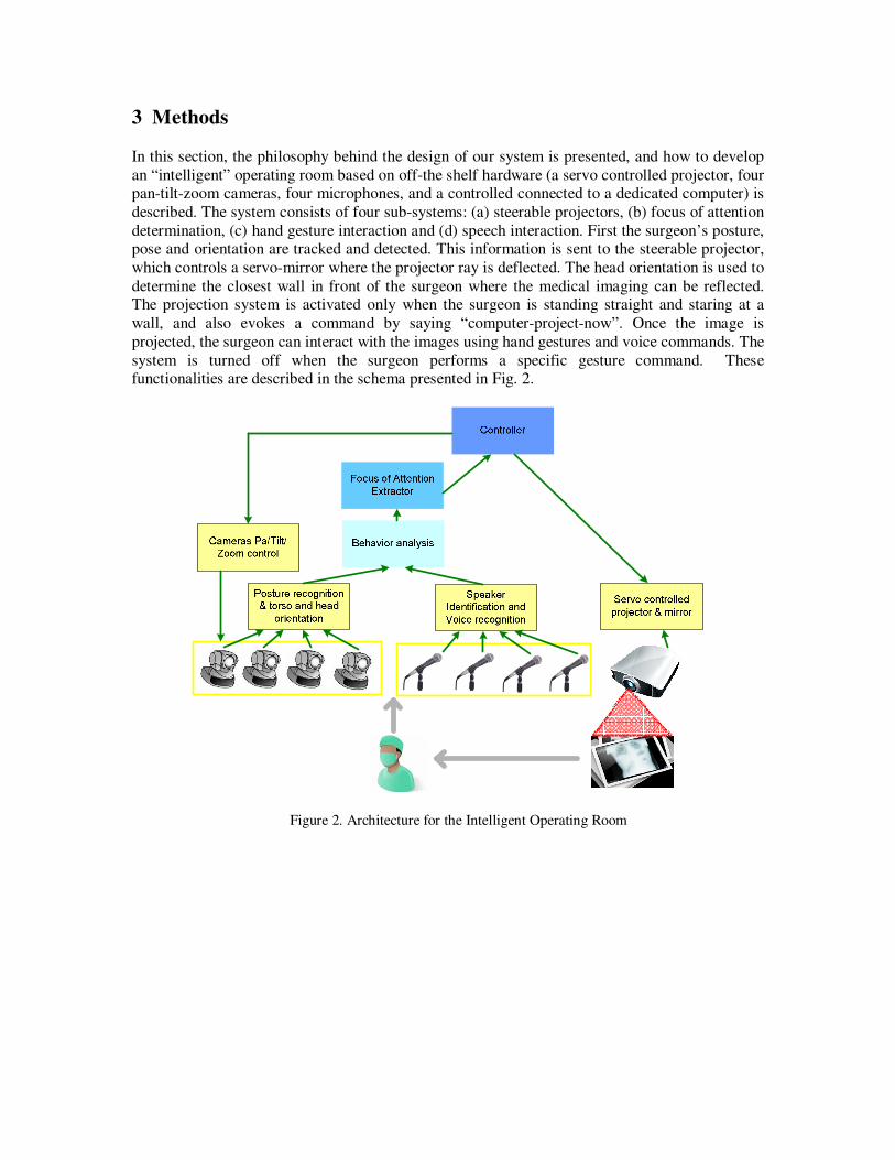
3 Methods
In this section, the philosophy behind the design of our system is presented, and how to develop
an “intelligent” operating room based on off-the shelf hardware (a servo controlled projector, four pan-tilt-zoom cameras, four microphones, and a controlled connected to a dedicated computer) is
described. The system consists of four sub-systems: (a) steerable projectors, (b) focus of attention
determination, (c) hand gesture interaction and (d) speech interaction. First the surgeon’s posture, pose and orientation are tracked and detected. This information is sent to the steerable projector,
which controls a servo-mirror where the projector ray is deflected. The head orientation is used to
determine the closest wall in front of the surgeon where the medical imaging can be reflected. The projection system is activated only when the surgeon is standing straight and staring at a
wall, and also evokes a command by saying “computer-project-now”. Once the image is
projected, the surgeon can interact with the images using hand gestures and voice commands. The
system is turned off when the surgeon performs a specific gesture command. These functionalities are described in the schema presented in Fig. 2.
Figure 2. Architecture for the Intelligent Operating Room
Assisting
surgeon
Non sterile
nurse
Anesthetist
Main surgeon
The main
control wall
Pan/Tilt/Zoom camera
PC Stations
with electronic
medical record system
PatientNon sterile nurses
Pan/Tilt/Zoom
camera
Pan/Tilt/Zoom
camera
Pan/Tilt/Zoom camera
microphone
microphone
microphone
microphone
Projected
Display
projector
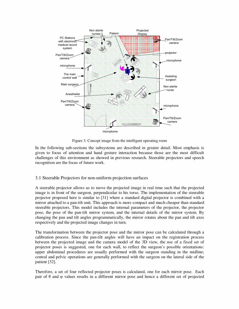
Figure 3. Concept image from the intelligent operating room
In the following sub-sections the subsystems are described in greater detail. Most emphasis is
given to focus of attention and hand gesture interaction because those are the most difficult
challenges of this environment as showed in previous research. Steerable projectors and speech recognition are the focus of future work.
3.1 Steerable Projectors for non-uniform projection surfaces
A steerable projector allows us to move the projected image in real time such that the projected image is in front of the surgeon, perpendicular to his torso. The implementation of the steerable
projector proposed here is similar to [31] where a standard digital projector is combined with a
mirror attached to a pan-tilt unit. This approach is more compact and much cheaper than standard steerable projectors. This model includes the internal parameters of the projector, the projector
pose, the pose of the pan-tilt mirror system, and the internal details of the mirror system. By
changing the pan and tilt angles programmatically, the mirror rotates about the pan and tilt axes
respectively and the projected image changes in turn.
The transformation between the projector pose and the mirror pose can be calculated through a
calibration process. Since the pan-tilt angles will have an impact on the registration process between the projected image and the camera model of the 3D view, the use of a fixed set of
projector poses is suggested, one for each wall, to reflect the surgeon’s possible orientations:
upper abdominal procedures are usually performed with the surgeon standing in the midline;
central and pelvic operations are generally performed with the surgeon on the lateral side of the patient [32].
Therefore, a set of four reflected projector poses is calculated, one for each mirror pose. Each pair of θ and φ values results in a different mirror pose and hence a different set of projected

corner points on the surface. The rigid transform from the reflected projector position for each of
those mirror poses is calculated using the procedure detailed in [33]. This requires the use of a camera to capture the projected image on the display surface, and assumes that the display surface
is uneven. Since in our case the display surface could potentially be any wall around the surgeon,
a pan/tilt/zoom camera dedicated to the projector is allocated, in addition to those used to capture
the surgeon postures. Let the display surface be represented in a 3D mesh. I try to find the transform that relates a given 2D pixel in the projector image plane (Z), to a 3D pixel in the
display surface (K), given that the place of the camera is so that the same point (V) appears in the
camera image as Z’. See Figure 4.
Figure 4. Camera and Projector 3D view geometry representation
Each point x=(x,y,w)T in the uneven display surface is a result of a ray originated in the center of
the projector Op traversing the projector plane in point ˆ ˆ( , )p pZ u v= , which in turn appears on the
image captured by the pan/tilt camera as point ˆ ˆ' ( , )c cZ u v= . The goal is to find the static parameter
f for every point relating the projector plane and the display surface. Knowing the internal
parameters of the projector, and the internal parameters of the camera and the homogeneity
matrix, [33] show that each sample point K in the 3D mesh follows can be found using (1):
1
ˆ
ˆ ˆ
1
p
p
x u
y p p f p
z
−
= − +
(1)
where p is the rotation 3x3 matrix, p̂ is the translation 3x1 vector, and f is the parametric scalar
value. It is possible to show that the parameter f can be estimated using traditional correspondence approaches, or using predictive methods such as particle filtering or Kalman
filters. In [33] a bank of kalman-filters were used to find the correspondences between the
projector pixel Z and the projected point K, one filter for each point Z. To reduce the complexity of the process, in every frame only one point Z is selected for matching. Once a point is selected
using a certain method (pseudo-randomly, distance based, feature detector), a patch around the
neighboring pixels is selected. This patch is cross-correlated with the predicted location on the

camera’s image, and close to the epipolar line. Once the new coordinate is found on the camera’s
image, the parameters for the 3D mesh are updated. This process corrects the projected image over the uneven surface so that curves and discontinuities are not perceived by the viewer,
however errors (maximum 6.78mm and mean 2.41mm) similar to [33] are expected. Sensitivity
studies based on these errors are the focus of future work.
3.2 Focus of attention determination
In this section, it is shown that by extracting the surgeon’s head orientation (which will be used as
a proxy for eye gaze) and torso posture and orientation (which are indicators of the action being performed), it may be possible to identify focus spatial offset and movement spatial offset which
are associated with attention shifts. In the first case, gaze orientation helps us to know where to
project the medical imagery (which wall to use as the display surface). In the second case, torso
position (standing straight or bent) indicates the surgeon’s possible intention: interaction with the patient, interaction with the medical imaging display or other activity.
Our method to extract head and torso position, posture and orientation is to look at each body
configuration as a different class: for example, the following notation describes the current state of a surgeon: s1 = {standing, torso 90 degrees, facing 0 degrees}. Thus, in this section, a multi-
class classifier based on parts-based models is described to find each of these configurations. The
approach is briefly described for object detection using single and multi-class detectors, in the context of US marine detection, as a case study only, but it is clear that the same approach can be
applied to any person. First, it is described the feature extraction process from patches (or parts)
and then the basic and shared classifiers are discussed.
3.2.1 Dictionary Creation
Initially, a dictionary is created from square sub-region patches extracted from a set of images per class, similar to [34]—these are also called “features”. Each image is convolved with a filter
from a bank of filters, grayscale normalized and re-scaled to a standard scale of 128x48 for the
standing and 64x48 for marines kneeling. Then patches are selected in x,y locations found using an interest point detector. In those locations patches are extracted from all the filtered images.
Each patch is associated with the place from where it was extracted, relative to the center of the
object. This location information is stored in two vectors containing the x,y offset distances respectively {lx, ly}, after applying a blurred delta function to them. Hence, each entry i in the
dictionary has the form vi={filter, patch, lx, ly, image no.}. If 8 images per class are used to create
the dictionary, 20 patches are extracted per image, a bank of 4 filters is used, and by classifying
into 8 classes, a total of 640 entries is obtained. The procedure is shown in Figure 5.

T
x yl l
I if iP
Figure 5. Dictionary entries: patches selected randomly (on the left image) are convolved with a bank of filters. The position of the patches is represented by the location matrix (right). Since the red patch is at
almost the same horizontal position and at the top, relative to the center, the position matrix has a bright
spot.
3.2.2 The feature vectors
The training set is created from a sample set of images excluding those used for the dictionary creation. For each of the eight (classes) objects I found all the images that include that type of
object. In each image, feature vectors are obtained using the following method:
1. Scale all the images in the training set so the object of interest is bounded by a rectangle of size 128x48 and 64x48 (region of interest, ROI) for standing and kneeling respectively, and
the images are not larger than 200x200.
2. For each image j normalized in scale, each entry i of the dictionary is applied to it: this means that this image is convolved with the filter in entry i, and convolved again with a Gaussian
to smooth the response. Next, it is cross-correlated with the patch in entry i, yielding a strong
response where this patch appears in the filtered image. Finally, the 1D filters lx and ly are applied
to the cross-correlated image, effectively “voting” for the object center. This is summarized in Eq. 2:
( )( , ) * * T
i i i x yv x y I f P l l= ⊗ (2)
Where * is the convolution operator, ⊗ is the normalized cross correlation operator, vi(x,y) is the feature vector entry i, f is a filter, P is a patch, and lx and ly are the x,y location vectors with respect to the center of the image respectively.
3. For each image in step 2, I extract feature vectors v(x,y). A positive sample vector is
obtained by retrieving v at the x,y coordinates in the center of the object. The negative training
samples are 20 vectors extracted from x,y locations outside the ROI with a local-maxima for function (2).
Each training feature vector is coupled with a class label (1 to 8) and -1 for negative samples.
For a sample set of 25 images per class, 4000 negative and 200 positive samples are obtained, with 640 features, see Figure 6.

if
⊗
I
iP T
x yl liv
, , ,1 , , ,2 , , ,3 , , ,( , ) [ , , ,..., ]i i x y i x y i x y i x y Nv x y ν ν ν ν=
, ', ',1 , ', ',2 , ', ',3 , ', ',( ', ') [ , , ,..., ]
i i x y i x y i x y i x y Nv x y ν ν ν ν=
Figure 6. Positive and negative vector set creation using the dictionary entries and sampling the center out
of the silhouette points. Each sampled point, is a vector, where an entry j in the vector represents the
number of votes assigned by patch Pi.
3.2.3 Sharing the features effectively
In this section I briefly describe the joint boosting algorithm used for multi-class multi-view object detection. For a more detailed discussion, refer to [35].
A boosting algorithm is an additive model where weak learners are sequentially added to form a
strong classifier. For the multiclass case, the strong learner is defined as:
1
( , ) ( , )M
m
m
H v c h v c=
=∑
(3)
Where v is the input feature vector, M is the number of boosting iterations, c is a specific class and H(v,c)=log P(zc=1|v)/P(zc = -1|v) is the logistic function where z is the membership label
(±1). When the expectation is replaced by an average over the training data, the cost function can
be written as:
( )2
1 1
( , )C N
c c
wse i i m i
c i
J w z h v c= =
= −∑∑
(4)
Where N is the number of training vectors, c
iw are the weights for sample i and for class c, c
iz is the
membership label for sample i for class c (±1). The weak shared learner, also called, regression
“stump” is defined for the multiclass in (5):
( )
( , ) ( )
( )
f
S i
f
m S i
c
S
a if v and c S n
h v c b if v and c S n
k if c S n
θ
θ
> ∈
= ≤ ∈ ∉
(5)
where vf is the component fth
from the vector v, θ is a threshold, δ is the indicator function, aS
and bS are regression parameters. S(n) is a subset of the classes labels. Each round of boosting
consists of selecting the shared “stump” and the shared feature f that minimizes (3), from the
subset of classes S(n), in the following stated procedure: Pick a subset of classes S(n). Search all the components f of the feature vector v, for each component, search over all the discrete values
of θ and for each couple {f, θ}, find the optimal regression parameters aS and bS using (6-8).
Finally, select {f, θ, aS, bS} that minimizes (4).
( )( )
( )( )
( )
,
c c f
i i ic S n i
S c f
i ic S n i
w z va f
w v
δ θθ
δ θ
∈
∈
>=
>
∑ ∑∑ ∑
(6)
( )( )
( )( )
( )
,
c c f
i i ic S n i
S c f
i ic S n i
w z vb f
w v
δ θθ
δ θ
∈
∈
≤=
≤
∑ ∑∑ ∑
(7)
c c
i ic i
c
ii
w zk
w=∑∑
(8)
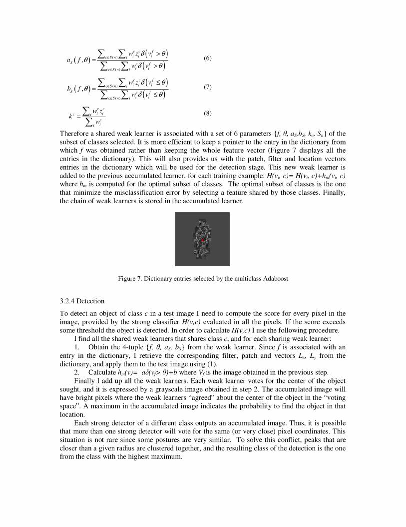
Therefore a shared weak learner is associated with a set of 6 parameters {f, θ, aS,bS, kc, Sn} of the
subset of classes selected. It is more efficient to keep a pointer to the entry in the dictionary from which f was obtained rather than keeping the whole feature vector (Figure 7 displays all the
entries in the dictionary). This will also provides us with the patch, filter and location vectors
entries in the dictionary which will be used for the detection stage. This new weak learner is
added to the previous accumulated learner, for each training example: H(vi, c)= H(vi, c)+hm(vi, c) where hm is computed for the optimal subset of classes. The optimal subset of classes is the one
that minimize the misclassification error by selecting a feature shared by those classes. Finally,
the chain of weak learners is stored in the accumulated learner.
Figure 7. Dictionary entries selected by the multiclass Adaboost
3.2.4 Detection
To detect an object of class c in a test image I need to compute the score for every pixel in the
image, provided by the strong classifier H(v,c) evaluated in all the pixels. If the score exceeds
some threshold the object is detected. In order to calculate H(v,c) I use the following procedure. I find all the shared weak learners that shares class c, and for each sharing weak learner:
1. Obtain the 4-tuple {f, θ, aS, bS} from the weak learner. Since f is associated with an
entry in the dictionary, I retrieve the corresponding filter, patch and vectors Lx, Ly from the
dictionary, and apply them to the test image using (1). 2. Calculate hm(v)= aδ(vf> θ)+b where Vf is the image obtained in the previous step.
Finally I add up all the weak learners. Each weak learner votes for the center of the object
sought, and it is expressed by a grayscale image obtained in step 2. The accumulated image will have bright pixels where the weak learners “agreed” about the center of the object in the “voting
space”. A maximum in the accumulated image indicates the probability to find the object in that
location.
Each strong detector of a different class outputs an accumulated image. Thus, it is possible that more than one strong detector will vote for the same (or very close) pixel coordinates. This
situation is not rare since some postures are very similar. To solve this conflict, peaks that are
closer than a given radius are clustered together, and the resulting class of the detection is the one from the class with the highest maximum.
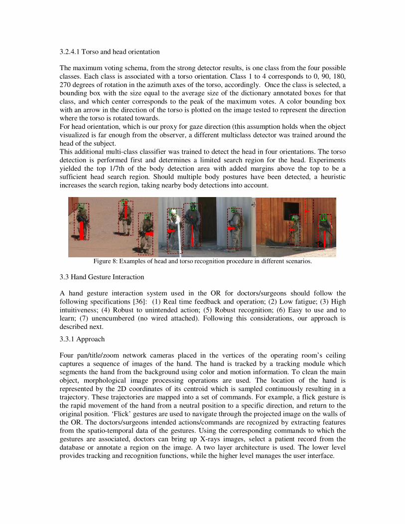
3.2.4.1 Torso and head orientation
The maximum voting schema, from the strong detector results, is one class from the four possible
classes. Each class is associated with a torso orientation. Class 1 to 4 corresponds to 0, 90, 180,
270 degrees of rotation in the azimuth axes of the torso, accordingly. Once the class is selected, a bounding box with the size equal to the average size of the dictionary annotated boxes for that
class, and which center corresponds to the peak of the maximum votes. A color bounding box
with an arrow in the direction of the torso is plotted on the image tested to represent the direction where the torso is rotated towards.
For head orientation, which is our proxy for gaze direction (this assumption holds when the object
visualized is far enough from the observer, a different multiclass detector was trained around the
head of the subject. This additional multi-class classifier was trained to detect the head in four orientations. The torso
detection is performed first and determines a limited search region for the head. Experiments
yielded the top 1/7th of the body detection area with added margins above the top to be a sufficient head search region. Should multiple body postures have been detected, a heuristic
increases the search region, taking nearby body detections into account.
Figure 8: Examples of head and torso recognition procedure in different scenarios.
3.3 Hand Gesture Interaction
A hand gesture interaction system used in the OR for doctors/surgeons should follow the
following specifications [36]: (1) Real time feedback and operation; (2) Low fatigue; (3) High
intuitiveness; (4) Robust to unintended action; (5) Robust recognition; (6) Easy to use and to learn; (7) unencumbered (no wired attached). Following this considerations, our approach is
described next.
3.3.1 Approach
Four pan/title/zoom network cameras placed in the vertices of the operating room’s ceiling
captures a sequence of images of the hand. The hand is tracked by a tracking module which segments the hand from the background using color and motion information. To clean the main
object, morphological image processing operations are used. The location of the hand is
represented by the 2D coordinates of its centroid which is sampled continuously resulting in a trajectory. These trajectories are mapped into a set of commands. For example, a flick gesture is
the rapid movement of the hand from a neutral position to a specific direction, and return to the
original position. ‘Flick’ gestures are used to navigate through the projected image on the walls of
the OR. The doctors/surgeons intended actions/commands are recognized by extracting features from the spatio-temporal data of the gestures. Using the corresponding commands to which the
gestures are associated, doctors can bring up X-rays images, select a patient record from the
database or annotate a region on the image. A two layer architecture is used. The lower level provides tracking and recognition functions, while the higher level manages the user interface.

As opposed to field conditions, may raise challenges related to limited lighting conditions and
unfixed environments. We plan to address this problem using simulation under operating room conditions to obtain a better assessment of system’s performance.
3.3.2 Hand Segmentation and Tracking
A 2D histogram is generated in real-time during ‘calibration’ from the doctor’s hand. The
calibration process is initiated when the user places his hand slowly into a boundary without touching the screen. This, in turn, is used to build a hand color distribution model. A pixel at
location (x, y) is converted to the probability that the pixel is classified as a hand (or gloved
hand), in any frame using the 2D histogram lookup table created earlier (Figure 9).
Figure 9. User hand skin color calibration
In order to avoid false motion clues originated by non-hand motion in the calibration phase, a background maintenance procedure was developed. First, an initial image of the background is
created. Changes are detected background differencing. When this difference is coherently
significant, I assume that the present object is a hand. The background stored image is updated
using a running smoothed average (9).
),()1(),(),( 1 jiBjifjiB kk −×−+×= λλ (9)
Where, Bk is the updated stored background image at frame k, Bk-1 is the stored background
image at frame k-1, λ is the smoothing coefficient (regulates update speed), f(i, j) is the current background image at frame k.
To track the hand, CAMSHIFT is used [37]. It uses a probability distribution image comprised of
pixels representing hand colors. This hand image is created from a 2D hue-saturation skin color histogram [38]. A histogram is used as a look-up-table to convert the acquired camera images of
the hand into corresponding hand pixels, a process known as back projection. In the original
CAMSHIFT algorithm the probability of a pixel belonging to the hand is determined by the
grayscale value of the pixel only. In lieu of using color probability alone, I modify it with motion information according to (2) to represent a hand pixel probability. The relative weights between
color and motion are shifted according to the amount of motion in the scene resulting in an
adaptive fusion system. Using the centroid and size of the hand pixel an iterative procedure based on a generalization of the mean shift algorithm [39]. is used to update the tracking window at
each frame. Thresholding to black and white followed by morphological operations is used to
obtain a single component for further processing to classify the gestures.
3.3.3 Operation
The gesture interface can be used to browse medical databases and manipulate the projected imagery such as X-rays and MRIs. The finite state machine in Figure 10 illustrates the operational
modes with the gesture interface. After the calibration procedure dynamic gestures are used to
browse images and hand poses are used to switch between modes of operation. The central area
in the middle of the frame is called the "neutral area", see Figure 11.
When a doctor decides to perform a specific operation on a medical image, he/she places the hand
in the ‘neutral area’ momentarily, which will be followed by the zoom posture or rotation pose
gesture.
Start
Calibration
Mode Detector
Stop
FlickGestures
Left Right Up Down
SweepGesture
Closer Further
Track SSI
Rotate
Browse Zoom Rotate
Sleep
Figure 11. State machine for the gesture-based medical browser
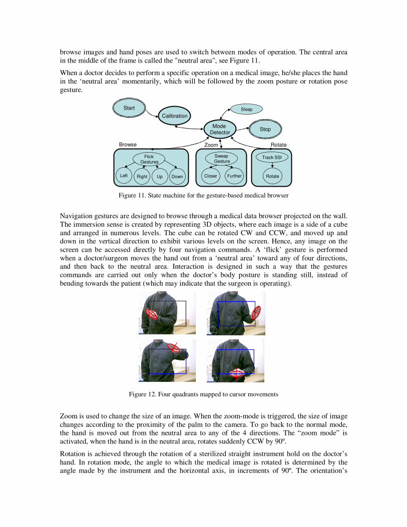
Navigation gestures are designed to browse through a medical data browser projected on the wall.
The immersion sense is created by representing 3D objects, where each image is a side of a cube
and arranged in numerous levels. The cube can be rotated CW and CCW, and moved up and down in the vertical direction to exhibit various levels on the screen. Hence, any image on the
screen can be accessed directly by four navigation commands. A ‘flick’ gesture is performed
when a doctor/surgeon moves the hand out from a ‘neutral area’ toward any of four directions, and then back to the neutral area. Interaction is designed in such a way that the gestures
commands are carried out only when the doctor’s body posture is standing still, instead of
bending towards the patient (which may indicate that the surgeon is operating).
Figure 12. Four quadrants mapped to cursor movements
Zoom is used to change the size of an image. When the zoom-mode is triggered, the size of image
changes according to the proximity of the palm to the camera. To go back to the normal mode, the hand is moved out from the neutral area to any of the 4 directions. The “zoom mode” is
activated, when the hand is in the neutral area, rotates suddenly CCW by 90º.
Rotation is achieved through the rotation of a sterilized straight instrument hold on the doctor’s
hand. In rotation mode, the angle to which the medical image is rotated is determined by the angle made by the instrument and the horizontal axis, in increments of 90º. The orientation’s

instrument can be found using the Probabilistic Hough Transform (pHT). Only lines on the
nearby proximity of the hand are considered (2.5 times around the interaction window).
To avoid the recognition of unintentional gestures, when the doctor wants to stop temporarily the
operation of the hand gesture recognition system, he can either gaze down towards the patient, or
user moves the hand to the lowest part of the screen, keeping it within the screen boundaries. To
return to the “normal mode” a wake up gesture is used whereby the user waves the hand over the small rectangle in the upper left corner of the screen. This is useful when the doctor wishes to
discuss details on the projected image without being “tracked” by the system.
3.4 Speech Interaction
One of the main goals regarding the intelligent operating room is twofold: (a) identify the user
(ID tagging) automatically and (b) to recognize spoken utterances. The first goal, on one hand grants the user (either a nurse or the main surgeon) access to digital patient records and medical
imaging tools according to the privileges that have been assigned to him, and on the second hand
allows the room to keep track of the subject when ambiguity occurs due to light changing, occlusions and merging of several subjects. If I want to allow only the surgeon to manipulate and
annotate the patient’s medical images during surgery, the operation will be activated only when
spoken utterances are recognized by the room as belonging to the surgeon’s voice. To achieve
this goal, the users will be required to say the word “login” [38] and compared to prototype feature vectors using some distance measure, such as maximum likelihood. For every participant
in the OR, a profile is created and matched to the existing profiles in order to assess the level of
permission that needs to be granted. The second goal involves the recognition of words and sentences using off-the-shelf voice
recognition software, called “DragonDictate”, which can explicitly build continuous speech and
context-free recognition grammars [39]. To transmit the speech to the recognition module, multiple microphones are used. Since I want to keep the sterility requirements, the microphones
are not attached to the doctors. Instead, the microphones are set-up in key locations on the OR’s
ceiling.
Voice commands are used to evoke functions that are very difficult to map to hand gestures since there is no natural association between them. For example, to retrieve medical images of the
patient being operated, the surgeon can say the patient’s name. To discriminate between
environment noise, which can mistakenly being recognized as a command, the user has to start the command by saying “system” shortly followed by the command to be carried out. This
approach was suggested in [39] in the context of smart rooms, where the vision recognition and
audio recognition modules are independent, and hence it fits the requirements for the operation
room. Environment noise can still be too high and interfere with the interaction. We plan to test these scenarios in further work.
4 Conclusions
This work presents one possible application for smart rooms: the intelligent, collaborative
operating room. By monitoring the surgeon’s activities while performing surgery, the system can
collaborate with her by displaying relevant medical imaging information in a convenient location
in the OR. The OR depends on the surgeon’s body language as the essential key to understanding his focus of attention. One goal of the suggested approach is to use computer vision techniques to
detect body postures and gaze to determine focus of attention. Smart projectors combined with
computer graphics techniques are used to project medical imaging in front of the surgeon, based on the knowledge provided by the posture recognizer. Person-detection with simultaneous human
body posture recognition is achieved using parts-based models and a multiclass boosting
approach: each body part is matched with the image captured by the camera, and each part votes

for the center of the person. Focus of attention is assessed by simultaneous detection of the
surgeon’s posture and orientation. Detection and classification are possible since features of different human postures have shared subspaces as opposed to the non-person class. One
challenge here is the focus on postures that cannot be easily distinguished by their aspect ratio or
silhouette, but rather require a bottom-up approach. Parts-based detection does not require
explicit models, nor the labeling of individual body parts. The detection and posture classifications are performed in a single pass over the image, and the strength of the recognition is
proportional to the ensemble of votes from parts patches.
A vision-based system is used for interaction with the medical images,. It recognizes the
surgeon’s gestures in real-time which are used to browse, zoom and rotate the images projected
on the wall in front of him. The system is user independent since it is calibrated using a multi-modal two step procedure: first the user’s ID is recognized using a voice identification system,
then cameras are used to model the gamut of colors of the surgeon’s hand. Camshift is used to
track the hand, which allows dynamic hand gesture navigation control. The decision to use hand
gestures as the main modality of interaction is based on previous work done by the author [25], where it was shown that hand gesture interaction in the operating room is the preferred modality
of interaction by the doctors in the OR, due to their proficiency at using the hand as their main
tool of work. Hand gestures offer the following benefits: (i) Ease of use: - Surgeons are already quite proficient in their use of hands as a primary work tool, (ii) Rapid reaction: - hand gesture
commands are intuitive and fast, (iii) Unencumbered: - does not require the surgeon to be wired
to any device, and (iv) Sterility: - non contact interaction.
Issues related to image processing performance algorithm under unfixed environments require
further analysis and more robust vision algorithms. For example, in [25] we used only one frontal
camera, and in the current research I implement four. It is not likely that the surgeon will be in front of any of these cameras. To correct for this, the image need to be re-projected using the
homography matrix found in the calibration process. Still some areas may remain occluded. In
future work these challenges will be addressed and a simulation framework is going to be adopted in order to quantitatively validate the hypothesis suggested in this work.
Surgeons must command a high level of cognitive and motor skills in order to complete their
tasks successfully. Previous research has shown that during the performance of a specific task, most gaze changes are related to the task-oriented visual search. Distractions may have an
adverse effect on task performance since they compete with the mental resources allocated for
that task. I specifically address the problem of the distraction to the surgeon, (or shift of focus) required for closer examination of medical imaging. I alleviate this situation by displaying the
medical imaging in a convenient size right in front of the surgeon, automatically detecting his
current orientation.
In more general terms, I believe that hand gesture, body posture and voice recognition can be
used to help an intelligent system understand the context of the work being performed in an
operating room. Intelligent rooms equipped with hand gesture, body posture and voice recognition capabilities can assist surgeons in the execution of time-or-safety critical tasks, while
providing him/her with natural, intuitive and easy to use interaction modalities.
References
[1] T.R. Hansen ,Focus Shift Analysis in the operating theatre,. 2004. Source:
http://www.pervasive-interaction.org/publications/Focus_shift.pdf
[2] J. Graydon, M. Eysenck, Distraction and cognitive performance, Eur J Cogn
Psychol.;1(2):161-179. 1989
[3] V. Weerdesteyn, A. Schillings, G. Van Galen, D. Duysens, Distraction affects the
performance of obstacle avoidance during walking, J Motor Behavior. 35(1):53-63, 2003.
[4] K. H. Goodell, C. G. Cao, S. D. Schwaitzberg, Effects of cognitive distraction on
performance of laparoscopic surgical tasks, J Laparoendosc Adv Surg Tech A. Apr;16(2):94, 2006.
[5] R. M. Satava, Disruptive visions: The operating room of the future. Surgical
endoscopy, vol. 17, no1, pp. 104-107, 2003.
[6] J. V. Sutherland, W. J. Van den Heuvel, T. Ganous , M. M. Burton, A. Kumar, Towards an
Intelligent Hospital Environment: Adaptive Workflow in the OR of the Future, Stud Health
Technol Inform.118:278-312, 2005.
[7] P. Wellner,The DigitalDesk Calculator: Tangible Manipulation on a Desk Top Display, Proceedings of UIST’91. pp.27-33. 1991.
[8] W. Newman, P. Wellner, A Desk Supporting Computer based interaction with paper, Proceedings of the Conference on Human Factors in Computing Systems (CHI’92). p587-
592. 1992.
[9] Microsoft Surface. Available online: www.microsoft.com/surface/
[10] R. A. Brooks, The Intelligent Room Project, Proceedings of the Second International
Cognitive Technology Conference (CT'97), Aizu, Japan, August 1997.
[11] K. S. Huang and M. M. Trivedi, Video Arrays for Real-Time Tracking of Persons, Head
and Face in an Intelligent Room, Machine Vision and Applications, Special Issue, Jun. 2003.
[12] M. Nicolescu and G. Medioni, Electronic pan-tilt-zoom: a solution for intelligent room systems, Proc. ICME'2000, 2000.
[13] J. C. Terrillon, A. Piplr, Y. Niwa, K. Yamamoto, Robust Face Detection and Japanese Sign
Language Hand Posture Recognition for Human Human-Computer Interaction in an “Intelligent” Room, In Proc. Int'l Conf. Vision Interface, 2002.
[14] N. Dimakis, J. K. Soldatos, L. Polymenakos, P. Fleury, D. Curin, Jan, J. Kleindienst, Integrated development of context-aware applications in smart spaces, Pervasive
Computing, IEEE 7 (4), 71-79, 2008.
[15] T Skordas, G Metakides, Major Challenges in Ambient Intelligence, Studies in Informatics
and Control, Vol.12, No.2, June 2003 Page 3. 2.3.
[16] J. P. Tardif, S. Roy, M. Trudeau, Multi-projectors for arbitrary surfaces without explicit
calibration nor reconstruction, In Proceedings of Fourth International Conference on 3-D
Digital Imaging and Modeling. 3DIM 2003.. pp. 217-224. 2003.
[17] A. Griesser and L. V. Gool, Automatic Interactive Calibration of Multi-Projector-Camera
Systems, Proceedings of the 2006 Conference on Computer Vision and Pattern
Recognition Workshop, 8, 2006.
[18] I. Mitsugami, N. Ukita, M. Kidode,.`Displaying a Moving Image By Multiple Steerable
Projectors', IEEE International Workshop on Projector-Camera Systems (Procams2007), 2007.
[19] Z. Jiang, Y. Mao, B. Qin and B. Zang, A High Resolution Video Display System by Seamlessly Tiling Multiple Projectors, IEEE International Conference on Multimedia and
Expo, 2007.
[20] E. Bhasker, R. Juang, A. Majumder, Registration Techniques for Using Imperfect and Par tially Calibrated Devices in Planar Multi-Projector Displays, IEEE Transactions on
Visualization and Computer Graphics, 13:6, 1368-1375, 2007.
[21] J. Summet, M. Flagg, TJ. Cham, JM. Rehg and R. Sukthankar, Shadow Elimination and
Blinding Light Suppression for Interactive Projected Displays,IEEE Transactions on
Visualization and Computer Graphics, 13:3,508-517, 2007.
[22] T. Johnson, G. Welch, H. Fuchs, E. La Force, H. Towles, A Distributed Cooperative
Framework for Continuous Multi-Projector Pose Estimation in Proceedings IEEE VR
2009, 2009.
[23] A. Nishikawa, T. Hosoi, K. Koara, D. Negoro, A. Hikita, S. Asano, H. Kakutani, F.
Miyazaki, M. Sekimoto, M. Yasui, Y. Miyake, S. Takiguchi, and M. Monden. FAce MOUSe: A Novel Human-Machine Interface for Controlling the Position of a Laparoscope,
IEEE Trans. on Robotics and Automation, 19:5, 825-841, 2003.
[24] C. Graetzel, T.W. Fong, S. Grange, and C. Baur, A non-contact mouse for surgeon-
computer interaction, Technology and Health Care, 12:3, 245-257, 2004.
[25] J. Wachs, H. Stern, Y. Edan, M. Gillam, C. Feied, M. Smith, and J. Handler, A hand
gesture sterile tool for browsing MRI images in the OR, Journal of the American Medical
Informatics Association. 15(3), 2008.
[26] P. Lukowicz, A. Timm-Giel, H. Lawo, O. Herzog, WearIT@work: Toward Real-World
Industrial Wearable Computing, IEEE Pervasive Computing. 6:4,8-13, 2007.
[27] Y. Kuno, T. Murashima, N. Shimada, and Y. Shirai, Intelligent Wheelchair Remotely
Controlled by Interactive Gestures, In Proceedings of 15th Intl. Conf. on Pattern
Recognition, 4,672-675, 2000.
[28] T. Starner, J. Auxier, D. Ashbrook, and M. Gandy. The Gesture Pendant: A Self-
illuminating, Wearable, Infrared Computer Vision System for Home Automation Control and Medical Monitoring, In 4th Intl. Symposium on Wearable Computers, 87-94, 2000.
[29] D. A. Becker and A. Pentland, Staying Alive: A Virtual Reality Visualization Tool for
Cancer Patients, Proc. of the AAAI'96 Workshop on Entertainment and Alife/AI, 1996.
[30] R. Boian, R. Sharma, C. Han, A. Merians, G Burdea, S. Adamovich, M. Recce, M.
Tremaine, H. Poizner, Virtual reality-based post-stroke hand rehabilitation,Studies in
Health and Technology Information, 85, 64-70, 2002.
[31] M. Ashdown and Y. Sato, Steerable projector calibration, Proceedings of the 2005 IEEE
Computer Society Conference on Computer Vision and Pattern Recognition (CVPR'05),
2005.
[32] E. Moschos, R. Coleman, Acquiring laparoscopic skill proficiency: Does orientation
matter?, American Journal of Obstetrics and Gynecology, 191:5, 1782-1787, 2004.
[33] R. Yang and G. Welch.,Automatic and Continuous Projector Display Surface Estimation Using Every-Day Imagery, 9th International Conference in Central Europe on Computer
Graphics, Visualization and Computer Vision, 2001.

[34] K. Murphy, A. Torralba, D. Eaton, W. T. Freeman,Object detection and localization using
local and global features, Lecture Notes in Computer Science. Sicily workshop on object
recognition, 2005.
[35] J. Wachs, D. Goshorn and M. Kölsch, Recognizing Human Postures and Poses in Monocular Still Images, In Proceeding of the International Conference on Image
Processing, Computer Vision, and Signal Processing. (IPCV09) Las Vegas, Nevada. July
2009.
[36] J. Wachs, H. Stern, Y. Edan, M. Gillam, C. Feied, M. Smith, and J. Handler, A Real-Time
Hand Gesture Interface for a Medical Image Guided System, International Journal of
Intelligent Computing in Medical Sciences and Image Processing, 1:3:1, 175-185, 2008.
[37] G. R. Bradski, Computer vision face tracking for use in a perceptual user interface, Intel
Technical Journal, 1-15, 1998.
[38] S. T. Shivappa, M. M. Trivedi, and B. D. Rao, Hierarchical audio-visual cue integration
framework for activity analysis in intelligent meeting rooms, IEEE CVPR 2009, 2009.
[39] M. Coen, Design principles for intelligent environments, In Proc. of AAAI, Madison,
Wisconsin, 1998.
Author’s Name: Juan P. Wachs
University: Purdue University Department: School of Industrial Engineering
Address: 315 N. Grant St., W. Lafayette, IN 47907-2023 USA
E-mail: [email protected]
Received: Accepted:


![A Gaze Gesture-Based User Authentication System to ...library.usc.edu.ph/ACM/CHI 2017/2exab/ea1978.pdfCamera, 2 - Authentication interface, 3 - Eye tracker]. Figure 2: Gaze gesture-based](https://static.fdocuments.net/doc/165x107/5faaaba9b03f6d34b2222ac9/a-gaze-gesture-based-user-authentication-system-to-20172exabea1978pdf-camera.jpg)
![U-Remo: Projection -assisted Gesture Control for Home ...siio.jp/projects/papers/chi2014_uremo.pdf · using eye gaze control [2]. The advantage of gaze operation compared with gesture](https://static.fdocuments.net/doc/165x107/5fc38b12cd39280f315d3590/u-remo-projection-assisted-gesture-control-for-home-siiojpprojectspaperschi2014uremopdf.jpg)