Gaylord Tilter 299 and 120 Series - Conair
21
www.conairgroup.com Corporate Office: 724.584.5500 l Instant Access 24/7 (Parts and Service): 800.458.1960 l Parts and Service: 814.437.6861 U SER GUIDE UGC066- 0117 Gaylord Tilter 299 and 120 Series Conair has a policy of continuously developing all equipment and accessories. Therefore, we must reserve the right to make changes to Conair models from time to time. No claims can be made based on the information and illustrations contained in this manual.
Transcript of Gaylord Tilter 299 and 120 Series - Conair

www.conairgroup.com
Corporate Office: 724.584.5500 l Instant Access 24/7 (Parts and Service): 800.458.1960 l Parts and Service: 814.437.6861
U S ER G UI D E
UGC066-0117
Gaylord Tilter299 and 120 Series
Conair has a policy of continuously developing all equipment and accessories. Therefore, we must reserve the right to make changes to Conair models from time to time. No claims can be made based on the information and illustrations contained in this manual.
Rev F1/25/17
2
1. Introduction .................................................................................................................. 31.1 Using This Manual .................................................................................................... 3
2. Description of Equipment .......................................................................................... 42.1 Specifications ............................................................................................................ 41.2 Equipment Details ..................................................................................................... 4
3. Safety ............................................................................................................................. 53.1 User/Owner Responsibility ...................................................................................... 53.2 Safety Guidelines ...................................................................................................... 53.3 Material Safety .......................................................................................................... 63.4 Energy Isolation ........................................................................................................ 6
4. Installation .................................................................................................................... 74.1 Pre-Shipment Planning ............................................................................................ 74.2 Inspection of Shipment ............................................................................................. 74.3 Installation Guidelines .............................................................................................. 74.4 Purchased Component Installation and Setup .......................................................... 84.5 RetrofitPackages ...................................................................................................... 8
5. Sequence of Operation ............................................................................................... 95.1 Operation .................................................................................................................. 95.2 Loading ..................................................................................................................... 95.3 Foot pedal operation ................................................................................................. 95.4 Hand valve operation ................................................................................................ 9
6. Maintenance ...............................................................................................................106.1 Considerations ........................................................................................................ 106.2 Maintenance Schedule ............................................................................................ 106.3 Airbag Replacement ............................................................................................... 10
7. Caster Retrofit Package ............................................................................................127.1 Installation .............................................................................................................. 127.2 Operation ................................................................................................................ 13
8. Safety Ratchet Retrofit Package ..............................................................................148.1 Installation .............................................................................................................. 14
9. Warranty ......................................................................................................................1610. Appendix .....................................................................................................................17
10.1 Mechanical Drawings ............................................................................................. 1710.2 Controls Schematics ............................................................................................... 17
Contents
Rev F1/25/17
3
1. IntroductionAt Conair, we provide our customers with tools to improve product quality, increase safety and hygiene in the manufacturing process, and reduce operating costs. This manual is an extension of our commitment to the success of our customers and the safe, optimal performance of our systems.
1.1 Using This Manual
Thepurposeofthismanualistoprovidesystem-specificinformationthatcanbeusedtotrainpersonneland generate in-house procedures for safely operating and maintaining this system. This manual is intended for users with a basic understanding of industrial/automated equipment.
1.1.1 Symbols
The following symbols are used in this manual to identify information on hazards and prevention, as well as protection of the system.
DANGER: Indicates a hazardous situation which, if not avoided, will result in death or serious injury.
WARNING: Indicates a hazardous situation which, if not avoided, could result in death or serious injury.
CAUTION: Indicates a hazardous situation which, if not avoided, could result in minor or moderate injury.
NOTICE: Indicates a practice that is not related to personal injury.
1.1.2 Terms and Definitions
The list below contains common terms and abbreviations used in this manual, along with definitions.
Term DefinitionSupplier ConairUser, Owner Individual or corporation that utilizes
and/or owns the systemPersonnel, Operator Individual employed on behalf of or by
the user/ownerHazard Potential cause of harm In-house Conducted from within your organizationPPE Personal Protective EquipmentANSI Approved American National StandardOSHA Occupational Safety & Health
Administration
Rev F1/25/17
4
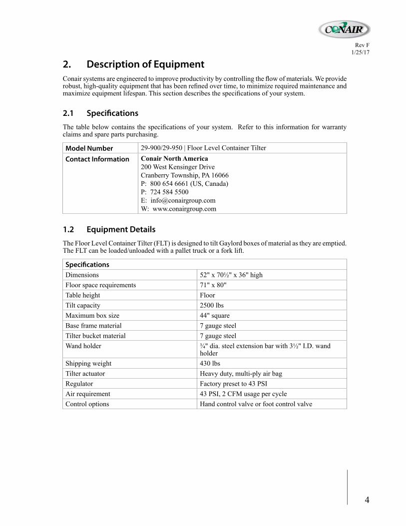
Model Number 29-900/29-950 | Floor Level Container TilterContact Information Conair North America
200 West Kensinger Drive Cranberry Township, PA 16066P: 800 654 6661 (US, Canada)P: 724 584 5500E: [email protected]: www.conairgroup.com
Specifications Dimensions 52" x 70½" x 36" highFloor space requirements 71" x 80"Table height FloorTilt capacity 2500 lbsMaximum box size 44" squareBase frame material 7 gauge steelTilter bucket material 7 gauge steelWand holder ¾" dia. steel extension bar with 3½" I.D. wand
holderShipping weight 430 lbsTilter actuator Heavy duty, multi-ply air bagRegulator Factory preset to 43 PSIAir requirement 43 PSI, 2 CFM usage per cycleControl options Hand control valve or foot control valve
1.2 Equipment Details
The Floor Level Container Tilter (FLT) is designed to tilt Gaylord boxes of material as they are emptied. The FLT can be loaded/unloaded with a pallet truck or a fork lift.
2. Description of EquipmentConairsystemsareengineeredtoimproveproductivitybycontrollingtheflowofmaterials.Weproviderobust,high-qualityequipmentthathasbeenrefinedovertime,tominimizerequiredmaintenanceandmaximizeequipmentlifespan.Thissectiondescribesthespecificationsofyoursystem.
2.1 Specifications
Thetablebelowcontains thespecificationsofyoursystem. Refer to this informationforwarrantyclaims and spare parts purchasing.
Rev F1/25/17
5
3. SafetyAlways observe the safety precautions below, as well as in-house guidelines and federal, state, and local codes/standards. Read and understand all operating information and drawings/schematics before using this system.
3.1 User/Owner Responsibility
Above all, it is the responsibility of the user/owner to provide a safe working environment, including: • Compliance with all applicable health and safety codes/standards• Training for all personnel• Provision of appropriate PPE• Proper maintenance and operation of systems/equipment
3.2 Safety Guidelines
Ensure that the motor and frame of the system are grounded in accordance with all federal, state, and local codes/standards.Do not use a damaged electrical supply cable or a connection that it not approved by federal, state, and local codes/standards.Your Conair equipment must have a lockable isolation/relief device for each energy source. If these device(s) are not purchased from Conair, the customer must provide and install a lockable isolation/relief device for each energy source (in accordance with federal, state, and local codes/standards).All moving parts of this system must be fully covered by guarding. Conair offers a full system safety cage as a protective measure. It is the responsibility of the user/owner to select and implement the appropriate protective equipment (in accordance with federal, state, and local codes/standards).DO NOT operate this system with any of the safety guards or devices removed, defeated, or bypassed. Operate this system only when all safety guards/devices are in place and operational. DO NOT operate this system until you have been fully trained.Installation,service,andmaintenanceofthissystemmustonlybeperformedbyexperienced,qualifiedpersonnel. DO NOT wear any items that could get caught in the moving parts of this system.Never place any part of your body under or near rotating members or moving parts of machinery.Isolate energy and perform your lockout/tag-out procedure before a adjusting, servicing, repairing, maintaining, or clearing blockages from this system. Refer to the Energy Isolation section for additional information.Perform scheduled inspections and maintenance of the system (refer to the Maintenance section for additional information). Repair/replace defective components immediately, and do not operate the system until it is in proper operating condition.DO NOT wash down electric motors (unless wash-down rated). The customer is responsible for evaluation of the noise level emitted by the equipment and provision of appropriate PPE, as required. If any safety decal is damaged or not readable, shut down the system and do not resume operation until the decal is replaced. For current pricing and delivery, contact Conair at 800 654 6661 or e-mail [email protected] to reorder safety decals.
Rev F1/25/17
6
3.3 Material SafetyDANGER: Donotprocessflammable, explosive, toxic,orotherwisehazardousmaterialswithoutfirstperforming an appropriate Process Hazard Analysis (PHA).
Conaircannotbeanexpertinthechemicalandbiologicalpropertiesoftheinfinitenumberofmaterialsthatcould be handled by this equipment. This equipment is not designed to safely process hazardous materials unless additional precautions are taken.
Beforeprocessinganymaterialsthatareorcanreacttobecomeflammable,explosive,toxic,orotherwisehazardous, the user/owner must perform a thorough risk assessment and Process Hazard Analysis of the entire process, including contingency plans for dealing with processing errors and upset conditions.
3.4 Energy IsolationDANGER: Electrical enclosures contain hazardous voltage that will result in electrical shock or burn. Turn off and lock out system before servicing.
DANGER:Equipmentwithintheelectricalenclosureposesashockandarcflashhazardthatmaycausesevere injury or death. Wear proper protective equipment before opening or performing diagnostic measurementsortestingwhileenergized.Onlyqualifiedpersonsshouldopenorworkwithintheelectricalenclosure.
Your Conair equipment must have a lockable isolation/relief device for each energy source. If these device(s) are not purchased from Conair, the customer must provide and install a lockable isolation/relief device for each energy source (in accordance with federal, state, and local codes/standards).NOTE: Your system may not use all energy sources listed below.
3.4.1 Energy Sources
This system incorporates separate energy sources. Proper shutdown and lockout/tag-out must onlybeperformedbyqualifiedpersonnel,andmustincludedisablingofallenergysourcesincluding but not limited to the following:• Electrical: Shut off and lock out all electrical disconnects. Verify electrical power is in
the off state.• Pneumatic: Disconnect/shut off system air supply, bleed air from the system, and lock
out. Review schematics for areas of stored energy, and relieve/restrain as appropriate.
3.4.2 Energy Isolation Method
Before adjusting, servicing, repairing, maintaining, or clearing blockages from this system, complete the procedure below. 1. Review and become familiar with all documentation and schematics. Identify energy
sources and stored energy.2. Wear appropriate PPE.3. Evaluate the requirements of your task, including the position of actuators/devices.4. Move the actuators/devices into the appropriate position.5. Using the appropriate device(s), pin or block components that may be affected by
mechanical motion (such as motion due to gravity).6. Shut off/disconnect the main air supply. Allow air to fully bleed from system.7. Identify and release stored energy as necessary.8. Shut off/disconnect the main electrical power source.9. Perform your in-house lockout/tag-out procedure.10. Verify that all energy sources are in the off/neutral state.
Rev F1/25/17
7
4. InstallationWARNING:Installationmustonlybeperformedbyqualifiedprofessionalswiththeappropriatecredentialsfor all required tasks.
4.1 Pre-Shipment Planning
Prior to shipment of the system:1. Ensure that your facility has an adequate foundation to support the system. Consider the system
weight and material weight.2. Determine the appropriate anchoring method for the system.3. Ensure that your facility entrances can accommodate the system.4. Determine the equipment required to move the pieces of the system, including vehicles and
rigging.Allow only qualified professionals to operate the equipment andmove pieces of thesystem.
4.2 Inspection of Shipment
Upon receiving the system:1. Ensure that all pieces of the system are present and not damaged.
a. Report shipping damage to the carrier before the carrier leaves your facility. All claims mustbefiledbeforethecarrierleavestheunloadingsite.
b. Report any missing components to Conair immediately.2. Remove shipping supports from the system.3. Plan the order in which to move/place the pieces of the system. The piece of the system containing
thedatumpointshouldbepositionedfirst.
4.3 Installation Guidelines
NOTICE: The customer is responsible for evaluation and guarding of any open sides of the equipment.NOTICE: All plumbing and wiring must meet or exceed all federal, state, and local codes/standards, andmustbeinstalledbyqualifiedpersonnel.WARNING:Beforeuse,FLTmustbesecuredtofloorusingfourholesinbottomofframe.
WARNING: The air regulator is pre-set to 43 PSI and cannot be adjusted to higher pressure. Operating at a higher pressure can rupture air bags.
1. LeveltheFLT,thenanchorittothefloorusing(4)holesinbottomofframe.2. Keep air hose tight against the front panel to prevent wear between the hose and air bag.3. FLT can be hooked up to any 40-100 PSI air system.4. Turn ball valve to open position to enable air.

Rev F1/25/17
8
4.4 Purchased Component Installation and Setup
For information on installation and setup of major purchased components, refer to manufacturer documentation.
4.5 Retrofit Packages
Forinformationoninstallationandsetupofretrofitpackages,refertocorrespondingRetrofitsectionofthismanual.Retrofitpackagesinclude:• CasterRetrofit29-186• SafetyRatchetRetrofit29-300• Electric Vibrator 29-188• Pneumatic Vibrator 29-189
Rev F1/25/17
9
5. Sequence of Operation
5.1 OperationWARNING: When FLT bucket is in UP position, never stand behind bucket or put any part of your body under or in bucket.
WARNING: Machine operation occurs automatically. Do not place any part of the body on or near moving devices/components of the machine.
5.2 Loading
NOTE:Bucketmustbeflatonfloorbeforeloading.1. Loadgaylordsoitfitstightly into rear corner of bucket.WARNING: Do not adjust gaylord position in bucket when bucket is raised. This can result in the box tipping and falling from the bucket, which can potentially injure personnel. Lower the bucket if adjustment of the gaylord is required.
2. Lower vacuum wand holder into hole on FLT frame and tighten screw at base.CAUTION: If repositioning the vacuum wand holder, support the vacuum wand holder before loosening the screw securing it in place. This prevents the vacuum want holder from quickly lowering and potentially causing personal injury.
3. Insert vacuum wand into wand holder and into full Gaylord.4. Place pedal/valve in appropriate position, as described below.
Asweight inGaylord decreases, bucket lifts fromfloor position. Lifting beginswhen cargoweight is less than 900 lbs.
5.3 Foot pedal operation
NOTE: Pedal can be positioned on either side of frame for operation.• Fullforward-inflateposition.• Flat pedal - neutral position.• Fullback-deflateposition.
5.4 Hand valve operation
• C1 - Releases air and lowers bucket.• N - Holds bucket in raised position.• C2-Inflatesairbagstoraisebucket.
Rev F1/25/17
10
6. Maintenance
6.1 Considerations
The recommendations below are a guide; they are not all-inclusive. Use these recommendations, along with theOEMrecommendations, todevelopapreventativemaintenanceplan that isfitting for theenvironment of your system.WARNING:NOpersons,otherthanqualifiedpersonnel,shouldmaintainorservicethissystem.
WARNING:Usecautionwhenservicingfluidpowersystems.Impropermaintenanceproceduresinvolvingpneumatic or hydraulic systems can cause a device to move unexpectedly, resulting in equipment damage or personnel injury. Safeguard or restrain moveable devices in accordance with applicable safety standards before servicing.
WARNING: Before performing maintenance on this system, ensure that all energy sources are properly isolated as described in the Safety–Energy Isolation section.
6.2 Maintenance Schedule
• Periodicallygreasepivotbarthroughgreasefittingoncenterofhinge.• Periodically apply oil or lubricant to air bag pivot pin.• Refer to manufacture documentation for maintenance of purchased components.• Replace damaged or worn components before operating machine.• Inspect the airbag(s) monthly for the following items: dry-rot cracks, rub marks, deformation,
abrasion, or areas near which an accident occurred that may compromise the integrity of theairbag. If defect(s) are observed, replace the airbag before returning the FLT to operation.
6.3 Airbag ReplacementWARNING:NOpersons,otherthanqualifiedpersonnel,shouldmaintainorservicethissystem.
WARNING: Before performing maintenance on this system, ensure that all energy sources are properly isolated as described in the Safety–Energy Isolation section.
6.3.1 Removal
1. Remove (2) nuts on back of frame to disconnect air bag.2. Remove (2) retaining bolts from pivot rod.3. Remove pivot rod from frame and bucket.4. Move bucket assembly out of frame.5. Disconnect air line from air bag.6. Unbolt and remove airbag from air bag bracket (on back side of bucket).
6.3.2 Replacement
1. Locate air bag on air bag bracket (on back side of bucket), and replace and tightenbolts.
2. Connect air line to air bag.3. Return bucket assembly into frame.

Rev F1/25/17
11
4. Insert pivot rod through frame and bucket.5. Replace and tighten (2) retaining bolts in pivot rod.6. Replace and tighten (2) nuts on back of frame to re-connect airbag.
Rev F1/25/17
12
7. Caster Retrofit Package
7.1 InstallationCAUTION:Beforeintstallingcasterpackage,removalofbucketandairbaginflatesystemfrombaseisrecommended so as not to damage air bag during drilling of mounting holes.
WARNING:NOpersons,otherthanqualifiedpersonnel,shouldmaintainorservicethissystem.
WARNING: When FLT bucket is in UP position, never stand behind bucket or put any part of your body under or in bucket.
7.1.1 Removal of Bucket and Air Bags from Base
1. Detach factory air hose from main air regulator assembly.2. Ensure bucket is empty.3. Remove Nylock nuts holding air bag and bucket to frame.4. Remove Nylock nuts holding chain to frame.5. Remove set screws holding pivot pin in place.6. Remove pivot pin.7. Move FLT bucket and air bag forward out of frame leaving enough room to work.
7.1.2 Caster Assembly Placement
1. Facing rear outer surface of FLT support frame, with caster wheel retracted, drill holesand mount rear caster assembly.
2. Facing left outer surface of FLT support frame, with wheel retracted, place left casterassembly under lip of frame and move it forward until caster assembly stops. Drill holesand mount left caster assembly.
3. Facing right outer surface of FLT support frame, repeat steps 1-2 as for mounting leftcaster assembly.
7.1.3 Hand Valve Mounting
1. Drill and mount caster hand valve on rear section of right FLT support frame panel.2. Remove existing hose and hose barb from existing FLT air regulator assembly.3. Insert ¼" nipple into regulator.4. Screw ¼" NPT tee into nipple.5. Install ¼" hose barbs on each end of tee.6. Attach ¼" hose to each end of tee, one attaching to caster hand valve, and other to
original FLT bag inflate system and valve.7. Attach factory air hose to original FLT bag inflate system hand valve.8. Using clips, attach hoses to frame.
7.1.4 Reinstallation of Bucket and Air Bag into Base
1. Slowly move bucket and air bag assembly back into frame of FLT, lining up parts ofhinge as well as bolt holes for bolts from air bag.
Rev F1/25/17
13
2. Insert hinge pin into hinges.3. Insert screws into hinge to hold hinge pin into place.4. Replace nuts onto air bag bolts.5. Reinstall chain and bolt into place.
7.2 OperationCAUTION: Casters are to only for use in moving FLT when bucket is EMPTY.
CAUTION: Test caster system before using.
7.2.1 Hand Valve Operation
Hand valve positions include:• C1 - Releases air and raises casters.• N - Holds casters in place when air supply is removed for movement of FLT.• C2 - Takes in air to lower casters for movement of FLT.
Rev F1/25/17
14
8. Safety Ratchet Retrofit PackageWARNING:NOpersons,otherthanqualifiedpersonnel,shouldmaintainorservicethissystem.
WARNING: When FLT bucket is in UP position, never stand behind bucket or put any part of your body under or in bucket.
8.1 Installation
8.1.1 Bucket Removal
1. Ensure bucket is empty.2. Remove air supply from main air valve.3. Unbolt main air valve from bucket.4. Remove set screws at each end of pivot that holds bucket to frame.5. Remove pivot pin.6. Remove cotter pin from air bag pivot pin.7. Remove air bag pivot pin.8. Move bucket out of frame.
8.1.2 Mounting Cylinder Bracket Assembly
1. Turn bucket so left side is up.2. Place cylinder bracket assembly tightly onto left outer side of bucket frame weldment.3. Trace (4) holes (in square hole pattern) onto weldment near chain mount.4. Trace (4) holes (in offset hole pattern) onto bottom part of weldment.5. Center punch holes.6. With⅛"drillbit,drillpilotholes.7. With 21/64" drill bit, drill clearance holes into pilot holes.8. Using 5/16" bolts and 5/16" locknuts, bolt the cylinder assembly into place.
8.1.3 Mounting Gear Ratchet
1. Facing inside of frame, place template into right corner of frame weldment.2. Trace the (6) holes onto the inside of frame weldment.3. Center punch holes.4. With⅛"drillbit,drillpilotholes.5. With ¼" drill bit, drill clearance holes into pilot holes.6. With 5/16" Tap, tap holes. Very slowly back out 2 turns for each hole.7. Using5/16"bolts,lockwashersandflatwashers(inthatorder),boltgearratchetinto
place.8. Bring gear ratchet up as high as it can go, then tighten bolts, BUT NOT COMPLETELY.
Permanenttighteningwillbemadeinfinaladjustments.
Rev F1/25/17
15
8.1.4 Reconnect Bucket to Frame
1. Back bucket into frame.2. Realign frame/bucket pibot.3. Realign air bag pivot.4. Replace air bag pivot pin and cotter pin.5. Reattach safety chain.6. (Optional) You may lubricate pivot pins at this time.7. Reattach hand lever.
8.1.5 Running Air Hose
1. Run air hose under bucket weldment where bucket pivot pin is located. Attach hose toclips at current hose junction.
2. Remove plug from hand lever control. May be located differently on your model.3. Screw hole barb into opening.4. Attach hose to barb.5. Reconnect air supply.
Rev F1/25/17
16
9. WarrantyConair (Seller) warrants products manufactured by it and supplied hereunder to be free of defects in materials and workmanship under normal use and proper maintenance for a period of one (1) year from the date of shipment. If within such period, any such products shall be proved to Seller’s sole discretion to be defective, such products shall be at Seller’s option repaired or replaced. Seller shall be responsible for labor charges in connection with repair or replacement for a period of ninety (90) days from date of shipment, but only for repair or replacement within the continental United States and Canada. All other labor charges shall be billed to Buyer at Seller’s then prevailing rates, including travel and lodging expenses. Seller’s obligation and Buyer’s exclusive remedy hereunder shall be limited to such repair and replacement and shall be conditioned upon Seller receiving written notice of any alleged defect no later than ten (10) days after its discovery within the warranty period. At Seller’s option, the Seller may require return of such products to Seller when such return is feasible. Seller reserves the right to satisfy all of its warranty obligations by reimbursing Buyer for all amounts Buyer has paid to Seller for such product upon which Buyer shall immediately return the product(s) to Seller. The foregoing warranty is not applicable to: (i) accessories and components not manufactured by Seller, which are warranted only to extent, if any, of the manufacturer’s warranty for such accessories and components (but the warranty term for any such warranty shall be the expiration date of such warranty,oroneyearfromdateofshipment,whicheveristhefirsttooccur),or(ii)damagescausedbyshipping. Seller shall be responsible for freight charges for replacement parts only if shipped within the continental United States or Canada.The foregoing warranty is exclusive and in lieu of all other express and implied warranties (except of title) including but not limited to implied warranties of merchantability, fitness for a particular purpose, performance, or otherwise. All other warranties are expressly disclaimed. Buyer agrees that in no event shall the Seller be liable for claims (based upon breach of express or implied warranty, negligence, product liability, or otherwise) for any other damages, whether direct, indirect, immediate, incidental, foreseeable, consequential, special or based on any other claim.
Rev F1/25/17
17
10. Appendix
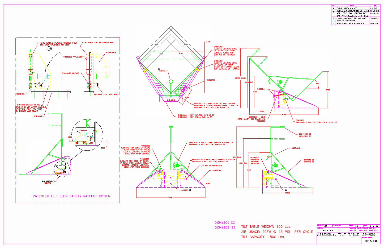
10.1 Mechanical Drawings
Mechanical assembly drawings for your system follow this page.
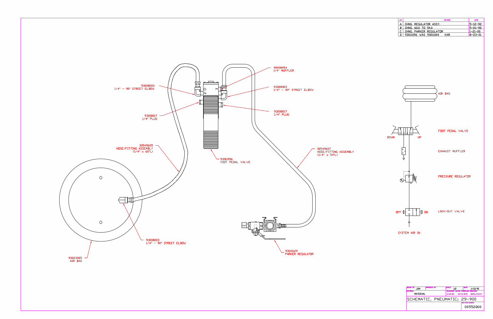
10.2 Controls Schematics
Electricalandfluidpowerschematicsforyoursystemfollowthispage.
93003053 CLEVIS
I 01310406
01310303 SPACER PLATE
==
0
0
91014007 3/ 4' RET. RING
I 94056009 <LOCATE TOP EDGE OF DECAL 1' DDIJN FROM TOP OF FRAME,
I LOCATE LEADING VERTICAL EDGE 1/2' FROM CORNER.)
94056006 <LOCATE TOP EDGE OF DECAL 1' DOIJN FROM ABOVE DECAL.
LOCATE LEADING VERTICAL EDGE 1/2' FROM CORNER,)
L PATENTED TILT LOCK SAFETY RATCHET �T�
94056010 <LOCATE LEADING EDGE OF DECAL 11.5' FROM CORNER, ALONG TDP SURFACE OF FLANGE)
94056010 <LOCATE LEADING EDGE OF DECAL 11' FROM START OF FLANGE, ALONG TOP SURFACE OF FLANGE)
94020006 - NUT, NYLOCKJ 3/8-16 ZP 94020008 - NUT, FULLJ 3/8-16 ZP
60.750 CHAX,>
00400100
D CHNG. 94056007 TD 006 AND 5-21-92DELETE 94056008
E ADDED RATCHET ASSEMBLY 11-21-95
00546801 - N,S,D, HERC-ALLOY 800 CHAIN 10'L
94035003 94031006 - PIN, COTTERJ 1/8 X 1-1/2 ZP
94005032 - BOLT, CARRJ 1/4-20 X 1-1/2 ZP 94020004 - NUT, NYLOCKJ 1/ 4-20 ZP
02.J12(lMX,)
94005001 - SCREIJ, HHCSJ 1/ 4-20 X 5/8 ZP
00547400 cs
00547401 ss
94020004 - NUT, NYLOCKJ 1/ 4-20 ZP ...... (1111.)
00398900 93004004 94006001 94020019
00400300 cs
00400301 ss
1/ 4 NPT AIR CONNECTION
00438500
00546800 cs
00546802 ss
J&.312
------- 51.188 --------1
TILT TABLE WEIGHT: 450 Lbs.
AIR USAGE: 2CFM @ 43 PSI PER CYCLE
TILT CAPACITY: 1500 Lbs. ASSEMBLY, TILT TABLE, 29-950

Append ix I A-1
We’re Here to Help
Conair has made the largest investment in customer support in the plastics industry. Our service experts are available to help with any problem you might have installing and oper-ating your equipment. Your Conair sales representative also can help analyze the nature of your problem, assuring that it did not result from misapplication or improper use.
How to Contact Customer Serv iceTo contact Customer Service personnel, call:
NOTE: Normal operating hours are 8:00 am - 5:00 pm EST. After hours emergencyservice is available at the same phone number.
From outside the United States, call: 814-437-6861You can commission Conair service personnel to provide on-site service by contacting the Customer Service Department. Standard rates include an on-site hourly rate, with a one-day minimum plus expenses.
Before You Cal l . . .If you do have a problem, please complete the following checklist before calling Conair:
U Make sure you have all model, control type from the serial tag, and parts list numbers for your particular equipment. Service personnel will need this information to assist you.
U Make sure power is supplied to the equipment.
U Make sure that all connectors and wires within and between control systems and related components have been installed correctly.
U Check the troubleshooting guide of this manual for a solution.
U Thoroughly examine the instruction manual(s) for associated equipment, especially controls. Each manual may have its own troubleshooting guide to help you.
Additional manuals and prints for your Conair equipment may be ordered through the Cus-tomer Service or Parts Depart-ment for a nominal fee. Most manuals can be down-loaded free of charge from the product section of the Conair website.www.conairgroup.com
0
A-2 I Append ix
Equipment GuaranteeConair guarantees the machinery and equipment on this order, for a period as defined in the quotation from date of shipment, against defects in material and workmanship under the normal use and service for which it was recommended (except for parts that are typi-cally replaced after normal usage, such as filters, liner plates, etc.). Conair’s guarantee is limited to replacing, at our option, the part or parts determined by us to be defective after examination. The customer assumes the cost of transportation of the part or parts to and from the factory.
Performance WarrantyConair warrants that this equipment will perform at or above the ratings stated in specific quotations covering the equipment or as detailed in engineering specifications, provided the equipment is applied, installed, operated, and maintained in the recommended manner as outlined in our quotation or specifications.
Should performance not meet warranted levels, Conair at its discretion will exercise one of the following options:
• Inspect the equipment and perform alterations or adjustments to satisfy performanceclaims. (Charges for such inspections and corrections will be waived unless failureto meet warranty is due to misapplication, improper installation, poor maintenancepractices, or improper operation.)
• Replace the original equipment with other Conair equipment that will meet originalperformance claims at no extra cost to the customer.
• Refund the invoiced cost to the customer. Credit is subject to prior notice by the cus-tomer at which time a Return Goods Authorization Number (RGA) will be issued byConair’s Service Department. Returned equipment must be well crated and in properoperating condition, including all parts. Returns must be prepaid.
Purchaser must notify Conair in writing of any claim and provide a customer receipt and other evidence that a claim is being made.
Warranty L imitat ionsExcept for the Equipment Guarantee and Performance Warranty stated above, Conair disclaims all other warranties with respect to the equipment, express or implied, arising by operation of law, course of dealing, usage of trade or otherwise, including but not limited to the implied warranties of merchantability and fitness for a particular purpose.