
Gautam Buddha · PDF fileGreater Noida – 201 312 . Website : . BID FORM. FOR THE SUPPLY...
33
TENDER BID : ADVANCE POWER ELECTRONICS & DRIVE LAB. Page 1 Gautam Buddha University (Established by the Uttar Pradesh Gautam Buddha University Act 2002 UP Act No. 9 of 2002, passed by the Uttar Pradesh Legislature) Greater Noida – 201 312 Website : www.gbu.ac.in BID FORM FOR THE SUPPLY / INSTALLATION OF LABORATORY EQUIPMENTS FOR ADVANCE POWER ELECT. & DRIVE LAB OF SCHOOL OF ENGINEERING
-
Upload
truongkhue -
Category
Documents
-
view
218 -
download
1
Transcript of Gautam Buddha · PDF fileGreater Noida – 201 312 . Website : . BID FORM. FOR THE SUPPLY...
TENDER BID : ADVANCE POWER ELECTRONICS & DRIVE LAB. Page 1
Gautam Buddha University (Established by the Uttar Pradesh Gautam Buddha University Act 2002
UP Act No. 9 of 2002, passed by the Uttar Pradesh Legislature)
Greater Noida – 201 312 Website : www.gbu.ac.in
BID FORM
FOR THE SUPPLY / INSTALLATION OF LABORATORY EQUIPMENTS FOR ADVANCE POWER ELECT. & DRIVE LAB
OF
SCHOOL OF ENGINEERING

Gautam Buddha University
(Established by the Uttar Pradesh Gautam Buddha University Act 2002 UP Act No. 9 of 2002, passed by the Uttar Pradesh Legislature)
Greater Noida – 201 312
SCHOOL OF ENGINEERING
Tender SUPPLY/INSTALLATION OF LABORATORY EQUIPMENTS OF ADVANCE POWER ELECTRONICS & DRIVE
Opening Date of Bid 08th July 2014
Closing Date & Time of Bid 28th July 2014 upto 3.00 p.m.
Last date & Time of Bid Submission
28th July 2014 upto 5.00 p.m.
Technical Bid Opening Date, Time & Place
30th July 2014 at 12.00 Noon
Venue : Conference Room of the Registrar Office, 1st Floor, Administrative Building, G.B.U., Gr. Noida. (Bidder/authorized representative of bidders may attend the bid opening proceedings on the above mentioned day and time).
Earnest Money Deposit Tender Fee
Rs.1,14,000.00 (Refundable) Rs.1050.00 (Non-refundable)
Completion Period Within 8 weeks from the date of Purchase Order issued
Bid System Two Tier : 1) Technical Bid 2) Financial Bid
Technical Bid Shall Contain
i. Technical specifications of each equipment quoted ii. All documents in support of commercial terms &
conditions and eligibility criteria. iii. Bidders Proforma iv. EMD in form of FDR only v. Tender Fee in form of demand drafts / pay orders.
Financial Bid The Financial Bid shall contain rate schedule only. The price shall be in words as well as in numeric numbers.

Gautam Buddha University
(Established by the Uttar Pradesh Gautam Buddha University Act 2002 UP Act No. 9 of 2002, passed by the Uttar Pradesh Legislature)
Greater Noida – 201 312
“TECHNICAL BID (BIDDER’S PROFORMA)”
(To be submitted in separate envelope)
Name of the Organization
Pl. mentioned whether a Government Company / Public Ltd. / Private Ltd. / Partnership / Proprietorship
Date of incorporation/registration (pl. enclose photocopy of cert.)
Specify the number of years in this line of activity by the company
PAN/TIN registration No. (pl. enclose photocopy of cert.)
Service Tax, Sales Tax/VAT registration No. (pl. enclose photocopy of cert.)
Provide the postal address, telephone & fax numbers, and email address of the nearest service center.
Are you the manufacturer / authorized dealer / distributor/ retailer for the product quoted (please attached relevant certificate):
Mention delivery period from the date of the placement of an official purchase order
Whether technical specification are attached with Technical Bid or not.
Deviations in specifications, if yes, please mention in separate sheet.
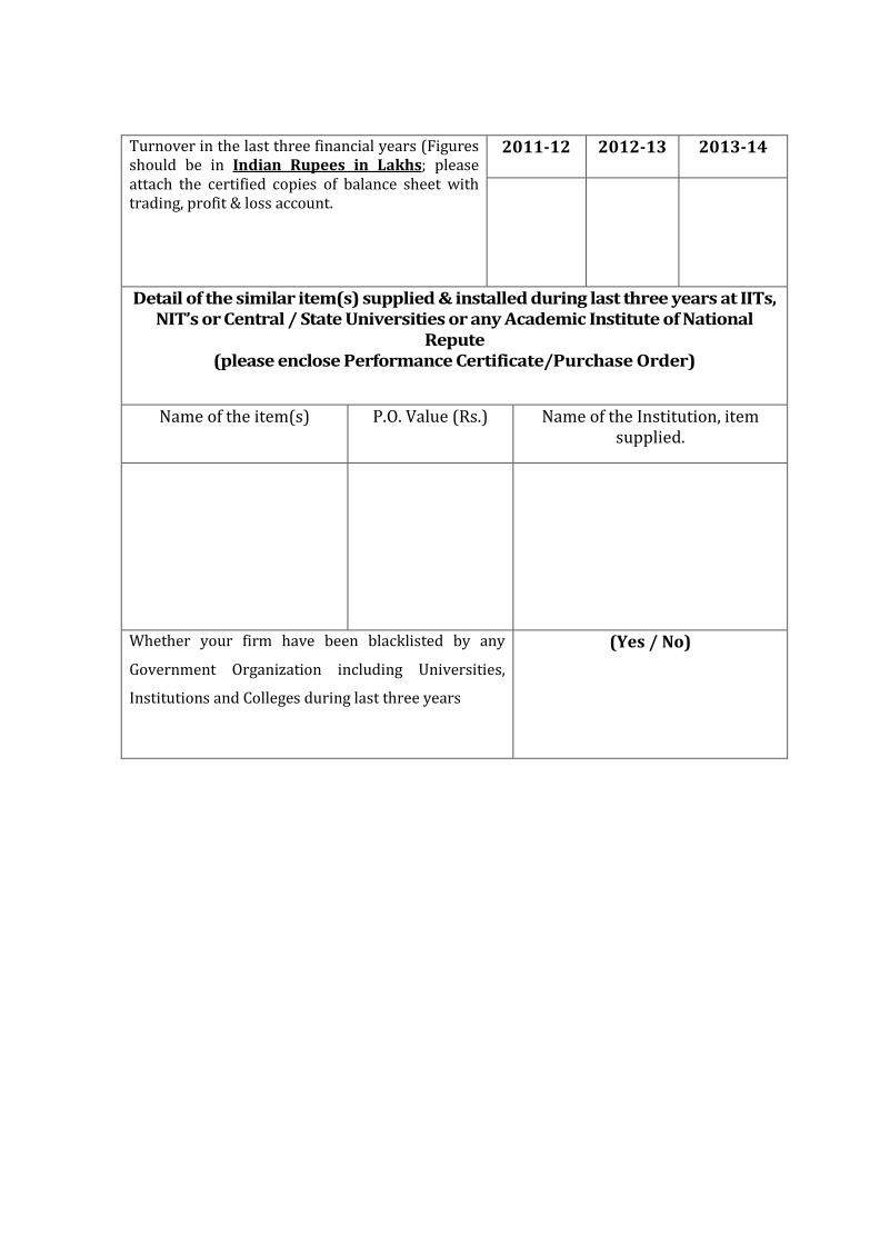
Turnover in the last three financial years (Figures should be in Indian Rupees in Lakhs; please attach the certified copies of balance sheet with trading, profit & loss account.
2011-12 2012-13
2013-14
Detail of the similar item(s) supplied & installed during last three years at IITs, NIT’s or Central / State Universities or any Academic Institute of National
Repute (please enclose Performance Certificate/Purchase Order)
Name of the item(s) P.O. Value (Rs.) Name of the Institution, item supplied.
Whether your firm have been blacklisted by any
Government Organization including Universities,
Institutions and Colleges during last three years
(Yes / No)

Gautam Buddha University
(Established by the Uttar Pradesh Gautam Buddha University Act 2002 UP Act No. 9 of 2002, passed by the Uttar Pradesh Legislature)
Greater Noida - 201 312
DECLARATION
I/We hereby declare that the information given in the technical bid by the undersigned is correct and fulfill all conditions as published in the tender document.
(SIGNATURE OF THE BIDDER) WITH SEAL
NAME: ……………………………………………………………….. ADDRESS : ……………………………………………………………
Tel./Mobile No. : ….......................................................................................

Gautam Buddha University
(Established by the Uttar Pradesh Gautam Buddha University Act 2002 UP Act No. 9 of 2002, passed by the Uttar Pradesh Legislature)
Greater Noida - 201 312
TECHNICAL SPECIFICATIONS OF ITEMS FOR ADVANCE POWER ELECT. & DRIVE LAB
S. No
ITEM TECHNICAL SPECIFICATIONS
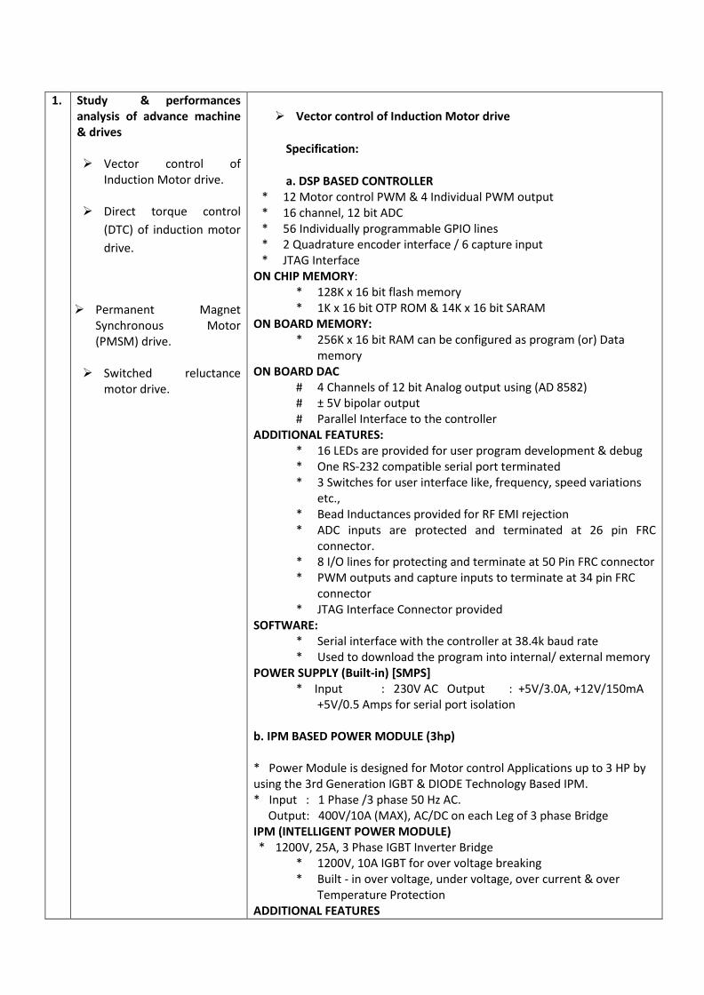
1.
Study & performances analysis of advance machine & drives
Vector control of
Induction Motor drive.
Direct torque control (DTC) of induction motor drive.
Permanent Magnet Synchronous Motor (PMSM) drive.
Switched reluctance
motor drive.
Vector control of Induction Motor drive
Specification:
a. DSP BASED CONTROLLER * 12 Motor control PWM & 4 Individual PWM output * 16 channel, 12 bit ADC * 56 Individually programmable GPIO lines * 2 Quadrature encoder interface / 6 capture input * JTAG Interface
ON CHIP MEMORY: * 128K x 16 bit flash memory * 1K x 16 bit OTP ROM & 14K x 16 bit SARAM
ON BOARD MEMORY: * 256K x 16 bit RAM can be configured as program (or) Data
memory ON BOARD DAC
# 4 Channels of 12 bit Analog output using (AD 8582) # ± 5V bipolar output # Parallel Interface to the controller
ADDITIONAL FEATURES: * 16 LEDs are provided for user program development & debug * One RS-232 compatible serial port terminated * 3 Switches for user interface like, frequency, speed variations
etc., * Bead Inductances provided for RF EMI rejection * ADC inputs are protected and terminated at 26 pin FRC
connector. * 8 I/O lines for protecting and terminate at 50 Pin FRC connector * PWM outputs and capture inputs to terminate at 34 pin FRC
connector * JTAG Interface Connector provided
SOFTWARE: * Serial interface with the controller at 38.4k baud rate * Used to download the program into internal/ external memory
POWER SUPPLY (Built-in) [SMPS] * Input : 230V AC Output : +5V/3.0A, +12V/150mA
+5V/0.5 Amps for serial port isolation b. IPM BASED POWER MODULE (3hp) * Power Module is designed for Motor control Applications up to 3 HP by using the 3rd Generation IGBT & DIODE Technology Based IPM. * Input : 1 Phase /3 phase 50 Hz AC. Output: 400V/10A (MAX), AC/DC on each Leg of 3 phase Bridge IPM (INTELLIGENT POWER MODULE) * 1200V, 25A, 3 Phase IGBT Inverter Bridge
* 1200V, 10A IGBT for over voltage breaking * Built - in over voltage, under voltage, over current & over
Temperature Protection ADDITIONAL FEATURES
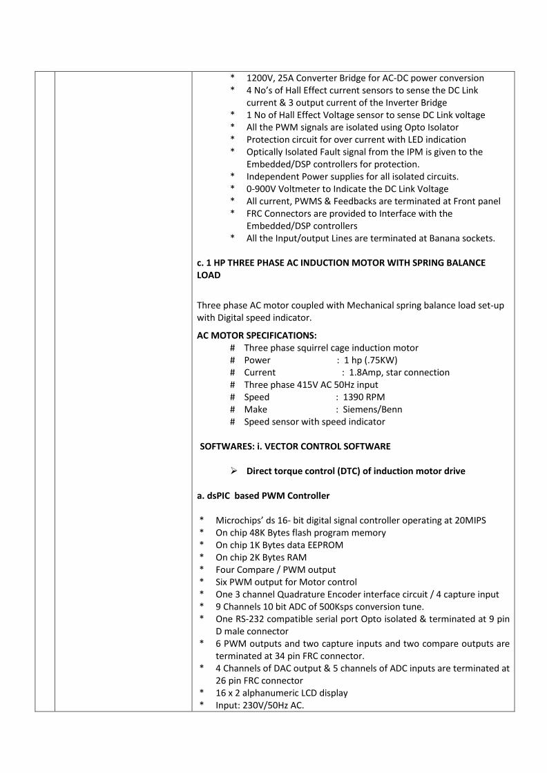
* 1200V, 25A Converter Bridge for AC-DC power conversion * 4 No’s of Hall Effect current sensors to sense the DC Link
current & 3 output current of the Inverter Bridge * 1 No of Hall Effect Voltage sensor to sense DC Link voltage * All the PWM signals are isolated using Opto Isolator * Protection circuit for over current with LED indication * Optically Isolated Fault signal from the IPM is given to the
Embedded/DSP controllers for protection. * Independent Power supplies for all isolated circuits. * 0-900V Voltmeter to Indicate the DC Link Voltage * All current, PWMS & Feedbacks are terminated at Front panel * FRC Connectors are provided to Interface with the
Embedded/DSP controllers * All the Input/output Lines are terminated at Banana sockets.
c. 1 HP THREE PHASE AC INDUCTION MOTOR WITH SPRING BALANCE LOAD
Three phase AC motor coupled with Mechanical spring balance load set-up with Digital speed indicator.
AC MOTOR SPECIFICATIONS: # Three phase squirrel cage induction motor # Power : 1 hp (.75KW) # Current : 1.8Amp, star connection # Three phase 415V AC 50Hz input # Speed : 1390 RPM # Make : Siemens/Benn # Speed sensor with speed indicator
SOFTWARES: i. VECTOR CONTROL SOFTWARE
Direct torque control (DTC) of induction motor drive a. dsPIC based PWM Controller * Microchips’ ds 16- bit digital signal controller operating at 20MIPS * On chip 48K Bytes flash program memory * On chip 1K Bytes data EEPROM * On chip 2K Bytes RAM * Four Compare / PWM output * Six PWM output for Motor control * One 3 channel Quadrature Encoder interface circuit / 4 capture input * 9 Channels 10 bit ADC of 500Ksps conversion tune. * One RS-232 compatible serial port Opto isolated & terminated at 9 pin
D male connector * 6 PWM outputs and two capture inputs and two compare outputs are
terminated at 34 pin FRC connector. * 4 Channels of DAC output & 5 channels of ADC inputs are terminated at
26 pin FRC connector * 16 x 2 alphanumeric LCD display * Input: 230V/50Hz AC.
* PIC Programmer b. IPM (INTELLIGENT POWER MODULE)
* 1200V, 25A, 3 Phase IGBT Inverter Bridge * 1200V, 10A IGBT for over voltage Breaking * Built - in over voltage, under voltage, over current & over
Temperature protection ADDITIONAL FEATURES * 1200V, 25A Converter Bridge for AC-DC power conversion * 4 Nos. of Hall Effect current sensors to sense the DC Link current & 3
output current of the Inverter Bridge * 1 No. of Hall Effect Voltage sensor to sense DC Link voltage * All the PWM signals are isolated using Opto Isolator * Protection circuit for over current with LED indication * Optically Isolated Fault signal from the IPM is given to the
Embedded/DSP controllers for protection. * Independent Power supplies for all isolated circuits. * 0-900V Voltmeter to Indicate the DC Link Voltage * All current, PWMS & Feedbacks are terminated at Front panel * FRC Connectors are provided to Interface with the Embedded/DSP
controllers * All the Input/ Output Lines are terminated at Banana sockets. c. 1 HP SINGLE PHASE AC MOTOR – SPRING BALANCE LOAD SETUP WITH QEP SENSOR This set up should be consist of one number of (1) single phase ac motor (2) mechanical spring balance load set-up
AC MOTOR SPECIFICATION:
# Power : 1hp # Single phase permanent # Capacitor type # 230VAC, 50 Hz input # Speed : 1400 rpm
d. 3 φ ISOLATION TRANSFORMER 1 KVA * Input: 0 – 230 V AC (3 Phase) * Output: 110 – 0 – 110 V AC (3-Phase)
Permanent Magnet Synchronous Motor (PMSM) drive
a. DSP BASED CONTROLLER The digital signal controllers (DSCs) generation, are highly integrated, high-performance solutions for demanding control applications. On-Chip Features: * Up to 150 MHz (6.67-ns Cycle Time) * 16 x 16 and 32 x 32 MAC Operations * Up to 18 PWM Outputs
* Up to 6 HRPWM Outputs with 150 ps MEP Resolution * Up to 6 Event Capture Inputs * Up to 2 Quadrature Encoder Interfaces Memory: * 512K bytes on-chip Flash Memory * 68K bytes on-chip RAM * 256k bytes off-chip SRAM memory (External) On-chip ADC: * No of ADC input : 16 Channels * Resolution : 12 bit * Conversion rate : 80ns (max) On-Board DAC: * No of DAC output : 4 Channels * Resolution : 12 bit * Settling time : 8.5 micro sec (max) * Analog output range: +5V (max) * High speed serial interface, SPI compatible. On-Board JTAG Emulator: * Debug features: Emulation connect/Disconnect, Read/Write memory, Read registers, Load program, Run, Halt, Step, Software & Hardware Breakpoint support, Real- Time Mode. * Support for USB Full Speed (12 M bits/s) Additional Features * 16 user definable LED's * On board RS-232 connector with line driver * 3 Switches are provided for user interface link frequency speed variations etc., * ADC Inputs are protected and terminated at 26 pin FRC Connector * PWM Outputs and capture inputs are terminated at 34 pin FRC Connector * I/O lines are protected and terminated at 50 pin FRC Connector * JTAG interface connector provided b. IPM BASED POWER MODULE (3hp) * Power Module is designed for Motor control Applications up to 3 HP by using the 3rd Generation IGBT & DIODE Technology Based IPM. * Input : 1 Phase /3 phase 50 Hz AC. Output: 400V/10A (MAX), AC/DC on each Leg of 3 phase Bridge
IPM (INTELLIGENT POWER MODULE) • 1200V, 25A, 3 Phase IGBT Inverter Bridge • 1200V, 10A IGBT for over voltage breaking
Built - in over voltage, under voltage, over current & over Temperature Protection ADDITIONAL FEATURES
• 1200V, 25A Converter Bridge for AC-DC power conversion • 4 No’s of Hall Effect current sensors to sense the DC Link current & 3
output current of the Inverter Bridge • 1 No of Hall Effect Voltage sensor to sense DC Link voltage • All the PWM signals are isolated using Opto Isolator • Protection circuit for over current with LED indication • Optically Isolated Fault signal from the IPM is given to the
Embedded/DSP controllers for protection. • Independent Power supplies for all isolated circuits. • 0-900V Voltmeter to Indicate the DC Link Voltage • All current, PWMS & Feedbacks are terminated at Front panel • FRC Connectors are provided to Interface with the Embedded/DSP
controllers • All the Input/output Lines are terminated at Banana sockets. c. 1 HP PMSM MOTOR – SPRING BALANCE LOAD SET UP WITH HALL SENSOR Speed - 4600rpm Rated Voltage - 220 VAC Rated current - 3.69 A Rated Torque - 2.2 N-M Power - 1.1 HP Position Feedback - (Encoder 2000 PPR & Index Pulse) & 3Nos.of hall Sensors placed with 120 Electrical degrees apart Rotor pole - 4 Poles Phase - 3φ Back EMF - Sinusoidal
Make - Motor Power Switched reluctance motor (SRM) drive using DSP
a. DSP BASED CONTROLLER On-Chip Features: * Up to 150 MHz (6.67-ns Cycle Time) * 16 x 16 and 32 x 32 MAC Operations * Up to 18 PWM Outputs * Up to 6 HRPWM Outputs with 150 ps MEP Resolution * Up to 6 Event Capture Inputs * Up to 2 Quadrature Encoder Interfaces Memory: * 512K bytes on-chip Flash Memory * 68K bytes on-chip RAM * 256k bytes off-chip SRAM memory (External) On-chip ADC: * No of ADC input : 16 Channels * Resolution : 12 bit * Conversion rate : 80ns (max) On-Board DAC: * No of DAC output : 4 Channels * Resolution : 12 bit
* Settling time : 8.5 micro sec (max) * Analog output range: +5V (max) * High speed serial interface, SPI compatible. On-Board JTAG Emulator: * Debug features: Emulation connect/Disconnect, Read/Write memory, Read registers, Load program, Run, Halt, Step, Software & Hardware Breakpoint support, Real-Time Mode. * Support for USB Full Speed (12 M bits/s) Additional Features * 16 user definable LED's * On board RS-232 connector with line driver * 3 Switches are provided for user interface link frequency speed
variations etc., * ADC Inputs are protected and terminated at 26 pin FRC Connector * PWM Outputs and capture inputs are terminated at 34 pin FRC
Connector * I/O lines are protected and terminated at 50 pin FRC Connector * JTAG interface connector provided b. SRM POWER MODULE ∗ This power module should be design for 4- Phase Switched reluctance
Motor speed control application up to 1- hp ratings by using the latest SR-IPM. Any external PWM controller (like DSP, Micro controller, FPGA controller) can be interfaced with this power module for SR-Motor open / closed loop speed control application.
* Two number of latest SR-IPM (or) four number of IGBT-power module with heat sink and snubber Circuit-forms Split-DC link power circuit for SR motor control.
* High-speed opto provided for all IGBT PWM isolation. * One No of single phase diode bridge converter with capacitor provided
for input AC-DC conversion for power circuit. * One No of split capacitor for SR-Power circuit. * One number of analog voltmeter provided for DC rail voltage
measurement. * Four number of hall-effect current sensor with signal conditioning circuit
provided for output and DC input current measurement. * One No. of SR-position-sensor signal conditioning circuit provided. * One number of position signal to speed sensor circuit provided for closed
loop operation. * One number of over-current trip circuit with indicator & reset switch
provided for protection. * Two No. of LED provided in the front panel for SR position status
indication. * Two number of special connector provided in the front panel for SR-
motor power input and position feed backs. * Test points provided in the front panel for PWM and current waveform
measurement. * Two No. of banana connector provided for power circuit input with MCB. * One No. of 34 pin connector & 24 pin connector provided in the front
panel for PWM input and feedback signals to controller. * 230v AC input with +/_15v DC supply for control circuit input. * One number of illuminated rocker switch provided for power on/off with
fuse protection. * All are mounted in the nice cabinet with sticker front panel. With
detailed manual. * Specification: # Input : 230v AC @ 50hz # Output : suitable for four phase SR-motor # Power : 0.75kw /1 hp. * Optional load facility: * One number of IGBT based single quadrant chopper power circuit
provided for variable DC voltage to eddy-dynamometer for SR motor loading-purpose.
c. 1 HP SR MOTOR - SPRING BALANCE LOAD SET UP WITH SENSOR * Input Voltage : 380V pulsed DC * Type : Switched Reluctance Motor * Power : 1Hp * * Max. Speed : No load / Full Load 4500 / 2800rpm / 3A * Optical Type Position sensor * Spring balance loading arrangement
2. Study & analysis of Advance Converter
• 3-Phase Cyclo-
converter
3-Phase Cyclo-converter * This module requires with 3-phase half wave - step down Cyclo- converter. * It should be consists of 18 Synchronized firing pulses, 18 SCRs, Relevant power supply and circuitry for frequency divisions. Main Circuit : * 18 Nos. SCR with RC snubber protection is provided for 3Ph Cyclo-converter power circuit (each phase consist of 6 SCRs) Rated at 1200 V @ 25 Amps. * 3 Nos. center tapped inductor (0%. 50%, 100%) is provided for power circuit. * 18 Nos. isolated gate pulses for SCR power circuit. * One potentiometer is provided to vary the frequency. * One potentiometer is provided to vary the output voltage. * MCB protection. * Housed in sleek screen printed cabinet. * Provision for V/F control Power Supply : * Input 440V ± 10%, 50Hz three phase AC supply. * ± 15V DC, 9V, 9V,9V AC(3N) for the firing circuits. Output Ranges : * Frequency Variation : 1 Hz to 1/3 rd of supply frequency (Approx : 1 Hz to 16Hz) * Voltage Variation: 0 to 90% of supply voltage.
• 3-Phase Inverter
Load specifications: 3- Phase Loading Rheostat:
∗ 1KW rating ∗ 3- phase input ∗ Different selector switch provided for current selection ∗ Fuse provided for input protection ∗ All are mounted on a moveable cabinet ∗ Banana connector provided for load input
3- phase Inductive load:
∗ 120mH, 4Amps rating for each phase ∗ 3- Phase Inductive Load ∗ With 6 Nos. of Tappings Iron Core type ∗ Banana connector for all inputs
3- Phase PWM Inverter with induction motor load SPEED CONTROL OF THREE PHASE INDUCTION MOTOR CONTROLLER USING SCR INVERTER * This trainer should be designed to drive the 3-phase AC induction motor using SCR based V/F controller. (Open / closed loop). * SCR based three phase converter and inverter forms V / F controller. * Variable voltage achieved by controlling the firing angle of SCR converter. Variable frequency achieved by controlling the firing pulse frequency of SCR Mc-Murray inverter. SCR Converter and firing circuit: * Op-amp Based linear firing circuit gives [0°-180°d] firing angle variation. * One no. potentiometer used to vary the firing angle adjustment. * All six pulses isolated by pulse transformer and terminated in the front panel. * Six No’s TYN1225 SCR forms single phase fully controlled converter with LC filter gives 600V DC to SCR inverter. ∗ MCB and fuse (DC side ) provided for over current protection. ∗ DC voltmeter provided for DC rail voltage measurement. SCR MC-MURRAY INVERTER AND FIRING CIRCUIT * IC Based three phase firing circuit with variable frequency (10 - 50 Hz). * [0 - 5V] DC adjust the firing angle frequency. Six No’s Firing pulse with pulse transformer isolation terminated in the front panel. * Six No’s TYN612 SCR and six No’s diode forms power circuit. six No’s capacitor and three No’s center tapped inductor for commutation.
• DC-DC Buck boost Converter trainer
* Separate control circuits for adjusting V / F ratio. Provision to control the V / F ratio in external [0 - 50V] DC (closed loop). * Input : 440V AC 3 phase * Output : [0 - 415V] variable AC and [10-50 Hz] variable frequency * Current: 5Amp. Load specifications: 1 HP THREE PHASE AC MOTOR This set up consists of one number of AC MOTOR SPECIFICATIONS: # Three phase squirrel cage induction motor. # Power : 1hp (0.75kw) # Current : 1.8amp, star connection # Three phase 415vac 50hz input # Speed : 1390 rpm DC- DC Buck Boost Converter trainer
This set-up should be designed to study the working principle of buck-boost dc-dc converter. It consists of 1. Buck-boost converter PWM control circuit. 2. Buck-boost converter power circuit. 3. 0-30v dc power supply for power converter input. 1. BUCK-BOOST CONVERTER PWM CONTROL CIRCUIT: * TL494 based PWM controller for converter PWM generation. * One number potentiometer provided for set voltage adjustment. * One number of dpdt switch provided for open loop/closed loop
selection. * One number of dpdt switch provided for buck-boost mode selection. * One number of pulse socket provided for feedback voltage-interface * One number of pulse socket provided for PWM output- interface. * Varies test points provided for wave form measurement. * Circuit diagram printed in the front panel PCB. * One number of power on/off switch with indicator. 2. BUCK-BOOST CONVERTER POWER CIRCUIT: * One number of IRF250 power MOSFET provided for power device. * High speed opto provided for MOSFET PWM isolation. * IR2110 IC provided for MOSFET PWM driver. * One number of high-frequency inductor and capacitor and diode
provided for power circuit. * One number of output voltage divider circuit provided for feed -back
voltage. * One number of pulse socket provided for feedback voltage-output. * One number of pulse socket provided for PWM input. * One number of fixed R-provided for load resistor. * Low value (0.2e) resistor provided in varies sections of power circuits for
current wave-form measurement.
* Banana connectors provided for power circuit input and outputs. * Fuse provided for output side for over load protections. Specifications: # Input : 0-15vdc # Output: 0-30v dc (boost) @ 0.5A 5VDC@1Amp (buck). 3. 0-30V VARIABLE DC SUPPLY FOR POWER CIRCUIT INPUT: * Variable dc power supply. * 0-30 V dc output @ 2amp capacity. * One number of potentiometer provided for output voltage variation. * One number of potentiometer provided for output current variation. * One number of led display provided for o/p voltage / current
measurement. ∗ Built in over-current limit facility.
3. Study & analysis of STATCOM
• STATCOM
FACTS / STATCOM THREE PHASE FACTS CONTROLLER Supply installation , testing and commissioning of FACTS CONTROLLER including complete accessories consisting of following modules and components i) Transmission Line Simulator Model – suitable L & C (400V/4A with different toppings) for simulating three phase transmission line. Input voltage – 3 phase, 400V, 1A/phase, Three phase 2KVA, 415V auto transformer with control switches / circuit breakers ii) Three phase Generator setup – a) 3 Phase Alternator DC motor drive setup 3phase/2KVA/1500rpm/salient pole type/alternator /coupled with 2hp /220V DC shunt motor with suitable drive from 1 phase or 3 phase AC input supply with suitable speed control + sensor and digital speed indicator b) 3 Phase, 2KVA induction generator provided with accessories to work in parallel with the alternator using the shunt motor as the prime motor. c) Digital controller with IGBT based DC voltage controller for DC motor armature voltage variation 0-200V DC/10A & alternator field voltage variation with necessary instruments/meters/ indicators
i. IGBT BASED POWER MODULE
(VOLTAGE SOURCE CONVERTER (VSC) - IGBT based Three Phase Inverter for SATCOM, UPFC, SSSC applications.) * 600V, 20A 3 Phase IGBT based inverter bridge - 2Nos. * 1200v, 25A Uncontrolled rectifier with capacitors for converting AC
input to DC link voltage. * Outputs of IGBTs in DIPM terminated at Banana sockets * Hall sensors provided to sense DC link voltage, DC link current and the
DIPM output currents. * 6 High side and 6 low side High speed optos to isolate gating signals to
DIPM
* Independent on board power supplies to all channels * Optically isolated fault output from DIPM * Built in control power supply * Test points on the front panel to monitor/measure the voltages and
currents as well as control power supply * DC voltmeter to measure the DC link voltage * Protection for short circuit, over current, earth fault, over voltage,
under voltage and over temperature provided * Input: 1 Phase 230V/300vdc * Output AC: variable frequency and voltage * FRC connectors to interface with DIPM. * One number of 2 KVA auto transformers for VSC input voltage.
ii. DSP CONTROLLER WITH VISSIM SOFTWARE
DSP BASED CONTROLLER 32- bit DSP Processor operating at 150MIPS ON CHIP FEATURES:
* 12 Motor control PWM & 4 Individual PWM output * 16 channel, 12 bit ADC * 56 Individually programmable GPIO lines * 2 Quadrature encoder interface / 6 capture input * JTAG Interface
ON BOARD MEMORY: * 256K x 16 bit RAM can be configured as program (or) Data
memory
ON BOARD DAC # 4 Channels of 12 bit Analog output using (AD 8582) # ± 5v bipolar output. # Parallel Interface to the controller.
ADDITIONAL FEATURES: * 16 LEDs are provided for user program development & debug * One RS232 compatible serial port terminated * 3 Switches are provided for user interface like, frequency,
speed variations etc., * Bead Inductances provided for RF EMI rejection * ADC inputs are protected and terminated at 26 Pin FRC
connector. * 8 I/O lines are protected and terminated at 50 Pin FRC
connector * PWM outputs and capture inputs are terminated at 34 pin FRC
connector * JTAG Interface Connector provided
POWER SUPPLY (Built-in) [SMPS]:
* Input : 230V AC * Output : +5V/3.0A, +12V/150mA +5V/0.5 Amps for serial
port isolation iii. VISSIM Sofware package for DSP Programming iv. TI Emulator (USB JTAG Emulator) Features: Supports USB 1.x and USB 2.0 (full speed)
∗ Operates off PC/Laptop USB port ∗ Advanced emulation controller provides high performance
and fast download speeds ∗ Supports devices with +3.3V and +5V JTAG levels ∗ USB bus powered, no power supply required ∗ Compatible with +3.3V or +5V processors ∗ One LED provides operational status
v. TI Software Tools DSPS CODE COMPOSER STUDIO IDE
* Works with windows 2000/XP * Integrated development environment (code composer) with
editor, debugger, project manager, profile and probe points
* C/C++ compiler, Assembler and linker (code generation tools) * Instruction set simulator * Real time software kernel (DSP/BIOS) * Real time data exchange between host and target * Real time analysis and data visualization tools * Code composer integrates all host and target tools in a unified environment to supply DSP system configuration and application design.
REAL TIME OPERATING SYSTEM [DSP /BIOS REAL TIME KERNEL]
* Provides common run time objects * DSP/BIOS real time Kernel provides low latency threading and I/O
programs on the DSP target hardware. * It is biased as a library of re locatable reentrant object modules ∗ The DSP/BIOS run time system's small size makes it practical to embedded directly into a DSP's on-chip boot ROM
vi. TRANSFORMERS WITH LC FILTER.
* One No. of Three Phase 1 KVA transformers act as Shunt Transformer with capacitor filter provided for STATCOM applications
* One No. of Three Phase 1 KVA transformers act as Series

Transformer with capacitor filter provided for SSSC applications vii. DIGITAL INSTRUMENTS & CONTROL PANEL
Digital meters to indicate sending end, receiving end parameters. Sending end/Receiving end parameters:- Voltage, current, power factor phase angle active power & reactive power waveform Energy- Kwh, KVARh.
Load & specifications: Variable Three phase RLC Load with controls - 3KVA
4.
Study of advance PWM Technique.
dsPIC 30F4011 based PWM Controller for Sinusoidal PWM Generation * Microchips’ dsPIC30F4011 16 bit digital signal controller operating at
20MIPS * Onchip48K Bytes flash program memory * On chip 1K Bytes data EEPROM * On chip 2K Bytes RAM * Four Compare / PWM output * Six PWM output for Motor control * One 3 channel Quadrature Encoder interface circuit / 4 capture input * 9 Channels 10 bit ADC of 500Ksps conversion tune. * One RS232 Compatible serial port Opto isolated & terminated at 9 pin D male connector * 6 PWM outputs and two capture inputs and two compare outputs are terminated at 34 pin FRC connector. * 4 Channels of DAC output & 5 channels of ADC inputs are terminated at 26 pin FRC connector * 16 x 2 alphanumeric LCD display * Input: 230V/50Hz AC. * PIC Programmer
5.
Study and training on power supplies- UPS and SMPS.
UPS TRAINER MODULE Consists of the following three modules namely , a.Main circuit module b.Battery charger module c.Battery module
A. MAIN CIRCUIT MODULE:
∗ MOSFET based push-pull inverter ∗ PWM controller using SG3525 to generate gating signals to the MOSFET ∗ 24/230V step up transformer to set-up inverter output voltage ∗ Battery monitoring circuit monitoring the battery voltage levels and
protect the deep discharging effect of battery ∗ A temperature sensing circuit to produce signals during over
temperature conditions to protect the switching devices
∗ A buzzer which produces a warning alarm during fault conditions ∗ SPDT switches to simulate fault conditions ∗ LED indication for various fault conditions mains on and inverter on
conditions ∗ A SPDT switch for selecting ON/OFF line working of UPS ∗ Banana connectors for AC input , AC output and battery input
connections B. BATTERY CHARGING MODULE ∗ 230/27V step down transformer ∗ Bridge rectifier ∗ Two SCRs are provided to control the battery charging ∗ A current set potentiometer is provided for setting desired charging
current ∗ Banana connectors are provided for AC input and also for battery
connections ∗ LEDs are provided to indicate over current, trickle charge, charger on
conditions. C. BATTERY MODULE ∗ Fuse protection provided ∗ 24v DC battery ∗ output voltage 230V 10% AC square wave ∗ output frequency 50Hz, 5% ∗ output power 0.5A Capacity SMPS POWER MODULE:
Switch mode power supplies (SMPS) become an integral part of
computers, Electronic equipments, TV’s and etc,. It is extensively used in latest IBM compatible computers, which forces the engineers to understand it thoroughly. In order to understand the SMPS technically, Vi Microsystems has introduced a single and multiple output SMPS trainer module. The detailed specifications of this trainer is as follows:
This module consists of three separate sections, ∗ Input power module ∗ DC-DC converter module ∗ Electronic module A. INPUT POWER MODULE Input power module is provided with one Auto transformer and a
230V/24 volt transformer to provide 0-24Volt AC output to the DC-DC converter module.
∗ One single phase auto transformer provided to vary the input voltage and applied to the transformer input, so that the transformer output will vary from 0-24Volt
∗ One no. of 230/ 24V, 3Amp transformer provided for output isolation ∗ One no. of 0-30V Ac voltmeter provided to indicate output voltage ∗ One illuminated rocker switch is provided to on/off input power
∗ One fuse is provided to avoid over current ∗ One pilot lamp provided to indicate power on/off ∗ All outputs, auto transformer, voltmeter mounted on a screen printed
PCB with nice cabinet ∗ Inputs 0-230V AC ∗ Output 0-24V AC/ 3Ampa variable, isolated B. DC-DC CONVERTER MODULE ∗ TL494 based PWM controller IC operated at 63KHz (approx) ∗ IRF540/840 used as a power switch with suitable heat sinks ∗ Provision for selection of single output or multi output by means of SPDT
switch ∗ Pulse is isolated by means of opto coupler ∗ Output is filtered by LC filter ∗ All input, outputs are terminated by banana sockets ∗ Necessary test points are provided on the board ∗ Various fault analysis switches provided to study SMPS controller ∗ One potentiometer is provided to vary the frequency of PWM (External
mode of operation) ∗ One potentiometer is provided to vary the reference voltage of PWM
controller IC ∗ Input: 0-24V AC/ 3Amps ∗ Output (Multiple): +5V/1Amp, +12V, -12V ∗ Output (Single ): +5V/1amp ; C. ELECTRONIC LOAD: A PWM generator, a static switch & a fixed load resistor form the
electronics load. By varying the PWM width, the load current is varied. ∗ It consists of one no. of 20-0-20V DC voltmeter to measure SMPS
output voltages ∗ One Ammeter 0-3Amps provided to indicate load current ∗ One multi turn potentiometer is provided to vary the PWM width which
in term vary the load current ∗ Input Voltage: +5V & 12Volt ∗ Maximum load current: 1Amps for 5 volt ∗ Input banana connectors and all meters are mounted on a screen
printed PCB with nice cabinet
6. Study & performance evaluation of different FPGA based controller
FPGA BASED DC MOTOR CONTROLLER
SPECIFICATIONS: SPARTAN 6 FPGA Development Board ∗ 24,051 logic cells ∗ 229kB Distributed RAM ∗ 936Kb Block RAM ∗ 38 no’s of DSP48A1 Slices
∗ 2 Clock management Tiles ∗ 2 Memory controller blocks ∗ 34 Pin Header # 16 PWM output # 8 Capture Inputs ∗ 100MHz variable clock ∗ 26 Pin Header ADC # 8 channel 2 msps ADC # 12 bit resolution # Input range: 0 to 5 V ∗ 5 Pin phoenix connector # 4 channel 125KHz DAC # 12 bit resolution # Output range: 0 to 5 V ∗ Interfaces # JTAG programming & configuration port # Isolated RS232 port (USB to serial) # One RS232/SPI port ∗ Inputs and Outputs # 8 User LEDs # 8 Position user DIP switch # 4 User push button switches # Reset push button switch # 2 User limit switch ∗ Display # 20x4 alpha numeric LCD display ∗ Expansion # 2 no of 20 pin box type header is provided with 36 no of 3.3V compatible
I/O lines.
b)IPM (INTELLIGENT POWER MODULE)
1200V, 25A, 3 Phase IGBT Inverter Bridge 1200V, 10A IGBT for over voltage breaking Built - in over voltage, under voltage, over current & over Temperature
Protection ADDITIONAL FEATURES
∗ 1200V, 25A Converter Bridge for AC-DC power conversion ∗ 4 No’s of Hall Effect current sensors to sense the DC Link current &
3 output current of the Inverter Bridge ∗ 1 No of Hall Effect Voltage sensor to sense DC Link voltage ∗ All the PWM signals are isolated using Opto Isolator ∗ Protection circuit for over current with LED indication ∗ Optically Isolated Fault signal from the IPM is given to the
Embedded/DSP controllers for protection. ∗ Independent Power supplies for all isolated circuits. ∗ 0-900V Voltmeter to Indicate the DC Link Voltage ∗ All current, PWMS & Feedbacks are terminated at Front panel ∗ FRC Connectors are provided to Interface with the Embedded/DSP
controllers ∗ All the Input/output Lines are terminated at Banana sockets.
c. 1 HP PMSM MOTOR – SPRING BALANCE LOAD SET UP WITH HALL SENSOR Speed - 1500rpm Rated Voltage - 220 VDC Rated current - 3.69 A approx Rated Torque - 2.2 N-M
Power - 1 HP
7.
Study & Training on PLC based Automation for motor control.
PLC based Automation for motor control
Specifications: a. Three phase SCR power circuit
∗ Three no of SCRs mounted on suitable heat sinks and placed inside a
nicely designed cabinet ∗ Three Diodes each rated at 1200V @ 25A ∗ Each diode is provided with RC Snubber ∗ The diodes are mounted on a suitable heat sinks ∗ Facilities are provided for switching ON/OFF, the AC supply to the
converter circuit with fuse and miniature circuit Breaker protection ∗ Front panel provisions ∗ Required SCR and diode points are terminated at sockets for easy wiring
by patch chords for form half or full bridge converter and AC regulator ∗ Various circuit configurations like half and fully controlled bridge can be
wired by Interconnecting the devices using patch cords ∗ Housed in a sleek cabinet ∗ Pulse amplifier and isolator circuit, AC Synchronizing circuit is provided. b. Chopper/Inverter PWM controller: PWM signals for IGBT / MOSFET chopper / Inverter Fed Ac / Dc drive with
Open loop & Closed loop. Features:
* One number of Digital Controller (dsPic30f4011) provided for PWM Generation. Microchip’s dsPIC30F4011 16 bit digital signal controller operating at 33 nS ,On chip-motor control peripherals 6 motor control PWM with programmable dead band , quadrature Encoder interface
∗ Memory (On-chip) # 48K Flash program memories # 2K RAM for data memory # 1K EEPROM memory ∗ Additional features # On chip isolated serial port # ADC input lines are protected and terminated
# Bead inductances are provided at VCC & GND for EMI rejection * Five Number of Touch Key Provided for PWM Mode Selection * One number of LCD provided to indicate Motor set speed , actual speed,
chopper mode etc * One Number of toggle switch provided for PWM Enable / Disable
selection * +5V 1Amp isolated dc supply provided for control circuits. * All are mounted in a nice powder coated cabinet with stickered front
panel mimic diagram indication * 230VAC input, one number of power On/Off switch with indication * One number of 15 pin connector provided for PWM output to external
power module * One number of 9 pin connector provided for Speed sensor Interface * 7 Numbers of test points provided in the front panel for waveform
measurements. ACCESSORIES: (1) THREE PHASE LOADING RHEOSTA ∗1KW rating *Three phase input ∗Different selector switch provided for current selection ∗Fuse provided for input protection ∗All are mounted on a moveable cabinet ∗Banana connector provided for load input
(2) THREE PHASE INDUCTIVE LOAD ∗ 5Amp capacity ∗ Variable type * Three phase input ∗ Fuse provided for input protection ∗ Banana connector provided for input.
8. Wind / solar based hybrid system with 1-pahse AC source
Wind / solar based hybrid system with 1-phase AC source This Module will be used to study the Hybrid Power Generation and study
about each Modules involved like Solar cell, Wind Generator, Charger Circuit, Inverter Circuit and Controller.
Details as Below: a. Solar Cell:- ∗ 100W Solar Cell ∗ Poly Crystalline ∗ Peak volt at no load 21V ∗ Peak Current 5A ∗ Potentiometer for IV curve b. Solar Cell stand with Halogen lamp:- ∗ Tiltable Stand ∗ 1 axis movement ∗ 1000 watts Halogen Lamp with intensity control ∗ Fixing Arrangement c. Charge Controller:- ∗ MOSFET based charger ∗ With MPPT Control
∗ Maximum input 30V / 5A ∗ Output 12V / 10 Amps d. Wind Generator Module:- ∗ 100W PMDC motor type generator ∗ Fixed in mechanical fixture with Grill Protection ∗ Indoor Purpose e. Blower Assembly for simulated Wind Source ∗ Fixed in a mechanical frame ∗ Safety grill arrangement to avoid physical damage to the student ∗ Wind force can variable through relay contacts f. Charger Controller for the Wind Generator ∗ MOSFET Based Charger ∗ With MPPT Algorithm g. Inverter:- ∗ MOSFET Based Inverter ∗ Double Stage Inverter ∗ Input Voltage 12V Battery ∗ Output Voltage 23OV AC ∗ Output Power 650 Watts ∗ Quasi Sine Wave Output Experiments: ∗ Study the Working Principle and Characteristics of Inverter ∗ Study the Efficiency h. Output Panel:- ∗ Voltmeter for Output Voltage ∗ Ammeter for Output Current ∗ Voltmeter for Battery Voltage ∗ Ammeter for Battery Current ∗ Voltmeter for Solar output Voltage ∗ Ammeter for Solar Cell Current ∗ Voltmeter for Wind Generator Output Voltage ∗ Ammeter for Wind Generator Output Current i. Data Acquisition for required Input and Output j. Lamp Load Setup – Lamp Load
9.
Digital storage oscilloscope
Digital storage oscilloscope
• Bandwidth: 200 MHz • Max. Sample rate:1 GSa/ channel • Voltage: 600 Volts • Current: 15 Amp • Memory Depth:100K/ 1M points (single channel) ; 8K/512 K Points
(Dual Channel) • Vertical Resolution: 8 Bits • Channels : 4 • Input Impedance: 1MΩ± 2%, the input capacity is 18pF± 3pF
• Selectable Analog Bandwidth Limit (typical): 20 MHz • Trigger Sensitivity: 0.1div~1.0div (adjustable) • Trigger functions: Edge, Pulse Width, Video, Pattern and Alternative
triggers • Sample Rate and Delay Time Accuracy: ± 50ppm (any interval ≥1ms) • Function generator: Inbuilt fn. Generator of 20 Mhz., integrated DVM. • Math functions: A+B、A-B、A×B、FFT • Auto Measurements:
Vpp, Vamp, Vmax, Vmin, Vtop, Vbase, Vavg, Vrms, Overshoot, Preshoot, Freq, Period, Rise Time, Fall Time, +Width, -Width, +Duty, -Duty, Delay A→B, Delay A→B,Phase A→B,Phase A→B
• Input Resistance: 1MΩ • Display: 8.5” WVGA, 320 horizontal ×RGB×234 vertical pixels, 64k color • IP Protection: IP2X • Connectivity: USB Host & Device, RS-232, P/F Out

Gautam Buddha University
(Established by the Uttar Pradesh Gautam Buddha University Act 2002 UP Act No. 9 of 2002, passed by the Uttar Pradesh Legislature)
Greater Noida - 201 312
School of Engineering
GENERAL TERMS AND CONDITIONS 1. Detailed information about the items and their specifications are available in tender
document, which can be downloaded from the University website www.gbu.ac.in. 2. Two bids system of tender will be adopted.
(i) The bid containing technical specifications, EMD, Tender Fee and eligibility documents.
(ii) Bid containing financial offer.
Technical and financial bids should be submitted in separate covers. These two envelops shall be sealed in a common cover and addressed to The Registrar, Gautam Buddha University, Greater Noida, Gautam Budh Nagar -201312 (U.P.) superscribing “Tender against Notification Advt. GBU/S&P/11/2014, Name of supply: Laboratory Equipments for Advance Power Electronics & Drive Lab., School of Engineering” so as to reach us on or before last date of bid submission.
3. The Technical Bid and Financial Bid should be duly filled-up. 4. These bids will be opened in two stages. The bid containing technical specifications,
EMD, TF and eligibility documents will be opened at first stage and if same is found according to required specifications, the bid containing financial offer shall be opened in second stage.
5. The “Technical Bid” shall contain all documents in support of quoted item, their specifications, EMD, Tender Fee, terms & conditions and eligibility criteria along with the page number for cited specifications in the company brochure for the particular item.
6. The “Financial Bid” shall contain price schedule only. The rates and units shall not be overwritten in the price schedule. The price shall be both in words and figures.
7. Eligibility Criteria: All the participating suppliers/firms or principal manufacturer- should meet the following qualifying criteria. The firm should be a registered supplier for such supplies. Following documents are required to be submitted with Technical Bid, to qualify eligibility criteria:
a) PAN/TIN registration certificate (self attested). b) Service Tax/Sales Tax/VAT registration certificate (self attested). c) Earnest Money Deposit (EMD) in form of FDR/B.G only pledged in favour of
“Gautam Buddha University” alongwith the Technical Bid. d) Tender Fee in form of DD/Pay Order in favour of “Gautam Buddha University”
alongwith the Technical Bid. e) Audited copy of balance sheet with trading, profit & loss account for the last

three financial years should be submitted (self attested). f) The firm/company should have experience of supplying & installation for
similar Equipments/Instruments to institutes of National repute. The company should also furnish a list of clients of last 3 years.
g) The bidder must be either sole Manufacturer of the Equipments/Instruments or the authorized agent/representative of the OEM. In the case of agent/representative, certified copy of the agency/authorization issued by the OEM should be enclosed with the tender.
h) Authorized signatory should sign on all pages. Bids without authorized signature will be rejected.
i) The vendor shall submit an affidavit on stamp paper to the effect that the firm has never been blacklisted by any Government organization including Universities, Institutions and Colleges.
8. Offer should be sent in a sealed envelope, submitted either in person or by post on which name and address of the supplier/firm shall be written. Tenders received through E- mails or FAX will not be considered.
9. The technical bids will be opened on scheduled date and time. Bidders/authorized representatives of the bidders intending to attend the tender opening should intimate in advance.
10. The rate quoted should be F.O.R. Gautam Buddha University (Gautam Budh Nagar, Greater Noida, UP) in rupees/foreign currency inclusive of all charges e.g. packing, forwarding local taxes, railway freight, transit insurance etc. The total price should include all accessories required for final installation of the item. Rates of imported goods should be quoted excluding custom duty, as this University is exempted from payment of custom duty (by letter of Department of Scientific and Industrial Research, Ministry of Science & Technology, GOI).
11. The items should have USEPA/International/National validation certificates, wherever applicable.
12. The cost of the tender is Rs.1050/- (Nonrefundable) and it shall be paid separately in the form of DD/Pay Order drawn in favour of “Gautam Buddha University” payable at “Delhi” and should be attached with technical bid envelope.
13. The EMD of the successful bidder will be refunded after expiry of the warranty period. The EMD of the unsuccessful bidders will be returned to the firm(s) immediately after finalization of the tenders. No interest will be paid on EMD in any case.
14. The Small Scale Units registered with National Small Industries Corporation (NSIC) are exempted from Tender Fee & EMD subject to provide a copy of registration certificate.
15. The required delivery period must be mentioned against each item. Tenders should preferably be given only for those equipments/items/articles, which are available ex- stock.
16. Detailed specifications with the mention of make and model/Version of each item should be clearly given supported by the illustrated pamphlets wherever possible. Quotations without specified make and Model/Version and other particulars may be rejected. The accessories included in the Equipments/Instruments should also be clearly mentioned.
17. Losses or damage in transit will be borne by the Supplier. The supplier may, if he so desires, get the goods insured and include such charges in the tendered rate.
18. Offered prices should be valid for at least 180 days from the last date of receipt of
tenders. 19. (a) The items delivery time should be preferably within stipulated period
mentioned in purchase order, if fails
(b) The Penalty Clause is as under:-
Should the bidder fail to deliver the goods within stipulated period, the Competent Authority may, at his discretion, allow an extension in time subject to recovery from the bidder as agreed liquidated damages, and not by way of penalty, a sum equal to the percentage of the value of tender amount which the bidder has failed to supply for period of delay as stated below:-
i.Delay up to one week 1% ii.Delay exceeding one week but not 2%
exceeding two weeks iii.Delay exceeding two weeks but 5%
not exceeding one month iv.Delay exceeding one month 5% for each month and part there of subject to maximum 10%
(c) In case of failure to supply the goods within stipulated delivery period and in accordance with the specifications given in the quotations, the University shall be free to cancel the order.
20. Supply of the placed order in part will not be accepted. 21. The University’s term for payment: 90% against delivery of items in good
condition, installation and putting those in satisfactory working conditions; balanced 10% payment shall be released after 60 days of satisfactory working of the items. No advance payment shall be released..
22. No revision of price bid will be allowed once the price bids are opened. In case firm/company quoted in foreign currency the price will be converted into Indian Rupee at the conversion rate on the basis of the last day of the bid submission.
23. No increase in price will be allowed after our purchase order(s) are placed. 24. Warranty certificate against all the Itms/Equipments/Instruments developed
defects covering warranty period, which commences from the date of installation shall be given at the time of supply of the items.
25. Inspection certificates of the items inspected by the qualified engineer of the manufacturer and packed in accordance with the terms and conditions of this order must be enclosed.
26. During the warranty period whenever the firm is called upon to attend to the rectification of the defects/faults in the consignments, the firm shall attend to the repair work within a period of a week. They should render timely back up service whenever called upon. A certificate to the effect should be attached to the tender.
27. A certificate to the effect that items supplied is fully operational and no additional accessory or space is required to fully functioning the Equipments/Instruments should be issued along with the delivery challans/invoice. GBU reserves the right to refuse payment in the event of not furnishing this certificate at the time of supply.
28. Complete user, technical and service manuals/installation

drawings/documentation and spare parts catalogue are to be provided along with the supply of the item.
29. Failure to comply with all the terms and conditions mentioned herein would result in the tender being summarily rejected.
30. Vendors are informed that once the firms are shortlisted based on the eligibility criteria and technical specifications, only then the financial bids of the firms meeting eligibility criteria, technical specifications / requirements would be opened.
31. Conditional tenders will not be accepted. 32. Any cutting and overwriting in the financial bid will not be accepted. 33. GBU reserves the right to change the order quantity or split the orders among
multiple vendors without assigning any reason (s) whatsoever. 34. GBU reserves the right to reject any or all the tenders without assigning any
reasons whatsoever. 35. All legal proceedings, if necessity arises to the University may be any of the parties (University
or Contractor/Supplier) shall have to be lodged in the courts situated at Distt. Gautam Budh Nagar and not elsewhere.
Registrar Gautam Buddha University

Gautam Buddha University
(Established by the Uttar Pradesh Gautam Buddha University Act 2002 UP Act No. 9 of 2002, passed by the Uttar Pradesh Legislature)
Greater Noida – 201 312
ACCEPTANCE
I/We accept the above terms and conditions and shall comply with them strictly.
SIGNATURE OF THE BIDDER) WITH SEAL
NAME: ………………………………………………………………..
ADDRESS : ………………………………………………………..
Tel./Mobile No.: ………………………………………………………..
Gautam Buddha University
(Established by the Uttar Pradesh Gautam Buddha University Act 2002 UP Act No. 9 of 2002, passed by the Uttar Pradesh Legislature)
Greater Noida – 201 312
School of Engineering
FINANCIAL BID FOR ADVANCE POWER ELECTRONICS & DRIVE LAB.
S. No ITEM QTY Model/
Make Unit Price (In figure)
Total Cost
1.
Advance machine & drives
Vector control of Induction Motor drive.
Direct torque control (DTC)
of induction motor drive.
Permanent Magnet Synchronous Motor (PMSM) drive.
Switched reluctance motor
drive.
01
01
01
01
2. Advance Converter
• 3-Phase Cyclo-converter • 3-Phase Inverter • DC-DC Buck boost Converter
trainer
01
01
01
3. • STATCOM
01
4. Advance PWM Technique
• Sinusoidal PWM Generation
01
5. Power Supplies
• UPS
• SMPS
01
01
6. FPGA based controller 01
7. Training on PLC based Automation for motor control.
01
8. Wind / solar based hybrid system with 1-pahse AC source
01
9. Digital Storage Oscilloscope 02
Warranty of Equipments :…………………..
Total :
Tax @ …..
Gr. Total :
Total cost of the offer is Rs._______________ in words (Rupees _______________________________________
___________________________________________________________________________________________. I abide by all the terms & conditions of the tender.
ACCEPTANCE
I/We accept the above terms and conditions and shall comply with them strictly.
DECLARATION 1. The rates quoted are inclusive of all and F.O.R University Stores. 2. The information given in the financial bid by the undersigned is correct.
(SIGNATURE OF THE BIDDER) WITH SEAL
NAME : ………………………………………………………
ADDRESS : ………………………….…………………..…
Tel./Mobile No. : ………………………..…………


![Gautam Buddha University1]_2… · Gautam Buddha University ... Leeb, Tensile Strength; ... 1/16”, testing table 150mm, V –anvil 40mm dia., Test blocks with](https://static.fdocuments.net/doc/165x107/5aad25877f8b9a2b4c8e1a0d/gautam-buddha-12gautam-buddha-university-leeb-tensile-strength-116.jpg)