Gateway Module User Manual - deltaww.com · 2014-07-04 · DMCNET Gateway Module User Manual...
26
DMCNET Gateway Module User Manual www.deltaww.com Industrial Automation Headquarters Delta Electronics, Inc. Taoyuan Technology Center No.18, Xinglong Rd., Taoyuan City, Taoyuan County 33068, Taiwan TEL: 886-3-362-6301 / FAX: 886-3-371-6301 Asia Delta Electronics (Jiangsu) Ltd. Wujiang Plant 3 1688 Jiangxing East Road, Wujiang Economic Development Zone Wujiang City, Jiang Su Province, P.R.C. 215200 TEL: 86-512-6340-3008 / FAX: 86-769-6340-7290 Delta Greentech (China) Co., Ltd. 238 Min-Xia Road, Pudong District, ShangHai, P.R.C. 201209 TEL: 86-21-58635678 / FAX: 86-21-58630003 Delta Electronics (Japan), Inc. Tokyo Office 2-1-14 Minato-ku Shibadaimon, Tokyo 105-0012, Japan TEL: 81-3-5733-1111 / FAX: 81-3-5733-1211 Delta Electronics (Korea), Inc. 1511, Byucksan Digital Valley 6-cha, Gasan-dong, Geumcheon-gu, Seoul, Korea, 153-704 TEL: 82-2-515-5303 / FAX: 82-2-515-5302 Delta Electronics Int’l (S) Pte Ltd. 4 Kaki Bukit Ave 1, #05-05, Singapore 417939 TEL: 65-6747-5155 / FAX: 65-6744-9228 Delta Electronics (India) Pvt. Ltd. Plot No 43 Sector 35, HSIIDC Gurgaon, PIN 122001, Haryana, India TEL : 91-124-4874900 / FAX : 91-124-4874945 Americas Delta Products Corporation (USA) Raleigh Office P.O. Box 12173,5101 Davis Drive, Research Triangle Park, NC 27709, U.S.A. TEL: 1-919-767-3800 / FAX: 1-919-767-8080 Delta Greentech (Brasil) S.A. Sao Paulo Office Rua Itapeva, 26 - 3° andar Edificio Itapeva One-Bela Vista 01332-000-São Paulo-SP-Brazil TEL: 55 11 3568-3855 / FAX: 55 11 3568-3865 Europe Deltronics (The Netherlands) B.V. Eindhoven Office De Witbogt 15, 5652 AG Eindhoven, The Netherlands TEL: 31-40-2592850 / FAX: 31-40-2592851 *We reserve the right to change the information in this manual without prior notice.
Transcript of Gateway Module User Manual - deltaww.com · 2014-07-04 · DMCNET Gateway Module User Manual...
DMCNET Gateway ModuleUser Manual
www.deltaww.com
Industrial Automation HeadquartersDelta Electronics, Inc. Taoyuan Technology CenterNo.18, Xinglong Rd., Taoyuan City, Taoyuan County 33068, TaiwanTEL: 886-3-362-6301 / FAX: 886-3-371-6301
AsiaDelta Electronics (Jiangsu) Ltd.Wujiang Plant 31688 Jiangxing East Road, Wujiang Economic Development ZoneWujiang City, Jiang Su Province, P.R.C. 215200TEL: 86-512-6340-3008 / FAX: 86-769-6340-7290
Delta Greentech (China) Co., Ltd.238 Min-Xia Road, Pudong District, ShangHai, P.R.C. 201209TEL: 86-21-58635678 / FAX: 86-21-58630003 Delta Electronics (Japan), Inc.Tokyo Office 2-1-14 Minato-ku Shibadaimon, Tokyo 105-0012, JapanTEL: 81-3-5733-1111 / FAX: 81-3-5733-1211
Delta Electronics (Korea), Inc.1511, Byucksan Digital Valley 6-cha, Gasan-dong, Geumcheon-gu, Seoul, Korea, 153-704TEL: 82-2-515-5303 / FAX: 82-2-515-5302
Delta Electronics Int’l (S) Pte Ltd.4 Kaki Bukit Ave 1, #05-05, Singapore 417939TEL: 65-6747-5155 / FAX: 65-6744-9228
Delta Electronics (India) Pvt. Ltd.Plot No 43 Sector 35, HSIIDC Gurgaon, PIN 122001, Haryana, India TEL : 91-124-4874900 / FAX : 91-124-4874945
AmericasDelta Products Corporation (USA)Raleigh OfficeP.O. Box 12173,5101 Davis Drive, Research Triangle Park, NC 27709, U.S.A.TEL: 1-919-767-3800 / FAX: 1-919-767-8080
Delta Greentech (Brasil) S.A.Sao Paulo OfficeRua Itapeva, 26 - 3° andar Edificio Itapeva One-Bela Vista01332-000-São Paulo-SP-BrazilTEL: 55 11 3568-3855 / FAX: 55 11 3568-3865
EuropeDeltronics (The Netherlands) B.V.Eindhoven OfficeDe Witbogt 15, 5652 AG Eindhoven, The Netherlands TEL: 31-40-2592850 / FAX: 31-40-2592851
*We reserve the right to change the information in this manual without prior notice.
JUSTINE.SUN
打字機文字
DELTA_IA-ASD_DMCNET Gateway Module_UM_EN_20140704
About this Manual
User Information
Please store this manual in a safe location.
This manual is subject to change without notice due to the release of new products,
improvements and changes in technologies or modifications to data and forms.
Do not copy or reproduce any part of this manual without the written permission of Delta
Electronics Co., Ltd.
Trademarks
Windows 2000/XP, Visual Studio, Visual C++, and Visual BASIC are all registered
trademarks owned by Microsoft.
BCB (Borland C++ Builder) is a registered trademark owned by Borland.
The names of other products are only used for identification purposes and the registered
trademarks remain the property of their respective owners.
Technical Support and Service
If you require technical support, service and related information or have any questions
during the use of this product, please visit our website
(http://www.delta.com.tw/industrialautomation) or contact us. We look forward to providing
the best possible support and service for your needs. Our contact details are provided
below:
ASIA
DELTA ELECTRONICS, INC.
Taoyuan Plant 1
31-1, XINGBANG ROAD,
GUISHAN INDUSTRIAL ZONE,
TAOYUAN COUNTY 33370, TAIWAN, R.O.C.
TEL: 886-3-362-6301
FAX: 886-3-362-7267
JAPAN
DELTA ELECTRONICS (JAPAN), INC.
Tokyo Office
DELTA SHIBADAIMON BUILDING
2-1-14 SHIBADAIMON, MINATO-KU,
TOKYO, 105-0012, JAPAN
TEL: 81-3-5733-1111
FAX: 81-3-5733-1211
NORTH/SOUTH AMERICA
DELTA PRODUCTS CORPORATION (USA)
Raleigh Office
P.O. BOX 12173
5101 DAVIS DRIVE,
RESEARCH TRIANGLE PARK, NC 27709, U.S.A.
TEL: 1-919-767-3813
FAX: 1-919-767-3969
EUROPE
DELTRONICS (THE NETHERLANDS) B.V.
Eindhoven Office
DE WITBOGT 15, 5652 AG EINDHOVEN,
THE NETHERLANDS
TEL: 31-40-259-2850
FAX: 31-40-259-2851
July 2014 1
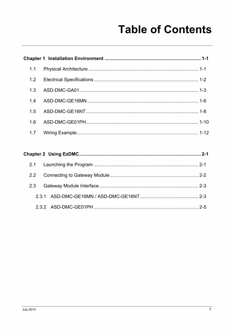
Table of Contents
Chapter 1 Installation Environment ......................................................................... 1-1
1.1 Physical Architecture ................................................................................... 1-1
1.2 Electrical Specifications ............................................................................... 1-2
1.3 ASD-DMC-GA01 .......................................................................................... 1-3
1.4 ASD-DMC-GE16MN .................................................................................... 1-6
1.5 ASD-DMC-GE16NT ..................................................................................... 1-8
1.6 ASD-DMC-GE01PH ..................................................................................... 1-10
1.7 Wiring Example ............................................................................................ 1-12
Chapter 2 Using EzDMC ............................................................................................ 2-1
2.1 Launching the Program ............................................................................... 2-1
2.2 Connecting to Gateway Module ................................................................... 2-2
2.3 Gateway Module Interface ........................................................................... 2-3
2.3.1 ASD-DMC-GE16MN / ASD-DMC-GE16NT ............................................ 2-3
2.3.2 ASD-DMC-GE01PH ............................................................................... 2-5
DMCNET Gateway Module User Guide Table of Contents
2 July 2014
(This page is intentionally left blank.)
July 2014 1-1
Chapter 1 Installation Environment
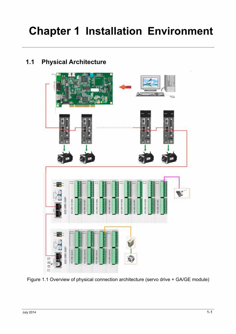
1.1 Physical Architecture
Figure 1.1 Overview of physical connection architecture (servo drive + GA/GE module)
DMCNET Gateway Module User Guide Chapter 1 Installation Environment
1-2 July 2014
1.2 Electrical Specifications
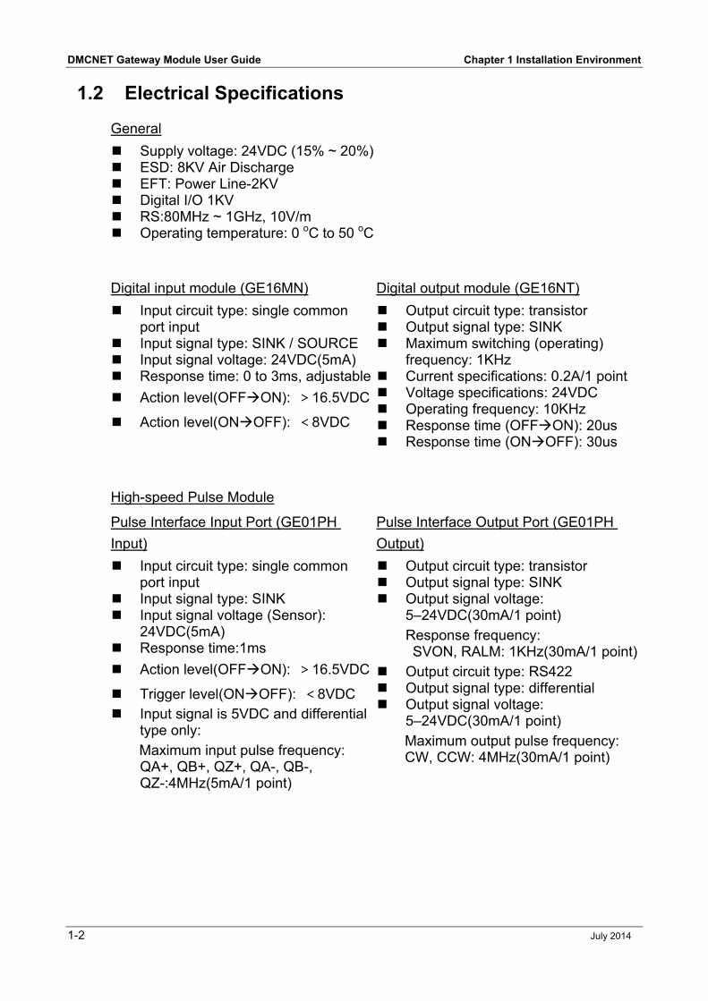
General
Supply voltage: 24VDC (15% ~ 20%) ESD: 8KV Air Discharge EFT: Power Line-2KV Digital I/O 1KV RS:80MHz ~ 1GHz, 10V/m Operating temperature: 0 oC to 50 oC
Digital input module (GE16MN) Digital output module (GE16NT)
Input circuit type: single common port input
Input signal type: SINK / SOURCE Input signal voltage: 24VDC(5mA) Response time: 0 to 3ms, adjustable
Action level(OFFON): >16.5VDC
Action level(ONOFF): <8VDC
Output circuit type: transistor Output signal type: SINK Maximum switching (operating)
frequency: 1KHz Current specifications: 0.2A/1 point Voltage specifications: 24VDC Operating frequency: 10KHz Response time (OFFON): 20us Response time (ONOFF): 30us
High-speed Pulse Module
Pulse Interface Input Port (GE01PH
Input)
Pulse Interface Output Port (GE01PH
Output)
Input circuit type: single common port input
Input signal type: SINK Input signal voltage (Sensor):
24VDC(5mA) Response time:1ms
Action level(OFFON): >16.5VDC
Trigger level(ONOFF): <8VDC Input signal is 5VDC and differential
type only:
Maximum input pulse frequency: QA+, QB+, QZ+, QA-, QB-, QZ-:4MHz(5mA/1 point)
Output circuit type: transistor Output signal type: SINK Output signal voltage:
5–24VDC(30mA/1 point)
Response frequency: SVON, RALM: 1KHz(30mA/1 point)
Output circuit type: RS422 Output signal type: differential Output signal voltage:
5–24VDC(30mA/1 point)
Maximum output pulse frequency: CW, CCW: 4MHz(30mA/1 point)
Chapter 1 Installation Environment DMCNET Gateway Module User Guide
July 2014 1-3
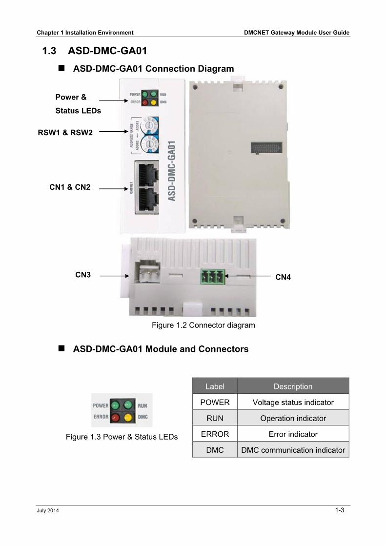
1.3 ASD-DMC-GA01
ASD-DMC-GA01 Connection Diagram
Figure 1.2 Connector diagram
ASD-DMC-GA01 Module and Connectors
Figure 1.3 Power & Status LEDs
Label Description
POWER Voltage status indicator
RUN Operation indicator
ERROR Error indicator
DMC DMC communication indicator
Power &
Status LEDs
RSW1 & RSW2
CN1 & CN2
CN3 CN4
DMCNET Gateway Module User Guide Chapter 1 Installation Environment
1-4 July 2014
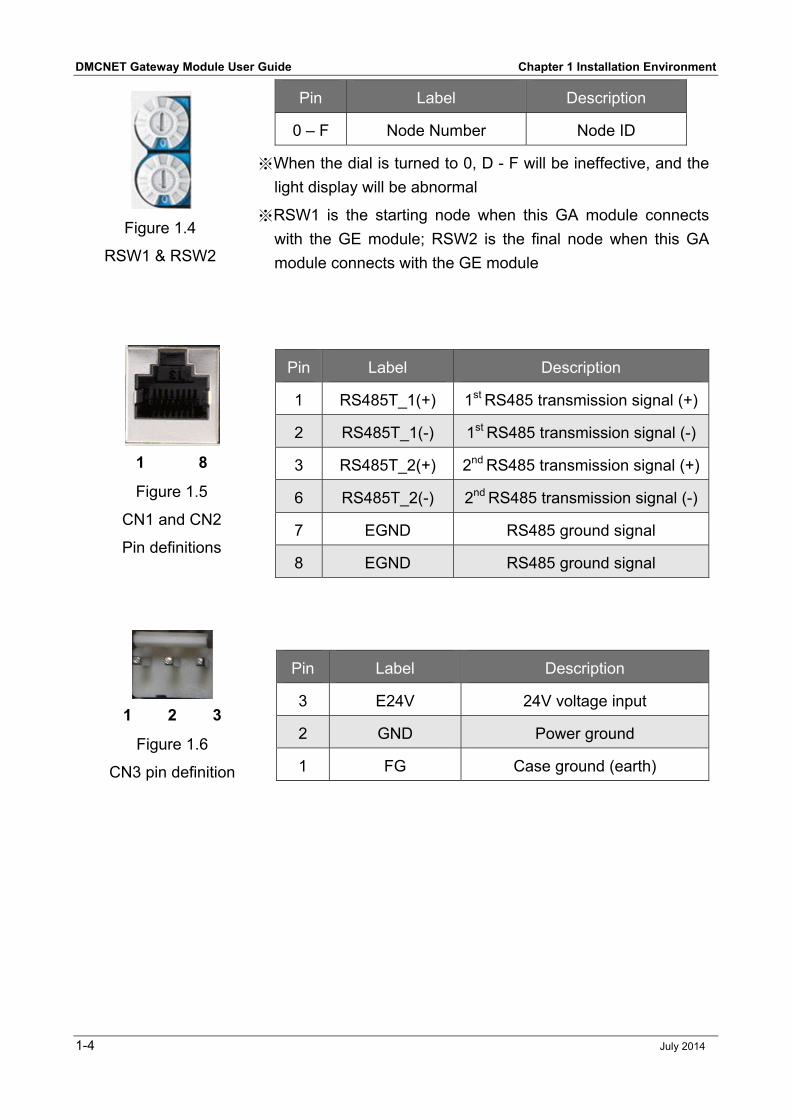
Figure 1.4
RSW1 & RSW2
Pin Label Description
0 – F Node Number Node ID
※When the dial is turned to 0, D - F will be ineffective, and the
light display will be abnormal
※RSW1 is the starting node when this GA module connects
with the GE module; RSW2 is the final node when this GA
module connects with the GE module
1 8
Figure 1.5
CN1 and CN2
Pin definitions
Pin Label Description
1 RS485T_1(+) 1st RS485 transmission signal (+)
2 RS485T_1(-) 1st RS485 transmission signal (-)
3 RS485T_2(+) 2nd RS485 transmission signal (+)
6 RS485T_2(-) 2nd RS485 transmission signal (-)
7 EGND RS485 ground signal
8 EGND RS485 ground signal
1 2 3
Figure 1.6
CN3 pin definition
Pin Label Description
3 E24V 24V voltage input
2 GND Power ground
1 FG Case ground (earth)
Chapter 1 Installation Environment DMCNET Gateway Module User Guide
July 2014 1-5
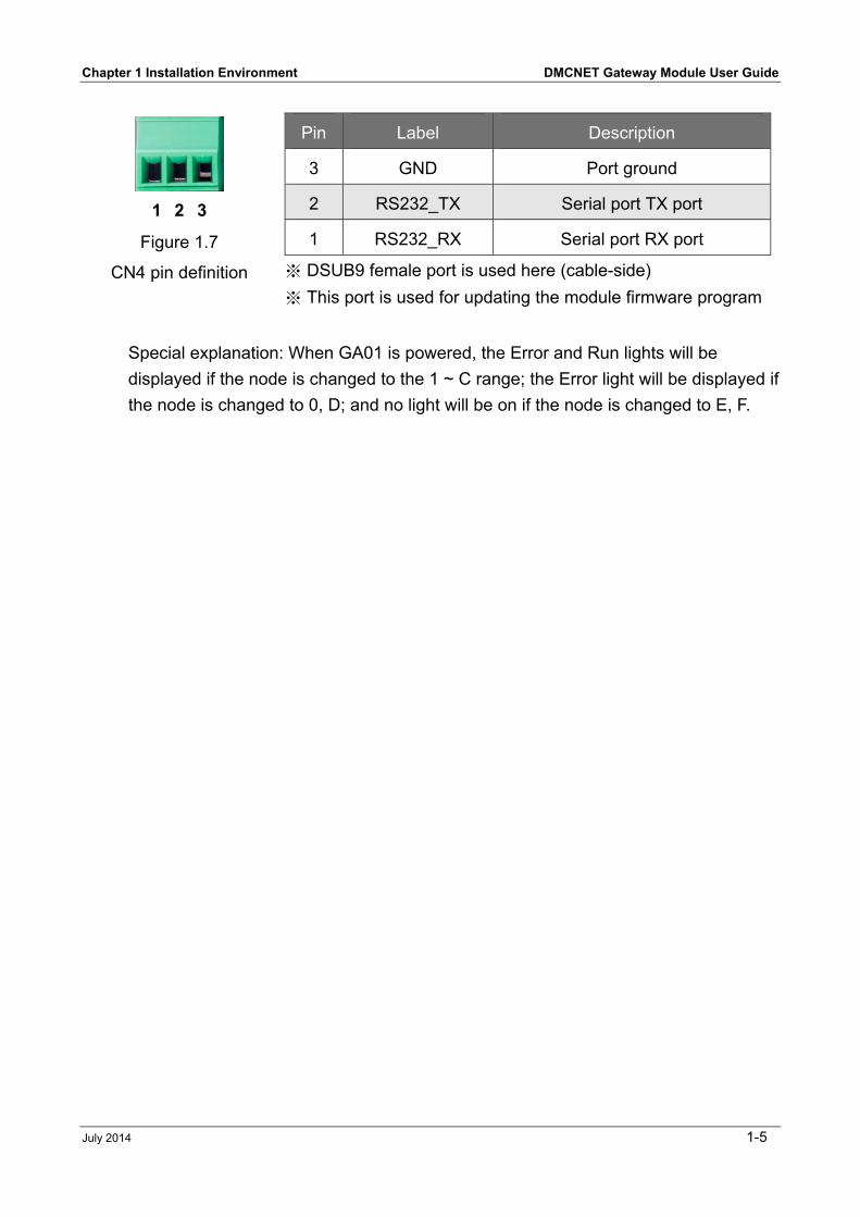
1 2 3
Figure 1.7
CN4 pin definition ※ DSUB9 female port is used here (cable-side)
※ This port is used for updating the module firmware program
Pin Label Description
3 GND Port ground
2 RS232_TX Serial port TX port
1 RS232_RX Serial port RX port
Special explanation: When GA01 is powered, the Error and Run lights will be
displayed if the node is changed to the 1 ~ C range; the Error light will be displayed if
the node is changed to 0, D; and no light will be on if the node is changed to E, F.
DMCNET Gateway Module User Guide Chapter 1 Installation Environment
1-6 July 2014
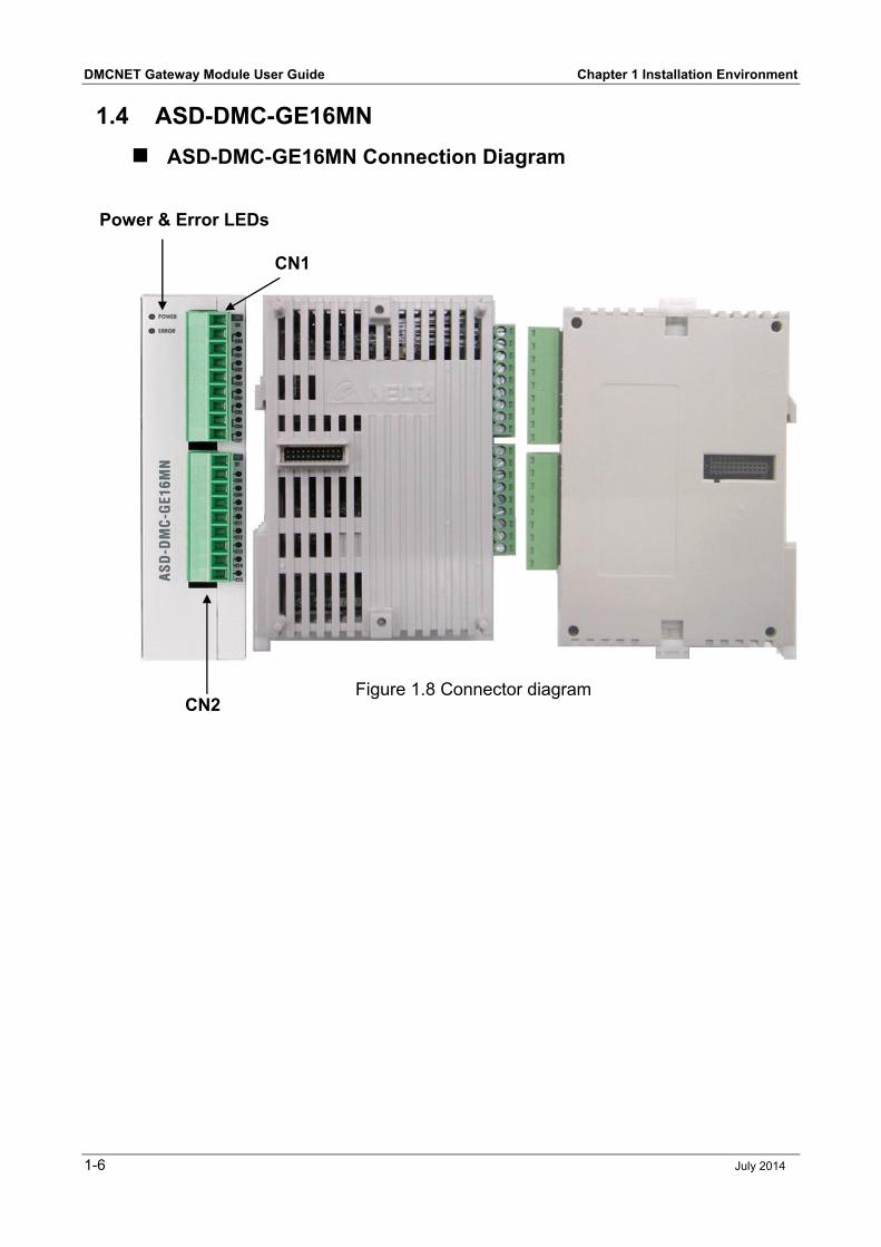
1.4 ASD-DMC-GE16MN
ASD-DMC-GE16MN Connection Diagram
Figure 1.8 Connector diagram
Power & Error LEDs
CN1
CN2
Chapter 1 Installation Environment DMCNET Gateway Module User Guide
July 2014 1-7
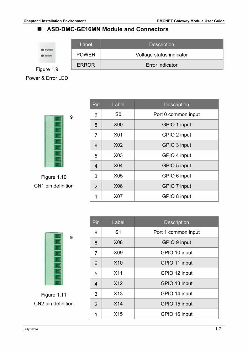
ASD-DMC-GE16MN Module and Connectors
Figure 1.10
CN1 pin definition
Pin Label Description
9 S0 Port 0 common input
8 X00 GPIO 1 input
7 X01 GPIO 2 input
6 X02 GPIO 3 input
5 X03 GPIO 4 input
4 X04 GPIO 5 input
3 X05 GPIO 6 input
2 X06 GPIO 7 input
1 X07 GPIO 8 input
Figure 1.11
CN2 pin definition
Pin Label Description
9 S1 Port 1 common input
8 X08 GPIO 9 input
7 X09 GPIO 10 input
6 X10 GPIO 11 input
5 X11 GPIO 12 input
4 X12 GPIO 13 input
3 X13 GPIO 14 input
2 X14 GPIO 15 input
1 X15 GPIO 16 input
Figure 1.9
Power & Error LED
Label Description
POWER Voltage status indicator
ERROR Error indicator
9
9
DMCNET Gateway Module User Guide Chapter 1 Installation Environment
1-8 July 2014
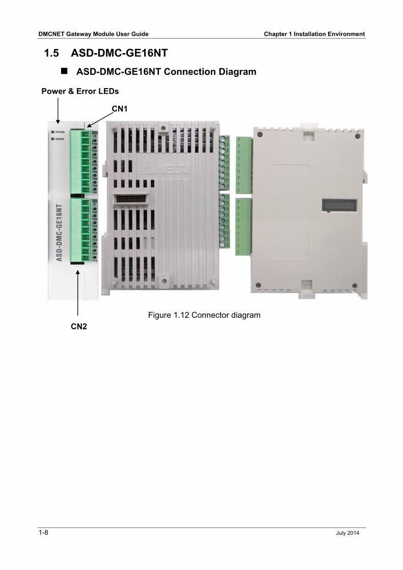
1.5 ASD-DMC-GE16NT
ASD-DMC-GE16NT Connection Diagram
Figure 1.12 Connector diagram
Power & Error LEDs
CN1
CN2
Chapter 1 Installation Environment DMCNET Gateway Module User Guide
July 2014 1-9
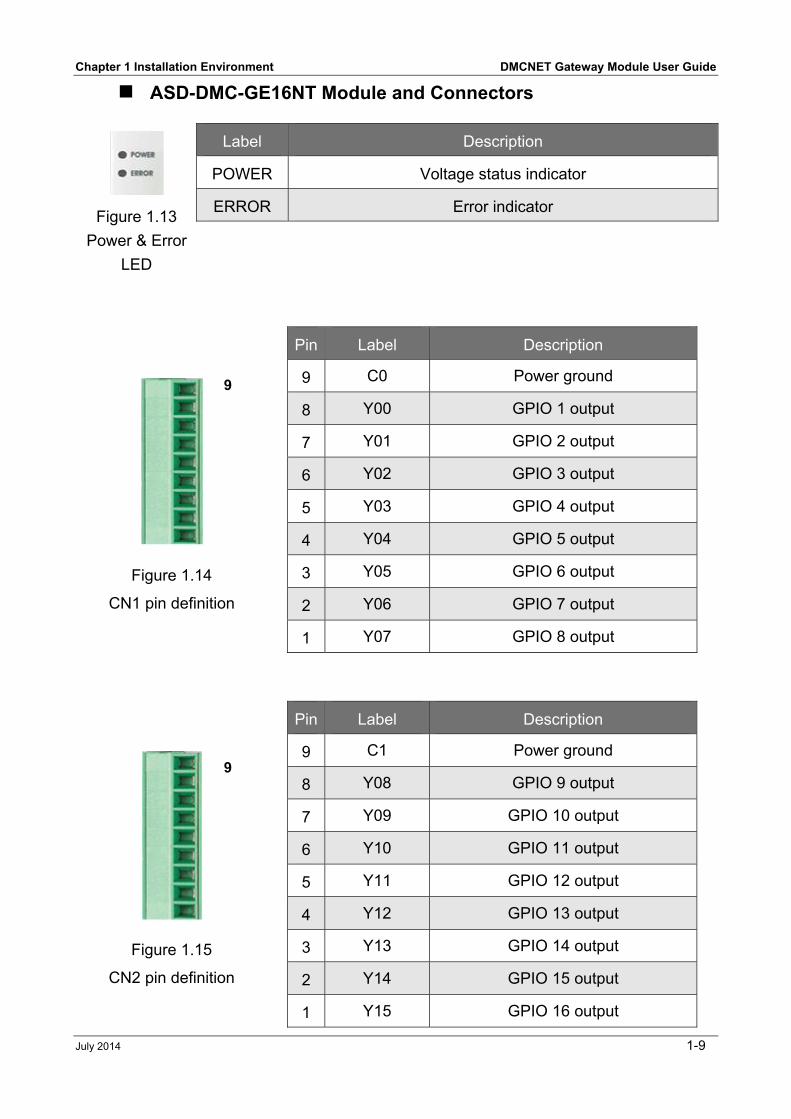
ASD-DMC-GE16NT Module and Connectors
Figure 1.14
CN1 pin definition
Pin Label Description
9 C0 Power ground
8 Y00 GPIO 1 output
7 Y01 GPIO 2 output
6 Y02 GPIO 3 output
5 Y03 GPIO 4 output
4 Y04 GPIO 5 output
3 Y05 GPIO 6 output
2 Y06 GPIO 7 output
1 Y07 GPIO 8 output
Figure 1.15
CN2 pin definition
Pin Label Description
9 C1 Power ground
8 Y08 GPIO 9 output
7 Y09 GPIO 10 output
6 Y10 GPIO 11 output
5 Y11 GPIO 12 output
4 Y12 GPIO 13 output
3 Y13 GPIO 14 output
2 Y14 GPIO 15 output
1 Y15 GPIO 16 output
Figure 1.13
Power & Error
LED
Label Description
POWER Voltage status indicator
ERROR Error indicator
9
9
DMCNET Gateway Module User Guide Chapter 1 Installation Environment
1-10 July 2014
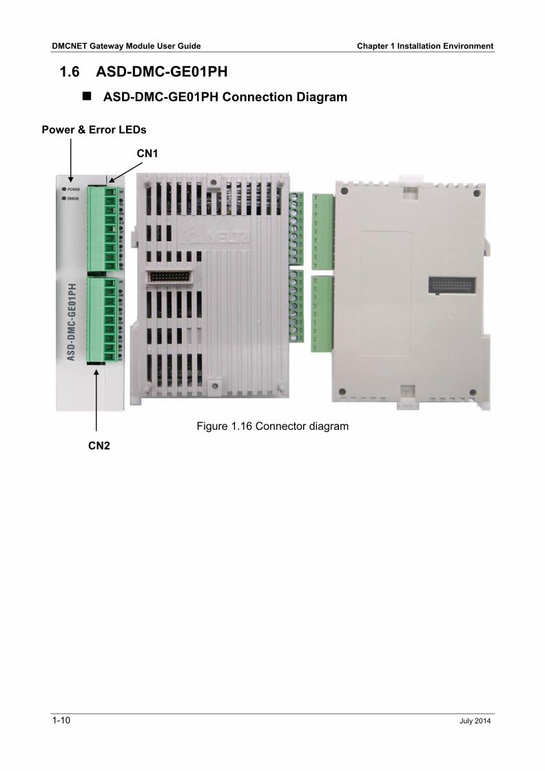
1.6 ASD-DMC-GE01PH
ASD-DMC-GE01PH Connection Diagram
Figure 1.16 Connector diagram
Power & Error LEDs
CN1
CN2
Chapter 1 Installation Environment DMCNET Gateway Module User Guide
July 2014 1-11
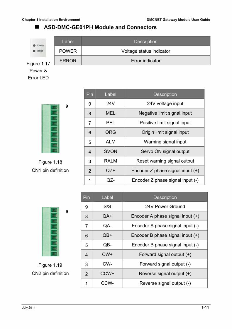
ASD-DMC-GE01PH Module and Connectors
Figure 1.18
CN1 pin definition
Pin Label Description
9 24V 24V voltage input
8 MEL Negative limit signal input
7 PEL Positive limit signal input
6 ORG Origin limit signal input
5 ALM Warning signal input
4 SVON Servo ON signal output
3 RALM Reset warning signal output
2 QZ+ Encoder Z phase signal input (+)
1 QZ- Encoder Z phase signal input (-)
Figure 1.19
CN2 pin definition
Pin Label Description
9 S/S 24V Power Ground
8 QA+ Encoder A phase signal input (+)
7 QA- Encoder A phase signal input (-)
6 QB+ Encoder B phase signal input (+)
5 QB- Encoder B phase signal input (-)
4 CW+ Forward signal output (+)
3 CW- Forward signal output (-)
2 CCW+ Reverse signal output (+)
1 CCW- Reverse signal output (-)
Figure 1.17
Power &
Error LED
Label Description
POWER Voltage status indicator
ERROR Error indicator
9
9
DMCNET Gateway Module User Guide Chapter 1 Installation Environment
1-12 July 2014
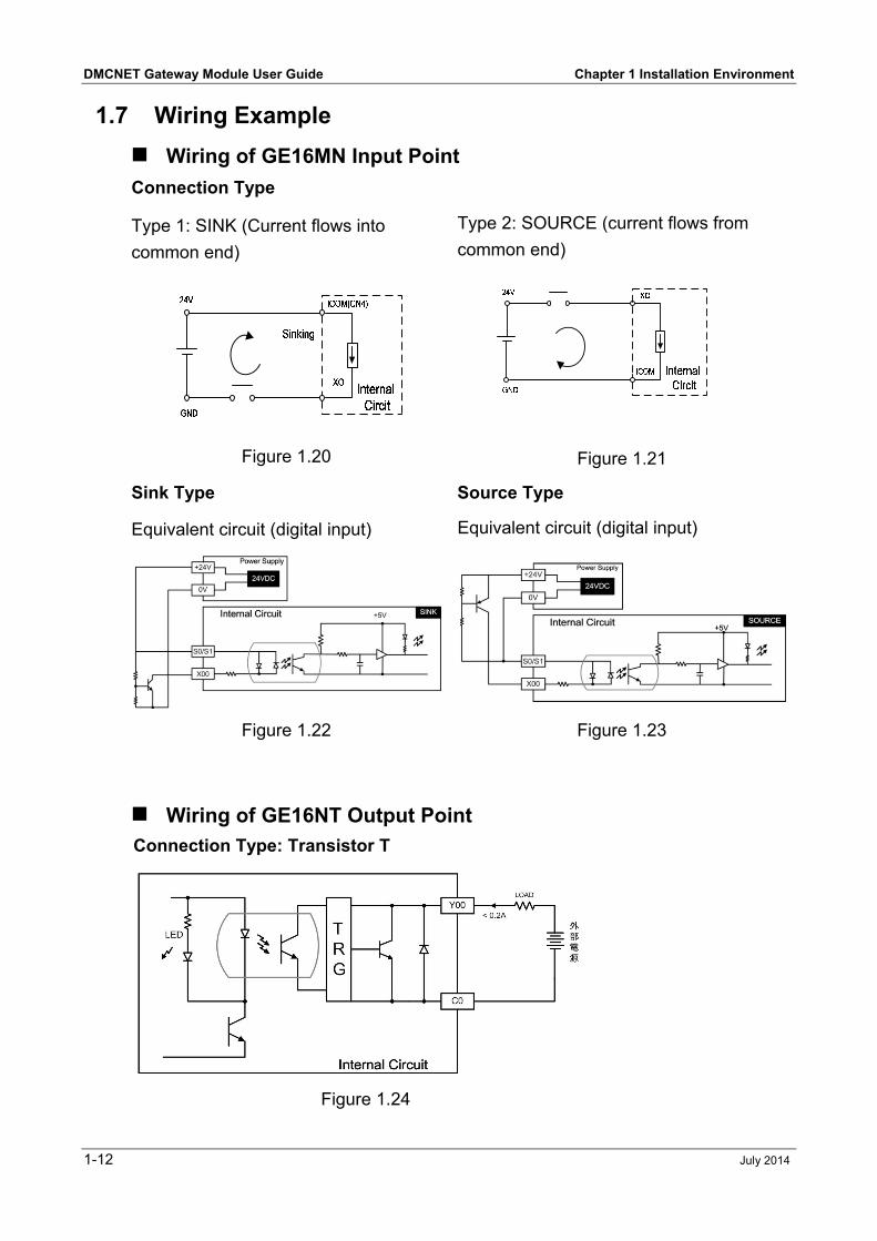
1.7 Wiring Example
Wiring of GE16MN Input Point Connection Type
Type 1: SINK (Current flows into
common end)
Type 2: SOURCE (current flows from
common end)
Figure 1.20
Figure 1.21
Sink Type Source Type
Equivalent circuit (digital input) Equivalent circuit (digital input)
Figure 1.22 Figure 1.23
Wiring of GE16NT Output Point Connection Type: Transistor T
Figure 1.24
Chapter 1 Installation Environment DMCNET Gateway Module User Guide
July 2014 1-13
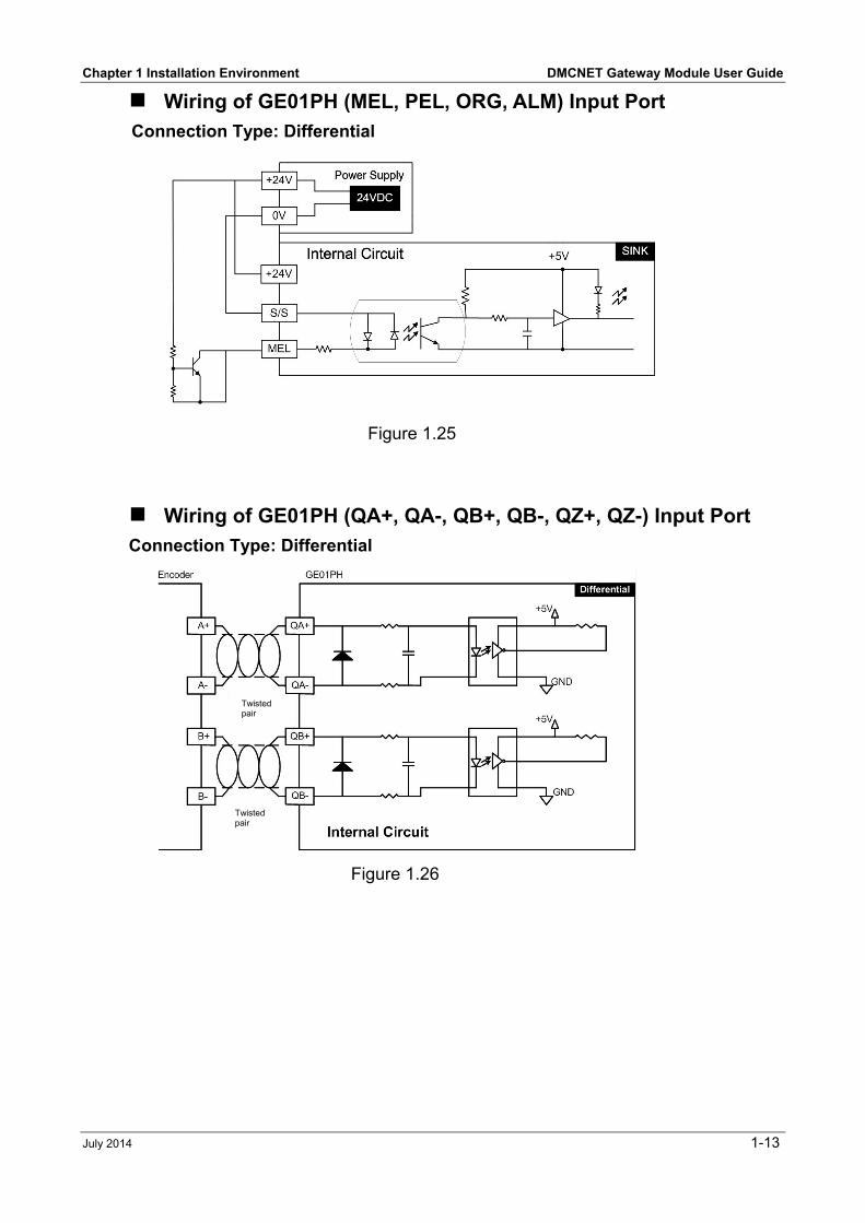
Wiring of GE01PH (MEL, PEL, ORG, ALM) Input Port Connection Type: Differential
Figure 1.25
Wiring of GE01PH (QA+, QA-, QB+, QB-, QZ+, QZ-) Input Port Connection Type: Differential
Figure 1.26
Twisted pair
Twisted pair
DMCNET Gateway Module User Guide Chapter 1 Installation Environment
1-14 July 2014
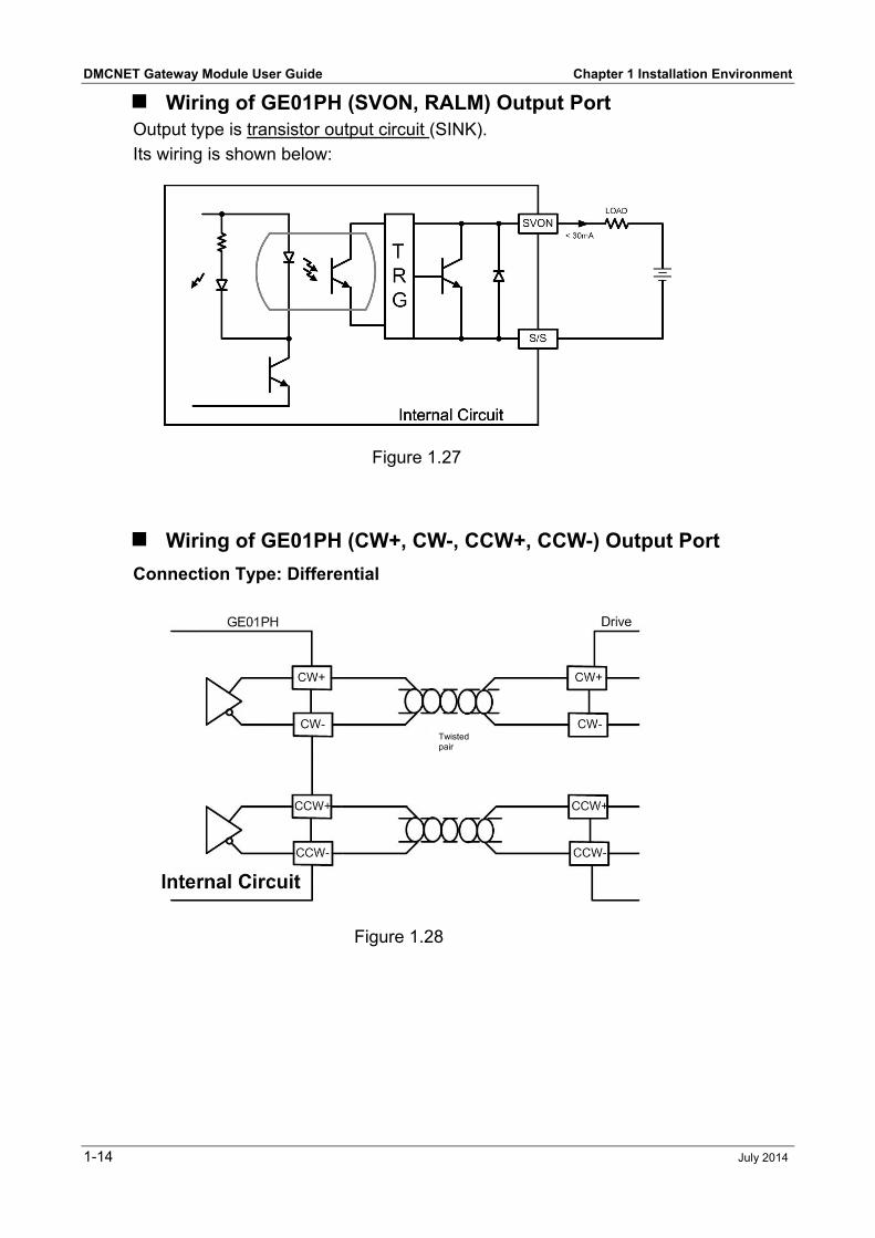
Wiring of GE01PH (SVON, RALM) Output Port Output type is transistor output circuit (SINK).
Its wiring is shown below:
Figure 1.27
Wiring of GE01PH (CW+, CW-, CCW+, CCW-) Output Port Connection Type: Differential
Figure 1.28
Twisted pair
July 2014 2-1
Chapter 2 Using EzDMC
2.1 Launching the Program
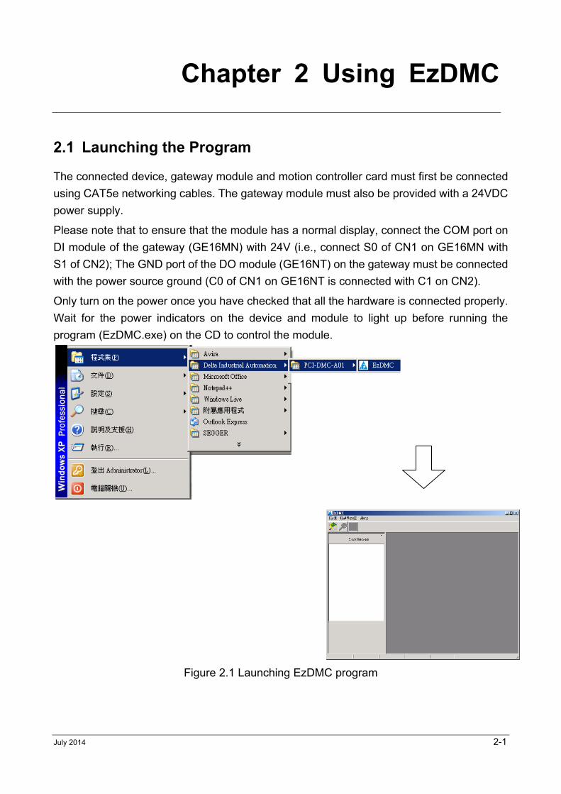
The connected device, gateway module and motion controller card must first be connected
using CAT5e networking cables. The gateway module must also be provided with a 24VDC
power supply.
Please note that to ensure that the module has a normal display, connect the COM port on
DI module of the gateway (GE16MN) with 24V (i.e., connect S0 of CN1 on GE16MN with
S1 of CN2); The GND port of the DO module (GE16NT) on the gateway must be connected
with the power source ground (C0 of CN1 on GE16NT is connected with C1 on CN2).
Only turn on the power once you have checked that all the hardware is connected properly.
Wait for the power indicators on the device and module to light up before running the
program (EzDMC.exe) on the CD to control the module.
Figure 2.1 Launching EzDMC program
DMCNET Gateway Module User Guide Chapter 2 Using EzDMC
2-2 July 2014
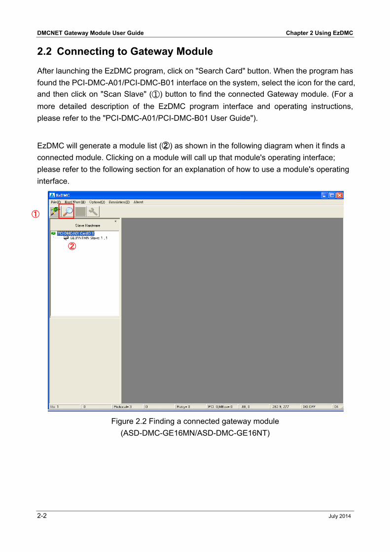
2.2 Connecting to Gateway Module
After launching the EzDMC program, click on "Search Card" button. When the program has
found the PCI-DMC-A01/PCI-DMC-B01 interface on the system, select the icon for the card,
and then click on "Scan Slave" (①) button to find the connected Gateway module. (For a
more detailed description of the EzDMC program interface and operating instructions,
please refer to the "PCI-DMC-A01/PCI-DMC-B01 User Guide").
EzDMC will generate a module list (➁) as shown in the following diagram when it finds a
connected module. Clicking on a module will call up that module's operating interface;
please refer to the following section for an explanation of how to use a module's operating
interface.
Figure 2.2 Finding a connected gateway module
(ASD-DMC-GE16MN/ASD-DMC-GE16NT)
①
➁
Chapter 2 Using EzDMC DMCNET Gateway Module User Guide
July 2014 2-3
2.3 Gateway Module Interface
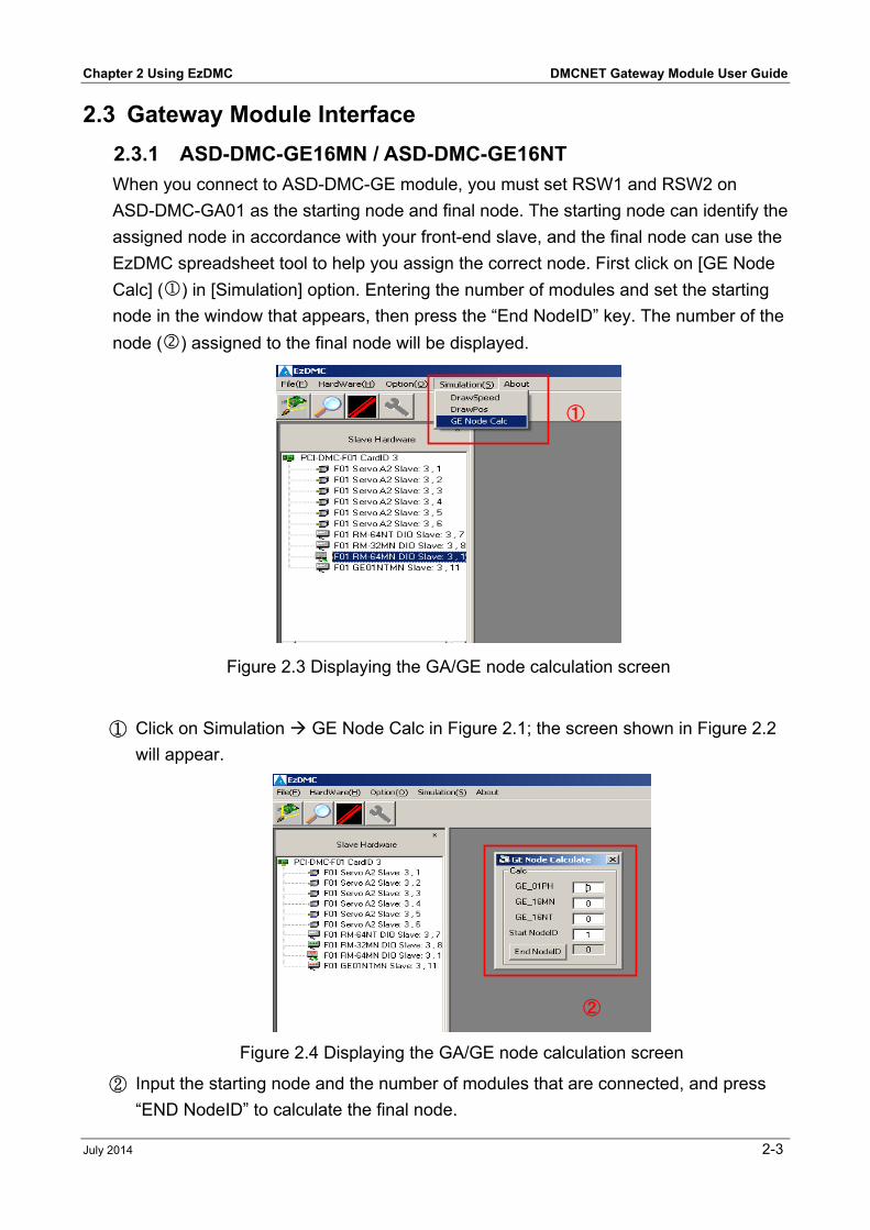
2.3.1 ASD-DMC-GE16MN / ASD-DMC-GE16NT When you connect to ASD-DMC-GE module, you must set RSW1 and RSW2 on
ASD-DMC-GA01 as the starting node and final node. The starting node can identify the
assigned node in accordance with your front-end slave, and the final node can use the
EzDMC spreadsheet tool to help you assign the correct node. First click on [GE Node
Calc] () in [Simulation] option. Entering the number of modules and set the starting
node in the window that appears, then press the “End NodeID” key. The number of the
node () assigned to the final node will be displayed.
Figure 2.3 Displaying the GA/GE node calculation screen
① Click on Simulation GE Node Calc in Figure 2.1; the screen shown in Figure 2.2
will appear.
Figure 2.4 Displaying the GA/GE node calculation screen
② Input the starting node and the number of modules that are connected, and press
“END NodeID” to calculate the final node.
①
➁
DMCNET Gateway Module User Guide Chapter 2 Using EzDMC
2-4 July 2014
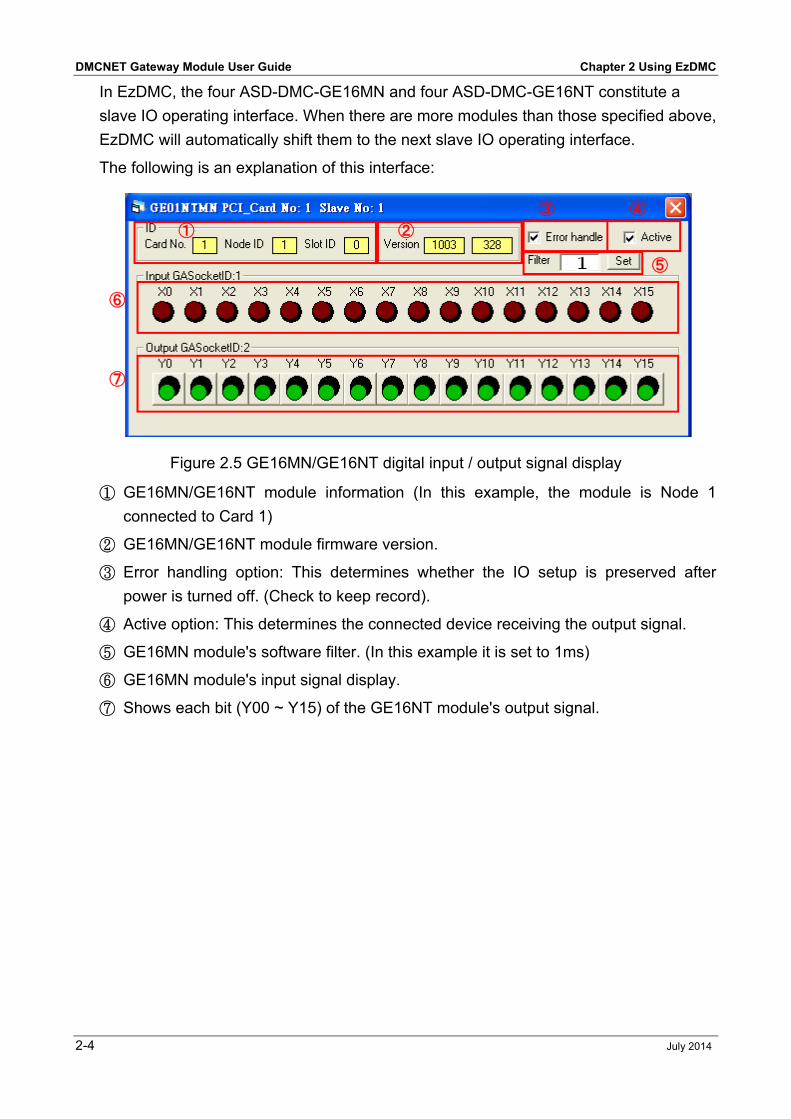
In EzDMC, the four ASD-DMC-GE16MN and four ASD-DMC-GE16NT constitute a
slave IO operating interface. When there are more modules than those specified above,
EzDMC will automatically shift them to the next slave IO operating interface.
The following is an explanation of this interface:
Figure 2.5 GE16MN/GE16NT digital input / output signal display
① GE16MN/GE16NT module information (In this example, the module is Node 1
connected to Card 1)
② GE16MN/GE16NT module firmware version.
③ Error handling option: This determines whether the IO setup is preserved after
power is turned off. (Check to keep record).
④ Active option: This determines the connected device receiving the output signal.
⑤ GE16MN module's software filter. (In this example it is set to 1ms)
⑥ GE16MN module's input signal display.
⑦ Shows each bit (Y00 ~ Y15) of the GE16NT module's output signal.
① ➁
➂ ➃
➄
➅
➆
Chapter 2 Using EzDMC DMCNET Gateway Module User Guide
July 2014 2-5
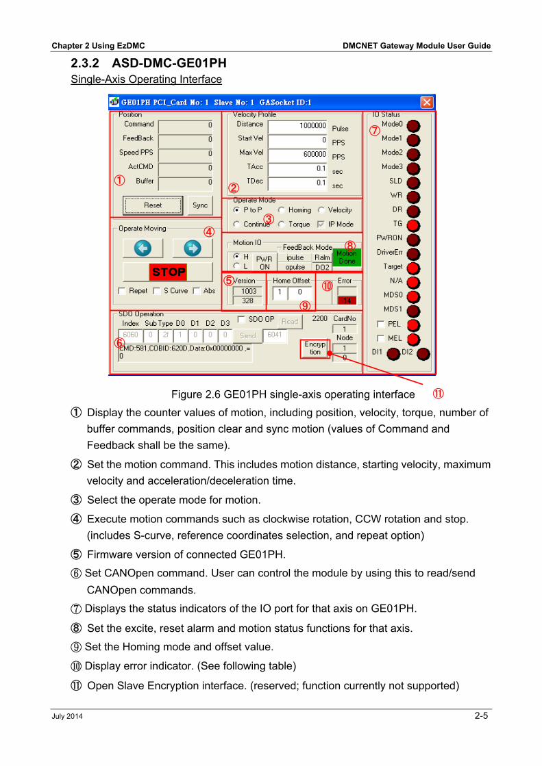
2.3.2 ASD-DMC-GE01PH Single-Axis Operating Interface
Figure 2.6 GE01PH single-axis operating interface
➀ Display the counter values of motion, including position, velocity, torque, number of
buffer commands, position clear and sync motion (values of Command and
Feedback shall be the same).
➁ Set the motion command. This includes motion distance, starting velocity, maximum
velocity and acceleration/deceleration time.
➂ Select the operate mode for motion.
➃ Execute motion commands such as clockwise rotation, CCW rotation and stop.
(includes S-curve, reference coordinates selection, and repeat option)
➄ Firmware version of connected GE01PH.
⑥ Set CANOpen command. User can control the module by using this to read/send
CANOpen commands.
⑦ Displays the status indicators of the IO port for that axis on GE01PH.
➇ Set the excite, reset alarm and motion status functions for that axis.
⑨ Set the Homing mode and offset value.
⑩ Display error indicator. (See following table)
⑪ Open Slave Encryption interface. (reserved; function currently not supported)
➀ ➁
➆
➂ ➃
➇
➄
⑨
⑩
➅
⑪
DMCNET Gateway Module User Guide Chapter 2 Using EzDMC
2-6 July 2014
Indicator Description How to clear
the indicator
Indicator Description How to clear
the indicator
0 Normal None
(Indicator does
not come ON)
15 Collision with
machine
positive limit
Move away
from positive
limit
9 Velocity limit
exceeded
Reset the
velocity
283 Collision with
software
positive limit
Move away
from software
positive limit
13 EMG Press the
"RALM" button
285 Collision with
software
negative limit
Move away
from software
negative limit
14 Collision with
machine
negative limit
Move away
from negative
limit
299 Invalid
operation
Press the
"RALM" button
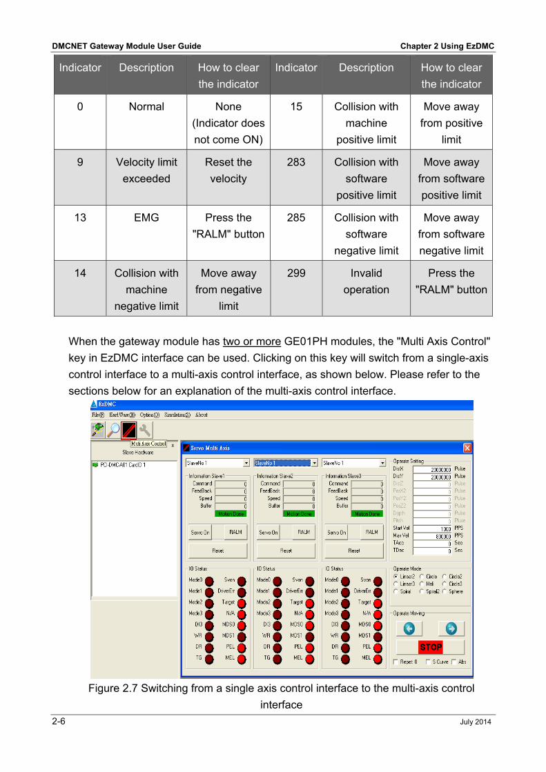
When the gateway module has two or more GE01PH modules, the "Multi Axis Control"
key in EzDMC interface can be used. Clicking on this key will switch from a single-axis
control interface to a multi-axis control interface, as shown below. Please refer to the
sections below for an explanation of the multi-axis control interface.
Figure 2.7 Switching from a single axis control interface to the multi-axis control
interface
Chapter 2 Using EzDMC DMCNET Gateway Module User Guide
July 2014 2-7
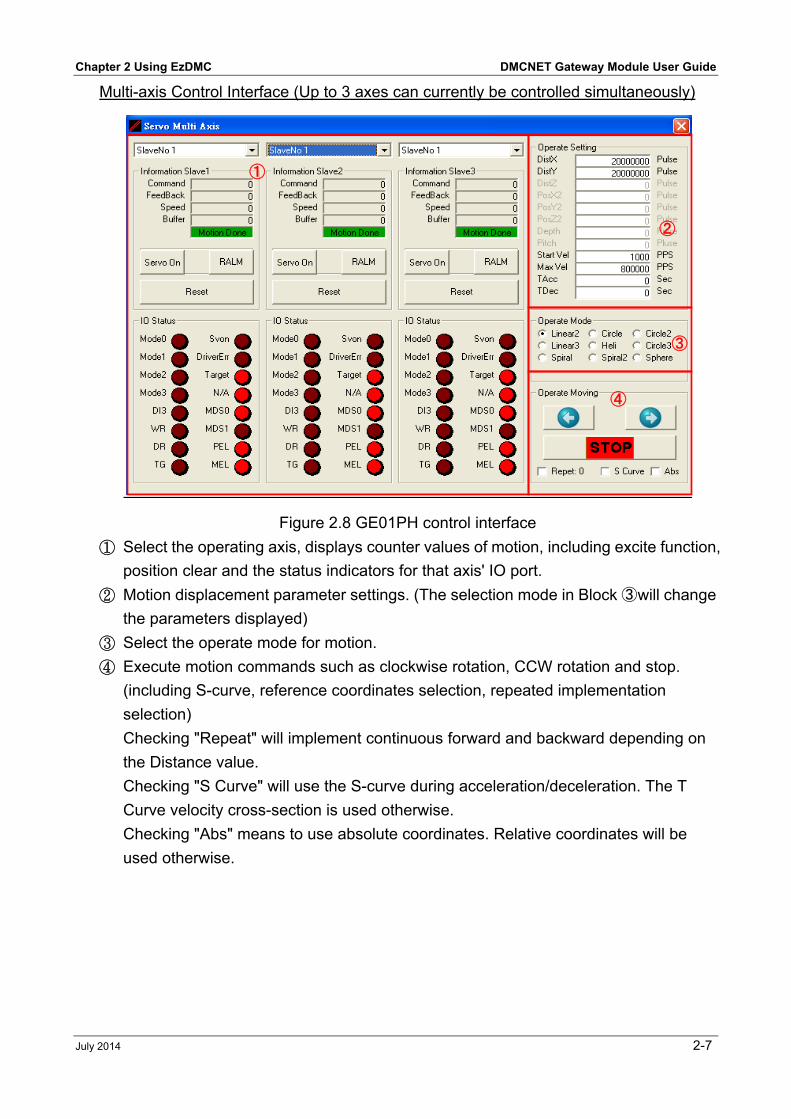
Multi-axis Control Interface (Up to 3 axes can currently be controlled simultaneously)
Figure 2.8 GE01PH control interface
① Select the operating axis, displays counter values of motion, including excite function,
position clear and the status indicators for that axis' IO port.
② Motion displacement parameter settings. (The selection mode in Block ➂ will change
the parameters displayed) ③ Select the operate mode for motion. ④ Execute motion commands such as clockwise rotation, CCW rotation and stop.
(including S-curve, reference coordinates selection, repeated implementation
selection)
Checking "Repeat" will implement continuous forward and backward depending on
the Distance value.
Checking "S Curve" will use the S-curve during acceleration/deceleration. The T
Curve velocity cross-section is used otherwise.
Checking "Abs" means to use absolute coordinates. Relative coordinates will be
used otherwise.
➀
➁
➂
➃

DMCNET Gateway Module User Guide Chapter 2 Using EzDMC
2-8 July 2014
(This page is intentionally left blank.)