Gas sweetening Plant
62
Prepared By: SYED HAIDER ABBAS DEPARTMENT OF CHEMICAL ENGINEERING COMSATS INSTITUTE OF INFORMATION TECHNOLOGY Email: [email protected] INTERNSHIP REPORT OMV KADANWARI PLANT
-
Upload
syed-haider-abbas-bukhari -
Category
Documents
-
view
245 -
download
3
Transcript of Gas sweetening Plant
8102019 Gas sweetening Plant
httpslidepdfcomreaderfullgas-sweetening-plant 162
Prepared By
SYED HAIDER ABBAS
DEPARTMENT OF CHEMICAL ENGINEERING
COMSATS INSTITUTE OF INFORMATION TECHNOLOGY
Email haidy_42hotmailcom
INTERNSHIP REPORT OMV KADANWARI PLANT
8102019 Gas sweetening Plant
httpslidepdfcomreaderfullgas-sweetening-plant 262
8102019 Gas sweetening Plant
httpslidepdfcomreaderfullgas-sweetening-plant 362
TABLE OF CONTENTS
Page
Introduction to OMV 1
Scope of Plant 2
Process description 3
Wellhead and Christmas Tree 6
Types of Christmas Tree 10
Well Head Control Panel 12
Chemical Injection 13
Water Conning 14
Corrosion and Protection 15
Pigs and Pigging operations 17
Compressors 18
Front End Compressor (Reciprocating) 19
Centrifugal Compressors 23
Separators 24
Membranes 29
Working principle of Membranes 31
Advantages of Membrane System 36
Sorption 39
Absorption 39
Adsorption 40
Pre-treatment 41
8102019 Gas sweetening Plant
httpslidepdfcomreaderfullgas-sweetening-plant 462
Memguard 42
H2S Polisher 46
Recycle Compressor 48
Sales Gas Compressor 49
Cooling Towers 50
Fin Fan Coolers 53
Produced Water 54
Incinerator 54
Control System 55
Safety System 55
8102019 Gas sweetening Plant
httpslidepdfcomreaderfullgas-sweetening-plant 562
P a g e | 1
Introduction to OMV
OMV is Austriarsquos lar gest listed industrial company As the leading oil and gas
group in Central Europe OMV is active in Refining and Marketing (RampM) in 13
countries and in Exploration and Production (EampP) OMV is active in 18 countries
on five continents In Pakistan OMV has been active as an operator and partner
since 1990 In the years to date OMV (Pakistan) has established itself as the
largest international gas producer in Pakistan with an operated volume of more
than 110000 barrels of oil equivalent per day from Kadanwari-Miano and Sawan
fields This represents about 16 of the total gas produced in Pakistan The firstsignificant achievement was the discovery of the Miano gas reservoir in the Thar
Desert of Sindh province It came about by the end of 1993 just three years after
OMV came to Pakistan The second major breakthrough came five years later ie
in 1998 from the field named Sawan again in the same area of Sindh Sawan
was and still is one of the largest discoveries of gas reserves in Pakistan In a
record nineteen months from the ground-breaking ceremony in January 2002 of
the Sawan Gas Plant OMV was able to sell its raw gas by July 2003 Parallel to
the Sawan development OMV also took over the operator-ship of the Kadanwari
Gas Processing Plant on 1st January 2003 from Lasmo currently ENI OMV
remained quite aggressive on new developments and Kadanwari plant gas
processing capacity was enhanced to 232 MMscfd while Sawan plant capacity
has been enhanced to 400 MMscfd To further meet raw gas requirements
development drilling was continued successfully for both fields Besides these
activities carried out in OMV Pakistanrsquos core area OMV is pursuing new projects
in other parts of Pakistan Health Safety and Environmental standards are
parallel to the highest international level and second to none in the local
perspective OMV has strong commitment to reduce emissions to the
environment To achieve the same an ldquoEmission Reductionrdquo project has been
initiated for Kadanwari Plant
8102019 Gas sweetening Plant
httpslidepdfcomreaderfullgas-sweetening-plant 662
P a g e | 2
Scope of Plant
Carbon dioxide and hydrogen sulfide which fall into the category of acid gasesare commonly found in natural gas streams at levels as high as 80 In
combination with water they are highly corrosive and can rapidly destroy
pipelines and equipment unless they are partially removed or exotic and
expensive materials of construction are used Hydrogen sulfide is toxic and at
relatively modest levels can be life threatening Carbon dioxide also reduces the
heating value of a natural gas stream and wastes pipeline capacity In LNG
plants CO2 must be removed to prevent freezing in the low-temperature chillers
Therefore the composition of gas is adjusted as per limits prescribed by SNGPL
(Sui Southern Gas Pakistan Limited) and is sold to the government The gas is
injected to the SNGPL main facility at a pressure of 1100 psi
The sales gas specifications are as follows
CO2 Maximum = 3
H2S Maximum = 38 ppm
CV Minimum = 920 BtuscfWater = 7lbMMscf
OMV Kadanwai facility sale gas composition
8102019 Gas sweetening Plant
httpslidepdfcomreaderfullgas-sweetening-plant 762
P a g e | 3
OMV Kadanwai facility feed gas composition
Process Description
Gas from Kadanwari High pressure wells is routed to Kadanwari High Pressure
slug catcher Gas from Kadanwari low pressure wells is routed to Kadanwari low
pressure slug catcher and is fed to 2 stage Front End Compressor (FEC) to
increase the pressure up to production pressure Gas from FEC is fed to high
pressure stream flowing into Kadanwari High Pressure slug catcher The gas
from Miano wells is fed to Miano Slug Catcher
Kadanwari and Miano gas streams after separately metered are fed to a common
header which splits into two identical skids A and B Here we will discuss one
skid in common Each skid is routed to fin fan coolers where it is cooled and fed
to Inlet separator where water and heavy hydrocarbons are removed from feed
gas The condensate from all units is sent to produce water system
8102019 Gas sweetening Plant
httpslidepdfcomreaderfullgas-sweetening-plant 862
P a g e | 4
The gas then passes through pretreatment skid which consists of following units
Feed Cooler
Feed Gas Scrubber
Filter Coalescer
Feed Gas Heater
Activated Carbon Guard Filter
Particle Filter
Its main function is to remove contaminants from gas such as dust lube oils
heavy hydrocarbons etc which may poison or reduce efficiency of membrane
unit
After pretreatment gas is fed to Molecular Sieve Absorbers (Memguard Units)
which ensures gas supplied to membranes is up to membrane standards of UOP
(vendor of membrane system) It removes all moisture and heavy hydrocarbons
from gas stream
Pretreated gas is now fed to the primary membranes The permeate stream (rich
in CO2) is sent to recycle membranes after passing through recycle compressor
and recycle pretreatment The permeate stream of recycle membranes is used as
regenerative medium for Memguard units and rest is sent to incinerator and
burnt The residual gas (rich in CH4) from primary membrane and recycle
membranes (all skids) is sent to H2S polishers via a common header
H2S polisher unit reduce the hydrogen sulfide level to the sales limit The gas is
now metered after compressing in sales gas compressor and is sent to SNGPL
trunk line after metering
Water is remove from condensate at produced water system by a three phase
separator The condensate is sold to refinery Major quantity is exported to
various industries
8102019 Gas sweetening Plant
httpslidepdfcomreaderfullgas-sweetening-plant 962
P a g e | 5
Figure Overall plant Process Flow Diagram
8102019 Gas sweetening Plant
httpslidepdfcomreaderfullgas-sweetening-plant 1062
P a g e | 6
Wellhead
A wellhead is the component at the surface of an oil or gas well that provides the
structural and pressure-containing interface for the drilling and production
equipment Its function is to maintain surface control of the well It forms a seal to
prevent well fluids from leaking or blowing at the surface They are rated for
working pressure of 2000 psi to 15000 psi (or greater)
When the well has been drilled and it is ready to provide an interface with the
reservoir rock and a tubular channel for the well fluids The surface pressure
control is provided by a Christmas tree which is installed on top of the wellhead
with valves and choke equipment to control the flow of well fluids during
production
Christmas tree
A Christmas tree is an assembly of valves spools and fittings used for an oil
well gas well water injection well gas injection well condensate well and other
types of wells
The primary function of a tree is to control the flow usually oil or gas out of the
well When the well and facilities are ready to produce and receive oil or gas tree
valves are opened and the formation fluids are allowed to go through a flow line
This leads to a processing facility A tree often provides numerous additional
functions including chemical injection points well intervention means pressure
relief means monitoring points (such as pressure temperature corrosion
erosion sand detection flow rate flow composition valve and choke position
feedback) and connection points for devices such as down hole pressure andtemperature transducers (DHPT) On producing wells chemicals or alcohols or
oil distillates may be injected to preclude production problems (such as
blockages)
The control system attached to the tree controls the down-hole safety valve
(SCSSV) while the tree acts as an attachment and means of the control system
to the down-hole safety valve
8102019 Gas sweetening Plant
httpslidepdfcomreaderfullgas-sweetening-plant 1162
P a g e | 7
Figure 1
Well Head and Christmas Tree
8102019 Gas sweetening Plant
httpslidepdfcomreaderfullgas-sweetening-plant 1262
P a g e | 8
Master Valves
The two lower valves are called the master valves Master valves are normally in
the fully open position and are never opened or closed when the well is flowing
(except in an emergency) to prevent erosion of the valve sealing surfaces They
are gate type valves
1 Lower Master Valve (LMV)
2 Upper Master Valve (UMV)
The lower master valve will normally be manually operated while the upper
master valve is often hydraulically actuated allowing it to be used as a means of
remotely shutting in the well in the event of emergency
Wing Valve
A wing valve is normally used to shut in the well when flowing thus preserving
the master valves for positive shut off for maintenance purposes The wing
valve can be a gate valve or ball valve Hydraulic operated wing valves are
usually built to be fail safe closed meaning they require active hydraulic pressure
to stay open This feature means that if control fluid fails the well will
automatically shut itself in without operator action
In Kadanwari well sites there is only one manually operated wing valve On the
other hand at Miano well sites there are two wing valves one being operated
manually and other hydraulically
Production Wing Valve
The right hand valve is often called the flow wing valve or the production wing
valve because it provides flow path for hydrocarbons to production facility
Kill wing valve
The left hand valve is often called the kill wing valve It is primarily used for
injection of fluids such as corrosion inhibitors or methanol to prevent hydrate
formation It is typically manually operated It can kill the well temporarily be
injection brine solution which provides a pressure head to well and temporarily
8102019 Gas sweetening Plant
httpslidepdfcomreaderfullgas-sweetening-plant 1362
P a g e | 9
suspends it for maintenance of well head Also it is used to permanently kill the
well A chemical is injected down the well that seals the piping down the well and
kills the well permanently
Swab valve
The swab valve is used to gain access to the well for wire line operations
intervention and other work over procedure On top of it is a tree adapter
and cap that will mate with various equipment For such operations a
lubricator is assembled up onto the top of the tree and the wire or coil is lowered
through the lubricator through swab valve and into the well This valve is typically
manually operated
Choke
A choke holds back pressure by restricting the flow opening at the well head This
is done to make better use of the gas for natural gas lift and to control the bottom-
hole pressure for recovery reasons
CHECK VALVE
The check is introduced in production flow line to prevent any reverse flow from
the line into the well It has a hinged flap which lifts to permit normal flow but
closes to prevent reverse flow
TOP ADAPTOR
The top adaptor is a fitting on top of the swab valve with a threaded connection
During normal well operations a pressure gauge is fitted to monitor flowing and
shut in wellhead pressures However during well service operations the cap can
be removed to allow installation of lubricators for wire-line operations
SCSSSV (Surface Control Sub Surface Safety Valve)
A subsurface safety valve is essentially a shutdown valve installed at the upper
wellbore for emergency shutdown to protect the production tubing and wellhead
in case of overpressure Subsurface safety valves can offer a barrier against flow
in the event of a wellhead collapse or other disastrous event Purpose of asubsurface safety valve (SSSV) is to avoid the ultimate disaster which can result
8102019 Gas sweetening Plant
httpslidepdfcomreaderfullgas-sweetening-plant 1462
P a g e | 10
in release of reservoir fluids to the surroundings This makes SSSV a very
important component of a well completion
A subsurface safety valve is typically a uni-directional flapper valve directed in
such a way that the flappers open downwards when pressure is applied from an
upward direction The flapper can only open in the downward direction So even if
high pressure is applied by the well fluids from a
downward direction a safety valve can remain
closed This makes a subsurface safety valve fail-
safe To open the valve hydraulic signal is sent from
the surface well control panel This hydraulic
pressure is responsible for keeping the flappers of
SSSV open and loss of hydraulic pressure result in
closing of the valve Thus wellbore can be isolated in
case of system failure or damage to the surface
facilities
Types of Christmas tree
There are two types of Christmas Tree
1 Solid block
2 Conventional
The solid block Christmas Tree has a central solid unit holding several valves
in a pre-constructed block Their advantage is the reduction in potential leak
paths and their higher pressure rating (Fig 2)
The conventional Christmas Tree is built up from individual valves bolted
together to form an assembly (Fig 3)
8102019 Gas sweetening Plant
httpslidepdfcomreaderfullgas-sweetening-plant 1562
P a g e | 11
Figure 2
Figure 3
8102019 Gas sweetening Plant
httpslidepdfcomreaderfullgas-sweetening-plant 1662
P a g e | 12
Wellhead Control Panel
Wellhead control panel is key equipment in oil amp gas industry to protect oilfield
facilities and environment from emergency incidents such as wellhead fire which
is one of main control systems to ensure oilfield oil production and transportation
to be safely operation according to international standards and national
regulation Wellhead control panel is composed of hydraulic power unit tubing amp
fitting and instrument valve and electrical control devices Hydraulic power unit
supply hydraulic resource to open and close safety valves including master
valves wing valves and SCSSSV
Its performs
Local OnOff SSV
Remote control SSV through RTU( remote terminal unit)
High-Low pressure sense shut-down automatically
Fusible Plug Anti-fire Shut-down automatically
Function of showing system pressure
Relief Valve shall be installed on each hydraulic circuit to prevent high
pressure
Function of showing hydraulic level and level switch for alarm
Function of defending pressure impact of system
Function of system pressure monitoring (by pressure transmitter of control
panel)
Function of remote emergency shut-down (by magnetic valve of control
panel)
Function of OnOff SSV monitoring (by pressure switch of control loop of
control panel)
8102019 Gas sweetening Plant
httpslidepdfcomreaderfullgas-sweetening-plant 1762
P a g e | 13
Chemical Injection
Chemical injection systems are commonly used in production facilities to prevent
or eliminate a wide range of problems that might negatively affect the production
flow It is done for flow assurance protection of process equipment such as
pipelines or to optimize processes in production facilities
Typical flow assurance chemicals are
Wax inhibitors
Pour point depressants
Asphaltene inhibitors
Corrosion inhibitors
A corrosion inhibitor is a chemical compound that is added to liquid or gas to
decreases the corrosion rate of a material typically a metal or an alloy The
effectiveness of a corrosion inhibitor depends on fluid composition quantity of
water and flow regime Its common mechanism involves formation of a coating
8102019 Gas sweetening Plant
httpslidepdfcomreaderfullgas-sweetening-plant 1862
P a g e | 14
which prevents access of the corrosive substance to the metal The corrosive
agents are generally oxygen hydrogen sulfide and carbon dioxide
At our production site the major risk is corrosion of piping and equipment The
maximum allowable corrosion rate is approximately 02 mm per year and
corrosion rate without inhibitor could be approximately 11 mm per year so the
corrosion protection program is designed to achieve a target corrosion rate of
less than 01 mm per year which is achieved by an inhibitor system efficiency of
99 Inhibitor is injected into the well stream flow through an atomizing nozzle
located downstream of the respective wellhead coolers at the duplexcarbon steel
interface In normal operation as per NALCO standards chemical (brand name
EC1144B) at rate of frac12 Liter per MMSCFD of gas is being injected into the flow
line of miano15 flow lines made of carbon steel Moreover the composition can
vary depending upon the composition of well fluids and material of pipeline This
method of injection ensures even distribution of the chemical on the interior
surface of the pipeline The individual well sites are equipped with Chemical
Injection Packages comprising of a stainless steel storage tank and two
pneumatic motor driven pumps in parallel Instrument gas is used to drive the
pumps Normally one pump is running with the other standby
Water Conning
Water coning is a term used to describe the mechanism underlying the upward
movement of water into the perforations of a producing well Coning can seriously
impact the well productivity and influence the degree of depletion and the overall
recovery efficiency of the reservoir The specific problems of water coning are
listed below
Costly added water handling
Gas production from the original or secondary gas cap reduces pressure
Reduced efficiency of the depletion mechanism
The water is often corrosive and its disposal costly
The affected well may be abandoned early
Loss of the total field overall recovery
8102019 Gas sweetening Plant
httpslidepdfcomreaderfullgas-sweetening-plant 1962
P a g e | 15
Therefore conning has an important influence on operations recovery and
economics The phenomena is shown in picture below
Corrosion
Corrosion is referred as chemical deterioration of a metal Commonly this
means loss of electrons of metals reacting with water and oxygen
Weakening of iron due to oxidation of the iron atoms is a well-known
example of electrochemical corrosion This is commonly known as
rust Most structural alloys corrode merely from exposure to moisture
in the air but the process can be strongly affected by exposure to
certain substances Corrosion can be concentrated locally to form a pit
or crack or it can extend across a wide area to produce general
deterioration (uniform corrosion)
The following reaction takes place at the active sites
2Fe =gt 2Fe++ + 4e-
The free electrons travel through the metal path to the less active sites where
the following reaction takes place
O2 + 4e- + 2H20 =gt 4 OH-
8102019 Gas sweetening Plant
httpslidepdfcomreaderfullgas-sweetening-plant 2062
P a g e | 16
Recombination of these ions at the active surface produce the following
reaction which yields the iron-corrosion product ferrous hydroxide
2Fe + O2 + 2H2O =gt 2Fe (OH) 2
CORROSION PROTECTION SYSTEM
Coatings and painting
Painting and the application of enamel bitumen and PVC
coating are the most common anti-corrosion treatments They
work by providing a barrier of corrosion-resistant material
between the damaging environment and the structural material
Corrosion Inhibitors
Corrosion inhibitor is injected into the flow lines as mentioned in
detail on page 8
Cathodic Protection
Cathodic Protection (CP) is a technique used to control the corrosion of a
metal surface by making it the cathode of an electrochemical cell It
converts all of the anodic (active) sites on the metal surface to cathodic
(passive) sites by supplying electrical current (or free electrons) from an
alternate source It is accomplished in two ways
a) A simple method of protection connects protected metal to a more easily
corroded sacrificial metal to act as the anode The sacrificial metal then
corrodes instead of the protected metal The process is similar to a simple
DC cell in which the more active metal becomes the anode and corrodes
whereas the less active metal becomes the cathode and is protected
b) For larger structures galvanic anodes cannot economically deliver enough
current to provide protection Therefore impressed current cathodic
protection (ICCP) systems are used These consist of anodes connected
to a DC power source In remote areas power sources such as solar
panels may be used The output DC negative terminal is connected to the
8102019 Gas sweetening Plant
httpslidepdfcomreaderfullgas-sweetening-plant 2162
8102019 Gas sweetening Plant
httpslidepdfcomreaderfullgas-sweetening-plant 2262
P a g e | 18
frequently to limit liquid holdup and minimize the slug volumes of liquid which can
be generated by the system
Coating
Pigs may be used to apply internal pipe coatings such as epoxy coating
materials in operating pipelines Pigs may also be used with corrosion inhibitors
to distribute and coat the entire internal wetted perimeter
Inspection
Pigs are being used more frequently as inspection tools Gauging or sizing pigs
are typically run following the completion of new construction or line repair to
determine if there are any internal obstacles bends or buckles in the pipe Pigs
can also be equipped with cameras to allow viewing of the pipe internals
Electronic intelligent or smart ldquopigsrdquo that use magnetic and ultrasonic systems
have been developed and refined that locate and measure internal and external
corrosion pitting dents buckles and any other anomalies in the pipe wall
Intelligent pigs
The accuracy of location and measurement of anomalies by the intelligent pigs
has continued to improve Initially the electronics and power systems were so
large that intelligent pigs could be used only in lines 30 in and greater in size
The continued sophistication and miniaturization of the electronic systems used
in the intelligent pigs has allowed the development of smaller pigs that can be
used in small-diameter pipelines Newly enacted DOT pipeline-integrity
regulations and rules acknowledge the effectiveness of the intelligent pigs and
incorporate their use in the pipeline-integrity testing process
Compressors
A gas compressor is a mechanical device that increases the pressure of a gas by
reducing its volume Gas pressure is increased by forcing gas molecules together
to reduce gas volume When volume is reduced gas pressure increases
All gases have large spaces among their molecules These spaces could be
enhanced further and decreased by doing some work Work done which is used
8102019 Gas sweetening Plant
httpslidepdfcomreaderfullgas-sweetening-plant 2362
P a g e | 19
for the enhancement of these spaces is called expansion and work done to
minimize these spaces is called compression All gases while expansion
produces cooling effect and while compression of gases raises there
temperature Compression is a term used to force gases to occupy smaller
volumes by increasing their pressure Volume of gases is interlinked with
temperature and pressure of the gas which is cleared by 2 laws govern gas
compressions
Boyles Law
Charles Law
The main types of compressor are listed below
Front End Compressor
The plant currently processes gas from a number of wells The flow and pressure
from some of these wells (currently K-10 K-11 amp K-12) has declined and they
cannot be fed directly into the Central Processing Facility To recover the
maximum gas reserves from these wells a Front End Compressor is employed
The compressor is a two stage double acting gas engine driven reciprocating
(PT) compressor Double acting means that gas is compressed on each end of
the piston It normal operates with a speed range of 600 to 900 RPM and isequipped with four compressor cylinders two for each stage Each cylinder is
8102019 Gas sweetening Plant
httpslidepdfcomreaderfullgas-sweetening-plant 2462
P a g e | 20
also equipped with a variable volume head end pocket
In case of compressor emergency shutdown the production chokes and the
Upper Master Valves on the on line wells will close and operator will be notified in
central control room Sweet gas from gas distribution network is used to operate the
gas engine driver of the compressor package The detailed scheme of working is
shown in figure (page 22 )
PT Reciprocating Compressor
The mechanical cycle of piston tube reciprocating compressor comprises four
strokes the expansion stroke the intake stroke the compression stroke and the
discharge stroke
Expansion Stroke
As the piston moves back on the expansion stroke the chamber volume
increases and the pressure drop As the pressure drops the discharge valve
closes since there is greater pressure in the discharge line than in the chamber
Intake Stroke
As the piston moves back during the intake stroke the pressure decreases until it
is less than the pressure in the inlet line This higher intake pressure opens the
inlet valve and gas rushes into the cylinder equalizing the pressure there with
the intake pressure The compression chamber is now at or near the intake
pressure
Compression Stroke
The piston now starts the compression stroke by moving forward decreasing the
chamber volume and increasing the pressure The increased pressure is now
higher than the intake pressure causing the intake valve to close
Discharge Stroke
The piston continues to move to the left during the discharge stroke This creates
an increase in chamber pressure until it is greater than the discharge pressure
When this happens the Discharge valve opens and the compressed air from the
8102019 Gas sweetening Plant
httpslidepdfcomreaderfullgas-sweetening-plant 2562
P a g e | 21
cylinder goes into the discharge line The compression cycle is then repeated
from the stage
Compressor Capacity
The capacity of the compressor depends upon cylinder displacement That
displacement is simply the volume that the piston displaces (moves) as it travels
from one end of the cylinder to the other Capacity and displacement is equal to
the cross-sectional area of the cylinder times the length of the stroke
Lubrication and Cooling
Lubricating oil is circulated through the system by a gear pump which is chain
driven from the engine crank shaft The oil pump is mounted on the engine front
housing
The pump operates between 30 - 40 psig
8102019 Gas sweetening Plant
httpslidepdfcomreaderfullgas-sweetening-plant 2662
P a g e | 22
A circulating pump deliver cooling water to the water jackets in the cylinder block
flowing around the cylinder liners and is directed into the cylinder heads Each
cylinder head has water cooled exhaust elbows which outlet the water into the
water cooled exhausts From the end of engine the water flows to compressor
1st and 2nd stage cylinders and compressor lube oil cooler (LOwater heat
exchanger) The water from the compressor cylinder and lube oil cooler returns
to engine water cooled exhaust
Figure Flow diagram of Front End Compressor
8102019 Gas sweetening Plant
httpslidepdfcomreaderfullgas-sweetening-plant 2762
P a g e | 23
Centrifugal Compressor
Centrifugal compressors are machines in which velocity and pressure given to air
or gas in a radial direction by one or more impellers diffuser combination In a
centrifugal compressor the mechanical energy is increased by centrifugal action
The gas enters the suction eye of a high speed rotary element called the impeller
which carries radial vanes integrally cast in it As the impeller rotates the blades
of the impeller force the gas outward from the center the impeller to the outer rim
of impeller the increase in velocity of the gas creates a flow pressure area at the
eye of the impeller The gas at the outer rim of the impeller is forced in to a
passage way called a diffuser where the velocity decreases in the pressure of the
gas
Inlet
The inlet to a centrifugal compressor is typically a simple pipe It may include
features such as a valve and both pressure and temperature instrumentation
Centrifugal impeller
The key component that makes a compressor centrifugal is the centrifugal
impeller shown above It is the impellers rotating set of vanes (or blades) that
gradually raises the energy of the working gas This is identical to an axial
compressor with the exception that the gases can reach higher velocities and
energy levels through the impellers increasing radius
8102019 Gas sweetening Plant
httpslidepdfcomreaderfullgas-sweetening-plant 2862
P a g e | 24
Diffuser
The next key component to the simple centrifugal compressor is the diffuser
Downstream of the impeller in the flow path it is the diffusers responsibility to
convert the kinetic energy (high velocity) of the gas into pressure by gradually
slowing (diffusing) the gas velocity
SEPERATORS
A well-stream is a mixture of gases hydrocarbon liquids water solids and
contaminants Due to variations in pressure and temperature gases evolve from
the liquids water vapor condenses and some of the well-stream changes to liquid
and free gas The separation of well-stream fluids takes place in a separator This
pressure vessel is manufactured in three forms
1 horizontal
2 vertical
3 spherical
To help separation the vessel is normally designed with a series of internal
fittings These fittings are built into the separator to ensure total phase separation
of the well-stream
In gas plants separators are given alternative names due to the function they
perform in the process system A scrubber does a similar job to a knockout drum
However the scrubber usually separates a stream containing high gas-to-liquid
ratios The knockout drum is used where a high degree of liquids are entrained in
the gas
Fluid flow from a well can include gas condensable liquid vapors water water
vapor crude oil and solids As well-stream fluids reach ground level where
pressure is lower than in the reservoir the capacity of the liquid to hold gas in
solution decreases and gas separates out of the oil
Separation depends upon the effect of gravity to separate liquids For adequate
separation one fluid must be lighter than the other fluid For example distillates
8102019 Gas sweetening Plant
httpslidepdfcomreaderfullgas-sweetening-plant 2962
P a g e | 25
(gasoline kerosene etc) and crude oil will not separate in a vessel because they
tend to dissolve in each other Because a separator basically depends upon
gravity to separate the fluids the ease with which separation takes place
depends upon the difference in density of the fluids
Droplets of liquid will separate from gas provided
a) The gas remains in the separator long enough
b) The gas flow remains constant to provoke separation
The difference in density between a gas and liquid will therefore determine the
maximum flow rate of liquid in the vessel
Figure Two phase horizontal separator
Gas bubbles in the liquid will break out in some oil field applications in 30 to 60
seconds Consequently the separator is designed so that the liquid remains in
the vessel for 30 to 60 seconds The length of time that a liquid remains in the
vessel is called its residence time Residence time differs widely from field to field
depending upon viscosity and API Gravity
Another important factor which must be considered is temperature Generally a
decrease in operating temperature will increase the liquid recovery in a separator
8102019 Gas sweetening Plant
httpslidepdfcomreaderfullgas-sweetening-plant 3062
P a g e | 26
as the gas condenses By reducing the pressure on the fluid flash separation
occurs resulting in a flow through the separator which is controlled by external
instrumentation
COALESCENCE
Another important principle in fluid separation is that of coalescence This means
the coming together of liquid droplets created by the force of gravity
A common example of coalescing occurs when drops of water form on the
windshield of a car as it is driven in fog As the tiny drops or water which make up
the fog strike the windshield they combine and eventually form a drop large
enough to run down the glass
Several of the internal devices of a separator such as deflector plates
straightening vanes and even the vessel walls are forms of coalescers In each
vessel drops of liquid adhere to the surface of the device and combine with other
8102019 Gas sweetening Plant
httpslidepdfcomreaderfullgas-sweetening-plant 3162
P a g e | 27
drops until the drop is large enough to fall out The effectiveness of separation
will also depend upon the total amount of coalescing surface area that is present
There are many different types of separators used in the Oil amp Gas industry
Consequently separators are manufactured with one two or several internal
fittings depending on their use and quick removal of these fluids from the vessel
DEFLECTOR PLATES
These are fitted in front of the inlet to the separator and can be net or
dish-shaped Their purpose is to absorb the impact of the incoming fluids and to
encourage the separation of gas and liquids They also slow the flow rate of the
liquids through the vessel
WEIRS
A weir is a metal wall which is fitted across the inside of the vessel normally to a
height of 50 of the overall height of the separator Its purpose is to assist the
process of three phase separation The inlet fluids (oil plus water) are given time
to separate in the liquid accumulation section The water level (interface) is
normally controlled at 50 of the height of the weir Oil floating on the wateroverflows the weir and accumulates in the small oil compartment where it is
drawn off under level control
CENTRIFUGAL DEVICES
These are used in both vertical and horizontal separators for gas-liquid
separation The device imparts a swirling motion to the fluids entering the vessel
Centrifugal force causes the heavier liquids to travel outwards towards the walls
of the vessel and the lighter gases to flow up the centre Centrifugal devices are
also known as cyclones
VORTEX BREAKERS
When liquid flows through a drain outlet a vortex (whirlpool) will form This can
be seen when we pull the plug from a sink or bath tub The same would happen
as water and oil flow from the separator This condition a vortex could allow gas
to flow down the centre of the whirlpool and enter the liquid phase causing
8102019 Gas sweetening Plant
httpslidepdfcomreaderfullgas-sweetening-plant 3262
P a g e | 28
pressurizing of tanks etc To stop this happening vortex breakers are fitted to all
liquid outlets Although they come in a number of different designs vortex
breakers all serve the same purpose - to prevent a whirlpool from forming
MIST OR DEMISTER PADS
The gas which is released from the fluids in the separator still contains droplets of
oil and water which coalesce and fall when the drops get large enough The
demister pad assists in this process Made from knitted wire and contained within
a sturdy frame it causes the gas to continually change its direction of flow
Because gas changes direction far easier than liquid the gas will flow around
each strand of wire whilst the liquid entrained in the gas stream will continue and
stick to the wire
COALESCING PLATES
There are several different forms of coalescing devices the most common of
which are coalescing plates These plates are mounted in the flow stream of the
fluids and assist in breaking down oil-water emulsions The fluid is forced to
follow a path that constantly changes direction This causes the water droplets to
gather together or coalesce and fall to the bottom of the separator The same
principle is used to separate gas and oil mixtures when the oil droplets are
induced to coalesce Simply stated every surface within the separator including
the separator walls assists with the coalescing process
STRAIGHTENlNG VANES
These are often fitted to horizontal separators to remove turbulence in the gas
stream after initial separation at the inlet deflector
FLOAT SHEILD
Internal floats are used as level controllers Any agitation of the liquid surface or
the effect of coalesced liquids falling on the float may cause control problems
Therefore a float shield is fitted to enclose the float creating an area of still liquid
8102019 Gas sweetening Plant
httpslidepdfcomreaderfullgas-sweetening-plant 3362
P a g e | 29
MEMBRANES
The gas contains 12 carbon dioxide and 22 ppm of hydrogen sulphide at 115oF
and 1100 psig This needs to be removed before the gas can be exported The
majority of carbon dioxide hydrogen sulphide and water is removed by means of
membranes
Membranes are thin semipermeable barriers that selectively separate some
compounds from others Currently the only commercially workable membranes
used for CO2 removal are polymer based for example cellulose acetate
polyimides polyamides polysulfone polycarbonates and polyetherimide The
membrane does not operate as a filter where small molecules are separated
from larger ones through a medium with pores rather it separates based on how
well different compounds dissolve into the membrane and diffuse through it The
membranes are manufactured in flat sheets consisting of an extremely thin
nonporous layer mounted on a much-thicker and highly porous layer of the same
material providing mechanical strength The flat sheets are combined into a
spiral-wound element (Figure below) Feed gas enters along the side of the
membrane and passes through the feed spacers As the gas travels between
membrane sheets CO2 H2S and H2O permeate through the membrane and are
collected in the permeate tube The driving force for transport is the high-feed
pressure and low-permeate pressures The gas on the feed side that does not
permeate leaves through the side of the element opposite the feed position Once
the membranes have been manufactured into elements six to 12 elements are
joined together and inserted into a tube Multiple tubes are mounted on skids in a
horizontal orientation
8102019 Gas sweetening Plant
httpslidepdfcomreaderfullgas-sweetening-plant 3462
P a g e | 30
Figure Membrane general Working
In high H2S applications most polymers have been shown to have very little
resistance to H2S plasticization (ldquosofteningrdquo of the membrane) and as a
consequence can only be used at very low H2S partial pressure limits Cellulose
acetate membranes in contrast have been shown to be applicable at extreme
H2S partial pressure conditions It is these membranes that have been utilized in
the testing to determine the limits of membrane performance in high H 2S
applications
The primary membranes used in Kadanwari facility are Cellulose acetate
Cellulose acetic acid and acetic anhydride are mixed together and reacted to
form cellulose acetate polymers This process is aided by the addition of a small
amount of sulfuric acid which is subsequently neutralized during processing
However the membranes are bought from UOP (vendor) and installed for use
8102019 Gas sweetening Plant
httpslidepdfcomreaderfullgas-sweetening-plant 3562
P a g e | 31
How membrane work
The basic principle of separation is selectivity of certain components of a mixture
for the membrane For example the cellulose acetate membrane has very high
selectivity for CO2 and H2S as compared to CH4 Therefore such type of
membrane can be used in gas sweetening process
The selectivity is directly related to the Permeability of gas which accounts that
which gas can pass across the membrane more easily In simple words
membranes being polymer materials are made of long chains of molecules The
different structure of polymer materials only allow selective molecules to pass
through them depending upon chemical and physical compatibility Thus
permeability depends upon choice of polymer
The permeability is determined by permeability coefficient (P) and is product of
solubility (S) and diffusivity (D)
P = S D
Solubility
The solubility is mainly determined by ease of condensation Heavy molecules
are more readily condensed Therefore higher molecular weighted molecules will
more easily condensed and therefore have greater solubility
Molecule Molecular weight
CH4 16
H2S 34
CO2 44
8102019 Gas sweetening Plant
httpslidepdfcomreaderfullgas-sweetening-plant 3662
P a g e | 32
Diffusivity
Diffusivity is ease of molecule to penetrate into some material It depends on size
of gas molecule Here size of molecule is not to be confused by molecular weight
it is the size of the structure Eg the size of O2 molecule is smaller than N2
Molecule Molecular Diameter (Ao)
CO2 33
H2S 36
Ch4 40
For cellulose acetate
DCO2DCH4 S CO2S CH4 P CO2P CH4
45 73 308
Chemical degradation
Cellulose acetate polymer is chemically degraded by a process called hydrolysis
which means breaking apart by the addition of water This is a chemical reaction
in which water is added to the cellulose acetate polymer causing the release of
acetic acid molecules This process proceeds stepwise until all the acetate
groups are released resulting in the reformation of cellulose Moreover alcohols
aromatic hydrocarbons or solvents with chlorine nitro benzene or similar
aromatic solvents will harm the membrane It will expand and lose plastification in
contact with them
Effect of Temperature
The permeation rates of all gases increases with increasing temperature
however membrane selectivity for CO2 over hydrocarbon decreases at higher
8102019 Gas sweetening Plant
httpslidepdfcomreaderfullgas-sweetening-plant 3762
P a g e | 33
temperature Consequently CO2 removal will improve as operating temperature
increases but hydro carbon recovery will decrease
Primary Membrane
The primary membranes comprise of two trains Each train consists of two
sections AB and CD each section consists of a 30 tube membrane skid (A and
C) followed by a 25 tube skid (B and D) The conditioned gas (after pre-
treatment) enters the primary membrane via the particulate filter adjacent to the
skid The gas is fed to the membranes through a common inlet manifold which
supplies primary membranes skids A and C A pressure control loop located
upstream of the manual inlet isolation valve is provided to maintain a constant
supply pressure to the membrane skid and to allow for preheating at the inlet
prior to skid start-up This pressure control loop can also be used during start-up
to control the pressurization of the pretreatment skid and associated pipes to the
primary membranes
The gas passes through membrane skid A the residual gas exiting the membrane
skid is sent to skid B and the permeate to common permeate discharge header An
identical arrangement is provide on the inlet to skid C as provided on skid A Theresidual gas from skid B combines with the residual gas from skid D in a common
discharge header and is then sent to the H2S polishing towers via the feed coolers
on the pre-treatment skid The permeate from skid B is sent to the common
permeate discharge header The permeate discharge header sends the gas to
either the recycle compressor or the vent header via a pressure control loop
Overpressure protection for the membranes is provided by a pressure safety valve
on the supply header to the membrane banks
8102019 Gas sweetening Plant
httpslidepdfcomreaderfullgas-sweetening-plant 3862
P a g e | 34
Secondary (Recycle) Membrane
The recycle membranes comprise of a single train with two skids each with four
banks of membrane tubes The conditioned gas from the discharge of the recycle
pre-treatment skid is routed to the first recycle membrane skid The gas passes
through the membranes the residual gas is fed to primary membrane (skid A) inlet
via feed gas cooler and permeate to the common permeate discharge header An
identical arrangement is provide on the inlet to skid B Permeate from the recycle
membrane skids A and B is routed to the vent header Some portion of permeate is
heated and sent for regeneration in Mem-Guard units Nitrogen purge can be
connected downstream of the inlet isolation valve on each skid to enable the
membrane tubes to be purged and left pressurized during prolonged shutdown
8102019 Gas sweetening Plant
httpslidepdfcomreaderfullgas-sweetening-plant 3962
P a g e | 35
Figure Flow Diagram of Recycle membrane unit
8102019 Gas sweetening Plant
httpslidepdfcomreaderfullgas-sweetening-plant 4062
P a g e | 36
ADVANTAGES OF MEMBRANE SYSTEMS
Membrane systems have major advantages over more-traditional methods of
acid gas removal
Lower capital cost Membrane systems are skid mounted and so the
scope cost and time taken for site preparation are minimal Installation
costs are significantly lower than alternative technologies especially for
remote areas Furthermore no additional facilities for solvent storage and
water treatment needed by other processes are required
Lower operating costs The only major operating cost for single-stage
membrane systems is membrane replacement This cost is significantly
lower than the solvent replacement and energy costs associated with
traditional technologies The improvements in membrane and
pretreatment design allow a longer useful membrane life which further
reduces operating costs The energy costs of multistage systems with
large recycle compressors are usually comparable to those for traditionaltechnologies
Deferred capital investment Often contracted sales-gas flow rates
increase over time as more wells are brought on-line With traditional
technologies the system design needs to take this later production into
account immediately and so the majority of the equipment is installed
before it is even needed The modular nature of membrane systems
means that only the membranes that are needed at start-up need be
installed The rest can be added either into existing tubes or in new skids
only when they are required
Operational simplicity and high reliability Because single-stage
membrane systems have no moving parts they have almost no
8102019 Gas sweetening Plant
httpslidepdfcomreaderfullgas-sweetening-plant 4162
P a g e | 37
unscheduled downtime and are extremely simple to operate They can
operate unattended for long periods of time The addition of a recycle
compressor adds some complexity to the system but still much less than
with a solvent- or adsorbent-based technology Multistage systems can be
operated at full capacity as single-stage systems when the recycle
compressor is down
Good weight and space efficiency Skid construction can be optimized
to the space available This space efficiency is especially important for
offshore environments where deck area is at a premium and is the
reason why so many new offshore developments have chosen to use
membranes for acid gas removal Figure 6 illustrates the space efficiency
of membrane systems The membrane unit in the lower left corner
replaced all the amine and glycol plant equipment shown in the rest of the
picture
Adaptability Because membrane area is dictated by the percentage of
acid gas removal rather than absolute acid gas removal small variations
in feed acid gas content hardly change the sales-gas acid gas
specification For example a system designed for 10 down to 3 acid
gas removal produces a 35 product from a 12 feed gas and a 5
product from a 15 feed gas
Design efficiency The membrane and pretreatment systems integrate a
number of operations such as dehydration CO2 and H2S removal dew-
point control and mercury removal Traditional acid gas removal
technologies require all of these operations as separate processes and
may also require additional dehydration because some technologies
saturate the product stream with water
8102019 Gas sweetening Plant
httpslidepdfcomreaderfullgas-sweetening-plant 4262
P a g e | 38
Power generation The permeate gas from membrane systems can be
used to provide fuel gas for power generation either for a recycle
compressor or other equipment
Ideal for debottlenecking Because expanding solvent- or adsorbent-
based acid gas removal plants without adding additional trains is difficult
an ideal solution is to use membranes for bulk acid gas removal and leave
the existing plant for final cleanup An additional advantage is that the
permeate gas from the membrane system can often be used as fuel for
the existing plant thus avoiding significant increase in hydrocarbon
losses
Environmentally friendly Membrane systems do not involve the
periodic removal and handling of spent solvents or adsorbents Permeate
gases can be flared used as fuel or re-injected into the well Items thatdo need disposal such as spent membrane elements can be incinerated
Ideal for remote locations Many of the factors mentioned above make
membrane systems a highly desirable technology for remote locations
where spare parts are rare and labor unskilled Furthermore solvents
storage and trucking water supply power generation or extensive
infrastructure are not required
Re-injection optimizations Since the permeate stream from the
membrane system can be operated at elevated pressures it is possible to
further pressurize by re-injection compression train
8102019 Gas sweetening Plant
httpslidepdfcomreaderfullgas-sweetening-plant 4362
P a g e | 39
Sorption
Sorption is a physical and chemical process by which one substance becomes
attached to another
It is of two main types
1 Absorption
2 Adsorption
Absorption
Absorption is a physical or chemical phenomenon or process in which atoms
molecules or ions enter some bulk phase ndash gas liquid or solid material This is a
different process from adsorption since molecules undergoing absorption are
taken up by the volume not by the surface (as in the case for adsorption)
Absorption process may be chemical (reactive) or physical (non-reactive)
Physical absorption
Physical absorption or non-reactive absorption is made between two phases ofmatter a liquid absorbs a gas or a solid absorbs a liquid
When a liquid solvent absorbs a gas mixture or part of it a mass of gas moves
into the liquid For example water may absorb oxygen from the air This mass
transfer takes place at the interface between the liquid and the gas at a rate
depending on both the gas and the liquid This type of absorption depends on the
solubility of gases the pressure and the temperature The rate and amount of
absorption also depend on the surface area of the interface and its duration in
time
When a solid absorbs a liquid mixture or part of it a mass of liquid moves into the
solid For example a clay pot used to store water may absorb some of the water
This mass transfer takes place at the interface between the solid and the liquid
at a rate depending on both the solid and the liquid
8102019 Gas sweetening Plant
httpslidepdfcomreaderfullgas-sweetening-plant 4462
P a g e | 40
Chemical absorption
Chemical absorption or reactive absorption is a chemical reaction between the
absorbed and the absorbing substances Sometimes it combines with physical
absorption This type of absorption depends upon the stoichiometry of the
reaction and the concentration of its reactants
Adsorption
Adsorption is the adhesion of atoms ions or molecules from a gas liquid or
dissolved solid to a surface This process creates a film of the adsorbate on the
surface of the adsorbent The binding to the surface is usually weak and
reversible Compounds with color and those that have taste or odor tend to bind
strongly Compounds that vibrate at frequencies in the visible spectrum are very
often are strongly adsorbed on activated carbon
The most common industrial adsorbents are activated carbon silica gel and
alumina because they present enormous surface areas per unit weight
Depending on the nature of attractive forces existing between the adsorbate and
adsorbent adsorption can be classified as
i) Physical adsorption
ii) Chemical adsorption
i) Physical adsorption (Physisorption)
In physical adsorption the forces of attraction between the molecules of the
adsorbate and the adsorbent are of the weak van der Waals type Since the
forces of attraction are weak the process of physisorption can be easily reversed
by heating or decreasing the pressure of the adsorbate (as in the case of gases)
8102019 Gas sweetening Plant
httpslidepdfcomreaderfullgas-sweetening-plant 4562
P a g e | 41
ii) Chemical adsorption (Chemisorption)
In chemisorption the forces of attraction between the adsorbate and the
adsorbent are very strong the molecules of adsorbate form chemical bonds with
the molecules of the adsorbent present in the surface
Adsorption is generally accompanied by release of energy that is most
adsorption processes are exothermic in nature Adsorption is a spontaneous
process therefore its free energy change is negative (∆Glt0) However the
entropy change associated with adsorption is generally negative because the
adsorbate molecules lose their translation freedom when they get attached to the
surface of the adsorbent Therefore in order for ∆G to be negative the enthalpy
change (∆H) must be sufficiently negative such that (∆G=∆H-T∆S) lt 0 This
explanation accounts for exothermic adsorption processes In cases where
endothermic adsorption occurs the entropy change ∆S is sufficiently positive
such that ∆G remains negative
Pre treatment
The main function of pretreatment skid is to provide membrane inlet specification
gas as mentioned by the vendor UOP It removes the contaminants that would
poison the membranes like dust solids (adsorbent particles) lube oil heavy
hydrocarbons etc It consists of
Feed Cooler
Feed Gas Scrubber
Filter Coalescer
Feed Gas Heater
Activated Carbon Guard Filter
Particle Filter
8102019 Gas sweetening Plant
httpslidepdfcomreaderfullgas-sweetening-plant 4662
8102019 Gas sweetening Plant
httpslidepdfcomreaderfullgas-sweetening-plant 4762
P a g e | 43
The regeneration is carried out by heated permeate gas from the recycle
membranes at 450oF The vessel is depressurized to 20 psi and heated gas is
introduced from top The gas carries out the adsorbed contaminants and leaves
the vessel from bottom cleaning the adsorbent This contaminated gas is burnt in
the flare
UOP the vendor of Memguard unit has never disclosed that what substance
MG3 and MG5 exactly are But as mentioned by vendor that both care class of
aluminosilicates Therefore MG3 can be potassium aluminosilicate and MG5 can
be Calcium aluminosilicate These are molecular sieves adsorbents Molecular
sieves are a microporous material which can selectively adsorb gases andliquids They are synthetic zeolites (crystalline metal aluminosilicates) which
upon dehydration can efficiently and selectively remove water or other
solvents The selectivity of a molecular sieve is determined by its pore size
molecules with a critical diameter which is less than the pore size will be
efficiently adsorbed while larger molecules will be excluded
8102019 Gas sweetening Plant
httpslidepdfcomreaderfullgas-sweetening-plant 4862
P a g e | 44
3A Molecular Sieve Adsorbent
The 3A molecular sieve adsorbent has a 3 angstrom (3A) pore size which means
that any molecule that is larger than the 3 angstrom pores will not be adsorbed
The 3A molecular sieve is the potassium type of A crystalline structure and is a
form of alkali Aluminosilicate For a 3A molecular sieve the sequence rate that
adsorption occurs is He Ne N and H2O
Due to the crystalline structure molecular sieves that have a 3 angstrom pore
size have a very high rate of adsorption and properties that promote a longer life
for products treated by the sieve The most common use for the 3A molecular
sieve is to remove water and moisture from materials that are in gas and liquid
form
5A Molecular Sieve Adsorbent
These are molecular sieve adsorbents with a pore size of 5 angstrom (5A) 5A
molecular sieves are unable to adsorb any molecules or impurities that are
smaller than 5A It is calcium form of type A crystalline structure and is form of analkali-aluminosilicate that is most commonly used to separate isomerous alkanes
from normal alkanes and to co-adsorb moisture and water along with carbon
dioxide from gases In additional 5A molecular sieves are used for gaseous
pressure swing adsorption (PSA)mdashthat is to separate particular gases from other
gases
Adsorption of nC4H10
Adsorption of nC4H10
Adsorption of C3H8 to C22H46
Adsorption of Freon-12 (dichlorodifluoromethane)
Natural gas drying
Normal- and iso-paraffin separation
Separation of aromatic
8102019 Gas sweetening Plant
httpslidepdfcomreaderfullgas-sweetening-plant 4962
P a g e | 45
Inlet Composition of Memguard vessel
COMPSOSITION MOLE
CARBON DIOXIDE 1096
MEHTANE 8593
ETHANE 173
PROPANE 023
I-BUTANE 008
N BUTANE 004
PENTANES 004
HEXANE + 000
NITROGEN 076
WATER 007
Outlet Composition of Memguard vessel
COMPSOSITION MOLE
CARBON DIOXIDE 1098
MEHTANE 8608
ETHANE 173
PROPANE 023
I-BUTANE 008N BUTANE 004
PENTANES 004
HEXANE + 000
NITROGENT 076
WATER 000
H2S polisher
The H2S polishing unit has been designed to treat 187 MMscfday of natural gas
containing up to 11 CO2 and 21 ppm H2S where the level of the CO2 and H2S
is reduced using a MemGuard Membrane separation unit The unit is situated
down-stream of the membrane unit and will further reduce the level of H2S in the
processed gas to a sales gas specification of 38 ppm
8102019 Gas sweetening Plant
httpslidepdfcomreaderfullgas-sweetening-plant 5062
P a g e | 46
This process uses three non-regenerable fixed bed absorber vessels using a low
temperature high activity absorbent The absorbent is a mixture of activated
metal oxides (mainly zinc oxide) The three towers can are generally operated in
parallel arrangement but on demand can be used in series (any of alternate
arrangements of A B C vessels) as shown in figure
The higher sales gas flow rate increased the catalyst consumption and
replacement frequency
ZnO + H2S =gt ZnS + H20
Routine samples are taken from the beds to provide a check on each bed
performance and to follow the saturation profile during the absorbent life After
the adsorbent has been fully utilized the adsorption vessels are recharged with
new adsorbent discarding the utilized one in a safe manner
109oF
1215 psig
Before H2S Polishing After H2S Polishing
8102019 Gas sweetening Plant
httpslidepdfcomreaderfullgas-sweetening-plant 5162
P a g e | 47
Figure
H2S Tower
Inlet pipe
4 Drums of 19mm
ceramic Balls
6 Micron mesh
5 Drums of 50mmceramic
1 Drums of19mm ceramic
01 Drums of6mm ceramic
112 drums of
Catalist ZnO
8102019 Gas sweetening Plant
httpslidepdfcomreaderfullgas-sweetening-plant 5262
P a g e | 48
Recycle Compressor
The permeate gas of the primary membrane unit carries recoverable amount of
CH4 It is fed to recycle membrane unit for further CH 4 recovery But the
permeate pressure from primary membranes which has been reduced to 12 psi
must be regenerated to 1200 psi for the gas to be fed again to the system For
this purpose we have employed recycle compressor The compressor is a four
stage centrifugal compressor It is driven by gas turbine of 31200 HP It has 25
MW producing capacity
Figure Recycle Compressor Process Flow Diagram
8102019 Gas sweetening Plant
httpslidepdfcomreaderfullgas-sweetening-plant 5362
P a g e | 49
Sales Gas Compressor
Gas from H2S polishing unit is sent to sales gas compressor where its pressure
is enhanced to 1100 psi so it may be injected to SNGPL high pressure trunk line
Sales gas compressor is single stage gas turbine driven
Figure Process Flow of Sales Gas Compressor
8102019 Gas sweetening Plant
httpslidepdfcomreaderfullgas-sweetening-plant 5462
P a g e | 50
Cooling Towers
A cooling tower is a heat rejection device which extracts waste heat to theatmosphere through the cooling of a water stream to a lower temperature Hot
water from the system enters the cooling tower and is distributed over the fill
(heat transfer surface) Air is induced or forced through the fill causing a small
portion of the water to evaporate This evaporation removes heat from the
remaining water which is collected in the cold water basin and returned to the
system to absorb more heat Each cooling tower line although operating under
the same basic principle of operation is arranged a little differently
Types
Natural draft mdash Utilizes buoyancy via a tall chimney Warm moist air naturally
rises due to the density differential compared to the dry cooler outside air Warm
moist air is less dense than drier air at the same pressure This moist air
buoyancy produces an upwards current of air through the tower
Mechanical draft mdash Uses power-driven fan motors to force or draw airthrough the tower
o Induced draft mdash A mechanical draft tower with a fan at the
discharge (at the top) which pulls air up through the tower The fan
induces hot moist air out the discharge This produces low entering
and high exiting air velocities reducing the possibility of
recirculation in which discharged air flows back into the air intake
o Forced draft mdash A mechanical draft tower with a blower type fan at
the intake The fan forces air into the tower creating high entering
and low exiting air velocities The low exiting velocity is much more
susceptible to recirculation This fanfill geometry is also known as
blow-through
8102019 Gas sweetening Plant
httpslidepdfcomreaderfullgas-sweetening-plant 5562
P a g e | 51
Forced Draft Cooling Tower Vs Induced Draft Cooling Tower
Induced Draft Cooling Tower have the ability to handle large water flow
rate than Forced Draft Cooling Tower
Induced Draft Cooling Tower is suitable for large cell sizes and fan sizes
as compared with Forced Draft Larger fan size may result in greater
efficiency and consequently lower power and sound level
Forced Draft Cooling Tower can be square or rectangular type only
however Induced Draft Cooling Towers can be round square or
rectangular type
Induced Draft Cooling Tower uses more compact ground area than Forced
Draft Cooling Tower equivalent capacity due to absence of fan on one
side
Fan equipment is warm exhaust air is less liable to icing up in winter
operation (Cold Countries)
Higher velocity in Forced Draft Cooling Tower cause drop in suspension
and cause additional static resistance to system
Configuration
There are two main configurations of factory assembled cooling towers crossflow
and counterflow In crossflow cooling towers the water flows vertically down the
fill as air flows horizontally across In counterflow cooling towers the water flows
vertically down the fill as air flows vertically up
Crossflow Configuration Counterflow Configuration
8102019 Gas sweetening Plant
httpslidepdfcomreaderfullgas-sweetening-plant 5662
P a g e | 52
Drift mdash Water droplets that are carried out of the cooling tower with the exhaust
air Drift droplets have the same concentration of impurities as the water entering
the tower The drift rate is typically reduced by employing baffle-like devices
called drift eliminators through which the air must travel after leaving the fill and
spray zones of the tower
Blow-out mdash Water droplets blown out of the cooling tower by wind generally at
the air inlet openings Water may also be lost in the absence of wind through
splashing or misting Devices such as wind screens louvers splash deflectors
and water diverters are used to limit these losses
Blow-down mdash The portion of the circulating water flow that is removed (usually
discharged to a drain) in order to maintain the amount of Total Dissolved Solids
(TDS) and other impurities at an acceptably low level Higher TDS concentration
in solution may result from greater cooling tower efficiency However the higher
the TDS concentration the greater the risk of scale biological growth and
corrosion
Make-up mdash The water that must be added to the circulating water system in
order to compensate for water losses such as evaporation drift loss blow-out
blow-down etc
Approach mdash The approach is the difference in temperature between the cooled-
water temperature and the entering-air wet bulb temperature
Range mdash The range is the temperature difference between the warm water inlet
and cooled water exit
Fill mdash Inside the tower fills are added to increase contact surface as well as
contact time between air and water to provide better heat transfer The efficiency
of the tower depends on the selection and amount of fill
8102019 Gas sweetening Plant
httpslidepdfcomreaderfullgas-sweetening-plant 5762
P a g e | 53
There are two types of fills that may be used
o Film type fill (causes water to spread into a thin film)
o Splash type fill (breaks up falling stream of water and interrupts its
vertical progress)
Important
Scale build up is controlled by adding chemicals to the cooling loop and diluting
the concentration by blow down and make-up Following chemicals are added to
the Cooling to control CorrosionSale and microbial growth
Corrosion Inhibitor To control corrosion in the Cooling system
Dispersant To kept ions in suspension to avoid settle down and buildup
Sodium hypo Chlorite To Control microbial Growth
Acid To control Alkalinity in the system
High Stress Polymer To run the system at higher conductivity It is a
multifunctional polymer for Zinc amp Phosphate stabilization in cooling tower
Fin Fan Cooler
Fin fan heat exchanger is simply a pressure vessel which cools a circulating fluid
within finned tubes by forcing ambient air over the exterior of the tubes A
common example of an air cooler is a carrsquos radiator Fin Fan Coolers are used in
any application where large quantities of heat need to be transferred This
includes chemical and petrochemical industries power stations waste-to-energy
facilities as well as steelworks
Fin Fan Cooler are used for two primary reasons
They increase plant efficiency
They are a green solution as compared to cooling towers and shell and
tube heat exchangers because they do not require an auxiliary water
8102019 Gas sweetening Plant
httpslidepdfcomreaderfullgas-sweetening-plant 5862
P a g e | 54
supply (water lost due to drift and evaporation plus no water treatment
chemicals are required)
Figure General Overview of Fin Fan Cooler
Produced Water
The produced water system receives liquid from the equipment Miano slug
catcher train 1 and 2 inlet separators and is fed to three phase separator where
water oil and gas is separated The gases produced are burnt in incinerator
whereas hydrocarbon liquid is stored to be sold Liquid from compressors
recycle inlet separator recycle feed scrubber high and low pressure slug
catchers is passed to degasser Separated water is injected down the earth
Incinerator
The term incinerate means to burn something until nothing is left but ashes An
incinerator is a unit or facility used to burn trash and other types of waste until it is
reduced to ash An incinerator is constructed of heavy well-insulated materials
so that it does not give off extreme amounts of external heat The high levels of
heat are kept inside the furnace or unit so that the waste is burned quickly and
efficiently If the heat were allowed to escape the waste would not burn as
completely or as rapidly
8102019 Gas sweetening Plant
httpslidepdfcomreaderfullgas-sweetening-plant 5962
P a g e | 55
Control System
The plant is controlled at CCR (Central Control Room) by PLCs (Programmable
Logic Controllers) through fiber optic control line All control parameters are
received at LER (Local Equipment Room) via two optic fiber control lines One
being primary and other secondary operating in redundancy ie if primary fails
control shifts to secondary These control parameters are sent to CCR via single
optic fiber cable
Safety System
Wellheads and Gas Processing Plant have their own Fire amp Gas detection
systems emergency shutdown (ESD) Plant has a fault tolerant controller It is
based on Triple Modular Redundant (TMR) architecture manufactured by
Triconex The TMR system is based on three isolated parallel control systems
integrated into one system The system operates on a two out of three voting
principle which provides high integrity error free uninterrupted operation with no
single point of failure The TMR receives inputs from Process Sensors Manual
Switches Fire amp Gas Detectors Packaged Equipment Control Systems and
Product Exporting Facilities The TMR carries out cause and effect processing on
the data received and where necessary produces output signals Outputs from
the TMR are hard wired directly to ESD shutdown and blow down valve
solenoids motor control instrumentelectrical interfaces to control electrical
drives package equipment logic control systems manifold area as well as
telecoms
The operator in central control room is able to accept alarms and once the fault
has been cleared reset the input All the control systems are centralized to a
single interface All the PLCs (Programmable Logic Controllers) communicate with
the servers and servers communicate with the clients through Ethernet connectivity
Centralization eases the navigation of different systems at a common interface
Emergency Shutdown
The ESD system receives inputs from field mounted instrumentation on the process
8102019 Gas sweetening Plant
httpslidepdfcomreaderfullgas-sweetening-plant 6062
P a g e | 56
and utility equipment and initiates executive actions appropriate to the level of ESD
The system is an Active system which is in standby and will activate when in an
alarm or fault condition The Kadanwari Gas Process Facility ESD system is
comprised of five (5) levels The emergency severity decreases with increasing ESD
level number
ESD 1
This shutdown level is automatically initiated by fire major gas leak or a detected
toxic atmosphere in the process area of the plant or manually from CCR A level 1
shutdown will cause all production to cease close all emergency shutdown
valves stop the process and shutdown of the main power generation The
emergency vent valves to the stack will open and in addition all equipment of zone 1
certified will be isolated This is the highest level of ESD and will cause the following
to occur
All Shutdown Valves (SDVs) on the process facility will close All slowdown Valves (BDVs) on the process facility will open
All Main Gas Driven Generators will be tripped
Emergency Diesel Generator will start
All electrical power to process and utility rotating equipment will be
isolated
Wellhead Choke Valves Close Wing Valves Close Upper Master Valve
(UMV) Close
ESD 2
This shutdown level is activated automatically if a major process or utility failure
occurs or manually from CCR All production to the plant from the wellhead is
stopped All emergency shutdown valves trip to their fail safe position
Venting shall be as specified This level of ESD will cause the following to occur
8102019 Gas sweetening Plant
httpslidepdfcomreaderfullgas-sweetening-plant 6162
P a g e | 57
All Shutdown Valves (SDVs) on the process facility will close
All electrical power to process and utility rotating equipment will be
isolated
Wellhead Choke Valve Close Wing Valves Close and Upper Master Valve(UMV) Close
ESD 3
The level 3 shutdown isolates and stops a single process train only Production
continues via the other train This ESD level is initiated by process conditions or
operator at local panel This level of ESD will cause the following to occur
ESD 3A Train 1 production to cease
ESD 3B Train 2 production to cease
All online wellhead choke valves go to minimum flow ie (1O )
ESD 4
A level 4 shutdown shall cease all production from an entire field either
Kadanwari or Miano upstream of the associated slug catchers ESD 4K for
Kadanwari amp ESD 4M for Miano This ESD level is initiated automatically by slug
catcher abnormal process conditions This level of ESD will cause the following
to occur
All SDVs close isolating the relevant slug catcher and its upstream gas
production facility from the Kadanwari Gas Processing Plant
All Wellhead Choke Valves Close Wing Valves Close and Upper MasterValves (UMV) of the relevant gas production facility Close
A parallel timer is provided to close within 10 second if not closed in given
time SSSV seals the well
ESD 5
A level 5 shutdown represents equipment shutdown for the protection of the
individual equipment without any change in the process This level of ESD is for the
protection of various pieces of equipment and is initiated by its own inputs eg
8102019 Gas sweetening Plant
httpslidepdfcomreaderfullgas-sweetening-plant 6262

8102019 Gas sweetening Plant
httpslidepdfcomreaderfullgas-sweetening-plant 262
8102019 Gas sweetening Plant
httpslidepdfcomreaderfullgas-sweetening-plant 362
TABLE OF CONTENTS
Page
Introduction to OMV 1
Scope of Plant 2
Process description 3
Wellhead and Christmas Tree 6
Types of Christmas Tree 10
Well Head Control Panel 12
Chemical Injection 13
Water Conning 14
Corrosion and Protection 15
Pigs and Pigging operations 17
Compressors 18
Front End Compressor (Reciprocating) 19
Centrifugal Compressors 23
Separators 24
Membranes 29
Working principle of Membranes 31
Advantages of Membrane System 36
Sorption 39
Absorption 39
Adsorption 40
Pre-treatment 41
8102019 Gas sweetening Plant
httpslidepdfcomreaderfullgas-sweetening-plant 462
Memguard 42
H2S Polisher 46
Recycle Compressor 48
Sales Gas Compressor 49
Cooling Towers 50
Fin Fan Coolers 53
Produced Water 54
Incinerator 54
Control System 55
Safety System 55
8102019 Gas sweetening Plant
httpslidepdfcomreaderfullgas-sweetening-plant 562
P a g e | 1
Introduction to OMV
OMV is Austriarsquos lar gest listed industrial company As the leading oil and gas
group in Central Europe OMV is active in Refining and Marketing (RampM) in 13
countries and in Exploration and Production (EampP) OMV is active in 18 countries
on five continents In Pakistan OMV has been active as an operator and partner
since 1990 In the years to date OMV (Pakistan) has established itself as the
largest international gas producer in Pakistan with an operated volume of more
than 110000 barrels of oil equivalent per day from Kadanwari-Miano and Sawan
fields This represents about 16 of the total gas produced in Pakistan The firstsignificant achievement was the discovery of the Miano gas reservoir in the Thar
Desert of Sindh province It came about by the end of 1993 just three years after
OMV came to Pakistan The second major breakthrough came five years later ie
in 1998 from the field named Sawan again in the same area of Sindh Sawan
was and still is one of the largest discoveries of gas reserves in Pakistan In a
record nineteen months from the ground-breaking ceremony in January 2002 of
the Sawan Gas Plant OMV was able to sell its raw gas by July 2003 Parallel to
the Sawan development OMV also took over the operator-ship of the Kadanwari
Gas Processing Plant on 1st January 2003 from Lasmo currently ENI OMV
remained quite aggressive on new developments and Kadanwari plant gas
processing capacity was enhanced to 232 MMscfd while Sawan plant capacity
has been enhanced to 400 MMscfd To further meet raw gas requirements
development drilling was continued successfully for both fields Besides these
activities carried out in OMV Pakistanrsquos core area OMV is pursuing new projects
in other parts of Pakistan Health Safety and Environmental standards are
parallel to the highest international level and second to none in the local
perspective OMV has strong commitment to reduce emissions to the
environment To achieve the same an ldquoEmission Reductionrdquo project has been
initiated for Kadanwari Plant
8102019 Gas sweetening Plant
httpslidepdfcomreaderfullgas-sweetening-plant 662
P a g e | 2
Scope of Plant
Carbon dioxide and hydrogen sulfide which fall into the category of acid gasesare commonly found in natural gas streams at levels as high as 80 In
combination with water they are highly corrosive and can rapidly destroy
pipelines and equipment unless they are partially removed or exotic and
expensive materials of construction are used Hydrogen sulfide is toxic and at
relatively modest levels can be life threatening Carbon dioxide also reduces the
heating value of a natural gas stream and wastes pipeline capacity In LNG
plants CO2 must be removed to prevent freezing in the low-temperature chillers
Therefore the composition of gas is adjusted as per limits prescribed by SNGPL
(Sui Southern Gas Pakistan Limited) and is sold to the government The gas is
injected to the SNGPL main facility at a pressure of 1100 psi
The sales gas specifications are as follows
CO2 Maximum = 3
H2S Maximum = 38 ppm
CV Minimum = 920 BtuscfWater = 7lbMMscf
OMV Kadanwai facility sale gas composition
8102019 Gas sweetening Plant
httpslidepdfcomreaderfullgas-sweetening-plant 762
P a g e | 3
OMV Kadanwai facility feed gas composition
Process Description
Gas from Kadanwari High pressure wells is routed to Kadanwari High Pressure
slug catcher Gas from Kadanwari low pressure wells is routed to Kadanwari low
pressure slug catcher and is fed to 2 stage Front End Compressor (FEC) to
increase the pressure up to production pressure Gas from FEC is fed to high
pressure stream flowing into Kadanwari High Pressure slug catcher The gas
from Miano wells is fed to Miano Slug Catcher
Kadanwari and Miano gas streams after separately metered are fed to a common
header which splits into two identical skids A and B Here we will discuss one
skid in common Each skid is routed to fin fan coolers where it is cooled and fed
to Inlet separator where water and heavy hydrocarbons are removed from feed
gas The condensate from all units is sent to produce water system
8102019 Gas sweetening Plant
httpslidepdfcomreaderfullgas-sweetening-plant 862
P a g e | 4
The gas then passes through pretreatment skid which consists of following units
Feed Cooler
Feed Gas Scrubber
Filter Coalescer
Feed Gas Heater
Activated Carbon Guard Filter
Particle Filter
Its main function is to remove contaminants from gas such as dust lube oils
heavy hydrocarbons etc which may poison or reduce efficiency of membrane
unit
After pretreatment gas is fed to Molecular Sieve Absorbers (Memguard Units)
which ensures gas supplied to membranes is up to membrane standards of UOP
(vendor of membrane system) It removes all moisture and heavy hydrocarbons
from gas stream
Pretreated gas is now fed to the primary membranes The permeate stream (rich
in CO2) is sent to recycle membranes after passing through recycle compressor
and recycle pretreatment The permeate stream of recycle membranes is used as
regenerative medium for Memguard units and rest is sent to incinerator and
burnt The residual gas (rich in CH4) from primary membrane and recycle
membranes (all skids) is sent to H2S polishers via a common header
H2S polisher unit reduce the hydrogen sulfide level to the sales limit The gas is
now metered after compressing in sales gas compressor and is sent to SNGPL
trunk line after metering
Water is remove from condensate at produced water system by a three phase
separator The condensate is sold to refinery Major quantity is exported to
various industries
8102019 Gas sweetening Plant
httpslidepdfcomreaderfullgas-sweetening-plant 962
P a g e | 5
Figure Overall plant Process Flow Diagram
8102019 Gas sweetening Plant
httpslidepdfcomreaderfullgas-sweetening-plant 1062
P a g e | 6
Wellhead
A wellhead is the component at the surface of an oil or gas well that provides the
structural and pressure-containing interface for the drilling and production
equipment Its function is to maintain surface control of the well It forms a seal to
prevent well fluids from leaking or blowing at the surface They are rated for
working pressure of 2000 psi to 15000 psi (or greater)
When the well has been drilled and it is ready to provide an interface with the
reservoir rock and a tubular channel for the well fluids The surface pressure
control is provided by a Christmas tree which is installed on top of the wellhead
with valves and choke equipment to control the flow of well fluids during
production
Christmas tree
A Christmas tree is an assembly of valves spools and fittings used for an oil
well gas well water injection well gas injection well condensate well and other
types of wells
The primary function of a tree is to control the flow usually oil or gas out of the
well When the well and facilities are ready to produce and receive oil or gas tree
valves are opened and the formation fluids are allowed to go through a flow line
This leads to a processing facility A tree often provides numerous additional
functions including chemical injection points well intervention means pressure
relief means monitoring points (such as pressure temperature corrosion
erosion sand detection flow rate flow composition valve and choke position
feedback) and connection points for devices such as down hole pressure andtemperature transducers (DHPT) On producing wells chemicals or alcohols or
oil distillates may be injected to preclude production problems (such as
blockages)
The control system attached to the tree controls the down-hole safety valve
(SCSSV) while the tree acts as an attachment and means of the control system
to the down-hole safety valve
8102019 Gas sweetening Plant
httpslidepdfcomreaderfullgas-sweetening-plant 1162
P a g e | 7
Figure 1
Well Head and Christmas Tree
8102019 Gas sweetening Plant
httpslidepdfcomreaderfullgas-sweetening-plant 1262
P a g e | 8
Master Valves
The two lower valves are called the master valves Master valves are normally in
the fully open position and are never opened or closed when the well is flowing
(except in an emergency) to prevent erosion of the valve sealing surfaces They
are gate type valves
1 Lower Master Valve (LMV)
2 Upper Master Valve (UMV)
The lower master valve will normally be manually operated while the upper
master valve is often hydraulically actuated allowing it to be used as a means of
remotely shutting in the well in the event of emergency
Wing Valve
A wing valve is normally used to shut in the well when flowing thus preserving
the master valves for positive shut off for maintenance purposes The wing
valve can be a gate valve or ball valve Hydraulic operated wing valves are
usually built to be fail safe closed meaning they require active hydraulic pressure
to stay open This feature means that if control fluid fails the well will
automatically shut itself in without operator action
In Kadanwari well sites there is only one manually operated wing valve On the
other hand at Miano well sites there are two wing valves one being operated
manually and other hydraulically
Production Wing Valve
The right hand valve is often called the flow wing valve or the production wing
valve because it provides flow path for hydrocarbons to production facility
Kill wing valve
The left hand valve is often called the kill wing valve It is primarily used for
injection of fluids such as corrosion inhibitors or methanol to prevent hydrate
formation It is typically manually operated It can kill the well temporarily be
injection brine solution which provides a pressure head to well and temporarily
8102019 Gas sweetening Plant
httpslidepdfcomreaderfullgas-sweetening-plant 1362
P a g e | 9
suspends it for maintenance of well head Also it is used to permanently kill the
well A chemical is injected down the well that seals the piping down the well and
kills the well permanently
Swab valve
The swab valve is used to gain access to the well for wire line operations
intervention and other work over procedure On top of it is a tree adapter
and cap that will mate with various equipment For such operations a
lubricator is assembled up onto the top of the tree and the wire or coil is lowered
through the lubricator through swab valve and into the well This valve is typically
manually operated
Choke
A choke holds back pressure by restricting the flow opening at the well head This
is done to make better use of the gas for natural gas lift and to control the bottom-
hole pressure for recovery reasons
CHECK VALVE
The check is introduced in production flow line to prevent any reverse flow from
the line into the well It has a hinged flap which lifts to permit normal flow but
closes to prevent reverse flow
TOP ADAPTOR
The top adaptor is a fitting on top of the swab valve with a threaded connection
During normal well operations a pressure gauge is fitted to monitor flowing and
shut in wellhead pressures However during well service operations the cap can
be removed to allow installation of lubricators for wire-line operations
SCSSSV (Surface Control Sub Surface Safety Valve)
A subsurface safety valve is essentially a shutdown valve installed at the upper
wellbore for emergency shutdown to protect the production tubing and wellhead
in case of overpressure Subsurface safety valves can offer a barrier against flow
in the event of a wellhead collapse or other disastrous event Purpose of asubsurface safety valve (SSSV) is to avoid the ultimate disaster which can result
8102019 Gas sweetening Plant
httpslidepdfcomreaderfullgas-sweetening-plant 1462
P a g e | 10
in release of reservoir fluids to the surroundings This makes SSSV a very
important component of a well completion
A subsurface safety valve is typically a uni-directional flapper valve directed in
such a way that the flappers open downwards when pressure is applied from an
upward direction The flapper can only open in the downward direction So even if
high pressure is applied by the well fluids from a
downward direction a safety valve can remain
closed This makes a subsurface safety valve fail-
safe To open the valve hydraulic signal is sent from
the surface well control panel This hydraulic
pressure is responsible for keeping the flappers of
SSSV open and loss of hydraulic pressure result in
closing of the valve Thus wellbore can be isolated in
case of system failure or damage to the surface
facilities
Types of Christmas tree
There are two types of Christmas Tree
1 Solid block
2 Conventional
The solid block Christmas Tree has a central solid unit holding several valves
in a pre-constructed block Their advantage is the reduction in potential leak
paths and their higher pressure rating (Fig 2)
The conventional Christmas Tree is built up from individual valves bolted
together to form an assembly (Fig 3)
8102019 Gas sweetening Plant
httpslidepdfcomreaderfullgas-sweetening-plant 1562
P a g e | 11
Figure 2
Figure 3
8102019 Gas sweetening Plant
httpslidepdfcomreaderfullgas-sweetening-plant 1662
P a g e | 12
Wellhead Control Panel
Wellhead control panel is key equipment in oil amp gas industry to protect oilfield
facilities and environment from emergency incidents such as wellhead fire which
is one of main control systems to ensure oilfield oil production and transportation
to be safely operation according to international standards and national
regulation Wellhead control panel is composed of hydraulic power unit tubing amp
fitting and instrument valve and electrical control devices Hydraulic power unit
supply hydraulic resource to open and close safety valves including master
valves wing valves and SCSSSV
Its performs
Local OnOff SSV
Remote control SSV through RTU( remote terminal unit)
High-Low pressure sense shut-down automatically
Fusible Plug Anti-fire Shut-down automatically
Function of showing system pressure
Relief Valve shall be installed on each hydraulic circuit to prevent high
pressure
Function of showing hydraulic level and level switch for alarm
Function of defending pressure impact of system
Function of system pressure monitoring (by pressure transmitter of control
panel)
Function of remote emergency shut-down (by magnetic valve of control
panel)
Function of OnOff SSV monitoring (by pressure switch of control loop of
control panel)
8102019 Gas sweetening Plant
httpslidepdfcomreaderfullgas-sweetening-plant 1762
P a g e | 13
Chemical Injection
Chemical injection systems are commonly used in production facilities to prevent
or eliminate a wide range of problems that might negatively affect the production
flow It is done for flow assurance protection of process equipment such as
pipelines or to optimize processes in production facilities
Typical flow assurance chemicals are
Wax inhibitors
Pour point depressants
Asphaltene inhibitors
Corrosion inhibitors
A corrosion inhibitor is a chemical compound that is added to liquid or gas to
decreases the corrosion rate of a material typically a metal or an alloy The
effectiveness of a corrosion inhibitor depends on fluid composition quantity of
water and flow regime Its common mechanism involves formation of a coating
8102019 Gas sweetening Plant
httpslidepdfcomreaderfullgas-sweetening-plant 1862
P a g e | 14
which prevents access of the corrosive substance to the metal The corrosive
agents are generally oxygen hydrogen sulfide and carbon dioxide
At our production site the major risk is corrosion of piping and equipment The
maximum allowable corrosion rate is approximately 02 mm per year and
corrosion rate without inhibitor could be approximately 11 mm per year so the
corrosion protection program is designed to achieve a target corrosion rate of
less than 01 mm per year which is achieved by an inhibitor system efficiency of
99 Inhibitor is injected into the well stream flow through an atomizing nozzle
located downstream of the respective wellhead coolers at the duplexcarbon steel
interface In normal operation as per NALCO standards chemical (brand name
EC1144B) at rate of frac12 Liter per MMSCFD of gas is being injected into the flow
line of miano15 flow lines made of carbon steel Moreover the composition can
vary depending upon the composition of well fluids and material of pipeline This
method of injection ensures even distribution of the chemical on the interior
surface of the pipeline The individual well sites are equipped with Chemical
Injection Packages comprising of a stainless steel storage tank and two
pneumatic motor driven pumps in parallel Instrument gas is used to drive the
pumps Normally one pump is running with the other standby
Water Conning
Water coning is a term used to describe the mechanism underlying the upward
movement of water into the perforations of a producing well Coning can seriously
impact the well productivity and influence the degree of depletion and the overall
recovery efficiency of the reservoir The specific problems of water coning are
listed below
Costly added water handling
Gas production from the original or secondary gas cap reduces pressure
Reduced efficiency of the depletion mechanism
The water is often corrosive and its disposal costly
The affected well may be abandoned early
Loss of the total field overall recovery
8102019 Gas sweetening Plant
httpslidepdfcomreaderfullgas-sweetening-plant 1962
P a g e | 15
Therefore conning has an important influence on operations recovery and
economics The phenomena is shown in picture below
Corrosion
Corrosion is referred as chemical deterioration of a metal Commonly this
means loss of electrons of metals reacting with water and oxygen
Weakening of iron due to oxidation of the iron atoms is a well-known
example of electrochemical corrosion This is commonly known as
rust Most structural alloys corrode merely from exposure to moisture
in the air but the process can be strongly affected by exposure to
certain substances Corrosion can be concentrated locally to form a pit
or crack or it can extend across a wide area to produce general
deterioration (uniform corrosion)
The following reaction takes place at the active sites
2Fe =gt 2Fe++ + 4e-
The free electrons travel through the metal path to the less active sites where
the following reaction takes place
O2 + 4e- + 2H20 =gt 4 OH-
8102019 Gas sweetening Plant
httpslidepdfcomreaderfullgas-sweetening-plant 2062
P a g e | 16
Recombination of these ions at the active surface produce the following
reaction which yields the iron-corrosion product ferrous hydroxide
2Fe + O2 + 2H2O =gt 2Fe (OH) 2
CORROSION PROTECTION SYSTEM
Coatings and painting
Painting and the application of enamel bitumen and PVC
coating are the most common anti-corrosion treatments They
work by providing a barrier of corrosion-resistant material
between the damaging environment and the structural material
Corrosion Inhibitors
Corrosion inhibitor is injected into the flow lines as mentioned in
detail on page 8
Cathodic Protection
Cathodic Protection (CP) is a technique used to control the corrosion of a
metal surface by making it the cathode of an electrochemical cell It
converts all of the anodic (active) sites on the metal surface to cathodic
(passive) sites by supplying electrical current (or free electrons) from an
alternate source It is accomplished in two ways
a) A simple method of protection connects protected metal to a more easily
corroded sacrificial metal to act as the anode The sacrificial metal then
corrodes instead of the protected metal The process is similar to a simple
DC cell in which the more active metal becomes the anode and corrodes
whereas the less active metal becomes the cathode and is protected
b) For larger structures galvanic anodes cannot economically deliver enough
current to provide protection Therefore impressed current cathodic
protection (ICCP) systems are used These consist of anodes connected
to a DC power source In remote areas power sources such as solar
panels may be used The output DC negative terminal is connected to the
8102019 Gas sweetening Plant
httpslidepdfcomreaderfullgas-sweetening-plant 2162
8102019 Gas sweetening Plant
httpslidepdfcomreaderfullgas-sweetening-plant 2262
P a g e | 18
frequently to limit liquid holdup and minimize the slug volumes of liquid which can
be generated by the system
Coating
Pigs may be used to apply internal pipe coatings such as epoxy coating
materials in operating pipelines Pigs may also be used with corrosion inhibitors
to distribute and coat the entire internal wetted perimeter
Inspection
Pigs are being used more frequently as inspection tools Gauging or sizing pigs
are typically run following the completion of new construction or line repair to
determine if there are any internal obstacles bends or buckles in the pipe Pigs
can also be equipped with cameras to allow viewing of the pipe internals
Electronic intelligent or smart ldquopigsrdquo that use magnetic and ultrasonic systems
have been developed and refined that locate and measure internal and external
corrosion pitting dents buckles and any other anomalies in the pipe wall
Intelligent pigs
The accuracy of location and measurement of anomalies by the intelligent pigs
has continued to improve Initially the electronics and power systems were so
large that intelligent pigs could be used only in lines 30 in and greater in size
The continued sophistication and miniaturization of the electronic systems used
in the intelligent pigs has allowed the development of smaller pigs that can be
used in small-diameter pipelines Newly enacted DOT pipeline-integrity
regulations and rules acknowledge the effectiveness of the intelligent pigs and
incorporate their use in the pipeline-integrity testing process
Compressors
A gas compressor is a mechanical device that increases the pressure of a gas by
reducing its volume Gas pressure is increased by forcing gas molecules together
to reduce gas volume When volume is reduced gas pressure increases
All gases have large spaces among their molecules These spaces could be
enhanced further and decreased by doing some work Work done which is used
8102019 Gas sweetening Plant
httpslidepdfcomreaderfullgas-sweetening-plant 2362
P a g e | 19
for the enhancement of these spaces is called expansion and work done to
minimize these spaces is called compression All gases while expansion
produces cooling effect and while compression of gases raises there
temperature Compression is a term used to force gases to occupy smaller
volumes by increasing their pressure Volume of gases is interlinked with
temperature and pressure of the gas which is cleared by 2 laws govern gas
compressions
Boyles Law
Charles Law
The main types of compressor are listed below
Front End Compressor
The plant currently processes gas from a number of wells The flow and pressure
from some of these wells (currently K-10 K-11 amp K-12) has declined and they
cannot be fed directly into the Central Processing Facility To recover the
maximum gas reserves from these wells a Front End Compressor is employed
The compressor is a two stage double acting gas engine driven reciprocating
(PT) compressor Double acting means that gas is compressed on each end of
the piston It normal operates with a speed range of 600 to 900 RPM and isequipped with four compressor cylinders two for each stage Each cylinder is
8102019 Gas sweetening Plant
httpslidepdfcomreaderfullgas-sweetening-plant 2462
P a g e | 20
also equipped with a variable volume head end pocket
In case of compressor emergency shutdown the production chokes and the
Upper Master Valves on the on line wells will close and operator will be notified in
central control room Sweet gas from gas distribution network is used to operate the
gas engine driver of the compressor package The detailed scheme of working is
shown in figure (page 22 )
PT Reciprocating Compressor
The mechanical cycle of piston tube reciprocating compressor comprises four
strokes the expansion stroke the intake stroke the compression stroke and the
discharge stroke
Expansion Stroke
As the piston moves back on the expansion stroke the chamber volume
increases and the pressure drop As the pressure drops the discharge valve
closes since there is greater pressure in the discharge line than in the chamber
Intake Stroke
As the piston moves back during the intake stroke the pressure decreases until it
is less than the pressure in the inlet line This higher intake pressure opens the
inlet valve and gas rushes into the cylinder equalizing the pressure there with
the intake pressure The compression chamber is now at or near the intake
pressure
Compression Stroke
The piston now starts the compression stroke by moving forward decreasing the
chamber volume and increasing the pressure The increased pressure is now
higher than the intake pressure causing the intake valve to close
Discharge Stroke
The piston continues to move to the left during the discharge stroke This creates
an increase in chamber pressure until it is greater than the discharge pressure
When this happens the Discharge valve opens and the compressed air from the
8102019 Gas sweetening Plant
httpslidepdfcomreaderfullgas-sweetening-plant 2562
P a g e | 21
cylinder goes into the discharge line The compression cycle is then repeated
from the stage
Compressor Capacity
The capacity of the compressor depends upon cylinder displacement That
displacement is simply the volume that the piston displaces (moves) as it travels
from one end of the cylinder to the other Capacity and displacement is equal to
the cross-sectional area of the cylinder times the length of the stroke
Lubrication and Cooling
Lubricating oil is circulated through the system by a gear pump which is chain
driven from the engine crank shaft The oil pump is mounted on the engine front
housing
The pump operates between 30 - 40 psig
8102019 Gas sweetening Plant
httpslidepdfcomreaderfullgas-sweetening-plant 2662
P a g e | 22
A circulating pump deliver cooling water to the water jackets in the cylinder block
flowing around the cylinder liners and is directed into the cylinder heads Each
cylinder head has water cooled exhaust elbows which outlet the water into the
water cooled exhausts From the end of engine the water flows to compressor
1st and 2nd stage cylinders and compressor lube oil cooler (LOwater heat
exchanger) The water from the compressor cylinder and lube oil cooler returns
to engine water cooled exhaust
Figure Flow diagram of Front End Compressor
8102019 Gas sweetening Plant
httpslidepdfcomreaderfullgas-sweetening-plant 2762
P a g e | 23
Centrifugal Compressor
Centrifugal compressors are machines in which velocity and pressure given to air
or gas in a radial direction by one or more impellers diffuser combination In a
centrifugal compressor the mechanical energy is increased by centrifugal action
The gas enters the suction eye of a high speed rotary element called the impeller
which carries radial vanes integrally cast in it As the impeller rotates the blades
of the impeller force the gas outward from the center the impeller to the outer rim
of impeller the increase in velocity of the gas creates a flow pressure area at the
eye of the impeller The gas at the outer rim of the impeller is forced in to a
passage way called a diffuser where the velocity decreases in the pressure of the
gas
Inlet
The inlet to a centrifugal compressor is typically a simple pipe It may include
features such as a valve and both pressure and temperature instrumentation
Centrifugal impeller
The key component that makes a compressor centrifugal is the centrifugal
impeller shown above It is the impellers rotating set of vanes (or blades) that
gradually raises the energy of the working gas This is identical to an axial
compressor with the exception that the gases can reach higher velocities and
energy levels through the impellers increasing radius
8102019 Gas sweetening Plant
httpslidepdfcomreaderfullgas-sweetening-plant 2862
P a g e | 24
Diffuser
The next key component to the simple centrifugal compressor is the diffuser
Downstream of the impeller in the flow path it is the diffusers responsibility to
convert the kinetic energy (high velocity) of the gas into pressure by gradually
slowing (diffusing) the gas velocity
SEPERATORS
A well-stream is a mixture of gases hydrocarbon liquids water solids and
contaminants Due to variations in pressure and temperature gases evolve from
the liquids water vapor condenses and some of the well-stream changes to liquid
and free gas The separation of well-stream fluids takes place in a separator This
pressure vessel is manufactured in three forms
1 horizontal
2 vertical
3 spherical
To help separation the vessel is normally designed with a series of internal
fittings These fittings are built into the separator to ensure total phase separation
of the well-stream
In gas plants separators are given alternative names due to the function they
perform in the process system A scrubber does a similar job to a knockout drum
However the scrubber usually separates a stream containing high gas-to-liquid
ratios The knockout drum is used where a high degree of liquids are entrained in
the gas
Fluid flow from a well can include gas condensable liquid vapors water water
vapor crude oil and solids As well-stream fluids reach ground level where
pressure is lower than in the reservoir the capacity of the liquid to hold gas in
solution decreases and gas separates out of the oil
Separation depends upon the effect of gravity to separate liquids For adequate
separation one fluid must be lighter than the other fluid For example distillates
8102019 Gas sweetening Plant
httpslidepdfcomreaderfullgas-sweetening-plant 2962
P a g e | 25
(gasoline kerosene etc) and crude oil will not separate in a vessel because they
tend to dissolve in each other Because a separator basically depends upon
gravity to separate the fluids the ease with which separation takes place
depends upon the difference in density of the fluids
Droplets of liquid will separate from gas provided
a) The gas remains in the separator long enough
b) The gas flow remains constant to provoke separation
The difference in density between a gas and liquid will therefore determine the
maximum flow rate of liquid in the vessel
Figure Two phase horizontal separator
Gas bubbles in the liquid will break out in some oil field applications in 30 to 60
seconds Consequently the separator is designed so that the liquid remains in
the vessel for 30 to 60 seconds The length of time that a liquid remains in the
vessel is called its residence time Residence time differs widely from field to field
depending upon viscosity and API Gravity
Another important factor which must be considered is temperature Generally a
decrease in operating temperature will increase the liquid recovery in a separator
8102019 Gas sweetening Plant
httpslidepdfcomreaderfullgas-sweetening-plant 3062
P a g e | 26
as the gas condenses By reducing the pressure on the fluid flash separation
occurs resulting in a flow through the separator which is controlled by external
instrumentation
COALESCENCE
Another important principle in fluid separation is that of coalescence This means
the coming together of liquid droplets created by the force of gravity
A common example of coalescing occurs when drops of water form on the
windshield of a car as it is driven in fog As the tiny drops or water which make up
the fog strike the windshield they combine and eventually form a drop large
enough to run down the glass
Several of the internal devices of a separator such as deflector plates
straightening vanes and even the vessel walls are forms of coalescers In each
vessel drops of liquid adhere to the surface of the device and combine with other
8102019 Gas sweetening Plant
httpslidepdfcomreaderfullgas-sweetening-plant 3162
P a g e | 27
drops until the drop is large enough to fall out The effectiveness of separation
will also depend upon the total amount of coalescing surface area that is present
There are many different types of separators used in the Oil amp Gas industry
Consequently separators are manufactured with one two or several internal
fittings depending on their use and quick removal of these fluids from the vessel
DEFLECTOR PLATES
These are fitted in front of the inlet to the separator and can be net or
dish-shaped Their purpose is to absorb the impact of the incoming fluids and to
encourage the separation of gas and liquids They also slow the flow rate of the
liquids through the vessel
WEIRS
A weir is a metal wall which is fitted across the inside of the vessel normally to a
height of 50 of the overall height of the separator Its purpose is to assist the
process of three phase separation The inlet fluids (oil plus water) are given time
to separate in the liquid accumulation section The water level (interface) is
normally controlled at 50 of the height of the weir Oil floating on the wateroverflows the weir and accumulates in the small oil compartment where it is
drawn off under level control
CENTRIFUGAL DEVICES
These are used in both vertical and horizontal separators for gas-liquid
separation The device imparts a swirling motion to the fluids entering the vessel
Centrifugal force causes the heavier liquids to travel outwards towards the walls
of the vessel and the lighter gases to flow up the centre Centrifugal devices are
also known as cyclones
VORTEX BREAKERS
When liquid flows through a drain outlet a vortex (whirlpool) will form This can
be seen when we pull the plug from a sink or bath tub The same would happen
as water and oil flow from the separator This condition a vortex could allow gas
to flow down the centre of the whirlpool and enter the liquid phase causing
8102019 Gas sweetening Plant
httpslidepdfcomreaderfullgas-sweetening-plant 3262
P a g e | 28
pressurizing of tanks etc To stop this happening vortex breakers are fitted to all
liquid outlets Although they come in a number of different designs vortex
breakers all serve the same purpose - to prevent a whirlpool from forming
MIST OR DEMISTER PADS
The gas which is released from the fluids in the separator still contains droplets of
oil and water which coalesce and fall when the drops get large enough The
demister pad assists in this process Made from knitted wire and contained within
a sturdy frame it causes the gas to continually change its direction of flow
Because gas changes direction far easier than liquid the gas will flow around
each strand of wire whilst the liquid entrained in the gas stream will continue and
stick to the wire
COALESCING PLATES
There are several different forms of coalescing devices the most common of
which are coalescing plates These plates are mounted in the flow stream of the
fluids and assist in breaking down oil-water emulsions The fluid is forced to
follow a path that constantly changes direction This causes the water droplets to
gather together or coalesce and fall to the bottom of the separator The same
principle is used to separate gas and oil mixtures when the oil droplets are
induced to coalesce Simply stated every surface within the separator including
the separator walls assists with the coalescing process
STRAIGHTENlNG VANES
These are often fitted to horizontal separators to remove turbulence in the gas
stream after initial separation at the inlet deflector
FLOAT SHEILD
Internal floats are used as level controllers Any agitation of the liquid surface or
the effect of coalesced liquids falling on the float may cause control problems
Therefore a float shield is fitted to enclose the float creating an area of still liquid
8102019 Gas sweetening Plant
httpslidepdfcomreaderfullgas-sweetening-plant 3362
P a g e | 29
MEMBRANES
The gas contains 12 carbon dioxide and 22 ppm of hydrogen sulphide at 115oF
and 1100 psig This needs to be removed before the gas can be exported The
majority of carbon dioxide hydrogen sulphide and water is removed by means of
membranes
Membranes are thin semipermeable barriers that selectively separate some
compounds from others Currently the only commercially workable membranes
used for CO2 removal are polymer based for example cellulose acetate
polyimides polyamides polysulfone polycarbonates and polyetherimide The
membrane does not operate as a filter where small molecules are separated
from larger ones through a medium with pores rather it separates based on how
well different compounds dissolve into the membrane and diffuse through it The
membranes are manufactured in flat sheets consisting of an extremely thin
nonporous layer mounted on a much-thicker and highly porous layer of the same
material providing mechanical strength The flat sheets are combined into a
spiral-wound element (Figure below) Feed gas enters along the side of the
membrane and passes through the feed spacers As the gas travels between
membrane sheets CO2 H2S and H2O permeate through the membrane and are
collected in the permeate tube The driving force for transport is the high-feed
pressure and low-permeate pressures The gas on the feed side that does not
permeate leaves through the side of the element opposite the feed position Once
the membranes have been manufactured into elements six to 12 elements are
joined together and inserted into a tube Multiple tubes are mounted on skids in a
horizontal orientation
8102019 Gas sweetening Plant
httpslidepdfcomreaderfullgas-sweetening-plant 3462
P a g e | 30
Figure Membrane general Working
In high H2S applications most polymers have been shown to have very little
resistance to H2S plasticization (ldquosofteningrdquo of the membrane) and as a
consequence can only be used at very low H2S partial pressure limits Cellulose
acetate membranes in contrast have been shown to be applicable at extreme
H2S partial pressure conditions It is these membranes that have been utilized in
the testing to determine the limits of membrane performance in high H 2S
applications
The primary membranes used in Kadanwari facility are Cellulose acetate
Cellulose acetic acid and acetic anhydride are mixed together and reacted to
form cellulose acetate polymers This process is aided by the addition of a small
amount of sulfuric acid which is subsequently neutralized during processing
However the membranes are bought from UOP (vendor) and installed for use
8102019 Gas sweetening Plant
httpslidepdfcomreaderfullgas-sweetening-plant 3562
P a g e | 31
How membrane work
The basic principle of separation is selectivity of certain components of a mixture
for the membrane For example the cellulose acetate membrane has very high
selectivity for CO2 and H2S as compared to CH4 Therefore such type of
membrane can be used in gas sweetening process
The selectivity is directly related to the Permeability of gas which accounts that
which gas can pass across the membrane more easily In simple words
membranes being polymer materials are made of long chains of molecules The
different structure of polymer materials only allow selective molecules to pass
through them depending upon chemical and physical compatibility Thus
permeability depends upon choice of polymer
The permeability is determined by permeability coefficient (P) and is product of
solubility (S) and diffusivity (D)
P = S D
Solubility
The solubility is mainly determined by ease of condensation Heavy molecules
are more readily condensed Therefore higher molecular weighted molecules will
more easily condensed and therefore have greater solubility
Molecule Molecular weight
CH4 16
H2S 34
CO2 44
8102019 Gas sweetening Plant
httpslidepdfcomreaderfullgas-sweetening-plant 3662
P a g e | 32
Diffusivity
Diffusivity is ease of molecule to penetrate into some material It depends on size
of gas molecule Here size of molecule is not to be confused by molecular weight
it is the size of the structure Eg the size of O2 molecule is smaller than N2
Molecule Molecular Diameter (Ao)
CO2 33
H2S 36
Ch4 40
For cellulose acetate
DCO2DCH4 S CO2S CH4 P CO2P CH4
45 73 308
Chemical degradation
Cellulose acetate polymer is chemically degraded by a process called hydrolysis
which means breaking apart by the addition of water This is a chemical reaction
in which water is added to the cellulose acetate polymer causing the release of
acetic acid molecules This process proceeds stepwise until all the acetate
groups are released resulting in the reformation of cellulose Moreover alcohols
aromatic hydrocarbons or solvents with chlorine nitro benzene or similar
aromatic solvents will harm the membrane It will expand and lose plastification in
contact with them
Effect of Temperature
The permeation rates of all gases increases with increasing temperature
however membrane selectivity for CO2 over hydrocarbon decreases at higher
8102019 Gas sweetening Plant
httpslidepdfcomreaderfullgas-sweetening-plant 3762
P a g e | 33
temperature Consequently CO2 removal will improve as operating temperature
increases but hydro carbon recovery will decrease
Primary Membrane
The primary membranes comprise of two trains Each train consists of two
sections AB and CD each section consists of a 30 tube membrane skid (A and
C) followed by a 25 tube skid (B and D) The conditioned gas (after pre-
treatment) enters the primary membrane via the particulate filter adjacent to the
skid The gas is fed to the membranes through a common inlet manifold which
supplies primary membranes skids A and C A pressure control loop located
upstream of the manual inlet isolation valve is provided to maintain a constant
supply pressure to the membrane skid and to allow for preheating at the inlet
prior to skid start-up This pressure control loop can also be used during start-up
to control the pressurization of the pretreatment skid and associated pipes to the
primary membranes
The gas passes through membrane skid A the residual gas exiting the membrane
skid is sent to skid B and the permeate to common permeate discharge header An
identical arrangement is provide on the inlet to skid C as provided on skid A Theresidual gas from skid B combines with the residual gas from skid D in a common
discharge header and is then sent to the H2S polishing towers via the feed coolers
on the pre-treatment skid The permeate from skid B is sent to the common
permeate discharge header The permeate discharge header sends the gas to
either the recycle compressor or the vent header via a pressure control loop
Overpressure protection for the membranes is provided by a pressure safety valve
on the supply header to the membrane banks
8102019 Gas sweetening Plant
httpslidepdfcomreaderfullgas-sweetening-plant 3862
P a g e | 34
Secondary (Recycle) Membrane
The recycle membranes comprise of a single train with two skids each with four
banks of membrane tubes The conditioned gas from the discharge of the recycle
pre-treatment skid is routed to the first recycle membrane skid The gas passes
through the membranes the residual gas is fed to primary membrane (skid A) inlet
via feed gas cooler and permeate to the common permeate discharge header An
identical arrangement is provide on the inlet to skid B Permeate from the recycle
membrane skids A and B is routed to the vent header Some portion of permeate is
heated and sent for regeneration in Mem-Guard units Nitrogen purge can be
connected downstream of the inlet isolation valve on each skid to enable the
membrane tubes to be purged and left pressurized during prolonged shutdown
8102019 Gas sweetening Plant
httpslidepdfcomreaderfullgas-sweetening-plant 3962
P a g e | 35
Figure Flow Diagram of Recycle membrane unit
8102019 Gas sweetening Plant
httpslidepdfcomreaderfullgas-sweetening-plant 4062
P a g e | 36
ADVANTAGES OF MEMBRANE SYSTEMS
Membrane systems have major advantages over more-traditional methods of
acid gas removal
Lower capital cost Membrane systems are skid mounted and so the
scope cost and time taken for site preparation are minimal Installation
costs are significantly lower than alternative technologies especially for
remote areas Furthermore no additional facilities for solvent storage and
water treatment needed by other processes are required
Lower operating costs The only major operating cost for single-stage
membrane systems is membrane replacement This cost is significantly
lower than the solvent replacement and energy costs associated with
traditional technologies The improvements in membrane and
pretreatment design allow a longer useful membrane life which further
reduces operating costs The energy costs of multistage systems with
large recycle compressors are usually comparable to those for traditionaltechnologies
Deferred capital investment Often contracted sales-gas flow rates
increase over time as more wells are brought on-line With traditional
technologies the system design needs to take this later production into
account immediately and so the majority of the equipment is installed
before it is even needed The modular nature of membrane systems
means that only the membranes that are needed at start-up need be
installed The rest can be added either into existing tubes or in new skids
only when they are required
Operational simplicity and high reliability Because single-stage
membrane systems have no moving parts they have almost no
8102019 Gas sweetening Plant
httpslidepdfcomreaderfullgas-sweetening-plant 4162
P a g e | 37
unscheduled downtime and are extremely simple to operate They can
operate unattended for long periods of time The addition of a recycle
compressor adds some complexity to the system but still much less than
with a solvent- or adsorbent-based technology Multistage systems can be
operated at full capacity as single-stage systems when the recycle
compressor is down
Good weight and space efficiency Skid construction can be optimized
to the space available This space efficiency is especially important for
offshore environments where deck area is at a premium and is the
reason why so many new offshore developments have chosen to use
membranes for acid gas removal Figure 6 illustrates the space efficiency
of membrane systems The membrane unit in the lower left corner
replaced all the amine and glycol plant equipment shown in the rest of the
picture
Adaptability Because membrane area is dictated by the percentage of
acid gas removal rather than absolute acid gas removal small variations
in feed acid gas content hardly change the sales-gas acid gas
specification For example a system designed for 10 down to 3 acid
gas removal produces a 35 product from a 12 feed gas and a 5
product from a 15 feed gas
Design efficiency The membrane and pretreatment systems integrate a
number of operations such as dehydration CO2 and H2S removal dew-
point control and mercury removal Traditional acid gas removal
technologies require all of these operations as separate processes and
may also require additional dehydration because some technologies
saturate the product stream with water
8102019 Gas sweetening Plant
httpslidepdfcomreaderfullgas-sweetening-plant 4262
P a g e | 38
Power generation The permeate gas from membrane systems can be
used to provide fuel gas for power generation either for a recycle
compressor or other equipment
Ideal for debottlenecking Because expanding solvent- or adsorbent-
based acid gas removal plants without adding additional trains is difficult
an ideal solution is to use membranes for bulk acid gas removal and leave
the existing plant for final cleanup An additional advantage is that the
permeate gas from the membrane system can often be used as fuel for
the existing plant thus avoiding significant increase in hydrocarbon
losses
Environmentally friendly Membrane systems do not involve the
periodic removal and handling of spent solvents or adsorbents Permeate
gases can be flared used as fuel or re-injected into the well Items thatdo need disposal such as spent membrane elements can be incinerated
Ideal for remote locations Many of the factors mentioned above make
membrane systems a highly desirable technology for remote locations
where spare parts are rare and labor unskilled Furthermore solvents
storage and trucking water supply power generation or extensive
infrastructure are not required
Re-injection optimizations Since the permeate stream from the
membrane system can be operated at elevated pressures it is possible to
further pressurize by re-injection compression train
8102019 Gas sweetening Plant
httpslidepdfcomreaderfullgas-sweetening-plant 4362
P a g e | 39
Sorption
Sorption is a physical and chemical process by which one substance becomes
attached to another
It is of two main types
1 Absorption
2 Adsorption
Absorption
Absorption is a physical or chemical phenomenon or process in which atoms
molecules or ions enter some bulk phase ndash gas liquid or solid material This is a
different process from adsorption since molecules undergoing absorption are
taken up by the volume not by the surface (as in the case for adsorption)
Absorption process may be chemical (reactive) or physical (non-reactive)
Physical absorption
Physical absorption or non-reactive absorption is made between two phases ofmatter a liquid absorbs a gas or a solid absorbs a liquid
When a liquid solvent absorbs a gas mixture or part of it a mass of gas moves
into the liquid For example water may absorb oxygen from the air This mass
transfer takes place at the interface between the liquid and the gas at a rate
depending on both the gas and the liquid This type of absorption depends on the
solubility of gases the pressure and the temperature The rate and amount of
absorption also depend on the surface area of the interface and its duration in
time
When a solid absorbs a liquid mixture or part of it a mass of liquid moves into the
solid For example a clay pot used to store water may absorb some of the water
This mass transfer takes place at the interface between the solid and the liquid
at a rate depending on both the solid and the liquid
8102019 Gas sweetening Plant
httpslidepdfcomreaderfullgas-sweetening-plant 4462
P a g e | 40
Chemical absorption
Chemical absorption or reactive absorption is a chemical reaction between the
absorbed and the absorbing substances Sometimes it combines with physical
absorption This type of absorption depends upon the stoichiometry of the
reaction and the concentration of its reactants
Adsorption
Adsorption is the adhesion of atoms ions or molecules from a gas liquid or
dissolved solid to a surface This process creates a film of the adsorbate on the
surface of the adsorbent The binding to the surface is usually weak and
reversible Compounds with color and those that have taste or odor tend to bind
strongly Compounds that vibrate at frequencies in the visible spectrum are very
often are strongly adsorbed on activated carbon
The most common industrial adsorbents are activated carbon silica gel and
alumina because they present enormous surface areas per unit weight
Depending on the nature of attractive forces existing between the adsorbate and
adsorbent adsorption can be classified as
i) Physical adsorption
ii) Chemical adsorption
i) Physical adsorption (Physisorption)
In physical adsorption the forces of attraction between the molecules of the
adsorbate and the adsorbent are of the weak van der Waals type Since the
forces of attraction are weak the process of physisorption can be easily reversed
by heating or decreasing the pressure of the adsorbate (as in the case of gases)
8102019 Gas sweetening Plant
httpslidepdfcomreaderfullgas-sweetening-plant 4562
P a g e | 41
ii) Chemical adsorption (Chemisorption)
In chemisorption the forces of attraction between the adsorbate and the
adsorbent are very strong the molecules of adsorbate form chemical bonds with
the molecules of the adsorbent present in the surface
Adsorption is generally accompanied by release of energy that is most
adsorption processes are exothermic in nature Adsorption is a spontaneous
process therefore its free energy change is negative (∆Glt0) However the
entropy change associated with adsorption is generally negative because the
adsorbate molecules lose their translation freedom when they get attached to the
surface of the adsorbent Therefore in order for ∆G to be negative the enthalpy
change (∆H) must be sufficiently negative such that (∆G=∆H-T∆S) lt 0 This
explanation accounts for exothermic adsorption processes In cases where
endothermic adsorption occurs the entropy change ∆S is sufficiently positive
such that ∆G remains negative
Pre treatment
The main function of pretreatment skid is to provide membrane inlet specification
gas as mentioned by the vendor UOP It removes the contaminants that would
poison the membranes like dust solids (adsorbent particles) lube oil heavy
hydrocarbons etc It consists of
Feed Cooler
Feed Gas Scrubber
Filter Coalescer
Feed Gas Heater
Activated Carbon Guard Filter
Particle Filter
8102019 Gas sweetening Plant
httpslidepdfcomreaderfullgas-sweetening-plant 4662
8102019 Gas sweetening Plant
httpslidepdfcomreaderfullgas-sweetening-plant 4762
P a g e | 43
The regeneration is carried out by heated permeate gas from the recycle
membranes at 450oF The vessel is depressurized to 20 psi and heated gas is
introduced from top The gas carries out the adsorbed contaminants and leaves
the vessel from bottom cleaning the adsorbent This contaminated gas is burnt in
the flare
UOP the vendor of Memguard unit has never disclosed that what substance
MG3 and MG5 exactly are But as mentioned by vendor that both care class of
aluminosilicates Therefore MG3 can be potassium aluminosilicate and MG5 can
be Calcium aluminosilicate These are molecular sieves adsorbents Molecular
sieves are a microporous material which can selectively adsorb gases andliquids They are synthetic zeolites (crystalline metal aluminosilicates) which
upon dehydration can efficiently and selectively remove water or other
solvents The selectivity of a molecular sieve is determined by its pore size
molecules with a critical diameter which is less than the pore size will be
efficiently adsorbed while larger molecules will be excluded
8102019 Gas sweetening Plant
httpslidepdfcomreaderfullgas-sweetening-plant 4862
P a g e | 44
3A Molecular Sieve Adsorbent
The 3A molecular sieve adsorbent has a 3 angstrom (3A) pore size which means
that any molecule that is larger than the 3 angstrom pores will not be adsorbed
The 3A molecular sieve is the potassium type of A crystalline structure and is a
form of alkali Aluminosilicate For a 3A molecular sieve the sequence rate that
adsorption occurs is He Ne N and H2O
Due to the crystalline structure molecular sieves that have a 3 angstrom pore
size have a very high rate of adsorption and properties that promote a longer life
for products treated by the sieve The most common use for the 3A molecular
sieve is to remove water and moisture from materials that are in gas and liquid
form
5A Molecular Sieve Adsorbent
These are molecular sieve adsorbents with a pore size of 5 angstrom (5A) 5A
molecular sieves are unable to adsorb any molecules or impurities that are
smaller than 5A It is calcium form of type A crystalline structure and is form of analkali-aluminosilicate that is most commonly used to separate isomerous alkanes
from normal alkanes and to co-adsorb moisture and water along with carbon
dioxide from gases In additional 5A molecular sieves are used for gaseous
pressure swing adsorption (PSA)mdashthat is to separate particular gases from other
gases
Adsorption of nC4H10
Adsorption of nC4H10
Adsorption of C3H8 to C22H46
Adsorption of Freon-12 (dichlorodifluoromethane)
Natural gas drying
Normal- and iso-paraffin separation
Separation of aromatic
8102019 Gas sweetening Plant
httpslidepdfcomreaderfullgas-sweetening-plant 4962
P a g e | 45
Inlet Composition of Memguard vessel
COMPSOSITION MOLE
CARBON DIOXIDE 1096
MEHTANE 8593
ETHANE 173
PROPANE 023
I-BUTANE 008
N BUTANE 004
PENTANES 004
HEXANE + 000
NITROGEN 076
WATER 007
Outlet Composition of Memguard vessel
COMPSOSITION MOLE
CARBON DIOXIDE 1098
MEHTANE 8608
ETHANE 173
PROPANE 023
I-BUTANE 008N BUTANE 004
PENTANES 004
HEXANE + 000
NITROGENT 076
WATER 000
H2S polisher
The H2S polishing unit has been designed to treat 187 MMscfday of natural gas
containing up to 11 CO2 and 21 ppm H2S where the level of the CO2 and H2S
is reduced using a MemGuard Membrane separation unit The unit is situated
down-stream of the membrane unit and will further reduce the level of H2S in the
processed gas to a sales gas specification of 38 ppm
8102019 Gas sweetening Plant
httpslidepdfcomreaderfullgas-sweetening-plant 5062
P a g e | 46
This process uses three non-regenerable fixed bed absorber vessels using a low
temperature high activity absorbent The absorbent is a mixture of activated
metal oxides (mainly zinc oxide) The three towers can are generally operated in
parallel arrangement but on demand can be used in series (any of alternate
arrangements of A B C vessels) as shown in figure
The higher sales gas flow rate increased the catalyst consumption and
replacement frequency
ZnO + H2S =gt ZnS + H20
Routine samples are taken from the beds to provide a check on each bed
performance and to follow the saturation profile during the absorbent life After
the adsorbent has been fully utilized the adsorption vessels are recharged with
new adsorbent discarding the utilized one in a safe manner
109oF
1215 psig
Before H2S Polishing After H2S Polishing
8102019 Gas sweetening Plant
httpslidepdfcomreaderfullgas-sweetening-plant 5162
P a g e | 47
Figure
H2S Tower
Inlet pipe
4 Drums of 19mm
ceramic Balls
6 Micron mesh
5 Drums of 50mmceramic
1 Drums of19mm ceramic
01 Drums of6mm ceramic
112 drums of
Catalist ZnO
8102019 Gas sweetening Plant
httpslidepdfcomreaderfullgas-sweetening-plant 5262
P a g e | 48
Recycle Compressor
The permeate gas of the primary membrane unit carries recoverable amount of
CH4 It is fed to recycle membrane unit for further CH 4 recovery But the
permeate pressure from primary membranes which has been reduced to 12 psi
must be regenerated to 1200 psi for the gas to be fed again to the system For
this purpose we have employed recycle compressor The compressor is a four
stage centrifugal compressor It is driven by gas turbine of 31200 HP It has 25
MW producing capacity
Figure Recycle Compressor Process Flow Diagram
8102019 Gas sweetening Plant
httpslidepdfcomreaderfullgas-sweetening-plant 5362
P a g e | 49
Sales Gas Compressor
Gas from H2S polishing unit is sent to sales gas compressor where its pressure
is enhanced to 1100 psi so it may be injected to SNGPL high pressure trunk line
Sales gas compressor is single stage gas turbine driven
Figure Process Flow of Sales Gas Compressor
8102019 Gas sweetening Plant
httpslidepdfcomreaderfullgas-sweetening-plant 5462
P a g e | 50
Cooling Towers
A cooling tower is a heat rejection device which extracts waste heat to theatmosphere through the cooling of a water stream to a lower temperature Hot
water from the system enters the cooling tower and is distributed over the fill
(heat transfer surface) Air is induced or forced through the fill causing a small
portion of the water to evaporate This evaporation removes heat from the
remaining water which is collected in the cold water basin and returned to the
system to absorb more heat Each cooling tower line although operating under
the same basic principle of operation is arranged a little differently
Types
Natural draft mdash Utilizes buoyancy via a tall chimney Warm moist air naturally
rises due to the density differential compared to the dry cooler outside air Warm
moist air is less dense than drier air at the same pressure This moist air
buoyancy produces an upwards current of air through the tower
Mechanical draft mdash Uses power-driven fan motors to force or draw airthrough the tower
o Induced draft mdash A mechanical draft tower with a fan at the
discharge (at the top) which pulls air up through the tower The fan
induces hot moist air out the discharge This produces low entering
and high exiting air velocities reducing the possibility of
recirculation in which discharged air flows back into the air intake
o Forced draft mdash A mechanical draft tower with a blower type fan at
the intake The fan forces air into the tower creating high entering
and low exiting air velocities The low exiting velocity is much more
susceptible to recirculation This fanfill geometry is also known as
blow-through
8102019 Gas sweetening Plant
httpslidepdfcomreaderfullgas-sweetening-plant 5562
P a g e | 51
Forced Draft Cooling Tower Vs Induced Draft Cooling Tower
Induced Draft Cooling Tower have the ability to handle large water flow
rate than Forced Draft Cooling Tower
Induced Draft Cooling Tower is suitable for large cell sizes and fan sizes
as compared with Forced Draft Larger fan size may result in greater
efficiency and consequently lower power and sound level
Forced Draft Cooling Tower can be square or rectangular type only
however Induced Draft Cooling Towers can be round square or
rectangular type
Induced Draft Cooling Tower uses more compact ground area than Forced
Draft Cooling Tower equivalent capacity due to absence of fan on one
side
Fan equipment is warm exhaust air is less liable to icing up in winter
operation (Cold Countries)
Higher velocity in Forced Draft Cooling Tower cause drop in suspension
and cause additional static resistance to system
Configuration
There are two main configurations of factory assembled cooling towers crossflow
and counterflow In crossflow cooling towers the water flows vertically down the
fill as air flows horizontally across In counterflow cooling towers the water flows
vertically down the fill as air flows vertically up
Crossflow Configuration Counterflow Configuration
8102019 Gas sweetening Plant
httpslidepdfcomreaderfullgas-sweetening-plant 5662
P a g e | 52
Drift mdash Water droplets that are carried out of the cooling tower with the exhaust
air Drift droplets have the same concentration of impurities as the water entering
the tower The drift rate is typically reduced by employing baffle-like devices
called drift eliminators through which the air must travel after leaving the fill and
spray zones of the tower
Blow-out mdash Water droplets blown out of the cooling tower by wind generally at
the air inlet openings Water may also be lost in the absence of wind through
splashing or misting Devices such as wind screens louvers splash deflectors
and water diverters are used to limit these losses
Blow-down mdash The portion of the circulating water flow that is removed (usually
discharged to a drain) in order to maintain the amount of Total Dissolved Solids
(TDS) and other impurities at an acceptably low level Higher TDS concentration
in solution may result from greater cooling tower efficiency However the higher
the TDS concentration the greater the risk of scale biological growth and
corrosion
Make-up mdash The water that must be added to the circulating water system in
order to compensate for water losses such as evaporation drift loss blow-out
blow-down etc
Approach mdash The approach is the difference in temperature between the cooled-
water temperature and the entering-air wet bulb temperature
Range mdash The range is the temperature difference between the warm water inlet
and cooled water exit
Fill mdash Inside the tower fills are added to increase contact surface as well as
contact time between air and water to provide better heat transfer The efficiency
of the tower depends on the selection and amount of fill
8102019 Gas sweetening Plant
httpslidepdfcomreaderfullgas-sweetening-plant 5762
P a g e | 53
There are two types of fills that may be used
o Film type fill (causes water to spread into a thin film)
o Splash type fill (breaks up falling stream of water and interrupts its
vertical progress)
Important
Scale build up is controlled by adding chemicals to the cooling loop and diluting
the concentration by blow down and make-up Following chemicals are added to
the Cooling to control CorrosionSale and microbial growth
Corrosion Inhibitor To control corrosion in the Cooling system
Dispersant To kept ions in suspension to avoid settle down and buildup
Sodium hypo Chlorite To Control microbial Growth
Acid To control Alkalinity in the system
High Stress Polymer To run the system at higher conductivity It is a
multifunctional polymer for Zinc amp Phosphate stabilization in cooling tower
Fin Fan Cooler
Fin fan heat exchanger is simply a pressure vessel which cools a circulating fluid
within finned tubes by forcing ambient air over the exterior of the tubes A
common example of an air cooler is a carrsquos radiator Fin Fan Coolers are used in
any application where large quantities of heat need to be transferred This
includes chemical and petrochemical industries power stations waste-to-energy
facilities as well as steelworks
Fin Fan Cooler are used for two primary reasons
They increase plant efficiency
They are a green solution as compared to cooling towers and shell and
tube heat exchangers because they do not require an auxiliary water
8102019 Gas sweetening Plant
httpslidepdfcomreaderfullgas-sweetening-plant 5862
P a g e | 54
supply (water lost due to drift and evaporation plus no water treatment
chemicals are required)
Figure General Overview of Fin Fan Cooler
Produced Water
The produced water system receives liquid from the equipment Miano slug
catcher train 1 and 2 inlet separators and is fed to three phase separator where
water oil and gas is separated The gases produced are burnt in incinerator
whereas hydrocarbon liquid is stored to be sold Liquid from compressors
recycle inlet separator recycle feed scrubber high and low pressure slug
catchers is passed to degasser Separated water is injected down the earth
Incinerator
The term incinerate means to burn something until nothing is left but ashes An
incinerator is a unit or facility used to burn trash and other types of waste until it is
reduced to ash An incinerator is constructed of heavy well-insulated materials
so that it does not give off extreme amounts of external heat The high levels of
heat are kept inside the furnace or unit so that the waste is burned quickly and
efficiently If the heat were allowed to escape the waste would not burn as
completely or as rapidly
8102019 Gas sweetening Plant
httpslidepdfcomreaderfullgas-sweetening-plant 5962
P a g e | 55
Control System
The plant is controlled at CCR (Central Control Room) by PLCs (Programmable
Logic Controllers) through fiber optic control line All control parameters are
received at LER (Local Equipment Room) via two optic fiber control lines One
being primary and other secondary operating in redundancy ie if primary fails
control shifts to secondary These control parameters are sent to CCR via single
optic fiber cable
Safety System
Wellheads and Gas Processing Plant have their own Fire amp Gas detection
systems emergency shutdown (ESD) Plant has a fault tolerant controller It is
based on Triple Modular Redundant (TMR) architecture manufactured by
Triconex The TMR system is based on three isolated parallel control systems
integrated into one system The system operates on a two out of three voting
principle which provides high integrity error free uninterrupted operation with no
single point of failure The TMR receives inputs from Process Sensors Manual
Switches Fire amp Gas Detectors Packaged Equipment Control Systems and
Product Exporting Facilities The TMR carries out cause and effect processing on
the data received and where necessary produces output signals Outputs from
the TMR are hard wired directly to ESD shutdown and blow down valve
solenoids motor control instrumentelectrical interfaces to control electrical
drives package equipment logic control systems manifold area as well as
telecoms
The operator in central control room is able to accept alarms and once the fault
has been cleared reset the input All the control systems are centralized to a
single interface All the PLCs (Programmable Logic Controllers) communicate with
the servers and servers communicate with the clients through Ethernet connectivity
Centralization eases the navigation of different systems at a common interface
Emergency Shutdown
The ESD system receives inputs from field mounted instrumentation on the process
8102019 Gas sweetening Plant
httpslidepdfcomreaderfullgas-sweetening-plant 6062
P a g e | 56
and utility equipment and initiates executive actions appropriate to the level of ESD
The system is an Active system which is in standby and will activate when in an
alarm or fault condition The Kadanwari Gas Process Facility ESD system is
comprised of five (5) levels The emergency severity decreases with increasing ESD
level number
ESD 1
This shutdown level is automatically initiated by fire major gas leak or a detected
toxic atmosphere in the process area of the plant or manually from CCR A level 1
shutdown will cause all production to cease close all emergency shutdown
valves stop the process and shutdown of the main power generation The
emergency vent valves to the stack will open and in addition all equipment of zone 1
certified will be isolated This is the highest level of ESD and will cause the following
to occur
All Shutdown Valves (SDVs) on the process facility will close All slowdown Valves (BDVs) on the process facility will open
All Main Gas Driven Generators will be tripped
Emergency Diesel Generator will start
All electrical power to process and utility rotating equipment will be
isolated
Wellhead Choke Valves Close Wing Valves Close Upper Master Valve
(UMV) Close
ESD 2
This shutdown level is activated automatically if a major process or utility failure
occurs or manually from CCR All production to the plant from the wellhead is
stopped All emergency shutdown valves trip to their fail safe position
Venting shall be as specified This level of ESD will cause the following to occur
8102019 Gas sweetening Plant
httpslidepdfcomreaderfullgas-sweetening-plant 6162
P a g e | 57
All Shutdown Valves (SDVs) on the process facility will close
All electrical power to process and utility rotating equipment will be
isolated
Wellhead Choke Valve Close Wing Valves Close and Upper Master Valve(UMV) Close
ESD 3
The level 3 shutdown isolates and stops a single process train only Production
continues via the other train This ESD level is initiated by process conditions or
operator at local panel This level of ESD will cause the following to occur
ESD 3A Train 1 production to cease
ESD 3B Train 2 production to cease
All online wellhead choke valves go to minimum flow ie (1O )
ESD 4
A level 4 shutdown shall cease all production from an entire field either
Kadanwari or Miano upstream of the associated slug catchers ESD 4K for
Kadanwari amp ESD 4M for Miano This ESD level is initiated automatically by slug
catcher abnormal process conditions This level of ESD will cause the following
to occur
All SDVs close isolating the relevant slug catcher and its upstream gas
production facility from the Kadanwari Gas Processing Plant
All Wellhead Choke Valves Close Wing Valves Close and Upper MasterValves (UMV) of the relevant gas production facility Close
A parallel timer is provided to close within 10 second if not closed in given
time SSSV seals the well
ESD 5
A level 5 shutdown represents equipment shutdown for the protection of the
individual equipment without any change in the process This level of ESD is for the
protection of various pieces of equipment and is initiated by its own inputs eg
8102019 Gas sweetening Plant
httpslidepdfcomreaderfullgas-sweetening-plant 6262
8102019 Gas sweetening Plant
httpslidepdfcomreaderfullgas-sweetening-plant 462
Memguard 42
H2S Polisher 46
Recycle Compressor 48
Sales Gas Compressor 49
Cooling Towers 50
Fin Fan Coolers 53
Produced Water 54
Incinerator 54
Control System 55
Safety System 55
8102019 Gas sweetening Plant
httpslidepdfcomreaderfullgas-sweetening-plant 562
P a g e | 1
Introduction to OMV
OMV is Austriarsquos lar gest listed industrial company As the leading oil and gas
group in Central Europe OMV is active in Refining and Marketing (RampM) in 13
countries and in Exploration and Production (EampP) OMV is active in 18 countries
on five continents In Pakistan OMV has been active as an operator and partner
since 1990 In the years to date OMV (Pakistan) has established itself as the
largest international gas producer in Pakistan with an operated volume of more
than 110000 barrels of oil equivalent per day from Kadanwari-Miano and Sawan
fields This represents about 16 of the total gas produced in Pakistan The firstsignificant achievement was the discovery of the Miano gas reservoir in the Thar
Desert of Sindh province It came about by the end of 1993 just three years after
OMV came to Pakistan The second major breakthrough came five years later ie
in 1998 from the field named Sawan again in the same area of Sindh Sawan
was and still is one of the largest discoveries of gas reserves in Pakistan In a
record nineteen months from the ground-breaking ceremony in January 2002 of
the Sawan Gas Plant OMV was able to sell its raw gas by July 2003 Parallel to
the Sawan development OMV also took over the operator-ship of the Kadanwari
Gas Processing Plant on 1st January 2003 from Lasmo currently ENI OMV
remained quite aggressive on new developments and Kadanwari plant gas
processing capacity was enhanced to 232 MMscfd while Sawan plant capacity
has been enhanced to 400 MMscfd To further meet raw gas requirements
development drilling was continued successfully for both fields Besides these
activities carried out in OMV Pakistanrsquos core area OMV is pursuing new projects
in other parts of Pakistan Health Safety and Environmental standards are
parallel to the highest international level and second to none in the local
perspective OMV has strong commitment to reduce emissions to the
environment To achieve the same an ldquoEmission Reductionrdquo project has been
initiated for Kadanwari Plant
8102019 Gas sweetening Plant
httpslidepdfcomreaderfullgas-sweetening-plant 662
P a g e | 2
Scope of Plant
Carbon dioxide and hydrogen sulfide which fall into the category of acid gasesare commonly found in natural gas streams at levels as high as 80 In
combination with water they are highly corrosive and can rapidly destroy
pipelines and equipment unless they are partially removed or exotic and
expensive materials of construction are used Hydrogen sulfide is toxic and at
relatively modest levels can be life threatening Carbon dioxide also reduces the
heating value of a natural gas stream and wastes pipeline capacity In LNG
plants CO2 must be removed to prevent freezing in the low-temperature chillers
Therefore the composition of gas is adjusted as per limits prescribed by SNGPL
(Sui Southern Gas Pakistan Limited) and is sold to the government The gas is
injected to the SNGPL main facility at a pressure of 1100 psi
The sales gas specifications are as follows
CO2 Maximum = 3
H2S Maximum = 38 ppm
CV Minimum = 920 BtuscfWater = 7lbMMscf
OMV Kadanwai facility sale gas composition
8102019 Gas sweetening Plant
httpslidepdfcomreaderfullgas-sweetening-plant 762
P a g e | 3
OMV Kadanwai facility feed gas composition
Process Description
Gas from Kadanwari High pressure wells is routed to Kadanwari High Pressure
slug catcher Gas from Kadanwari low pressure wells is routed to Kadanwari low
pressure slug catcher and is fed to 2 stage Front End Compressor (FEC) to
increase the pressure up to production pressure Gas from FEC is fed to high
pressure stream flowing into Kadanwari High Pressure slug catcher The gas
from Miano wells is fed to Miano Slug Catcher
Kadanwari and Miano gas streams after separately metered are fed to a common
header which splits into two identical skids A and B Here we will discuss one
skid in common Each skid is routed to fin fan coolers where it is cooled and fed
to Inlet separator where water and heavy hydrocarbons are removed from feed
gas The condensate from all units is sent to produce water system
8102019 Gas sweetening Plant
httpslidepdfcomreaderfullgas-sweetening-plant 862
P a g e | 4
The gas then passes through pretreatment skid which consists of following units
Feed Cooler
Feed Gas Scrubber
Filter Coalescer
Feed Gas Heater
Activated Carbon Guard Filter
Particle Filter
Its main function is to remove contaminants from gas such as dust lube oils
heavy hydrocarbons etc which may poison or reduce efficiency of membrane
unit
After pretreatment gas is fed to Molecular Sieve Absorbers (Memguard Units)
which ensures gas supplied to membranes is up to membrane standards of UOP
(vendor of membrane system) It removes all moisture and heavy hydrocarbons
from gas stream
Pretreated gas is now fed to the primary membranes The permeate stream (rich
in CO2) is sent to recycle membranes after passing through recycle compressor
and recycle pretreatment The permeate stream of recycle membranes is used as
regenerative medium for Memguard units and rest is sent to incinerator and
burnt The residual gas (rich in CH4) from primary membrane and recycle
membranes (all skids) is sent to H2S polishers via a common header
H2S polisher unit reduce the hydrogen sulfide level to the sales limit The gas is
now metered after compressing in sales gas compressor and is sent to SNGPL
trunk line after metering
Water is remove from condensate at produced water system by a three phase
separator The condensate is sold to refinery Major quantity is exported to
various industries
8102019 Gas sweetening Plant
httpslidepdfcomreaderfullgas-sweetening-plant 962
P a g e | 5
Figure Overall plant Process Flow Diagram
8102019 Gas sweetening Plant
httpslidepdfcomreaderfullgas-sweetening-plant 1062
P a g e | 6
Wellhead
A wellhead is the component at the surface of an oil or gas well that provides the
structural and pressure-containing interface for the drilling and production
equipment Its function is to maintain surface control of the well It forms a seal to
prevent well fluids from leaking or blowing at the surface They are rated for
working pressure of 2000 psi to 15000 psi (or greater)
When the well has been drilled and it is ready to provide an interface with the
reservoir rock and a tubular channel for the well fluids The surface pressure
control is provided by a Christmas tree which is installed on top of the wellhead
with valves and choke equipment to control the flow of well fluids during
production
Christmas tree
A Christmas tree is an assembly of valves spools and fittings used for an oil
well gas well water injection well gas injection well condensate well and other
types of wells
The primary function of a tree is to control the flow usually oil or gas out of the
well When the well and facilities are ready to produce and receive oil or gas tree
valves are opened and the formation fluids are allowed to go through a flow line
This leads to a processing facility A tree often provides numerous additional
functions including chemical injection points well intervention means pressure
relief means monitoring points (such as pressure temperature corrosion
erosion sand detection flow rate flow composition valve and choke position
feedback) and connection points for devices such as down hole pressure andtemperature transducers (DHPT) On producing wells chemicals or alcohols or
oil distillates may be injected to preclude production problems (such as
blockages)
The control system attached to the tree controls the down-hole safety valve
(SCSSV) while the tree acts as an attachment and means of the control system
to the down-hole safety valve
8102019 Gas sweetening Plant
httpslidepdfcomreaderfullgas-sweetening-plant 1162
P a g e | 7
Figure 1
Well Head and Christmas Tree
8102019 Gas sweetening Plant
httpslidepdfcomreaderfullgas-sweetening-plant 1262
P a g e | 8
Master Valves
The two lower valves are called the master valves Master valves are normally in
the fully open position and are never opened or closed when the well is flowing
(except in an emergency) to prevent erosion of the valve sealing surfaces They
are gate type valves
1 Lower Master Valve (LMV)
2 Upper Master Valve (UMV)
The lower master valve will normally be manually operated while the upper
master valve is often hydraulically actuated allowing it to be used as a means of
remotely shutting in the well in the event of emergency
Wing Valve
A wing valve is normally used to shut in the well when flowing thus preserving
the master valves for positive shut off for maintenance purposes The wing
valve can be a gate valve or ball valve Hydraulic operated wing valves are
usually built to be fail safe closed meaning they require active hydraulic pressure
to stay open This feature means that if control fluid fails the well will
automatically shut itself in without operator action
In Kadanwari well sites there is only one manually operated wing valve On the
other hand at Miano well sites there are two wing valves one being operated
manually and other hydraulically
Production Wing Valve
The right hand valve is often called the flow wing valve or the production wing
valve because it provides flow path for hydrocarbons to production facility
Kill wing valve
The left hand valve is often called the kill wing valve It is primarily used for
injection of fluids such as corrosion inhibitors or methanol to prevent hydrate
formation It is typically manually operated It can kill the well temporarily be
injection brine solution which provides a pressure head to well and temporarily
8102019 Gas sweetening Plant
httpslidepdfcomreaderfullgas-sweetening-plant 1362
P a g e | 9
suspends it for maintenance of well head Also it is used to permanently kill the
well A chemical is injected down the well that seals the piping down the well and
kills the well permanently
Swab valve
The swab valve is used to gain access to the well for wire line operations
intervention and other work over procedure On top of it is a tree adapter
and cap that will mate with various equipment For such operations a
lubricator is assembled up onto the top of the tree and the wire or coil is lowered
through the lubricator through swab valve and into the well This valve is typically
manually operated
Choke
A choke holds back pressure by restricting the flow opening at the well head This
is done to make better use of the gas for natural gas lift and to control the bottom-
hole pressure for recovery reasons
CHECK VALVE
The check is introduced in production flow line to prevent any reverse flow from
the line into the well It has a hinged flap which lifts to permit normal flow but
closes to prevent reverse flow
TOP ADAPTOR
The top adaptor is a fitting on top of the swab valve with a threaded connection
During normal well operations a pressure gauge is fitted to monitor flowing and
shut in wellhead pressures However during well service operations the cap can
be removed to allow installation of lubricators for wire-line operations
SCSSSV (Surface Control Sub Surface Safety Valve)
A subsurface safety valve is essentially a shutdown valve installed at the upper
wellbore for emergency shutdown to protect the production tubing and wellhead
in case of overpressure Subsurface safety valves can offer a barrier against flow
in the event of a wellhead collapse or other disastrous event Purpose of asubsurface safety valve (SSSV) is to avoid the ultimate disaster which can result
8102019 Gas sweetening Plant
httpslidepdfcomreaderfullgas-sweetening-plant 1462
P a g e | 10
in release of reservoir fluids to the surroundings This makes SSSV a very
important component of a well completion
A subsurface safety valve is typically a uni-directional flapper valve directed in
such a way that the flappers open downwards when pressure is applied from an
upward direction The flapper can only open in the downward direction So even if
high pressure is applied by the well fluids from a
downward direction a safety valve can remain
closed This makes a subsurface safety valve fail-
safe To open the valve hydraulic signal is sent from
the surface well control panel This hydraulic
pressure is responsible for keeping the flappers of
SSSV open and loss of hydraulic pressure result in
closing of the valve Thus wellbore can be isolated in
case of system failure or damage to the surface
facilities
Types of Christmas tree
There are two types of Christmas Tree
1 Solid block
2 Conventional
The solid block Christmas Tree has a central solid unit holding several valves
in a pre-constructed block Their advantage is the reduction in potential leak
paths and their higher pressure rating (Fig 2)
The conventional Christmas Tree is built up from individual valves bolted
together to form an assembly (Fig 3)
8102019 Gas sweetening Plant
httpslidepdfcomreaderfullgas-sweetening-plant 1562
P a g e | 11
Figure 2
Figure 3
8102019 Gas sweetening Plant
httpslidepdfcomreaderfullgas-sweetening-plant 1662
P a g e | 12
Wellhead Control Panel
Wellhead control panel is key equipment in oil amp gas industry to protect oilfield
facilities and environment from emergency incidents such as wellhead fire which
is one of main control systems to ensure oilfield oil production and transportation
to be safely operation according to international standards and national
regulation Wellhead control panel is composed of hydraulic power unit tubing amp
fitting and instrument valve and electrical control devices Hydraulic power unit
supply hydraulic resource to open and close safety valves including master
valves wing valves and SCSSSV
Its performs
Local OnOff SSV
Remote control SSV through RTU( remote terminal unit)
High-Low pressure sense shut-down automatically
Fusible Plug Anti-fire Shut-down automatically
Function of showing system pressure
Relief Valve shall be installed on each hydraulic circuit to prevent high
pressure
Function of showing hydraulic level and level switch for alarm
Function of defending pressure impact of system
Function of system pressure monitoring (by pressure transmitter of control
panel)
Function of remote emergency shut-down (by magnetic valve of control
panel)
Function of OnOff SSV monitoring (by pressure switch of control loop of
control panel)
8102019 Gas sweetening Plant
httpslidepdfcomreaderfullgas-sweetening-plant 1762
P a g e | 13
Chemical Injection
Chemical injection systems are commonly used in production facilities to prevent
or eliminate a wide range of problems that might negatively affect the production
flow It is done for flow assurance protection of process equipment such as
pipelines or to optimize processes in production facilities
Typical flow assurance chemicals are
Wax inhibitors
Pour point depressants
Asphaltene inhibitors
Corrosion inhibitors
A corrosion inhibitor is a chemical compound that is added to liquid or gas to
decreases the corrosion rate of a material typically a metal or an alloy The
effectiveness of a corrosion inhibitor depends on fluid composition quantity of
water and flow regime Its common mechanism involves formation of a coating
8102019 Gas sweetening Plant
httpslidepdfcomreaderfullgas-sweetening-plant 1862
P a g e | 14
which prevents access of the corrosive substance to the metal The corrosive
agents are generally oxygen hydrogen sulfide and carbon dioxide
At our production site the major risk is corrosion of piping and equipment The
maximum allowable corrosion rate is approximately 02 mm per year and
corrosion rate without inhibitor could be approximately 11 mm per year so the
corrosion protection program is designed to achieve a target corrosion rate of
less than 01 mm per year which is achieved by an inhibitor system efficiency of
99 Inhibitor is injected into the well stream flow through an atomizing nozzle
located downstream of the respective wellhead coolers at the duplexcarbon steel
interface In normal operation as per NALCO standards chemical (brand name
EC1144B) at rate of frac12 Liter per MMSCFD of gas is being injected into the flow
line of miano15 flow lines made of carbon steel Moreover the composition can
vary depending upon the composition of well fluids and material of pipeline This
method of injection ensures even distribution of the chemical on the interior
surface of the pipeline The individual well sites are equipped with Chemical
Injection Packages comprising of a stainless steel storage tank and two
pneumatic motor driven pumps in parallel Instrument gas is used to drive the
pumps Normally one pump is running with the other standby
Water Conning
Water coning is a term used to describe the mechanism underlying the upward
movement of water into the perforations of a producing well Coning can seriously
impact the well productivity and influence the degree of depletion and the overall
recovery efficiency of the reservoir The specific problems of water coning are
listed below
Costly added water handling
Gas production from the original or secondary gas cap reduces pressure
Reduced efficiency of the depletion mechanism
The water is often corrosive and its disposal costly
The affected well may be abandoned early
Loss of the total field overall recovery
8102019 Gas sweetening Plant
httpslidepdfcomreaderfullgas-sweetening-plant 1962
P a g e | 15
Therefore conning has an important influence on operations recovery and
economics The phenomena is shown in picture below
Corrosion
Corrosion is referred as chemical deterioration of a metal Commonly this
means loss of electrons of metals reacting with water and oxygen
Weakening of iron due to oxidation of the iron atoms is a well-known
example of electrochemical corrosion This is commonly known as
rust Most structural alloys corrode merely from exposure to moisture
in the air but the process can be strongly affected by exposure to
certain substances Corrosion can be concentrated locally to form a pit
or crack or it can extend across a wide area to produce general
deterioration (uniform corrosion)
The following reaction takes place at the active sites
2Fe =gt 2Fe++ + 4e-
The free electrons travel through the metal path to the less active sites where
the following reaction takes place
O2 + 4e- + 2H20 =gt 4 OH-
8102019 Gas sweetening Plant
httpslidepdfcomreaderfullgas-sweetening-plant 2062
P a g e | 16
Recombination of these ions at the active surface produce the following
reaction which yields the iron-corrosion product ferrous hydroxide
2Fe + O2 + 2H2O =gt 2Fe (OH) 2
CORROSION PROTECTION SYSTEM
Coatings and painting
Painting and the application of enamel bitumen and PVC
coating are the most common anti-corrosion treatments They
work by providing a barrier of corrosion-resistant material
between the damaging environment and the structural material
Corrosion Inhibitors
Corrosion inhibitor is injected into the flow lines as mentioned in
detail on page 8
Cathodic Protection
Cathodic Protection (CP) is a technique used to control the corrosion of a
metal surface by making it the cathode of an electrochemical cell It
converts all of the anodic (active) sites on the metal surface to cathodic
(passive) sites by supplying electrical current (or free electrons) from an
alternate source It is accomplished in two ways
a) A simple method of protection connects protected metal to a more easily
corroded sacrificial metal to act as the anode The sacrificial metal then
corrodes instead of the protected metal The process is similar to a simple
DC cell in which the more active metal becomes the anode and corrodes
whereas the less active metal becomes the cathode and is protected
b) For larger structures galvanic anodes cannot economically deliver enough
current to provide protection Therefore impressed current cathodic
protection (ICCP) systems are used These consist of anodes connected
to a DC power source In remote areas power sources such as solar
panels may be used The output DC negative terminal is connected to the
8102019 Gas sweetening Plant
httpslidepdfcomreaderfullgas-sweetening-plant 2162
8102019 Gas sweetening Plant
httpslidepdfcomreaderfullgas-sweetening-plant 2262
P a g e | 18
frequently to limit liquid holdup and minimize the slug volumes of liquid which can
be generated by the system
Coating
Pigs may be used to apply internal pipe coatings such as epoxy coating
materials in operating pipelines Pigs may also be used with corrosion inhibitors
to distribute and coat the entire internal wetted perimeter
Inspection
Pigs are being used more frequently as inspection tools Gauging or sizing pigs
are typically run following the completion of new construction or line repair to
determine if there are any internal obstacles bends or buckles in the pipe Pigs
can also be equipped with cameras to allow viewing of the pipe internals
Electronic intelligent or smart ldquopigsrdquo that use magnetic and ultrasonic systems
have been developed and refined that locate and measure internal and external
corrosion pitting dents buckles and any other anomalies in the pipe wall
Intelligent pigs
The accuracy of location and measurement of anomalies by the intelligent pigs
has continued to improve Initially the electronics and power systems were so
large that intelligent pigs could be used only in lines 30 in and greater in size
The continued sophistication and miniaturization of the electronic systems used
in the intelligent pigs has allowed the development of smaller pigs that can be
used in small-diameter pipelines Newly enacted DOT pipeline-integrity
regulations and rules acknowledge the effectiveness of the intelligent pigs and
incorporate their use in the pipeline-integrity testing process
Compressors
A gas compressor is a mechanical device that increases the pressure of a gas by
reducing its volume Gas pressure is increased by forcing gas molecules together
to reduce gas volume When volume is reduced gas pressure increases
All gases have large spaces among their molecules These spaces could be
enhanced further and decreased by doing some work Work done which is used
8102019 Gas sweetening Plant
httpslidepdfcomreaderfullgas-sweetening-plant 2362
P a g e | 19
for the enhancement of these spaces is called expansion and work done to
minimize these spaces is called compression All gases while expansion
produces cooling effect and while compression of gases raises there
temperature Compression is a term used to force gases to occupy smaller
volumes by increasing their pressure Volume of gases is interlinked with
temperature and pressure of the gas which is cleared by 2 laws govern gas
compressions
Boyles Law
Charles Law
The main types of compressor are listed below
Front End Compressor
The plant currently processes gas from a number of wells The flow and pressure
from some of these wells (currently K-10 K-11 amp K-12) has declined and they
cannot be fed directly into the Central Processing Facility To recover the
maximum gas reserves from these wells a Front End Compressor is employed
The compressor is a two stage double acting gas engine driven reciprocating
(PT) compressor Double acting means that gas is compressed on each end of
the piston It normal operates with a speed range of 600 to 900 RPM and isequipped with four compressor cylinders two for each stage Each cylinder is
8102019 Gas sweetening Plant
httpslidepdfcomreaderfullgas-sweetening-plant 2462
P a g e | 20
also equipped with a variable volume head end pocket
In case of compressor emergency shutdown the production chokes and the
Upper Master Valves on the on line wells will close and operator will be notified in
central control room Sweet gas from gas distribution network is used to operate the
gas engine driver of the compressor package The detailed scheme of working is
shown in figure (page 22 )
PT Reciprocating Compressor
The mechanical cycle of piston tube reciprocating compressor comprises four
strokes the expansion stroke the intake stroke the compression stroke and the
discharge stroke
Expansion Stroke
As the piston moves back on the expansion stroke the chamber volume
increases and the pressure drop As the pressure drops the discharge valve
closes since there is greater pressure in the discharge line than in the chamber
Intake Stroke
As the piston moves back during the intake stroke the pressure decreases until it
is less than the pressure in the inlet line This higher intake pressure opens the
inlet valve and gas rushes into the cylinder equalizing the pressure there with
the intake pressure The compression chamber is now at or near the intake
pressure
Compression Stroke
The piston now starts the compression stroke by moving forward decreasing the
chamber volume and increasing the pressure The increased pressure is now
higher than the intake pressure causing the intake valve to close
Discharge Stroke
The piston continues to move to the left during the discharge stroke This creates
an increase in chamber pressure until it is greater than the discharge pressure
When this happens the Discharge valve opens and the compressed air from the
8102019 Gas sweetening Plant
httpslidepdfcomreaderfullgas-sweetening-plant 2562
P a g e | 21
cylinder goes into the discharge line The compression cycle is then repeated
from the stage
Compressor Capacity
The capacity of the compressor depends upon cylinder displacement That
displacement is simply the volume that the piston displaces (moves) as it travels
from one end of the cylinder to the other Capacity and displacement is equal to
the cross-sectional area of the cylinder times the length of the stroke
Lubrication and Cooling
Lubricating oil is circulated through the system by a gear pump which is chain
driven from the engine crank shaft The oil pump is mounted on the engine front
housing
The pump operates between 30 - 40 psig
8102019 Gas sweetening Plant
httpslidepdfcomreaderfullgas-sweetening-plant 2662
P a g e | 22
A circulating pump deliver cooling water to the water jackets in the cylinder block
flowing around the cylinder liners and is directed into the cylinder heads Each
cylinder head has water cooled exhaust elbows which outlet the water into the
water cooled exhausts From the end of engine the water flows to compressor
1st and 2nd stage cylinders and compressor lube oil cooler (LOwater heat
exchanger) The water from the compressor cylinder and lube oil cooler returns
to engine water cooled exhaust
Figure Flow diagram of Front End Compressor
8102019 Gas sweetening Plant
httpslidepdfcomreaderfullgas-sweetening-plant 2762
P a g e | 23
Centrifugal Compressor
Centrifugal compressors are machines in which velocity and pressure given to air
or gas in a radial direction by one or more impellers diffuser combination In a
centrifugal compressor the mechanical energy is increased by centrifugal action
The gas enters the suction eye of a high speed rotary element called the impeller
which carries radial vanes integrally cast in it As the impeller rotates the blades
of the impeller force the gas outward from the center the impeller to the outer rim
of impeller the increase in velocity of the gas creates a flow pressure area at the
eye of the impeller The gas at the outer rim of the impeller is forced in to a
passage way called a diffuser where the velocity decreases in the pressure of the
gas
Inlet
The inlet to a centrifugal compressor is typically a simple pipe It may include
features such as a valve and both pressure and temperature instrumentation
Centrifugal impeller
The key component that makes a compressor centrifugal is the centrifugal
impeller shown above It is the impellers rotating set of vanes (or blades) that
gradually raises the energy of the working gas This is identical to an axial
compressor with the exception that the gases can reach higher velocities and
energy levels through the impellers increasing radius
8102019 Gas sweetening Plant
httpslidepdfcomreaderfullgas-sweetening-plant 2862
P a g e | 24
Diffuser
The next key component to the simple centrifugal compressor is the diffuser
Downstream of the impeller in the flow path it is the diffusers responsibility to
convert the kinetic energy (high velocity) of the gas into pressure by gradually
slowing (diffusing) the gas velocity
SEPERATORS
A well-stream is a mixture of gases hydrocarbon liquids water solids and
contaminants Due to variations in pressure and temperature gases evolve from
the liquids water vapor condenses and some of the well-stream changes to liquid
and free gas The separation of well-stream fluids takes place in a separator This
pressure vessel is manufactured in three forms
1 horizontal
2 vertical
3 spherical
To help separation the vessel is normally designed with a series of internal
fittings These fittings are built into the separator to ensure total phase separation
of the well-stream
In gas plants separators are given alternative names due to the function they
perform in the process system A scrubber does a similar job to a knockout drum
However the scrubber usually separates a stream containing high gas-to-liquid
ratios The knockout drum is used where a high degree of liquids are entrained in
the gas
Fluid flow from a well can include gas condensable liquid vapors water water
vapor crude oil and solids As well-stream fluids reach ground level where
pressure is lower than in the reservoir the capacity of the liquid to hold gas in
solution decreases and gas separates out of the oil
Separation depends upon the effect of gravity to separate liquids For adequate
separation one fluid must be lighter than the other fluid For example distillates
8102019 Gas sweetening Plant
httpslidepdfcomreaderfullgas-sweetening-plant 2962
P a g e | 25
(gasoline kerosene etc) and crude oil will not separate in a vessel because they
tend to dissolve in each other Because a separator basically depends upon
gravity to separate the fluids the ease with which separation takes place
depends upon the difference in density of the fluids
Droplets of liquid will separate from gas provided
a) The gas remains in the separator long enough
b) The gas flow remains constant to provoke separation
The difference in density between a gas and liquid will therefore determine the
maximum flow rate of liquid in the vessel
Figure Two phase horizontal separator
Gas bubbles in the liquid will break out in some oil field applications in 30 to 60
seconds Consequently the separator is designed so that the liquid remains in
the vessel for 30 to 60 seconds The length of time that a liquid remains in the
vessel is called its residence time Residence time differs widely from field to field
depending upon viscosity and API Gravity
Another important factor which must be considered is temperature Generally a
decrease in operating temperature will increase the liquid recovery in a separator
8102019 Gas sweetening Plant
httpslidepdfcomreaderfullgas-sweetening-plant 3062
P a g e | 26
as the gas condenses By reducing the pressure on the fluid flash separation
occurs resulting in a flow through the separator which is controlled by external
instrumentation
COALESCENCE
Another important principle in fluid separation is that of coalescence This means
the coming together of liquid droplets created by the force of gravity
A common example of coalescing occurs when drops of water form on the
windshield of a car as it is driven in fog As the tiny drops or water which make up
the fog strike the windshield they combine and eventually form a drop large
enough to run down the glass
Several of the internal devices of a separator such as deflector plates
straightening vanes and even the vessel walls are forms of coalescers In each
vessel drops of liquid adhere to the surface of the device and combine with other
8102019 Gas sweetening Plant
httpslidepdfcomreaderfullgas-sweetening-plant 3162
P a g e | 27
drops until the drop is large enough to fall out The effectiveness of separation
will also depend upon the total amount of coalescing surface area that is present
There are many different types of separators used in the Oil amp Gas industry
Consequently separators are manufactured with one two or several internal
fittings depending on their use and quick removal of these fluids from the vessel
DEFLECTOR PLATES
These are fitted in front of the inlet to the separator and can be net or
dish-shaped Their purpose is to absorb the impact of the incoming fluids and to
encourage the separation of gas and liquids They also slow the flow rate of the
liquids through the vessel
WEIRS
A weir is a metal wall which is fitted across the inside of the vessel normally to a
height of 50 of the overall height of the separator Its purpose is to assist the
process of three phase separation The inlet fluids (oil plus water) are given time
to separate in the liquid accumulation section The water level (interface) is
normally controlled at 50 of the height of the weir Oil floating on the wateroverflows the weir and accumulates in the small oil compartment where it is
drawn off under level control
CENTRIFUGAL DEVICES
These are used in both vertical and horizontal separators for gas-liquid
separation The device imparts a swirling motion to the fluids entering the vessel
Centrifugal force causes the heavier liquids to travel outwards towards the walls
of the vessel and the lighter gases to flow up the centre Centrifugal devices are
also known as cyclones
VORTEX BREAKERS
When liquid flows through a drain outlet a vortex (whirlpool) will form This can
be seen when we pull the plug from a sink or bath tub The same would happen
as water and oil flow from the separator This condition a vortex could allow gas
to flow down the centre of the whirlpool and enter the liquid phase causing
8102019 Gas sweetening Plant
httpslidepdfcomreaderfullgas-sweetening-plant 3262
P a g e | 28
pressurizing of tanks etc To stop this happening vortex breakers are fitted to all
liquid outlets Although they come in a number of different designs vortex
breakers all serve the same purpose - to prevent a whirlpool from forming
MIST OR DEMISTER PADS
The gas which is released from the fluids in the separator still contains droplets of
oil and water which coalesce and fall when the drops get large enough The
demister pad assists in this process Made from knitted wire and contained within
a sturdy frame it causes the gas to continually change its direction of flow
Because gas changes direction far easier than liquid the gas will flow around
each strand of wire whilst the liquid entrained in the gas stream will continue and
stick to the wire
COALESCING PLATES
There are several different forms of coalescing devices the most common of
which are coalescing plates These plates are mounted in the flow stream of the
fluids and assist in breaking down oil-water emulsions The fluid is forced to
follow a path that constantly changes direction This causes the water droplets to
gather together or coalesce and fall to the bottom of the separator The same
principle is used to separate gas and oil mixtures when the oil droplets are
induced to coalesce Simply stated every surface within the separator including
the separator walls assists with the coalescing process
STRAIGHTENlNG VANES
These are often fitted to horizontal separators to remove turbulence in the gas
stream after initial separation at the inlet deflector
FLOAT SHEILD
Internal floats are used as level controllers Any agitation of the liquid surface or
the effect of coalesced liquids falling on the float may cause control problems
Therefore a float shield is fitted to enclose the float creating an area of still liquid
8102019 Gas sweetening Plant
httpslidepdfcomreaderfullgas-sweetening-plant 3362
P a g e | 29
MEMBRANES
The gas contains 12 carbon dioxide and 22 ppm of hydrogen sulphide at 115oF
and 1100 psig This needs to be removed before the gas can be exported The
majority of carbon dioxide hydrogen sulphide and water is removed by means of
membranes
Membranes are thin semipermeable barriers that selectively separate some
compounds from others Currently the only commercially workable membranes
used for CO2 removal are polymer based for example cellulose acetate
polyimides polyamides polysulfone polycarbonates and polyetherimide The
membrane does not operate as a filter where small molecules are separated
from larger ones through a medium with pores rather it separates based on how
well different compounds dissolve into the membrane and diffuse through it The
membranes are manufactured in flat sheets consisting of an extremely thin
nonporous layer mounted on a much-thicker and highly porous layer of the same
material providing mechanical strength The flat sheets are combined into a
spiral-wound element (Figure below) Feed gas enters along the side of the
membrane and passes through the feed spacers As the gas travels between
membrane sheets CO2 H2S and H2O permeate through the membrane and are
collected in the permeate tube The driving force for transport is the high-feed
pressure and low-permeate pressures The gas on the feed side that does not
permeate leaves through the side of the element opposite the feed position Once
the membranes have been manufactured into elements six to 12 elements are
joined together and inserted into a tube Multiple tubes are mounted on skids in a
horizontal orientation
8102019 Gas sweetening Plant
httpslidepdfcomreaderfullgas-sweetening-plant 3462
P a g e | 30
Figure Membrane general Working
In high H2S applications most polymers have been shown to have very little
resistance to H2S plasticization (ldquosofteningrdquo of the membrane) and as a
consequence can only be used at very low H2S partial pressure limits Cellulose
acetate membranes in contrast have been shown to be applicable at extreme
H2S partial pressure conditions It is these membranes that have been utilized in
the testing to determine the limits of membrane performance in high H 2S
applications
The primary membranes used in Kadanwari facility are Cellulose acetate
Cellulose acetic acid and acetic anhydride are mixed together and reacted to
form cellulose acetate polymers This process is aided by the addition of a small
amount of sulfuric acid which is subsequently neutralized during processing
However the membranes are bought from UOP (vendor) and installed for use
8102019 Gas sweetening Plant
httpslidepdfcomreaderfullgas-sweetening-plant 3562
P a g e | 31
How membrane work
The basic principle of separation is selectivity of certain components of a mixture
for the membrane For example the cellulose acetate membrane has very high
selectivity for CO2 and H2S as compared to CH4 Therefore such type of
membrane can be used in gas sweetening process
The selectivity is directly related to the Permeability of gas which accounts that
which gas can pass across the membrane more easily In simple words
membranes being polymer materials are made of long chains of molecules The
different structure of polymer materials only allow selective molecules to pass
through them depending upon chemical and physical compatibility Thus
permeability depends upon choice of polymer
The permeability is determined by permeability coefficient (P) and is product of
solubility (S) and diffusivity (D)
P = S D
Solubility
The solubility is mainly determined by ease of condensation Heavy molecules
are more readily condensed Therefore higher molecular weighted molecules will
more easily condensed and therefore have greater solubility
Molecule Molecular weight
CH4 16
H2S 34
CO2 44
8102019 Gas sweetening Plant
httpslidepdfcomreaderfullgas-sweetening-plant 3662
P a g e | 32
Diffusivity
Diffusivity is ease of molecule to penetrate into some material It depends on size
of gas molecule Here size of molecule is not to be confused by molecular weight
it is the size of the structure Eg the size of O2 molecule is smaller than N2
Molecule Molecular Diameter (Ao)
CO2 33
H2S 36
Ch4 40
For cellulose acetate
DCO2DCH4 S CO2S CH4 P CO2P CH4
45 73 308
Chemical degradation
Cellulose acetate polymer is chemically degraded by a process called hydrolysis
which means breaking apart by the addition of water This is a chemical reaction
in which water is added to the cellulose acetate polymer causing the release of
acetic acid molecules This process proceeds stepwise until all the acetate
groups are released resulting in the reformation of cellulose Moreover alcohols
aromatic hydrocarbons or solvents with chlorine nitro benzene or similar
aromatic solvents will harm the membrane It will expand and lose plastification in
contact with them
Effect of Temperature
The permeation rates of all gases increases with increasing temperature
however membrane selectivity for CO2 over hydrocarbon decreases at higher
8102019 Gas sweetening Plant
httpslidepdfcomreaderfullgas-sweetening-plant 3762
P a g e | 33
temperature Consequently CO2 removal will improve as operating temperature
increases but hydro carbon recovery will decrease
Primary Membrane
The primary membranes comprise of two trains Each train consists of two
sections AB and CD each section consists of a 30 tube membrane skid (A and
C) followed by a 25 tube skid (B and D) The conditioned gas (after pre-
treatment) enters the primary membrane via the particulate filter adjacent to the
skid The gas is fed to the membranes through a common inlet manifold which
supplies primary membranes skids A and C A pressure control loop located
upstream of the manual inlet isolation valve is provided to maintain a constant
supply pressure to the membrane skid and to allow for preheating at the inlet
prior to skid start-up This pressure control loop can also be used during start-up
to control the pressurization of the pretreatment skid and associated pipes to the
primary membranes
The gas passes through membrane skid A the residual gas exiting the membrane
skid is sent to skid B and the permeate to common permeate discharge header An
identical arrangement is provide on the inlet to skid C as provided on skid A Theresidual gas from skid B combines with the residual gas from skid D in a common
discharge header and is then sent to the H2S polishing towers via the feed coolers
on the pre-treatment skid The permeate from skid B is sent to the common
permeate discharge header The permeate discharge header sends the gas to
either the recycle compressor or the vent header via a pressure control loop
Overpressure protection for the membranes is provided by a pressure safety valve
on the supply header to the membrane banks
8102019 Gas sweetening Plant
httpslidepdfcomreaderfullgas-sweetening-plant 3862
P a g e | 34
Secondary (Recycle) Membrane
The recycle membranes comprise of a single train with two skids each with four
banks of membrane tubes The conditioned gas from the discharge of the recycle
pre-treatment skid is routed to the first recycle membrane skid The gas passes
through the membranes the residual gas is fed to primary membrane (skid A) inlet
via feed gas cooler and permeate to the common permeate discharge header An
identical arrangement is provide on the inlet to skid B Permeate from the recycle
membrane skids A and B is routed to the vent header Some portion of permeate is
heated and sent for regeneration in Mem-Guard units Nitrogen purge can be
connected downstream of the inlet isolation valve on each skid to enable the
membrane tubes to be purged and left pressurized during prolonged shutdown
8102019 Gas sweetening Plant
httpslidepdfcomreaderfullgas-sweetening-plant 3962
P a g e | 35
Figure Flow Diagram of Recycle membrane unit
8102019 Gas sweetening Plant
httpslidepdfcomreaderfullgas-sweetening-plant 4062
P a g e | 36
ADVANTAGES OF MEMBRANE SYSTEMS
Membrane systems have major advantages over more-traditional methods of
acid gas removal
Lower capital cost Membrane systems are skid mounted and so the
scope cost and time taken for site preparation are minimal Installation
costs are significantly lower than alternative technologies especially for
remote areas Furthermore no additional facilities for solvent storage and
water treatment needed by other processes are required
Lower operating costs The only major operating cost for single-stage
membrane systems is membrane replacement This cost is significantly
lower than the solvent replacement and energy costs associated with
traditional technologies The improvements in membrane and
pretreatment design allow a longer useful membrane life which further
reduces operating costs The energy costs of multistage systems with
large recycle compressors are usually comparable to those for traditionaltechnologies
Deferred capital investment Often contracted sales-gas flow rates
increase over time as more wells are brought on-line With traditional
technologies the system design needs to take this later production into
account immediately and so the majority of the equipment is installed
before it is even needed The modular nature of membrane systems
means that only the membranes that are needed at start-up need be
installed The rest can be added either into existing tubes or in new skids
only when they are required
Operational simplicity and high reliability Because single-stage
membrane systems have no moving parts they have almost no
8102019 Gas sweetening Plant
httpslidepdfcomreaderfullgas-sweetening-plant 4162
P a g e | 37
unscheduled downtime and are extremely simple to operate They can
operate unattended for long periods of time The addition of a recycle
compressor adds some complexity to the system but still much less than
with a solvent- or adsorbent-based technology Multistage systems can be
operated at full capacity as single-stage systems when the recycle
compressor is down
Good weight and space efficiency Skid construction can be optimized
to the space available This space efficiency is especially important for
offshore environments where deck area is at a premium and is the
reason why so many new offshore developments have chosen to use
membranes for acid gas removal Figure 6 illustrates the space efficiency
of membrane systems The membrane unit in the lower left corner
replaced all the amine and glycol plant equipment shown in the rest of the
picture
Adaptability Because membrane area is dictated by the percentage of
acid gas removal rather than absolute acid gas removal small variations
in feed acid gas content hardly change the sales-gas acid gas
specification For example a system designed for 10 down to 3 acid
gas removal produces a 35 product from a 12 feed gas and a 5
product from a 15 feed gas
Design efficiency The membrane and pretreatment systems integrate a
number of operations such as dehydration CO2 and H2S removal dew-
point control and mercury removal Traditional acid gas removal
technologies require all of these operations as separate processes and
may also require additional dehydration because some technologies
saturate the product stream with water
8102019 Gas sweetening Plant
httpslidepdfcomreaderfullgas-sweetening-plant 4262
P a g e | 38
Power generation The permeate gas from membrane systems can be
used to provide fuel gas for power generation either for a recycle
compressor or other equipment
Ideal for debottlenecking Because expanding solvent- or adsorbent-
based acid gas removal plants without adding additional trains is difficult
an ideal solution is to use membranes for bulk acid gas removal and leave
the existing plant for final cleanup An additional advantage is that the
permeate gas from the membrane system can often be used as fuel for
the existing plant thus avoiding significant increase in hydrocarbon
losses
Environmentally friendly Membrane systems do not involve the
periodic removal and handling of spent solvents or adsorbents Permeate
gases can be flared used as fuel or re-injected into the well Items thatdo need disposal such as spent membrane elements can be incinerated
Ideal for remote locations Many of the factors mentioned above make
membrane systems a highly desirable technology for remote locations
where spare parts are rare and labor unskilled Furthermore solvents
storage and trucking water supply power generation or extensive
infrastructure are not required
Re-injection optimizations Since the permeate stream from the
membrane system can be operated at elevated pressures it is possible to
further pressurize by re-injection compression train
8102019 Gas sweetening Plant
httpslidepdfcomreaderfullgas-sweetening-plant 4362
P a g e | 39
Sorption
Sorption is a physical and chemical process by which one substance becomes
attached to another
It is of two main types
1 Absorption
2 Adsorption
Absorption
Absorption is a physical or chemical phenomenon or process in which atoms
molecules or ions enter some bulk phase ndash gas liquid or solid material This is a
different process from adsorption since molecules undergoing absorption are
taken up by the volume not by the surface (as in the case for adsorption)
Absorption process may be chemical (reactive) or physical (non-reactive)
Physical absorption
Physical absorption or non-reactive absorption is made between two phases ofmatter a liquid absorbs a gas or a solid absorbs a liquid
When a liquid solvent absorbs a gas mixture or part of it a mass of gas moves
into the liquid For example water may absorb oxygen from the air This mass
transfer takes place at the interface between the liquid and the gas at a rate
depending on both the gas and the liquid This type of absorption depends on the
solubility of gases the pressure and the temperature The rate and amount of
absorption also depend on the surface area of the interface and its duration in
time
When a solid absorbs a liquid mixture or part of it a mass of liquid moves into the
solid For example a clay pot used to store water may absorb some of the water
This mass transfer takes place at the interface between the solid and the liquid
at a rate depending on both the solid and the liquid
8102019 Gas sweetening Plant
httpslidepdfcomreaderfullgas-sweetening-plant 4462
P a g e | 40
Chemical absorption
Chemical absorption or reactive absorption is a chemical reaction between the
absorbed and the absorbing substances Sometimes it combines with physical
absorption This type of absorption depends upon the stoichiometry of the
reaction and the concentration of its reactants
Adsorption
Adsorption is the adhesion of atoms ions or molecules from a gas liquid or
dissolved solid to a surface This process creates a film of the adsorbate on the
surface of the adsorbent The binding to the surface is usually weak and
reversible Compounds with color and those that have taste or odor tend to bind
strongly Compounds that vibrate at frequencies in the visible spectrum are very
often are strongly adsorbed on activated carbon
The most common industrial adsorbents are activated carbon silica gel and
alumina because they present enormous surface areas per unit weight
Depending on the nature of attractive forces existing between the adsorbate and
adsorbent adsorption can be classified as
i) Physical adsorption
ii) Chemical adsorption
i) Physical adsorption (Physisorption)
In physical adsorption the forces of attraction between the molecules of the
adsorbate and the adsorbent are of the weak van der Waals type Since the
forces of attraction are weak the process of physisorption can be easily reversed
by heating or decreasing the pressure of the adsorbate (as in the case of gases)
8102019 Gas sweetening Plant
httpslidepdfcomreaderfullgas-sweetening-plant 4562
P a g e | 41
ii) Chemical adsorption (Chemisorption)
In chemisorption the forces of attraction between the adsorbate and the
adsorbent are very strong the molecules of adsorbate form chemical bonds with
the molecules of the adsorbent present in the surface
Adsorption is generally accompanied by release of energy that is most
adsorption processes are exothermic in nature Adsorption is a spontaneous
process therefore its free energy change is negative (∆Glt0) However the
entropy change associated with adsorption is generally negative because the
adsorbate molecules lose their translation freedom when they get attached to the
surface of the adsorbent Therefore in order for ∆G to be negative the enthalpy
change (∆H) must be sufficiently negative such that (∆G=∆H-T∆S) lt 0 This
explanation accounts for exothermic adsorption processes In cases where
endothermic adsorption occurs the entropy change ∆S is sufficiently positive
such that ∆G remains negative
Pre treatment
The main function of pretreatment skid is to provide membrane inlet specification
gas as mentioned by the vendor UOP It removes the contaminants that would
poison the membranes like dust solids (adsorbent particles) lube oil heavy
hydrocarbons etc It consists of
Feed Cooler
Feed Gas Scrubber
Filter Coalescer
Feed Gas Heater
Activated Carbon Guard Filter
Particle Filter
8102019 Gas sweetening Plant
httpslidepdfcomreaderfullgas-sweetening-plant 4662
8102019 Gas sweetening Plant
httpslidepdfcomreaderfullgas-sweetening-plant 4762
P a g e | 43
The regeneration is carried out by heated permeate gas from the recycle
membranes at 450oF The vessel is depressurized to 20 psi and heated gas is
introduced from top The gas carries out the adsorbed contaminants and leaves
the vessel from bottom cleaning the adsorbent This contaminated gas is burnt in
the flare
UOP the vendor of Memguard unit has never disclosed that what substance
MG3 and MG5 exactly are But as mentioned by vendor that both care class of
aluminosilicates Therefore MG3 can be potassium aluminosilicate and MG5 can
be Calcium aluminosilicate These are molecular sieves adsorbents Molecular
sieves are a microporous material which can selectively adsorb gases andliquids They are synthetic zeolites (crystalline metal aluminosilicates) which
upon dehydration can efficiently and selectively remove water or other
solvents The selectivity of a molecular sieve is determined by its pore size
molecules with a critical diameter which is less than the pore size will be
efficiently adsorbed while larger molecules will be excluded
8102019 Gas sweetening Plant
httpslidepdfcomreaderfullgas-sweetening-plant 4862
P a g e | 44
3A Molecular Sieve Adsorbent
The 3A molecular sieve adsorbent has a 3 angstrom (3A) pore size which means
that any molecule that is larger than the 3 angstrom pores will not be adsorbed
The 3A molecular sieve is the potassium type of A crystalline structure and is a
form of alkali Aluminosilicate For a 3A molecular sieve the sequence rate that
adsorption occurs is He Ne N and H2O
Due to the crystalline structure molecular sieves that have a 3 angstrom pore
size have a very high rate of adsorption and properties that promote a longer life
for products treated by the sieve The most common use for the 3A molecular
sieve is to remove water and moisture from materials that are in gas and liquid
form
5A Molecular Sieve Adsorbent
These are molecular sieve adsorbents with a pore size of 5 angstrom (5A) 5A
molecular sieves are unable to adsorb any molecules or impurities that are
smaller than 5A It is calcium form of type A crystalline structure and is form of analkali-aluminosilicate that is most commonly used to separate isomerous alkanes
from normal alkanes and to co-adsorb moisture and water along with carbon
dioxide from gases In additional 5A molecular sieves are used for gaseous
pressure swing adsorption (PSA)mdashthat is to separate particular gases from other
gases
Adsorption of nC4H10
Adsorption of nC4H10
Adsorption of C3H8 to C22H46
Adsorption of Freon-12 (dichlorodifluoromethane)
Natural gas drying
Normal- and iso-paraffin separation
Separation of aromatic
8102019 Gas sweetening Plant
httpslidepdfcomreaderfullgas-sweetening-plant 4962
P a g e | 45
Inlet Composition of Memguard vessel
COMPSOSITION MOLE
CARBON DIOXIDE 1096
MEHTANE 8593
ETHANE 173
PROPANE 023
I-BUTANE 008
N BUTANE 004
PENTANES 004
HEXANE + 000
NITROGEN 076
WATER 007
Outlet Composition of Memguard vessel
COMPSOSITION MOLE
CARBON DIOXIDE 1098
MEHTANE 8608
ETHANE 173
PROPANE 023
I-BUTANE 008N BUTANE 004
PENTANES 004
HEXANE + 000
NITROGENT 076
WATER 000
H2S polisher
The H2S polishing unit has been designed to treat 187 MMscfday of natural gas
containing up to 11 CO2 and 21 ppm H2S where the level of the CO2 and H2S
is reduced using a MemGuard Membrane separation unit The unit is situated
down-stream of the membrane unit and will further reduce the level of H2S in the
processed gas to a sales gas specification of 38 ppm
8102019 Gas sweetening Plant
httpslidepdfcomreaderfullgas-sweetening-plant 5062
P a g e | 46
This process uses three non-regenerable fixed bed absorber vessels using a low
temperature high activity absorbent The absorbent is a mixture of activated
metal oxides (mainly zinc oxide) The three towers can are generally operated in
parallel arrangement but on demand can be used in series (any of alternate
arrangements of A B C vessels) as shown in figure
The higher sales gas flow rate increased the catalyst consumption and
replacement frequency
ZnO + H2S =gt ZnS + H20
Routine samples are taken from the beds to provide a check on each bed
performance and to follow the saturation profile during the absorbent life After
the adsorbent has been fully utilized the adsorption vessels are recharged with
new adsorbent discarding the utilized one in a safe manner
109oF
1215 psig
Before H2S Polishing After H2S Polishing
8102019 Gas sweetening Plant
httpslidepdfcomreaderfullgas-sweetening-plant 5162
P a g e | 47
Figure
H2S Tower
Inlet pipe
4 Drums of 19mm
ceramic Balls
6 Micron mesh
5 Drums of 50mmceramic
1 Drums of19mm ceramic
01 Drums of6mm ceramic
112 drums of
Catalist ZnO
8102019 Gas sweetening Plant
httpslidepdfcomreaderfullgas-sweetening-plant 5262
P a g e | 48
Recycle Compressor
The permeate gas of the primary membrane unit carries recoverable amount of
CH4 It is fed to recycle membrane unit for further CH 4 recovery But the
permeate pressure from primary membranes which has been reduced to 12 psi
must be regenerated to 1200 psi for the gas to be fed again to the system For
this purpose we have employed recycle compressor The compressor is a four
stage centrifugal compressor It is driven by gas turbine of 31200 HP It has 25
MW producing capacity
Figure Recycle Compressor Process Flow Diagram
8102019 Gas sweetening Plant
httpslidepdfcomreaderfullgas-sweetening-plant 5362
P a g e | 49
Sales Gas Compressor
Gas from H2S polishing unit is sent to sales gas compressor where its pressure
is enhanced to 1100 psi so it may be injected to SNGPL high pressure trunk line
Sales gas compressor is single stage gas turbine driven
Figure Process Flow of Sales Gas Compressor
8102019 Gas sweetening Plant
httpslidepdfcomreaderfullgas-sweetening-plant 5462
P a g e | 50
Cooling Towers
A cooling tower is a heat rejection device which extracts waste heat to theatmosphere through the cooling of a water stream to a lower temperature Hot
water from the system enters the cooling tower and is distributed over the fill
(heat transfer surface) Air is induced or forced through the fill causing a small
portion of the water to evaporate This evaporation removes heat from the
remaining water which is collected in the cold water basin and returned to the
system to absorb more heat Each cooling tower line although operating under
the same basic principle of operation is arranged a little differently
Types
Natural draft mdash Utilizes buoyancy via a tall chimney Warm moist air naturally
rises due to the density differential compared to the dry cooler outside air Warm
moist air is less dense than drier air at the same pressure This moist air
buoyancy produces an upwards current of air through the tower
Mechanical draft mdash Uses power-driven fan motors to force or draw airthrough the tower
o Induced draft mdash A mechanical draft tower with a fan at the
discharge (at the top) which pulls air up through the tower The fan
induces hot moist air out the discharge This produces low entering
and high exiting air velocities reducing the possibility of
recirculation in which discharged air flows back into the air intake
o Forced draft mdash A mechanical draft tower with a blower type fan at
the intake The fan forces air into the tower creating high entering
and low exiting air velocities The low exiting velocity is much more
susceptible to recirculation This fanfill geometry is also known as
blow-through
8102019 Gas sweetening Plant
httpslidepdfcomreaderfullgas-sweetening-plant 5562
P a g e | 51
Forced Draft Cooling Tower Vs Induced Draft Cooling Tower
Induced Draft Cooling Tower have the ability to handle large water flow
rate than Forced Draft Cooling Tower
Induced Draft Cooling Tower is suitable for large cell sizes and fan sizes
as compared with Forced Draft Larger fan size may result in greater
efficiency and consequently lower power and sound level
Forced Draft Cooling Tower can be square or rectangular type only
however Induced Draft Cooling Towers can be round square or
rectangular type
Induced Draft Cooling Tower uses more compact ground area than Forced
Draft Cooling Tower equivalent capacity due to absence of fan on one
side
Fan equipment is warm exhaust air is less liable to icing up in winter
operation (Cold Countries)
Higher velocity in Forced Draft Cooling Tower cause drop in suspension
and cause additional static resistance to system
Configuration
There are two main configurations of factory assembled cooling towers crossflow
and counterflow In crossflow cooling towers the water flows vertically down the
fill as air flows horizontally across In counterflow cooling towers the water flows
vertically down the fill as air flows vertically up
Crossflow Configuration Counterflow Configuration
8102019 Gas sweetening Plant
httpslidepdfcomreaderfullgas-sweetening-plant 5662
P a g e | 52
Drift mdash Water droplets that are carried out of the cooling tower with the exhaust
air Drift droplets have the same concentration of impurities as the water entering
the tower The drift rate is typically reduced by employing baffle-like devices
called drift eliminators through which the air must travel after leaving the fill and
spray zones of the tower
Blow-out mdash Water droplets blown out of the cooling tower by wind generally at
the air inlet openings Water may also be lost in the absence of wind through
splashing or misting Devices such as wind screens louvers splash deflectors
and water diverters are used to limit these losses
Blow-down mdash The portion of the circulating water flow that is removed (usually
discharged to a drain) in order to maintain the amount of Total Dissolved Solids
(TDS) and other impurities at an acceptably low level Higher TDS concentration
in solution may result from greater cooling tower efficiency However the higher
the TDS concentration the greater the risk of scale biological growth and
corrosion
Make-up mdash The water that must be added to the circulating water system in
order to compensate for water losses such as evaporation drift loss blow-out
blow-down etc
Approach mdash The approach is the difference in temperature between the cooled-
water temperature and the entering-air wet bulb temperature
Range mdash The range is the temperature difference between the warm water inlet
and cooled water exit
Fill mdash Inside the tower fills are added to increase contact surface as well as
contact time between air and water to provide better heat transfer The efficiency
of the tower depends on the selection and amount of fill
8102019 Gas sweetening Plant
httpslidepdfcomreaderfullgas-sweetening-plant 5762
P a g e | 53
There are two types of fills that may be used
o Film type fill (causes water to spread into a thin film)
o Splash type fill (breaks up falling stream of water and interrupts its
vertical progress)
Important
Scale build up is controlled by adding chemicals to the cooling loop and diluting
the concentration by blow down and make-up Following chemicals are added to
the Cooling to control CorrosionSale and microbial growth
Corrosion Inhibitor To control corrosion in the Cooling system
Dispersant To kept ions in suspension to avoid settle down and buildup
Sodium hypo Chlorite To Control microbial Growth
Acid To control Alkalinity in the system
High Stress Polymer To run the system at higher conductivity It is a
multifunctional polymer for Zinc amp Phosphate stabilization in cooling tower
Fin Fan Cooler
Fin fan heat exchanger is simply a pressure vessel which cools a circulating fluid
within finned tubes by forcing ambient air over the exterior of the tubes A
common example of an air cooler is a carrsquos radiator Fin Fan Coolers are used in
any application where large quantities of heat need to be transferred This
includes chemical and petrochemical industries power stations waste-to-energy
facilities as well as steelworks
Fin Fan Cooler are used for two primary reasons
They increase plant efficiency
They are a green solution as compared to cooling towers and shell and
tube heat exchangers because they do not require an auxiliary water
8102019 Gas sweetening Plant
httpslidepdfcomreaderfullgas-sweetening-plant 5862
P a g e | 54
supply (water lost due to drift and evaporation plus no water treatment
chemicals are required)
Figure General Overview of Fin Fan Cooler
Produced Water
The produced water system receives liquid from the equipment Miano slug
catcher train 1 and 2 inlet separators and is fed to three phase separator where
water oil and gas is separated The gases produced are burnt in incinerator
whereas hydrocarbon liquid is stored to be sold Liquid from compressors
recycle inlet separator recycle feed scrubber high and low pressure slug
catchers is passed to degasser Separated water is injected down the earth
Incinerator
The term incinerate means to burn something until nothing is left but ashes An
incinerator is a unit or facility used to burn trash and other types of waste until it is
reduced to ash An incinerator is constructed of heavy well-insulated materials
so that it does not give off extreme amounts of external heat The high levels of
heat are kept inside the furnace or unit so that the waste is burned quickly and
efficiently If the heat were allowed to escape the waste would not burn as
completely or as rapidly
8102019 Gas sweetening Plant
httpslidepdfcomreaderfullgas-sweetening-plant 5962
P a g e | 55
Control System
The plant is controlled at CCR (Central Control Room) by PLCs (Programmable
Logic Controllers) through fiber optic control line All control parameters are
received at LER (Local Equipment Room) via two optic fiber control lines One
being primary and other secondary operating in redundancy ie if primary fails
control shifts to secondary These control parameters are sent to CCR via single
optic fiber cable
Safety System
Wellheads and Gas Processing Plant have their own Fire amp Gas detection
systems emergency shutdown (ESD) Plant has a fault tolerant controller It is
based on Triple Modular Redundant (TMR) architecture manufactured by
Triconex The TMR system is based on three isolated parallel control systems
integrated into one system The system operates on a two out of three voting
principle which provides high integrity error free uninterrupted operation with no
single point of failure The TMR receives inputs from Process Sensors Manual
Switches Fire amp Gas Detectors Packaged Equipment Control Systems and
Product Exporting Facilities The TMR carries out cause and effect processing on
the data received and where necessary produces output signals Outputs from
the TMR are hard wired directly to ESD shutdown and blow down valve
solenoids motor control instrumentelectrical interfaces to control electrical
drives package equipment logic control systems manifold area as well as
telecoms
The operator in central control room is able to accept alarms and once the fault
has been cleared reset the input All the control systems are centralized to a
single interface All the PLCs (Programmable Logic Controllers) communicate with
the servers and servers communicate with the clients through Ethernet connectivity
Centralization eases the navigation of different systems at a common interface
Emergency Shutdown
The ESD system receives inputs from field mounted instrumentation on the process
8102019 Gas sweetening Plant
httpslidepdfcomreaderfullgas-sweetening-plant 6062
P a g e | 56
and utility equipment and initiates executive actions appropriate to the level of ESD
The system is an Active system which is in standby and will activate when in an
alarm or fault condition The Kadanwari Gas Process Facility ESD system is
comprised of five (5) levels The emergency severity decreases with increasing ESD
level number
ESD 1
This shutdown level is automatically initiated by fire major gas leak or a detected
toxic atmosphere in the process area of the plant or manually from CCR A level 1
shutdown will cause all production to cease close all emergency shutdown
valves stop the process and shutdown of the main power generation The
emergency vent valves to the stack will open and in addition all equipment of zone 1
certified will be isolated This is the highest level of ESD and will cause the following
to occur
All Shutdown Valves (SDVs) on the process facility will close All slowdown Valves (BDVs) on the process facility will open
All Main Gas Driven Generators will be tripped
Emergency Diesel Generator will start
All electrical power to process and utility rotating equipment will be
isolated
Wellhead Choke Valves Close Wing Valves Close Upper Master Valve
(UMV) Close
ESD 2
This shutdown level is activated automatically if a major process or utility failure
occurs or manually from CCR All production to the plant from the wellhead is
stopped All emergency shutdown valves trip to their fail safe position
Venting shall be as specified This level of ESD will cause the following to occur
8102019 Gas sweetening Plant
httpslidepdfcomreaderfullgas-sweetening-plant 6162
P a g e | 57
All Shutdown Valves (SDVs) on the process facility will close
All electrical power to process and utility rotating equipment will be
isolated
Wellhead Choke Valve Close Wing Valves Close and Upper Master Valve(UMV) Close
ESD 3
The level 3 shutdown isolates and stops a single process train only Production
continues via the other train This ESD level is initiated by process conditions or
operator at local panel This level of ESD will cause the following to occur
ESD 3A Train 1 production to cease
ESD 3B Train 2 production to cease
All online wellhead choke valves go to minimum flow ie (1O )
ESD 4
A level 4 shutdown shall cease all production from an entire field either
Kadanwari or Miano upstream of the associated slug catchers ESD 4K for
Kadanwari amp ESD 4M for Miano This ESD level is initiated automatically by slug
catcher abnormal process conditions This level of ESD will cause the following
to occur
All SDVs close isolating the relevant slug catcher and its upstream gas
production facility from the Kadanwari Gas Processing Plant
All Wellhead Choke Valves Close Wing Valves Close and Upper MasterValves (UMV) of the relevant gas production facility Close
A parallel timer is provided to close within 10 second if not closed in given
time SSSV seals the well
ESD 5
A level 5 shutdown represents equipment shutdown for the protection of the
individual equipment without any change in the process This level of ESD is for the
protection of various pieces of equipment and is initiated by its own inputs eg
8102019 Gas sweetening Plant
httpslidepdfcomreaderfullgas-sweetening-plant 6262
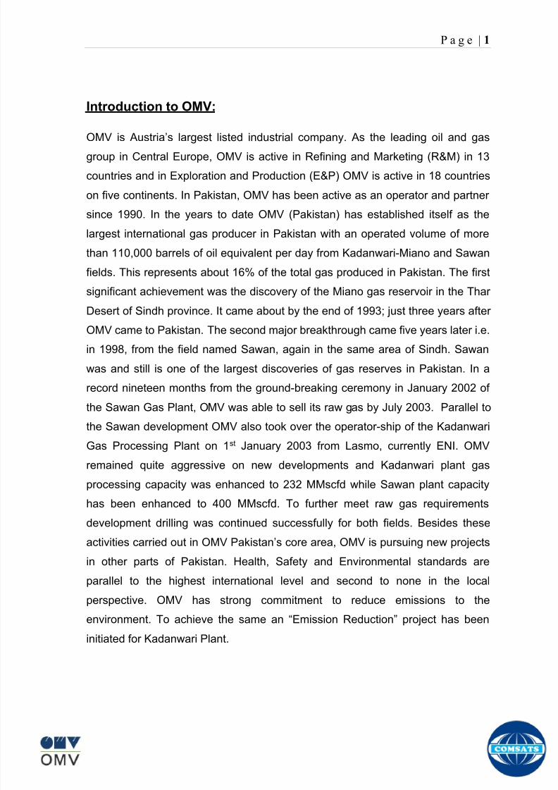
8102019 Gas sweetening Plant
httpslidepdfcomreaderfullgas-sweetening-plant 562
P a g e | 1
Introduction to OMV
OMV is Austriarsquos lar gest listed industrial company As the leading oil and gas
group in Central Europe OMV is active in Refining and Marketing (RampM) in 13
countries and in Exploration and Production (EampP) OMV is active in 18 countries
on five continents In Pakistan OMV has been active as an operator and partner
since 1990 In the years to date OMV (Pakistan) has established itself as the
largest international gas producer in Pakistan with an operated volume of more
than 110000 barrels of oil equivalent per day from Kadanwari-Miano and Sawan
fields This represents about 16 of the total gas produced in Pakistan The firstsignificant achievement was the discovery of the Miano gas reservoir in the Thar
Desert of Sindh province It came about by the end of 1993 just three years after
OMV came to Pakistan The second major breakthrough came five years later ie
in 1998 from the field named Sawan again in the same area of Sindh Sawan
was and still is one of the largest discoveries of gas reserves in Pakistan In a
record nineteen months from the ground-breaking ceremony in January 2002 of
the Sawan Gas Plant OMV was able to sell its raw gas by July 2003 Parallel to
the Sawan development OMV also took over the operator-ship of the Kadanwari
Gas Processing Plant on 1st January 2003 from Lasmo currently ENI OMV
remained quite aggressive on new developments and Kadanwari plant gas
processing capacity was enhanced to 232 MMscfd while Sawan plant capacity
has been enhanced to 400 MMscfd To further meet raw gas requirements
development drilling was continued successfully for both fields Besides these
activities carried out in OMV Pakistanrsquos core area OMV is pursuing new projects
in other parts of Pakistan Health Safety and Environmental standards are
parallel to the highest international level and second to none in the local
perspective OMV has strong commitment to reduce emissions to the
environment To achieve the same an ldquoEmission Reductionrdquo project has been
initiated for Kadanwari Plant
8102019 Gas sweetening Plant
httpslidepdfcomreaderfullgas-sweetening-plant 662
P a g e | 2
Scope of Plant
Carbon dioxide and hydrogen sulfide which fall into the category of acid gasesare commonly found in natural gas streams at levels as high as 80 In
combination with water they are highly corrosive and can rapidly destroy
pipelines and equipment unless they are partially removed or exotic and
expensive materials of construction are used Hydrogen sulfide is toxic and at
relatively modest levels can be life threatening Carbon dioxide also reduces the
heating value of a natural gas stream and wastes pipeline capacity In LNG
plants CO2 must be removed to prevent freezing in the low-temperature chillers
Therefore the composition of gas is adjusted as per limits prescribed by SNGPL
(Sui Southern Gas Pakistan Limited) and is sold to the government The gas is
injected to the SNGPL main facility at a pressure of 1100 psi
The sales gas specifications are as follows
CO2 Maximum = 3
H2S Maximum = 38 ppm
CV Minimum = 920 BtuscfWater = 7lbMMscf
OMV Kadanwai facility sale gas composition
8102019 Gas sweetening Plant
httpslidepdfcomreaderfullgas-sweetening-plant 762
P a g e | 3
OMV Kadanwai facility feed gas composition
Process Description
Gas from Kadanwari High pressure wells is routed to Kadanwari High Pressure
slug catcher Gas from Kadanwari low pressure wells is routed to Kadanwari low
pressure slug catcher and is fed to 2 stage Front End Compressor (FEC) to
increase the pressure up to production pressure Gas from FEC is fed to high
pressure stream flowing into Kadanwari High Pressure slug catcher The gas
from Miano wells is fed to Miano Slug Catcher
Kadanwari and Miano gas streams after separately metered are fed to a common
header which splits into two identical skids A and B Here we will discuss one
skid in common Each skid is routed to fin fan coolers where it is cooled and fed
to Inlet separator where water and heavy hydrocarbons are removed from feed
gas The condensate from all units is sent to produce water system
8102019 Gas sweetening Plant
httpslidepdfcomreaderfullgas-sweetening-plant 862
P a g e | 4
The gas then passes through pretreatment skid which consists of following units
Feed Cooler
Feed Gas Scrubber
Filter Coalescer
Feed Gas Heater
Activated Carbon Guard Filter
Particle Filter
Its main function is to remove contaminants from gas such as dust lube oils
heavy hydrocarbons etc which may poison or reduce efficiency of membrane
unit
After pretreatment gas is fed to Molecular Sieve Absorbers (Memguard Units)
which ensures gas supplied to membranes is up to membrane standards of UOP
(vendor of membrane system) It removes all moisture and heavy hydrocarbons
from gas stream
Pretreated gas is now fed to the primary membranes The permeate stream (rich
in CO2) is sent to recycle membranes after passing through recycle compressor
and recycle pretreatment The permeate stream of recycle membranes is used as
regenerative medium for Memguard units and rest is sent to incinerator and
burnt The residual gas (rich in CH4) from primary membrane and recycle
membranes (all skids) is sent to H2S polishers via a common header
H2S polisher unit reduce the hydrogen sulfide level to the sales limit The gas is
now metered after compressing in sales gas compressor and is sent to SNGPL
trunk line after metering
Water is remove from condensate at produced water system by a three phase
separator The condensate is sold to refinery Major quantity is exported to
various industries
8102019 Gas sweetening Plant
httpslidepdfcomreaderfullgas-sweetening-plant 962
P a g e | 5
Figure Overall plant Process Flow Diagram
8102019 Gas sweetening Plant
httpslidepdfcomreaderfullgas-sweetening-plant 1062
P a g e | 6
Wellhead
A wellhead is the component at the surface of an oil or gas well that provides the
structural and pressure-containing interface for the drilling and production
equipment Its function is to maintain surface control of the well It forms a seal to
prevent well fluids from leaking or blowing at the surface They are rated for
working pressure of 2000 psi to 15000 psi (or greater)
When the well has been drilled and it is ready to provide an interface with the
reservoir rock and a tubular channel for the well fluids The surface pressure
control is provided by a Christmas tree which is installed on top of the wellhead
with valves and choke equipment to control the flow of well fluids during
production
Christmas tree
A Christmas tree is an assembly of valves spools and fittings used for an oil
well gas well water injection well gas injection well condensate well and other
types of wells
The primary function of a tree is to control the flow usually oil or gas out of the
well When the well and facilities are ready to produce and receive oil or gas tree
valves are opened and the formation fluids are allowed to go through a flow line
This leads to a processing facility A tree often provides numerous additional
functions including chemical injection points well intervention means pressure
relief means monitoring points (such as pressure temperature corrosion
erosion sand detection flow rate flow composition valve and choke position
feedback) and connection points for devices such as down hole pressure andtemperature transducers (DHPT) On producing wells chemicals or alcohols or
oil distillates may be injected to preclude production problems (such as
blockages)
The control system attached to the tree controls the down-hole safety valve
(SCSSV) while the tree acts as an attachment and means of the control system
to the down-hole safety valve
8102019 Gas sweetening Plant
httpslidepdfcomreaderfullgas-sweetening-plant 1162
P a g e | 7
Figure 1
Well Head and Christmas Tree
8102019 Gas sweetening Plant
httpslidepdfcomreaderfullgas-sweetening-plant 1262
P a g e | 8
Master Valves
The two lower valves are called the master valves Master valves are normally in
the fully open position and are never opened or closed when the well is flowing
(except in an emergency) to prevent erosion of the valve sealing surfaces They
are gate type valves
1 Lower Master Valve (LMV)
2 Upper Master Valve (UMV)
The lower master valve will normally be manually operated while the upper
master valve is often hydraulically actuated allowing it to be used as a means of
remotely shutting in the well in the event of emergency
Wing Valve
A wing valve is normally used to shut in the well when flowing thus preserving
the master valves for positive shut off for maintenance purposes The wing
valve can be a gate valve or ball valve Hydraulic operated wing valves are
usually built to be fail safe closed meaning they require active hydraulic pressure
to stay open This feature means that if control fluid fails the well will
automatically shut itself in without operator action
In Kadanwari well sites there is only one manually operated wing valve On the
other hand at Miano well sites there are two wing valves one being operated
manually and other hydraulically
Production Wing Valve
The right hand valve is often called the flow wing valve or the production wing
valve because it provides flow path for hydrocarbons to production facility
Kill wing valve
The left hand valve is often called the kill wing valve It is primarily used for
injection of fluids such as corrosion inhibitors or methanol to prevent hydrate
formation It is typically manually operated It can kill the well temporarily be
injection brine solution which provides a pressure head to well and temporarily
8102019 Gas sweetening Plant
httpslidepdfcomreaderfullgas-sweetening-plant 1362
P a g e | 9
suspends it for maintenance of well head Also it is used to permanently kill the
well A chemical is injected down the well that seals the piping down the well and
kills the well permanently
Swab valve
The swab valve is used to gain access to the well for wire line operations
intervention and other work over procedure On top of it is a tree adapter
and cap that will mate with various equipment For such operations a
lubricator is assembled up onto the top of the tree and the wire or coil is lowered
through the lubricator through swab valve and into the well This valve is typically
manually operated
Choke
A choke holds back pressure by restricting the flow opening at the well head This
is done to make better use of the gas for natural gas lift and to control the bottom-
hole pressure for recovery reasons
CHECK VALVE
The check is introduced in production flow line to prevent any reverse flow from
the line into the well It has a hinged flap which lifts to permit normal flow but
closes to prevent reverse flow
TOP ADAPTOR
The top adaptor is a fitting on top of the swab valve with a threaded connection
During normal well operations a pressure gauge is fitted to monitor flowing and
shut in wellhead pressures However during well service operations the cap can
be removed to allow installation of lubricators for wire-line operations
SCSSSV (Surface Control Sub Surface Safety Valve)
A subsurface safety valve is essentially a shutdown valve installed at the upper
wellbore for emergency shutdown to protect the production tubing and wellhead
in case of overpressure Subsurface safety valves can offer a barrier against flow
in the event of a wellhead collapse or other disastrous event Purpose of asubsurface safety valve (SSSV) is to avoid the ultimate disaster which can result
8102019 Gas sweetening Plant
httpslidepdfcomreaderfullgas-sweetening-plant 1462
P a g e | 10
in release of reservoir fluids to the surroundings This makes SSSV a very
important component of a well completion
A subsurface safety valve is typically a uni-directional flapper valve directed in
such a way that the flappers open downwards when pressure is applied from an
upward direction The flapper can only open in the downward direction So even if
high pressure is applied by the well fluids from a
downward direction a safety valve can remain
closed This makes a subsurface safety valve fail-
safe To open the valve hydraulic signal is sent from
the surface well control panel This hydraulic
pressure is responsible for keeping the flappers of
SSSV open and loss of hydraulic pressure result in
closing of the valve Thus wellbore can be isolated in
case of system failure or damage to the surface
facilities
Types of Christmas tree
There are two types of Christmas Tree
1 Solid block
2 Conventional
The solid block Christmas Tree has a central solid unit holding several valves
in a pre-constructed block Their advantage is the reduction in potential leak
paths and their higher pressure rating (Fig 2)
The conventional Christmas Tree is built up from individual valves bolted
together to form an assembly (Fig 3)
8102019 Gas sweetening Plant
httpslidepdfcomreaderfullgas-sweetening-plant 1562
P a g e | 11
Figure 2
Figure 3
8102019 Gas sweetening Plant
httpslidepdfcomreaderfullgas-sweetening-plant 1662
P a g e | 12
Wellhead Control Panel
Wellhead control panel is key equipment in oil amp gas industry to protect oilfield
facilities and environment from emergency incidents such as wellhead fire which
is one of main control systems to ensure oilfield oil production and transportation
to be safely operation according to international standards and national
regulation Wellhead control panel is composed of hydraulic power unit tubing amp
fitting and instrument valve and electrical control devices Hydraulic power unit
supply hydraulic resource to open and close safety valves including master
valves wing valves and SCSSSV
Its performs
Local OnOff SSV
Remote control SSV through RTU( remote terminal unit)
High-Low pressure sense shut-down automatically
Fusible Plug Anti-fire Shut-down automatically
Function of showing system pressure
Relief Valve shall be installed on each hydraulic circuit to prevent high
pressure
Function of showing hydraulic level and level switch for alarm
Function of defending pressure impact of system
Function of system pressure monitoring (by pressure transmitter of control
panel)
Function of remote emergency shut-down (by magnetic valve of control
panel)
Function of OnOff SSV monitoring (by pressure switch of control loop of
control panel)
8102019 Gas sweetening Plant
httpslidepdfcomreaderfullgas-sweetening-plant 1762
P a g e | 13
Chemical Injection
Chemical injection systems are commonly used in production facilities to prevent
or eliminate a wide range of problems that might negatively affect the production
flow It is done for flow assurance protection of process equipment such as
pipelines or to optimize processes in production facilities
Typical flow assurance chemicals are
Wax inhibitors
Pour point depressants
Asphaltene inhibitors
Corrosion inhibitors
A corrosion inhibitor is a chemical compound that is added to liquid or gas to
decreases the corrosion rate of a material typically a metal or an alloy The
effectiveness of a corrosion inhibitor depends on fluid composition quantity of
water and flow regime Its common mechanism involves formation of a coating
8102019 Gas sweetening Plant
httpslidepdfcomreaderfullgas-sweetening-plant 1862
P a g e | 14
which prevents access of the corrosive substance to the metal The corrosive
agents are generally oxygen hydrogen sulfide and carbon dioxide
At our production site the major risk is corrosion of piping and equipment The
maximum allowable corrosion rate is approximately 02 mm per year and
corrosion rate without inhibitor could be approximately 11 mm per year so the
corrosion protection program is designed to achieve a target corrosion rate of
less than 01 mm per year which is achieved by an inhibitor system efficiency of
99 Inhibitor is injected into the well stream flow through an atomizing nozzle
located downstream of the respective wellhead coolers at the duplexcarbon steel
interface In normal operation as per NALCO standards chemical (brand name
EC1144B) at rate of frac12 Liter per MMSCFD of gas is being injected into the flow
line of miano15 flow lines made of carbon steel Moreover the composition can
vary depending upon the composition of well fluids and material of pipeline This
method of injection ensures even distribution of the chemical on the interior
surface of the pipeline The individual well sites are equipped with Chemical
Injection Packages comprising of a stainless steel storage tank and two
pneumatic motor driven pumps in parallel Instrument gas is used to drive the
pumps Normally one pump is running with the other standby
Water Conning
Water coning is a term used to describe the mechanism underlying the upward
movement of water into the perforations of a producing well Coning can seriously
impact the well productivity and influence the degree of depletion and the overall
recovery efficiency of the reservoir The specific problems of water coning are
listed below
Costly added water handling
Gas production from the original or secondary gas cap reduces pressure
Reduced efficiency of the depletion mechanism
The water is often corrosive and its disposal costly
The affected well may be abandoned early
Loss of the total field overall recovery
8102019 Gas sweetening Plant
httpslidepdfcomreaderfullgas-sweetening-plant 1962
P a g e | 15
Therefore conning has an important influence on operations recovery and
economics The phenomena is shown in picture below
Corrosion
Corrosion is referred as chemical deterioration of a metal Commonly this
means loss of electrons of metals reacting with water and oxygen
Weakening of iron due to oxidation of the iron atoms is a well-known
example of electrochemical corrosion This is commonly known as
rust Most structural alloys corrode merely from exposure to moisture
in the air but the process can be strongly affected by exposure to
certain substances Corrosion can be concentrated locally to form a pit
or crack or it can extend across a wide area to produce general
deterioration (uniform corrosion)
The following reaction takes place at the active sites
2Fe =gt 2Fe++ + 4e-
The free electrons travel through the metal path to the less active sites where
the following reaction takes place
O2 + 4e- + 2H20 =gt 4 OH-
8102019 Gas sweetening Plant
httpslidepdfcomreaderfullgas-sweetening-plant 2062
P a g e | 16
Recombination of these ions at the active surface produce the following
reaction which yields the iron-corrosion product ferrous hydroxide
2Fe + O2 + 2H2O =gt 2Fe (OH) 2
CORROSION PROTECTION SYSTEM
Coatings and painting
Painting and the application of enamel bitumen and PVC
coating are the most common anti-corrosion treatments They
work by providing a barrier of corrosion-resistant material
between the damaging environment and the structural material
Corrosion Inhibitors
Corrosion inhibitor is injected into the flow lines as mentioned in
detail on page 8
Cathodic Protection
Cathodic Protection (CP) is a technique used to control the corrosion of a
metal surface by making it the cathode of an electrochemical cell It
converts all of the anodic (active) sites on the metal surface to cathodic
(passive) sites by supplying electrical current (or free electrons) from an
alternate source It is accomplished in two ways
a) A simple method of protection connects protected metal to a more easily
corroded sacrificial metal to act as the anode The sacrificial metal then
corrodes instead of the protected metal The process is similar to a simple
DC cell in which the more active metal becomes the anode and corrodes
whereas the less active metal becomes the cathode and is protected
b) For larger structures galvanic anodes cannot economically deliver enough
current to provide protection Therefore impressed current cathodic
protection (ICCP) systems are used These consist of anodes connected
to a DC power source In remote areas power sources such as solar
panels may be used The output DC negative terminal is connected to the
8102019 Gas sweetening Plant
httpslidepdfcomreaderfullgas-sweetening-plant 2162
8102019 Gas sweetening Plant
httpslidepdfcomreaderfullgas-sweetening-plant 2262
P a g e | 18
frequently to limit liquid holdup and minimize the slug volumes of liquid which can
be generated by the system
Coating
Pigs may be used to apply internal pipe coatings such as epoxy coating
materials in operating pipelines Pigs may also be used with corrosion inhibitors
to distribute and coat the entire internal wetted perimeter
Inspection
Pigs are being used more frequently as inspection tools Gauging or sizing pigs
are typically run following the completion of new construction or line repair to
determine if there are any internal obstacles bends or buckles in the pipe Pigs
can also be equipped with cameras to allow viewing of the pipe internals
Electronic intelligent or smart ldquopigsrdquo that use magnetic and ultrasonic systems
have been developed and refined that locate and measure internal and external
corrosion pitting dents buckles and any other anomalies in the pipe wall
Intelligent pigs
The accuracy of location and measurement of anomalies by the intelligent pigs
has continued to improve Initially the electronics and power systems were so
large that intelligent pigs could be used only in lines 30 in and greater in size
The continued sophistication and miniaturization of the electronic systems used
in the intelligent pigs has allowed the development of smaller pigs that can be
used in small-diameter pipelines Newly enacted DOT pipeline-integrity
regulations and rules acknowledge the effectiveness of the intelligent pigs and
incorporate their use in the pipeline-integrity testing process
Compressors
A gas compressor is a mechanical device that increases the pressure of a gas by
reducing its volume Gas pressure is increased by forcing gas molecules together
to reduce gas volume When volume is reduced gas pressure increases
All gases have large spaces among their molecules These spaces could be
enhanced further and decreased by doing some work Work done which is used
8102019 Gas sweetening Plant
httpslidepdfcomreaderfullgas-sweetening-plant 2362
P a g e | 19
for the enhancement of these spaces is called expansion and work done to
minimize these spaces is called compression All gases while expansion
produces cooling effect and while compression of gases raises there
temperature Compression is a term used to force gases to occupy smaller
volumes by increasing their pressure Volume of gases is interlinked with
temperature and pressure of the gas which is cleared by 2 laws govern gas
compressions
Boyles Law
Charles Law
The main types of compressor are listed below
Front End Compressor
The plant currently processes gas from a number of wells The flow and pressure
from some of these wells (currently K-10 K-11 amp K-12) has declined and they
cannot be fed directly into the Central Processing Facility To recover the
maximum gas reserves from these wells a Front End Compressor is employed
The compressor is a two stage double acting gas engine driven reciprocating
(PT) compressor Double acting means that gas is compressed on each end of
the piston It normal operates with a speed range of 600 to 900 RPM and isequipped with four compressor cylinders two for each stage Each cylinder is
8102019 Gas sweetening Plant
httpslidepdfcomreaderfullgas-sweetening-plant 2462
P a g e | 20
also equipped with a variable volume head end pocket
In case of compressor emergency shutdown the production chokes and the
Upper Master Valves on the on line wells will close and operator will be notified in
central control room Sweet gas from gas distribution network is used to operate the
gas engine driver of the compressor package The detailed scheme of working is
shown in figure (page 22 )
PT Reciprocating Compressor
The mechanical cycle of piston tube reciprocating compressor comprises four
strokes the expansion stroke the intake stroke the compression stroke and the
discharge stroke
Expansion Stroke
As the piston moves back on the expansion stroke the chamber volume
increases and the pressure drop As the pressure drops the discharge valve
closes since there is greater pressure in the discharge line than in the chamber
Intake Stroke
As the piston moves back during the intake stroke the pressure decreases until it
is less than the pressure in the inlet line This higher intake pressure opens the
inlet valve and gas rushes into the cylinder equalizing the pressure there with
the intake pressure The compression chamber is now at or near the intake
pressure
Compression Stroke
The piston now starts the compression stroke by moving forward decreasing the
chamber volume and increasing the pressure The increased pressure is now
higher than the intake pressure causing the intake valve to close
Discharge Stroke
The piston continues to move to the left during the discharge stroke This creates
an increase in chamber pressure until it is greater than the discharge pressure
When this happens the Discharge valve opens and the compressed air from the
8102019 Gas sweetening Plant
httpslidepdfcomreaderfullgas-sweetening-plant 2562
P a g e | 21
cylinder goes into the discharge line The compression cycle is then repeated
from the stage
Compressor Capacity
The capacity of the compressor depends upon cylinder displacement That
displacement is simply the volume that the piston displaces (moves) as it travels
from one end of the cylinder to the other Capacity and displacement is equal to
the cross-sectional area of the cylinder times the length of the stroke
Lubrication and Cooling
Lubricating oil is circulated through the system by a gear pump which is chain
driven from the engine crank shaft The oil pump is mounted on the engine front
housing
The pump operates between 30 - 40 psig
8102019 Gas sweetening Plant
httpslidepdfcomreaderfullgas-sweetening-plant 2662
P a g e | 22
A circulating pump deliver cooling water to the water jackets in the cylinder block
flowing around the cylinder liners and is directed into the cylinder heads Each
cylinder head has water cooled exhaust elbows which outlet the water into the
water cooled exhausts From the end of engine the water flows to compressor
1st and 2nd stage cylinders and compressor lube oil cooler (LOwater heat
exchanger) The water from the compressor cylinder and lube oil cooler returns
to engine water cooled exhaust
Figure Flow diagram of Front End Compressor
8102019 Gas sweetening Plant
httpslidepdfcomreaderfullgas-sweetening-plant 2762
P a g e | 23
Centrifugal Compressor
Centrifugal compressors are machines in which velocity and pressure given to air
or gas in a radial direction by one or more impellers diffuser combination In a
centrifugal compressor the mechanical energy is increased by centrifugal action
The gas enters the suction eye of a high speed rotary element called the impeller
which carries radial vanes integrally cast in it As the impeller rotates the blades
of the impeller force the gas outward from the center the impeller to the outer rim
of impeller the increase in velocity of the gas creates a flow pressure area at the
eye of the impeller The gas at the outer rim of the impeller is forced in to a
passage way called a diffuser where the velocity decreases in the pressure of the
gas
Inlet
The inlet to a centrifugal compressor is typically a simple pipe It may include
features such as a valve and both pressure and temperature instrumentation
Centrifugal impeller
The key component that makes a compressor centrifugal is the centrifugal
impeller shown above It is the impellers rotating set of vanes (or blades) that
gradually raises the energy of the working gas This is identical to an axial
compressor with the exception that the gases can reach higher velocities and
energy levels through the impellers increasing radius
8102019 Gas sweetening Plant
httpslidepdfcomreaderfullgas-sweetening-plant 2862
P a g e | 24
Diffuser
The next key component to the simple centrifugal compressor is the diffuser
Downstream of the impeller in the flow path it is the diffusers responsibility to
convert the kinetic energy (high velocity) of the gas into pressure by gradually
slowing (diffusing) the gas velocity
SEPERATORS
A well-stream is a mixture of gases hydrocarbon liquids water solids and
contaminants Due to variations in pressure and temperature gases evolve from
the liquids water vapor condenses and some of the well-stream changes to liquid
and free gas The separation of well-stream fluids takes place in a separator This
pressure vessel is manufactured in three forms
1 horizontal
2 vertical
3 spherical
To help separation the vessel is normally designed with a series of internal
fittings These fittings are built into the separator to ensure total phase separation
of the well-stream
In gas plants separators are given alternative names due to the function they
perform in the process system A scrubber does a similar job to a knockout drum
However the scrubber usually separates a stream containing high gas-to-liquid
ratios The knockout drum is used where a high degree of liquids are entrained in
the gas
Fluid flow from a well can include gas condensable liquid vapors water water
vapor crude oil and solids As well-stream fluids reach ground level where
pressure is lower than in the reservoir the capacity of the liquid to hold gas in
solution decreases and gas separates out of the oil
Separation depends upon the effect of gravity to separate liquids For adequate
separation one fluid must be lighter than the other fluid For example distillates
8102019 Gas sweetening Plant
httpslidepdfcomreaderfullgas-sweetening-plant 2962
P a g e | 25
(gasoline kerosene etc) and crude oil will not separate in a vessel because they
tend to dissolve in each other Because a separator basically depends upon
gravity to separate the fluids the ease with which separation takes place
depends upon the difference in density of the fluids
Droplets of liquid will separate from gas provided
a) The gas remains in the separator long enough
b) The gas flow remains constant to provoke separation
The difference in density between a gas and liquid will therefore determine the
maximum flow rate of liquid in the vessel
Figure Two phase horizontal separator
Gas bubbles in the liquid will break out in some oil field applications in 30 to 60
seconds Consequently the separator is designed so that the liquid remains in
the vessel for 30 to 60 seconds The length of time that a liquid remains in the
vessel is called its residence time Residence time differs widely from field to field
depending upon viscosity and API Gravity
Another important factor which must be considered is temperature Generally a
decrease in operating temperature will increase the liquid recovery in a separator
8102019 Gas sweetening Plant
httpslidepdfcomreaderfullgas-sweetening-plant 3062
P a g e | 26
as the gas condenses By reducing the pressure on the fluid flash separation
occurs resulting in a flow through the separator which is controlled by external
instrumentation
COALESCENCE
Another important principle in fluid separation is that of coalescence This means
the coming together of liquid droplets created by the force of gravity
A common example of coalescing occurs when drops of water form on the
windshield of a car as it is driven in fog As the tiny drops or water which make up
the fog strike the windshield they combine and eventually form a drop large
enough to run down the glass
Several of the internal devices of a separator such as deflector plates
straightening vanes and even the vessel walls are forms of coalescers In each
vessel drops of liquid adhere to the surface of the device and combine with other
8102019 Gas sweetening Plant
httpslidepdfcomreaderfullgas-sweetening-plant 3162
P a g e | 27
drops until the drop is large enough to fall out The effectiveness of separation
will also depend upon the total amount of coalescing surface area that is present
There are many different types of separators used in the Oil amp Gas industry
Consequently separators are manufactured with one two or several internal
fittings depending on their use and quick removal of these fluids from the vessel
DEFLECTOR PLATES
These are fitted in front of the inlet to the separator and can be net or
dish-shaped Their purpose is to absorb the impact of the incoming fluids and to
encourage the separation of gas and liquids They also slow the flow rate of the
liquids through the vessel
WEIRS
A weir is a metal wall which is fitted across the inside of the vessel normally to a
height of 50 of the overall height of the separator Its purpose is to assist the
process of three phase separation The inlet fluids (oil plus water) are given time
to separate in the liquid accumulation section The water level (interface) is
normally controlled at 50 of the height of the weir Oil floating on the wateroverflows the weir and accumulates in the small oil compartment where it is
drawn off under level control
CENTRIFUGAL DEVICES
These are used in both vertical and horizontal separators for gas-liquid
separation The device imparts a swirling motion to the fluids entering the vessel
Centrifugal force causes the heavier liquids to travel outwards towards the walls
of the vessel and the lighter gases to flow up the centre Centrifugal devices are
also known as cyclones
VORTEX BREAKERS
When liquid flows through a drain outlet a vortex (whirlpool) will form This can
be seen when we pull the plug from a sink or bath tub The same would happen
as water and oil flow from the separator This condition a vortex could allow gas
to flow down the centre of the whirlpool and enter the liquid phase causing
8102019 Gas sweetening Plant
httpslidepdfcomreaderfullgas-sweetening-plant 3262
P a g e | 28
pressurizing of tanks etc To stop this happening vortex breakers are fitted to all
liquid outlets Although they come in a number of different designs vortex
breakers all serve the same purpose - to prevent a whirlpool from forming
MIST OR DEMISTER PADS
The gas which is released from the fluids in the separator still contains droplets of
oil and water which coalesce and fall when the drops get large enough The
demister pad assists in this process Made from knitted wire and contained within
a sturdy frame it causes the gas to continually change its direction of flow
Because gas changes direction far easier than liquid the gas will flow around
each strand of wire whilst the liquid entrained in the gas stream will continue and
stick to the wire
COALESCING PLATES
There are several different forms of coalescing devices the most common of
which are coalescing plates These plates are mounted in the flow stream of the
fluids and assist in breaking down oil-water emulsions The fluid is forced to
follow a path that constantly changes direction This causes the water droplets to
gather together or coalesce and fall to the bottom of the separator The same
principle is used to separate gas and oil mixtures when the oil droplets are
induced to coalesce Simply stated every surface within the separator including
the separator walls assists with the coalescing process
STRAIGHTENlNG VANES
These are often fitted to horizontal separators to remove turbulence in the gas
stream after initial separation at the inlet deflector
FLOAT SHEILD
Internal floats are used as level controllers Any agitation of the liquid surface or
the effect of coalesced liquids falling on the float may cause control problems
Therefore a float shield is fitted to enclose the float creating an area of still liquid
8102019 Gas sweetening Plant
httpslidepdfcomreaderfullgas-sweetening-plant 3362
P a g e | 29
MEMBRANES
The gas contains 12 carbon dioxide and 22 ppm of hydrogen sulphide at 115oF
and 1100 psig This needs to be removed before the gas can be exported The
majority of carbon dioxide hydrogen sulphide and water is removed by means of
membranes
Membranes are thin semipermeable barriers that selectively separate some
compounds from others Currently the only commercially workable membranes
used for CO2 removal are polymer based for example cellulose acetate
polyimides polyamides polysulfone polycarbonates and polyetherimide The
membrane does not operate as a filter where small molecules are separated
from larger ones through a medium with pores rather it separates based on how
well different compounds dissolve into the membrane and diffuse through it The
membranes are manufactured in flat sheets consisting of an extremely thin
nonporous layer mounted on a much-thicker and highly porous layer of the same
material providing mechanical strength The flat sheets are combined into a
spiral-wound element (Figure below) Feed gas enters along the side of the
membrane and passes through the feed spacers As the gas travels between
membrane sheets CO2 H2S and H2O permeate through the membrane and are
collected in the permeate tube The driving force for transport is the high-feed
pressure and low-permeate pressures The gas on the feed side that does not
permeate leaves through the side of the element opposite the feed position Once
the membranes have been manufactured into elements six to 12 elements are
joined together and inserted into a tube Multiple tubes are mounted on skids in a
horizontal orientation
8102019 Gas sweetening Plant
httpslidepdfcomreaderfullgas-sweetening-plant 3462
P a g e | 30
Figure Membrane general Working
In high H2S applications most polymers have been shown to have very little
resistance to H2S plasticization (ldquosofteningrdquo of the membrane) and as a
consequence can only be used at very low H2S partial pressure limits Cellulose
acetate membranes in contrast have been shown to be applicable at extreme
H2S partial pressure conditions It is these membranes that have been utilized in
the testing to determine the limits of membrane performance in high H 2S
applications
The primary membranes used in Kadanwari facility are Cellulose acetate
Cellulose acetic acid and acetic anhydride are mixed together and reacted to
form cellulose acetate polymers This process is aided by the addition of a small
amount of sulfuric acid which is subsequently neutralized during processing
However the membranes are bought from UOP (vendor) and installed for use
8102019 Gas sweetening Plant
httpslidepdfcomreaderfullgas-sweetening-plant 3562
P a g e | 31
How membrane work
The basic principle of separation is selectivity of certain components of a mixture
for the membrane For example the cellulose acetate membrane has very high
selectivity for CO2 and H2S as compared to CH4 Therefore such type of
membrane can be used in gas sweetening process
The selectivity is directly related to the Permeability of gas which accounts that
which gas can pass across the membrane more easily In simple words
membranes being polymer materials are made of long chains of molecules The
different structure of polymer materials only allow selective molecules to pass
through them depending upon chemical and physical compatibility Thus
permeability depends upon choice of polymer
The permeability is determined by permeability coefficient (P) and is product of
solubility (S) and diffusivity (D)
P = S D
Solubility
The solubility is mainly determined by ease of condensation Heavy molecules
are more readily condensed Therefore higher molecular weighted molecules will
more easily condensed and therefore have greater solubility
Molecule Molecular weight
CH4 16
H2S 34
CO2 44
8102019 Gas sweetening Plant
httpslidepdfcomreaderfullgas-sweetening-plant 3662
P a g e | 32
Diffusivity
Diffusivity is ease of molecule to penetrate into some material It depends on size
of gas molecule Here size of molecule is not to be confused by molecular weight
it is the size of the structure Eg the size of O2 molecule is smaller than N2
Molecule Molecular Diameter (Ao)
CO2 33
H2S 36
Ch4 40
For cellulose acetate
DCO2DCH4 S CO2S CH4 P CO2P CH4
45 73 308
Chemical degradation
Cellulose acetate polymer is chemically degraded by a process called hydrolysis
which means breaking apart by the addition of water This is a chemical reaction
in which water is added to the cellulose acetate polymer causing the release of
acetic acid molecules This process proceeds stepwise until all the acetate
groups are released resulting in the reformation of cellulose Moreover alcohols
aromatic hydrocarbons or solvents with chlorine nitro benzene or similar
aromatic solvents will harm the membrane It will expand and lose plastification in
contact with them
Effect of Temperature
The permeation rates of all gases increases with increasing temperature
however membrane selectivity for CO2 over hydrocarbon decreases at higher
8102019 Gas sweetening Plant
httpslidepdfcomreaderfullgas-sweetening-plant 3762
P a g e | 33
temperature Consequently CO2 removal will improve as operating temperature
increases but hydro carbon recovery will decrease
Primary Membrane
The primary membranes comprise of two trains Each train consists of two
sections AB and CD each section consists of a 30 tube membrane skid (A and
C) followed by a 25 tube skid (B and D) The conditioned gas (after pre-
treatment) enters the primary membrane via the particulate filter adjacent to the
skid The gas is fed to the membranes through a common inlet manifold which
supplies primary membranes skids A and C A pressure control loop located
upstream of the manual inlet isolation valve is provided to maintain a constant
supply pressure to the membrane skid and to allow for preheating at the inlet
prior to skid start-up This pressure control loop can also be used during start-up
to control the pressurization of the pretreatment skid and associated pipes to the
primary membranes
The gas passes through membrane skid A the residual gas exiting the membrane
skid is sent to skid B and the permeate to common permeate discharge header An
identical arrangement is provide on the inlet to skid C as provided on skid A Theresidual gas from skid B combines with the residual gas from skid D in a common
discharge header and is then sent to the H2S polishing towers via the feed coolers
on the pre-treatment skid The permeate from skid B is sent to the common
permeate discharge header The permeate discharge header sends the gas to
either the recycle compressor or the vent header via a pressure control loop
Overpressure protection for the membranes is provided by a pressure safety valve
on the supply header to the membrane banks
8102019 Gas sweetening Plant
httpslidepdfcomreaderfullgas-sweetening-plant 3862
P a g e | 34
Secondary (Recycle) Membrane
The recycle membranes comprise of a single train with two skids each with four
banks of membrane tubes The conditioned gas from the discharge of the recycle
pre-treatment skid is routed to the first recycle membrane skid The gas passes
through the membranes the residual gas is fed to primary membrane (skid A) inlet
via feed gas cooler and permeate to the common permeate discharge header An
identical arrangement is provide on the inlet to skid B Permeate from the recycle
membrane skids A and B is routed to the vent header Some portion of permeate is
heated and sent for regeneration in Mem-Guard units Nitrogen purge can be
connected downstream of the inlet isolation valve on each skid to enable the
membrane tubes to be purged and left pressurized during prolonged shutdown
8102019 Gas sweetening Plant
httpslidepdfcomreaderfullgas-sweetening-plant 3962
P a g e | 35
Figure Flow Diagram of Recycle membrane unit
8102019 Gas sweetening Plant
httpslidepdfcomreaderfullgas-sweetening-plant 4062
P a g e | 36
ADVANTAGES OF MEMBRANE SYSTEMS
Membrane systems have major advantages over more-traditional methods of
acid gas removal
Lower capital cost Membrane systems are skid mounted and so the
scope cost and time taken for site preparation are minimal Installation
costs are significantly lower than alternative technologies especially for
remote areas Furthermore no additional facilities for solvent storage and
water treatment needed by other processes are required
Lower operating costs The only major operating cost for single-stage
membrane systems is membrane replacement This cost is significantly
lower than the solvent replacement and energy costs associated with
traditional technologies The improvements in membrane and
pretreatment design allow a longer useful membrane life which further
reduces operating costs The energy costs of multistage systems with
large recycle compressors are usually comparable to those for traditionaltechnologies
Deferred capital investment Often contracted sales-gas flow rates
increase over time as more wells are brought on-line With traditional
technologies the system design needs to take this later production into
account immediately and so the majority of the equipment is installed
before it is even needed The modular nature of membrane systems
means that only the membranes that are needed at start-up need be
installed The rest can be added either into existing tubes or in new skids
only when they are required
Operational simplicity and high reliability Because single-stage
membrane systems have no moving parts they have almost no
8102019 Gas sweetening Plant
httpslidepdfcomreaderfullgas-sweetening-plant 4162
P a g e | 37
unscheduled downtime and are extremely simple to operate They can
operate unattended for long periods of time The addition of a recycle
compressor adds some complexity to the system but still much less than
with a solvent- or adsorbent-based technology Multistage systems can be
operated at full capacity as single-stage systems when the recycle
compressor is down
Good weight and space efficiency Skid construction can be optimized
to the space available This space efficiency is especially important for
offshore environments where deck area is at a premium and is the
reason why so many new offshore developments have chosen to use
membranes for acid gas removal Figure 6 illustrates the space efficiency
of membrane systems The membrane unit in the lower left corner
replaced all the amine and glycol plant equipment shown in the rest of the
picture
Adaptability Because membrane area is dictated by the percentage of
acid gas removal rather than absolute acid gas removal small variations
in feed acid gas content hardly change the sales-gas acid gas
specification For example a system designed for 10 down to 3 acid
gas removal produces a 35 product from a 12 feed gas and a 5
product from a 15 feed gas
Design efficiency The membrane and pretreatment systems integrate a
number of operations such as dehydration CO2 and H2S removal dew-
point control and mercury removal Traditional acid gas removal
technologies require all of these operations as separate processes and
may also require additional dehydration because some technologies
saturate the product stream with water
8102019 Gas sweetening Plant
httpslidepdfcomreaderfullgas-sweetening-plant 4262
P a g e | 38
Power generation The permeate gas from membrane systems can be
used to provide fuel gas for power generation either for a recycle
compressor or other equipment
Ideal for debottlenecking Because expanding solvent- or adsorbent-
based acid gas removal plants without adding additional trains is difficult
an ideal solution is to use membranes for bulk acid gas removal and leave
the existing plant for final cleanup An additional advantage is that the
permeate gas from the membrane system can often be used as fuel for
the existing plant thus avoiding significant increase in hydrocarbon
losses
Environmentally friendly Membrane systems do not involve the
periodic removal and handling of spent solvents or adsorbents Permeate
gases can be flared used as fuel or re-injected into the well Items thatdo need disposal such as spent membrane elements can be incinerated
Ideal for remote locations Many of the factors mentioned above make
membrane systems a highly desirable technology for remote locations
where spare parts are rare and labor unskilled Furthermore solvents
storage and trucking water supply power generation or extensive
infrastructure are not required
Re-injection optimizations Since the permeate stream from the
membrane system can be operated at elevated pressures it is possible to
further pressurize by re-injection compression train
8102019 Gas sweetening Plant
httpslidepdfcomreaderfullgas-sweetening-plant 4362
P a g e | 39
Sorption
Sorption is a physical and chemical process by which one substance becomes
attached to another
It is of two main types
1 Absorption
2 Adsorption
Absorption
Absorption is a physical or chemical phenomenon or process in which atoms
molecules or ions enter some bulk phase ndash gas liquid or solid material This is a
different process from adsorption since molecules undergoing absorption are
taken up by the volume not by the surface (as in the case for adsorption)
Absorption process may be chemical (reactive) or physical (non-reactive)
Physical absorption
Physical absorption or non-reactive absorption is made between two phases ofmatter a liquid absorbs a gas or a solid absorbs a liquid
When a liquid solvent absorbs a gas mixture or part of it a mass of gas moves
into the liquid For example water may absorb oxygen from the air This mass
transfer takes place at the interface between the liquid and the gas at a rate
depending on both the gas and the liquid This type of absorption depends on the
solubility of gases the pressure and the temperature The rate and amount of
absorption also depend on the surface area of the interface and its duration in
time
When a solid absorbs a liquid mixture or part of it a mass of liquid moves into the
solid For example a clay pot used to store water may absorb some of the water
This mass transfer takes place at the interface between the solid and the liquid
at a rate depending on both the solid and the liquid
8102019 Gas sweetening Plant
httpslidepdfcomreaderfullgas-sweetening-plant 4462
P a g e | 40
Chemical absorption
Chemical absorption or reactive absorption is a chemical reaction between the
absorbed and the absorbing substances Sometimes it combines with physical
absorption This type of absorption depends upon the stoichiometry of the
reaction and the concentration of its reactants
Adsorption
Adsorption is the adhesion of atoms ions or molecules from a gas liquid or
dissolved solid to a surface This process creates a film of the adsorbate on the
surface of the adsorbent The binding to the surface is usually weak and
reversible Compounds with color and those that have taste or odor tend to bind
strongly Compounds that vibrate at frequencies in the visible spectrum are very
often are strongly adsorbed on activated carbon
The most common industrial adsorbents are activated carbon silica gel and
alumina because they present enormous surface areas per unit weight
Depending on the nature of attractive forces existing between the adsorbate and
adsorbent adsorption can be classified as
i) Physical adsorption
ii) Chemical adsorption
i) Physical adsorption (Physisorption)
In physical adsorption the forces of attraction between the molecules of the
adsorbate and the adsorbent are of the weak van der Waals type Since the
forces of attraction are weak the process of physisorption can be easily reversed
by heating or decreasing the pressure of the adsorbate (as in the case of gases)
8102019 Gas sweetening Plant
httpslidepdfcomreaderfullgas-sweetening-plant 4562
P a g e | 41
ii) Chemical adsorption (Chemisorption)
In chemisorption the forces of attraction between the adsorbate and the
adsorbent are very strong the molecules of adsorbate form chemical bonds with
the molecules of the adsorbent present in the surface
Adsorption is generally accompanied by release of energy that is most
adsorption processes are exothermic in nature Adsorption is a spontaneous
process therefore its free energy change is negative (∆Glt0) However the
entropy change associated with adsorption is generally negative because the
adsorbate molecules lose their translation freedom when they get attached to the
surface of the adsorbent Therefore in order for ∆G to be negative the enthalpy
change (∆H) must be sufficiently negative such that (∆G=∆H-T∆S) lt 0 This
explanation accounts for exothermic adsorption processes In cases where
endothermic adsorption occurs the entropy change ∆S is sufficiently positive
such that ∆G remains negative
Pre treatment
The main function of pretreatment skid is to provide membrane inlet specification
gas as mentioned by the vendor UOP It removes the contaminants that would
poison the membranes like dust solids (adsorbent particles) lube oil heavy
hydrocarbons etc It consists of
Feed Cooler
Feed Gas Scrubber
Filter Coalescer
Feed Gas Heater
Activated Carbon Guard Filter
Particle Filter
8102019 Gas sweetening Plant
httpslidepdfcomreaderfullgas-sweetening-plant 4662
8102019 Gas sweetening Plant
httpslidepdfcomreaderfullgas-sweetening-plant 4762
P a g e | 43
The regeneration is carried out by heated permeate gas from the recycle
membranes at 450oF The vessel is depressurized to 20 psi and heated gas is
introduced from top The gas carries out the adsorbed contaminants and leaves
the vessel from bottom cleaning the adsorbent This contaminated gas is burnt in
the flare
UOP the vendor of Memguard unit has never disclosed that what substance
MG3 and MG5 exactly are But as mentioned by vendor that both care class of
aluminosilicates Therefore MG3 can be potassium aluminosilicate and MG5 can
be Calcium aluminosilicate These are molecular sieves adsorbents Molecular
sieves are a microporous material which can selectively adsorb gases andliquids They are synthetic zeolites (crystalline metal aluminosilicates) which
upon dehydration can efficiently and selectively remove water or other
solvents The selectivity of a molecular sieve is determined by its pore size
molecules with a critical diameter which is less than the pore size will be
efficiently adsorbed while larger molecules will be excluded
8102019 Gas sweetening Plant
httpslidepdfcomreaderfullgas-sweetening-plant 4862
P a g e | 44
3A Molecular Sieve Adsorbent
The 3A molecular sieve adsorbent has a 3 angstrom (3A) pore size which means
that any molecule that is larger than the 3 angstrom pores will not be adsorbed
The 3A molecular sieve is the potassium type of A crystalline structure and is a
form of alkali Aluminosilicate For a 3A molecular sieve the sequence rate that
adsorption occurs is He Ne N and H2O
Due to the crystalline structure molecular sieves that have a 3 angstrom pore
size have a very high rate of adsorption and properties that promote a longer life
for products treated by the sieve The most common use for the 3A molecular
sieve is to remove water and moisture from materials that are in gas and liquid
form
5A Molecular Sieve Adsorbent
These are molecular sieve adsorbents with a pore size of 5 angstrom (5A) 5A
molecular sieves are unable to adsorb any molecules or impurities that are
smaller than 5A It is calcium form of type A crystalline structure and is form of analkali-aluminosilicate that is most commonly used to separate isomerous alkanes
from normal alkanes and to co-adsorb moisture and water along with carbon
dioxide from gases In additional 5A molecular sieves are used for gaseous
pressure swing adsorption (PSA)mdashthat is to separate particular gases from other
gases
Adsorption of nC4H10
Adsorption of nC4H10
Adsorption of C3H8 to C22H46
Adsorption of Freon-12 (dichlorodifluoromethane)
Natural gas drying
Normal- and iso-paraffin separation
Separation of aromatic
8102019 Gas sweetening Plant
httpslidepdfcomreaderfullgas-sweetening-plant 4962
P a g e | 45
Inlet Composition of Memguard vessel
COMPSOSITION MOLE
CARBON DIOXIDE 1096
MEHTANE 8593
ETHANE 173
PROPANE 023
I-BUTANE 008
N BUTANE 004
PENTANES 004
HEXANE + 000
NITROGEN 076
WATER 007
Outlet Composition of Memguard vessel
COMPSOSITION MOLE
CARBON DIOXIDE 1098
MEHTANE 8608
ETHANE 173
PROPANE 023
I-BUTANE 008N BUTANE 004
PENTANES 004
HEXANE + 000
NITROGENT 076
WATER 000
H2S polisher
The H2S polishing unit has been designed to treat 187 MMscfday of natural gas
containing up to 11 CO2 and 21 ppm H2S where the level of the CO2 and H2S
is reduced using a MemGuard Membrane separation unit The unit is situated
down-stream of the membrane unit and will further reduce the level of H2S in the
processed gas to a sales gas specification of 38 ppm
8102019 Gas sweetening Plant
httpslidepdfcomreaderfullgas-sweetening-plant 5062
P a g e | 46
This process uses three non-regenerable fixed bed absorber vessels using a low
temperature high activity absorbent The absorbent is a mixture of activated
metal oxides (mainly zinc oxide) The three towers can are generally operated in
parallel arrangement but on demand can be used in series (any of alternate
arrangements of A B C vessels) as shown in figure
The higher sales gas flow rate increased the catalyst consumption and
replacement frequency
ZnO + H2S =gt ZnS + H20
Routine samples are taken from the beds to provide a check on each bed
performance and to follow the saturation profile during the absorbent life After
the adsorbent has been fully utilized the adsorption vessels are recharged with
new adsorbent discarding the utilized one in a safe manner
109oF
1215 psig
Before H2S Polishing After H2S Polishing
8102019 Gas sweetening Plant
httpslidepdfcomreaderfullgas-sweetening-plant 5162
P a g e | 47
Figure
H2S Tower
Inlet pipe
4 Drums of 19mm
ceramic Balls
6 Micron mesh
5 Drums of 50mmceramic
1 Drums of19mm ceramic
01 Drums of6mm ceramic
112 drums of
Catalist ZnO
8102019 Gas sweetening Plant
httpslidepdfcomreaderfullgas-sweetening-plant 5262
P a g e | 48
Recycle Compressor
The permeate gas of the primary membrane unit carries recoverable amount of
CH4 It is fed to recycle membrane unit for further CH 4 recovery But the
permeate pressure from primary membranes which has been reduced to 12 psi
must be regenerated to 1200 psi for the gas to be fed again to the system For
this purpose we have employed recycle compressor The compressor is a four
stage centrifugal compressor It is driven by gas turbine of 31200 HP It has 25
MW producing capacity
Figure Recycle Compressor Process Flow Diagram
8102019 Gas sweetening Plant
httpslidepdfcomreaderfullgas-sweetening-plant 5362
P a g e | 49
Sales Gas Compressor
Gas from H2S polishing unit is sent to sales gas compressor where its pressure
is enhanced to 1100 psi so it may be injected to SNGPL high pressure trunk line
Sales gas compressor is single stage gas turbine driven
Figure Process Flow of Sales Gas Compressor
8102019 Gas sweetening Plant
httpslidepdfcomreaderfullgas-sweetening-plant 5462
P a g e | 50
Cooling Towers
A cooling tower is a heat rejection device which extracts waste heat to theatmosphere through the cooling of a water stream to a lower temperature Hot
water from the system enters the cooling tower and is distributed over the fill
(heat transfer surface) Air is induced or forced through the fill causing a small
portion of the water to evaporate This evaporation removes heat from the
remaining water which is collected in the cold water basin and returned to the
system to absorb more heat Each cooling tower line although operating under
the same basic principle of operation is arranged a little differently
Types
Natural draft mdash Utilizes buoyancy via a tall chimney Warm moist air naturally
rises due to the density differential compared to the dry cooler outside air Warm
moist air is less dense than drier air at the same pressure This moist air
buoyancy produces an upwards current of air through the tower
Mechanical draft mdash Uses power-driven fan motors to force or draw airthrough the tower
o Induced draft mdash A mechanical draft tower with a fan at the
discharge (at the top) which pulls air up through the tower The fan
induces hot moist air out the discharge This produces low entering
and high exiting air velocities reducing the possibility of
recirculation in which discharged air flows back into the air intake
o Forced draft mdash A mechanical draft tower with a blower type fan at
the intake The fan forces air into the tower creating high entering
and low exiting air velocities The low exiting velocity is much more
susceptible to recirculation This fanfill geometry is also known as
blow-through
8102019 Gas sweetening Plant
httpslidepdfcomreaderfullgas-sweetening-plant 5562
P a g e | 51
Forced Draft Cooling Tower Vs Induced Draft Cooling Tower
Induced Draft Cooling Tower have the ability to handle large water flow
rate than Forced Draft Cooling Tower
Induced Draft Cooling Tower is suitable for large cell sizes and fan sizes
as compared with Forced Draft Larger fan size may result in greater
efficiency and consequently lower power and sound level
Forced Draft Cooling Tower can be square or rectangular type only
however Induced Draft Cooling Towers can be round square or
rectangular type
Induced Draft Cooling Tower uses more compact ground area than Forced
Draft Cooling Tower equivalent capacity due to absence of fan on one
side
Fan equipment is warm exhaust air is less liable to icing up in winter
operation (Cold Countries)
Higher velocity in Forced Draft Cooling Tower cause drop in suspension
and cause additional static resistance to system
Configuration
There are two main configurations of factory assembled cooling towers crossflow
and counterflow In crossflow cooling towers the water flows vertically down the
fill as air flows horizontally across In counterflow cooling towers the water flows
vertically down the fill as air flows vertically up
Crossflow Configuration Counterflow Configuration
8102019 Gas sweetening Plant
httpslidepdfcomreaderfullgas-sweetening-plant 5662
P a g e | 52
Drift mdash Water droplets that are carried out of the cooling tower with the exhaust
air Drift droplets have the same concentration of impurities as the water entering
the tower The drift rate is typically reduced by employing baffle-like devices
called drift eliminators through which the air must travel after leaving the fill and
spray zones of the tower
Blow-out mdash Water droplets blown out of the cooling tower by wind generally at
the air inlet openings Water may also be lost in the absence of wind through
splashing or misting Devices such as wind screens louvers splash deflectors
and water diverters are used to limit these losses
Blow-down mdash The portion of the circulating water flow that is removed (usually
discharged to a drain) in order to maintain the amount of Total Dissolved Solids
(TDS) and other impurities at an acceptably low level Higher TDS concentration
in solution may result from greater cooling tower efficiency However the higher
the TDS concentration the greater the risk of scale biological growth and
corrosion
Make-up mdash The water that must be added to the circulating water system in
order to compensate for water losses such as evaporation drift loss blow-out
blow-down etc
Approach mdash The approach is the difference in temperature between the cooled-
water temperature and the entering-air wet bulb temperature
Range mdash The range is the temperature difference between the warm water inlet
and cooled water exit
Fill mdash Inside the tower fills are added to increase contact surface as well as
contact time between air and water to provide better heat transfer The efficiency
of the tower depends on the selection and amount of fill
8102019 Gas sweetening Plant
httpslidepdfcomreaderfullgas-sweetening-plant 5762
P a g e | 53
There are two types of fills that may be used
o Film type fill (causes water to spread into a thin film)
o Splash type fill (breaks up falling stream of water and interrupts its
vertical progress)
Important
Scale build up is controlled by adding chemicals to the cooling loop and diluting
the concentration by blow down and make-up Following chemicals are added to
the Cooling to control CorrosionSale and microbial growth
Corrosion Inhibitor To control corrosion in the Cooling system
Dispersant To kept ions in suspension to avoid settle down and buildup
Sodium hypo Chlorite To Control microbial Growth
Acid To control Alkalinity in the system
High Stress Polymer To run the system at higher conductivity It is a
multifunctional polymer for Zinc amp Phosphate stabilization in cooling tower
Fin Fan Cooler
Fin fan heat exchanger is simply a pressure vessel which cools a circulating fluid
within finned tubes by forcing ambient air over the exterior of the tubes A
common example of an air cooler is a carrsquos radiator Fin Fan Coolers are used in
any application where large quantities of heat need to be transferred This
includes chemical and petrochemical industries power stations waste-to-energy
facilities as well as steelworks
Fin Fan Cooler are used for two primary reasons
They increase plant efficiency
They are a green solution as compared to cooling towers and shell and
tube heat exchangers because they do not require an auxiliary water
8102019 Gas sweetening Plant
httpslidepdfcomreaderfullgas-sweetening-plant 5862
P a g e | 54
supply (water lost due to drift and evaporation plus no water treatment
chemicals are required)
Figure General Overview of Fin Fan Cooler
Produced Water
The produced water system receives liquid from the equipment Miano slug
catcher train 1 and 2 inlet separators and is fed to three phase separator where
water oil and gas is separated The gases produced are burnt in incinerator
whereas hydrocarbon liquid is stored to be sold Liquid from compressors
recycle inlet separator recycle feed scrubber high and low pressure slug
catchers is passed to degasser Separated water is injected down the earth
Incinerator
The term incinerate means to burn something until nothing is left but ashes An
incinerator is a unit or facility used to burn trash and other types of waste until it is
reduced to ash An incinerator is constructed of heavy well-insulated materials
so that it does not give off extreme amounts of external heat The high levels of
heat are kept inside the furnace or unit so that the waste is burned quickly and
efficiently If the heat were allowed to escape the waste would not burn as
completely or as rapidly
8102019 Gas sweetening Plant
httpslidepdfcomreaderfullgas-sweetening-plant 5962
P a g e | 55
Control System
The plant is controlled at CCR (Central Control Room) by PLCs (Programmable
Logic Controllers) through fiber optic control line All control parameters are
received at LER (Local Equipment Room) via two optic fiber control lines One
being primary and other secondary operating in redundancy ie if primary fails
control shifts to secondary These control parameters are sent to CCR via single
optic fiber cable
Safety System
Wellheads and Gas Processing Plant have their own Fire amp Gas detection
systems emergency shutdown (ESD) Plant has a fault tolerant controller It is
based on Triple Modular Redundant (TMR) architecture manufactured by
Triconex The TMR system is based on three isolated parallel control systems
integrated into one system The system operates on a two out of three voting
principle which provides high integrity error free uninterrupted operation with no
single point of failure The TMR receives inputs from Process Sensors Manual
Switches Fire amp Gas Detectors Packaged Equipment Control Systems and
Product Exporting Facilities The TMR carries out cause and effect processing on
the data received and where necessary produces output signals Outputs from
the TMR are hard wired directly to ESD shutdown and blow down valve
solenoids motor control instrumentelectrical interfaces to control electrical
drives package equipment logic control systems manifold area as well as
telecoms
The operator in central control room is able to accept alarms and once the fault
has been cleared reset the input All the control systems are centralized to a
single interface All the PLCs (Programmable Logic Controllers) communicate with
the servers and servers communicate with the clients through Ethernet connectivity
Centralization eases the navigation of different systems at a common interface
Emergency Shutdown
The ESD system receives inputs from field mounted instrumentation on the process
8102019 Gas sweetening Plant
httpslidepdfcomreaderfullgas-sweetening-plant 6062
P a g e | 56
and utility equipment and initiates executive actions appropriate to the level of ESD
The system is an Active system which is in standby and will activate when in an
alarm or fault condition The Kadanwari Gas Process Facility ESD system is
comprised of five (5) levels The emergency severity decreases with increasing ESD
level number
ESD 1
This shutdown level is automatically initiated by fire major gas leak or a detected
toxic atmosphere in the process area of the plant or manually from CCR A level 1
shutdown will cause all production to cease close all emergency shutdown
valves stop the process and shutdown of the main power generation The
emergency vent valves to the stack will open and in addition all equipment of zone 1
certified will be isolated This is the highest level of ESD and will cause the following
to occur
All Shutdown Valves (SDVs) on the process facility will close All slowdown Valves (BDVs) on the process facility will open
All Main Gas Driven Generators will be tripped
Emergency Diesel Generator will start
All electrical power to process and utility rotating equipment will be
isolated
Wellhead Choke Valves Close Wing Valves Close Upper Master Valve
(UMV) Close
ESD 2
This shutdown level is activated automatically if a major process or utility failure
occurs or manually from CCR All production to the plant from the wellhead is
stopped All emergency shutdown valves trip to their fail safe position
Venting shall be as specified This level of ESD will cause the following to occur
8102019 Gas sweetening Plant
httpslidepdfcomreaderfullgas-sweetening-plant 6162
P a g e | 57
All Shutdown Valves (SDVs) on the process facility will close
All electrical power to process and utility rotating equipment will be
isolated
Wellhead Choke Valve Close Wing Valves Close and Upper Master Valve(UMV) Close
ESD 3
The level 3 shutdown isolates and stops a single process train only Production
continues via the other train This ESD level is initiated by process conditions or
operator at local panel This level of ESD will cause the following to occur
ESD 3A Train 1 production to cease
ESD 3B Train 2 production to cease
All online wellhead choke valves go to minimum flow ie (1O )
ESD 4
A level 4 shutdown shall cease all production from an entire field either
Kadanwari or Miano upstream of the associated slug catchers ESD 4K for
Kadanwari amp ESD 4M for Miano This ESD level is initiated automatically by slug
catcher abnormal process conditions This level of ESD will cause the following
to occur
All SDVs close isolating the relevant slug catcher and its upstream gas
production facility from the Kadanwari Gas Processing Plant
All Wellhead Choke Valves Close Wing Valves Close and Upper MasterValves (UMV) of the relevant gas production facility Close
A parallel timer is provided to close within 10 second if not closed in given
time SSSV seals the well
ESD 5
A level 5 shutdown represents equipment shutdown for the protection of the
individual equipment without any change in the process This level of ESD is for the
protection of various pieces of equipment and is initiated by its own inputs eg
8102019 Gas sweetening Plant
httpslidepdfcomreaderfullgas-sweetening-plant 6262
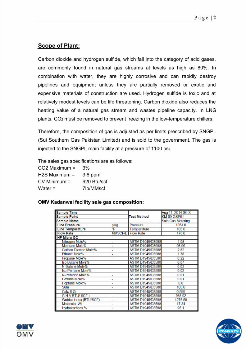
8102019 Gas sweetening Plant
httpslidepdfcomreaderfullgas-sweetening-plant 662
P a g e | 2
Scope of Plant
Carbon dioxide and hydrogen sulfide which fall into the category of acid gasesare commonly found in natural gas streams at levels as high as 80 In
combination with water they are highly corrosive and can rapidly destroy
pipelines and equipment unless they are partially removed or exotic and
expensive materials of construction are used Hydrogen sulfide is toxic and at
relatively modest levels can be life threatening Carbon dioxide also reduces the
heating value of a natural gas stream and wastes pipeline capacity In LNG
plants CO2 must be removed to prevent freezing in the low-temperature chillers
Therefore the composition of gas is adjusted as per limits prescribed by SNGPL
(Sui Southern Gas Pakistan Limited) and is sold to the government The gas is
injected to the SNGPL main facility at a pressure of 1100 psi
The sales gas specifications are as follows
CO2 Maximum = 3
H2S Maximum = 38 ppm
CV Minimum = 920 BtuscfWater = 7lbMMscf
OMV Kadanwai facility sale gas composition
8102019 Gas sweetening Plant
httpslidepdfcomreaderfullgas-sweetening-plant 762
P a g e | 3
OMV Kadanwai facility feed gas composition
Process Description
Gas from Kadanwari High pressure wells is routed to Kadanwari High Pressure
slug catcher Gas from Kadanwari low pressure wells is routed to Kadanwari low
pressure slug catcher and is fed to 2 stage Front End Compressor (FEC) to
increase the pressure up to production pressure Gas from FEC is fed to high
pressure stream flowing into Kadanwari High Pressure slug catcher The gas
from Miano wells is fed to Miano Slug Catcher
Kadanwari and Miano gas streams after separately metered are fed to a common
header which splits into two identical skids A and B Here we will discuss one
skid in common Each skid is routed to fin fan coolers where it is cooled and fed
to Inlet separator where water and heavy hydrocarbons are removed from feed
gas The condensate from all units is sent to produce water system
8102019 Gas sweetening Plant
httpslidepdfcomreaderfullgas-sweetening-plant 862
P a g e | 4
The gas then passes through pretreatment skid which consists of following units
Feed Cooler
Feed Gas Scrubber
Filter Coalescer
Feed Gas Heater
Activated Carbon Guard Filter
Particle Filter
Its main function is to remove contaminants from gas such as dust lube oils
heavy hydrocarbons etc which may poison or reduce efficiency of membrane
unit
After pretreatment gas is fed to Molecular Sieve Absorbers (Memguard Units)
which ensures gas supplied to membranes is up to membrane standards of UOP
(vendor of membrane system) It removes all moisture and heavy hydrocarbons
from gas stream
Pretreated gas is now fed to the primary membranes The permeate stream (rich
in CO2) is sent to recycle membranes after passing through recycle compressor
and recycle pretreatment The permeate stream of recycle membranes is used as
regenerative medium for Memguard units and rest is sent to incinerator and
burnt The residual gas (rich in CH4) from primary membrane and recycle
membranes (all skids) is sent to H2S polishers via a common header
H2S polisher unit reduce the hydrogen sulfide level to the sales limit The gas is
now metered after compressing in sales gas compressor and is sent to SNGPL
trunk line after metering
Water is remove from condensate at produced water system by a three phase
separator The condensate is sold to refinery Major quantity is exported to
various industries
8102019 Gas sweetening Plant
httpslidepdfcomreaderfullgas-sweetening-plant 962
P a g e | 5
Figure Overall plant Process Flow Diagram
8102019 Gas sweetening Plant
httpslidepdfcomreaderfullgas-sweetening-plant 1062
P a g e | 6
Wellhead
A wellhead is the component at the surface of an oil or gas well that provides the
structural and pressure-containing interface for the drilling and production
equipment Its function is to maintain surface control of the well It forms a seal to
prevent well fluids from leaking or blowing at the surface They are rated for
working pressure of 2000 psi to 15000 psi (or greater)
When the well has been drilled and it is ready to provide an interface with the
reservoir rock and a tubular channel for the well fluids The surface pressure
control is provided by a Christmas tree which is installed on top of the wellhead
with valves and choke equipment to control the flow of well fluids during
production
Christmas tree
A Christmas tree is an assembly of valves spools and fittings used for an oil
well gas well water injection well gas injection well condensate well and other
types of wells
The primary function of a tree is to control the flow usually oil or gas out of the
well When the well and facilities are ready to produce and receive oil or gas tree
valves are opened and the formation fluids are allowed to go through a flow line
This leads to a processing facility A tree often provides numerous additional
functions including chemical injection points well intervention means pressure
relief means monitoring points (such as pressure temperature corrosion
erosion sand detection flow rate flow composition valve and choke position
feedback) and connection points for devices such as down hole pressure andtemperature transducers (DHPT) On producing wells chemicals or alcohols or
oil distillates may be injected to preclude production problems (such as
blockages)
The control system attached to the tree controls the down-hole safety valve
(SCSSV) while the tree acts as an attachment and means of the control system
to the down-hole safety valve
8102019 Gas sweetening Plant
httpslidepdfcomreaderfullgas-sweetening-plant 1162
P a g e | 7
Figure 1
Well Head and Christmas Tree
8102019 Gas sweetening Plant
httpslidepdfcomreaderfullgas-sweetening-plant 1262
P a g e | 8
Master Valves
The two lower valves are called the master valves Master valves are normally in
the fully open position and are never opened or closed when the well is flowing
(except in an emergency) to prevent erosion of the valve sealing surfaces They
are gate type valves
1 Lower Master Valve (LMV)
2 Upper Master Valve (UMV)
The lower master valve will normally be manually operated while the upper
master valve is often hydraulically actuated allowing it to be used as a means of
remotely shutting in the well in the event of emergency
Wing Valve
A wing valve is normally used to shut in the well when flowing thus preserving
the master valves for positive shut off for maintenance purposes The wing
valve can be a gate valve or ball valve Hydraulic operated wing valves are
usually built to be fail safe closed meaning they require active hydraulic pressure
to stay open This feature means that if control fluid fails the well will
automatically shut itself in without operator action
In Kadanwari well sites there is only one manually operated wing valve On the
other hand at Miano well sites there are two wing valves one being operated
manually and other hydraulically
Production Wing Valve
The right hand valve is often called the flow wing valve or the production wing
valve because it provides flow path for hydrocarbons to production facility
Kill wing valve
The left hand valve is often called the kill wing valve It is primarily used for
injection of fluids such as corrosion inhibitors or methanol to prevent hydrate
formation It is typically manually operated It can kill the well temporarily be
injection brine solution which provides a pressure head to well and temporarily
8102019 Gas sweetening Plant
httpslidepdfcomreaderfullgas-sweetening-plant 1362
P a g e | 9
suspends it for maintenance of well head Also it is used to permanently kill the
well A chemical is injected down the well that seals the piping down the well and
kills the well permanently
Swab valve
The swab valve is used to gain access to the well for wire line operations
intervention and other work over procedure On top of it is a tree adapter
and cap that will mate with various equipment For such operations a
lubricator is assembled up onto the top of the tree and the wire or coil is lowered
through the lubricator through swab valve and into the well This valve is typically
manually operated
Choke
A choke holds back pressure by restricting the flow opening at the well head This
is done to make better use of the gas for natural gas lift and to control the bottom-
hole pressure for recovery reasons
CHECK VALVE
The check is introduced in production flow line to prevent any reverse flow from
the line into the well It has a hinged flap which lifts to permit normal flow but
closes to prevent reverse flow
TOP ADAPTOR
The top adaptor is a fitting on top of the swab valve with a threaded connection
During normal well operations a pressure gauge is fitted to monitor flowing and
shut in wellhead pressures However during well service operations the cap can
be removed to allow installation of lubricators for wire-line operations
SCSSSV (Surface Control Sub Surface Safety Valve)
A subsurface safety valve is essentially a shutdown valve installed at the upper
wellbore for emergency shutdown to protect the production tubing and wellhead
in case of overpressure Subsurface safety valves can offer a barrier against flow
in the event of a wellhead collapse or other disastrous event Purpose of asubsurface safety valve (SSSV) is to avoid the ultimate disaster which can result
8102019 Gas sweetening Plant
httpslidepdfcomreaderfullgas-sweetening-plant 1462
P a g e | 10
in release of reservoir fluids to the surroundings This makes SSSV a very
important component of a well completion
A subsurface safety valve is typically a uni-directional flapper valve directed in
such a way that the flappers open downwards when pressure is applied from an
upward direction The flapper can only open in the downward direction So even if
high pressure is applied by the well fluids from a
downward direction a safety valve can remain
closed This makes a subsurface safety valve fail-
safe To open the valve hydraulic signal is sent from
the surface well control panel This hydraulic
pressure is responsible for keeping the flappers of
SSSV open and loss of hydraulic pressure result in
closing of the valve Thus wellbore can be isolated in
case of system failure or damage to the surface
facilities
Types of Christmas tree
There are two types of Christmas Tree
1 Solid block
2 Conventional
The solid block Christmas Tree has a central solid unit holding several valves
in a pre-constructed block Their advantage is the reduction in potential leak
paths and their higher pressure rating (Fig 2)
The conventional Christmas Tree is built up from individual valves bolted
together to form an assembly (Fig 3)
8102019 Gas sweetening Plant
httpslidepdfcomreaderfullgas-sweetening-plant 1562
P a g e | 11
Figure 2
Figure 3
8102019 Gas sweetening Plant
httpslidepdfcomreaderfullgas-sweetening-plant 1662
P a g e | 12
Wellhead Control Panel
Wellhead control panel is key equipment in oil amp gas industry to protect oilfield
facilities and environment from emergency incidents such as wellhead fire which
is one of main control systems to ensure oilfield oil production and transportation
to be safely operation according to international standards and national
regulation Wellhead control panel is composed of hydraulic power unit tubing amp
fitting and instrument valve and electrical control devices Hydraulic power unit
supply hydraulic resource to open and close safety valves including master
valves wing valves and SCSSSV
Its performs
Local OnOff SSV
Remote control SSV through RTU( remote terminal unit)
High-Low pressure sense shut-down automatically
Fusible Plug Anti-fire Shut-down automatically
Function of showing system pressure
Relief Valve shall be installed on each hydraulic circuit to prevent high
pressure
Function of showing hydraulic level and level switch for alarm
Function of defending pressure impact of system
Function of system pressure monitoring (by pressure transmitter of control
panel)
Function of remote emergency shut-down (by magnetic valve of control
panel)
Function of OnOff SSV monitoring (by pressure switch of control loop of
control panel)
8102019 Gas sweetening Plant
httpslidepdfcomreaderfullgas-sweetening-plant 1762
P a g e | 13
Chemical Injection
Chemical injection systems are commonly used in production facilities to prevent
or eliminate a wide range of problems that might negatively affect the production
flow It is done for flow assurance protection of process equipment such as
pipelines or to optimize processes in production facilities
Typical flow assurance chemicals are
Wax inhibitors
Pour point depressants
Asphaltene inhibitors
Corrosion inhibitors
A corrosion inhibitor is a chemical compound that is added to liquid or gas to
decreases the corrosion rate of a material typically a metal or an alloy The
effectiveness of a corrosion inhibitor depends on fluid composition quantity of
water and flow regime Its common mechanism involves formation of a coating
8102019 Gas sweetening Plant
httpslidepdfcomreaderfullgas-sweetening-plant 1862
P a g e | 14
which prevents access of the corrosive substance to the metal The corrosive
agents are generally oxygen hydrogen sulfide and carbon dioxide
At our production site the major risk is corrosion of piping and equipment The
maximum allowable corrosion rate is approximately 02 mm per year and
corrosion rate without inhibitor could be approximately 11 mm per year so the
corrosion protection program is designed to achieve a target corrosion rate of
less than 01 mm per year which is achieved by an inhibitor system efficiency of
99 Inhibitor is injected into the well stream flow through an atomizing nozzle
located downstream of the respective wellhead coolers at the duplexcarbon steel
interface In normal operation as per NALCO standards chemical (brand name
EC1144B) at rate of frac12 Liter per MMSCFD of gas is being injected into the flow
line of miano15 flow lines made of carbon steel Moreover the composition can
vary depending upon the composition of well fluids and material of pipeline This
method of injection ensures even distribution of the chemical on the interior
surface of the pipeline The individual well sites are equipped with Chemical
Injection Packages comprising of a stainless steel storage tank and two
pneumatic motor driven pumps in parallel Instrument gas is used to drive the
pumps Normally one pump is running with the other standby
Water Conning
Water coning is a term used to describe the mechanism underlying the upward
movement of water into the perforations of a producing well Coning can seriously
impact the well productivity and influence the degree of depletion and the overall
recovery efficiency of the reservoir The specific problems of water coning are
listed below
Costly added water handling
Gas production from the original or secondary gas cap reduces pressure
Reduced efficiency of the depletion mechanism
The water is often corrosive and its disposal costly
The affected well may be abandoned early
Loss of the total field overall recovery
8102019 Gas sweetening Plant
httpslidepdfcomreaderfullgas-sweetening-plant 1962
P a g e | 15
Therefore conning has an important influence on operations recovery and
economics The phenomena is shown in picture below
Corrosion
Corrosion is referred as chemical deterioration of a metal Commonly this
means loss of electrons of metals reacting with water and oxygen
Weakening of iron due to oxidation of the iron atoms is a well-known
example of electrochemical corrosion This is commonly known as
rust Most structural alloys corrode merely from exposure to moisture
in the air but the process can be strongly affected by exposure to
certain substances Corrosion can be concentrated locally to form a pit
or crack or it can extend across a wide area to produce general
deterioration (uniform corrosion)
The following reaction takes place at the active sites
2Fe =gt 2Fe++ + 4e-
The free electrons travel through the metal path to the less active sites where
the following reaction takes place
O2 + 4e- + 2H20 =gt 4 OH-
8102019 Gas sweetening Plant
httpslidepdfcomreaderfullgas-sweetening-plant 2062
P a g e | 16
Recombination of these ions at the active surface produce the following
reaction which yields the iron-corrosion product ferrous hydroxide
2Fe + O2 + 2H2O =gt 2Fe (OH) 2
CORROSION PROTECTION SYSTEM
Coatings and painting
Painting and the application of enamel bitumen and PVC
coating are the most common anti-corrosion treatments They
work by providing a barrier of corrosion-resistant material
between the damaging environment and the structural material
Corrosion Inhibitors
Corrosion inhibitor is injected into the flow lines as mentioned in
detail on page 8
Cathodic Protection
Cathodic Protection (CP) is a technique used to control the corrosion of a
metal surface by making it the cathode of an electrochemical cell It
converts all of the anodic (active) sites on the metal surface to cathodic
(passive) sites by supplying electrical current (or free electrons) from an
alternate source It is accomplished in two ways
a) A simple method of protection connects protected metal to a more easily
corroded sacrificial metal to act as the anode The sacrificial metal then
corrodes instead of the protected metal The process is similar to a simple
DC cell in which the more active metal becomes the anode and corrodes
whereas the less active metal becomes the cathode and is protected
b) For larger structures galvanic anodes cannot economically deliver enough
current to provide protection Therefore impressed current cathodic
protection (ICCP) systems are used These consist of anodes connected
to a DC power source In remote areas power sources such as solar
panels may be used The output DC negative terminal is connected to the
8102019 Gas sweetening Plant
httpslidepdfcomreaderfullgas-sweetening-plant 2162
8102019 Gas sweetening Plant
httpslidepdfcomreaderfullgas-sweetening-plant 2262
P a g e | 18
frequently to limit liquid holdup and minimize the slug volumes of liquid which can
be generated by the system
Coating
Pigs may be used to apply internal pipe coatings such as epoxy coating
materials in operating pipelines Pigs may also be used with corrosion inhibitors
to distribute and coat the entire internal wetted perimeter
Inspection
Pigs are being used more frequently as inspection tools Gauging or sizing pigs
are typically run following the completion of new construction or line repair to
determine if there are any internal obstacles bends or buckles in the pipe Pigs
can also be equipped with cameras to allow viewing of the pipe internals
Electronic intelligent or smart ldquopigsrdquo that use magnetic and ultrasonic systems
have been developed and refined that locate and measure internal and external
corrosion pitting dents buckles and any other anomalies in the pipe wall
Intelligent pigs
The accuracy of location and measurement of anomalies by the intelligent pigs
has continued to improve Initially the electronics and power systems were so
large that intelligent pigs could be used only in lines 30 in and greater in size
The continued sophistication and miniaturization of the electronic systems used
in the intelligent pigs has allowed the development of smaller pigs that can be
used in small-diameter pipelines Newly enacted DOT pipeline-integrity
regulations and rules acknowledge the effectiveness of the intelligent pigs and
incorporate their use in the pipeline-integrity testing process
Compressors
A gas compressor is a mechanical device that increases the pressure of a gas by
reducing its volume Gas pressure is increased by forcing gas molecules together
to reduce gas volume When volume is reduced gas pressure increases
All gases have large spaces among their molecules These spaces could be
enhanced further and decreased by doing some work Work done which is used
8102019 Gas sweetening Plant
httpslidepdfcomreaderfullgas-sweetening-plant 2362
P a g e | 19
for the enhancement of these spaces is called expansion and work done to
minimize these spaces is called compression All gases while expansion
produces cooling effect and while compression of gases raises there
temperature Compression is a term used to force gases to occupy smaller
volumes by increasing their pressure Volume of gases is interlinked with
temperature and pressure of the gas which is cleared by 2 laws govern gas
compressions
Boyles Law
Charles Law
The main types of compressor are listed below
Front End Compressor
The plant currently processes gas from a number of wells The flow and pressure
from some of these wells (currently K-10 K-11 amp K-12) has declined and they
cannot be fed directly into the Central Processing Facility To recover the
maximum gas reserves from these wells a Front End Compressor is employed
The compressor is a two stage double acting gas engine driven reciprocating
(PT) compressor Double acting means that gas is compressed on each end of
the piston It normal operates with a speed range of 600 to 900 RPM and isequipped with four compressor cylinders two for each stage Each cylinder is
8102019 Gas sweetening Plant
httpslidepdfcomreaderfullgas-sweetening-plant 2462
P a g e | 20
also equipped with a variable volume head end pocket
In case of compressor emergency shutdown the production chokes and the
Upper Master Valves on the on line wells will close and operator will be notified in
central control room Sweet gas from gas distribution network is used to operate the
gas engine driver of the compressor package The detailed scheme of working is
shown in figure (page 22 )
PT Reciprocating Compressor
The mechanical cycle of piston tube reciprocating compressor comprises four
strokes the expansion stroke the intake stroke the compression stroke and the
discharge stroke
Expansion Stroke
As the piston moves back on the expansion stroke the chamber volume
increases and the pressure drop As the pressure drops the discharge valve
closes since there is greater pressure in the discharge line than in the chamber
Intake Stroke
As the piston moves back during the intake stroke the pressure decreases until it
is less than the pressure in the inlet line This higher intake pressure opens the
inlet valve and gas rushes into the cylinder equalizing the pressure there with
the intake pressure The compression chamber is now at or near the intake
pressure
Compression Stroke
The piston now starts the compression stroke by moving forward decreasing the
chamber volume and increasing the pressure The increased pressure is now
higher than the intake pressure causing the intake valve to close
Discharge Stroke
The piston continues to move to the left during the discharge stroke This creates
an increase in chamber pressure until it is greater than the discharge pressure
When this happens the Discharge valve opens and the compressed air from the
8102019 Gas sweetening Plant
httpslidepdfcomreaderfullgas-sweetening-plant 2562
P a g e | 21
cylinder goes into the discharge line The compression cycle is then repeated
from the stage
Compressor Capacity
The capacity of the compressor depends upon cylinder displacement That
displacement is simply the volume that the piston displaces (moves) as it travels
from one end of the cylinder to the other Capacity and displacement is equal to
the cross-sectional area of the cylinder times the length of the stroke
Lubrication and Cooling
Lubricating oil is circulated through the system by a gear pump which is chain
driven from the engine crank shaft The oil pump is mounted on the engine front
housing
The pump operates between 30 - 40 psig
8102019 Gas sweetening Plant
httpslidepdfcomreaderfullgas-sweetening-plant 2662
P a g e | 22
A circulating pump deliver cooling water to the water jackets in the cylinder block
flowing around the cylinder liners and is directed into the cylinder heads Each
cylinder head has water cooled exhaust elbows which outlet the water into the
water cooled exhausts From the end of engine the water flows to compressor
1st and 2nd stage cylinders and compressor lube oil cooler (LOwater heat
exchanger) The water from the compressor cylinder and lube oil cooler returns
to engine water cooled exhaust
Figure Flow diagram of Front End Compressor
8102019 Gas sweetening Plant
httpslidepdfcomreaderfullgas-sweetening-plant 2762
P a g e | 23
Centrifugal Compressor
Centrifugal compressors are machines in which velocity and pressure given to air
or gas in a radial direction by one or more impellers diffuser combination In a
centrifugal compressor the mechanical energy is increased by centrifugal action
The gas enters the suction eye of a high speed rotary element called the impeller
which carries radial vanes integrally cast in it As the impeller rotates the blades
of the impeller force the gas outward from the center the impeller to the outer rim
of impeller the increase in velocity of the gas creates a flow pressure area at the
eye of the impeller The gas at the outer rim of the impeller is forced in to a
passage way called a diffuser where the velocity decreases in the pressure of the
gas
Inlet
The inlet to a centrifugal compressor is typically a simple pipe It may include
features such as a valve and both pressure and temperature instrumentation
Centrifugal impeller
The key component that makes a compressor centrifugal is the centrifugal
impeller shown above It is the impellers rotating set of vanes (or blades) that
gradually raises the energy of the working gas This is identical to an axial
compressor with the exception that the gases can reach higher velocities and
energy levels through the impellers increasing radius
8102019 Gas sweetening Plant
httpslidepdfcomreaderfullgas-sweetening-plant 2862
P a g e | 24
Diffuser
The next key component to the simple centrifugal compressor is the diffuser
Downstream of the impeller in the flow path it is the diffusers responsibility to
convert the kinetic energy (high velocity) of the gas into pressure by gradually
slowing (diffusing) the gas velocity
SEPERATORS
A well-stream is a mixture of gases hydrocarbon liquids water solids and
contaminants Due to variations in pressure and temperature gases evolve from
the liquids water vapor condenses and some of the well-stream changes to liquid
and free gas The separation of well-stream fluids takes place in a separator This
pressure vessel is manufactured in three forms
1 horizontal
2 vertical
3 spherical
To help separation the vessel is normally designed with a series of internal
fittings These fittings are built into the separator to ensure total phase separation
of the well-stream
In gas plants separators are given alternative names due to the function they
perform in the process system A scrubber does a similar job to a knockout drum
However the scrubber usually separates a stream containing high gas-to-liquid
ratios The knockout drum is used where a high degree of liquids are entrained in
the gas
Fluid flow from a well can include gas condensable liquid vapors water water
vapor crude oil and solids As well-stream fluids reach ground level where
pressure is lower than in the reservoir the capacity of the liquid to hold gas in
solution decreases and gas separates out of the oil
Separation depends upon the effect of gravity to separate liquids For adequate
separation one fluid must be lighter than the other fluid For example distillates
8102019 Gas sweetening Plant
httpslidepdfcomreaderfullgas-sweetening-plant 2962
P a g e | 25
(gasoline kerosene etc) and crude oil will not separate in a vessel because they
tend to dissolve in each other Because a separator basically depends upon
gravity to separate the fluids the ease with which separation takes place
depends upon the difference in density of the fluids
Droplets of liquid will separate from gas provided
a) The gas remains in the separator long enough
b) The gas flow remains constant to provoke separation
The difference in density between a gas and liquid will therefore determine the
maximum flow rate of liquid in the vessel
Figure Two phase horizontal separator
Gas bubbles in the liquid will break out in some oil field applications in 30 to 60
seconds Consequently the separator is designed so that the liquid remains in
the vessel for 30 to 60 seconds The length of time that a liquid remains in the
vessel is called its residence time Residence time differs widely from field to field
depending upon viscosity and API Gravity
Another important factor which must be considered is temperature Generally a
decrease in operating temperature will increase the liquid recovery in a separator
8102019 Gas sweetening Plant
httpslidepdfcomreaderfullgas-sweetening-plant 3062
P a g e | 26
as the gas condenses By reducing the pressure on the fluid flash separation
occurs resulting in a flow through the separator which is controlled by external
instrumentation
COALESCENCE
Another important principle in fluid separation is that of coalescence This means
the coming together of liquid droplets created by the force of gravity
A common example of coalescing occurs when drops of water form on the
windshield of a car as it is driven in fog As the tiny drops or water which make up
the fog strike the windshield they combine and eventually form a drop large
enough to run down the glass
Several of the internal devices of a separator such as deflector plates
straightening vanes and even the vessel walls are forms of coalescers In each
vessel drops of liquid adhere to the surface of the device and combine with other
8102019 Gas sweetening Plant
httpslidepdfcomreaderfullgas-sweetening-plant 3162
P a g e | 27
drops until the drop is large enough to fall out The effectiveness of separation
will also depend upon the total amount of coalescing surface area that is present
There are many different types of separators used in the Oil amp Gas industry
Consequently separators are manufactured with one two or several internal
fittings depending on their use and quick removal of these fluids from the vessel
DEFLECTOR PLATES
These are fitted in front of the inlet to the separator and can be net or
dish-shaped Their purpose is to absorb the impact of the incoming fluids and to
encourage the separation of gas and liquids They also slow the flow rate of the
liquids through the vessel
WEIRS
A weir is a metal wall which is fitted across the inside of the vessel normally to a
height of 50 of the overall height of the separator Its purpose is to assist the
process of three phase separation The inlet fluids (oil plus water) are given time
to separate in the liquid accumulation section The water level (interface) is
normally controlled at 50 of the height of the weir Oil floating on the wateroverflows the weir and accumulates in the small oil compartment where it is
drawn off under level control
CENTRIFUGAL DEVICES
These are used in both vertical and horizontal separators for gas-liquid
separation The device imparts a swirling motion to the fluids entering the vessel
Centrifugal force causes the heavier liquids to travel outwards towards the walls
of the vessel and the lighter gases to flow up the centre Centrifugal devices are
also known as cyclones
VORTEX BREAKERS
When liquid flows through a drain outlet a vortex (whirlpool) will form This can
be seen when we pull the plug from a sink or bath tub The same would happen
as water and oil flow from the separator This condition a vortex could allow gas
to flow down the centre of the whirlpool and enter the liquid phase causing
8102019 Gas sweetening Plant
httpslidepdfcomreaderfullgas-sweetening-plant 3262
P a g e | 28
pressurizing of tanks etc To stop this happening vortex breakers are fitted to all
liquid outlets Although they come in a number of different designs vortex
breakers all serve the same purpose - to prevent a whirlpool from forming
MIST OR DEMISTER PADS
The gas which is released from the fluids in the separator still contains droplets of
oil and water which coalesce and fall when the drops get large enough The
demister pad assists in this process Made from knitted wire and contained within
a sturdy frame it causes the gas to continually change its direction of flow
Because gas changes direction far easier than liquid the gas will flow around
each strand of wire whilst the liquid entrained in the gas stream will continue and
stick to the wire
COALESCING PLATES
There are several different forms of coalescing devices the most common of
which are coalescing plates These plates are mounted in the flow stream of the
fluids and assist in breaking down oil-water emulsions The fluid is forced to
follow a path that constantly changes direction This causes the water droplets to
gather together or coalesce and fall to the bottom of the separator The same
principle is used to separate gas and oil mixtures when the oil droplets are
induced to coalesce Simply stated every surface within the separator including
the separator walls assists with the coalescing process
STRAIGHTENlNG VANES
These are often fitted to horizontal separators to remove turbulence in the gas
stream after initial separation at the inlet deflector
FLOAT SHEILD
Internal floats are used as level controllers Any agitation of the liquid surface or
the effect of coalesced liquids falling on the float may cause control problems
Therefore a float shield is fitted to enclose the float creating an area of still liquid
8102019 Gas sweetening Plant
httpslidepdfcomreaderfullgas-sweetening-plant 3362
P a g e | 29
MEMBRANES
The gas contains 12 carbon dioxide and 22 ppm of hydrogen sulphide at 115oF
and 1100 psig This needs to be removed before the gas can be exported The
majority of carbon dioxide hydrogen sulphide and water is removed by means of
membranes
Membranes are thin semipermeable barriers that selectively separate some
compounds from others Currently the only commercially workable membranes
used for CO2 removal are polymer based for example cellulose acetate
polyimides polyamides polysulfone polycarbonates and polyetherimide The
membrane does not operate as a filter where small molecules are separated
from larger ones through a medium with pores rather it separates based on how
well different compounds dissolve into the membrane and diffuse through it The
membranes are manufactured in flat sheets consisting of an extremely thin
nonporous layer mounted on a much-thicker and highly porous layer of the same
material providing mechanical strength The flat sheets are combined into a
spiral-wound element (Figure below) Feed gas enters along the side of the
membrane and passes through the feed spacers As the gas travels between
membrane sheets CO2 H2S and H2O permeate through the membrane and are
collected in the permeate tube The driving force for transport is the high-feed
pressure and low-permeate pressures The gas on the feed side that does not
permeate leaves through the side of the element opposite the feed position Once
the membranes have been manufactured into elements six to 12 elements are
joined together and inserted into a tube Multiple tubes are mounted on skids in a
horizontal orientation
8102019 Gas sweetening Plant
httpslidepdfcomreaderfullgas-sweetening-plant 3462
P a g e | 30
Figure Membrane general Working
In high H2S applications most polymers have been shown to have very little
resistance to H2S plasticization (ldquosofteningrdquo of the membrane) and as a
consequence can only be used at very low H2S partial pressure limits Cellulose
acetate membranes in contrast have been shown to be applicable at extreme
H2S partial pressure conditions It is these membranes that have been utilized in
the testing to determine the limits of membrane performance in high H 2S
applications
The primary membranes used in Kadanwari facility are Cellulose acetate
Cellulose acetic acid and acetic anhydride are mixed together and reacted to
form cellulose acetate polymers This process is aided by the addition of a small
amount of sulfuric acid which is subsequently neutralized during processing
However the membranes are bought from UOP (vendor) and installed for use
8102019 Gas sweetening Plant
httpslidepdfcomreaderfullgas-sweetening-plant 3562
P a g e | 31
How membrane work
The basic principle of separation is selectivity of certain components of a mixture
for the membrane For example the cellulose acetate membrane has very high
selectivity for CO2 and H2S as compared to CH4 Therefore such type of
membrane can be used in gas sweetening process
The selectivity is directly related to the Permeability of gas which accounts that
which gas can pass across the membrane more easily In simple words
membranes being polymer materials are made of long chains of molecules The
different structure of polymer materials only allow selective molecules to pass
through them depending upon chemical and physical compatibility Thus
permeability depends upon choice of polymer
The permeability is determined by permeability coefficient (P) and is product of
solubility (S) and diffusivity (D)
P = S D
Solubility
The solubility is mainly determined by ease of condensation Heavy molecules
are more readily condensed Therefore higher molecular weighted molecules will
more easily condensed and therefore have greater solubility
Molecule Molecular weight
CH4 16
H2S 34
CO2 44
8102019 Gas sweetening Plant
httpslidepdfcomreaderfullgas-sweetening-plant 3662
P a g e | 32
Diffusivity
Diffusivity is ease of molecule to penetrate into some material It depends on size
of gas molecule Here size of molecule is not to be confused by molecular weight
it is the size of the structure Eg the size of O2 molecule is smaller than N2
Molecule Molecular Diameter (Ao)
CO2 33
H2S 36
Ch4 40
For cellulose acetate
DCO2DCH4 S CO2S CH4 P CO2P CH4
45 73 308
Chemical degradation
Cellulose acetate polymer is chemically degraded by a process called hydrolysis
which means breaking apart by the addition of water This is a chemical reaction
in which water is added to the cellulose acetate polymer causing the release of
acetic acid molecules This process proceeds stepwise until all the acetate
groups are released resulting in the reformation of cellulose Moreover alcohols
aromatic hydrocarbons or solvents with chlorine nitro benzene or similar
aromatic solvents will harm the membrane It will expand and lose plastification in
contact with them
Effect of Temperature
The permeation rates of all gases increases with increasing temperature
however membrane selectivity for CO2 over hydrocarbon decreases at higher
8102019 Gas sweetening Plant
httpslidepdfcomreaderfullgas-sweetening-plant 3762
P a g e | 33
temperature Consequently CO2 removal will improve as operating temperature
increases but hydro carbon recovery will decrease
Primary Membrane
The primary membranes comprise of two trains Each train consists of two
sections AB and CD each section consists of a 30 tube membrane skid (A and
C) followed by a 25 tube skid (B and D) The conditioned gas (after pre-
treatment) enters the primary membrane via the particulate filter adjacent to the
skid The gas is fed to the membranes through a common inlet manifold which
supplies primary membranes skids A and C A pressure control loop located
upstream of the manual inlet isolation valve is provided to maintain a constant
supply pressure to the membrane skid and to allow for preheating at the inlet
prior to skid start-up This pressure control loop can also be used during start-up
to control the pressurization of the pretreatment skid and associated pipes to the
primary membranes
The gas passes through membrane skid A the residual gas exiting the membrane
skid is sent to skid B and the permeate to common permeate discharge header An
identical arrangement is provide on the inlet to skid C as provided on skid A Theresidual gas from skid B combines with the residual gas from skid D in a common
discharge header and is then sent to the H2S polishing towers via the feed coolers
on the pre-treatment skid The permeate from skid B is sent to the common
permeate discharge header The permeate discharge header sends the gas to
either the recycle compressor or the vent header via a pressure control loop
Overpressure protection for the membranes is provided by a pressure safety valve
on the supply header to the membrane banks
8102019 Gas sweetening Plant
httpslidepdfcomreaderfullgas-sweetening-plant 3862
P a g e | 34
Secondary (Recycle) Membrane
The recycle membranes comprise of a single train with two skids each with four
banks of membrane tubes The conditioned gas from the discharge of the recycle
pre-treatment skid is routed to the first recycle membrane skid The gas passes
through the membranes the residual gas is fed to primary membrane (skid A) inlet
via feed gas cooler and permeate to the common permeate discharge header An
identical arrangement is provide on the inlet to skid B Permeate from the recycle
membrane skids A and B is routed to the vent header Some portion of permeate is
heated and sent for regeneration in Mem-Guard units Nitrogen purge can be
connected downstream of the inlet isolation valve on each skid to enable the
membrane tubes to be purged and left pressurized during prolonged shutdown
8102019 Gas sweetening Plant
httpslidepdfcomreaderfullgas-sweetening-plant 3962
P a g e | 35
Figure Flow Diagram of Recycle membrane unit
8102019 Gas sweetening Plant
httpslidepdfcomreaderfullgas-sweetening-plant 4062
P a g e | 36
ADVANTAGES OF MEMBRANE SYSTEMS
Membrane systems have major advantages over more-traditional methods of
acid gas removal
Lower capital cost Membrane systems are skid mounted and so the
scope cost and time taken for site preparation are minimal Installation
costs are significantly lower than alternative technologies especially for
remote areas Furthermore no additional facilities for solvent storage and
water treatment needed by other processes are required
Lower operating costs The only major operating cost for single-stage
membrane systems is membrane replacement This cost is significantly
lower than the solvent replacement and energy costs associated with
traditional technologies The improvements in membrane and
pretreatment design allow a longer useful membrane life which further
reduces operating costs The energy costs of multistage systems with
large recycle compressors are usually comparable to those for traditionaltechnologies
Deferred capital investment Often contracted sales-gas flow rates
increase over time as more wells are brought on-line With traditional
technologies the system design needs to take this later production into
account immediately and so the majority of the equipment is installed
before it is even needed The modular nature of membrane systems
means that only the membranes that are needed at start-up need be
installed The rest can be added either into existing tubes or in new skids
only when they are required
Operational simplicity and high reliability Because single-stage
membrane systems have no moving parts they have almost no
8102019 Gas sweetening Plant
httpslidepdfcomreaderfullgas-sweetening-plant 4162
P a g e | 37
unscheduled downtime and are extremely simple to operate They can
operate unattended for long periods of time The addition of a recycle
compressor adds some complexity to the system but still much less than
with a solvent- or adsorbent-based technology Multistage systems can be
operated at full capacity as single-stage systems when the recycle
compressor is down
Good weight and space efficiency Skid construction can be optimized
to the space available This space efficiency is especially important for
offshore environments where deck area is at a premium and is the
reason why so many new offshore developments have chosen to use
membranes for acid gas removal Figure 6 illustrates the space efficiency
of membrane systems The membrane unit in the lower left corner
replaced all the amine and glycol plant equipment shown in the rest of the
picture
Adaptability Because membrane area is dictated by the percentage of
acid gas removal rather than absolute acid gas removal small variations
in feed acid gas content hardly change the sales-gas acid gas
specification For example a system designed for 10 down to 3 acid
gas removal produces a 35 product from a 12 feed gas and a 5
product from a 15 feed gas
Design efficiency The membrane and pretreatment systems integrate a
number of operations such as dehydration CO2 and H2S removal dew-
point control and mercury removal Traditional acid gas removal
technologies require all of these operations as separate processes and
may also require additional dehydration because some technologies
saturate the product stream with water
8102019 Gas sweetening Plant
httpslidepdfcomreaderfullgas-sweetening-plant 4262
P a g e | 38
Power generation The permeate gas from membrane systems can be
used to provide fuel gas for power generation either for a recycle
compressor or other equipment
Ideal for debottlenecking Because expanding solvent- or adsorbent-
based acid gas removal plants without adding additional trains is difficult
an ideal solution is to use membranes for bulk acid gas removal and leave
the existing plant for final cleanup An additional advantage is that the
permeate gas from the membrane system can often be used as fuel for
the existing plant thus avoiding significant increase in hydrocarbon
losses
Environmentally friendly Membrane systems do not involve the
periodic removal and handling of spent solvents or adsorbents Permeate
gases can be flared used as fuel or re-injected into the well Items thatdo need disposal such as spent membrane elements can be incinerated
Ideal for remote locations Many of the factors mentioned above make
membrane systems a highly desirable technology for remote locations
where spare parts are rare and labor unskilled Furthermore solvents
storage and trucking water supply power generation or extensive
infrastructure are not required
Re-injection optimizations Since the permeate stream from the
membrane system can be operated at elevated pressures it is possible to
further pressurize by re-injection compression train
8102019 Gas sweetening Plant
httpslidepdfcomreaderfullgas-sweetening-plant 4362
P a g e | 39
Sorption
Sorption is a physical and chemical process by which one substance becomes
attached to another
It is of two main types
1 Absorption
2 Adsorption
Absorption
Absorption is a physical or chemical phenomenon or process in which atoms
molecules or ions enter some bulk phase ndash gas liquid or solid material This is a
different process from adsorption since molecules undergoing absorption are
taken up by the volume not by the surface (as in the case for adsorption)
Absorption process may be chemical (reactive) or physical (non-reactive)
Physical absorption
Physical absorption or non-reactive absorption is made between two phases ofmatter a liquid absorbs a gas or a solid absorbs a liquid
When a liquid solvent absorbs a gas mixture or part of it a mass of gas moves
into the liquid For example water may absorb oxygen from the air This mass
transfer takes place at the interface between the liquid and the gas at a rate
depending on both the gas and the liquid This type of absorption depends on the
solubility of gases the pressure and the temperature The rate and amount of
absorption also depend on the surface area of the interface and its duration in
time
When a solid absorbs a liquid mixture or part of it a mass of liquid moves into the
solid For example a clay pot used to store water may absorb some of the water
This mass transfer takes place at the interface between the solid and the liquid
at a rate depending on both the solid and the liquid
8102019 Gas sweetening Plant
httpslidepdfcomreaderfullgas-sweetening-plant 4462
P a g e | 40
Chemical absorption
Chemical absorption or reactive absorption is a chemical reaction between the
absorbed and the absorbing substances Sometimes it combines with physical
absorption This type of absorption depends upon the stoichiometry of the
reaction and the concentration of its reactants
Adsorption
Adsorption is the adhesion of atoms ions or molecules from a gas liquid or
dissolved solid to a surface This process creates a film of the adsorbate on the
surface of the adsorbent The binding to the surface is usually weak and
reversible Compounds with color and those that have taste or odor tend to bind
strongly Compounds that vibrate at frequencies in the visible spectrum are very
often are strongly adsorbed on activated carbon
The most common industrial adsorbents are activated carbon silica gel and
alumina because they present enormous surface areas per unit weight
Depending on the nature of attractive forces existing between the adsorbate and
adsorbent adsorption can be classified as
i) Physical adsorption
ii) Chemical adsorption
i) Physical adsorption (Physisorption)
In physical adsorption the forces of attraction between the molecules of the
adsorbate and the adsorbent are of the weak van der Waals type Since the
forces of attraction are weak the process of physisorption can be easily reversed
by heating or decreasing the pressure of the adsorbate (as in the case of gases)
8102019 Gas sweetening Plant
httpslidepdfcomreaderfullgas-sweetening-plant 4562
P a g e | 41
ii) Chemical adsorption (Chemisorption)
In chemisorption the forces of attraction between the adsorbate and the
adsorbent are very strong the molecules of adsorbate form chemical bonds with
the molecules of the adsorbent present in the surface
Adsorption is generally accompanied by release of energy that is most
adsorption processes are exothermic in nature Adsorption is a spontaneous
process therefore its free energy change is negative (∆Glt0) However the
entropy change associated with adsorption is generally negative because the
adsorbate molecules lose their translation freedom when they get attached to the
surface of the adsorbent Therefore in order for ∆G to be negative the enthalpy
change (∆H) must be sufficiently negative such that (∆G=∆H-T∆S) lt 0 This
explanation accounts for exothermic adsorption processes In cases where
endothermic adsorption occurs the entropy change ∆S is sufficiently positive
such that ∆G remains negative
Pre treatment
The main function of pretreatment skid is to provide membrane inlet specification
gas as mentioned by the vendor UOP It removes the contaminants that would
poison the membranes like dust solids (adsorbent particles) lube oil heavy
hydrocarbons etc It consists of
Feed Cooler
Feed Gas Scrubber
Filter Coalescer
Feed Gas Heater
Activated Carbon Guard Filter
Particle Filter
8102019 Gas sweetening Plant
httpslidepdfcomreaderfullgas-sweetening-plant 4662
8102019 Gas sweetening Plant
httpslidepdfcomreaderfullgas-sweetening-plant 4762
P a g e | 43
The regeneration is carried out by heated permeate gas from the recycle
membranes at 450oF The vessel is depressurized to 20 psi and heated gas is
introduced from top The gas carries out the adsorbed contaminants and leaves
the vessel from bottom cleaning the adsorbent This contaminated gas is burnt in
the flare
UOP the vendor of Memguard unit has never disclosed that what substance
MG3 and MG5 exactly are But as mentioned by vendor that both care class of
aluminosilicates Therefore MG3 can be potassium aluminosilicate and MG5 can
be Calcium aluminosilicate These are molecular sieves adsorbents Molecular
sieves are a microporous material which can selectively adsorb gases andliquids They are synthetic zeolites (crystalline metal aluminosilicates) which
upon dehydration can efficiently and selectively remove water or other
solvents The selectivity of a molecular sieve is determined by its pore size
molecules with a critical diameter which is less than the pore size will be
efficiently adsorbed while larger molecules will be excluded
8102019 Gas sweetening Plant
httpslidepdfcomreaderfullgas-sweetening-plant 4862
P a g e | 44
3A Molecular Sieve Adsorbent
The 3A molecular sieve adsorbent has a 3 angstrom (3A) pore size which means
that any molecule that is larger than the 3 angstrom pores will not be adsorbed
The 3A molecular sieve is the potassium type of A crystalline structure and is a
form of alkali Aluminosilicate For a 3A molecular sieve the sequence rate that
adsorption occurs is He Ne N and H2O
Due to the crystalline structure molecular sieves that have a 3 angstrom pore
size have a very high rate of adsorption and properties that promote a longer life
for products treated by the sieve The most common use for the 3A molecular
sieve is to remove water and moisture from materials that are in gas and liquid
form
5A Molecular Sieve Adsorbent
These are molecular sieve adsorbents with a pore size of 5 angstrom (5A) 5A
molecular sieves are unable to adsorb any molecules or impurities that are
smaller than 5A It is calcium form of type A crystalline structure and is form of analkali-aluminosilicate that is most commonly used to separate isomerous alkanes
from normal alkanes and to co-adsorb moisture and water along with carbon
dioxide from gases In additional 5A molecular sieves are used for gaseous
pressure swing adsorption (PSA)mdashthat is to separate particular gases from other
gases
Adsorption of nC4H10
Adsorption of nC4H10
Adsorption of C3H8 to C22H46
Adsorption of Freon-12 (dichlorodifluoromethane)
Natural gas drying
Normal- and iso-paraffin separation
Separation of aromatic
8102019 Gas sweetening Plant
httpslidepdfcomreaderfullgas-sweetening-plant 4962
P a g e | 45
Inlet Composition of Memguard vessel
COMPSOSITION MOLE
CARBON DIOXIDE 1096
MEHTANE 8593
ETHANE 173
PROPANE 023
I-BUTANE 008
N BUTANE 004
PENTANES 004
HEXANE + 000
NITROGEN 076
WATER 007
Outlet Composition of Memguard vessel
COMPSOSITION MOLE
CARBON DIOXIDE 1098
MEHTANE 8608
ETHANE 173
PROPANE 023
I-BUTANE 008N BUTANE 004
PENTANES 004
HEXANE + 000
NITROGENT 076
WATER 000
H2S polisher
The H2S polishing unit has been designed to treat 187 MMscfday of natural gas
containing up to 11 CO2 and 21 ppm H2S where the level of the CO2 and H2S
is reduced using a MemGuard Membrane separation unit The unit is situated
down-stream of the membrane unit and will further reduce the level of H2S in the
processed gas to a sales gas specification of 38 ppm
8102019 Gas sweetening Plant
httpslidepdfcomreaderfullgas-sweetening-plant 5062
P a g e | 46
This process uses three non-regenerable fixed bed absorber vessels using a low
temperature high activity absorbent The absorbent is a mixture of activated
metal oxides (mainly zinc oxide) The three towers can are generally operated in
parallel arrangement but on demand can be used in series (any of alternate
arrangements of A B C vessels) as shown in figure
The higher sales gas flow rate increased the catalyst consumption and
replacement frequency
ZnO + H2S =gt ZnS + H20
Routine samples are taken from the beds to provide a check on each bed
performance and to follow the saturation profile during the absorbent life After
the adsorbent has been fully utilized the adsorption vessels are recharged with
new adsorbent discarding the utilized one in a safe manner
109oF
1215 psig
Before H2S Polishing After H2S Polishing
8102019 Gas sweetening Plant
httpslidepdfcomreaderfullgas-sweetening-plant 5162
P a g e | 47
Figure
H2S Tower
Inlet pipe
4 Drums of 19mm
ceramic Balls
6 Micron mesh
5 Drums of 50mmceramic
1 Drums of19mm ceramic
01 Drums of6mm ceramic
112 drums of
Catalist ZnO
8102019 Gas sweetening Plant
httpslidepdfcomreaderfullgas-sweetening-plant 5262
P a g e | 48
Recycle Compressor
The permeate gas of the primary membrane unit carries recoverable amount of
CH4 It is fed to recycle membrane unit for further CH 4 recovery But the
permeate pressure from primary membranes which has been reduced to 12 psi
must be regenerated to 1200 psi for the gas to be fed again to the system For
this purpose we have employed recycle compressor The compressor is a four
stage centrifugal compressor It is driven by gas turbine of 31200 HP It has 25
MW producing capacity
Figure Recycle Compressor Process Flow Diagram
8102019 Gas sweetening Plant
httpslidepdfcomreaderfullgas-sweetening-plant 5362
P a g e | 49
Sales Gas Compressor
Gas from H2S polishing unit is sent to sales gas compressor where its pressure
is enhanced to 1100 psi so it may be injected to SNGPL high pressure trunk line
Sales gas compressor is single stage gas turbine driven
Figure Process Flow of Sales Gas Compressor
8102019 Gas sweetening Plant
httpslidepdfcomreaderfullgas-sweetening-plant 5462
P a g e | 50
Cooling Towers
A cooling tower is a heat rejection device which extracts waste heat to theatmosphere through the cooling of a water stream to a lower temperature Hot
water from the system enters the cooling tower and is distributed over the fill
(heat transfer surface) Air is induced or forced through the fill causing a small
portion of the water to evaporate This evaporation removes heat from the
remaining water which is collected in the cold water basin and returned to the
system to absorb more heat Each cooling tower line although operating under
the same basic principle of operation is arranged a little differently
Types
Natural draft mdash Utilizes buoyancy via a tall chimney Warm moist air naturally
rises due to the density differential compared to the dry cooler outside air Warm
moist air is less dense than drier air at the same pressure This moist air
buoyancy produces an upwards current of air through the tower
Mechanical draft mdash Uses power-driven fan motors to force or draw airthrough the tower
o Induced draft mdash A mechanical draft tower with a fan at the
discharge (at the top) which pulls air up through the tower The fan
induces hot moist air out the discharge This produces low entering
and high exiting air velocities reducing the possibility of
recirculation in which discharged air flows back into the air intake
o Forced draft mdash A mechanical draft tower with a blower type fan at
the intake The fan forces air into the tower creating high entering
and low exiting air velocities The low exiting velocity is much more
susceptible to recirculation This fanfill geometry is also known as
blow-through
8102019 Gas sweetening Plant
httpslidepdfcomreaderfullgas-sweetening-plant 5562
P a g e | 51
Forced Draft Cooling Tower Vs Induced Draft Cooling Tower
Induced Draft Cooling Tower have the ability to handle large water flow
rate than Forced Draft Cooling Tower
Induced Draft Cooling Tower is suitable for large cell sizes and fan sizes
as compared with Forced Draft Larger fan size may result in greater
efficiency and consequently lower power and sound level
Forced Draft Cooling Tower can be square or rectangular type only
however Induced Draft Cooling Towers can be round square or
rectangular type
Induced Draft Cooling Tower uses more compact ground area than Forced
Draft Cooling Tower equivalent capacity due to absence of fan on one
side
Fan equipment is warm exhaust air is less liable to icing up in winter
operation (Cold Countries)
Higher velocity in Forced Draft Cooling Tower cause drop in suspension
and cause additional static resistance to system
Configuration
There are two main configurations of factory assembled cooling towers crossflow
and counterflow In crossflow cooling towers the water flows vertically down the
fill as air flows horizontally across In counterflow cooling towers the water flows
vertically down the fill as air flows vertically up
Crossflow Configuration Counterflow Configuration
8102019 Gas sweetening Plant
httpslidepdfcomreaderfullgas-sweetening-plant 5662
P a g e | 52
Drift mdash Water droplets that are carried out of the cooling tower with the exhaust
air Drift droplets have the same concentration of impurities as the water entering
the tower The drift rate is typically reduced by employing baffle-like devices
called drift eliminators through which the air must travel after leaving the fill and
spray zones of the tower
Blow-out mdash Water droplets blown out of the cooling tower by wind generally at
the air inlet openings Water may also be lost in the absence of wind through
splashing or misting Devices such as wind screens louvers splash deflectors
and water diverters are used to limit these losses
Blow-down mdash The portion of the circulating water flow that is removed (usually
discharged to a drain) in order to maintain the amount of Total Dissolved Solids
(TDS) and other impurities at an acceptably low level Higher TDS concentration
in solution may result from greater cooling tower efficiency However the higher
the TDS concentration the greater the risk of scale biological growth and
corrosion
Make-up mdash The water that must be added to the circulating water system in
order to compensate for water losses such as evaporation drift loss blow-out
blow-down etc
Approach mdash The approach is the difference in temperature between the cooled-
water temperature and the entering-air wet bulb temperature
Range mdash The range is the temperature difference between the warm water inlet
and cooled water exit
Fill mdash Inside the tower fills are added to increase contact surface as well as
contact time between air and water to provide better heat transfer The efficiency
of the tower depends on the selection and amount of fill
8102019 Gas sweetening Plant
httpslidepdfcomreaderfullgas-sweetening-plant 5762
P a g e | 53
There are two types of fills that may be used
o Film type fill (causes water to spread into a thin film)
o Splash type fill (breaks up falling stream of water and interrupts its
vertical progress)
Important
Scale build up is controlled by adding chemicals to the cooling loop and diluting
the concentration by blow down and make-up Following chemicals are added to
the Cooling to control CorrosionSale and microbial growth
Corrosion Inhibitor To control corrosion in the Cooling system
Dispersant To kept ions in suspension to avoid settle down and buildup
Sodium hypo Chlorite To Control microbial Growth
Acid To control Alkalinity in the system
High Stress Polymer To run the system at higher conductivity It is a
multifunctional polymer for Zinc amp Phosphate stabilization in cooling tower
Fin Fan Cooler
Fin fan heat exchanger is simply a pressure vessel which cools a circulating fluid
within finned tubes by forcing ambient air over the exterior of the tubes A
common example of an air cooler is a carrsquos radiator Fin Fan Coolers are used in
any application where large quantities of heat need to be transferred This
includes chemical and petrochemical industries power stations waste-to-energy
facilities as well as steelworks
Fin Fan Cooler are used for two primary reasons
They increase plant efficiency
They are a green solution as compared to cooling towers and shell and
tube heat exchangers because they do not require an auxiliary water
8102019 Gas sweetening Plant
httpslidepdfcomreaderfullgas-sweetening-plant 5862
P a g e | 54
supply (water lost due to drift and evaporation plus no water treatment
chemicals are required)
Figure General Overview of Fin Fan Cooler
Produced Water
The produced water system receives liquid from the equipment Miano slug
catcher train 1 and 2 inlet separators and is fed to three phase separator where
water oil and gas is separated The gases produced are burnt in incinerator
whereas hydrocarbon liquid is stored to be sold Liquid from compressors
recycle inlet separator recycle feed scrubber high and low pressure slug
catchers is passed to degasser Separated water is injected down the earth
Incinerator
The term incinerate means to burn something until nothing is left but ashes An
incinerator is a unit or facility used to burn trash and other types of waste until it is
reduced to ash An incinerator is constructed of heavy well-insulated materials
so that it does not give off extreme amounts of external heat The high levels of
heat are kept inside the furnace or unit so that the waste is burned quickly and
efficiently If the heat were allowed to escape the waste would not burn as
completely or as rapidly
8102019 Gas sweetening Plant
httpslidepdfcomreaderfullgas-sweetening-plant 5962
P a g e | 55
Control System
The plant is controlled at CCR (Central Control Room) by PLCs (Programmable
Logic Controllers) through fiber optic control line All control parameters are
received at LER (Local Equipment Room) via two optic fiber control lines One
being primary and other secondary operating in redundancy ie if primary fails
control shifts to secondary These control parameters are sent to CCR via single
optic fiber cable
Safety System
Wellheads and Gas Processing Plant have their own Fire amp Gas detection
systems emergency shutdown (ESD) Plant has a fault tolerant controller It is
based on Triple Modular Redundant (TMR) architecture manufactured by
Triconex The TMR system is based on three isolated parallel control systems
integrated into one system The system operates on a two out of three voting
principle which provides high integrity error free uninterrupted operation with no
single point of failure The TMR receives inputs from Process Sensors Manual
Switches Fire amp Gas Detectors Packaged Equipment Control Systems and
Product Exporting Facilities The TMR carries out cause and effect processing on
the data received and where necessary produces output signals Outputs from
the TMR are hard wired directly to ESD shutdown and blow down valve
solenoids motor control instrumentelectrical interfaces to control electrical
drives package equipment logic control systems manifold area as well as
telecoms
The operator in central control room is able to accept alarms and once the fault
has been cleared reset the input All the control systems are centralized to a
single interface All the PLCs (Programmable Logic Controllers) communicate with
the servers and servers communicate with the clients through Ethernet connectivity
Centralization eases the navigation of different systems at a common interface
Emergency Shutdown
The ESD system receives inputs from field mounted instrumentation on the process
8102019 Gas sweetening Plant
httpslidepdfcomreaderfullgas-sweetening-plant 6062
P a g e | 56
and utility equipment and initiates executive actions appropriate to the level of ESD
The system is an Active system which is in standby and will activate when in an
alarm or fault condition The Kadanwari Gas Process Facility ESD system is
comprised of five (5) levels The emergency severity decreases with increasing ESD
level number
ESD 1
This shutdown level is automatically initiated by fire major gas leak or a detected
toxic atmosphere in the process area of the plant or manually from CCR A level 1
shutdown will cause all production to cease close all emergency shutdown
valves stop the process and shutdown of the main power generation The
emergency vent valves to the stack will open and in addition all equipment of zone 1
certified will be isolated This is the highest level of ESD and will cause the following
to occur
All Shutdown Valves (SDVs) on the process facility will close All slowdown Valves (BDVs) on the process facility will open
All Main Gas Driven Generators will be tripped
Emergency Diesel Generator will start
All electrical power to process and utility rotating equipment will be
isolated
Wellhead Choke Valves Close Wing Valves Close Upper Master Valve
(UMV) Close
ESD 2
This shutdown level is activated automatically if a major process or utility failure
occurs or manually from CCR All production to the plant from the wellhead is
stopped All emergency shutdown valves trip to their fail safe position
Venting shall be as specified This level of ESD will cause the following to occur
8102019 Gas sweetening Plant
httpslidepdfcomreaderfullgas-sweetening-plant 6162
P a g e | 57
All Shutdown Valves (SDVs) on the process facility will close
All electrical power to process and utility rotating equipment will be
isolated
Wellhead Choke Valve Close Wing Valves Close and Upper Master Valve(UMV) Close
ESD 3
The level 3 shutdown isolates and stops a single process train only Production
continues via the other train This ESD level is initiated by process conditions or
operator at local panel This level of ESD will cause the following to occur
ESD 3A Train 1 production to cease
ESD 3B Train 2 production to cease
All online wellhead choke valves go to minimum flow ie (1O )
ESD 4
A level 4 shutdown shall cease all production from an entire field either
Kadanwari or Miano upstream of the associated slug catchers ESD 4K for
Kadanwari amp ESD 4M for Miano This ESD level is initiated automatically by slug
catcher abnormal process conditions This level of ESD will cause the following
to occur
All SDVs close isolating the relevant slug catcher and its upstream gas
production facility from the Kadanwari Gas Processing Plant
All Wellhead Choke Valves Close Wing Valves Close and Upper MasterValves (UMV) of the relevant gas production facility Close
A parallel timer is provided to close within 10 second if not closed in given
time SSSV seals the well
ESD 5
A level 5 shutdown represents equipment shutdown for the protection of the
individual equipment without any change in the process This level of ESD is for the
protection of various pieces of equipment and is initiated by its own inputs eg
8102019 Gas sweetening Plant
httpslidepdfcomreaderfullgas-sweetening-plant 6262
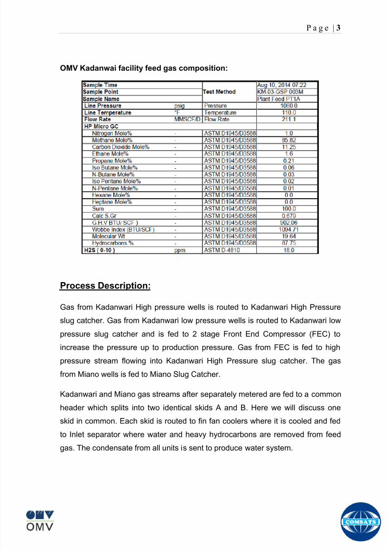
8102019 Gas sweetening Plant
httpslidepdfcomreaderfullgas-sweetening-plant 762
P a g e | 3
OMV Kadanwai facility feed gas composition
Process Description
Gas from Kadanwari High pressure wells is routed to Kadanwari High Pressure
slug catcher Gas from Kadanwari low pressure wells is routed to Kadanwari low
pressure slug catcher and is fed to 2 stage Front End Compressor (FEC) to
increase the pressure up to production pressure Gas from FEC is fed to high
pressure stream flowing into Kadanwari High Pressure slug catcher The gas
from Miano wells is fed to Miano Slug Catcher
Kadanwari and Miano gas streams after separately metered are fed to a common
header which splits into two identical skids A and B Here we will discuss one
skid in common Each skid is routed to fin fan coolers where it is cooled and fed
to Inlet separator where water and heavy hydrocarbons are removed from feed
gas The condensate from all units is sent to produce water system
8102019 Gas sweetening Plant
httpslidepdfcomreaderfullgas-sweetening-plant 862
P a g e | 4
The gas then passes through pretreatment skid which consists of following units
Feed Cooler
Feed Gas Scrubber
Filter Coalescer
Feed Gas Heater
Activated Carbon Guard Filter
Particle Filter
Its main function is to remove contaminants from gas such as dust lube oils
heavy hydrocarbons etc which may poison or reduce efficiency of membrane
unit
After pretreatment gas is fed to Molecular Sieve Absorbers (Memguard Units)
which ensures gas supplied to membranes is up to membrane standards of UOP
(vendor of membrane system) It removes all moisture and heavy hydrocarbons
from gas stream
Pretreated gas is now fed to the primary membranes The permeate stream (rich
in CO2) is sent to recycle membranes after passing through recycle compressor
and recycle pretreatment The permeate stream of recycle membranes is used as
regenerative medium for Memguard units and rest is sent to incinerator and
burnt The residual gas (rich in CH4) from primary membrane and recycle
membranes (all skids) is sent to H2S polishers via a common header
H2S polisher unit reduce the hydrogen sulfide level to the sales limit The gas is
now metered after compressing in sales gas compressor and is sent to SNGPL
trunk line after metering
Water is remove from condensate at produced water system by a three phase
separator The condensate is sold to refinery Major quantity is exported to
various industries
8102019 Gas sweetening Plant
httpslidepdfcomreaderfullgas-sweetening-plant 962
P a g e | 5
Figure Overall plant Process Flow Diagram
8102019 Gas sweetening Plant
httpslidepdfcomreaderfullgas-sweetening-plant 1062
P a g e | 6
Wellhead
A wellhead is the component at the surface of an oil or gas well that provides the
structural and pressure-containing interface for the drilling and production
equipment Its function is to maintain surface control of the well It forms a seal to
prevent well fluids from leaking or blowing at the surface They are rated for
working pressure of 2000 psi to 15000 psi (or greater)
When the well has been drilled and it is ready to provide an interface with the
reservoir rock and a tubular channel for the well fluids The surface pressure
control is provided by a Christmas tree which is installed on top of the wellhead
with valves and choke equipment to control the flow of well fluids during
production
Christmas tree
A Christmas tree is an assembly of valves spools and fittings used for an oil
well gas well water injection well gas injection well condensate well and other
types of wells
The primary function of a tree is to control the flow usually oil or gas out of the
well When the well and facilities are ready to produce and receive oil or gas tree
valves are opened and the formation fluids are allowed to go through a flow line
This leads to a processing facility A tree often provides numerous additional
functions including chemical injection points well intervention means pressure
relief means monitoring points (such as pressure temperature corrosion
erosion sand detection flow rate flow composition valve and choke position
feedback) and connection points for devices such as down hole pressure andtemperature transducers (DHPT) On producing wells chemicals or alcohols or
oil distillates may be injected to preclude production problems (such as
blockages)
The control system attached to the tree controls the down-hole safety valve
(SCSSV) while the tree acts as an attachment and means of the control system
to the down-hole safety valve
8102019 Gas sweetening Plant
httpslidepdfcomreaderfullgas-sweetening-plant 1162
P a g e | 7
Figure 1
Well Head and Christmas Tree
8102019 Gas sweetening Plant
httpslidepdfcomreaderfullgas-sweetening-plant 1262
P a g e | 8
Master Valves
The two lower valves are called the master valves Master valves are normally in
the fully open position and are never opened or closed when the well is flowing
(except in an emergency) to prevent erosion of the valve sealing surfaces They
are gate type valves
1 Lower Master Valve (LMV)
2 Upper Master Valve (UMV)
The lower master valve will normally be manually operated while the upper
master valve is often hydraulically actuated allowing it to be used as a means of
remotely shutting in the well in the event of emergency
Wing Valve
A wing valve is normally used to shut in the well when flowing thus preserving
the master valves for positive shut off for maintenance purposes The wing
valve can be a gate valve or ball valve Hydraulic operated wing valves are
usually built to be fail safe closed meaning they require active hydraulic pressure
to stay open This feature means that if control fluid fails the well will
automatically shut itself in without operator action
In Kadanwari well sites there is only one manually operated wing valve On the
other hand at Miano well sites there are two wing valves one being operated
manually and other hydraulically
Production Wing Valve
The right hand valve is often called the flow wing valve or the production wing
valve because it provides flow path for hydrocarbons to production facility
Kill wing valve
The left hand valve is often called the kill wing valve It is primarily used for
injection of fluids such as corrosion inhibitors or methanol to prevent hydrate
formation It is typically manually operated It can kill the well temporarily be
injection brine solution which provides a pressure head to well and temporarily
8102019 Gas sweetening Plant
httpslidepdfcomreaderfullgas-sweetening-plant 1362
P a g e | 9
suspends it for maintenance of well head Also it is used to permanently kill the
well A chemical is injected down the well that seals the piping down the well and
kills the well permanently
Swab valve
The swab valve is used to gain access to the well for wire line operations
intervention and other work over procedure On top of it is a tree adapter
and cap that will mate with various equipment For such operations a
lubricator is assembled up onto the top of the tree and the wire or coil is lowered
through the lubricator through swab valve and into the well This valve is typically
manually operated
Choke
A choke holds back pressure by restricting the flow opening at the well head This
is done to make better use of the gas for natural gas lift and to control the bottom-
hole pressure for recovery reasons
CHECK VALVE
The check is introduced in production flow line to prevent any reverse flow from
the line into the well It has a hinged flap which lifts to permit normal flow but
closes to prevent reverse flow
TOP ADAPTOR
The top adaptor is a fitting on top of the swab valve with a threaded connection
During normal well operations a pressure gauge is fitted to monitor flowing and
shut in wellhead pressures However during well service operations the cap can
be removed to allow installation of lubricators for wire-line operations
SCSSSV (Surface Control Sub Surface Safety Valve)
A subsurface safety valve is essentially a shutdown valve installed at the upper
wellbore for emergency shutdown to protect the production tubing and wellhead
in case of overpressure Subsurface safety valves can offer a barrier against flow
in the event of a wellhead collapse or other disastrous event Purpose of asubsurface safety valve (SSSV) is to avoid the ultimate disaster which can result
8102019 Gas sweetening Plant
httpslidepdfcomreaderfullgas-sweetening-plant 1462
P a g e | 10
in release of reservoir fluids to the surroundings This makes SSSV a very
important component of a well completion
A subsurface safety valve is typically a uni-directional flapper valve directed in
such a way that the flappers open downwards when pressure is applied from an
upward direction The flapper can only open in the downward direction So even if
high pressure is applied by the well fluids from a
downward direction a safety valve can remain
closed This makes a subsurface safety valve fail-
safe To open the valve hydraulic signal is sent from
the surface well control panel This hydraulic
pressure is responsible for keeping the flappers of
SSSV open and loss of hydraulic pressure result in
closing of the valve Thus wellbore can be isolated in
case of system failure or damage to the surface
facilities
Types of Christmas tree
There are two types of Christmas Tree
1 Solid block
2 Conventional
The solid block Christmas Tree has a central solid unit holding several valves
in a pre-constructed block Their advantage is the reduction in potential leak
paths and their higher pressure rating (Fig 2)
The conventional Christmas Tree is built up from individual valves bolted
together to form an assembly (Fig 3)
8102019 Gas sweetening Plant
httpslidepdfcomreaderfullgas-sweetening-plant 1562
P a g e | 11
Figure 2
Figure 3
8102019 Gas sweetening Plant
httpslidepdfcomreaderfullgas-sweetening-plant 1662
P a g e | 12
Wellhead Control Panel
Wellhead control panel is key equipment in oil amp gas industry to protect oilfield
facilities and environment from emergency incidents such as wellhead fire which
is one of main control systems to ensure oilfield oil production and transportation
to be safely operation according to international standards and national
regulation Wellhead control panel is composed of hydraulic power unit tubing amp
fitting and instrument valve and electrical control devices Hydraulic power unit
supply hydraulic resource to open and close safety valves including master
valves wing valves and SCSSSV
Its performs
Local OnOff SSV
Remote control SSV through RTU( remote terminal unit)
High-Low pressure sense shut-down automatically
Fusible Plug Anti-fire Shut-down automatically
Function of showing system pressure
Relief Valve shall be installed on each hydraulic circuit to prevent high
pressure
Function of showing hydraulic level and level switch for alarm
Function of defending pressure impact of system
Function of system pressure monitoring (by pressure transmitter of control
panel)
Function of remote emergency shut-down (by magnetic valve of control
panel)
Function of OnOff SSV monitoring (by pressure switch of control loop of
control panel)
8102019 Gas sweetening Plant
httpslidepdfcomreaderfullgas-sweetening-plant 1762
P a g e | 13
Chemical Injection
Chemical injection systems are commonly used in production facilities to prevent
or eliminate a wide range of problems that might negatively affect the production
flow It is done for flow assurance protection of process equipment such as
pipelines or to optimize processes in production facilities
Typical flow assurance chemicals are
Wax inhibitors
Pour point depressants
Asphaltene inhibitors
Corrosion inhibitors
A corrosion inhibitor is a chemical compound that is added to liquid or gas to
decreases the corrosion rate of a material typically a metal or an alloy The
effectiveness of a corrosion inhibitor depends on fluid composition quantity of
water and flow regime Its common mechanism involves formation of a coating
8102019 Gas sweetening Plant
httpslidepdfcomreaderfullgas-sweetening-plant 1862
P a g e | 14
which prevents access of the corrosive substance to the metal The corrosive
agents are generally oxygen hydrogen sulfide and carbon dioxide
At our production site the major risk is corrosion of piping and equipment The
maximum allowable corrosion rate is approximately 02 mm per year and
corrosion rate without inhibitor could be approximately 11 mm per year so the
corrosion protection program is designed to achieve a target corrosion rate of
less than 01 mm per year which is achieved by an inhibitor system efficiency of
99 Inhibitor is injected into the well stream flow through an atomizing nozzle
located downstream of the respective wellhead coolers at the duplexcarbon steel
interface In normal operation as per NALCO standards chemical (brand name
EC1144B) at rate of frac12 Liter per MMSCFD of gas is being injected into the flow
line of miano15 flow lines made of carbon steel Moreover the composition can
vary depending upon the composition of well fluids and material of pipeline This
method of injection ensures even distribution of the chemical on the interior
surface of the pipeline The individual well sites are equipped with Chemical
Injection Packages comprising of a stainless steel storage tank and two
pneumatic motor driven pumps in parallel Instrument gas is used to drive the
pumps Normally one pump is running with the other standby
Water Conning
Water coning is a term used to describe the mechanism underlying the upward
movement of water into the perforations of a producing well Coning can seriously
impact the well productivity and influence the degree of depletion and the overall
recovery efficiency of the reservoir The specific problems of water coning are
listed below
Costly added water handling
Gas production from the original or secondary gas cap reduces pressure
Reduced efficiency of the depletion mechanism
The water is often corrosive and its disposal costly
The affected well may be abandoned early
Loss of the total field overall recovery
8102019 Gas sweetening Plant
httpslidepdfcomreaderfullgas-sweetening-plant 1962
P a g e | 15
Therefore conning has an important influence on operations recovery and
economics The phenomena is shown in picture below
Corrosion
Corrosion is referred as chemical deterioration of a metal Commonly this
means loss of electrons of metals reacting with water and oxygen
Weakening of iron due to oxidation of the iron atoms is a well-known
example of electrochemical corrosion This is commonly known as
rust Most structural alloys corrode merely from exposure to moisture
in the air but the process can be strongly affected by exposure to
certain substances Corrosion can be concentrated locally to form a pit
or crack or it can extend across a wide area to produce general
deterioration (uniform corrosion)
The following reaction takes place at the active sites
2Fe =gt 2Fe++ + 4e-
The free electrons travel through the metal path to the less active sites where
the following reaction takes place
O2 + 4e- + 2H20 =gt 4 OH-
8102019 Gas sweetening Plant
httpslidepdfcomreaderfullgas-sweetening-plant 2062
P a g e | 16
Recombination of these ions at the active surface produce the following
reaction which yields the iron-corrosion product ferrous hydroxide
2Fe + O2 + 2H2O =gt 2Fe (OH) 2
CORROSION PROTECTION SYSTEM
Coatings and painting
Painting and the application of enamel bitumen and PVC
coating are the most common anti-corrosion treatments They
work by providing a barrier of corrosion-resistant material
between the damaging environment and the structural material
Corrosion Inhibitors
Corrosion inhibitor is injected into the flow lines as mentioned in
detail on page 8
Cathodic Protection
Cathodic Protection (CP) is a technique used to control the corrosion of a
metal surface by making it the cathode of an electrochemical cell It
converts all of the anodic (active) sites on the metal surface to cathodic
(passive) sites by supplying electrical current (or free electrons) from an
alternate source It is accomplished in two ways
a) A simple method of protection connects protected metal to a more easily
corroded sacrificial metal to act as the anode The sacrificial metal then
corrodes instead of the protected metal The process is similar to a simple
DC cell in which the more active metal becomes the anode and corrodes
whereas the less active metal becomes the cathode and is protected
b) For larger structures galvanic anodes cannot economically deliver enough
current to provide protection Therefore impressed current cathodic
protection (ICCP) systems are used These consist of anodes connected
to a DC power source In remote areas power sources such as solar
panels may be used The output DC negative terminal is connected to the
8102019 Gas sweetening Plant
httpslidepdfcomreaderfullgas-sweetening-plant 2162
8102019 Gas sweetening Plant
httpslidepdfcomreaderfullgas-sweetening-plant 2262
P a g e | 18
frequently to limit liquid holdup and minimize the slug volumes of liquid which can
be generated by the system
Coating
Pigs may be used to apply internal pipe coatings such as epoxy coating
materials in operating pipelines Pigs may also be used with corrosion inhibitors
to distribute and coat the entire internal wetted perimeter
Inspection
Pigs are being used more frequently as inspection tools Gauging or sizing pigs
are typically run following the completion of new construction or line repair to
determine if there are any internal obstacles bends or buckles in the pipe Pigs
can also be equipped with cameras to allow viewing of the pipe internals
Electronic intelligent or smart ldquopigsrdquo that use magnetic and ultrasonic systems
have been developed and refined that locate and measure internal and external
corrosion pitting dents buckles and any other anomalies in the pipe wall
Intelligent pigs
The accuracy of location and measurement of anomalies by the intelligent pigs
has continued to improve Initially the electronics and power systems were so
large that intelligent pigs could be used only in lines 30 in and greater in size
The continued sophistication and miniaturization of the electronic systems used
in the intelligent pigs has allowed the development of smaller pigs that can be
used in small-diameter pipelines Newly enacted DOT pipeline-integrity
regulations and rules acknowledge the effectiveness of the intelligent pigs and
incorporate their use in the pipeline-integrity testing process
Compressors
A gas compressor is a mechanical device that increases the pressure of a gas by
reducing its volume Gas pressure is increased by forcing gas molecules together
to reduce gas volume When volume is reduced gas pressure increases
All gases have large spaces among their molecules These spaces could be
enhanced further and decreased by doing some work Work done which is used
8102019 Gas sweetening Plant
httpslidepdfcomreaderfullgas-sweetening-plant 2362
P a g e | 19
for the enhancement of these spaces is called expansion and work done to
minimize these spaces is called compression All gases while expansion
produces cooling effect and while compression of gases raises there
temperature Compression is a term used to force gases to occupy smaller
volumes by increasing their pressure Volume of gases is interlinked with
temperature and pressure of the gas which is cleared by 2 laws govern gas
compressions
Boyles Law
Charles Law
The main types of compressor are listed below
Front End Compressor
The plant currently processes gas from a number of wells The flow and pressure
from some of these wells (currently K-10 K-11 amp K-12) has declined and they
cannot be fed directly into the Central Processing Facility To recover the
maximum gas reserves from these wells a Front End Compressor is employed
The compressor is a two stage double acting gas engine driven reciprocating
(PT) compressor Double acting means that gas is compressed on each end of
the piston It normal operates with a speed range of 600 to 900 RPM and isequipped with four compressor cylinders two for each stage Each cylinder is
8102019 Gas sweetening Plant
httpslidepdfcomreaderfullgas-sweetening-plant 2462
P a g e | 20
also equipped with a variable volume head end pocket
In case of compressor emergency shutdown the production chokes and the
Upper Master Valves on the on line wells will close and operator will be notified in
central control room Sweet gas from gas distribution network is used to operate the
gas engine driver of the compressor package The detailed scheme of working is
shown in figure (page 22 )
PT Reciprocating Compressor
The mechanical cycle of piston tube reciprocating compressor comprises four
strokes the expansion stroke the intake stroke the compression stroke and the
discharge stroke
Expansion Stroke
As the piston moves back on the expansion stroke the chamber volume
increases and the pressure drop As the pressure drops the discharge valve
closes since there is greater pressure in the discharge line than in the chamber
Intake Stroke
As the piston moves back during the intake stroke the pressure decreases until it
is less than the pressure in the inlet line This higher intake pressure opens the
inlet valve and gas rushes into the cylinder equalizing the pressure there with
the intake pressure The compression chamber is now at or near the intake
pressure
Compression Stroke
The piston now starts the compression stroke by moving forward decreasing the
chamber volume and increasing the pressure The increased pressure is now
higher than the intake pressure causing the intake valve to close
Discharge Stroke
The piston continues to move to the left during the discharge stroke This creates
an increase in chamber pressure until it is greater than the discharge pressure
When this happens the Discharge valve opens and the compressed air from the
8102019 Gas sweetening Plant
httpslidepdfcomreaderfullgas-sweetening-plant 2562
P a g e | 21
cylinder goes into the discharge line The compression cycle is then repeated
from the stage
Compressor Capacity
The capacity of the compressor depends upon cylinder displacement That
displacement is simply the volume that the piston displaces (moves) as it travels
from one end of the cylinder to the other Capacity and displacement is equal to
the cross-sectional area of the cylinder times the length of the stroke
Lubrication and Cooling
Lubricating oil is circulated through the system by a gear pump which is chain
driven from the engine crank shaft The oil pump is mounted on the engine front
housing
The pump operates between 30 - 40 psig
8102019 Gas sweetening Plant
httpslidepdfcomreaderfullgas-sweetening-plant 2662
P a g e | 22
A circulating pump deliver cooling water to the water jackets in the cylinder block
flowing around the cylinder liners and is directed into the cylinder heads Each
cylinder head has water cooled exhaust elbows which outlet the water into the
water cooled exhausts From the end of engine the water flows to compressor
1st and 2nd stage cylinders and compressor lube oil cooler (LOwater heat
exchanger) The water from the compressor cylinder and lube oil cooler returns
to engine water cooled exhaust
Figure Flow diagram of Front End Compressor
8102019 Gas sweetening Plant
httpslidepdfcomreaderfullgas-sweetening-plant 2762
P a g e | 23
Centrifugal Compressor
Centrifugal compressors are machines in which velocity and pressure given to air
or gas in a radial direction by one or more impellers diffuser combination In a
centrifugal compressor the mechanical energy is increased by centrifugal action
The gas enters the suction eye of a high speed rotary element called the impeller
which carries radial vanes integrally cast in it As the impeller rotates the blades
of the impeller force the gas outward from the center the impeller to the outer rim
of impeller the increase in velocity of the gas creates a flow pressure area at the
eye of the impeller The gas at the outer rim of the impeller is forced in to a
passage way called a diffuser where the velocity decreases in the pressure of the
gas
Inlet
The inlet to a centrifugal compressor is typically a simple pipe It may include
features such as a valve and both pressure and temperature instrumentation
Centrifugal impeller
The key component that makes a compressor centrifugal is the centrifugal
impeller shown above It is the impellers rotating set of vanes (or blades) that
gradually raises the energy of the working gas This is identical to an axial
compressor with the exception that the gases can reach higher velocities and
energy levels through the impellers increasing radius
8102019 Gas sweetening Plant
httpslidepdfcomreaderfullgas-sweetening-plant 2862
P a g e | 24
Diffuser
The next key component to the simple centrifugal compressor is the diffuser
Downstream of the impeller in the flow path it is the diffusers responsibility to
convert the kinetic energy (high velocity) of the gas into pressure by gradually
slowing (diffusing) the gas velocity
SEPERATORS
A well-stream is a mixture of gases hydrocarbon liquids water solids and
contaminants Due to variations in pressure and temperature gases evolve from
the liquids water vapor condenses and some of the well-stream changes to liquid
and free gas The separation of well-stream fluids takes place in a separator This
pressure vessel is manufactured in three forms
1 horizontal
2 vertical
3 spherical
To help separation the vessel is normally designed with a series of internal
fittings These fittings are built into the separator to ensure total phase separation
of the well-stream
In gas plants separators are given alternative names due to the function they
perform in the process system A scrubber does a similar job to a knockout drum
However the scrubber usually separates a stream containing high gas-to-liquid
ratios The knockout drum is used where a high degree of liquids are entrained in
the gas
Fluid flow from a well can include gas condensable liquid vapors water water
vapor crude oil and solids As well-stream fluids reach ground level where
pressure is lower than in the reservoir the capacity of the liquid to hold gas in
solution decreases and gas separates out of the oil
Separation depends upon the effect of gravity to separate liquids For adequate
separation one fluid must be lighter than the other fluid For example distillates
8102019 Gas sweetening Plant
httpslidepdfcomreaderfullgas-sweetening-plant 2962
P a g e | 25
(gasoline kerosene etc) and crude oil will not separate in a vessel because they
tend to dissolve in each other Because a separator basically depends upon
gravity to separate the fluids the ease with which separation takes place
depends upon the difference in density of the fluids
Droplets of liquid will separate from gas provided
a) The gas remains in the separator long enough
b) The gas flow remains constant to provoke separation
The difference in density between a gas and liquid will therefore determine the
maximum flow rate of liquid in the vessel
Figure Two phase horizontal separator
Gas bubbles in the liquid will break out in some oil field applications in 30 to 60
seconds Consequently the separator is designed so that the liquid remains in
the vessel for 30 to 60 seconds The length of time that a liquid remains in the
vessel is called its residence time Residence time differs widely from field to field
depending upon viscosity and API Gravity
Another important factor which must be considered is temperature Generally a
decrease in operating temperature will increase the liquid recovery in a separator
8102019 Gas sweetening Plant
httpslidepdfcomreaderfullgas-sweetening-plant 3062
P a g e | 26
as the gas condenses By reducing the pressure on the fluid flash separation
occurs resulting in a flow through the separator which is controlled by external
instrumentation
COALESCENCE
Another important principle in fluid separation is that of coalescence This means
the coming together of liquid droplets created by the force of gravity
A common example of coalescing occurs when drops of water form on the
windshield of a car as it is driven in fog As the tiny drops or water which make up
the fog strike the windshield they combine and eventually form a drop large
enough to run down the glass
Several of the internal devices of a separator such as deflector plates
straightening vanes and even the vessel walls are forms of coalescers In each
vessel drops of liquid adhere to the surface of the device and combine with other
8102019 Gas sweetening Plant
httpslidepdfcomreaderfullgas-sweetening-plant 3162
P a g e | 27
drops until the drop is large enough to fall out The effectiveness of separation
will also depend upon the total amount of coalescing surface area that is present
There are many different types of separators used in the Oil amp Gas industry
Consequently separators are manufactured with one two or several internal
fittings depending on their use and quick removal of these fluids from the vessel
DEFLECTOR PLATES
These are fitted in front of the inlet to the separator and can be net or
dish-shaped Their purpose is to absorb the impact of the incoming fluids and to
encourage the separation of gas and liquids They also slow the flow rate of the
liquids through the vessel
WEIRS
A weir is a metal wall which is fitted across the inside of the vessel normally to a
height of 50 of the overall height of the separator Its purpose is to assist the
process of three phase separation The inlet fluids (oil plus water) are given time
to separate in the liquid accumulation section The water level (interface) is
normally controlled at 50 of the height of the weir Oil floating on the wateroverflows the weir and accumulates in the small oil compartment where it is
drawn off under level control
CENTRIFUGAL DEVICES
These are used in both vertical and horizontal separators for gas-liquid
separation The device imparts a swirling motion to the fluids entering the vessel
Centrifugal force causes the heavier liquids to travel outwards towards the walls
of the vessel and the lighter gases to flow up the centre Centrifugal devices are
also known as cyclones
VORTEX BREAKERS
When liquid flows through a drain outlet a vortex (whirlpool) will form This can
be seen when we pull the plug from a sink or bath tub The same would happen
as water and oil flow from the separator This condition a vortex could allow gas
to flow down the centre of the whirlpool and enter the liquid phase causing
8102019 Gas sweetening Plant
httpslidepdfcomreaderfullgas-sweetening-plant 3262
P a g e | 28
pressurizing of tanks etc To stop this happening vortex breakers are fitted to all
liquid outlets Although they come in a number of different designs vortex
breakers all serve the same purpose - to prevent a whirlpool from forming
MIST OR DEMISTER PADS
The gas which is released from the fluids in the separator still contains droplets of
oil and water which coalesce and fall when the drops get large enough The
demister pad assists in this process Made from knitted wire and contained within
a sturdy frame it causes the gas to continually change its direction of flow
Because gas changes direction far easier than liquid the gas will flow around
each strand of wire whilst the liquid entrained in the gas stream will continue and
stick to the wire
COALESCING PLATES
There are several different forms of coalescing devices the most common of
which are coalescing plates These plates are mounted in the flow stream of the
fluids and assist in breaking down oil-water emulsions The fluid is forced to
follow a path that constantly changes direction This causes the water droplets to
gather together or coalesce and fall to the bottom of the separator The same
principle is used to separate gas and oil mixtures when the oil droplets are
induced to coalesce Simply stated every surface within the separator including
the separator walls assists with the coalescing process
STRAIGHTENlNG VANES
These are often fitted to horizontal separators to remove turbulence in the gas
stream after initial separation at the inlet deflector
FLOAT SHEILD
Internal floats are used as level controllers Any agitation of the liquid surface or
the effect of coalesced liquids falling on the float may cause control problems
Therefore a float shield is fitted to enclose the float creating an area of still liquid
8102019 Gas sweetening Plant
httpslidepdfcomreaderfullgas-sweetening-plant 3362
P a g e | 29
MEMBRANES
The gas contains 12 carbon dioxide and 22 ppm of hydrogen sulphide at 115oF
and 1100 psig This needs to be removed before the gas can be exported The
majority of carbon dioxide hydrogen sulphide and water is removed by means of
membranes
Membranes are thin semipermeable barriers that selectively separate some
compounds from others Currently the only commercially workable membranes
used for CO2 removal are polymer based for example cellulose acetate
polyimides polyamides polysulfone polycarbonates and polyetherimide The
membrane does not operate as a filter where small molecules are separated
from larger ones through a medium with pores rather it separates based on how
well different compounds dissolve into the membrane and diffuse through it The
membranes are manufactured in flat sheets consisting of an extremely thin
nonporous layer mounted on a much-thicker and highly porous layer of the same
material providing mechanical strength The flat sheets are combined into a
spiral-wound element (Figure below) Feed gas enters along the side of the
membrane and passes through the feed spacers As the gas travels between
membrane sheets CO2 H2S and H2O permeate through the membrane and are
collected in the permeate tube The driving force for transport is the high-feed
pressure and low-permeate pressures The gas on the feed side that does not
permeate leaves through the side of the element opposite the feed position Once
the membranes have been manufactured into elements six to 12 elements are
joined together and inserted into a tube Multiple tubes are mounted on skids in a
horizontal orientation
8102019 Gas sweetening Plant
httpslidepdfcomreaderfullgas-sweetening-plant 3462
P a g e | 30
Figure Membrane general Working
In high H2S applications most polymers have been shown to have very little
resistance to H2S plasticization (ldquosofteningrdquo of the membrane) and as a
consequence can only be used at very low H2S partial pressure limits Cellulose
acetate membranes in contrast have been shown to be applicable at extreme
H2S partial pressure conditions It is these membranes that have been utilized in
the testing to determine the limits of membrane performance in high H 2S
applications
The primary membranes used in Kadanwari facility are Cellulose acetate
Cellulose acetic acid and acetic anhydride are mixed together and reacted to
form cellulose acetate polymers This process is aided by the addition of a small
amount of sulfuric acid which is subsequently neutralized during processing
However the membranes are bought from UOP (vendor) and installed for use
8102019 Gas sweetening Plant
httpslidepdfcomreaderfullgas-sweetening-plant 3562
P a g e | 31
How membrane work
The basic principle of separation is selectivity of certain components of a mixture
for the membrane For example the cellulose acetate membrane has very high
selectivity for CO2 and H2S as compared to CH4 Therefore such type of
membrane can be used in gas sweetening process
The selectivity is directly related to the Permeability of gas which accounts that
which gas can pass across the membrane more easily In simple words
membranes being polymer materials are made of long chains of molecules The
different structure of polymer materials only allow selective molecules to pass
through them depending upon chemical and physical compatibility Thus
permeability depends upon choice of polymer
The permeability is determined by permeability coefficient (P) and is product of
solubility (S) and diffusivity (D)
P = S D
Solubility
The solubility is mainly determined by ease of condensation Heavy molecules
are more readily condensed Therefore higher molecular weighted molecules will
more easily condensed and therefore have greater solubility
Molecule Molecular weight
CH4 16
H2S 34
CO2 44
8102019 Gas sweetening Plant
httpslidepdfcomreaderfullgas-sweetening-plant 3662
P a g e | 32
Diffusivity
Diffusivity is ease of molecule to penetrate into some material It depends on size
of gas molecule Here size of molecule is not to be confused by molecular weight
it is the size of the structure Eg the size of O2 molecule is smaller than N2
Molecule Molecular Diameter (Ao)
CO2 33
H2S 36
Ch4 40
For cellulose acetate
DCO2DCH4 S CO2S CH4 P CO2P CH4
45 73 308
Chemical degradation
Cellulose acetate polymer is chemically degraded by a process called hydrolysis
which means breaking apart by the addition of water This is a chemical reaction
in which water is added to the cellulose acetate polymer causing the release of
acetic acid molecules This process proceeds stepwise until all the acetate
groups are released resulting in the reformation of cellulose Moreover alcohols
aromatic hydrocarbons or solvents with chlorine nitro benzene or similar
aromatic solvents will harm the membrane It will expand and lose plastification in
contact with them
Effect of Temperature
The permeation rates of all gases increases with increasing temperature
however membrane selectivity for CO2 over hydrocarbon decreases at higher
8102019 Gas sweetening Plant
httpslidepdfcomreaderfullgas-sweetening-plant 3762
P a g e | 33
temperature Consequently CO2 removal will improve as operating temperature
increases but hydro carbon recovery will decrease
Primary Membrane
The primary membranes comprise of two trains Each train consists of two
sections AB and CD each section consists of a 30 tube membrane skid (A and
C) followed by a 25 tube skid (B and D) The conditioned gas (after pre-
treatment) enters the primary membrane via the particulate filter adjacent to the
skid The gas is fed to the membranes through a common inlet manifold which
supplies primary membranes skids A and C A pressure control loop located
upstream of the manual inlet isolation valve is provided to maintain a constant
supply pressure to the membrane skid and to allow for preheating at the inlet
prior to skid start-up This pressure control loop can also be used during start-up
to control the pressurization of the pretreatment skid and associated pipes to the
primary membranes
The gas passes through membrane skid A the residual gas exiting the membrane
skid is sent to skid B and the permeate to common permeate discharge header An
identical arrangement is provide on the inlet to skid C as provided on skid A Theresidual gas from skid B combines with the residual gas from skid D in a common
discharge header and is then sent to the H2S polishing towers via the feed coolers
on the pre-treatment skid The permeate from skid B is sent to the common
permeate discharge header The permeate discharge header sends the gas to
either the recycle compressor or the vent header via a pressure control loop
Overpressure protection for the membranes is provided by a pressure safety valve
on the supply header to the membrane banks
8102019 Gas sweetening Plant
httpslidepdfcomreaderfullgas-sweetening-plant 3862
P a g e | 34
Secondary (Recycle) Membrane
The recycle membranes comprise of a single train with two skids each with four
banks of membrane tubes The conditioned gas from the discharge of the recycle
pre-treatment skid is routed to the first recycle membrane skid The gas passes
through the membranes the residual gas is fed to primary membrane (skid A) inlet
via feed gas cooler and permeate to the common permeate discharge header An
identical arrangement is provide on the inlet to skid B Permeate from the recycle
membrane skids A and B is routed to the vent header Some portion of permeate is
heated and sent for regeneration in Mem-Guard units Nitrogen purge can be
connected downstream of the inlet isolation valve on each skid to enable the
membrane tubes to be purged and left pressurized during prolonged shutdown
8102019 Gas sweetening Plant
httpslidepdfcomreaderfullgas-sweetening-plant 3962
P a g e | 35
Figure Flow Diagram of Recycle membrane unit
8102019 Gas sweetening Plant
httpslidepdfcomreaderfullgas-sweetening-plant 4062
P a g e | 36
ADVANTAGES OF MEMBRANE SYSTEMS
Membrane systems have major advantages over more-traditional methods of
acid gas removal
Lower capital cost Membrane systems are skid mounted and so the
scope cost and time taken for site preparation are minimal Installation
costs are significantly lower than alternative technologies especially for
remote areas Furthermore no additional facilities for solvent storage and
water treatment needed by other processes are required
Lower operating costs The only major operating cost for single-stage
membrane systems is membrane replacement This cost is significantly
lower than the solvent replacement and energy costs associated with
traditional technologies The improvements in membrane and
pretreatment design allow a longer useful membrane life which further
reduces operating costs The energy costs of multistage systems with
large recycle compressors are usually comparable to those for traditionaltechnologies
Deferred capital investment Often contracted sales-gas flow rates
increase over time as more wells are brought on-line With traditional
technologies the system design needs to take this later production into
account immediately and so the majority of the equipment is installed
before it is even needed The modular nature of membrane systems
means that only the membranes that are needed at start-up need be
installed The rest can be added either into existing tubes or in new skids
only when they are required
Operational simplicity and high reliability Because single-stage
membrane systems have no moving parts they have almost no
8102019 Gas sweetening Plant
httpslidepdfcomreaderfullgas-sweetening-plant 4162
P a g e | 37
unscheduled downtime and are extremely simple to operate They can
operate unattended for long periods of time The addition of a recycle
compressor adds some complexity to the system but still much less than
with a solvent- or adsorbent-based technology Multistage systems can be
operated at full capacity as single-stage systems when the recycle
compressor is down
Good weight and space efficiency Skid construction can be optimized
to the space available This space efficiency is especially important for
offshore environments where deck area is at a premium and is the
reason why so many new offshore developments have chosen to use
membranes for acid gas removal Figure 6 illustrates the space efficiency
of membrane systems The membrane unit in the lower left corner
replaced all the amine and glycol plant equipment shown in the rest of the
picture
Adaptability Because membrane area is dictated by the percentage of
acid gas removal rather than absolute acid gas removal small variations
in feed acid gas content hardly change the sales-gas acid gas
specification For example a system designed for 10 down to 3 acid
gas removal produces a 35 product from a 12 feed gas and a 5
product from a 15 feed gas
Design efficiency The membrane and pretreatment systems integrate a
number of operations such as dehydration CO2 and H2S removal dew-
point control and mercury removal Traditional acid gas removal
technologies require all of these operations as separate processes and
may also require additional dehydration because some technologies
saturate the product stream with water
8102019 Gas sweetening Plant
httpslidepdfcomreaderfullgas-sweetening-plant 4262
P a g e | 38
Power generation The permeate gas from membrane systems can be
used to provide fuel gas for power generation either for a recycle
compressor or other equipment
Ideal for debottlenecking Because expanding solvent- or adsorbent-
based acid gas removal plants without adding additional trains is difficult
an ideal solution is to use membranes for bulk acid gas removal and leave
the existing plant for final cleanup An additional advantage is that the
permeate gas from the membrane system can often be used as fuel for
the existing plant thus avoiding significant increase in hydrocarbon
losses
Environmentally friendly Membrane systems do not involve the
periodic removal and handling of spent solvents or adsorbents Permeate
gases can be flared used as fuel or re-injected into the well Items thatdo need disposal such as spent membrane elements can be incinerated
Ideal for remote locations Many of the factors mentioned above make
membrane systems a highly desirable technology for remote locations
where spare parts are rare and labor unskilled Furthermore solvents
storage and trucking water supply power generation or extensive
infrastructure are not required
Re-injection optimizations Since the permeate stream from the
membrane system can be operated at elevated pressures it is possible to
further pressurize by re-injection compression train
8102019 Gas sweetening Plant
httpslidepdfcomreaderfullgas-sweetening-plant 4362
P a g e | 39
Sorption
Sorption is a physical and chemical process by which one substance becomes
attached to another
It is of two main types
1 Absorption
2 Adsorption
Absorption
Absorption is a physical or chemical phenomenon or process in which atoms
molecules or ions enter some bulk phase ndash gas liquid or solid material This is a
different process from adsorption since molecules undergoing absorption are
taken up by the volume not by the surface (as in the case for adsorption)
Absorption process may be chemical (reactive) or physical (non-reactive)
Physical absorption
Physical absorption or non-reactive absorption is made between two phases ofmatter a liquid absorbs a gas or a solid absorbs a liquid
When a liquid solvent absorbs a gas mixture or part of it a mass of gas moves
into the liquid For example water may absorb oxygen from the air This mass
transfer takes place at the interface between the liquid and the gas at a rate
depending on both the gas and the liquid This type of absorption depends on the
solubility of gases the pressure and the temperature The rate and amount of
absorption also depend on the surface area of the interface and its duration in
time
When a solid absorbs a liquid mixture or part of it a mass of liquid moves into the
solid For example a clay pot used to store water may absorb some of the water
This mass transfer takes place at the interface between the solid and the liquid
at a rate depending on both the solid and the liquid
8102019 Gas sweetening Plant
httpslidepdfcomreaderfullgas-sweetening-plant 4462
P a g e | 40
Chemical absorption
Chemical absorption or reactive absorption is a chemical reaction between the
absorbed and the absorbing substances Sometimes it combines with physical
absorption This type of absorption depends upon the stoichiometry of the
reaction and the concentration of its reactants
Adsorption
Adsorption is the adhesion of atoms ions or molecules from a gas liquid or
dissolved solid to a surface This process creates a film of the adsorbate on the
surface of the adsorbent The binding to the surface is usually weak and
reversible Compounds with color and those that have taste or odor tend to bind
strongly Compounds that vibrate at frequencies in the visible spectrum are very
often are strongly adsorbed on activated carbon
The most common industrial adsorbents are activated carbon silica gel and
alumina because they present enormous surface areas per unit weight
Depending on the nature of attractive forces existing between the adsorbate and
adsorbent adsorption can be classified as
i) Physical adsorption
ii) Chemical adsorption
i) Physical adsorption (Physisorption)
In physical adsorption the forces of attraction between the molecules of the
adsorbate and the adsorbent are of the weak van der Waals type Since the
forces of attraction are weak the process of physisorption can be easily reversed
by heating or decreasing the pressure of the adsorbate (as in the case of gases)
8102019 Gas sweetening Plant
httpslidepdfcomreaderfullgas-sweetening-plant 4562
P a g e | 41
ii) Chemical adsorption (Chemisorption)
In chemisorption the forces of attraction between the adsorbate and the
adsorbent are very strong the molecules of adsorbate form chemical bonds with
the molecules of the adsorbent present in the surface
Adsorption is generally accompanied by release of energy that is most
adsorption processes are exothermic in nature Adsorption is a spontaneous
process therefore its free energy change is negative (∆Glt0) However the
entropy change associated with adsorption is generally negative because the
adsorbate molecules lose their translation freedom when they get attached to the
surface of the adsorbent Therefore in order for ∆G to be negative the enthalpy
change (∆H) must be sufficiently negative such that (∆G=∆H-T∆S) lt 0 This
explanation accounts for exothermic adsorption processes In cases where
endothermic adsorption occurs the entropy change ∆S is sufficiently positive
such that ∆G remains negative
Pre treatment
The main function of pretreatment skid is to provide membrane inlet specification
gas as mentioned by the vendor UOP It removes the contaminants that would
poison the membranes like dust solids (adsorbent particles) lube oil heavy
hydrocarbons etc It consists of
Feed Cooler
Feed Gas Scrubber
Filter Coalescer
Feed Gas Heater
Activated Carbon Guard Filter
Particle Filter
8102019 Gas sweetening Plant
httpslidepdfcomreaderfullgas-sweetening-plant 4662
8102019 Gas sweetening Plant
httpslidepdfcomreaderfullgas-sweetening-plant 4762
P a g e | 43
The regeneration is carried out by heated permeate gas from the recycle
membranes at 450oF The vessel is depressurized to 20 psi and heated gas is
introduced from top The gas carries out the adsorbed contaminants and leaves
the vessel from bottom cleaning the adsorbent This contaminated gas is burnt in
the flare
UOP the vendor of Memguard unit has never disclosed that what substance
MG3 and MG5 exactly are But as mentioned by vendor that both care class of
aluminosilicates Therefore MG3 can be potassium aluminosilicate and MG5 can
be Calcium aluminosilicate These are molecular sieves adsorbents Molecular
sieves are a microporous material which can selectively adsorb gases andliquids They are synthetic zeolites (crystalline metal aluminosilicates) which
upon dehydration can efficiently and selectively remove water or other
solvents The selectivity of a molecular sieve is determined by its pore size
molecules with a critical diameter which is less than the pore size will be
efficiently adsorbed while larger molecules will be excluded
8102019 Gas sweetening Plant
httpslidepdfcomreaderfullgas-sweetening-plant 4862
P a g e | 44
3A Molecular Sieve Adsorbent
The 3A molecular sieve adsorbent has a 3 angstrom (3A) pore size which means
that any molecule that is larger than the 3 angstrom pores will not be adsorbed
The 3A molecular sieve is the potassium type of A crystalline structure and is a
form of alkali Aluminosilicate For a 3A molecular sieve the sequence rate that
adsorption occurs is He Ne N and H2O
Due to the crystalline structure molecular sieves that have a 3 angstrom pore
size have a very high rate of adsorption and properties that promote a longer life
for products treated by the sieve The most common use for the 3A molecular
sieve is to remove water and moisture from materials that are in gas and liquid
form
5A Molecular Sieve Adsorbent
These are molecular sieve adsorbents with a pore size of 5 angstrom (5A) 5A
molecular sieves are unable to adsorb any molecules or impurities that are
smaller than 5A It is calcium form of type A crystalline structure and is form of analkali-aluminosilicate that is most commonly used to separate isomerous alkanes
from normal alkanes and to co-adsorb moisture and water along with carbon
dioxide from gases In additional 5A molecular sieves are used for gaseous
pressure swing adsorption (PSA)mdashthat is to separate particular gases from other
gases
Adsorption of nC4H10
Adsorption of nC4H10
Adsorption of C3H8 to C22H46
Adsorption of Freon-12 (dichlorodifluoromethane)
Natural gas drying
Normal- and iso-paraffin separation
Separation of aromatic
8102019 Gas sweetening Plant
httpslidepdfcomreaderfullgas-sweetening-plant 4962
P a g e | 45
Inlet Composition of Memguard vessel
COMPSOSITION MOLE
CARBON DIOXIDE 1096
MEHTANE 8593
ETHANE 173
PROPANE 023
I-BUTANE 008
N BUTANE 004
PENTANES 004
HEXANE + 000
NITROGEN 076
WATER 007
Outlet Composition of Memguard vessel
COMPSOSITION MOLE
CARBON DIOXIDE 1098
MEHTANE 8608
ETHANE 173
PROPANE 023
I-BUTANE 008N BUTANE 004
PENTANES 004
HEXANE + 000
NITROGENT 076
WATER 000
H2S polisher
The H2S polishing unit has been designed to treat 187 MMscfday of natural gas
containing up to 11 CO2 and 21 ppm H2S where the level of the CO2 and H2S
is reduced using a MemGuard Membrane separation unit The unit is situated
down-stream of the membrane unit and will further reduce the level of H2S in the
processed gas to a sales gas specification of 38 ppm
8102019 Gas sweetening Plant
httpslidepdfcomreaderfullgas-sweetening-plant 5062
P a g e | 46
This process uses three non-regenerable fixed bed absorber vessels using a low
temperature high activity absorbent The absorbent is a mixture of activated
metal oxides (mainly zinc oxide) The three towers can are generally operated in
parallel arrangement but on demand can be used in series (any of alternate
arrangements of A B C vessels) as shown in figure
The higher sales gas flow rate increased the catalyst consumption and
replacement frequency
ZnO + H2S =gt ZnS + H20
Routine samples are taken from the beds to provide a check on each bed
performance and to follow the saturation profile during the absorbent life After
the adsorbent has been fully utilized the adsorption vessels are recharged with
new adsorbent discarding the utilized one in a safe manner
109oF
1215 psig
Before H2S Polishing After H2S Polishing
8102019 Gas sweetening Plant
httpslidepdfcomreaderfullgas-sweetening-plant 5162
P a g e | 47
Figure
H2S Tower
Inlet pipe
4 Drums of 19mm
ceramic Balls
6 Micron mesh
5 Drums of 50mmceramic
1 Drums of19mm ceramic
01 Drums of6mm ceramic
112 drums of
Catalist ZnO
8102019 Gas sweetening Plant
httpslidepdfcomreaderfullgas-sweetening-plant 5262
P a g e | 48
Recycle Compressor
The permeate gas of the primary membrane unit carries recoverable amount of
CH4 It is fed to recycle membrane unit for further CH 4 recovery But the
permeate pressure from primary membranes which has been reduced to 12 psi
must be regenerated to 1200 psi for the gas to be fed again to the system For
this purpose we have employed recycle compressor The compressor is a four
stage centrifugal compressor It is driven by gas turbine of 31200 HP It has 25
MW producing capacity
Figure Recycle Compressor Process Flow Diagram
8102019 Gas sweetening Plant
httpslidepdfcomreaderfullgas-sweetening-plant 5362
P a g e | 49
Sales Gas Compressor
Gas from H2S polishing unit is sent to sales gas compressor where its pressure
is enhanced to 1100 psi so it may be injected to SNGPL high pressure trunk line
Sales gas compressor is single stage gas turbine driven
Figure Process Flow of Sales Gas Compressor
8102019 Gas sweetening Plant
httpslidepdfcomreaderfullgas-sweetening-plant 5462
P a g e | 50
Cooling Towers
A cooling tower is a heat rejection device which extracts waste heat to theatmosphere through the cooling of a water stream to a lower temperature Hot
water from the system enters the cooling tower and is distributed over the fill
(heat transfer surface) Air is induced or forced through the fill causing a small
portion of the water to evaporate This evaporation removes heat from the
remaining water which is collected in the cold water basin and returned to the
system to absorb more heat Each cooling tower line although operating under
the same basic principle of operation is arranged a little differently
Types
Natural draft mdash Utilizes buoyancy via a tall chimney Warm moist air naturally
rises due to the density differential compared to the dry cooler outside air Warm
moist air is less dense than drier air at the same pressure This moist air
buoyancy produces an upwards current of air through the tower
Mechanical draft mdash Uses power-driven fan motors to force or draw airthrough the tower
o Induced draft mdash A mechanical draft tower with a fan at the
discharge (at the top) which pulls air up through the tower The fan
induces hot moist air out the discharge This produces low entering
and high exiting air velocities reducing the possibility of
recirculation in which discharged air flows back into the air intake
o Forced draft mdash A mechanical draft tower with a blower type fan at
the intake The fan forces air into the tower creating high entering
and low exiting air velocities The low exiting velocity is much more
susceptible to recirculation This fanfill geometry is also known as
blow-through
8102019 Gas sweetening Plant
httpslidepdfcomreaderfullgas-sweetening-plant 5562
P a g e | 51
Forced Draft Cooling Tower Vs Induced Draft Cooling Tower
Induced Draft Cooling Tower have the ability to handle large water flow
rate than Forced Draft Cooling Tower
Induced Draft Cooling Tower is suitable for large cell sizes and fan sizes
as compared with Forced Draft Larger fan size may result in greater
efficiency and consequently lower power and sound level
Forced Draft Cooling Tower can be square or rectangular type only
however Induced Draft Cooling Towers can be round square or
rectangular type
Induced Draft Cooling Tower uses more compact ground area than Forced
Draft Cooling Tower equivalent capacity due to absence of fan on one
side
Fan equipment is warm exhaust air is less liable to icing up in winter
operation (Cold Countries)
Higher velocity in Forced Draft Cooling Tower cause drop in suspension
and cause additional static resistance to system
Configuration
There are two main configurations of factory assembled cooling towers crossflow
and counterflow In crossflow cooling towers the water flows vertically down the
fill as air flows horizontally across In counterflow cooling towers the water flows
vertically down the fill as air flows vertically up
Crossflow Configuration Counterflow Configuration
8102019 Gas sweetening Plant
httpslidepdfcomreaderfullgas-sweetening-plant 5662
P a g e | 52
Drift mdash Water droplets that are carried out of the cooling tower with the exhaust
air Drift droplets have the same concentration of impurities as the water entering
the tower The drift rate is typically reduced by employing baffle-like devices
called drift eliminators through which the air must travel after leaving the fill and
spray zones of the tower
Blow-out mdash Water droplets blown out of the cooling tower by wind generally at
the air inlet openings Water may also be lost in the absence of wind through
splashing or misting Devices such as wind screens louvers splash deflectors
and water diverters are used to limit these losses
Blow-down mdash The portion of the circulating water flow that is removed (usually
discharged to a drain) in order to maintain the amount of Total Dissolved Solids
(TDS) and other impurities at an acceptably low level Higher TDS concentration
in solution may result from greater cooling tower efficiency However the higher
the TDS concentration the greater the risk of scale biological growth and
corrosion
Make-up mdash The water that must be added to the circulating water system in
order to compensate for water losses such as evaporation drift loss blow-out
blow-down etc
Approach mdash The approach is the difference in temperature between the cooled-
water temperature and the entering-air wet bulb temperature
Range mdash The range is the temperature difference between the warm water inlet
and cooled water exit
Fill mdash Inside the tower fills are added to increase contact surface as well as
contact time between air and water to provide better heat transfer The efficiency
of the tower depends on the selection and amount of fill
8102019 Gas sweetening Plant
httpslidepdfcomreaderfullgas-sweetening-plant 5762
P a g e | 53
There are two types of fills that may be used
o Film type fill (causes water to spread into a thin film)
o Splash type fill (breaks up falling stream of water and interrupts its
vertical progress)
Important
Scale build up is controlled by adding chemicals to the cooling loop and diluting
the concentration by blow down and make-up Following chemicals are added to
the Cooling to control CorrosionSale and microbial growth
Corrosion Inhibitor To control corrosion in the Cooling system
Dispersant To kept ions in suspension to avoid settle down and buildup
Sodium hypo Chlorite To Control microbial Growth
Acid To control Alkalinity in the system
High Stress Polymer To run the system at higher conductivity It is a
multifunctional polymer for Zinc amp Phosphate stabilization in cooling tower
Fin Fan Cooler
Fin fan heat exchanger is simply a pressure vessel which cools a circulating fluid
within finned tubes by forcing ambient air over the exterior of the tubes A
common example of an air cooler is a carrsquos radiator Fin Fan Coolers are used in
any application where large quantities of heat need to be transferred This
includes chemical and petrochemical industries power stations waste-to-energy
facilities as well as steelworks
Fin Fan Cooler are used for two primary reasons
They increase plant efficiency
They are a green solution as compared to cooling towers and shell and
tube heat exchangers because they do not require an auxiliary water
8102019 Gas sweetening Plant
httpslidepdfcomreaderfullgas-sweetening-plant 5862
P a g e | 54
supply (water lost due to drift and evaporation plus no water treatment
chemicals are required)
Figure General Overview of Fin Fan Cooler
Produced Water
The produced water system receives liquid from the equipment Miano slug
catcher train 1 and 2 inlet separators and is fed to three phase separator where
water oil and gas is separated The gases produced are burnt in incinerator
whereas hydrocarbon liquid is stored to be sold Liquid from compressors
recycle inlet separator recycle feed scrubber high and low pressure slug
catchers is passed to degasser Separated water is injected down the earth
Incinerator
The term incinerate means to burn something until nothing is left but ashes An
incinerator is a unit or facility used to burn trash and other types of waste until it is
reduced to ash An incinerator is constructed of heavy well-insulated materials
so that it does not give off extreme amounts of external heat The high levels of
heat are kept inside the furnace or unit so that the waste is burned quickly and
efficiently If the heat were allowed to escape the waste would not burn as
completely or as rapidly
8102019 Gas sweetening Plant
httpslidepdfcomreaderfullgas-sweetening-plant 5962
P a g e | 55
Control System
The plant is controlled at CCR (Central Control Room) by PLCs (Programmable
Logic Controllers) through fiber optic control line All control parameters are
received at LER (Local Equipment Room) via two optic fiber control lines One
being primary and other secondary operating in redundancy ie if primary fails
control shifts to secondary These control parameters are sent to CCR via single
optic fiber cable
Safety System
Wellheads and Gas Processing Plant have their own Fire amp Gas detection
systems emergency shutdown (ESD) Plant has a fault tolerant controller It is
based on Triple Modular Redundant (TMR) architecture manufactured by
Triconex The TMR system is based on three isolated parallel control systems
integrated into one system The system operates on a two out of three voting
principle which provides high integrity error free uninterrupted operation with no
single point of failure The TMR receives inputs from Process Sensors Manual
Switches Fire amp Gas Detectors Packaged Equipment Control Systems and
Product Exporting Facilities The TMR carries out cause and effect processing on
the data received and where necessary produces output signals Outputs from
the TMR are hard wired directly to ESD shutdown and blow down valve
solenoids motor control instrumentelectrical interfaces to control electrical
drives package equipment logic control systems manifold area as well as
telecoms
The operator in central control room is able to accept alarms and once the fault
has been cleared reset the input All the control systems are centralized to a
single interface All the PLCs (Programmable Logic Controllers) communicate with
the servers and servers communicate with the clients through Ethernet connectivity
Centralization eases the navigation of different systems at a common interface
Emergency Shutdown
The ESD system receives inputs from field mounted instrumentation on the process
8102019 Gas sweetening Plant
httpslidepdfcomreaderfullgas-sweetening-plant 6062
P a g e | 56
and utility equipment and initiates executive actions appropriate to the level of ESD
The system is an Active system which is in standby and will activate when in an
alarm or fault condition The Kadanwari Gas Process Facility ESD system is
comprised of five (5) levels The emergency severity decreases with increasing ESD
level number
ESD 1
This shutdown level is automatically initiated by fire major gas leak or a detected
toxic atmosphere in the process area of the plant or manually from CCR A level 1
shutdown will cause all production to cease close all emergency shutdown
valves stop the process and shutdown of the main power generation The
emergency vent valves to the stack will open and in addition all equipment of zone 1
certified will be isolated This is the highest level of ESD and will cause the following
to occur
All Shutdown Valves (SDVs) on the process facility will close All slowdown Valves (BDVs) on the process facility will open
All Main Gas Driven Generators will be tripped
Emergency Diesel Generator will start
All electrical power to process and utility rotating equipment will be
isolated
Wellhead Choke Valves Close Wing Valves Close Upper Master Valve
(UMV) Close
ESD 2
This shutdown level is activated automatically if a major process or utility failure
occurs or manually from CCR All production to the plant from the wellhead is
stopped All emergency shutdown valves trip to their fail safe position
Venting shall be as specified This level of ESD will cause the following to occur
8102019 Gas sweetening Plant
httpslidepdfcomreaderfullgas-sweetening-plant 6162
P a g e | 57
All Shutdown Valves (SDVs) on the process facility will close
All electrical power to process and utility rotating equipment will be
isolated
Wellhead Choke Valve Close Wing Valves Close and Upper Master Valve(UMV) Close
ESD 3
The level 3 shutdown isolates and stops a single process train only Production
continues via the other train This ESD level is initiated by process conditions or
operator at local panel This level of ESD will cause the following to occur
ESD 3A Train 1 production to cease
ESD 3B Train 2 production to cease
All online wellhead choke valves go to minimum flow ie (1O )
ESD 4
A level 4 shutdown shall cease all production from an entire field either
Kadanwari or Miano upstream of the associated slug catchers ESD 4K for
Kadanwari amp ESD 4M for Miano This ESD level is initiated automatically by slug
catcher abnormal process conditions This level of ESD will cause the following
to occur
All SDVs close isolating the relevant slug catcher and its upstream gas
production facility from the Kadanwari Gas Processing Plant
All Wellhead Choke Valves Close Wing Valves Close and Upper MasterValves (UMV) of the relevant gas production facility Close
A parallel timer is provided to close within 10 second if not closed in given
time SSSV seals the well
ESD 5
A level 5 shutdown represents equipment shutdown for the protection of the
individual equipment without any change in the process This level of ESD is for the
protection of various pieces of equipment and is initiated by its own inputs eg
8102019 Gas sweetening Plant
httpslidepdfcomreaderfullgas-sweetening-plant 6262
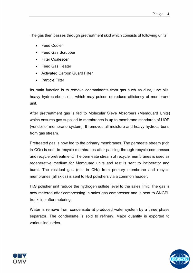
8102019 Gas sweetening Plant
httpslidepdfcomreaderfullgas-sweetening-plant 862
P a g e | 4
The gas then passes through pretreatment skid which consists of following units
Feed Cooler
Feed Gas Scrubber
Filter Coalescer
Feed Gas Heater
Activated Carbon Guard Filter
Particle Filter
Its main function is to remove contaminants from gas such as dust lube oils
heavy hydrocarbons etc which may poison or reduce efficiency of membrane
unit
After pretreatment gas is fed to Molecular Sieve Absorbers (Memguard Units)
which ensures gas supplied to membranes is up to membrane standards of UOP
(vendor of membrane system) It removes all moisture and heavy hydrocarbons
from gas stream
Pretreated gas is now fed to the primary membranes The permeate stream (rich
in CO2) is sent to recycle membranes after passing through recycle compressor
and recycle pretreatment The permeate stream of recycle membranes is used as
regenerative medium for Memguard units and rest is sent to incinerator and
burnt The residual gas (rich in CH4) from primary membrane and recycle
membranes (all skids) is sent to H2S polishers via a common header
H2S polisher unit reduce the hydrogen sulfide level to the sales limit The gas is
now metered after compressing in sales gas compressor and is sent to SNGPL
trunk line after metering
Water is remove from condensate at produced water system by a three phase
separator The condensate is sold to refinery Major quantity is exported to
various industries
8102019 Gas sweetening Plant
httpslidepdfcomreaderfullgas-sweetening-plant 962
P a g e | 5
Figure Overall plant Process Flow Diagram
8102019 Gas sweetening Plant
httpslidepdfcomreaderfullgas-sweetening-plant 1062
P a g e | 6
Wellhead
A wellhead is the component at the surface of an oil or gas well that provides the
structural and pressure-containing interface for the drilling and production
equipment Its function is to maintain surface control of the well It forms a seal to
prevent well fluids from leaking or blowing at the surface They are rated for
working pressure of 2000 psi to 15000 psi (or greater)
When the well has been drilled and it is ready to provide an interface with the
reservoir rock and a tubular channel for the well fluids The surface pressure
control is provided by a Christmas tree which is installed on top of the wellhead
with valves and choke equipment to control the flow of well fluids during
production
Christmas tree
A Christmas tree is an assembly of valves spools and fittings used for an oil
well gas well water injection well gas injection well condensate well and other
types of wells
The primary function of a tree is to control the flow usually oil or gas out of the
well When the well and facilities are ready to produce and receive oil or gas tree
valves are opened and the formation fluids are allowed to go through a flow line
This leads to a processing facility A tree often provides numerous additional
functions including chemical injection points well intervention means pressure
relief means monitoring points (such as pressure temperature corrosion
erosion sand detection flow rate flow composition valve and choke position
feedback) and connection points for devices such as down hole pressure andtemperature transducers (DHPT) On producing wells chemicals or alcohols or
oil distillates may be injected to preclude production problems (such as
blockages)
The control system attached to the tree controls the down-hole safety valve
(SCSSV) while the tree acts as an attachment and means of the control system
to the down-hole safety valve
8102019 Gas sweetening Plant
httpslidepdfcomreaderfullgas-sweetening-plant 1162
P a g e | 7
Figure 1
Well Head and Christmas Tree
8102019 Gas sweetening Plant
httpslidepdfcomreaderfullgas-sweetening-plant 1262
P a g e | 8
Master Valves
The two lower valves are called the master valves Master valves are normally in
the fully open position and are never opened or closed when the well is flowing
(except in an emergency) to prevent erosion of the valve sealing surfaces They
are gate type valves
1 Lower Master Valve (LMV)
2 Upper Master Valve (UMV)
The lower master valve will normally be manually operated while the upper
master valve is often hydraulically actuated allowing it to be used as a means of
remotely shutting in the well in the event of emergency
Wing Valve
A wing valve is normally used to shut in the well when flowing thus preserving
the master valves for positive shut off for maintenance purposes The wing
valve can be a gate valve or ball valve Hydraulic operated wing valves are
usually built to be fail safe closed meaning they require active hydraulic pressure
to stay open This feature means that if control fluid fails the well will
automatically shut itself in without operator action
In Kadanwari well sites there is only one manually operated wing valve On the
other hand at Miano well sites there are two wing valves one being operated
manually and other hydraulically
Production Wing Valve
The right hand valve is often called the flow wing valve or the production wing
valve because it provides flow path for hydrocarbons to production facility
Kill wing valve
The left hand valve is often called the kill wing valve It is primarily used for
injection of fluids such as corrosion inhibitors or methanol to prevent hydrate
formation It is typically manually operated It can kill the well temporarily be
injection brine solution which provides a pressure head to well and temporarily
8102019 Gas sweetening Plant
httpslidepdfcomreaderfullgas-sweetening-plant 1362
P a g e | 9
suspends it for maintenance of well head Also it is used to permanently kill the
well A chemical is injected down the well that seals the piping down the well and
kills the well permanently
Swab valve
The swab valve is used to gain access to the well for wire line operations
intervention and other work over procedure On top of it is a tree adapter
and cap that will mate with various equipment For such operations a
lubricator is assembled up onto the top of the tree and the wire or coil is lowered
through the lubricator through swab valve and into the well This valve is typically
manually operated
Choke
A choke holds back pressure by restricting the flow opening at the well head This
is done to make better use of the gas for natural gas lift and to control the bottom-
hole pressure for recovery reasons
CHECK VALVE
The check is introduced in production flow line to prevent any reverse flow from
the line into the well It has a hinged flap which lifts to permit normal flow but
closes to prevent reverse flow
TOP ADAPTOR
The top adaptor is a fitting on top of the swab valve with a threaded connection
During normal well operations a pressure gauge is fitted to monitor flowing and
shut in wellhead pressures However during well service operations the cap can
be removed to allow installation of lubricators for wire-line operations
SCSSSV (Surface Control Sub Surface Safety Valve)
A subsurface safety valve is essentially a shutdown valve installed at the upper
wellbore for emergency shutdown to protect the production tubing and wellhead
in case of overpressure Subsurface safety valves can offer a barrier against flow
in the event of a wellhead collapse or other disastrous event Purpose of asubsurface safety valve (SSSV) is to avoid the ultimate disaster which can result
8102019 Gas sweetening Plant
httpslidepdfcomreaderfullgas-sweetening-plant 1462
P a g e | 10
in release of reservoir fluids to the surroundings This makes SSSV a very
important component of a well completion
A subsurface safety valve is typically a uni-directional flapper valve directed in
such a way that the flappers open downwards when pressure is applied from an
upward direction The flapper can only open in the downward direction So even if
high pressure is applied by the well fluids from a
downward direction a safety valve can remain
closed This makes a subsurface safety valve fail-
safe To open the valve hydraulic signal is sent from
the surface well control panel This hydraulic
pressure is responsible for keeping the flappers of
SSSV open and loss of hydraulic pressure result in
closing of the valve Thus wellbore can be isolated in
case of system failure or damage to the surface
facilities
Types of Christmas tree
There are two types of Christmas Tree
1 Solid block
2 Conventional
The solid block Christmas Tree has a central solid unit holding several valves
in a pre-constructed block Their advantage is the reduction in potential leak
paths and their higher pressure rating (Fig 2)
The conventional Christmas Tree is built up from individual valves bolted
together to form an assembly (Fig 3)
8102019 Gas sweetening Plant
httpslidepdfcomreaderfullgas-sweetening-plant 1562
P a g e | 11
Figure 2
Figure 3
8102019 Gas sweetening Plant
httpslidepdfcomreaderfullgas-sweetening-plant 1662
P a g e | 12
Wellhead Control Panel
Wellhead control panel is key equipment in oil amp gas industry to protect oilfield
facilities and environment from emergency incidents such as wellhead fire which
is one of main control systems to ensure oilfield oil production and transportation
to be safely operation according to international standards and national
regulation Wellhead control panel is composed of hydraulic power unit tubing amp
fitting and instrument valve and electrical control devices Hydraulic power unit
supply hydraulic resource to open and close safety valves including master
valves wing valves and SCSSSV
Its performs
Local OnOff SSV
Remote control SSV through RTU( remote terminal unit)
High-Low pressure sense shut-down automatically
Fusible Plug Anti-fire Shut-down automatically
Function of showing system pressure
Relief Valve shall be installed on each hydraulic circuit to prevent high
pressure
Function of showing hydraulic level and level switch for alarm
Function of defending pressure impact of system
Function of system pressure monitoring (by pressure transmitter of control
panel)
Function of remote emergency shut-down (by magnetic valve of control
panel)
Function of OnOff SSV monitoring (by pressure switch of control loop of
control panel)
8102019 Gas sweetening Plant
httpslidepdfcomreaderfullgas-sweetening-plant 1762
P a g e | 13
Chemical Injection
Chemical injection systems are commonly used in production facilities to prevent
or eliminate a wide range of problems that might negatively affect the production
flow It is done for flow assurance protection of process equipment such as
pipelines or to optimize processes in production facilities
Typical flow assurance chemicals are
Wax inhibitors
Pour point depressants
Asphaltene inhibitors
Corrosion inhibitors
A corrosion inhibitor is a chemical compound that is added to liquid or gas to
decreases the corrosion rate of a material typically a metal or an alloy The
effectiveness of a corrosion inhibitor depends on fluid composition quantity of
water and flow regime Its common mechanism involves formation of a coating
8102019 Gas sweetening Plant
httpslidepdfcomreaderfullgas-sweetening-plant 1862
P a g e | 14
which prevents access of the corrosive substance to the metal The corrosive
agents are generally oxygen hydrogen sulfide and carbon dioxide
At our production site the major risk is corrosion of piping and equipment The
maximum allowable corrosion rate is approximately 02 mm per year and
corrosion rate without inhibitor could be approximately 11 mm per year so the
corrosion protection program is designed to achieve a target corrosion rate of
less than 01 mm per year which is achieved by an inhibitor system efficiency of
99 Inhibitor is injected into the well stream flow through an atomizing nozzle
located downstream of the respective wellhead coolers at the duplexcarbon steel
interface In normal operation as per NALCO standards chemical (brand name
EC1144B) at rate of frac12 Liter per MMSCFD of gas is being injected into the flow
line of miano15 flow lines made of carbon steel Moreover the composition can
vary depending upon the composition of well fluids and material of pipeline This
method of injection ensures even distribution of the chemical on the interior
surface of the pipeline The individual well sites are equipped with Chemical
Injection Packages comprising of a stainless steel storage tank and two
pneumatic motor driven pumps in parallel Instrument gas is used to drive the
pumps Normally one pump is running with the other standby
Water Conning
Water coning is a term used to describe the mechanism underlying the upward
movement of water into the perforations of a producing well Coning can seriously
impact the well productivity and influence the degree of depletion and the overall
recovery efficiency of the reservoir The specific problems of water coning are
listed below
Costly added water handling
Gas production from the original or secondary gas cap reduces pressure
Reduced efficiency of the depletion mechanism
The water is often corrosive and its disposal costly
The affected well may be abandoned early
Loss of the total field overall recovery
8102019 Gas sweetening Plant
httpslidepdfcomreaderfullgas-sweetening-plant 1962
P a g e | 15
Therefore conning has an important influence on operations recovery and
economics The phenomena is shown in picture below
Corrosion
Corrosion is referred as chemical deterioration of a metal Commonly this
means loss of electrons of metals reacting with water and oxygen
Weakening of iron due to oxidation of the iron atoms is a well-known
example of electrochemical corrosion This is commonly known as
rust Most structural alloys corrode merely from exposure to moisture
in the air but the process can be strongly affected by exposure to
certain substances Corrosion can be concentrated locally to form a pit
or crack or it can extend across a wide area to produce general
deterioration (uniform corrosion)
The following reaction takes place at the active sites
2Fe =gt 2Fe++ + 4e-
The free electrons travel through the metal path to the less active sites where
the following reaction takes place
O2 + 4e- + 2H20 =gt 4 OH-
8102019 Gas sweetening Plant
httpslidepdfcomreaderfullgas-sweetening-plant 2062
P a g e | 16
Recombination of these ions at the active surface produce the following
reaction which yields the iron-corrosion product ferrous hydroxide
2Fe + O2 + 2H2O =gt 2Fe (OH) 2
CORROSION PROTECTION SYSTEM
Coatings and painting
Painting and the application of enamel bitumen and PVC
coating are the most common anti-corrosion treatments They
work by providing a barrier of corrosion-resistant material
between the damaging environment and the structural material
Corrosion Inhibitors
Corrosion inhibitor is injected into the flow lines as mentioned in
detail on page 8
Cathodic Protection
Cathodic Protection (CP) is a technique used to control the corrosion of a
metal surface by making it the cathode of an electrochemical cell It
converts all of the anodic (active) sites on the metal surface to cathodic
(passive) sites by supplying electrical current (or free electrons) from an
alternate source It is accomplished in two ways
a) A simple method of protection connects protected metal to a more easily
corroded sacrificial metal to act as the anode The sacrificial metal then
corrodes instead of the protected metal The process is similar to a simple
DC cell in which the more active metal becomes the anode and corrodes
whereas the less active metal becomes the cathode and is protected
b) For larger structures galvanic anodes cannot economically deliver enough
current to provide protection Therefore impressed current cathodic
protection (ICCP) systems are used These consist of anodes connected
to a DC power source In remote areas power sources such as solar
panels may be used The output DC negative terminal is connected to the
8102019 Gas sweetening Plant
httpslidepdfcomreaderfullgas-sweetening-plant 2162
8102019 Gas sweetening Plant
httpslidepdfcomreaderfullgas-sweetening-plant 2262
P a g e | 18
frequently to limit liquid holdup and minimize the slug volumes of liquid which can
be generated by the system
Coating
Pigs may be used to apply internal pipe coatings such as epoxy coating
materials in operating pipelines Pigs may also be used with corrosion inhibitors
to distribute and coat the entire internal wetted perimeter
Inspection
Pigs are being used more frequently as inspection tools Gauging or sizing pigs
are typically run following the completion of new construction or line repair to
determine if there are any internal obstacles bends or buckles in the pipe Pigs
can also be equipped with cameras to allow viewing of the pipe internals
Electronic intelligent or smart ldquopigsrdquo that use magnetic and ultrasonic systems
have been developed and refined that locate and measure internal and external
corrosion pitting dents buckles and any other anomalies in the pipe wall
Intelligent pigs
The accuracy of location and measurement of anomalies by the intelligent pigs
has continued to improve Initially the electronics and power systems were so
large that intelligent pigs could be used only in lines 30 in and greater in size
The continued sophistication and miniaturization of the electronic systems used
in the intelligent pigs has allowed the development of smaller pigs that can be
used in small-diameter pipelines Newly enacted DOT pipeline-integrity
regulations and rules acknowledge the effectiveness of the intelligent pigs and
incorporate their use in the pipeline-integrity testing process
Compressors
A gas compressor is a mechanical device that increases the pressure of a gas by
reducing its volume Gas pressure is increased by forcing gas molecules together
to reduce gas volume When volume is reduced gas pressure increases
All gases have large spaces among their molecules These spaces could be
enhanced further and decreased by doing some work Work done which is used
8102019 Gas sweetening Plant
httpslidepdfcomreaderfullgas-sweetening-plant 2362
P a g e | 19
for the enhancement of these spaces is called expansion and work done to
minimize these spaces is called compression All gases while expansion
produces cooling effect and while compression of gases raises there
temperature Compression is a term used to force gases to occupy smaller
volumes by increasing their pressure Volume of gases is interlinked with
temperature and pressure of the gas which is cleared by 2 laws govern gas
compressions
Boyles Law
Charles Law
The main types of compressor are listed below
Front End Compressor
The plant currently processes gas from a number of wells The flow and pressure
from some of these wells (currently K-10 K-11 amp K-12) has declined and they
cannot be fed directly into the Central Processing Facility To recover the
maximum gas reserves from these wells a Front End Compressor is employed
The compressor is a two stage double acting gas engine driven reciprocating
(PT) compressor Double acting means that gas is compressed on each end of
the piston It normal operates with a speed range of 600 to 900 RPM and isequipped with four compressor cylinders two for each stage Each cylinder is
8102019 Gas sweetening Plant
httpslidepdfcomreaderfullgas-sweetening-plant 2462
P a g e | 20
also equipped with a variable volume head end pocket
In case of compressor emergency shutdown the production chokes and the
Upper Master Valves on the on line wells will close and operator will be notified in
central control room Sweet gas from gas distribution network is used to operate the
gas engine driver of the compressor package The detailed scheme of working is
shown in figure (page 22 )
PT Reciprocating Compressor
The mechanical cycle of piston tube reciprocating compressor comprises four
strokes the expansion stroke the intake stroke the compression stroke and the
discharge stroke
Expansion Stroke
As the piston moves back on the expansion stroke the chamber volume
increases and the pressure drop As the pressure drops the discharge valve
closes since there is greater pressure in the discharge line than in the chamber
Intake Stroke
As the piston moves back during the intake stroke the pressure decreases until it
is less than the pressure in the inlet line This higher intake pressure opens the
inlet valve and gas rushes into the cylinder equalizing the pressure there with
the intake pressure The compression chamber is now at or near the intake
pressure
Compression Stroke
The piston now starts the compression stroke by moving forward decreasing the
chamber volume and increasing the pressure The increased pressure is now
higher than the intake pressure causing the intake valve to close
Discharge Stroke
The piston continues to move to the left during the discharge stroke This creates
an increase in chamber pressure until it is greater than the discharge pressure
When this happens the Discharge valve opens and the compressed air from the
8102019 Gas sweetening Plant
httpslidepdfcomreaderfullgas-sweetening-plant 2562
P a g e | 21
cylinder goes into the discharge line The compression cycle is then repeated
from the stage
Compressor Capacity
The capacity of the compressor depends upon cylinder displacement That
displacement is simply the volume that the piston displaces (moves) as it travels
from one end of the cylinder to the other Capacity and displacement is equal to
the cross-sectional area of the cylinder times the length of the stroke
Lubrication and Cooling
Lubricating oil is circulated through the system by a gear pump which is chain
driven from the engine crank shaft The oil pump is mounted on the engine front
housing
The pump operates between 30 - 40 psig
8102019 Gas sweetening Plant
httpslidepdfcomreaderfullgas-sweetening-plant 2662
P a g e | 22
A circulating pump deliver cooling water to the water jackets in the cylinder block
flowing around the cylinder liners and is directed into the cylinder heads Each
cylinder head has water cooled exhaust elbows which outlet the water into the
water cooled exhausts From the end of engine the water flows to compressor
1st and 2nd stage cylinders and compressor lube oil cooler (LOwater heat
exchanger) The water from the compressor cylinder and lube oil cooler returns
to engine water cooled exhaust
Figure Flow diagram of Front End Compressor
8102019 Gas sweetening Plant
httpslidepdfcomreaderfullgas-sweetening-plant 2762
P a g e | 23
Centrifugal Compressor
Centrifugal compressors are machines in which velocity and pressure given to air
or gas in a radial direction by one or more impellers diffuser combination In a
centrifugal compressor the mechanical energy is increased by centrifugal action
The gas enters the suction eye of a high speed rotary element called the impeller
which carries radial vanes integrally cast in it As the impeller rotates the blades
of the impeller force the gas outward from the center the impeller to the outer rim
of impeller the increase in velocity of the gas creates a flow pressure area at the
eye of the impeller The gas at the outer rim of the impeller is forced in to a
passage way called a diffuser where the velocity decreases in the pressure of the
gas
Inlet
The inlet to a centrifugal compressor is typically a simple pipe It may include
features such as a valve and both pressure and temperature instrumentation
Centrifugal impeller
The key component that makes a compressor centrifugal is the centrifugal
impeller shown above It is the impellers rotating set of vanes (or blades) that
gradually raises the energy of the working gas This is identical to an axial
compressor with the exception that the gases can reach higher velocities and
energy levels through the impellers increasing radius
8102019 Gas sweetening Plant
httpslidepdfcomreaderfullgas-sweetening-plant 2862
P a g e | 24
Diffuser
The next key component to the simple centrifugal compressor is the diffuser
Downstream of the impeller in the flow path it is the diffusers responsibility to
convert the kinetic energy (high velocity) of the gas into pressure by gradually
slowing (diffusing) the gas velocity
SEPERATORS
A well-stream is a mixture of gases hydrocarbon liquids water solids and
contaminants Due to variations in pressure and temperature gases evolve from
the liquids water vapor condenses and some of the well-stream changes to liquid
and free gas The separation of well-stream fluids takes place in a separator This
pressure vessel is manufactured in three forms
1 horizontal
2 vertical
3 spherical
To help separation the vessel is normally designed with a series of internal
fittings These fittings are built into the separator to ensure total phase separation
of the well-stream
In gas plants separators are given alternative names due to the function they
perform in the process system A scrubber does a similar job to a knockout drum
However the scrubber usually separates a stream containing high gas-to-liquid
ratios The knockout drum is used where a high degree of liquids are entrained in
the gas
Fluid flow from a well can include gas condensable liquid vapors water water
vapor crude oil and solids As well-stream fluids reach ground level where
pressure is lower than in the reservoir the capacity of the liquid to hold gas in
solution decreases and gas separates out of the oil
Separation depends upon the effect of gravity to separate liquids For adequate
separation one fluid must be lighter than the other fluid For example distillates
8102019 Gas sweetening Plant
httpslidepdfcomreaderfullgas-sweetening-plant 2962
P a g e | 25
(gasoline kerosene etc) and crude oil will not separate in a vessel because they
tend to dissolve in each other Because a separator basically depends upon
gravity to separate the fluids the ease with which separation takes place
depends upon the difference in density of the fluids
Droplets of liquid will separate from gas provided
a) The gas remains in the separator long enough
b) The gas flow remains constant to provoke separation
The difference in density between a gas and liquid will therefore determine the
maximum flow rate of liquid in the vessel
Figure Two phase horizontal separator
Gas bubbles in the liquid will break out in some oil field applications in 30 to 60
seconds Consequently the separator is designed so that the liquid remains in
the vessel for 30 to 60 seconds The length of time that a liquid remains in the
vessel is called its residence time Residence time differs widely from field to field
depending upon viscosity and API Gravity
Another important factor which must be considered is temperature Generally a
decrease in operating temperature will increase the liquid recovery in a separator
8102019 Gas sweetening Plant
httpslidepdfcomreaderfullgas-sweetening-plant 3062
P a g e | 26
as the gas condenses By reducing the pressure on the fluid flash separation
occurs resulting in a flow through the separator which is controlled by external
instrumentation
COALESCENCE
Another important principle in fluid separation is that of coalescence This means
the coming together of liquid droplets created by the force of gravity
A common example of coalescing occurs when drops of water form on the
windshield of a car as it is driven in fog As the tiny drops or water which make up
the fog strike the windshield they combine and eventually form a drop large
enough to run down the glass
Several of the internal devices of a separator such as deflector plates
straightening vanes and even the vessel walls are forms of coalescers In each
vessel drops of liquid adhere to the surface of the device and combine with other
8102019 Gas sweetening Plant
httpslidepdfcomreaderfullgas-sweetening-plant 3162
P a g e | 27
drops until the drop is large enough to fall out The effectiveness of separation
will also depend upon the total amount of coalescing surface area that is present
There are many different types of separators used in the Oil amp Gas industry
Consequently separators are manufactured with one two or several internal
fittings depending on their use and quick removal of these fluids from the vessel
DEFLECTOR PLATES
These are fitted in front of the inlet to the separator and can be net or
dish-shaped Their purpose is to absorb the impact of the incoming fluids and to
encourage the separation of gas and liquids They also slow the flow rate of the
liquids through the vessel
WEIRS
A weir is a metal wall which is fitted across the inside of the vessel normally to a
height of 50 of the overall height of the separator Its purpose is to assist the
process of three phase separation The inlet fluids (oil plus water) are given time
to separate in the liquid accumulation section The water level (interface) is
normally controlled at 50 of the height of the weir Oil floating on the wateroverflows the weir and accumulates in the small oil compartment where it is
drawn off under level control
CENTRIFUGAL DEVICES
These are used in both vertical and horizontal separators for gas-liquid
separation The device imparts a swirling motion to the fluids entering the vessel
Centrifugal force causes the heavier liquids to travel outwards towards the walls
of the vessel and the lighter gases to flow up the centre Centrifugal devices are
also known as cyclones
VORTEX BREAKERS
When liquid flows through a drain outlet a vortex (whirlpool) will form This can
be seen when we pull the plug from a sink or bath tub The same would happen
as water and oil flow from the separator This condition a vortex could allow gas
to flow down the centre of the whirlpool and enter the liquid phase causing
8102019 Gas sweetening Plant
httpslidepdfcomreaderfullgas-sweetening-plant 3262
P a g e | 28
pressurizing of tanks etc To stop this happening vortex breakers are fitted to all
liquid outlets Although they come in a number of different designs vortex
breakers all serve the same purpose - to prevent a whirlpool from forming
MIST OR DEMISTER PADS
The gas which is released from the fluids in the separator still contains droplets of
oil and water which coalesce and fall when the drops get large enough The
demister pad assists in this process Made from knitted wire and contained within
a sturdy frame it causes the gas to continually change its direction of flow
Because gas changes direction far easier than liquid the gas will flow around
each strand of wire whilst the liquid entrained in the gas stream will continue and
stick to the wire
COALESCING PLATES
There are several different forms of coalescing devices the most common of
which are coalescing plates These plates are mounted in the flow stream of the
fluids and assist in breaking down oil-water emulsions The fluid is forced to
follow a path that constantly changes direction This causes the water droplets to
gather together or coalesce and fall to the bottom of the separator The same
principle is used to separate gas and oil mixtures when the oil droplets are
induced to coalesce Simply stated every surface within the separator including
the separator walls assists with the coalescing process
STRAIGHTENlNG VANES
These are often fitted to horizontal separators to remove turbulence in the gas
stream after initial separation at the inlet deflector
FLOAT SHEILD
Internal floats are used as level controllers Any agitation of the liquid surface or
the effect of coalesced liquids falling on the float may cause control problems
Therefore a float shield is fitted to enclose the float creating an area of still liquid
8102019 Gas sweetening Plant
httpslidepdfcomreaderfullgas-sweetening-plant 3362
P a g e | 29
MEMBRANES
The gas contains 12 carbon dioxide and 22 ppm of hydrogen sulphide at 115oF
and 1100 psig This needs to be removed before the gas can be exported The
majority of carbon dioxide hydrogen sulphide and water is removed by means of
membranes
Membranes are thin semipermeable barriers that selectively separate some
compounds from others Currently the only commercially workable membranes
used for CO2 removal are polymer based for example cellulose acetate
polyimides polyamides polysulfone polycarbonates and polyetherimide The
membrane does not operate as a filter where small molecules are separated
from larger ones through a medium with pores rather it separates based on how
well different compounds dissolve into the membrane and diffuse through it The
membranes are manufactured in flat sheets consisting of an extremely thin
nonporous layer mounted on a much-thicker and highly porous layer of the same
material providing mechanical strength The flat sheets are combined into a
spiral-wound element (Figure below) Feed gas enters along the side of the
membrane and passes through the feed spacers As the gas travels between
membrane sheets CO2 H2S and H2O permeate through the membrane and are
collected in the permeate tube The driving force for transport is the high-feed
pressure and low-permeate pressures The gas on the feed side that does not
permeate leaves through the side of the element opposite the feed position Once
the membranes have been manufactured into elements six to 12 elements are
joined together and inserted into a tube Multiple tubes are mounted on skids in a
horizontal orientation
8102019 Gas sweetening Plant
httpslidepdfcomreaderfullgas-sweetening-plant 3462
P a g e | 30
Figure Membrane general Working
In high H2S applications most polymers have been shown to have very little
resistance to H2S plasticization (ldquosofteningrdquo of the membrane) and as a
consequence can only be used at very low H2S partial pressure limits Cellulose
acetate membranes in contrast have been shown to be applicable at extreme
H2S partial pressure conditions It is these membranes that have been utilized in
the testing to determine the limits of membrane performance in high H 2S
applications
The primary membranes used in Kadanwari facility are Cellulose acetate
Cellulose acetic acid and acetic anhydride are mixed together and reacted to
form cellulose acetate polymers This process is aided by the addition of a small
amount of sulfuric acid which is subsequently neutralized during processing
However the membranes are bought from UOP (vendor) and installed for use
8102019 Gas sweetening Plant
httpslidepdfcomreaderfullgas-sweetening-plant 3562
P a g e | 31
How membrane work
The basic principle of separation is selectivity of certain components of a mixture
for the membrane For example the cellulose acetate membrane has very high
selectivity for CO2 and H2S as compared to CH4 Therefore such type of
membrane can be used in gas sweetening process
The selectivity is directly related to the Permeability of gas which accounts that
which gas can pass across the membrane more easily In simple words
membranes being polymer materials are made of long chains of molecules The
different structure of polymer materials only allow selective molecules to pass
through them depending upon chemical and physical compatibility Thus
permeability depends upon choice of polymer
The permeability is determined by permeability coefficient (P) and is product of
solubility (S) and diffusivity (D)
P = S D
Solubility
The solubility is mainly determined by ease of condensation Heavy molecules
are more readily condensed Therefore higher molecular weighted molecules will
more easily condensed and therefore have greater solubility
Molecule Molecular weight
CH4 16
H2S 34
CO2 44
8102019 Gas sweetening Plant
httpslidepdfcomreaderfullgas-sweetening-plant 3662
P a g e | 32
Diffusivity
Diffusivity is ease of molecule to penetrate into some material It depends on size
of gas molecule Here size of molecule is not to be confused by molecular weight
it is the size of the structure Eg the size of O2 molecule is smaller than N2
Molecule Molecular Diameter (Ao)
CO2 33
H2S 36
Ch4 40
For cellulose acetate
DCO2DCH4 S CO2S CH4 P CO2P CH4
45 73 308
Chemical degradation
Cellulose acetate polymer is chemically degraded by a process called hydrolysis
which means breaking apart by the addition of water This is a chemical reaction
in which water is added to the cellulose acetate polymer causing the release of
acetic acid molecules This process proceeds stepwise until all the acetate
groups are released resulting in the reformation of cellulose Moreover alcohols
aromatic hydrocarbons or solvents with chlorine nitro benzene or similar
aromatic solvents will harm the membrane It will expand and lose plastification in
contact with them
Effect of Temperature
The permeation rates of all gases increases with increasing temperature
however membrane selectivity for CO2 over hydrocarbon decreases at higher
8102019 Gas sweetening Plant
httpslidepdfcomreaderfullgas-sweetening-plant 3762
P a g e | 33
temperature Consequently CO2 removal will improve as operating temperature
increases but hydro carbon recovery will decrease
Primary Membrane
The primary membranes comprise of two trains Each train consists of two
sections AB and CD each section consists of a 30 tube membrane skid (A and
C) followed by a 25 tube skid (B and D) The conditioned gas (after pre-
treatment) enters the primary membrane via the particulate filter adjacent to the
skid The gas is fed to the membranes through a common inlet manifold which
supplies primary membranes skids A and C A pressure control loop located
upstream of the manual inlet isolation valve is provided to maintain a constant
supply pressure to the membrane skid and to allow for preheating at the inlet
prior to skid start-up This pressure control loop can also be used during start-up
to control the pressurization of the pretreatment skid and associated pipes to the
primary membranes
The gas passes through membrane skid A the residual gas exiting the membrane
skid is sent to skid B and the permeate to common permeate discharge header An
identical arrangement is provide on the inlet to skid C as provided on skid A Theresidual gas from skid B combines with the residual gas from skid D in a common
discharge header and is then sent to the H2S polishing towers via the feed coolers
on the pre-treatment skid The permeate from skid B is sent to the common
permeate discharge header The permeate discharge header sends the gas to
either the recycle compressor or the vent header via a pressure control loop
Overpressure protection for the membranes is provided by a pressure safety valve
on the supply header to the membrane banks
8102019 Gas sweetening Plant
httpslidepdfcomreaderfullgas-sweetening-plant 3862
P a g e | 34
Secondary (Recycle) Membrane
The recycle membranes comprise of a single train with two skids each with four
banks of membrane tubes The conditioned gas from the discharge of the recycle
pre-treatment skid is routed to the first recycle membrane skid The gas passes
through the membranes the residual gas is fed to primary membrane (skid A) inlet
via feed gas cooler and permeate to the common permeate discharge header An
identical arrangement is provide on the inlet to skid B Permeate from the recycle
membrane skids A and B is routed to the vent header Some portion of permeate is
heated and sent for regeneration in Mem-Guard units Nitrogen purge can be
connected downstream of the inlet isolation valve on each skid to enable the
membrane tubes to be purged and left pressurized during prolonged shutdown
8102019 Gas sweetening Plant
httpslidepdfcomreaderfullgas-sweetening-plant 3962
P a g e | 35
Figure Flow Diagram of Recycle membrane unit
8102019 Gas sweetening Plant
httpslidepdfcomreaderfullgas-sweetening-plant 4062
P a g e | 36
ADVANTAGES OF MEMBRANE SYSTEMS
Membrane systems have major advantages over more-traditional methods of
acid gas removal
Lower capital cost Membrane systems are skid mounted and so the
scope cost and time taken for site preparation are minimal Installation
costs are significantly lower than alternative technologies especially for
remote areas Furthermore no additional facilities for solvent storage and
water treatment needed by other processes are required
Lower operating costs The only major operating cost for single-stage
membrane systems is membrane replacement This cost is significantly
lower than the solvent replacement and energy costs associated with
traditional technologies The improvements in membrane and
pretreatment design allow a longer useful membrane life which further
reduces operating costs The energy costs of multistage systems with
large recycle compressors are usually comparable to those for traditionaltechnologies
Deferred capital investment Often contracted sales-gas flow rates
increase over time as more wells are brought on-line With traditional
technologies the system design needs to take this later production into
account immediately and so the majority of the equipment is installed
before it is even needed The modular nature of membrane systems
means that only the membranes that are needed at start-up need be
installed The rest can be added either into existing tubes or in new skids
only when they are required
Operational simplicity and high reliability Because single-stage
membrane systems have no moving parts they have almost no
8102019 Gas sweetening Plant
httpslidepdfcomreaderfullgas-sweetening-plant 4162
P a g e | 37
unscheduled downtime and are extremely simple to operate They can
operate unattended for long periods of time The addition of a recycle
compressor adds some complexity to the system but still much less than
with a solvent- or adsorbent-based technology Multistage systems can be
operated at full capacity as single-stage systems when the recycle
compressor is down
Good weight and space efficiency Skid construction can be optimized
to the space available This space efficiency is especially important for
offshore environments where deck area is at a premium and is the
reason why so many new offshore developments have chosen to use
membranes for acid gas removal Figure 6 illustrates the space efficiency
of membrane systems The membrane unit in the lower left corner
replaced all the amine and glycol plant equipment shown in the rest of the
picture
Adaptability Because membrane area is dictated by the percentage of
acid gas removal rather than absolute acid gas removal small variations
in feed acid gas content hardly change the sales-gas acid gas
specification For example a system designed for 10 down to 3 acid
gas removal produces a 35 product from a 12 feed gas and a 5
product from a 15 feed gas
Design efficiency The membrane and pretreatment systems integrate a
number of operations such as dehydration CO2 and H2S removal dew-
point control and mercury removal Traditional acid gas removal
technologies require all of these operations as separate processes and
may also require additional dehydration because some technologies
saturate the product stream with water
8102019 Gas sweetening Plant
httpslidepdfcomreaderfullgas-sweetening-plant 4262
P a g e | 38
Power generation The permeate gas from membrane systems can be
used to provide fuel gas for power generation either for a recycle
compressor or other equipment
Ideal for debottlenecking Because expanding solvent- or adsorbent-
based acid gas removal plants without adding additional trains is difficult
an ideal solution is to use membranes for bulk acid gas removal and leave
the existing plant for final cleanup An additional advantage is that the
permeate gas from the membrane system can often be used as fuel for
the existing plant thus avoiding significant increase in hydrocarbon
losses
Environmentally friendly Membrane systems do not involve the
periodic removal and handling of spent solvents or adsorbents Permeate
gases can be flared used as fuel or re-injected into the well Items thatdo need disposal such as spent membrane elements can be incinerated
Ideal for remote locations Many of the factors mentioned above make
membrane systems a highly desirable technology for remote locations
where spare parts are rare and labor unskilled Furthermore solvents
storage and trucking water supply power generation or extensive
infrastructure are not required
Re-injection optimizations Since the permeate stream from the
membrane system can be operated at elevated pressures it is possible to
further pressurize by re-injection compression train
8102019 Gas sweetening Plant
httpslidepdfcomreaderfullgas-sweetening-plant 4362
P a g e | 39
Sorption
Sorption is a physical and chemical process by which one substance becomes
attached to another
It is of two main types
1 Absorption
2 Adsorption
Absorption
Absorption is a physical or chemical phenomenon or process in which atoms
molecules or ions enter some bulk phase ndash gas liquid or solid material This is a
different process from adsorption since molecules undergoing absorption are
taken up by the volume not by the surface (as in the case for adsorption)
Absorption process may be chemical (reactive) or physical (non-reactive)
Physical absorption
Physical absorption or non-reactive absorption is made between two phases ofmatter a liquid absorbs a gas or a solid absorbs a liquid
When a liquid solvent absorbs a gas mixture or part of it a mass of gas moves
into the liquid For example water may absorb oxygen from the air This mass
transfer takes place at the interface between the liquid and the gas at a rate
depending on both the gas and the liquid This type of absorption depends on the
solubility of gases the pressure and the temperature The rate and amount of
absorption also depend on the surface area of the interface and its duration in
time
When a solid absorbs a liquid mixture or part of it a mass of liquid moves into the
solid For example a clay pot used to store water may absorb some of the water
This mass transfer takes place at the interface between the solid and the liquid
at a rate depending on both the solid and the liquid
8102019 Gas sweetening Plant
httpslidepdfcomreaderfullgas-sweetening-plant 4462
P a g e | 40
Chemical absorption
Chemical absorption or reactive absorption is a chemical reaction between the
absorbed and the absorbing substances Sometimes it combines with physical
absorption This type of absorption depends upon the stoichiometry of the
reaction and the concentration of its reactants
Adsorption
Adsorption is the adhesion of atoms ions or molecules from a gas liquid or
dissolved solid to a surface This process creates a film of the adsorbate on the
surface of the adsorbent The binding to the surface is usually weak and
reversible Compounds with color and those that have taste or odor tend to bind
strongly Compounds that vibrate at frequencies in the visible spectrum are very
often are strongly adsorbed on activated carbon
The most common industrial adsorbents are activated carbon silica gel and
alumina because they present enormous surface areas per unit weight
Depending on the nature of attractive forces existing between the adsorbate and
adsorbent adsorption can be classified as
i) Physical adsorption
ii) Chemical adsorption
i) Physical adsorption (Physisorption)
In physical adsorption the forces of attraction between the molecules of the
adsorbate and the adsorbent are of the weak van der Waals type Since the
forces of attraction are weak the process of physisorption can be easily reversed
by heating or decreasing the pressure of the adsorbate (as in the case of gases)
8102019 Gas sweetening Plant
httpslidepdfcomreaderfullgas-sweetening-plant 4562
P a g e | 41
ii) Chemical adsorption (Chemisorption)
In chemisorption the forces of attraction between the adsorbate and the
adsorbent are very strong the molecules of adsorbate form chemical bonds with
the molecules of the adsorbent present in the surface
Adsorption is generally accompanied by release of energy that is most
adsorption processes are exothermic in nature Adsorption is a spontaneous
process therefore its free energy change is negative (∆Glt0) However the
entropy change associated with adsorption is generally negative because the
adsorbate molecules lose their translation freedom when they get attached to the
surface of the adsorbent Therefore in order for ∆G to be negative the enthalpy
change (∆H) must be sufficiently negative such that (∆G=∆H-T∆S) lt 0 This
explanation accounts for exothermic adsorption processes In cases where
endothermic adsorption occurs the entropy change ∆S is sufficiently positive
such that ∆G remains negative
Pre treatment
The main function of pretreatment skid is to provide membrane inlet specification
gas as mentioned by the vendor UOP It removes the contaminants that would
poison the membranes like dust solids (adsorbent particles) lube oil heavy
hydrocarbons etc It consists of
Feed Cooler
Feed Gas Scrubber
Filter Coalescer
Feed Gas Heater
Activated Carbon Guard Filter
Particle Filter
8102019 Gas sweetening Plant
httpslidepdfcomreaderfullgas-sweetening-plant 4662
8102019 Gas sweetening Plant
httpslidepdfcomreaderfullgas-sweetening-plant 4762
P a g e | 43
The regeneration is carried out by heated permeate gas from the recycle
membranes at 450oF The vessel is depressurized to 20 psi and heated gas is
introduced from top The gas carries out the adsorbed contaminants and leaves
the vessel from bottom cleaning the adsorbent This contaminated gas is burnt in
the flare
UOP the vendor of Memguard unit has never disclosed that what substance
MG3 and MG5 exactly are But as mentioned by vendor that both care class of
aluminosilicates Therefore MG3 can be potassium aluminosilicate and MG5 can
be Calcium aluminosilicate These are molecular sieves adsorbents Molecular
sieves are a microporous material which can selectively adsorb gases andliquids They are synthetic zeolites (crystalline metal aluminosilicates) which
upon dehydration can efficiently and selectively remove water or other
solvents The selectivity of a molecular sieve is determined by its pore size
molecules with a critical diameter which is less than the pore size will be
efficiently adsorbed while larger molecules will be excluded
8102019 Gas sweetening Plant
httpslidepdfcomreaderfullgas-sweetening-plant 4862
P a g e | 44
3A Molecular Sieve Adsorbent
The 3A molecular sieve adsorbent has a 3 angstrom (3A) pore size which means
that any molecule that is larger than the 3 angstrom pores will not be adsorbed
The 3A molecular sieve is the potassium type of A crystalline structure and is a
form of alkali Aluminosilicate For a 3A molecular sieve the sequence rate that
adsorption occurs is He Ne N and H2O
Due to the crystalline structure molecular sieves that have a 3 angstrom pore
size have a very high rate of adsorption and properties that promote a longer life
for products treated by the sieve The most common use for the 3A molecular
sieve is to remove water and moisture from materials that are in gas and liquid
form
5A Molecular Sieve Adsorbent
These are molecular sieve adsorbents with a pore size of 5 angstrom (5A) 5A
molecular sieves are unable to adsorb any molecules or impurities that are
smaller than 5A It is calcium form of type A crystalline structure and is form of analkali-aluminosilicate that is most commonly used to separate isomerous alkanes
from normal alkanes and to co-adsorb moisture and water along with carbon
dioxide from gases In additional 5A molecular sieves are used for gaseous
pressure swing adsorption (PSA)mdashthat is to separate particular gases from other
gases
Adsorption of nC4H10
Adsorption of nC4H10
Adsorption of C3H8 to C22H46
Adsorption of Freon-12 (dichlorodifluoromethane)
Natural gas drying
Normal- and iso-paraffin separation
Separation of aromatic
8102019 Gas sweetening Plant
httpslidepdfcomreaderfullgas-sweetening-plant 4962
P a g e | 45
Inlet Composition of Memguard vessel
COMPSOSITION MOLE
CARBON DIOXIDE 1096
MEHTANE 8593
ETHANE 173
PROPANE 023
I-BUTANE 008
N BUTANE 004
PENTANES 004
HEXANE + 000
NITROGEN 076
WATER 007
Outlet Composition of Memguard vessel
COMPSOSITION MOLE
CARBON DIOXIDE 1098
MEHTANE 8608
ETHANE 173
PROPANE 023
I-BUTANE 008N BUTANE 004
PENTANES 004
HEXANE + 000
NITROGENT 076
WATER 000
H2S polisher
The H2S polishing unit has been designed to treat 187 MMscfday of natural gas
containing up to 11 CO2 and 21 ppm H2S where the level of the CO2 and H2S
is reduced using a MemGuard Membrane separation unit The unit is situated
down-stream of the membrane unit and will further reduce the level of H2S in the
processed gas to a sales gas specification of 38 ppm
8102019 Gas sweetening Plant
httpslidepdfcomreaderfullgas-sweetening-plant 5062
P a g e | 46
This process uses three non-regenerable fixed bed absorber vessels using a low
temperature high activity absorbent The absorbent is a mixture of activated
metal oxides (mainly zinc oxide) The three towers can are generally operated in
parallel arrangement but on demand can be used in series (any of alternate
arrangements of A B C vessels) as shown in figure
The higher sales gas flow rate increased the catalyst consumption and
replacement frequency
ZnO + H2S =gt ZnS + H20
Routine samples are taken from the beds to provide a check on each bed
performance and to follow the saturation profile during the absorbent life After
the adsorbent has been fully utilized the adsorption vessels are recharged with
new adsorbent discarding the utilized one in a safe manner
109oF
1215 psig
Before H2S Polishing After H2S Polishing
8102019 Gas sweetening Plant
httpslidepdfcomreaderfullgas-sweetening-plant 5162
P a g e | 47
Figure
H2S Tower
Inlet pipe
4 Drums of 19mm
ceramic Balls
6 Micron mesh
5 Drums of 50mmceramic
1 Drums of19mm ceramic
01 Drums of6mm ceramic
112 drums of
Catalist ZnO
8102019 Gas sweetening Plant
httpslidepdfcomreaderfullgas-sweetening-plant 5262
P a g e | 48
Recycle Compressor
The permeate gas of the primary membrane unit carries recoverable amount of
CH4 It is fed to recycle membrane unit for further CH 4 recovery But the
permeate pressure from primary membranes which has been reduced to 12 psi
must be regenerated to 1200 psi for the gas to be fed again to the system For
this purpose we have employed recycle compressor The compressor is a four
stage centrifugal compressor It is driven by gas turbine of 31200 HP It has 25
MW producing capacity
Figure Recycle Compressor Process Flow Diagram
8102019 Gas sweetening Plant
httpslidepdfcomreaderfullgas-sweetening-plant 5362
P a g e | 49
Sales Gas Compressor
Gas from H2S polishing unit is sent to sales gas compressor where its pressure
is enhanced to 1100 psi so it may be injected to SNGPL high pressure trunk line
Sales gas compressor is single stage gas turbine driven
Figure Process Flow of Sales Gas Compressor
8102019 Gas sweetening Plant
httpslidepdfcomreaderfullgas-sweetening-plant 5462
P a g e | 50
Cooling Towers
A cooling tower is a heat rejection device which extracts waste heat to theatmosphere through the cooling of a water stream to a lower temperature Hot
water from the system enters the cooling tower and is distributed over the fill
(heat transfer surface) Air is induced or forced through the fill causing a small
portion of the water to evaporate This evaporation removes heat from the
remaining water which is collected in the cold water basin and returned to the
system to absorb more heat Each cooling tower line although operating under
the same basic principle of operation is arranged a little differently
Types
Natural draft mdash Utilizes buoyancy via a tall chimney Warm moist air naturally
rises due to the density differential compared to the dry cooler outside air Warm
moist air is less dense than drier air at the same pressure This moist air
buoyancy produces an upwards current of air through the tower
Mechanical draft mdash Uses power-driven fan motors to force or draw airthrough the tower
o Induced draft mdash A mechanical draft tower with a fan at the
discharge (at the top) which pulls air up through the tower The fan
induces hot moist air out the discharge This produces low entering
and high exiting air velocities reducing the possibility of
recirculation in which discharged air flows back into the air intake
o Forced draft mdash A mechanical draft tower with a blower type fan at
the intake The fan forces air into the tower creating high entering
and low exiting air velocities The low exiting velocity is much more
susceptible to recirculation This fanfill geometry is also known as
blow-through
8102019 Gas sweetening Plant
httpslidepdfcomreaderfullgas-sweetening-plant 5562
P a g e | 51
Forced Draft Cooling Tower Vs Induced Draft Cooling Tower
Induced Draft Cooling Tower have the ability to handle large water flow
rate than Forced Draft Cooling Tower
Induced Draft Cooling Tower is suitable for large cell sizes and fan sizes
as compared with Forced Draft Larger fan size may result in greater
efficiency and consequently lower power and sound level
Forced Draft Cooling Tower can be square or rectangular type only
however Induced Draft Cooling Towers can be round square or
rectangular type
Induced Draft Cooling Tower uses more compact ground area than Forced
Draft Cooling Tower equivalent capacity due to absence of fan on one
side
Fan equipment is warm exhaust air is less liable to icing up in winter
operation (Cold Countries)
Higher velocity in Forced Draft Cooling Tower cause drop in suspension
and cause additional static resistance to system
Configuration
There are two main configurations of factory assembled cooling towers crossflow
and counterflow In crossflow cooling towers the water flows vertically down the
fill as air flows horizontally across In counterflow cooling towers the water flows
vertically down the fill as air flows vertically up
Crossflow Configuration Counterflow Configuration
8102019 Gas sweetening Plant
httpslidepdfcomreaderfullgas-sweetening-plant 5662
P a g e | 52
Drift mdash Water droplets that are carried out of the cooling tower with the exhaust
air Drift droplets have the same concentration of impurities as the water entering
the tower The drift rate is typically reduced by employing baffle-like devices
called drift eliminators through which the air must travel after leaving the fill and
spray zones of the tower
Blow-out mdash Water droplets blown out of the cooling tower by wind generally at
the air inlet openings Water may also be lost in the absence of wind through
splashing or misting Devices such as wind screens louvers splash deflectors
and water diverters are used to limit these losses
Blow-down mdash The portion of the circulating water flow that is removed (usually
discharged to a drain) in order to maintain the amount of Total Dissolved Solids
(TDS) and other impurities at an acceptably low level Higher TDS concentration
in solution may result from greater cooling tower efficiency However the higher
the TDS concentration the greater the risk of scale biological growth and
corrosion
Make-up mdash The water that must be added to the circulating water system in
order to compensate for water losses such as evaporation drift loss blow-out
blow-down etc
Approach mdash The approach is the difference in temperature between the cooled-
water temperature and the entering-air wet bulb temperature
Range mdash The range is the temperature difference between the warm water inlet
and cooled water exit
Fill mdash Inside the tower fills are added to increase contact surface as well as
contact time between air and water to provide better heat transfer The efficiency
of the tower depends on the selection and amount of fill
8102019 Gas sweetening Plant
httpslidepdfcomreaderfullgas-sweetening-plant 5762
P a g e | 53
There are two types of fills that may be used
o Film type fill (causes water to spread into a thin film)
o Splash type fill (breaks up falling stream of water and interrupts its
vertical progress)
Important
Scale build up is controlled by adding chemicals to the cooling loop and diluting
the concentration by blow down and make-up Following chemicals are added to
the Cooling to control CorrosionSale and microbial growth
Corrosion Inhibitor To control corrosion in the Cooling system
Dispersant To kept ions in suspension to avoid settle down and buildup
Sodium hypo Chlorite To Control microbial Growth
Acid To control Alkalinity in the system
High Stress Polymer To run the system at higher conductivity It is a
multifunctional polymer for Zinc amp Phosphate stabilization in cooling tower
Fin Fan Cooler
Fin fan heat exchanger is simply a pressure vessel which cools a circulating fluid
within finned tubes by forcing ambient air over the exterior of the tubes A
common example of an air cooler is a carrsquos radiator Fin Fan Coolers are used in
any application where large quantities of heat need to be transferred This
includes chemical and petrochemical industries power stations waste-to-energy
facilities as well as steelworks
Fin Fan Cooler are used for two primary reasons
They increase plant efficiency
They are a green solution as compared to cooling towers and shell and
tube heat exchangers because they do not require an auxiliary water
8102019 Gas sweetening Plant
httpslidepdfcomreaderfullgas-sweetening-plant 5862
P a g e | 54
supply (water lost due to drift and evaporation plus no water treatment
chemicals are required)
Figure General Overview of Fin Fan Cooler
Produced Water
The produced water system receives liquid from the equipment Miano slug
catcher train 1 and 2 inlet separators and is fed to three phase separator where
water oil and gas is separated The gases produced are burnt in incinerator
whereas hydrocarbon liquid is stored to be sold Liquid from compressors
recycle inlet separator recycle feed scrubber high and low pressure slug
catchers is passed to degasser Separated water is injected down the earth
Incinerator
The term incinerate means to burn something until nothing is left but ashes An
incinerator is a unit or facility used to burn trash and other types of waste until it is
reduced to ash An incinerator is constructed of heavy well-insulated materials
so that it does not give off extreme amounts of external heat The high levels of
heat are kept inside the furnace or unit so that the waste is burned quickly and
efficiently If the heat were allowed to escape the waste would not burn as
completely or as rapidly
8102019 Gas sweetening Plant
httpslidepdfcomreaderfullgas-sweetening-plant 5962
P a g e | 55
Control System
The plant is controlled at CCR (Central Control Room) by PLCs (Programmable
Logic Controllers) through fiber optic control line All control parameters are
received at LER (Local Equipment Room) via two optic fiber control lines One
being primary and other secondary operating in redundancy ie if primary fails
control shifts to secondary These control parameters are sent to CCR via single
optic fiber cable
Safety System
Wellheads and Gas Processing Plant have their own Fire amp Gas detection
systems emergency shutdown (ESD) Plant has a fault tolerant controller It is
based on Triple Modular Redundant (TMR) architecture manufactured by
Triconex The TMR system is based on three isolated parallel control systems
integrated into one system The system operates on a two out of three voting
principle which provides high integrity error free uninterrupted operation with no
single point of failure The TMR receives inputs from Process Sensors Manual
Switches Fire amp Gas Detectors Packaged Equipment Control Systems and
Product Exporting Facilities The TMR carries out cause and effect processing on
the data received and where necessary produces output signals Outputs from
the TMR are hard wired directly to ESD shutdown and blow down valve
solenoids motor control instrumentelectrical interfaces to control electrical
drives package equipment logic control systems manifold area as well as
telecoms
The operator in central control room is able to accept alarms and once the fault
has been cleared reset the input All the control systems are centralized to a
single interface All the PLCs (Programmable Logic Controllers) communicate with
the servers and servers communicate with the clients through Ethernet connectivity
Centralization eases the navigation of different systems at a common interface
Emergency Shutdown
The ESD system receives inputs from field mounted instrumentation on the process
8102019 Gas sweetening Plant
httpslidepdfcomreaderfullgas-sweetening-plant 6062
P a g e | 56
and utility equipment and initiates executive actions appropriate to the level of ESD
The system is an Active system which is in standby and will activate when in an
alarm or fault condition The Kadanwari Gas Process Facility ESD system is
comprised of five (5) levels The emergency severity decreases with increasing ESD
level number
ESD 1
This shutdown level is automatically initiated by fire major gas leak or a detected
toxic atmosphere in the process area of the plant or manually from CCR A level 1
shutdown will cause all production to cease close all emergency shutdown
valves stop the process and shutdown of the main power generation The
emergency vent valves to the stack will open and in addition all equipment of zone 1
certified will be isolated This is the highest level of ESD and will cause the following
to occur
All Shutdown Valves (SDVs) on the process facility will close All slowdown Valves (BDVs) on the process facility will open
All Main Gas Driven Generators will be tripped
Emergency Diesel Generator will start
All electrical power to process and utility rotating equipment will be
isolated
Wellhead Choke Valves Close Wing Valves Close Upper Master Valve
(UMV) Close
ESD 2
This shutdown level is activated automatically if a major process or utility failure
occurs or manually from CCR All production to the plant from the wellhead is
stopped All emergency shutdown valves trip to their fail safe position
Venting shall be as specified This level of ESD will cause the following to occur
8102019 Gas sweetening Plant
httpslidepdfcomreaderfullgas-sweetening-plant 6162
P a g e | 57
All Shutdown Valves (SDVs) on the process facility will close
All electrical power to process and utility rotating equipment will be
isolated
Wellhead Choke Valve Close Wing Valves Close and Upper Master Valve(UMV) Close
ESD 3
The level 3 shutdown isolates and stops a single process train only Production
continues via the other train This ESD level is initiated by process conditions or
operator at local panel This level of ESD will cause the following to occur
ESD 3A Train 1 production to cease
ESD 3B Train 2 production to cease
All online wellhead choke valves go to minimum flow ie (1O )
ESD 4
A level 4 shutdown shall cease all production from an entire field either
Kadanwari or Miano upstream of the associated slug catchers ESD 4K for
Kadanwari amp ESD 4M for Miano This ESD level is initiated automatically by slug
catcher abnormal process conditions This level of ESD will cause the following
to occur
All SDVs close isolating the relevant slug catcher and its upstream gas
production facility from the Kadanwari Gas Processing Plant
All Wellhead Choke Valves Close Wing Valves Close and Upper MasterValves (UMV) of the relevant gas production facility Close
A parallel timer is provided to close within 10 second if not closed in given
time SSSV seals the well
ESD 5
A level 5 shutdown represents equipment shutdown for the protection of the
individual equipment without any change in the process This level of ESD is for the
protection of various pieces of equipment and is initiated by its own inputs eg
8102019 Gas sweetening Plant
httpslidepdfcomreaderfullgas-sweetening-plant 6262
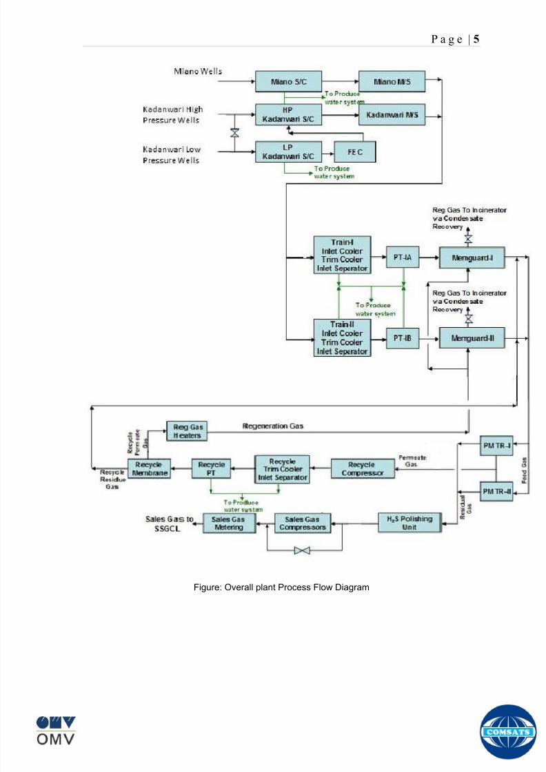
8102019 Gas sweetening Plant
httpslidepdfcomreaderfullgas-sweetening-plant 962
P a g e | 5
Figure Overall plant Process Flow Diagram
8102019 Gas sweetening Plant
httpslidepdfcomreaderfullgas-sweetening-plant 1062
P a g e | 6
Wellhead
A wellhead is the component at the surface of an oil or gas well that provides the
structural and pressure-containing interface for the drilling and production
equipment Its function is to maintain surface control of the well It forms a seal to
prevent well fluids from leaking or blowing at the surface They are rated for
working pressure of 2000 psi to 15000 psi (or greater)
When the well has been drilled and it is ready to provide an interface with the
reservoir rock and a tubular channel for the well fluids The surface pressure
control is provided by a Christmas tree which is installed on top of the wellhead
with valves and choke equipment to control the flow of well fluids during
production
Christmas tree
A Christmas tree is an assembly of valves spools and fittings used for an oil
well gas well water injection well gas injection well condensate well and other
types of wells
The primary function of a tree is to control the flow usually oil or gas out of the
well When the well and facilities are ready to produce and receive oil or gas tree
valves are opened and the formation fluids are allowed to go through a flow line
This leads to a processing facility A tree often provides numerous additional
functions including chemical injection points well intervention means pressure
relief means monitoring points (such as pressure temperature corrosion
erosion sand detection flow rate flow composition valve and choke position
feedback) and connection points for devices such as down hole pressure andtemperature transducers (DHPT) On producing wells chemicals or alcohols or
oil distillates may be injected to preclude production problems (such as
blockages)
The control system attached to the tree controls the down-hole safety valve
(SCSSV) while the tree acts as an attachment and means of the control system
to the down-hole safety valve
8102019 Gas sweetening Plant
httpslidepdfcomreaderfullgas-sweetening-plant 1162
P a g e | 7
Figure 1
Well Head and Christmas Tree
8102019 Gas sweetening Plant
httpslidepdfcomreaderfullgas-sweetening-plant 1262
P a g e | 8
Master Valves
The two lower valves are called the master valves Master valves are normally in
the fully open position and are never opened or closed when the well is flowing
(except in an emergency) to prevent erosion of the valve sealing surfaces They
are gate type valves
1 Lower Master Valve (LMV)
2 Upper Master Valve (UMV)
The lower master valve will normally be manually operated while the upper
master valve is often hydraulically actuated allowing it to be used as a means of
remotely shutting in the well in the event of emergency
Wing Valve
A wing valve is normally used to shut in the well when flowing thus preserving
the master valves for positive shut off for maintenance purposes The wing
valve can be a gate valve or ball valve Hydraulic operated wing valves are
usually built to be fail safe closed meaning they require active hydraulic pressure
to stay open This feature means that if control fluid fails the well will
automatically shut itself in without operator action
In Kadanwari well sites there is only one manually operated wing valve On the
other hand at Miano well sites there are two wing valves one being operated
manually and other hydraulically
Production Wing Valve
The right hand valve is often called the flow wing valve or the production wing
valve because it provides flow path for hydrocarbons to production facility
Kill wing valve
The left hand valve is often called the kill wing valve It is primarily used for
injection of fluids such as corrosion inhibitors or methanol to prevent hydrate
formation It is typically manually operated It can kill the well temporarily be
injection brine solution which provides a pressure head to well and temporarily
8102019 Gas sweetening Plant
httpslidepdfcomreaderfullgas-sweetening-plant 1362
P a g e | 9
suspends it for maintenance of well head Also it is used to permanently kill the
well A chemical is injected down the well that seals the piping down the well and
kills the well permanently
Swab valve
The swab valve is used to gain access to the well for wire line operations
intervention and other work over procedure On top of it is a tree adapter
and cap that will mate with various equipment For such operations a
lubricator is assembled up onto the top of the tree and the wire or coil is lowered
through the lubricator through swab valve and into the well This valve is typically
manually operated
Choke
A choke holds back pressure by restricting the flow opening at the well head This
is done to make better use of the gas for natural gas lift and to control the bottom-
hole pressure for recovery reasons
CHECK VALVE
The check is introduced in production flow line to prevent any reverse flow from
the line into the well It has a hinged flap which lifts to permit normal flow but
closes to prevent reverse flow
TOP ADAPTOR
The top adaptor is a fitting on top of the swab valve with a threaded connection
During normal well operations a pressure gauge is fitted to monitor flowing and
shut in wellhead pressures However during well service operations the cap can
be removed to allow installation of lubricators for wire-line operations
SCSSSV (Surface Control Sub Surface Safety Valve)
A subsurface safety valve is essentially a shutdown valve installed at the upper
wellbore for emergency shutdown to protect the production tubing and wellhead
in case of overpressure Subsurface safety valves can offer a barrier against flow
in the event of a wellhead collapse or other disastrous event Purpose of asubsurface safety valve (SSSV) is to avoid the ultimate disaster which can result
8102019 Gas sweetening Plant
httpslidepdfcomreaderfullgas-sweetening-plant 1462
P a g e | 10
in release of reservoir fluids to the surroundings This makes SSSV a very
important component of a well completion
A subsurface safety valve is typically a uni-directional flapper valve directed in
such a way that the flappers open downwards when pressure is applied from an
upward direction The flapper can only open in the downward direction So even if
high pressure is applied by the well fluids from a
downward direction a safety valve can remain
closed This makes a subsurface safety valve fail-
safe To open the valve hydraulic signal is sent from
the surface well control panel This hydraulic
pressure is responsible for keeping the flappers of
SSSV open and loss of hydraulic pressure result in
closing of the valve Thus wellbore can be isolated in
case of system failure or damage to the surface
facilities
Types of Christmas tree
There are two types of Christmas Tree
1 Solid block
2 Conventional
The solid block Christmas Tree has a central solid unit holding several valves
in a pre-constructed block Their advantage is the reduction in potential leak
paths and their higher pressure rating (Fig 2)
The conventional Christmas Tree is built up from individual valves bolted
together to form an assembly (Fig 3)
8102019 Gas sweetening Plant
httpslidepdfcomreaderfullgas-sweetening-plant 1562
P a g e | 11
Figure 2
Figure 3
8102019 Gas sweetening Plant
httpslidepdfcomreaderfullgas-sweetening-plant 1662
P a g e | 12
Wellhead Control Panel
Wellhead control panel is key equipment in oil amp gas industry to protect oilfield
facilities and environment from emergency incidents such as wellhead fire which
is one of main control systems to ensure oilfield oil production and transportation
to be safely operation according to international standards and national
regulation Wellhead control panel is composed of hydraulic power unit tubing amp
fitting and instrument valve and electrical control devices Hydraulic power unit
supply hydraulic resource to open and close safety valves including master
valves wing valves and SCSSSV
Its performs
Local OnOff SSV
Remote control SSV through RTU( remote terminal unit)
High-Low pressure sense shut-down automatically
Fusible Plug Anti-fire Shut-down automatically
Function of showing system pressure
Relief Valve shall be installed on each hydraulic circuit to prevent high
pressure
Function of showing hydraulic level and level switch for alarm
Function of defending pressure impact of system
Function of system pressure monitoring (by pressure transmitter of control
panel)
Function of remote emergency shut-down (by magnetic valve of control
panel)
Function of OnOff SSV monitoring (by pressure switch of control loop of
control panel)
8102019 Gas sweetening Plant
httpslidepdfcomreaderfullgas-sweetening-plant 1762
P a g e | 13
Chemical Injection
Chemical injection systems are commonly used in production facilities to prevent
or eliminate a wide range of problems that might negatively affect the production
flow It is done for flow assurance protection of process equipment such as
pipelines or to optimize processes in production facilities
Typical flow assurance chemicals are
Wax inhibitors
Pour point depressants
Asphaltene inhibitors
Corrosion inhibitors
A corrosion inhibitor is a chemical compound that is added to liquid or gas to
decreases the corrosion rate of a material typically a metal or an alloy The
effectiveness of a corrosion inhibitor depends on fluid composition quantity of
water and flow regime Its common mechanism involves formation of a coating
8102019 Gas sweetening Plant
httpslidepdfcomreaderfullgas-sweetening-plant 1862
P a g e | 14
which prevents access of the corrosive substance to the metal The corrosive
agents are generally oxygen hydrogen sulfide and carbon dioxide
At our production site the major risk is corrosion of piping and equipment The
maximum allowable corrosion rate is approximately 02 mm per year and
corrosion rate without inhibitor could be approximately 11 mm per year so the
corrosion protection program is designed to achieve a target corrosion rate of
less than 01 mm per year which is achieved by an inhibitor system efficiency of
99 Inhibitor is injected into the well stream flow through an atomizing nozzle
located downstream of the respective wellhead coolers at the duplexcarbon steel
interface In normal operation as per NALCO standards chemical (brand name
EC1144B) at rate of frac12 Liter per MMSCFD of gas is being injected into the flow
line of miano15 flow lines made of carbon steel Moreover the composition can
vary depending upon the composition of well fluids and material of pipeline This
method of injection ensures even distribution of the chemical on the interior
surface of the pipeline The individual well sites are equipped with Chemical
Injection Packages comprising of a stainless steel storage tank and two
pneumatic motor driven pumps in parallel Instrument gas is used to drive the
pumps Normally one pump is running with the other standby
Water Conning
Water coning is a term used to describe the mechanism underlying the upward
movement of water into the perforations of a producing well Coning can seriously
impact the well productivity and influence the degree of depletion and the overall
recovery efficiency of the reservoir The specific problems of water coning are
listed below
Costly added water handling
Gas production from the original or secondary gas cap reduces pressure
Reduced efficiency of the depletion mechanism
The water is often corrosive and its disposal costly
The affected well may be abandoned early
Loss of the total field overall recovery
8102019 Gas sweetening Plant
httpslidepdfcomreaderfullgas-sweetening-plant 1962
P a g e | 15
Therefore conning has an important influence on operations recovery and
economics The phenomena is shown in picture below
Corrosion
Corrosion is referred as chemical deterioration of a metal Commonly this
means loss of electrons of metals reacting with water and oxygen
Weakening of iron due to oxidation of the iron atoms is a well-known
example of electrochemical corrosion This is commonly known as
rust Most structural alloys corrode merely from exposure to moisture
in the air but the process can be strongly affected by exposure to
certain substances Corrosion can be concentrated locally to form a pit
or crack or it can extend across a wide area to produce general
deterioration (uniform corrosion)
The following reaction takes place at the active sites
2Fe =gt 2Fe++ + 4e-
The free electrons travel through the metal path to the less active sites where
the following reaction takes place
O2 + 4e- + 2H20 =gt 4 OH-
8102019 Gas sweetening Plant
httpslidepdfcomreaderfullgas-sweetening-plant 2062
P a g e | 16
Recombination of these ions at the active surface produce the following
reaction which yields the iron-corrosion product ferrous hydroxide
2Fe + O2 + 2H2O =gt 2Fe (OH) 2
CORROSION PROTECTION SYSTEM
Coatings and painting
Painting and the application of enamel bitumen and PVC
coating are the most common anti-corrosion treatments They
work by providing a barrier of corrosion-resistant material
between the damaging environment and the structural material
Corrosion Inhibitors
Corrosion inhibitor is injected into the flow lines as mentioned in
detail on page 8
Cathodic Protection
Cathodic Protection (CP) is a technique used to control the corrosion of a
metal surface by making it the cathode of an electrochemical cell It
converts all of the anodic (active) sites on the metal surface to cathodic
(passive) sites by supplying electrical current (or free electrons) from an
alternate source It is accomplished in two ways
a) A simple method of protection connects protected metal to a more easily
corroded sacrificial metal to act as the anode The sacrificial metal then
corrodes instead of the protected metal The process is similar to a simple
DC cell in which the more active metal becomes the anode and corrodes
whereas the less active metal becomes the cathode and is protected
b) For larger structures galvanic anodes cannot economically deliver enough
current to provide protection Therefore impressed current cathodic
protection (ICCP) systems are used These consist of anodes connected
to a DC power source In remote areas power sources such as solar
panels may be used The output DC negative terminal is connected to the
8102019 Gas sweetening Plant
httpslidepdfcomreaderfullgas-sweetening-plant 2162
8102019 Gas sweetening Plant
httpslidepdfcomreaderfullgas-sweetening-plant 2262
P a g e | 18
frequently to limit liquid holdup and minimize the slug volumes of liquid which can
be generated by the system
Coating
Pigs may be used to apply internal pipe coatings such as epoxy coating
materials in operating pipelines Pigs may also be used with corrosion inhibitors
to distribute and coat the entire internal wetted perimeter
Inspection
Pigs are being used more frequently as inspection tools Gauging or sizing pigs
are typically run following the completion of new construction or line repair to
determine if there are any internal obstacles bends or buckles in the pipe Pigs
can also be equipped with cameras to allow viewing of the pipe internals
Electronic intelligent or smart ldquopigsrdquo that use magnetic and ultrasonic systems
have been developed and refined that locate and measure internal and external
corrosion pitting dents buckles and any other anomalies in the pipe wall
Intelligent pigs
The accuracy of location and measurement of anomalies by the intelligent pigs
has continued to improve Initially the electronics and power systems were so
large that intelligent pigs could be used only in lines 30 in and greater in size
The continued sophistication and miniaturization of the electronic systems used
in the intelligent pigs has allowed the development of smaller pigs that can be
used in small-diameter pipelines Newly enacted DOT pipeline-integrity
regulations and rules acknowledge the effectiveness of the intelligent pigs and
incorporate their use in the pipeline-integrity testing process
Compressors
A gas compressor is a mechanical device that increases the pressure of a gas by
reducing its volume Gas pressure is increased by forcing gas molecules together
to reduce gas volume When volume is reduced gas pressure increases
All gases have large spaces among their molecules These spaces could be
enhanced further and decreased by doing some work Work done which is used
8102019 Gas sweetening Plant
httpslidepdfcomreaderfullgas-sweetening-plant 2362
P a g e | 19
for the enhancement of these spaces is called expansion and work done to
minimize these spaces is called compression All gases while expansion
produces cooling effect and while compression of gases raises there
temperature Compression is a term used to force gases to occupy smaller
volumes by increasing their pressure Volume of gases is interlinked with
temperature and pressure of the gas which is cleared by 2 laws govern gas
compressions
Boyles Law
Charles Law
The main types of compressor are listed below
Front End Compressor
The plant currently processes gas from a number of wells The flow and pressure
from some of these wells (currently K-10 K-11 amp K-12) has declined and they
cannot be fed directly into the Central Processing Facility To recover the
maximum gas reserves from these wells a Front End Compressor is employed
The compressor is a two stage double acting gas engine driven reciprocating
(PT) compressor Double acting means that gas is compressed on each end of
the piston It normal operates with a speed range of 600 to 900 RPM and isequipped with four compressor cylinders two for each stage Each cylinder is
8102019 Gas sweetening Plant
httpslidepdfcomreaderfullgas-sweetening-plant 2462
P a g e | 20
also equipped with a variable volume head end pocket
In case of compressor emergency shutdown the production chokes and the
Upper Master Valves on the on line wells will close and operator will be notified in
central control room Sweet gas from gas distribution network is used to operate the
gas engine driver of the compressor package The detailed scheme of working is
shown in figure (page 22 )
PT Reciprocating Compressor
The mechanical cycle of piston tube reciprocating compressor comprises four
strokes the expansion stroke the intake stroke the compression stroke and the
discharge stroke
Expansion Stroke
As the piston moves back on the expansion stroke the chamber volume
increases and the pressure drop As the pressure drops the discharge valve
closes since there is greater pressure in the discharge line than in the chamber
Intake Stroke
As the piston moves back during the intake stroke the pressure decreases until it
is less than the pressure in the inlet line This higher intake pressure opens the
inlet valve and gas rushes into the cylinder equalizing the pressure there with
the intake pressure The compression chamber is now at or near the intake
pressure
Compression Stroke
The piston now starts the compression stroke by moving forward decreasing the
chamber volume and increasing the pressure The increased pressure is now
higher than the intake pressure causing the intake valve to close
Discharge Stroke
The piston continues to move to the left during the discharge stroke This creates
an increase in chamber pressure until it is greater than the discharge pressure
When this happens the Discharge valve opens and the compressed air from the
8102019 Gas sweetening Plant
httpslidepdfcomreaderfullgas-sweetening-plant 2562
P a g e | 21
cylinder goes into the discharge line The compression cycle is then repeated
from the stage
Compressor Capacity
The capacity of the compressor depends upon cylinder displacement That
displacement is simply the volume that the piston displaces (moves) as it travels
from one end of the cylinder to the other Capacity and displacement is equal to
the cross-sectional area of the cylinder times the length of the stroke
Lubrication and Cooling
Lubricating oil is circulated through the system by a gear pump which is chain
driven from the engine crank shaft The oil pump is mounted on the engine front
housing
The pump operates between 30 - 40 psig
8102019 Gas sweetening Plant
httpslidepdfcomreaderfullgas-sweetening-plant 2662
P a g e | 22
A circulating pump deliver cooling water to the water jackets in the cylinder block
flowing around the cylinder liners and is directed into the cylinder heads Each
cylinder head has water cooled exhaust elbows which outlet the water into the
water cooled exhausts From the end of engine the water flows to compressor
1st and 2nd stage cylinders and compressor lube oil cooler (LOwater heat
exchanger) The water from the compressor cylinder and lube oil cooler returns
to engine water cooled exhaust
Figure Flow diagram of Front End Compressor
8102019 Gas sweetening Plant
httpslidepdfcomreaderfullgas-sweetening-plant 2762
P a g e | 23
Centrifugal Compressor
Centrifugal compressors are machines in which velocity and pressure given to air
or gas in a radial direction by one or more impellers diffuser combination In a
centrifugal compressor the mechanical energy is increased by centrifugal action
The gas enters the suction eye of a high speed rotary element called the impeller
which carries radial vanes integrally cast in it As the impeller rotates the blades
of the impeller force the gas outward from the center the impeller to the outer rim
of impeller the increase in velocity of the gas creates a flow pressure area at the
eye of the impeller The gas at the outer rim of the impeller is forced in to a
passage way called a diffuser where the velocity decreases in the pressure of the
gas
Inlet
The inlet to a centrifugal compressor is typically a simple pipe It may include
features such as a valve and both pressure and temperature instrumentation
Centrifugal impeller
The key component that makes a compressor centrifugal is the centrifugal
impeller shown above It is the impellers rotating set of vanes (or blades) that
gradually raises the energy of the working gas This is identical to an axial
compressor with the exception that the gases can reach higher velocities and
energy levels through the impellers increasing radius
8102019 Gas sweetening Plant
httpslidepdfcomreaderfullgas-sweetening-plant 2862
P a g e | 24
Diffuser
The next key component to the simple centrifugal compressor is the diffuser
Downstream of the impeller in the flow path it is the diffusers responsibility to
convert the kinetic energy (high velocity) of the gas into pressure by gradually
slowing (diffusing) the gas velocity
SEPERATORS
A well-stream is a mixture of gases hydrocarbon liquids water solids and
contaminants Due to variations in pressure and temperature gases evolve from
the liquids water vapor condenses and some of the well-stream changes to liquid
and free gas The separation of well-stream fluids takes place in a separator This
pressure vessel is manufactured in three forms
1 horizontal
2 vertical
3 spherical
To help separation the vessel is normally designed with a series of internal
fittings These fittings are built into the separator to ensure total phase separation
of the well-stream
In gas plants separators are given alternative names due to the function they
perform in the process system A scrubber does a similar job to a knockout drum
However the scrubber usually separates a stream containing high gas-to-liquid
ratios The knockout drum is used where a high degree of liquids are entrained in
the gas
Fluid flow from a well can include gas condensable liquid vapors water water
vapor crude oil and solids As well-stream fluids reach ground level where
pressure is lower than in the reservoir the capacity of the liquid to hold gas in
solution decreases and gas separates out of the oil
Separation depends upon the effect of gravity to separate liquids For adequate
separation one fluid must be lighter than the other fluid For example distillates
8102019 Gas sweetening Plant
httpslidepdfcomreaderfullgas-sweetening-plant 2962
P a g e | 25
(gasoline kerosene etc) and crude oil will not separate in a vessel because they
tend to dissolve in each other Because a separator basically depends upon
gravity to separate the fluids the ease with which separation takes place
depends upon the difference in density of the fluids
Droplets of liquid will separate from gas provided
a) The gas remains in the separator long enough
b) The gas flow remains constant to provoke separation
The difference in density between a gas and liquid will therefore determine the
maximum flow rate of liquid in the vessel
Figure Two phase horizontal separator
Gas bubbles in the liquid will break out in some oil field applications in 30 to 60
seconds Consequently the separator is designed so that the liquid remains in
the vessel for 30 to 60 seconds The length of time that a liquid remains in the
vessel is called its residence time Residence time differs widely from field to field
depending upon viscosity and API Gravity
Another important factor which must be considered is temperature Generally a
decrease in operating temperature will increase the liquid recovery in a separator
8102019 Gas sweetening Plant
httpslidepdfcomreaderfullgas-sweetening-plant 3062
P a g e | 26
as the gas condenses By reducing the pressure on the fluid flash separation
occurs resulting in a flow through the separator which is controlled by external
instrumentation
COALESCENCE
Another important principle in fluid separation is that of coalescence This means
the coming together of liquid droplets created by the force of gravity
A common example of coalescing occurs when drops of water form on the
windshield of a car as it is driven in fog As the tiny drops or water which make up
the fog strike the windshield they combine and eventually form a drop large
enough to run down the glass
Several of the internal devices of a separator such as deflector plates
straightening vanes and even the vessel walls are forms of coalescers In each
vessel drops of liquid adhere to the surface of the device and combine with other
8102019 Gas sweetening Plant
httpslidepdfcomreaderfullgas-sweetening-plant 3162
P a g e | 27
drops until the drop is large enough to fall out The effectiveness of separation
will also depend upon the total amount of coalescing surface area that is present
There are many different types of separators used in the Oil amp Gas industry
Consequently separators are manufactured with one two or several internal
fittings depending on their use and quick removal of these fluids from the vessel
DEFLECTOR PLATES
These are fitted in front of the inlet to the separator and can be net or
dish-shaped Their purpose is to absorb the impact of the incoming fluids and to
encourage the separation of gas and liquids They also slow the flow rate of the
liquids through the vessel
WEIRS
A weir is a metal wall which is fitted across the inside of the vessel normally to a
height of 50 of the overall height of the separator Its purpose is to assist the
process of three phase separation The inlet fluids (oil plus water) are given time
to separate in the liquid accumulation section The water level (interface) is
normally controlled at 50 of the height of the weir Oil floating on the wateroverflows the weir and accumulates in the small oil compartment where it is
drawn off under level control
CENTRIFUGAL DEVICES
These are used in both vertical and horizontal separators for gas-liquid
separation The device imparts a swirling motion to the fluids entering the vessel
Centrifugal force causes the heavier liquids to travel outwards towards the walls
of the vessel and the lighter gases to flow up the centre Centrifugal devices are
also known as cyclones
VORTEX BREAKERS
When liquid flows through a drain outlet a vortex (whirlpool) will form This can
be seen when we pull the plug from a sink or bath tub The same would happen
as water and oil flow from the separator This condition a vortex could allow gas
to flow down the centre of the whirlpool and enter the liquid phase causing
8102019 Gas sweetening Plant
httpslidepdfcomreaderfullgas-sweetening-plant 3262
P a g e | 28
pressurizing of tanks etc To stop this happening vortex breakers are fitted to all
liquid outlets Although they come in a number of different designs vortex
breakers all serve the same purpose - to prevent a whirlpool from forming
MIST OR DEMISTER PADS
The gas which is released from the fluids in the separator still contains droplets of
oil and water which coalesce and fall when the drops get large enough The
demister pad assists in this process Made from knitted wire and contained within
a sturdy frame it causes the gas to continually change its direction of flow
Because gas changes direction far easier than liquid the gas will flow around
each strand of wire whilst the liquid entrained in the gas stream will continue and
stick to the wire
COALESCING PLATES
There are several different forms of coalescing devices the most common of
which are coalescing plates These plates are mounted in the flow stream of the
fluids and assist in breaking down oil-water emulsions The fluid is forced to
follow a path that constantly changes direction This causes the water droplets to
gather together or coalesce and fall to the bottom of the separator The same
principle is used to separate gas and oil mixtures when the oil droplets are
induced to coalesce Simply stated every surface within the separator including
the separator walls assists with the coalescing process
STRAIGHTENlNG VANES
These are often fitted to horizontal separators to remove turbulence in the gas
stream after initial separation at the inlet deflector
FLOAT SHEILD
Internal floats are used as level controllers Any agitation of the liquid surface or
the effect of coalesced liquids falling on the float may cause control problems
Therefore a float shield is fitted to enclose the float creating an area of still liquid
8102019 Gas sweetening Plant
httpslidepdfcomreaderfullgas-sweetening-plant 3362
P a g e | 29
MEMBRANES
The gas contains 12 carbon dioxide and 22 ppm of hydrogen sulphide at 115oF
and 1100 psig This needs to be removed before the gas can be exported The
majority of carbon dioxide hydrogen sulphide and water is removed by means of
membranes
Membranes are thin semipermeable barriers that selectively separate some
compounds from others Currently the only commercially workable membranes
used for CO2 removal are polymer based for example cellulose acetate
polyimides polyamides polysulfone polycarbonates and polyetherimide The
membrane does not operate as a filter where small molecules are separated
from larger ones through a medium with pores rather it separates based on how
well different compounds dissolve into the membrane and diffuse through it The
membranes are manufactured in flat sheets consisting of an extremely thin
nonporous layer mounted on a much-thicker and highly porous layer of the same
material providing mechanical strength The flat sheets are combined into a
spiral-wound element (Figure below) Feed gas enters along the side of the
membrane and passes through the feed spacers As the gas travels between
membrane sheets CO2 H2S and H2O permeate through the membrane and are
collected in the permeate tube The driving force for transport is the high-feed
pressure and low-permeate pressures The gas on the feed side that does not
permeate leaves through the side of the element opposite the feed position Once
the membranes have been manufactured into elements six to 12 elements are
joined together and inserted into a tube Multiple tubes are mounted on skids in a
horizontal orientation
8102019 Gas sweetening Plant
httpslidepdfcomreaderfullgas-sweetening-plant 3462
P a g e | 30
Figure Membrane general Working
In high H2S applications most polymers have been shown to have very little
resistance to H2S plasticization (ldquosofteningrdquo of the membrane) and as a
consequence can only be used at very low H2S partial pressure limits Cellulose
acetate membranes in contrast have been shown to be applicable at extreme
H2S partial pressure conditions It is these membranes that have been utilized in
the testing to determine the limits of membrane performance in high H 2S
applications
The primary membranes used in Kadanwari facility are Cellulose acetate
Cellulose acetic acid and acetic anhydride are mixed together and reacted to
form cellulose acetate polymers This process is aided by the addition of a small
amount of sulfuric acid which is subsequently neutralized during processing
However the membranes are bought from UOP (vendor) and installed for use
8102019 Gas sweetening Plant
httpslidepdfcomreaderfullgas-sweetening-plant 3562
P a g e | 31
How membrane work
The basic principle of separation is selectivity of certain components of a mixture
for the membrane For example the cellulose acetate membrane has very high
selectivity for CO2 and H2S as compared to CH4 Therefore such type of
membrane can be used in gas sweetening process
The selectivity is directly related to the Permeability of gas which accounts that
which gas can pass across the membrane more easily In simple words
membranes being polymer materials are made of long chains of molecules The
different structure of polymer materials only allow selective molecules to pass
through them depending upon chemical and physical compatibility Thus
permeability depends upon choice of polymer
The permeability is determined by permeability coefficient (P) and is product of
solubility (S) and diffusivity (D)
P = S D
Solubility
The solubility is mainly determined by ease of condensation Heavy molecules
are more readily condensed Therefore higher molecular weighted molecules will
more easily condensed and therefore have greater solubility
Molecule Molecular weight
CH4 16
H2S 34
CO2 44
8102019 Gas sweetening Plant
httpslidepdfcomreaderfullgas-sweetening-plant 3662
P a g e | 32
Diffusivity
Diffusivity is ease of molecule to penetrate into some material It depends on size
of gas molecule Here size of molecule is not to be confused by molecular weight
it is the size of the structure Eg the size of O2 molecule is smaller than N2
Molecule Molecular Diameter (Ao)
CO2 33
H2S 36
Ch4 40
For cellulose acetate
DCO2DCH4 S CO2S CH4 P CO2P CH4
45 73 308
Chemical degradation
Cellulose acetate polymer is chemically degraded by a process called hydrolysis
which means breaking apart by the addition of water This is a chemical reaction
in which water is added to the cellulose acetate polymer causing the release of
acetic acid molecules This process proceeds stepwise until all the acetate
groups are released resulting in the reformation of cellulose Moreover alcohols
aromatic hydrocarbons or solvents with chlorine nitro benzene or similar
aromatic solvents will harm the membrane It will expand and lose plastification in
contact with them
Effect of Temperature
The permeation rates of all gases increases with increasing temperature
however membrane selectivity for CO2 over hydrocarbon decreases at higher
8102019 Gas sweetening Plant
httpslidepdfcomreaderfullgas-sweetening-plant 3762
P a g e | 33
temperature Consequently CO2 removal will improve as operating temperature
increases but hydro carbon recovery will decrease
Primary Membrane
The primary membranes comprise of two trains Each train consists of two
sections AB and CD each section consists of a 30 tube membrane skid (A and
C) followed by a 25 tube skid (B and D) The conditioned gas (after pre-
treatment) enters the primary membrane via the particulate filter adjacent to the
skid The gas is fed to the membranes through a common inlet manifold which
supplies primary membranes skids A and C A pressure control loop located
upstream of the manual inlet isolation valve is provided to maintain a constant
supply pressure to the membrane skid and to allow for preheating at the inlet
prior to skid start-up This pressure control loop can also be used during start-up
to control the pressurization of the pretreatment skid and associated pipes to the
primary membranes
The gas passes through membrane skid A the residual gas exiting the membrane
skid is sent to skid B and the permeate to common permeate discharge header An
identical arrangement is provide on the inlet to skid C as provided on skid A Theresidual gas from skid B combines with the residual gas from skid D in a common
discharge header and is then sent to the H2S polishing towers via the feed coolers
on the pre-treatment skid The permeate from skid B is sent to the common
permeate discharge header The permeate discharge header sends the gas to
either the recycle compressor or the vent header via a pressure control loop
Overpressure protection for the membranes is provided by a pressure safety valve
on the supply header to the membrane banks
8102019 Gas sweetening Plant
httpslidepdfcomreaderfullgas-sweetening-plant 3862
P a g e | 34
Secondary (Recycle) Membrane
The recycle membranes comprise of a single train with two skids each with four
banks of membrane tubes The conditioned gas from the discharge of the recycle
pre-treatment skid is routed to the first recycle membrane skid The gas passes
through the membranes the residual gas is fed to primary membrane (skid A) inlet
via feed gas cooler and permeate to the common permeate discharge header An
identical arrangement is provide on the inlet to skid B Permeate from the recycle
membrane skids A and B is routed to the vent header Some portion of permeate is
heated and sent for regeneration in Mem-Guard units Nitrogen purge can be
connected downstream of the inlet isolation valve on each skid to enable the
membrane tubes to be purged and left pressurized during prolonged shutdown
8102019 Gas sweetening Plant
httpslidepdfcomreaderfullgas-sweetening-plant 3962
P a g e | 35
Figure Flow Diagram of Recycle membrane unit
8102019 Gas sweetening Plant
httpslidepdfcomreaderfullgas-sweetening-plant 4062
P a g e | 36
ADVANTAGES OF MEMBRANE SYSTEMS
Membrane systems have major advantages over more-traditional methods of
acid gas removal
Lower capital cost Membrane systems are skid mounted and so the
scope cost and time taken for site preparation are minimal Installation
costs are significantly lower than alternative technologies especially for
remote areas Furthermore no additional facilities for solvent storage and
water treatment needed by other processes are required
Lower operating costs The only major operating cost for single-stage
membrane systems is membrane replacement This cost is significantly
lower than the solvent replacement and energy costs associated with
traditional technologies The improvements in membrane and
pretreatment design allow a longer useful membrane life which further
reduces operating costs The energy costs of multistage systems with
large recycle compressors are usually comparable to those for traditionaltechnologies
Deferred capital investment Often contracted sales-gas flow rates
increase over time as more wells are brought on-line With traditional
technologies the system design needs to take this later production into
account immediately and so the majority of the equipment is installed
before it is even needed The modular nature of membrane systems
means that only the membranes that are needed at start-up need be
installed The rest can be added either into existing tubes or in new skids
only when they are required
Operational simplicity and high reliability Because single-stage
membrane systems have no moving parts they have almost no
8102019 Gas sweetening Plant
httpslidepdfcomreaderfullgas-sweetening-plant 4162
P a g e | 37
unscheduled downtime and are extremely simple to operate They can
operate unattended for long periods of time The addition of a recycle
compressor adds some complexity to the system but still much less than
with a solvent- or adsorbent-based technology Multistage systems can be
operated at full capacity as single-stage systems when the recycle
compressor is down
Good weight and space efficiency Skid construction can be optimized
to the space available This space efficiency is especially important for
offshore environments where deck area is at a premium and is the
reason why so many new offshore developments have chosen to use
membranes for acid gas removal Figure 6 illustrates the space efficiency
of membrane systems The membrane unit in the lower left corner
replaced all the amine and glycol plant equipment shown in the rest of the
picture
Adaptability Because membrane area is dictated by the percentage of
acid gas removal rather than absolute acid gas removal small variations
in feed acid gas content hardly change the sales-gas acid gas
specification For example a system designed for 10 down to 3 acid
gas removal produces a 35 product from a 12 feed gas and a 5
product from a 15 feed gas
Design efficiency The membrane and pretreatment systems integrate a
number of operations such as dehydration CO2 and H2S removal dew-
point control and mercury removal Traditional acid gas removal
technologies require all of these operations as separate processes and
may also require additional dehydration because some technologies
saturate the product stream with water
8102019 Gas sweetening Plant
httpslidepdfcomreaderfullgas-sweetening-plant 4262
P a g e | 38
Power generation The permeate gas from membrane systems can be
used to provide fuel gas for power generation either for a recycle
compressor or other equipment
Ideal for debottlenecking Because expanding solvent- or adsorbent-
based acid gas removal plants without adding additional trains is difficult
an ideal solution is to use membranes for bulk acid gas removal and leave
the existing plant for final cleanup An additional advantage is that the
permeate gas from the membrane system can often be used as fuel for
the existing plant thus avoiding significant increase in hydrocarbon
losses
Environmentally friendly Membrane systems do not involve the
periodic removal and handling of spent solvents or adsorbents Permeate
gases can be flared used as fuel or re-injected into the well Items thatdo need disposal such as spent membrane elements can be incinerated
Ideal for remote locations Many of the factors mentioned above make
membrane systems a highly desirable technology for remote locations
where spare parts are rare and labor unskilled Furthermore solvents
storage and trucking water supply power generation or extensive
infrastructure are not required
Re-injection optimizations Since the permeate stream from the
membrane system can be operated at elevated pressures it is possible to
further pressurize by re-injection compression train
8102019 Gas sweetening Plant
httpslidepdfcomreaderfullgas-sweetening-plant 4362
P a g e | 39
Sorption
Sorption is a physical and chemical process by which one substance becomes
attached to another
It is of two main types
1 Absorption
2 Adsorption
Absorption
Absorption is a physical or chemical phenomenon or process in which atoms
molecules or ions enter some bulk phase ndash gas liquid or solid material This is a
different process from adsorption since molecules undergoing absorption are
taken up by the volume not by the surface (as in the case for adsorption)
Absorption process may be chemical (reactive) or physical (non-reactive)
Physical absorption
Physical absorption or non-reactive absorption is made between two phases ofmatter a liquid absorbs a gas or a solid absorbs a liquid
When a liquid solvent absorbs a gas mixture or part of it a mass of gas moves
into the liquid For example water may absorb oxygen from the air This mass
transfer takes place at the interface between the liquid and the gas at a rate
depending on both the gas and the liquid This type of absorption depends on the
solubility of gases the pressure and the temperature The rate and amount of
absorption also depend on the surface area of the interface and its duration in
time
When a solid absorbs a liquid mixture or part of it a mass of liquid moves into the
solid For example a clay pot used to store water may absorb some of the water
This mass transfer takes place at the interface between the solid and the liquid
at a rate depending on both the solid and the liquid
8102019 Gas sweetening Plant
httpslidepdfcomreaderfullgas-sweetening-plant 4462
P a g e | 40
Chemical absorption
Chemical absorption or reactive absorption is a chemical reaction between the
absorbed and the absorbing substances Sometimes it combines with physical
absorption This type of absorption depends upon the stoichiometry of the
reaction and the concentration of its reactants
Adsorption
Adsorption is the adhesion of atoms ions or molecules from a gas liquid or
dissolved solid to a surface This process creates a film of the adsorbate on the
surface of the adsorbent The binding to the surface is usually weak and
reversible Compounds with color and those that have taste or odor tend to bind
strongly Compounds that vibrate at frequencies in the visible spectrum are very
often are strongly adsorbed on activated carbon
The most common industrial adsorbents are activated carbon silica gel and
alumina because they present enormous surface areas per unit weight
Depending on the nature of attractive forces existing between the adsorbate and
adsorbent adsorption can be classified as
i) Physical adsorption
ii) Chemical adsorption
i) Physical adsorption (Physisorption)
In physical adsorption the forces of attraction between the molecules of the
adsorbate and the adsorbent are of the weak van der Waals type Since the
forces of attraction are weak the process of physisorption can be easily reversed
by heating or decreasing the pressure of the adsorbate (as in the case of gases)
8102019 Gas sweetening Plant
httpslidepdfcomreaderfullgas-sweetening-plant 4562
P a g e | 41
ii) Chemical adsorption (Chemisorption)
In chemisorption the forces of attraction between the adsorbate and the
adsorbent are very strong the molecules of adsorbate form chemical bonds with
the molecules of the adsorbent present in the surface
Adsorption is generally accompanied by release of energy that is most
adsorption processes are exothermic in nature Adsorption is a spontaneous
process therefore its free energy change is negative (∆Glt0) However the
entropy change associated with adsorption is generally negative because the
adsorbate molecules lose their translation freedom when they get attached to the
surface of the adsorbent Therefore in order for ∆G to be negative the enthalpy
change (∆H) must be sufficiently negative such that (∆G=∆H-T∆S) lt 0 This
explanation accounts for exothermic adsorption processes In cases where
endothermic adsorption occurs the entropy change ∆S is sufficiently positive
such that ∆G remains negative
Pre treatment
The main function of pretreatment skid is to provide membrane inlet specification
gas as mentioned by the vendor UOP It removes the contaminants that would
poison the membranes like dust solids (adsorbent particles) lube oil heavy
hydrocarbons etc It consists of
Feed Cooler
Feed Gas Scrubber
Filter Coalescer
Feed Gas Heater
Activated Carbon Guard Filter
Particle Filter
8102019 Gas sweetening Plant
httpslidepdfcomreaderfullgas-sweetening-plant 4662
8102019 Gas sweetening Plant
httpslidepdfcomreaderfullgas-sweetening-plant 4762
P a g e | 43
The regeneration is carried out by heated permeate gas from the recycle
membranes at 450oF The vessel is depressurized to 20 psi and heated gas is
introduced from top The gas carries out the adsorbed contaminants and leaves
the vessel from bottom cleaning the adsorbent This contaminated gas is burnt in
the flare
UOP the vendor of Memguard unit has never disclosed that what substance
MG3 and MG5 exactly are But as mentioned by vendor that both care class of
aluminosilicates Therefore MG3 can be potassium aluminosilicate and MG5 can
be Calcium aluminosilicate These are molecular sieves adsorbents Molecular
sieves are a microporous material which can selectively adsorb gases andliquids They are synthetic zeolites (crystalline metal aluminosilicates) which
upon dehydration can efficiently and selectively remove water or other
solvents The selectivity of a molecular sieve is determined by its pore size
molecules with a critical diameter which is less than the pore size will be
efficiently adsorbed while larger molecules will be excluded
8102019 Gas sweetening Plant
httpslidepdfcomreaderfullgas-sweetening-plant 4862
P a g e | 44
3A Molecular Sieve Adsorbent
The 3A molecular sieve adsorbent has a 3 angstrom (3A) pore size which means
that any molecule that is larger than the 3 angstrom pores will not be adsorbed
The 3A molecular sieve is the potassium type of A crystalline structure and is a
form of alkali Aluminosilicate For a 3A molecular sieve the sequence rate that
adsorption occurs is He Ne N and H2O
Due to the crystalline structure molecular sieves that have a 3 angstrom pore
size have a very high rate of adsorption and properties that promote a longer life
for products treated by the sieve The most common use for the 3A molecular
sieve is to remove water and moisture from materials that are in gas and liquid
form
5A Molecular Sieve Adsorbent
These are molecular sieve adsorbents with a pore size of 5 angstrom (5A) 5A
molecular sieves are unable to adsorb any molecules or impurities that are
smaller than 5A It is calcium form of type A crystalline structure and is form of analkali-aluminosilicate that is most commonly used to separate isomerous alkanes
from normal alkanes and to co-adsorb moisture and water along with carbon
dioxide from gases In additional 5A molecular sieves are used for gaseous
pressure swing adsorption (PSA)mdashthat is to separate particular gases from other
gases
Adsorption of nC4H10
Adsorption of nC4H10
Adsorption of C3H8 to C22H46
Adsorption of Freon-12 (dichlorodifluoromethane)
Natural gas drying
Normal- and iso-paraffin separation
Separation of aromatic
8102019 Gas sweetening Plant
httpslidepdfcomreaderfullgas-sweetening-plant 4962
P a g e | 45
Inlet Composition of Memguard vessel
COMPSOSITION MOLE
CARBON DIOXIDE 1096
MEHTANE 8593
ETHANE 173
PROPANE 023
I-BUTANE 008
N BUTANE 004
PENTANES 004
HEXANE + 000
NITROGEN 076
WATER 007
Outlet Composition of Memguard vessel
COMPSOSITION MOLE
CARBON DIOXIDE 1098
MEHTANE 8608
ETHANE 173
PROPANE 023
I-BUTANE 008N BUTANE 004
PENTANES 004
HEXANE + 000
NITROGENT 076
WATER 000
H2S polisher
The H2S polishing unit has been designed to treat 187 MMscfday of natural gas
containing up to 11 CO2 and 21 ppm H2S where the level of the CO2 and H2S
is reduced using a MemGuard Membrane separation unit The unit is situated
down-stream of the membrane unit and will further reduce the level of H2S in the
processed gas to a sales gas specification of 38 ppm
8102019 Gas sweetening Plant
httpslidepdfcomreaderfullgas-sweetening-plant 5062
P a g e | 46
This process uses three non-regenerable fixed bed absorber vessels using a low
temperature high activity absorbent The absorbent is a mixture of activated
metal oxides (mainly zinc oxide) The three towers can are generally operated in
parallel arrangement but on demand can be used in series (any of alternate
arrangements of A B C vessels) as shown in figure
The higher sales gas flow rate increased the catalyst consumption and
replacement frequency
ZnO + H2S =gt ZnS + H20
Routine samples are taken from the beds to provide a check on each bed
performance and to follow the saturation profile during the absorbent life After
the adsorbent has been fully utilized the adsorption vessels are recharged with
new adsorbent discarding the utilized one in a safe manner
109oF
1215 psig
Before H2S Polishing After H2S Polishing
8102019 Gas sweetening Plant
httpslidepdfcomreaderfullgas-sweetening-plant 5162
P a g e | 47
Figure
H2S Tower
Inlet pipe
4 Drums of 19mm
ceramic Balls
6 Micron mesh
5 Drums of 50mmceramic
1 Drums of19mm ceramic
01 Drums of6mm ceramic
112 drums of
Catalist ZnO
8102019 Gas sweetening Plant
httpslidepdfcomreaderfullgas-sweetening-plant 5262
P a g e | 48
Recycle Compressor
The permeate gas of the primary membrane unit carries recoverable amount of
CH4 It is fed to recycle membrane unit for further CH 4 recovery But the
permeate pressure from primary membranes which has been reduced to 12 psi
must be regenerated to 1200 psi for the gas to be fed again to the system For
this purpose we have employed recycle compressor The compressor is a four
stage centrifugal compressor It is driven by gas turbine of 31200 HP It has 25
MW producing capacity
Figure Recycle Compressor Process Flow Diagram
8102019 Gas sweetening Plant
httpslidepdfcomreaderfullgas-sweetening-plant 5362
P a g e | 49
Sales Gas Compressor
Gas from H2S polishing unit is sent to sales gas compressor where its pressure
is enhanced to 1100 psi so it may be injected to SNGPL high pressure trunk line
Sales gas compressor is single stage gas turbine driven
Figure Process Flow of Sales Gas Compressor
8102019 Gas sweetening Plant
httpslidepdfcomreaderfullgas-sweetening-plant 5462
P a g e | 50
Cooling Towers
A cooling tower is a heat rejection device which extracts waste heat to theatmosphere through the cooling of a water stream to a lower temperature Hot
water from the system enters the cooling tower and is distributed over the fill
(heat transfer surface) Air is induced or forced through the fill causing a small
portion of the water to evaporate This evaporation removes heat from the
remaining water which is collected in the cold water basin and returned to the
system to absorb more heat Each cooling tower line although operating under
the same basic principle of operation is arranged a little differently
Types
Natural draft mdash Utilizes buoyancy via a tall chimney Warm moist air naturally
rises due to the density differential compared to the dry cooler outside air Warm
moist air is less dense than drier air at the same pressure This moist air
buoyancy produces an upwards current of air through the tower
Mechanical draft mdash Uses power-driven fan motors to force or draw airthrough the tower
o Induced draft mdash A mechanical draft tower with a fan at the
discharge (at the top) which pulls air up through the tower The fan
induces hot moist air out the discharge This produces low entering
and high exiting air velocities reducing the possibility of
recirculation in which discharged air flows back into the air intake
o Forced draft mdash A mechanical draft tower with a blower type fan at
the intake The fan forces air into the tower creating high entering
and low exiting air velocities The low exiting velocity is much more
susceptible to recirculation This fanfill geometry is also known as
blow-through
8102019 Gas sweetening Plant
httpslidepdfcomreaderfullgas-sweetening-plant 5562
P a g e | 51
Forced Draft Cooling Tower Vs Induced Draft Cooling Tower
Induced Draft Cooling Tower have the ability to handle large water flow
rate than Forced Draft Cooling Tower
Induced Draft Cooling Tower is suitable for large cell sizes and fan sizes
as compared with Forced Draft Larger fan size may result in greater
efficiency and consequently lower power and sound level
Forced Draft Cooling Tower can be square or rectangular type only
however Induced Draft Cooling Towers can be round square or
rectangular type
Induced Draft Cooling Tower uses more compact ground area than Forced
Draft Cooling Tower equivalent capacity due to absence of fan on one
side
Fan equipment is warm exhaust air is less liable to icing up in winter
operation (Cold Countries)
Higher velocity in Forced Draft Cooling Tower cause drop in suspension
and cause additional static resistance to system
Configuration
There are two main configurations of factory assembled cooling towers crossflow
and counterflow In crossflow cooling towers the water flows vertically down the
fill as air flows horizontally across In counterflow cooling towers the water flows
vertically down the fill as air flows vertically up
Crossflow Configuration Counterflow Configuration
8102019 Gas sweetening Plant
httpslidepdfcomreaderfullgas-sweetening-plant 5662
P a g e | 52
Drift mdash Water droplets that are carried out of the cooling tower with the exhaust
air Drift droplets have the same concentration of impurities as the water entering
the tower The drift rate is typically reduced by employing baffle-like devices
called drift eliminators through which the air must travel after leaving the fill and
spray zones of the tower
Blow-out mdash Water droplets blown out of the cooling tower by wind generally at
the air inlet openings Water may also be lost in the absence of wind through
splashing or misting Devices such as wind screens louvers splash deflectors
and water diverters are used to limit these losses
Blow-down mdash The portion of the circulating water flow that is removed (usually
discharged to a drain) in order to maintain the amount of Total Dissolved Solids
(TDS) and other impurities at an acceptably low level Higher TDS concentration
in solution may result from greater cooling tower efficiency However the higher
the TDS concentration the greater the risk of scale biological growth and
corrosion
Make-up mdash The water that must be added to the circulating water system in
order to compensate for water losses such as evaporation drift loss blow-out
blow-down etc
Approach mdash The approach is the difference in temperature between the cooled-
water temperature and the entering-air wet bulb temperature
Range mdash The range is the temperature difference between the warm water inlet
and cooled water exit
Fill mdash Inside the tower fills are added to increase contact surface as well as
contact time between air and water to provide better heat transfer The efficiency
of the tower depends on the selection and amount of fill
8102019 Gas sweetening Plant
httpslidepdfcomreaderfullgas-sweetening-plant 5762
P a g e | 53
There are two types of fills that may be used
o Film type fill (causes water to spread into a thin film)
o Splash type fill (breaks up falling stream of water and interrupts its
vertical progress)
Important
Scale build up is controlled by adding chemicals to the cooling loop and diluting
the concentration by blow down and make-up Following chemicals are added to
the Cooling to control CorrosionSale and microbial growth
Corrosion Inhibitor To control corrosion in the Cooling system
Dispersant To kept ions in suspension to avoid settle down and buildup
Sodium hypo Chlorite To Control microbial Growth
Acid To control Alkalinity in the system
High Stress Polymer To run the system at higher conductivity It is a
multifunctional polymer for Zinc amp Phosphate stabilization in cooling tower
Fin Fan Cooler
Fin fan heat exchanger is simply a pressure vessel which cools a circulating fluid
within finned tubes by forcing ambient air over the exterior of the tubes A
common example of an air cooler is a carrsquos radiator Fin Fan Coolers are used in
any application where large quantities of heat need to be transferred This
includes chemical and petrochemical industries power stations waste-to-energy
facilities as well as steelworks
Fin Fan Cooler are used for two primary reasons
They increase plant efficiency
They are a green solution as compared to cooling towers and shell and
tube heat exchangers because they do not require an auxiliary water
8102019 Gas sweetening Plant
httpslidepdfcomreaderfullgas-sweetening-plant 5862
P a g e | 54
supply (water lost due to drift and evaporation plus no water treatment
chemicals are required)
Figure General Overview of Fin Fan Cooler
Produced Water
The produced water system receives liquid from the equipment Miano slug
catcher train 1 and 2 inlet separators and is fed to three phase separator where
water oil and gas is separated The gases produced are burnt in incinerator
whereas hydrocarbon liquid is stored to be sold Liquid from compressors
recycle inlet separator recycle feed scrubber high and low pressure slug
catchers is passed to degasser Separated water is injected down the earth
Incinerator
The term incinerate means to burn something until nothing is left but ashes An
incinerator is a unit or facility used to burn trash and other types of waste until it is
reduced to ash An incinerator is constructed of heavy well-insulated materials
so that it does not give off extreme amounts of external heat The high levels of
heat are kept inside the furnace or unit so that the waste is burned quickly and
efficiently If the heat were allowed to escape the waste would not burn as
completely or as rapidly
8102019 Gas sweetening Plant
httpslidepdfcomreaderfullgas-sweetening-plant 5962
P a g e | 55
Control System
The plant is controlled at CCR (Central Control Room) by PLCs (Programmable
Logic Controllers) through fiber optic control line All control parameters are
received at LER (Local Equipment Room) via two optic fiber control lines One
being primary and other secondary operating in redundancy ie if primary fails
control shifts to secondary These control parameters are sent to CCR via single
optic fiber cable
Safety System
Wellheads and Gas Processing Plant have their own Fire amp Gas detection
systems emergency shutdown (ESD) Plant has a fault tolerant controller It is
based on Triple Modular Redundant (TMR) architecture manufactured by
Triconex The TMR system is based on three isolated parallel control systems
integrated into one system The system operates on a two out of three voting
principle which provides high integrity error free uninterrupted operation with no
single point of failure The TMR receives inputs from Process Sensors Manual
Switches Fire amp Gas Detectors Packaged Equipment Control Systems and
Product Exporting Facilities The TMR carries out cause and effect processing on
the data received and where necessary produces output signals Outputs from
the TMR are hard wired directly to ESD shutdown and blow down valve
solenoids motor control instrumentelectrical interfaces to control electrical
drives package equipment logic control systems manifold area as well as
telecoms
The operator in central control room is able to accept alarms and once the fault
has been cleared reset the input All the control systems are centralized to a
single interface All the PLCs (Programmable Logic Controllers) communicate with
the servers and servers communicate with the clients through Ethernet connectivity
Centralization eases the navigation of different systems at a common interface
Emergency Shutdown
The ESD system receives inputs from field mounted instrumentation on the process
8102019 Gas sweetening Plant
httpslidepdfcomreaderfullgas-sweetening-plant 6062
P a g e | 56
and utility equipment and initiates executive actions appropriate to the level of ESD
The system is an Active system which is in standby and will activate when in an
alarm or fault condition The Kadanwari Gas Process Facility ESD system is
comprised of five (5) levels The emergency severity decreases with increasing ESD
level number
ESD 1
This shutdown level is automatically initiated by fire major gas leak or a detected
toxic atmosphere in the process area of the plant or manually from CCR A level 1
shutdown will cause all production to cease close all emergency shutdown
valves stop the process and shutdown of the main power generation The
emergency vent valves to the stack will open and in addition all equipment of zone 1
certified will be isolated This is the highest level of ESD and will cause the following
to occur
All Shutdown Valves (SDVs) on the process facility will close All slowdown Valves (BDVs) on the process facility will open
All Main Gas Driven Generators will be tripped
Emergency Diesel Generator will start
All electrical power to process and utility rotating equipment will be
isolated
Wellhead Choke Valves Close Wing Valves Close Upper Master Valve
(UMV) Close
ESD 2
This shutdown level is activated automatically if a major process or utility failure
occurs or manually from CCR All production to the plant from the wellhead is
stopped All emergency shutdown valves trip to their fail safe position
Venting shall be as specified This level of ESD will cause the following to occur
8102019 Gas sweetening Plant
httpslidepdfcomreaderfullgas-sweetening-plant 6162
P a g e | 57
All Shutdown Valves (SDVs) on the process facility will close
All electrical power to process and utility rotating equipment will be
isolated
Wellhead Choke Valve Close Wing Valves Close and Upper Master Valve(UMV) Close
ESD 3
The level 3 shutdown isolates and stops a single process train only Production
continues via the other train This ESD level is initiated by process conditions or
operator at local panel This level of ESD will cause the following to occur
ESD 3A Train 1 production to cease
ESD 3B Train 2 production to cease
All online wellhead choke valves go to minimum flow ie (1O )
ESD 4
A level 4 shutdown shall cease all production from an entire field either
Kadanwari or Miano upstream of the associated slug catchers ESD 4K for
Kadanwari amp ESD 4M for Miano This ESD level is initiated automatically by slug
catcher abnormal process conditions This level of ESD will cause the following
to occur
All SDVs close isolating the relevant slug catcher and its upstream gas
production facility from the Kadanwari Gas Processing Plant
All Wellhead Choke Valves Close Wing Valves Close and Upper MasterValves (UMV) of the relevant gas production facility Close
A parallel timer is provided to close within 10 second if not closed in given
time SSSV seals the well
ESD 5
A level 5 shutdown represents equipment shutdown for the protection of the
individual equipment without any change in the process This level of ESD is for the
protection of various pieces of equipment and is initiated by its own inputs eg
8102019 Gas sweetening Plant
httpslidepdfcomreaderfullgas-sweetening-plant 6262
8102019 Gas sweetening Plant
httpslidepdfcomreaderfullgas-sweetening-plant 1062
P a g e | 6
Wellhead
A wellhead is the component at the surface of an oil or gas well that provides the
structural and pressure-containing interface for the drilling and production
equipment Its function is to maintain surface control of the well It forms a seal to
prevent well fluids from leaking or blowing at the surface They are rated for
working pressure of 2000 psi to 15000 psi (or greater)
When the well has been drilled and it is ready to provide an interface with the
reservoir rock and a tubular channel for the well fluids The surface pressure
control is provided by a Christmas tree which is installed on top of the wellhead
with valves and choke equipment to control the flow of well fluids during
production
Christmas tree
A Christmas tree is an assembly of valves spools and fittings used for an oil
well gas well water injection well gas injection well condensate well and other
types of wells
The primary function of a tree is to control the flow usually oil or gas out of the
well When the well and facilities are ready to produce and receive oil or gas tree
valves are opened and the formation fluids are allowed to go through a flow line
This leads to a processing facility A tree often provides numerous additional
functions including chemical injection points well intervention means pressure
relief means monitoring points (such as pressure temperature corrosion
erosion sand detection flow rate flow composition valve and choke position
feedback) and connection points for devices such as down hole pressure andtemperature transducers (DHPT) On producing wells chemicals or alcohols or
oil distillates may be injected to preclude production problems (such as
blockages)
The control system attached to the tree controls the down-hole safety valve
(SCSSV) while the tree acts as an attachment and means of the control system
to the down-hole safety valve
8102019 Gas sweetening Plant
httpslidepdfcomreaderfullgas-sweetening-plant 1162
P a g e | 7
Figure 1
Well Head and Christmas Tree
8102019 Gas sweetening Plant
httpslidepdfcomreaderfullgas-sweetening-plant 1262
P a g e | 8
Master Valves
The two lower valves are called the master valves Master valves are normally in
the fully open position and are never opened or closed when the well is flowing
(except in an emergency) to prevent erosion of the valve sealing surfaces They
are gate type valves
1 Lower Master Valve (LMV)
2 Upper Master Valve (UMV)
The lower master valve will normally be manually operated while the upper
master valve is often hydraulically actuated allowing it to be used as a means of
remotely shutting in the well in the event of emergency
Wing Valve
A wing valve is normally used to shut in the well when flowing thus preserving
the master valves for positive shut off for maintenance purposes The wing
valve can be a gate valve or ball valve Hydraulic operated wing valves are
usually built to be fail safe closed meaning they require active hydraulic pressure
to stay open This feature means that if control fluid fails the well will
automatically shut itself in without operator action
In Kadanwari well sites there is only one manually operated wing valve On the
other hand at Miano well sites there are two wing valves one being operated
manually and other hydraulically
Production Wing Valve
The right hand valve is often called the flow wing valve or the production wing
valve because it provides flow path for hydrocarbons to production facility
Kill wing valve
The left hand valve is often called the kill wing valve It is primarily used for
injection of fluids such as corrosion inhibitors or methanol to prevent hydrate
formation It is typically manually operated It can kill the well temporarily be
injection brine solution which provides a pressure head to well and temporarily
8102019 Gas sweetening Plant
httpslidepdfcomreaderfullgas-sweetening-plant 1362
P a g e | 9
suspends it for maintenance of well head Also it is used to permanently kill the
well A chemical is injected down the well that seals the piping down the well and
kills the well permanently
Swab valve
The swab valve is used to gain access to the well for wire line operations
intervention and other work over procedure On top of it is a tree adapter
and cap that will mate with various equipment For such operations a
lubricator is assembled up onto the top of the tree and the wire or coil is lowered
through the lubricator through swab valve and into the well This valve is typically
manually operated
Choke
A choke holds back pressure by restricting the flow opening at the well head This
is done to make better use of the gas for natural gas lift and to control the bottom-
hole pressure for recovery reasons
CHECK VALVE
The check is introduced in production flow line to prevent any reverse flow from
the line into the well It has a hinged flap which lifts to permit normal flow but
closes to prevent reverse flow
TOP ADAPTOR
The top adaptor is a fitting on top of the swab valve with a threaded connection
During normal well operations a pressure gauge is fitted to monitor flowing and
shut in wellhead pressures However during well service operations the cap can
be removed to allow installation of lubricators for wire-line operations
SCSSSV (Surface Control Sub Surface Safety Valve)
A subsurface safety valve is essentially a shutdown valve installed at the upper
wellbore for emergency shutdown to protect the production tubing and wellhead
in case of overpressure Subsurface safety valves can offer a barrier against flow
in the event of a wellhead collapse or other disastrous event Purpose of asubsurface safety valve (SSSV) is to avoid the ultimate disaster which can result
8102019 Gas sweetening Plant
httpslidepdfcomreaderfullgas-sweetening-plant 1462
P a g e | 10
in release of reservoir fluids to the surroundings This makes SSSV a very
important component of a well completion
A subsurface safety valve is typically a uni-directional flapper valve directed in
such a way that the flappers open downwards when pressure is applied from an
upward direction The flapper can only open in the downward direction So even if
high pressure is applied by the well fluids from a
downward direction a safety valve can remain
closed This makes a subsurface safety valve fail-
safe To open the valve hydraulic signal is sent from
the surface well control panel This hydraulic
pressure is responsible for keeping the flappers of
SSSV open and loss of hydraulic pressure result in
closing of the valve Thus wellbore can be isolated in
case of system failure or damage to the surface
facilities
Types of Christmas tree
There are two types of Christmas Tree
1 Solid block
2 Conventional
The solid block Christmas Tree has a central solid unit holding several valves
in a pre-constructed block Their advantage is the reduction in potential leak
paths and their higher pressure rating (Fig 2)
The conventional Christmas Tree is built up from individual valves bolted
together to form an assembly (Fig 3)
8102019 Gas sweetening Plant
httpslidepdfcomreaderfullgas-sweetening-plant 1562
P a g e | 11
Figure 2
Figure 3
8102019 Gas sweetening Plant
httpslidepdfcomreaderfullgas-sweetening-plant 1662
P a g e | 12
Wellhead Control Panel
Wellhead control panel is key equipment in oil amp gas industry to protect oilfield
facilities and environment from emergency incidents such as wellhead fire which
is one of main control systems to ensure oilfield oil production and transportation
to be safely operation according to international standards and national
regulation Wellhead control panel is composed of hydraulic power unit tubing amp
fitting and instrument valve and electrical control devices Hydraulic power unit
supply hydraulic resource to open and close safety valves including master
valves wing valves and SCSSSV
Its performs
Local OnOff SSV
Remote control SSV through RTU( remote terminal unit)
High-Low pressure sense shut-down automatically
Fusible Plug Anti-fire Shut-down automatically
Function of showing system pressure
Relief Valve shall be installed on each hydraulic circuit to prevent high
pressure
Function of showing hydraulic level and level switch for alarm
Function of defending pressure impact of system
Function of system pressure monitoring (by pressure transmitter of control
panel)
Function of remote emergency shut-down (by magnetic valve of control
panel)
Function of OnOff SSV monitoring (by pressure switch of control loop of
control panel)
8102019 Gas sweetening Plant
httpslidepdfcomreaderfullgas-sweetening-plant 1762
P a g e | 13
Chemical Injection
Chemical injection systems are commonly used in production facilities to prevent
or eliminate a wide range of problems that might negatively affect the production
flow It is done for flow assurance protection of process equipment such as
pipelines or to optimize processes in production facilities
Typical flow assurance chemicals are
Wax inhibitors
Pour point depressants
Asphaltene inhibitors
Corrosion inhibitors
A corrosion inhibitor is a chemical compound that is added to liquid or gas to
decreases the corrosion rate of a material typically a metal or an alloy The
effectiveness of a corrosion inhibitor depends on fluid composition quantity of
water and flow regime Its common mechanism involves formation of a coating
8102019 Gas sweetening Plant
httpslidepdfcomreaderfullgas-sweetening-plant 1862
P a g e | 14
which prevents access of the corrosive substance to the metal The corrosive
agents are generally oxygen hydrogen sulfide and carbon dioxide
At our production site the major risk is corrosion of piping and equipment The
maximum allowable corrosion rate is approximately 02 mm per year and
corrosion rate without inhibitor could be approximately 11 mm per year so the
corrosion protection program is designed to achieve a target corrosion rate of
less than 01 mm per year which is achieved by an inhibitor system efficiency of
99 Inhibitor is injected into the well stream flow through an atomizing nozzle
located downstream of the respective wellhead coolers at the duplexcarbon steel
interface In normal operation as per NALCO standards chemical (brand name
EC1144B) at rate of frac12 Liter per MMSCFD of gas is being injected into the flow
line of miano15 flow lines made of carbon steel Moreover the composition can
vary depending upon the composition of well fluids and material of pipeline This
method of injection ensures even distribution of the chemical on the interior
surface of the pipeline The individual well sites are equipped with Chemical
Injection Packages comprising of a stainless steel storage tank and two
pneumatic motor driven pumps in parallel Instrument gas is used to drive the
pumps Normally one pump is running with the other standby
Water Conning
Water coning is a term used to describe the mechanism underlying the upward
movement of water into the perforations of a producing well Coning can seriously
impact the well productivity and influence the degree of depletion and the overall
recovery efficiency of the reservoir The specific problems of water coning are
listed below
Costly added water handling
Gas production from the original or secondary gas cap reduces pressure
Reduced efficiency of the depletion mechanism
The water is often corrosive and its disposal costly
The affected well may be abandoned early
Loss of the total field overall recovery
8102019 Gas sweetening Plant
httpslidepdfcomreaderfullgas-sweetening-plant 1962
P a g e | 15
Therefore conning has an important influence on operations recovery and
economics The phenomena is shown in picture below
Corrosion
Corrosion is referred as chemical deterioration of a metal Commonly this
means loss of electrons of metals reacting with water and oxygen
Weakening of iron due to oxidation of the iron atoms is a well-known
example of electrochemical corrosion This is commonly known as
rust Most structural alloys corrode merely from exposure to moisture
in the air but the process can be strongly affected by exposure to
certain substances Corrosion can be concentrated locally to form a pit
or crack or it can extend across a wide area to produce general
deterioration (uniform corrosion)
The following reaction takes place at the active sites
2Fe =gt 2Fe++ + 4e-
The free electrons travel through the metal path to the less active sites where
the following reaction takes place
O2 + 4e- + 2H20 =gt 4 OH-
8102019 Gas sweetening Plant
httpslidepdfcomreaderfullgas-sweetening-plant 2062
P a g e | 16
Recombination of these ions at the active surface produce the following
reaction which yields the iron-corrosion product ferrous hydroxide
2Fe + O2 + 2H2O =gt 2Fe (OH) 2
CORROSION PROTECTION SYSTEM
Coatings and painting
Painting and the application of enamel bitumen and PVC
coating are the most common anti-corrosion treatments They
work by providing a barrier of corrosion-resistant material
between the damaging environment and the structural material
Corrosion Inhibitors
Corrosion inhibitor is injected into the flow lines as mentioned in
detail on page 8
Cathodic Protection
Cathodic Protection (CP) is a technique used to control the corrosion of a
metal surface by making it the cathode of an electrochemical cell It
converts all of the anodic (active) sites on the metal surface to cathodic
(passive) sites by supplying electrical current (or free electrons) from an
alternate source It is accomplished in two ways
a) A simple method of protection connects protected metal to a more easily
corroded sacrificial metal to act as the anode The sacrificial metal then
corrodes instead of the protected metal The process is similar to a simple
DC cell in which the more active metal becomes the anode and corrodes
whereas the less active metal becomes the cathode and is protected
b) For larger structures galvanic anodes cannot economically deliver enough
current to provide protection Therefore impressed current cathodic
protection (ICCP) systems are used These consist of anodes connected
to a DC power source In remote areas power sources such as solar
panels may be used The output DC negative terminal is connected to the
8102019 Gas sweetening Plant
httpslidepdfcomreaderfullgas-sweetening-plant 2162
8102019 Gas sweetening Plant
httpslidepdfcomreaderfullgas-sweetening-plant 2262
P a g e | 18
frequently to limit liquid holdup and minimize the slug volumes of liquid which can
be generated by the system
Coating
Pigs may be used to apply internal pipe coatings such as epoxy coating
materials in operating pipelines Pigs may also be used with corrosion inhibitors
to distribute and coat the entire internal wetted perimeter
Inspection
Pigs are being used more frequently as inspection tools Gauging or sizing pigs
are typically run following the completion of new construction or line repair to
determine if there are any internal obstacles bends or buckles in the pipe Pigs
can also be equipped with cameras to allow viewing of the pipe internals
Electronic intelligent or smart ldquopigsrdquo that use magnetic and ultrasonic systems
have been developed and refined that locate and measure internal and external
corrosion pitting dents buckles and any other anomalies in the pipe wall
Intelligent pigs
The accuracy of location and measurement of anomalies by the intelligent pigs
has continued to improve Initially the electronics and power systems were so
large that intelligent pigs could be used only in lines 30 in and greater in size
The continued sophistication and miniaturization of the electronic systems used
in the intelligent pigs has allowed the development of smaller pigs that can be
used in small-diameter pipelines Newly enacted DOT pipeline-integrity
regulations and rules acknowledge the effectiveness of the intelligent pigs and
incorporate their use in the pipeline-integrity testing process
Compressors
A gas compressor is a mechanical device that increases the pressure of a gas by
reducing its volume Gas pressure is increased by forcing gas molecules together
to reduce gas volume When volume is reduced gas pressure increases
All gases have large spaces among their molecules These spaces could be
enhanced further and decreased by doing some work Work done which is used
8102019 Gas sweetening Plant
httpslidepdfcomreaderfullgas-sweetening-plant 2362
P a g e | 19
for the enhancement of these spaces is called expansion and work done to
minimize these spaces is called compression All gases while expansion
produces cooling effect and while compression of gases raises there
temperature Compression is a term used to force gases to occupy smaller
volumes by increasing their pressure Volume of gases is interlinked with
temperature and pressure of the gas which is cleared by 2 laws govern gas
compressions
Boyles Law
Charles Law
The main types of compressor are listed below
Front End Compressor
The plant currently processes gas from a number of wells The flow and pressure
from some of these wells (currently K-10 K-11 amp K-12) has declined and they
cannot be fed directly into the Central Processing Facility To recover the
maximum gas reserves from these wells a Front End Compressor is employed
The compressor is a two stage double acting gas engine driven reciprocating
(PT) compressor Double acting means that gas is compressed on each end of
the piston It normal operates with a speed range of 600 to 900 RPM and isequipped with four compressor cylinders two for each stage Each cylinder is
8102019 Gas sweetening Plant
httpslidepdfcomreaderfullgas-sweetening-plant 2462
P a g e | 20
also equipped with a variable volume head end pocket
In case of compressor emergency shutdown the production chokes and the
Upper Master Valves on the on line wells will close and operator will be notified in
central control room Sweet gas from gas distribution network is used to operate the
gas engine driver of the compressor package The detailed scheme of working is
shown in figure (page 22 )
PT Reciprocating Compressor
The mechanical cycle of piston tube reciprocating compressor comprises four
strokes the expansion stroke the intake stroke the compression stroke and the
discharge stroke
Expansion Stroke
As the piston moves back on the expansion stroke the chamber volume
increases and the pressure drop As the pressure drops the discharge valve
closes since there is greater pressure in the discharge line than in the chamber
Intake Stroke
As the piston moves back during the intake stroke the pressure decreases until it
is less than the pressure in the inlet line This higher intake pressure opens the
inlet valve and gas rushes into the cylinder equalizing the pressure there with
the intake pressure The compression chamber is now at or near the intake
pressure
Compression Stroke
The piston now starts the compression stroke by moving forward decreasing the
chamber volume and increasing the pressure The increased pressure is now
higher than the intake pressure causing the intake valve to close
Discharge Stroke
The piston continues to move to the left during the discharge stroke This creates
an increase in chamber pressure until it is greater than the discharge pressure
When this happens the Discharge valve opens and the compressed air from the
8102019 Gas sweetening Plant
httpslidepdfcomreaderfullgas-sweetening-plant 2562
P a g e | 21
cylinder goes into the discharge line The compression cycle is then repeated
from the stage
Compressor Capacity
The capacity of the compressor depends upon cylinder displacement That
displacement is simply the volume that the piston displaces (moves) as it travels
from one end of the cylinder to the other Capacity and displacement is equal to
the cross-sectional area of the cylinder times the length of the stroke
Lubrication and Cooling
Lubricating oil is circulated through the system by a gear pump which is chain
driven from the engine crank shaft The oil pump is mounted on the engine front
housing
The pump operates between 30 - 40 psig
8102019 Gas sweetening Plant
httpslidepdfcomreaderfullgas-sweetening-plant 2662
P a g e | 22
A circulating pump deliver cooling water to the water jackets in the cylinder block
flowing around the cylinder liners and is directed into the cylinder heads Each
cylinder head has water cooled exhaust elbows which outlet the water into the
water cooled exhausts From the end of engine the water flows to compressor
1st and 2nd stage cylinders and compressor lube oil cooler (LOwater heat
exchanger) The water from the compressor cylinder and lube oil cooler returns
to engine water cooled exhaust
Figure Flow diagram of Front End Compressor
8102019 Gas sweetening Plant
httpslidepdfcomreaderfullgas-sweetening-plant 2762
P a g e | 23
Centrifugal Compressor
Centrifugal compressors are machines in which velocity and pressure given to air
or gas in a radial direction by one or more impellers diffuser combination In a
centrifugal compressor the mechanical energy is increased by centrifugal action
The gas enters the suction eye of a high speed rotary element called the impeller
which carries radial vanes integrally cast in it As the impeller rotates the blades
of the impeller force the gas outward from the center the impeller to the outer rim
of impeller the increase in velocity of the gas creates a flow pressure area at the
eye of the impeller The gas at the outer rim of the impeller is forced in to a
passage way called a diffuser where the velocity decreases in the pressure of the
gas
Inlet
The inlet to a centrifugal compressor is typically a simple pipe It may include
features such as a valve and both pressure and temperature instrumentation
Centrifugal impeller
The key component that makes a compressor centrifugal is the centrifugal
impeller shown above It is the impellers rotating set of vanes (or blades) that
gradually raises the energy of the working gas This is identical to an axial
compressor with the exception that the gases can reach higher velocities and
energy levels through the impellers increasing radius
8102019 Gas sweetening Plant
httpslidepdfcomreaderfullgas-sweetening-plant 2862
P a g e | 24
Diffuser
The next key component to the simple centrifugal compressor is the diffuser
Downstream of the impeller in the flow path it is the diffusers responsibility to
convert the kinetic energy (high velocity) of the gas into pressure by gradually
slowing (diffusing) the gas velocity
SEPERATORS
A well-stream is a mixture of gases hydrocarbon liquids water solids and
contaminants Due to variations in pressure and temperature gases evolve from
the liquids water vapor condenses and some of the well-stream changes to liquid
and free gas The separation of well-stream fluids takes place in a separator This
pressure vessel is manufactured in three forms
1 horizontal
2 vertical
3 spherical
To help separation the vessel is normally designed with a series of internal
fittings These fittings are built into the separator to ensure total phase separation
of the well-stream
In gas plants separators are given alternative names due to the function they
perform in the process system A scrubber does a similar job to a knockout drum
However the scrubber usually separates a stream containing high gas-to-liquid
ratios The knockout drum is used where a high degree of liquids are entrained in
the gas
Fluid flow from a well can include gas condensable liquid vapors water water
vapor crude oil and solids As well-stream fluids reach ground level where
pressure is lower than in the reservoir the capacity of the liquid to hold gas in
solution decreases and gas separates out of the oil
Separation depends upon the effect of gravity to separate liquids For adequate
separation one fluid must be lighter than the other fluid For example distillates
8102019 Gas sweetening Plant
httpslidepdfcomreaderfullgas-sweetening-plant 2962
P a g e | 25
(gasoline kerosene etc) and crude oil will not separate in a vessel because they
tend to dissolve in each other Because a separator basically depends upon
gravity to separate the fluids the ease with which separation takes place
depends upon the difference in density of the fluids
Droplets of liquid will separate from gas provided
a) The gas remains in the separator long enough
b) The gas flow remains constant to provoke separation
The difference in density between a gas and liquid will therefore determine the
maximum flow rate of liquid in the vessel
Figure Two phase horizontal separator
Gas bubbles in the liquid will break out in some oil field applications in 30 to 60
seconds Consequently the separator is designed so that the liquid remains in
the vessel for 30 to 60 seconds The length of time that a liquid remains in the
vessel is called its residence time Residence time differs widely from field to field
depending upon viscosity and API Gravity
Another important factor which must be considered is temperature Generally a
decrease in operating temperature will increase the liquid recovery in a separator
8102019 Gas sweetening Plant
httpslidepdfcomreaderfullgas-sweetening-plant 3062
P a g e | 26
as the gas condenses By reducing the pressure on the fluid flash separation
occurs resulting in a flow through the separator which is controlled by external
instrumentation
COALESCENCE
Another important principle in fluid separation is that of coalescence This means
the coming together of liquid droplets created by the force of gravity
A common example of coalescing occurs when drops of water form on the
windshield of a car as it is driven in fog As the tiny drops or water which make up
the fog strike the windshield they combine and eventually form a drop large
enough to run down the glass
Several of the internal devices of a separator such as deflector plates
straightening vanes and even the vessel walls are forms of coalescers In each
vessel drops of liquid adhere to the surface of the device and combine with other
8102019 Gas sweetening Plant
httpslidepdfcomreaderfullgas-sweetening-plant 3162
P a g e | 27
drops until the drop is large enough to fall out The effectiveness of separation
will also depend upon the total amount of coalescing surface area that is present
There are many different types of separators used in the Oil amp Gas industry
Consequently separators are manufactured with one two or several internal
fittings depending on their use and quick removal of these fluids from the vessel
DEFLECTOR PLATES
These are fitted in front of the inlet to the separator and can be net or
dish-shaped Their purpose is to absorb the impact of the incoming fluids and to
encourage the separation of gas and liquids They also slow the flow rate of the
liquids through the vessel
WEIRS
A weir is a metal wall which is fitted across the inside of the vessel normally to a
height of 50 of the overall height of the separator Its purpose is to assist the
process of three phase separation The inlet fluids (oil plus water) are given time
to separate in the liquid accumulation section The water level (interface) is
normally controlled at 50 of the height of the weir Oil floating on the wateroverflows the weir and accumulates in the small oil compartment where it is
drawn off under level control
CENTRIFUGAL DEVICES
These are used in both vertical and horizontal separators for gas-liquid
separation The device imparts a swirling motion to the fluids entering the vessel
Centrifugal force causes the heavier liquids to travel outwards towards the walls
of the vessel and the lighter gases to flow up the centre Centrifugal devices are
also known as cyclones
VORTEX BREAKERS
When liquid flows through a drain outlet a vortex (whirlpool) will form This can
be seen when we pull the plug from a sink or bath tub The same would happen
as water and oil flow from the separator This condition a vortex could allow gas
to flow down the centre of the whirlpool and enter the liquid phase causing
8102019 Gas sweetening Plant
httpslidepdfcomreaderfullgas-sweetening-plant 3262
P a g e | 28
pressurizing of tanks etc To stop this happening vortex breakers are fitted to all
liquid outlets Although they come in a number of different designs vortex
breakers all serve the same purpose - to prevent a whirlpool from forming
MIST OR DEMISTER PADS
The gas which is released from the fluids in the separator still contains droplets of
oil and water which coalesce and fall when the drops get large enough The
demister pad assists in this process Made from knitted wire and contained within
a sturdy frame it causes the gas to continually change its direction of flow
Because gas changes direction far easier than liquid the gas will flow around
each strand of wire whilst the liquid entrained in the gas stream will continue and
stick to the wire
COALESCING PLATES
There are several different forms of coalescing devices the most common of
which are coalescing plates These plates are mounted in the flow stream of the
fluids and assist in breaking down oil-water emulsions The fluid is forced to
follow a path that constantly changes direction This causes the water droplets to
gather together or coalesce and fall to the bottom of the separator The same
principle is used to separate gas and oil mixtures when the oil droplets are
induced to coalesce Simply stated every surface within the separator including
the separator walls assists with the coalescing process
STRAIGHTENlNG VANES
These are often fitted to horizontal separators to remove turbulence in the gas
stream after initial separation at the inlet deflector
FLOAT SHEILD
Internal floats are used as level controllers Any agitation of the liquid surface or
the effect of coalesced liquids falling on the float may cause control problems
Therefore a float shield is fitted to enclose the float creating an area of still liquid
8102019 Gas sweetening Plant
httpslidepdfcomreaderfullgas-sweetening-plant 3362
P a g e | 29
MEMBRANES
The gas contains 12 carbon dioxide and 22 ppm of hydrogen sulphide at 115oF
and 1100 psig This needs to be removed before the gas can be exported The
majority of carbon dioxide hydrogen sulphide and water is removed by means of
membranes
Membranes are thin semipermeable barriers that selectively separate some
compounds from others Currently the only commercially workable membranes
used for CO2 removal are polymer based for example cellulose acetate
polyimides polyamides polysulfone polycarbonates and polyetherimide The
membrane does not operate as a filter where small molecules are separated
from larger ones through a medium with pores rather it separates based on how
well different compounds dissolve into the membrane and diffuse through it The
membranes are manufactured in flat sheets consisting of an extremely thin
nonporous layer mounted on a much-thicker and highly porous layer of the same
material providing mechanical strength The flat sheets are combined into a
spiral-wound element (Figure below) Feed gas enters along the side of the
membrane and passes through the feed spacers As the gas travels between
membrane sheets CO2 H2S and H2O permeate through the membrane and are
collected in the permeate tube The driving force for transport is the high-feed
pressure and low-permeate pressures The gas on the feed side that does not
permeate leaves through the side of the element opposite the feed position Once
the membranes have been manufactured into elements six to 12 elements are
joined together and inserted into a tube Multiple tubes are mounted on skids in a
horizontal orientation
8102019 Gas sweetening Plant
httpslidepdfcomreaderfullgas-sweetening-plant 3462
P a g e | 30
Figure Membrane general Working
In high H2S applications most polymers have been shown to have very little
resistance to H2S plasticization (ldquosofteningrdquo of the membrane) and as a
consequence can only be used at very low H2S partial pressure limits Cellulose
acetate membranes in contrast have been shown to be applicable at extreme
H2S partial pressure conditions It is these membranes that have been utilized in
the testing to determine the limits of membrane performance in high H 2S
applications
The primary membranes used in Kadanwari facility are Cellulose acetate
Cellulose acetic acid and acetic anhydride are mixed together and reacted to
form cellulose acetate polymers This process is aided by the addition of a small
amount of sulfuric acid which is subsequently neutralized during processing
However the membranes are bought from UOP (vendor) and installed for use
8102019 Gas sweetening Plant
httpslidepdfcomreaderfullgas-sweetening-plant 3562
P a g e | 31
How membrane work
The basic principle of separation is selectivity of certain components of a mixture
for the membrane For example the cellulose acetate membrane has very high
selectivity for CO2 and H2S as compared to CH4 Therefore such type of
membrane can be used in gas sweetening process
The selectivity is directly related to the Permeability of gas which accounts that
which gas can pass across the membrane more easily In simple words
membranes being polymer materials are made of long chains of molecules The
different structure of polymer materials only allow selective molecules to pass
through them depending upon chemical and physical compatibility Thus
permeability depends upon choice of polymer
The permeability is determined by permeability coefficient (P) and is product of
solubility (S) and diffusivity (D)
P = S D
Solubility
The solubility is mainly determined by ease of condensation Heavy molecules
are more readily condensed Therefore higher molecular weighted molecules will
more easily condensed and therefore have greater solubility
Molecule Molecular weight
CH4 16
H2S 34
CO2 44
8102019 Gas sweetening Plant
httpslidepdfcomreaderfullgas-sweetening-plant 3662
P a g e | 32
Diffusivity
Diffusivity is ease of molecule to penetrate into some material It depends on size
of gas molecule Here size of molecule is not to be confused by molecular weight
it is the size of the structure Eg the size of O2 molecule is smaller than N2
Molecule Molecular Diameter (Ao)
CO2 33
H2S 36
Ch4 40
For cellulose acetate
DCO2DCH4 S CO2S CH4 P CO2P CH4
45 73 308
Chemical degradation
Cellulose acetate polymer is chemically degraded by a process called hydrolysis
which means breaking apart by the addition of water This is a chemical reaction
in which water is added to the cellulose acetate polymer causing the release of
acetic acid molecules This process proceeds stepwise until all the acetate
groups are released resulting in the reformation of cellulose Moreover alcohols
aromatic hydrocarbons or solvents with chlorine nitro benzene or similar
aromatic solvents will harm the membrane It will expand and lose plastification in
contact with them
Effect of Temperature
The permeation rates of all gases increases with increasing temperature
however membrane selectivity for CO2 over hydrocarbon decreases at higher
8102019 Gas sweetening Plant
httpslidepdfcomreaderfullgas-sweetening-plant 3762
P a g e | 33
temperature Consequently CO2 removal will improve as operating temperature
increases but hydro carbon recovery will decrease
Primary Membrane
The primary membranes comprise of two trains Each train consists of two
sections AB and CD each section consists of a 30 tube membrane skid (A and
C) followed by a 25 tube skid (B and D) The conditioned gas (after pre-
treatment) enters the primary membrane via the particulate filter adjacent to the
skid The gas is fed to the membranes through a common inlet manifold which
supplies primary membranes skids A and C A pressure control loop located
upstream of the manual inlet isolation valve is provided to maintain a constant
supply pressure to the membrane skid and to allow for preheating at the inlet
prior to skid start-up This pressure control loop can also be used during start-up
to control the pressurization of the pretreatment skid and associated pipes to the
primary membranes
The gas passes through membrane skid A the residual gas exiting the membrane
skid is sent to skid B and the permeate to common permeate discharge header An
identical arrangement is provide on the inlet to skid C as provided on skid A Theresidual gas from skid B combines with the residual gas from skid D in a common
discharge header and is then sent to the H2S polishing towers via the feed coolers
on the pre-treatment skid The permeate from skid B is sent to the common
permeate discharge header The permeate discharge header sends the gas to
either the recycle compressor or the vent header via a pressure control loop
Overpressure protection for the membranes is provided by a pressure safety valve
on the supply header to the membrane banks
8102019 Gas sweetening Plant
httpslidepdfcomreaderfullgas-sweetening-plant 3862
P a g e | 34
Secondary (Recycle) Membrane
The recycle membranes comprise of a single train with two skids each with four
banks of membrane tubes The conditioned gas from the discharge of the recycle
pre-treatment skid is routed to the first recycle membrane skid The gas passes
through the membranes the residual gas is fed to primary membrane (skid A) inlet
via feed gas cooler and permeate to the common permeate discharge header An
identical arrangement is provide on the inlet to skid B Permeate from the recycle
membrane skids A and B is routed to the vent header Some portion of permeate is
heated and sent for regeneration in Mem-Guard units Nitrogen purge can be
connected downstream of the inlet isolation valve on each skid to enable the
membrane tubes to be purged and left pressurized during prolonged shutdown
8102019 Gas sweetening Plant
httpslidepdfcomreaderfullgas-sweetening-plant 3962
P a g e | 35
Figure Flow Diagram of Recycle membrane unit
8102019 Gas sweetening Plant
httpslidepdfcomreaderfullgas-sweetening-plant 4062
P a g e | 36
ADVANTAGES OF MEMBRANE SYSTEMS
Membrane systems have major advantages over more-traditional methods of
acid gas removal
Lower capital cost Membrane systems are skid mounted and so the
scope cost and time taken for site preparation are minimal Installation
costs are significantly lower than alternative technologies especially for
remote areas Furthermore no additional facilities for solvent storage and
water treatment needed by other processes are required
Lower operating costs The only major operating cost for single-stage
membrane systems is membrane replacement This cost is significantly
lower than the solvent replacement and energy costs associated with
traditional technologies The improvements in membrane and
pretreatment design allow a longer useful membrane life which further
reduces operating costs The energy costs of multistage systems with
large recycle compressors are usually comparable to those for traditionaltechnologies
Deferred capital investment Often contracted sales-gas flow rates
increase over time as more wells are brought on-line With traditional
technologies the system design needs to take this later production into
account immediately and so the majority of the equipment is installed
before it is even needed The modular nature of membrane systems
means that only the membranes that are needed at start-up need be
installed The rest can be added either into existing tubes or in new skids
only when they are required
Operational simplicity and high reliability Because single-stage
membrane systems have no moving parts they have almost no
8102019 Gas sweetening Plant
httpslidepdfcomreaderfullgas-sweetening-plant 4162
P a g e | 37
unscheduled downtime and are extremely simple to operate They can
operate unattended for long periods of time The addition of a recycle
compressor adds some complexity to the system but still much less than
with a solvent- or adsorbent-based technology Multistage systems can be
operated at full capacity as single-stage systems when the recycle
compressor is down
Good weight and space efficiency Skid construction can be optimized
to the space available This space efficiency is especially important for
offshore environments where deck area is at a premium and is the
reason why so many new offshore developments have chosen to use
membranes for acid gas removal Figure 6 illustrates the space efficiency
of membrane systems The membrane unit in the lower left corner
replaced all the amine and glycol plant equipment shown in the rest of the
picture
Adaptability Because membrane area is dictated by the percentage of
acid gas removal rather than absolute acid gas removal small variations
in feed acid gas content hardly change the sales-gas acid gas
specification For example a system designed for 10 down to 3 acid
gas removal produces a 35 product from a 12 feed gas and a 5
product from a 15 feed gas
Design efficiency The membrane and pretreatment systems integrate a
number of operations such as dehydration CO2 and H2S removal dew-
point control and mercury removal Traditional acid gas removal
technologies require all of these operations as separate processes and
may also require additional dehydration because some technologies
saturate the product stream with water
8102019 Gas sweetening Plant
httpslidepdfcomreaderfullgas-sweetening-plant 4262
P a g e | 38
Power generation The permeate gas from membrane systems can be
used to provide fuel gas for power generation either for a recycle
compressor or other equipment
Ideal for debottlenecking Because expanding solvent- or adsorbent-
based acid gas removal plants without adding additional trains is difficult
an ideal solution is to use membranes for bulk acid gas removal and leave
the existing plant for final cleanup An additional advantage is that the
permeate gas from the membrane system can often be used as fuel for
the existing plant thus avoiding significant increase in hydrocarbon
losses
Environmentally friendly Membrane systems do not involve the
periodic removal and handling of spent solvents or adsorbents Permeate
gases can be flared used as fuel or re-injected into the well Items thatdo need disposal such as spent membrane elements can be incinerated
Ideal for remote locations Many of the factors mentioned above make
membrane systems a highly desirable technology for remote locations
where spare parts are rare and labor unskilled Furthermore solvents
storage and trucking water supply power generation or extensive
infrastructure are not required
Re-injection optimizations Since the permeate stream from the
membrane system can be operated at elevated pressures it is possible to
further pressurize by re-injection compression train
8102019 Gas sweetening Plant
httpslidepdfcomreaderfullgas-sweetening-plant 4362
P a g e | 39
Sorption
Sorption is a physical and chemical process by which one substance becomes
attached to another
It is of two main types
1 Absorption
2 Adsorption
Absorption
Absorption is a physical or chemical phenomenon or process in which atoms
molecules or ions enter some bulk phase ndash gas liquid or solid material This is a
different process from adsorption since molecules undergoing absorption are
taken up by the volume not by the surface (as in the case for adsorption)
Absorption process may be chemical (reactive) or physical (non-reactive)
Physical absorption
Physical absorption or non-reactive absorption is made between two phases ofmatter a liquid absorbs a gas or a solid absorbs a liquid
When a liquid solvent absorbs a gas mixture or part of it a mass of gas moves
into the liquid For example water may absorb oxygen from the air This mass
transfer takes place at the interface between the liquid and the gas at a rate
depending on both the gas and the liquid This type of absorption depends on the
solubility of gases the pressure and the temperature The rate and amount of
absorption also depend on the surface area of the interface and its duration in
time
When a solid absorbs a liquid mixture or part of it a mass of liquid moves into the
solid For example a clay pot used to store water may absorb some of the water
This mass transfer takes place at the interface between the solid and the liquid
at a rate depending on both the solid and the liquid
8102019 Gas sweetening Plant
httpslidepdfcomreaderfullgas-sweetening-plant 4462
P a g e | 40
Chemical absorption
Chemical absorption or reactive absorption is a chemical reaction between the
absorbed and the absorbing substances Sometimes it combines with physical
absorption This type of absorption depends upon the stoichiometry of the
reaction and the concentration of its reactants
Adsorption
Adsorption is the adhesion of atoms ions or molecules from a gas liquid or
dissolved solid to a surface This process creates a film of the adsorbate on the
surface of the adsorbent The binding to the surface is usually weak and
reversible Compounds with color and those that have taste or odor tend to bind
strongly Compounds that vibrate at frequencies in the visible spectrum are very
often are strongly adsorbed on activated carbon
The most common industrial adsorbents are activated carbon silica gel and
alumina because they present enormous surface areas per unit weight
Depending on the nature of attractive forces existing between the adsorbate and
adsorbent adsorption can be classified as
i) Physical adsorption
ii) Chemical adsorption
i) Physical adsorption (Physisorption)
In physical adsorption the forces of attraction between the molecules of the
adsorbate and the adsorbent are of the weak van der Waals type Since the
forces of attraction are weak the process of physisorption can be easily reversed
by heating or decreasing the pressure of the adsorbate (as in the case of gases)
8102019 Gas sweetening Plant
httpslidepdfcomreaderfullgas-sweetening-plant 4562
P a g e | 41
ii) Chemical adsorption (Chemisorption)
In chemisorption the forces of attraction between the adsorbate and the
adsorbent are very strong the molecules of adsorbate form chemical bonds with
the molecules of the adsorbent present in the surface
Adsorption is generally accompanied by release of energy that is most
adsorption processes are exothermic in nature Adsorption is a spontaneous
process therefore its free energy change is negative (∆Glt0) However the
entropy change associated with adsorption is generally negative because the
adsorbate molecules lose their translation freedom when they get attached to the
surface of the adsorbent Therefore in order for ∆G to be negative the enthalpy
change (∆H) must be sufficiently negative such that (∆G=∆H-T∆S) lt 0 This
explanation accounts for exothermic adsorption processes In cases where
endothermic adsorption occurs the entropy change ∆S is sufficiently positive
such that ∆G remains negative
Pre treatment
The main function of pretreatment skid is to provide membrane inlet specification
gas as mentioned by the vendor UOP It removes the contaminants that would
poison the membranes like dust solids (adsorbent particles) lube oil heavy
hydrocarbons etc It consists of
Feed Cooler
Feed Gas Scrubber
Filter Coalescer
Feed Gas Heater
Activated Carbon Guard Filter
Particle Filter
8102019 Gas sweetening Plant
httpslidepdfcomreaderfullgas-sweetening-plant 4662
8102019 Gas sweetening Plant
httpslidepdfcomreaderfullgas-sweetening-plant 4762
P a g e | 43
The regeneration is carried out by heated permeate gas from the recycle
membranes at 450oF The vessel is depressurized to 20 psi and heated gas is
introduced from top The gas carries out the adsorbed contaminants and leaves
the vessel from bottom cleaning the adsorbent This contaminated gas is burnt in
the flare
UOP the vendor of Memguard unit has never disclosed that what substance
MG3 and MG5 exactly are But as mentioned by vendor that both care class of
aluminosilicates Therefore MG3 can be potassium aluminosilicate and MG5 can
be Calcium aluminosilicate These are molecular sieves adsorbents Molecular
sieves are a microporous material which can selectively adsorb gases andliquids They are synthetic zeolites (crystalline metal aluminosilicates) which
upon dehydration can efficiently and selectively remove water or other
solvents The selectivity of a molecular sieve is determined by its pore size
molecules with a critical diameter which is less than the pore size will be
efficiently adsorbed while larger molecules will be excluded
8102019 Gas sweetening Plant
httpslidepdfcomreaderfullgas-sweetening-plant 4862
P a g e | 44
3A Molecular Sieve Adsorbent
The 3A molecular sieve adsorbent has a 3 angstrom (3A) pore size which means
that any molecule that is larger than the 3 angstrom pores will not be adsorbed
The 3A molecular sieve is the potassium type of A crystalline structure and is a
form of alkali Aluminosilicate For a 3A molecular sieve the sequence rate that
adsorption occurs is He Ne N and H2O
Due to the crystalline structure molecular sieves that have a 3 angstrom pore
size have a very high rate of adsorption and properties that promote a longer life
for products treated by the sieve The most common use for the 3A molecular
sieve is to remove water and moisture from materials that are in gas and liquid
form
5A Molecular Sieve Adsorbent
These are molecular sieve adsorbents with a pore size of 5 angstrom (5A) 5A
molecular sieves are unable to adsorb any molecules or impurities that are
smaller than 5A It is calcium form of type A crystalline structure and is form of analkali-aluminosilicate that is most commonly used to separate isomerous alkanes
from normal alkanes and to co-adsorb moisture and water along with carbon
dioxide from gases In additional 5A molecular sieves are used for gaseous
pressure swing adsorption (PSA)mdashthat is to separate particular gases from other
gases
Adsorption of nC4H10
Adsorption of nC4H10
Adsorption of C3H8 to C22H46
Adsorption of Freon-12 (dichlorodifluoromethane)
Natural gas drying
Normal- and iso-paraffin separation
Separation of aromatic
8102019 Gas sweetening Plant
httpslidepdfcomreaderfullgas-sweetening-plant 4962
P a g e | 45
Inlet Composition of Memguard vessel
COMPSOSITION MOLE
CARBON DIOXIDE 1096
MEHTANE 8593
ETHANE 173
PROPANE 023
I-BUTANE 008
N BUTANE 004
PENTANES 004
HEXANE + 000
NITROGEN 076
WATER 007
Outlet Composition of Memguard vessel
COMPSOSITION MOLE
CARBON DIOXIDE 1098
MEHTANE 8608
ETHANE 173
PROPANE 023
I-BUTANE 008N BUTANE 004
PENTANES 004
HEXANE + 000
NITROGENT 076
WATER 000
H2S polisher
The H2S polishing unit has been designed to treat 187 MMscfday of natural gas
containing up to 11 CO2 and 21 ppm H2S where the level of the CO2 and H2S
is reduced using a MemGuard Membrane separation unit The unit is situated
down-stream of the membrane unit and will further reduce the level of H2S in the
processed gas to a sales gas specification of 38 ppm
8102019 Gas sweetening Plant
httpslidepdfcomreaderfullgas-sweetening-plant 5062
P a g e | 46
This process uses three non-regenerable fixed bed absorber vessels using a low
temperature high activity absorbent The absorbent is a mixture of activated
metal oxides (mainly zinc oxide) The three towers can are generally operated in
parallel arrangement but on demand can be used in series (any of alternate
arrangements of A B C vessels) as shown in figure
The higher sales gas flow rate increased the catalyst consumption and
replacement frequency
ZnO + H2S =gt ZnS + H20
Routine samples are taken from the beds to provide a check on each bed
performance and to follow the saturation profile during the absorbent life After
the adsorbent has been fully utilized the adsorption vessels are recharged with
new adsorbent discarding the utilized one in a safe manner
109oF
1215 psig
Before H2S Polishing After H2S Polishing
8102019 Gas sweetening Plant
httpslidepdfcomreaderfullgas-sweetening-plant 5162
P a g e | 47
Figure
H2S Tower
Inlet pipe
4 Drums of 19mm
ceramic Balls
6 Micron mesh
5 Drums of 50mmceramic
1 Drums of19mm ceramic
01 Drums of6mm ceramic
112 drums of
Catalist ZnO
8102019 Gas sweetening Plant
httpslidepdfcomreaderfullgas-sweetening-plant 5262
P a g e | 48
Recycle Compressor
The permeate gas of the primary membrane unit carries recoverable amount of
CH4 It is fed to recycle membrane unit for further CH 4 recovery But the
permeate pressure from primary membranes which has been reduced to 12 psi
must be regenerated to 1200 psi for the gas to be fed again to the system For
this purpose we have employed recycle compressor The compressor is a four
stage centrifugal compressor It is driven by gas turbine of 31200 HP It has 25
MW producing capacity
Figure Recycle Compressor Process Flow Diagram
8102019 Gas sweetening Plant
httpslidepdfcomreaderfullgas-sweetening-plant 5362
P a g e | 49
Sales Gas Compressor
Gas from H2S polishing unit is sent to sales gas compressor where its pressure
is enhanced to 1100 psi so it may be injected to SNGPL high pressure trunk line
Sales gas compressor is single stage gas turbine driven
Figure Process Flow of Sales Gas Compressor
8102019 Gas sweetening Plant
httpslidepdfcomreaderfullgas-sweetening-plant 5462
P a g e | 50
Cooling Towers
A cooling tower is a heat rejection device which extracts waste heat to theatmosphere through the cooling of a water stream to a lower temperature Hot
water from the system enters the cooling tower and is distributed over the fill
(heat transfer surface) Air is induced or forced through the fill causing a small
portion of the water to evaporate This evaporation removes heat from the
remaining water which is collected in the cold water basin and returned to the
system to absorb more heat Each cooling tower line although operating under
the same basic principle of operation is arranged a little differently
Types
Natural draft mdash Utilizes buoyancy via a tall chimney Warm moist air naturally
rises due to the density differential compared to the dry cooler outside air Warm
moist air is less dense than drier air at the same pressure This moist air
buoyancy produces an upwards current of air through the tower
Mechanical draft mdash Uses power-driven fan motors to force or draw airthrough the tower
o Induced draft mdash A mechanical draft tower with a fan at the
discharge (at the top) which pulls air up through the tower The fan
induces hot moist air out the discharge This produces low entering
and high exiting air velocities reducing the possibility of
recirculation in which discharged air flows back into the air intake
o Forced draft mdash A mechanical draft tower with a blower type fan at
the intake The fan forces air into the tower creating high entering
and low exiting air velocities The low exiting velocity is much more
susceptible to recirculation This fanfill geometry is also known as
blow-through
8102019 Gas sweetening Plant
httpslidepdfcomreaderfullgas-sweetening-plant 5562
P a g e | 51
Forced Draft Cooling Tower Vs Induced Draft Cooling Tower
Induced Draft Cooling Tower have the ability to handle large water flow
rate than Forced Draft Cooling Tower
Induced Draft Cooling Tower is suitable for large cell sizes and fan sizes
as compared with Forced Draft Larger fan size may result in greater
efficiency and consequently lower power and sound level
Forced Draft Cooling Tower can be square or rectangular type only
however Induced Draft Cooling Towers can be round square or
rectangular type
Induced Draft Cooling Tower uses more compact ground area than Forced
Draft Cooling Tower equivalent capacity due to absence of fan on one
side
Fan equipment is warm exhaust air is less liable to icing up in winter
operation (Cold Countries)
Higher velocity in Forced Draft Cooling Tower cause drop in suspension
and cause additional static resistance to system
Configuration
There are two main configurations of factory assembled cooling towers crossflow
and counterflow In crossflow cooling towers the water flows vertically down the
fill as air flows horizontally across In counterflow cooling towers the water flows
vertically down the fill as air flows vertically up
Crossflow Configuration Counterflow Configuration
8102019 Gas sweetening Plant
httpslidepdfcomreaderfullgas-sweetening-plant 5662
P a g e | 52
Drift mdash Water droplets that are carried out of the cooling tower with the exhaust
air Drift droplets have the same concentration of impurities as the water entering
the tower The drift rate is typically reduced by employing baffle-like devices
called drift eliminators through which the air must travel after leaving the fill and
spray zones of the tower
Blow-out mdash Water droplets blown out of the cooling tower by wind generally at
the air inlet openings Water may also be lost in the absence of wind through
splashing or misting Devices such as wind screens louvers splash deflectors
and water diverters are used to limit these losses
Blow-down mdash The portion of the circulating water flow that is removed (usually
discharged to a drain) in order to maintain the amount of Total Dissolved Solids
(TDS) and other impurities at an acceptably low level Higher TDS concentration
in solution may result from greater cooling tower efficiency However the higher
the TDS concentration the greater the risk of scale biological growth and
corrosion
Make-up mdash The water that must be added to the circulating water system in
order to compensate for water losses such as evaporation drift loss blow-out
blow-down etc
Approach mdash The approach is the difference in temperature between the cooled-
water temperature and the entering-air wet bulb temperature
Range mdash The range is the temperature difference between the warm water inlet
and cooled water exit
Fill mdash Inside the tower fills are added to increase contact surface as well as
contact time between air and water to provide better heat transfer The efficiency
of the tower depends on the selection and amount of fill
8102019 Gas sweetening Plant
httpslidepdfcomreaderfullgas-sweetening-plant 5762
P a g e | 53
There are two types of fills that may be used
o Film type fill (causes water to spread into a thin film)
o Splash type fill (breaks up falling stream of water and interrupts its
vertical progress)
Important
Scale build up is controlled by adding chemicals to the cooling loop and diluting
the concentration by blow down and make-up Following chemicals are added to
the Cooling to control CorrosionSale and microbial growth
Corrosion Inhibitor To control corrosion in the Cooling system
Dispersant To kept ions in suspension to avoid settle down and buildup
Sodium hypo Chlorite To Control microbial Growth
Acid To control Alkalinity in the system
High Stress Polymer To run the system at higher conductivity It is a
multifunctional polymer for Zinc amp Phosphate stabilization in cooling tower
Fin Fan Cooler
Fin fan heat exchanger is simply a pressure vessel which cools a circulating fluid
within finned tubes by forcing ambient air over the exterior of the tubes A
common example of an air cooler is a carrsquos radiator Fin Fan Coolers are used in
any application where large quantities of heat need to be transferred This
includes chemical and petrochemical industries power stations waste-to-energy
facilities as well as steelworks
Fin Fan Cooler are used for two primary reasons
They increase plant efficiency
They are a green solution as compared to cooling towers and shell and
tube heat exchangers because they do not require an auxiliary water
8102019 Gas sweetening Plant
httpslidepdfcomreaderfullgas-sweetening-plant 5862
P a g e | 54
supply (water lost due to drift and evaporation plus no water treatment
chemicals are required)
Figure General Overview of Fin Fan Cooler
Produced Water
The produced water system receives liquid from the equipment Miano slug
catcher train 1 and 2 inlet separators and is fed to three phase separator where
water oil and gas is separated The gases produced are burnt in incinerator
whereas hydrocarbon liquid is stored to be sold Liquid from compressors
recycle inlet separator recycle feed scrubber high and low pressure slug
catchers is passed to degasser Separated water is injected down the earth
Incinerator
The term incinerate means to burn something until nothing is left but ashes An
incinerator is a unit or facility used to burn trash and other types of waste until it is
reduced to ash An incinerator is constructed of heavy well-insulated materials
so that it does not give off extreme amounts of external heat The high levels of
heat are kept inside the furnace or unit so that the waste is burned quickly and
efficiently If the heat were allowed to escape the waste would not burn as
completely or as rapidly
8102019 Gas sweetening Plant
httpslidepdfcomreaderfullgas-sweetening-plant 5962
P a g e | 55
Control System
The plant is controlled at CCR (Central Control Room) by PLCs (Programmable
Logic Controllers) through fiber optic control line All control parameters are
received at LER (Local Equipment Room) via two optic fiber control lines One
being primary and other secondary operating in redundancy ie if primary fails
control shifts to secondary These control parameters are sent to CCR via single
optic fiber cable
Safety System
Wellheads and Gas Processing Plant have their own Fire amp Gas detection
systems emergency shutdown (ESD) Plant has a fault tolerant controller It is
based on Triple Modular Redundant (TMR) architecture manufactured by
Triconex The TMR system is based on three isolated parallel control systems
integrated into one system The system operates on a two out of three voting
principle which provides high integrity error free uninterrupted operation with no
single point of failure The TMR receives inputs from Process Sensors Manual
Switches Fire amp Gas Detectors Packaged Equipment Control Systems and
Product Exporting Facilities The TMR carries out cause and effect processing on
the data received and where necessary produces output signals Outputs from
the TMR are hard wired directly to ESD shutdown and blow down valve
solenoids motor control instrumentelectrical interfaces to control electrical
drives package equipment logic control systems manifold area as well as
telecoms
The operator in central control room is able to accept alarms and once the fault
has been cleared reset the input All the control systems are centralized to a
single interface All the PLCs (Programmable Logic Controllers) communicate with
the servers and servers communicate with the clients through Ethernet connectivity
Centralization eases the navigation of different systems at a common interface
Emergency Shutdown
The ESD system receives inputs from field mounted instrumentation on the process
8102019 Gas sweetening Plant
httpslidepdfcomreaderfullgas-sweetening-plant 6062
P a g e | 56
and utility equipment and initiates executive actions appropriate to the level of ESD
The system is an Active system which is in standby and will activate when in an
alarm or fault condition The Kadanwari Gas Process Facility ESD system is
comprised of five (5) levels The emergency severity decreases with increasing ESD
level number
ESD 1
This shutdown level is automatically initiated by fire major gas leak or a detected
toxic atmosphere in the process area of the plant or manually from CCR A level 1
shutdown will cause all production to cease close all emergency shutdown
valves stop the process and shutdown of the main power generation The
emergency vent valves to the stack will open and in addition all equipment of zone 1
certified will be isolated This is the highest level of ESD and will cause the following
to occur
All Shutdown Valves (SDVs) on the process facility will close All slowdown Valves (BDVs) on the process facility will open
All Main Gas Driven Generators will be tripped
Emergency Diesel Generator will start
All electrical power to process and utility rotating equipment will be
isolated
Wellhead Choke Valves Close Wing Valves Close Upper Master Valve
(UMV) Close
ESD 2
This shutdown level is activated automatically if a major process or utility failure
occurs or manually from CCR All production to the plant from the wellhead is
stopped All emergency shutdown valves trip to their fail safe position
Venting shall be as specified This level of ESD will cause the following to occur
8102019 Gas sweetening Plant
httpslidepdfcomreaderfullgas-sweetening-plant 6162
P a g e | 57
All Shutdown Valves (SDVs) on the process facility will close
All electrical power to process and utility rotating equipment will be
isolated
Wellhead Choke Valve Close Wing Valves Close and Upper Master Valve(UMV) Close
ESD 3
The level 3 shutdown isolates and stops a single process train only Production
continues via the other train This ESD level is initiated by process conditions or
operator at local panel This level of ESD will cause the following to occur
ESD 3A Train 1 production to cease
ESD 3B Train 2 production to cease
All online wellhead choke valves go to minimum flow ie (1O )
ESD 4
A level 4 shutdown shall cease all production from an entire field either
Kadanwari or Miano upstream of the associated slug catchers ESD 4K for
Kadanwari amp ESD 4M for Miano This ESD level is initiated automatically by slug
catcher abnormal process conditions This level of ESD will cause the following
to occur
All SDVs close isolating the relevant slug catcher and its upstream gas
production facility from the Kadanwari Gas Processing Plant
All Wellhead Choke Valves Close Wing Valves Close and Upper MasterValves (UMV) of the relevant gas production facility Close
A parallel timer is provided to close within 10 second if not closed in given
time SSSV seals the well
ESD 5
A level 5 shutdown represents equipment shutdown for the protection of the
individual equipment without any change in the process This level of ESD is for the
protection of various pieces of equipment and is initiated by its own inputs eg
8102019 Gas sweetening Plant
httpslidepdfcomreaderfullgas-sweetening-plant 6262
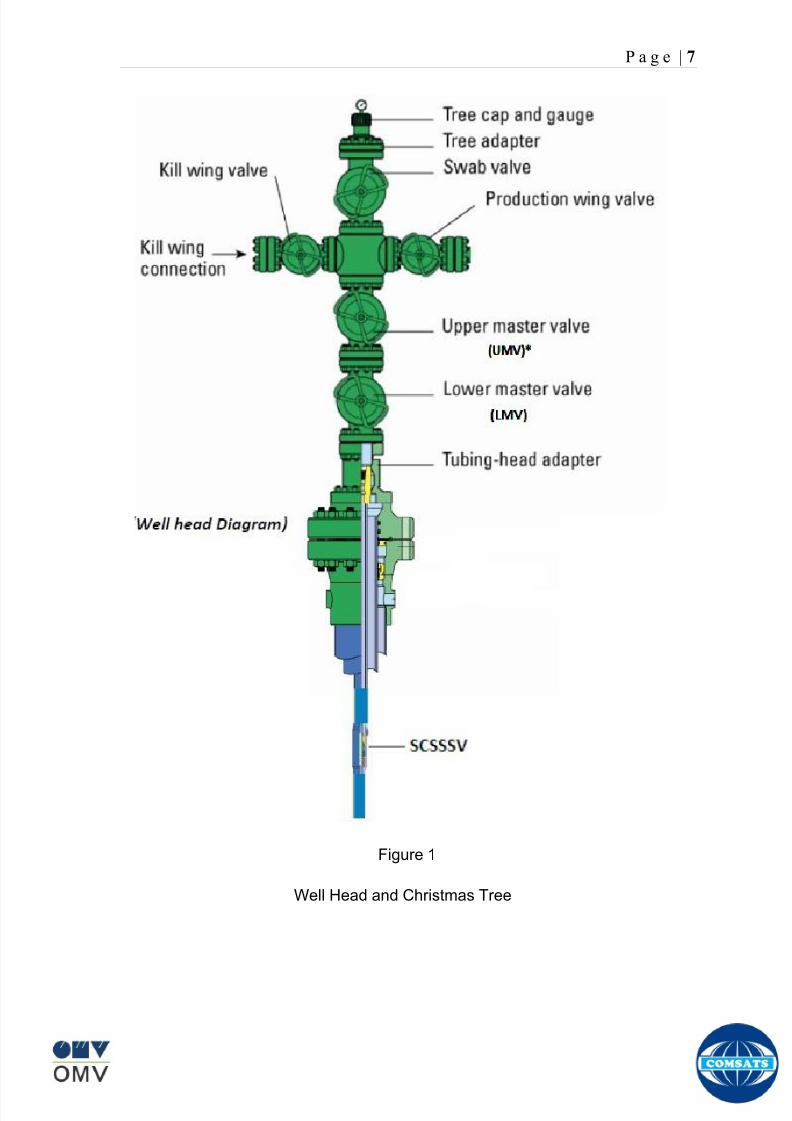
8102019 Gas sweetening Plant
httpslidepdfcomreaderfullgas-sweetening-plant 1162
P a g e | 7
Figure 1
Well Head and Christmas Tree
8102019 Gas sweetening Plant
httpslidepdfcomreaderfullgas-sweetening-plant 1262
P a g e | 8
Master Valves
The two lower valves are called the master valves Master valves are normally in
the fully open position and are never opened or closed when the well is flowing
(except in an emergency) to prevent erosion of the valve sealing surfaces They
are gate type valves
1 Lower Master Valve (LMV)
2 Upper Master Valve (UMV)
The lower master valve will normally be manually operated while the upper
master valve is often hydraulically actuated allowing it to be used as a means of
remotely shutting in the well in the event of emergency
Wing Valve
A wing valve is normally used to shut in the well when flowing thus preserving
the master valves for positive shut off for maintenance purposes The wing
valve can be a gate valve or ball valve Hydraulic operated wing valves are
usually built to be fail safe closed meaning they require active hydraulic pressure
to stay open This feature means that if control fluid fails the well will
automatically shut itself in without operator action
In Kadanwari well sites there is only one manually operated wing valve On the
other hand at Miano well sites there are two wing valves one being operated
manually and other hydraulically
Production Wing Valve
The right hand valve is often called the flow wing valve or the production wing
valve because it provides flow path for hydrocarbons to production facility
Kill wing valve
The left hand valve is often called the kill wing valve It is primarily used for
injection of fluids such as corrosion inhibitors or methanol to prevent hydrate
formation It is typically manually operated It can kill the well temporarily be
injection brine solution which provides a pressure head to well and temporarily
8102019 Gas sweetening Plant
httpslidepdfcomreaderfullgas-sweetening-plant 1362
P a g e | 9
suspends it for maintenance of well head Also it is used to permanently kill the
well A chemical is injected down the well that seals the piping down the well and
kills the well permanently
Swab valve
The swab valve is used to gain access to the well for wire line operations
intervention and other work over procedure On top of it is a tree adapter
and cap that will mate with various equipment For such operations a
lubricator is assembled up onto the top of the tree and the wire or coil is lowered
through the lubricator through swab valve and into the well This valve is typically
manually operated
Choke
A choke holds back pressure by restricting the flow opening at the well head This
is done to make better use of the gas for natural gas lift and to control the bottom-
hole pressure for recovery reasons
CHECK VALVE
The check is introduced in production flow line to prevent any reverse flow from
the line into the well It has a hinged flap which lifts to permit normal flow but
closes to prevent reverse flow
TOP ADAPTOR
The top adaptor is a fitting on top of the swab valve with a threaded connection
During normal well operations a pressure gauge is fitted to monitor flowing and
shut in wellhead pressures However during well service operations the cap can
be removed to allow installation of lubricators for wire-line operations
SCSSSV (Surface Control Sub Surface Safety Valve)
A subsurface safety valve is essentially a shutdown valve installed at the upper
wellbore for emergency shutdown to protect the production tubing and wellhead
in case of overpressure Subsurface safety valves can offer a barrier against flow
in the event of a wellhead collapse or other disastrous event Purpose of asubsurface safety valve (SSSV) is to avoid the ultimate disaster which can result
8102019 Gas sweetening Plant
httpslidepdfcomreaderfullgas-sweetening-plant 1462
P a g e | 10
in release of reservoir fluids to the surroundings This makes SSSV a very
important component of a well completion
A subsurface safety valve is typically a uni-directional flapper valve directed in
such a way that the flappers open downwards when pressure is applied from an
upward direction The flapper can only open in the downward direction So even if
high pressure is applied by the well fluids from a
downward direction a safety valve can remain
closed This makes a subsurface safety valve fail-
safe To open the valve hydraulic signal is sent from
the surface well control panel This hydraulic
pressure is responsible for keeping the flappers of
SSSV open and loss of hydraulic pressure result in
closing of the valve Thus wellbore can be isolated in
case of system failure or damage to the surface
facilities
Types of Christmas tree
There are two types of Christmas Tree
1 Solid block
2 Conventional
The solid block Christmas Tree has a central solid unit holding several valves
in a pre-constructed block Their advantage is the reduction in potential leak
paths and their higher pressure rating (Fig 2)
The conventional Christmas Tree is built up from individual valves bolted
together to form an assembly (Fig 3)
8102019 Gas sweetening Plant
httpslidepdfcomreaderfullgas-sweetening-plant 1562
P a g e | 11
Figure 2
Figure 3
8102019 Gas sweetening Plant
httpslidepdfcomreaderfullgas-sweetening-plant 1662
P a g e | 12
Wellhead Control Panel
Wellhead control panel is key equipment in oil amp gas industry to protect oilfield
facilities and environment from emergency incidents such as wellhead fire which
is one of main control systems to ensure oilfield oil production and transportation
to be safely operation according to international standards and national
regulation Wellhead control panel is composed of hydraulic power unit tubing amp
fitting and instrument valve and electrical control devices Hydraulic power unit
supply hydraulic resource to open and close safety valves including master
valves wing valves and SCSSSV
Its performs
Local OnOff SSV
Remote control SSV through RTU( remote terminal unit)
High-Low pressure sense shut-down automatically
Fusible Plug Anti-fire Shut-down automatically
Function of showing system pressure
Relief Valve shall be installed on each hydraulic circuit to prevent high
pressure
Function of showing hydraulic level and level switch for alarm
Function of defending pressure impact of system
Function of system pressure monitoring (by pressure transmitter of control
panel)
Function of remote emergency shut-down (by magnetic valve of control
panel)
Function of OnOff SSV monitoring (by pressure switch of control loop of
control panel)
8102019 Gas sweetening Plant
httpslidepdfcomreaderfullgas-sweetening-plant 1762
P a g e | 13
Chemical Injection
Chemical injection systems are commonly used in production facilities to prevent
or eliminate a wide range of problems that might negatively affect the production
flow It is done for flow assurance protection of process equipment such as
pipelines or to optimize processes in production facilities
Typical flow assurance chemicals are
Wax inhibitors
Pour point depressants
Asphaltene inhibitors
Corrosion inhibitors
A corrosion inhibitor is a chemical compound that is added to liquid or gas to
decreases the corrosion rate of a material typically a metal or an alloy The
effectiveness of a corrosion inhibitor depends on fluid composition quantity of
water and flow regime Its common mechanism involves formation of a coating
8102019 Gas sweetening Plant
httpslidepdfcomreaderfullgas-sweetening-plant 1862
P a g e | 14
which prevents access of the corrosive substance to the metal The corrosive
agents are generally oxygen hydrogen sulfide and carbon dioxide
At our production site the major risk is corrosion of piping and equipment The
maximum allowable corrosion rate is approximately 02 mm per year and
corrosion rate without inhibitor could be approximately 11 mm per year so the
corrosion protection program is designed to achieve a target corrosion rate of
less than 01 mm per year which is achieved by an inhibitor system efficiency of
99 Inhibitor is injected into the well stream flow through an atomizing nozzle
located downstream of the respective wellhead coolers at the duplexcarbon steel
interface In normal operation as per NALCO standards chemical (brand name
EC1144B) at rate of frac12 Liter per MMSCFD of gas is being injected into the flow
line of miano15 flow lines made of carbon steel Moreover the composition can
vary depending upon the composition of well fluids and material of pipeline This
method of injection ensures even distribution of the chemical on the interior
surface of the pipeline The individual well sites are equipped with Chemical
Injection Packages comprising of a stainless steel storage tank and two
pneumatic motor driven pumps in parallel Instrument gas is used to drive the
pumps Normally one pump is running with the other standby
Water Conning
Water coning is a term used to describe the mechanism underlying the upward
movement of water into the perforations of a producing well Coning can seriously
impact the well productivity and influence the degree of depletion and the overall
recovery efficiency of the reservoir The specific problems of water coning are
listed below
Costly added water handling
Gas production from the original or secondary gas cap reduces pressure
Reduced efficiency of the depletion mechanism
The water is often corrosive and its disposal costly
The affected well may be abandoned early
Loss of the total field overall recovery
8102019 Gas sweetening Plant
httpslidepdfcomreaderfullgas-sweetening-plant 1962
P a g e | 15
Therefore conning has an important influence on operations recovery and
economics The phenomena is shown in picture below
Corrosion
Corrosion is referred as chemical deterioration of a metal Commonly this
means loss of electrons of metals reacting with water and oxygen
Weakening of iron due to oxidation of the iron atoms is a well-known
example of electrochemical corrosion This is commonly known as
rust Most structural alloys corrode merely from exposure to moisture
in the air but the process can be strongly affected by exposure to
certain substances Corrosion can be concentrated locally to form a pit
or crack or it can extend across a wide area to produce general
deterioration (uniform corrosion)
The following reaction takes place at the active sites
2Fe =gt 2Fe++ + 4e-
The free electrons travel through the metal path to the less active sites where
the following reaction takes place
O2 + 4e- + 2H20 =gt 4 OH-
8102019 Gas sweetening Plant
httpslidepdfcomreaderfullgas-sweetening-plant 2062
P a g e | 16
Recombination of these ions at the active surface produce the following
reaction which yields the iron-corrosion product ferrous hydroxide
2Fe + O2 + 2H2O =gt 2Fe (OH) 2
CORROSION PROTECTION SYSTEM
Coatings and painting
Painting and the application of enamel bitumen and PVC
coating are the most common anti-corrosion treatments They
work by providing a barrier of corrosion-resistant material
between the damaging environment and the structural material
Corrosion Inhibitors
Corrosion inhibitor is injected into the flow lines as mentioned in
detail on page 8
Cathodic Protection
Cathodic Protection (CP) is a technique used to control the corrosion of a
metal surface by making it the cathode of an electrochemical cell It
converts all of the anodic (active) sites on the metal surface to cathodic
(passive) sites by supplying electrical current (or free electrons) from an
alternate source It is accomplished in two ways
a) A simple method of protection connects protected metal to a more easily
corroded sacrificial metal to act as the anode The sacrificial metal then
corrodes instead of the protected metal The process is similar to a simple
DC cell in which the more active metal becomes the anode and corrodes
whereas the less active metal becomes the cathode and is protected
b) For larger structures galvanic anodes cannot economically deliver enough
current to provide protection Therefore impressed current cathodic
protection (ICCP) systems are used These consist of anodes connected
to a DC power source In remote areas power sources such as solar
panels may be used The output DC negative terminal is connected to the
8102019 Gas sweetening Plant
httpslidepdfcomreaderfullgas-sweetening-plant 2162
8102019 Gas sweetening Plant
httpslidepdfcomreaderfullgas-sweetening-plant 2262
P a g e | 18
frequently to limit liquid holdup and minimize the slug volumes of liquid which can
be generated by the system
Coating
Pigs may be used to apply internal pipe coatings such as epoxy coating
materials in operating pipelines Pigs may also be used with corrosion inhibitors
to distribute and coat the entire internal wetted perimeter
Inspection
Pigs are being used more frequently as inspection tools Gauging or sizing pigs
are typically run following the completion of new construction or line repair to
determine if there are any internal obstacles bends or buckles in the pipe Pigs
can also be equipped with cameras to allow viewing of the pipe internals
Electronic intelligent or smart ldquopigsrdquo that use magnetic and ultrasonic systems
have been developed and refined that locate and measure internal and external
corrosion pitting dents buckles and any other anomalies in the pipe wall
Intelligent pigs
The accuracy of location and measurement of anomalies by the intelligent pigs
has continued to improve Initially the electronics and power systems were so
large that intelligent pigs could be used only in lines 30 in and greater in size
The continued sophistication and miniaturization of the electronic systems used
in the intelligent pigs has allowed the development of smaller pigs that can be
used in small-diameter pipelines Newly enacted DOT pipeline-integrity
regulations and rules acknowledge the effectiveness of the intelligent pigs and
incorporate their use in the pipeline-integrity testing process
Compressors
A gas compressor is a mechanical device that increases the pressure of a gas by
reducing its volume Gas pressure is increased by forcing gas molecules together
to reduce gas volume When volume is reduced gas pressure increases
All gases have large spaces among their molecules These spaces could be
enhanced further and decreased by doing some work Work done which is used
8102019 Gas sweetening Plant
httpslidepdfcomreaderfullgas-sweetening-plant 2362
P a g e | 19
for the enhancement of these spaces is called expansion and work done to
minimize these spaces is called compression All gases while expansion
produces cooling effect and while compression of gases raises there
temperature Compression is a term used to force gases to occupy smaller
volumes by increasing their pressure Volume of gases is interlinked with
temperature and pressure of the gas which is cleared by 2 laws govern gas
compressions
Boyles Law
Charles Law
The main types of compressor are listed below
Front End Compressor
The plant currently processes gas from a number of wells The flow and pressure
from some of these wells (currently K-10 K-11 amp K-12) has declined and they
cannot be fed directly into the Central Processing Facility To recover the
maximum gas reserves from these wells a Front End Compressor is employed
The compressor is a two stage double acting gas engine driven reciprocating
(PT) compressor Double acting means that gas is compressed on each end of
the piston It normal operates with a speed range of 600 to 900 RPM and isequipped with four compressor cylinders two for each stage Each cylinder is
8102019 Gas sweetening Plant
httpslidepdfcomreaderfullgas-sweetening-plant 2462
P a g e | 20
also equipped with a variable volume head end pocket
In case of compressor emergency shutdown the production chokes and the
Upper Master Valves on the on line wells will close and operator will be notified in
central control room Sweet gas from gas distribution network is used to operate the
gas engine driver of the compressor package The detailed scheme of working is
shown in figure (page 22 )
PT Reciprocating Compressor
The mechanical cycle of piston tube reciprocating compressor comprises four
strokes the expansion stroke the intake stroke the compression stroke and the
discharge stroke
Expansion Stroke
As the piston moves back on the expansion stroke the chamber volume
increases and the pressure drop As the pressure drops the discharge valve
closes since there is greater pressure in the discharge line than in the chamber
Intake Stroke
As the piston moves back during the intake stroke the pressure decreases until it
is less than the pressure in the inlet line This higher intake pressure opens the
inlet valve and gas rushes into the cylinder equalizing the pressure there with
the intake pressure The compression chamber is now at or near the intake
pressure
Compression Stroke
The piston now starts the compression stroke by moving forward decreasing the
chamber volume and increasing the pressure The increased pressure is now
higher than the intake pressure causing the intake valve to close
Discharge Stroke
The piston continues to move to the left during the discharge stroke This creates
an increase in chamber pressure until it is greater than the discharge pressure
When this happens the Discharge valve opens and the compressed air from the
8102019 Gas sweetening Plant
httpslidepdfcomreaderfullgas-sweetening-plant 2562
P a g e | 21
cylinder goes into the discharge line The compression cycle is then repeated
from the stage
Compressor Capacity
The capacity of the compressor depends upon cylinder displacement That
displacement is simply the volume that the piston displaces (moves) as it travels
from one end of the cylinder to the other Capacity and displacement is equal to
the cross-sectional area of the cylinder times the length of the stroke
Lubrication and Cooling
Lubricating oil is circulated through the system by a gear pump which is chain
driven from the engine crank shaft The oil pump is mounted on the engine front
housing
The pump operates between 30 - 40 psig
8102019 Gas sweetening Plant
httpslidepdfcomreaderfullgas-sweetening-plant 2662
P a g e | 22
A circulating pump deliver cooling water to the water jackets in the cylinder block
flowing around the cylinder liners and is directed into the cylinder heads Each
cylinder head has water cooled exhaust elbows which outlet the water into the
water cooled exhausts From the end of engine the water flows to compressor
1st and 2nd stage cylinders and compressor lube oil cooler (LOwater heat
exchanger) The water from the compressor cylinder and lube oil cooler returns
to engine water cooled exhaust
Figure Flow diagram of Front End Compressor
8102019 Gas sweetening Plant
httpslidepdfcomreaderfullgas-sweetening-plant 2762
P a g e | 23
Centrifugal Compressor
Centrifugal compressors are machines in which velocity and pressure given to air
or gas in a radial direction by one or more impellers diffuser combination In a
centrifugal compressor the mechanical energy is increased by centrifugal action
The gas enters the suction eye of a high speed rotary element called the impeller
which carries radial vanes integrally cast in it As the impeller rotates the blades
of the impeller force the gas outward from the center the impeller to the outer rim
of impeller the increase in velocity of the gas creates a flow pressure area at the
eye of the impeller The gas at the outer rim of the impeller is forced in to a
passage way called a diffuser where the velocity decreases in the pressure of the
gas
Inlet
The inlet to a centrifugal compressor is typically a simple pipe It may include
features such as a valve and both pressure and temperature instrumentation
Centrifugal impeller
The key component that makes a compressor centrifugal is the centrifugal
impeller shown above It is the impellers rotating set of vanes (or blades) that
gradually raises the energy of the working gas This is identical to an axial
compressor with the exception that the gases can reach higher velocities and
energy levels through the impellers increasing radius
8102019 Gas sweetening Plant
httpslidepdfcomreaderfullgas-sweetening-plant 2862
P a g e | 24
Diffuser
The next key component to the simple centrifugal compressor is the diffuser
Downstream of the impeller in the flow path it is the diffusers responsibility to
convert the kinetic energy (high velocity) of the gas into pressure by gradually
slowing (diffusing) the gas velocity
SEPERATORS
A well-stream is a mixture of gases hydrocarbon liquids water solids and
contaminants Due to variations in pressure and temperature gases evolve from
the liquids water vapor condenses and some of the well-stream changes to liquid
and free gas The separation of well-stream fluids takes place in a separator This
pressure vessel is manufactured in three forms
1 horizontal
2 vertical
3 spherical
To help separation the vessel is normally designed with a series of internal
fittings These fittings are built into the separator to ensure total phase separation
of the well-stream
In gas plants separators are given alternative names due to the function they
perform in the process system A scrubber does a similar job to a knockout drum
However the scrubber usually separates a stream containing high gas-to-liquid
ratios The knockout drum is used where a high degree of liquids are entrained in
the gas
Fluid flow from a well can include gas condensable liquid vapors water water
vapor crude oil and solids As well-stream fluids reach ground level where
pressure is lower than in the reservoir the capacity of the liquid to hold gas in
solution decreases and gas separates out of the oil
Separation depends upon the effect of gravity to separate liquids For adequate
separation one fluid must be lighter than the other fluid For example distillates
8102019 Gas sweetening Plant
httpslidepdfcomreaderfullgas-sweetening-plant 2962
P a g e | 25
(gasoline kerosene etc) and crude oil will not separate in a vessel because they
tend to dissolve in each other Because a separator basically depends upon
gravity to separate the fluids the ease with which separation takes place
depends upon the difference in density of the fluids
Droplets of liquid will separate from gas provided
a) The gas remains in the separator long enough
b) The gas flow remains constant to provoke separation
The difference in density between a gas and liquid will therefore determine the
maximum flow rate of liquid in the vessel
Figure Two phase horizontal separator
Gas bubbles in the liquid will break out in some oil field applications in 30 to 60
seconds Consequently the separator is designed so that the liquid remains in
the vessel for 30 to 60 seconds The length of time that a liquid remains in the
vessel is called its residence time Residence time differs widely from field to field
depending upon viscosity and API Gravity
Another important factor which must be considered is temperature Generally a
decrease in operating temperature will increase the liquid recovery in a separator
8102019 Gas sweetening Plant
httpslidepdfcomreaderfullgas-sweetening-plant 3062
P a g e | 26
as the gas condenses By reducing the pressure on the fluid flash separation
occurs resulting in a flow through the separator which is controlled by external
instrumentation
COALESCENCE
Another important principle in fluid separation is that of coalescence This means
the coming together of liquid droplets created by the force of gravity
A common example of coalescing occurs when drops of water form on the
windshield of a car as it is driven in fog As the tiny drops or water which make up
the fog strike the windshield they combine and eventually form a drop large
enough to run down the glass
Several of the internal devices of a separator such as deflector plates
straightening vanes and even the vessel walls are forms of coalescers In each
vessel drops of liquid adhere to the surface of the device and combine with other
8102019 Gas sweetening Plant
httpslidepdfcomreaderfullgas-sweetening-plant 3162
P a g e | 27
drops until the drop is large enough to fall out The effectiveness of separation
will also depend upon the total amount of coalescing surface area that is present
There are many different types of separators used in the Oil amp Gas industry
Consequently separators are manufactured with one two or several internal
fittings depending on their use and quick removal of these fluids from the vessel
DEFLECTOR PLATES
These are fitted in front of the inlet to the separator and can be net or
dish-shaped Their purpose is to absorb the impact of the incoming fluids and to
encourage the separation of gas and liquids They also slow the flow rate of the
liquids through the vessel
WEIRS
A weir is a metal wall which is fitted across the inside of the vessel normally to a
height of 50 of the overall height of the separator Its purpose is to assist the
process of three phase separation The inlet fluids (oil plus water) are given time
to separate in the liquid accumulation section The water level (interface) is
normally controlled at 50 of the height of the weir Oil floating on the wateroverflows the weir and accumulates in the small oil compartment where it is
drawn off under level control
CENTRIFUGAL DEVICES
These are used in both vertical and horizontal separators for gas-liquid
separation The device imparts a swirling motion to the fluids entering the vessel
Centrifugal force causes the heavier liquids to travel outwards towards the walls
of the vessel and the lighter gases to flow up the centre Centrifugal devices are
also known as cyclones
VORTEX BREAKERS
When liquid flows through a drain outlet a vortex (whirlpool) will form This can
be seen when we pull the plug from a sink or bath tub The same would happen
as water and oil flow from the separator This condition a vortex could allow gas
to flow down the centre of the whirlpool and enter the liquid phase causing
8102019 Gas sweetening Plant
httpslidepdfcomreaderfullgas-sweetening-plant 3262
P a g e | 28
pressurizing of tanks etc To stop this happening vortex breakers are fitted to all
liquid outlets Although they come in a number of different designs vortex
breakers all serve the same purpose - to prevent a whirlpool from forming
MIST OR DEMISTER PADS
The gas which is released from the fluids in the separator still contains droplets of
oil and water which coalesce and fall when the drops get large enough The
demister pad assists in this process Made from knitted wire and contained within
a sturdy frame it causes the gas to continually change its direction of flow
Because gas changes direction far easier than liquid the gas will flow around
each strand of wire whilst the liquid entrained in the gas stream will continue and
stick to the wire
COALESCING PLATES
There are several different forms of coalescing devices the most common of
which are coalescing plates These plates are mounted in the flow stream of the
fluids and assist in breaking down oil-water emulsions The fluid is forced to
follow a path that constantly changes direction This causes the water droplets to
gather together or coalesce and fall to the bottom of the separator The same
principle is used to separate gas and oil mixtures when the oil droplets are
induced to coalesce Simply stated every surface within the separator including
the separator walls assists with the coalescing process
STRAIGHTENlNG VANES
These are often fitted to horizontal separators to remove turbulence in the gas
stream after initial separation at the inlet deflector
FLOAT SHEILD
Internal floats are used as level controllers Any agitation of the liquid surface or
the effect of coalesced liquids falling on the float may cause control problems
Therefore a float shield is fitted to enclose the float creating an area of still liquid
8102019 Gas sweetening Plant
httpslidepdfcomreaderfullgas-sweetening-plant 3362
P a g e | 29
MEMBRANES
The gas contains 12 carbon dioxide and 22 ppm of hydrogen sulphide at 115oF
and 1100 psig This needs to be removed before the gas can be exported The
majority of carbon dioxide hydrogen sulphide and water is removed by means of
membranes
Membranes are thin semipermeable barriers that selectively separate some
compounds from others Currently the only commercially workable membranes
used for CO2 removal are polymer based for example cellulose acetate
polyimides polyamides polysulfone polycarbonates and polyetherimide The
membrane does not operate as a filter where small molecules are separated
from larger ones through a medium with pores rather it separates based on how
well different compounds dissolve into the membrane and diffuse through it The
membranes are manufactured in flat sheets consisting of an extremely thin
nonporous layer mounted on a much-thicker and highly porous layer of the same
material providing mechanical strength The flat sheets are combined into a
spiral-wound element (Figure below) Feed gas enters along the side of the
membrane and passes through the feed spacers As the gas travels between
membrane sheets CO2 H2S and H2O permeate through the membrane and are
collected in the permeate tube The driving force for transport is the high-feed
pressure and low-permeate pressures The gas on the feed side that does not
permeate leaves through the side of the element opposite the feed position Once
the membranes have been manufactured into elements six to 12 elements are
joined together and inserted into a tube Multiple tubes are mounted on skids in a
horizontal orientation
8102019 Gas sweetening Plant
httpslidepdfcomreaderfullgas-sweetening-plant 3462
P a g e | 30
Figure Membrane general Working
In high H2S applications most polymers have been shown to have very little
resistance to H2S plasticization (ldquosofteningrdquo of the membrane) and as a
consequence can only be used at very low H2S partial pressure limits Cellulose
acetate membranes in contrast have been shown to be applicable at extreme
H2S partial pressure conditions It is these membranes that have been utilized in
the testing to determine the limits of membrane performance in high H 2S
applications
The primary membranes used in Kadanwari facility are Cellulose acetate
Cellulose acetic acid and acetic anhydride are mixed together and reacted to
form cellulose acetate polymers This process is aided by the addition of a small
amount of sulfuric acid which is subsequently neutralized during processing
However the membranes are bought from UOP (vendor) and installed for use
8102019 Gas sweetening Plant
httpslidepdfcomreaderfullgas-sweetening-plant 3562
P a g e | 31
How membrane work
The basic principle of separation is selectivity of certain components of a mixture
for the membrane For example the cellulose acetate membrane has very high
selectivity for CO2 and H2S as compared to CH4 Therefore such type of
membrane can be used in gas sweetening process
The selectivity is directly related to the Permeability of gas which accounts that
which gas can pass across the membrane more easily In simple words
membranes being polymer materials are made of long chains of molecules The
different structure of polymer materials only allow selective molecules to pass
through them depending upon chemical and physical compatibility Thus
permeability depends upon choice of polymer
The permeability is determined by permeability coefficient (P) and is product of
solubility (S) and diffusivity (D)
P = S D
Solubility
The solubility is mainly determined by ease of condensation Heavy molecules
are more readily condensed Therefore higher molecular weighted molecules will
more easily condensed and therefore have greater solubility
Molecule Molecular weight
CH4 16
H2S 34
CO2 44
8102019 Gas sweetening Plant
httpslidepdfcomreaderfullgas-sweetening-plant 3662
P a g e | 32
Diffusivity
Diffusivity is ease of molecule to penetrate into some material It depends on size
of gas molecule Here size of molecule is not to be confused by molecular weight
it is the size of the structure Eg the size of O2 molecule is smaller than N2
Molecule Molecular Diameter (Ao)
CO2 33
H2S 36
Ch4 40
For cellulose acetate
DCO2DCH4 S CO2S CH4 P CO2P CH4
45 73 308
Chemical degradation
Cellulose acetate polymer is chemically degraded by a process called hydrolysis
which means breaking apart by the addition of water This is a chemical reaction
in which water is added to the cellulose acetate polymer causing the release of
acetic acid molecules This process proceeds stepwise until all the acetate
groups are released resulting in the reformation of cellulose Moreover alcohols
aromatic hydrocarbons or solvents with chlorine nitro benzene or similar
aromatic solvents will harm the membrane It will expand and lose plastification in
contact with them
Effect of Temperature
The permeation rates of all gases increases with increasing temperature
however membrane selectivity for CO2 over hydrocarbon decreases at higher
8102019 Gas sweetening Plant
httpslidepdfcomreaderfullgas-sweetening-plant 3762
P a g e | 33
temperature Consequently CO2 removal will improve as operating temperature
increases but hydro carbon recovery will decrease
Primary Membrane
The primary membranes comprise of two trains Each train consists of two
sections AB and CD each section consists of a 30 tube membrane skid (A and
C) followed by a 25 tube skid (B and D) The conditioned gas (after pre-
treatment) enters the primary membrane via the particulate filter adjacent to the
skid The gas is fed to the membranes through a common inlet manifold which
supplies primary membranes skids A and C A pressure control loop located
upstream of the manual inlet isolation valve is provided to maintain a constant
supply pressure to the membrane skid and to allow for preheating at the inlet
prior to skid start-up This pressure control loop can also be used during start-up
to control the pressurization of the pretreatment skid and associated pipes to the
primary membranes
The gas passes through membrane skid A the residual gas exiting the membrane
skid is sent to skid B and the permeate to common permeate discharge header An
identical arrangement is provide on the inlet to skid C as provided on skid A Theresidual gas from skid B combines with the residual gas from skid D in a common
discharge header and is then sent to the H2S polishing towers via the feed coolers
on the pre-treatment skid The permeate from skid B is sent to the common
permeate discharge header The permeate discharge header sends the gas to
either the recycle compressor or the vent header via a pressure control loop
Overpressure protection for the membranes is provided by a pressure safety valve
on the supply header to the membrane banks
8102019 Gas sweetening Plant
httpslidepdfcomreaderfullgas-sweetening-plant 3862
P a g e | 34
Secondary (Recycle) Membrane
The recycle membranes comprise of a single train with two skids each with four
banks of membrane tubes The conditioned gas from the discharge of the recycle
pre-treatment skid is routed to the first recycle membrane skid The gas passes
through the membranes the residual gas is fed to primary membrane (skid A) inlet
via feed gas cooler and permeate to the common permeate discharge header An
identical arrangement is provide on the inlet to skid B Permeate from the recycle
membrane skids A and B is routed to the vent header Some portion of permeate is
heated and sent for regeneration in Mem-Guard units Nitrogen purge can be
connected downstream of the inlet isolation valve on each skid to enable the
membrane tubes to be purged and left pressurized during prolonged shutdown
8102019 Gas sweetening Plant
httpslidepdfcomreaderfullgas-sweetening-plant 3962
P a g e | 35
Figure Flow Diagram of Recycle membrane unit
8102019 Gas sweetening Plant
httpslidepdfcomreaderfullgas-sweetening-plant 4062
P a g e | 36
ADVANTAGES OF MEMBRANE SYSTEMS
Membrane systems have major advantages over more-traditional methods of
acid gas removal
Lower capital cost Membrane systems are skid mounted and so the
scope cost and time taken for site preparation are minimal Installation
costs are significantly lower than alternative technologies especially for
remote areas Furthermore no additional facilities for solvent storage and
water treatment needed by other processes are required
Lower operating costs The only major operating cost for single-stage
membrane systems is membrane replacement This cost is significantly
lower than the solvent replacement and energy costs associated with
traditional technologies The improvements in membrane and
pretreatment design allow a longer useful membrane life which further
reduces operating costs The energy costs of multistage systems with
large recycle compressors are usually comparable to those for traditionaltechnologies
Deferred capital investment Often contracted sales-gas flow rates
increase over time as more wells are brought on-line With traditional
technologies the system design needs to take this later production into
account immediately and so the majority of the equipment is installed
before it is even needed The modular nature of membrane systems
means that only the membranes that are needed at start-up need be
installed The rest can be added either into existing tubes or in new skids
only when they are required
Operational simplicity and high reliability Because single-stage
membrane systems have no moving parts they have almost no
8102019 Gas sweetening Plant
httpslidepdfcomreaderfullgas-sweetening-plant 4162
P a g e | 37
unscheduled downtime and are extremely simple to operate They can
operate unattended for long periods of time The addition of a recycle
compressor adds some complexity to the system but still much less than
with a solvent- or adsorbent-based technology Multistage systems can be
operated at full capacity as single-stage systems when the recycle
compressor is down
Good weight and space efficiency Skid construction can be optimized
to the space available This space efficiency is especially important for
offshore environments where deck area is at a premium and is the
reason why so many new offshore developments have chosen to use
membranes for acid gas removal Figure 6 illustrates the space efficiency
of membrane systems The membrane unit in the lower left corner
replaced all the amine and glycol plant equipment shown in the rest of the
picture
Adaptability Because membrane area is dictated by the percentage of
acid gas removal rather than absolute acid gas removal small variations
in feed acid gas content hardly change the sales-gas acid gas
specification For example a system designed for 10 down to 3 acid
gas removal produces a 35 product from a 12 feed gas and a 5
product from a 15 feed gas
Design efficiency The membrane and pretreatment systems integrate a
number of operations such as dehydration CO2 and H2S removal dew-
point control and mercury removal Traditional acid gas removal
technologies require all of these operations as separate processes and
may also require additional dehydration because some technologies
saturate the product stream with water
8102019 Gas sweetening Plant
httpslidepdfcomreaderfullgas-sweetening-plant 4262
P a g e | 38
Power generation The permeate gas from membrane systems can be
used to provide fuel gas for power generation either for a recycle
compressor or other equipment
Ideal for debottlenecking Because expanding solvent- or adsorbent-
based acid gas removal plants without adding additional trains is difficult
an ideal solution is to use membranes for bulk acid gas removal and leave
the existing plant for final cleanup An additional advantage is that the
permeate gas from the membrane system can often be used as fuel for
the existing plant thus avoiding significant increase in hydrocarbon
losses
Environmentally friendly Membrane systems do not involve the
periodic removal and handling of spent solvents or adsorbents Permeate
gases can be flared used as fuel or re-injected into the well Items thatdo need disposal such as spent membrane elements can be incinerated
Ideal for remote locations Many of the factors mentioned above make
membrane systems a highly desirable technology for remote locations
where spare parts are rare and labor unskilled Furthermore solvents
storage and trucking water supply power generation or extensive
infrastructure are not required
Re-injection optimizations Since the permeate stream from the
membrane system can be operated at elevated pressures it is possible to
further pressurize by re-injection compression train
8102019 Gas sweetening Plant
httpslidepdfcomreaderfullgas-sweetening-plant 4362
P a g e | 39
Sorption
Sorption is a physical and chemical process by which one substance becomes
attached to another
It is of two main types
1 Absorption
2 Adsorption
Absorption
Absorption is a physical or chemical phenomenon or process in which atoms
molecules or ions enter some bulk phase ndash gas liquid or solid material This is a
different process from adsorption since molecules undergoing absorption are
taken up by the volume not by the surface (as in the case for adsorption)
Absorption process may be chemical (reactive) or physical (non-reactive)
Physical absorption
Physical absorption or non-reactive absorption is made between two phases ofmatter a liquid absorbs a gas or a solid absorbs a liquid
When a liquid solvent absorbs a gas mixture or part of it a mass of gas moves
into the liquid For example water may absorb oxygen from the air This mass
transfer takes place at the interface between the liquid and the gas at a rate
depending on both the gas and the liquid This type of absorption depends on the
solubility of gases the pressure and the temperature The rate and amount of
absorption also depend on the surface area of the interface and its duration in
time
When a solid absorbs a liquid mixture or part of it a mass of liquid moves into the
solid For example a clay pot used to store water may absorb some of the water
This mass transfer takes place at the interface between the solid and the liquid
at a rate depending on both the solid and the liquid
8102019 Gas sweetening Plant
httpslidepdfcomreaderfullgas-sweetening-plant 4462
P a g e | 40
Chemical absorption
Chemical absorption or reactive absorption is a chemical reaction between the
absorbed and the absorbing substances Sometimes it combines with physical
absorption This type of absorption depends upon the stoichiometry of the
reaction and the concentration of its reactants
Adsorption
Adsorption is the adhesion of atoms ions or molecules from a gas liquid or
dissolved solid to a surface This process creates a film of the adsorbate on the
surface of the adsorbent The binding to the surface is usually weak and
reversible Compounds with color and those that have taste or odor tend to bind
strongly Compounds that vibrate at frequencies in the visible spectrum are very
often are strongly adsorbed on activated carbon
The most common industrial adsorbents are activated carbon silica gel and
alumina because they present enormous surface areas per unit weight
Depending on the nature of attractive forces existing between the adsorbate and
adsorbent adsorption can be classified as
i) Physical adsorption
ii) Chemical adsorption
i) Physical adsorption (Physisorption)
In physical adsorption the forces of attraction between the molecules of the
adsorbate and the adsorbent are of the weak van der Waals type Since the
forces of attraction are weak the process of physisorption can be easily reversed
by heating or decreasing the pressure of the adsorbate (as in the case of gases)
8102019 Gas sweetening Plant
httpslidepdfcomreaderfullgas-sweetening-plant 4562
P a g e | 41
ii) Chemical adsorption (Chemisorption)
In chemisorption the forces of attraction between the adsorbate and the
adsorbent are very strong the molecules of adsorbate form chemical bonds with
the molecules of the adsorbent present in the surface
Adsorption is generally accompanied by release of energy that is most
adsorption processes are exothermic in nature Adsorption is a spontaneous
process therefore its free energy change is negative (∆Glt0) However the
entropy change associated with adsorption is generally negative because the
adsorbate molecules lose their translation freedom when they get attached to the
surface of the adsorbent Therefore in order for ∆G to be negative the enthalpy
change (∆H) must be sufficiently negative such that (∆G=∆H-T∆S) lt 0 This
explanation accounts for exothermic adsorption processes In cases where
endothermic adsorption occurs the entropy change ∆S is sufficiently positive
such that ∆G remains negative
Pre treatment
The main function of pretreatment skid is to provide membrane inlet specification
gas as mentioned by the vendor UOP It removes the contaminants that would
poison the membranes like dust solids (adsorbent particles) lube oil heavy
hydrocarbons etc It consists of
Feed Cooler
Feed Gas Scrubber
Filter Coalescer
Feed Gas Heater
Activated Carbon Guard Filter
Particle Filter
8102019 Gas sweetening Plant
httpslidepdfcomreaderfullgas-sweetening-plant 4662
8102019 Gas sweetening Plant
httpslidepdfcomreaderfullgas-sweetening-plant 4762
P a g e | 43
The regeneration is carried out by heated permeate gas from the recycle
membranes at 450oF The vessel is depressurized to 20 psi and heated gas is
introduced from top The gas carries out the adsorbed contaminants and leaves
the vessel from bottom cleaning the adsorbent This contaminated gas is burnt in
the flare
UOP the vendor of Memguard unit has never disclosed that what substance
MG3 and MG5 exactly are But as mentioned by vendor that both care class of
aluminosilicates Therefore MG3 can be potassium aluminosilicate and MG5 can
be Calcium aluminosilicate These are molecular sieves adsorbents Molecular
sieves are a microporous material which can selectively adsorb gases andliquids They are synthetic zeolites (crystalline metal aluminosilicates) which
upon dehydration can efficiently and selectively remove water or other
solvents The selectivity of a molecular sieve is determined by its pore size
molecules with a critical diameter which is less than the pore size will be
efficiently adsorbed while larger molecules will be excluded
8102019 Gas sweetening Plant
httpslidepdfcomreaderfullgas-sweetening-plant 4862
P a g e | 44
3A Molecular Sieve Adsorbent
The 3A molecular sieve adsorbent has a 3 angstrom (3A) pore size which means
that any molecule that is larger than the 3 angstrom pores will not be adsorbed
The 3A molecular sieve is the potassium type of A crystalline structure and is a
form of alkali Aluminosilicate For a 3A molecular sieve the sequence rate that
adsorption occurs is He Ne N and H2O
Due to the crystalline structure molecular sieves that have a 3 angstrom pore
size have a very high rate of adsorption and properties that promote a longer life
for products treated by the sieve The most common use for the 3A molecular
sieve is to remove water and moisture from materials that are in gas and liquid
form
5A Molecular Sieve Adsorbent
These are molecular sieve adsorbents with a pore size of 5 angstrom (5A) 5A
molecular sieves are unable to adsorb any molecules or impurities that are
smaller than 5A It is calcium form of type A crystalline structure and is form of analkali-aluminosilicate that is most commonly used to separate isomerous alkanes
from normal alkanes and to co-adsorb moisture and water along with carbon
dioxide from gases In additional 5A molecular sieves are used for gaseous
pressure swing adsorption (PSA)mdashthat is to separate particular gases from other
gases
Adsorption of nC4H10
Adsorption of nC4H10
Adsorption of C3H8 to C22H46
Adsorption of Freon-12 (dichlorodifluoromethane)
Natural gas drying
Normal- and iso-paraffin separation
Separation of aromatic
8102019 Gas sweetening Plant
httpslidepdfcomreaderfullgas-sweetening-plant 4962
P a g e | 45
Inlet Composition of Memguard vessel
COMPSOSITION MOLE
CARBON DIOXIDE 1096
MEHTANE 8593
ETHANE 173
PROPANE 023
I-BUTANE 008
N BUTANE 004
PENTANES 004
HEXANE + 000
NITROGEN 076
WATER 007
Outlet Composition of Memguard vessel
COMPSOSITION MOLE
CARBON DIOXIDE 1098
MEHTANE 8608
ETHANE 173
PROPANE 023
I-BUTANE 008N BUTANE 004
PENTANES 004
HEXANE + 000
NITROGENT 076
WATER 000
H2S polisher
The H2S polishing unit has been designed to treat 187 MMscfday of natural gas
containing up to 11 CO2 and 21 ppm H2S where the level of the CO2 and H2S
is reduced using a MemGuard Membrane separation unit The unit is situated
down-stream of the membrane unit and will further reduce the level of H2S in the
processed gas to a sales gas specification of 38 ppm
8102019 Gas sweetening Plant
httpslidepdfcomreaderfullgas-sweetening-plant 5062
P a g e | 46
This process uses three non-regenerable fixed bed absorber vessels using a low
temperature high activity absorbent The absorbent is a mixture of activated
metal oxides (mainly zinc oxide) The three towers can are generally operated in
parallel arrangement but on demand can be used in series (any of alternate
arrangements of A B C vessels) as shown in figure
The higher sales gas flow rate increased the catalyst consumption and
replacement frequency
ZnO + H2S =gt ZnS + H20
Routine samples are taken from the beds to provide a check on each bed
performance and to follow the saturation profile during the absorbent life After
the adsorbent has been fully utilized the adsorption vessels are recharged with
new adsorbent discarding the utilized one in a safe manner
109oF
1215 psig
Before H2S Polishing After H2S Polishing
8102019 Gas sweetening Plant
httpslidepdfcomreaderfullgas-sweetening-plant 5162
P a g e | 47
Figure
H2S Tower
Inlet pipe
4 Drums of 19mm
ceramic Balls
6 Micron mesh
5 Drums of 50mmceramic
1 Drums of19mm ceramic
01 Drums of6mm ceramic
112 drums of
Catalist ZnO
8102019 Gas sweetening Plant
httpslidepdfcomreaderfullgas-sweetening-plant 5262
P a g e | 48
Recycle Compressor
The permeate gas of the primary membrane unit carries recoverable amount of
CH4 It is fed to recycle membrane unit for further CH 4 recovery But the
permeate pressure from primary membranes which has been reduced to 12 psi
must be regenerated to 1200 psi for the gas to be fed again to the system For
this purpose we have employed recycle compressor The compressor is a four
stage centrifugal compressor It is driven by gas turbine of 31200 HP It has 25
MW producing capacity
Figure Recycle Compressor Process Flow Diagram
8102019 Gas sweetening Plant
httpslidepdfcomreaderfullgas-sweetening-plant 5362
P a g e | 49
Sales Gas Compressor
Gas from H2S polishing unit is sent to sales gas compressor where its pressure
is enhanced to 1100 psi so it may be injected to SNGPL high pressure trunk line
Sales gas compressor is single stage gas turbine driven
Figure Process Flow of Sales Gas Compressor
8102019 Gas sweetening Plant
httpslidepdfcomreaderfullgas-sweetening-plant 5462
P a g e | 50
Cooling Towers
A cooling tower is a heat rejection device which extracts waste heat to theatmosphere through the cooling of a water stream to a lower temperature Hot
water from the system enters the cooling tower and is distributed over the fill
(heat transfer surface) Air is induced or forced through the fill causing a small
portion of the water to evaporate This evaporation removes heat from the
remaining water which is collected in the cold water basin and returned to the
system to absorb more heat Each cooling tower line although operating under
the same basic principle of operation is arranged a little differently
Types
Natural draft mdash Utilizes buoyancy via a tall chimney Warm moist air naturally
rises due to the density differential compared to the dry cooler outside air Warm
moist air is less dense than drier air at the same pressure This moist air
buoyancy produces an upwards current of air through the tower
Mechanical draft mdash Uses power-driven fan motors to force or draw airthrough the tower
o Induced draft mdash A mechanical draft tower with a fan at the
discharge (at the top) which pulls air up through the tower The fan
induces hot moist air out the discharge This produces low entering
and high exiting air velocities reducing the possibility of
recirculation in which discharged air flows back into the air intake
o Forced draft mdash A mechanical draft tower with a blower type fan at
the intake The fan forces air into the tower creating high entering
and low exiting air velocities The low exiting velocity is much more
susceptible to recirculation This fanfill geometry is also known as
blow-through
8102019 Gas sweetening Plant
httpslidepdfcomreaderfullgas-sweetening-plant 5562
P a g e | 51
Forced Draft Cooling Tower Vs Induced Draft Cooling Tower
Induced Draft Cooling Tower have the ability to handle large water flow
rate than Forced Draft Cooling Tower
Induced Draft Cooling Tower is suitable for large cell sizes and fan sizes
as compared with Forced Draft Larger fan size may result in greater
efficiency and consequently lower power and sound level
Forced Draft Cooling Tower can be square or rectangular type only
however Induced Draft Cooling Towers can be round square or
rectangular type
Induced Draft Cooling Tower uses more compact ground area than Forced
Draft Cooling Tower equivalent capacity due to absence of fan on one
side
Fan equipment is warm exhaust air is less liable to icing up in winter
operation (Cold Countries)
Higher velocity in Forced Draft Cooling Tower cause drop in suspension
and cause additional static resistance to system
Configuration
There are two main configurations of factory assembled cooling towers crossflow
and counterflow In crossflow cooling towers the water flows vertically down the
fill as air flows horizontally across In counterflow cooling towers the water flows
vertically down the fill as air flows vertically up
Crossflow Configuration Counterflow Configuration
8102019 Gas sweetening Plant
httpslidepdfcomreaderfullgas-sweetening-plant 5662
P a g e | 52
Drift mdash Water droplets that are carried out of the cooling tower with the exhaust
air Drift droplets have the same concentration of impurities as the water entering
the tower The drift rate is typically reduced by employing baffle-like devices
called drift eliminators through which the air must travel after leaving the fill and
spray zones of the tower
Blow-out mdash Water droplets blown out of the cooling tower by wind generally at
the air inlet openings Water may also be lost in the absence of wind through
splashing or misting Devices such as wind screens louvers splash deflectors
and water diverters are used to limit these losses
Blow-down mdash The portion of the circulating water flow that is removed (usually
discharged to a drain) in order to maintain the amount of Total Dissolved Solids
(TDS) and other impurities at an acceptably low level Higher TDS concentration
in solution may result from greater cooling tower efficiency However the higher
the TDS concentration the greater the risk of scale biological growth and
corrosion
Make-up mdash The water that must be added to the circulating water system in
order to compensate for water losses such as evaporation drift loss blow-out
blow-down etc
Approach mdash The approach is the difference in temperature between the cooled-
water temperature and the entering-air wet bulb temperature
Range mdash The range is the temperature difference between the warm water inlet
and cooled water exit
Fill mdash Inside the tower fills are added to increase contact surface as well as
contact time between air and water to provide better heat transfer The efficiency
of the tower depends on the selection and amount of fill
8102019 Gas sweetening Plant
httpslidepdfcomreaderfullgas-sweetening-plant 5762
P a g e | 53
There are two types of fills that may be used
o Film type fill (causes water to spread into a thin film)
o Splash type fill (breaks up falling stream of water and interrupts its
vertical progress)
Important
Scale build up is controlled by adding chemicals to the cooling loop and diluting
the concentration by blow down and make-up Following chemicals are added to
the Cooling to control CorrosionSale and microbial growth
Corrosion Inhibitor To control corrosion in the Cooling system
Dispersant To kept ions in suspension to avoid settle down and buildup
Sodium hypo Chlorite To Control microbial Growth
Acid To control Alkalinity in the system
High Stress Polymer To run the system at higher conductivity It is a
multifunctional polymer for Zinc amp Phosphate stabilization in cooling tower
Fin Fan Cooler
Fin fan heat exchanger is simply a pressure vessel which cools a circulating fluid
within finned tubes by forcing ambient air over the exterior of the tubes A
common example of an air cooler is a carrsquos radiator Fin Fan Coolers are used in
any application where large quantities of heat need to be transferred This
includes chemical and petrochemical industries power stations waste-to-energy
facilities as well as steelworks
Fin Fan Cooler are used for two primary reasons
They increase plant efficiency
They are a green solution as compared to cooling towers and shell and
tube heat exchangers because they do not require an auxiliary water
8102019 Gas sweetening Plant
httpslidepdfcomreaderfullgas-sweetening-plant 5862
P a g e | 54
supply (water lost due to drift and evaporation plus no water treatment
chemicals are required)
Figure General Overview of Fin Fan Cooler
Produced Water
The produced water system receives liquid from the equipment Miano slug
catcher train 1 and 2 inlet separators and is fed to three phase separator where
water oil and gas is separated The gases produced are burnt in incinerator
whereas hydrocarbon liquid is stored to be sold Liquid from compressors
recycle inlet separator recycle feed scrubber high and low pressure slug
catchers is passed to degasser Separated water is injected down the earth
Incinerator
The term incinerate means to burn something until nothing is left but ashes An
incinerator is a unit or facility used to burn trash and other types of waste until it is
reduced to ash An incinerator is constructed of heavy well-insulated materials
so that it does not give off extreme amounts of external heat The high levels of
heat are kept inside the furnace or unit so that the waste is burned quickly and
efficiently If the heat were allowed to escape the waste would not burn as
completely or as rapidly
8102019 Gas sweetening Plant
httpslidepdfcomreaderfullgas-sweetening-plant 5962
P a g e | 55
Control System
The plant is controlled at CCR (Central Control Room) by PLCs (Programmable
Logic Controllers) through fiber optic control line All control parameters are
received at LER (Local Equipment Room) via two optic fiber control lines One
being primary and other secondary operating in redundancy ie if primary fails
control shifts to secondary These control parameters are sent to CCR via single
optic fiber cable
Safety System
Wellheads and Gas Processing Plant have their own Fire amp Gas detection
systems emergency shutdown (ESD) Plant has a fault tolerant controller It is
based on Triple Modular Redundant (TMR) architecture manufactured by
Triconex The TMR system is based on three isolated parallel control systems
integrated into one system The system operates on a two out of three voting
principle which provides high integrity error free uninterrupted operation with no
single point of failure The TMR receives inputs from Process Sensors Manual
Switches Fire amp Gas Detectors Packaged Equipment Control Systems and
Product Exporting Facilities The TMR carries out cause and effect processing on
the data received and where necessary produces output signals Outputs from
the TMR are hard wired directly to ESD shutdown and blow down valve
solenoids motor control instrumentelectrical interfaces to control electrical
drives package equipment logic control systems manifold area as well as
telecoms
The operator in central control room is able to accept alarms and once the fault
has been cleared reset the input All the control systems are centralized to a
single interface All the PLCs (Programmable Logic Controllers) communicate with
the servers and servers communicate with the clients through Ethernet connectivity
Centralization eases the navigation of different systems at a common interface
Emergency Shutdown
The ESD system receives inputs from field mounted instrumentation on the process
8102019 Gas sweetening Plant
httpslidepdfcomreaderfullgas-sweetening-plant 6062
P a g e | 56
and utility equipment and initiates executive actions appropriate to the level of ESD
The system is an Active system which is in standby and will activate when in an
alarm or fault condition The Kadanwari Gas Process Facility ESD system is
comprised of five (5) levels The emergency severity decreases with increasing ESD
level number
ESD 1
This shutdown level is automatically initiated by fire major gas leak or a detected
toxic atmosphere in the process area of the plant or manually from CCR A level 1
shutdown will cause all production to cease close all emergency shutdown
valves stop the process and shutdown of the main power generation The
emergency vent valves to the stack will open and in addition all equipment of zone 1
certified will be isolated This is the highest level of ESD and will cause the following
to occur
All Shutdown Valves (SDVs) on the process facility will close All slowdown Valves (BDVs) on the process facility will open
All Main Gas Driven Generators will be tripped
Emergency Diesel Generator will start
All electrical power to process and utility rotating equipment will be
isolated
Wellhead Choke Valves Close Wing Valves Close Upper Master Valve
(UMV) Close
ESD 2
This shutdown level is activated automatically if a major process or utility failure
occurs or manually from CCR All production to the plant from the wellhead is
stopped All emergency shutdown valves trip to their fail safe position
Venting shall be as specified This level of ESD will cause the following to occur
8102019 Gas sweetening Plant
httpslidepdfcomreaderfullgas-sweetening-plant 6162
P a g e | 57
All Shutdown Valves (SDVs) on the process facility will close
All electrical power to process and utility rotating equipment will be
isolated
Wellhead Choke Valve Close Wing Valves Close and Upper Master Valve(UMV) Close
ESD 3
The level 3 shutdown isolates and stops a single process train only Production
continues via the other train This ESD level is initiated by process conditions or
operator at local panel This level of ESD will cause the following to occur
ESD 3A Train 1 production to cease
ESD 3B Train 2 production to cease
All online wellhead choke valves go to minimum flow ie (1O )
ESD 4
A level 4 shutdown shall cease all production from an entire field either
Kadanwari or Miano upstream of the associated slug catchers ESD 4K for
Kadanwari amp ESD 4M for Miano This ESD level is initiated automatically by slug
catcher abnormal process conditions This level of ESD will cause the following
to occur
All SDVs close isolating the relevant slug catcher and its upstream gas
production facility from the Kadanwari Gas Processing Plant
All Wellhead Choke Valves Close Wing Valves Close and Upper MasterValves (UMV) of the relevant gas production facility Close
A parallel timer is provided to close within 10 second if not closed in given
time SSSV seals the well
ESD 5
A level 5 shutdown represents equipment shutdown for the protection of the
individual equipment without any change in the process This level of ESD is for the
protection of various pieces of equipment and is initiated by its own inputs eg
8102019 Gas sweetening Plant
httpslidepdfcomreaderfullgas-sweetening-plant 6262
8102019 Gas sweetening Plant
httpslidepdfcomreaderfullgas-sweetening-plant 1362
P a g e | 9
suspends it for maintenance of well head Also it is used to permanently kill the
well A chemical is injected down the well that seals the piping down the well and
kills the well permanently
Swab valve
The swab valve is used to gain access to the well for wire line operations
intervention and other work over procedure On top of it is a tree adapter
and cap that will mate with various equipment For such operations a
lubricator is assembled up onto the top of the tree and the wire or coil is lowered
through the lubricator through swab valve and into the well This valve is typically
manually operated
Choke
A choke holds back pressure by restricting the flow opening at the well head This
is done to make better use of the gas for natural gas lift and to control the bottom-
hole pressure for recovery reasons
CHECK VALVE
The check is introduced in production flow line to prevent any reverse flow from
the line into the well It has a hinged flap which lifts to permit normal flow but
closes to prevent reverse flow
TOP ADAPTOR
The top adaptor is a fitting on top of the swab valve with a threaded connection
During normal well operations a pressure gauge is fitted to monitor flowing and
shut in wellhead pressures However during well service operations the cap can
be removed to allow installation of lubricators for wire-line operations
SCSSSV (Surface Control Sub Surface Safety Valve)
A subsurface safety valve is essentially a shutdown valve installed at the upper
wellbore for emergency shutdown to protect the production tubing and wellhead
in case of overpressure Subsurface safety valves can offer a barrier against flow
in the event of a wellhead collapse or other disastrous event Purpose of asubsurface safety valve (SSSV) is to avoid the ultimate disaster which can result
8102019 Gas sweetening Plant
httpslidepdfcomreaderfullgas-sweetening-plant 1462
P a g e | 10
in release of reservoir fluids to the surroundings This makes SSSV a very
important component of a well completion
A subsurface safety valve is typically a uni-directional flapper valve directed in
such a way that the flappers open downwards when pressure is applied from an
upward direction The flapper can only open in the downward direction So even if
high pressure is applied by the well fluids from a
downward direction a safety valve can remain
closed This makes a subsurface safety valve fail-
safe To open the valve hydraulic signal is sent from
the surface well control panel This hydraulic
pressure is responsible for keeping the flappers of
SSSV open and loss of hydraulic pressure result in
closing of the valve Thus wellbore can be isolated in
case of system failure or damage to the surface
facilities
Types of Christmas tree
There are two types of Christmas Tree
1 Solid block
2 Conventional
The solid block Christmas Tree has a central solid unit holding several valves
in a pre-constructed block Their advantage is the reduction in potential leak
paths and their higher pressure rating (Fig 2)
The conventional Christmas Tree is built up from individual valves bolted
together to form an assembly (Fig 3)
8102019 Gas sweetening Plant
httpslidepdfcomreaderfullgas-sweetening-plant 1562
P a g e | 11
Figure 2
Figure 3
8102019 Gas sweetening Plant
httpslidepdfcomreaderfullgas-sweetening-plant 1662
P a g e | 12
Wellhead Control Panel
Wellhead control panel is key equipment in oil amp gas industry to protect oilfield
facilities and environment from emergency incidents such as wellhead fire which
is one of main control systems to ensure oilfield oil production and transportation
to be safely operation according to international standards and national
regulation Wellhead control panel is composed of hydraulic power unit tubing amp
fitting and instrument valve and electrical control devices Hydraulic power unit
supply hydraulic resource to open and close safety valves including master
valves wing valves and SCSSSV
Its performs
Local OnOff SSV
Remote control SSV through RTU( remote terminal unit)
High-Low pressure sense shut-down automatically
Fusible Plug Anti-fire Shut-down automatically
Function of showing system pressure
Relief Valve shall be installed on each hydraulic circuit to prevent high
pressure
Function of showing hydraulic level and level switch for alarm
Function of defending pressure impact of system
Function of system pressure monitoring (by pressure transmitter of control
panel)
Function of remote emergency shut-down (by magnetic valve of control
panel)
Function of OnOff SSV monitoring (by pressure switch of control loop of
control panel)
8102019 Gas sweetening Plant
httpslidepdfcomreaderfullgas-sweetening-plant 1762
P a g e | 13
Chemical Injection
Chemical injection systems are commonly used in production facilities to prevent
or eliminate a wide range of problems that might negatively affect the production
flow It is done for flow assurance protection of process equipment such as
pipelines or to optimize processes in production facilities
Typical flow assurance chemicals are
Wax inhibitors
Pour point depressants
Asphaltene inhibitors
Corrosion inhibitors
A corrosion inhibitor is a chemical compound that is added to liquid or gas to
decreases the corrosion rate of a material typically a metal or an alloy The
effectiveness of a corrosion inhibitor depends on fluid composition quantity of
water and flow regime Its common mechanism involves formation of a coating
8102019 Gas sweetening Plant
httpslidepdfcomreaderfullgas-sweetening-plant 1862
P a g e | 14
which prevents access of the corrosive substance to the metal The corrosive
agents are generally oxygen hydrogen sulfide and carbon dioxide
At our production site the major risk is corrosion of piping and equipment The
maximum allowable corrosion rate is approximately 02 mm per year and
corrosion rate without inhibitor could be approximately 11 mm per year so the
corrosion protection program is designed to achieve a target corrosion rate of
less than 01 mm per year which is achieved by an inhibitor system efficiency of
99 Inhibitor is injected into the well stream flow through an atomizing nozzle
located downstream of the respective wellhead coolers at the duplexcarbon steel
interface In normal operation as per NALCO standards chemical (brand name
EC1144B) at rate of frac12 Liter per MMSCFD of gas is being injected into the flow
line of miano15 flow lines made of carbon steel Moreover the composition can
vary depending upon the composition of well fluids and material of pipeline This
method of injection ensures even distribution of the chemical on the interior
surface of the pipeline The individual well sites are equipped with Chemical
Injection Packages comprising of a stainless steel storage tank and two
pneumatic motor driven pumps in parallel Instrument gas is used to drive the
pumps Normally one pump is running with the other standby
Water Conning
Water coning is a term used to describe the mechanism underlying the upward
movement of water into the perforations of a producing well Coning can seriously
impact the well productivity and influence the degree of depletion and the overall
recovery efficiency of the reservoir The specific problems of water coning are
listed below
Costly added water handling
Gas production from the original or secondary gas cap reduces pressure
Reduced efficiency of the depletion mechanism
The water is often corrosive and its disposal costly
The affected well may be abandoned early
Loss of the total field overall recovery
8102019 Gas sweetening Plant
httpslidepdfcomreaderfullgas-sweetening-plant 1962
P a g e | 15
Therefore conning has an important influence on operations recovery and
economics The phenomena is shown in picture below
Corrosion
Corrosion is referred as chemical deterioration of a metal Commonly this
means loss of electrons of metals reacting with water and oxygen
Weakening of iron due to oxidation of the iron atoms is a well-known
example of electrochemical corrosion This is commonly known as
rust Most structural alloys corrode merely from exposure to moisture
in the air but the process can be strongly affected by exposure to
certain substances Corrosion can be concentrated locally to form a pit
or crack or it can extend across a wide area to produce general
deterioration (uniform corrosion)
The following reaction takes place at the active sites
2Fe =gt 2Fe++ + 4e-
The free electrons travel through the metal path to the less active sites where
the following reaction takes place
O2 + 4e- + 2H20 =gt 4 OH-
8102019 Gas sweetening Plant
httpslidepdfcomreaderfullgas-sweetening-plant 2062
P a g e | 16
Recombination of these ions at the active surface produce the following
reaction which yields the iron-corrosion product ferrous hydroxide
2Fe + O2 + 2H2O =gt 2Fe (OH) 2
CORROSION PROTECTION SYSTEM
Coatings and painting
Painting and the application of enamel bitumen and PVC
coating are the most common anti-corrosion treatments They
work by providing a barrier of corrosion-resistant material
between the damaging environment and the structural material
Corrosion Inhibitors
Corrosion inhibitor is injected into the flow lines as mentioned in
detail on page 8
Cathodic Protection
Cathodic Protection (CP) is a technique used to control the corrosion of a
metal surface by making it the cathode of an electrochemical cell It
converts all of the anodic (active) sites on the metal surface to cathodic
(passive) sites by supplying electrical current (or free electrons) from an
alternate source It is accomplished in two ways
a) A simple method of protection connects protected metal to a more easily
corroded sacrificial metal to act as the anode The sacrificial metal then
corrodes instead of the protected metal The process is similar to a simple
DC cell in which the more active metal becomes the anode and corrodes
whereas the less active metal becomes the cathode and is protected
b) For larger structures galvanic anodes cannot economically deliver enough
current to provide protection Therefore impressed current cathodic
protection (ICCP) systems are used These consist of anodes connected
to a DC power source In remote areas power sources such as solar
panels may be used The output DC negative terminal is connected to the
8102019 Gas sweetening Plant
httpslidepdfcomreaderfullgas-sweetening-plant 2162
8102019 Gas sweetening Plant
httpslidepdfcomreaderfullgas-sweetening-plant 2262
P a g e | 18
frequently to limit liquid holdup and minimize the slug volumes of liquid which can
be generated by the system
Coating
Pigs may be used to apply internal pipe coatings such as epoxy coating
materials in operating pipelines Pigs may also be used with corrosion inhibitors
to distribute and coat the entire internal wetted perimeter
Inspection
Pigs are being used more frequently as inspection tools Gauging or sizing pigs
are typically run following the completion of new construction or line repair to
determine if there are any internal obstacles bends or buckles in the pipe Pigs
can also be equipped with cameras to allow viewing of the pipe internals
Electronic intelligent or smart ldquopigsrdquo that use magnetic and ultrasonic systems
have been developed and refined that locate and measure internal and external
corrosion pitting dents buckles and any other anomalies in the pipe wall
Intelligent pigs
The accuracy of location and measurement of anomalies by the intelligent pigs
has continued to improve Initially the electronics and power systems were so
large that intelligent pigs could be used only in lines 30 in and greater in size
The continued sophistication and miniaturization of the electronic systems used
in the intelligent pigs has allowed the development of smaller pigs that can be
used in small-diameter pipelines Newly enacted DOT pipeline-integrity
regulations and rules acknowledge the effectiveness of the intelligent pigs and
incorporate their use in the pipeline-integrity testing process
Compressors
A gas compressor is a mechanical device that increases the pressure of a gas by
reducing its volume Gas pressure is increased by forcing gas molecules together
to reduce gas volume When volume is reduced gas pressure increases
All gases have large spaces among their molecules These spaces could be
enhanced further and decreased by doing some work Work done which is used
8102019 Gas sweetening Plant
httpslidepdfcomreaderfullgas-sweetening-plant 2362
P a g e | 19
for the enhancement of these spaces is called expansion and work done to
minimize these spaces is called compression All gases while expansion
produces cooling effect and while compression of gases raises there
temperature Compression is a term used to force gases to occupy smaller
volumes by increasing their pressure Volume of gases is interlinked with
temperature and pressure of the gas which is cleared by 2 laws govern gas
compressions
Boyles Law
Charles Law
The main types of compressor are listed below
Front End Compressor
The plant currently processes gas from a number of wells The flow and pressure
from some of these wells (currently K-10 K-11 amp K-12) has declined and they
cannot be fed directly into the Central Processing Facility To recover the
maximum gas reserves from these wells a Front End Compressor is employed
The compressor is a two stage double acting gas engine driven reciprocating
(PT) compressor Double acting means that gas is compressed on each end of
the piston It normal operates with a speed range of 600 to 900 RPM and isequipped with four compressor cylinders two for each stage Each cylinder is
8102019 Gas sweetening Plant
httpslidepdfcomreaderfullgas-sweetening-plant 2462
P a g e | 20
also equipped with a variable volume head end pocket
In case of compressor emergency shutdown the production chokes and the
Upper Master Valves on the on line wells will close and operator will be notified in
central control room Sweet gas from gas distribution network is used to operate the
gas engine driver of the compressor package The detailed scheme of working is
shown in figure (page 22 )
PT Reciprocating Compressor
The mechanical cycle of piston tube reciprocating compressor comprises four
strokes the expansion stroke the intake stroke the compression stroke and the
discharge stroke
Expansion Stroke
As the piston moves back on the expansion stroke the chamber volume
increases and the pressure drop As the pressure drops the discharge valve
closes since there is greater pressure in the discharge line than in the chamber
Intake Stroke
As the piston moves back during the intake stroke the pressure decreases until it
is less than the pressure in the inlet line This higher intake pressure opens the
inlet valve and gas rushes into the cylinder equalizing the pressure there with
the intake pressure The compression chamber is now at or near the intake
pressure
Compression Stroke
The piston now starts the compression stroke by moving forward decreasing the
chamber volume and increasing the pressure The increased pressure is now
higher than the intake pressure causing the intake valve to close
Discharge Stroke
The piston continues to move to the left during the discharge stroke This creates
an increase in chamber pressure until it is greater than the discharge pressure
When this happens the Discharge valve opens and the compressed air from the
8102019 Gas sweetening Plant
httpslidepdfcomreaderfullgas-sweetening-plant 2562
P a g e | 21
cylinder goes into the discharge line The compression cycle is then repeated
from the stage
Compressor Capacity
The capacity of the compressor depends upon cylinder displacement That
displacement is simply the volume that the piston displaces (moves) as it travels
from one end of the cylinder to the other Capacity and displacement is equal to
the cross-sectional area of the cylinder times the length of the stroke
Lubrication and Cooling
Lubricating oil is circulated through the system by a gear pump which is chain
driven from the engine crank shaft The oil pump is mounted on the engine front
housing
The pump operates between 30 - 40 psig
8102019 Gas sweetening Plant
httpslidepdfcomreaderfullgas-sweetening-plant 2662
P a g e | 22
A circulating pump deliver cooling water to the water jackets in the cylinder block
flowing around the cylinder liners and is directed into the cylinder heads Each
cylinder head has water cooled exhaust elbows which outlet the water into the
water cooled exhausts From the end of engine the water flows to compressor
1st and 2nd stage cylinders and compressor lube oil cooler (LOwater heat
exchanger) The water from the compressor cylinder and lube oil cooler returns
to engine water cooled exhaust
Figure Flow diagram of Front End Compressor
8102019 Gas sweetening Plant
httpslidepdfcomreaderfullgas-sweetening-plant 2762
P a g e | 23
Centrifugal Compressor
Centrifugal compressors are machines in which velocity and pressure given to air
or gas in a radial direction by one or more impellers diffuser combination In a
centrifugal compressor the mechanical energy is increased by centrifugal action
The gas enters the suction eye of a high speed rotary element called the impeller
which carries radial vanes integrally cast in it As the impeller rotates the blades
of the impeller force the gas outward from the center the impeller to the outer rim
of impeller the increase in velocity of the gas creates a flow pressure area at the
eye of the impeller The gas at the outer rim of the impeller is forced in to a
passage way called a diffuser where the velocity decreases in the pressure of the
gas
Inlet
The inlet to a centrifugal compressor is typically a simple pipe It may include
features such as a valve and both pressure and temperature instrumentation
Centrifugal impeller
The key component that makes a compressor centrifugal is the centrifugal
impeller shown above It is the impellers rotating set of vanes (or blades) that
gradually raises the energy of the working gas This is identical to an axial
compressor with the exception that the gases can reach higher velocities and
energy levels through the impellers increasing radius
8102019 Gas sweetening Plant
httpslidepdfcomreaderfullgas-sweetening-plant 2862
P a g e | 24
Diffuser
The next key component to the simple centrifugal compressor is the diffuser
Downstream of the impeller in the flow path it is the diffusers responsibility to
convert the kinetic energy (high velocity) of the gas into pressure by gradually
slowing (diffusing) the gas velocity
SEPERATORS
A well-stream is a mixture of gases hydrocarbon liquids water solids and
contaminants Due to variations in pressure and temperature gases evolve from
the liquids water vapor condenses and some of the well-stream changes to liquid
and free gas The separation of well-stream fluids takes place in a separator This
pressure vessel is manufactured in three forms
1 horizontal
2 vertical
3 spherical
To help separation the vessel is normally designed with a series of internal
fittings These fittings are built into the separator to ensure total phase separation
of the well-stream
In gas plants separators are given alternative names due to the function they
perform in the process system A scrubber does a similar job to a knockout drum
However the scrubber usually separates a stream containing high gas-to-liquid
ratios The knockout drum is used where a high degree of liquids are entrained in
the gas
Fluid flow from a well can include gas condensable liquid vapors water water
vapor crude oil and solids As well-stream fluids reach ground level where
pressure is lower than in the reservoir the capacity of the liquid to hold gas in
solution decreases and gas separates out of the oil
Separation depends upon the effect of gravity to separate liquids For adequate
separation one fluid must be lighter than the other fluid For example distillates
8102019 Gas sweetening Plant
httpslidepdfcomreaderfullgas-sweetening-plant 2962
P a g e | 25
(gasoline kerosene etc) and crude oil will not separate in a vessel because they
tend to dissolve in each other Because a separator basically depends upon
gravity to separate the fluids the ease with which separation takes place
depends upon the difference in density of the fluids
Droplets of liquid will separate from gas provided
a) The gas remains in the separator long enough
b) The gas flow remains constant to provoke separation
The difference in density between a gas and liquid will therefore determine the
maximum flow rate of liquid in the vessel
Figure Two phase horizontal separator
Gas bubbles in the liquid will break out in some oil field applications in 30 to 60
seconds Consequently the separator is designed so that the liquid remains in
the vessel for 30 to 60 seconds The length of time that a liquid remains in the
vessel is called its residence time Residence time differs widely from field to field
depending upon viscosity and API Gravity
Another important factor which must be considered is temperature Generally a
decrease in operating temperature will increase the liquid recovery in a separator
8102019 Gas sweetening Plant
httpslidepdfcomreaderfullgas-sweetening-plant 3062
P a g e | 26
as the gas condenses By reducing the pressure on the fluid flash separation
occurs resulting in a flow through the separator which is controlled by external
instrumentation
COALESCENCE
Another important principle in fluid separation is that of coalescence This means
the coming together of liquid droplets created by the force of gravity
A common example of coalescing occurs when drops of water form on the
windshield of a car as it is driven in fog As the tiny drops or water which make up
the fog strike the windshield they combine and eventually form a drop large
enough to run down the glass
Several of the internal devices of a separator such as deflector plates
straightening vanes and even the vessel walls are forms of coalescers In each
vessel drops of liquid adhere to the surface of the device and combine with other
8102019 Gas sweetening Plant
httpslidepdfcomreaderfullgas-sweetening-plant 3162
P a g e | 27
drops until the drop is large enough to fall out The effectiveness of separation
will also depend upon the total amount of coalescing surface area that is present
There are many different types of separators used in the Oil amp Gas industry
Consequently separators are manufactured with one two or several internal
fittings depending on their use and quick removal of these fluids from the vessel
DEFLECTOR PLATES
These are fitted in front of the inlet to the separator and can be net or
dish-shaped Their purpose is to absorb the impact of the incoming fluids and to
encourage the separation of gas and liquids They also slow the flow rate of the
liquids through the vessel
WEIRS
A weir is a metal wall which is fitted across the inside of the vessel normally to a
height of 50 of the overall height of the separator Its purpose is to assist the
process of three phase separation The inlet fluids (oil plus water) are given time
to separate in the liquid accumulation section The water level (interface) is
normally controlled at 50 of the height of the weir Oil floating on the wateroverflows the weir and accumulates in the small oil compartment where it is
drawn off under level control
CENTRIFUGAL DEVICES
These are used in both vertical and horizontal separators for gas-liquid
separation The device imparts a swirling motion to the fluids entering the vessel
Centrifugal force causes the heavier liquids to travel outwards towards the walls
of the vessel and the lighter gases to flow up the centre Centrifugal devices are
also known as cyclones
VORTEX BREAKERS
When liquid flows through a drain outlet a vortex (whirlpool) will form This can
be seen when we pull the plug from a sink or bath tub The same would happen
as water and oil flow from the separator This condition a vortex could allow gas
to flow down the centre of the whirlpool and enter the liquid phase causing
8102019 Gas sweetening Plant
httpslidepdfcomreaderfullgas-sweetening-plant 3262
P a g e | 28
pressurizing of tanks etc To stop this happening vortex breakers are fitted to all
liquid outlets Although they come in a number of different designs vortex
breakers all serve the same purpose - to prevent a whirlpool from forming
MIST OR DEMISTER PADS
The gas which is released from the fluids in the separator still contains droplets of
oil and water which coalesce and fall when the drops get large enough The
demister pad assists in this process Made from knitted wire and contained within
a sturdy frame it causes the gas to continually change its direction of flow
Because gas changes direction far easier than liquid the gas will flow around
each strand of wire whilst the liquid entrained in the gas stream will continue and
stick to the wire
COALESCING PLATES
There are several different forms of coalescing devices the most common of
which are coalescing plates These plates are mounted in the flow stream of the
fluids and assist in breaking down oil-water emulsions The fluid is forced to
follow a path that constantly changes direction This causes the water droplets to
gather together or coalesce and fall to the bottom of the separator The same
principle is used to separate gas and oil mixtures when the oil droplets are
induced to coalesce Simply stated every surface within the separator including
the separator walls assists with the coalescing process
STRAIGHTENlNG VANES
These are often fitted to horizontal separators to remove turbulence in the gas
stream after initial separation at the inlet deflector
FLOAT SHEILD
Internal floats are used as level controllers Any agitation of the liquid surface or
the effect of coalesced liquids falling on the float may cause control problems
Therefore a float shield is fitted to enclose the float creating an area of still liquid
8102019 Gas sweetening Plant
httpslidepdfcomreaderfullgas-sweetening-plant 3362
P a g e | 29
MEMBRANES
The gas contains 12 carbon dioxide and 22 ppm of hydrogen sulphide at 115oF
and 1100 psig This needs to be removed before the gas can be exported The
majority of carbon dioxide hydrogen sulphide and water is removed by means of
membranes
Membranes are thin semipermeable barriers that selectively separate some
compounds from others Currently the only commercially workable membranes
used for CO2 removal are polymer based for example cellulose acetate
polyimides polyamides polysulfone polycarbonates and polyetherimide The
membrane does not operate as a filter where small molecules are separated
from larger ones through a medium with pores rather it separates based on how
well different compounds dissolve into the membrane and diffuse through it The
membranes are manufactured in flat sheets consisting of an extremely thin
nonporous layer mounted on a much-thicker and highly porous layer of the same
material providing mechanical strength The flat sheets are combined into a
spiral-wound element (Figure below) Feed gas enters along the side of the
membrane and passes through the feed spacers As the gas travels between
membrane sheets CO2 H2S and H2O permeate through the membrane and are
collected in the permeate tube The driving force for transport is the high-feed
pressure and low-permeate pressures The gas on the feed side that does not
permeate leaves through the side of the element opposite the feed position Once
the membranes have been manufactured into elements six to 12 elements are
joined together and inserted into a tube Multiple tubes are mounted on skids in a
horizontal orientation
8102019 Gas sweetening Plant
httpslidepdfcomreaderfullgas-sweetening-plant 3462
P a g e | 30
Figure Membrane general Working
In high H2S applications most polymers have been shown to have very little
resistance to H2S plasticization (ldquosofteningrdquo of the membrane) and as a
consequence can only be used at very low H2S partial pressure limits Cellulose
acetate membranes in contrast have been shown to be applicable at extreme
H2S partial pressure conditions It is these membranes that have been utilized in
the testing to determine the limits of membrane performance in high H 2S
applications
The primary membranes used in Kadanwari facility are Cellulose acetate
Cellulose acetic acid and acetic anhydride are mixed together and reacted to
form cellulose acetate polymers This process is aided by the addition of a small
amount of sulfuric acid which is subsequently neutralized during processing
However the membranes are bought from UOP (vendor) and installed for use
8102019 Gas sweetening Plant
httpslidepdfcomreaderfullgas-sweetening-plant 3562
P a g e | 31
How membrane work
The basic principle of separation is selectivity of certain components of a mixture
for the membrane For example the cellulose acetate membrane has very high
selectivity for CO2 and H2S as compared to CH4 Therefore such type of
membrane can be used in gas sweetening process
The selectivity is directly related to the Permeability of gas which accounts that
which gas can pass across the membrane more easily In simple words
membranes being polymer materials are made of long chains of molecules The
different structure of polymer materials only allow selective molecules to pass
through them depending upon chemical and physical compatibility Thus
permeability depends upon choice of polymer
The permeability is determined by permeability coefficient (P) and is product of
solubility (S) and diffusivity (D)
P = S D
Solubility
The solubility is mainly determined by ease of condensation Heavy molecules
are more readily condensed Therefore higher molecular weighted molecules will
more easily condensed and therefore have greater solubility
Molecule Molecular weight
CH4 16
H2S 34
CO2 44
8102019 Gas sweetening Plant
httpslidepdfcomreaderfullgas-sweetening-plant 3662
P a g e | 32
Diffusivity
Diffusivity is ease of molecule to penetrate into some material It depends on size
of gas molecule Here size of molecule is not to be confused by molecular weight
it is the size of the structure Eg the size of O2 molecule is smaller than N2
Molecule Molecular Diameter (Ao)
CO2 33
H2S 36
Ch4 40
For cellulose acetate
DCO2DCH4 S CO2S CH4 P CO2P CH4
45 73 308
Chemical degradation
Cellulose acetate polymer is chemically degraded by a process called hydrolysis
which means breaking apart by the addition of water This is a chemical reaction
in which water is added to the cellulose acetate polymer causing the release of
acetic acid molecules This process proceeds stepwise until all the acetate
groups are released resulting in the reformation of cellulose Moreover alcohols
aromatic hydrocarbons or solvents with chlorine nitro benzene or similar
aromatic solvents will harm the membrane It will expand and lose plastification in
contact with them
Effect of Temperature
The permeation rates of all gases increases with increasing temperature
however membrane selectivity for CO2 over hydrocarbon decreases at higher
8102019 Gas sweetening Plant
httpslidepdfcomreaderfullgas-sweetening-plant 3762
P a g e | 33
temperature Consequently CO2 removal will improve as operating temperature
increases but hydro carbon recovery will decrease
Primary Membrane
The primary membranes comprise of two trains Each train consists of two
sections AB and CD each section consists of a 30 tube membrane skid (A and
C) followed by a 25 tube skid (B and D) The conditioned gas (after pre-
treatment) enters the primary membrane via the particulate filter adjacent to the
skid The gas is fed to the membranes through a common inlet manifold which
supplies primary membranes skids A and C A pressure control loop located
upstream of the manual inlet isolation valve is provided to maintain a constant
supply pressure to the membrane skid and to allow for preheating at the inlet
prior to skid start-up This pressure control loop can also be used during start-up
to control the pressurization of the pretreatment skid and associated pipes to the
primary membranes
The gas passes through membrane skid A the residual gas exiting the membrane
skid is sent to skid B and the permeate to common permeate discharge header An
identical arrangement is provide on the inlet to skid C as provided on skid A Theresidual gas from skid B combines with the residual gas from skid D in a common
discharge header and is then sent to the H2S polishing towers via the feed coolers
on the pre-treatment skid The permeate from skid B is sent to the common
permeate discharge header The permeate discharge header sends the gas to
either the recycle compressor or the vent header via a pressure control loop
Overpressure protection for the membranes is provided by a pressure safety valve
on the supply header to the membrane banks
8102019 Gas sweetening Plant
httpslidepdfcomreaderfullgas-sweetening-plant 3862
P a g e | 34
Secondary (Recycle) Membrane
The recycle membranes comprise of a single train with two skids each with four
banks of membrane tubes The conditioned gas from the discharge of the recycle
pre-treatment skid is routed to the first recycle membrane skid The gas passes
through the membranes the residual gas is fed to primary membrane (skid A) inlet
via feed gas cooler and permeate to the common permeate discharge header An
identical arrangement is provide on the inlet to skid B Permeate from the recycle
membrane skids A and B is routed to the vent header Some portion of permeate is
heated and sent for regeneration in Mem-Guard units Nitrogen purge can be
connected downstream of the inlet isolation valve on each skid to enable the
membrane tubes to be purged and left pressurized during prolonged shutdown
8102019 Gas sweetening Plant
httpslidepdfcomreaderfullgas-sweetening-plant 3962
P a g e | 35
Figure Flow Diagram of Recycle membrane unit
8102019 Gas sweetening Plant
httpslidepdfcomreaderfullgas-sweetening-plant 4062
P a g e | 36
ADVANTAGES OF MEMBRANE SYSTEMS
Membrane systems have major advantages over more-traditional methods of
acid gas removal
Lower capital cost Membrane systems are skid mounted and so the
scope cost and time taken for site preparation are minimal Installation
costs are significantly lower than alternative technologies especially for
remote areas Furthermore no additional facilities for solvent storage and
water treatment needed by other processes are required
Lower operating costs The only major operating cost for single-stage
membrane systems is membrane replacement This cost is significantly
lower than the solvent replacement and energy costs associated with
traditional technologies The improvements in membrane and
pretreatment design allow a longer useful membrane life which further
reduces operating costs The energy costs of multistage systems with
large recycle compressors are usually comparable to those for traditionaltechnologies
Deferred capital investment Often contracted sales-gas flow rates
increase over time as more wells are brought on-line With traditional
technologies the system design needs to take this later production into
account immediately and so the majority of the equipment is installed
before it is even needed The modular nature of membrane systems
means that only the membranes that are needed at start-up need be
installed The rest can be added either into existing tubes or in new skids
only when they are required
Operational simplicity and high reliability Because single-stage
membrane systems have no moving parts they have almost no
8102019 Gas sweetening Plant
httpslidepdfcomreaderfullgas-sweetening-plant 4162
P a g e | 37
unscheduled downtime and are extremely simple to operate They can
operate unattended for long periods of time The addition of a recycle
compressor adds some complexity to the system but still much less than
with a solvent- or adsorbent-based technology Multistage systems can be
operated at full capacity as single-stage systems when the recycle
compressor is down
Good weight and space efficiency Skid construction can be optimized
to the space available This space efficiency is especially important for
offshore environments where deck area is at a premium and is the
reason why so many new offshore developments have chosen to use
membranes for acid gas removal Figure 6 illustrates the space efficiency
of membrane systems The membrane unit in the lower left corner
replaced all the amine and glycol plant equipment shown in the rest of the
picture
Adaptability Because membrane area is dictated by the percentage of
acid gas removal rather than absolute acid gas removal small variations
in feed acid gas content hardly change the sales-gas acid gas
specification For example a system designed for 10 down to 3 acid
gas removal produces a 35 product from a 12 feed gas and a 5
product from a 15 feed gas
Design efficiency The membrane and pretreatment systems integrate a
number of operations such as dehydration CO2 and H2S removal dew-
point control and mercury removal Traditional acid gas removal
technologies require all of these operations as separate processes and
may also require additional dehydration because some technologies
saturate the product stream with water
8102019 Gas sweetening Plant
httpslidepdfcomreaderfullgas-sweetening-plant 4262
P a g e | 38
Power generation The permeate gas from membrane systems can be
used to provide fuel gas for power generation either for a recycle
compressor or other equipment
Ideal for debottlenecking Because expanding solvent- or adsorbent-
based acid gas removal plants without adding additional trains is difficult
an ideal solution is to use membranes for bulk acid gas removal and leave
the existing plant for final cleanup An additional advantage is that the
permeate gas from the membrane system can often be used as fuel for
the existing plant thus avoiding significant increase in hydrocarbon
losses
Environmentally friendly Membrane systems do not involve the
periodic removal and handling of spent solvents or adsorbents Permeate
gases can be flared used as fuel or re-injected into the well Items thatdo need disposal such as spent membrane elements can be incinerated
Ideal for remote locations Many of the factors mentioned above make
membrane systems a highly desirable technology for remote locations
where spare parts are rare and labor unskilled Furthermore solvents
storage and trucking water supply power generation or extensive
infrastructure are not required
Re-injection optimizations Since the permeate stream from the
membrane system can be operated at elevated pressures it is possible to
further pressurize by re-injection compression train
8102019 Gas sweetening Plant
httpslidepdfcomreaderfullgas-sweetening-plant 4362
P a g e | 39
Sorption
Sorption is a physical and chemical process by which one substance becomes
attached to another
It is of two main types
1 Absorption
2 Adsorption
Absorption
Absorption is a physical or chemical phenomenon or process in which atoms
molecules or ions enter some bulk phase ndash gas liquid or solid material This is a
different process from adsorption since molecules undergoing absorption are
taken up by the volume not by the surface (as in the case for adsorption)
Absorption process may be chemical (reactive) or physical (non-reactive)
Physical absorption
Physical absorption or non-reactive absorption is made between two phases ofmatter a liquid absorbs a gas or a solid absorbs a liquid
When a liquid solvent absorbs a gas mixture or part of it a mass of gas moves
into the liquid For example water may absorb oxygen from the air This mass
transfer takes place at the interface between the liquid and the gas at a rate
depending on both the gas and the liquid This type of absorption depends on the
solubility of gases the pressure and the temperature The rate and amount of
absorption also depend on the surface area of the interface and its duration in
time
When a solid absorbs a liquid mixture or part of it a mass of liquid moves into the
solid For example a clay pot used to store water may absorb some of the water
This mass transfer takes place at the interface between the solid and the liquid
at a rate depending on both the solid and the liquid
8102019 Gas sweetening Plant
httpslidepdfcomreaderfullgas-sweetening-plant 4462
P a g e | 40
Chemical absorption
Chemical absorption or reactive absorption is a chemical reaction between the
absorbed and the absorbing substances Sometimes it combines with physical
absorption This type of absorption depends upon the stoichiometry of the
reaction and the concentration of its reactants
Adsorption
Adsorption is the adhesion of atoms ions or molecules from a gas liquid or
dissolved solid to a surface This process creates a film of the adsorbate on the
surface of the adsorbent The binding to the surface is usually weak and
reversible Compounds with color and those that have taste or odor tend to bind
strongly Compounds that vibrate at frequencies in the visible spectrum are very
often are strongly adsorbed on activated carbon
The most common industrial adsorbents are activated carbon silica gel and
alumina because they present enormous surface areas per unit weight
Depending on the nature of attractive forces existing between the adsorbate and
adsorbent adsorption can be classified as
i) Physical adsorption
ii) Chemical adsorption
i) Physical adsorption (Physisorption)
In physical adsorption the forces of attraction between the molecules of the
adsorbate and the adsorbent are of the weak van der Waals type Since the
forces of attraction are weak the process of physisorption can be easily reversed
by heating or decreasing the pressure of the adsorbate (as in the case of gases)
8102019 Gas sweetening Plant
httpslidepdfcomreaderfullgas-sweetening-plant 4562
P a g e | 41
ii) Chemical adsorption (Chemisorption)
In chemisorption the forces of attraction between the adsorbate and the
adsorbent are very strong the molecules of adsorbate form chemical bonds with
the molecules of the adsorbent present in the surface
Adsorption is generally accompanied by release of energy that is most
adsorption processes are exothermic in nature Adsorption is a spontaneous
process therefore its free energy change is negative (∆Glt0) However the
entropy change associated with adsorption is generally negative because the
adsorbate molecules lose their translation freedom when they get attached to the
surface of the adsorbent Therefore in order for ∆G to be negative the enthalpy
change (∆H) must be sufficiently negative such that (∆G=∆H-T∆S) lt 0 This
explanation accounts for exothermic adsorption processes In cases where
endothermic adsorption occurs the entropy change ∆S is sufficiently positive
such that ∆G remains negative
Pre treatment
The main function of pretreatment skid is to provide membrane inlet specification
gas as mentioned by the vendor UOP It removes the contaminants that would
poison the membranes like dust solids (adsorbent particles) lube oil heavy
hydrocarbons etc It consists of
Feed Cooler
Feed Gas Scrubber
Filter Coalescer
Feed Gas Heater
Activated Carbon Guard Filter
Particle Filter
8102019 Gas sweetening Plant
httpslidepdfcomreaderfullgas-sweetening-plant 4662
8102019 Gas sweetening Plant
httpslidepdfcomreaderfullgas-sweetening-plant 4762
P a g e | 43
The regeneration is carried out by heated permeate gas from the recycle
membranes at 450oF The vessel is depressurized to 20 psi and heated gas is
introduced from top The gas carries out the adsorbed contaminants and leaves
the vessel from bottom cleaning the adsorbent This contaminated gas is burnt in
the flare
UOP the vendor of Memguard unit has never disclosed that what substance
MG3 and MG5 exactly are But as mentioned by vendor that both care class of
aluminosilicates Therefore MG3 can be potassium aluminosilicate and MG5 can
be Calcium aluminosilicate These are molecular sieves adsorbents Molecular
sieves are a microporous material which can selectively adsorb gases andliquids They are synthetic zeolites (crystalline metal aluminosilicates) which
upon dehydration can efficiently and selectively remove water or other
solvents The selectivity of a molecular sieve is determined by its pore size
molecules with a critical diameter which is less than the pore size will be
efficiently adsorbed while larger molecules will be excluded
8102019 Gas sweetening Plant
httpslidepdfcomreaderfullgas-sweetening-plant 4862
P a g e | 44
3A Molecular Sieve Adsorbent
The 3A molecular sieve adsorbent has a 3 angstrom (3A) pore size which means
that any molecule that is larger than the 3 angstrom pores will not be adsorbed
The 3A molecular sieve is the potassium type of A crystalline structure and is a
form of alkali Aluminosilicate For a 3A molecular sieve the sequence rate that
adsorption occurs is He Ne N and H2O
Due to the crystalline structure molecular sieves that have a 3 angstrom pore
size have a very high rate of adsorption and properties that promote a longer life
for products treated by the sieve The most common use for the 3A molecular
sieve is to remove water and moisture from materials that are in gas and liquid
form
5A Molecular Sieve Adsorbent
These are molecular sieve adsorbents with a pore size of 5 angstrom (5A) 5A
molecular sieves are unable to adsorb any molecules or impurities that are
smaller than 5A It is calcium form of type A crystalline structure and is form of analkali-aluminosilicate that is most commonly used to separate isomerous alkanes
from normal alkanes and to co-adsorb moisture and water along with carbon
dioxide from gases In additional 5A molecular sieves are used for gaseous
pressure swing adsorption (PSA)mdashthat is to separate particular gases from other
gases
Adsorption of nC4H10
Adsorption of nC4H10
Adsorption of C3H8 to C22H46
Adsorption of Freon-12 (dichlorodifluoromethane)
Natural gas drying
Normal- and iso-paraffin separation
Separation of aromatic
8102019 Gas sweetening Plant
httpslidepdfcomreaderfullgas-sweetening-plant 4962
P a g e | 45
Inlet Composition of Memguard vessel
COMPSOSITION MOLE
CARBON DIOXIDE 1096
MEHTANE 8593
ETHANE 173
PROPANE 023
I-BUTANE 008
N BUTANE 004
PENTANES 004
HEXANE + 000
NITROGEN 076
WATER 007
Outlet Composition of Memguard vessel
COMPSOSITION MOLE
CARBON DIOXIDE 1098
MEHTANE 8608
ETHANE 173
PROPANE 023
I-BUTANE 008N BUTANE 004
PENTANES 004
HEXANE + 000
NITROGENT 076
WATER 000
H2S polisher
The H2S polishing unit has been designed to treat 187 MMscfday of natural gas
containing up to 11 CO2 and 21 ppm H2S where the level of the CO2 and H2S
is reduced using a MemGuard Membrane separation unit The unit is situated
down-stream of the membrane unit and will further reduce the level of H2S in the
processed gas to a sales gas specification of 38 ppm
8102019 Gas sweetening Plant
httpslidepdfcomreaderfullgas-sweetening-plant 5062
P a g e | 46
This process uses three non-regenerable fixed bed absorber vessels using a low
temperature high activity absorbent The absorbent is a mixture of activated
metal oxides (mainly zinc oxide) The three towers can are generally operated in
parallel arrangement but on demand can be used in series (any of alternate
arrangements of A B C vessels) as shown in figure
The higher sales gas flow rate increased the catalyst consumption and
replacement frequency
ZnO + H2S =gt ZnS + H20
Routine samples are taken from the beds to provide a check on each bed
performance and to follow the saturation profile during the absorbent life After
the adsorbent has been fully utilized the adsorption vessels are recharged with
new adsorbent discarding the utilized one in a safe manner
109oF
1215 psig
Before H2S Polishing After H2S Polishing
8102019 Gas sweetening Plant
httpslidepdfcomreaderfullgas-sweetening-plant 5162
P a g e | 47
Figure
H2S Tower
Inlet pipe
4 Drums of 19mm
ceramic Balls
6 Micron mesh
5 Drums of 50mmceramic
1 Drums of19mm ceramic
01 Drums of6mm ceramic
112 drums of
Catalist ZnO
8102019 Gas sweetening Plant
httpslidepdfcomreaderfullgas-sweetening-plant 5262
P a g e | 48
Recycle Compressor
The permeate gas of the primary membrane unit carries recoverable amount of
CH4 It is fed to recycle membrane unit for further CH 4 recovery But the
permeate pressure from primary membranes which has been reduced to 12 psi
must be regenerated to 1200 psi for the gas to be fed again to the system For
this purpose we have employed recycle compressor The compressor is a four
stage centrifugal compressor It is driven by gas turbine of 31200 HP It has 25
MW producing capacity
Figure Recycle Compressor Process Flow Diagram
8102019 Gas sweetening Plant
httpslidepdfcomreaderfullgas-sweetening-plant 5362
P a g e | 49
Sales Gas Compressor
Gas from H2S polishing unit is sent to sales gas compressor where its pressure
is enhanced to 1100 psi so it may be injected to SNGPL high pressure trunk line
Sales gas compressor is single stage gas turbine driven
Figure Process Flow of Sales Gas Compressor
8102019 Gas sweetening Plant
httpslidepdfcomreaderfullgas-sweetening-plant 5462
P a g e | 50
Cooling Towers
A cooling tower is a heat rejection device which extracts waste heat to theatmosphere through the cooling of a water stream to a lower temperature Hot
water from the system enters the cooling tower and is distributed over the fill
(heat transfer surface) Air is induced or forced through the fill causing a small
portion of the water to evaporate This evaporation removes heat from the
remaining water which is collected in the cold water basin and returned to the
system to absorb more heat Each cooling tower line although operating under
the same basic principle of operation is arranged a little differently
Types
Natural draft mdash Utilizes buoyancy via a tall chimney Warm moist air naturally
rises due to the density differential compared to the dry cooler outside air Warm
moist air is less dense than drier air at the same pressure This moist air
buoyancy produces an upwards current of air through the tower
Mechanical draft mdash Uses power-driven fan motors to force or draw airthrough the tower
o Induced draft mdash A mechanical draft tower with a fan at the
discharge (at the top) which pulls air up through the tower The fan
induces hot moist air out the discharge This produces low entering
and high exiting air velocities reducing the possibility of
recirculation in which discharged air flows back into the air intake
o Forced draft mdash A mechanical draft tower with a blower type fan at
the intake The fan forces air into the tower creating high entering
and low exiting air velocities The low exiting velocity is much more
susceptible to recirculation This fanfill geometry is also known as
blow-through
8102019 Gas sweetening Plant
httpslidepdfcomreaderfullgas-sweetening-plant 5562
P a g e | 51
Forced Draft Cooling Tower Vs Induced Draft Cooling Tower
Induced Draft Cooling Tower have the ability to handle large water flow
rate than Forced Draft Cooling Tower
Induced Draft Cooling Tower is suitable for large cell sizes and fan sizes
as compared with Forced Draft Larger fan size may result in greater
efficiency and consequently lower power and sound level
Forced Draft Cooling Tower can be square or rectangular type only
however Induced Draft Cooling Towers can be round square or
rectangular type
Induced Draft Cooling Tower uses more compact ground area than Forced
Draft Cooling Tower equivalent capacity due to absence of fan on one
side
Fan equipment is warm exhaust air is less liable to icing up in winter
operation (Cold Countries)
Higher velocity in Forced Draft Cooling Tower cause drop in suspension
and cause additional static resistance to system
Configuration
There are two main configurations of factory assembled cooling towers crossflow
and counterflow In crossflow cooling towers the water flows vertically down the
fill as air flows horizontally across In counterflow cooling towers the water flows
vertically down the fill as air flows vertically up
Crossflow Configuration Counterflow Configuration
8102019 Gas sweetening Plant
httpslidepdfcomreaderfullgas-sweetening-plant 5662
P a g e | 52
Drift mdash Water droplets that are carried out of the cooling tower with the exhaust
air Drift droplets have the same concentration of impurities as the water entering
the tower The drift rate is typically reduced by employing baffle-like devices
called drift eliminators through which the air must travel after leaving the fill and
spray zones of the tower
Blow-out mdash Water droplets blown out of the cooling tower by wind generally at
the air inlet openings Water may also be lost in the absence of wind through
splashing or misting Devices such as wind screens louvers splash deflectors
and water diverters are used to limit these losses
Blow-down mdash The portion of the circulating water flow that is removed (usually
discharged to a drain) in order to maintain the amount of Total Dissolved Solids
(TDS) and other impurities at an acceptably low level Higher TDS concentration
in solution may result from greater cooling tower efficiency However the higher
the TDS concentration the greater the risk of scale biological growth and
corrosion
Make-up mdash The water that must be added to the circulating water system in
order to compensate for water losses such as evaporation drift loss blow-out
blow-down etc
Approach mdash The approach is the difference in temperature between the cooled-
water temperature and the entering-air wet bulb temperature
Range mdash The range is the temperature difference between the warm water inlet
and cooled water exit
Fill mdash Inside the tower fills are added to increase contact surface as well as
contact time between air and water to provide better heat transfer The efficiency
of the tower depends on the selection and amount of fill
8102019 Gas sweetening Plant
httpslidepdfcomreaderfullgas-sweetening-plant 5762
P a g e | 53
There are two types of fills that may be used
o Film type fill (causes water to spread into a thin film)
o Splash type fill (breaks up falling stream of water and interrupts its
vertical progress)
Important
Scale build up is controlled by adding chemicals to the cooling loop and diluting
the concentration by blow down and make-up Following chemicals are added to
the Cooling to control CorrosionSale and microbial growth
Corrosion Inhibitor To control corrosion in the Cooling system
Dispersant To kept ions in suspension to avoid settle down and buildup
Sodium hypo Chlorite To Control microbial Growth
Acid To control Alkalinity in the system
High Stress Polymer To run the system at higher conductivity It is a
multifunctional polymer for Zinc amp Phosphate stabilization in cooling tower
Fin Fan Cooler
Fin fan heat exchanger is simply a pressure vessel which cools a circulating fluid
within finned tubes by forcing ambient air over the exterior of the tubes A
common example of an air cooler is a carrsquos radiator Fin Fan Coolers are used in
any application where large quantities of heat need to be transferred This
includes chemical and petrochemical industries power stations waste-to-energy
facilities as well as steelworks
Fin Fan Cooler are used for two primary reasons
They increase plant efficiency
They are a green solution as compared to cooling towers and shell and
tube heat exchangers because they do not require an auxiliary water
8102019 Gas sweetening Plant
httpslidepdfcomreaderfullgas-sweetening-plant 5862
P a g e | 54
supply (water lost due to drift and evaporation plus no water treatment
chemicals are required)
Figure General Overview of Fin Fan Cooler
Produced Water
The produced water system receives liquid from the equipment Miano slug
catcher train 1 and 2 inlet separators and is fed to three phase separator where
water oil and gas is separated The gases produced are burnt in incinerator
whereas hydrocarbon liquid is stored to be sold Liquid from compressors
recycle inlet separator recycle feed scrubber high and low pressure slug
catchers is passed to degasser Separated water is injected down the earth
Incinerator
The term incinerate means to burn something until nothing is left but ashes An
incinerator is a unit or facility used to burn trash and other types of waste until it is
reduced to ash An incinerator is constructed of heavy well-insulated materials
so that it does not give off extreme amounts of external heat The high levels of
heat are kept inside the furnace or unit so that the waste is burned quickly and
efficiently If the heat were allowed to escape the waste would not burn as
completely or as rapidly
8102019 Gas sweetening Plant
httpslidepdfcomreaderfullgas-sweetening-plant 5962
P a g e | 55
Control System
The plant is controlled at CCR (Central Control Room) by PLCs (Programmable
Logic Controllers) through fiber optic control line All control parameters are
received at LER (Local Equipment Room) via two optic fiber control lines One
being primary and other secondary operating in redundancy ie if primary fails
control shifts to secondary These control parameters are sent to CCR via single
optic fiber cable
Safety System
Wellheads and Gas Processing Plant have their own Fire amp Gas detection
systems emergency shutdown (ESD) Plant has a fault tolerant controller It is
based on Triple Modular Redundant (TMR) architecture manufactured by
Triconex The TMR system is based on three isolated parallel control systems
integrated into one system The system operates on a two out of three voting
principle which provides high integrity error free uninterrupted operation with no
single point of failure The TMR receives inputs from Process Sensors Manual
Switches Fire amp Gas Detectors Packaged Equipment Control Systems and
Product Exporting Facilities The TMR carries out cause and effect processing on
the data received and where necessary produces output signals Outputs from
the TMR are hard wired directly to ESD shutdown and blow down valve
solenoids motor control instrumentelectrical interfaces to control electrical
drives package equipment logic control systems manifold area as well as
telecoms
The operator in central control room is able to accept alarms and once the fault
has been cleared reset the input All the control systems are centralized to a
single interface All the PLCs (Programmable Logic Controllers) communicate with
the servers and servers communicate with the clients through Ethernet connectivity
Centralization eases the navigation of different systems at a common interface
Emergency Shutdown
The ESD system receives inputs from field mounted instrumentation on the process
8102019 Gas sweetening Plant
httpslidepdfcomreaderfullgas-sweetening-plant 6062
P a g e | 56
and utility equipment and initiates executive actions appropriate to the level of ESD
The system is an Active system which is in standby and will activate when in an
alarm or fault condition The Kadanwari Gas Process Facility ESD system is
comprised of five (5) levels The emergency severity decreases with increasing ESD
level number
ESD 1
This shutdown level is automatically initiated by fire major gas leak or a detected
toxic atmosphere in the process area of the plant or manually from CCR A level 1
shutdown will cause all production to cease close all emergency shutdown
valves stop the process and shutdown of the main power generation The
emergency vent valves to the stack will open and in addition all equipment of zone 1
certified will be isolated This is the highest level of ESD and will cause the following
to occur
All Shutdown Valves (SDVs) on the process facility will close All slowdown Valves (BDVs) on the process facility will open
All Main Gas Driven Generators will be tripped
Emergency Diesel Generator will start
All electrical power to process and utility rotating equipment will be
isolated
Wellhead Choke Valves Close Wing Valves Close Upper Master Valve
(UMV) Close
ESD 2
This shutdown level is activated automatically if a major process or utility failure
occurs or manually from CCR All production to the plant from the wellhead is
stopped All emergency shutdown valves trip to their fail safe position
Venting shall be as specified This level of ESD will cause the following to occur
8102019 Gas sweetening Plant
httpslidepdfcomreaderfullgas-sweetening-plant 6162
P a g e | 57
All Shutdown Valves (SDVs) on the process facility will close
All electrical power to process and utility rotating equipment will be
isolated
Wellhead Choke Valve Close Wing Valves Close and Upper Master Valve(UMV) Close
ESD 3
The level 3 shutdown isolates and stops a single process train only Production
continues via the other train This ESD level is initiated by process conditions or
operator at local panel This level of ESD will cause the following to occur
ESD 3A Train 1 production to cease
ESD 3B Train 2 production to cease
All online wellhead choke valves go to minimum flow ie (1O )
ESD 4
A level 4 shutdown shall cease all production from an entire field either
Kadanwari or Miano upstream of the associated slug catchers ESD 4K for
Kadanwari amp ESD 4M for Miano This ESD level is initiated automatically by slug
catcher abnormal process conditions This level of ESD will cause the following
to occur
All SDVs close isolating the relevant slug catcher and its upstream gas
production facility from the Kadanwari Gas Processing Plant
All Wellhead Choke Valves Close Wing Valves Close and Upper MasterValves (UMV) of the relevant gas production facility Close
A parallel timer is provided to close within 10 second if not closed in given
time SSSV seals the well
ESD 5
A level 5 shutdown represents equipment shutdown for the protection of the
individual equipment without any change in the process This level of ESD is for the
protection of various pieces of equipment and is initiated by its own inputs eg
8102019 Gas sweetening Plant
httpslidepdfcomreaderfullgas-sweetening-plant 6262
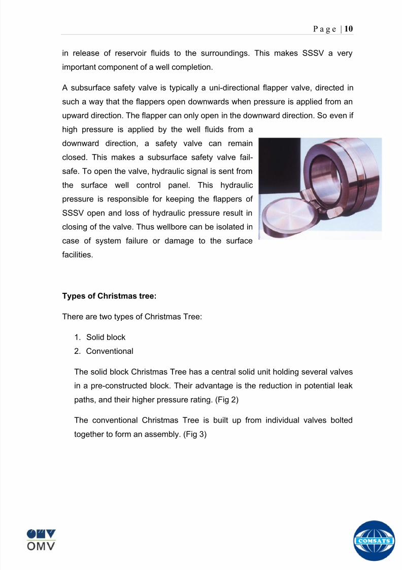
8102019 Gas sweetening Plant
httpslidepdfcomreaderfullgas-sweetening-plant 1462
P a g e | 10
in release of reservoir fluids to the surroundings This makes SSSV a very
important component of a well completion
A subsurface safety valve is typically a uni-directional flapper valve directed in
such a way that the flappers open downwards when pressure is applied from an
upward direction The flapper can only open in the downward direction So even if
high pressure is applied by the well fluids from a
downward direction a safety valve can remain
closed This makes a subsurface safety valve fail-
safe To open the valve hydraulic signal is sent from
the surface well control panel This hydraulic
pressure is responsible for keeping the flappers of
SSSV open and loss of hydraulic pressure result in
closing of the valve Thus wellbore can be isolated in
case of system failure or damage to the surface
facilities
Types of Christmas tree
There are two types of Christmas Tree
1 Solid block
2 Conventional
The solid block Christmas Tree has a central solid unit holding several valves
in a pre-constructed block Their advantage is the reduction in potential leak
paths and their higher pressure rating (Fig 2)
The conventional Christmas Tree is built up from individual valves bolted
together to form an assembly (Fig 3)
8102019 Gas sweetening Plant
httpslidepdfcomreaderfullgas-sweetening-plant 1562
P a g e | 11
Figure 2
Figure 3
8102019 Gas sweetening Plant
httpslidepdfcomreaderfullgas-sweetening-plant 1662
P a g e | 12
Wellhead Control Panel
Wellhead control panel is key equipment in oil amp gas industry to protect oilfield
facilities and environment from emergency incidents such as wellhead fire which
is one of main control systems to ensure oilfield oil production and transportation
to be safely operation according to international standards and national
regulation Wellhead control panel is composed of hydraulic power unit tubing amp
fitting and instrument valve and electrical control devices Hydraulic power unit
supply hydraulic resource to open and close safety valves including master
valves wing valves and SCSSSV
Its performs
Local OnOff SSV
Remote control SSV through RTU( remote terminal unit)
High-Low pressure sense shut-down automatically
Fusible Plug Anti-fire Shut-down automatically
Function of showing system pressure
Relief Valve shall be installed on each hydraulic circuit to prevent high
pressure
Function of showing hydraulic level and level switch for alarm
Function of defending pressure impact of system
Function of system pressure monitoring (by pressure transmitter of control
panel)
Function of remote emergency shut-down (by magnetic valve of control
panel)
Function of OnOff SSV monitoring (by pressure switch of control loop of
control panel)
8102019 Gas sweetening Plant
httpslidepdfcomreaderfullgas-sweetening-plant 1762
P a g e | 13
Chemical Injection
Chemical injection systems are commonly used in production facilities to prevent
or eliminate a wide range of problems that might negatively affect the production
flow It is done for flow assurance protection of process equipment such as
pipelines or to optimize processes in production facilities
Typical flow assurance chemicals are
Wax inhibitors
Pour point depressants
Asphaltene inhibitors
Corrosion inhibitors
A corrosion inhibitor is a chemical compound that is added to liquid or gas to
decreases the corrosion rate of a material typically a metal or an alloy The
effectiveness of a corrosion inhibitor depends on fluid composition quantity of
water and flow regime Its common mechanism involves formation of a coating
8102019 Gas sweetening Plant
httpslidepdfcomreaderfullgas-sweetening-plant 1862
P a g e | 14
which prevents access of the corrosive substance to the metal The corrosive
agents are generally oxygen hydrogen sulfide and carbon dioxide
At our production site the major risk is corrosion of piping and equipment The
maximum allowable corrosion rate is approximately 02 mm per year and
corrosion rate without inhibitor could be approximately 11 mm per year so the
corrosion protection program is designed to achieve a target corrosion rate of
less than 01 mm per year which is achieved by an inhibitor system efficiency of
99 Inhibitor is injected into the well stream flow through an atomizing nozzle
located downstream of the respective wellhead coolers at the duplexcarbon steel
interface In normal operation as per NALCO standards chemical (brand name
EC1144B) at rate of frac12 Liter per MMSCFD of gas is being injected into the flow
line of miano15 flow lines made of carbon steel Moreover the composition can
vary depending upon the composition of well fluids and material of pipeline This
method of injection ensures even distribution of the chemical on the interior
surface of the pipeline The individual well sites are equipped with Chemical
Injection Packages comprising of a stainless steel storage tank and two
pneumatic motor driven pumps in parallel Instrument gas is used to drive the
pumps Normally one pump is running with the other standby
Water Conning
Water coning is a term used to describe the mechanism underlying the upward
movement of water into the perforations of a producing well Coning can seriously
impact the well productivity and influence the degree of depletion and the overall
recovery efficiency of the reservoir The specific problems of water coning are
listed below
Costly added water handling
Gas production from the original or secondary gas cap reduces pressure
Reduced efficiency of the depletion mechanism
The water is often corrosive and its disposal costly
The affected well may be abandoned early
Loss of the total field overall recovery
8102019 Gas sweetening Plant
httpslidepdfcomreaderfullgas-sweetening-plant 1962
P a g e | 15
Therefore conning has an important influence on operations recovery and
economics The phenomena is shown in picture below
Corrosion
Corrosion is referred as chemical deterioration of a metal Commonly this
means loss of electrons of metals reacting with water and oxygen
Weakening of iron due to oxidation of the iron atoms is a well-known
example of electrochemical corrosion This is commonly known as
rust Most structural alloys corrode merely from exposure to moisture
in the air but the process can be strongly affected by exposure to
certain substances Corrosion can be concentrated locally to form a pit
or crack or it can extend across a wide area to produce general
deterioration (uniform corrosion)
The following reaction takes place at the active sites
2Fe =gt 2Fe++ + 4e-
The free electrons travel through the metal path to the less active sites where
the following reaction takes place
O2 + 4e- + 2H20 =gt 4 OH-
8102019 Gas sweetening Plant
httpslidepdfcomreaderfullgas-sweetening-plant 2062
P a g e | 16
Recombination of these ions at the active surface produce the following
reaction which yields the iron-corrosion product ferrous hydroxide
2Fe + O2 + 2H2O =gt 2Fe (OH) 2
CORROSION PROTECTION SYSTEM
Coatings and painting
Painting and the application of enamel bitumen and PVC
coating are the most common anti-corrosion treatments They
work by providing a barrier of corrosion-resistant material
between the damaging environment and the structural material
Corrosion Inhibitors
Corrosion inhibitor is injected into the flow lines as mentioned in
detail on page 8
Cathodic Protection
Cathodic Protection (CP) is a technique used to control the corrosion of a
metal surface by making it the cathode of an electrochemical cell It
converts all of the anodic (active) sites on the metal surface to cathodic
(passive) sites by supplying electrical current (or free electrons) from an
alternate source It is accomplished in two ways
a) A simple method of protection connects protected metal to a more easily
corroded sacrificial metal to act as the anode The sacrificial metal then
corrodes instead of the protected metal The process is similar to a simple
DC cell in which the more active metal becomes the anode and corrodes
whereas the less active metal becomes the cathode and is protected
b) For larger structures galvanic anodes cannot economically deliver enough
current to provide protection Therefore impressed current cathodic
protection (ICCP) systems are used These consist of anodes connected
to a DC power source In remote areas power sources such as solar
panels may be used The output DC negative terminal is connected to the
8102019 Gas sweetening Plant
httpslidepdfcomreaderfullgas-sweetening-plant 2162
8102019 Gas sweetening Plant
httpslidepdfcomreaderfullgas-sweetening-plant 2262
P a g e | 18
frequently to limit liquid holdup and minimize the slug volumes of liquid which can
be generated by the system
Coating
Pigs may be used to apply internal pipe coatings such as epoxy coating
materials in operating pipelines Pigs may also be used with corrosion inhibitors
to distribute and coat the entire internal wetted perimeter
Inspection
Pigs are being used more frequently as inspection tools Gauging or sizing pigs
are typically run following the completion of new construction or line repair to
determine if there are any internal obstacles bends or buckles in the pipe Pigs
can also be equipped with cameras to allow viewing of the pipe internals
Electronic intelligent or smart ldquopigsrdquo that use magnetic and ultrasonic systems
have been developed and refined that locate and measure internal and external
corrosion pitting dents buckles and any other anomalies in the pipe wall
Intelligent pigs
The accuracy of location and measurement of anomalies by the intelligent pigs
has continued to improve Initially the electronics and power systems were so
large that intelligent pigs could be used only in lines 30 in and greater in size
The continued sophistication and miniaturization of the electronic systems used
in the intelligent pigs has allowed the development of smaller pigs that can be
used in small-diameter pipelines Newly enacted DOT pipeline-integrity
regulations and rules acknowledge the effectiveness of the intelligent pigs and
incorporate their use in the pipeline-integrity testing process
Compressors
A gas compressor is a mechanical device that increases the pressure of a gas by
reducing its volume Gas pressure is increased by forcing gas molecules together
to reduce gas volume When volume is reduced gas pressure increases
All gases have large spaces among their molecules These spaces could be
enhanced further and decreased by doing some work Work done which is used
8102019 Gas sweetening Plant
httpslidepdfcomreaderfullgas-sweetening-plant 2362
P a g e | 19
for the enhancement of these spaces is called expansion and work done to
minimize these spaces is called compression All gases while expansion
produces cooling effect and while compression of gases raises there
temperature Compression is a term used to force gases to occupy smaller
volumes by increasing their pressure Volume of gases is interlinked with
temperature and pressure of the gas which is cleared by 2 laws govern gas
compressions
Boyles Law
Charles Law
The main types of compressor are listed below
Front End Compressor
The plant currently processes gas from a number of wells The flow and pressure
from some of these wells (currently K-10 K-11 amp K-12) has declined and they
cannot be fed directly into the Central Processing Facility To recover the
maximum gas reserves from these wells a Front End Compressor is employed
The compressor is a two stage double acting gas engine driven reciprocating
(PT) compressor Double acting means that gas is compressed on each end of
the piston It normal operates with a speed range of 600 to 900 RPM and isequipped with four compressor cylinders two for each stage Each cylinder is
8102019 Gas sweetening Plant
httpslidepdfcomreaderfullgas-sweetening-plant 2462
P a g e | 20
also equipped with a variable volume head end pocket
In case of compressor emergency shutdown the production chokes and the
Upper Master Valves on the on line wells will close and operator will be notified in
central control room Sweet gas from gas distribution network is used to operate the
gas engine driver of the compressor package The detailed scheme of working is
shown in figure (page 22 )
PT Reciprocating Compressor
The mechanical cycle of piston tube reciprocating compressor comprises four
strokes the expansion stroke the intake stroke the compression stroke and the
discharge stroke
Expansion Stroke
As the piston moves back on the expansion stroke the chamber volume
increases and the pressure drop As the pressure drops the discharge valve
closes since there is greater pressure in the discharge line than in the chamber
Intake Stroke
As the piston moves back during the intake stroke the pressure decreases until it
is less than the pressure in the inlet line This higher intake pressure opens the
inlet valve and gas rushes into the cylinder equalizing the pressure there with
the intake pressure The compression chamber is now at or near the intake
pressure
Compression Stroke
The piston now starts the compression stroke by moving forward decreasing the
chamber volume and increasing the pressure The increased pressure is now
higher than the intake pressure causing the intake valve to close
Discharge Stroke
The piston continues to move to the left during the discharge stroke This creates
an increase in chamber pressure until it is greater than the discharge pressure
When this happens the Discharge valve opens and the compressed air from the
8102019 Gas sweetening Plant
httpslidepdfcomreaderfullgas-sweetening-plant 2562
P a g e | 21
cylinder goes into the discharge line The compression cycle is then repeated
from the stage
Compressor Capacity
The capacity of the compressor depends upon cylinder displacement That
displacement is simply the volume that the piston displaces (moves) as it travels
from one end of the cylinder to the other Capacity and displacement is equal to
the cross-sectional area of the cylinder times the length of the stroke
Lubrication and Cooling
Lubricating oil is circulated through the system by a gear pump which is chain
driven from the engine crank shaft The oil pump is mounted on the engine front
housing
The pump operates between 30 - 40 psig
8102019 Gas sweetening Plant
httpslidepdfcomreaderfullgas-sweetening-plant 2662
P a g e | 22
A circulating pump deliver cooling water to the water jackets in the cylinder block
flowing around the cylinder liners and is directed into the cylinder heads Each
cylinder head has water cooled exhaust elbows which outlet the water into the
water cooled exhausts From the end of engine the water flows to compressor
1st and 2nd stage cylinders and compressor lube oil cooler (LOwater heat
exchanger) The water from the compressor cylinder and lube oil cooler returns
to engine water cooled exhaust
Figure Flow diagram of Front End Compressor
8102019 Gas sweetening Plant
httpslidepdfcomreaderfullgas-sweetening-plant 2762
P a g e | 23
Centrifugal Compressor
Centrifugal compressors are machines in which velocity and pressure given to air
or gas in a radial direction by one or more impellers diffuser combination In a
centrifugal compressor the mechanical energy is increased by centrifugal action
The gas enters the suction eye of a high speed rotary element called the impeller
which carries radial vanes integrally cast in it As the impeller rotates the blades
of the impeller force the gas outward from the center the impeller to the outer rim
of impeller the increase in velocity of the gas creates a flow pressure area at the
eye of the impeller The gas at the outer rim of the impeller is forced in to a
passage way called a diffuser where the velocity decreases in the pressure of the
gas
Inlet
The inlet to a centrifugal compressor is typically a simple pipe It may include
features such as a valve and both pressure and temperature instrumentation
Centrifugal impeller
The key component that makes a compressor centrifugal is the centrifugal
impeller shown above It is the impellers rotating set of vanes (or blades) that
gradually raises the energy of the working gas This is identical to an axial
compressor with the exception that the gases can reach higher velocities and
energy levels through the impellers increasing radius
8102019 Gas sweetening Plant
httpslidepdfcomreaderfullgas-sweetening-plant 2862
P a g e | 24
Diffuser
The next key component to the simple centrifugal compressor is the diffuser
Downstream of the impeller in the flow path it is the diffusers responsibility to
convert the kinetic energy (high velocity) of the gas into pressure by gradually
slowing (diffusing) the gas velocity
SEPERATORS
A well-stream is a mixture of gases hydrocarbon liquids water solids and
contaminants Due to variations in pressure and temperature gases evolve from
the liquids water vapor condenses and some of the well-stream changes to liquid
and free gas The separation of well-stream fluids takes place in a separator This
pressure vessel is manufactured in three forms
1 horizontal
2 vertical
3 spherical
To help separation the vessel is normally designed with a series of internal
fittings These fittings are built into the separator to ensure total phase separation
of the well-stream
In gas plants separators are given alternative names due to the function they
perform in the process system A scrubber does a similar job to a knockout drum
However the scrubber usually separates a stream containing high gas-to-liquid
ratios The knockout drum is used where a high degree of liquids are entrained in
the gas
Fluid flow from a well can include gas condensable liquid vapors water water
vapor crude oil and solids As well-stream fluids reach ground level where
pressure is lower than in the reservoir the capacity of the liquid to hold gas in
solution decreases and gas separates out of the oil
Separation depends upon the effect of gravity to separate liquids For adequate
separation one fluid must be lighter than the other fluid For example distillates
8102019 Gas sweetening Plant
httpslidepdfcomreaderfullgas-sweetening-plant 2962
P a g e | 25
(gasoline kerosene etc) and crude oil will not separate in a vessel because they
tend to dissolve in each other Because a separator basically depends upon
gravity to separate the fluids the ease with which separation takes place
depends upon the difference in density of the fluids
Droplets of liquid will separate from gas provided
a) The gas remains in the separator long enough
b) The gas flow remains constant to provoke separation
The difference in density between a gas and liquid will therefore determine the
maximum flow rate of liquid in the vessel
Figure Two phase horizontal separator
Gas bubbles in the liquid will break out in some oil field applications in 30 to 60
seconds Consequently the separator is designed so that the liquid remains in
the vessel for 30 to 60 seconds The length of time that a liquid remains in the
vessel is called its residence time Residence time differs widely from field to field
depending upon viscosity and API Gravity
Another important factor which must be considered is temperature Generally a
decrease in operating temperature will increase the liquid recovery in a separator
8102019 Gas sweetening Plant
httpslidepdfcomreaderfullgas-sweetening-plant 3062
P a g e | 26
as the gas condenses By reducing the pressure on the fluid flash separation
occurs resulting in a flow through the separator which is controlled by external
instrumentation
COALESCENCE
Another important principle in fluid separation is that of coalescence This means
the coming together of liquid droplets created by the force of gravity
A common example of coalescing occurs when drops of water form on the
windshield of a car as it is driven in fog As the tiny drops or water which make up
the fog strike the windshield they combine and eventually form a drop large
enough to run down the glass
Several of the internal devices of a separator such as deflector plates
straightening vanes and even the vessel walls are forms of coalescers In each
vessel drops of liquid adhere to the surface of the device and combine with other
8102019 Gas sweetening Plant
httpslidepdfcomreaderfullgas-sweetening-plant 3162
P a g e | 27
drops until the drop is large enough to fall out The effectiveness of separation
will also depend upon the total amount of coalescing surface area that is present
There are many different types of separators used in the Oil amp Gas industry
Consequently separators are manufactured with one two or several internal
fittings depending on their use and quick removal of these fluids from the vessel
DEFLECTOR PLATES
These are fitted in front of the inlet to the separator and can be net or
dish-shaped Their purpose is to absorb the impact of the incoming fluids and to
encourage the separation of gas and liquids They also slow the flow rate of the
liquids through the vessel
WEIRS
A weir is a metal wall which is fitted across the inside of the vessel normally to a
height of 50 of the overall height of the separator Its purpose is to assist the
process of three phase separation The inlet fluids (oil plus water) are given time
to separate in the liquid accumulation section The water level (interface) is
normally controlled at 50 of the height of the weir Oil floating on the wateroverflows the weir and accumulates in the small oil compartment where it is
drawn off under level control
CENTRIFUGAL DEVICES
These are used in both vertical and horizontal separators for gas-liquid
separation The device imparts a swirling motion to the fluids entering the vessel
Centrifugal force causes the heavier liquids to travel outwards towards the walls
of the vessel and the lighter gases to flow up the centre Centrifugal devices are
also known as cyclones
VORTEX BREAKERS
When liquid flows through a drain outlet a vortex (whirlpool) will form This can
be seen when we pull the plug from a sink or bath tub The same would happen
as water and oil flow from the separator This condition a vortex could allow gas
to flow down the centre of the whirlpool and enter the liquid phase causing
8102019 Gas sweetening Plant
httpslidepdfcomreaderfullgas-sweetening-plant 3262
P a g e | 28
pressurizing of tanks etc To stop this happening vortex breakers are fitted to all
liquid outlets Although they come in a number of different designs vortex
breakers all serve the same purpose - to prevent a whirlpool from forming
MIST OR DEMISTER PADS
The gas which is released from the fluids in the separator still contains droplets of
oil and water which coalesce and fall when the drops get large enough The
demister pad assists in this process Made from knitted wire and contained within
a sturdy frame it causes the gas to continually change its direction of flow
Because gas changes direction far easier than liquid the gas will flow around
each strand of wire whilst the liquid entrained in the gas stream will continue and
stick to the wire
COALESCING PLATES
There are several different forms of coalescing devices the most common of
which are coalescing plates These plates are mounted in the flow stream of the
fluids and assist in breaking down oil-water emulsions The fluid is forced to
follow a path that constantly changes direction This causes the water droplets to
gather together or coalesce and fall to the bottom of the separator The same
principle is used to separate gas and oil mixtures when the oil droplets are
induced to coalesce Simply stated every surface within the separator including
the separator walls assists with the coalescing process
STRAIGHTENlNG VANES
These are often fitted to horizontal separators to remove turbulence in the gas
stream after initial separation at the inlet deflector
FLOAT SHEILD
Internal floats are used as level controllers Any agitation of the liquid surface or
the effect of coalesced liquids falling on the float may cause control problems
Therefore a float shield is fitted to enclose the float creating an area of still liquid
8102019 Gas sweetening Plant
httpslidepdfcomreaderfullgas-sweetening-plant 3362
P a g e | 29
MEMBRANES
The gas contains 12 carbon dioxide and 22 ppm of hydrogen sulphide at 115oF
and 1100 psig This needs to be removed before the gas can be exported The
majority of carbon dioxide hydrogen sulphide and water is removed by means of
membranes
Membranes are thin semipermeable barriers that selectively separate some
compounds from others Currently the only commercially workable membranes
used for CO2 removal are polymer based for example cellulose acetate
polyimides polyamides polysulfone polycarbonates and polyetherimide The
membrane does not operate as a filter where small molecules are separated
from larger ones through a medium with pores rather it separates based on how
well different compounds dissolve into the membrane and diffuse through it The
membranes are manufactured in flat sheets consisting of an extremely thin
nonporous layer mounted on a much-thicker and highly porous layer of the same
material providing mechanical strength The flat sheets are combined into a
spiral-wound element (Figure below) Feed gas enters along the side of the
membrane and passes through the feed spacers As the gas travels between
membrane sheets CO2 H2S and H2O permeate through the membrane and are
collected in the permeate tube The driving force for transport is the high-feed
pressure and low-permeate pressures The gas on the feed side that does not
permeate leaves through the side of the element opposite the feed position Once
the membranes have been manufactured into elements six to 12 elements are
joined together and inserted into a tube Multiple tubes are mounted on skids in a
horizontal orientation
8102019 Gas sweetening Plant
httpslidepdfcomreaderfullgas-sweetening-plant 3462
P a g e | 30
Figure Membrane general Working
In high H2S applications most polymers have been shown to have very little
resistance to H2S plasticization (ldquosofteningrdquo of the membrane) and as a
consequence can only be used at very low H2S partial pressure limits Cellulose
acetate membranes in contrast have been shown to be applicable at extreme
H2S partial pressure conditions It is these membranes that have been utilized in
the testing to determine the limits of membrane performance in high H 2S
applications
The primary membranes used in Kadanwari facility are Cellulose acetate
Cellulose acetic acid and acetic anhydride are mixed together and reacted to
form cellulose acetate polymers This process is aided by the addition of a small
amount of sulfuric acid which is subsequently neutralized during processing
However the membranes are bought from UOP (vendor) and installed for use
8102019 Gas sweetening Plant
httpslidepdfcomreaderfullgas-sweetening-plant 3562
P a g e | 31
How membrane work
The basic principle of separation is selectivity of certain components of a mixture
for the membrane For example the cellulose acetate membrane has very high
selectivity for CO2 and H2S as compared to CH4 Therefore such type of
membrane can be used in gas sweetening process
The selectivity is directly related to the Permeability of gas which accounts that
which gas can pass across the membrane more easily In simple words
membranes being polymer materials are made of long chains of molecules The
different structure of polymer materials only allow selective molecules to pass
through them depending upon chemical and physical compatibility Thus
permeability depends upon choice of polymer
The permeability is determined by permeability coefficient (P) and is product of
solubility (S) and diffusivity (D)
P = S D
Solubility
The solubility is mainly determined by ease of condensation Heavy molecules
are more readily condensed Therefore higher molecular weighted molecules will
more easily condensed and therefore have greater solubility
Molecule Molecular weight
CH4 16
H2S 34
CO2 44
8102019 Gas sweetening Plant
httpslidepdfcomreaderfullgas-sweetening-plant 3662
P a g e | 32
Diffusivity
Diffusivity is ease of molecule to penetrate into some material It depends on size
of gas molecule Here size of molecule is not to be confused by molecular weight
it is the size of the structure Eg the size of O2 molecule is smaller than N2
Molecule Molecular Diameter (Ao)
CO2 33
H2S 36
Ch4 40
For cellulose acetate
DCO2DCH4 S CO2S CH4 P CO2P CH4
45 73 308
Chemical degradation
Cellulose acetate polymer is chemically degraded by a process called hydrolysis
which means breaking apart by the addition of water This is a chemical reaction
in which water is added to the cellulose acetate polymer causing the release of
acetic acid molecules This process proceeds stepwise until all the acetate
groups are released resulting in the reformation of cellulose Moreover alcohols
aromatic hydrocarbons or solvents with chlorine nitro benzene or similar
aromatic solvents will harm the membrane It will expand and lose plastification in
contact with them
Effect of Temperature
The permeation rates of all gases increases with increasing temperature
however membrane selectivity for CO2 over hydrocarbon decreases at higher
8102019 Gas sweetening Plant
httpslidepdfcomreaderfullgas-sweetening-plant 3762
P a g e | 33
temperature Consequently CO2 removal will improve as operating temperature
increases but hydro carbon recovery will decrease
Primary Membrane
The primary membranes comprise of two trains Each train consists of two
sections AB and CD each section consists of a 30 tube membrane skid (A and
C) followed by a 25 tube skid (B and D) The conditioned gas (after pre-
treatment) enters the primary membrane via the particulate filter adjacent to the
skid The gas is fed to the membranes through a common inlet manifold which
supplies primary membranes skids A and C A pressure control loop located
upstream of the manual inlet isolation valve is provided to maintain a constant
supply pressure to the membrane skid and to allow for preheating at the inlet
prior to skid start-up This pressure control loop can also be used during start-up
to control the pressurization of the pretreatment skid and associated pipes to the
primary membranes
The gas passes through membrane skid A the residual gas exiting the membrane
skid is sent to skid B and the permeate to common permeate discharge header An
identical arrangement is provide on the inlet to skid C as provided on skid A Theresidual gas from skid B combines with the residual gas from skid D in a common
discharge header and is then sent to the H2S polishing towers via the feed coolers
on the pre-treatment skid The permeate from skid B is sent to the common
permeate discharge header The permeate discharge header sends the gas to
either the recycle compressor or the vent header via a pressure control loop
Overpressure protection for the membranes is provided by a pressure safety valve
on the supply header to the membrane banks
8102019 Gas sweetening Plant
httpslidepdfcomreaderfullgas-sweetening-plant 3862
P a g e | 34
Secondary (Recycle) Membrane
The recycle membranes comprise of a single train with two skids each with four
banks of membrane tubes The conditioned gas from the discharge of the recycle
pre-treatment skid is routed to the first recycle membrane skid The gas passes
through the membranes the residual gas is fed to primary membrane (skid A) inlet
via feed gas cooler and permeate to the common permeate discharge header An
identical arrangement is provide on the inlet to skid B Permeate from the recycle
membrane skids A and B is routed to the vent header Some portion of permeate is
heated and sent for regeneration in Mem-Guard units Nitrogen purge can be
connected downstream of the inlet isolation valve on each skid to enable the
membrane tubes to be purged and left pressurized during prolonged shutdown
8102019 Gas sweetening Plant
httpslidepdfcomreaderfullgas-sweetening-plant 3962
P a g e | 35
Figure Flow Diagram of Recycle membrane unit
8102019 Gas sweetening Plant
httpslidepdfcomreaderfullgas-sweetening-plant 4062
P a g e | 36
ADVANTAGES OF MEMBRANE SYSTEMS
Membrane systems have major advantages over more-traditional methods of
acid gas removal
Lower capital cost Membrane systems are skid mounted and so the
scope cost and time taken for site preparation are minimal Installation
costs are significantly lower than alternative technologies especially for
remote areas Furthermore no additional facilities for solvent storage and
water treatment needed by other processes are required
Lower operating costs The only major operating cost for single-stage
membrane systems is membrane replacement This cost is significantly
lower than the solvent replacement and energy costs associated with
traditional technologies The improvements in membrane and
pretreatment design allow a longer useful membrane life which further
reduces operating costs The energy costs of multistage systems with
large recycle compressors are usually comparable to those for traditionaltechnologies
Deferred capital investment Often contracted sales-gas flow rates
increase over time as more wells are brought on-line With traditional
technologies the system design needs to take this later production into
account immediately and so the majority of the equipment is installed
before it is even needed The modular nature of membrane systems
means that only the membranes that are needed at start-up need be
installed The rest can be added either into existing tubes or in new skids
only when they are required
Operational simplicity and high reliability Because single-stage
membrane systems have no moving parts they have almost no
8102019 Gas sweetening Plant
httpslidepdfcomreaderfullgas-sweetening-plant 4162
P a g e | 37
unscheduled downtime and are extremely simple to operate They can
operate unattended for long periods of time The addition of a recycle
compressor adds some complexity to the system but still much less than
with a solvent- or adsorbent-based technology Multistage systems can be
operated at full capacity as single-stage systems when the recycle
compressor is down
Good weight and space efficiency Skid construction can be optimized
to the space available This space efficiency is especially important for
offshore environments where deck area is at a premium and is the
reason why so many new offshore developments have chosen to use
membranes for acid gas removal Figure 6 illustrates the space efficiency
of membrane systems The membrane unit in the lower left corner
replaced all the amine and glycol plant equipment shown in the rest of the
picture
Adaptability Because membrane area is dictated by the percentage of
acid gas removal rather than absolute acid gas removal small variations
in feed acid gas content hardly change the sales-gas acid gas
specification For example a system designed for 10 down to 3 acid
gas removal produces a 35 product from a 12 feed gas and a 5
product from a 15 feed gas
Design efficiency The membrane and pretreatment systems integrate a
number of operations such as dehydration CO2 and H2S removal dew-
point control and mercury removal Traditional acid gas removal
technologies require all of these operations as separate processes and
may also require additional dehydration because some technologies
saturate the product stream with water
8102019 Gas sweetening Plant
httpslidepdfcomreaderfullgas-sweetening-plant 4262
P a g e | 38
Power generation The permeate gas from membrane systems can be
used to provide fuel gas for power generation either for a recycle
compressor or other equipment
Ideal for debottlenecking Because expanding solvent- or adsorbent-
based acid gas removal plants without adding additional trains is difficult
an ideal solution is to use membranes for bulk acid gas removal and leave
the existing plant for final cleanup An additional advantage is that the
permeate gas from the membrane system can often be used as fuel for
the existing plant thus avoiding significant increase in hydrocarbon
losses
Environmentally friendly Membrane systems do not involve the
periodic removal and handling of spent solvents or adsorbents Permeate
gases can be flared used as fuel or re-injected into the well Items thatdo need disposal such as spent membrane elements can be incinerated
Ideal for remote locations Many of the factors mentioned above make
membrane systems a highly desirable technology for remote locations
where spare parts are rare and labor unskilled Furthermore solvents
storage and trucking water supply power generation or extensive
infrastructure are not required
Re-injection optimizations Since the permeate stream from the
membrane system can be operated at elevated pressures it is possible to
further pressurize by re-injection compression train
8102019 Gas sweetening Plant
httpslidepdfcomreaderfullgas-sweetening-plant 4362
P a g e | 39
Sorption
Sorption is a physical and chemical process by which one substance becomes
attached to another
It is of two main types
1 Absorption
2 Adsorption
Absorption
Absorption is a physical or chemical phenomenon or process in which atoms
molecules or ions enter some bulk phase ndash gas liquid or solid material This is a
different process from adsorption since molecules undergoing absorption are
taken up by the volume not by the surface (as in the case for adsorption)
Absorption process may be chemical (reactive) or physical (non-reactive)
Physical absorption
Physical absorption or non-reactive absorption is made between two phases ofmatter a liquid absorbs a gas or a solid absorbs a liquid
When a liquid solvent absorbs a gas mixture or part of it a mass of gas moves
into the liquid For example water may absorb oxygen from the air This mass
transfer takes place at the interface between the liquid and the gas at a rate
depending on both the gas and the liquid This type of absorption depends on the
solubility of gases the pressure and the temperature The rate and amount of
absorption also depend on the surface area of the interface and its duration in
time
When a solid absorbs a liquid mixture or part of it a mass of liquid moves into the
solid For example a clay pot used to store water may absorb some of the water
This mass transfer takes place at the interface between the solid and the liquid
at a rate depending on both the solid and the liquid
8102019 Gas sweetening Plant
httpslidepdfcomreaderfullgas-sweetening-plant 4462
P a g e | 40
Chemical absorption
Chemical absorption or reactive absorption is a chemical reaction between the
absorbed and the absorbing substances Sometimes it combines with physical
absorption This type of absorption depends upon the stoichiometry of the
reaction and the concentration of its reactants
Adsorption
Adsorption is the adhesion of atoms ions or molecules from a gas liquid or
dissolved solid to a surface This process creates a film of the adsorbate on the
surface of the adsorbent The binding to the surface is usually weak and
reversible Compounds with color and those that have taste or odor tend to bind
strongly Compounds that vibrate at frequencies in the visible spectrum are very
often are strongly adsorbed on activated carbon
The most common industrial adsorbents are activated carbon silica gel and
alumina because they present enormous surface areas per unit weight
Depending on the nature of attractive forces existing between the adsorbate and
adsorbent adsorption can be classified as
i) Physical adsorption
ii) Chemical adsorption
i) Physical adsorption (Physisorption)
In physical adsorption the forces of attraction between the molecules of the
adsorbate and the adsorbent are of the weak van der Waals type Since the
forces of attraction are weak the process of physisorption can be easily reversed
by heating or decreasing the pressure of the adsorbate (as in the case of gases)
8102019 Gas sweetening Plant
httpslidepdfcomreaderfullgas-sweetening-plant 4562
P a g e | 41
ii) Chemical adsorption (Chemisorption)
In chemisorption the forces of attraction between the adsorbate and the
adsorbent are very strong the molecules of adsorbate form chemical bonds with
the molecules of the adsorbent present in the surface
Adsorption is generally accompanied by release of energy that is most
adsorption processes are exothermic in nature Adsorption is a spontaneous
process therefore its free energy change is negative (∆Glt0) However the
entropy change associated with adsorption is generally negative because the
adsorbate molecules lose their translation freedom when they get attached to the
surface of the adsorbent Therefore in order for ∆G to be negative the enthalpy
change (∆H) must be sufficiently negative such that (∆G=∆H-T∆S) lt 0 This
explanation accounts for exothermic adsorption processes In cases where
endothermic adsorption occurs the entropy change ∆S is sufficiently positive
such that ∆G remains negative
Pre treatment
The main function of pretreatment skid is to provide membrane inlet specification
gas as mentioned by the vendor UOP It removes the contaminants that would
poison the membranes like dust solids (adsorbent particles) lube oil heavy
hydrocarbons etc It consists of
Feed Cooler
Feed Gas Scrubber
Filter Coalescer
Feed Gas Heater
Activated Carbon Guard Filter
Particle Filter
8102019 Gas sweetening Plant
httpslidepdfcomreaderfullgas-sweetening-plant 4662
8102019 Gas sweetening Plant
httpslidepdfcomreaderfullgas-sweetening-plant 4762
P a g e | 43
The regeneration is carried out by heated permeate gas from the recycle
membranes at 450oF The vessel is depressurized to 20 psi and heated gas is
introduced from top The gas carries out the adsorbed contaminants and leaves
the vessel from bottom cleaning the adsorbent This contaminated gas is burnt in
the flare
UOP the vendor of Memguard unit has never disclosed that what substance
MG3 and MG5 exactly are But as mentioned by vendor that both care class of
aluminosilicates Therefore MG3 can be potassium aluminosilicate and MG5 can
be Calcium aluminosilicate These are molecular sieves adsorbents Molecular
sieves are a microporous material which can selectively adsorb gases andliquids They are synthetic zeolites (crystalline metal aluminosilicates) which
upon dehydration can efficiently and selectively remove water or other
solvents The selectivity of a molecular sieve is determined by its pore size
molecules with a critical diameter which is less than the pore size will be
efficiently adsorbed while larger molecules will be excluded
8102019 Gas sweetening Plant
httpslidepdfcomreaderfullgas-sweetening-plant 4862
P a g e | 44
3A Molecular Sieve Adsorbent
The 3A molecular sieve adsorbent has a 3 angstrom (3A) pore size which means
that any molecule that is larger than the 3 angstrom pores will not be adsorbed
The 3A molecular sieve is the potassium type of A crystalline structure and is a
form of alkali Aluminosilicate For a 3A molecular sieve the sequence rate that
adsorption occurs is He Ne N and H2O
Due to the crystalline structure molecular sieves that have a 3 angstrom pore
size have a very high rate of adsorption and properties that promote a longer life
for products treated by the sieve The most common use for the 3A molecular
sieve is to remove water and moisture from materials that are in gas and liquid
form
5A Molecular Sieve Adsorbent
These are molecular sieve adsorbents with a pore size of 5 angstrom (5A) 5A
molecular sieves are unable to adsorb any molecules or impurities that are
smaller than 5A It is calcium form of type A crystalline structure and is form of analkali-aluminosilicate that is most commonly used to separate isomerous alkanes
from normal alkanes and to co-adsorb moisture and water along with carbon
dioxide from gases In additional 5A molecular sieves are used for gaseous
pressure swing adsorption (PSA)mdashthat is to separate particular gases from other
gases
Adsorption of nC4H10
Adsorption of nC4H10
Adsorption of C3H8 to C22H46
Adsorption of Freon-12 (dichlorodifluoromethane)
Natural gas drying
Normal- and iso-paraffin separation
Separation of aromatic
8102019 Gas sweetening Plant
httpslidepdfcomreaderfullgas-sweetening-plant 4962
P a g e | 45
Inlet Composition of Memguard vessel
COMPSOSITION MOLE
CARBON DIOXIDE 1096
MEHTANE 8593
ETHANE 173
PROPANE 023
I-BUTANE 008
N BUTANE 004
PENTANES 004
HEXANE + 000
NITROGEN 076
WATER 007
Outlet Composition of Memguard vessel
COMPSOSITION MOLE
CARBON DIOXIDE 1098
MEHTANE 8608
ETHANE 173
PROPANE 023
I-BUTANE 008N BUTANE 004
PENTANES 004
HEXANE + 000
NITROGENT 076
WATER 000
H2S polisher
The H2S polishing unit has been designed to treat 187 MMscfday of natural gas
containing up to 11 CO2 and 21 ppm H2S where the level of the CO2 and H2S
is reduced using a MemGuard Membrane separation unit The unit is situated
down-stream of the membrane unit and will further reduce the level of H2S in the
processed gas to a sales gas specification of 38 ppm
8102019 Gas sweetening Plant
httpslidepdfcomreaderfullgas-sweetening-plant 5062
P a g e | 46
This process uses three non-regenerable fixed bed absorber vessels using a low
temperature high activity absorbent The absorbent is a mixture of activated
metal oxides (mainly zinc oxide) The three towers can are generally operated in
parallel arrangement but on demand can be used in series (any of alternate
arrangements of A B C vessels) as shown in figure
The higher sales gas flow rate increased the catalyst consumption and
replacement frequency
ZnO + H2S =gt ZnS + H20
Routine samples are taken from the beds to provide a check on each bed
performance and to follow the saturation profile during the absorbent life After
the adsorbent has been fully utilized the adsorption vessels are recharged with
new adsorbent discarding the utilized one in a safe manner
109oF
1215 psig
Before H2S Polishing After H2S Polishing
8102019 Gas sweetening Plant
httpslidepdfcomreaderfullgas-sweetening-plant 5162
P a g e | 47
Figure
H2S Tower
Inlet pipe
4 Drums of 19mm
ceramic Balls
6 Micron mesh
5 Drums of 50mmceramic
1 Drums of19mm ceramic
01 Drums of6mm ceramic
112 drums of
Catalist ZnO
8102019 Gas sweetening Plant
httpslidepdfcomreaderfullgas-sweetening-plant 5262
P a g e | 48
Recycle Compressor
The permeate gas of the primary membrane unit carries recoverable amount of
CH4 It is fed to recycle membrane unit for further CH 4 recovery But the
permeate pressure from primary membranes which has been reduced to 12 psi
must be regenerated to 1200 psi for the gas to be fed again to the system For
this purpose we have employed recycle compressor The compressor is a four
stage centrifugal compressor It is driven by gas turbine of 31200 HP It has 25
MW producing capacity
Figure Recycle Compressor Process Flow Diagram
8102019 Gas sweetening Plant
httpslidepdfcomreaderfullgas-sweetening-plant 5362
P a g e | 49
Sales Gas Compressor
Gas from H2S polishing unit is sent to sales gas compressor where its pressure
is enhanced to 1100 psi so it may be injected to SNGPL high pressure trunk line
Sales gas compressor is single stage gas turbine driven
Figure Process Flow of Sales Gas Compressor
8102019 Gas sweetening Plant
httpslidepdfcomreaderfullgas-sweetening-plant 5462
P a g e | 50
Cooling Towers
A cooling tower is a heat rejection device which extracts waste heat to theatmosphere through the cooling of a water stream to a lower temperature Hot
water from the system enters the cooling tower and is distributed over the fill
(heat transfer surface) Air is induced or forced through the fill causing a small
portion of the water to evaporate This evaporation removes heat from the
remaining water which is collected in the cold water basin and returned to the
system to absorb more heat Each cooling tower line although operating under
the same basic principle of operation is arranged a little differently
Types
Natural draft mdash Utilizes buoyancy via a tall chimney Warm moist air naturally
rises due to the density differential compared to the dry cooler outside air Warm
moist air is less dense than drier air at the same pressure This moist air
buoyancy produces an upwards current of air through the tower
Mechanical draft mdash Uses power-driven fan motors to force or draw airthrough the tower
o Induced draft mdash A mechanical draft tower with a fan at the
discharge (at the top) which pulls air up through the tower The fan
induces hot moist air out the discharge This produces low entering
and high exiting air velocities reducing the possibility of
recirculation in which discharged air flows back into the air intake
o Forced draft mdash A mechanical draft tower with a blower type fan at
the intake The fan forces air into the tower creating high entering
and low exiting air velocities The low exiting velocity is much more
susceptible to recirculation This fanfill geometry is also known as
blow-through
8102019 Gas sweetening Plant
httpslidepdfcomreaderfullgas-sweetening-plant 5562
P a g e | 51
Forced Draft Cooling Tower Vs Induced Draft Cooling Tower
Induced Draft Cooling Tower have the ability to handle large water flow
rate than Forced Draft Cooling Tower
Induced Draft Cooling Tower is suitable for large cell sizes and fan sizes
as compared with Forced Draft Larger fan size may result in greater
efficiency and consequently lower power and sound level
Forced Draft Cooling Tower can be square or rectangular type only
however Induced Draft Cooling Towers can be round square or
rectangular type
Induced Draft Cooling Tower uses more compact ground area than Forced
Draft Cooling Tower equivalent capacity due to absence of fan on one
side
Fan equipment is warm exhaust air is less liable to icing up in winter
operation (Cold Countries)
Higher velocity in Forced Draft Cooling Tower cause drop in suspension
and cause additional static resistance to system
Configuration
There are two main configurations of factory assembled cooling towers crossflow
and counterflow In crossflow cooling towers the water flows vertically down the
fill as air flows horizontally across In counterflow cooling towers the water flows
vertically down the fill as air flows vertically up
Crossflow Configuration Counterflow Configuration
8102019 Gas sweetening Plant
httpslidepdfcomreaderfullgas-sweetening-plant 5662
P a g e | 52
Drift mdash Water droplets that are carried out of the cooling tower with the exhaust
air Drift droplets have the same concentration of impurities as the water entering
the tower The drift rate is typically reduced by employing baffle-like devices
called drift eliminators through which the air must travel after leaving the fill and
spray zones of the tower
Blow-out mdash Water droplets blown out of the cooling tower by wind generally at
the air inlet openings Water may also be lost in the absence of wind through
splashing or misting Devices such as wind screens louvers splash deflectors
and water diverters are used to limit these losses
Blow-down mdash The portion of the circulating water flow that is removed (usually
discharged to a drain) in order to maintain the amount of Total Dissolved Solids
(TDS) and other impurities at an acceptably low level Higher TDS concentration
in solution may result from greater cooling tower efficiency However the higher
the TDS concentration the greater the risk of scale biological growth and
corrosion
Make-up mdash The water that must be added to the circulating water system in
order to compensate for water losses such as evaporation drift loss blow-out
blow-down etc
Approach mdash The approach is the difference in temperature between the cooled-
water temperature and the entering-air wet bulb temperature
Range mdash The range is the temperature difference between the warm water inlet
and cooled water exit
Fill mdash Inside the tower fills are added to increase contact surface as well as
contact time between air and water to provide better heat transfer The efficiency
of the tower depends on the selection and amount of fill
8102019 Gas sweetening Plant
httpslidepdfcomreaderfullgas-sweetening-plant 5762
P a g e | 53
There are two types of fills that may be used
o Film type fill (causes water to spread into a thin film)
o Splash type fill (breaks up falling stream of water and interrupts its
vertical progress)
Important
Scale build up is controlled by adding chemicals to the cooling loop and diluting
the concentration by blow down and make-up Following chemicals are added to
the Cooling to control CorrosionSale and microbial growth
Corrosion Inhibitor To control corrosion in the Cooling system
Dispersant To kept ions in suspension to avoid settle down and buildup
Sodium hypo Chlorite To Control microbial Growth
Acid To control Alkalinity in the system
High Stress Polymer To run the system at higher conductivity It is a
multifunctional polymer for Zinc amp Phosphate stabilization in cooling tower
Fin Fan Cooler
Fin fan heat exchanger is simply a pressure vessel which cools a circulating fluid
within finned tubes by forcing ambient air over the exterior of the tubes A
common example of an air cooler is a carrsquos radiator Fin Fan Coolers are used in
any application where large quantities of heat need to be transferred This
includes chemical and petrochemical industries power stations waste-to-energy
facilities as well as steelworks
Fin Fan Cooler are used for two primary reasons
They increase plant efficiency
They are a green solution as compared to cooling towers and shell and
tube heat exchangers because they do not require an auxiliary water
8102019 Gas sweetening Plant
httpslidepdfcomreaderfullgas-sweetening-plant 5862
P a g e | 54
supply (water lost due to drift and evaporation plus no water treatment
chemicals are required)
Figure General Overview of Fin Fan Cooler
Produced Water
The produced water system receives liquid from the equipment Miano slug
catcher train 1 and 2 inlet separators and is fed to three phase separator where
water oil and gas is separated The gases produced are burnt in incinerator
whereas hydrocarbon liquid is stored to be sold Liquid from compressors
recycle inlet separator recycle feed scrubber high and low pressure slug
catchers is passed to degasser Separated water is injected down the earth
Incinerator
The term incinerate means to burn something until nothing is left but ashes An
incinerator is a unit or facility used to burn trash and other types of waste until it is
reduced to ash An incinerator is constructed of heavy well-insulated materials
so that it does not give off extreme amounts of external heat The high levels of
heat are kept inside the furnace or unit so that the waste is burned quickly and
efficiently If the heat were allowed to escape the waste would not burn as
completely or as rapidly
8102019 Gas sweetening Plant
httpslidepdfcomreaderfullgas-sweetening-plant 5962
P a g e | 55
Control System
The plant is controlled at CCR (Central Control Room) by PLCs (Programmable
Logic Controllers) through fiber optic control line All control parameters are
received at LER (Local Equipment Room) via two optic fiber control lines One
being primary and other secondary operating in redundancy ie if primary fails
control shifts to secondary These control parameters are sent to CCR via single
optic fiber cable
Safety System
Wellheads and Gas Processing Plant have their own Fire amp Gas detection
systems emergency shutdown (ESD) Plant has a fault tolerant controller It is
based on Triple Modular Redundant (TMR) architecture manufactured by
Triconex The TMR system is based on three isolated parallel control systems
integrated into one system The system operates on a two out of three voting
principle which provides high integrity error free uninterrupted operation with no
single point of failure The TMR receives inputs from Process Sensors Manual
Switches Fire amp Gas Detectors Packaged Equipment Control Systems and
Product Exporting Facilities The TMR carries out cause and effect processing on
the data received and where necessary produces output signals Outputs from
the TMR are hard wired directly to ESD shutdown and blow down valve
solenoids motor control instrumentelectrical interfaces to control electrical
drives package equipment logic control systems manifold area as well as
telecoms
The operator in central control room is able to accept alarms and once the fault
has been cleared reset the input All the control systems are centralized to a
single interface All the PLCs (Programmable Logic Controllers) communicate with
the servers and servers communicate with the clients through Ethernet connectivity
Centralization eases the navigation of different systems at a common interface
Emergency Shutdown
The ESD system receives inputs from field mounted instrumentation on the process
8102019 Gas sweetening Plant
httpslidepdfcomreaderfullgas-sweetening-plant 6062
P a g e | 56
and utility equipment and initiates executive actions appropriate to the level of ESD
The system is an Active system which is in standby and will activate when in an
alarm or fault condition The Kadanwari Gas Process Facility ESD system is
comprised of five (5) levels The emergency severity decreases with increasing ESD
level number
ESD 1
This shutdown level is automatically initiated by fire major gas leak or a detected
toxic atmosphere in the process area of the plant or manually from CCR A level 1
shutdown will cause all production to cease close all emergency shutdown
valves stop the process and shutdown of the main power generation The
emergency vent valves to the stack will open and in addition all equipment of zone 1
certified will be isolated This is the highest level of ESD and will cause the following
to occur
All Shutdown Valves (SDVs) on the process facility will close All slowdown Valves (BDVs) on the process facility will open
All Main Gas Driven Generators will be tripped
Emergency Diesel Generator will start
All electrical power to process and utility rotating equipment will be
isolated
Wellhead Choke Valves Close Wing Valves Close Upper Master Valve
(UMV) Close
ESD 2
This shutdown level is activated automatically if a major process or utility failure
occurs or manually from CCR All production to the plant from the wellhead is
stopped All emergency shutdown valves trip to their fail safe position
Venting shall be as specified This level of ESD will cause the following to occur
8102019 Gas sweetening Plant
httpslidepdfcomreaderfullgas-sweetening-plant 6162
P a g e | 57
All Shutdown Valves (SDVs) on the process facility will close
All electrical power to process and utility rotating equipment will be
isolated
Wellhead Choke Valve Close Wing Valves Close and Upper Master Valve(UMV) Close
ESD 3
The level 3 shutdown isolates and stops a single process train only Production
continues via the other train This ESD level is initiated by process conditions or
operator at local panel This level of ESD will cause the following to occur
ESD 3A Train 1 production to cease
ESD 3B Train 2 production to cease
All online wellhead choke valves go to minimum flow ie (1O )
ESD 4
A level 4 shutdown shall cease all production from an entire field either
Kadanwari or Miano upstream of the associated slug catchers ESD 4K for
Kadanwari amp ESD 4M for Miano This ESD level is initiated automatically by slug
catcher abnormal process conditions This level of ESD will cause the following
to occur
All SDVs close isolating the relevant slug catcher and its upstream gas
production facility from the Kadanwari Gas Processing Plant
All Wellhead Choke Valves Close Wing Valves Close and Upper MasterValves (UMV) of the relevant gas production facility Close
A parallel timer is provided to close within 10 second if not closed in given
time SSSV seals the well
ESD 5
A level 5 shutdown represents equipment shutdown for the protection of the
individual equipment without any change in the process This level of ESD is for the
protection of various pieces of equipment and is initiated by its own inputs eg
8102019 Gas sweetening Plant
httpslidepdfcomreaderfullgas-sweetening-plant 6262
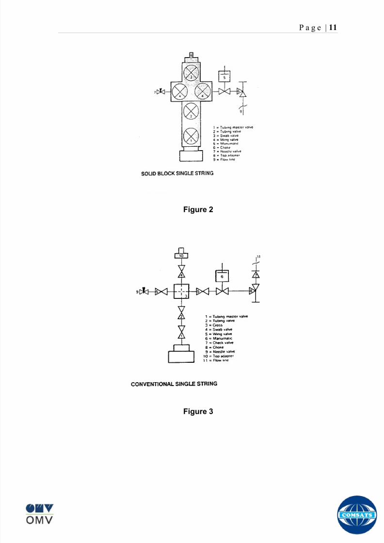
8102019 Gas sweetening Plant
httpslidepdfcomreaderfullgas-sweetening-plant 1562
P a g e | 11
Figure 2
Figure 3
8102019 Gas sweetening Plant
httpslidepdfcomreaderfullgas-sweetening-plant 1662
P a g e | 12
Wellhead Control Panel
Wellhead control panel is key equipment in oil amp gas industry to protect oilfield
facilities and environment from emergency incidents such as wellhead fire which
is one of main control systems to ensure oilfield oil production and transportation
to be safely operation according to international standards and national
regulation Wellhead control panel is composed of hydraulic power unit tubing amp
fitting and instrument valve and electrical control devices Hydraulic power unit
supply hydraulic resource to open and close safety valves including master
valves wing valves and SCSSSV
Its performs
Local OnOff SSV
Remote control SSV through RTU( remote terminal unit)
High-Low pressure sense shut-down automatically
Fusible Plug Anti-fire Shut-down automatically
Function of showing system pressure
Relief Valve shall be installed on each hydraulic circuit to prevent high
pressure
Function of showing hydraulic level and level switch for alarm
Function of defending pressure impact of system
Function of system pressure monitoring (by pressure transmitter of control
panel)
Function of remote emergency shut-down (by magnetic valve of control
panel)
Function of OnOff SSV monitoring (by pressure switch of control loop of
control panel)
8102019 Gas sweetening Plant
httpslidepdfcomreaderfullgas-sweetening-plant 1762
P a g e | 13
Chemical Injection
Chemical injection systems are commonly used in production facilities to prevent
or eliminate a wide range of problems that might negatively affect the production
flow It is done for flow assurance protection of process equipment such as
pipelines or to optimize processes in production facilities
Typical flow assurance chemicals are
Wax inhibitors
Pour point depressants
Asphaltene inhibitors
Corrosion inhibitors
A corrosion inhibitor is a chemical compound that is added to liquid or gas to
decreases the corrosion rate of a material typically a metal or an alloy The
effectiveness of a corrosion inhibitor depends on fluid composition quantity of
water and flow regime Its common mechanism involves formation of a coating
8102019 Gas sweetening Plant
httpslidepdfcomreaderfullgas-sweetening-plant 1862
P a g e | 14
which prevents access of the corrosive substance to the metal The corrosive
agents are generally oxygen hydrogen sulfide and carbon dioxide
At our production site the major risk is corrosion of piping and equipment The
maximum allowable corrosion rate is approximately 02 mm per year and
corrosion rate without inhibitor could be approximately 11 mm per year so the
corrosion protection program is designed to achieve a target corrosion rate of
less than 01 mm per year which is achieved by an inhibitor system efficiency of
99 Inhibitor is injected into the well stream flow through an atomizing nozzle
located downstream of the respective wellhead coolers at the duplexcarbon steel
interface In normal operation as per NALCO standards chemical (brand name
EC1144B) at rate of frac12 Liter per MMSCFD of gas is being injected into the flow
line of miano15 flow lines made of carbon steel Moreover the composition can
vary depending upon the composition of well fluids and material of pipeline This
method of injection ensures even distribution of the chemical on the interior
surface of the pipeline The individual well sites are equipped with Chemical
Injection Packages comprising of a stainless steel storage tank and two
pneumatic motor driven pumps in parallel Instrument gas is used to drive the
pumps Normally one pump is running with the other standby
Water Conning
Water coning is a term used to describe the mechanism underlying the upward
movement of water into the perforations of a producing well Coning can seriously
impact the well productivity and influence the degree of depletion and the overall
recovery efficiency of the reservoir The specific problems of water coning are
listed below
Costly added water handling
Gas production from the original or secondary gas cap reduces pressure
Reduced efficiency of the depletion mechanism
The water is often corrosive and its disposal costly
The affected well may be abandoned early
Loss of the total field overall recovery
8102019 Gas sweetening Plant
httpslidepdfcomreaderfullgas-sweetening-plant 1962
P a g e | 15
Therefore conning has an important influence on operations recovery and
economics The phenomena is shown in picture below
Corrosion
Corrosion is referred as chemical deterioration of a metal Commonly this
means loss of electrons of metals reacting with water and oxygen
Weakening of iron due to oxidation of the iron atoms is a well-known
example of electrochemical corrosion This is commonly known as
rust Most structural alloys corrode merely from exposure to moisture
in the air but the process can be strongly affected by exposure to
certain substances Corrosion can be concentrated locally to form a pit
or crack or it can extend across a wide area to produce general
deterioration (uniform corrosion)
The following reaction takes place at the active sites
2Fe =gt 2Fe++ + 4e-
The free electrons travel through the metal path to the less active sites where
the following reaction takes place
O2 + 4e- + 2H20 =gt 4 OH-
8102019 Gas sweetening Plant
httpslidepdfcomreaderfullgas-sweetening-plant 2062
P a g e | 16
Recombination of these ions at the active surface produce the following
reaction which yields the iron-corrosion product ferrous hydroxide
2Fe + O2 + 2H2O =gt 2Fe (OH) 2
CORROSION PROTECTION SYSTEM
Coatings and painting
Painting and the application of enamel bitumen and PVC
coating are the most common anti-corrosion treatments They
work by providing a barrier of corrosion-resistant material
between the damaging environment and the structural material
Corrosion Inhibitors
Corrosion inhibitor is injected into the flow lines as mentioned in
detail on page 8
Cathodic Protection
Cathodic Protection (CP) is a technique used to control the corrosion of a
metal surface by making it the cathode of an electrochemical cell It
converts all of the anodic (active) sites on the metal surface to cathodic
(passive) sites by supplying electrical current (or free electrons) from an
alternate source It is accomplished in two ways
a) A simple method of protection connects protected metal to a more easily
corroded sacrificial metal to act as the anode The sacrificial metal then
corrodes instead of the protected metal The process is similar to a simple
DC cell in which the more active metal becomes the anode and corrodes
whereas the less active metal becomes the cathode and is protected
b) For larger structures galvanic anodes cannot economically deliver enough
current to provide protection Therefore impressed current cathodic
protection (ICCP) systems are used These consist of anodes connected
to a DC power source In remote areas power sources such as solar
panels may be used The output DC negative terminal is connected to the
8102019 Gas sweetening Plant
httpslidepdfcomreaderfullgas-sweetening-plant 2162
8102019 Gas sweetening Plant
httpslidepdfcomreaderfullgas-sweetening-plant 2262
P a g e | 18
frequently to limit liquid holdup and minimize the slug volumes of liquid which can
be generated by the system
Coating
Pigs may be used to apply internal pipe coatings such as epoxy coating
materials in operating pipelines Pigs may also be used with corrosion inhibitors
to distribute and coat the entire internal wetted perimeter
Inspection
Pigs are being used more frequently as inspection tools Gauging or sizing pigs
are typically run following the completion of new construction or line repair to
determine if there are any internal obstacles bends or buckles in the pipe Pigs
can also be equipped with cameras to allow viewing of the pipe internals
Electronic intelligent or smart ldquopigsrdquo that use magnetic and ultrasonic systems
have been developed and refined that locate and measure internal and external
corrosion pitting dents buckles and any other anomalies in the pipe wall
Intelligent pigs
The accuracy of location and measurement of anomalies by the intelligent pigs
has continued to improve Initially the electronics and power systems were so
large that intelligent pigs could be used only in lines 30 in and greater in size
The continued sophistication and miniaturization of the electronic systems used
in the intelligent pigs has allowed the development of smaller pigs that can be
used in small-diameter pipelines Newly enacted DOT pipeline-integrity
regulations and rules acknowledge the effectiveness of the intelligent pigs and
incorporate their use in the pipeline-integrity testing process
Compressors
A gas compressor is a mechanical device that increases the pressure of a gas by
reducing its volume Gas pressure is increased by forcing gas molecules together
to reduce gas volume When volume is reduced gas pressure increases
All gases have large spaces among their molecules These spaces could be
enhanced further and decreased by doing some work Work done which is used
8102019 Gas sweetening Plant
httpslidepdfcomreaderfullgas-sweetening-plant 2362
P a g e | 19
for the enhancement of these spaces is called expansion and work done to
minimize these spaces is called compression All gases while expansion
produces cooling effect and while compression of gases raises there
temperature Compression is a term used to force gases to occupy smaller
volumes by increasing their pressure Volume of gases is interlinked with
temperature and pressure of the gas which is cleared by 2 laws govern gas
compressions
Boyles Law
Charles Law
The main types of compressor are listed below
Front End Compressor
The plant currently processes gas from a number of wells The flow and pressure
from some of these wells (currently K-10 K-11 amp K-12) has declined and they
cannot be fed directly into the Central Processing Facility To recover the
maximum gas reserves from these wells a Front End Compressor is employed
The compressor is a two stage double acting gas engine driven reciprocating
(PT) compressor Double acting means that gas is compressed on each end of
the piston It normal operates with a speed range of 600 to 900 RPM and isequipped with four compressor cylinders two for each stage Each cylinder is
8102019 Gas sweetening Plant
httpslidepdfcomreaderfullgas-sweetening-plant 2462
P a g e | 20
also equipped with a variable volume head end pocket
In case of compressor emergency shutdown the production chokes and the
Upper Master Valves on the on line wells will close and operator will be notified in
central control room Sweet gas from gas distribution network is used to operate the
gas engine driver of the compressor package The detailed scheme of working is
shown in figure (page 22 )
PT Reciprocating Compressor
The mechanical cycle of piston tube reciprocating compressor comprises four
strokes the expansion stroke the intake stroke the compression stroke and the
discharge stroke
Expansion Stroke
As the piston moves back on the expansion stroke the chamber volume
increases and the pressure drop As the pressure drops the discharge valve
closes since there is greater pressure in the discharge line than in the chamber
Intake Stroke
As the piston moves back during the intake stroke the pressure decreases until it
is less than the pressure in the inlet line This higher intake pressure opens the
inlet valve and gas rushes into the cylinder equalizing the pressure there with
the intake pressure The compression chamber is now at or near the intake
pressure
Compression Stroke
The piston now starts the compression stroke by moving forward decreasing the
chamber volume and increasing the pressure The increased pressure is now
higher than the intake pressure causing the intake valve to close
Discharge Stroke
The piston continues to move to the left during the discharge stroke This creates
an increase in chamber pressure until it is greater than the discharge pressure
When this happens the Discharge valve opens and the compressed air from the
8102019 Gas sweetening Plant
httpslidepdfcomreaderfullgas-sweetening-plant 2562
P a g e | 21
cylinder goes into the discharge line The compression cycle is then repeated
from the stage
Compressor Capacity
The capacity of the compressor depends upon cylinder displacement That
displacement is simply the volume that the piston displaces (moves) as it travels
from one end of the cylinder to the other Capacity and displacement is equal to
the cross-sectional area of the cylinder times the length of the stroke
Lubrication and Cooling
Lubricating oil is circulated through the system by a gear pump which is chain
driven from the engine crank shaft The oil pump is mounted on the engine front
housing
The pump operates between 30 - 40 psig
8102019 Gas sweetening Plant
httpslidepdfcomreaderfullgas-sweetening-plant 2662
P a g e | 22
A circulating pump deliver cooling water to the water jackets in the cylinder block
flowing around the cylinder liners and is directed into the cylinder heads Each
cylinder head has water cooled exhaust elbows which outlet the water into the
water cooled exhausts From the end of engine the water flows to compressor
1st and 2nd stage cylinders and compressor lube oil cooler (LOwater heat
exchanger) The water from the compressor cylinder and lube oil cooler returns
to engine water cooled exhaust
Figure Flow diagram of Front End Compressor
8102019 Gas sweetening Plant
httpslidepdfcomreaderfullgas-sweetening-plant 2762
P a g e | 23
Centrifugal Compressor
Centrifugal compressors are machines in which velocity and pressure given to air
or gas in a radial direction by one or more impellers diffuser combination In a
centrifugal compressor the mechanical energy is increased by centrifugal action
The gas enters the suction eye of a high speed rotary element called the impeller
which carries radial vanes integrally cast in it As the impeller rotates the blades
of the impeller force the gas outward from the center the impeller to the outer rim
of impeller the increase in velocity of the gas creates a flow pressure area at the
eye of the impeller The gas at the outer rim of the impeller is forced in to a
passage way called a diffuser where the velocity decreases in the pressure of the
gas
Inlet
The inlet to a centrifugal compressor is typically a simple pipe It may include
features such as a valve and both pressure and temperature instrumentation
Centrifugal impeller
The key component that makes a compressor centrifugal is the centrifugal
impeller shown above It is the impellers rotating set of vanes (or blades) that
gradually raises the energy of the working gas This is identical to an axial
compressor with the exception that the gases can reach higher velocities and
energy levels through the impellers increasing radius
8102019 Gas sweetening Plant
httpslidepdfcomreaderfullgas-sweetening-plant 2862
P a g e | 24
Diffuser
The next key component to the simple centrifugal compressor is the diffuser
Downstream of the impeller in the flow path it is the diffusers responsibility to
convert the kinetic energy (high velocity) of the gas into pressure by gradually
slowing (diffusing) the gas velocity
SEPERATORS
A well-stream is a mixture of gases hydrocarbon liquids water solids and
contaminants Due to variations in pressure and temperature gases evolve from
the liquids water vapor condenses and some of the well-stream changes to liquid
and free gas The separation of well-stream fluids takes place in a separator This
pressure vessel is manufactured in three forms
1 horizontal
2 vertical
3 spherical
To help separation the vessel is normally designed with a series of internal
fittings These fittings are built into the separator to ensure total phase separation
of the well-stream
In gas plants separators are given alternative names due to the function they
perform in the process system A scrubber does a similar job to a knockout drum
However the scrubber usually separates a stream containing high gas-to-liquid
ratios The knockout drum is used where a high degree of liquids are entrained in
the gas
Fluid flow from a well can include gas condensable liquid vapors water water
vapor crude oil and solids As well-stream fluids reach ground level where
pressure is lower than in the reservoir the capacity of the liquid to hold gas in
solution decreases and gas separates out of the oil
Separation depends upon the effect of gravity to separate liquids For adequate
separation one fluid must be lighter than the other fluid For example distillates
8102019 Gas sweetening Plant
httpslidepdfcomreaderfullgas-sweetening-plant 2962
P a g e | 25
(gasoline kerosene etc) and crude oil will not separate in a vessel because they
tend to dissolve in each other Because a separator basically depends upon
gravity to separate the fluids the ease with which separation takes place
depends upon the difference in density of the fluids
Droplets of liquid will separate from gas provided
a) The gas remains in the separator long enough
b) The gas flow remains constant to provoke separation
The difference in density between a gas and liquid will therefore determine the
maximum flow rate of liquid in the vessel
Figure Two phase horizontal separator
Gas bubbles in the liquid will break out in some oil field applications in 30 to 60
seconds Consequently the separator is designed so that the liquid remains in
the vessel for 30 to 60 seconds The length of time that a liquid remains in the
vessel is called its residence time Residence time differs widely from field to field
depending upon viscosity and API Gravity
Another important factor which must be considered is temperature Generally a
decrease in operating temperature will increase the liquid recovery in a separator
8102019 Gas sweetening Plant
httpslidepdfcomreaderfullgas-sweetening-plant 3062
P a g e | 26
as the gas condenses By reducing the pressure on the fluid flash separation
occurs resulting in a flow through the separator which is controlled by external
instrumentation
COALESCENCE
Another important principle in fluid separation is that of coalescence This means
the coming together of liquid droplets created by the force of gravity
A common example of coalescing occurs when drops of water form on the
windshield of a car as it is driven in fog As the tiny drops or water which make up
the fog strike the windshield they combine and eventually form a drop large
enough to run down the glass
Several of the internal devices of a separator such as deflector plates
straightening vanes and even the vessel walls are forms of coalescers In each
vessel drops of liquid adhere to the surface of the device and combine with other
8102019 Gas sweetening Plant
httpslidepdfcomreaderfullgas-sweetening-plant 3162
P a g e | 27
drops until the drop is large enough to fall out The effectiveness of separation
will also depend upon the total amount of coalescing surface area that is present
There are many different types of separators used in the Oil amp Gas industry
Consequently separators are manufactured with one two or several internal
fittings depending on their use and quick removal of these fluids from the vessel
DEFLECTOR PLATES
These are fitted in front of the inlet to the separator and can be net or
dish-shaped Their purpose is to absorb the impact of the incoming fluids and to
encourage the separation of gas and liquids They also slow the flow rate of the
liquids through the vessel
WEIRS
A weir is a metal wall which is fitted across the inside of the vessel normally to a
height of 50 of the overall height of the separator Its purpose is to assist the
process of three phase separation The inlet fluids (oil plus water) are given time
to separate in the liquid accumulation section The water level (interface) is
normally controlled at 50 of the height of the weir Oil floating on the wateroverflows the weir and accumulates in the small oil compartment where it is
drawn off under level control
CENTRIFUGAL DEVICES
These are used in both vertical and horizontal separators for gas-liquid
separation The device imparts a swirling motion to the fluids entering the vessel
Centrifugal force causes the heavier liquids to travel outwards towards the walls
of the vessel and the lighter gases to flow up the centre Centrifugal devices are
also known as cyclones
VORTEX BREAKERS
When liquid flows through a drain outlet a vortex (whirlpool) will form This can
be seen when we pull the plug from a sink or bath tub The same would happen
as water and oil flow from the separator This condition a vortex could allow gas
to flow down the centre of the whirlpool and enter the liquid phase causing
8102019 Gas sweetening Plant
httpslidepdfcomreaderfullgas-sweetening-plant 3262
P a g e | 28
pressurizing of tanks etc To stop this happening vortex breakers are fitted to all
liquid outlets Although they come in a number of different designs vortex
breakers all serve the same purpose - to prevent a whirlpool from forming
MIST OR DEMISTER PADS
The gas which is released from the fluids in the separator still contains droplets of
oil and water which coalesce and fall when the drops get large enough The
demister pad assists in this process Made from knitted wire and contained within
a sturdy frame it causes the gas to continually change its direction of flow
Because gas changes direction far easier than liquid the gas will flow around
each strand of wire whilst the liquid entrained in the gas stream will continue and
stick to the wire
COALESCING PLATES
There are several different forms of coalescing devices the most common of
which are coalescing plates These plates are mounted in the flow stream of the
fluids and assist in breaking down oil-water emulsions The fluid is forced to
follow a path that constantly changes direction This causes the water droplets to
gather together or coalesce and fall to the bottom of the separator The same
principle is used to separate gas and oil mixtures when the oil droplets are
induced to coalesce Simply stated every surface within the separator including
the separator walls assists with the coalescing process
STRAIGHTENlNG VANES
These are often fitted to horizontal separators to remove turbulence in the gas
stream after initial separation at the inlet deflector
FLOAT SHEILD
Internal floats are used as level controllers Any agitation of the liquid surface or
the effect of coalesced liquids falling on the float may cause control problems
Therefore a float shield is fitted to enclose the float creating an area of still liquid
8102019 Gas sweetening Plant
httpslidepdfcomreaderfullgas-sweetening-plant 3362
P a g e | 29
MEMBRANES
The gas contains 12 carbon dioxide and 22 ppm of hydrogen sulphide at 115oF
and 1100 psig This needs to be removed before the gas can be exported The
majority of carbon dioxide hydrogen sulphide and water is removed by means of
membranes
Membranes are thin semipermeable barriers that selectively separate some
compounds from others Currently the only commercially workable membranes
used for CO2 removal are polymer based for example cellulose acetate
polyimides polyamides polysulfone polycarbonates and polyetherimide The
membrane does not operate as a filter where small molecules are separated
from larger ones through a medium with pores rather it separates based on how
well different compounds dissolve into the membrane and diffuse through it The
membranes are manufactured in flat sheets consisting of an extremely thin
nonporous layer mounted on a much-thicker and highly porous layer of the same
material providing mechanical strength The flat sheets are combined into a
spiral-wound element (Figure below) Feed gas enters along the side of the
membrane and passes through the feed spacers As the gas travels between
membrane sheets CO2 H2S and H2O permeate through the membrane and are
collected in the permeate tube The driving force for transport is the high-feed
pressure and low-permeate pressures The gas on the feed side that does not
permeate leaves through the side of the element opposite the feed position Once
the membranes have been manufactured into elements six to 12 elements are
joined together and inserted into a tube Multiple tubes are mounted on skids in a
horizontal orientation
8102019 Gas sweetening Plant
httpslidepdfcomreaderfullgas-sweetening-plant 3462
P a g e | 30
Figure Membrane general Working
In high H2S applications most polymers have been shown to have very little
resistance to H2S plasticization (ldquosofteningrdquo of the membrane) and as a
consequence can only be used at very low H2S partial pressure limits Cellulose
acetate membranes in contrast have been shown to be applicable at extreme
H2S partial pressure conditions It is these membranes that have been utilized in
the testing to determine the limits of membrane performance in high H 2S
applications
The primary membranes used in Kadanwari facility are Cellulose acetate
Cellulose acetic acid and acetic anhydride are mixed together and reacted to
form cellulose acetate polymers This process is aided by the addition of a small
amount of sulfuric acid which is subsequently neutralized during processing
However the membranes are bought from UOP (vendor) and installed for use
8102019 Gas sweetening Plant
httpslidepdfcomreaderfullgas-sweetening-plant 3562
P a g e | 31
How membrane work
The basic principle of separation is selectivity of certain components of a mixture
for the membrane For example the cellulose acetate membrane has very high
selectivity for CO2 and H2S as compared to CH4 Therefore such type of
membrane can be used in gas sweetening process
The selectivity is directly related to the Permeability of gas which accounts that
which gas can pass across the membrane more easily In simple words
membranes being polymer materials are made of long chains of molecules The
different structure of polymer materials only allow selective molecules to pass
through them depending upon chemical and physical compatibility Thus
permeability depends upon choice of polymer
The permeability is determined by permeability coefficient (P) and is product of
solubility (S) and diffusivity (D)
P = S D
Solubility
The solubility is mainly determined by ease of condensation Heavy molecules
are more readily condensed Therefore higher molecular weighted molecules will
more easily condensed and therefore have greater solubility
Molecule Molecular weight
CH4 16
H2S 34
CO2 44
8102019 Gas sweetening Plant
httpslidepdfcomreaderfullgas-sweetening-plant 3662
P a g e | 32
Diffusivity
Diffusivity is ease of molecule to penetrate into some material It depends on size
of gas molecule Here size of molecule is not to be confused by molecular weight
it is the size of the structure Eg the size of O2 molecule is smaller than N2
Molecule Molecular Diameter (Ao)
CO2 33
H2S 36
Ch4 40
For cellulose acetate
DCO2DCH4 S CO2S CH4 P CO2P CH4
45 73 308
Chemical degradation
Cellulose acetate polymer is chemically degraded by a process called hydrolysis
which means breaking apart by the addition of water This is a chemical reaction
in which water is added to the cellulose acetate polymer causing the release of
acetic acid molecules This process proceeds stepwise until all the acetate
groups are released resulting in the reformation of cellulose Moreover alcohols
aromatic hydrocarbons or solvents with chlorine nitro benzene or similar
aromatic solvents will harm the membrane It will expand and lose plastification in
contact with them
Effect of Temperature
The permeation rates of all gases increases with increasing temperature
however membrane selectivity for CO2 over hydrocarbon decreases at higher
8102019 Gas sweetening Plant
httpslidepdfcomreaderfullgas-sweetening-plant 3762
P a g e | 33
temperature Consequently CO2 removal will improve as operating temperature
increases but hydro carbon recovery will decrease
Primary Membrane
The primary membranes comprise of two trains Each train consists of two
sections AB and CD each section consists of a 30 tube membrane skid (A and
C) followed by a 25 tube skid (B and D) The conditioned gas (after pre-
treatment) enters the primary membrane via the particulate filter adjacent to the
skid The gas is fed to the membranes through a common inlet manifold which
supplies primary membranes skids A and C A pressure control loop located
upstream of the manual inlet isolation valve is provided to maintain a constant
supply pressure to the membrane skid and to allow for preheating at the inlet
prior to skid start-up This pressure control loop can also be used during start-up
to control the pressurization of the pretreatment skid and associated pipes to the
primary membranes
The gas passes through membrane skid A the residual gas exiting the membrane
skid is sent to skid B and the permeate to common permeate discharge header An
identical arrangement is provide on the inlet to skid C as provided on skid A Theresidual gas from skid B combines with the residual gas from skid D in a common
discharge header and is then sent to the H2S polishing towers via the feed coolers
on the pre-treatment skid The permeate from skid B is sent to the common
permeate discharge header The permeate discharge header sends the gas to
either the recycle compressor or the vent header via a pressure control loop
Overpressure protection for the membranes is provided by a pressure safety valve
on the supply header to the membrane banks
8102019 Gas sweetening Plant
httpslidepdfcomreaderfullgas-sweetening-plant 3862
P a g e | 34
Secondary (Recycle) Membrane
The recycle membranes comprise of a single train with two skids each with four
banks of membrane tubes The conditioned gas from the discharge of the recycle
pre-treatment skid is routed to the first recycle membrane skid The gas passes
through the membranes the residual gas is fed to primary membrane (skid A) inlet
via feed gas cooler and permeate to the common permeate discharge header An
identical arrangement is provide on the inlet to skid B Permeate from the recycle
membrane skids A and B is routed to the vent header Some portion of permeate is
heated and sent for regeneration in Mem-Guard units Nitrogen purge can be
connected downstream of the inlet isolation valve on each skid to enable the
membrane tubes to be purged and left pressurized during prolonged shutdown
8102019 Gas sweetening Plant
httpslidepdfcomreaderfullgas-sweetening-plant 3962
P a g e | 35
Figure Flow Diagram of Recycle membrane unit
8102019 Gas sweetening Plant
httpslidepdfcomreaderfullgas-sweetening-plant 4062
P a g e | 36
ADVANTAGES OF MEMBRANE SYSTEMS
Membrane systems have major advantages over more-traditional methods of
acid gas removal
Lower capital cost Membrane systems are skid mounted and so the
scope cost and time taken for site preparation are minimal Installation
costs are significantly lower than alternative technologies especially for
remote areas Furthermore no additional facilities for solvent storage and
water treatment needed by other processes are required
Lower operating costs The only major operating cost for single-stage
membrane systems is membrane replacement This cost is significantly
lower than the solvent replacement and energy costs associated with
traditional technologies The improvements in membrane and
pretreatment design allow a longer useful membrane life which further
reduces operating costs The energy costs of multistage systems with
large recycle compressors are usually comparable to those for traditionaltechnologies
Deferred capital investment Often contracted sales-gas flow rates
increase over time as more wells are brought on-line With traditional
technologies the system design needs to take this later production into
account immediately and so the majority of the equipment is installed
before it is even needed The modular nature of membrane systems
means that only the membranes that are needed at start-up need be
installed The rest can be added either into existing tubes or in new skids
only when they are required
Operational simplicity and high reliability Because single-stage
membrane systems have no moving parts they have almost no
8102019 Gas sweetening Plant
httpslidepdfcomreaderfullgas-sweetening-plant 4162
P a g e | 37
unscheduled downtime and are extremely simple to operate They can
operate unattended for long periods of time The addition of a recycle
compressor adds some complexity to the system but still much less than
with a solvent- or adsorbent-based technology Multistage systems can be
operated at full capacity as single-stage systems when the recycle
compressor is down
Good weight and space efficiency Skid construction can be optimized
to the space available This space efficiency is especially important for
offshore environments where deck area is at a premium and is the
reason why so many new offshore developments have chosen to use
membranes for acid gas removal Figure 6 illustrates the space efficiency
of membrane systems The membrane unit in the lower left corner
replaced all the amine and glycol plant equipment shown in the rest of the
picture
Adaptability Because membrane area is dictated by the percentage of
acid gas removal rather than absolute acid gas removal small variations
in feed acid gas content hardly change the sales-gas acid gas
specification For example a system designed for 10 down to 3 acid
gas removal produces a 35 product from a 12 feed gas and a 5
product from a 15 feed gas
Design efficiency The membrane and pretreatment systems integrate a
number of operations such as dehydration CO2 and H2S removal dew-
point control and mercury removal Traditional acid gas removal
technologies require all of these operations as separate processes and
may also require additional dehydration because some technologies
saturate the product stream with water
8102019 Gas sweetening Plant
httpslidepdfcomreaderfullgas-sweetening-plant 4262
P a g e | 38
Power generation The permeate gas from membrane systems can be
used to provide fuel gas for power generation either for a recycle
compressor or other equipment
Ideal for debottlenecking Because expanding solvent- or adsorbent-
based acid gas removal plants without adding additional trains is difficult
an ideal solution is to use membranes for bulk acid gas removal and leave
the existing plant for final cleanup An additional advantage is that the
permeate gas from the membrane system can often be used as fuel for
the existing plant thus avoiding significant increase in hydrocarbon
losses
Environmentally friendly Membrane systems do not involve the
periodic removal and handling of spent solvents or adsorbents Permeate
gases can be flared used as fuel or re-injected into the well Items thatdo need disposal such as spent membrane elements can be incinerated
Ideal for remote locations Many of the factors mentioned above make
membrane systems a highly desirable technology for remote locations
where spare parts are rare and labor unskilled Furthermore solvents
storage and trucking water supply power generation or extensive
infrastructure are not required
Re-injection optimizations Since the permeate stream from the
membrane system can be operated at elevated pressures it is possible to
further pressurize by re-injection compression train
8102019 Gas sweetening Plant
httpslidepdfcomreaderfullgas-sweetening-plant 4362
P a g e | 39
Sorption
Sorption is a physical and chemical process by which one substance becomes
attached to another
It is of two main types
1 Absorption
2 Adsorption
Absorption
Absorption is a physical or chemical phenomenon or process in which atoms
molecules or ions enter some bulk phase ndash gas liquid or solid material This is a
different process from adsorption since molecules undergoing absorption are
taken up by the volume not by the surface (as in the case for adsorption)
Absorption process may be chemical (reactive) or physical (non-reactive)
Physical absorption
Physical absorption or non-reactive absorption is made between two phases ofmatter a liquid absorbs a gas or a solid absorbs a liquid
When a liquid solvent absorbs a gas mixture or part of it a mass of gas moves
into the liquid For example water may absorb oxygen from the air This mass
transfer takes place at the interface between the liquid and the gas at a rate
depending on both the gas and the liquid This type of absorption depends on the
solubility of gases the pressure and the temperature The rate and amount of
absorption also depend on the surface area of the interface and its duration in
time
When a solid absorbs a liquid mixture or part of it a mass of liquid moves into the
solid For example a clay pot used to store water may absorb some of the water
This mass transfer takes place at the interface between the solid and the liquid
at a rate depending on both the solid and the liquid
8102019 Gas sweetening Plant
httpslidepdfcomreaderfullgas-sweetening-plant 4462
P a g e | 40
Chemical absorption
Chemical absorption or reactive absorption is a chemical reaction between the
absorbed and the absorbing substances Sometimes it combines with physical
absorption This type of absorption depends upon the stoichiometry of the
reaction and the concentration of its reactants
Adsorption
Adsorption is the adhesion of atoms ions or molecules from a gas liquid or
dissolved solid to a surface This process creates a film of the adsorbate on the
surface of the adsorbent The binding to the surface is usually weak and
reversible Compounds with color and those that have taste or odor tend to bind
strongly Compounds that vibrate at frequencies in the visible spectrum are very
often are strongly adsorbed on activated carbon
The most common industrial adsorbents are activated carbon silica gel and
alumina because they present enormous surface areas per unit weight
Depending on the nature of attractive forces existing between the adsorbate and
adsorbent adsorption can be classified as
i) Physical adsorption
ii) Chemical adsorption
i) Physical adsorption (Physisorption)
In physical adsorption the forces of attraction between the molecules of the
adsorbate and the adsorbent are of the weak van der Waals type Since the
forces of attraction are weak the process of physisorption can be easily reversed
by heating or decreasing the pressure of the adsorbate (as in the case of gases)
8102019 Gas sweetening Plant
httpslidepdfcomreaderfullgas-sweetening-plant 4562
P a g e | 41
ii) Chemical adsorption (Chemisorption)
In chemisorption the forces of attraction between the adsorbate and the
adsorbent are very strong the molecules of adsorbate form chemical bonds with
the molecules of the adsorbent present in the surface
Adsorption is generally accompanied by release of energy that is most
adsorption processes are exothermic in nature Adsorption is a spontaneous
process therefore its free energy change is negative (∆Glt0) However the
entropy change associated with adsorption is generally negative because the
adsorbate molecules lose their translation freedom when they get attached to the
surface of the adsorbent Therefore in order for ∆G to be negative the enthalpy
change (∆H) must be sufficiently negative such that (∆G=∆H-T∆S) lt 0 This
explanation accounts for exothermic adsorption processes In cases where
endothermic adsorption occurs the entropy change ∆S is sufficiently positive
such that ∆G remains negative
Pre treatment
The main function of pretreatment skid is to provide membrane inlet specification
gas as mentioned by the vendor UOP It removes the contaminants that would
poison the membranes like dust solids (adsorbent particles) lube oil heavy
hydrocarbons etc It consists of
Feed Cooler
Feed Gas Scrubber
Filter Coalescer
Feed Gas Heater
Activated Carbon Guard Filter
Particle Filter
8102019 Gas sweetening Plant
httpslidepdfcomreaderfullgas-sweetening-plant 4662
8102019 Gas sweetening Plant
httpslidepdfcomreaderfullgas-sweetening-plant 4762
P a g e | 43
The regeneration is carried out by heated permeate gas from the recycle
membranes at 450oF The vessel is depressurized to 20 psi and heated gas is
introduced from top The gas carries out the adsorbed contaminants and leaves
the vessel from bottom cleaning the adsorbent This contaminated gas is burnt in
the flare
UOP the vendor of Memguard unit has never disclosed that what substance
MG3 and MG5 exactly are But as mentioned by vendor that both care class of
aluminosilicates Therefore MG3 can be potassium aluminosilicate and MG5 can
be Calcium aluminosilicate These are molecular sieves adsorbents Molecular
sieves are a microporous material which can selectively adsorb gases andliquids They are synthetic zeolites (crystalline metal aluminosilicates) which
upon dehydration can efficiently and selectively remove water or other
solvents The selectivity of a molecular sieve is determined by its pore size
molecules with a critical diameter which is less than the pore size will be
efficiently adsorbed while larger molecules will be excluded
8102019 Gas sweetening Plant
httpslidepdfcomreaderfullgas-sweetening-plant 4862
P a g e | 44
3A Molecular Sieve Adsorbent
The 3A molecular sieve adsorbent has a 3 angstrom (3A) pore size which means
that any molecule that is larger than the 3 angstrom pores will not be adsorbed
The 3A molecular sieve is the potassium type of A crystalline structure and is a
form of alkali Aluminosilicate For a 3A molecular sieve the sequence rate that
adsorption occurs is He Ne N and H2O
Due to the crystalline structure molecular sieves that have a 3 angstrom pore
size have a very high rate of adsorption and properties that promote a longer life
for products treated by the sieve The most common use for the 3A molecular
sieve is to remove water and moisture from materials that are in gas and liquid
form
5A Molecular Sieve Adsorbent
These are molecular sieve adsorbents with a pore size of 5 angstrom (5A) 5A
molecular sieves are unable to adsorb any molecules or impurities that are
smaller than 5A It is calcium form of type A crystalline structure and is form of analkali-aluminosilicate that is most commonly used to separate isomerous alkanes
from normal alkanes and to co-adsorb moisture and water along with carbon
dioxide from gases In additional 5A molecular sieves are used for gaseous
pressure swing adsorption (PSA)mdashthat is to separate particular gases from other
gases
Adsorption of nC4H10
Adsorption of nC4H10
Adsorption of C3H8 to C22H46
Adsorption of Freon-12 (dichlorodifluoromethane)
Natural gas drying
Normal- and iso-paraffin separation
Separation of aromatic
8102019 Gas sweetening Plant
httpslidepdfcomreaderfullgas-sweetening-plant 4962
P a g e | 45
Inlet Composition of Memguard vessel
COMPSOSITION MOLE
CARBON DIOXIDE 1096
MEHTANE 8593
ETHANE 173
PROPANE 023
I-BUTANE 008
N BUTANE 004
PENTANES 004
HEXANE + 000
NITROGEN 076
WATER 007
Outlet Composition of Memguard vessel
COMPSOSITION MOLE
CARBON DIOXIDE 1098
MEHTANE 8608
ETHANE 173
PROPANE 023
I-BUTANE 008N BUTANE 004
PENTANES 004
HEXANE + 000
NITROGENT 076
WATER 000
H2S polisher
The H2S polishing unit has been designed to treat 187 MMscfday of natural gas
containing up to 11 CO2 and 21 ppm H2S where the level of the CO2 and H2S
is reduced using a MemGuard Membrane separation unit The unit is situated
down-stream of the membrane unit and will further reduce the level of H2S in the
processed gas to a sales gas specification of 38 ppm
8102019 Gas sweetening Plant
httpslidepdfcomreaderfullgas-sweetening-plant 5062
P a g e | 46
This process uses three non-regenerable fixed bed absorber vessels using a low
temperature high activity absorbent The absorbent is a mixture of activated
metal oxides (mainly zinc oxide) The three towers can are generally operated in
parallel arrangement but on demand can be used in series (any of alternate
arrangements of A B C vessels) as shown in figure
The higher sales gas flow rate increased the catalyst consumption and
replacement frequency
ZnO + H2S =gt ZnS + H20
Routine samples are taken from the beds to provide a check on each bed
performance and to follow the saturation profile during the absorbent life After
the adsorbent has been fully utilized the adsorption vessels are recharged with
new adsorbent discarding the utilized one in a safe manner
109oF
1215 psig
Before H2S Polishing After H2S Polishing
8102019 Gas sweetening Plant
httpslidepdfcomreaderfullgas-sweetening-plant 5162
P a g e | 47
Figure
H2S Tower
Inlet pipe
4 Drums of 19mm
ceramic Balls
6 Micron mesh
5 Drums of 50mmceramic
1 Drums of19mm ceramic
01 Drums of6mm ceramic
112 drums of
Catalist ZnO
8102019 Gas sweetening Plant
httpslidepdfcomreaderfullgas-sweetening-plant 5262
P a g e | 48
Recycle Compressor
The permeate gas of the primary membrane unit carries recoverable amount of
CH4 It is fed to recycle membrane unit for further CH 4 recovery But the
permeate pressure from primary membranes which has been reduced to 12 psi
must be regenerated to 1200 psi for the gas to be fed again to the system For
this purpose we have employed recycle compressor The compressor is a four
stage centrifugal compressor It is driven by gas turbine of 31200 HP It has 25
MW producing capacity
Figure Recycle Compressor Process Flow Diagram
8102019 Gas sweetening Plant
httpslidepdfcomreaderfullgas-sweetening-plant 5362
P a g e | 49
Sales Gas Compressor
Gas from H2S polishing unit is sent to sales gas compressor where its pressure
is enhanced to 1100 psi so it may be injected to SNGPL high pressure trunk line
Sales gas compressor is single stage gas turbine driven
Figure Process Flow of Sales Gas Compressor
8102019 Gas sweetening Plant
httpslidepdfcomreaderfullgas-sweetening-plant 5462
P a g e | 50
Cooling Towers
A cooling tower is a heat rejection device which extracts waste heat to theatmosphere through the cooling of a water stream to a lower temperature Hot
water from the system enters the cooling tower and is distributed over the fill
(heat transfer surface) Air is induced or forced through the fill causing a small
portion of the water to evaporate This evaporation removes heat from the
remaining water which is collected in the cold water basin and returned to the
system to absorb more heat Each cooling tower line although operating under
the same basic principle of operation is arranged a little differently
Types
Natural draft mdash Utilizes buoyancy via a tall chimney Warm moist air naturally
rises due to the density differential compared to the dry cooler outside air Warm
moist air is less dense than drier air at the same pressure This moist air
buoyancy produces an upwards current of air through the tower
Mechanical draft mdash Uses power-driven fan motors to force or draw airthrough the tower
o Induced draft mdash A mechanical draft tower with a fan at the
discharge (at the top) which pulls air up through the tower The fan
induces hot moist air out the discharge This produces low entering
and high exiting air velocities reducing the possibility of
recirculation in which discharged air flows back into the air intake
o Forced draft mdash A mechanical draft tower with a blower type fan at
the intake The fan forces air into the tower creating high entering
and low exiting air velocities The low exiting velocity is much more
susceptible to recirculation This fanfill geometry is also known as
blow-through
8102019 Gas sweetening Plant
httpslidepdfcomreaderfullgas-sweetening-plant 5562
P a g e | 51
Forced Draft Cooling Tower Vs Induced Draft Cooling Tower
Induced Draft Cooling Tower have the ability to handle large water flow
rate than Forced Draft Cooling Tower
Induced Draft Cooling Tower is suitable for large cell sizes and fan sizes
as compared with Forced Draft Larger fan size may result in greater
efficiency and consequently lower power and sound level
Forced Draft Cooling Tower can be square or rectangular type only
however Induced Draft Cooling Towers can be round square or
rectangular type
Induced Draft Cooling Tower uses more compact ground area than Forced
Draft Cooling Tower equivalent capacity due to absence of fan on one
side
Fan equipment is warm exhaust air is less liable to icing up in winter
operation (Cold Countries)
Higher velocity in Forced Draft Cooling Tower cause drop in suspension
and cause additional static resistance to system
Configuration
There are two main configurations of factory assembled cooling towers crossflow
and counterflow In crossflow cooling towers the water flows vertically down the
fill as air flows horizontally across In counterflow cooling towers the water flows
vertically down the fill as air flows vertically up
Crossflow Configuration Counterflow Configuration
8102019 Gas sweetening Plant
httpslidepdfcomreaderfullgas-sweetening-plant 5662
P a g e | 52
Drift mdash Water droplets that are carried out of the cooling tower with the exhaust
air Drift droplets have the same concentration of impurities as the water entering
the tower The drift rate is typically reduced by employing baffle-like devices
called drift eliminators through which the air must travel after leaving the fill and
spray zones of the tower
Blow-out mdash Water droplets blown out of the cooling tower by wind generally at
the air inlet openings Water may also be lost in the absence of wind through
splashing or misting Devices such as wind screens louvers splash deflectors
and water diverters are used to limit these losses
Blow-down mdash The portion of the circulating water flow that is removed (usually
discharged to a drain) in order to maintain the amount of Total Dissolved Solids
(TDS) and other impurities at an acceptably low level Higher TDS concentration
in solution may result from greater cooling tower efficiency However the higher
the TDS concentration the greater the risk of scale biological growth and
corrosion
Make-up mdash The water that must be added to the circulating water system in
order to compensate for water losses such as evaporation drift loss blow-out
blow-down etc
Approach mdash The approach is the difference in temperature between the cooled-
water temperature and the entering-air wet bulb temperature
Range mdash The range is the temperature difference between the warm water inlet
and cooled water exit
Fill mdash Inside the tower fills are added to increase contact surface as well as
contact time between air and water to provide better heat transfer The efficiency
of the tower depends on the selection and amount of fill
8102019 Gas sweetening Plant
httpslidepdfcomreaderfullgas-sweetening-plant 5762
P a g e | 53
There are two types of fills that may be used
o Film type fill (causes water to spread into a thin film)
o Splash type fill (breaks up falling stream of water and interrupts its
vertical progress)
Important
Scale build up is controlled by adding chemicals to the cooling loop and diluting
the concentration by blow down and make-up Following chemicals are added to
the Cooling to control CorrosionSale and microbial growth
Corrosion Inhibitor To control corrosion in the Cooling system
Dispersant To kept ions in suspension to avoid settle down and buildup
Sodium hypo Chlorite To Control microbial Growth
Acid To control Alkalinity in the system
High Stress Polymer To run the system at higher conductivity It is a
multifunctional polymer for Zinc amp Phosphate stabilization in cooling tower
Fin Fan Cooler
Fin fan heat exchanger is simply a pressure vessel which cools a circulating fluid
within finned tubes by forcing ambient air over the exterior of the tubes A
common example of an air cooler is a carrsquos radiator Fin Fan Coolers are used in
any application where large quantities of heat need to be transferred This
includes chemical and petrochemical industries power stations waste-to-energy
facilities as well as steelworks
Fin Fan Cooler are used for two primary reasons
They increase plant efficiency
They are a green solution as compared to cooling towers and shell and
tube heat exchangers because they do not require an auxiliary water
8102019 Gas sweetening Plant
httpslidepdfcomreaderfullgas-sweetening-plant 5862
P a g e | 54
supply (water lost due to drift and evaporation plus no water treatment
chemicals are required)
Figure General Overview of Fin Fan Cooler
Produced Water
The produced water system receives liquid from the equipment Miano slug
catcher train 1 and 2 inlet separators and is fed to three phase separator where
water oil and gas is separated The gases produced are burnt in incinerator
whereas hydrocarbon liquid is stored to be sold Liquid from compressors
recycle inlet separator recycle feed scrubber high and low pressure slug
catchers is passed to degasser Separated water is injected down the earth
Incinerator
The term incinerate means to burn something until nothing is left but ashes An
incinerator is a unit or facility used to burn trash and other types of waste until it is
reduced to ash An incinerator is constructed of heavy well-insulated materials
so that it does not give off extreme amounts of external heat The high levels of
heat are kept inside the furnace or unit so that the waste is burned quickly and
efficiently If the heat were allowed to escape the waste would not burn as
completely or as rapidly
8102019 Gas sweetening Plant
httpslidepdfcomreaderfullgas-sweetening-plant 5962
P a g e | 55
Control System
The plant is controlled at CCR (Central Control Room) by PLCs (Programmable
Logic Controllers) through fiber optic control line All control parameters are
received at LER (Local Equipment Room) via two optic fiber control lines One
being primary and other secondary operating in redundancy ie if primary fails
control shifts to secondary These control parameters are sent to CCR via single
optic fiber cable
Safety System
Wellheads and Gas Processing Plant have their own Fire amp Gas detection
systems emergency shutdown (ESD) Plant has a fault tolerant controller It is
based on Triple Modular Redundant (TMR) architecture manufactured by
Triconex The TMR system is based on three isolated parallel control systems
integrated into one system The system operates on a two out of three voting
principle which provides high integrity error free uninterrupted operation with no
single point of failure The TMR receives inputs from Process Sensors Manual
Switches Fire amp Gas Detectors Packaged Equipment Control Systems and
Product Exporting Facilities The TMR carries out cause and effect processing on
the data received and where necessary produces output signals Outputs from
the TMR are hard wired directly to ESD shutdown and blow down valve
solenoids motor control instrumentelectrical interfaces to control electrical
drives package equipment logic control systems manifold area as well as
telecoms
The operator in central control room is able to accept alarms and once the fault
has been cleared reset the input All the control systems are centralized to a
single interface All the PLCs (Programmable Logic Controllers) communicate with
the servers and servers communicate with the clients through Ethernet connectivity
Centralization eases the navigation of different systems at a common interface
Emergency Shutdown
The ESD system receives inputs from field mounted instrumentation on the process
8102019 Gas sweetening Plant
httpslidepdfcomreaderfullgas-sweetening-plant 6062
P a g e | 56
and utility equipment and initiates executive actions appropriate to the level of ESD
The system is an Active system which is in standby and will activate when in an
alarm or fault condition The Kadanwari Gas Process Facility ESD system is
comprised of five (5) levels The emergency severity decreases with increasing ESD
level number
ESD 1
This shutdown level is automatically initiated by fire major gas leak or a detected
toxic atmosphere in the process area of the plant or manually from CCR A level 1
shutdown will cause all production to cease close all emergency shutdown
valves stop the process and shutdown of the main power generation The
emergency vent valves to the stack will open and in addition all equipment of zone 1
certified will be isolated This is the highest level of ESD and will cause the following
to occur
All Shutdown Valves (SDVs) on the process facility will close All slowdown Valves (BDVs) on the process facility will open
All Main Gas Driven Generators will be tripped
Emergency Diesel Generator will start
All electrical power to process and utility rotating equipment will be
isolated
Wellhead Choke Valves Close Wing Valves Close Upper Master Valve
(UMV) Close
ESD 2
This shutdown level is activated automatically if a major process or utility failure
occurs or manually from CCR All production to the plant from the wellhead is
stopped All emergency shutdown valves trip to their fail safe position
Venting shall be as specified This level of ESD will cause the following to occur
8102019 Gas sweetening Plant
httpslidepdfcomreaderfullgas-sweetening-plant 6162
P a g e | 57
All Shutdown Valves (SDVs) on the process facility will close
All electrical power to process and utility rotating equipment will be
isolated
Wellhead Choke Valve Close Wing Valves Close and Upper Master Valve(UMV) Close
ESD 3
The level 3 shutdown isolates and stops a single process train only Production
continues via the other train This ESD level is initiated by process conditions or
operator at local panel This level of ESD will cause the following to occur
ESD 3A Train 1 production to cease
ESD 3B Train 2 production to cease
All online wellhead choke valves go to minimum flow ie (1O )
ESD 4
A level 4 shutdown shall cease all production from an entire field either
Kadanwari or Miano upstream of the associated slug catchers ESD 4K for
Kadanwari amp ESD 4M for Miano This ESD level is initiated automatically by slug
catcher abnormal process conditions This level of ESD will cause the following
to occur
All SDVs close isolating the relevant slug catcher and its upstream gas
production facility from the Kadanwari Gas Processing Plant
All Wellhead Choke Valves Close Wing Valves Close and Upper MasterValves (UMV) of the relevant gas production facility Close
A parallel timer is provided to close within 10 second if not closed in given
time SSSV seals the well
ESD 5
A level 5 shutdown represents equipment shutdown for the protection of the
individual equipment without any change in the process This level of ESD is for the
protection of various pieces of equipment and is initiated by its own inputs eg
8102019 Gas sweetening Plant
httpslidepdfcomreaderfullgas-sweetening-plant 6262
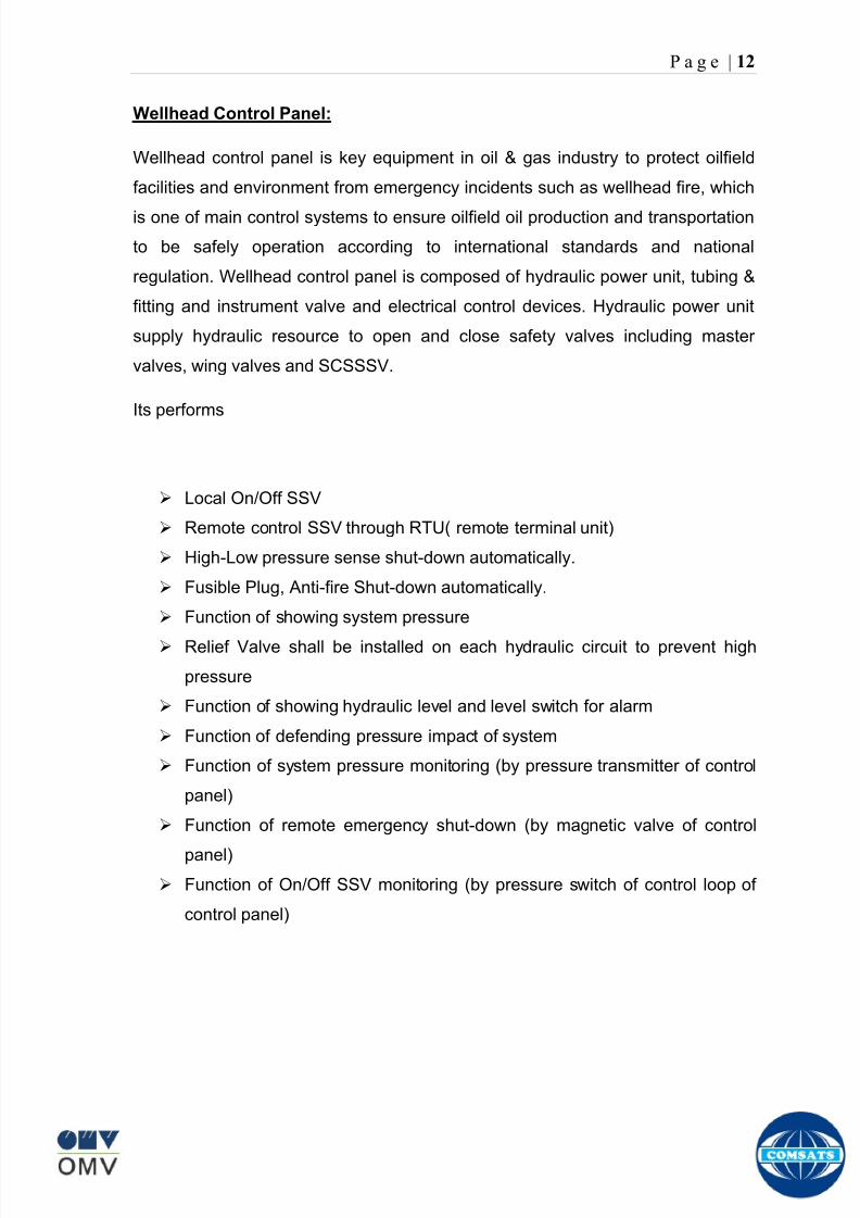
8102019 Gas sweetening Plant
httpslidepdfcomreaderfullgas-sweetening-plant 1662
P a g e | 12
Wellhead Control Panel
Wellhead control panel is key equipment in oil amp gas industry to protect oilfield
facilities and environment from emergency incidents such as wellhead fire which
is one of main control systems to ensure oilfield oil production and transportation
to be safely operation according to international standards and national
regulation Wellhead control panel is composed of hydraulic power unit tubing amp
fitting and instrument valve and electrical control devices Hydraulic power unit
supply hydraulic resource to open and close safety valves including master
valves wing valves and SCSSSV
Its performs
Local OnOff SSV
Remote control SSV through RTU( remote terminal unit)
High-Low pressure sense shut-down automatically
Fusible Plug Anti-fire Shut-down automatically
Function of showing system pressure
Relief Valve shall be installed on each hydraulic circuit to prevent high
pressure
Function of showing hydraulic level and level switch for alarm
Function of defending pressure impact of system
Function of system pressure monitoring (by pressure transmitter of control
panel)
Function of remote emergency shut-down (by magnetic valve of control
panel)
Function of OnOff SSV monitoring (by pressure switch of control loop of
control panel)
8102019 Gas sweetening Plant
httpslidepdfcomreaderfullgas-sweetening-plant 1762
P a g e | 13
Chemical Injection
Chemical injection systems are commonly used in production facilities to prevent
or eliminate a wide range of problems that might negatively affect the production
flow It is done for flow assurance protection of process equipment such as
pipelines or to optimize processes in production facilities
Typical flow assurance chemicals are
Wax inhibitors
Pour point depressants
Asphaltene inhibitors
Corrosion inhibitors
A corrosion inhibitor is a chemical compound that is added to liquid or gas to
decreases the corrosion rate of a material typically a metal or an alloy The
effectiveness of a corrosion inhibitor depends on fluid composition quantity of
water and flow regime Its common mechanism involves formation of a coating
8102019 Gas sweetening Plant
httpslidepdfcomreaderfullgas-sweetening-plant 1862
P a g e | 14
which prevents access of the corrosive substance to the metal The corrosive
agents are generally oxygen hydrogen sulfide and carbon dioxide
At our production site the major risk is corrosion of piping and equipment The
maximum allowable corrosion rate is approximately 02 mm per year and
corrosion rate without inhibitor could be approximately 11 mm per year so the
corrosion protection program is designed to achieve a target corrosion rate of
less than 01 mm per year which is achieved by an inhibitor system efficiency of
99 Inhibitor is injected into the well stream flow through an atomizing nozzle
located downstream of the respective wellhead coolers at the duplexcarbon steel
interface In normal operation as per NALCO standards chemical (brand name
EC1144B) at rate of frac12 Liter per MMSCFD of gas is being injected into the flow
line of miano15 flow lines made of carbon steel Moreover the composition can
vary depending upon the composition of well fluids and material of pipeline This
method of injection ensures even distribution of the chemical on the interior
surface of the pipeline The individual well sites are equipped with Chemical
Injection Packages comprising of a stainless steel storage tank and two
pneumatic motor driven pumps in parallel Instrument gas is used to drive the
pumps Normally one pump is running with the other standby
Water Conning
Water coning is a term used to describe the mechanism underlying the upward
movement of water into the perforations of a producing well Coning can seriously
impact the well productivity and influence the degree of depletion and the overall
recovery efficiency of the reservoir The specific problems of water coning are
listed below
Costly added water handling
Gas production from the original or secondary gas cap reduces pressure
Reduced efficiency of the depletion mechanism
The water is often corrosive and its disposal costly
The affected well may be abandoned early
Loss of the total field overall recovery
8102019 Gas sweetening Plant
httpslidepdfcomreaderfullgas-sweetening-plant 1962
P a g e | 15
Therefore conning has an important influence on operations recovery and
economics The phenomena is shown in picture below
Corrosion
Corrosion is referred as chemical deterioration of a metal Commonly this
means loss of electrons of metals reacting with water and oxygen
Weakening of iron due to oxidation of the iron atoms is a well-known
example of electrochemical corrosion This is commonly known as
rust Most structural alloys corrode merely from exposure to moisture
in the air but the process can be strongly affected by exposure to
certain substances Corrosion can be concentrated locally to form a pit
or crack or it can extend across a wide area to produce general
deterioration (uniform corrosion)
The following reaction takes place at the active sites
2Fe =gt 2Fe++ + 4e-
The free electrons travel through the metal path to the less active sites where
the following reaction takes place
O2 + 4e- + 2H20 =gt 4 OH-
8102019 Gas sweetening Plant
httpslidepdfcomreaderfullgas-sweetening-plant 2062
P a g e | 16
Recombination of these ions at the active surface produce the following
reaction which yields the iron-corrosion product ferrous hydroxide
2Fe + O2 + 2H2O =gt 2Fe (OH) 2
CORROSION PROTECTION SYSTEM
Coatings and painting
Painting and the application of enamel bitumen and PVC
coating are the most common anti-corrosion treatments They
work by providing a barrier of corrosion-resistant material
between the damaging environment and the structural material
Corrosion Inhibitors
Corrosion inhibitor is injected into the flow lines as mentioned in
detail on page 8
Cathodic Protection
Cathodic Protection (CP) is a technique used to control the corrosion of a
metal surface by making it the cathode of an electrochemical cell It
converts all of the anodic (active) sites on the metal surface to cathodic
(passive) sites by supplying electrical current (or free electrons) from an
alternate source It is accomplished in two ways
a) A simple method of protection connects protected metal to a more easily
corroded sacrificial metal to act as the anode The sacrificial metal then
corrodes instead of the protected metal The process is similar to a simple
DC cell in which the more active metal becomes the anode and corrodes
whereas the less active metal becomes the cathode and is protected
b) For larger structures galvanic anodes cannot economically deliver enough
current to provide protection Therefore impressed current cathodic
protection (ICCP) systems are used These consist of anodes connected
to a DC power source In remote areas power sources such as solar
panels may be used The output DC negative terminal is connected to the
8102019 Gas sweetening Plant
httpslidepdfcomreaderfullgas-sweetening-plant 2162
8102019 Gas sweetening Plant
httpslidepdfcomreaderfullgas-sweetening-plant 2262
P a g e | 18
frequently to limit liquid holdup and minimize the slug volumes of liquid which can
be generated by the system
Coating
Pigs may be used to apply internal pipe coatings such as epoxy coating
materials in operating pipelines Pigs may also be used with corrosion inhibitors
to distribute and coat the entire internal wetted perimeter
Inspection
Pigs are being used more frequently as inspection tools Gauging or sizing pigs
are typically run following the completion of new construction or line repair to
determine if there are any internal obstacles bends or buckles in the pipe Pigs
can also be equipped with cameras to allow viewing of the pipe internals
Electronic intelligent or smart ldquopigsrdquo that use magnetic and ultrasonic systems
have been developed and refined that locate and measure internal and external
corrosion pitting dents buckles and any other anomalies in the pipe wall
Intelligent pigs
The accuracy of location and measurement of anomalies by the intelligent pigs
has continued to improve Initially the electronics and power systems were so
large that intelligent pigs could be used only in lines 30 in and greater in size
The continued sophistication and miniaturization of the electronic systems used
in the intelligent pigs has allowed the development of smaller pigs that can be
used in small-diameter pipelines Newly enacted DOT pipeline-integrity
regulations and rules acknowledge the effectiveness of the intelligent pigs and
incorporate their use in the pipeline-integrity testing process
Compressors
A gas compressor is a mechanical device that increases the pressure of a gas by
reducing its volume Gas pressure is increased by forcing gas molecules together
to reduce gas volume When volume is reduced gas pressure increases
All gases have large spaces among their molecules These spaces could be
enhanced further and decreased by doing some work Work done which is used
8102019 Gas sweetening Plant
httpslidepdfcomreaderfullgas-sweetening-plant 2362
P a g e | 19
for the enhancement of these spaces is called expansion and work done to
minimize these spaces is called compression All gases while expansion
produces cooling effect and while compression of gases raises there
temperature Compression is a term used to force gases to occupy smaller
volumes by increasing their pressure Volume of gases is interlinked with
temperature and pressure of the gas which is cleared by 2 laws govern gas
compressions
Boyles Law
Charles Law
The main types of compressor are listed below
Front End Compressor
The plant currently processes gas from a number of wells The flow and pressure
from some of these wells (currently K-10 K-11 amp K-12) has declined and they
cannot be fed directly into the Central Processing Facility To recover the
maximum gas reserves from these wells a Front End Compressor is employed
The compressor is a two stage double acting gas engine driven reciprocating
(PT) compressor Double acting means that gas is compressed on each end of
the piston It normal operates with a speed range of 600 to 900 RPM and isequipped with four compressor cylinders two for each stage Each cylinder is
8102019 Gas sweetening Plant
httpslidepdfcomreaderfullgas-sweetening-plant 2462
P a g e | 20
also equipped with a variable volume head end pocket
In case of compressor emergency shutdown the production chokes and the
Upper Master Valves on the on line wells will close and operator will be notified in
central control room Sweet gas from gas distribution network is used to operate the
gas engine driver of the compressor package The detailed scheme of working is
shown in figure (page 22 )
PT Reciprocating Compressor
The mechanical cycle of piston tube reciprocating compressor comprises four
strokes the expansion stroke the intake stroke the compression stroke and the
discharge stroke
Expansion Stroke
As the piston moves back on the expansion stroke the chamber volume
increases and the pressure drop As the pressure drops the discharge valve
closes since there is greater pressure in the discharge line than in the chamber
Intake Stroke
As the piston moves back during the intake stroke the pressure decreases until it
is less than the pressure in the inlet line This higher intake pressure opens the
inlet valve and gas rushes into the cylinder equalizing the pressure there with
the intake pressure The compression chamber is now at or near the intake
pressure
Compression Stroke
The piston now starts the compression stroke by moving forward decreasing the
chamber volume and increasing the pressure The increased pressure is now
higher than the intake pressure causing the intake valve to close
Discharge Stroke
The piston continues to move to the left during the discharge stroke This creates
an increase in chamber pressure until it is greater than the discharge pressure
When this happens the Discharge valve opens and the compressed air from the
8102019 Gas sweetening Plant
httpslidepdfcomreaderfullgas-sweetening-plant 2562
P a g e | 21
cylinder goes into the discharge line The compression cycle is then repeated
from the stage
Compressor Capacity
The capacity of the compressor depends upon cylinder displacement That
displacement is simply the volume that the piston displaces (moves) as it travels
from one end of the cylinder to the other Capacity and displacement is equal to
the cross-sectional area of the cylinder times the length of the stroke
Lubrication and Cooling
Lubricating oil is circulated through the system by a gear pump which is chain
driven from the engine crank shaft The oil pump is mounted on the engine front
housing
The pump operates between 30 - 40 psig
8102019 Gas sweetening Plant
httpslidepdfcomreaderfullgas-sweetening-plant 2662
P a g e | 22
A circulating pump deliver cooling water to the water jackets in the cylinder block
flowing around the cylinder liners and is directed into the cylinder heads Each
cylinder head has water cooled exhaust elbows which outlet the water into the
water cooled exhausts From the end of engine the water flows to compressor
1st and 2nd stage cylinders and compressor lube oil cooler (LOwater heat
exchanger) The water from the compressor cylinder and lube oil cooler returns
to engine water cooled exhaust
Figure Flow diagram of Front End Compressor
8102019 Gas sweetening Plant
httpslidepdfcomreaderfullgas-sweetening-plant 2762
P a g e | 23
Centrifugal Compressor
Centrifugal compressors are machines in which velocity and pressure given to air
or gas in a radial direction by one or more impellers diffuser combination In a
centrifugal compressor the mechanical energy is increased by centrifugal action
The gas enters the suction eye of a high speed rotary element called the impeller
which carries radial vanes integrally cast in it As the impeller rotates the blades
of the impeller force the gas outward from the center the impeller to the outer rim
of impeller the increase in velocity of the gas creates a flow pressure area at the
eye of the impeller The gas at the outer rim of the impeller is forced in to a
passage way called a diffuser where the velocity decreases in the pressure of the
gas
Inlet
The inlet to a centrifugal compressor is typically a simple pipe It may include
features such as a valve and both pressure and temperature instrumentation
Centrifugal impeller
The key component that makes a compressor centrifugal is the centrifugal
impeller shown above It is the impellers rotating set of vanes (or blades) that
gradually raises the energy of the working gas This is identical to an axial
compressor with the exception that the gases can reach higher velocities and
energy levels through the impellers increasing radius
8102019 Gas sweetening Plant
httpslidepdfcomreaderfullgas-sweetening-plant 2862
P a g e | 24
Diffuser
The next key component to the simple centrifugal compressor is the diffuser
Downstream of the impeller in the flow path it is the diffusers responsibility to
convert the kinetic energy (high velocity) of the gas into pressure by gradually
slowing (diffusing) the gas velocity
SEPERATORS
A well-stream is a mixture of gases hydrocarbon liquids water solids and
contaminants Due to variations in pressure and temperature gases evolve from
the liquids water vapor condenses and some of the well-stream changes to liquid
and free gas The separation of well-stream fluids takes place in a separator This
pressure vessel is manufactured in three forms
1 horizontal
2 vertical
3 spherical
To help separation the vessel is normally designed with a series of internal
fittings These fittings are built into the separator to ensure total phase separation
of the well-stream
In gas plants separators are given alternative names due to the function they
perform in the process system A scrubber does a similar job to a knockout drum
However the scrubber usually separates a stream containing high gas-to-liquid
ratios The knockout drum is used where a high degree of liquids are entrained in
the gas
Fluid flow from a well can include gas condensable liquid vapors water water
vapor crude oil and solids As well-stream fluids reach ground level where
pressure is lower than in the reservoir the capacity of the liquid to hold gas in
solution decreases and gas separates out of the oil
Separation depends upon the effect of gravity to separate liquids For adequate
separation one fluid must be lighter than the other fluid For example distillates
8102019 Gas sweetening Plant
httpslidepdfcomreaderfullgas-sweetening-plant 2962
P a g e | 25
(gasoline kerosene etc) and crude oil will not separate in a vessel because they
tend to dissolve in each other Because a separator basically depends upon
gravity to separate the fluids the ease with which separation takes place
depends upon the difference in density of the fluids
Droplets of liquid will separate from gas provided
a) The gas remains in the separator long enough
b) The gas flow remains constant to provoke separation
The difference in density between a gas and liquid will therefore determine the
maximum flow rate of liquid in the vessel
Figure Two phase horizontal separator
Gas bubbles in the liquid will break out in some oil field applications in 30 to 60
seconds Consequently the separator is designed so that the liquid remains in
the vessel for 30 to 60 seconds The length of time that a liquid remains in the
vessel is called its residence time Residence time differs widely from field to field
depending upon viscosity and API Gravity
Another important factor which must be considered is temperature Generally a
decrease in operating temperature will increase the liquid recovery in a separator
8102019 Gas sweetening Plant
httpslidepdfcomreaderfullgas-sweetening-plant 3062
P a g e | 26
as the gas condenses By reducing the pressure on the fluid flash separation
occurs resulting in a flow through the separator which is controlled by external
instrumentation
COALESCENCE
Another important principle in fluid separation is that of coalescence This means
the coming together of liquid droplets created by the force of gravity
A common example of coalescing occurs when drops of water form on the
windshield of a car as it is driven in fog As the tiny drops or water which make up
the fog strike the windshield they combine and eventually form a drop large
enough to run down the glass
Several of the internal devices of a separator such as deflector plates
straightening vanes and even the vessel walls are forms of coalescers In each
vessel drops of liquid adhere to the surface of the device and combine with other
8102019 Gas sweetening Plant
httpslidepdfcomreaderfullgas-sweetening-plant 3162
P a g e | 27
drops until the drop is large enough to fall out The effectiveness of separation
will also depend upon the total amount of coalescing surface area that is present
There are many different types of separators used in the Oil amp Gas industry
Consequently separators are manufactured with one two or several internal
fittings depending on their use and quick removal of these fluids from the vessel
DEFLECTOR PLATES
These are fitted in front of the inlet to the separator and can be net or
dish-shaped Their purpose is to absorb the impact of the incoming fluids and to
encourage the separation of gas and liquids They also slow the flow rate of the
liquids through the vessel
WEIRS
A weir is a metal wall which is fitted across the inside of the vessel normally to a
height of 50 of the overall height of the separator Its purpose is to assist the
process of three phase separation The inlet fluids (oil plus water) are given time
to separate in the liquid accumulation section The water level (interface) is
normally controlled at 50 of the height of the weir Oil floating on the wateroverflows the weir and accumulates in the small oil compartment where it is
drawn off under level control
CENTRIFUGAL DEVICES
These are used in both vertical and horizontal separators for gas-liquid
separation The device imparts a swirling motion to the fluids entering the vessel
Centrifugal force causes the heavier liquids to travel outwards towards the walls
of the vessel and the lighter gases to flow up the centre Centrifugal devices are
also known as cyclones
VORTEX BREAKERS
When liquid flows through a drain outlet a vortex (whirlpool) will form This can
be seen when we pull the plug from a sink or bath tub The same would happen
as water and oil flow from the separator This condition a vortex could allow gas
to flow down the centre of the whirlpool and enter the liquid phase causing
8102019 Gas sweetening Plant
httpslidepdfcomreaderfullgas-sweetening-plant 3262
P a g e | 28
pressurizing of tanks etc To stop this happening vortex breakers are fitted to all
liquid outlets Although they come in a number of different designs vortex
breakers all serve the same purpose - to prevent a whirlpool from forming
MIST OR DEMISTER PADS
The gas which is released from the fluids in the separator still contains droplets of
oil and water which coalesce and fall when the drops get large enough The
demister pad assists in this process Made from knitted wire and contained within
a sturdy frame it causes the gas to continually change its direction of flow
Because gas changes direction far easier than liquid the gas will flow around
each strand of wire whilst the liquid entrained in the gas stream will continue and
stick to the wire
COALESCING PLATES
There are several different forms of coalescing devices the most common of
which are coalescing plates These plates are mounted in the flow stream of the
fluids and assist in breaking down oil-water emulsions The fluid is forced to
follow a path that constantly changes direction This causes the water droplets to
gather together or coalesce and fall to the bottom of the separator The same
principle is used to separate gas and oil mixtures when the oil droplets are
induced to coalesce Simply stated every surface within the separator including
the separator walls assists with the coalescing process
STRAIGHTENlNG VANES
These are often fitted to horizontal separators to remove turbulence in the gas
stream after initial separation at the inlet deflector
FLOAT SHEILD
Internal floats are used as level controllers Any agitation of the liquid surface or
the effect of coalesced liquids falling on the float may cause control problems
Therefore a float shield is fitted to enclose the float creating an area of still liquid
8102019 Gas sweetening Plant
httpslidepdfcomreaderfullgas-sweetening-plant 3362
P a g e | 29
MEMBRANES
The gas contains 12 carbon dioxide and 22 ppm of hydrogen sulphide at 115oF
and 1100 psig This needs to be removed before the gas can be exported The
majority of carbon dioxide hydrogen sulphide and water is removed by means of
membranes
Membranes are thin semipermeable barriers that selectively separate some
compounds from others Currently the only commercially workable membranes
used for CO2 removal are polymer based for example cellulose acetate
polyimides polyamides polysulfone polycarbonates and polyetherimide The
membrane does not operate as a filter where small molecules are separated
from larger ones through a medium with pores rather it separates based on how
well different compounds dissolve into the membrane and diffuse through it The
membranes are manufactured in flat sheets consisting of an extremely thin
nonporous layer mounted on a much-thicker and highly porous layer of the same
material providing mechanical strength The flat sheets are combined into a
spiral-wound element (Figure below) Feed gas enters along the side of the
membrane and passes through the feed spacers As the gas travels between
membrane sheets CO2 H2S and H2O permeate through the membrane and are
collected in the permeate tube The driving force for transport is the high-feed
pressure and low-permeate pressures The gas on the feed side that does not
permeate leaves through the side of the element opposite the feed position Once
the membranes have been manufactured into elements six to 12 elements are
joined together and inserted into a tube Multiple tubes are mounted on skids in a
horizontal orientation
8102019 Gas sweetening Plant
httpslidepdfcomreaderfullgas-sweetening-plant 3462
P a g e | 30
Figure Membrane general Working
In high H2S applications most polymers have been shown to have very little
resistance to H2S plasticization (ldquosofteningrdquo of the membrane) and as a
consequence can only be used at very low H2S partial pressure limits Cellulose
acetate membranes in contrast have been shown to be applicable at extreme
H2S partial pressure conditions It is these membranes that have been utilized in
the testing to determine the limits of membrane performance in high H 2S
applications
The primary membranes used in Kadanwari facility are Cellulose acetate
Cellulose acetic acid and acetic anhydride are mixed together and reacted to
form cellulose acetate polymers This process is aided by the addition of a small
amount of sulfuric acid which is subsequently neutralized during processing
However the membranes are bought from UOP (vendor) and installed for use
8102019 Gas sweetening Plant
httpslidepdfcomreaderfullgas-sweetening-plant 3562
P a g e | 31
How membrane work
The basic principle of separation is selectivity of certain components of a mixture
for the membrane For example the cellulose acetate membrane has very high
selectivity for CO2 and H2S as compared to CH4 Therefore such type of
membrane can be used in gas sweetening process
The selectivity is directly related to the Permeability of gas which accounts that
which gas can pass across the membrane more easily In simple words
membranes being polymer materials are made of long chains of molecules The
different structure of polymer materials only allow selective molecules to pass
through them depending upon chemical and physical compatibility Thus
permeability depends upon choice of polymer
The permeability is determined by permeability coefficient (P) and is product of
solubility (S) and diffusivity (D)
P = S D
Solubility
The solubility is mainly determined by ease of condensation Heavy molecules
are more readily condensed Therefore higher molecular weighted molecules will
more easily condensed and therefore have greater solubility
Molecule Molecular weight
CH4 16
H2S 34
CO2 44
8102019 Gas sweetening Plant
httpslidepdfcomreaderfullgas-sweetening-plant 3662
P a g e | 32
Diffusivity
Diffusivity is ease of molecule to penetrate into some material It depends on size
of gas molecule Here size of molecule is not to be confused by molecular weight
it is the size of the structure Eg the size of O2 molecule is smaller than N2
Molecule Molecular Diameter (Ao)
CO2 33
H2S 36
Ch4 40
For cellulose acetate
DCO2DCH4 S CO2S CH4 P CO2P CH4
45 73 308
Chemical degradation
Cellulose acetate polymer is chemically degraded by a process called hydrolysis
which means breaking apart by the addition of water This is a chemical reaction
in which water is added to the cellulose acetate polymer causing the release of
acetic acid molecules This process proceeds stepwise until all the acetate
groups are released resulting in the reformation of cellulose Moreover alcohols
aromatic hydrocarbons or solvents with chlorine nitro benzene or similar
aromatic solvents will harm the membrane It will expand and lose plastification in
contact with them
Effect of Temperature
The permeation rates of all gases increases with increasing temperature
however membrane selectivity for CO2 over hydrocarbon decreases at higher
8102019 Gas sweetening Plant
httpslidepdfcomreaderfullgas-sweetening-plant 3762
P a g e | 33
temperature Consequently CO2 removal will improve as operating temperature
increases but hydro carbon recovery will decrease
Primary Membrane
The primary membranes comprise of two trains Each train consists of two
sections AB and CD each section consists of a 30 tube membrane skid (A and
C) followed by a 25 tube skid (B and D) The conditioned gas (after pre-
treatment) enters the primary membrane via the particulate filter adjacent to the
skid The gas is fed to the membranes through a common inlet manifold which
supplies primary membranes skids A and C A pressure control loop located
upstream of the manual inlet isolation valve is provided to maintain a constant
supply pressure to the membrane skid and to allow for preheating at the inlet
prior to skid start-up This pressure control loop can also be used during start-up
to control the pressurization of the pretreatment skid and associated pipes to the
primary membranes
The gas passes through membrane skid A the residual gas exiting the membrane
skid is sent to skid B and the permeate to common permeate discharge header An
identical arrangement is provide on the inlet to skid C as provided on skid A Theresidual gas from skid B combines with the residual gas from skid D in a common
discharge header and is then sent to the H2S polishing towers via the feed coolers
on the pre-treatment skid The permeate from skid B is sent to the common
permeate discharge header The permeate discharge header sends the gas to
either the recycle compressor or the vent header via a pressure control loop
Overpressure protection for the membranes is provided by a pressure safety valve
on the supply header to the membrane banks
8102019 Gas sweetening Plant
httpslidepdfcomreaderfullgas-sweetening-plant 3862
P a g e | 34
Secondary (Recycle) Membrane
The recycle membranes comprise of a single train with two skids each with four
banks of membrane tubes The conditioned gas from the discharge of the recycle
pre-treatment skid is routed to the first recycle membrane skid The gas passes
through the membranes the residual gas is fed to primary membrane (skid A) inlet
via feed gas cooler and permeate to the common permeate discharge header An
identical arrangement is provide on the inlet to skid B Permeate from the recycle
membrane skids A and B is routed to the vent header Some portion of permeate is
heated and sent for regeneration in Mem-Guard units Nitrogen purge can be
connected downstream of the inlet isolation valve on each skid to enable the
membrane tubes to be purged and left pressurized during prolonged shutdown
8102019 Gas sweetening Plant
httpslidepdfcomreaderfullgas-sweetening-plant 3962
P a g e | 35
Figure Flow Diagram of Recycle membrane unit
8102019 Gas sweetening Plant
httpslidepdfcomreaderfullgas-sweetening-plant 4062
P a g e | 36
ADVANTAGES OF MEMBRANE SYSTEMS
Membrane systems have major advantages over more-traditional methods of
acid gas removal
Lower capital cost Membrane systems are skid mounted and so the
scope cost and time taken for site preparation are minimal Installation
costs are significantly lower than alternative technologies especially for
remote areas Furthermore no additional facilities for solvent storage and
water treatment needed by other processes are required
Lower operating costs The only major operating cost for single-stage
membrane systems is membrane replacement This cost is significantly
lower than the solvent replacement and energy costs associated with
traditional technologies The improvements in membrane and
pretreatment design allow a longer useful membrane life which further
reduces operating costs The energy costs of multistage systems with
large recycle compressors are usually comparable to those for traditionaltechnologies
Deferred capital investment Often contracted sales-gas flow rates
increase over time as more wells are brought on-line With traditional
technologies the system design needs to take this later production into
account immediately and so the majority of the equipment is installed
before it is even needed The modular nature of membrane systems
means that only the membranes that are needed at start-up need be
installed The rest can be added either into existing tubes or in new skids
only when they are required
Operational simplicity and high reliability Because single-stage
membrane systems have no moving parts they have almost no
8102019 Gas sweetening Plant
httpslidepdfcomreaderfullgas-sweetening-plant 4162
P a g e | 37
unscheduled downtime and are extremely simple to operate They can
operate unattended for long periods of time The addition of a recycle
compressor adds some complexity to the system but still much less than
with a solvent- or adsorbent-based technology Multistage systems can be
operated at full capacity as single-stage systems when the recycle
compressor is down
Good weight and space efficiency Skid construction can be optimized
to the space available This space efficiency is especially important for
offshore environments where deck area is at a premium and is the
reason why so many new offshore developments have chosen to use
membranes for acid gas removal Figure 6 illustrates the space efficiency
of membrane systems The membrane unit in the lower left corner
replaced all the amine and glycol plant equipment shown in the rest of the
picture
Adaptability Because membrane area is dictated by the percentage of
acid gas removal rather than absolute acid gas removal small variations
in feed acid gas content hardly change the sales-gas acid gas
specification For example a system designed for 10 down to 3 acid
gas removal produces a 35 product from a 12 feed gas and a 5
product from a 15 feed gas
Design efficiency The membrane and pretreatment systems integrate a
number of operations such as dehydration CO2 and H2S removal dew-
point control and mercury removal Traditional acid gas removal
technologies require all of these operations as separate processes and
may also require additional dehydration because some technologies
saturate the product stream with water
8102019 Gas sweetening Plant
httpslidepdfcomreaderfullgas-sweetening-plant 4262
P a g e | 38
Power generation The permeate gas from membrane systems can be
used to provide fuel gas for power generation either for a recycle
compressor or other equipment
Ideal for debottlenecking Because expanding solvent- or adsorbent-
based acid gas removal plants without adding additional trains is difficult
an ideal solution is to use membranes for bulk acid gas removal and leave
the existing plant for final cleanup An additional advantage is that the
permeate gas from the membrane system can often be used as fuel for
the existing plant thus avoiding significant increase in hydrocarbon
losses
Environmentally friendly Membrane systems do not involve the
periodic removal and handling of spent solvents or adsorbents Permeate
gases can be flared used as fuel or re-injected into the well Items thatdo need disposal such as spent membrane elements can be incinerated
Ideal for remote locations Many of the factors mentioned above make
membrane systems a highly desirable technology for remote locations
where spare parts are rare and labor unskilled Furthermore solvents
storage and trucking water supply power generation or extensive
infrastructure are not required
Re-injection optimizations Since the permeate stream from the
membrane system can be operated at elevated pressures it is possible to
further pressurize by re-injection compression train
8102019 Gas sweetening Plant
httpslidepdfcomreaderfullgas-sweetening-plant 4362
P a g e | 39
Sorption
Sorption is a physical and chemical process by which one substance becomes
attached to another
It is of two main types
1 Absorption
2 Adsorption
Absorption
Absorption is a physical or chemical phenomenon or process in which atoms
molecules or ions enter some bulk phase ndash gas liquid or solid material This is a
different process from adsorption since molecules undergoing absorption are
taken up by the volume not by the surface (as in the case for adsorption)
Absorption process may be chemical (reactive) or physical (non-reactive)
Physical absorption
Physical absorption or non-reactive absorption is made between two phases ofmatter a liquid absorbs a gas or a solid absorbs a liquid
When a liquid solvent absorbs a gas mixture or part of it a mass of gas moves
into the liquid For example water may absorb oxygen from the air This mass
transfer takes place at the interface between the liquid and the gas at a rate
depending on both the gas and the liquid This type of absorption depends on the
solubility of gases the pressure and the temperature The rate and amount of
absorption also depend on the surface area of the interface and its duration in
time
When a solid absorbs a liquid mixture or part of it a mass of liquid moves into the
solid For example a clay pot used to store water may absorb some of the water
This mass transfer takes place at the interface between the solid and the liquid
at a rate depending on both the solid and the liquid
8102019 Gas sweetening Plant
httpslidepdfcomreaderfullgas-sweetening-plant 4462
P a g e | 40
Chemical absorption
Chemical absorption or reactive absorption is a chemical reaction between the
absorbed and the absorbing substances Sometimes it combines with physical
absorption This type of absorption depends upon the stoichiometry of the
reaction and the concentration of its reactants
Adsorption
Adsorption is the adhesion of atoms ions or molecules from a gas liquid or
dissolved solid to a surface This process creates a film of the adsorbate on the
surface of the adsorbent The binding to the surface is usually weak and
reversible Compounds with color and those that have taste or odor tend to bind
strongly Compounds that vibrate at frequencies in the visible spectrum are very
often are strongly adsorbed on activated carbon
The most common industrial adsorbents are activated carbon silica gel and
alumina because they present enormous surface areas per unit weight
Depending on the nature of attractive forces existing between the adsorbate and
adsorbent adsorption can be classified as
i) Physical adsorption
ii) Chemical adsorption
i) Physical adsorption (Physisorption)
In physical adsorption the forces of attraction between the molecules of the
adsorbate and the adsorbent are of the weak van der Waals type Since the
forces of attraction are weak the process of physisorption can be easily reversed
by heating or decreasing the pressure of the adsorbate (as in the case of gases)
8102019 Gas sweetening Plant
httpslidepdfcomreaderfullgas-sweetening-plant 4562
P a g e | 41
ii) Chemical adsorption (Chemisorption)
In chemisorption the forces of attraction between the adsorbate and the
adsorbent are very strong the molecules of adsorbate form chemical bonds with
the molecules of the adsorbent present in the surface
Adsorption is generally accompanied by release of energy that is most
adsorption processes are exothermic in nature Adsorption is a spontaneous
process therefore its free energy change is negative (∆Glt0) However the
entropy change associated with adsorption is generally negative because the
adsorbate molecules lose their translation freedom when they get attached to the
surface of the adsorbent Therefore in order for ∆G to be negative the enthalpy
change (∆H) must be sufficiently negative such that (∆G=∆H-T∆S) lt 0 This
explanation accounts for exothermic adsorption processes In cases where
endothermic adsorption occurs the entropy change ∆S is sufficiently positive
such that ∆G remains negative
Pre treatment
The main function of pretreatment skid is to provide membrane inlet specification
gas as mentioned by the vendor UOP It removes the contaminants that would
poison the membranes like dust solids (adsorbent particles) lube oil heavy
hydrocarbons etc It consists of
Feed Cooler
Feed Gas Scrubber
Filter Coalescer
Feed Gas Heater
Activated Carbon Guard Filter
Particle Filter
8102019 Gas sweetening Plant
httpslidepdfcomreaderfullgas-sweetening-plant 4662
8102019 Gas sweetening Plant
httpslidepdfcomreaderfullgas-sweetening-plant 4762
P a g e | 43
The regeneration is carried out by heated permeate gas from the recycle
membranes at 450oF The vessel is depressurized to 20 psi and heated gas is
introduced from top The gas carries out the adsorbed contaminants and leaves
the vessel from bottom cleaning the adsorbent This contaminated gas is burnt in
the flare
UOP the vendor of Memguard unit has never disclosed that what substance
MG3 and MG5 exactly are But as mentioned by vendor that both care class of
aluminosilicates Therefore MG3 can be potassium aluminosilicate and MG5 can
be Calcium aluminosilicate These are molecular sieves adsorbents Molecular
sieves are a microporous material which can selectively adsorb gases andliquids They are synthetic zeolites (crystalline metal aluminosilicates) which
upon dehydration can efficiently and selectively remove water or other
solvents The selectivity of a molecular sieve is determined by its pore size
molecules with a critical diameter which is less than the pore size will be
efficiently adsorbed while larger molecules will be excluded
8102019 Gas sweetening Plant
httpslidepdfcomreaderfullgas-sweetening-plant 4862
P a g e | 44
3A Molecular Sieve Adsorbent
The 3A molecular sieve adsorbent has a 3 angstrom (3A) pore size which means
that any molecule that is larger than the 3 angstrom pores will not be adsorbed
The 3A molecular sieve is the potassium type of A crystalline structure and is a
form of alkali Aluminosilicate For a 3A molecular sieve the sequence rate that
adsorption occurs is He Ne N and H2O
Due to the crystalline structure molecular sieves that have a 3 angstrom pore
size have a very high rate of adsorption and properties that promote a longer life
for products treated by the sieve The most common use for the 3A molecular
sieve is to remove water and moisture from materials that are in gas and liquid
form
5A Molecular Sieve Adsorbent
These are molecular sieve adsorbents with a pore size of 5 angstrom (5A) 5A
molecular sieves are unable to adsorb any molecules or impurities that are
smaller than 5A It is calcium form of type A crystalline structure and is form of analkali-aluminosilicate that is most commonly used to separate isomerous alkanes
from normal alkanes and to co-adsorb moisture and water along with carbon
dioxide from gases In additional 5A molecular sieves are used for gaseous
pressure swing adsorption (PSA)mdashthat is to separate particular gases from other
gases
Adsorption of nC4H10
Adsorption of nC4H10
Adsorption of C3H8 to C22H46
Adsorption of Freon-12 (dichlorodifluoromethane)
Natural gas drying
Normal- and iso-paraffin separation
Separation of aromatic
8102019 Gas sweetening Plant
httpslidepdfcomreaderfullgas-sweetening-plant 4962
P a g e | 45
Inlet Composition of Memguard vessel
COMPSOSITION MOLE
CARBON DIOXIDE 1096
MEHTANE 8593
ETHANE 173
PROPANE 023
I-BUTANE 008
N BUTANE 004
PENTANES 004
HEXANE + 000
NITROGEN 076
WATER 007
Outlet Composition of Memguard vessel
COMPSOSITION MOLE
CARBON DIOXIDE 1098
MEHTANE 8608
ETHANE 173
PROPANE 023
I-BUTANE 008N BUTANE 004
PENTANES 004
HEXANE + 000
NITROGENT 076
WATER 000
H2S polisher
The H2S polishing unit has been designed to treat 187 MMscfday of natural gas
containing up to 11 CO2 and 21 ppm H2S where the level of the CO2 and H2S
is reduced using a MemGuard Membrane separation unit The unit is situated
down-stream of the membrane unit and will further reduce the level of H2S in the
processed gas to a sales gas specification of 38 ppm
8102019 Gas sweetening Plant
httpslidepdfcomreaderfullgas-sweetening-plant 5062
P a g e | 46
This process uses three non-regenerable fixed bed absorber vessels using a low
temperature high activity absorbent The absorbent is a mixture of activated
metal oxides (mainly zinc oxide) The three towers can are generally operated in
parallel arrangement but on demand can be used in series (any of alternate
arrangements of A B C vessels) as shown in figure
The higher sales gas flow rate increased the catalyst consumption and
replacement frequency
ZnO + H2S =gt ZnS + H20
Routine samples are taken from the beds to provide a check on each bed
performance and to follow the saturation profile during the absorbent life After
the adsorbent has been fully utilized the adsorption vessels are recharged with
new adsorbent discarding the utilized one in a safe manner
109oF
1215 psig
Before H2S Polishing After H2S Polishing
8102019 Gas sweetening Plant
httpslidepdfcomreaderfullgas-sweetening-plant 5162
P a g e | 47
Figure
H2S Tower
Inlet pipe
4 Drums of 19mm
ceramic Balls
6 Micron mesh
5 Drums of 50mmceramic
1 Drums of19mm ceramic
01 Drums of6mm ceramic
112 drums of
Catalist ZnO
8102019 Gas sweetening Plant
httpslidepdfcomreaderfullgas-sweetening-plant 5262
P a g e | 48
Recycle Compressor
The permeate gas of the primary membrane unit carries recoverable amount of
CH4 It is fed to recycle membrane unit for further CH 4 recovery But the
permeate pressure from primary membranes which has been reduced to 12 psi
must be regenerated to 1200 psi for the gas to be fed again to the system For
this purpose we have employed recycle compressor The compressor is a four
stage centrifugal compressor It is driven by gas turbine of 31200 HP It has 25
MW producing capacity
Figure Recycle Compressor Process Flow Diagram
8102019 Gas sweetening Plant
httpslidepdfcomreaderfullgas-sweetening-plant 5362
P a g e | 49
Sales Gas Compressor
Gas from H2S polishing unit is sent to sales gas compressor where its pressure
is enhanced to 1100 psi so it may be injected to SNGPL high pressure trunk line
Sales gas compressor is single stage gas turbine driven
Figure Process Flow of Sales Gas Compressor
8102019 Gas sweetening Plant
httpslidepdfcomreaderfullgas-sweetening-plant 5462
P a g e | 50
Cooling Towers
A cooling tower is a heat rejection device which extracts waste heat to theatmosphere through the cooling of a water stream to a lower temperature Hot
water from the system enters the cooling tower and is distributed over the fill
(heat transfer surface) Air is induced or forced through the fill causing a small
portion of the water to evaporate This evaporation removes heat from the
remaining water which is collected in the cold water basin and returned to the
system to absorb more heat Each cooling tower line although operating under
the same basic principle of operation is arranged a little differently
Types
Natural draft mdash Utilizes buoyancy via a tall chimney Warm moist air naturally
rises due to the density differential compared to the dry cooler outside air Warm
moist air is less dense than drier air at the same pressure This moist air
buoyancy produces an upwards current of air through the tower
Mechanical draft mdash Uses power-driven fan motors to force or draw airthrough the tower
o Induced draft mdash A mechanical draft tower with a fan at the
discharge (at the top) which pulls air up through the tower The fan
induces hot moist air out the discharge This produces low entering
and high exiting air velocities reducing the possibility of
recirculation in which discharged air flows back into the air intake
o Forced draft mdash A mechanical draft tower with a blower type fan at
the intake The fan forces air into the tower creating high entering
and low exiting air velocities The low exiting velocity is much more
susceptible to recirculation This fanfill geometry is also known as
blow-through
8102019 Gas sweetening Plant
httpslidepdfcomreaderfullgas-sweetening-plant 5562
P a g e | 51
Forced Draft Cooling Tower Vs Induced Draft Cooling Tower
Induced Draft Cooling Tower have the ability to handle large water flow
rate than Forced Draft Cooling Tower
Induced Draft Cooling Tower is suitable for large cell sizes and fan sizes
as compared with Forced Draft Larger fan size may result in greater
efficiency and consequently lower power and sound level
Forced Draft Cooling Tower can be square or rectangular type only
however Induced Draft Cooling Towers can be round square or
rectangular type
Induced Draft Cooling Tower uses more compact ground area than Forced
Draft Cooling Tower equivalent capacity due to absence of fan on one
side
Fan equipment is warm exhaust air is less liable to icing up in winter
operation (Cold Countries)
Higher velocity in Forced Draft Cooling Tower cause drop in suspension
and cause additional static resistance to system
Configuration
There are two main configurations of factory assembled cooling towers crossflow
and counterflow In crossflow cooling towers the water flows vertically down the
fill as air flows horizontally across In counterflow cooling towers the water flows
vertically down the fill as air flows vertically up
Crossflow Configuration Counterflow Configuration
8102019 Gas sweetening Plant
httpslidepdfcomreaderfullgas-sweetening-plant 5662
P a g e | 52
Drift mdash Water droplets that are carried out of the cooling tower with the exhaust
air Drift droplets have the same concentration of impurities as the water entering
the tower The drift rate is typically reduced by employing baffle-like devices
called drift eliminators through which the air must travel after leaving the fill and
spray zones of the tower
Blow-out mdash Water droplets blown out of the cooling tower by wind generally at
the air inlet openings Water may also be lost in the absence of wind through
splashing or misting Devices such as wind screens louvers splash deflectors
and water diverters are used to limit these losses
Blow-down mdash The portion of the circulating water flow that is removed (usually
discharged to a drain) in order to maintain the amount of Total Dissolved Solids
(TDS) and other impurities at an acceptably low level Higher TDS concentration
in solution may result from greater cooling tower efficiency However the higher
the TDS concentration the greater the risk of scale biological growth and
corrosion
Make-up mdash The water that must be added to the circulating water system in
order to compensate for water losses such as evaporation drift loss blow-out
blow-down etc
Approach mdash The approach is the difference in temperature between the cooled-
water temperature and the entering-air wet bulb temperature
Range mdash The range is the temperature difference between the warm water inlet
and cooled water exit
Fill mdash Inside the tower fills are added to increase contact surface as well as
contact time between air and water to provide better heat transfer The efficiency
of the tower depends on the selection and amount of fill
8102019 Gas sweetening Plant
httpslidepdfcomreaderfullgas-sweetening-plant 5762
P a g e | 53
There are two types of fills that may be used
o Film type fill (causes water to spread into a thin film)
o Splash type fill (breaks up falling stream of water and interrupts its
vertical progress)
Important
Scale build up is controlled by adding chemicals to the cooling loop and diluting
the concentration by blow down and make-up Following chemicals are added to
the Cooling to control CorrosionSale and microbial growth
Corrosion Inhibitor To control corrosion in the Cooling system
Dispersant To kept ions in suspension to avoid settle down and buildup
Sodium hypo Chlorite To Control microbial Growth
Acid To control Alkalinity in the system
High Stress Polymer To run the system at higher conductivity It is a
multifunctional polymer for Zinc amp Phosphate stabilization in cooling tower
Fin Fan Cooler
Fin fan heat exchanger is simply a pressure vessel which cools a circulating fluid
within finned tubes by forcing ambient air over the exterior of the tubes A
common example of an air cooler is a carrsquos radiator Fin Fan Coolers are used in
any application where large quantities of heat need to be transferred This
includes chemical and petrochemical industries power stations waste-to-energy
facilities as well as steelworks
Fin Fan Cooler are used for two primary reasons
They increase plant efficiency
They are a green solution as compared to cooling towers and shell and
tube heat exchangers because they do not require an auxiliary water
8102019 Gas sweetening Plant
httpslidepdfcomreaderfullgas-sweetening-plant 5862
P a g e | 54
supply (water lost due to drift and evaporation plus no water treatment
chemicals are required)
Figure General Overview of Fin Fan Cooler
Produced Water
The produced water system receives liquid from the equipment Miano slug
catcher train 1 and 2 inlet separators and is fed to three phase separator where
water oil and gas is separated The gases produced are burnt in incinerator
whereas hydrocarbon liquid is stored to be sold Liquid from compressors
recycle inlet separator recycle feed scrubber high and low pressure slug
catchers is passed to degasser Separated water is injected down the earth
Incinerator
The term incinerate means to burn something until nothing is left but ashes An
incinerator is a unit or facility used to burn trash and other types of waste until it is
reduced to ash An incinerator is constructed of heavy well-insulated materials
so that it does not give off extreme amounts of external heat The high levels of
heat are kept inside the furnace or unit so that the waste is burned quickly and
efficiently If the heat were allowed to escape the waste would not burn as
completely or as rapidly
8102019 Gas sweetening Plant
httpslidepdfcomreaderfullgas-sweetening-plant 5962
P a g e | 55
Control System
The plant is controlled at CCR (Central Control Room) by PLCs (Programmable
Logic Controllers) through fiber optic control line All control parameters are
received at LER (Local Equipment Room) via two optic fiber control lines One
being primary and other secondary operating in redundancy ie if primary fails
control shifts to secondary These control parameters are sent to CCR via single
optic fiber cable
Safety System
Wellheads and Gas Processing Plant have their own Fire amp Gas detection
systems emergency shutdown (ESD) Plant has a fault tolerant controller It is
based on Triple Modular Redundant (TMR) architecture manufactured by
Triconex The TMR system is based on three isolated parallel control systems
integrated into one system The system operates on a two out of three voting
principle which provides high integrity error free uninterrupted operation with no
single point of failure The TMR receives inputs from Process Sensors Manual
Switches Fire amp Gas Detectors Packaged Equipment Control Systems and
Product Exporting Facilities The TMR carries out cause and effect processing on
the data received and where necessary produces output signals Outputs from
the TMR are hard wired directly to ESD shutdown and blow down valve
solenoids motor control instrumentelectrical interfaces to control electrical
drives package equipment logic control systems manifold area as well as
telecoms
The operator in central control room is able to accept alarms and once the fault
has been cleared reset the input All the control systems are centralized to a
single interface All the PLCs (Programmable Logic Controllers) communicate with
the servers and servers communicate with the clients through Ethernet connectivity
Centralization eases the navigation of different systems at a common interface
Emergency Shutdown
The ESD system receives inputs from field mounted instrumentation on the process
8102019 Gas sweetening Plant
httpslidepdfcomreaderfullgas-sweetening-plant 6062
P a g e | 56
and utility equipment and initiates executive actions appropriate to the level of ESD
The system is an Active system which is in standby and will activate when in an
alarm or fault condition The Kadanwari Gas Process Facility ESD system is
comprised of five (5) levels The emergency severity decreases with increasing ESD
level number
ESD 1
This shutdown level is automatically initiated by fire major gas leak or a detected
toxic atmosphere in the process area of the plant or manually from CCR A level 1
shutdown will cause all production to cease close all emergency shutdown
valves stop the process and shutdown of the main power generation The
emergency vent valves to the stack will open and in addition all equipment of zone 1
certified will be isolated This is the highest level of ESD and will cause the following
to occur
All Shutdown Valves (SDVs) on the process facility will close All slowdown Valves (BDVs) on the process facility will open
All Main Gas Driven Generators will be tripped
Emergency Diesel Generator will start
All electrical power to process and utility rotating equipment will be
isolated
Wellhead Choke Valves Close Wing Valves Close Upper Master Valve
(UMV) Close
ESD 2
This shutdown level is activated automatically if a major process or utility failure
occurs or manually from CCR All production to the plant from the wellhead is
stopped All emergency shutdown valves trip to their fail safe position
Venting shall be as specified This level of ESD will cause the following to occur
8102019 Gas sweetening Plant
httpslidepdfcomreaderfullgas-sweetening-plant 6162
P a g e | 57
All Shutdown Valves (SDVs) on the process facility will close
All electrical power to process and utility rotating equipment will be
isolated
Wellhead Choke Valve Close Wing Valves Close and Upper Master Valve(UMV) Close
ESD 3
The level 3 shutdown isolates and stops a single process train only Production
continues via the other train This ESD level is initiated by process conditions or
operator at local panel This level of ESD will cause the following to occur
ESD 3A Train 1 production to cease
ESD 3B Train 2 production to cease
All online wellhead choke valves go to minimum flow ie (1O )
ESD 4
A level 4 shutdown shall cease all production from an entire field either
Kadanwari or Miano upstream of the associated slug catchers ESD 4K for
Kadanwari amp ESD 4M for Miano This ESD level is initiated automatically by slug
catcher abnormal process conditions This level of ESD will cause the following
to occur
All SDVs close isolating the relevant slug catcher and its upstream gas
production facility from the Kadanwari Gas Processing Plant
All Wellhead Choke Valves Close Wing Valves Close and Upper MasterValves (UMV) of the relevant gas production facility Close
A parallel timer is provided to close within 10 second if not closed in given
time SSSV seals the well
ESD 5
A level 5 shutdown represents equipment shutdown for the protection of the
individual equipment without any change in the process This level of ESD is for the
protection of various pieces of equipment and is initiated by its own inputs eg
8102019 Gas sweetening Plant
httpslidepdfcomreaderfullgas-sweetening-plant 6262
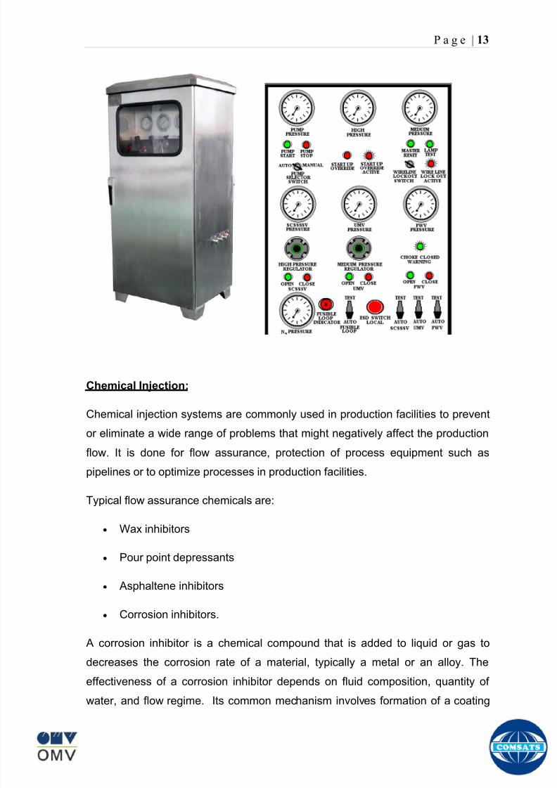
8102019 Gas sweetening Plant
httpslidepdfcomreaderfullgas-sweetening-plant 1762
P a g e | 13
Chemical Injection
Chemical injection systems are commonly used in production facilities to prevent
or eliminate a wide range of problems that might negatively affect the production
flow It is done for flow assurance protection of process equipment such as
pipelines or to optimize processes in production facilities
Typical flow assurance chemicals are
Wax inhibitors
Pour point depressants
Asphaltene inhibitors
Corrosion inhibitors
A corrosion inhibitor is a chemical compound that is added to liquid or gas to
decreases the corrosion rate of a material typically a metal or an alloy The
effectiveness of a corrosion inhibitor depends on fluid composition quantity of
water and flow regime Its common mechanism involves formation of a coating
8102019 Gas sweetening Plant
httpslidepdfcomreaderfullgas-sweetening-plant 1862
P a g e | 14
which prevents access of the corrosive substance to the metal The corrosive
agents are generally oxygen hydrogen sulfide and carbon dioxide
At our production site the major risk is corrosion of piping and equipment The
maximum allowable corrosion rate is approximately 02 mm per year and
corrosion rate without inhibitor could be approximately 11 mm per year so the
corrosion protection program is designed to achieve a target corrosion rate of
less than 01 mm per year which is achieved by an inhibitor system efficiency of
99 Inhibitor is injected into the well stream flow through an atomizing nozzle
located downstream of the respective wellhead coolers at the duplexcarbon steel
interface In normal operation as per NALCO standards chemical (brand name
EC1144B) at rate of frac12 Liter per MMSCFD of gas is being injected into the flow
line of miano15 flow lines made of carbon steel Moreover the composition can
vary depending upon the composition of well fluids and material of pipeline This
method of injection ensures even distribution of the chemical on the interior
surface of the pipeline The individual well sites are equipped with Chemical
Injection Packages comprising of a stainless steel storage tank and two
pneumatic motor driven pumps in parallel Instrument gas is used to drive the
pumps Normally one pump is running with the other standby
Water Conning
Water coning is a term used to describe the mechanism underlying the upward
movement of water into the perforations of a producing well Coning can seriously
impact the well productivity and influence the degree of depletion and the overall
recovery efficiency of the reservoir The specific problems of water coning are
listed below
Costly added water handling
Gas production from the original or secondary gas cap reduces pressure
Reduced efficiency of the depletion mechanism
The water is often corrosive and its disposal costly
The affected well may be abandoned early
Loss of the total field overall recovery
8102019 Gas sweetening Plant
httpslidepdfcomreaderfullgas-sweetening-plant 1962
P a g e | 15
Therefore conning has an important influence on operations recovery and
economics The phenomena is shown in picture below
Corrosion
Corrosion is referred as chemical deterioration of a metal Commonly this
means loss of electrons of metals reacting with water and oxygen
Weakening of iron due to oxidation of the iron atoms is a well-known
example of electrochemical corrosion This is commonly known as
rust Most structural alloys corrode merely from exposure to moisture
in the air but the process can be strongly affected by exposure to
certain substances Corrosion can be concentrated locally to form a pit
or crack or it can extend across a wide area to produce general
deterioration (uniform corrosion)
The following reaction takes place at the active sites
2Fe =gt 2Fe++ + 4e-
The free electrons travel through the metal path to the less active sites where
the following reaction takes place
O2 + 4e- + 2H20 =gt 4 OH-
8102019 Gas sweetening Plant
httpslidepdfcomreaderfullgas-sweetening-plant 2062
P a g e | 16
Recombination of these ions at the active surface produce the following
reaction which yields the iron-corrosion product ferrous hydroxide
2Fe + O2 + 2H2O =gt 2Fe (OH) 2
CORROSION PROTECTION SYSTEM
Coatings and painting
Painting and the application of enamel bitumen and PVC
coating are the most common anti-corrosion treatments They
work by providing a barrier of corrosion-resistant material
between the damaging environment and the structural material
Corrosion Inhibitors
Corrosion inhibitor is injected into the flow lines as mentioned in
detail on page 8
Cathodic Protection
Cathodic Protection (CP) is a technique used to control the corrosion of a
metal surface by making it the cathode of an electrochemical cell It
converts all of the anodic (active) sites on the metal surface to cathodic
(passive) sites by supplying electrical current (or free electrons) from an
alternate source It is accomplished in two ways
a) A simple method of protection connects protected metal to a more easily
corroded sacrificial metal to act as the anode The sacrificial metal then
corrodes instead of the protected metal The process is similar to a simple
DC cell in which the more active metal becomes the anode and corrodes
whereas the less active metal becomes the cathode and is protected
b) For larger structures galvanic anodes cannot economically deliver enough
current to provide protection Therefore impressed current cathodic
protection (ICCP) systems are used These consist of anodes connected
to a DC power source In remote areas power sources such as solar
panels may be used The output DC negative terminal is connected to the
8102019 Gas sweetening Plant
httpslidepdfcomreaderfullgas-sweetening-plant 2162
8102019 Gas sweetening Plant
httpslidepdfcomreaderfullgas-sweetening-plant 2262
P a g e | 18
frequently to limit liquid holdup and minimize the slug volumes of liquid which can
be generated by the system
Coating
Pigs may be used to apply internal pipe coatings such as epoxy coating
materials in operating pipelines Pigs may also be used with corrosion inhibitors
to distribute and coat the entire internal wetted perimeter
Inspection
Pigs are being used more frequently as inspection tools Gauging or sizing pigs
are typically run following the completion of new construction or line repair to
determine if there are any internal obstacles bends or buckles in the pipe Pigs
can also be equipped with cameras to allow viewing of the pipe internals
Electronic intelligent or smart ldquopigsrdquo that use magnetic and ultrasonic systems
have been developed and refined that locate and measure internal and external
corrosion pitting dents buckles and any other anomalies in the pipe wall
Intelligent pigs
The accuracy of location and measurement of anomalies by the intelligent pigs
has continued to improve Initially the electronics and power systems were so
large that intelligent pigs could be used only in lines 30 in and greater in size
The continued sophistication and miniaturization of the electronic systems used
in the intelligent pigs has allowed the development of smaller pigs that can be
used in small-diameter pipelines Newly enacted DOT pipeline-integrity
regulations and rules acknowledge the effectiveness of the intelligent pigs and
incorporate their use in the pipeline-integrity testing process
Compressors
A gas compressor is a mechanical device that increases the pressure of a gas by
reducing its volume Gas pressure is increased by forcing gas molecules together
to reduce gas volume When volume is reduced gas pressure increases
All gases have large spaces among their molecules These spaces could be
enhanced further and decreased by doing some work Work done which is used
8102019 Gas sweetening Plant
httpslidepdfcomreaderfullgas-sweetening-plant 2362
P a g e | 19
for the enhancement of these spaces is called expansion and work done to
minimize these spaces is called compression All gases while expansion
produces cooling effect and while compression of gases raises there
temperature Compression is a term used to force gases to occupy smaller
volumes by increasing their pressure Volume of gases is interlinked with
temperature and pressure of the gas which is cleared by 2 laws govern gas
compressions
Boyles Law
Charles Law
The main types of compressor are listed below
Front End Compressor
The plant currently processes gas from a number of wells The flow and pressure
from some of these wells (currently K-10 K-11 amp K-12) has declined and they
cannot be fed directly into the Central Processing Facility To recover the
maximum gas reserves from these wells a Front End Compressor is employed
The compressor is a two stage double acting gas engine driven reciprocating
(PT) compressor Double acting means that gas is compressed on each end of
the piston It normal operates with a speed range of 600 to 900 RPM and isequipped with four compressor cylinders two for each stage Each cylinder is
8102019 Gas sweetening Plant
httpslidepdfcomreaderfullgas-sweetening-plant 2462
P a g e | 20
also equipped with a variable volume head end pocket
In case of compressor emergency shutdown the production chokes and the
Upper Master Valves on the on line wells will close and operator will be notified in
central control room Sweet gas from gas distribution network is used to operate the
gas engine driver of the compressor package The detailed scheme of working is
shown in figure (page 22 )
PT Reciprocating Compressor
The mechanical cycle of piston tube reciprocating compressor comprises four
strokes the expansion stroke the intake stroke the compression stroke and the
discharge stroke
Expansion Stroke
As the piston moves back on the expansion stroke the chamber volume
increases and the pressure drop As the pressure drops the discharge valve
closes since there is greater pressure in the discharge line than in the chamber
Intake Stroke
As the piston moves back during the intake stroke the pressure decreases until it
is less than the pressure in the inlet line This higher intake pressure opens the
inlet valve and gas rushes into the cylinder equalizing the pressure there with
the intake pressure The compression chamber is now at or near the intake
pressure
Compression Stroke
The piston now starts the compression stroke by moving forward decreasing the
chamber volume and increasing the pressure The increased pressure is now
higher than the intake pressure causing the intake valve to close
Discharge Stroke
The piston continues to move to the left during the discharge stroke This creates
an increase in chamber pressure until it is greater than the discharge pressure
When this happens the Discharge valve opens and the compressed air from the
8102019 Gas sweetening Plant
httpslidepdfcomreaderfullgas-sweetening-plant 2562
P a g e | 21
cylinder goes into the discharge line The compression cycle is then repeated
from the stage
Compressor Capacity
The capacity of the compressor depends upon cylinder displacement That
displacement is simply the volume that the piston displaces (moves) as it travels
from one end of the cylinder to the other Capacity and displacement is equal to
the cross-sectional area of the cylinder times the length of the stroke
Lubrication and Cooling
Lubricating oil is circulated through the system by a gear pump which is chain
driven from the engine crank shaft The oil pump is mounted on the engine front
housing
The pump operates between 30 - 40 psig
8102019 Gas sweetening Plant
httpslidepdfcomreaderfullgas-sweetening-plant 2662
P a g e | 22
A circulating pump deliver cooling water to the water jackets in the cylinder block
flowing around the cylinder liners and is directed into the cylinder heads Each
cylinder head has water cooled exhaust elbows which outlet the water into the
water cooled exhausts From the end of engine the water flows to compressor
1st and 2nd stage cylinders and compressor lube oil cooler (LOwater heat
exchanger) The water from the compressor cylinder and lube oil cooler returns
to engine water cooled exhaust
Figure Flow diagram of Front End Compressor
8102019 Gas sweetening Plant
httpslidepdfcomreaderfullgas-sweetening-plant 2762
P a g e | 23
Centrifugal Compressor
Centrifugal compressors are machines in which velocity and pressure given to air
or gas in a radial direction by one or more impellers diffuser combination In a
centrifugal compressor the mechanical energy is increased by centrifugal action
The gas enters the suction eye of a high speed rotary element called the impeller
which carries radial vanes integrally cast in it As the impeller rotates the blades
of the impeller force the gas outward from the center the impeller to the outer rim
of impeller the increase in velocity of the gas creates a flow pressure area at the
eye of the impeller The gas at the outer rim of the impeller is forced in to a
passage way called a diffuser where the velocity decreases in the pressure of the
gas
Inlet
The inlet to a centrifugal compressor is typically a simple pipe It may include
features such as a valve and both pressure and temperature instrumentation
Centrifugal impeller
The key component that makes a compressor centrifugal is the centrifugal
impeller shown above It is the impellers rotating set of vanes (or blades) that
gradually raises the energy of the working gas This is identical to an axial
compressor with the exception that the gases can reach higher velocities and
energy levels through the impellers increasing radius
8102019 Gas sweetening Plant
httpslidepdfcomreaderfullgas-sweetening-plant 2862
P a g e | 24
Diffuser
The next key component to the simple centrifugal compressor is the diffuser
Downstream of the impeller in the flow path it is the diffusers responsibility to
convert the kinetic energy (high velocity) of the gas into pressure by gradually
slowing (diffusing) the gas velocity
SEPERATORS
A well-stream is a mixture of gases hydrocarbon liquids water solids and
contaminants Due to variations in pressure and temperature gases evolve from
the liquids water vapor condenses and some of the well-stream changes to liquid
and free gas The separation of well-stream fluids takes place in a separator This
pressure vessel is manufactured in three forms
1 horizontal
2 vertical
3 spherical
To help separation the vessel is normally designed with a series of internal
fittings These fittings are built into the separator to ensure total phase separation
of the well-stream
In gas plants separators are given alternative names due to the function they
perform in the process system A scrubber does a similar job to a knockout drum
However the scrubber usually separates a stream containing high gas-to-liquid
ratios The knockout drum is used where a high degree of liquids are entrained in
the gas
Fluid flow from a well can include gas condensable liquid vapors water water
vapor crude oil and solids As well-stream fluids reach ground level where
pressure is lower than in the reservoir the capacity of the liquid to hold gas in
solution decreases and gas separates out of the oil
Separation depends upon the effect of gravity to separate liquids For adequate
separation one fluid must be lighter than the other fluid For example distillates
8102019 Gas sweetening Plant
httpslidepdfcomreaderfullgas-sweetening-plant 2962
P a g e | 25
(gasoline kerosene etc) and crude oil will not separate in a vessel because they
tend to dissolve in each other Because a separator basically depends upon
gravity to separate the fluids the ease with which separation takes place
depends upon the difference in density of the fluids
Droplets of liquid will separate from gas provided
a) The gas remains in the separator long enough
b) The gas flow remains constant to provoke separation
The difference in density between a gas and liquid will therefore determine the
maximum flow rate of liquid in the vessel
Figure Two phase horizontal separator
Gas bubbles in the liquid will break out in some oil field applications in 30 to 60
seconds Consequently the separator is designed so that the liquid remains in
the vessel for 30 to 60 seconds The length of time that a liquid remains in the
vessel is called its residence time Residence time differs widely from field to field
depending upon viscosity and API Gravity
Another important factor which must be considered is temperature Generally a
decrease in operating temperature will increase the liquid recovery in a separator
8102019 Gas sweetening Plant
httpslidepdfcomreaderfullgas-sweetening-plant 3062
P a g e | 26
as the gas condenses By reducing the pressure on the fluid flash separation
occurs resulting in a flow through the separator which is controlled by external
instrumentation
COALESCENCE
Another important principle in fluid separation is that of coalescence This means
the coming together of liquid droplets created by the force of gravity
A common example of coalescing occurs when drops of water form on the
windshield of a car as it is driven in fog As the tiny drops or water which make up
the fog strike the windshield they combine and eventually form a drop large
enough to run down the glass
Several of the internal devices of a separator such as deflector plates
straightening vanes and even the vessel walls are forms of coalescers In each
vessel drops of liquid adhere to the surface of the device and combine with other
8102019 Gas sweetening Plant
httpslidepdfcomreaderfullgas-sweetening-plant 3162
P a g e | 27
drops until the drop is large enough to fall out The effectiveness of separation
will also depend upon the total amount of coalescing surface area that is present
There are many different types of separators used in the Oil amp Gas industry
Consequently separators are manufactured with one two or several internal
fittings depending on their use and quick removal of these fluids from the vessel
DEFLECTOR PLATES
These are fitted in front of the inlet to the separator and can be net or
dish-shaped Their purpose is to absorb the impact of the incoming fluids and to
encourage the separation of gas and liquids They also slow the flow rate of the
liquids through the vessel
WEIRS
A weir is a metal wall which is fitted across the inside of the vessel normally to a
height of 50 of the overall height of the separator Its purpose is to assist the
process of three phase separation The inlet fluids (oil plus water) are given time
to separate in the liquid accumulation section The water level (interface) is
normally controlled at 50 of the height of the weir Oil floating on the wateroverflows the weir and accumulates in the small oil compartment where it is
drawn off under level control
CENTRIFUGAL DEVICES
These are used in both vertical and horizontal separators for gas-liquid
separation The device imparts a swirling motion to the fluids entering the vessel
Centrifugal force causes the heavier liquids to travel outwards towards the walls
of the vessel and the lighter gases to flow up the centre Centrifugal devices are
also known as cyclones
VORTEX BREAKERS
When liquid flows through a drain outlet a vortex (whirlpool) will form This can
be seen when we pull the plug from a sink or bath tub The same would happen
as water and oil flow from the separator This condition a vortex could allow gas
to flow down the centre of the whirlpool and enter the liquid phase causing
8102019 Gas sweetening Plant
httpslidepdfcomreaderfullgas-sweetening-plant 3262
P a g e | 28
pressurizing of tanks etc To stop this happening vortex breakers are fitted to all
liquid outlets Although they come in a number of different designs vortex
breakers all serve the same purpose - to prevent a whirlpool from forming
MIST OR DEMISTER PADS
The gas which is released from the fluids in the separator still contains droplets of
oil and water which coalesce and fall when the drops get large enough The
demister pad assists in this process Made from knitted wire and contained within
a sturdy frame it causes the gas to continually change its direction of flow
Because gas changes direction far easier than liquid the gas will flow around
each strand of wire whilst the liquid entrained in the gas stream will continue and
stick to the wire
COALESCING PLATES
There are several different forms of coalescing devices the most common of
which are coalescing plates These plates are mounted in the flow stream of the
fluids and assist in breaking down oil-water emulsions The fluid is forced to
follow a path that constantly changes direction This causes the water droplets to
gather together or coalesce and fall to the bottom of the separator The same
principle is used to separate gas and oil mixtures when the oil droplets are
induced to coalesce Simply stated every surface within the separator including
the separator walls assists with the coalescing process
STRAIGHTENlNG VANES
These are often fitted to horizontal separators to remove turbulence in the gas
stream after initial separation at the inlet deflector
FLOAT SHEILD
Internal floats are used as level controllers Any agitation of the liquid surface or
the effect of coalesced liquids falling on the float may cause control problems
Therefore a float shield is fitted to enclose the float creating an area of still liquid
8102019 Gas sweetening Plant
httpslidepdfcomreaderfullgas-sweetening-plant 3362
P a g e | 29
MEMBRANES
The gas contains 12 carbon dioxide and 22 ppm of hydrogen sulphide at 115oF
and 1100 psig This needs to be removed before the gas can be exported The
majority of carbon dioxide hydrogen sulphide and water is removed by means of
membranes
Membranes are thin semipermeable barriers that selectively separate some
compounds from others Currently the only commercially workable membranes
used for CO2 removal are polymer based for example cellulose acetate
polyimides polyamides polysulfone polycarbonates and polyetherimide The
membrane does not operate as a filter where small molecules are separated
from larger ones through a medium with pores rather it separates based on how
well different compounds dissolve into the membrane and diffuse through it The
membranes are manufactured in flat sheets consisting of an extremely thin
nonporous layer mounted on a much-thicker and highly porous layer of the same
material providing mechanical strength The flat sheets are combined into a
spiral-wound element (Figure below) Feed gas enters along the side of the
membrane and passes through the feed spacers As the gas travels between
membrane sheets CO2 H2S and H2O permeate through the membrane and are
collected in the permeate tube The driving force for transport is the high-feed
pressure and low-permeate pressures The gas on the feed side that does not
permeate leaves through the side of the element opposite the feed position Once
the membranes have been manufactured into elements six to 12 elements are
joined together and inserted into a tube Multiple tubes are mounted on skids in a
horizontal orientation
8102019 Gas sweetening Plant
httpslidepdfcomreaderfullgas-sweetening-plant 3462
P a g e | 30
Figure Membrane general Working
In high H2S applications most polymers have been shown to have very little
resistance to H2S plasticization (ldquosofteningrdquo of the membrane) and as a
consequence can only be used at very low H2S partial pressure limits Cellulose
acetate membranes in contrast have been shown to be applicable at extreme
H2S partial pressure conditions It is these membranes that have been utilized in
the testing to determine the limits of membrane performance in high H 2S
applications
The primary membranes used in Kadanwari facility are Cellulose acetate
Cellulose acetic acid and acetic anhydride are mixed together and reacted to
form cellulose acetate polymers This process is aided by the addition of a small
amount of sulfuric acid which is subsequently neutralized during processing
However the membranes are bought from UOP (vendor) and installed for use
8102019 Gas sweetening Plant
httpslidepdfcomreaderfullgas-sweetening-plant 3562
P a g e | 31
How membrane work
The basic principle of separation is selectivity of certain components of a mixture
for the membrane For example the cellulose acetate membrane has very high
selectivity for CO2 and H2S as compared to CH4 Therefore such type of
membrane can be used in gas sweetening process
The selectivity is directly related to the Permeability of gas which accounts that
which gas can pass across the membrane more easily In simple words
membranes being polymer materials are made of long chains of molecules The
different structure of polymer materials only allow selective molecules to pass
through them depending upon chemical and physical compatibility Thus
permeability depends upon choice of polymer
The permeability is determined by permeability coefficient (P) and is product of
solubility (S) and diffusivity (D)
P = S D
Solubility
The solubility is mainly determined by ease of condensation Heavy molecules
are more readily condensed Therefore higher molecular weighted molecules will
more easily condensed and therefore have greater solubility
Molecule Molecular weight
CH4 16
H2S 34
CO2 44
8102019 Gas sweetening Plant
httpslidepdfcomreaderfullgas-sweetening-plant 3662
P a g e | 32
Diffusivity
Diffusivity is ease of molecule to penetrate into some material It depends on size
of gas molecule Here size of molecule is not to be confused by molecular weight
it is the size of the structure Eg the size of O2 molecule is smaller than N2
Molecule Molecular Diameter (Ao)
CO2 33
H2S 36
Ch4 40
For cellulose acetate
DCO2DCH4 S CO2S CH4 P CO2P CH4
45 73 308
Chemical degradation
Cellulose acetate polymer is chemically degraded by a process called hydrolysis
which means breaking apart by the addition of water This is a chemical reaction
in which water is added to the cellulose acetate polymer causing the release of
acetic acid molecules This process proceeds stepwise until all the acetate
groups are released resulting in the reformation of cellulose Moreover alcohols
aromatic hydrocarbons or solvents with chlorine nitro benzene or similar
aromatic solvents will harm the membrane It will expand and lose plastification in
contact with them
Effect of Temperature
The permeation rates of all gases increases with increasing temperature
however membrane selectivity for CO2 over hydrocarbon decreases at higher
8102019 Gas sweetening Plant
httpslidepdfcomreaderfullgas-sweetening-plant 3762
P a g e | 33
temperature Consequently CO2 removal will improve as operating temperature
increases but hydro carbon recovery will decrease
Primary Membrane
The primary membranes comprise of two trains Each train consists of two
sections AB and CD each section consists of a 30 tube membrane skid (A and
C) followed by a 25 tube skid (B and D) The conditioned gas (after pre-
treatment) enters the primary membrane via the particulate filter adjacent to the
skid The gas is fed to the membranes through a common inlet manifold which
supplies primary membranes skids A and C A pressure control loop located
upstream of the manual inlet isolation valve is provided to maintain a constant
supply pressure to the membrane skid and to allow for preheating at the inlet
prior to skid start-up This pressure control loop can also be used during start-up
to control the pressurization of the pretreatment skid and associated pipes to the
primary membranes
The gas passes through membrane skid A the residual gas exiting the membrane
skid is sent to skid B and the permeate to common permeate discharge header An
identical arrangement is provide on the inlet to skid C as provided on skid A Theresidual gas from skid B combines with the residual gas from skid D in a common
discharge header and is then sent to the H2S polishing towers via the feed coolers
on the pre-treatment skid The permeate from skid B is sent to the common
permeate discharge header The permeate discharge header sends the gas to
either the recycle compressor or the vent header via a pressure control loop
Overpressure protection for the membranes is provided by a pressure safety valve
on the supply header to the membrane banks
8102019 Gas sweetening Plant
httpslidepdfcomreaderfullgas-sweetening-plant 3862
P a g e | 34
Secondary (Recycle) Membrane
The recycle membranes comprise of a single train with two skids each with four
banks of membrane tubes The conditioned gas from the discharge of the recycle
pre-treatment skid is routed to the first recycle membrane skid The gas passes
through the membranes the residual gas is fed to primary membrane (skid A) inlet
via feed gas cooler and permeate to the common permeate discharge header An
identical arrangement is provide on the inlet to skid B Permeate from the recycle
membrane skids A and B is routed to the vent header Some portion of permeate is
heated and sent for regeneration in Mem-Guard units Nitrogen purge can be
connected downstream of the inlet isolation valve on each skid to enable the
membrane tubes to be purged and left pressurized during prolonged shutdown
8102019 Gas sweetening Plant
httpslidepdfcomreaderfullgas-sweetening-plant 3962
P a g e | 35
Figure Flow Diagram of Recycle membrane unit
8102019 Gas sweetening Plant
httpslidepdfcomreaderfullgas-sweetening-plant 4062
P a g e | 36
ADVANTAGES OF MEMBRANE SYSTEMS
Membrane systems have major advantages over more-traditional methods of
acid gas removal
Lower capital cost Membrane systems are skid mounted and so the
scope cost and time taken for site preparation are minimal Installation
costs are significantly lower than alternative technologies especially for
remote areas Furthermore no additional facilities for solvent storage and
water treatment needed by other processes are required
Lower operating costs The only major operating cost for single-stage
membrane systems is membrane replacement This cost is significantly
lower than the solvent replacement and energy costs associated with
traditional technologies The improvements in membrane and
pretreatment design allow a longer useful membrane life which further
reduces operating costs The energy costs of multistage systems with
large recycle compressors are usually comparable to those for traditionaltechnologies
Deferred capital investment Often contracted sales-gas flow rates
increase over time as more wells are brought on-line With traditional
technologies the system design needs to take this later production into
account immediately and so the majority of the equipment is installed
before it is even needed The modular nature of membrane systems
means that only the membranes that are needed at start-up need be
installed The rest can be added either into existing tubes or in new skids
only when they are required
Operational simplicity and high reliability Because single-stage
membrane systems have no moving parts they have almost no
8102019 Gas sweetening Plant
httpslidepdfcomreaderfullgas-sweetening-plant 4162
P a g e | 37
unscheduled downtime and are extremely simple to operate They can
operate unattended for long periods of time The addition of a recycle
compressor adds some complexity to the system but still much less than
with a solvent- or adsorbent-based technology Multistage systems can be
operated at full capacity as single-stage systems when the recycle
compressor is down
Good weight and space efficiency Skid construction can be optimized
to the space available This space efficiency is especially important for
offshore environments where deck area is at a premium and is the
reason why so many new offshore developments have chosen to use
membranes for acid gas removal Figure 6 illustrates the space efficiency
of membrane systems The membrane unit in the lower left corner
replaced all the amine and glycol plant equipment shown in the rest of the
picture
Adaptability Because membrane area is dictated by the percentage of
acid gas removal rather than absolute acid gas removal small variations
in feed acid gas content hardly change the sales-gas acid gas
specification For example a system designed for 10 down to 3 acid
gas removal produces a 35 product from a 12 feed gas and a 5
product from a 15 feed gas
Design efficiency The membrane and pretreatment systems integrate a
number of operations such as dehydration CO2 and H2S removal dew-
point control and mercury removal Traditional acid gas removal
technologies require all of these operations as separate processes and
may also require additional dehydration because some technologies
saturate the product stream with water
8102019 Gas sweetening Plant
httpslidepdfcomreaderfullgas-sweetening-plant 4262
P a g e | 38
Power generation The permeate gas from membrane systems can be
used to provide fuel gas for power generation either for a recycle
compressor or other equipment
Ideal for debottlenecking Because expanding solvent- or adsorbent-
based acid gas removal plants without adding additional trains is difficult
an ideal solution is to use membranes for bulk acid gas removal and leave
the existing plant for final cleanup An additional advantage is that the
permeate gas from the membrane system can often be used as fuel for
the existing plant thus avoiding significant increase in hydrocarbon
losses
Environmentally friendly Membrane systems do not involve the
periodic removal and handling of spent solvents or adsorbents Permeate
gases can be flared used as fuel or re-injected into the well Items thatdo need disposal such as spent membrane elements can be incinerated
Ideal for remote locations Many of the factors mentioned above make
membrane systems a highly desirable technology for remote locations
where spare parts are rare and labor unskilled Furthermore solvents
storage and trucking water supply power generation or extensive
infrastructure are not required
Re-injection optimizations Since the permeate stream from the
membrane system can be operated at elevated pressures it is possible to
further pressurize by re-injection compression train
8102019 Gas sweetening Plant
httpslidepdfcomreaderfullgas-sweetening-plant 4362
P a g e | 39
Sorption
Sorption is a physical and chemical process by which one substance becomes
attached to another
It is of two main types
1 Absorption
2 Adsorption
Absorption
Absorption is a physical or chemical phenomenon or process in which atoms
molecules or ions enter some bulk phase ndash gas liquid or solid material This is a
different process from adsorption since molecules undergoing absorption are
taken up by the volume not by the surface (as in the case for adsorption)
Absorption process may be chemical (reactive) or physical (non-reactive)
Physical absorption
Physical absorption or non-reactive absorption is made between two phases ofmatter a liquid absorbs a gas or a solid absorbs a liquid
When a liquid solvent absorbs a gas mixture or part of it a mass of gas moves
into the liquid For example water may absorb oxygen from the air This mass
transfer takes place at the interface between the liquid and the gas at a rate
depending on both the gas and the liquid This type of absorption depends on the
solubility of gases the pressure and the temperature The rate and amount of
absorption also depend on the surface area of the interface and its duration in
time
When a solid absorbs a liquid mixture or part of it a mass of liquid moves into the
solid For example a clay pot used to store water may absorb some of the water
This mass transfer takes place at the interface between the solid and the liquid
at a rate depending on both the solid and the liquid
8102019 Gas sweetening Plant
httpslidepdfcomreaderfullgas-sweetening-plant 4462
P a g e | 40
Chemical absorption
Chemical absorption or reactive absorption is a chemical reaction between the
absorbed and the absorbing substances Sometimes it combines with physical
absorption This type of absorption depends upon the stoichiometry of the
reaction and the concentration of its reactants
Adsorption
Adsorption is the adhesion of atoms ions or molecules from a gas liquid or
dissolved solid to a surface This process creates a film of the adsorbate on the
surface of the adsorbent The binding to the surface is usually weak and
reversible Compounds with color and those that have taste or odor tend to bind
strongly Compounds that vibrate at frequencies in the visible spectrum are very
often are strongly adsorbed on activated carbon
The most common industrial adsorbents are activated carbon silica gel and
alumina because they present enormous surface areas per unit weight
Depending on the nature of attractive forces existing between the adsorbate and
adsorbent adsorption can be classified as
i) Physical adsorption
ii) Chemical adsorption
i) Physical adsorption (Physisorption)
In physical adsorption the forces of attraction between the molecules of the
adsorbate and the adsorbent are of the weak van der Waals type Since the
forces of attraction are weak the process of physisorption can be easily reversed
by heating or decreasing the pressure of the adsorbate (as in the case of gases)
8102019 Gas sweetening Plant
httpslidepdfcomreaderfullgas-sweetening-plant 4562
P a g e | 41
ii) Chemical adsorption (Chemisorption)
In chemisorption the forces of attraction between the adsorbate and the
adsorbent are very strong the molecules of adsorbate form chemical bonds with
the molecules of the adsorbent present in the surface
Adsorption is generally accompanied by release of energy that is most
adsorption processes are exothermic in nature Adsorption is a spontaneous
process therefore its free energy change is negative (∆Glt0) However the
entropy change associated with adsorption is generally negative because the
adsorbate molecules lose their translation freedom when they get attached to the
surface of the adsorbent Therefore in order for ∆G to be negative the enthalpy
change (∆H) must be sufficiently negative such that (∆G=∆H-T∆S) lt 0 This
explanation accounts for exothermic adsorption processes In cases where
endothermic adsorption occurs the entropy change ∆S is sufficiently positive
such that ∆G remains negative
Pre treatment
The main function of pretreatment skid is to provide membrane inlet specification
gas as mentioned by the vendor UOP It removes the contaminants that would
poison the membranes like dust solids (adsorbent particles) lube oil heavy
hydrocarbons etc It consists of
Feed Cooler
Feed Gas Scrubber
Filter Coalescer
Feed Gas Heater
Activated Carbon Guard Filter
Particle Filter
8102019 Gas sweetening Plant
httpslidepdfcomreaderfullgas-sweetening-plant 4662
8102019 Gas sweetening Plant
httpslidepdfcomreaderfullgas-sweetening-plant 4762
P a g e | 43
The regeneration is carried out by heated permeate gas from the recycle
membranes at 450oF The vessel is depressurized to 20 psi and heated gas is
introduced from top The gas carries out the adsorbed contaminants and leaves
the vessel from bottom cleaning the adsorbent This contaminated gas is burnt in
the flare
UOP the vendor of Memguard unit has never disclosed that what substance
MG3 and MG5 exactly are But as mentioned by vendor that both care class of
aluminosilicates Therefore MG3 can be potassium aluminosilicate and MG5 can
be Calcium aluminosilicate These are molecular sieves adsorbents Molecular
sieves are a microporous material which can selectively adsorb gases andliquids They are synthetic zeolites (crystalline metal aluminosilicates) which
upon dehydration can efficiently and selectively remove water or other
solvents The selectivity of a molecular sieve is determined by its pore size
molecules with a critical diameter which is less than the pore size will be
efficiently adsorbed while larger molecules will be excluded
8102019 Gas sweetening Plant
httpslidepdfcomreaderfullgas-sweetening-plant 4862
P a g e | 44
3A Molecular Sieve Adsorbent
The 3A molecular sieve adsorbent has a 3 angstrom (3A) pore size which means
that any molecule that is larger than the 3 angstrom pores will not be adsorbed
The 3A molecular sieve is the potassium type of A crystalline structure and is a
form of alkali Aluminosilicate For a 3A molecular sieve the sequence rate that
adsorption occurs is He Ne N and H2O
Due to the crystalline structure molecular sieves that have a 3 angstrom pore
size have a very high rate of adsorption and properties that promote a longer life
for products treated by the sieve The most common use for the 3A molecular
sieve is to remove water and moisture from materials that are in gas and liquid
form
5A Molecular Sieve Adsorbent
These are molecular sieve adsorbents with a pore size of 5 angstrom (5A) 5A
molecular sieves are unable to adsorb any molecules or impurities that are
smaller than 5A It is calcium form of type A crystalline structure and is form of analkali-aluminosilicate that is most commonly used to separate isomerous alkanes
from normal alkanes and to co-adsorb moisture and water along with carbon
dioxide from gases In additional 5A molecular sieves are used for gaseous
pressure swing adsorption (PSA)mdashthat is to separate particular gases from other
gases
Adsorption of nC4H10
Adsorption of nC4H10
Adsorption of C3H8 to C22H46
Adsorption of Freon-12 (dichlorodifluoromethane)
Natural gas drying
Normal- and iso-paraffin separation
Separation of aromatic
8102019 Gas sweetening Plant
httpslidepdfcomreaderfullgas-sweetening-plant 4962
P a g e | 45
Inlet Composition of Memguard vessel
COMPSOSITION MOLE
CARBON DIOXIDE 1096
MEHTANE 8593
ETHANE 173
PROPANE 023
I-BUTANE 008
N BUTANE 004
PENTANES 004
HEXANE + 000
NITROGEN 076
WATER 007
Outlet Composition of Memguard vessel
COMPSOSITION MOLE
CARBON DIOXIDE 1098
MEHTANE 8608
ETHANE 173
PROPANE 023
I-BUTANE 008N BUTANE 004
PENTANES 004
HEXANE + 000
NITROGENT 076
WATER 000
H2S polisher
The H2S polishing unit has been designed to treat 187 MMscfday of natural gas
containing up to 11 CO2 and 21 ppm H2S where the level of the CO2 and H2S
is reduced using a MemGuard Membrane separation unit The unit is situated
down-stream of the membrane unit and will further reduce the level of H2S in the
processed gas to a sales gas specification of 38 ppm
8102019 Gas sweetening Plant
httpslidepdfcomreaderfullgas-sweetening-plant 5062
P a g e | 46
This process uses three non-regenerable fixed bed absorber vessels using a low
temperature high activity absorbent The absorbent is a mixture of activated
metal oxides (mainly zinc oxide) The three towers can are generally operated in
parallel arrangement but on demand can be used in series (any of alternate
arrangements of A B C vessels) as shown in figure
The higher sales gas flow rate increased the catalyst consumption and
replacement frequency
ZnO + H2S =gt ZnS + H20
Routine samples are taken from the beds to provide a check on each bed
performance and to follow the saturation profile during the absorbent life After
the adsorbent has been fully utilized the adsorption vessels are recharged with
new adsorbent discarding the utilized one in a safe manner
109oF
1215 psig
Before H2S Polishing After H2S Polishing
8102019 Gas sweetening Plant
httpslidepdfcomreaderfullgas-sweetening-plant 5162
P a g e | 47
Figure
H2S Tower
Inlet pipe
4 Drums of 19mm
ceramic Balls
6 Micron mesh
5 Drums of 50mmceramic
1 Drums of19mm ceramic
01 Drums of6mm ceramic
112 drums of
Catalist ZnO
8102019 Gas sweetening Plant
httpslidepdfcomreaderfullgas-sweetening-plant 5262
P a g e | 48
Recycle Compressor
The permeate gas of the primary membrane unit carries recoverable amount of
CH4 It is fed to recycle membrane unit for further CH 4 recovery But the
permeate pressure from primary membranes which has been reduced to 12 psi
must be regenerated to 1200 psi for the gas to be fed again to the system For
this purpose we have employed recycle compressor The compressor is a four
stage centrifugal compressor It is driven by gas turbine of 31200 HP It has 25
MW producing capacity
Figure Recycle Compressor Process Flow Diagram
8102019 Gas sweetening Plant
httpslidepdfcomreaderfullgas-sweetening-plant 5362
P a g e | 49
Sales Gas Compressor
Gas from H2S polishing unit is sent to sales gas compressor where its pressure
is enhanced to 1100 psi so it may be injected to SNGPL high pressure trunk line
Sales gas compressor is single stage gas turbine driven
Figure Process Flow of Sales Gas Compressor
8102019 Gas sweetening Plant
httpslidepdfcomreaderfullgas-sweetening-plant 5462
P a g e | 50
Cooling Towers
A cooling tower is a heat rejection device which extracts waste heat to theatmosphere through the cooling of a water stream to a lower temperature Hot
water from the system enters the cooling tower and is distributed over the fill
(heat transfer surface) Air is induced or forced through the fill causing a small
portion of the water to evaporate This evaporation removes heat from the
remaining water which is collected in the cold water basin and returned to the
system to absorb more heat Each cooling tower line although operating under
the same basic principle of operation is arranged a little differently
Types
Natural draft mdash Utilizes buoyancy via a tall chimney Warm moist air naturally
rises due to the density differential compared to the dry cooler outside air Warm
moist air is less dense than drier air at the same pressure This moist air
buoyancy produces an upwards current of air through the tower
Mechanical draft mdash Uses power-driven fan motors to force or draw airthrough the tower
o Induced draft mdash A mechanical draft tower with a fan at the
discharge (at the top) which pulls air up through the tower The fan
induces hot moist air out the discharge This produces low entering
and high exiting air velocities reducing the possibility of
recirculation in which discharged air flows back into the air intake
o Forced draft mdash A mechanical draft tower with a blower type fan at
the intake The fan forces air into the tower creating high entering
and low exiting air velocities The low exiting velocity is much more
susceptible to recirculation This fanfill geometry is also known as
blow-through
8102019 Gas sweetening Plant
httpslidepdfcomreaderfullgas-sweetening-plant 5562
P a g e | 51
Forced Draft Cooling Tower Vs Induced Draft Cooling Tower
Induced Draft Cooling Tower have the ability to handle large water flow
rate than Forced Draft Cooling Tower
Induced Draft Cooling Tower is suitable for large cell sizes and fan sizes
as compared with Forced Draft Larger fan size may result in greater
efficiency and consequently lower power and sound level
Forced Draft Cooling Tower can be square or rectangular type only
however Induced Draft Cooling Towers can be round square or
rectangular type
Induced Draft Cooling Tower uses more compact ground area than Forced
Draft Cooling Tower equivalent capacity due to absence of fan on one
side
Fan equipment is warm exhaust air is less liable to icing up in winter
operation (Cold Countries)
Higher velocity in Forced Draft Cooling Tower cause drop in suspension
and cause additional static resistance to system
Configuration
There are two main configurations of factory assembled cooling towers crossflow
and counterflow In crossflow cooling towers the water flows vertically down the
fill as air flows horizontally across In counterflow cooling towers the water flows
vertically down the fill as air flows vertically up
Crossflow Configuration Counterflow Configuration
8102019 Gas sweetening Plant
httpslidepdfcomreaderfullgas-sweetening-plant 5662
P a g e | 52
Drift mdash Water droplets that are carried out of the cooling tower with the exhaust
air Drift droplets have the same concentration of impurities as the water entering
the tower The drift rate is typically reduced by employing baffle-like devices
called drift eliminators through which the air must travel after leaving the fill and
spray zones of the tower
Blow-out mdash Water droplets blown out of the cooling tower by wind generally at
the air inlet openings Water may also be lost in the absence of wind through
splashing or misting Devices such as wind screens louvers splash deflectors
and water diverters are used to limit these losses
Blow-down mdash The portion of the circulating water flow that is removed (usually
discharged to a drain) in order to maintain the amount of Total Dissolved Solids
(TDS) and other impurities at an acceptably low level Higher TDS concentration
in solution may result from greater cooling tower efficiency However the higher
the TDS concentration the greater the risk of scale biological growth and
corrosion
Make-up mdash The water that must be added to the circulating water system in
order to compensate for water losses such as evaporation drift loss blow-out
blow-down etc
Approach mdash The approach is the difference in temperature between the cooled-
water temperature and the entering-air wet bulb temperature
Range mdash The range is the temperature difference between the warm water inlet
and cooled water exit
Fill mdash Inside the tower fills are added to increase contact surface as well as
contact time between air and water to provide better heat transfer The efficiency
of the tower depends on the selection and amount of fill
8102019 Gas sweetening Plant
httpslidepdfcomreaderfullgas-sweetening-plant 5762
P a g e | 53
There are two types of fills that may be used
o Film type fill (causes water to spread into a thin film)
o Splash type fill (breaks up falling stream of water and interrupts its
vertical progress)
Important
Scale build up is controlled by adding chemicals to the cooling loop and diluting
the concentration by blow down and make-up Following chemicals are added to
the Cooling to control CorrosionSale and microbial growth
Corrosion Inhibitor To control corrosion in the Cooling system
Dispersant To kept ions in suspension to avoid settle down and buildup
Sodium hypo Chlorite To Control microbial Growth
Acid To control Alkalinity in the system
High Stress Polymer To run the system at higher conductivity It is a
multifunctional polymer for Zinc amp Phosphate stabilization in cooling tower
Fin Fan Cooler
Fin fan heat exchanger is simply a pressure vessel which cools a circulating fluid
within finned tubes by forcing ambient air over the exterior of the tubes A
common example of an air cooler is a carrsquos radiator Fin Fan Coolers are used in
any application where large quantities of heat need to be transferred This
includes chemical and petrochemical industries power stations waste-to-energy
facilities as well as steelworks
Fin Fan Cooler are used for two primary reasons
They increase plant efficiency
They are a green solution as compared to cooling towers and shell and
tube heat exchangers because they do not require an auxiliary water
8102019 Gas sweetening Plant
httpslidepdfcomreaderfullgas-sweetening-plant 5862
P a g e | 54
supply (water lost due to drift and evaporation plus no water treatment
chemicals are required)
Figure General Overview of Fin Fan Cooler
Produced Water
The produced water system receives liquid from the equipment Miano slug
catcher train 1 and 2 inlet separators and is fed to three phase separator where
water oil and gas is separated The gases produced are burnt in incinerator
whereas hydrocarbon liquid is stored to be sold Liquid from compressors
recycle inlet separator recycle feed scrubber high and low pressure slug
catchers is passed to degasser Separated water is injected down the earth
Incinerator
The term incinerate means to burn something until nothing is left but ashes An
incinerator is a unit or facility used to burn trash and other types of waste until it is
reduced to ash An incinerator is constructed of heavy well-insulated materials
so that it does not give off extreme amounts of external heat The high levels of
heat are kept inside the furnace or unit so that the waste is burned quickly and
efficiently If the heat were allowed to escape the waste would not burn as
completely or as rapidly
8102019 Gas sweetening Plant
httpslidepdfcomreaderfullgas-sweetening-plant 5962
P a g e | 55
Control System
The plant is controlled at CCR (Central Control Room) by PLCs (Programmable
Logic Controllers) through fiber optic control line All control parameters are
received at LER (Local Equipment Room) via two optic fiber control lines One
being primary and other secondary operating in redundancy ie if primary fails
control shifts to secondary These control parameters are sent to CCR via single
optic fiber cable
Safety System
Wellheads and Gas Processing Plant have their own Fire amp Gas detection
systems emergency shutdown (ESD) Plant has a fault tolerant controller It is
based on Triple Modular Redundant (TMR) architecture manufactured by
Triconex The TMR system is based on three isolated parallel control systems
integrated into one system The system operates on a two out of three voting
principle which provides high integrity error free uninterrupted operation with no
single point of failure The TMR receives inputs from Process Sensors Manual
Switches Fire amp Gas Detectors Packaged Equipment Control Systems and
Product Exporting Facilities The TMR carries out cause and effect processing on
the data received and where necessary produces output signals Outputs from
the TMR are hard wired directly to ESD shutdown and blow down valve
solenoids motor control instrumentelectrical interfaces to control electrical
drives package equipment logic control systems manifold area as well as
telecoms
The operator in central control room is able to accept alarms and once the fault
has been cleared reset the input All the control systems are centralized to a
single interface All the PLCs (Programmable Logic Controllers) communicate with
the servers and servers communicate with the clients through Ethernet connectivity
Centralization eases the navigation of different systems at a common interface
Emergency Shutdown
The ESD system receives inputs from field mounted instrumentation on the process
8102019 Gas sweetening Plant
httpslidepdfcomreaderfullgas-sweetening-plant 6062
P a g e | 56
and utility equipment and initiates executive actions appropriate to the level of ESD
The system is an Active system which is in standby and will activate when in an
alarm or fault condition The Kadanwari Gas Process Facility ESD system is
comprised of five (5) levels The emergency severity decreases with increasing ESD
level number
ESD 1
This shutdown level is automatically initiated by fire major gas leak or a detected
toxic atmosphere in the process area of the plant or manually from CCR A level 1
shutdown will cause all production to cease close all emergency shutdown
valves stop the process and shutdown of the main power generation The
emergency vent valves to the stack will open and in addition all equipment of zone 1
certified will be isolated This is the highest level of ESD and will cause the following
to occur
All Shutdown Valves (SDVs) on the process facility will close All slowdown Valves (BDVs) on the process facility will open
All Main Gas Driven Generators will be tripped
Emergency Diesel Generator will start
All electrical power to process and utility rotating equipment will be
isolated
Wellhead Choke Valves Close Wing Valves Close Upper Master Valve
(UMV) Close
ESD 2
This shutdown level is activated automatically if a major process or utility failure
occurs or manually from CCR All production to the plant from the wellhead is
stopped All emergency shutdown valves trip to their fail safe position
Venting shall be as specified This level of ESD will cause the following to occur
8102019 Gas sweetening Plant
httpslidepdfcomreaderfullgas-sweetening-plant 6162
P a g e | 57
All Shutdown Valves (SDVs) on the process facility will close
All electrical power to process and utility rotating equipment will be
isolated
Wellhead Choke Valve Close Wing Valves Close and Upper Master Valve(UMV) Close
ESD 3
The level 3 shutdown isolates and stops a single process train only Production
continues via the other train This ESD level is initiated by process conditions or
operator at local panel This level of ESD will cause the following to occur
ESD 3A Train 1 production to cease
ESD 3B Train 2 production to cease
All online wellhead choke valves go to minimum flow ie (1O )
ESD 4
A level 4 shutdown shall cease all production from an entire field either
Kadanwari or Miano upstream of the associated slug catchers ESD 4K for
Kadanwari amp ESD 4M for Miano This ESD level is initiated automatically by slug
catcher abnormal process conditions This level of ESD will cause the following
to occur
All SDVs close isolating the relevant slug catcher and its upstream gas
production facility from the Kadanwari Gas Processing Plant
All Wellhead Choke Valves Close Wing Valves Close and Upper MasterValves (UMV) of the relevant gas production facility Close
A parallel timer is provided to close within 10 second if not closed in given
time SSSV seals the well
ESD 5
A level 5 shutdown represents equipment shutdown for the protection of the
individual equipment without any change in the process This level of ESD is for the
protection of various pieces of equipment and is initiated by its own inputs eg
8102019 Gas sweetening Plant
httpslidepdfcomreaderfullgas-sweetening-plant 6262
8102019 Gas sweetening Plant
httpslidepdfcomreaderfullgas-sweetening-plant 1862
P a g e | 14
which prevents access of the corrosive substance to the metal The corrosive
agents are generally oxygen hydrogen sulfide and carbon dioxide
At our production site the major risk is corrosion of piping and equipment The
maximum allowable corrosion rate is approximately 02 mm per year and
corrosion rate without inhibitor could be approximately 11 mm per year so the
corrosion protection program is designed to achieve a target corrosion rate of
less than 01 mm per year which is achieved by an inhibitor system efficiency of
99 Inhibitor is injected into the well stream flow through an atomizing nozzle
located downstream of the respective wellhead coolers at the duplexcarbon steel
interface In normal operation as per NALCO standards chemical (brand name
EC1144B) at rate of frac12 Liter per MMSCFD of gas is being injected into the flow
line of miano15 flow lines made of carbon steel Moreover the composition can
vary depending upon the composition of well fluids and material of pipeline This
method of injection ensures even distribution of the chemical on the interior
surface of the pipeline The individual well sites are equipped with Chemical
Injection Packages comprising of a stainless steel storage tank and two
pneumatic motor driven pumps in parallel Instrument gas is used to drive the
pumps Normally one pump is running with the other standby
Water Conning
Water coning is a term used to describe the mechanism underlying the upward
movement of water into the perforations of a producing well Coning can seriously
impact the well productivity and influence the degree of depletion and the overall
recovery efficiency of the reservoir The specific problems of water coning are
listed below
Costly added water handling
Gas production from the original or secondary gas cap reduces pressure
Reduced efficiency of the depletion mechanism
The water is often corrosive and its disposal costly
The affected well may be abandoned early
Loss of the total field overall recovery
8102019 Gas sweetening Plant
httpslidepdfcomreaderfullgas-sweetening-plant 1962
P a g e | 15
Therefore conning has an important influence on operations recovery and
economics The phenomena is shown in picture below
Corrosion
Corrosion is referred as chemical deterioration of a metal Commonly this
means loss of electrons of metals reacting with water and oxygen
Weakening of iron due to oxidation of the iron atoms is a well-known
example of electrochemical corrosion This is commonly known as
rust Most structural alloys corrode merely from exposure to moisture
in the air but the process can be strongly affected by exposure to
certain substances Corrosion can be concentrated locally to form a pit
or crack or it can extend across a wide area to produce general
deterioration (uniform corrosion)
The following reaction takes place at the active sites
2Fe =gt 2Fe++ + 4e-
The free electrons travel through the metal path to the less active sites where
the following reaction takes place
O2 + 4e- + 2H20 =gt 4 OH-
8102019 Gas sweetening Plant
httpslidepdfcomreaderfullgas-sweetening-plant 2062
P a g e | 16
Recombination of these ions at the active surface produce the following
reaction which yields the iron-corrosion product ferrous hydroxide
2Fe + O2 + 2H2O =gt 2Fe (OH) 2
CORROSION PROTECTION SYSTEM
Coatings and painting
Painting and the application of enamel bitumen and PVC
coating are the most common anti-corrosion treatments They
work by providing a barrier of corrosion-resistant material
between the damaging environment and the structural material
Corrosion Inhibitors
Corrosion inhibitor is injected into the flow lines as mentioned in
detail on page 8
Cathodic Protection
Cathodic Protection (CP) is a technique used to control the corrosion of a
metal surface by making it the cathode of an electrochemical cell It
converts all of the anodic (active) sites on the metal surface to cathodic
(passive) sites by supplying electrical current (or free electrons) from an
alternate source It is accomplished in two ways
a) A simple method of protection connects protected metal to a more easily
corroded sacrificial metal to act as the anode The sacrificial metal then
corrodes instead of the protected metal The process is similar to a simple
DC cell in which the more active metal becomes the anode and corrodes
whereas the less active metal becomes the cathode and is protected
b) For larger structures galvanic anodes cannot economically deliver enough
current to provide protection Therefore impressed current cathodic
protection (ICCP) systems are used These consist of anodes connected
to a DC power source In remote areas power sources such as solar
panels may be used The output DC negative terminal is connected to the
8102019 Gas sweetening Plant
httpslidepdfcomreaderfullgas-sweetening-plant 2162
8102019 Gas sweetening Plant
httpslidepdfcomreaderfullgas-sweetening-plant 2262
P a g e | 18
frequently to limit liquid holdup and minimize the slug volumes of liquid which can
be generated by the system
Coating
Pigs may be used to apply internal pipe coatings such as epoxy coating
materials in operating pipelines Pigs may also be used with corrosion inhibitors
to distribute and coat the entire internal wetted perimeter
Inspection
Pigs are being used more frequently as inspection tools Gauging or sizing pigs
are typically run following the completion of new construction or line repair to
determine if there are any internal obstacles bends or buckles in the pipe Pigs
can also be equipped with cameras to allow viewing of the pipe internals
Electronic intelligent or smart ldquopigsrdquo that use magnetic and ultrasonic systems
have been developed and refined that locate and measure internal and external
corrosion pitting dents buckles and any other anomalies in the pipe wall
Intelligent pigs
The accuracy of location and measurement of anomalies by the intelligent pigs
has continued to improve Initially the electronics and power systems were so
large that intelligent pigs could be used only in lines 30 in and greater in size
The continued sophistication and miniaturization of the electronic systems used
in the intelligent pigs has allowed the development of smaller pigs that can be
used in small-diameter pipelines Newly enacted DOT pipeline-integrity
regulations and rules acknowledge the effectiveness of the intelligent pigs and
incorporate their use in the pipeline-integrity testing process
Compressors
A gas compressor is a mechanical device that increases the pressure of a gas by
reducing its volume Gas pressure is increased by forcing gas molecules together
to reduce gas volume When volume is reduced gas pressure increases
All gases have large spaces among their molecules These spaces could be
enhanced further and decreased by doing some work Work done which is used
8102019 Gas sweetening Plant
httpslidepdfcomreaderfullgas-sweetening-plant 2362
P a g e | 19
for the enhancement of these spaces is called expansion and work done to
minimize these spaces is called compression All gases while expansion
produces cooling effect and while compression of gases raises there
temperature Compression is a term used to force gases to occupy smaller
volumes by increasing their pressure Volume of gases is interlinked with
temperature and pressure of the gas which is cleared by 2 laws govern gas
compressions
Boyles Law
Charles Law
The main types of compressor are listed below
Front End Compressor
The plant currently processes gas from a number of wells The flow and pressure
from some of these wells (currently K-10 K-11 amp K-12) has declined and they
cannot be fed directly into the Central Processing Facility To recover the
maximum gas reserves from these wells a Front End Compressor is employed
The compressor is a two stage double acting gas engine driven reciprocating
(PT) compressor Double acting means that gas is compressed on each end of
the piston It normal operates with a speed range of 600 to 900 RPM and isequipped with four compressor cylinders two for each stage Each cylinder is
8102019 Gas sweetening Plant
httpslidepdfcomreaderfullgas-sweetening-plant 2462
P a g e | 20
also equipped with a variable volume head end pocket
In case of compressor emergency shutdown the production chokes and the
Upper Master Valves on the on line wells will close and operator will be notified in
central control room Sweet gas from gas distribution network is used to operate the
gas engine driver of the compressor package The detailed scheme of working is
shown in figure (page 22 )
PT Reciprocating Compressor
The mechanical cycle of piston tube reciprocating compressor comprises four
strokes the expansion stroke the intake stroke the compression stroke and the
discharge stroke
Expansion Stroke
As the piston moves back on the expansion stroke the chamber volume
increases and the pressure drop As the pressure drops the discharge valve
closes since there is greater pressure in the discharge line than in the chamber
Intake Stroke
As the piston moves back during the intake stroke the pressure decreases until it
is less than the pressure in the inlet line This higher intake pressure opens the
inlet valve and gas rushes into the cylinder equalizing the pressure there with
the intake pressure The compression chamber is now at or near the intake
pressure
Compression Stroke
The piston now starts the compression stroke by moving forward decreasing the
chamber volume and increasing the pressure The increased pressure is now
higher than the intake pressure causing the intake valve to close
Discharge Stroke
The piston continues to move to the left during the discharge stroke This creates
an increase in chamber pressure until it is greater than the discharge pressure
When this happens the Discharge valve opens and the compressed air from the
8102019 Gas sweetening Plant
httpslidepdfcomreaderfullgas-sweetening-plant 2562
P a g e | 21
cylinder goes into the discharge line The compression cycle is then repeated
from the stage
Compressor Capacity
The capacity of the compressor depends upon cylinder displacement That
displacement is simply the volume that the piston displaces (moves) as it travels
from one end of the cylinder to the other Capacity and displacement is equal to
the cross-sectional area of the cylinder times the length of the stroke
Lubrication and Cooling
Lubricating oil is circulated through the system by a gear pump which is chain
driven from the engine crank shaft The oil pump is mounted on the engine front
housing
The pump operates between 30 - 40 psig
8102019 Gas sweetening Plant
httpslidepdfcomreaderfullgas-sweetening-plant 2662
P a g e | 22
A circulating pump deliver cooling water to the water jackets in the cylinder block
flowing around the cylinder liners and is directed into the cylinder heads Each
cylinder head has water cooled exhaust elbows which outlet the water into the
water cooled exhausts From the end of engine the water flows to compressor
1st and 2nd stage cylinders and compressor lube oil cooler (LOwater heat
exchanger) The water from the compressor cylinder and lube oil cooler returns
to engine water cooled exhaust
Figure Flow diagram of Front End Compressor
8102019 Gas sweetening Plant
httpslidepdfcomreaderfullgas-sweetening-plant 2762
P a g e | 23
Centrifugal Compressor
Centrifugal compressors are machines in which velocity and pressure given to air
or gas in a radial direction by one or more impellers diffuser combination In a
centrifugal compressor the mechanical energy is increased by centrifugal action
The gas enters the suction eye of a high speed rotary element called the impeller
which carries radial vanes integrally cast in it As the impeller rotates the blades
of the impeller force the gas outward from the center the impeller to the outer rim
of impeller the increase in velocity of the gas creates a flow pressure area at the
eye of the impeller The gas at the outer rim of the impeller is forced in to a
passage way called a diffuser where the velocity decreases in the pressure of the
gas
Inlet
The inlet to a centrifugal compressor is typically a simple pipe It may include
features such as a valve and both pressure and temperature instrumentation
Centrifugal impeller
The key component that makes a compressor centrifugal is the centrifugal
impeller shown above It is the impellers rotating set of vanes (or blades) that
gradually raises the energy of the working gas This is identical to an axial
compressor with the exception that the gases can reach higher velocities and
energy levels through the impellers increasing radius
8102019 Gas sweetening Plant
httpslidepdfcomreaderfullgas-sweetening-plant 2862
P a g e | 24
Diffuser
The next key component to the simple centrifugal compressor is the diffuser
Downstream of the impeller in the flow path it is the diffusers responsibility to
convert the kinetic energy (high velocity) of the gas into pressure by gradually
slowing (diffusing) the gas velocity
SEPERATORS
A well-stream is a mixture of gases hydrocarbon liquids water solids and
contaminants Due to variations in pressure and temperature gases evolve from
the liquids water vapor condenses and some of the well-stream changes to liquid
and free gas The separation of well-stream fluids takes place in a separator This
pressure vessel is manufactured in three forms
1 horizontal
2 vertical
3 spherical
To help separation the vessel is normally designed with a series of internal
fittings These fittings are built into the separator to ensure total phase separation
of the well-stream
In gas plants separators are given alternative names due to the function they
perform in the process system A scrubber does a similar job to a knockout drum
However the scrubber usually separates a stream containing high gas-to-liquid
ratios The knockout drum is used where a high degree of liquids are entrained in
the gas
Fluid flow from a well can include gas condensable liquid vapors water water
vapor crude oil and solids As well-stream fluids reach ground level where
pressure is lower than in the reservoir the capacity of the liquid to hold gas in
solution decreases and gas separates out of the oil
Separation depends upon the effect of gravity to separate liquids For adequate
separation one fluid must be lighter than the other fluid For example distillates
8102019 Gas sweetening Plant
httpslidepdfcomreaderfullgas-sweetening-plant 2962
P a g e | 25
(gasoline kerosene etc) and crude oil will not separate in a vessel because they
tend to dissolve in each other Because a separator basically depends upon
gravity to separate the fluids the ease with which separation takes place
depends upon the difference in density of the fluids
Droplets of liquid will separate from gas provided
a) The gas remains in the separator long enough
b) The gas flow remains constant to provoke separation
The difference in density between a gas and liquid will therefore determine the
maximum flow rate of liquid in the vessel
Figure Two phase horizontal separator
Gas bubbles in the liquid will break out in some oil field applications in 30 to 60
seconds Consequently the separator is designed so that the liquid remains in
the vessel for 30 to 60 seconds The length of time that a liquid remains in the
vessel is called its residence time Residence time differs widely from field to field
depending upon viscosity and API Gravity
Another important factor which must be considered is temperature Generally a
decrease in operating temperature will increase the liquid recovery in a separator
8102019 Gas sweetening Plant
httpslidepdfcomreaderfullgas-sweetening-plant 3062
P a g e | 26
as the gas condenses By reducing the pressure on the fluid flash separation
occurs resulting in a flow through the separator which is controlled by external
instrumentation
COALESCENCE
Another important principle in fluid separation is that of coalescence This means
the coming together of liquid droplets created by the force of gravity
A common example of coalescing occurs when drops of water form on the
windshield of a car as it is driven in fog As the tiny drops or water which make up
the fog strike the windshield they combine and eventually form a drop large
enough to run down the glass
Several of the internal devices of a separator such as deflector plates
straightening vanes and even the vessel walls are forms of coalescers In each
vessel drops of liquid adhere to the surface of the device and combine with other
8102019 Gas sweetening Plant
httpslidepdfcomreaderfullgas-sweetening-plant 3162
P a g e | 27
drops until the drop is large enough to fall out The effectiveness of separation
will also depend upon the total amount of coalescing surface area that is present
There are many different types of separators used in the Oil amp Gas industry
Consequently separators are manufactured with one two or several internal
fittings depending on their use and quick removal of these fluids from the vessel
DEFLECTOR PLATES
These are fitted in front of the inlet to the separator and can be net or
dish-shaped Their purpose is to absorb the impact of the incoming fluids and to
encourage the separation of gas and liquids They also slow the flow rate of the
liquids through the vessel
WEIRS
A weir is a metal wall which is fitted across the inside of the vessel normally to a
height of 50 of the overall height of the separator Its purpose is to assist the
process of three phase separation The inlet fluids (oil plus water) are given time
to separate in the liquid accumulation section The water level (interface) is
normally controlled at 50 of the height of the weir Oil floating on the wateroverflows the weir and accumulates in the small oil compartment where it is
drawn off under level control
CENTRIFUGAL DEVICES
These are used in both vertical and horizontal separators for gas-liquid
separation The device imparts a swirling motion to the fluids entering the vessel
Centrifugal force causes the heavier liquids to travel outwards towards the walls
of the vessel and the lighter gases to flow up the centre Centrifugal devices are
also known as cyclones
VORTEX BREAKERS
When liquid flows through a drain outlet a vortex (whirlpool) will form This can
be seen when we pull the plug from a sink or bath tub The same would happen
as water and oil flow from the separator This condition a vortex could allow gas
to flow down the centre of the whirlpool and enter the liquid phase causing
8102019 Gas sweetening Plant
httpslidepdfcomreaderfullgas-sweetening-plant 3262
P a g e | 28
pressurizing of tanks etc To stop this happening vortex breakers are fitted to all
liquid outlets Although they come in a number of different designs vortex
breakers all serve the same purpose - to prevent a whirlpool from forming
MIST OR DEMISTER PADS
The gas which is released from the fluids in the separator still contains droplets of
oil and water which coalesce and fall when the drops get large enough The
demister pad assists in this process Made from knitted wire and contained within
a sturdy frame it causes the gas to continually change its direction of flow
Because gas changes direction far easier than liquid the gas will flow around
each strand of wire whilst the liquid entrained in the gas stream will continue and
stick to the wire
COALESCING PLATES
There are several different forms of coalescing devices the most common of
which are coalescing plates These plates are mounted in the flow stream of the
fluids and assist in breaking down oil-water emulsions The fluid is forced to
follow a path that constantly changes direction This causes the water droplets to
gather together or coalesce and fall to the bottom of the separator The same
principle is used to separate gas and oil mixtures when the oil droplets are
induced to coalesce Simply stated every surface within the separator including
the separator walls assists with the coalescing process
STRAIGHTENlNG VANES
These are often fitted to horizontal separators to remove turbulence in the gas
stream after initial separation at the inlet deflector
FLOAT SHEILD
Internal floats are used as level controllers Any agitation of the liquid surface or
the effect of coalesced liquids falling on the float may cause control problems
Therefore a float shield is fitted to enclose the float creating an area of still liquid
8102019 Gas sweetening Plant
httpslidepdfcomreaderfullgas-sweetening-plant 3362
P a g e | 29
MEMBRANES
The gas contains 12 carbon dioxide and 22 ppm of hydrogen sulphide at 115oF
and 1100 psig This needs to be removed before the gas can be exported The
majority of carbon dioxide hydrogen sulphide and water is removed by means of
membranes
Membranes are thin semipermeable barriers that selectively separate some
compounds from others Currently the only commercially workable membranes
used for CO2 removal are polymer based for example cellulose acetate
polyimides polyamides polysulfone polycarbonates and polyetherimide The
membrane does not operate as a filter where small molecules are separated
from larger ones through a medium with pores rather it separates based on how
well different compounds dissolve into the membrane and diffuse through it The
membranes are manufactured in flat sheets consisting of an extremely thin
nonporous layer mounted on a much-thicker and highly porous layer of the same
material providing mechanical strength The flat sheets are combined into a
spiral-wound element (Figure below) Feed gas enters along the side of the
membrane and passes through the feed spacers As the gas travels between
membrane sheets CO2 H2S and H2O permeate through the membrane and are
collected in the permeate tube The driving force for transport is the high-feed
pressure and low-permeate pressures The gas on the feed side that does not
permeate leaves through the side of the element opposite the feed position Once
the membranes have been manufactured into elements six to 12 elements are
joined together and inserted into a tube Multiple tubes are mounted on skids in a
horizontal orientation
8102019 Gas sweetening Plant
httpslidepdfcomreaderfullgas-sweetening-plant 3462
P a g e | 30
Figure Membrane general Working
In high H2S applications most polymers have been shown to have very little
resistance to H2S plasticization (ldquosofteningrdquo of the membrane) and as a
consequence can only be used at very low H2S partial pressure limits Cellulose
acetate membranes in contrast have been shown to be applicable at extreme
H2S partial pressure conditions It is these membranes that have been utilized in
the testing to determine the limits of membrane performance in high H 2S
applications
The primary membranes used in Kadanwari facility are Cellulose acetate
Cellulose acetic acid and acetic anhydride are mixed together and reacted to
form cellulose acetate polymers This process is aided by the addition of a small
amount of sulfuric acid which is subsequently neutralized during processing
However the membranes are bought from UOP (vendor) and installed for use
8102019 Gas sweetening Plant
httpslidepdfcomreaderfullgas-sweetening-plant 3562
P a g e | 31
How membrane work
The basic principle of separation is selectivity of certain components of a mixture
for the membrane For example the cellulose acetate membrane has very high
selectivity for CO2 and H2S as compared to CH4 Therefore such type of
membrane can be used in gas sweetening process
The selectivity is directly related to the Permeability of gas which accounts that
which gas can pass across the membrane more easily In simple words
membranes being polymer materials are made of long chains of molecules The
different structure of polymer materials only allow selective molecules to pass
through them depending upon chemical and physical compatibility Thus
permeability depends upon choice of polymer
The permeability is determined by permeability coefficient (P) and is product of
solubility (S) and diffusivity (D)
P = S D
Solubility
The solubility is mainly determined by ease of condensation Heavy molecules
are more readily condensed Therefore higher molecular weighted molecules will
more easily condensed and therefore have greater solubility
Molecule Molecular weight
CH4 16
H2S 34
CO2 44
8102019 Gas sweetening Plant
httpslidepdfcomreaderfullgas-sweetening-plant 3662
P a g e | 32
Diffusivity
Diffusivity is ease of molecule to penetrate into some material It depends on size
of gas molecule Here size of molecule is not to be confused by molecular weight
it is the size of the structure Eg the size of O2 molecule is smaller than N2
Molecule Molecular Diameter (Ao)
CO2 33
H2S 36
Ch4 40
For cellulose acetate
DCO2DCH4 S CO2S CH4 P CO2P CH4
45 73 308
Chemical degradation
Cellulose acetate polymer is chemically degraded by a process called hydrolysis
which means breaking apart by the addition of water This is a chemical reaction
in which water is added to the cellulose acetate polymer causing the release of
acetic acid molecules This process proceeds stepwise until all the acetate
groups are released resulting in the reformation of cellulose Moreover alcohols
aromatic hydrocarbons or solvents with chlorine nitro benzene or similar
aromatic solvents will harm the membrane It will expand and lose plastification in
contact with them
Effect of Temperature
The permeation rates of all gases increases with increasing temperature
however membrane selectivity for CO2 over hydrocarbon decreases at higher
8102019 Gas sweetening Plant
httpslidepdfcomreaderfullgas-sweetening-plant 3762
P a g e | 33
temperature Consequently CO2 removal will improve as operating temperature
increases but hydro carbon recovery will decrease
Primary Membrane
The primary membranes comprise of two trains Each train consists of two
sections AB and CD each section consists of a 30 tube membrane skid (A and
C) followed by a 25 tube skid (B and D) The conditioned gas (after pre-
treatment) enters the primary membrane via the particulate filter adjacent to the
skid The gas is fed to the membranes through a common inlet manifold which
supplies primary membranes skids A and C A pressure control loop located
upstream of the manual inlet isolation valve is provided to maintain a constant
supply pressure to the membrane skid and to allow for preheating at the inlet
prior to skid start-up This pressure control loop can also be used during start-up
to control the pressurization of the pretreatment skid and associated pipes to the
primary membranes
The gas passes through membrane skid A the residual gas exiting the membrane
skid is sent to skid B and the permeate to common permeate discharge header An
identical arrangement is provide on the inlet to skid C as provided on skid A Theresidual gas from skid B combines with the residual gas from skid D in a common
discharge header and is then sent to the H2S polishing towers via the feed coolers
on the pre-treatment skid The permeate from skid B is sent to the common
permeate discharge header The permeate discharge header sends the gas to
either the recycle compressor or the vent header via a pressure control loop
Overpressure protection for the membranes is provided by a pressure safety valve
on the supply header to the membrane banks
8102019 Gas sweetening Plant
httpslidepdfcomreaderfullgas-sweetening-plant 3862
P a g e | 34
Secondary (Recycle) Membrane
The recycle membranes comprise of a single train with two skids each with four
banks of membrane tubes The conditioned gas from the discharge of the recycle
pre-treatment skid is routed to the first recycle membrane skid The gas passes
through the membranes the residual gas is fed to primary membrane (skid A) inlet
via feed gas cooler and permeate to the common permeate discharge header An
identical arrangement is provide on the inlet to skid B Permeate from the recycle
membrane skids A and B is routed to the vent header Some portion of permeate is
heated and sent for regeneration in Mem-Guard units Nitrogen purge can be
connected downstream of the inlet isolation valve on each skid to enable the
membrane tubes to be purged and left pressurized during prolonged shutdown
8102019 Gas sweetening Plant
httpslidepdfcomreaderfullgas-sweetening-plant 3962
P a g e | 35
Figure Flow Diagram of Recycle membrane unit
8102019 Gas sweetening Plant
httpslidepdfcomreaderfullgas-sweetening-plant 4062
P a g e | 36
ADVANTAGES OF MEMBRANE SYSTEMS
Membrane systems have major advantages over more-traditional methods of
acid gas removal
Lower capital cost Membrane systems are skid mounted and so the
scope cost and time taken for site preparation are minimal Installation
costs are significantly lower than alternative technologies especially for
remote areas Furthermore no additional facilities for solvent storage and
water treatment needed by other processes are required
Lower operating costs The only major operating cost for single-stage
membrane systems is membrane replacement This cost is significantly
lower than the solvent replacement and energy costs associated with
traditional technologies The improvements in membrane and
pretreatment design allow a longer useful membrane life which further
reduces operating costs The energy costs of multistage systems with
large recycle compressors are usually comparable to those for traditionaltechnologies
Deferred capital investment Often contracted sales-gas flow rates
increase over time as more wells are brought on-line With traditional
technologies the system design needs to take this later production into
account immediately and so the majority of the equipment is installed
before it is even needed The modular nature of membrane systems
means that only the membranes that are needed at start-up need be
installed The rest can be added either into existing tubes or in new skids
only when they are required
Operational simplicity and high reliability Because single-stage
membrane systems have no moving parts they have almost no
8102019 Gas sweetening Plant
httpslidepdfcomreaderfullgas-sweetening-plant 4162
P a g e | 37
unscheduled downtime and are extremely simple to operate They can
operate unattended for long periods of time The addition of a recycle
compressor adds some complexity to the system but still much less than
with a solvent- or adsorbent-based technology Multistage systems can be
operated at full capacity as single-stage systems when the recycle
compressor is down
Good weight and space efficiency Skid construction can be optimized
to the space available This space efficiency is especially important for
offshore environments where deck area is at a premium and is the
reason why so many new offshore developments have chosen to use
membranes for acid gas removal Figure 6 illustrates the space efficiency
of membrane systems The membrane unit in the lower left corner
replaced all the amine and glycol plant equipment shown in the rest of the
picture
Adaptability Because membrane area is dictated by the percentage of
acid gas removal rather than absolute acid gas removal small variations
in feed acid gas content hardly change the sales-gas acid gas
specification For example a system designed for 10 down to 3 acid
gas removal produces a 35 product from a 12 feed gas and a 5
product from a 15 feed gas
Design efficiency The membrane and pretreatment systems integrate a
number of operations such as dehydration CO2 and H2S removal dew-
point control and mercury removal Traditional acid gas removal
technologies require all of these operations as separate processes and
may also require additional dehydration because some technologies
saturate the product stream with water
8102019 Gas sweetening Plant
httpslidepdfcomreaderfullgas-sweetening-plant 4262
P a g e | 38
Power generation The permeate gas from membrane systems can be
used to provide fuel gas for power generation either for a recycle
compressor or other equipment
Ideal for debottlenecking Because expanding solvent- or adsorbent-
based acid gas removal plants without adding additional trains is difficult
an ideal solution is to use membranes for bulk acid gas removal and leave
the existing plant for final cleanup An additional advantage is that the
permeate gas from the membrane system can often be used as fuel for
the existing plant thus avoiding significant increase in hydrocarbon
losses
Environmentally friendly Membrane systems do not involve the
periodic removal and handling of spent solvents or adsorbents Permeate
gases can be flared used as fuel or re-injected into the well Items thatdo need disposal such as spent membrane elements can be incinerated
Ideal for remote locations Many of the factors mentioned above make
membrane systems a highly desirable technology for remote locations
where spare parts are rare and labor unskilled Furthermore solvents
storage and trucking water supply power generation or extensive
infrastructure are not required
Re-injection optimizations Since the permeate stream from the
membrane system can be operated at elevated pressures it is possible to
further pressurize by re-injection compression train
8102019 Gas sweetening Plant
httpslidepdfcomreaderfullgas-sweetening-plant 4362
P a g e | 39
Sorption
Sorption is a physical and chemical process by which one substance becomes
attached to another
It is of two main types
1 Absorption
2 Adsorption
Absorption
Absorption is a physical or chemical phenomenon or process in which atoms
molecules or ions enter some bulk phase ndash gas liquid or solid material This is a
different process from adsorption since molecules undergoing absorption are
taken up by the volume not by the surface (as in the case for adsorption)
Absorption process may be chemical (reactive) or physical (non-reactive)
Physical absorption
Physical absorption or non-reactive absorption is made between two phases ofmatter a liquid absorbs a gas or a solid absorbs a liquid
When a liquid solvent absorbs a gas mixture or part of it a mass of gas moves
into the liquid For example water may absorb oxygen from the air This mass
transfer takes place at the interface between the liquid and the gas at a rate
depending on both the gas and the liquid This type of absorption depends on the
solubility of gases the pressure and the temperature The rate and amount of
absorption also depend on the surface area of the interface and its duration in
time
When a solid absorbs a liquid mixture or part of it a mass of liquid moves into the
solid For example a clay pot used to store water may absorb some of the water
This mass transfer takes place at the interface between the solid and the liquid
at a rate depending on both the solid and the liquid
8102019 Gas sweetening Plant
httpslidepdfcomreaderfullgas-sweetening-plant 4462
P a g e | 40
Chemical absorption
Chemical absorption or reactive absorption is a chemical reaction between the
absorbed and the absorbing substances Sometimes it combines with physical
absorption This type of absorption depends upon the stoichiometry of the
reaction and the concentration of its reactants
Adsorption
Adsorption is the adhesion of atoms ions or molecules from a gas liquid or
dissolved solid to a surface This process creates a film of the adsorbate on the
surface of the adsorbent The binding to the surface is usually weak and
reversible Compounds with color and those that have taste or odor tend to bind
strongly Compounds that vibrate at frequencies in the visible spectrum are very
often are strongly adsorbed on activated carbon
The most common industrial adsorbents are activated carbon silica gel and
alumina because they present enormous surface areas per unit weight
Depending on the nature of attractive forces existing between the adsorbate and
adsorbent adsorption can be classified as
i) Physical adsorption
ii) Chemical adsorption
i) Physical adsorption (Physisorption)
In physical adsorption the forces of attraction between the molecules of the
adsorbate and the adsorbent are of the weak van der Waals type Since the
forces of attraction are weak the process of physisorption can be easily reversed
by heating or decreasing the pressure of the adsorbate (as in the case of gases)
8102019 Gas sweetening Plant
httpslidepdfcomreaderfullgas-sweetening-plant 4562
P a g e | 41
ii) Chemical adsorption (Chemisorption)
In chemisorption the forces of attraction between the adsorbate and the
adsorbent are very strong the molecules of adsorbate form chemical bonds with
the molecules of the adsorbent present in the surface
Adsorption is generally accompanied by release of energy that is most
adsorption processes are exothermic in nature Adsorption is a spontaneous
process therefore its free energy change is negative (∆Glt0) However the
entropy change associated with adsorption is generally negative because the
adsorbate molecules lose their translation freedom when they get attached to the
surface of the adsorbent Therefore in order for ∆G to be negative the enthalpy
change (∆H) must be sufficiently negative such that (∆G=∆H-T∆S) lt 0 This
explanation accounts for exothermic adsorption processes In cases where
endothermic adsorption occurs the entropy change ∆S is sufficiently positive
such that ∆G remains negative
Pre treatment
The main function of pretreatment skid is to provide membrane inlet specification
gas as mentioned by the vendor UOP It removes the contaminants that would
poison the membranes like dust solids (adsorbent particles) lube oil heavy
hydrocarbons etc It consists of
Feed Cooler
Feed Gas Scrubber
Filter Coalescer
Feed Gas Heater
Activated Carbon Guard Filter
Particle Filter
8102019 Gas sweetening Plant
httpslidepdfcomreaderfullgas-sweetening-plant 4662
8102019 Gas sweetening Plant
httpslidepdfcomreaderfullgas-sweetening-plant 4762
P a g e | 43
The regeneration is carried out by heated permeate gas from the recycle
membranes at 450oF The vessel is depressurized to 20 psi and heated gas is
introduced from top The gas carries out the adsorbed contaminants and leaves
the vessel from bottom cleaning the adsorbent This contaminated gas is burnt in
the flare
UOP the vendor of Memguard unit has never disclosed that what substance
MG3 and MG5 exactly are But as mentioned by vendor that both care class of
aluminosilicates Therefore MG3 can be potassium aluminosilicate and MG5 can
be Calcium aluminosilicate These are molecular sieves adsorbents Molecular
sieves are a microporous material which can selectively adsorb gases andliquids They are synthetic zeolites (crystalline metal aluminosilicates) which
upon dehydration can efficiently and selectively remove water or other
solvents The selectivity of a molecular sieve is determined by its pore size
molecules with a critical diameter which is less than the pore size will be
efficiently adsorbed while larger molecules will be excluded
8102019 Gas sweetening Plant
httpslidepdfcomreaderfullgas-sweetening-plant 4862
P a g e | 44
3A Molecular Sieve Adsorbent
The 3A molecular sieve adsorbent has a 3 angstrom (3A) pore size which means
that any molecule that is larger than the 3 angstrom pores will not be adsorbed
The 3A molecular sieve is the potassium type of A crystalline structure and is a
form of alkali Aluminosilicate For a 3A molecular sieve the sequence rate that
adsorption occurs is He Ne N and H2O
Due to the crystalline structure molecular sieves that have a 3 angstrom pore
size have a very high rate of adsorption and properties that promote a longer life
for products treated by the sieve The most common use for the 3A molecular
sieve is to remove water and moisture from materials that are in gas and liquid
form
5A Molecular Sieve Adsorbent
These are molecular sieve adsorbents with a pore size of 5 angstrom (5A) 5A
molecular sieves are unable to adsorb any molecules or impurities that are
smaller than 5A It is calcium form of type A crystalline structure and is form of analkali-aluminosilicate that is most commonly used to separate isomerous alkanes
from normal alkanes and to co-adsorb moisture and water along with carbon
dioxide from gases In additional 5A molecular sieves are used for gaseous
pressure swing adsorption (PSA)mdashthat is to separate particular gases from other
gases
Adsorption of nC4H10
Adsorption of nC4H10
Adsorption of C3H8 to C22H46
Adsorption of Freon-12 (dichlorodifluoromethane)
Natural gas drying
Normal- and iso-paraffin separation
Separation of aromatic
8102019 Gas sweetening Plant
httpslidepdfcomreaderfullgas-sweetening-plant 4962
P a g e | 45
Inlet Composition of Memguard vessel
COMPSOSITION MOLE
CARBON DIOXIDE 1096
MEHTANE 8593
ETHANE 173
PROPANE 023
I-BUTANE 008
N BUTANE 004
PENTANES 004
HEXANE + 000
NITROGEN 076
WATER 007
Outlet Composition of Memguard vessel
COMPSOSITION MOLE
CARBON DIOXIDE 1098
MEHTANE 8608
ETHANE 173
PROPANE 023
I-BUTANE 008N BUTANE 004
PENTANES 004
HEXANE + 000
NITROGENT 076
WATER 000
H2S polisher
The H2S polishing unit has been designed to treat 187 MMscfday of natural gas
containing up to 11 CO2 and 21 ppm H2S where the level of the CO2 and H2S
is reduced using a MemGuard Membrane separation unit The unit is situated
down-stream of the membrane unit and will further reduce the level of H2S in the
processed gas to a sales gas specification of 38 ppm
8102019 Gas sweetening Plant
httpslidepdfcomreaderfullgas-sweetening-plant 5062
P a g e | 46
This process uses three non-regenerable fixed bed absorber vessels using a low
temperature high activity absorbent The absorbent is a mixture of activated
metal oxides (mainly zinc oxide) The three towers can are generally operated in
parallel arrangement but on demand can be used in series (any of alternate
arrangements of A B C vessels) as shown in figure
The higher sales gas flow rate increased the catalyst consumption and
replacement frequency
ZnO + H2S =gt ZnS + H20
Routine samples are taken from the beds to provide a check on each bed
performance and to follow the saturation profile during the absorbent life After
the adsorbent has been fully utilized the adsorption vessels are recharged with
new adsorbent discarding the utilized one in a safe manner
109oF
1215 psig
Before H2S Polishing After H2S Polishing
8102019 Gas sweetening Plant
httpslidepdfcomreaderfullgas-sweetening-plant 5162
P a g e | 47
Figure
H2S Tower
Inlet pipe
4 Drums of 19mm
ceramic Balls
6 Micron mesh
5 Drums of 50mmceramic
1 Drums of19mm ceramic
01 Drums of6mm ceramic
112 drums of
Catalist ZnO
8102019 Gas sweetening Plant
httpslidepdfcomreaderfullgas-sweetening-plant 5262
P a g e | 48
Recycle Compressor
The permeate gas of the primary membrane unit carries recoverable amount of
CH4 It is fed to recycle membrane unit for further CH 4 recovery But the
permeate pressure from primary membranes which has been reduced to 12 psi
must be regenerated to 1200 psi for the gas to be fed again to the system For
this purpose we have employed recycle compressor The compressor is a four
stage centrifugal compressor It is driven by gas turbine of 31200 HP It has 25
MW producing capacity
Figure Recycle Compressor Process Flow Diagram
8102019 Gas sweetening Plant
httpslidepdfcomreaderfullgas-sweetening-plant 5362
P a g e | 49
Sales Gas Compressor
Gas from H2S polishing unit is sent to sales gas compressor where its pressure
is enhanced to 1100 psi so it may be injected to SNGPL high pressure trunk line
Sales gas compressor is single stage gas turbine driven
Figure Process Flow of Sales Gas Compressor
8102019 Gas sweetening Plant
httpslidepdfcomreaderfullgas-sweetening-plant 5462
P a g e | 50
Cooling Towers
A cooling tower is a heat rejection device which extracts waste heat to theatmosphere through the cooling of a water stream to a lower temperature Hot
water from the system enters the cooling tower and is distributed over the fill
(heat transfer surface) Air is induced or forced through the fill causing a small
portion of the water to evaporate This evaporation removes heat from the
remaining water which is collected in the cold water basin and returned to the
system to absorb more heat Each cooling tower line although operating under
the same basic principle of operation is arranged a little differently
Types
Natural draft mdash Utilizes buoyancy via a tall chimney Warm moist air naturally
rises due to the density differential compared to the dry cooler outside air Warm
moist air is less dense than drier air at the same pressure This moist air
buoyancy produces an upwards current of air through the tower
Mechanical draft mdash Uses power-driven fan motors to force or draw airthrough the tower
o Induced draft mdash A mechanical draft tower with a fan at the
discharge (at the top) which pulls air up through the tower The fan
induces hot moist air out the discharge This produces low entering
and high exiting air velocities reducing the possibility of
recirculation in which discharged air flows back into the air intake
o Forced draft mdash A mechanical draft tower with a blower type fan at
the intake The fan forces air into the tower creating high entering
and low exiting air velocities The low exiting velocity is much more
susceptible to recirculation This fanfill geometry is also known as
blow-through
8102019 Gas sweetening Plant
httpslidepdfcomreaderfullgas-sweetening-plant 5562
P a g e | 51
Forced Draft Cooling Tower Vs Induced Draft Cooling Tower
Induced Draft Cooling Tower have the ability to handle large water flow
rate than Forced Draft Cooling Tower
Induced Draft Cooling Tower is suitable for large cell sizes and fan sizes
as compared with Forced Draft Larger fan size may result in greater
efficiency and consequently lower power and sound level
Forced Draft Cooling Tower can be square or rectangular type only
however Induced Draft Cooling Towers can be round square or
rectangular type
Induced Draft Cooling Tower uses more compact ground area than Forced
Draft Cooling Tower equivalent capacity due to absence of fan on one
side
Fan equipment is warm exhaust air is less liable to icing up in winter
operation (Cold Countries)
Higher velocity in Forced Draft Cooling Tower cause drop in suspension
and cause additional static resistance to system
Configuration
There are two main configurations of factory assembled cooling towers crossflow
and counterflow In crossflow cooling towers the water flows vertically down the
fill as air flows horizontally across In counterflow cooling towers the water flows
vertically down the fill as air flows vertically up
Crossflow Configuration Counterflow Configuration
8102019 Gas sweetening Plant
httpslidepdfcomreaderfullgas-sweetening-plant 5662
P a g e | 52
Drift mdash Water droplets that are carried out of the cooling tower with the exhaust
air Drift droplets have the same concentration of impurities as the water entering
the tower The drift rate is typically reduced by employing baffle-like devices
called drift eliminators through which the air must travel after leaving the fill and
spray zones of the tower
Blow-out mdash Water droplets blown out of the cooling tower by wind generally at
the air inlet openings Water may also be lost in the absence of wind through
splashing or misting Devices such as wind screens louvers splash deflectors
and water diverters are used to limit these losses
Blow-down mdash The portion of the circulating water flow that is removed (usually
discharged to a drain) in order to maintain the amount of Total Dissolved Solids
(TDS) and other impurities at an acceptably low level Higher TDS concentration
in solution may result from greater cooling tower efficiency However the higher
the TDS concentration the greater the risk of scale biological growth and
corrosion
Make-up mdash The water that must be added to the circulating water system in
order to compensate for water losses such as evaporation drift loss blow-out
blow-down etc
Approach mdash The approach is the difference in temperature between the cooled-
water temperature and the entering-air wet bulb temperature
Range mdash The range is the temperature difference between the warm water inlet
and cooled water exit
Fill mdash Inside the tower fills are added to increase contact surface as well as
contact time between air and water to provide better heat transfer The efficiency
of the tower depends on the selection and amount of fill
8102019 Gas sweetening Plant
httpslidepdfcomreaderfullgas-sweetening-plant 5762
P a g e | 53
There are two types of fills that may be used
o Film type fill (causes water to spread into a thin film)
o Splash type fill (breaks up falling stream of water and interrupts its
vertical progress)
Important
Scale build up is controlled by adding chemicals to the cooling loop and diluting
the concentration by blow down and make-up Following chemicals are added to
the Cooling to control CorrosionSale and microbial growth
Corrosion Inhibitor To control corrosion in the Cooling system
Dispersant To kept ions in suspension to avoid settle down and buildup
Sodium hypo Chlorite To Control microbial Growth
Acid To control Alkalinity in the system
High Stress Polymer To run the system at higher conductivity It is a
multifunctional polymer for Zinc amp Phosphate stabilization in cooling tower
Fin Fan Cooler
Fin fan heat exchanger is simply a pressure vessel which cools a circulating fluid
within finned tubes by forcing ambient air over the exterior of the tubes A
common example of an air cooler is a carrsquos radiator Fin Fan Coolers are used in
any application where large quantities of heat need to be transferred This
includes chemical and petrochemical industries power stations waste-to-energy
facilities as well as steelworks
Fin Fan Cooler are used for two primary reasons
They increase plant efficiency
They are a green solution as compared to cooling towers and shell and
tube heat exchangers because they do not require an auxiliary water
8102019 Gas sweetening Plant
httpslidepdfcomreaderfullgas-sweetening-plant 5862
P a g e | 54
supply (water lost due to drift and evaporation plus no water treatment
chemicals are required)
Figure General Overview of Fin Fan Cooler
Produced Water
The produced water system receives liquid from the equipment Miano slug
catcher train 1 and 2 inlet separators and is fed to three phase separator where
water oil and gas is separated The gases produced are burnt in incinerator
whereas hydrocarbon liquid is stored to be sold Liquid from compressors
recycle inlet separator recycle feed scrubber high and low pressure slug
catchers is passed to degasser Separated water is injected down the earth
Incinerator
The term incinerate means to burn something until nothing is left but ashes An
incinerator is a unit or facility used to burn trash and other types of waste until it is
reduced to ash An incinerator is constructed of heavy well-insulated materials
so that it does not give off extreme amounts of external heat The high levels of
heat are kept inside the furnace or unit so that the waste is burned quickly and
efficiently If the heat were allowed to escape the waste would not burn as
completely or as rapidly
8102019 Gas sweetening Plant
httpslidepdfcomreaderfullgas-sweetening-plant 5962
P a g e | 55
Control System
The plant is controlled at CCR (Central Control Room) by PLCs (Programmable
Logic Controllers) through fiber optic control line All control parameters are
received at LER (Local Equipment Room) via two optic fiber control lines One
being primary and other secondary operating in redundancy ie if primary fails
control shifts to secondary These control parameters are sent to CCR via single
optic fiber cable
Safety System
Wellheads and Gas Processing Plant have their own Fire amp Gas detection
systems emergency shutdown (ESD) Plant has a fault tolerant controller It is
based on Triple Modular Redundant (TMR) architecture manufactured by
Triconex The TMR system is based on three isolated parallel control systems
integrated into one system The system operates on a two out of three voting
principle which provides high integrity error free uninterrupted operation with no
single point of failure The TMR receives inputs from Process Sensors Manual
Switches Fire amp Gas Detectors Packaged Equipment Control Systems and
Product Exporting Facilities The TMR carries out cause and effect processing on
the data received and where necessary produces output signals Outputs from
the TMR are hard wired directly to ESD shutdown and blow down valve
solenoids motor control instrumentelectrical interfaces to control electrical
drives package equipment logic control systems manifold area as well as
telecoms
The operator in central control room is able to accept alarms and once the fault
has been cleared reset the input All the control systems are centralized to a
single interface All the PLCs (Programmable Logic Controllers) communicate with
the servers and servers communicate with the clients through Ethernet connectivity
Centralization eases the navigation of different systems at a common interface
Emergency Shutdown
The ESD system receives inputs from field mounted instrumentation on the process
8102019 Gas sweetening Plant
httpslidepdfcomreaderfullgas-sweetening-plant 6062
P a g e | 56
and utility equipment and initiates executive actions appropriate to the level of ESD
The system is an Active system which is in standby and will activate when in an
alarm or fault condition The Kadanwari Gas Process Facility ESD system is
comprised of five (5) levels The emergency severity decreases with increasing ESD
level number
ESD 1
This shutdown level is automatically initiated by fire major gas leak or a detected
toxic atmosphere in the process area of the plant or manually from CCR A level 1
shutdown will cause all production to cease close all emergency shutdown
valves stop the process and shutdown of the main power generation The
emergency vent valves to the stack will open and in addition all equipment of zone 1
certified will be isolated This is the highest level of ESD and will cause the following
to occur
All Shutdown Valves (SDVs) on the process facility will close All slowdown Valves (BDVs) on the process facility will open
All Main Gas Driven Generators will be tripped
Emergency Diesel Generator will start
All electrical power to process and utility rotating equipment will be
isolated
Wellhead Choke Valves Close Wing Valves Close Upper Master Valve
(UMV) Close
ESD 2
This shutdown level is activated automatically if a major process or utility failure
occurs or manually from CCR All production to the plant from the wellhead is
stopped All emergency shutdown valves trip to their fail safe position
Venting shall be as specified This level of ESD will cause the following to occur
8102019 Gas sweetening Plant
httpslidepdfcomreaderfullgas-sweetening-plant 6162
P a g e | 57
All Shutdown Valves (SDVs) on the process facility will close
All electrical power to process and utility rotating equipment will be
isolated
Wellhead Choke Valve Close Wing Valves Close and Upper Master Valve(UMV) Close
ESD 3
The level 3 shutdown isolates and stops a single process train only Production
continues via the other train This ESD level is initiated by process conditions or
operator at local panel This level of ESD will cause the following to occur
ESD 3A Train 1 production to cease
ESD 3B Train 2 production to cease
All online wellhead choke valves go to minimum flow ie (1O )
ESD 4
A level 4 shutdown shall cease all production from an entire field either
Kadanwari or Miano upstream of the associated slug catchers ESD 4K for
Kadanwari amp ESD 4M for Miano This ESD level is initiated automatically by slug
catcher abnormal process conditions This level of ESD will cause the following
to occur
All SDVs close isolating the relevant slug catcher and its upstream gas
production facility from the Kadanwari Gas Processing Plant
All Wellhead Choke Valves Close Wing Valves Close and Upper MasterValves (UMV) of the relevant gas production facility Close
A parallel timer is provided to close within 10 second if not closed in given
time SSSV seals the well
ESD 5
A level 5 shutdown represents equipment shutdown for the protection of the
individual equipment without any change in the process This level of ESD is for the
protection of various pieces of equipment and is initiated by its own inputs eg
8102019 Gas sweetening Plant
httpslidepdfcomreaderfullgas-sweetening-plant 6262
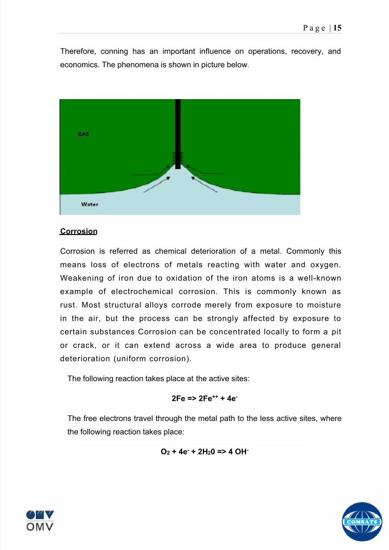
8102019 Gas sweetening Plant
httpslidepdfcomreaderfullgas-sweetening-plant 1962
P a g e | 15
Therefore conning has an important influence on operations recovery and
economics The phenomena is shown in picture below
Corrosion
Corrosion is referred as chemical deterioration of a metal Commonly this
means loss of electrons of metals reacting with water and oxygen
Weakening of iron due to oxidation of the iron atoms is a well-known
example of electrochemical corrosion This is commonly known as
rust Most structural alloys corrode merely from exposure to moisture
in the air but the process can be strongly affected by exposure to
certain substances Corrosion can be concentrated locally to form a pit
or crack or it can extend across a wide area to produce general
deterioration (uniform corrosion)
The following reaction takes place at the active sites
2Fe =gt 2Fe++ + 4e-
The free electrons travel through the metal path to the less active sites where
the following reaction takes place
O2 + 4e- + 2H20 =gt 4 OH-
8102019 Gas sweetening Plant
httpslidepdfcomreaderfullgas-sweetening-plant 2062
P a g e | 16
Recombination of these ions at the active surface produce the following
reaction which yields the iron-corrosion product ferrous hydroxide
2Fe + O2 + 2H2O =gt 2Fe (OH) 2
CORROSION PROTECTION SYSTEM
Coatings and painting
Painting and the application of enamel bitumen and PVC
coating are the most common anti-corrosion treatments They
work by providing a barrier of corrosion-resistant material
between the damaging environment and the structural material
Corrosion Inhibitors
Corrosion inhibitor is injected into the flow lines as mentioned in
detail on page 8
Cathodic Protection
Cathodic Protection (CP) is a technique used to control the corrosion of a
metal surface by making it the cathode of an electrochemical cell It
converts all of the anodic (active) sites on the metal surface to cathodic
(passive) sites by supplying electrical current (or free electrons) from an
alternate source It is accomplished in two ways
a) A simple method of protection connects protected metal to a more easily
corroded sacrificial metal to act as the anode The sacrificial metal then
corrodes instead of the protected metal The process is similar to a simple
DC cell in which the more active metal becomes the anode and corrodes
whereas the less active metal becomes the cathode and is protected
b) For larger structures galvanic anodes cannot economically deliver enough
current to provide protection Therefore impressed current cathodic
protection (ICCP) systems are used These consist of anodes connected
to a DC power source In remote areas power sources such as solar
panels may be used The output DC negative terminal is connected to the
8102019 Gas sweetening Plant
httpslidepdfcomreaderfullgas-sweetening-plant 2162
8102019 Gas sweetening Plant
httpslidepdfcomreaderfullgas-sweetening-plant 2262
P a g e | 18
frequently to limit liquid holdup and minimize the slug volumes of liquid which can
be generated by the system
Coating
Pigs may be used to apply internal pipe coatings such as epoxy coating
materials in operating pipelines Pigs may also be used with corrosion inhibitors
to distribute and coat the entire internal wetted perimeter
Inspection
Pigs are being used more frequently as inspection tools Gauging or sizing pigs
are typically run following the completion of new construction or line repair to
determine if there are any internal obstacles bends or buckles in the pipe Pigs
can also be equipped with cameras to allow viewing of the pipe internals
Electronic intelligent or smart ldquopigsrdquo that use magnetic and ultrasonic systems
have been developed and refined that locate and measure internal and external
corrosion pitting dents buckles and any other anomalies in the pipe wall
Intelligent pigs
The accuracy of location and measurement of anomalies by the intelligent pigs
has continued to improve Initially the electronics and power systems were so
large that intelligent pigs could be used only in lines 30 in and greater in size
The continued sophistication and miniaturization of the electronic systems used
in the intelligent pigs has allowed the development of smaller pigs that can be
used in small-diameter pipelines Newly enacted DOT pipeline-integrity
regulations and rules acknowledge the effectiveness of the intelligent pigs and
incorporate their use in the pipeline-integrity testing process
Compressors
A gas compressor is a mechanical device that increases the pressure of a gas by
reducing its volume Gas pressure is increased by forcing gas molecules together
to reduce gas volume When volume is reduced gas pressure increases
All gases have large spaces among their molecules These spaces could be
enhanced further and decreased by doing some work Work done which is used
8102019 Gas sweetening Plant
httpslidepdfcomreaderfullgas-sweetening-plant 2362
P a g e | 19
for the enhancement of these spaces is called expansion and work done to
minimize these spaces is called compression All gases while expansion
produces cooling effect and while compression of gases raises there
temperature Compression is a term used to force gases to occupy smaller
volumes by increasing their pressure Volume of gases is interlinked with
temperature and pressure of the gas which is cleared by 2 laws govern gas
compressions
Boyles Law
Charles Law
The main types of compressor are listed below
Front End Compressor
The plant currently processes gas from a number of wells The flow and pressure
from some of these wells (currently K-10 K-11 amp K-12) has declined and they
cannot be fed directly into the Central Processing Facility To recover the
maximum gas reserves from these wells a Front End Compressor is employed
The compressor is a two stage double acting gas engine driven reciprocating
(PT) compressor Double acting means that gas is compressed on each end of
the piston It normal operates with a speed range of 600 to 900 RPM and isequipped with four compressor cylinders two for each stage Each cylinder is
8102019 Gas sweetening Plant
httpslidepdfcomreaderfullgas-sweetening-plant 2462
P a g e | 20
also equipped with a variable volume head end pocket
In case of compressor emergency shutdown the production chokes and the
Upper Master Valves on the on line wells will close and operator will be notified in
central control room Sweet gas from gas distribution network is used to operate the
gas engine driver of the compressor package The detailed scheme of working is
shown in figure (page 22 )
PT Reciprocating Compressor
The mechanical cycle of piston tube reciprocating compressor comprises four
strokes the expansion stroke the intake stroke the compression stroke and the
discharge stroke
Expansion Stroke
As the piston moves back on the expansion stroke the chamber volume
increases and the pressure drop As the pressure drops the discharge valve
closes since there is greater pressure in the discharge line than in the chamber
Intake Stroke
As the piston moves back during the intake stroke the pressure decreases until it
is less than the pressure in the inlet line This higher intake pressure opens the
inlet valve and gas rushes into the cylinder equalizing the pressure there with
the intake pressure The compression chamber is now at or near the intake
pressure
Compression Stroke
The piston now starts the compression stroke by moving forward decreasing the
chamber volume and increasing the pressure The increased pressure is now
higher than the intake pressure causing the intake valve to close
Discharge Stroke
The piston continues to move to the left during the discharge stroke This creates
an increase in chamber pressure until it is greater than the discharge pressure
When this happens the Discharge valve opens and the compressed air from the
8102019 Gas sweetening Plant
httpslidepdfcomreaderfullgas-sweetening-plant 2562
P a g e | 21
cylinder goes into the discharge line The compression cycle is then repeated
from the stage
Compressor Capacity
The capacity of the compressor depends upon cylinder displacement That
displacement is simply the volume that the piston displaces (moves) as it travels
from one end of the cylinder to the other Capacity and displacement is equal to
the cross-sectional area of the cylinder times the length of the stroke
Lubrication and Cooling
Lubricating oil is circulated through the system by a gear pump which is chain
driven from the engine crank shaft The oil pump is mounted on the engine front
housing
The pump operates between 30 - 40 psig
8102019 Gas sweetening Plant
httpslidepdfcomreaderfullgas-sweetening-plant 2662
P a g e | 22
A circulating pump deliver cooling water to the water jackets in the cylinder block
flowing around the cylinder liners and is directed into the cylinder heads Each
cylinder head has water cooled exhaust elbows which outlet the water into the
water cooled exhausts From the end of engine the water flows to compressor
1st and 2nd stage cylinders and compressor lube oil cooler (LOwater heat
exchanger) The water from the compressor cylinder and lube oil cooler returns
to engine water cooled exhaust
Figure Flow diagram of Front End Compressor
8102019 Gas sweetening Plant
httpslidepdfcomreaderfullgas-sweetening-plant 2762
P a g e | 23
Centrifugal Compressor
Centrifugal compressors are machines in which velocity and pressure given to air
or gas in a radial direction by one or more impellers diffuser combination In a
centrifugal compressor the mechanical energy is increased by centrifugal action
The gas enters the suction eye of a high speed rotary element called the impeller
which carries radial vanes integrally cast in it As the impeller rotates the blades
of the impeller force the gas outward from the center the impeller to the outer rim
of impeller the increase in velocity of the gas creates a flow pressure area at the
eye of the impeller The gas at the outer rim of the impeller is forced in to a
passage way called a diffuser where the velocity decreases in the pressure of the
gas
Inlet
The inlet to a centrifugal compressor is typically a simple pipe It may include
features such as a valve and both pressure and temperature instrumentation
Centrifugal impeller
The key component that makes a compressor centrifugal is the centrifugal
impeller shown above It is the impellers rotating set of vanes (or blades) that
gradually raises the energy of the working gas This is identical to an axial
compressor with the exception that the gases can reach higher velocities and
energy levels through the impellers increasing radius
8102019 Gas sweetening Plant
httpslidepdfcomreaderfullgas-sweetening-plant 2862
P a g e | 24
Diffuser
The next key component to the simple centrifugal compressor is the diffuser
Downstream of the impeller in the flow path it is the diffusers responsibility to
convert the kinetic energy (high velocity) of the gas into pressure by gradually
slowing (diffusing) the gas velocity
SEPERATORS
A well-stream is a mixture of gases hydrocarbon liquids water solids and
contaminants Due to variations in pressure and temperature gases evolve from
the liquids water vapor condenses and some of the well-stream changes to liquid
and free gas The separation of well-stream fluids takes place in a separator This
pressure vessel is manufactured in three forms
1 horizontal
2 vertical
3 spherical
To help separation the vessel is normally designed with a series of internal
fittings These fittings are built into the separator to ensure total phase separation
of the well-stream
In gas plants separators are given alternative names due to the function they
perform in the process system A scrubber does a similar job to a knockout drum
However the scrubber usually separates a stream containing high gas-to-liquid
ratios The knockout drum is used where a high degree of liquids are entrained in
the gas
Fluid flow from a well can include gas condensable liquid vapors water water
vapor crude oil and solids As well-stream fluids reach ground level where
pressure is lower than in the reservoir the capacity of the liquid to hold gas in
solution decreases and gas separates out of the oil
Separation depends upon the effect of gravity to separate liquids For adequate
separation one fluid must be lighter than the other fluid For example distillates
8102019 Gas sweetening Plant
httpslidepdfcomreaderfullgas-sweetening-plant 2962
P a g e | 25
(gasoline kerosene etc) and crude oil will not separate in a vessel because they
tend to dissolve in each other Because a separator basically depends upon
gravity to separate the fluids the ease with which separation takes place
depends upon the difference in density of the fluids
Droplets of liquid will separate from gas provided
a) The gas remains in the separator long enough
b) The gas flow remains constant to provoke separation
The difference in density between a gas and liquid will therefore determine the
maximum flow rate of liquid in the vessel
Figure Two phase horizontal separator
Gas bubbles in the liquid will break out in some oil field applications in 30 to 60
seconds Consequently the separator is designed so that the liquid remains in
the vessel for 30 to 60 seconds The length of time that a liquid remains in the
vessel is called its residence time Residence time differs widely from field to field
depending upon viscosity and API Gravity
Another important factor which must be considered is temperature Generally a
decrease in operating temperature will increase the liquid recovery in a separator
8102019 Gas sweetening Plant
httpslidepdfcomreaderfullgas-sweetening-plant 3062
P a g e | 26
as the gas condenses By reducing the pressure on the fluid flash separation
occurs resulting in a flow through the separator which is controlled by external
instrumentation
COALESCENCE
Another important principle in fluid separation is that of coalescence This means
the coming together of liquid droplets created by the force of gravity
A common example of coalescing occurs when drops of water form on the
windshield of a car as it is driven in fog As the tiny drops or water which make up
the fog strike the windshield they combine and eventually form a drop large
enough to run down the glass
Several of the internal devices of a separator such as deflector plates
straightening vanes and even the vessel walls are forms of coalescers In each
vessel drops of liquid adhere to the surface of the device and combine with other
8102019 Gas sweetening Plant
httpslidepdfcomreaderfullgas-sweetening-plant 3162
P a g e | 27
drops until the drop is large enough to fall out The effectiveness of separation
will also depend upon the total amount of coalescing surface area that is present
There are many different types of separators used in the Oil amp Gas industry
Consequently separators are manufactured with one two or several internal
fittings depending on their use and quick removal of these fluids from the vessel
DEFLECTOR PLATES
These are fitted in front of the inlet to the separator and can be net or
dish-shaped Their purpose is to absorb the impact of the incoming fluids and to
encourage the separation of gas and liquids They also slow the flow rate of the
liquids through the vessel
WEIRS
A weir is a metal wall which is fitted across the inside of the vessel normally to a
height of 50 of the overall height of the separator Its purpose is to assist the
process of three phase separation The inlet fluids (oil plus water) are given time
to separate in the liquid accumulation section The water level (interface) is
normally controlled at 50 of the height of the weir Oil floating on the wateroverflows the weir and accumulates in the small oil compartment where it is
drawn off under level control
CENTRIFUGAL DEVICES
These are used in both vertical and horizontal separators for gas-liquid
separation The device imparts a swirling motion to the fluids entering the vessel
Centrifugal force causes the heavier liquids to travel outwards towards the walls
of the vessel and the lighter gases to flow up the centre Centrifugal devices are
also known as cyclones
VORTEX BREAKERS
When liquid flows through a drain outlet a vortex (whirlpool) will form This can
be seen when we pull the plug from a sink or bath tub The same would happen
as water and oil flow from the separator This condition a vortex could allow gas
to flow down the centre of the whirlpool and enter the liquid phase causing
8102019 Gas sweetening Plant
httpslidepdfcomreaderfullgas-sweetening-plant 3262
P a g e | 28
pressurizing of tanks etc To stop this happening vortex breakers are fitted to all
liquid outlets Although they come in a number of different designs vortex
breakers all serve the same purpose - to prevent a whirlpool from forming
MIST OR DEMISTER PADS
The gas which is released from the fluids in the separator still contains droplets of
oil and water which coalesce and fall when the drops get large enough The
demister pad assists in this process Made from knitted wire and contained within
a sturdy frame it causes the gas to continually change its direction of flow
Because gas changes direction far easier than liquid the gas will flow around
each strand of wire whilst the liquid entrained in the gas stream will continue and
stick to the wire
COALESCING PLATES
There are several different forms of coalescing devices the most common of
which are coalescing plates These plates are mounted in the flow stream of the
fluids and assist in breaking down oil-water emulsions The fluid is forced to
follow a path that constantly changes direction This causes the water droplets to
gather together or coalesce and fall to the bottom of the separator The same
principle is used to separate gas and oil mixtures when the oil droplets are
induced to coalesce Simply stated every surface within the separator including
the separator walls assists with the coalescing process
STRAIGHTENlNG VANES
These are often fitted to horizontal separators to remove turbulence in the gas
stream after initial separation at the inlet deflector
FLOAT SHEILD
Internal floats are used as level controllers Any agitation of the liquid surface or
the effect of coalesced liquids falling on the float may cause control problems
Therefore a float shield is fitted to enclose the float creating an area of still liquid
8102019 Gas sweetening Plant
httpslidepdfcomreaderfullgas-sweetening-plant 3362
P a g e | 29
MEMBRANES
The gas contains 12 carbon dioxide and 22 ppm of hydrogen sulphide at 115oF
and 1100 psig This needs to be removed before the gas can be exported The
majority of carbon dioxide hydrogen sulphide and water is removed by means of
membranes
Membranes are thin semipermeable barriers that selectively separate some
compounds from others Currently the only commercially workable membranes
used for CO2 removal are polymer based for example cellulose acetate
polyimides polyamides polysulfone polycarbonates and polyetherimide The
membrane does not operate as a filter where small molecules are separated
from larger ones through a medium with pores rather it separates based on how
well different compounds dissolve into the membrane and diffuse through it The
membranes are manufactured in flat sheets consisting of an extremely thin
nonporous layer mounted on a much-thicker and highly porous layer of the same
material providing mechanical strength The flat sheets are combined into a
spiral-wound element (Figure below) Feed gas enters along the side of the
membrane and passes through the feed spacers As the gas travels between
membrane sheets CO2 H2S and H2O permeate through the membrane and are
collected in the permeate tube The driving force for transport is the high-feed
pressure and low-permeate pressures The gas on the feed side that does not
permeate leaves through the side of the element opposite the feed position Once
the membranes have been manufactured into elements six to 12 elements are
joined together and inserted into a tube Multiple tubes are mounted on skids in a
horizontal orientation
8102019 Gas sweetening Plant
httpslidepdfcomreaderfullgas-sweetening-plant 3462
P a g e | 30
Figure Membrane general Working
In high H2S applications most polymers have been shown to have very little
resistance to H2S plasticization (ldquosofteningrdquo of the membrane) and as a
consequence can only be used at very low H2S partial pressure limits Cellulose
acetate membranes in contrast have been shown to be applicable at extreme
H2S partial pressure conditions It is these membranes that have been utilized in
the testing to determine the limits of membrane performance in high H 2S
applications
The primary membranes used in Kadanwari facility are Cellulose acetate
Cellulose acetic acid and acetic anhydride are mixed together and reacted to
form cellulose acetate polymers This process is aided by the addition of a small
amount of sulfuric acid which is subsequently neutralized during processing
However the membranes are bought from UOP (vendor) and installed for use
8102019 Gas sweetening Plant
httpslidepdfcomreaderfullgas-sweetening-plant 3562
P a g e | 31
How membrane work
The basic principle of separation is selectivity of certain components of a mixture
for the membrane For example the cellulose acetate membrane has very high
selectivity for CO2 and H2S as compared to CH4 Therefore such type of
membrane can be used in gas sweetening process
The selectivity is directly related to the Permeability of gas which accounts that
which gas can pass across the membrane more easily In simple words
membranes being polymer materials are made of long chains of molecules The
different structure of polymer materials only allow selective molecules to pass
through them depending upon chemical and physical compatibility Thus
permeability depends upon choice of polymer
The permeability is determined by permeability coefficient (P) and is product of
solubility (S) and diffusivity (D)
P = S D
Solubility
The solubility is mainly determined by ease of condensation Heavy molecules
are more readily condensed Therefore higher molecular weighted molecules will
more easily condensed and therefore have greater solubility
Molecule Molecular weight
CH4 16
H2S 34
CO2 44
8102019 Gas sweetening Plant
httpslidepdfcomreaderfullgas-sweetening-plant 3662
P a g e | 32
Diffusivity
Diffusivity is ease of molecule to penetrate into some material It depends on size
of gas molecule Here size of molecule is not to be confused by molecular weight
it is the size of the structure Eg the size of O2 molecule is smaller than N2
Molecule Molecular Diameter (Ao)
CO2 33
H2S 36
Ch4 40
For cellulose acetate
DCO2DCH4 S CO2S CH4 P CO2P CH4
45 73 308
Chemical degradation
Cellulose acetate polymer is chemically degraded by a process called hydrolysis
which means breaking apart by the addition of water This is a chemical reaction
in which water is added to the cellulose acetate polymer causing the release of
acetic acid molecules This process proceeds stepwise until all the acetate
groups are released resulting in the reformation of cellulose Moreover alcohols
aromatic hydrocarbons or solvents with chlorine nitro benzene or similar
aromatic solvents will harm the membrane It will expand and lose plastification in
contact with them
Effect of Temperature
The permeation rates of all gases increases with increasing temperature
however membrane selectivity for CO2 over hydrocarbon decreases at higher
8102019 Gas sweetening Plant
httpslidepdfcomreaderfullgas-sweetening-plant 3762
P a g e | 33
temperature Consequently CO2 removal will improve as operating temperature
increases but hydro carbon recovery will decrease
Primary Membrane
The primary membranes comprise of two trains Each train consists of two
sections AB and CD each section consists of a 30 tube membrane skid (A and
C) followed by a 25 tube skid (B and D) The conditioned gas (after pre-
treatment) enters the primary membrane via the particulate filter adjacent to the
skid The gas is fed to the membranes through a common inlet manifold which
supplies primary membranes skids A and C A pressure control loop located
upstream of the manual inlet isolation valve is provided to maintain a constant
supply pressure to the membrane skid and to allow for preheating at the inlet
prior to skid start-up This pressure control loop can also be used during start-up
to control the pressurization of the pretreatment skid and associated pipes to the
primary membranes
The gas passes through membrane skid A the residual gas exiting the membrane
skid is sent to skid B and the permeate to common permeate discharge header An
identical arrangement is provide on the inlet to skid C as provided on skid A Theresidual gas from skid B combines with the residual gas from skid D in a common
discharge header and is then sent to the H2S polishing towers via the feed coolers
on the pre-treatment skid The permeate from skid B is sent to the common
permeate discharge header The permeate discharge header sends the gas to
either the recycle compressor or the vent header via a pressure control loop
Overpressure protection for the membranes is provided by a pressure safety valve
on the supply header to the membrane banks
8102019 Gas sweetening Plant
httpslidepdfcomreaderfullgas-sweetening-plant 3862
P a g e | 34
Secondary (Recycle) Membrane
The recycle membranes comprise of a single train with two skids each with four
banks of membrane tubes The conditioned gas from the discharge of the recycle
pre-treatment skid is routed to the first recycle membrane skid The gas passes
through the membranes the residual gas is fed to primary membrane (skid A) inlet
via feed gas cooler and permeate to the common permeate discharge header An
identical arrangement is provide on the inlet to skid B Permeate from the recycle
membrane skids A and B is routed to the vent header Some portion of permeate is
heated and sent for regeneration in Mem-Guard units Nitrogen purge can be
connected downstream of the inlet isolation valve on each skid to enable the
membrane tubes to be purged and left pressurized during prolonged shutdown
8102019 Gas sweetening Plant
httpslidepdfcomreaderfullgas-sweetening-plant 3962
P a g e | 35
Figure Flow Diagram of Recycle membrane unit
8102019 Gas sweetening Plant
httpslidepdfcomreaderfullgas-sweetening-plant 4062
P a g e | 36
ADVANTAGES OF MEMBRANE SYSTEMS
Membrane systems have major advantages over more-traditional methods of
acid gas removal
Lower capital cost Membrane systems are skid mounted and so the
scope cost and time taken for site preparation are minimal Installation
costs are significantly lower than alternative technologies especially for
remote areas Furthermore no additional facilities for solvent storage and
water treatment needed by other processes are required
Lower operating costs The only major operating cost for single-stage
membrane systems is membrane replacement This cost is significantly
lower than the solvent replacement and energy costs associated with
traditional technologies The improvements in membrane and
pretreatment design allow a longer useful membrane life which further
reduces operating costs The energy costs of multistage systems with
large recycle compressors are usually comparable to those for traditionaltechnologies
Deferred capital investment Often contracted sales-gas flow rates
increase over time as more wells are brought on-line With traditional
technologies the system design needs to take this later production into
account immediately and so the majority of the equipment is installed
before it is even needed The modular nature of membrane systems
means that only the membranes that are needed at start-up need be
installed The rest can be added either into existing tubes or in new skids
only when they are required
Operational simplicity and high reliability Because single-stage
membrane systems have no moving parts they have almost no
8102019 Gas sweetening Plant
httpslidepdfcomreaderfullgas-sweetening-plant 4162
P a g e | 37
unscheduled downtime and are extremely simple to operate They can
operate unattended for long periods of time The addition of a recycle
compressor adds some complexity to the system but still much less than
with a solvent- or adsorbent-based technology Multistage systems can be
operated at full capacity as single-stage systems when the recycle
compressor is down
Good weight and space efficiency Skid construction can be optimized
to the space available This space efficiency is especially important for
offshore environments where deck area is at a premium and is the
reason why so many new offshore developments have chosen to use
membranes for acid gas removal Figure 6 illustrates the space efficiency
of membrane systems The membrane unit in the lower left corner
replaced all the amine and glycol plant equipment shown in the rest of the
picture
Adaptability Because membrane area is dictated by the percentage of
acid gas removal rather than absolute acid gas removal small variations
in feed acid gas content hardly change the sales-gas acid gas
specification For example a system designed for 10 down to 3 acid
gas removal produces a 35 product from a 12 feed gas and a 5
product from a 15 feed gas
Design efficiency The membrane and pretreatment systems integrate a
number of operations such as dehydration CO2 and H2S removal dew-
point control and mercury removal Traditional acid gas removal
technologies require all of these operations as separate processes and
may also require additional dehydration because some technologies
saturate the product stream with water
8102019 Gas sweetening Plant
httpslidepdfcomreaderfullgas-sweetening-plant 4262
P a g e | 38
Power generation The permeate gas from membrane systems can be
used to provide fuel gas for power generation either for a recycle
compressor or other equipment
Ideal for debottlenecking Because expanding solvent- or adsorbent-
based acid gas removal plants without adding additional trains is difficult
an ideal solution is to use membranes for bulk acid gas removal and leave
the existing plant for final cleanup An additional advantage is that the
permeate gas from the membrane system can often be used as fuel for
the existing plant thus avoiding significant increase in hydrocarbon
losses
Environmentally friendly Membrane systems do not involve the
periodic removal and handling of spent solvents or adsorbents Permeate
gases can be flared used as fuel or re-injected into the well Items thatdo need disposal such as spent membrane elements can be incinerated
Ideal for remote locations Many of the factors mentioned above make
membrane systems a highly desirable technology for remote locations
where spare parts are rare and labor unskilled Furthermore solvents
storage and trucking water supply power generation or extensive
infrastructure are not required
Re-injection optimizations Since the permeate stream from the
membrane system can be operated at elevated pressures it is possible to
further pressurize by re-injection compression train
8102019 Gas sweetening Plant
httpslidepdfcomreaderfullgas-sweetening-plant 4362
P a g e | 39
Sorption
Sorption is a physical and chemical process by which one substance becomes
attached to another
It is of two main types
1 Absorption
2 Adsorption
Absorption
Absorption is a physical or chemical phenomenon or process in which atoms
molecules or ions enter some bulk phase ndash gas liquid or solid material This is a
different process from adsorption since molecules undergoing absorption are
taken up by the volume not by the surface (as in the case for adsorption)
Absorption process may be chemical (reactive) or physical (non-reactive)
Physical absorption
Physical absorption or non-reactive absorption is made between two phases ofmatter a liquid absorbs a gas or a solid absorbs a liquid
When a liquid solvent absorbs a gas mixture or part of it a mass of gas moves
into the liquid For example water may absorb oxygen from the air This mass
transfer takes place at the interface between the liquid and the gas at a rate
depending on both the gas and the liquid This type of absorption depends on the
solubility of gases the pressure and the temperature The rate and amount of
absorption also depend on the surface area of the interface and its duration in
time
When a solid absorbs a liquid mixture or part of it a mass of liquid moves into the
solid For example a clay pot used to store water may absorb some of the water
This mass transfer takes place at the interface between the solid and the liquid
at a rate depending on both the solid and the liquid
8102019 Gas sweetening Plant
httpslidepdfcomreaderfullgas-sweetening-plant 4462
P a g e | 40
Chemical absorption
Chemical absorption or reactive absorption is a chemical reaction between the
absorbed and the absorbing substances Sometimes it combines with physical
absorption This type of absorption depends upon the stoichiometry of the
reaction and the concentration of its reactants
Adsorption
Adsorption is the adhesion of atoms ions or molecules from a gas liquid or
dissolved solid to a surface This process creates a film of the adsorbate on the
surface of the adsorbent The binding to the surface is usually weak and
reversible Compounds with color and those that have taste or odor tend to bind
strongly Compounds that vibrate at frequencies in the visible spectrum are very
often are strongly adsorbed on activated carbon
The most common industrial adsorbents are activated carbon silica gel and
alumina because they present enormous surface areas per unit weight
Depending on the nature of attractive forces existing between the adsorbate and
adsorbent adsorption can be classified as
i) Physical adsorption
ii) Chemical adsorption
i) Physical adsorption (Physisorption)
In physical adsorption the forces of attraction between the molecules of the
adsorbate and the adsorbent are of the weak van der Waals type Since the
forces of attraction are weak the process of physisorption can be easily reversed
by heating or decreasing the pressure of the adsorbate (as in the case of gases)
8102019 Gas sweetening Plant
httpslidepdfcomreaderfullgas-sweetening-plant 4562
P a g e | 41
ii) Chemical adsorption (Chemisorption)
In chemisorption the forces of attraction between the adsorbate and the
adsorbent are very strong the molecules of adsorbate form chemical bonds with
the molecules of the adsorbent present in the surface
Adsorption is generally accompanied by release of energy that is most
adsorption processes are exothermic in nature Adsorption is a spontaneous
process therefore its free energy change is negative (∆Glt0) However the
entropy change associated with adsorption is generally negative because the
adsorbate molecules lose their translation freedom when they get attached to the
surface of the adsorbent Therefore in order for ∆G to be negative the enthalpy
change (∆H) must be sufficiently negative such that (∆G=∆H-T∆S) lt 0 This
explanation accounts for exothermic adsorption processes In cases where
endothermic adsorption occurs the entropy change ∆S is sufficiently positive
such that ∆G remains negative
Pre treatment
The main function of pretreatment skid is to provide membrane inlet specification
gas as mentioned by the vendor UOP It removes the contaminants that would
poison the membranes like dust solids (adsorbent particles) lube oil heavy
hydrocarbons etc It consists of
Feed Cooler
Feed Gas Scrubber
Filter Coalescer
Feed Gas Heater
Activated Carbon Guard Filter
Particle Filter
8102019 Gas sweetening Plant
httpslidepdfcomreaderfullgas-sweetening-plant 4662
8102019 Gas sweetening Plant
httpslidepdfcomreaderfullgas-sweetening-plant 4762
P a g e | 43
The regeneration is carried out by heated permeate gas from the recycle
membranes at 450oF The vessel is depressurized to 20 psi and heated gas is
introduced from top The gas carries out the adsorbed contaminants and leaves
the vessel from bottom cleaning the adsorbent This contaminated gas is burnt in
the flare
UOP the vendor of Memguard unit has never disclosed that what substance
MG3 and MG5 exactly are But as mentioned by vendor that both care class of
aluminosilicates Therefore MG3 can be potassium aluminosilicate and MG5 can
be Calcium aluminosilicate These are molecular sieves adsorbents Molecular
sieves are a microporous material which can selectively adsorb gases andliquids They are synthetic zeolites (crystalline metal aluminosilicates) which
upon dehydration can efficiently and selectively remove water or other
solvents The selectivity of a molecular sieve is determined by its pore size
molecules with a critical diameter which is less than the pore size will be
efficiently adsorbed while larger molecules will be excluded
8102019 Gas sweetening Plant
httpslidepdfcomreaderfullgas-sweetening-plant 4862
P a g e | 44
3A Molecular Sieve Adsorbent
The 3A molecular sieve adsorbent has a 3 angstrom (3A) pore size which means
that any molecule that is larger than the 3 angstrom pores will not be adsorbed
The 3A molecular sieve is the potassium type of A crystalline structure and is a
form of alkali Aluminosilicate For a 3A molecular sieve the sequence rate that
adsorption occurs is He Ne N and H2O
Due to the crystalline structure molecular sieves that have a 3 angstrom pore
size have a very high rate of adsorption and properties that promote a longer life
for products treated by the sieve The most common use for the 3A molecular
sieve is to remove water and moisture from materials that are in gas and liquid
form
5A Molecular Sieve Adsorbent
These are molecular sieve adsorbents with a pore size of 5 angstrom (5A) 5A
molecular sieves are unable to adsorb any molecules or impurities that are
smaller than 5A It is calcium form of type A crystalline structure and is form of analkali-aluminosilicate that is most commonly used to separate isomerous alkanes
from normal alkanes and to co-adsorb moisture and water along with carbon
dioxide from gases In additional 5A molecular sieves are used for gaseous
pressure swing adsorption (PSA)mdashthat is to separate particular gases from other
gases
Adsorption of nC4H10
Adsorption of nC4H10
Adsorption of C3H8 to C22H46
Adsorption of Freon-12 (dichlorodifluoromethane)
Natural gas drying
Normal- and iso-paraffin separation
Separation of aromatic
8102019 Gas sweetening Plant
httpslidepdfcomreaderfullgas-sweetening-plant 4962
P a g e | 45
Inlet Composition of Memguard vessel
COMPSOSITION MOLE
CARBON DIOXIDE 1096
MEHTANE 8593
ETHANE 173
PROPANE 023
I-BUTANE 008
N BUTANE 004
PENTANES 004
HEXANE + 000
NITROGEN 076
WATER 007
Outlet Composition of Memguard vessel
COMPSOSITION MOLE
CARBON DIOXIDE 1098
MEHTANE 8608
ETHANE 173
PROPANE 023
I-BUTANE 008N BUTANE 004
PENTANES 004
HEXANE + 000
NITROGENT 076
WATER 000
H2S polisher
The H2S polishing unit has been designed to treat 187 MMscfday of natural gas
containing up to 11 CO2 and 21 ppm H2S where the level of the CO2 and H2S
is reduced using a MemGuard Membrane separation unit The unit is situated
down-stream of the membrane unit and will further reduce the level of H2S in the
processed gas to a sales gas specification of 38 ppm
8102019 Gas sweetening Plant
httpslidepdfcomreaderfullgas-sweetening-plant 5062
P a g e | 46
This process uses three non-regenerable fixed bed absorber vessels using a low
temperature high activity absorbent The absorbent is a mixture of activated
metal oxides (mainly zinc oxide) The three towers can are generally operated in
parallel arrangement but on demand can be used in series (any of alternate
arrangements of A B C vessels) as shown in figure
The higher sales gas flow rate increased the catalyst consumption and
replacement frequency
ZnO + H2S =gt ZnS + H20
Routine samples are taken from the beds to provide a check on each bed
performance and to follow the saturation profile during the absorbent life After
the adsorbent has been fully utilized the adsorption vessels are recharged with
new adsorbent discarding the utilized one in a safe manner
109oF
1215 psig
Before H2S Polishing After H2S Polishing
8102019 Gas sweetening Plant
httpslidepdfcomreaderfullgas-sweetening-plant 5162
P a g e | 47
Figure
H2S Tower
Inlet pipe
4 Drums of 19mm
ceramic Balls
6 Micron mesh
5 Drums of 50mmceramic
1 Drums of19mm ceramic
01 Drums of6mm ceramic
112 drums of
Catalist ZnO
8102019 Gas sweetening Plant
httpslidepdfcomreaderfullgas-sweetening-plant 5262
P a g e | 48
Recycle Compressor
The permeate gas of the primary membrane unit carries recoverable amount of
CH4 It is fed to recycle membrane unit for further CH 4 recovery But the
permeate pressure from primary membranes which has been reduced to 12 psi
must be regenerated to 1200 psi for the gas to be fed again to the system For
this purpose we have employed recycle compressor The compressor is a four
stage centrifugal compressor It is driven by gas turbine of 31200 HP It has 25
MW producing capacity
Figure Recycle Compressor Process Flow Diagram
8102019 Gas sweetening Plant
httpslidepdfcomreaderfullgas-sweetening-plant 5362
P a g e | 49
Sales Gas Compressor
Gas from H2S polishing unit is sent to sales gas compressor where its pressure
is enhanced to 1100 psi so it may be injected to SNGPL high pressure trunk line
Sales gas compressor is single stage gas turbine driven
Figure Process Flow of Sales Gas Compressor
8102019 Gas sweetening Plant
httpslidepdfcomreaderfullgas-sweetening-plant 5462
P a g e | 50
Cooling Towers
A cooling tower is a heat rejection device which extracts waste heat to theatmosphere through the cooling of a water stream to a lower temperature Hot
water from the system enters the cooling tower and is distributed over the fill
(heat transfer surface) Air is induced or forced through the fill causing a small
portion of the water to evaporate This evaporation removes heat from the
remaining water which is collected in the cold water basin and returned to the
system to absorb more heat Each cooling tower line although operating under
the same basic principle of operation is arranged a little differently
Types
Natural draft mdash Utilizes buoyancy via a tall chimney Warm moist air naturally
rises due to the density differential compared to the dry cooler outside air Warm
moist air is less dense than drier air at the same pressure This moist air
buoyancy produces an upwards current of air through the tower
Mechanical draft mdash Uses power-driven fan motors to force or draw airthrough the tower
o Induced draft mdash A mechanical draft tower with a fan at the
discharge (at the top) which pulls air up through the tower The fan
induces hot moist air out the discharge This produces low entering
and high exiting air velocities reducing the possibility of
recirculation in which discharged air flows back into the air intake
o Forced draft mdash A mechanical draft tower with a blower type fan at
the intake The fan forces air into the tower creating high entering
and low exiting air velocities The low exiting velocity is much more
susceptible to recirculation This fanfill geometry is also known as
blow-through
8102019 Gas sweetening Plant
httpslidepdfcomreaderfullgas-sweetening-plant 5562
P a g e | 51
Forced Draft Cooling Tower Vs Induced Draft Cooling Tower
Induced Draft Cooling Tower have the ability to handle large water flow
rate than Forced Draft Cooling Tower
Induced Draft Cooling Tower is suitable for large cell sizes and fan sizes
as compared with Forced Draft Larger fan size may result in greater
efficiency and consequently lower power and sound level
Forced Draft Cooling Tower can be square or rectangular type only
however Induced Draft Cooling Towers can be round square or
rectangular type
Induced Draft Cooling Tower uses more compact ground area than Forced
Draft Cooling Tower equivalent capacity due to absence of fan on one
side
Fan equipment is warm exhaust air is less liable to icing up in winter
operation (Cold Countries)
Higher velocity in Forced Draft Cooling Tower cause drop in suspension
and cause additional static resistance to system
Configuration
There are two main configurations of factory assembled cooling towers crossflow
and counterflow In crossflow cooling towers the water flows vertically down the
fill as air flows horizontally across In counterflow cooling towers the water flows
vertically down the fill as air flows vertically up
Crossflow Configuration Counterflow Configuration
8102019 Gas sweetening Plant
httpslidepdfcomreaderfullgas-sweetening-plant 5662
P a g e | 52
Drift mdash Water droplets that are carried out of the cooling tower with the exhaust
air Drift droplets have the same concentration of impurities as the water entering
the tower The drift rate is typically reduced by employing baffle-like devices
called drift eliminators through which the air must travel after leaving the fill and
spray zones of the tower
Blow-out mdash Water droplets blown out of the cooling tower by wind generally at
the air inlet openings Water may also be lost in the absence of wind through
splashing or misting Devices such as wind screens louvers splash deflectors
and water diverters are used to limit these losses
Blow-down mdash The portion of the circulating water flow that is removed (usually
discharged to a drain) in order to maintain the amount of Total Dissolved Solids
(TDS) and other impurities at an acceptably low level Higher TDS concentration
in solution may result from greater cooling tower efficiency However the higher
the TDS concentration the greater the risk of scale biological growth and
corrosion
Make-up mdash The water that must be added to the circulating water system in
order to compensate for water losses such as evaporation drift loss blow-out
blow-down etc
Approach mdash The approach is the difference in temperature between the cooled-
water temperature and the entering-air wet bulb temperature
Range mdash The range is the temperature difference between the warm water inlet
and cooled water exit
Fill mdash Inside the tower fills are added to increase contact surface as well as
contact time between air and water to provide better heat transfer The efficiency
of the tower depends on the selection and amount of fill
8102019 Gas sweetening Plant
httpslidepdfcomreaderfullgas-sweetening-plant 5762
P a g e | 53
There are two types of fills that may be used
o Film type fill (causes water to spread into a thin film)
o Splash type fill (breaks up falling stream of water and interrupts its
vertical progress)
Important
Scale build up is controlled by adding chemicals to the cooling loop and diluting
the concentration by blow down and make-up Following chemicals are added to
the Cooling to control CorrosionSale and microbial growth
Corrosion Inhibitor To control corrosion in the Cooling system
Dispersant To kept ions in suspension to avoid settle down and buildup
Sodium hypo Chlorite To Control microbial Growth
Acid To control Alkalinity in the system
High Stress Polymer To run the system at higher conductivity It is a
multifunctional polymer for Zinc amp Phosphate stabilization in cooling tower
Fin Fan Cooler
Fin fan heat exchanger is simply a pressure vessel which cools a circulating fluid
within finned tubes by forcing ambient air over the exterior of the tubes A
common example of an air cooler is a carrsquos radiator Fin Fan Coolers are used in
any application where large quantities of heat need to be transferred This
includes chemical and petrochemical industries power stations waste-to-energy
facilities as well as steelworks
Fin Fan Cooler are used for two primary reasons
They increase plant efficiency
They are a green solution as compared to cooling towers and shell and
tube heat exchangers because they do not require an auxiliary water
8102019 Gas sweetening Plant
httpslidepdfcomreaderfullgas-sweetening-plant 5862
P a g e | 54
supply (water lost due to drift and evaporation plus no water treatment
chemicals are required)
Figure General Overview of Fin Fan Cooler
Produced Water
The produced water system receives liquid from the equipment Miano slug
catcher train 1 and 2 inlet separators and is fed to three phase separator where
water oil and gas is separated The gases produced are burnt in incinerator
whereas hydrocarbon liquid is stored to be sold Liquid from compressors
recycle inlet separator recycle feed scrubber high and low pressure slug
catchers is passed to degasser Separated water is injected down the earth
Incinerator
The term incinerate means to burn something until nothing is left but ashes An
incinerator is a unit or facility used to burn trash and other types of waste until it is
reduced to ash An incinerator is constructed of heavy well-insulated materials
so that it does not give off extreme amounts of external heat The high levels of
heat are kept inside the furnace or unit so that the waste is burned quickly and
efficiently If the heat were allowed to escape the waste would not burn as
completely or as rapidly
8102019 Gas sweetening Plant
httpslidepdfcomreaderfullgas-sweetening-plant 5962
P a g e | 55
Control System
The plant is controlled at CCR (Central Control Room) by PLCs (Programmable
Logic Controllers) through fiber optic control line All control parameters are
received at LER (Local Equipment Room) via two optic fiber control lines One
being primary and other secondary operating in redundancy ie if primary fails
control shifts to secondary These control parameters are sent to CCR via single
optic fiber cable
Safety System
Wellheads and Gas Processing Plant have their own Fire amp Gas detection
systems emergency shutdown (ESD) Plant has a fault tolerant controller It is
based on Triple Modular Redundant (TMR) architecture manufactured by
Triconex The TMR system is based on three isolated parallel control systems
integrated into one system The system operates on a two out of three voting
principle which provides high integrity error free uninterrupted operation with no
single point of failure The TMR receives inputs from Process Sensors Manual
Switches Fire amp Gas Detectors Packaged Equipment Control Systems and
Product Exporting Facilities The TMR carries out cause and effect processing on
the data received and where necessary produces output signals Outputs from
the TMR are hard wired directly to ESD shutdown and blow down valve
solenoids motor control instrumentelectrical interfaces to control electrical
drives package equipment logic control systems manifold area as well as
telecoms
The operator in central control room is able to accept alarms and once the fault
has been cleared reset the input All the control systems are centralized to a
single interface All the PLCs (Programmable Logic Controllers) communicate with
the servers and servers communicate with the clients through Ethernet connectivity
Centralization eases the navigation of different systems at a common interface
Emergency Shutdown
The ESD system receives inputs from field mounted instrumentation on the process
8102019 Gas sweetening Plant
httpslidepdfcomreaderfullgas-sweetening-plant 6062
P a g e | 56
and utility equipment and initiates executive actions appropriate to the level of ESD
The system is an Active system which is in standby and will activate when in an
alarm or fault condition The Kadanwari Gas Process Facility ESD system is
comprised of five (5) levels The emergency severity decreases with increasing ESD
level number
ESD 1
This shutdown level is automatically initiated by fire major gas leak or a detected
toxic atmosphere in the process area of the plant or manually from CCR A level 1
shutdown will cause all production to cease close all emergency shutdown
valves stop the process and shutdown of the main power generation The
emergency vent valves to the stack will open and in addition all equipment of zone 1
certified will be isolated This is the highest level of ESD and will cause the following
to occur
All Shutdown Valves (SDVs) on the process facility will close All slowdown Valves (BDVs) on the process facility will open
All Main Gas Driven Generators will be tripped
Emergency Diesel Generator will start
All electrical power to process and utility rotating equipment will be
isolated
Wellhead Choke Valves Close Wing Valves Close Upper Master Valve
(UMV) Close
ESD 2
This shutdown level is activated automatically if a major process or utility failure
occurs or manually from CCR All production to the plant from the wellhead is
stopped All emergency shutdown valves trip to their fail safe position
Venting shall be as specified This level of ESD will cause the following to occur
8102019 Gas sweetening Plant
httpslidepdfcomreaderfullgas-sweetening-plant 6162
P a g e | 57
All Shutdown Valves (SDVs) on the process facility will close
All electrical power to process and utility rotating equipment will be
isolated
Wellhead Choke Valve Close Wing Valves Close and Upper Master Valve(UMV) Close
ESD 3
The level 3 shutdown isolates and stops a single process train only Production
continues via the other train This ESD level is initiated by process conditions or
operator at local panel This level of ESD will cause the following to occur
ESD 3A Train 1 production to cease
ESD 3B Train 2 production to cease
All online wellhead choke valves go to minimum flow ie (1O )
ESD 4
A level 4 shutdown shall cease all production from an entire field either
Kadanwari or Miano upstream of the associated slug catchers ESD 4K for
Kadanwari amp ESD 4M for Miano This ESD level is initiated automatically by slug
catcher abnormal process conditions This level of ESD will cause the following
to occur
All SDVs close isolating the relevant slug catcher and its upstream gas
production facility from the Kadanwari Gas Processing Plant
All Wellhead Choke Valves Close Wing Valves Close and Upper MasterValves (UMV) of the relevant gas production facility Close
A parallel timer is provided to close within 10 second if not closed in given
time SSSV seals the well
ESD 5
A level 5 shutdown represents equipment shutdown for the protection of the
individual equipment without any change in the process This level of ESD is for the
protection of various pieces of equipment and is initiated by its own inputs eg
8102019 Gas sweetening Plant
httpslidepdfcomreaderfullgas-sweetening-plant 6262
8102019 Gas sweetening Plant
httpslidepdfcomreaderfullgas-sweetening-plant 2262
P a g e | 18
frequently to limit liquid holdup and minimize the slug volumes of liquid which can
be generated by the system
Coating
Pigs may be used to apply internal pipe coatings such as epoxy coating
materials in operating pipelines Pigs may also be used with corrosion inhibitors
to distribute and coat the entire internal wetted perimeter
Inspection
Pigs are being used more frequently as inspection tools Gauging or sizing pigs
are typically run following the completion of new construction or line repair to
determine if there are any internal obstacles bends or buckles in the pipe Pigs
can also be equipped with cameras to allow viewing of the pipe internals
Electronic intelligent or smart ldquopigsrdquo that use magnetic and ultrasonic systems
have been developed and refined that locate and measure internal and external
corrosion pitting dents buckles and any other anomalies in the pipe wall
Intelligent pigs
The accuracy of location and measurement of anomalies by the intelligent pigs
has continued to improve Initially the electronics and power systems were so
large that intelligent pigs could be used only in lines 30 in and greater in size
The continued sophistication and miniaturization of the electronic systems used
in the intelligent pigs has allowed the development of smaller pigs that can be
used in small-diameter pipelines Newly enacted DOT pipeline-integrity
regulations and rules acknowledge the effectiveness of the intelligent pigs and
incorporate their use in the pipeline-integrity testing process
Compressors
A gas compressor is a mechanical device that increases the pressure of a gas by
reducing its volume Gas pressure is increased by forcing gas molecules together
to reduce gas volume When volume is reduced gas pressure increases
All gases have large spaces among their molecules These spaces could be
enhanced further and decreased by doing some work Work done which is used
8102019 Gas sweetening Plant
httpslidepdfcomreaderfullgas-sweetening-plant 2362
P a g e | 19
for the enhancement of these spaces is called expansion and work done to
minimize these spaces is called compression All gases while expansion
produces cooling effect and while compression of gases raises there
temperature Compression is a term used to force gases to occupy smaller
volumes by increasing their pressure Volume of gases is interlinked with
temperature and pressure of the gas which is cleared by 2 laws govern gas
compressions
Boyles Law
Charles Law
The main types of compressor are listed below
Front End Compressor
The plant currently processes gas from a number of wells The flow and pressure
from some of these wells (currently K-10 K-11 amp K-12) has declined and they
cannot be fed directly into the Central Processing Facility To recover the
maximum gas reserves from these wells a Front End Compressor is employed
The compressor is a two stage double acting gas engine driven reciprocating
(PT) compressor Double acting means that gas is compressed on each end of
the piston It normal operates with a speed range of 600 to 900 RPM and isequipped with four compressor cylinders two for each stage Each cylinder is
8102019 Gas sweetening Plant
httpslidepdfcomreaderfullgas-sweetening-plant 2462
P a g e | 20
also equipped with a variable volume head end pocket
In case of compressor emergency shutdown the production chokes and the
Upper Master Valves on the on line wells will close and operator will be notified in
central control room Sweet gas from gas distribution network is used to operate the
gas engine driver of the compressor package The detailed scheme of working is
shown in figure (page 22 )
PT Reciprocating Compressor
The mechanical cycle of piston tube reciprocating compressor comprises four
strokes the expansion stroke the intake stroke the compression stroke and the
discharge stroke
Expansion Stroke
As the piston moves back on the expansion stroke the chamber volume
increases and the pressure drop As the pressure drops the discharge valve
closes since there is greater pressure in the discharge line than in the chamber
Intake Stroke
As the piston moves back during the intake stroke the pressure decreases until it
is less than the pressure in the inlet line This higher intake pressure opens the
inlet valve and gas rushes into the cylinder equalizing the pressure there with
the intake pressure The compression chamber is now at or near the intake
pressure
Compression Stroke
The piston now starts the compression stroke by moving forward decreasing the
chamber volume and increasing the pressure The increased pressure is now
higher than the intake pressure causing the intake valve to close
Discharge Stroke
The piston continues to move to the left during the discharge stroke This creates
an increase in chamber pressure until it is greater than the discharge pressure
When this happens the Discharge valve opens and the compressed air from the
8102019 Gas sweetening Plant
httpslidepdfcomreaderfullgas-sweetening-plant 2562
P a g e | 21
cylinder goes into the discharge line The compression cycle is then repeated
from the stage
Compressor Capacity
The capacity of the compressor depends upon cylinder displacement That
displacement is simply the volume that the piston displaces (moves) as it travels
from one end of the cylinder to the other Capacity and displacement is equal to
the cross-sectional area of the cylinder times the length of the stroke
Lubrication and Cooling
Lubricating oil is circulated through the system by a gear pump which is chain
driven from the engine crank shaft The oil pump is mounted on the engine front
housing
The pump operates between 30 - 40 psig
8102019 Gas sweetening Plant
httpslidepdfcomreaderfullgas-sweetening-plant 2662
P a g e | 22
A circulating pump deliver cooling water to the water jackets in the cylinder block
flowing around the cylinder liners and is directed into the cylinder heads Each
cylinder head has water cooled exhaust elbows which outlet the water into the
water cooled exhausts From the end of engine the water flows to compressor
1st and 2nd stage cylinders and compressor lube oil cooler (LOwater heat
exchanger) The water from the compressor cylinder and lube oil cooler returns
to engine water cooled exhaust
Figure Flow diagram of Front End Compressor
8102019 Gas sweetening Plant
httpslidepdfcomreaderfullgas-sweetening-plant 2762
P a g e | 23
Centrifugal Compressor
Centrifugal compressors are machines in which velocity and pressure given to air
or gas in a radial direction by one or more impellers diffuser combination In a
centrifugal compressor the mechanical energy is increased by centrifugal action
The gas enters the suction eye of a high speed rotary element called the impeller
which carries radial vanes integrally cast in it As the impeller rotates the blades
of the impeller force the gas outward from the center the impeller to the outer rim
of impeller the increase in velocity of the gas creates a flow pressure area at the
eye of the impeller The gas at the outer rim of the impeller is forced in to a
passage way called a diffuser where the velocity decreases in the pressure of the
gas
Inlet
The inlet to a centrifugal compressor is typically a simple pipe It may include
features such as a valve and both pressure and temperature instrumentation
Centrifugal impeller
The key component that makes a compressor centrifugal is the centrifugal
impeller shown above It is the impellers rotating set of vanes (or blades) that
gradually raises the energy of the working gas This is identical to an axial
compressor with the exception that the gases can reach higher velocities and
energy levels through the impellers increasing radius
8102019 Gas sweetening Plant
httpslidepdfcomreaderfullgas-sweetening-plant 2862
P a g e | 24
Diffuser
The next key component to the simple centrifugal compressor is the diffuser
Downstream of the impeller in the flow path it is the diffusers responsibility to
convert the kinetic energy (high velocity) of the gas into pressure by gradually
slowing (diffusing) the gas velocity
SEPERATORS
A well-stream is a mixture of gases hydrocarbon liquids water solids and
contaminants Due to variations in pressure and temperature gases evolve from
the liquids water vapor condenses and some of the well-stream changes to liquid
and free gas The separation of well-stream fluids takes place in a separator This
pressure vessel is manufactured in three forms
1 horizontal
2 vertical
3 spherical
To help separation the vessel is normally designed with a series of internal
fittings These fittings are built into the separator to ensure total phase separation
of the well-stream
In gas plants separators are given alternative names due to the function they
perform in the process system A scrubber does a similar job to a knockout drum
However the scrubber usually separates a stream containing high gas-to-liquid
ratios The knockout drum is used where a high degree of liquids are entrained in
the gas
Fluid flow from a well can include gas condensable liquid vapors water water
vapor crude oil and solids As well-stream fluids reach ground level where
pressure is lower than in the reservoir the capacity of the liquid to hold gas in
solution decreases and gas separates out of the oil
Separation depends upon the effect of gravity to separate liquids For adequate
separation one fluid must be lighter than the other fluid For example distillates
8102019 Gas sweetening Plant
httpslidepdfcomreaderfullgas-sweetening-plant 2962
P a g e | 25
(gasoline kerosene etc) and crude oil will not separate in a vessel because they
tend to dissolve in each other Because a separator basically depends upon
gravity to separate the fluids the ease with which separation takes place
depends upon the difference in density of the fluids
Droplets of liquid will separate from gas provided
a) The gas remains in the separator long enough
b) The gas flow remains constant to provoke separation
The difference in density between a gas and liquid will therefore determine the
maximum flow rate of liquid in the vessel
Figure Two phase horizontal separator
Gas bubbles in the liquid will break out in some oil field applications in 30 to 60
seconds Consequently the separator is designed so that the liquid remains in
the vessel for 30 to 60 seconds The length of time that a liquid remains in the
vessel is called its residence time Residence time differs widely from field to field
depending upon viscosity and API Gravity
Another important factor which must be considered is temperature Generally a
decrease in operating temperature will increase the liquid recovery in a separator
8102019 Gas sweetening Plant
httpslidepdfcomreaderfullgas-sweetening-plant 3062
P a g e | 26
as the gas condenses By reducing the pressure on the fluid flash separation
occurs resulting in a flow through the separator which is controlled by external
instrumentation
COALESCENCE
Another important principle in fluid separation is that of coalescence This means
the coming together of liquid droplets created by the force of gravity
A common example of coalescing occurs when drops of water form on the
windshield of a car as it is driven in fog As the tiny drops or water which make up
the fog strike the windshield they combine and eventually form a drop large
enough to run down the glass
Several of the internal devices of a separator such as deflector plates
straightening vanes and even the vessel walls are forms of coalescers In each
vessel drops of liquid adhere to the surface of the device and combine with other
8102019 Gas sweetening Plant
httpslidepdfcomreaderfullgas-sweetening-plant 3162
P a g e | 27
drops until the drop is large enough to fall out The effectiveness of separation
will also depend upon the total amount of coalescing surface area that is present
There are many different types of separators used in the Oil amp Gas industry
Consequently separators are manufactured with one two or several internal
fittings depending on their use and quick removal of these fluids from the vessel
DEFLECTOR PLATES
These are fitted in front of the inlet to the separator and can be net or
dish-shaped Their purpose is to absorb the impact of the incoming fluids and to
encourage the separation of gas and liquids They also slow the flow rate of the
liquids through the vessel
WEIRS
A weir is a metal wall which is fitted across the inside of the vessel normally to a
height of 50 of the overall height of the separator Its purpose is to assist the
process of three phase separation The inlet fluids (oil plus water) are given time
to separate in the liquid accumulation section The water level (interface) is
normally controlled at 50 of the height of the weir Oil floating on the wateroverflows the weir and accumulates in the small oil compartment where it is
drawn off under level control
CENTRIFUGAL DEVICES
These are used in both vertical and horizontal separators for gas-liquid
separation The device imparts a swirling motion to the fluids entering the vessel
Centrifugal force causes the heavier liquids to travel outwards towards the walls
of the vessel and the lighter gases to flow up the centre Centrifugal devices are
also known as cyclones
VORTEX BREAKERS
When liquid flows through a drain outlet a vortex (whirlpool) will form This can
be seen when we pull the plug from a sink or bath tub The same would happen
as water and oil flow from the separator This condition a vortex could allow gas
to flow down the centre of the whirlpool and enter the liquid phase causing
8102019 Gas sweetening Plant
httpslidepdfcomreaderfullgas-sweetening-plant 3262
P a g e | 28
pressurizing of tanks etc To stop this happening vortex breakers are fitted to all
liquid outlets Although they come in a number of different designs vortex
breakers all serve the same purpose - to prevent a whirlpool from forming
MIST OR DEMISTER PADS
The gas which is released from the fluids in the separator still contains droplets of
oil and water which coalesce and fall when the drops get large enough The
demister pad assists in this process Made from knitted wire and contained within
a sturdy frame it causes the gas to continually change its direction of flow
Because gas changes direction far easier than liquid the gas will flow around
each strand of wire whilst the liquid entrained in the gas stream will continue and
stick to the wire
COALESCING PLATES
There are several different forms of coalescing devices the most common of
which are coalescing plates These plates are mounted in the flow stream of the
fluids and assist in breaking down oil-water emulsions The fluid is forced to
follow a path that constantly changes direction This causes the water droplets to
gather together or coalesce and fall to the bottom of the separator The same
principle is used to separate gas and oil mixtures when the oil droplets are
induced to coalesce Simply stated every surface within the separator including
the separator walls assists with the coalescing process
STRAIGHTENlNG VANES
These are often fitted to horizontal separators to remove turbulence in the gas
stream after initial separation at the inlet deflector
FLOAT SHEILD
Internal floats are used as level controllers Any agitation of the liquid surface or
the effect of coalesced liquids falling on the float may cause control problems
Therefore a float shield is fitted to enclose the float creating an area of still liquid
8102019 Gas sweetening Plant
httpslidepdfcomreaderfullgas-sweetening-plant 3362
P a g e | 29
MEMBRANES
The gas contains 12 carbon dioxide and 22 ppm of hydrogen sulphide at 115oF
and 1100 psig This needs to be removed before the gas can be exported The
majority of carbon dioxide hydrogen sulphide and water is removed by means of
membranes
Membranes are thin semipermeable barriers that selectively separate some
compounds from others Currently the only commercially workable membranes
used for CO2 removal are polymer based for example cellulose acetate
polyimides polyamides polysulfone polycarbonates and polyetherimide The
membrane does not operate as a filter where small molecules are separated
from larger ones through a medium with pores rather it separates based on how
well different compounds dissolve into the membrane and diffuse through it The
membranes are manufactured in flat sheets consisting of an extremely thin
nonporous layer mounted on a much-thicker and highly porous layer of the same
material providing mechanical strength The flat sheets are combined into a
spiral-wound element (Figure below) Feed gas enters along the side of the
membrane and passes through the feed spacers As the gas travels between
membrane sheets CO2 H2S and H2O permeate through the membrane and are
collected in the permeate tube The driving force for transport is the high-feed
pressure and low-permeate pressures The gas on the feed side that does not
permeate leaves through the side of the element opposite the feed position Once
the membranes have been manufactured into elements six to 12 elements are
joined together and inserted into a tube Multiple tubes are mounted on skids in a
horizontal orientation
8102019 Gas sweetening Plant
httpslidepdfcomreaderfullgas-sweetening-plant 3462
P a g e | 30
Figure Membrane general Working
In high H2S applications most polymers have been shown to have very little
resistance to H2S plasticization (ldquosofteningrdquo of the membrane) and as a
consequence can only be used at very low H2S partial pressure limits Cellulose
acetate membranes in contrast have been shown to be applicable at extreme
H2S partial pressure conditions It is these membranes that have been utilized in
the testing to determine the limits of membrane performance in high H 2S
applications
The primary membranes used in Kadanwari facility are Cellulose acetate
Cellulose acetic acid and acetic anhydride are mixed together and reacted to
form cellulose acetate polymers This process is aided by the addition of a small
amount of sulfuric acid which is subsequently neutralized during processing
However the membranes are bought from UOP (vendor) and installed for use
8102019 Gas sweetening Plant
httpslidepdfcomreaderfullgas-sweetening-plant 3562
P a g e | 31
How membrane work
The basic principle of separation is selectivity of certain components of a mixture
for the membrane For example the cellulose acetate membrane has very high
selectivity for CO2 and H2S as compared to CH4 Therefore such type of
membrane can be used in gas sweetening process
The selectivity is directly related to the Permeability of gas which accounts that
which gas can pass across the membrane more easily In simple words
membranes being polymer materials are made of long chains of molecules The
different structure of polymer materials only allow selective molecules to pass
through them depending upon chemical and physical compatibility Thus
permeability depends upon choice of polymer
The permeability is determined by permeability coefficient (P) and is product of
solubility (S) and diffusivity (D)
P = S D
Solubility
The solubility is mainly determined by ease of condensation Heavy molecules
are more readily condensed Therefore higher molecular weighted molecules will
more easily condensed and therefore have greater solubility
Molecule Molecular weight
CH4 16
H2S 34
CO2 44
8102019 Gas sweetening Plant
httpslidepdfcomreaderfullgas-sweetening-plant 3662
P a g e | 32
Diffusivity
Diffusivity is ease of molecule to penetrate into some material It depends on size
of gas molecule Here size of molecule is not to be confused by molecular weight
it is the size of the structure Eg the size of O2 molecule is smaller than N2
Molecule Molecular Diameter (Ao)
CO2 33
H2S 36
Ch4 40
For cellulose acetate
DCO2DCH4 S CO2S CH4 P CO2P CH4
45 73 308
Chemical degradation
Cellulose acetate polymer is chemically degraded by a process called hydrolysis
which means breaking apart by the addition of water This is a chemical reaction
in which water is added to the cellulose acetate polymer causing the release of
acetic acid molecules This process proceeds stepwise until all the acetate
groups are released resulting in the reformation of cellulose Moreover alcohols
aromatic hydrocarbons or solvents with chlorine nitro benzene or similar
aromatic solvents will harm the membrane It will expand and lose plastification in
contact with them
Effect of Temperature
The permeation rates of all gases increases with increasing temperature
however membrane selectivity for CO2 over hydrocarbon decreases at higher
8102019 Gas sweetening Plant
httpslidepdfcomreaderfullgas-sweetening-plant 3762
P a g e | 33
temperature Consequently CO2 removal will improve as operating temperature
increases but hydro carbon recovery will decrease
Primary Membrane
The primary membranes comprise of two trains Each train consists of two
sections AB and CD each section consists of a 30 tube membrane skid (A and
C) followed by a 25 tube skid (B and D) The conditioned gas (after pre-
treatment) enters the primary membrane via the particulate filter adjacent to the
skid The gas is fed to the membranes through a common inlet manifold which
supplies primary membranes skids A and C A pressure control loop located
upstream of the manual inlet isolation valve is provided to maintain a constant
supply pressure to the membrane skid and to allow for preheating at the inlet
prior to skid start-up This pressure control loop can also be used during start-up
to control the pressurization of the pretreatment skid and associated pipes to the
primary membranes
The gas passes through membrane skid A the residual gas exiting the membrane
skid is sent to skid B and the permeate to common permeate discharge header An
identical arrangement is provide on the inlet to skid C as provided on skid A Theresidual gas from skid B combines with the residual gas from skid D in a common
discharge header and is then sent to the H2S polishing towers via the feed coolers
on the pre-treatment skid The permeate from skid B is sent to the common
permeate discharge header The permeate discharge header sends the gas to
either the recycle compressor or the vent header via a pressure control loop
Overpressure protection for the membranes is provided by a pressure safety valve
on the supply header to the membrane banks
8102019 Gas sweetening Plant
httpslidepdfcomreaderfullgas-sweetening-plant 3862
P a g e | 34
Secondary (Recycle) Membrane
The recycle membranes comprise of a single train with two skids each with four
banks of membrane tubes The conditioned gas from the discharge of the recycle
pre-treatment skid is routed to the first recycle membrane skid The gas passes
through the membranes the residual gas is fed to primary membrane (skid A) inlet
via feed gas cooler and permeate to the common permeate discharge header An
identical arrangement is provide on the inlet to skid B Permeate from the recycle
membrane skids A and B is routed to the vent header Some portion of permeate is
heated and sent for regeneration in Mem-Guard units Nitrogen purge can be
connected downstream of the inlet isolation valve on each skid to enable the
membrane tubes to be purged and left pressurized during prolonged shutdown
8102019 Gas sweetening Plant
httpslidepdfcomreaderfullgas-sweetening-plant 3962
P a g e | 35
Figure Flow Diagram of Recycle membrane unit
8102019 Gas sweetening Plant
httpslidepdfcomreaderfullgas-sweetening-plant 4062
P a g e | 36
ADVANTAGES OF MEMBRANE SYSTEMS
Membrane systems have major advantages over more-traditional methods of
acid gas removal
Lower capital cost Membrane systems are skid mounted and so the
scope cost and time taken for site preparation are minimal Installation
costs are significantly lower than alternative technologies especially for
remote areas Furthermore no additional facilities for solvent storage and
water treatment needed by other processes are required
Lower operating costs The only major operating cost for single-stage
membrane systems is membrane replacement This cost is significantly
lower than the solvent replacement and energy costs associated with
traditional technologies The improvements in membrane and
pretreatment design allow a longer useful membrane life which further
reduces operating costs The energy costs of multistage systems with
large recycle compressors are usually comparable to those for traditionaltechnologies
Deferred capital investment Often contracted sales-gas flow rates
increase over time as more wells are brought on-line With traditional
technologies the system design needs to take this later production into
account immediately and so the majority of the equipment is installed
before it is even needed The modular nature of membrane systems
means that only the membranes that are needed at start-up need be
installed The rest can be added either into existing tubes or in new skids
only when they are required
Operational simplicity and high reliability Because single-stage
membrane systems have no moving parts they have almost no
8102019 Gas sweetening Plant
httpslidepdfcomreaderfullgas-sweetening-plant 4162
P a g e | 37
unscheduled downtime and are extremely simple to operate They can
operate unattended for long periods of time The addition of a recycle
compressor adds some complexity to the system but still much less than
with a solvent- or adsorbent-based technology Multistage systems can be
operated at full capacity as single-stage systems when the recycle
compressor is down
Good weight and space efficiency Skid construction can be optimized
to the space available This space efficiency is especially important for
offshore environments where deck area is at a premium and is the
reason why so many new offshore developments have chosen to use
membranes for acid gas removal Figure 6 illustrates the space efficiency
of membrane systems The membrane unit in the lower left corner
replaced all the amine and glycol plant equipment shown in the rest of the
picture
Adaptability Because membrane area is dictated by the percentage of
acid gas removal rather than absolute acid gas removal small variations
in feed acid gas content hardly change the sales-gas acid gas
specification For example a system designed for 10 down to 3 acid
gas removal produces a 35 product from a 12 feed gas and a 5
product from a 15 feed gas
Design efficiency The membrane and pretreatment systems integrate a
number of operations such as dehydration CO2 and H2S removal dew-
point control and mercury removal Traditional acid gas removal
technologies require all of these operations as separate processes and
may also require additional dehydration because some technologies
saturate the product stream with water
8102019 Gas sweetening Plant
httpslidepdfcomreaderfullgas-sweetening-plant 4262
P a g e | 38
Power generation The permeate gas from membrane systems can be
used to provide fuel gas for power generation either for a recycle
compressor or other equipment
Ideal for debottlenecking Because expanding solvent- or adsorbent-
based acid gas removal plants without adding additional trains is difficult
an ideal solution is to use membranes for bulk acid gas removal and leave
the existing plant for final cleanup An additional advantage is that the
permeate gas from the membrane system can often be used as fuel for
the existing plant thus avoiding significant increase in hydrocarbon
losses
Environmentally friendly Membrane systems do not involve the
periodic removal and handling of spent solvents or adsorbents Permeate
gases can be flared used as fuel or re-injected into the well Items thatdo need disposal such as spent membrane elements can be incinerated
Ideal for remote locations Many of the factors mentioned above make
membrane systems a highly desirable technology for remote locations
where spare parts are rare and labor unskilled Furthermore solvents
storage and trucking water supply power generation or extensive
infrastructure are not required
Re-injection optimizations Since the permeate stream from the
membrane system can be operated at elevated pressures it is possible to
further pressurize by re-injection compression train
8102019 Gas sweetening Plant
httpslidepdfcomreaderfullgas-sweetening-plant 4362
P a g e | 39
Sorption
Sorption is a physical and chemical process by which one substance becomes
attached to another
It is of two main types
1 Absorption
2 Adsorption
Absorption
Absorption is a physical or chemical phenomenon or process in which atoms
molecules or ions enter some bulk phase ndash gas liquid or solid material This is a
different process from adsorption since molecules undergoing absorption are
taken up by the volume not by the surface (as in the case for adsorption)
Absorption process may be chemical (reactive) or physical (non-reactive)
Physical absorption
Physical absorption or non-reactive absorption is made between two phases ofmatter a liquid absorbs a gas or a solid absorbs a liquid
When a liquid solvent absorbs a gas mixture or part of it a mass of gas moves
into the liquid For example water may absorb oxygen from the air This mass
transfer takes place at the interface between the liquid and the gas at a rate
depending on both the gas and the liquid This type of absorption depends on the
solubility of gases the pressure and the temperature The rate and amount of
absorption also depend on the surface area of the interface and its duration in
time
When a solid absorbs a liquid mixture or part of it a mass of liquid moves into the
solid For example a clay pot used to store water may absorb some of the water
This mass transfer takes place at the interface between the solid and the liquid
at a rate depending on both the solid and the liquid
8102019 Gas sweetening Plant
httpslidepdfcomreaderfullgas-sweetening-plant 4462
P a g e | 40
Chemical absorption
Chemical absorption or reactive absorption is a chemical reaction between the
absorbed and the absorbing substances Sometimes it combines with physical
absorption This type of absorption depends upon the stoichiometry of the
reaction and the concentration of its reactants
Adsorption
Adsorption is the adhesion of atoms ions or molecules from a gas liquid or
dissolved solid to a surface This process creates a film of the adsorbate on the
surface of the adsorbent The binding to the surface is usually weak and
reversible Compounds with color and those that have taste or odor tend to bind
strongly Compounds that vibrate at frequencies in the visible spectrum are very
often are strongly adsorbed on activated carbon
The most common industrial adsorbents are activated carbon silica gel and
alumina because they present enormous surface areas per unit weight
Depending on the nature of attractive forces existing between the adsorbate and
adsorbent adsorption can be classified as
i) Physical adsorption
ii) Chemical adsorption
i) Physical adsorption (Physisorption)
In physical adsorption the forces of attraction between the molecules of the
adsorbate and the adsorbent are of the weak van der Waals type Since the
forces of attraction are weak the process of physisorption can be easily reversed
by heating or decreasing the pressure of the adsorbate (as in the case of gases)
8102019 Gas sweetening Plant
httpslidepdfcomreaderfullgas-sweetening-plant 4562
P a g e | 41
ii) Chemical adsorption (Chemisorption)
In chemisorption the forces of attraction between the adsorbate and the
adsorbent are very strong the molecules of adsorbate form chemical bonds with
the molecules of the adsorbent present in the surface
Adsorption is generally accompanied by release of energy that is most
adsorption processes are exothermic in nature Adsorption is a spontaneous
process therefore its free energy change is negative (∆Glt0) However the
entropy change associated with adsorption is generally negative because the
adsorbate molecules lose their translation freedom when they get attached to the
surface of the adsorbent Therefore in order for ∆G to be negative the enthalpy
change (∆H) must be sufficiently negative such that (∆G=∆H-T∆S) lt 0 This
explanation accounts for exothermic adsorption processes In cases where
endothermic adsorption occurs the entropy change ∆S is sufficiently positive
such that ∆G remains negative
Pre treatment
The main function of pretreatment skid is to provide membrane inlet specification
gas as mentioned by the vendor UOP It removes the contaminants that would
poison the membranes like dust solids (adsorbent particles) lube oil heavy
hydrocarbons etc It consists of
Feed Cooler
Feed Gas Scrubber
Filter Coalescer
Feed Gas Heater
Activated Carbon Guard Filter
Particle Filter
8102019 Gas sweetening Plant
httpslidepdfcomreaderfullgas-sweetening-plant 4662
8102019 Gas sweetening Plant
httpslidepdfcomreaderfullgas-sweetening-plant 4762
P a g e | 43
The regeneration is carried out by heated permeate gas from the recycle
membranes at 450oF The vessel is depressurized to 20 psi and heated gas is
introduced from top The gas carries out the adsorbed contaminants and leaves
the vessel from bottom cleaning the adsorbent This contaminated gas is burnt in
the flare
UOP the vendor of Memguard unit has never disclosed that what substance
MG3 and MG5 exactly are But as mentioned by vendor that both care class of
aluminosilicates Therefore MG3 can be potassium aluminosilicate and MG5 can
be Calcium aluminosilicate These are molecular sieves adsorbents Molecular
sieves are a microporous material which can selectively adsorb gases andliquids They are synthetic zeolites (crystalline metal aluminosilicates) which
upon dehydration can efficiently and selectively remove water or other
solvents The selectivity of a molecular sieve is determined by its pore size
molecules with a critical diameter which is less than the pore size will be
efficiently adsorbed while larger molecules will be excluded
8102019 Gas sweetening Plant
httpslidepdfcomreaderfullgas-sweetening-plant 4862
P a g e | 44
3A Molecular Sieve Adsorbent
The 3A molecular sieve adsorbent has a 3 angstrom (3A) pore size which means
that any molecule that is larger than the 3 angstrom pores will not be adsorbed
The 3A molecular sieve is the potassium type of A crystalline structure and is a
form of alkali Aluminosilicate For a 3A molecular sieve the sequence rate that
adsorption occurs is He Ne N and H2O
Due to the crystalline structure molecular sieves that have a 3 angstrom pore
size have a very high rate of adsorption and properties that promote a longer life
for products treated by the sieve The most common use for the 3A molecular
sieve is to remove water and moisture from materials that are in gas and liquid
form
5A Molecular Sieve Adsorbent
These are molecular sieve adsorbents with a pore size of 5 angstrom (5A) 5A
molecular sieves are unable to adsorb any molecules or impurities that are
smaller than 5A It is calcium form of type A crystalline structure and is form of analkali-aluminosilicate that is most commonly used to separate isomerous alkanes
from normal alkanes and to co-adsorb moisture and water along with carbon
dioxide from gases In additional 5A molecular sieves are used for gaseous
pressure swing adsorption (PSA)mdashthat is to separate particular gases from other
gases
Adsorption of nC4H10
Adsorption of nC4H10
Adsorption of C3H8 to C22H46
Adsorption of Freon-12 (dichlorodifluoromethane)
Natural gas drying
Normal- and iso-paraffin separation
Separation of aromatic
8102019 Gas sweetening Plant
httpslidepdfcomreaderfullgas-sweetening-plant 4962
P a g e | 45
Inlet Composition of Memguard vessel
COMPSOSITION MOLE
CARBON DIOXIDE 1096
MEHTANE 8593
ETHANE 173
PROPANE 023
I-BUTANE 008
N BUTANE 004
PENTANES 004
HEXANE + 000
NITROGEN 076
WATER 007
Outlet Composition of Memguard vessel
COMPSOSITION MOLE
CARBON DIOXIDE 1098
MEHTANE 8608
ETHANE 173
PROPANE 023
I-BUTANE 008N BUTANE 004
PENTANES 004
HEXANE + 000
NITROGENT 076
WATER 000
H2S polisher
The H2S polishing unit has been designed to treat 187 MMscfday of natural gas
containing up to 11 CO2 and 21 ppm H2S where the level of the CO2 and H2S
is reduced using a MemGuard Membrane separation unit The unit is situated
down-stream of the membrane unit and will further reduce the level of H2S in the
processed gas to a sales gas specification of 38 ppm
8102019 Gas sweetening Plant
httpslidepdfcomreaderfullgas-sweetening-plant 5062
P a g e | 46
This process uses three non-regenerable fixed bed absorber vessels using a low
temperature high activity absorbent The absorbent is a mixture of activated
metal oxides (mainly zinc oxide) The three towers can are generally operated in
parallel arrangement but on demand can be used in series (any of alternate
arrangements of A B C vessels) as shown in figure
The higher sales gas flow rate increased the catalyst consumption and
replacement frequency
ZnO + H2S =gt ZnS + H20
Routine samples are taken from the beds to provide a check on each bed
performance and to follow the saturation profile during the absorbent life After
the adsorbent has been fully utilized the adsorption vessels are recharged with
new adsorbent discarding the utilized one in a safe manner
109oF
1215 psig
Before H2S Polishing After H2S Polishing
8102019 Gas sweetening Plant
httpslidepdfcomreaderfullgas-sweetening-plant 5162
P a g e | 47
Figure
H2S Tower
Inlet pipe
4 Drums of 19mm
ceramic Balls
6 Micron mesh
5 Drums of 50mmceramic
1 Drums of19mm ceramic
01 Drums of6mm ceramic
112 drums of
Catalist ZnO
8102019 Gas sweetening Plant
httpslidepdfcomreaderfullgas-sweetening-plant 5262
P a g e | 48
Recycle Compressor
The permeate gas of the primary membrane unit carries recoverable amount of
CH4 It is fed to recycle membrane unit for further CH 4 recovery But the
permeate pressure from primary membranes which has been reduced to 12 psi
must be regenerated to 1200 psi for the gas to be fed again to the system For
this purpose we have employed recycle compressor The compressor is a four
stage centrifugal compressor It is driven by gas turbine of 31200 HP It has 25
MW producing capacity
Figure Recycle Compressor Process Flow Diagram
8102019 Gas sweetening Plant
httpslidepdfcomreaderfullgas-sweetening-plant 5362
P a g e | 49
Sales Gas Compressor
Gas from H2S polishing unit is sent to sales gas compressor where its pressure
is enhanced to 1100 psi so it may be injected to SNGPL high pressure trunk line
Sales gas compressor is single stage gas turbine driven
Figure Process Flow of Sales Gas Compressor
8102019 Gas sweetening Plant
httpslidepdfcomreaderfullgas-sweetening-plant 5462
P a g e | 50
Cooling Towers
A cooling tower is a heat rejection device which extracts waste heat to theatmosphere through the cooling of a water stream to a lower temperature Hot
water from the system enters the cooling tower and is distributed over the fill
(heat transfer surface) Air is induced or forced through the fill causing a small
portion of the water to evaporate This evaporation removes heat from the
remaining water which is collected in the cold water basin and returned to the
system to absorb more heat Each cooling tower line although operating under
the same basic principle of operation is arranged a little differently
Types
Natural draft mdash Utilizes buoyancy via a tall chimney Warm moist air naturally
rises due to the density differential compared to the dry cooler outside air Warm
moist air is less dense than drier air at the same pressure This moist air
buoyancy produces an upwards current of air through the tower
Mechanical draft mdash Uses power-driven fan motors to force or draw airthrough the tower
o Induced draft mdash A mechanical draft tower with a fan at the
discharge (at the top) which pulls air up through the tower The fan
induces hot moist air out the discharge This produces low entering
and high exiting air velocities reducing the possibility of
recirculation in which discharged air flows back into the air intake
o Forced draft mdash A mechanical draft tower with a blower type fan at
the intake The fan forces air into the tower creating high entering
and low exiting air velocities The low exiting velocity is much more
susceptible to recirculation This fanfill geometry is also known as
blow-through
8102019 Gas sweetening Plant
httpslidepdfcomreaderfullgas-sweetening-plant 5562
P a g e | 51
Forced Draft Cooling Tower Vs Induced Draft Cooling Tower
Induced Draft Cooling Tower have the ability to handle large water flow
rate than Forced Draft Cooling Tower
Induced Draft Cooling Tower is suitable for large cell sizes and fan sizes
as compared with Forced Draft Larger fan size may result in greater
efficiency and consequently lower power and sound level
Forced Draft Cooling Tower can be square or rectangular type only
however Induced Draft Cooling Towers can be round square or
rectangular type
Induced Draft Cooling Tower uses more compact ground area than Forced
Draft Cooling Tower equivalent capacity due to absence of fan on one
side
Fan equipment is warm exhaust air is less liable to icing up in winter
operation (Cold Countries)
Higher velocity in Forced Draft Cooling Tower cause drop in suspension
and cause additional static resistance to system
Configuration
There are two main configurations of factory assembled cooling towers crossflow
and counterflow In crossflow cooling towers the water flows vertically down the
fill as air flows horizontally across In counterflow cooling towers the water flows
vertically down the fill as air flows vertically up
Crossflow Configuration Counterflow Configuration
8102019 Gas sweetening Plant
httpslidepdfcomreaderfullgas-sweetening-plant 5662
P a g e | 52
Drift mdash Water droplets that are carried out of the cooling tower with the exhaust
air Drift droplets have the same concentration of impurities as the water entering
the tower The drift rate is typically reduced by employing baffle-like devices
called drift eliminators through which the air must travel after leaving the fill and
spray zones of the tower
Blow-out mdash Water droplets blown out of the cooling tower by wind generally at
the air inlet openings Water may also be lost in the absence of wind through
splashing or misting Devices such as wind screens louvers splash deflectors
and water diverters are used to limit these losses
Blow-down mdash The portion of the circulating water flow that is removed (usually
discharged to a drain) in order to maintain the amount of Total Dissolved Solids
(TDS) and other impurities at an acceptably low level Higher TDS concentration
in solution may result from greater cooling tower efficiency However the higher
the TDS concentration the greater the risk of scale biological growth and
corrosion
Make-up mdash The water that must be added to the circulating water system in
order to compensate for water losses such as evaporation drift loss blow-out
blow-down etc
Approach mdash The approach is the difference in temperature between the cooled-
water temperature and the entering-air wet bulb temperature
Range mdash The range is the temperature difference between the warm water inlet
and cooled water exit
Fill mdash Inside the tower fills are added to increase contact surface as well as
contact time between air and water to provide better heat transfer The efficiency
of the tower depends on the selection and amount of fill
8102019 Gas sweetening Plant
httpslidepdfcomreaderfullgas-sweetening-plant 5762
P a g e | 53
There are two types of fills that may be used
o Film type fill (causes water to spread into a thin film)
o Splash type fill (breaks up falling stream of water and interrupts its
vertical progress)
Important
Scale build up is controlled by adding chemicals to the cooling loop and diluting
the concentration by blow down and make-up Following chemicals are added to
the Cooling to control CorrosionSale and microbial growth
Corrosion Inhibitor To control corrosion in the Cooling system
Dispersant To kept ions in suspension to avoid settle down and buildup
Sodium hypo Chlorite To Control microbial Growth
Acid To control Alkalinity in the system
High Stress Polymer To run the system at higher conductivity It is a
multifunctional polymer for Zinc amp Phosphate stabilization in cooling tower
Fin Fan Cooler
Fin fan heat exchanger is simply a pressure vessel which cools a circulating fluid
within finned tubes by forcing ambient air over the exterior of the tubes A
common example of an air cooler is a carrsquos radiator Fin Fan Coolers are used in
any application where large quantities of heat need to be transferred This
includes chemical and petrochemical industries power stations waste-to-energy
facilities as well as steelworks
Fin Fan Cooler are used for two primary reasons
They increase plant efficiency
They are a green solution as compared to cooling towers and shell and
tube heat exchangers because they do not require an auxiliary water
8102019 Gas sweetening Plant
httpslidepdfcomreaderfullgas-sweetening-plant 5862
P a g e | 54
supply (water lost due to drift and evaporation plus no water treatment
chemicals are required)
Figure General Overview of Fin Fan Cooler
Produced Water
The produced water system receives liquid from the equipment Miano slug
catcher train 1 and 2 inlet separators and is fed to three phase separator where
water oil and gas is separated The gases produced are burnt in incinerator
whereas hydrocarbon liquid is stored to be sold Liquid from compressors
recycle inlet separator recycle feed scrubber high and low pressure slug
catchers is passed to degasser Separated water is injected down the earth
Incinerator
The term incinerate means to burn something until nothing is left but ashes An
incinerator is a unit or facility used to burn trash and other types of waste until it is
reduced to ash An incinerator is constructed of heavy well-insulated materials
so that it does not give off extreme amounts of external heat The high levels of
heat are kept inside the furnace or unit so that the waste is burned quickly and
efficiently If the heat were allowed to escape the waste would not burn as
completely or as rapidly
8102019 Gas sweetening Plant
httpslidepdfcomreaderfullgas-sweetening-plant 5962
P a g e | 55
Control System
The plant is controlled at CCR (Central Control Room) by PLCs (Programmable
Logic Controllers) through fiber optic control line All control parameters are
received at LER (Local Equipment Room) via two optic fiber control lines One
being primary and other secondary operating in redundancy ie if primary fails
control shifts to secondary These control parameters are sent to CCR via single
optic fiber cable
Safety System
Wellheads and Gas Processing Plant have their own Fire amp Gas detection
systems emergency shutdown (ESD) Plant has a fault tolerant controller It is
based on Triple Modular Redundant (TMR) architecture manufactured by
Triconex The TMR system is based on three isolated parallel control systems
integrated into one system The system operates on a two out of three voting
principle which provides high integrity error free uninterrupted operation with no
single point of failure The TMR receives inputs from Process Sensors Manual
Switches Fire amp Gas Detectors Packaged Equipment Control Systems and
Product Exporting Facilities The TMR carries out cause and effect processing on
the data received and where necessary produces output signals Outputs from
the TMR are hard wired directly to ESD shutdown and blow down valve
solenoids motor control instrumentelectrical interfaces to control electrical
drives package equipment logic control systems manifold area as well as
telecoms
The operator in central control room is able to accept alarms and once the fault
has been cleared reset the input All the control systems are centralized to a
single interface All the PLCs (Programmable Logic Controllers) communicate with
the servers and servers communicate with the clients through Ethernet connectivity
Centralization eases the navigation of different systems at a common interface
Emergency Shutdown
The ESD system receives inputs from field mounted instrumentation on the process
8102019 Gas sweetening Plant
httpslidepdfcomreaderfullgas-sweetening-plant 6062
P a g e | 56
and utility equipment and initiates executive actions appropriate to the level of ESD
The system is an Active system which is in standby and will activate when in an
alarm or fault condition The Kadanwari Gas Process Facility ESD system is
comprised of five (5) levels The emergency severity decreases with increasing ESD
level number
ESD 1
This shutdown level is automatically initiated by fire major gas leak or a detected
toxic atmosphere in the process area of the plant or manually from CCR A level 1
shutdown will cause all production to cease close all emergency shutdown
valves stop the process and shutdown of the main power generation The
emergency vent valves to the stack will open and in addition all equipment of zone 1
certified will be isolated This is the highest level of ESD and will cause the following
to occur
All Shutdown Valves (SDVs) on the process facility will close All slowdown Valves (BDVs) on the process facility will open
All Main Gas Driven Generators will be tripped
Emergency Diesel Generator will start
All electrical power to process and utility rotating equipment will be
isolated
Wellhead Choke Valves Close Wing Valves Close Upper Master Valve
(UMV) Close
ESD 2
This shutdown level is activated automatically if a major process or utility failure
occurs or manually from CCR All production to the plant from the wellhead is
stopped All emergency shutdown valves trip to their fail safe position
Venting shall be as specified This level of ESD will cause the following to occur
8102019 Gas sweetening Plant
httpslidepdfcomreaderfullgas-sweetening-plant 6162
P a g e | 57
All Shutdown Valves (SDVs) on the process facility will close
All electrical power to process and utility rotating equipment will be
isolated
Wellhead Choke Valve Close Wing Valves Close and Upper Master Valve(UMV) Close
ESD 3
The level 3 shutdown isolates and stops a single process train only Production
continues via the other train This ESD level is initiated by process conditions or
operator at local panel This level of ESD will cause the following to occur
ESD 3A Train 1 production to cease
ESD 3B Train 2 production to cease
All online wellhead choke valves go to minimum flow ie (1O )
ESD 4
A level 4 shutdown shall cease all production from an entire field either
Kadanwari or Miano upstream of the associated slug catchers ESD 4K for
Kadanwari amp ESD 4M for Miano This ESD level is initiated automatically by slug
catcher abnormal process conditions This level of ESD will cause the following
to occur
All SDVs close isolating the relevant slug catcher and its upstream gas
production facility from the Kadanwari Gas Processing Plant
All Wellhead Choke Valves Close Wing Valves Close and Upper MasterValves (UMV) of the relevant gas production facility Close
A parallel timer is provided to close within 10 second if not closed in given
time SSSV seals the well
ESD 5
A level 5 shutdown represents equipment shutdown for the protection of the
individual equipment without any change in the process This level of ESD is for the
protection of various pieces of equipment and is initiated by its own inputs eg
8102019 Gas sweetening Plant
httpslidepdfcomreaderfullgas-sweetening-plant 6262
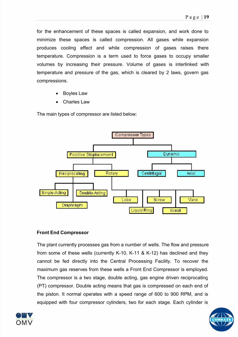
8102019 Gas sweetening Plant
httpslidepdfcomreaderfullgas-sweetening-plant 2362
P a g e | 19
for the enhancement of these spaces is called expansion and work done to
minimize these spaces is called compression All gases while expansion
produces cooling effect and while compression of gases raises there
temperature Compression is a term used to force gases to occupy smaller
volumes by increasing their pressure Volume of gases is interlinked with
temperature and pressure of the gas which is cleared by 2 laws govern gas
compressions
Boyles Law
Charles Law
The main types of compressor are listed below
Front End Compressor
The plant currently processes gas from a number of wells The flow and pressure
from some of these wells (currently K-10 K-11 amp K-12) has declined and they
cannot be fed directly into the Central Processing Facility To recover the
maximum gas reserves from these wells a Front End Compressor is employed
The compressor is a two stage double acting gas engine driven reciprocating
(PT) compressor Double acting means that gas is compressed on each end of
the piston It normal operates with a speed range of 600 to 900 RPM and isequipped with four compressor cylinders two for each stage Each cylinder is
8102019 Gas sweetening Plant
httpslidepdfcomreaderfullgas-sweetening-plant 2462
P a g e | 20
also equipped with a variable volume head end pocket
In case of compressor emergency shutdown the production chokes and the
Upper Master Valves on the on line wells will close and operator will be notified in
central control room Sweet gas from gas distribution network is used to operate the
gas engine driver of the compressor package The detailed scheme of working is
shown in figure (page 22 )
PT Reciprocating Compressor
The mechanical cycle of piston tube reciprocating compressor comprises four
strokes the expansion stroke the intake stroke the compression stroke and the
discharge stroke
Expansion Stroke
As the piston moves back on the expansion stroke the chamber volume
increases and the pressure drop As the pressure drops the discharge valve
closes since there is greater pressure in the discharge line than in the chamber
Intake Stroke
As the piston moves back during the intake stroke the pressure decreases until it
is less than the pressure in the inlet line This higher intake pressure opens the
inlet valve and gas rushes into the cylinder equalizing the pressure there with
the intake pressure The compression chamber is now at or near the intake
pressure
Compression Stroke
The piston now starts the compression stroke by moving forward decreasing the
chamber volume and increasing the pressure The increased pressure is now
higher than the intake pressure causing the intake valve to close
Discharge Stroke
The piston continues to move to the left during the discharge stroke This creates
an increase in chamber pressure until it is greater than the discharge pressure
When this happens the Discharge valve opens and the compressed air from the
8102019 Gas sweetening Plant
httpslidepdfcomreaderfullgas-sweetening-plant 2562
P a g e | 21
cylinder goes into the discharge line The compression cycle is then repeated
from the stage
Compressor Capacity
The capacity of the compressor depends upon cylinder displacement That
displacement is simply the volume that the piston displaces (moves) as it travels
from one end of the cylinder to the other Capacity and displacement is equal to
the cross-sectional area of the cylinder times the length of the stroke
Lubrication and Cooling
Lubricating oil is circulated through the system by a gear pump which is chain
driven from the engine crank shaft The oil pump is mounted on the engine front
housing
The pump operates between 30 - 40 psig
8102019 Gas sweetening Plant
httpslidepdfcomreaderfullgas-sweetening-plant 2662
P a g e | 22
A circulating pump deliver cooling water to the water jackets in the cylinder block
flowing around the cylinder liners and is directed into the cylinder heads Each
cylinder head has water cooled exhaust elbows which outlet the water into the
water cooled exhausts From the end of engine the water flows to compressor
1st and 2nd stage cylinders and compressor lube oil cooler (LOwater heat
exchanger) The water from the compressor cylinder and lube oil cooler returns
to engine water cooled exhaust
Figure Flow diagram of Front End Compressor
8102019 Gas sweetening Plant
httpslidepdfcomreaderfullgas-sweetening-plant 2762
P a g e | 23
Centrifugal Compressor
Centrifugal compressors are machines in which velocity and pressure given to air
or gas in a radial direction by one or more impellers diffuser combination In a
centrifugal compressor the mechanical energy is increased by centrifugal action
The gas enters the suction eye of a high speed rotary element called the impeller
which carries radial vanes integrally cast in it As the impeller rotates the blades
of the impeller force the gas outward from the center the impeller to the outer rim
of impeller the increase in velocity of the gas creates a flow pressure area at the
eye of the impeller The gas at the outer rim of the impeller is forced in to a
passage way called a diffuser where the velocity decreases in the pressure of the
gas
Inlet
The inlet to a centrifugal compressor is typically a simple pipe It may include
features such as a valve and both pressure and temperature instrumentation
Centrifugal impeller
The key component that makes a compressor centrifugal is the centrifugal
impeller shown above It is the impellers rotating set of vanes (or blades) that
gradually raises the energy of the working gas This is identical to an axial
compressor with the exception that the gases can reach higher velocities and
energy levels through the impellers increasing radius
8102019 Gas sweetening Plant
httpslidepdfcomreaderfullgas-sweetening-plant 2862
P a g e | 24
Diffuser
The next key component to the simple centrifugal compressor is the diffuser
Downstream of the impeller in the flow path it is the diffusers responsibility to
convert the kinetic energy (high velocity) of the gas into pressure by gradually
slowing (diffusing) the gas velocity
SEPERATORS
A well-stream is a mixture of gases hydrocarbon liquids water solids and
contaminants Due to variations in pressure and temperature gases evolve from
the liquids water vapor condenses and some of the well-stream changes to liquid
and free gas The separation of well-stream fluids takes place in a separator This
pressure vessel is manufactured in three forms
1 horizontal
2 vertical
3 spherical
To help separation the vessel is normally designed with a series of internal
fittings These fittings are built into the separator to ensure total phase separation
of the well-stream
In gas plants separators are given alternative names due to the function they
perform in the process system A scrubber does a similar job to a knockout drum
However the scrubber usually separates a stream containing high gas-to-liquid
ratios The knockout drum is used where a high degree of liquids are entrained in
the gas
Fluid flow from a well can include gas condensable liquid vapors water water
vapor crude oil and solids As well-stream fluids reach ground level where
pressure is lower than in the reservoir the capacity of the liquid to hold gas in
solution decreases and gas separates out of the oil
Separation depends upon the effect of gravity to separate liquids For adequate
separation one fluid must be lighter than the other fluid For example distillates
8102019 Gas sweetening Plant
httpslidepdfcomreaderfullgas-sweetening-plant 2962
P a g e | 25
(gasoline kerosene etc) and crude oil will not separate in a vessel because they
tend to dissolve in each other Because a separator basically depends upon
gravity to separate the fluids the ease with which separation takes place
depends upon the difference in density of the fluids
Droplets of liquid will separate from gas provided
a) The gas remains in the separator long enough
b) The gas flow remains constant to provoke separation
The difference in density between a gas and liquid will therefore determine the
maximum flow rate of liquid in the vessel
Figure Two phase horizontal separator
Gas bubbles in the liquid will break out in some oil field applications in 30 to 60
seconds Consequently the separator is designed so that the liquid remains in
the vessel for 30 to 60 seconds The length of time that a liquid remains in the
vessel is called its residence time Residence time differs widely from field to field
depending upon viscosity and API Gravity
Another important factor which must be considered is temperature Generally a
decrease in operating temperature will increase the liquid recovery in a separator
8102019 Gas sweetening Plant
httpslidepdfcomreaderfullgas-sweetening-plant 3062
P a g e | 26
as the gas condenses By reducing the pressure on the fluid flash separation
occurs resulting in a flow through the separator which is controlled by external
instrumentation
COALESCENCE
Another important principle in fluid separation is that of coalescence This means
the coming together of liquid droplets created by the force of gravity
A common example of coalescing occurs when drops of water form on the
windshield of a car as it is driven in fog As the tiny drops or water which make up
the fog strike the windshield they combine and eventually form a drop large
enough to run down the glass
Several of the internal devices of a separator such as deflector plates
straightening vanes and even the vessel walls are forms of coalescers In each
vessel drops of liquid adhere to the surface of the device and combine with other
8102019 Gas sweetening Plant
httpslidepdfcomreaderfullgas-sweetening-plant 3162
P a g e | 27
drops until the drop is large enough to fall out The effectiveness of separation
will also depend upon the total amount of coalescing surface area that is present
There are many different types of separators used in the Oil amp Gas industry
Consequently separators are manufactured with one two or several internal
fittings depending on their use and quick removal of these fluids from the vessel
DEFLECTOR PLATES
These are fitted in front of the inlet to the separator and can be net or
dish-shaped Their purpose is to absorb the impact of the incoming fluids and to
encourage the separation of gas and liquids They also slow the flow rate of the
liquids through the vessel
WEIRS
A weir is a metal wall which is fitted across the inside of the vessel normally to a
height of 50 of the overall height of the separator Its purpose is to assist the
process of three phase separation The inlet fluids (oil plus water) are given time
to separate in the liquid accumulation section The water level (interface) is
normally controlled at 50 of the height of the weir Oil floating on the wateroverflows the weir and accumulates in the small oil compartment where it is
drawn off under level control
CENTRIFUGAL DEVICES
These are used in both vertical and horizontal separators for gas-liquid
separation The device imparts a swirling motion to the fluids entering the vessel
Centrifugal force causes the heavier liquids to travel outwards towards the walls
of the vessel and the lighter gases to flow up the centre Centrifugal devices are
also known as cyclones
VORTEX BREAKERS
When liquid flows through a drain outlet a vortex (whirlpool) will form This can
be seen when we pull the plug from a sink or bath tub The same would happen
as water and oil flow from the separator This condition a vortex could allow gas
to flow down the centre of the whirlpool and enter the liquid phase causing
8102019 Gas sweetening Plant
httpslidepdfcomreaderfullgas-sweetening-plant 3262
P a g e | 28
pressurizing of tanks etc To stop this happening vortex breakers are fitted to all
liquid outlets Although they come in a number of different designs vortex
breakers all serve the same purpose - to prevent a whirlpool from forming
MIST OR DEMISTER PADS
The gas which is released from the fluids in the separator still contains droplets of
oil and water which coalesce and fall when the drops get large enough The
demister pad assists in this process Made from knitted wire and contained within
a sturdy frame it causes the gas to continually change its direction of flow
Because gas changes direction far easier than liquid the gas will flow around
each strand of wire whilst the liquid entrained in the gas stream will continue and
stick to the wire
COALESCING PLATES
There are several different forms of coalescing devices the most common of
which are coalescing plates These plates are mounted in the flow stream of the
fluids and assist in breaking down oil-water emulsions The fluid is forced to
follow a path that constantly changes direction This causes the water droplets to
gather together or coalesce and fall to the bottom of the separator The same
principle is used to separate gas and oil mixtures when the oil droplets are
induced to coalesce Simply stated every surface within the separator including
the separator walls assists with the coalescing process
STRAIGHTENlNG VANES
These are often fitted to horizontal separators to remove turbulence in the gas
stream after initial separation at the inlet deflector
FLOAT SHEILD
Internal floats are used as level controllers Any agitation of the liquid surface or
the effect of coalesced liquids falling on the float may cause control problems
Therefore a float shield is fitted to enclose the float creating an area of still liquid
8102019 Gas sweetening Plant
httpslidepdfcomreaderfullgas-sweetening-plant 3362
P a g e | 29
MEMBRANES
The gas contains 12 carbon dioxide and 22 ppm of hydrogen sulphide at 115oF
and 1100 psig This needs to be removed before the gas can be exported The
majority of carbon dioxide hydrogen sulphide and water is removed by means of
membranes
Membranes are thin semipermeable barriers that selectively separate some
compounds from others Currently the only commercially workable membranes
used for CO2 removal are polymer based for example cellulose acetate
polyimides polyamides polysulfone polycarbonates and polyetherimide The
membrane does not operate as a filter where small molecules are separated
from larger ones through a medium with pores rather it separates based on how
well different compounds dissolve into the membrane and diffuse through it The
membranes are manufactured in flat sheets consisting of an extremely thin
nonporous layer mounted on a much-thicker and highly porous layer of the same
material providing mechanical strength The flat sheets are combined into a
spiral-wound element (Figure below) Feed gas enters along the side of the
membrane and passes through the feed spacers As the gas travels between
membrane sheets CO2 H2S and H2O permeate through the membrane and are
collected in the permeate tube The driving force for transport is the high-feed
pressure and low-permeate pressures The gas on the feed side that does not
permeate leaves through the side of the element opposite the feed position Once
the membranes have been manufactured into elements six to 12 elements are
joined together and inserted into a tube Multiple tubes are mounted on skids in a
horizontal orientation
8102019 Gas sweetening Plant
httpslidepdfcomreaderfullgas-sweetening-plant 3462
P a g e | 30
Figure Membrane general Working
In high H2S applications most polymers have been shown to have very little
resistance to H2S plasticization (ldquosofteningrdquo of the membrane) and as a
consequence can only be used at very low H2S partial pressure limits Cellulose
acetate membranes in contrast have been shown to be applicable at extreme
H2S partial pressure conditions It is these membranes that have been utilized in
the testing to determine the limits of membrane performance in high H 2S
applications
The primary membranes used in Kadanwari facility are Cellulose acetate
Cellulose acetic acid and acetic anhydride are mixed together and reacted to
form cellulose acetate polymers This process is aided by the addition of a small
amount of sulfuric acid which is subsequently neutralized during processing
However the membranes are bought from UOP (vendor) and installed for use
8102019 Gas sweetening Plant
httpslidepdfcomreaderfullgas-sweetening-plant 3562
P a g e | 31
How membrane work
The basic principle of separation is selectivity of certain components of a mixture
for the membrane For example the cellulose acetate membrane has very high
selectivity for CO2 and H2S as compared to CH4 Therefore such type of
membrane can be used in gas sweetening process
The selectivity is directly related to the Permeability of gas which accounts that
which gas can pass across the membrane more easily In simple words
membranes being polymer materials are made of long chains of molecules The
different structure of polymer materials only allow selective molecules to pass
through them depending upon chemical and physical compatibility Thus
permeability depends upon choice of polymer
The permeability is determined by permeability coefficient (P) and is product of
solubility (S) and diffusivity (D)
P = S D
Solubility
The solubility is mainly determined by ease of condensation Heavy molecules
are more readily condensed Therefore higher molecular weighted molecules will
more easily condensed and therefore have greater solubility
Molecule Molecular weight
CH4 16
H2S 34
CO2 44
8102019 Gas sweetening Plant
httpslidepdfcomreaderfullgas-sweetening-plant 3662
P a g e | 32
Diffusivity
Diffusivity is ease of molecule to penetrate into some material It depends on size
of gas molecule Here size of molecule is not to be confused by molecular weight
it is the size of the structure Eg the size of O2 molecule is smaller than N2
Molecule Molecular Diameter (Ao)
CO2 33
H2S 36
Ch4 40
For cellulose acetate
DCO2DCH4 S CO2S CH4 P CO2P CH4
45 73 308
Chemical degradation
Cellulose acetate polymer is chemically degraded by a process called hydrolysis
which means breaking apart by the addition of water This is a chemical reaction
in which water is added to the cellulose acetate polymer causing the release of
acetic acid molecules This process proceeds stepwise until all the acetate
groups are released resulting in the reformation of cellulose Moreover alcohols
aromatic hydrocarbons or solvents with chlorine nitro benzene or similar
aromatic solvents will harm the membrane It will expand and lose plastification in
contact with them
Effect of Temperature
The permeation rates of all gases increases with increasing temperature
however membrane selectivity for CO2 over hydrocarbon decreases at higher
8102019 Gas sweetening Plant
httpslidepdfcomreaderfullgas-sweetening-plant 3762
P a g e | 33
temperature Consequently CO2 removal will improve as operating temperature
increases but hydro carbon recovery will decrease
Primary Membrane
The primary membranes comprise of two trains Each train consists of two
sections AB and CD each section consists of a 30 tube membrane skid (A and
C) followed by a 25 tube skid (B and D) The conditioned gas (after pre-
treatment) enters the primary membrane via the particulate filter adjacent to the
skid The gas is fed to the membranes through a common inlet manifold which
supplies primary membranes skids A and C A pressure control loop located
upstream of the manual inlet isolation valve is provided to maintain a constant
supply pressure to the membrane skid and to allow for preheating at the inlet
prior to skid start-up This pressure control loop can also be used during start-up
to control the pressurization of the pretreatment skid and associated pipes to the
primary membranes
The gas passes through membrane skid A the residual gas exiting the membrane
skid is sent to skid B and the permeate to common permeate discharge header An
identical arrangement is provide on the inlet to skid C as provided on skid A Theresidual gas from skid B combines with the residual gas from skid D in a common
discharge header and is then sent to the H2S polishing towers via the feed coolers
on the pre-treatment skid The permeate from skid B is sent to the common
permeate discharge header The permeate discharge header sends the gas to
either the recycle compressor or the vent header via a pressure control loop
Overpressure protection for the membranes is provided by a pressure safety valve
on the supply header to the membrane banks
8102019 Gas sweetening Plant
httpslidepdfcomreaderfullgas-sweetening-plant 3862
P a g e | 34
Secondary (Recycle) Membrane
The recycle membranes comprise of a single train with two skids each with four
banks of membrane tubes The conditioned gas from the discharge of the recycle
pre-treatment skid is routed to the first recycle membrane skid The gas passes
through the membranes the residual gas is fed to primary membrane (skid A) inlet
via feed gas cooler and permeate to the common permeate discharge header An
identical arrangement is provide on the inlet to skid B Permeate from the recycle
membrane skids A and B is routed to the vent header Some portion of permeate is
heated and sent for regeneration in Mem-Guard units Nitrogen purge can be
connected downstream of the inlet isolation valve on each skid to enable the
membrane tubes to be purged and left pressurized during prolonged shutdown
8102019 Gas sweetening Plant
httpslidepdfcomreaderfullgas-sweetening-plant 3962
P a g e | 35
Figure Flow Diagram of Recycle membrane unit
8102019 Gas sweetening Plant
httpslidepdfcomreaderfullgas-sweetening-plant 4062
P a g e | 36
ADVANTAGES OF MEMBRANE SYSTEMS
Membrane systems have major advantages over more-traditional methods of
acid gas removal
Lower capital cost Membrane systems are skid mounted and so the
scope cost and time taken for site preparation are minimal Installation
costs are significantly lower than alternative technologies especially for
remote areas Furthermore no additional facilities for solvent storage and
water treatment needed by other processes are required
Lower operating costs The only major operating cost for single-stage
membrane systems is membrane replacement This cost is significantly
lower than the solvent replacement and energy costs associated with
traditional technologies The improvements in membrane and
pretreatment design allow a longer useful membrane life which further
reduces operating costs The energy costs of multistage systems with
large recycle compressors are usually comparable to those for traditionaltechnologies
Deferred capital investment Often contracted sales-gas flow rates
increase over time as more wells are brought on-line With traditional
technologies the system design needs to take this later production into
account immediately and so the majority of the equipment is installed
before it is even needed The modular nature of membrane systems
means that only the membranes that are needed at start-up need be
installed The rest can be added either into existing tubes or in new skids
only when they are required
Operational simplicity and high reliability Because single-stage
membrane systems have no moving parts they have almost no
8102019 Gas sweetening Plant
httpslidepdfcomreaderfullgas-sweetening-plant 4162
P a g e | 37
unscheduled downtime and are extremely simple to operate They can
operate unattended for long periods of time The addition of a recycle
compressor adds some complexity to the system but still much less than
with a solvent- or adsorbent-based technology Multistage systems can be
operated at full capacity as single-stage systems when the recycle
compressor is down
Good weight and space efficiency Skid construction can be optimized
to the space available This space efficiency is especially important for
offshore environments where deck area is at a premium and is the
reason why so many new offshore developments have chosen to use
membranes for acid gas removal Figure 6 illustrates the space efficiency
of membrane systems The membrane unit in the lower left corner
replaced all the amine and glycol plant equipment shown in the rest of the
picture
Adaptability Because membrane area is dictated by the percentage of
acid gas removal rather than absolute acid gas removal small variations
in feed acid gas content hardly change the sales-gas acid gas
specification For example a system designed for 10 down to 3 acid
gas removal produces a 35 product from a 12 feed gas and a 5
product from a 15 feed gas
Design efficiency The membrane and pretreatment systems integrate a
number of operations such as dehydration CO2 and H2S removal dew-
point control and mercury removal Traditional acid gas removal
technologies require all of these operations as separate processes and
may also require additional dehydration because some technologies
saturate the product stream with water
8102019 Gas sweetening Plant
httpslidepdfcomreaderfullgas-sweetening-plant 4262
P a g e | 38
Power generation The permeate gas from membrane systems can be
used to provide fuel gas for power generation either for a recycle
compressor or other equipment
Ideal for debottlenecking Because expanding solvent- or adsorbent-
based acid gas removal plants without adding additional trains is difficult
an ideal solution is to use membranes for bulk acid gas removal and leave
the existing plant for final cleanup An additional advantage is that the
permeate gas from the membrane system can often be used as fuel for
the existing plant thus avoiding significant increase in hydrocarbon
losses
Environmentally friendly Membrane systems do not involve the
periodic removal and handling of spent solvents or adsorbents Permeate
gases can be flared used as fuel or re-injected into the well Items thatdo need disposal such as spent membrane elements can be incinerated
Ideal for remote locations Many of the factors mentioned above make
membrane systems a highly desirable technology for remote locations
where spare parts are rare and labor unskilled Furthermore solvents
storage and trucking water supply power generation or extensive
infrastructure are not required
Re-injection optimizations Since the permeate stream from the
membrane system can be operated at elevated pressures it is possible to
further pressurize by re-injection compression train
8102019 Gas sweetening Plant
httpslidepdfcomreaderfullgas-sweetening-plant 4362
P a g e | 39
Sorption
Sorption is a physical and chemical process by which one substance becomes
attached to another
It is of two main types
1 Absorption
2 Adsorption
Absorption
Absorption is a physical or chemical phenomenon or process in which atoms
molecules or ions enter some bulk phase ndash gas liquid or solid material This is a
different process from adsorption since molecules undergoing absorption are
taken up by the volume not by the surface (as in the case for adsorption)
Absorption process may be chemical (reactive) or physical (non-reactive)
Physical absorption
Physical absorption or non-reactive absorption is made between two phases ofmatter a liquid absorbs a gas or a solid absorbs a liquid
When a liquid solvent absorbs a gas mixture or part of it a mass of gas moves
into the liquid For example water may absorb oxygen from the air This mass
transfer takes place at the interface between the liquid and the gas at a rate
depending on both the gas and the liquid This type of absorption depends on the
solubility of gases the pressure and the temperature The rate and amount of
absorption also depend on the surface area of the interface and its duration in
time
When a solid absorbs a liquid mixture or part of it a mass of liquid moves into the
solid For example a clay pot used to store water may absorb some of the water
This mass transfer takes place at the interface between the solid and the liquid
at a rate depending on both the solid and the liquid
8102019 Gas sweetening Plant
httpslidepdfcomreaderfullgas-sweetening-plant 4462
P a g e | 40
Chemical absorption
Chemical absorption or reactive absorption is a chemical reaction between the
absorbed and the absorbing substances Sometimes it combines with physical
absorption This type of absorption depends upon the stoichiometry of the
reaction and the concentration of its reactants
Adsorption
Adsorption is the adhesion of atoms ions or molecules from a gas liquid or
dissolved solid to a surface This process creates a film of the adsorbate on the
surface of the adsorbent The binding to the surface is usually weak and
reversible Compounds with color and those that have taste or odor tend to bind
strongly Compounds that vibrate at frequencies in the visible spectrum are very
often are strongly adsorbed on activated carbon
The most common industrial adsorbents are activated carbon silica gel and
alumina because they present enormous surface areas per unit weight
Depending on the nature of attractive forces existing between the adsorbate and
adsorbent adsorption can be classified as
i) Physical adsorption
ii) Chemical adsorption
i) Physical adsorption (Physisorption)
In physical adsorption the forces of attraction between the molecules of the
adsorbate and the adsorbent are of the weak van der Waals type Since the
forces of attraction are weak the process of physisorption can be easily reversed
by heating or decreasing the pressure of the adsorbate (as in the case of gases)
8102019 Gas sweetening Plant
httpslidepdfcomreaderfullgas-sweetening-plant 4562
P a g e | 41
ii) Chemical adsorption (Chemisorption)
In chemisorption the forces of attraction between the adsorbate and the
adsorbent are very strong the molecules of adsorbate form chemical bonds with
the molecules of the adsorbent present in the surface
Adsorption is generally accompanied by release of energy that is most
adsorption processes are exothermic in nature Adsorption is a spontaneous
process therefore its free energy change is negative (∆Glt0) However the
entropy change associated with adsorption is generally negative because the
adsorbate molecules lose their translation freedom when they get attached to the
surface of the adsorbent Therefore in order for ∆G to be negative the enthalpy
change (∆H) must be sufficiently negative such that (∆G=∆H-T∆S) lt 0 This
explanation accounts for exothermic adsorption processes In cases where
endothermic adsorption occurs the entropy change ∆S is sufficiently positive
such that ∆G remains negative
Pre treatment
The main function of pretreatment skid is to provide membrane inlet specification
gas as mentioned by the vendor UOP It removes the contaminants that would
poison the membranes like dust solids (adsorbent particles) lube oil heavy
hydrocarbons etc It consists of
Feed Cooler
Feed Gas Scrubber
Filter Coalescer
Feed Gas Heater
Activated Carbon Guard Filter
Particle Filter
8102019 Gas sweetening Plant
httpslidepdfcomreaderfullgas-sweetening-plant 4662
8102019 Gas sweetening Plant
httpslidepdfcomreaderfullgas-sweetening-plant 4762
P a g e | 43
The regeneration is carried out by heated permeate gas from the recycle
membranes at 450oF The vessel is depressurized to 20 psi and heated gas is
introduced from top The gas carries out the adsorbed contaminants and leaves
the vessel from bottom cleaning the adsorbent This contaminated gas is burnt in
the flare
UOP the vendor of Memguard unit has never disclosed that what substance
MG3 and MG5 exactly are But as mentioned by vendor that both care class of
aluminosilicates Therefore MG3 can be potassium aluminosilicate and MG5 can
be Calcium aluminosilicate These are molecular sieves adsorbents Molecular
sieves are a microporous material which can selectively adsorb gases andliquids They are synthetic zeolites (crystalline metal aluminosilicates) which
upon dehydration can efficiently and selectively remove water or other
solvents The selectivity of a molecular sieve is determined by its pore size
molecules with a critical diameter which is less than the pore size will be
efficiently adsorbed while larger molecules will be excluded
8102019 Gas sweetening Plant
httpslidepdfcomreaderfullgas-sweetening-plant 4862
P a g e | 44
3A Molecular Sieve Adsorbent
The 3A molecular sieve adsorbent has a 3 angstrom (3A) pore size which means
that any molecule that is larger than the 3 angstrom pores will not be adsorbed
The 3A molecular sieve is the potassium type of A crystalline structure and is a
form of alkali Aluminosilicate For a 3A molecular sieve the sequence rate that
adsorption occurs is He Ne N and H2O
Due to the crystalline structure molecular sieves that have a 3 angstrom pore
size have a very high rate of adsorption and properties that promote a longer life
for products treated by the sieve The most common use for the 3A molecular
sieve is to remove water and moisture from materials that are in gas and liquid
form
5A Molecular Sieve Adsorbent
These are molecular sieve adsorbents with a pore size of 5 angstrom (5A) 5A
molecular sieves are unable to adsorb any molecules or impurities that are
smaller than 5A It is calcium form of type A crystalline structure and is form of analkali-aluminosilicate that is most commonly used to separate isomerous alkanes
from normal alkanes and to co-adsorb moisture and water along with carbon
dioxide from gases In additional 5A molecular sieves are used for gaseous
pressure swing adsorption (PSA)mdashthat is to separate particular gases from other
gases
Adsorption of nC4H10
Adsorption of nC4H10
Adsorption of C3H8 to C22H46
Adsorption of Freon-12 (dichlorodifluoromethane)
Natural gas drying
Normal- and iso-paraffin separation
Separation of aromatic
8102019 Gas sweetening Plant
httpslidepdfcomreaderfullgas-sweetening-plant 4962
P a g e | 45
Inlet Composition of Memguard vessel
COMPSOSITION MOLE
CARBON DIOXIDE 1096
MEHTANE 8593
ETHANE 173
PROPANE 023
I-BUTANE 008
N BUTANE 004
PENTANES 004
HEXANE + 000
NITROGEN 076
WATER 007
Outlet Composition of Memguard vessel
COMPSOSITION MOLE
CARBON DIOXIDE 1098
MEHTANE 8608
ETHANE 173
PROPANE 023
I-BUTANE 008N BUTANE 004
PENTANES 004
HEXANE + 000
NITROGENT 076
WATER 000
H2S polisher
The H2S polishing unit has been designed to treat 187 MMscfday of natural gas
containing up to 11 CO2 and 21 ppm H2S where the level of the CO2 and H2S
is reduced using a MemGuard Membrane separation unit The unit is situated
down-stream of the membrane unit and will further reduce the level of H2S in the
processed gas to a sales gas specification of 38 ppm
8102019 Gas sweetening Plant
httpslidepdfcomreaderfullgas-sweetening-plant 5062
P a g e | 46
This process uses three non-regenerable fixed bed absorber vessels using a low
temperature high activity absorbent The absorbent is a mixture of activated
metal oxides (mainly zinc oxide) The three towers can are generally operated in
parallel arrangement but on demand can be used in series (any of alternate
arrangements of A B C vessels) as shown in figure
The higher sales gas flow rate increased the catalyst consumption and
replacement frequency
ZnO + H2S =gt ZnS + H20
Routine samples are taken from the beds to provide a check on each bed
performance and to follow the saturation profile during the absorbent life After
the adsorbent has been fully utilized the adsorption vessels are recharged with
new adsorbent discarding the utilized one in a safe manner
109oF
1215 psig
Before H2S Polishing After H2S Polishing
8102019 Gas sweetening Plant
httpslidepdfcomreaderfullgas-sweetening-plant 5162
P a g e | 47
Figure
H2S Tower
Inlet pipe
4 Drums of 19mm
ceramic Balls
6 Micron mesh
5 Drums of 50mmceramic
1 Drums of19mm ceramic
01 Drums of6mm ceramic
112 drums of
Catalist ZnO
8102019 Gas sweetening Plant
httpslidepdfcomreaderfullgas-sweetening-plant 5262
P a g e | 48
Recycle Compressor
The permeate gas of the primary membrane unit carries recoverable amount of
CH4 It is fed to recycle membrane unit for further CH 4 recovery But the
permeate pressure from primary membranes which has been reduced to 12 psi
must be regenerated to 1200 psi for the gas to be fed again to the system For
this purpose we have employed recycle compressor The compressor is a four
stage centrifugal compressor It is driven by gas turbine of 31200 HP It has 25
MW producing capacity
Figure Recycle Compressor Process Flow Diagram
8102019 Gas sweetening Plant
httpslidepdfcomreaderfullgas-sweetening-plant 5362
P a g e | 49
Sales Gas Compressor
Gas from H2S polishing unit is sent to sales gas compressor where its pressure
is enhanced to 1100 psi so it may be injected to SNGPL high pressure trunk line
Sales gas compressor is single stage gas turbine driven
Figure Process Flow of Sales Gas Compressor
8102019 Gas sweetening Plant
httpslidepdfcomreaderfullgas-sweetening-plant 5462
P a g e | 50
Cooling Towers
A cooling tower is a heat rejection device which extracts waste heat to theatmosphere through the cooling of a water stream to a lower temperature Hot
water from the system enters the cooling tower and is distributed over the fill
(heat transfer surface) Air is induced or forced through the fill causing a small
portion of the water to evaporate This evaporation removes heat from the
remaining water which is collected in the cold water basin and returned to the
system to absorb more heat Each cooling tower line although operating under
the same basic principle of operation is arranged a little differently
Types
Natural draft mdash Utilizes buoyancy via a tall chimney Warm moist air naturally
rises due to the density differential compared to the dry cooler outside air Warm
moist air is less dense than drier air at the same pressure This moist air
buoyancy produces an upwards current of air through the tower
Mechanical draft mdash Uses power-driven fan motors to force or draw airthrough the tower
o Induced draft mdash A mechanical draft tower with a fan at the
discharge (at the top) which pulls air up through the tower The fan
induces hot moist air out the discharge This produces low entering
and high exiting air velocities reducing the possibility of
recirculation in which discharged air flows back into the air intake
o Forced draft mdash A mechanical draft tower with a blower type fan at
the intake The fan forces air into the tower creating high entering
and low exiting air velocities The low exiting velocity is much more
susceptible to recirculation This fanfill geometry is also known as
blow-through
8102019 Gas sweetening Plant
httpslidepdfcomreaderfullgas-sweetening-plant 5562
P a g e | 51
Forced Draft Cooling Tower Vs Induced Draft Cooling Tower
Induced Draft Cooling Tower have the ability to handle large water flow
rate than Forced Draft Cooling Tower
Induced Draft Cooling Tower is suitable for large cell sizes and fan sizes
as compared with Forced Draft Larger fan size may result in greater
efficiency and consequently lower power and sound level
Forced Draft Cooling Tower can be square or rectangular type only
however Induced Draft Cooling Towers can be round square or
rectangular type
Induced Draft Cooling Tower uses more compact ground area than Forced
Draft Cooling Tower equivalent capacity due to absence of fan on one
side
Fan equipment is warm exhaust air is less liable to icing up in winter
operation (Cold Countries)
Higher velocity in Forced Draft Cooling Tower cause drop in suspension
and cause additional static resistance to system
Configuration
There are two main configurations of factory assembled cooling towers crossflow
and counterflow In crossflow cooling towers the water flows vertically down the
fill as air flows horizontally across In counterflow cooling towers the water flows
vertically down the fill as air flows vertically up
Crossflow Configuration Counterflow Configuration
8102019 Gas sweetening Plant
httpslidepdfcomreaderfullgas-sweetening-plant 5662
P a g e | 52
Drift mdash Water droplets that are carried out of the cooling tower with the exhaust
air Drift droplets have the same concentration of impurities as the water entering
the tower The drift rate is typically reduced by employing baffle-like devices
called drift eliminators through which the air must travel after leaving the fill and
spray zones of the tower
Blow-out mdash Water droplets blown out of the cooling tower by wind generally at
the air inlet openings Water may also be lost in the absence of wind through
splashing or misting Devices such as wind screens louvers splash deflectors
and water diverters are used to limit these losses
Blow-down mdash The portion of the circulating water flow that is removed (usually
discharged to a drain) in order to maintain the amount of Total Dissolved Solids
(TDS) and other impurities at an acceptably low level Higher TDS concentration
in solution may result from greater cooling tower efficiency However the higher
the TDS concentration the greater the risk of scale biological growth and
corrosion
Make-up mdash The water that must be added to the circulating water system in
order to compensate for water losses such as evaporation drift loss blow-out
blow-down etc
Approach mdash The approach is the difference in temperature between the cooled-
water temperature and the entering-air wet bulb temperature
Range mdash The range is the temperature difference between the warm water inlet
and cooled water exit
Fill mdash Inside the tower fills are added to increase contact surface as well as
contact time between air and water to provide better heat transfer The efficiency
of the tower depends on the selection and amount of fill
8102019 Gas sweetening Plant
httpslidepdfcomreaderfullgas-sweetening-plant 5762
P a g e | 53
There are two types of fills that may be used
o Film type fill (causes water to spread into a thin film)
o Splash type fill (breaks up falling stream of water and interrupts its
vertical progress)
Important
Scale build up is controlled by adding chemicals to the cooling loop and diluting
the concentration by blow down and make-up Following chemicals are added to
the Cooling to control CorrosionSale and microbial growth
Corrosion Inhibitor To control corrosion in the Cooling system
Dispersant To kept ions in suspension to avoid settle down and buildup
Sodium hypo Chlorite To Control microbial Growth
Acid To control Alkalinity in the system
High Stress Polymer To run the system at higher conductivity It is a
multifunctional polymer for Zinc amp Phosphate stabilization in cooling tower
Fin Fan Cooler
Fin fan heat exchanger is simply a pressure vessel which cools a circulating fluid
within finned tubes by forcing ambient air over the exterior of the tubes A
common example of an air cooler is a carrsquos radiator Fin Fan Coolers are used in
any application where large quantities of heat need to be transferred This
includes chemical and petrochemical industries power stations waste-to-energy
facilities as well as steelworks
Fin Fan Cooler are used for two primary reasons
They increase plant efficiency
They are a green solution as compared to cooling towers and shell and
tube heat exchangers because they do not require an auxiliary water
8102019 Gas sweetening Plant
httpslidepdfcomreaderfullgas-sweetening-plant 5862
P a g e | 54
supply (water lost due to drift and evaporation plus no water treatment
chemicals are required)
Figure General Overview of Fin Fan Cooler
Produced Water
The produced water system receives liquid from the equipment Miano slug
catcher train 1 and 2 inlet separators and is fed to three phase separator where
water oil and gas is separated The gases produced are burnt in incinerator
whereas hydrocarbon liquid is stored to be sold Liquid from compressors
recycle inlet separator recycle feed scrubber high and low pressure slug
catchers is passed to degasser Separated water is injected down the earth
Incinerator
The term incinerate means to burn something until nothing is left but ashes An
incinerator is a unit or facility used to burn trash and other types of waste until it is
reduced to ash An incinerator is constructed of heavy well-insulated materials
so that it does not give off extreme amounts of external heat The high levels of
heat are kept inside the furnace or unit so that the waste is burned quickly and
efficiently If the heat were allowed to escape the waste would not burn as
completely or as rapidly
8102019 Gas sweetening Plant
httpslidepdfcomreaderfullgas-sweetening-plant 5962
P a g e | 55
Control System
The plant is controlled at CCR (Central Control Room) by PLCs (Programmable
Logic Controllers) through fiber optic control line All control parameters are
received at LER (Local Equipment Room) via two optic fiber control lines One
being primary and other secondary operating in redundancy ie if primary fails
control shifts to secondary These control parameters are sent to CCR via single
optic fiber cable
Safety System
Wellheads and Gas Processing Plant have their own Fire amp Gas detection
systems emergency shutdown (ESD) Plant has a fault tolerant controller It is
based on Triple Modular Redundant (TMR) architecture manufactured by
Triconex The TMR system is based on three isolated parallel control systems
integrated into one system The system operates on a two out of three voting
principle which provides high integrity error free uninterrupted operation with no
single point of failure The TMR receives inputs from Process Sensors Manual
Switches Fire amp Gas Detectors Packaged Equipment Control Systems and
Product Exporting Facilities The TMR carries out cause and effect processing on
the data received and where necessary produces output signals Outputs from
the TMR are hard wired directly to ESD shutdown and blow down valve
solenoids motor control instrumentelectrical interfaces to control electrical
drives package equipment logic control systems manifold area as well as
telecoms
The operator in central control room is able to accept alarms and once the fault
has been cleared reset the input All the control systems are centralized to a
single interface All the PLCs (Programmable Logic Controllers) communicate with
the servers and servers communicate with the clients through Ethernet connectivity
Centralization eases the navigation of different systems at a common interface
Emergency Shutdown
The ESD system receives inputs from field mounted instrumentation on the process
8102019 Gas sweetening Plant
httpslidepdfcomreaderfullgas-sweetening-plant 6062
P a g e | 56
and utility equipment and initiates executive actions appropriate to the level of ESD
The system is an Active system which is in standby and will activate when in an
alarm or fault condition The Kadanwari Gas Process Facility ESD system is
comprised of five (5) levels The emergency severity decreases with increasing ESD
level number
ESD 1
This shutdown level is automatically initiated by fire major gas leak or a detected
toxic atmosphere in the process area of the plant or manually from CCR A level 1
shutdown will cause all production to cease close all emergency shutdown
valves stop the process and shutdown of the main power generation The
emergency vent valves to the stack will open and in addition all equipment of zone 1
certified will be isolated This is the highest level of ESD and will cause the following
to occur
All Shutdown Valves (SDVs) on the process facility will close All slowdown Valves (BDVs) on the process facility will open
All Main Gas Driven Generators will be tripped
Emergency Diesel Generator will start
All electrical power to process and utility rotating equipment will be
isolated
Wellhead Choke Valves Close Wing Valves Close Upper Master Valve
(UMV) Close
ESD 2
This shutdown level is activated automatically if a major process or utility failure
occurs or manually from CCR All production to the plant from the wellhead is
stopped All emergency shutdown valves trip to their fail safe position
Venting shall be as specified This level of ESD will cause the following to occur
8102019 Gas sweetening Plant
httpslidepdfcomreaderfullgas-sweetening-plant 6162
P a g e | 57
All Shutdown Valves (SDVs) on the process facility will close
All electrical power to process and utility rotating equipment will be
isolated
Wellhead Choke Valve Close Wing Valves Close and Upper Master Valve(UMV) Close
ESD 3
The level 3 shutdown isolates and stops a single process train only Production
continues via the other train This ESD level is initiated by process conditions or
operator at local panel This level of ESD will cause the following to occur
ESD 3A Train 1 production to cease
ESD 3B Train 2 production to cease
All online wellhead choke valves go to minimum flow ie (1O )
ESD 4
A level 4 shutdown shall cease all production from an entire field either
Kadanwari or Miano upstream of the associated slug catchers ESD 4K for
Kadanwari amp ESD 4M for Miano This ESD level is initiated automatically by slug
catcher abnormal process conditions This level of ESD will cause the following
to occur
All SDVs close isolating the relevant slug catcher and its upstream gas
production facility from the Kadanwari Gas Processing Plant
All Wellhead Choke Valves Close Wing Valves Close and Upper MasterValves (UMV) of the relevant gas production facility Close
A parallel timer is provided to close within 10 second if not closed in given
time SSSV seals the well
ESD 5
A level 5 shutdown represents equipment shutdown for the protection of the
individual equipment without any change in the process This level of ESD is for the
protection of various pieces of equipment and is initiated by its own inputs eg
8102019 Gas sweetening Plant
httpslidepdfcomreaderfullgas-sweetening-plant 6262
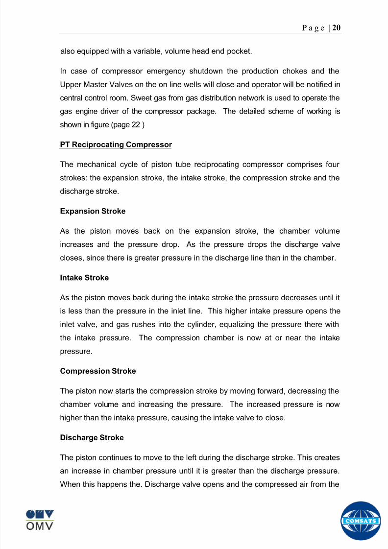
8102019 Gas sweetening Plant
httpslidepdfcomreaderfullgas-sweetening-plant 2462
P a g e | 20
also equipped with a variable volume head end pocket
In case of compressor emergency shutdown the production chokes and the
Upper Master Valves on the on line wells will close and operator will be notified in
central control room Sweet gas from gas distribution network is used to operate the
gas engine driver of the compressor package The detailed scheme of working is
shown in figure (page 22 )
PT Reciprocating Compressor
The mechanical cycle of piston tube reciprocating compressor comprises four
strokes the expansion stroke the intake stroke the compression stroke and the
discharge stroke
Expansion Stroke
As the piston moves back on the expansion stroke the chamber volume
increases and the pressure drop As the pressure drops the discharge valve
closes since there is greater pressure in the discharge line than in the chamber
Intake Stroke
As the piston moves back during the intake stroke the pressure decreases until it
is less than the pressure in the inlet line This higher intake pressure opens the
inlet valve and gas rushes into the cylinder equalizing the pressure there with
the intake pressure The compression chamber is now at or near the intake
pressure
Compression Stroke
The piston now starts the compression stroke by moving forward decreasing the
chamber volume and increasing the pressure The increased pressure is now
higher than the intake pressure causing the intake valve to close
Discharge Stroke
The piston continues to move to the left during the discharge stroke This creates
an increase in chamber pressure until it is greater than the discharge pressure
When this happens the Discharge valve opens and the compressed air from the
8102019 Gas sweetening Plant
httpslidepdfcomreaderfullgas-sweetening-plant 2562
P a g e | 21
cylinder goes into the discharge line The compression cycle is then repeated
from the stage
Compressor Capacity
The capacity of the compressor depends upon cylinder displacement That
displacement is simply the volume that the piston displaces (moves) as it travels
from one end of the cylinder to the other Capacity and displacement is equal to
the cross-sectional area of the cylinder times the length of the stroke
Lubrication and Cooling
Lubricating oil is circulated through the system by a gear pump which is chain
driven from the engine crank shaft The oil pump is mounted on the engine front
housing
The pump operates between 30 - 40 psig
8102019 Gas sweetening Plant
httpslidepdfcomreaderfullgas-sweetening-plant 2662
P a g e | 22
A circulating pump deliver cooling water to the water jackets in the cylinder block
flowing around the cylinder liners and is directed into the cylinder heads Each
cylinder head has water cooled exhaust elbows which outlet the water into the
water cooled exhausts From the end of engine the water flows to compressor
1st and 2nd stage cylinders and compressor lube oil cooler (LOwater heat
exchanger) The water from the compressor cylinder and lube oil cooler returns
to engine water cooled exhaust
Figure Flow diagram of Front End Compressor
8102019 Gas sweetening Plant
httpslidepdfcomreaderfullgas-sweetening-plant 2762
P a g e | 23
Centrifugal Compressor
Centrifugal compressors are machines in which velocity and pressure given to air
or gas in a radial direction by one or more impellers diffuser combination In a
centrifugal compressor the mechanical energy is increased by centrifugal action
The gas enters the suction eye of a high speed rotary element called the impeller
which carries radial vanes integrally cast in it As the impeller rotates the blades
of the impeller force the gas outward from the center the impeller to the outer rim
of impeller the increase in velocity of the gas creates a flow pressure area at the
eye of the impeller The gas at the outer rim of the impeller is forced in to a
passage way called a diffuser where the velocity decreases in the pressure of the
gas
Inlet
The inlet to a centrifugal compressor is typically a simple pipe It may include
features such as a valve and both pressure and temperature instrumentation
Centrifugal impeller
The key component that makes a compressor centrifugal is the centrifugal
impeller shown above It is the impellers rotating set of vanes (or blades) that
gradually raises the energy of the working gas This is identical to an axial
compressor with the exception that the gases can reach higher velocities and
energy levels through the impellers increasing radius
8102019 Gas sweetening Plant
httpslidepdfcomreaderfullgas-sweetening-plant 2862
P a g e | 24
Diffuser
The next key component to the simple centrifugal compressor is the diffuser
Downstream of the impeller in the flow path it is the diffusers responsibility to
convert the kinetic energy (high velocity) of the gas into pressure by gradually
slowing (diffusing) the gas velocity
SEPERATORS
A well-stream is a mixture of gases hydrocarbon liquids water solids and
contaminants Due to variations in pressure and temperature gases evolve from
the liquids water vapor condenses and some of the well-stream changes to liquid
and free gas The separation of well-stream fluids takes place in a separator This
pressure vessel is manufactured in three forms
1 horizontal
2 vertical
3 spherical
To help separation the vessel is normally designed with a series of internal
fittings These fittings are built into the separator to ensure total phase separation
of the well-stream
In gas plants separators are given alternative names due to the function they
perform in the process system A scrubber does a similar job to a knockout drum
However the scrubber usually separates a stream containing high gas-to-liquid
ratios The knockout drum is used where a high degree of liquids are entrained in
the gas
Fluid flow from a well can include gas condensable liquid vapors water water
vapor crude oil and solids As well-stream fluids reach ground level where
pressure is lower than in the reservoir the capacity of the liquid to hold gas in
solution decreases and gas separates out of the oil
Separation depends upon the effect of gravity to separate liquids For adequate
separation one fluid must be lighter than the other fluid For example distillates
8102019 Gas sweetening Plant
httpslidepdfcomreaderfullgas-sweetening-plant 2962
P a g e | 25
(gasoline kerosene etc) and crude oil will not separate in a vessel because they
tend to dissolve in each other Because a separator basically depends upon
gravity to separate the fluids the ease with which separation takes place
depends upon the difference in density of the fluids
Droplets of liquid will separate from gas provided
a) The gas remains in the separator long enough
b) The gas flow remains constant to provoke separation
The difference in density between a gas and liquid will therefore determine the
maximum flow rate of liquid in the vessel
Figure Two phase horizontal separator
Gas bubbles in the liquid will break out in some oil field applications in 30 to 60
seconds Consequently the separator is designed so that the liquid remains in
the vessel for 30 to 60 seconds The length of time that a liquid remains in the
vessel is called its residence time Residence time differs widely from field to field
depending upon viscosity and API Gravity
Another important factor which must be considered is temperature Generally a
decrease in operating temperature will increase the liquid recovery in a separator
8102019 Gas sweetening Plant
httpslidepdfcomreaderfullgas-sweetening-plant 3062
P a g e | 26
as the gas condenses By reducing the pressure on the fluid flash separation
occurs resulting in a flow through the separator which is controlled by external
instrumentation
COALESCENCE
Another important principle in fluid separation is that of coalescence This means
the coming together of liquid droplets created by the force of gravity
A common example of coalescing occurs when drops of water form on the
windshield of a car as it is driven in fog As the tiny drops or water which make up
the fog strike the windshield they combine and eventually form a drop large
enough to run down the glass
Several of the internal devices of a separator such as deflector plates
straightening vanes and even the vessel walls are forms of coalescers In each
vessel drops of liquid adhere to the surface of the device and combine with other
8102019 Gas sweetening Plant
httpslidepdfcomreaderfullgas-sweetening-plant 3162
P a g e | 27
drops until the drop is large enough to fall out The effectiveness of separation
will also depend upon the total amount of coalescing surface area that is present
There are many different types of separators used in the Oil amp Gas industry
Consequently separators are manufactured with one two or several internal
fittings depending on their use and quick removal of these fluids from the vessel
DEFLECTOR PLATES
These are fitted in front of the inlet to the separator and can be net or
dish-shaped Their purpose is to absorb the impact of the incoming fluids and to
encourage the separation of gas and liquids They also slow the flow rate of the
liquids through the vessel
WEIRS
A weir is a metal wall which is fitted across the inside of the vessel normally to a
height of 50 of the overall height of the separator Its purpose is to assist the
process of three phase separation The inlet fluids (oil plus water) are given time
to separate in the liquid accumulation section The water level (interface) is
normally controlled at 50 of the height of the weir Oil floating on the wateroverflows the weir and accumulates in the small oil compartment where it is
drawn off under level control
CENTRIFUGAL DEVICES
These are used in both vertical and horizontal separators for gas-liquid
separation The device imparts a swirling motion to the fluids entering the vessel
Centrifugal force causes the heavier liquids to travel outwards towards the walls
of the vessel and the lighter gases to flow up the centre Centrifugal devices are
also known as cyclones
VORTEX BREAKERS
When liquid flows through a drain outlet a vortex (whirlpool) will form This can
be seen when we pull the plug from a sink or bath tub The same would happen
as water and oil flow from the separator This condition a vortex could allow gas
to flow down the centre of the whirlpool and enter the liquid phase causing
8102019 Gas sweetening Plant
httpslidepdfcomreaderfullgas-sweetening-plant 3262
P a g e | 28
pressurizing of tanks etc To stop this happening vortex breakers are fitted to all
liquid outlets Although they come in a number of different designs vortex
breakers all serve the same purpose - to prevent a whirlpool from forming
MIST OR DEMISTER PADS
The gas which is released from the fluids in the separator still contains droplets of
oil and water which coalesce and fall when the drops get large enough The
demister pad assists in this process Made from knitted wire and contained within
a sturdy frame it causes the gas to continually change its direction of flow
Because gas changes direction far easier than liquid the gas will flow around
each strand of wire whilst the liquid entrained in the gas stream will continue and
stick to the wire
COALESCING PLATES
There are several different forms of coalescing devices the most common of
which are coalescing plates These plates are mounted in the flow stream of the
fluids and assist in breaking down oil-water emulsions The fluid is forced to
follow a path that constantly changes direction This causes the water droplets to
gather together or coalesce and fall to the bottom of the separator The same
principle is used to separate gas and oil mixtures when the oil droplets are
induced to coalesce Simply stated every surface within the separator including
the separator walls assists with the coalescing process
STRAIGHTENlNG VANES
These are often fitted to horizontal separators to remove turbulence in the gas
stream after initial separation at the inlet deflector
FLOAT SHEILD
Internal floats are used as level controllers Any agitation of the liquid surface or
the effect of coalesced liquids falling on the float may cause control problems
Therefore a float shield is fitted to enclose the float creating an area of still liquid
8102019 Gas sweetening Plant
httpslidepdfcomreaderfullgas-sweetening-plant 3362
P a g e | 29
MEMBRANES
The gas contains 12 carbon dioxide and 22 ppm of hydrogen sulphide at 115oF
and 1100 psig This needs to be removed before the gas can be exported The
majority of carbon dioxide hydrogen sulphide and water is removed by means of
membranes
Membranes are thin semipermeable barriers that selectively separate some
compounds from others Currently the only commercially workable membranes
used for CO2 removal are polymer based for example cellulose acetate
polyimides polyamides polysulfone polycarbonates and polyetherimide The
membrane does not operate as a filter where small molecules are separated
from larger ones through a medium with pores rather it separates based on how
well different compounds dissolve into the membrane and diffuse through it The
membranes are manufactured in flat sheets consisting of an extremely thin
nonporous layer mounted on a much-thicker and highly porous layer of the same
material providing mechanical strength The flat sheets are combined into a
spiral-wound element (Figure below) Feed gas enters along the side of the
membrane and passes through the feed spacers As the gas travels between
membrane sheets CO2 H2S and H2O permeate through the membrane and are
collected in the permeate tube The driving force for transport is the high-feed
pressure and low-permeate pressures The gas on the feed side that does not
permeate leaves through the side of the element opposite the feed position Once
the membranes have been manufactured into elements six to 12 elements are
joined together and inserted into a tube Multiple tubes are mounted on skids in a
horizontal orientation
8102019 Gas sweetening Plant
httpslidepdfcomreaderfullgas-sweetening-plant 3462
P a g e | 30
Figure Membrane general Working
In high H2S applications most polymers have been shown to have very little
resistance to H2S plasticization (ldquosofteningrdquo of the membrane) and as a
consequence can only be used at very low H2S partial pressure limits Cellulose
acetate membranes in contrast have been shown to be applicable at extreme
H2S partial pressure conditions It is these membranes that have been utilized in
the testing to determine the limits of membrane performance in high H 2S
applications
The primary membranes used in Kadanwari facility are Cellulose acetate
Cellulose acetic acid and acetic anhydride are mixed together and reacted to
form cellulose acetate polymers This process is aided by the addition of a small
amount of sulfuric acid which is subsequently neutralized during processing
However the membranes are bought from UOP (vendor) and installed for use
8102019 Gas sweetening Plant
httpslidepdfcomreaderfullgas-sweetening-plant 3562
P a g e | 31
How membrane work
The basic principle of separation is selectivity of certain components of a mixture
for the membrane For example the cellulose acetate membrane has very high
selectivity for CO2 and H2S as compared to CH4 Therefore such type of
membrane can be used in gas sweetening process
The selectivity is directly related to the Permeability of gas which accounts that
which gas can pass across the membrane more easily In simple words
membranes being polymer materials are made of long chains of molecules The
different structure of polymer materials only allow selective molecules to pass
through them depending upon chemical and physical compatibility Thus
permeability depends upon choice of polymer
The permeability is determined by permeability coefficient (P) and is product of
solubility (S) and diffusivity (D)
P = S D
Solubility
The solubility is mainly determined by ease of condensation Heavy molecules
are more readily condensed Therefore higher molecular weighted molecules will
more easily condensed and therefore have greater solubility
Molecule Molecular weight
CH4 16
H2S 34
CO2 44
8102019 Gas sweetening Plant
httpslidepdfcomreaderfullgas-sweetening-plant 3662
P a g e | 32
Diffusivity
Diffusivity is ease of molecule to penetrate into some material It depends on size
of gas molecule Here size of molecule is not to be confused by molecular weight
it is the size of the structure Eg the size of O2 molecule is smaller than N2
Molecule Molecular Diameter (Ao)
CO2 33
H2S 36
Ch4 40
For cellulose acetate
DCO2DCH4 S CO2S CH4 P CO2P CH4
45 73 308
Chemical degradation
Cellulose acetate polymer is chemically degraded by a process called hydrolysis
which means breaking apart by the addition of water This is a chemical reaction
in which water is added to the cellulose acetate polymer causing the release of
acetic acid molecules This process proceeds stepwise until all the acetate
groups are released resulting in the reformation of cellulose Moreover alcohols
aromatic hydrocarbons or solvents with chlorine nitro benzene or similar
aromatic solvents will harm the membrane It will expand and lose plastification in
contact with them
Effect of Temperature
The permeation rates of all gases increases with increasing temperature
however membrane selectivity for CO2 over hydrocarbon decreases at higher
8102019 Gas sweetening Plant
httpslidepdfcomreaderfullgas-sweetening-plant 3762
P a g e | 33
temperature Consequently CO2 removal will improve as operating temperature
increases but hydro carbon recovery will decrease
Primary Membrane
The primary membranes comprise of two trains Each train consists of two
sections AB and CD each section consists of a 30 tube membrane skid (A and
C) followed by a 25 tube skid (B and D) The conditioned gas (after pre-
treatment) enters the primary membrane via the particulate filter adjacent to the
skid The gas is fed to the membranes through a common inlet manifold which
supplies primary membranes skids A and C A pressure control loop located
upstream of the manual inlet isolation valve is provided to maintain a constant
supply pressure to the membrane skid and to allow for preheating at the inlet
prior to skid start-up This pressure control loop can also be used during start-up
to control the pressurization of the pretreatment skid and associated pipes to the
primary membranes
The gas passes through membrane skid A the residual gas exiting the membrane
skid is sent to skid B and the permeate to common permeate discharge header An
identical arrangement is provide on the inlet to skid C as provided on skid A Theresidual gas from skid B combines with the residual gas from skid D in a common
discharge header and is then sent to the H2S polishing towers via the feed coolers
on the pre-treatment skid The permeate from skid B is sent to the common
permeate discharge header The permeate discharge header sends the gas to
either the recycle compressor or the vent header via a pressure control loop
Overpressure protection for the membranes is provided by a pressure safety valve
on the supply header to the membrane banks
8102019 Gas sweetening Plant
httpslidepdfcomreaderfullgas-sweetening-plant 3862
P a g e | 34
Secondary (Recycle) Membrane
The recycle membranes comprise of a single train with two skids each with four
banks of membrane tubes The conditioned gas from the discharge of the recycle
pre-treatment skid is routed to the first recycle membrane skid The gas passes
through the membranes the residual gas is fed to primary membrane (skid A) inlet
via feed gas cooler and permeate to the common permeate discharge header An
identical arrangement is provide on the inlet to skid B Permeate from the recycle
membrane skids A and B is routed to the vent header Some portion of permeate is
heated and sent for regeneration in Mem-Guard units Nitrogen purge can be
connected downstream of the inlet isolation valve on each skid to enable the
membrane tubes to be purged and left pressurized during prolonged shutdown
8102019 Gas sweetening Plant
httpslidepdfcomreaderfullgas-sweetening-plant 3962
P a g e | 35
Figure Flow Diagram of Recycle membrane unit
8102019 Gas sweetening Plant
httpslidepdfcomreaderfullgas-sweetening-plant 4062
P a g e | 36
ADVANTAGES OF MEMBRANE SYSTEMS
Membrane systems have major advantages over more-traditional methods of
acid gas removal
Lower capital cost Membrane systems are skid mounted and so the
scope cost and time taken for site preparation are minimal Installation
costs are significantly lower than alternative technologies especially for
remote areas Furthermore no additional facilities for solvent storage and
water treatment needed by other processes are required
Lower operating costs The only major operating cost for single-stage
membrane systems is membrane replacement This cost is significantly
lower than the solvent replacement and energy costs associated with
traditional technologies The improvements in membrane and
pretreatment design allow a longer useful membrane life which further
reduces operating costs The energy costs of multistage systems with
large recycle compressors are usually comparable to those for traditionaltechnologies
Deferred capital investment Often contracted sales-gas flow rates
increase over time as more wells are brought on-line With traditional
technologies the system design needs to take this later production into
account immediately and so the majority of the equipment is installed
before it is even needed The modular nature of membrane systems
means that only the membranes that are needed at start-up need be
installed The rest can be added either into existing tubes or in new skids
only when they are required
Operational simplicity and high reliability Because single-stage
membrane systems have no moving parts they have almost no
8102019 Gas sweetening Plant
httpslidepdfcomreaderfullgas-sweetening-plant 4162
P a g e | 37
unscheduled downtime and are extremely simple to operate They can
operate unattended for long periods of time The addition of a recycle
compressor adds some complexity to the system but still much less than
with a solvent- or adsorbent-based technology Multistage systems can be
operated at full capacity as single-stage systems when the recycle
compressor is down
Good weight and space efficiency Skid construction can be optimized
to the space available This space efficiency is especially important for
offshore environments where deck area is at a premium and is the
reason why so many new offshore developments have chosen to use
membranes for acid gas removal Figure 6 illustrates the space efficiency
of membrane systems The membrane unit in the lower left corner
replaced all the amine and glycol plant equipment shown in the rest of the
picture
Adaptability Because membrane area is dictated by the percentage of
acid gas removal rather than absolute acid gas removal small variations
in feed acid gas content hardly change the sales-gas acid gas
specification For example a system designed for 10 down to 3 acid
gas removal produces a 35 product from a 12 feed gas and a 5
product from a 15 feed gas
Design efficiency The membrane and pretreatment systems integrate a
number of operations such as dehydration CO2 and H2S removal dew-
point control and mercury removal Traditional acid gas removal
technologies require all of these operations as separate processes and
may also require additional dehydration because some technologies
saturate the product stream with water
8102019 Gas sweetening Plant
httpslidepdfcomreaderfullgas-sweetening-plant 4262
P a g e | 38
Power generation The permeate gas from membrane systems can be
used to provide fuel gas for power generation either for a recycle
compressor or other equipment
Ideal for debottlenecking Because expanding solvent- or adsorbent-
based acid gas removal plants without adding additional trains is difficult
an ideal solution is to use membranes for bulk acid gas removal and leave
the existing plant for final cleanup An additional advantage is that the
permeate gas from the membrane system can often be used as fuel for
the existing plant thus avoiding significant increase in hydrocarbon
losses
Environmentally friendly Membrane systems do not involve the
periodic removal and handling of spent solvents or adsorbents Permeate
gases can be flared used as fuel or re-injected into the well Items thatdo need disposal such as spent membrane elements can be incinerated
Ideal for remote locations Many of the factors mentioned above make
membrane systems a highly desirable technology for remote locations
where spare parts are rare and labor unskilled Furthermore solvents
storage and trucking water supply power generation or extensive
infrastructure are not required
Re-injection optimizations Since the permeate stream from the
membrane system can be operated at elevated pressures it is possible to
further pressurize by re-injection compression train
8102019 Gas sweetening Plant
httpslidepdfcomreaderfullgas-sweetening-plant 4362
P a g e | 39
Sorption
Sorption is a physical and chemical process by which one substance becomes
attached to another
It is of two main types
1 Absorption
2 Adsorption
Absorption
Absorption is a physical or chemical phenomenon or process in which atoms
molecules or ions enter some bulk phase ndash gas liquid or solid material This is a
different process from adsorption since molecules undergoing absorption are
taken up by the volume not by the surface (as in the case for adsorption)
Absorption process may be chemical (reactive) or physical (non-reactive)
Physical absorption
Physical absorption or non-reactive absorption is made between two phases ofmatter a liquid absorbs a gas or a solid absorbs a liquid
When a liquid solvent absorbs a gas mixture or part of it a mass of gas moves
into the liquid For example water may absorb oxygen from the air This mass
transfer takes place at the interface between the liquid and the gas at a rate
depending on both the gas and the liquid This type of absorption depends on the
solubility of gases the pressure and the temperature The rate and amount of
absorption also depend on the surface area of the interface and its duration in
time
When a solid absorbs a liquid mixture or part of it a mass of liquid moves into the
solid For example a clay pot used to store water may absorb some of the water
This mass transfer takes place at the interface between the solid and the liquid
at a rate depending on both the solid and the liquid
8102019 Gas sweetening Plant
httpslidepdfcomreaderfullgas-sweetening-plant 4462
P a g e | 40
Chemical absorption
Chemical absorption or reactive absorption is a chemical reaction between the
absorbed and the absorbing substances Sometimes it combines with physical
absorption This type of absorption depends upon the stoichiometry of the
reaction and the concentration of its reactants
Adsorption
Adsorption is the adhesion of atoms ions or molecules from a gas liquid or
dissolved solid to a surface This process creates a film of the adsorbate on the
surface of the adsorbent The binding to the surface is usually weak and
reversible Compounds with color and those that have taste or odor tend to bind
strongly Compounds that vibrate at frequencies in the visible spectrum are very
often are strongly adsorbed on activated carbon
The most common industrial adsorbents are activated carbon silica gel and
alumina because they present enormous surface areas per unit weight
Depending on the nature of attractive forces existing between the adsorbate and
adsorbent adsorption can be classified as
i) Physical adsorption
ii) Chemical adsorption
i) Physical adsorption (Physisorption)
In physical adsorption the forces of attraction between the molecules of the
adsorbate and the adsorbent are of the weak van der Waals type Since the
forces of attraction are weak the process of physisorption can be easily reversed
by heating or decreasing the pressure of the adsorbate (as in the case of gases)
8102019 Gas sweetening Plant
httpslidepdfcomreaderfullgas-sweetening-plant 4562
P a g e | 41
ii) Chemical adsorption (Chemisorption)
In chemisorption the forces of attraction between the adsorbate and the
adsorbent are very strong the molecules of adsorbate form chemical bonds with
the molecules of the adsorbent present in the surface
Adsorption is generally accompanied by release of energy that is most
adsorption processes are exothermic in nature Adsorption is a spontaneous
process therefore its free energy change is negative (∆Glt0) However the
entropy change associated with adsorption is generally negative because the
adsorbate molecules lose their translation freedom when they get attached to the
surface of the adsorbent Therefore in order for ∆G to be negative the enthalpy
change (∆H) must be sufficiently negative such that (∆G=∆H-T∆S) lt 0 This
explanation accounts for exothermic adsorption processes In cases where
endothermic adsorption occurs the entropy change ∆S is sufficiently positive
such that ∆G remains negative
Pre treatment
The main function of pretreatment skid is to provide membrane inlet specification
gas as mentioned by the vendor UOP It removes the contaminants that would
poison the membranes like dust solids (adsorbent particles) lube oil heavy
hydrocarbons etc It consists of
Feed Cooler
Feed Gas Scrubber
Filter Coalescer
Feed Gas Heater
Activated Carbon Guard Filter
Particle Filter
8102019 Gas sweetening Plant
httpslidepdfcomreaderfullgas-sweetening-plant 4662
8102019 Gas sweetening Plant
httpslidepdfcomreaderfullgas-sweetening-plant 4762
P a g e | 43
The regeneration is carried out by heated permeate gas from the recycle
membranes at 450oF The vessel is depressurized to 20 psi and heated gas is
introduced from top The gas carries out the adsorbed contaminants and leaves
the vessel from bottom cleaning the adsorbent This contaminated gas is burnt in
the flare
UOP the vendor of Memguard unit has never disclosed that what substance
MG3 and MG5 exactly are But as mentioned by vendor that both care class of
aluminosilicates Therefore MG3 can be potassium aluminosilicate and MG5 can
be Calcium aluminosilicate These are molecular sieves adsorbents Molecular
sieves are a microporous material which can selectively adsorb gases andliquids They are synthetic zeolites (crystalline metal aluminosilicates) which
upon dehydration can efficiently and selectively remove water or other
solvents The selectivity of a molecular sieve is determined by its pore size
molecules with a critical diameter which is less than the pore size will be
efficiently adsorbed while larger molecules will be excluded
8102019 Gas sweetening Plant
httpslidepdfcomreaderfullgas-sweetening-plant 4862
P a g e | 44
3A Molecular Sieve Adsorbent
The 3A molecular sieve adsorbent has a 3 angstrom (3A) pore size which means
that any molecule that is larger than the 3 angstrom pores will not be adsorbed
The 3A molecular sieve is the potassium type of A crystalline structure and is a
form of alkali Aluminosilicate For a 3A molecular sieve the sequence rate that
adsorption occurs is He Ne N and H2O
Due to the crystalline structure molecular sieves that have a 3 angstrom pore
size have a very high rate of adsorption and properties that promote a longer life
for products treated by the sieve The most common use for the 3A molecular
sieve is to remove water and moisture from materials that are in gas and liquid
form
5A Molecular Sieve Adsorbent
These are molecular sieve adsorbents with a pore size of 5 angstrom (5A) 5A
molecular sieves are unable to adsorb any molecules or impurities that are
smaller than 5A It is calcium form of type A crystalline structure and is form of analkali-aluminosilicate that is most commonly used to separate isomerous alkanes
from normal alkanes and to co-adsorb moisture and water along with carbon
dioxide from gases In additional 5A molecular sieves are used for gaseous
pressure swing adsorption (PSA)mdashthat is to separate particular gases from other
gases
Adsorption of nC4H10
Adsorption of nC4H10
Adsorption of C3H8 to C22H46
Adsorption of Freon-12 (dichlorodifluoromethane)
Natural gas drying
Normal- and iso-paraffin separation
Separation of aromatic
8102019 Gas sweetening Plant
httpslidepdfcomreaderfullgas-sweetening-plant 4962
P a g e | 45
Inlet Composition of Memguard vessel
COMPSOSITION MOLE
CARBON DIOXIDE 1096
MEHTANE 8593
ETHANE 173
PROPANE 023
I-BUTANE 008
N BUTANE 004
PENTANES 004
HEXANE + 000
NITROGEN 076
WATER 007
Outlet Composition of Memguard vessel
COMPSOSITION MOLE
CARBON DIOXIDE 1098
MEHTANE 8608
ETHANE 173
PROPANE 023
I-BUTANE 008N BUTANE 004
PENTANES 004
HEXANE + 000
NITROGENT 076
WATER 000
H2S polisher
The H2S polishing unit has been designed to treat 187 MMscfday of natural gas
containing up to 11 CO2 and 21 ppm H2S where the level of the CO2 and H2S
is reduced using a MemGuard Membrane separation unit The unit is situated
down-stream of the membrane unit and will further reduce the level of H2S in the
processed gas to a sales gas specification of 38 ppm
8102019 Gas sweetening Plant
httpslidepdfcomreaderfullgas-sweetening-plant 5062
P a g e | 46
This process uses three non-regenerable fixed bed absorber vessels using a low
temperature high activity absorbent The absorbent is a mixture of activated
metal oxides (mainly zinc oxide) The three towers can are generally operated in
parallel arrangement but on demand can be used in series (any of alternate
arrangements of A B C vessels) as shown in figure
The higher sales gas flow rate increased the catalyst consumption and
replacement frequency
ZnO + H2S =gt ZnS + H20
Routine samples are taken from the beds to provide a check on each bed
performance and to follow the saturation profile during the absorbent life After
the adsorbent has been fully utilized the adsorption vessels are recharged with
new adsorbent discarding the utilized one in a safe manner
109oF
1215 psig
Before H2S Polishing After H2S Polishing
8102019 Gas sweetening Plant
httpslidepdfcomreaderfullgas-sweetening-plant 5162
P a g e | 47
Figure
H2S Tower
Inlet pipe
4 Drums of 19mm
ceramic Balls
6 Micron mesh
5 Drums of 50mmceramic
1 Drums of19mm ceramic
01 Drums of6mm ceramic
112 drums of
Catalist ZnO
8102019 Gas sweetening Plant
httpslidepdfcomreaderfullgas-sweetening-plant 5262
P a g e | 48
Recycle Compressor
The permeate gas of the primary membrane unit carries recoverable amount of
CH4 It is fed to recycle membrane unit for further CH 4 recovery But the
permeate pressure from primary membranes which has been reduced to 12 psi
must be regenerated to 1200 psi for the gas to be fed again to the system For
this purpose we have employed recycle compressor The compressor is a four
stage centrifugal compressor It is driven by gas turbine of 31200 HP It has 25
MW producing capacity
Figure Recycle Compressor Process Flow Diagram
8102019 Gas sweetening Plant
httpslidepdfcomreaderfullgas-sweetening-plant 5362
P a g e | 49
Sales Gas Compressor
Gas from H2S polishing unit is sent to sales gas compressor where its pressure
is enhanced to 1100 psi so it may be injected to SNGPL high pressure trunk line
Sales gas compressor is single stage gas turbine driven
Figure Process Flow of Sales Gas Compressor
8102019 Gas sweetening Plant
httpslidepdfcomreaderfullgas-sweetening-plant 5462
P a g e | 50
Cooling Towers
A cooling tower is a heat rejection device which extracts waste heat to theatmosphere through the cooling of a water stream to a lower temperature Hot
water from the system enters the cooling tower and is distributed over the fill
(heat transfer surface) Air is induced or forced through the fill causing a small
portion of the water to evaporate This evaporation removes heat from the
remaining water which is collected in the cold water basin and returned to the
system to absorb more heat Each cooling tower line although operating under
the same basic principle of operation is arranged a little differently
Types
Natural draft mdash Utilizes buoyancy via a tall chimney Warm moist air naturally
rises due to the density differential compared to the dry cooler outside air Warm
moist air is less dense than drier air at the same pressure This moist air
buoyancy produces an upwards current of air through the tower
Mechanical draft mdash Uses power-driven fan motors to force or draw airthrough the tower
o Induced draft mdash A mechanical draft tower with a fan at the
discharge (at the top) which pulls air up through the tower The fan
induces hot moist air out the discharge This produces low entering
and high exiting air velocities reducing the possibility of
recirculation in which discharged air flows back into the air intake
o Forced draft mdash A mechanical draft tower with a blower type fan at
the intake The fan forces air into the tower creating high entering
and low exiting air velocities The low exiting velocity is much more
susceptible to recirculation This fanfill geometry is also known as
blow-through
8102019 Gas sweetening Plant
httpslidepdfcomreaderfullgas-sweetening-plant 5562
P a g e | 51
Forced Draft Cooling Tower Vs Induced Draft Cooling Tower
Induced Draft Cooling Tower have the ability to handle large water flow
rate than Forced Draft Cooling Tower
Induced Draft Cooling Tower is suitable for large cell sizes and fan sizes
as compared with Forced Draft Larger fan size may result in greater
efficiency and consequently lower power and sound level
Forced Draft Cooling Tower can be square or rectangular type only
however Induced Draft Cooling Towers can be round square or
rectangular type
Induced Draft Cooling Tower uses more compact ground area than Forced
Draft Cooling Tower equivalent capacity due to absence of fan on one
side
Fan equipment is warm exhaust air is less liable to icing up in winter
operation (Cold Countries)
Higher velocity in Forced Draft Cooling Tower cause drop in suspension
and cause additional static resistance to system
Configuration
There are two main configurations of factory assembled cooling towers crossflow
and counterflow In crossflow cooling towers the water flows vertically down the
fill as air flows horizontally across In counterflow cooling towers the water flows
vertically down the fill as air flows vertically up
Crossflow Configuration Counterflow Configuration
8102019 Gas sweetening Plant
httpslidepdfcomreaderfullgas-sweetening-plant 5662
P a g e | 52
Drift mdash Water droplets that are carried out of the cooling tower with the exhaust
air Drift droplets have the same concentration of impurities as the water entering
the tower The drift rate is typically reduced by employing baffle-like devices
called drift eliminators through which the air must travel after leaving the fill and
spray zones of the tower
Blow-out mdash Water droplets blown out of the cooling tower by wind generally at
the air inlet openings Water may also be lost in the absence of wind through
splashing or misting Devices such as wind screens louvers splash deflectors
and water diverters are used to limit these losses
Blow-down mdash The portion of the circulating water flow that is removed (usually
discharged to a drain) in order to maintain the amount of Total Dissolved Solids
(TDS) and other impurities at an acceptably low level Higher TDS concentration
in solution may result from greater cooling tower efficiency However the higher
the TDS concentration the greater the risk of scale biological growth and
corrosion
Make-up mdash The water that must be added to the circulating water system in
order to compensate for water losses such as evaporation drift loss blow-out
blow-down etc
Approach mdash The approach is the difference in temperature between the cooled-
water temperature and the entering-air wet bulb temperature
Range mdash The range is the temperature difference between the warm water inlet
and cooled water exit
Fill mdash Inside the tower fills are added to increase contact surface as well as
contact time between air and water to provide better heat transfer The efficiency
of the tower depends on the selection and amount of fill
8102019 Gas sweetening Plant
httpslidepdfcomreaderfullgas-sweetening-plant 5762
P a g e | 53
There are two types of fills that may be used
o Film type fill (causes water to spread into a thin film)
o Splash type fill (breaks up falling stream of water and interrupts its
vertical progress)
Important
Scale build up is controlled by adding chemicals to the cooling loop and diluting
the concentration by blow down and make-up Following chemicals are added to
the Cooling to control CorrosionSale and microbial growth
Corrosion Inhibitor To control corrosion in the Cooling system
Dispersant To kept ions in suspension to avoid settle down and buildup
Sodium hypo Chlorite To Control microbial Growth
Acid To control Alkalinity in the system
High Stress Polymer To run the system at higher conductivity It is a
multifunctional polymer for Zinc amp Phosphate stabilization in cooling tower
Fin Fan Cooler
Fin fan heat exchanger is simply a pressure vessel which cools a circulating fluid
within finned tubes by forcing ambient air over the exterior of the tubes A
common example of an air cooler is a carrsquos radiator Fin Fan Coolers are used in
any application where large quantities of heat need to be transferred This
includes chemical and petrochemical industries power stations waste-to-energy
facilities as well as steelworks
Fin Fan Cooler are used for two primary reasons
They increase plant efficiency
They are a green solution as compared to cooling towers and shell and
tube heat exchangers because they do not require an auxiliary water
8102019 Gas sweetening Plant
httpslidepdfcomreaderfullgas-sweetening-plant 5862
P a g e | 54
supply (water lost due to drift and evaporation plus no water treatment
chemicals are required)
Figure General Overview of Fin Fan Cooler
Produced Water
The produced water system receives liquid from the equipment Miano slug
catcher train 1 and 2 inlet separators and is fed to three phase separator where
water oil and gas is separated The gases produced are burnt in incinerator
whereas hydrocarbon liquid is stored to be sold Liquid from compressors
recycle inlet separator recycle feed scrubber high and low pressure slug
catchers is passed to degasser Separated water is injected down the earth
Incinerator
The term incinerate means to burn something until nothing is left but ashes An
incinerator is a unit or facility used to burn trash and other types of waste until it is
reduced to ash An incinerator is constructed of heavy well-insulated materials
so that it does not give off extreme amounts of external heat The high levels of
heat are kept inside the furnace or unit so that the waste is burned quickly and
efficiently If the heat were allowed to escape the waste would not burn as
completely or as rapidly
8102019 Gas sweetening Plant
httpslidepdfcomreaderfullgas-sweetening-plant 5962
P a g e | 55
Control System
The plant is controlled at CCR (Central Control Room) by PLCs (Programmable
Logic Controllers) through fiber optic control line All control parameters are
received at LER (Local Equipment Room) via two optic fiber control lines One
being primary and other secondary operating in redundancy ie if primary fails
control shifts to secondary These control parameters are sent to CCR via single
optic fiber cable
Safety System
Wellheads and Gas Processing Plant have their own Fire amp Gas detection
systems emergency shutdown (ESD) Plant has a fault tolerant controller It is
based on Triple Modular Redundant (TMR) architecture manufactured by
Triconex The TMR system is based on three isolated parallel control systems
integrated into one system The system operates on a two out of three voting
principle which provides high integrity error free uninterrupted operation with no
single point of failure The TMR receives inputs from Process Sensors Manual
Switches Fire amp Gas Detectors Packaged Equipment Control Systems and
Product Exporting Facilities The TMR carries out cause and effect processing on
the data received and where necessary produces output signals Outputs from
the TMR are hard wired directly to ESD shutdown and blow down valve
solenoids motor control instrumentelectrical interfaces to control electrical
drives package equipment logic control systems manifold area as well as
telecoms
The operator in central control room is able to accept alarms and once the fault
has been cleared reset the input All the control systems are centralized to a
single interface All the PLCs (Programmable Logic Controllers) communicate with
the servers and servers communicate with the clients through Ethernet connectivity
Centralization eases the navigation of different systems at a common interface
Emergency Shutdown
The ESD system receives inputs from field mounted instrumentation on the process
8102019 Gas sweetening Plant
httpslidepdfcomreaderfullgas-sweetening-plant 6062
P a g e | 56
and utility equipment and initiates executive actions appropriate to the level of ESD
The system is an Active system which is in standby and will activate when in an
alarm or fault condition The Kadanwari Gas Process Facility ESD system is
comprised of five (5) levels The emergency severity decreases with increasing ESD
level number
ESD 1
This shutdown level is automatically initiated by fire major gas leak or a detected
toxic atmosphere in the process area of the plant or manually from CCR A level 1
shutdown will cause all production to cease close all emergency shutdown
valves stop the process and shutdown of the main power generation The
emergency vent valves to the stack will open and in addition all equipment of zone 1
certified will be isolated This is the highest level of ESD and will cause the following
to occur
All Shutdown Valves (SDVs) on the process facility will close All slowdown Valves (BDVs) on the process facility will open
All Main Gas Driven Generators will be tripped
Emergency Diesel Generator will start
All electrical power to process and utility rotating equipment will be
isolated
Wellhead Choke Valves Close Wing Valves Close Upper Master Valve
(UMV) Close
ESD 2
This shutdown level is activated automatically if a major process or utility failure
occurs or manually from CCR All production to the plant from the wellhead is
stopped All emergency shutdown valves trip to their fail safe position
Venting shall be as specified This level of ESD will cause the following to occur
8102019 Gas sweetening Plant
httpslidepdfcomreaderfullgas-sweetening-plant 6162
P a g e | 57
All Shutdown Valves (SDVs) on the process facility will close
All electrical power to process and utility rotating equipment will be
isolated
Wellhead Choke Valve Close Wing Valves Close and Upper Master Valve(UMV) Close
ESD 3
The level 3 shutdown isolates and stops a single process train only Production
continues via the other train This ESD level is initiated by process conditions or
operator at local panel This level of ESD will cause the following to occur
ESD 3A Train 1 production to cease
ESD 3B Train 2 production to cease
All online wellhead choke valves go to minimum flow ie (1O )
ESD 4
A level 4 shutdown shall cease all production from an entire field either
Kadanwari or Miano upstream of the associated slug catchers ESD 4K for
Kadanwari amp ESD 4M for Miano This ESD level is initiated automatically by slug
catcher abnormal process conditions This level of ESD will cause the following
to occur
All SDVs close isolating the relevant slug catcher and its upstream gas
production facility from the Kadanwari Gas Processing Plant
All Wellhead Choke Valves Close Wing Valves Close and Upper MasterValves (UMV) of the relevant gas production facility Close
A parallel timer is provided to close within 10 second if not closed in given
time SSSV seals the well
ESD 5
A level 5 shutdown represents equipment shutdown for the protection of the
individual equipment without any change in the process This level of ESD is for the
protection of various pieces of equipment and is initiated by its own inputs eg
8102019 Gas sweetening Plant
httpslidepdfcomreaderfullgas-sweetening-plant 6262
8102019 Gas sweetening Plant
httpslidepdfcomreaderfullgas-sweetening-plant 2562
P a g e | 21
cylinder goes into the discharge line The compression cycle is then repeated
from the stage
Compressor Capacity
The capacity of the compressor depends upon cylinder displacement That
displacement is simply the volume that the piston displaces (moves) as it travels
from one end of the cylinder to the other Capacity and displacement is equal to
the cross-sectional area of the cylinder times the length of the stroke
Lubrication and Cooling
Lubricating oil is circulated through the system by a gear pump which is chain
driven from the engine crank shaft The oil pump is mounted on the engine front
housing
The pump operates between 30 - 40 psig
8102019 Gas sweetening Plant
httpslidepdfcomreaderfullgas-sweetening-plant 2662
P a g e | 22
A circulating pump deliver cooling water to the water jackets in the cylinder block
flowing around the cylinder liners and is directed into the cylinder heads Each
cylinder head has water cooled exhaust elbows which outlet the water into the
water cooled exhausts From the end of engine the water flows to compressor
1st and 2nd stage cylinders and compressor lube oil cooler (LOwater heat
exchanger) The water from the compressor cylinder and lube oil cooler returns
to engine water cooled exhaust
Figure Flow diagram of Front End Compressor
8102019 Gas sweetening Plant
httpslidepdfcomreaderfullgas-sweetening-plant 2762
P a g e | 23
Centrifugal Compressor
Centrifugal compressors are machines in which velocity and pressure given to air
or gas in a radial direction by one or more impellers diffuser combination In a
centrifugal compressor the mechanical energy is increased by centrifugal action
The gas enters the suction eye of a high speed rotary element called the impeller
which carries radial vanes integrally cast in it As the impeller rotates the blades
of the impeller force the gas outward from the center the impeller to the outer rim
of impeller the increase in velocity of the gas creates a flow pressure area at the
eye of the impeller The gas at the outer rim of the impeller is forced in to a
passage way called a diffuser where the velocity decreases in the pressure of the
gas
Inlet
The inlet to a centrifugal compressor is typically a simple pipe It may include
features such as a valve and both pressure and temperature instrumentation
Centrifugal impeller
The key component that makes a compressor centrifugal is the centrifugal
impeller shown above It is the impellers rotating set of vanes (or blades) that
gradually raises the energy of the working gas This is identical to an axial
compressor with the exception that the gases can reach higher velocities and
energy levels through the impellers increasing radius
8102019 Gas sweetening Plant
httpslidepdfcomreaderfullgas-sweetening-plant 2862
P a g e | 24
Diffuser
The next key component to the simple centrifugal compressor is the diffuser
Downstream of the impeller in the flow path it is the diffusers responsibility to
convert the kinetic energy (high velocity) of the gas into pressure by gradually
slowing (diffusing) the gas velocity
SEPERATORS
A well-stream is a mixture of gases hydrocarbon liquids water solids and
contaminants Due to variations in pressure and temperature gases evolve from
the liquids water vapor condenses and some of the well-stream changes to liquid
and free gas The separation of well-stream fluids takes place in a separator This
pressure vessel is manufactured in three forms
1 horizontal
2 vertical
3 spherical
To help separation the vessel is normally designed with a series of internal
fittings These fittings are built into the separator to ensure total phase separation
of the well-stream
In gas plants separators are given alternative names due to the function they
perform in the process system A scrubber does a similar job to a knockout drum
However the scrubber usually separates a stream containing high gas-to-liquid
ratios The knockout drum is used where a high degree of liquids are entrained in
the gas
Fluid flow from a well can include gas condensable liquid vapors water water
vapor crude oil and solids As well-stream fluids reach ground level where
pressure is lower than in the reservoir the capacity of the liquid to hold gas in
solution decreases and gas separates out of the oil
Separation depends upon the effect of gravity to separate liquids For adequate
separation one fluid must be lighter than the other fluid For example distillates
8102019 Gas sweetening Plant
httpslidepdfcomreaderfullgas-sweetening-plant 2962
P a g e | 25
(gasoline kerosene etc) and crude oil will not separate in a vessel because they
tend to dissolve in each other Because a separator basically depends upon
gravity to separate the fluids the ease with which separation takes place
depends upon the difference in density of the fluids
Droplets of liquid will separate from gas provided
a) The gas remains in the separator long enough
b) The gas flow remains constant to provoke separation
The difference in density between a gas and liquid will therefore determine the
maximum flow rate of liquid in the vessel
Figure Two phase horizontal separator
Gas bubbles in the liquid will break out in some oil field applications in 30 to 60
seconds Consequently the separator is designed so that the liquid remains in
the vessel for 30 to 60 seconds The length of time that a liquid remains in the
vessel is called its residence time Residence time differs widely from field to field
depending upon viscosity and API Gravity
Another important factor which must be considered is temperature Generally a
decrease in operating temperature will increase the liquid recovery in a separator
8102019 Gas sweetening Plant
httpslidepdfcomreaderfullgas-sweetening-plant 3062
P a g e | 26
as the gas condenses By reducing the pressure on the fluid flash separation
occurs resulting in a flow through the separator which is controlled by external
instrumentation
COALESCENCE
Another important principle in fluid separation is that of coalescence This means
the coming together of liquid droplets created by the force of gravity
A common example of coalescing occurs when drops of water form on the
windshield of a car as it is driven in fog As the tiny drops or water which make up
the fog strike the windshield they combine and eventually form a drop large
enough to run down the glass
Several of the internal devices of a separator such as deflector plates
straightening vanes and even the vessel walls are forms of coalescers In each
vessel drops of liquid adhere to the surface of the device and combine with other
8102019 Gas sweetening Plant
httpslidepdfcomreaderfullgas-sweetening-plant 3162
P a g e | 27
drops until the drop is large enough to fall out The effectiveness of separation
will also depend upon the total amount of coalescing surface area that is present
There are many different types of separators used in the Oil amp Gas industry
Consequently separators are manufactured with one two or several internal
fittings depending on their use and quick removal of these fluids from the vessel
DEFLECTOR PLATES
These are fitted in front of the inlet to the separator and can be net or
dish-shaped Their purpose is to absorb the impact of the incoming fluids and to
encourage the separation of gas and liquids They also slow the flow rate of the
liquids through the vessel
WEIRS
A weir is a metal wall which is fitted across the inside of the vessel normally to a
height of 50 of the overall height of the separator Its purpose is to assist the
process of three phase separation The inlet fluids (oil plus water) are given time
to separate in the liquid accumulation section The water level (interface) is
normally controlled at 50 of the height of the weir Oil floating on the wateroverflows the weir and accumulates in the small oil compartment where it is
drawn off under level control
CENTRIFUGAL DEVICES
These are used in both vertical and horizontal separators for gas-liquid
separation The device imparts a swirling motion to the fluids entering the vessel
Centrifugal force causes the heavier liquids to travel outwards towards the walls
of the vessel and the lighter gases to flow up the centre Centrifugal devices are
also known as cyclones
VORTEX BREAKERS
When liquid flows through a drain outlet a vortex (whirlpool) will form This can
be seen when we pull the plug from a sink or bath tub The same would happen
as water and oil flow from the separator This condition a vortex could allow gas
to flow down the centre of the whirlpool and enter the liquid phase causing
8102019 Gas sweetening Plant
httpslidepdfcomreaderfullgas-sweetening-plant 3262
P a g e | 28
pressurizing of tanks etc To stop this happening vortex breakers are fitted to all
liquid outlets Although they come in a number of different designs vortex
breakers all serve the same purpose - to prevent a whirlpool from forming
MIST OR DEMISTER PADS
The gas which is released from the fluids in the separator still contains droplets of
oil and water which coalesce and fall when the drops get large enough The
demister pad assists in this process Made from knitted wire and contained within
a sturdy frame it causes the gas to continually change its direction of flow
Because gas changes direction far easier than liquid the gas will flow around
each strand of wire whilst the liquid entrained in the gas stream will continue and
stick to the wire
COALESCING PLATES
There are several different forms of coalescing devices the most common of
which are coalescing plates These plates are mounted in the flow stream of the
fluids and assist in breaking down oil-water emulsions The fluid is forced to
follow a path that constantly changes direction This causes the water droplets to
gather together or coalesce and fall to the bottom of the separator The same
principle is used to separate gas and oil mixtures when the oil droplets are
induced to coalesce Simply stated every surface within the separator including
the separator walls assists with the coalescing process
STRAIGHTENlNG VANES
These are often fitted to horizontal separators to remove turbulence in the gas
stream after initial separation at the inlet deflector
FLOAT SHEILD
Internal floats are used as level controllers Any agitation of the liquid surface or
the effect of coalesced liquids falling on the float may cause control problems
Therefore a float shield is fitted to enclose the float creating an area of still liquid
8102019 Gas sweetening Plant
httpslidepdfcomreaderfullgas-sweetening-plant 3362
P a g e | 29
MEMBRANES
The gas contains 12 carbon dioxide and 22 ppm of hydrogen sulphide at 115oF
and 1100 psig This needs to be removed before the gas can be exported The
majority of carbon dioxide hydrogen sulphide and water is removed by means of
membranes
Membranes are thin semipermeable barriers that selectively separate some
compounds from others Currently the only commercially workable membranes
used for CO2 removal are polymer based for example cellulose acetate
polyimides polyamides polysulfone polycarbonates and polyetherimide The
membrane does not operate as a filter where small molecules are separated
from larger ones through a medium with pores rather it separates based on how
well different compounds dissolve into the membrane and diffuse through it The
membranes are manufactured in flat sheets consisting of an extremely thin
nonporous layer mounted on a much-thicker and highly porous layer of the same
material providing mechanical strength The flat sheets are combined into a
spiral-wound element (Figure below) Feed gas enters along the side of the
membrane and passes through the feed spacers As the gas travels between
membrane sheets CO2 H2S and H2O permeate through the membrane and are
collected in the permeate tube The driving force for transport is the high-feed
pressure and low-permeate pressures The gas on the feed side that does not
permeate leaves through the side of the element opposite the feed position Once
the membranes have been manufactured into elements six to 12 elements are
joined together and inserted into a tube Multiple tubes are mounted on skids in a
horizontal orientation
8102019 Gas sweetening Plant
httpslidepdfcomreaderfullgas-sweetening-plant 3462
P a g e | 30
Figure Membrane general Working
In high H2S applications most polymers have been shown to have very little
resistance to H2S plasticization (ldquosofteningrdquo of the membrane) and as a
consequence can only be used at very low H2S partial pressure limits Cellulose
acetate membranes in contrast have been shown to be applicable at extreme
H2S partial pressure conditions It is these membranes that have been utilized in
the testing to determine the limits of membrane performance in high H 2S
applications
The primary membranes used in Kadanwari facility are Cellulose acetate
Cellulose acetic acid and acetic anhydride are mixed together and reacted to
form cellulose acetate polymers This process is aided by the addition of a small
amount of sulfuric acid which is subsequently neutralized during processing
However the membranes are bought from UOP (vendor) and installed for use
8102019 Gas sweetening Plant
httpslidepdfcomreaderfullgas-sweetening-plant 3562
P a g e | 31
How membrane work
The basic principle of separation is selectivity of certain components of a mixture
for the membrane For example the cellulose acetate membrane has very high
selectivity for CO2 and H2S as compared to CH4 Therefore such type of
membrane can be used in gas sweetening process
The selectivity is directly related to the Permeability of gas which accounts that
which gas can pass across the membrane more easily In simple words
membranes being polymer materials are made of long chains of molecules The
different structure of polymer materials only allow selective molecules to pass
through them depending upon chemical and physical compatibility Thus
permeability depends upon choice of polymer
The permeability is determined by permeability coefficient (P) and is product of
solubility (S) and diffusivity (D)
P = S D
Solubility
The solubility is mainly determined by ease of condensation Heavy molecules
are more readily condensed Therefore higher molecular weighted molecules will
more easily condensed and therefore have greater solubility
Molecule Molecular weight
CH4 16
H2S 34
CO2 44
8102019 Gas sweetening Plant
httpslidepdfcomreaderfullgas-sweetening-plant 3662
P a g e | 32
Diffusivity
Diffusivity is ease of molecule to penetrate into some material It depends on size
of gas molecule Here size of molecule is not to be confused by molecular weight
it is the size of the structure Eg the size of O2 molecule is smaller than N2
Molecule Molecular Diameter (Ao)
CO2 33
H2S 36
Ch4 40
For cellulose acetate
DCO2DCH4 S CO2S CH4 P CO2P CH4
45 73 308
Chemical degradation
Cellulose acetate polymer is chemically degraded by a process called hydrolysis
which means breaking apart by the addition of water This is a chemical reaction
in which water is added to the cellulose acetate polymer causing the release of
acetic acid molecules This process proceeds stepwise until all the acetate
groups are released resulting in the reformation of cellulose Moreover alcohols
aromatic hydrocarbons or solvents with chlorine nitro benzene or similar
aromatic solvents will harm the membrane It will expand and lose plastification in
contact with them
Effect of Temperature
The permeation rates of all gases increases with increasing temperature
however membrane selectivity for CO2 over hydrocarbon decreases at higher
8102019 Gas sweetening Plant
httpslidepdfcomreaderfullgas-sweetening-plant 3762
P a g e | 33
temperature Consequently CO2 removal will improve as operating temperature
increases but hydro carbon recovery will decrease
Primary Membrane
The primary membranes comprise of two trains Each train consists of two
sections AB and CD each section consists of a 30 tube membrane skid (A and
C) followed by a 25 tube skid (B and D) The conditioned gas (after pre-
treatment) enters the primary membrane via the particulate filter adjacent to the
skid The gas is fed to the membranes through a common inlet manifold which
supplies primary membranes skids A and C A pressure control loop located
upstream of the manual inlet isolation valve is provided to maintain a constant
supply pressure to the membrane skid and to allow for preheating at the inlet
prior to skid start-up This pressure control loop can also be used during start-up
to control the pressurization of the pretreatment skid and associated pipes to the
primary membranes
The gas passes through membrane skid A the residual gas exiting the membrane
skid is sent to skid B and the permeate to common permeate discharge header An
identical arrangement is provide on the inlet to skid C as provided on skid A Theresidual gas from skid B combines with the residual gas from skid D in a common
discharge header and is then sent to the H2S polishing towers via the feed coolers
on the pre-treatment skid The permeate from skid B is sent to the common
permeate discharge header The permeate discharge header sends the gas to
either the recycle compressor or the vent header via a pressure control loop
Overpressure protection for the membranes is provided by a pressure safety valve
on the supply header to the membrane banks
8102019 Gas sweetening Plant
httpslidepdfcomreaderfullgas-sweetening-plant 3862
P a g e | 34
Secondary (Recycle) Membrane
The recycle membranes comprise of a single train with two skids each with four
banks of membrane tubes The conditioned gas from the discharge of the recycle
pre-treatment skid is routed to the first recycle membrane skid The gas passes
through the membranes the residual gas is fed to primary membrane (skid A) inlet
via feed gas cooler and permeate to the common permeate discharge header An
identical arrangement is provide on the inlet to skid B Permeate from the recycle
membrane skids A and B is routed to the vent header Some portion of permeate is
heated and sent for regeneration in Mem-Guard units Nitrogen purge can be
connected downstream of the inlet isolation valve on each skid to enable the
membrane tubes to be purged and left pressurized during prolonged shutdown
8102019 Gas sweetening Plant
httpslidepdfcomreaderfullgas-sweetening-plant 3962
P a g e | 35
Figure Flow Diagram of Recycle membrane unit
8102019 Gas sweetening Plant
httpslidepdfcomreaderfullgas-sweetening-plant 4062
P a g e | 36
ADVANTAGES OF MEMBRANE SYSTEMS
Membrane systems have major advantages over more-traditional methods of
acid gas removal
Lower capital cost Membrane systems are skid mounted and so the
scope cost and time taken for site preparation are minimal Installation
costs are significantly lower than alternative technologies especially for
remote areas Furthermore no additional facilities for solvent storage and
water treatment needed by other processes are required
Lower operating costs The only major operating cost for single-stage
membrane systems is membrane replacement This cost is significantly
lower than the solvent replacement and energy costs associated with
traditional technologies The improvements in membrane and
pretreatment design allow a longer useful membrane life which further
reduces operating costs The energy costs of multistage systems with
large recycle compressors are usually comparable to those for traditionaltechnologies
Deferred capital investment Often contracted sales-gas flow rates
increase over time as more wells are brought on-line With traditional
technologies the system design needs to take this later production into
account immediately and so the majority of the equipment is installed
before it is even needed The modular nature of membrane systems
means that only the membranes that are needed at start-up need be
installed The rest can be added either into existing tubes or in new skids
only when they are required
Operational simplicity and high reliability Because single-stage
membrane systems have no moving parts they have almost no
8102019 Gas sweetening Plant
httpslidepdfcomreaderfullgas-sweetening-plant 4162
P a g e | 37
unscheduled downtime and are extremely simple to operate They can
operate unattended for long periods of time The addition of a recycle
compressor adds some complexity to the system but still much less than
with a solvent- or adsorbent-based technology Multistage systems can be
operated at full capacity as single-stage systems when the recycle
compressor is down
Good weight and space efficiency Skid construction can be optimized
to the space available This space efficiency is especially important for
offshore environments where deck area is at a premium and is the
reason why so many new offshore developments have chosen to use
membranes for acid gas removal Figure 6 illustrates the space efficiency
of membrane systems The membrane unit in the lower left corner
replaced all the amine and glycol plant equipment shown in the rest of the
picture
Adaptability Because membrane area is dictated by the percentage of
acid gas removal rather than absolute acid gas removal small variations
in feed acid gas content hardly change the sales-gas acid gas
specification For example a system designed for 10 down to 3 acid
gas removal produces a 35 product from a 12 feed gas and a 5
product from a 15 feed gas
Design efficiency The membrane and pretreatment systems integrate a
number of operations such as dehydration CO2 and H2S removal dew-
point control and mercury removal Traditional acid gas removal
technologies require all of these operations as separate processes and
may also require additional dehydration because some technologies
saturate the product stream with water
8102019 Gas sweetening Plant
httpslidepdfcomreaderfullgas-sweetening-plant 4262
P a g e | 38
Power generation The permeate gas from membrane systems can be
used to provide fuel gas for power generation either for a recycle
compressor or other equipment
Ideal for debottlenecking Because expanding solvent- or adsorbent-
based acid gas removal plants without adding additional trains is difficult
an ideal solution is to use membranes for bulk acid gas removal and leave
the existing plant for final cleanup An additional advantage is that the
permeate gas from the membrane system can often be used as fuel for
the existing plant thus avoiding significant increase in hydrocarbon
losses
Environmentally friendly Membrane systems do not involve the
periodic removal and handling of spent solvents or adsorbents Permeate
gases can be flared used as fuel or re-injected into the well Items thatdo need disposal such as spent membrane elements can be incinerated
Ideal for remote locations Many of the factors mentioned above make
membrane systems a highly desirable technology for remote locations
where spare parts are rare and labor unskilled Furthermore solvents
storage and trucking water supply power generation or extensive
infrastructure are not required
Re-injection optimizations Since the permeate stream from the
membrane system can be operated at elevated pressures it is possible to
further pressurize by re-injection compression train
8102019 Gas sweetening Plant
httpslidepdfcomreaderfullgas-sweetening-plant 4362
P a g e | 39
Sorption
Sorption is a physical and chemical process by which one substance becomes
attached to another
It is of two main types
1 Absorption
2 Adsorption
Absorption
Absorption is a physical or chemical phenomenon or process in which atoms
molecules or ions enter some bulk phase ndash gas liquid or solid material This is a
different process from adsorption since molecules undergoing absorption are
taken up by the volume not by the surface (as in the case for adsorption)
Absorption process may be chemical (reactive) or physical (non-reactive)
Physical absorption
Physical absorption or non-reactive absorption is made between two phases ofmatter a liquid absorbs a gas or a solid absorbs a liquid
When a liquid solvent absorbs a gas mixture or part of it a mass of gas moves
into the liquid For example water may absorb oxygen from the air This mass
transfer takes place at the interface between the liquid and the gas at a rate
depending on both the gas and the liquid This type of absorption depends on the
solubility of gases the pressure and the temperature The rate and amount of
absorption also depend on the surface area of the interface and its duration in
time
When a solid absorbs a liquid mixture or part of it a mass of liquid moves into the
solid For example a clay pot used to store water may absorb some of the water
This mass transfer takes place at the interface between the solid and the liquid
at a rate depending on both the solid and the liquid
8102019 Gas sweetening Plant
httpslidepdfcomreaderfullgas-sweetening-plant 4462
P a g e | 40
Chemical absorption
Chemical absorption or reactive absorption is a chemical reaction between the
absorbed and the absorbing substances Sometimes it combines with physical
absorption This type of absorption depends upon the stoichiometry of the
reaction and the concentration of its reactants
Adsorption
Adsorption is the adhesion of atoms ions or molecules from a gas liquid or
dissolved solid to a surface This process creates a film of the adsorbate on the
surface of the adsorbent The binding to the surface is usually weak and
reversible Compounds with color and those that have taste or odor tend to bind
strongly Compounds that vibrate at frequencies in the visible spectrum are very
often are strongly adsorbed on activated carbon
The most common industrial adsorbents are activated carbon silica gel and
alumina because they present enormous surface areas per unit weight
Depending on the nature of attractive forces existing between the adsorbate and
adsorbent adsorption can be classified as
i) Physical adsorption
ii) Chemical adsorption
i) Physical adsorption (Physisorption)
In physical adsorption the forces of attraction between the molecules of the
adsorbate and the adsorbent are of the weak van der Waals type Since the
forces of attraction are weak the process of physisorption can be easily reversed
by heating or decreasing the pressure of the adsorbate (as in the case of gases)
8102019 Gas sweetening Plant
httpslidepdfcomreaderfullgas-sweetening-plant 4562
P a g e | 41
ii) Chemical adsorption (Chemisorption)
In chemisorption the forces of attraction between the adsorbate and the
adsorbent are very strong the molecules of adsorbate form chemical bonds with
the molecules of the adsorbent present in the surface
Adsorption is generally accompanied by release of energy that is most
adsorption processes are exothermic in nature Adsorption is a spontaneous
process therefore its free energy change is negative (∆Glt0) However the
entropy change associated with adsorption is generally negative because the
adsorbate molecules lose their translation freedom when they get attached to the
surface of the adsorbent Therefore in order for ∆G to be negative the enthalpy
change (∆H) must be sufficiently negative such that (∆G=∆H-T∆S) lt 0 This
explanation accounts for exothermic adsorption processes In cases where
endothermic adsorption occurs the entropy change ∆S is sufficiently positive
such that ∆G remains negative
Pre treatment
The main function of pretreatment skid is to provide membrane inlet specification
gas as mentioned by the vendor UOP It removes the contaminants that would
poison the membranes like dust solids (adsorbent particles) lube oil heavy
hydrocarbons etc It consists of
Feed Cooler
Feed Gas Scrubber
Filter Coalescer
Feed Gas Heater
Activated Carbon Guard Filter
Particle Filter
8102019 Gas sweetening Plant
httpslidepdfcomreaderfullgas-sweetening-plant 4662
8102019 Gas sweetening Plant
httpslidepdfcomreaderfullgas-sweetening-plant 4762
P a g e | 43
The regeneration is carried out by heated permeate gas from the recycle
membranes at 450oF The vessel is depressurized to 20 psi and heated gas is
introduced from top The gas carries out the adsorbed contaminants and leaves
the vessel from bottom cleaning the adsorbent This contaminated gas is burnt in
the flare
UOP the vendor of Memguard unit has never disclosed that what substance
MG3 and MG5 exactly are But as mentioned by vendor that both care class of
aluminosilicates Therefore MG3 can be potassium aluminosilicate and MG5 can
be Calcium aluminosilicate These are molecular sieves adsorbents Molecular
sieves are a microporous material which can selectively adsorb gases andliquids They are synthetic zeolites (crystalline metal aluminosilicates) which
upon dehydration can efficiently and selectively remove water or other
solvents The selectivity of a molecular sieve is determined by its pore size
molecules with a critical diameter which is less than the pore size will be
efficiently adsorbed while larger molecules will be excluded
8102019 Gas sweetening Plant
httpslidepdfcomreaderfullgas-sweetening-plant 4862
P a g e | 44
3A Molecular Sieve Adsorbent
The 3A molecular sieve adsorbent has a 3 angstrom (3A) pore size which means
that any molecule that is larger than the 3 angstrom pores will not be adsorbed
The 3A molecular sieve is the potassium type of A crystalline structure and is a
form of alkali Aluminosilicate For a 3A molecular sieve the sequence rate that
adsorption occurs is He Ne N and H2O
Due to the crystalline structure molecular sieves that have a 3 angstrom pore
size have a very high rate of adsorption and properties that promote a longer life
for products treated by the sieve The most common use for the 3A molecular
sieve is to remove water and moisture from materials that are in gas and liquid
form
5A Molecular Sieve Adsorbent
These are molecular sieve adsorbents with a pore size of 5 angstrom (5A) 5A
molecular sieves are unable to adsorb any molecules or impurities that are
smaller than 5A It is calcium form of type A crystalline structure and is form of analkali-aluminosilicate that is most commonly used to separate isomerous alkanes
from normal alkanes and to co-adsorb moisture and water along with carbon
dioxide from gases In additional 5A molecular sieves are used for gaseous
pressure swing adsorption (PSA)mdashthat is to separate particular gases from other
gases
Adsorption of nC4H10
Adsorption of nC4H10
Adsorption of C3H8 to C22H46
Adsorption of Freon-12 (dichlorodifluoromethane)
Natural gas drying
Normal- and iso-paraffin separation
Separation of aromatic
8102019 Gas sweetening Plant
httpslidepdfcomreaderfullgas-sweetening-plant 4962
P a g e | 45
Inlet Composition of Memguard vessel
COMPSOSITION MOLE
CARBON DIOXIDE 1096
MEHTANE 8593
ETHANE 173
PROPANE 023
I-BUTANE 008
N BUTANE 004
PENTANES 004
HEXANE + 000
NITROGEN 076
WATER 007
Outlet Composition of Memguard vessel
COMPSOSITION MOLE
CARBON DIOXIDE 1098
MEHTANE 8608
ETHANE 173
PROPANE 023
I-BUTANE 008N BUTANE 004
PENTANES 004
HEXANE + 000
NITROGENT 076
WATER 000
H2S polisher
The H2S polishing unit has been designed to treat 187 MMscfday of natural gas
containing up to 11 CO2 and 21 ppm H2S where the level of the CO2 and H2S
is reduced using a MemGuard Membrane separation unit The unit is situated
down-stream of the membrane unit and will further reduce the level of H2S in the
processed gas to a sales gas specification of 38 ppm
8102019 Gas sweetening Plant
httpslidepdfcomreaderfullgas-sweetening-plant 5062
P a g e | 46
This process uses three non-regenerable fixed bed absorber vessels using a low
temperature high activity absorbent The absorbent is a mixture of activated
metal oxides (mainly zinc oxide) The three towers can are generally operated in
parallel arrangement but on demand can be used in series (any of alternate
arrangements of A B C vessels) as shown in figure
The higher sales gas flow rate increased the catalyst consumption and
replacement frequency
ZnO + H2S =gt ZnS + H20
Routine samples are taken from the beds to provide a check on each bed
performance and to follow the saturation profile during the absorbent life After
the adsorbent has been fully utilized the adsorption vessels are recharged with
new adsorbent discarding the utilized one in a safe manner
109oF
1215 psig
Before H2S Polishing After H2S Polishing
8102019 Gas sweetening Plant
httpslidepdfcomreaderfullgas-sweetening-plant 5162
P a g e | 47
Figure
H2S Tower
Inlet pipe
4 Drums of 19mm
ceramic Balls
6 Micron mesh
5 Drums of 50mmceramic
1 Drums of19mm ceramic
01 Drums of6mm ceramic
112 drums of
Catalist ZnO
8102019 Gas sweetening Plant
httpslidepdfcomreaderfullgas-sweetening-plant 5262
P a g e | 48
Recycle Compressor
The permeate gas of the primary membrane unit carries recoverable amount of
CH4 It is fed to recycle membrane unit for further CH 4 recovery But the
permeate pressure from primary membranes which has been reduced to 12 psi
must be regenerated to 1200 psi for the gas to be fed again to the system For
this purpose we have employed recycle compressor The compressor is a four
stage centrifugal compressor It is driven by gas turbine of 31200 HP It has 25
MW producing capacity
Figure Recycle Compressor Process Flow Diagram
8102019 Gas sweetening Plant
httpslidepdfcomreaderfullgas-sweetening-plant 5362
P a g e | 49
Sales Gas Compressor
Gas from H2S polishing unit is sent to sales gas compressor where its pressure
is enhanced to 1100 psi so it may be injected to SNGPL high pressure trunk line
Sales gas compressor is single stage gas turbine driven
Figure Process Flow of Sales Gas Compressor
8102019 Gas sweetening Plant
httpslidepdfcomreaderfullgas-sweetening-plant 5462
P a g e | 50
Cooling Towers
A cooling tower is a heat rejection device which extracts waste heat to theatmosphere through the cooling of a water stream to a lower temperature Hot
water from the system enters the cooling tower and is distributed over the fill
(heat transfer surface) Air is induced or forced through the fill causing a small
portion of the water to evaporate This evaporation removes heat from the
remaining water which is collected in the cold water basin and returned to the
system to absorb more heat Each cooling tower line although operating under
the same basic principle of operation is arranged a little differently
Types
Natural draft mdash Utilizes buoyancy via a tall chimney Warm moist air naturally
rises due to the density differential compared to the dry cooler outside air Warm
moist air is less dense than drier air at the same pressure This moist air
buoyancy produces an upwards current of air through the tower
Mechanical draft mdash Uses power-driven fan motors to force or draw airthrough the tower
o Induced draft mdash A mechanical draft tower with a fan at the
discharge (at the top) which pulls air up through the tower The fan
induces hot moist air out the discharge This produces low entering
and high exiting air velocities reducing the possibility of
recirculation in which discharged air flows back into the air intake
o Forced draft mdash A mechanical draft tower with a blower type fan at
the intake The fan forces air into the tower creating high entering
and low exiting air velocities The low exiting velocity is much more
susceptible to recirculation This fanfill geometry is also known as
blow-through
8102019 Gas sweetening Plant
httpslidepdfcomreaderfullgas-sweetening-plant 5562
P a g e | 51
Forced Draft Cooling Tower Vs Induced Draft Cooling Tower
Induced Draft Cooling Tower have the ability to handle large water flow
rate than Forced Draft Cooling Tower
Induced Draft Cooling Tower is suitable for large cell sizes and fan sizes
as compared with Forced Draft Larger fan size may result in greater
efficiency and consequently lower power and sound level
Forced Draft Cooling Tower can be square or rectangular type only
however Induced Draft Cooling Towers can be round square or
rectangular type
Induced Draft Cooling Tower uses more compact ground area than Forced
Draft Cooling Tower equivalent capacity due to absence of fan on one
side
Fan equipment is warm exhaust air is less liable to icing up in winter
operation (Cold Countries)
Higher velocity in Forced Draft Cooling Tower cause drop in suspension
and cause additional static resistance to system
Configuration
There are two main configurations of factory assembled cooling towers crossflow
and counterflow In crossflow cooling towers the water flows vertically down the
fill as air flows horizontally across In counterflow cooling towers the water flows
vertically down the fill as air flows vertically up
Crossflow Configuration Counterflow Configuration
8102019 Gas sweetening Plant
httpslidepdfcomreaderfullgas-sweetening-plant 5662
P a g e | 52
Drift mdash Water droplets that are carried out of the cooling tower with the exhaust
air Drift droplets have the same concentration of impurities as the water entering
the tower The drift rate is typically reduced by employing baffle-like devices
called drift eliminators through which the air must travel after leaving the fill and
spray zones of the tower
Blow-out mdash Water droplets blown out of the cooling tower by wind generally at
the air inlet openings Water may also be lost in the absence of wind through
splashing or misting Devices such as wind screens louvers splash deflectors
and water diverters are used to limit these losses
Blow-down mdash The portion of the circulating water flow that is removed (usually
discharged to a drain) in order to maintain the amount of Total Dissolved Solids
(TDS) and other impurities at an acceptably low level Higher TDS concentration
in solution may result from greater cooling tower efficiency However the higher
the TDS concentration the greater the risk of scale biological growth and
corrosion
Make-up mdash The water that must be added to the circulating water system in
order to compensate for water losses such as evaporation drift loss blow-out
blow-down etc
Approach mdash The approach is the difference in temperature between the cooled-
water temperature and the entering-air wet bulb temperature
Range mdash The range is the temperature difference between the warm water inlet
and cooled water exit
Fill mdash Inside the tower fills are added to increase contact surface as well as
contact time between air and water to provide better heat transfer The efficiency
of the tower depends on the selection and amount of fill
8102019 Gas sweetening Plant
httpslidepdfcomreaderfullgas-sweetening-plant 5762
P a g e | 53
There are two types of fills that may be used
o Film type fill (causes water to spread into a thin film)
o Splash type fill (breaks up falling stream of water and interrupts its
vertical progress)
Important
Scale build up is controlled by adding chemicals to the cooling loop and diluting
the concentration by blow down and make-up Following chemicals are added to
the Cooling to control CorrosionSale and microbial growth
Corrosion Inhibitor To control corrosion in the Cooling system
Dispersant To kept ions in suspension to avoid settle down and buildup
Sodium hypo Chlorite To Control microbial Growth
Acid To control Alkalinity in the system
High Stress Polymer To run the system at higher conductivity It is a
multifunctional polymer for Zinc amp Phosphate stabilization in cooling tower
Fin Fan Cooler
Fin fan heat exchanger is simply a pressure vessel which cools a circulating fluid
within finned tubes by forcing ambient air over the exterior of the tubes A
common example of an air cooler is a carrsquos radiator Fin Fan Coolers are used in
any application where large quantities of heat need to be transferred This
includes chemical and petrochemical industries power stations waste-to-energy
facilities as well as steelworks
Fin Fan Cooler are used for two primary reasons
They increase plant efficiency
They are a green solution as compared to cooling towers and shell and
tube heat exchangers because they do not require an auxiliary water
8102019 Gas sweetening Plant
httpslidepdfcomreaderfullgas-sweetening-plant 5862
P a g e | 54
supply (water lost due to drift and evaporation plus no water treatment
chemicals are required)
Figure General Overview of Fin Fan Cooler
Produced Water
The produced water system receives liquid from the equipment Miano slug
catcher train 1 and 2 inlet separators and is fed to three phase separator where
water oil and gas is separated The gases produced are burnt in incinerator
whereas hydrocarbon liquid is stored to be sold Liquid from compressors
recycle inlet separator recycle feed scrubber high and low pressure slug
catchers is passed to degasser Separated water is injected down the earth
Incinerator
The term incinerate means to burn something until nothing is left but ashes An
incinerator is a unit or facility used to burn trash and other types of waste until it is
reduced to ash An incinerator is constructed of heavy well-insulated materials
so that it does not give off extreme amounts of external heat The high levels of
heat are kept inside the furnace or unit so that the waste is burned quickly and
efficiently If the heat were allowed to escape the waste would not burn as
completely or as rapidly
8102019 Gas sweetening Plant
httpslidepdfcomreaderfullgas-sweetening-plant 5962
P a g e | 55
Control System
The plant is controlled at CCR (Central Control Room) by PLCs (Programmable
Logic Controllers) through fiber optic control line All control parameters are
received at LER (Local Equipment Room) via two optic fiber control lines One
being primary and other secondary operating in redundancy ie if primary fails
control shifts to secondary These control parameters are sent to CCR via single
optic fiber cable
Safety System
Wellheads and Gas Processing Plant have their own Fire amp Gas detection
systems emergency shutdown (ESD) Plant has a fault tolerant controller It is
based on Triple Modular Redundant (TMR) architecture manufactured by
Triconex The TMR system is based on three isolated parallel control systems
integrated into one system The system operates on a two out of three voting
principle which provides high integrity error free uninterrupted operation with no
single point of failure The TMR receives inputs from Process Sensors Manual
Switches Fire amp Gas Detectors Packaged Equipment Control Systems and
Product Exporting Facilities The TMR carries out cause and effect processing on
the data received and where necessary produces output signals Outputs from
the TMR are hard wired directly to ESD shutdown and blow down valve
solenoids motor control instrumentelectrical interfaces to control electrical
drives package equipment logic control systems manifold area as well as
telecoms
The operator in central control room is able to accept alarms and once the fault
has been cleared reset the input All the control systems are centralized to a
single interface All the PLCs (Programmable Logic Controllers) communicate with
the servers and servers communicate with the clients through Ethernet connectivity
Centralization eases the navigation of different systems at a common interface
Emergency Shutdown
The ESD system receives inputs from field mounted instrumentation on the process
8102019 Gas sweetening Plant
httpslidepdfcomreaderfullgas-sweetening-plant 6062
P a g e | 56
and utility equipment and initiates executive actions appropriate to the level of ESD
The system is an Active system which is in standby and will activate when in an
alarm or fault condition The Kadanwari Gas Process Facility ESD system is
comprised of five (5) levels The emergency severity decreases with increasing ESD
level number
ESD 1
This shutdown level is automatically initiated by fire major gas leak or a detected
toxic atmosphere in the process area of the plant or manually from CCR A level 1
shutdown will cause all production to cease close all emergency shutdown
valves stop the process and shutdown of the main power generation The
emergency vent valves to the stack will open and in addition all equipment of zone 1
certified will be isolated This is the highest level of ESD and will cause the following
to occur
All Shutdown Valves (SDVs) on the process facility will close All slowdown Valves (BDVs) on the process facility will open
All Main Gas Driven Generators will be tripped
Emergency Diesel Generator will start
All electrical power to process and utility rotating equipment will be
isolated
Wellhead Choke Valves Close Wing Valves Close Upper Master Valve
(UMV) Close
ESD 2
This shutdown level is activated automatically if a major process or utility failure
occurs or manually from CCR All production to the plant from the wellhead is
stopped All emergency shutdown valves trip to their fail safe position
Venting shall be as specified This level of ESD will cause the following to occur
8102019 Gas sweetening Plant
httpslidepdfcomreaderfullgas-sweetening-plant 6162
P a g e | 57
All Shutdown Valves (SDVs) on the process facility will close
All electrical power to process and utility rotating equipment will be
isolated
Wellhead Choke Valve Close Wing Valves Close and Upper Master Valve(UMV) Close
ESD 3
The level 3 shutdown isolates and stops a single process train only Production
continues via the other train This ESD level is initiated by process conditions or
operator at local panel This level of ESD will cause the following to occur
ESD 3A Train 1 production to cease
ESD 3B Train 2 production to cease
All online wellhead choke valves go to minimum flow ie (1O )
ESD 4
A level 4 shutdown shall cease all production from an entire field either
Kadanwari or Miano upstream of the associated slug catchers ESD 4K for
Kadanwari amp ESD 4M for Miano This ESD level is initiated automatically by slug
catcher abnormal process conditions This level of ESD will cause the following
to occur
All SDVs close isolating the relevant slug catcher and its upstream gas
production facility from the Kadanwari Gas Processing Plant
All Wellhead Choke Valves Close Wing Valves Close and Upper MasterValves (UMV) of the relevant gas production facility Close
A parallel timer is provided to close within 10 second if not closed in given
time SSSV seals the well
ESD 5
A level 5 shutdown represents equipment shutdown for the protection of the
individual equipment without any change in the process This level of ESD is for the
protection of various pieces of equipment and is initiated by its own inputs eg
8102019 Gas sweetening Plant
httpslidepdfcomreaderfullgas-sweetening-plant 6262
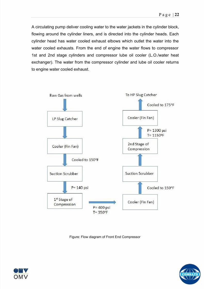
8102019 Gas sweetening Plant
httpslidepdfcomreaderfullgas-sweetening-plant 2662
P a g e | 22
A circulating pump deliver cooling water to the water jackets in the cylinder block
flowing around the cylinder liners and is directed into the cylinder heads Each
cylinder head has water cooled exhaust elbows which outlet the water into the
water cooled exhausts From the end of engine the water flows to compressor
1st and 2nd stage cylinders and compressor lube oil cooler (LOwater heat
exchanger) The water from the compressor cylinder and lube oil cooler returns
to engine water cooled exhaust
Figure Flow diagram of Front End Compressor
8102019 Gas sweetening Plant
httpslidepdfcomreaderfullgas-sweetening-plant 2762
P a g e | 23
Centrifugal Compressor
Centrifugal compressors are machines in which velocity and pressure given to air
or gas in a radial direction by one or more impellers diffuser combination In a
centrifugal compressor the mechanical energy is increased by centrifugal action
The gas enters the suction eye of a high speed rotary element called the impeller
which carries radial vanes integrally cast in it As the impeller rotates the blades
of the impeller force the gas outward from the center the impeller to the outer rim
of impeller the increase in velocity of the gas creates a flow pressure area at the
eye of the impeller The gas at the outer rim of the impeller is forced in to a
passage way called a diffuser where the velocity decreases in the pressure of the
gas
Inlet
The inlet to a centrifugal compressor is typically a simple pipe It may include
features such as a valve and both pressure and temperature instrumentation
Centrifugal impeller
The key component that makes a compressor centrifugal is the centrifugal
impeller shown above It is the impellers rotating set of vanes (or blades) that
gradually raises the energy of the working gas This is identical to an axial
compressor with the exception that the gases can reach higher velocities and
energy levels through the impellers increasing radius
8102019 Gas sweetening Plant
httpslidepdfcomreaderfullgas-sweetening-plant 2862
P a g e | 24
Diffuser
The next key component to the simple centrifugal compressor is the diffuser
Downstream of the impeller in the flow path it is the diffusers responsibility to
convert the kinetic energy (high velocity) of the gas into pressure by gradually
slowing (diffusing) the gas velocity
SEPERATORS
A well-stream is a mixture of gases hydrocarbon liquids water solids and
contaminants Due to variations in pressure and temperature gases evolve from
the liquids water vapor condenses and some of the well-stream changes to liquid
and free gas The separation of well-stream fluids takes place in a separator This
pressure vessel is manufactured in three forms
1 horizontal
2 vertical
3 spherical
To help separation the vessel is normally designed with a series of internal
fittings These fittings are built into the separator to ensure total phase separation
of the well-stream
In gas plants separators are given alternative names due to the function they
perform in the process system A scrubber does a similar job to a knockout drum
However the scrubber usually separates a stream containing high gas-to-liquid
ratios The knockout drum is used where a high degree of liquids are entrained in
the gas
Fluid flow from a well can include gas condensable liquid vapors water water
vapor crude oil and solids As well-stream fluids reach ground level where
pressure is lower than in the reservoir the capacity of the liquid to hold gas in
solution decreases and gas separates out of the oil
Separation depends upon the effect of gravity to separate liquids For adequate
separation one fluid must be lighter than the other fluid For example distillates
8102019 Gas sweetening Plant
httpslidepdfcomreaderfullgas-sweetening-plant 2962
P a g e | 25
(gasoline kerosene etc) and crude oil will not separate in a vessel because they
tend to dissolve in each other Because a separator basically depends upon
gravity to separate the fluids the ease with which separation takes place
depends upon the difference in density of the fluids
Droplets of liquid will separate from gas provided
a) The gas remains in the separator long enough
b) The gas flow remains constant to provoke separation
The difference in density between a gas and liquid will therefore determine the
maximum flow rate of liquid in the vessel
Figure Two phase horizontal separator
Gas bubbles in the liquid will break out in some oil field applications in 30 to 60
seconds Consequently the separator is designed so that the liquid remains in
the vessel for 30 to 60 seconds The length of time that a liquid remains in the
vessel is called its residence time Residence time differs widely from field to field
depending upon viscosity and API Gravity
Another important factor which must be considered is temperature Generally a
decrease in operating temperature will increase the liquid recovery in a separator
8102019 Gas sweetening Plant
httpslidepdfcomreaderfullgas-sweetening-plant 3062
P a g e | 26
as the gas condenses By reducing the pressure on the fluid flash separation
occurs resulting in a flow through the separator which is controlled by external
instrumentation
COALESCENCE
Another important principle in fluid separation is that of coalescence This means
the coming together of liquid droplets created by the force of gravity
A common example of coalescing occurs when drops of water form on the
windshield of a car as it is driven in fog As the tiny drops or water which make up
the fog strike the windshield they combine and eventually form a drop large
enough to run down the glass
Several of the internal devices of a separator such as deflector plates
straightening vanes and even the vessel walls are forms of coalescers In each
vessel drops of liquid adhere to the surface of the device and combine with other
8102019 Gas sweetening Plant
httpslidepdfcomreaderfullgas-sweetening-plant 3162
P a g e | 27
drops until the drop is large enough to fall out The effectiveness of separation
will also depend upon the total amount of coalescing surface area that is present
There are many different types of separators used in the Oil amp Gas industry
Consequently separators are manufactured with one two or several internal
fittings depending on their use and quick removal of these fluids from the vessel
DEFLECTOR PLATES
These are fitted in front of the inlet to the separator and can be net or
dish-shaped Their purpose is to absorb the impact of the incoming fluids and to
encourage the separation of gas and liquids They also slow the flow rate of the
liquids through the vessel
WEIRS
A weir is a metal wall which is fitted across the inside of the vessel normally to a
height of 50 of the overall height of the separator Its purpose is to assist the
process of three phase separation The inlet fluids (oil plus water) are given time
to separate in the liquid accumulation section The water level (interface) is
normally controlled at 50 of the height of the weir Oil floating on the wateroverflows the weir and accumulates in the small oil compartment where it is
drawn off under level control
CENTRIFUGAL DEVICES
These are used in both vertical and horizontal separators for gas-liquid
separation The device imparts a swirling motion to the fluids entering the vessel
Centrifugal force causes the heavier liquids to travel outwards towards the walls
of the vessel and the lighter gases to flow up the centre Centrifugal devices are
also known as cyclones
VORTEX BREAKERS
When liquid flows through a drain outlet a vortex (whirlpool) will form This can
be seen when we pull the plug from a sink or bath tub The same would happen
as water and oil flow from the separator This condition a vortex could allow gas
to flow down the centre of the whirlpool and enter the liquid phase causing
8102019 Gas sweetening Plant
httpslidepdfcomreaderfullgas-sweetening-plant 3262
P a g e | 28
pressurizing of tanks etc To stop this happening vortex breakers are fitted to all
liquid outlets Although they come in a number of different designs vortex
breakers all serve the same purpose - to prevent a whirlpool from forming
MIST OR DEMISTER PADS
The gas which is released from the fluids in the separator still contains droplets of
oil and water which coalesce and fall when the drops get large enough The
demister pad assists in this process Made from knitted wire and contained within
a sturdy frame it causes the gas to continually change its direction of flow
Because gas changes direction far easier than liquid the gas will flow around
each strand of wire whilst the liquid entrained in the gas stream will continue and
stick to the wire
COALESCING PLATES
There are several different forms of coalescing devices the most common of
which are coalescing plates These plates are mounted in the flow stream of the
fluids and assist in breaking down oil-water emulsions The fluid is forced to
follow a path that constantly changes direction This causes the water droplets to
gather together or coalesce and fall to the bottom of the separator The same
principle is used to separate gas and oil mixtures when the oil droplets are
induced to coalesce Simply stated every surface within the separator including
the separator walls assists with the coalescing process
STRAIGHTENlNG VANES
These are often fitted to horizontal separators to remove turbulence in the gas
stream after initial separation at the inlet deflector
FLOAT SHEILD
Internal floats are used as level controllers Any agitation of the liquid surface or
the effect of coalesced liquids falling on the float may cause control problems
Therefore a float shield is fitted to enclose the float creating an area of still liquid
8102019 Gas sweetening Plant
httpslidepdfcomreaderfullgas-sweetening-plant 3362
P a g e | 29
MEMBRANES
The gas contains 12 carbon dioxide and 22 ppm of hydrogen sulphide at 115oF
and 1100 psig This needs to be removed before the gas can be exported The
majority of carbon dioxide hydrogen sulphide and water is removed by means of
membranes
Membranes are thin semipermeable barriers that selectively separate some
compounds from others Currently the only commercially workable membranes
used for CO2 removal are polymer based for example cellulose acetate
polyimides polyamides polysulfone polycarbonates and polyetherimide The
membrane does not operate as a filter where small molecules are separated
from larger ones through a medium with pores rather it separates based on how
well different compounds dissolve into the membrane and diffuse through it The
membranes are manufactured in flat sheets consisting of an extremely thin
nonporous layer mounted on a much-thicker and highly porous layer of the same
material providing mechanical strength The flat sheets are combined into a
spiral-wound element (Figure below) Feed gas enters along the side of the
membrane and passes through the feed spacers As the gas travels between
membrane sheets CO2 H2S and H2O permeate through the membrane and are
collected in the permeate tube The driving force for transport is the high-feed
pressure and low-permeate pressures The gas on the feed side that does not
permeate leaves through the side of the element opposite the feed position Once
the membranes have been manufactured into elements six to 12 elements are
joined together and inserted into a tube Multiple tubes are mounted on skids in a
horizontal orientation
8102019 Gas sweetening Plant
httpslidepdfcomreaderfullgas-sweetening-plant 3462
P a g e | 30
Figure Membrane general Working
In high H2S applications most polymers have been shown to have very little
resistance to H2S plasticization (ldquosofteningrdquo of the membrane) and as a
consequence can only be used at very low H2S partial pressure limits Cellulose
acetate membranes in contrast have been shown to be applicable at extreme
H2S partial pressure conditions It is these membranes that have been utilized in
the testing to determine the limits of membrane performance in high H 2S
applications
The primary membranes used in Kadanwari facility are Cellulose acetate
Cellulose acetic acid and acetic anhydride are mixed together and reacted to
form cellulose acetate polymers This process is aided by the addition of a small
amount of sulfuric acid which is subsequently neutralized during processing
However the membranes are bought from UOP (vendor) and installed for use
8102019 Gas sweetening Plant
httpslidepdfcomreaderfullgas-sweetening-plant 3562
P a g e | 31
How membrane work
The basic principle of separation is selectivity of certain components of a mixture
for the membrane For example the cellulose acetate membrane has very high
selectivity for CO2 and H2S as compared to CH4 Therefore such type of
membrane can be used in gas sweetening process
The selectivity is directly related to the Permeability of gas which accounts that
which gas can pass across the membrane more easily In simple words
membranes being polymer materials are made of long chains of molecules The
different structure of polymer materials only allow selective molecules to pass
through them depending upon chemical and physical compatibility Thus
permeability depends upon choice of polymer
The permeability is determined by permeability coefficient (P) and is product of
solubility (S) and diffusivity (D)
P = S D
Solubility
The solubility is mainly determined by ease of condensation Heavy molecules
are more readily condensed Therefore higher molecular weighted molecules will
more easily condensed and therefore have greater solubility
Molecule Molecular weight
CH4 16
H2S 34
CO2 44
8102019 Gas sweetening Plant
httpslidepdfcomreaderfullgas-sweetening-plant 3662
P a g e | 32
Diffusivity
Diffusivity is ease of molecule to penetrate into some material It depends on size
of gas molecule Here size of molecule is not to be confused by molecular weight
it is the size of the structure Eg the size of O2 molecule is smaller than N2
Molecule Molecular Diameter (Ao)
CO2 33
H2S 36
Ch4 40
For cellulose acetate
DCO2DCH4 S CO2S CH4 P CO2P CH4
45 73 308
Chemical degradation
Cellulose acetate polymer is chemically degraded by a process called hydrolysis
which means breaking apart by the addition of water This is a chemical reaction
in which water is added to the cellulose acetate polymer causing the release of
acetic acid molecules This process proceeds stepwise until all the acetate
groups are released resulting in the reformation of cellulose Moreover alcohols
aromatic hydrocarbons or solvents with chlorine nitro benzene or similar
aromatic solvents will harm the membrane It will expand and lose plastification in
contact with them
Effect of Temperature
The permeation rates of all gases increases with increasing temperature
however membrane selectivity for CO2 over hydrocarbon decreases at higher
8102019 Gas sweetening Plant
httpslidepdfcomreaderfullgas-sweetening-plant 3762
P a g e | 33
temperature Consequently CO2 removal will improve as operating temperature
increases but hydro carbon recovery will decrease
Primary Membrane
The primary membranes comprise of two trains Each train consists of two
sections AB and CD each section consists of a 30 tube membrane skid (A and
C) followed by a 25 tube skid (B and D) The conditioned gas (after pre-
treatment) enters the primary membrane via the particulate filter adjacent to the
skid The gas is fed to the membranes through a common inlet manifold which
supplies primary membranes skids A and C A pressure control loop located
upstream of the manual inlet isolation valve is provided to maintain a constant
supply pressure to the membrane skid and to allow for preheating at the inlet
prior to skid start-up This pressure control loop can also be used during start-up
to control the pressurization of the pretreatment skid and associated pipes to the
primary membranes
The gas passes through membrane skid A the residual gas exiting the membrane
skid is sent to skid B and the permeate to common permeate discharge header An
identical arrangement is provide on the inlet to skid C as provided on skid A Theresidual gas from skid B combines with the residual gas from skid D in a common
discharge header and is then sent to the H2S polishing towers via the feed coolers
on the pre-treatment skid The permeate from skid B is sent to the common
permeate discharge header The permeate discharge header sends the gas to
either the recycle compressor or the vent header via a pressure control loop
Overpressure protection for the membranes is provided by a pressure safety valve
on the supply header to the membrane banks
8102019 Gas sweetening Plant
httpslidepdfcomreaderfullgas-sweetening-plant 3862
P a g e | 34
Secondary (Recycle) Membrane
The recycle membranes comprise of a single train with two skids each with four
banks of membrane tubes The conditioned gas from the discharge of the recycle
pre-treatment skid is routed to the first recycle membrane skid The gas passes
through the membranes the residual gas is fed to primary membrane (skid A) inlet
via feed gas cooler and permeate to the common permeate discharge header An
identical arrangement is provide on the inlet to skid B Permeate from the recycle
membrane skids A and B is routed to the vent header Some portion of permeate is
heated and sent for regeneration in Mem-Guard units Nitrogen purge can be
connected downstream of the inlet isolation valve on each skid to enable the
membrane tubes to be purged and left pressurized during prolonged shutdown
8102019 Gas sweetening Plant
httpslidepdfcomreaderfullgas-sweetening-plant 3962
P a g e | 35
Figure Flow Diagram of Recycle membrane unit
8102019 Gas sweetening Plant
httpslidepdfcomreaderfullgas-sweetening-plant 4062
P a g e | 36
ADVANTAGES OF MEMBRANE SYSTEMS
Membrane systems have major advantages over more-traditional methods of
acid gas removal
Lower capital cost Membrane systems are skid mounted and so the
scope cost and time taken for site preparation are minimal Installation
costs are significantly lower than alternative technologies especially for
remote areas Furthermore no additional facilities for solvent storage and
water treatment needed by other processes are required
Lower operating costs The only major operating cost for single-stage
membrane systems is membrane replacement This cost is significantly
lower than the solvent replacement and energy costs associated with
traditional technologies The improvements in membrane and
pretreatment design allow a longer useful membrane life which further
reduces operating costs The energy costs of multistage systems with
large recycle compressors are usually comparable to those for traditionaltechnologies
Deferred capital investment Often contracted sales-gas flow rates
increase over time as more wells are brought on-line With traditional
technologies the system design needs to take this later production into
account immediately and so the majority of the equipment is installed
before it is even needed The modular nature of membrane systems
means that only the membranes that are needed at start-up need be
installed The rest can be added either into existing tubes or in new skids
only when they are required
Operational simplicity and high reliability Because single-stage
membrane systems have no moving parts they have almost no
8102019 Gas sweetening Plant
httpslidepdfcomreaderfullgas-sweetening-plant 4162
P a g e | 37
unscheduled downtime and are extremely simple to operate They can
operate unattended for long periods of time The addition of a recycle
compressor adds some complexity to the system but still much less than
with a solvent- or adsorbent-based technology Multistage systems can be
operated at full capacity as single-stage systems when the recycle
compressor is down
Good weight and space efficiency Skid construction can be optimized
to the space available This space efficiency is especially important for
offshore environments where deck area is at a premium and is the
reason why so many new offshore developments have chosen to use
membranes for acid gas removal Figure 6 illustrates the space efficiency
of membrane systems The membrane unit in the lower left corner
replaced all the amine and glycol plant equipment shown in the rest of the
picture
Adaptability Because membrane area is dictated by the percentage of
acid gas removal rather than absolute acid gas removal small variations
in feed acid gas content hardly change the sales-gas acid gas
specification For example a system designed for 10 down to 3 acid
gas removal produces a 35 product from a 12 feed gas and a 5
product from a 15 feed gas
Design efficiency The membrane and pretreatment systems integrate a
number of operations such as dehydration CO2 and H2S removal dew-
point control and mercury removal Traditional acid gas removal
technologies require all of these operations as separate processes and
may also require additional dehydration because some technologies
saturate the product stream with water
8102019 Gas sweetening Plant
httpslidepdfcomreaderfullgas-sweetening-plant 4262
P a g e | 38
Power generation The permeate gas from membrane systems can be
used to provide fuel gas for power generation either for a recycle
compressor or other equipment
Ideal for debottlenecking Because expanding solvent- or adsorbent-
based acid gas removal plants without adding additional trains is difficult
an ideal solution is to use membranes for bulk acid gas removal and leave
the existing plant for final cleanup An additional advantage is that the
permeate gas from the membrane system can often be used as fuel for
the existing plant thus avoiding significant increase in hydrocarbon
losses
Environmentally friendly Membrane systems do not involve the
periodic removal and handling of spent solvents or adsorbents Permeate
gases can be flared used as fuel or re-injected into the well Items thatdo need disposal such as spent membrane elements can be incinerated
Ideal for remote locations Many of the factors mentioned above make
membrane systems a highly desirable technology for remote locations
where spare parts are rare and labor unskilled Furthermore solvents
storage and trucking water supply power generation or extensive
infrastructure are not required
Re-injection optimizations Since the permeate stream from the
membrane system can be operated at elevated pressures it is possible to
further pressurize by re-injection compression train
8102019 Gas sweetening Plant
httpslidepdfcomreaderfullgas-sweetening-plant 4362
P a g e | 39
Sorption
Sorption is a physical and chemical process by which one substance becomes
attached to another
It is of two main types
1 Absorption
2 Adsorption
Absorption
Absorption is a physical or chemical phenomenon or process in which atoms
molecules or ions enter some bulk phase ndash gas liquid or solid material This is a
different process from adsorption since molecules undergoing absorption are
taken up by the volume not by the surface (as in the case for adsorption)
Absorption process may be chemical (reactive) or physical (non-reactive)
Physical absorption
Physical absorption or non-reactive absorption is made between two phases ofmatter a liquid absorbs a gas or a solid absorbs a liquid
When a liquid solvent absorbs a gas mixture or part of it a mass of gas moves
into the liquid For example water may absorb oxygen from the air This mass
transfer takes place at the interface between the liquid and the gas at a rate
depending on both the gas and the liquid This type of absorption depends on the
solubility of gases the pressure and the temperature The rate and amount of
absorption also depend on the surface area of the interface and its duration in
time
When a solid absorbs a liquid mixture or part of it a mass of liquid moves into the
solid For example a clay pot used to store water may absorb some of the water
This mass transfer takes place at the interface between the solid and the liquid
at a rate depending on both the solid and the liquid
8102019 Gas sweetening Plant
httpslidepdfcomreaderfullgas-sweetening-plant 4462
P a g e | 40
Chemical absorption
Chemical absorption or reactive absorption is a chemical reaction between the
absorbed and the absorbing substances Sometimes it combines with physical
absorption This type of absorption depends upon the stoichiometry of the
reaction and the concentration of its reactants
Adsorption
Adsorption is the adhesion of atoms ions or molecules from a gas liquid or
dissolved solid to a surface This process creates a film of the adsorbate on the
surface of the adsorbent The binding to the surface is usually weak and
reversible Compounds with color and those that have taste or odor tend to bind
strongly Compounds that vibrate at frequencies in the visible spectrum are very
often are strongly adsorbed on activated carbon
The most common industrial adsorbents are activated carbon silica gel and
alumina because they present enormous surface areas per unit weight
Depending on the nature of attractive forces existing between the adsorbate and
adsorbent adsorption can be classified as
i) Physical adsorption
ii) Chemical adsorption
i) Physical adsorption (Physisorption)
In physical adsorption the forces of attraction between the molecules of the
adsorbate and the adsorbent are of the weak van der Waals type Since the
forces of attraction are weak the process of physisorption can be easily reversed
by heating or decreasing the pressure of the adsorbate (as in the case of gases)
8102019 Gas sweetening Plant
httpslidepdfcomreaderfullgas-sweetening-plant 4562
P a g e | 41
ii) Chemical adsorption (Chemisorption)
In chemisorption the forces of attraction between the adsorbate and the
adsorbent are very strong the molecules of adsorbate form chemical bonds with
the molecules of the adsorbent present in the surface
Adsorption is generally accompanied by release of energy that is most
adsorption processes are exothermic in nature Adsorption is a spontaneous
process therefore its free energy change is negative (∆Glt0) However the
entropy change associated with adsorption is generally negative because the
adsorbate molecules lose their translation freedom when they get attached to the
surface of the adsorbent Therefore in order for ∆G to be negative the enthalpy
change (∆H) must be sufficiently negative such that (∆G=∆H-T∆S) lt 0 This
explanation accounts for exothermic adsorption processes In cases where
endothermic adsorption occurs the entropy change ∆S is sufficiently positive
such that ∆G remains negative
Pre treatment
The main function of pretreatment skid is to provide membrane inlet specification
gas as mentioned by the vendor UOP It removes the contaminants that would
poison the membranes like dust solids (adsorbent particles) lube oil heavy
hydrocarbons etc It consists of
Feed Cooler
Feed Gas Scrubber
Filter Coalescer
Feed Gas Heater
Activated Carbon Guard Filter
Particle Filter
8102019 Gas sweetening Plant
httpslidepdfcomreaderfullgas-sweetening-plant 4662
8102019 Gas sweetening Plant
httpslidepdfcomreaderfullgas-sweetening-plant 4762
P a g e | 43
The regeneration is carried out by heated permeate gas from the recycle
membranes at 450oF The vessel is depressurized to 20 psi and heated gas is
introduced from top The gas carries out the adsorbed contaminants and leaves
the vessel from bottom cleaning the adsorbent This contaminated gas is burnt in
the flare
UOP the vendor of Memguard unit has never disclosed that what substance
MG3 and MG5 exactly are But as mentioned by vendor that both care class of
aluminosilicates Therefore MG3 can be potassium aluminosilicate and MG5 can
be Calcium aluminosilicate These are molecular sieves adsorbents Molecular
sieves are a microporous material which can selectively adsorb gases andliquids They are synthetic zeolites (crystalline metal aluminosilicates) which
upon dehydration can efficiently and selectively remove water or other
solvents The selectivity of a molecular sieve is determined by its pore size
molecules with a critical diameter which is less than the pore size will be
efficiently adsorbed while larger molecules will be excluded
8102019 Gas sweetening Plant
httpslidepdfcomreaderfullgas-sweetening-plant 4862
P a g e | 44
3A Molecular Sieve Adsorbent
The 3A molecular sieve adsorbent has a 3 angstrom (3A) pore size which means
that any molecule that is larger than the 3 angstrom pores will not be adsorbed
The 3A molecular sieve is the potassium type of A crystalline structure and is a
form of alkali Aluminosilicate For a 3A molecular sieve the sequence rate that
adsorption occurs is He Ne N and H2O
Due to the crystalline structure molecular sieves that have a 3 angstrom pore
size have a very high rate of adsorption and properties that promote a longer life
for products treated by the sieve The most common use for the 3A molecular
sieve is to remove water and moisture from materials that are in gas and liquid
form
5A Molecular Sieve Adsorbent
These are molecular sieve adsorbents with a pore size of 5 angstrom (5A) 5A
molecular sieves are unable to adsorb any molecules or impurities that are
smaller than 5A It is calcium form of type A crystalline structure and is form of analkali-aluminosilicate that is most commonly used to separate isomerous alkanes
from normal alkanes and to co-adsorb moisture and water along with carbon
dioxide from gases In additional 5A molecular sieves are used for gaseous
pressure swing adsorption (PSA)mdashthat is to separate particular gases from other
gases
Adsorption of nC4H10
Adsorption of nC4H10
Adsorption of C3H8 to C22H46
Adsorption of Freon-12 (dichlorodifluoromethane)
Natural gas drying
Normal- and iso-paraffin separation
Separation of aromatic
8102019 Gas sweetening Plant
httpslidepdfcomreaderfullgas-sweetening-plant 4962
P a g e | 45
Inlet Composition of Memguard vessel
COMPSOSITION MOLE
CARBON DIOXIDE 1096
MEHTANE 8593
ETHANE 173
PROPANE 023
I-BUTANE 008
N BUTANE 004
PENTANES 004
HEXANE + 000
NITROGEN 076
WATER 007
Outlet Composition of Memguard vessel
COMPSOSITION MOLE
CARBON DIOXIDE 1098
MEHTANE 8608
ETHANE 173
PROPANE 023
I-BUTANE 008N BUTANE 004
PENTANES 004
HEXANE + 000
NITROGENT 076
WATER 000
H2S polisher
The H2S polishing unit has been designed to treat 187 MMscfday of natural gas
containing up to 11 CO2 and 21 ppm H2S where the level of the CO2 and H2S
is reduced using a MemGuard Membrane separation unit The unit is situated
down-stream of the membrane unit and will further reduce the level of H2S in the
processed gas to a sales gas specification of 38 ppm
8102019 Gas sweetening Plant
httpslidepdfcomreaderfullgas-sweetening-plant 5062
P a g e | 46
This process uses three non-regenerable fixed bed absorber vessels using a low
temperature high activity absorbent The absorbent is a mixture of activated
metal oxides (mainly zinc oxide) The three towers can are generally operated in
parallel arrangement but on demand can be used in series (any of alternate
arrangements of A B C vessels) as shown in figure
The higher sales gas flow rate increased the catalyst consumption and
replacement frequency
ZnO + H2S =gt ZnS + H20
Routine samples are taken from the beds to provide a check on each bed
performance and to follow the saturation profile during the absorbent life After
the adsorbent has been fully utilized the adsorption vessels are recharged with
new adsorbent discarding the utilized one in a safe manner
109oF
1215 psig
Before H2S Polishing After H2S Polishing
8102019 Gas sweetening Plant
httpslidepdfcomreaderfullgas-sweetening-plant 5162
P a g e | 47
Figure
H2S Tower
Inlet pipe
4 Drums of 19mm
ceramic Balls
6 Micron mesh
5 Drums of 50mmceramic
1 Drums of19mm ceramic
01 Drums of6mm ceramic
112 drums of
Catalist ZnO
8102019 Gas sweetening Plant
httpslidepdfcomreaderfullgas-sweetening-plant 5262
P a g e | 48
Recycle Compressor
The permeate gas of the primary membrane unit carries recoverable amount of
CH4 It is fed to recycle membrane unit for further CH 4 recovery But the
permeate pressure from primary membranes which has been reduced to 12 psi
must be regenerated to 1200 psi for the gas to be fed again to the system For
this purpose we have employed recycle compressor The compressor is a four
stage centrifugal compressor It is driven by gas turbine of 31200 HP It has 25
MW producing capacity
Figure Recycle Compressor Process Flow Diagram
8102019 Gas sweetening Plant
httpslidepdfcomreaderfullgas-sweetening-plant 5362
P a g e | 49
Sales Gas Compressor
Gas from H2S polishing unit is sent to sales gas compressor where its pressure
is enhanced to 1100 psi so it may be injected to SNGPL high pressure trunk line
Sales gas compressor is single stage gas turbine driven
Figure Process Flow of Sales Gas Compressor
8102019 Gas sweetening Plant
httpslidepdfcomreaderfullgas-sweetening-plant 5462
P a g e | 50
Cooling Towers
A cooling tower is a heat rejection device which extracts waste heat to theatmosphere through the cooling of a water stream to a lower temperature Hot
water from the system enters the cooling tower and is distributed over the fill
(heat transfer surface) Air is induced or forced through the fill causing a small
portion of the water to evaporate This evaporation removes heat from the
remaining water which is collected in the cold water basin and returned to the
system to absorb more heat Each cooling tower line although operating under
the same basic principle of operation is arranged a little differently
Types
Natural draft mdash Utilizes buoyancy via a tall chimney Warm moist air naturally
rises due to the density differential compared to the dry cooler outside air Warm
moist air is less dense than drier air at the same pressure This moist air
buoyancy produces an upwards current of air through the tower
Mechanical draft mdash Uses power-driven fan motors to force or draw airthrough the tower
o Induced draft mdash A mechanical draft tower with a fan at the
discharge (at the top) which pulls air up through the tower The fan
induces hot moist air out the discharge This produces low entering
and high exiting air velocities reducing the possibility of
recirculation in which discharged air flows back into the air intake
o Forced draft mdash A mechanical draft tower with a blower type fan at
the intake The fan forces air into the tower creating high entering
and low exiting air velocities The low exiting velocity is much more
susceptible to recirculation This fanfill geometry is also known as
blow-through
8102019 Gas sweetening Plant
httpslidepdfcomreaderfullgas-sweetening-plant 5562
P a g e | 51
Forced Draft Cooling Tower Vs Induced Draft Cooling Tower
Induced Draft Cooling Tower have the ability to handle large water flow
rate than Forced Draft Cooling Tower
Induced Draft Cooling Tower is suitable for large cell sizes and fan sizes
as compared with Forced Draft Larger fan size may result in greater
efficiency and consequently lower power and sound level
Forced Draft Cooling Tower can be square or rectangular type only
however Induced Draft Cooling Towers can be round square or
rectangular type
Induced Draft Cooling Tower uses more compact ground area than Forced
Draft Cooling Tower equivalent capacity due to absence of fan on one
side
Fan equipment is warm exhaust air is less liable to icing up in winter
operation (Cold Countries)
Higher velocity in Forced Draft Cooling Tower cause drop in suspension
and cause additional static resistance to system
Configuration
There are two main configurations of factory assembled cooling towers crossflow
and counterflow In crossflow cooling towers the water flows vertically down the
fill as air flows horizontally across In counterflow cooling towers the water flows
vertically down the fill as air flows vertically up
Crossflow Configuration Counterflow Configuration
8102019 Gas sweetening Plant
httpslidepdfcomreaderfullgas-sweetening-plant 5662
P a g e | 52
Drift mdash Water droplets that are carried out of the cooling tower with the exhaust
air Drift droplets have the same concentration of impurities as the water entering
the tower The drift rate is typically reduced by employing baffle-like devices
called drift eliminators through which the air must travel after leaving the fill and
spray zones of the tower
Blow-out mdash Water droplets blown out of the cooling tower by wind generally at
the air inlet openings Water may also be lost in the absence of wind through
splashing or misting Devices such as wind screens louvers splash deflectors
and water diverters are used to limit these losses
Blow-down mdash The portion of the circulating water flow that is removed (usually
discharged to a drain) in order to maintain the amount of Total Dissolved Solids
(TDS) and other impurities at an acceptably low level Higher TDS concentration
in solution may result from greater cooling tower efficiency However the higher
the TDS concentration the greater the risk of scale biological growth and
corrosion
Make-up mdash The water that must be added to the circulating water system in
order to compensate for water losses such as evaporation drift loss blow-out
blow-down etc
Approach mdash The approach is the difference in temperature between the cooled-
water temperature and the entering-air wet bulb temperature
Range mdash The range is the temperature difference between the warm water inlet
and cooled water exit
Fill mdash Inside the tower fills are added to increase contact surface as well as
contact time between air and water to provide better heat transfer The efficiency
of the tower depends on the selection and amount of fill
8102019 Gas sweetening Plant
httpslidepdfcomreaderfullgas-sweetening-plant 5762
P a g e | 53
There are two types of fills that may be used
o Film type fill (causes water to spread into a thin film)
o Splash type fill (breaks up falling stream of water and interrupts its
vertical progress)
Important
Scale build up is controlled by adding chemicals to the cooling loop and diluting
the concentration by blow down and make-up Following chemicals are added to
the Cooling to control CorrosionSale and microbial growth
Corrosion Inhibitor To control corrosion in the Cooling system
Dispersant To kept ions in suspension to avoid settle down and buildup
Sodium hypo Chlorite To Control microbial Growth
Acid To control Alkalinity in the system
High Stress Polymer To run the system at higher conductivity It is a
multifunctional polymer for Zinc amp Phosphate stabilization in cooling tower
Fin Fan Cooler
Fin fan heat exchanger is simply a pressure vessel which cools a circulating fluid
within finned tubes by forcing ambient air over the exterior of the tubes A
common example of an air cooler is a carrsquos radiator Fin Fan Coolers are used in
any application where large quantities of heat need to be transferred This
includes chemical and petrochemical industries power stations waste-to-energy
facilities as well as steelworks
Fin Fan Cooler are used for two primary reasons
They increase plant efficiency
They are a green solution as compared to cooling towers and shell and
tube heat exchangers because they do not require an auxiliary water
8102019 Gas sweetening Plant
httpslidepdfcomreaderfullgas-sweetening-plant 5862
P a g e | 54
supply (water lost due to drift and evaporation plus no water treatment
chemicals are required)
Figure General Overview of Fin Fan Cooler
Produced Water
The produced water system receives liquid from the equipment Miano slug
catcher train 1 and 2 inlet separators and is fed to three phase separator where
water oil and gas is separated The gases produced are burnt in incinerator
whereas hydrocarbon liquid is stored to be sold Liquid from compressors
recycle inlet separator recycle feed scrubber high and low pressure slug
catchers is passed to degasser Separated water is injected down the earth
Incinerator
The term incinerate means to burn something until nothing is left but ashes An
incinerator is a unit or facility used to burn trash and other types of waste until it is
reduced to ash An incinerator is constructed of heavy well-insulated materials
so that it does not give off extreme amounts of external heat The high levels of
heat are kept inside the furnace or unit so that the waste is burned quickly and
efficiently If the heat were allowed to escape the waste would not burn as
completely or as rapidly
8102019 Gas sweetening Plant
httpslidepdfcomreaderfullgas-sweetening-plant 5962
P a g e | 55
Control System
The plant is controlled at CCR (Central Control Room) by PLCs (Programmable
Logic Controllers) through fiber optic control line All control parameters are
received at LER (Local Equipment Room) via two optic fiber control lines One
being primary and other secondary operating in redundancy ie if primary fails
control shifts to secondary These control parameters are sent to CCR via single
optic fiber cable
Safety System
Wellheads and Gas Processing Plant have their own Fire amp Gas detection
systems emergency shutdown (ESD) Plant has a fault tolerant controller It is
based on Triple Modular Redundant (TMR) architecture manufactured by
Triconex The TMR system is based on three isolated parallel control systems
integrated into one system The system operates on a two out of three voting
principle which provides high integrity error free uninterrupted operation with no
single point of failure The TMR receives inputs from Process Sensors Manual
Switches Fire amp Gas Detectors Packaged Equipment Control Systems and
Product Exporting Facilities The TMR carries out cause and effect processing on
the data received and where necessary produces output signals Outputs from
the TMR are hard wired directly to ESD shutdown and blow down valve
solenoids motor control instrumentelectrical interfaces to control electrical
drives package equipment logic control systems manifold area as well as
telecoms
The operator in central control room is able to accept alarms and once the fault
has been cleared reset the input All the control systems are centralized to a
single interface All the PLCs (Programmable Logic Controllers) communicate with
the servers and servers communicate with the clients through Ethernet connectivity
Centralization eases the navigation of different systems at a common interface
Emergency Shutdown
The ESD system receives inputs from field mounted instrumentation on the process
8102019 Gas sweetening Plant
httpslidepdfcomreaderfullgas-sweetening-plant 6062
P a g e | 56
and utility equipment and initiates executive actions appropriate to the level of ESD
The system is an Active system which is in standby and will activate when in an
alarm or fault condition The Kadanwari Gas Process Facility ESD system is
comprised of five (5) levels The emergency severity decreases with increasing ESD
level number
ESD 1
This shutdown level is automatically initiated by fire major gas leak or a detected
toxic atmosphere in the process area of the plant or manually from CCR A level 1
shutdown will cause all production to cease close all emergency shutdown
valves stop the process and shutdown of the main power generation The
emergency vent valves to the stack will open and in addition all equipment of zone 1
certified will be isolated This is the highest level of ESD and will cause the following
to occur
All Shutdown Valves (SDVs) on the process facility will close All slowdown Valves (BDVs) on the process facility will open
All Main Gas Driven Generators will be tripped
Emergency Diesel Generator will start
All electrical power to process and utility rotating equipment will be
isolated
Wellhead Choke Valves Close Wing Valves Close Upper Master Valve
(UMV) Close
ESD 2
This shutdown level is activated automatically if a major process or utility failure
occurs or manually from CCR All production to the plant from the wellhead is
stopped All emergency shutdown valves trip to their fail safe position
Venting shall be as specified This level of ESD will cause the following to occur
8102019 Gas sweetening Plant
httpslidepdfcomreaderfullgas-sweetening-plant 6162
P a g e | 57
All Shutdown Valves (SDVs) on the process facility will close
All electrical power to process and utility rotating equipment will be
isolated
Wellhead Choke Valve Close Wing Valves Close and Upper Master Valve(UMV) Close
ESD 3
The level 3 shutdown isolates and stops a single process train only Production
continues via the other train This ESD level is initiated by process conditions or
operator at local panel This level of ESD will cause the following to occur
ESD 3A Train 1 production to cease
ESD 3B Train 2 production to cease
All online wellhead choke valves go to minimum flow ie (1O )
ESD 4
A level 4 shutdown shall cease all production from an entire field either
Kadanwari or Miano upstream of the associated slug catchers ESD 4K for
Kadanwari amp ESD 4M for Miano This ESD level is initiated automatically by slug
catcher abnormal process conditions This level of ESD will cause the following
to occur
All SDVs close isolating the relevant slug catcher and its upstream gas
production facility from the Kadanwari Gas Processing Plant
All Wellhead Choke Valves Close Wing Valves Close and Upper MasterValves (UMV) of the relevant gas production facility Close
A parallel timer is provided to close within 10 second if not closed in given
time SSSV seals the well
ESD 5
A level 5 shutdown represents equipment shutdown for the protection of the
individual equipment without any change in the process This level of ESD is for the
protection of various pieces of equipment and is initiated by its own inputs eg
8102019 Gas sweetening Plant
httpslidepdfcomreaderfullgas-sweetening-plant 6262
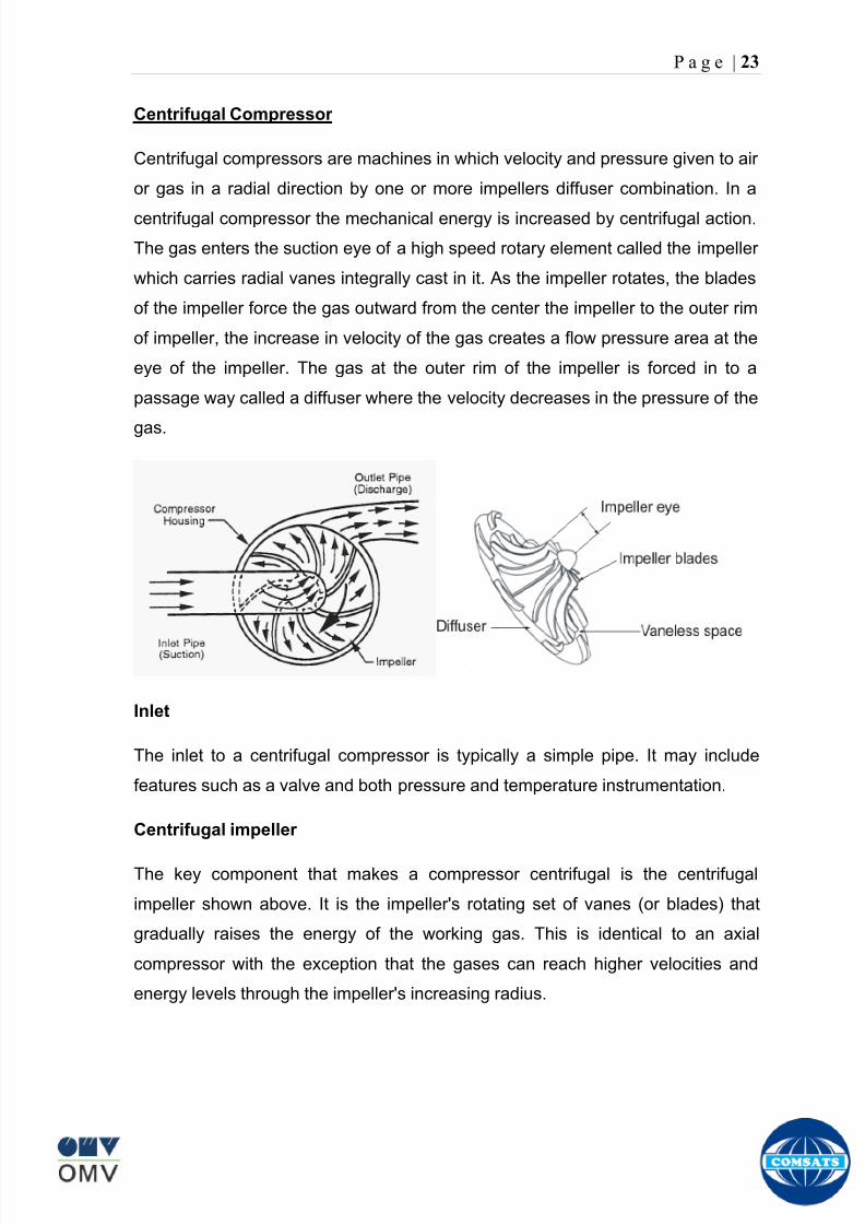
8102019 Gas sweetening Plant
httpslidepdfcomreaderfullgas-sweetening-plant 2762
P a g e | 23
Centrifugal Compressor
Centrifugal compressors are machines in which velocity and pressure given to air
or gas in a radial direction by one or more impellers diffuser combination In a
centrifugal compressor the mechanical energy is increased by centrifugal action
The gas enters the suction eye of a high speed rotary element called the impeller
which carries radial vanes integrally cast in it As the impeller rotates the blades
of the impeller force the gas outward from the center the impeller to the outer rim
of impeller the increase in velocity of the gas creates a flow pressure area at the
eye of the impeller The gas at the outer rim of the impeller is forced in to a
passage way called a diffuser where the velocity decreases in the pressure of the
gas
Inlet
The inlet to a centrifugal compressor is typically a simple pipe It may include
features such as a valve and both pressure and temperature instrumentation
Centrifugal impeller
The key component that makes a compressor centrifugal is the centrifugal
impeller shown above It is the impellers rotating set of vanes (or blades) that
gradually raises the energy of the working gas This is identical to an axial
compressor with the exception that the gases can reach higher velocities and
energy levels through the impellers increasing radius
8102019 Gas sweetening Plant
httpslidepdfcomreaderfullgas-sweetening-plant 2862
P a g e | 24
Diffuser
The next key component to the simple centrifugal compressor is the diffuser
Downstream of the impeller in the flow path it is the diffusers responsibility to
convert the kinetic energy (high velocity) of the gas into pressure by gradually
slowing (diffusing) the gas velocity
SEPERATORS
A well-stream is a mixture of gases hydrocarbon liquids water solids and
contaminants Due to variations in pressure and temperature gases evolve from
the liquids water vapor condenses and some of the well-stream changes to liquid
and free gas The separation of well-stream fluids takes place in a separator This
pressure vessel is manufactured in three forms
1 horizontal
2 vertical
3 spherical
To help separation the vessel is normally designed with a series of internal
fittings These fittings are built into the separator to ensure total phase separation
of the well-stream
In gas plants separators are given alternative names due to the function they
perform in the process system A scrubber does a similar job to a knockout drum
However the scrubber usually separates a stream containing high gas-to-liquid
ratios The knockout drum is used where a high degree of liquids are entrained in
the gas
Fluid flow from a well can include gas condensable liquid vapors water water
vapor crude oil and solids As well-stream fluids reach ground level where
pressure is lower than in the reservoir the capacity of the liquid to hold gas in
solution decreases and gas separates out of the oil
Separation depends upon the effect of gravity to separate liquids For adequate
separation one fluid must be lighter than the other fluid For example distillates
8102019 Gas sweetening Plant
httpslidepdfcomreaderfullgas-sweetening-plant 2962
P a g e | 25
(gasoline kerosene etc) and crude oil will not separate in a vessel because they
tend to dissolve in each other Because a separator basically depends upon
gravity to separate the fluids the ease with which separation takes place
depends upon the difference in density of the fluids
Droplets of liquid will separate from gas provided
a) The gas remains in the separator long enough
b) The gas flow remains constant to provoke separation
The difference in density between a gas and liquid will therefore determine the
maximum flow rate of liquid in the vessel
Figure Two phase horizontal separator
Gas bubbles in the liquid will break out in some oil field applications in 30 to 60
seconds Consequently the separator is designed so that the liquid remains in
the vessel for 30 to 60 seconds The length of time that a liquid remains in the
vessel is called its residence time Residence time differs widely from field to field
depending upon viscosity and API Gravity
Another important factor which must be considered is temperature Generally a
decrease in operating temperature will increase the liquid recovery in a separator
8102019 Gas sweetening Plant
httpslidepdfcomreaderfullgas-sweetening-plant 3062
P a g e | 26
as the gas condenses By reducing the pressure on the fluid flash separation
occurs resulting in a flow through the separator which is controlled by external
instrumentation
COALESCENCE
Another important principle in fluid separation is that of coalescence This means
the coming together of liquid droplets created by the force of gravity
A common example of coalescing occurs when drops of water form on the
windshield of a car as it is driven in fog As the tiny drops or water which make up
the fog strike the windshield they combine and eventually form a drop large
enough to run down the glass
Several of the internal devices of a separator such as deflector plates
straightening vanes and even the vessel walls are forms of coalescers In each
vessel drops of liquid adhere to the surface of the device and combine with other
8102019 Gas sweetening Plant
httpslidepdfcomreaderfullgas-sweetening-plant 3162
P a g e | 27
drops until the drop is large enough to fall out The effectiveness of separation
will also depend upon the total amount of coalescing surface area that is present
There are many different types of separators used in the Oil amp Gas industry
Consequently separators are manufactured with one two or several internal
fittings depending on their use and quick removal of these fluids from the vessel
DEFLECTOR PLATES
These are fitted in front of the inlet to the separator and can be net or
dish-shaped Their purpose is to absorb the impact of the incoming fluids and to
encourage the separation of gas and liquids They also slow the flow rate of the
liquids through the vessel
WEIRS
A weir is a metal wall which is fitted across the inside of the vessel normally to a
height of 50 of the overall height of the separator Its purpose is to assist the
process of three phase separation The inlet fluids (oil plus water) are given time
to separate in the liquid accumulation section The water level (interface) is
normally controlled at 50 of the height of the weir Oil floating on the wateroverflows the weir and accumulates in the small oil compartment where it is
drawn off under level control
CENTRIFUGAL DEVICES
These are used in both vertical and horizontal separators for gas-liquid
separation The device imparts a swirling motion to the fluids entering the vessel
Centrifugal force causes the heavier liquids to travel outwards towards the walls
of the vessel and the lighter gases to flow up the centre Centrifugal devices are
also known as cyclones
VORTEX BREAKERS
When liquid flows through a drain outlet a vortex (whirlpool) will form This can
be seen when we pull the plug from a sink or bath tub The same would happen
as water and oil flow from the separator This condition a vortex could allow gas
to flow down the centre of the whirlpool and enter the liquid phase causing
8102019 Gas sweetening Plant
httpslidepdfcomreaderfullgas-sweetening-plant 3262
P a g e | 28
pressurizing of tanks etc To stop this happening vortex breakers are fitted to all
liquid outlets Although they come in a number of different designs vortex
breakers all serve the same purpose - to prevent a whirlpool from forming
MIST OR DEMISTER PADS
The gas which is released from the fluids in the separator still contains droplets of
oil and water which coalesce and fall when the drops get large enough The
demister pad assists in this process Made from knitted wire and contained within
a sturdy frame it causes the gas to continually change its direction of flow
Because gas changes direction far easier than liquid the gas will flow around
each strand of wire whilst the liquid entrained in the gas stream will continue and
stick to the wire
COALESCING PLATES
There are several different forms of coalescing devices the most common of
which are coalescing plates These plates are mounted in the flow stream of the
fluids and assist in breaking down oil-water emulsions The fluid is forced to
follow a path that constantly changes direction This causes the water droplets to
gather together or coalesce and fall to the bottom of the separator The same
principle is used to separate gas and oil mixtures when the oil droplets are
induced to coalesce Simply stated every surface within the separator including
the separator walls assists with the coalescing process
STRAIGHTENlNG VANES
These are often fitted to horizontal separators to remove turbulence in the gas
stream after initial separation at the inlet deflector
FLOAT SHEILD
Internal floats are used as level controllers Any agitation of the liquid surface or
the effect of coalesced liquids falling on the float may cause control problems
Therefore a float shield is fitted to enclose the float creating an area of still liquid
8102019 Gas sweetening Plant
httpslidepdfcomreaderfullgas-sweetening-plant 3362
P a g e | 29
MEMBRANES
The gas contains 12 carbon dioxide and 22 ppm of hydrogen sulphide at 115oF
and 1100 psig This needs to be removed before the gas can be exported The
majority of carbon dioxide hydrogen sulphide and water is removed by means of
membranes
Membranes are thin semipermeable barriers that selectively separate some
compounds from others Currently the only commercially workable membranes
used for CO2 removal are polymer based for example cellulose acetate
polyimides polyamides polysulfone polycarbonates and polyetherimide The
membrane does not operate as a filter where small molecules are separated
from larger ones through a medium with pores rather it separates based on how
well different compounds dissolve into the membrane and diffuse through it The
membranes are manufactured in flat sheets consisting of an extremely thin
nonporous layer mounted on a much-thicker and highly porous layer of the same
material providing mechanical strength The flat sheets are combined into a
spiral-wound element (Figure below) Feed gas enters along the side of the
membrane and passes through the feed spacers As the gas travels between
membrane sheets CO2 H2S and H2O permeate through the membrane and are
collected in the permeate tube The driving force for transport is the high-feed
pressure and low-permeate pressures The gas on the feed side that does not
permeate leaves through the side of the element opposite the feed position Once
the membranes have been manufactured into elements six to 12 elements are
joined together and inserted into a tube Multiple tubes are mounted on skids in a
horizontal orientation
8102019 Gas sweetening Plant
httpslidepdfcomreaderfullgas-sweetening-plant 3462
P a g e | 30
Figure Membrane general Working
In high H2S applications most polymers have been shown to have very little
resistance to H2S plasticization (ldquosofteningrdquo of the membrane) and as a
consequence can only be used at very low H2S partial pressure limits Cellulose
acetate membranes in contrast have been shown to be applicable at extreme
H2S partial pressure conditions It is these membranes that have been utilized in
the testing to determine the limits of membrane performance in high H 2S
applications
The primary membranes used in Kadanwari facility are Cellulose acetate
Cellulose acetic acid and acetic anhydride are mixed together and reacted to
form cellulose acetate polymers This process is aided by the addition of a small
amount of sulfuric acid which is subsequently neutralized during processing
However the membranes are bought from UOP (vendor) and installed for use
8102019 Gas sweetening Plant
httpslidepdfcomreaderfullgas-sweetening-plant 3562
P a g e | 31
How membrane work
The basic principle of separation is selectivity of certain components of a mixture
for the membrane For example the cellulose acetate membrane has very high
selectivity for CO2 and H2S as compared to CH4 Therefore such type of
membrane can be used in gas sweetening process
The selectivity is directly related to the Permeability of gas which accounts that
which gas can pass across the membrane more easily In simple words
membranes being polymer materials are made of long chains of molecules The
different structure of polymer materials only allow selective molecules to pass
through them depending upon chemical and physical compatibility Thus
permeability depends upon choice of polymer
The permeability is determined by permeability coefficient (P) and is product of
solubility (S) and diffusivity (D)
P = S D
Solubility
The solubility is mainly determined by ease of condensation Heavy molecules
are more readily condensed Therefore higher molecular weighted molecules will
more easily condensed and therefore have greater solubility
Molecule Molecular weight
CH4 16
H2S 34
CO2 44
8102019 Gas sweetening Plant
httpslidepdfcomreaderfullgas-sweetening-plant 3662
P a g e | 32
Diffusivity
Diffusivity is ease of molecule to penetrate into some material It depends on size
of gas molecule Here size of molecule is not to be confused by molecular weight
it is the size of the structure Eg the size of O2 molecule is smaller than N2
Molecule Molecular Diameter (Ao)
CO2 33
H2S 36
Ch4 40
For cellulose acetate
DCO2DCH4 S CO2S CH4 P CO2P CH4
45 73 308
Chemical degradation
Cellulose acetate polymer is chemically degraded by a process called hydrolysis
which means breaking apart by the addition of water This is a chemical reaction
in which water is added to the cellulose acetate polymer causing the release of
acetic acid molecules This process proceeds stepwise until all the acetate
groups are released resulting in the reformation of cellulose Moreover alcohols
aromatic hydrocarbons or solvents with chlorine nitro benzene or similar
aromatic solvents will harm the membrane It will expand and lose plastification in
contact with them
Effect of Temperature
The permeation rates of all gases increases with increasing temperature
however membrane selectivity for CO2 over hydrocarbon decreases at higher
8102019 Gas sweetening Plant
httpslidepdfcomreaderfullgas-sweetening-plant 3762
P a g e | 33
temperature Consequently CO2 removal will improve as operating temperature
increases but hydro carbon recovery will decrease
Primary Membrane
The primary membranes comprise of two trains Each train consists of two
sections AB and CD each section consists of a 30 tube membrane skid (A and
C) followed by a 25 tube skid (B and D) The conditioned gas (after pre-
treatment) enters the primary membrane via the particulate filter adjacent to the
skid The gas is fed to the membranes through a common inlet manifold which
supplies primary membranes skids A and C A pressure control loop located
upstream of the manual inlet isolation valve is provided to maintain a constant
supply pressure to the membrane skid and to allow for preheating at the inlet
prior to skid start-up This pressure control loop can also be used during start-up
to control the pressurization of the pretreatment skid and associated pipes to the
primary membranes
The gas passes through membrane skid A the residual gas exiting the membrane
skid is sent to skid B and the permeate to common permeate discharge header An
identical arrangement is provide on the inlet to skid C as provided on skid A Theresidual gas from skid B combines with the residual gas from skid D in a common
discharge header and is then sent to the H2S polishing towers via the feed coolers
on the pre-treatment skid The permeate from skid B is sent to the common
permeate discharge header The permeate discharge header sends the gas to
either the recycle compressor or the vent header via a pressure control loop
Overpressure protection for the membranes is provided by a pressure safety valve
on the supply header to the membrane banks
8102019 Gas sweetening Plant
httpslidepdfcomreaderfullgas-sweetening-plant 3862
P a g e | 34
Secondary (Recycle) Membrane
The recycle membranes comprise of a single train with two skids each with four
banks of membrane tubes The conditioned gas from the discharge of the recycle
pre-treatment skid is routed to the first recycle membrane skid The gas passes
through the membranes the residual gas is fed to primary membrane (skid A) inlet
via feed gas cooler and permeate to the common permeate discharge header An
identical arrangement is provide on the inlet to skid B Permeate from the recycle
membrane skids A and B is routed to the vent header Some portion of permeate is
heated and sent for regeneration in Mem-Guard units Nitrogen purge can be
connected downstream of the inlet isolation valve on each skid to enable the
membrane tubes to be purged and left pressurized during prolonged shutdown
8102019 Gas sweetening Plant
httpslidepdfcomreaderfullgas-sweetening-plant 3962
P a g e | 35
Figure Flow Diagram of Recycle membrane unit
8102019 Gas sweetening Plant
httpslidepdfcomreaderfullgas-sweetening-plant 4062
P a g e | 36
ADVANTAGES OF MEMBRANE SYSTEMS
Membrane systems have major advantages over more-traditional methods of
acid gas removal
Lower capital cost Membrane systems are skid mounted and so the
scope cost and time taken for site preparation are minimal Installation
costs are significantly lower than alternative technologies especially for
remote areas Furthermore no additional facilities for solvent storage and
water treatment needed by other processes are required
Lower operating costs The only major operating cost for single-stage
membrane systems is membrane replacement This cost is significantly
lower than the solvent replacement and energy costs associated with
traditional technologies The improvements in membrane and
pretreatment design allow a longer useful membrane life which further
reduces operating costs The energy costs of multistage systems with
large recycle compressors are usually comparable to those for traditionaltechnologies
Deferred capital investment Often contracted sales-gas flow rates
increase over time as more wells are brought on-line With traditional
technologies the system design needs to take this later production into
account immediately and so the majority of the equipment is installed
before it is even needed The modular nature of membrane systems
means that only the membranes that are needed at start-up need be
installed The rest can be added either into existing tubes or in new skids
only when they are required
Operational simplicity and high reliability Because single-stage
membrane systems have no moving parts they have almost no
8102019 Gas sweetening Plant
httpslidepdfcomreaderfullgas-sweetening-plant 4162
P a g e | 37
unscheduled downtime and are extremely simple to operate They can
operate unattended for long periods of time The addition of a recycle
compressor adds some complexity to the system but still much less than
with a solvent- or adsorbent-based technology Multistage systems can be
operated at full capacity as single-stage systems when the recycle
compressor is down
Good weight and space efficiency Skid construction can be optimized
to the space available This space efficiency is especially important for
offshore environments where deck area is at a premium and is the
reason why so many new offshore developments have chosen to use
membranes for acid gas removal Figure 6 illustrates the space efficiency
of membrane systems The membrane unit in the lower left corner
replaced all the amine and glycol plant equipment shown in the rest of the
picture
Adaptability Because membrane area is dictated by the percentage of
acid gas removal rather than absolute acid gas removal small variations
in feed acid gas content hardly change the sales-gas acid gas
specification For example a system designed for 10 down to 3 acid
gas removal produces a 35 product from a 12 feed gas and a 5
product from a 15 feed gas
Design efficiency The membrane and pretreatment systems integrate a
number of operations such as dehydration CO2 and H2S removal dew-
point control and mercury removal Traditional acid gas removal
technologies require all of these operations as separate processes and
may also require additional dehydration because some technologies
saturate the product stream with water
8102019 Gas sweetening Plant
httpslidepdfcomreaderfullgas-sweetening-plant 4262
P a g e | 38
Power generation The permeate gas from membrane systems can be
used to provide fuel gas for power generation either for a recycle
compressor or other equipment
Ideal for debottlenecking Because expanding solvent- or adsorbent-
based acid gas removal plants without adding additional trains is difficult
an ideal solution is to use membranes for bulk acid gas removal and leave
the existing plant for final cleanup An additional advantage is that the
permeate gas from the membrane system can often be used as fuel for
the existing plant thus avoiding significant increase in hydrocarbon
losses
Environmentally friendly Membrane systems do not involve the
periodic removal and handling of spent solvents or adsorbents Permeate
gases can be flared used as fuel or re-injected into the well Items thatdo need disposal such as spent membrane elements can be incinerated
Ideal for remote locations Many of the factors mentioned above make
membrane systems a highly desirable technology for remote locations
where spare parts are rare and labor unskilled Furthermore solvents
storage and trucking water supply power generation or extensive
infrastructure are not required
Re-injection optimizations Since the permeate stream from the
membrane system can be operated at elevated pressures it is possible to
further pressurize by re-injection compression train
8102019 Gas sweetening Plant
httpslidepdfcomreaderfullgas-sweetening-plant 4362
P a g e | 39
Sorption
Sorption is a physical and chemical process by which one substance becomes
attached to another
It is of two main types
1 Absorption
2 Adsorption
Absorption
Absorption is a physical or chemical phenomenon or process in which atoms
molecules or ions enter some bulk phase ndash gas liquid or solid material This is a
different process from adsorption since molecules undergoing absorption are
taken up by the volume not by the surface (as in the case for adsorption)
Absorption process may be chemical (reactive) or physical (non-reactive)
Physical absorption
Physical absorption or non-reactive absorption is made between two phases ofmatter a liquid absorbs a gas or a solid absorbs a liquid
When a liquid solvent absorbs a gas mixture or part of it a mass of gas moves
into the liquid For example water may absorb oxygen from the air This mass
transfer takes place at the interface between the liquid and the gas at a rate
depending on both the gas and the liquid This type of absorption depends on the
solubility of gases the pressure and the temperature The rate and amount of
absorption also depend on the surface area of the interface and its duration in
time
When a solid absorbs a liquid mixture or part of it a mass of liquid moves into the
solid For example a clay pot used to store water may absorb some of the water
This mass transfer takes place at the interface between the solid and the liquid
at a rate depending on both the solid and the liquid
8102019 Gas sweetening Plant
httpslidepdfcomreaderfullgas-sweetening-plant 4462
P a g e | 40
Chemical absorption
Chemical absorption or reactive absorption is a chemical reaction between the
absorbed and the absorbing substances Sometimes it combines with physical
absorption This type of absorption depends upon the stoichiometry of the
reaction and the concentration of its reactants
Adsorption
Adsorption is the adhesion of atoms ions or molecules from a gas liquid or
dissolved solid to a surface This process creates a film of the adsorbate on the
surface of the adsorbent The binding to the surface is usually weak and
reversible Compounds with color and those that have taste or odor tend to bind
strongly Compounds that vibrate at frequencies in the visible spectrum are very
often are strongly adsorbed on activated carbon
The most common industrial adsorbents are activated carbon silica gel and
alumina because they present enormous surface areas per unit weight
Depending on the nature of attractive forces existing between the adsorbate and
adsorbent adsorption can be classified as
i) Physical adsorption
ii) Chemical adsorption
i) Physical adsorption (Physisorption)
In physical adsorption the forces of attraction between the molecules of the
adsorbate and the adsorbent are of the weak van der Waals type Since the
forces of attraction are weak the process of physisorption can be easily reversed
by heating or decreasing the pressure of the adsorbate (as in the case of gases)
8102019 Gas sweetening Plant
httpslidepdfcomreaderfullgas-sweetening-plant 4562
P a g e | 41
ii) Chemical adsorption (Chemisorption)
In chemisorption the forces of attraction between the adsorbate and the
adsorbent are very strong the molecules of adsorbate form chemical bonds with
the molecules of the adsorbent present in the surface
Adsorption is generally accompanied by release of energy that is most
adsorption processes are exothermic in nature Adsorption is a spontaneous
process therefore its free energy change is negative (∆Glt0) However the
entropy change associated with adsorption is generally negative because the
adsorbate molecules lose their translation freedom when they get attached to the
surface of the adsorbent Therefore in order for ∆G to be negative the enthalpy
change (∆H) must be sufficiently negative such that (∆G=∆H-T∆S) lt 0 This
explanation accounts for exothermic adsorption processes In cases where
endothermic adsorption occurs the entropy change ∆S is sufficiently positive
such that ∆G remains negative
Pre treatment
The main function of pretreatment skid is to provide membrane inlet specification
gas as mentioned by the vendor UOP It removes the contaminants that would
poison the membranes like dust solids (adsorbent particles) lube oil heavy
hydrocarbons etc It consists of
Feed Cooler
Feed Gas Scrubber
Filter Coalescer
Feed Gas Heater
Activated Carbon Guard Filter
Particle Filter
8102019 Gas sweetening Plant
httpslidepdfcomreaderfullgas-sweetening-plant 4662
8102019 Gas sweetening Plant
httpslidepdfcomreaderfullgas-sweetening-plant 4762
P a g e | 43
The regeneration is carried out by heated permeate gas from the recycle
membranes at 450oF The vessel is depressurized to 20 psi and heated gas is
introduced from top The gas carries out the adsorbed contaminants and leaves
the vessel from bottom cleaning the adsorbent This contaminated gas is burnt in
the flare
UOP the vendor of Memguard unit has never disclosed that what substance
MG3 and MG5 exactly are But as mentioned by vendor that both care class of
aluminosilicates Therefore MG3 can be potassium aluminosilicate and MG5 can
be Calcium aluminosilicate These are molecular sieves adsorbents Molecular
sieves are a microporous material which can selectively adsorb gases andliquids They are synthetic zeolites (crystalline metal aluminosilicates) which
upon dehydration can efficiently and selectively remove water or other
solvents The selectivity of a molecular sieve is determined by its pore size
molecules with a critical diameter which is less than the pore size will be
efficiently adsorbed while larger molecules will be excluded
8102019 Gas sweetening Plant
httpslidepdfcomreaderfullgas-sweetening-plant 4862
P a g e | 44
3A Molecular Sieve Adsorbent
The 3A molecular sieve adsorbent has a 3 angstrom (3A) pore size which means
that any molecule that is larger than the 3 angstrom pores will not be adsorbed
The 3A molecular sieve is the potassium type of A crystalline structure and is a
form of alkali Aluminosilicate For a 3A molecular sieve the sequence rate that
adsorption occurs is He Ne N and H2O
Due to the crystalline structure molecular sieves that have a 3 angstrom pore
size have a very high rate of adsorption and properties that promote a longer life
for products treated by the sieve The most common use for the 3A molecular
sieve is to remove water and moisture from materials that are in gas and liquid
form
5A Molecular Sieve Adsorbent
These are molecular sieve adsorbents with a pore size of 5 angstrom (5A) 5A
molecular sieves are unable to adsorb any molecules or impurities that are
smaller than 5A It is calcium form of type A crystalline structure and is form of analkali-aluminosilicate that is most commonly used to separate isomerous alkanes
from normal alkanes and to co-adsorb moisture and water along with carbon
dioxide from gases In additional 5A molecular sieves are used for gaseous
pressure swing adsorption (PSA)mdashthat is to separate particular gases from other
gases
Adsorption of nC4H10
Adsorption of nC4H10
Adsorption of C3H8 to C22H46
Adsorption of Freon-12 (dichlorodifluoromethane)
Natural gas drying
Normal- and iso-paraffin separation
Separation of aromatic
8102019 Gas sweetening Plant
httpslidepdfcomreaderfullgas-sweetening-plant 4962
P a g e | 45
Inlet Composition of Memguard vessel
COMPSOSITION MOLE
CARBON DIOXIDE 1096
MEHTANE 8593
ETHANE 173
PROPANE 023
I-BUTANE 008
N BUTANE 004
PENTANES 004
HEXANE + 000
NITROGEN 076
WATER 007
Outlet Composition of Memguard vessel
COMPSOSITION MOLE
CARBON DIOXIDE 1098
MEHTANE 8608
ETHANE 173
PROPANE 023
I-BUTANE 008N BUTANE 004
PENTANES 004
HEXANE + 000
NITROGENT 076
WATER 000
H2S polisher
The H2S polishing unit has been designed to treat 187 MMscfday of natural gas
containing up to 11 CO2 and 21 ppm H2S where the level of the CO2 and H2S
is reduced using a MemGuard Membrane separation unit The unit is situated
down-stream of the membrane unit and will further reduce the level of H2S in the
processed gas to a sales gas specification of 38 ppm
8102019 Gas sweetening Plant
httpslidepdfcomreaderfullgas-sweetening-plant 5062
P a g e | 46
This process uses three non-regenerable fixed bed absorber vessels using a low
temperature high activity absorbent The absorbent is a mixture of activated
metal oxides (mainly zinc oxide) The three towers can are generally operated in
parallel arrangement but on demand can be used in series (any of alternate
arrangements of A B C vessels) as shown in figure
The higher sales gas flow rate increased the catalyst consumption and
replacement frequency
ZnO + H2S =gt ZnS + H20
Routine samples are taken from the beds to provide a check on each bed
performance and to follow the saturation profile during the absorbent life After
the adsorbent has been fully utilized the adsorption vessels are recharged with
new adsorbent discarding the utilized one in a safe manner
109oF
1215 psig
Before H2S Polishing After H2S Polishing
8102019 Gas sweetening Plant
httpslidepdfcomreaderfullgas-sweetening-plant 5162
P a g e | 47
Figure
H2S Tower
Inlet pipe
4 Drums of 19mm
ceramic Balls
6 Micron mesh
5 Drums of 50mmceramic
1 Drums of19mm ceramic
01 Drums of6mm ceramic
112 drums of
Catalist ZnO
8102019 Gas sweetening Plant
httpslidepdfcomreaderfullgas-sweetening-plant 5262
P a g e | 48
Recycle Compressor
The permeate gas of the primary membrane unit carries recoverable amount of
CH4 It is fed to recycle membrane unit for further CH 4 recovery But the
permeate pressure from primary membranes which has been reduced to 12 psi
must be regenerated to 1200 psi for the gas to be fed again to the system For
this purpose we have employed recycle compressor The compressor is a four
stage centrifugal compressor It is driven by gas turbine of 31200 HP It has 25
MW producing capacity
Figure Recycle Compressor Process Flow Diagram
8102019 Gas sweetening Plant
httpslidepdfcomreaderfullgas-sweetening-plant 5362
P a g e | 49
Sales Gas Compressor
Gas from H2S polishing unit is sent to sales gas compressor where its pressure
is enhanced to 1100 psi so it may be injected to SNGPL high pressure trunk line
Sales gas compressor is single stage gas turbine driven
Figure Process Flow of Sales Gas Compressor
8102019 Gas sweetening Plant
httpslidepdfcomreaderfullgas-sweetening-plant 5462
P a g e | 50
Cooling Towers
A cooling tower is a heat rejection device which extracts waste heat to theatmosphere through the cooling of a water stream to a lower temperature Hot
water from the system enters the cooling tower and is distributed over the fill
(heat transfer surface) Air is induced or forced through the fill causing a small
portion of the water to evaporate This evaporation removes heat from the
remaining water which is collected in the cold water basin and returned to the
system to absorb more heat Each cooling tower line although operating under
the same basic principle of operation is arranged a little differently
Types
Natural draft mdash Utilizes buoyancy via a tall chimney Warm moist air naturally
rises due to the density differential compared to the dry cooler outside air Warm
moist air is less dense than drier air at the same pressure This moist air
buoyancy produces an upwards current of air through the tower
Mechanical draft mdash Uses power-driven fan motors to force or draw airthrough the tower
o Induced draft mdash A mechanical draft tower with a fan at the
discharge (at the top) which pulls air up through the tower The fan
induces hot moist air out the discharge This produces low entering
and high exiting air velocities reducing the possibility of
recirculation in which discharged air flows back into the air intake
o Forced draft mdash A mechanical draft tower with a blower type fan at
the intake The fan forces air into the tower creating high entering
and low exiting air velocities The low exiting velocity is much more
susceptible to recirculation This fanfill geometry is also known as
blow-through
8102019 Gas sweetening Plant
httpslidepdfcomreaderfullgas-sweetening-plant 5562
P a g e | 51
Forced Draft Cooling Tower Vs Induced Draft Cooling Tower
Induced Draft Cooling Tower have the ability to handle large water flow
rate than Forced Draft Cooling Tower
Induced Draft Cooling Tower is suitable for large cell sizes and fan sizes
as compared with Forced Draft Larger fan size may result in greater
efficiency and consequently lower power and sound level
Forced Draft Cooling Tower can be square or rectangular type only
however Induced Draft Cooling Towers can be round square or
rectangular type
Induced Draft Cooling Tower uses more compact ground area than Forced
Draft Cooling Tower equivalent capacity due to absence of fan on one
side
Fan equipment is warm exhaust air is less liable to icing up in winter
operation (Cold Countries)
Higher velocity in Forced Draft Cooling Tower cause drop in suspension
and cause additional static resistance to system
Configuration
There are two main configurations of factory assembled cooling towers crossflow
and counterflow In crossflow cooling towers the water flows vertically down the
fill as air flows horizontally across In counterflow cooling towers the water flows
vertically down the fill as air flows vertically up
Crossflow Configuration Counterflow Configuration
8102019 Gas sweetening Plant
httpslidepdfcomreaderfullgas-sweetening-plant 5662
P a g e | 52
Drift mdash Water droplets that are carried out of the cooling tower with the exhaust
air Drift droplets have the same concentration of impurities as the water entering
the tower The drift rate is typically reduced by employing baffle-like devices
called drift eliminators through which the air must travel after leaving the fill and
spray zones of the tower
Blow-out mdash Water droplets blown out of the cooling tower by wind generally at
the air inlet openings Water may also be lost in the absence of wind through
splashing or misting Devices such as wind screens louvers splash deflectors
and water diverters are used to limit these losses
Blow-down mdash The portion of the circulating water flow that is removed (usually
discharged to a drain) in order to maintain the amount of Total Dissolved Solids
(TDS) and other impurities at an acceptably low level Higher TDS concentration
in solution may result from greater cooling tower efficiency However the higher
the TDS concentration the greater the risk of scale biological growth and
corrosion
Make-up mdash The water that must be added to the circulating water system in
order to compensate for water losses such as evaporation drift loss blow-out
blow-down etc
Approach mdash The approach is the difference in temperature between the cooled-
water temperature and the entering-air wet bulb temperature
Range mdash The range is the temperature difference between the warm water inlet
and cooled water exit
Fill mdash Inside the tower fills are added to increase contact surface as well as
contact time between air and water to provide better heat transfer The efficiency
of the tower depends on the selection and amount of fill
8102019 Gas sweetening Plant
httpslidepdfcomreaderfullgas-sweetening-plant 5762
P a g e | 53
There are two types of fills that may be used
o Film type fill (causes water to spread into a thin film)
o Splash type fill (breaks up falling stream of water and interrupts its
vertical progress)
Important
Scale build up is controlled by adding chemicals to the cooling loop and diluting
the concentration by blow down and make-up Following chemicals are added to
the Cooling to control CorrosionSale and microbial growth
Corrosion Inhibitor To control corrosion in the Cooling system
Dispersant To kept ions in suspension to avoid settle down and buildup
Sodium hypo Chlorite To Control microbial Growth
Acid To control Alkalinity in the system
High Stress Polymer To run the system at higher conductivity It is a
multifunctional polymer for Zinc amp Phosphate stabilization in cooling tower
Fin Fan Cooler
Fin fan heat exchanger is simply a pressure vessel which cools a circulating fluid
within finned tubes by forcing ambient air over the exterior of the tubes A
common example of an air cooler is a carrsquos radiator Fin Fan Coolers are used in
any application where large quantities of heat need to be transferred This
includes chemical and petrochemical industries power stations waste-to-energy
facilities as well as steelworks
Fin Fan Cooler are used for two primary reasons
They increase plant efficiency
They are a green solution as compared to cooling towers and shell and
tube heat exchangers because they do not require an auxiliary water
8102019 Gas sweetening Plant
httpslidepdfcomreaderfullgas-sweetening-plant 5862
P a g e | 54
supply (water lost due to drift and evaporation plus no water treatment
chemicals are required)
Figure General Overview of Fin Fan Cooler
Produced Water
The produced water system receives liquid from the equipment Miano slug
catcher train 1 and 2 inlet separators and is fed to three phase separator where
water oil and gas is separated The gases produced are burnt in incinerator
whereas hydrocarbon liquid is stored to be sold Liquid from compressors
recycle inlet separator recycle feed scrubber high and low pressure slug
catchers is passed to degasser Separated water is injected down the earth
Incinerator
The term incinerate means to burn something until nothing is left but ashes An
incinerator is a unit or facility used to burn trash and other types of waste until it is
reduced to ash An incinerator is constructed of heavy well-insulated materials
so that it does not give off extreme amounts of external heat The high levels of
heat are kept inside the furnace or unit so that the waste is burned quickly and
efficiently If the heat were allowed to escape the waste would not burn as
completely or as rapidly
8102019 Gas sweetening Plant
httpslidepdfcomreaderfullgas-sweetening-plant 5962
P a g e | 55
Control System
The plant is controlled at CCR (Central Control Room) by PLCs (Programmable
Logic Controllers) through fiber optic control line All control parameters are
received at LER (Local Equipment Room) via two optic fiber control lines One
being primary and other secondary operating in redundancy ie if primary fails
control shifts to secondary These control parameters are sent to CCR via single
optic fiber cable
Safety System
Wellheads and Gas Processing Plant have their own Fire amp Gas detection
systems emergency shutdown (ESD) Plant has a fault tolerant controller It is
based on Triple Modular Redundant (TMR) architecture manufactured by
Triconex The TMR system is based on three isolated parallel control systems
integrated into one system The system operates on a two out of three voting
principle which provides high integrity error free uninterrupted operation with no
single point of failure The TMR receives inputs from Process Sensors Manual
Switches Fire amp Gas Detectors Packaged Equipment Control Systems and
Product Exporting Facilities The TMR carries out cause and effect processing on
the data received and where necessary produces output signals Outputs from
the TMR are hard wired directly to ESD shutdown and blow down valve
solenoids motor control instrumentelectrical interfaces to control electrical
drives package equipment logic control systems manifold area as well as
telecoms
The operator in central control room is able to accept alarms and once the fault
has been cleared reset the input All the control systems are centralized to a
single interface All the PLCs (Programmable Logic Controllers) communicate with
the servers and servers communicate with the clients through Ethernet connectivity
Centralization eases the navigation of different systems at a common interface
Emergency Shutdown
The ESD system receives inputs from field mounted instrumentation on the process
8102019 Gas sweetening Plant
httpslidepdfcomreaderfullgas-sweetening-plant 6062
P a g e | 56
and utility equipment and initiates executive actions appropriate to the level of ESD
The system is an Active system which is in standby and will activate when in an
alarm or fault condition The Kadanwari Gas Process Facility ESD system is
comprised of five (5) levels The emergency severity decreases with increasing ESD
level number
ESD 1
This shutdown level is automatically initiated by fire major gas leak or a detected
toxic atmosphere in the process area of the plant or manually from CCR A level 1
shutdown will cause all production to cease close all emergency shutdown
valves stop the process and shutdown of the main power generation The
emergency vent valves to the stack will open and in addition all equipment of zone 1
certified will be isolated This is the highest level of ESD and will cause the following
to occur
All Shutdown Valves (SDVs) on the process facility will close All slowdown Valves (BDVs) on the process facility will open
All Main Gas Driven Generators will be tripped
Emergency Diesel Generator will start
All electrical power to process and utility rotating equipment will be
isolated
Wellhead Choke Valves Close Wing Valves Close Upper Master Valve
(UMV) Close
ESD 2
This shutdown level is activated automatically if a major process or utility failure
occurs or manually from CCR All production to the plant from the wellhead is
stopped All emergency shutdown valves trip to their fail safe position
Venting shall be as specified This level of ESD will cause the following to occur
8102019 Gas sweetening Plant
httpslidepdfcomreaderfullgas-sweetening-plant 6162
P a g e | 57
All Shutdown Valves (SDVs) on the process facility will close
All electrical power to process and utility rotating equipment will be
isolated
Wellhead Choke Valve Close Wing Valves Close and Upper Master Valve(UMV) Close
ESD 3
The level 3 shutdown isolates and stops a single process train only Production
continues via the other train This ESD level is initiated by process conditions or
operator at local panel This level of ESD will cause the following to occur
ESD 3A Train 1 production to cease
ESD 3B Train 2 production to cease
All online wellhead choke valves go to minimum flow ie (1O )
ESD 4
A level 4 shutdown shall cease all production from an entire field either
Kadanwari or Miano upstream of the associated slug catchers ESD 4K for
Kadanwari amp ESD 4M for Miano This ESD level is initiated automatically by slug
catcher abnormal process conditions This level of ESD will cause the following
to occur
All SDVs close isolating the relevant slug catcher and its upstream gas
production facility from the Kadanwari Gas Processing Plant
All Wellhead Choke Valves Close Wing Valves Close and Upper MasterValves (UMV) of the relevant gas production facility Close
A parallel timer is provided to close within 10 second if not closed in given
time SSSV seals the well
ESD 5
A level 5 shutdown represents equipment shutdown for the protection of the
individual equipment without any change in the process This level of ESD is for the
protection of various pieces of equipment and is initiated by its own inputs eg
8102019 Gas sweetening Plant
httpslidepdfcomreaderfullgas-sweetening-plant 6262
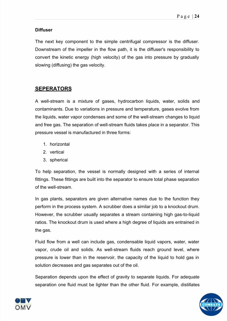
8102019 Gas sweetening Plant
httpslidepdfcomreaderfullgas-sweetening-plant 2862
P a g e | 24
Diffuser
The next key component to the simple centrifugal compressor is the diffuser
Downstream of the impeller in the flow path it is the diffusers responsibility to
convert the kinetic energy (high velocity) of the gas into pressure by gradually
slowing (diffusing) the gas velocity
SEPERATORS
A well-stream is a mixture of gases hydrocarbon liquids water solids and
contaminants Due to variations in pressure and temperature gases evolve from
the liquids water vapor condenses and some of the well-stream changes to liquid
and free gas The separation of well-stream fluids takes place in a separator This
pressure vessel is manufactured in three forms
1 horizontal
2 vertical
3 spherical
To help separation the vessel is normally designed with a series of internal
fittings These fittings are built into the separator to ensure total phase separation
of the well-stream
In gas plants separators are given alternative names due to the function they
perform in the process system A scrubber does a similar job to a knockout drum
However the scrubber usually separates a stream containing high gas-to-liquid
ratios The knockout drum is used where a high degree of liquids are entrained in
the gas
Fluid flow from a well can include gas condensable liquid vapors water water
vapor crude oil and solids As well-stream fluids reach ground level where
pressure is lower than in the reservoir the capacity of the liquid to hold gas in
solution decreases and gas separates out of the oil
Separation depends upon the effect of gravity to separate liquids For adequate
separation one fluid must be lighter than the other fluid For example distillates
8102019 Gas sweetening Plant
httpslidepdfcomreaderfullgas-sweetening-plant 2962
P a g e | 25
(gasoline kerosene etc) and crude oil will not separate in a vessel because they
tend to dissolve in each other Because a separator basically depends upon
gravity to separate the fluids the ease with which separation takes place
depends upon the difference in density of the fluids
Droplets of liquid will separate from gas provided
a) The gas remains in the separator long enough
b) The gas flow remains constant to provoke separation
The difference in density between a gas and liquid will therefore determine the
maximum flow rate of liquid in the vessel
Figure Two phase horizontal separator
Gas bubbles in the liquid will break out in some oil field applications in 30 to 60
seconds Consequently the separator is designed so that the liquid remains in
the vessel for 30 to 60 seconds The length of time that a liquid remains in the
vessel is called its residence time Residence time differs widely from field to field
depending upon viscosity and API Gravity
Another important factor which must be considered is temperature Generally a
decrease in operating temperature will increase the liquid recovery in a separator
8102019 Gas sweetening Plant
httpslidepdfcomreaderfullgas-sweetening-plant 3062
P a g e | 26
as the gas condenses By reducing the pressure on the fluid flash separation
occurs resulting in a flow through the separator which is controlled by external
instrumentation
COALESCENCE
Another important principle in fluid separation is that of coalescence This means
the coming together of liquid droplets created by the force of gravity
A common example of coalescing occurs when drops of water form on the
windshield of a car as it is driven in fog As the tiny drops or water which make up
the fog strike the windshield they combine and eventually form a drop large
enough to run down the glass
Several of the internal devices of a separator such as deflector plates
straightening vanes and even the vessel walls are forms of coalescers In each
vessel drops of liquid adhere to the surface of the device and combine with other
8102019 Gas sweetening Plant
httpslidepdfcomreaderfullgas-sweetening-plant 3162
P a g e | 27
drops until the drop is large enough to fall out The effectiveness of separation
will also depend upon the total amount of coalescing surface area that is present
There are many different types of separators used in the Oil amp Gas industry
Consequently separators are manufactured with one two or several internal
fittings depending on their use and quick removal of these fluids from the vessel
DEFLECTOR PLATES
These are fitted in front of the inlet to the separator and can be net or
dish-shaped Their purpose is to absorb the impact of the incoming fluids and to
encourage the separation of gas and liquids They also slow the flow rate of the
liquids through the vessel
WEIRS
A weir is a metal wall which is fitted across the inside of the vessel normally to a
height of 50 of the overall height of the separator Its purpose is to assist the
process of three phase separation The inlet fluids (oil plus water) are given time
to separate in the liquid accumulation section The water level (interface) is
normally controlled at 50 of the height of the weir Oil floating on the wateroverflows the weir and accumulates in the small oil compartment where it is
drawn off under level control
CENTRIFUGAL DEVICES
These are used in both vertical and horizontal separators for gas-liquid
separation The device imparts a swirling motion to the fluids entering the vessel
Centrifugal force causes the heavier liquids to travel outwards towards the walls
of the vessel and the lighter gases to flow up the centre Centrifugal devices are
also known as cyclones
VORTEX BREAKERS
When liquid flows through a drain outlet a vortex (whirlpool) will form This can
be seen when we pull the plug from a sink or bath tub The same would happen
as water and oil flow from the separator This condition a vortex could allow gas
to flow down the centre of the whirlpool and enter the liquid phase causing
8102019 Gas sweetening Plant
httpslidepdfcomreaderfullgas-sweetening-plant 3262
P a g e | 28
pressurizing of tanks etc To stop this happening vortex breakers are fitted to all
liquid outlets Although they come in a number of different designs vortex
breakers all serve the same purpose - to prevent a whirlpool from forming
MIST OR DEMISTER PADS
The gas which is released from the fluids in the separator still contains droplets of
oil and water which coalesce and fall when the drops get large enough The
demister pad assists in this process Made from knitted wire and contained within
a sturdy frame it causes the gas to continually change its direction of flow
Because gas changes direction far easier than liquid the gas will flow around
each strand of wire whilst the liquid entrained in the gas stream will continue and
stick to the wire
COALESCING PLATES
There are several different forms of coalescing devices the most common of
which are coalescing plates These plates are mounted in the flow stream of the
fluids and assist in breaking down oil-water emulsions The fluid is forced to
follow a path that constantly changes direction This causes the water droplets to
gather together or coalesce and fall to the bottom of the separator The same
principle is used to separate gas and oil mixtures when the oil droplets are
induced to coalesce Simply stated every surface within the separator including
the separator walls assists with the coalescing process
STRAIGHTENlNG VANES
These are often fitted to horizontal separators to remove turbulence in the gas
stream after initial separation at the inlet deflector
FLOAT SHEILD
Internal floats are used as level controllers Any agitation of the liquid surface or
the effect of coalesced liquids falling on the float may cause control problems
Therefore a float shield is fitted to enclose the float creating an area of still liquid
8102019 Gas sweetening Plant
httpslidepdfcomreaderfullgas-sweetening-plant 3362
P a g e | 29
MEMBRANES
The gas contains 12 carbon dioxide and 22 ppm of hydrogen sulphide at 115oF
and 1100 psig This needs to be removed before the gas can be exported The
majority of carbon dioxide hydrogen sulphide and water is removed by means of
membranes
Membranes are thin semipermeable barriers that selectively separate some
compounds from others Currently the only commercially workable membranes
used for CO2 removal are polymer based for example cellulose acetate
polyimides polyamides polysulfone polycarbonates and polyetherimide The
membrane does not operate as a filter where small molecules are separated
from larger ones through a medium with pores rather it separates based on how
well different compounds dissolve into the membrane and diffuse through it The
membranes are manufactured in flat sheets consisting of an extremely thin
nonporous layer mounted on a much-thicker and highly porous layer of the same
material providing mechanical strength The flat sheets are combined into a
spiral-wound element (Figure below) Feed gas enters along the side of the
membrane and passes through the feed spacers As the gas travels between
membrane sheets CO2 H2S and H2O permeate through the membrane and are
collected in the permeate tube The driving force for transport is the high-feed
pressure and low-permeate pressures The gas on the feed side that does not
permeate leaves through the side of the element opposite the feed position Once
the membranes have been manufactured into elements six to 12 elements are
joined together and inserted into a tube Multiple tubes are mounted on skids in a
horizontal orientation
8102019 Gas sweetening Plant
httpslidepdfcomreaderfullgas-sweetening-plant 3462
P a g e | 30
Figure Membrane general Working
In high H2S applications most polymers have been shown to have very little
resistance to H2S plasticization (ldquosofteningrdquo of the membrane) and as a
consequence can only be used at very low H2S partial pressure limits Cellulose
acetate membranes in contrast have been shown to be applicable at extreme
H2S partial pressure conditions It is these membranes that have been utilized in
the testing to determine the limits of membrane performance in high H 2S
applications
The primary membranes used in Kadanwari facility are Cellulose acetate
Cellulose acetic acid and acetic anhydride are mixed together and reacted to
form cellulose acetate polymers This process is aided by the addition of a small
amount of sulfuric acid which is subsequently neutralized during processing
However the membranes are bought from UOP (vendor) and installed for use
8102019 Gas sweetening Plant
httpslidepdfcomreaderfullgas-sweetening-plant 3562
P a g e | 31
How membrane work
The basic principle of separation is selectivity of certain components of a mixture
for the membrane For example the cellulose acetate membrane has very high
selectivity for CO2 and H2S as compared to CH4 Therefore such type of
membrane can be used in gas sweetening process
The selectivity is directly related to the Permeability of gas which accounts that
which gas can pass across the membrane more easily In simple words
membranes being polymer materials are made of long chains of molecules The
different structure of polymer materials only allow selective molecules to pass
through them depending upon chemical and physical compatibility Thus
permeability depends upon choice of polymer
The permeability is determined by permeability coefficient (P) and is product of
solubility (S) and diffusivity (D)
P = S D
Solubility
The solubility is mainly determined by ease of condensation Heavy molecules
are more readily condensed Therefore higher molecular weighted molecules will
more easily condensed and therefore have greater solubility
Molecule Molecular weight
CH4 16
H2S 34
CO2 44
8102019 Gas sweetening Plant
httpslidepdfcomreaderfullgas-sweetening-plant 3662
P a g e | 32
Diffusivity
Diffusivity is ease of molecule to penetrate into some material It depends on size
of gas molecule Here size of molecule is not to be confused by molecular weight
it is the size of the structure Eg the size of O2 molecule is smaller than N2
Molecule Molecular Diameter (Ao)
CO2 33
H2S 36
Ch4 40
For cellulose acetate
DCO2DCH4 S CO2S CH4 P CO2P CH4
45 73 308
Chemical degradation
Cellulose acetate polymer is chemically degraded by a process called hydrolysis
which means breaking apart by the addition of water This is a chemical reaction
in which water is added to the cellulose acetate polymer causing the release of
acetic acid molecules This process proceeds stepwise until all the acetate
groups are released resulting in the reformation of cellulose Moreover alcohols
aromatic hydrocarbons or solvents with chlorine nitro benzene or similar
aromatic solvents will harm the membrane It will expand and lose plastification in
contact with them
Effect of Temperature
The permeation rates of all gases increases with increasing temperature
however membrane selectivity for CO2 over hydrocarbon decreases at higher
8102019 Gas sweetening Plant
httpslidepdfcomreaderfullgas-sweetening-plant 3762
P a g e | 33
temperature Consequently CO2 removal will improve as operating temperature
increases but hydro carbon recovery will decrease
Primary Membrane
The primary membranes comprise of two trains Each train consists of two
sections AB and CD each section consists of a 30 tube membrane skid (A and
C) followed by a 25 tube skid (B and D) The conditioned gas (after pre-
treatment) enters the primary membrane via the particulate filter adjacent to the
skid The gas is fed to the membranes through a common inlet manifold which
supplies primary membranes skids A and C A pressure control loop located
upstream of the manual inlet isolation valve is provided to maintain a constant
supply pressure to the membrane skid and to allow for preheating at the inlet
prior to skid start-up This pressure control loop can also be used during start-up
to control the pressurization of the pretreatment skid and associated pipes to the
primary membranes
The gas passes through membrane skid A the residual gas exiting the membrane
skid is sent to skid B and the permeate to common permeate discharge header An
identical arrangement is provide on the inlet to skid C as provided on skid A Theresidual gas from skid B combines with the residual gas from skid D in a common
discharge header and is then sent to the H2S polishing towers via the feed coolers
on the pre-treatment skid The permeate from skid B is sent to the common
permeate discharge header The permeate discharge header sends the gas to
either the recycle compressor or the vent header via a pressure control loop
Overpressure protection for the membranes is provided by a pressure safety valve
on the supply header to the membrane banks
8102019 Gas sweetening Plant
httpslidepdfcomreaderfullgas-sweetening-plant 3862
P a g e | 34
Secondary (Recycle) Membrane
The recycle membranes comprise of a single train with two skids each with four
banks of membrane tubes The conditioned gas from the discharge of the recycle
pre-treatment skid is routed to the first recycle membrane skid The gas passes
through the membranes the residual gas is fed to primary membrane (skid A) inlet
via feed gas cooler and permeate to the common permeate discharge header An
identical arrangement is provide on the inlet to skid B Permeate from the recycle
membrane skids A and B is routed to the vent header Some portion of permeate is
heated and sent for regeneration in Mem-Guard units Nitrogen purge can be
connected downstream of the inlet isolation valve on each skid to enable the
membrane tubes to be purged and left pressurized during prolonged shutdown
8102019 Gas sweetening Plant
httpslidepdfcomreaderfullgas-sweetening-plant 3962
P a g e | 35
Figure Flow Diagram of Recycle membrane unit
8102019 Gas sweetening Plant
httpslidepdfcomreaderfullgas-sweetening-plant 4062
P a g e | 36
ADVANTAGES OF MEMBRANE SYSTEMS
Membrane systems have major advantages over more-traditional methods of
acid gas removal
Lower capital cost Membrane systems are skid mounted and so the
scope cost and time taken for site preparation are minimal Installation
costs are significantly lower than alternative technologies especially for
remote areas Furthermore no additional facilities for solvent storage and
water treatment needed by other processes are required
Lower operating costs The only major operating cost for single-stage
membrane systems is membrane replacement This cost is significantly
lower than the solvent replacement and energy costs associated with
traditional technologies The improvements in membrane and
pretreatment design allow a longer useful membrane life which further
reduces operating costs The energy costs of multistage systems with
large recycle compressors are usually comparable to those for traditionaltechnologies
Deferred capital investment Often contracted sales-gas flow rates
increase over time as more wells are brought on-line With traditional
technologies the system design needs to take this later production into
account immediately and so the majority of the equipment is installed
before it is even needed The modular nature of membrane systems
means that only the membranes that are needed at start-up need be
installed The rest can be added either into existing tubes or in new skids
only when they are required
Operational simplicity and high reliability Because single-stage
membrane systems have no moving parts they have almost no
8102019 Gas sweetening Plant
httpslidepdfcomreaderfullgas-sweetening-plant 4162
P a g e | 37
unscheduled downtime and are extremely simple to operate They can
operate unattended for long periods of time The addition of a recycle
compressor adds some complexity to the system but still much less than
with a solvent- or adsorbent-based technology Multistage systems can be
operated at full capacity as single-stage systems when the recycle
compressor is down
Good weight and space efficiency Skid construction can be optimized
to the space available This space efficiency is especially important for
offshore environments where deck area is at a premium and is the
reason why so many new offshore developments have chosen to use
membranes for acid gas removal Figure 6 illustrates the space efficiency
of membrane systems The membrane unit in the lower left corner
replaced all the amine and glycol plant equipment shown in the rest of the
picture
Adaptability Because membrane area is dictated by the percentage of
acid gas removal rather than absolute acid gas removal small variations
in feed acid gas content hardly change the sales-gas acid gas
specification For example a system designed for 10 down to 3 acid
gas removal produces a 35 product from a 12 feed gas and a 5
product from a 15 feed gas
Design efficiency The membrane and pretreatment systems integrate a
number of operations such as dehydration CO2 and H2S removal dew-
point control and mercury removal Traditional acid gas removal
technologies require all of these operations as separate processes and
may also require additional dehydration because some technologies
saturate the product stream with water
8102019 Gas sweetening Plant
httpslidepdfcomreaderfullgas-sweetening-plant 4262
P a g e | 38
Power generation The permeate gas from membrane systems can be
used to provide fuel gas for power generation either for a recycle
compressor or other equipment
Ideal for debottlenecking Because expanding solvent- or adsorbent-
based acid gas removal plants without adding additional trains is difficult
an ideal solution is to use membranes for bulk acid gas removal and leave
the existing plant for final cleanup An additional advantage is that the
permeate gas from the membrane system can often be used as fuel for
the existing plant thus avoiding significant increase in hydrocarbon
losses
Environmentally friendly Membrane systems do not involve the
periodic removal and handling of spent solvents or adsorbents Permeate
gases can be flared used as fuel or re-injected into the well Items thatdo need disposal such as spent membrane elements can be incinerated
Ideal for remote locations Many of the factors mentioned above make
membrane systems a highly desirable technology for remote locations
where spare parts are rare and labor unskilled Furthermore solvents
storage and trucking water supply power generation or extensive
infrastructure are not required
Re-injection optimizations Since the permeate stream from the
membrane system can be operated at elevated pressures it is possible to
further pressurize by re-injection compression train
8102019 Gas sweetening Plant
httpslidepdfcomreaderfullgas-sweetening-plant 4362
P a g e | 39
Sorption
Sorption is a physical and chemical process by which one substance becomes
attached to another
It is of two main types
1 Absorption
2 Adsorption
Absorption
Absorption is a physical or chemical phenomenon or process in which atoms
molecules or ions enter some bulk phase ndash gas liquid or solid material This is a
different process from adsorption since molecules undergoing absorption are
taken up by the volume not by the surface (as in the case for adsorption)
Absorption process may be chemical (reactive) or physical (non-reactive)
Physical absorption
Physical absorption or non-reactive absorption is made between two phases ofmatter a liquid absorbs a gas or a solid absorbs a liquid
When a liquid solvent absorbs a gas mixture or part of it a mass of gas moves
into the liquid For example water may absorb oxygen from the air This mass
transfer takes place at the interface between the liquid and the gas at a rate
depending on both the gas and the liquid This type of absorption depends on the
solubility of gases the pressure and the temperature The rate and amount of
absorption also depend on the surface area of the interface and its duration in
time
When a solid absorbs a liquid mixture or part of it a mass of liquid moves into the
solid For example a clay pot used to store water may absorb some of the water
This mass transfer takes place at the interface between the solid and the liquid
at a rate depending on both the solid and the liquid
8102019 Gas sweetening Plant
httpslidepdfcomreaderfullgas-sweetening-plant 4462
P a g e | 40
Chemical absorption
Chemical absorption or reactive absorption is a chemical reaction between the
absorbed and the absorbing substances Sometimes it combines with physical
absorption This type of absorption depends upon the stoichiometry of the
reaction and the concentration of its reactants
Adsorption
Adsorption is the adhesion of atoms ions or molecules from a gas liquid or
dissolved solid to a surface This process creates a film of the adsorbate on the
surface of the adsorbent The binding to the surface is usually weak and
reversible Compounds with color and those that have taste or odor tend to bind
strongly Compounds that vibrate at frequencies in the visible spectrum are very
often are strongly adsorbed on activated carbon
The most common industrial adsorbents are activated carbon silica gel and
alumina because they present enormous surface areas per unit weight
Depending on the nature of attractive forces existing between the adsorbate and
adsorbent adsorption can be classified as
i) Physical adsorption
ii) Chemical adsorption
i) Physical adsorption (Physisorption)
In physical adsorption the forces of attraction between the molecules of the
adsorbate and the adsorbent are of the weak van der Waals type Since the
forces of attraction are weak the process of physisorption can be easily reversed
by heating or decreasing the pressure of the adsorbate (as in the case of gases)
8102019 Gas sweetening Plant
httpslidepdfcomreaderfullgas-sweetening-plant 4562
P a g e | 41
ii) Chemical adsorption (Chemisorption)
In chemisorption the forces of attraction between the adsorbate and the
adsorbent are very strong the molecules of adsorbate form chemical bonds with
the molecules of the adsorbent present in the surface
Adsorption is generally accompanied by release of energy that is most
adsorption processes are exothermic in nature Adsorption is a spontaneous
process therefore its free energy change is negative (∆Glt0) However the
entropy change associated with adsorption is generally negative because the
adsorbate molecules lose their translation freedom when they get attached to the
surface of the adsorbent Therefore in order for ∆G to be negative the enthalpy
change (∆H) must be sufficiently negative such that (∆G=∆H-T∆S) lt 0 This
explanation accounts for exothermic adsorption processes In cases where
endothermic adsorption occurs the entropy change ∆S is sufficiently positive
such that ∆G remains negative
Pre treatment
The main function of pretreatment skid is to provide membrane inlet specification
gas as mentioned by the vendor UOP It removes the contaminants that would
poison the membranes like dust solids (adsorbent particles) lube oil heavy
hydrocarbons etc It consists of
Feed Cooler
Feed Gas Scrubber
Filter Coalescer
Feed Gas Heater
Activated Carbon Guard Filter
Particle Filter
8102019 Gas sweetening Plant
httpslidepdfcomreaderfullgas-sweetening-plant 4662
8102019 Gas sweetening Plant
httpslidepdfcomreaderfullgas-sweetening-plant 4762
P a g e | 43
The regeneration is carried out by heated permeate gas from the recycle
membranes at 450oF The vessel is depressurized to 20 psi and heated gas is
introduced from top The gas carries out the adsorbed contaminants and leaves
the vessel from bottom cleaning the adsorbent This contaminated gas is burnt in
the flare
UOP the vendor of Memguard unit has never disclosed that what substance
MG3 and MG5 exactly are But as mentioned by vendor that both care class of
aluminosilicates Therefore MG3 can be potassium aluminosilicate and MG5 can
be Calcium aluminosilicate These are molecular sieves adsorbents Molecular
sieves are a microporous material which can selectively adsorb gases andliquids They are synthetic zeolites (crystalline metal aluminosilicates) which
upon dehydration can efficiently and selectively remove water or other
solvents The selectivity of a molecular sieve is determined by its pore size
molecules with a critical diameter which is less than the pore size will be
efficiently adsorbed while larger molecules will be excluded
8102019 Gas sweetening Plant
httpslidepdfcomreaderfullgas-sweetening-plant 4862
P a g e | 44
3A Molecular Sieve Adsorbent
The 3A molecular sieve adsorbent has a 3 angstrom (3A) pore size which means
that any molecule that is larger than the 3 angstrom pores will not be adsorbed
The 3A molecular sieve is the potassium type of A crystalline structure and is a
form of alkali Aluminosilicate For a 3A molecular sieve the sequence rate that
adsorption occurs is He Ne N and H2O
Due to the crystalline structure molecular sieves that have a 3 angstrom pore
size have a very high rate of adsorption and properties that promote a longer life
for products treated by the sieve The most common use for the 3A molecular
sieve is to remove water and moisture from materials that are in gas and liquid
form
5A Molecular Sieve Adsorbent
These are molecular sieve adsorbents with a pore size of 5 angstrom (5A) 5A
molecular sieves are unable to adsorb any molecules or impurities that are
smaller than 5A It is calcium form of type A crystalline structure and is form of analkali-aluminosilicate that is most commonly used to separate isomerous alkanes
from normal alkanes and to co-adsorb moisture and water along with carbon
dioxide from gases In additional 5A molecular sieves are used for gaseous
pressure swing adsorption (PSA)mdashthat is to separate particular gases from other
gases
Adsorption of nC4H10
Adsorption of nC4H10
Adsorption of C3H8 to C22H46
Adsorption of Freon-12 (dichlorodifluoromethane)
Natural gas drying
Normal- and iso-paraffin separation
Separation of aromatic
8102019 Gas sweetening Plant
httpslidepdfcomreaderfullgas-sweetening-plant 4962
P a g e | 45
Inlet Composition of Memguard vessel
COMPSOSITION MOLE
CARBON DIOXIDE 1096
MEHTANE 8593
ETHANE 173
PROPANE 023
I-BUTANE 008
N BUTANE 004
PENTANES 004
HEXANE + 000
NITROGEN 076
WATER 007
Outlet Composition of Memguard vessel
COMPSOSITION MOLE
CARBON DIOXIDE 1098
MEHTANE 8608
ETHANE 173
PROPANE 023
I-BUTANE 008N BUTANE 004
PENTANES 004
HEXANE + 000
NITROGENT 076
WATER 000
H2S polisher
The H2S polishing unit has been designed to treat 187 MMscfday of natural gas
containing up to 11 CO2 and 21 ppm H2S where the level of the CO2 and H2S
is reduced using a MemGuard Membrane separation unit The unit is situated
down-stream of the membrane unit and will further reduce the level of H2S in the
processed gas to a sales gas specification of 38 ppm
8102019 Gas sweetening Plant
httpslidepdfcomreaderfullgas-sweetening-plant 5062
P a g e | 46
This process uses three non-regenerable fixed bed absorber vessels using a low
temperature high activity absorbent The absorbent is a mixture of activated
metal oxides (mainly zinc oxide) The three towers can are generally operated in
parallel arrangement but on demand can be used in series (any of alternate
arrangements of A B C vessels) as shown in figure
The higher sales gas flow rate increased the catalyst consumption and
replacement frequency
ZnO + H2S =gt ZnS + H20
Routine samples are taken from the beds to provide a check on each bed
performance and to follow the saturation profile during the absorbent life After
the adsorbent has been fully utilized the adsorption vessels are recharged with
new adsorbent discarding the utilized one in a safe manner
109oF
1215 psig
Before H2S Polishing After H2S Polishing
8102019 Gas sweetening Plant
httpslidepdfcomreaderfullgas-sweetening-plant 5162
P a g e | 47
Figure
H2S Tower
Inlet pipe
4 Drums of 19mm
ceramic Balls
6 Micron mesh
5 Drums of 50mmceramic
1 Drums of19mm ceramic
01 Drums of6mm ceramic
112 drums of
Catalist ZnO
8102019 Gas sweetening Plant
httpslidepdfcomreaderfullgas-sweetening-plant 5262
P a g e | 48
Recycle Compressor
The permeate gas of the primary membrane unit carries recoverable amount of
CH4 It is fed to recycle membrane unit for further CH 4 recovery But the
permeate pressure from primary membranes which has been reduced to 12 psi
must be regenerated to 1200 psi for the gas to be fed again to the system For
this purpose we have employed recycle compressor The compressor is a four
stage centrifugal compressor It is driven by gas turbine of 31200 HP It has 25
MW producing capacity
Figure Recycle Compressor Process Flow Diagram
8102019 Gas sweetening Plant
httpslidepdfcomreaderfullgas-sweetening-plant 5362
P a g e | 49
Sales Gas Compressor
Gas from H2S polishing unit is sent to sales gas compressor where its pressure
is enhanced to 1100 psi so it may be injected to SNGPL high pressure trunk line
Sales gas compressor is single stage gas turbine driven
Figure Process Flow of Sales Gas Compressor
8102019 Gas sweetening Plant
httpslidepdfcomreaderfullgas-sweetening-plant 5462
P a g e | 50
Cooling Towers
A cooling tower is a heat rejection device which extracts waste heat to theatmosphere through the cooling of a water stream to a lower temperature Hot
water from the system enters the cooling tower and is distributed over the fill
(heat transfer surface) Air is induced or forced through the fill causing a small
portion of the water to evaporate This evaporation removes heat from the
remaining water which is collected in the cold water basin and returned to the
system to absorb more heat Each cooling tower line although operating under
the same basic principle of operation is arranged a little differently
Types
Natural draft mdash Utilizes buoyancy via a tall chimney Warm moist air naturally
rises due to the density differential compared to the dry cooler outside air Warm
moist air is less dense than drier air at the same pressure This moist air
buoyancy produces an upwards current of air through the tower
Mechanical draft mdash Uses power-driven fan motors to force or draw airthrough the tower
o Induced draft mdash A mechanical draft tower with a fan at the
discharge (at the top) which pulls air up through the tower The fan
induces hot moist air out the discharge This produces low entering
and high exiting air velocities reducing the possibility of
recirculation in which discharged air flows back into the air intake
o Forced draft mdash A mechanical draft tower with a blower type fan at
the intake The fan forces air into the tower creating high entering
and low exiting air velocities The low exiting velocity is much more
susceptible to recirculation This fanfill geometry is also known as
blow-through
8102019 Gas sweetening Plant
httpslidepdfcomreaderfullgas-sweetening-plant 5562
P a g e | 51
Forced Draft Cooling Tower Vs Induced Draft Cooling Tower
Induced Draft Cooling Tower have the ability to handle large water flow
rate than Forced Draft Cooling Tower
Induced Draft Cooling Tower is suitable for large cell sizes and fan sizes
as compared with Forced Draft Larger fan size may result in greater
efficiency and consequently lower power and sound level
Forced Draft Cooling Tower can be square or rectangular type only
however Induced Draft Cooling Towers can be round square or
rectangular type
Induced Draft Cooling Tower uses more compact ground area than Forced
Draft Cooling Tower equivalent capacity due to absence of fan on one
side
Fan equipment is warm exhaust air is less liable to icing up in winter
operation (Cold Countries)
Higher velocity in Forced Draft Cooling Tower cause drop in suspension
and cause additional static resistance to system
Configuration
There are two main configurations of factory assembled cooling towers crossflow
and counterflow In crossflow cooling towers the water flows vertically down the
fill as air flows horizontally across In counterflow cooling towers the water flows
vertically down the fill as air flows vertically up
Crossflow Configuration Counterflow Configuration
8102019 Gas sweetening Plant
httpslidepdfcomreaderfullgas-sweetening-plant 5662
P a g e | 52
Drift mdash Water droplets that are carried out of the cooling tower with the exhaust
air Drift droplets have the same concentration of impurities as the water entering
the tower The drift rate is typically reduced by employing baffle-like devices
called drift eliminators through which the air must travel after leaving the fill and
spray zones of the tower
Blow-out mdash Water droplets blown out of the cooling tower by wind generally at
the air inlet openings Water may also be lost in the absence of wind through
splashing or misting Devices such as wind screens louvers splash deflectors
and water diverters are used to limit these losses
Blow-down mdash The portion of the circulating water flow that is removed (usually
discharged to a drain) in order to maintain the amount of Total Dissolved Solids
(TDS) and other impurities at an acceptably low level Higher TDS concentration
in solution may result from greater cooling tower efficiency However the higher
the TDS concentration the greater the risk of scale biological growth and
corrosion
Make-up mdash The water that must be added to the circulating water system in
order to compensate for water losses such as evaporation drift loss blow-out
blow-down etc
Approach mdash The approach is the difference in temperature between the cooled-
water temperature and the entering-air wet bulb temperature
Range mdash The range is the temperature difference between the warm water inlet
and cooled water exit
Fill mdash Inside the tower fills are added to increase contact surface as well as
contact time between air and water to provide better heat transfer The efficiency
of the tower depends on the selection and amount of fill
8102019 Gas sweetening Plant
httpslidepdfcomreaderfullgas-sweetening-plant 5762
P a g e | 53
There are two types of fills that may be used
o Film type fill (causes water to spread into a thin film)
o Splash type fill (breaks up falling stream of water and interrupts its
vertical progress)
Important
Scale build up is controlled by adding chemicals to the cooling loop and diluting
the concentration by blow down and make-up Following chemicals are added to
the Cooling to control CorrosionSale and microbial growth
Corrosion Inhibitor To control corrosion in the Cooling system
Dispersant To kept ions in suspension to avoid settle down and buildup
Sodium hypo Chlorite To Control microbial Growth
Acid To control Alkalinity in the system
High Stress Polymer To run the system at higher conductivity It is a
multifunctional polymer for Zinc amp Phosphate stabilization in cooling tower
Fin Fan Cooler
Fin fan heat exchanger is simply a pressure vessel which cools a circulating fluid
within finned tubes by forcing ambient air over the exterior of the tubes A
common example of an air cooler is a carrsquos radiator Fin Fan Coolers are used in
any application where large quantities of heat need to be transferred This
includes chemical and petrochemical industries power stations waste-to-energy
facilities as well as steelworks
Fin Fan Cooler are used for two primary reasons
They increase plant efficiency
They are a green solution as compared to cooling towers and shell and
tube heat exchangers because they do not require an auxiliary water
8102019 Gas sweetening Plant
httpslidepdfcomreaderfullgas-sweetening-plant 5862
P a g e | 54
supply (water lost due to drift and evaporation plus no water treatment
chemicals are required)
Figure General Overview of Fin Fan Cooler
Produced Water
The produced water system receives liquid from the equipment Miano slug
catcher train 1 and 2 inlet separators and is fed to three phase separator where
water oil and gas is separated The gases produced are burnt in incinerator
whereas hydrocarbon liquid is stored to be sold Liquid from compressors
recycle inlet separator recycle feed scrubber high and low pressure slug
catchers is passed to degasser Separated water is injected down the earth
Incinerator
The term incinerate means to burn something until nothing is left but ashes An
incinerator is a unit or facility used to burn trash and other types of waste until it is
reduced to ash An incinerator is constructed of heavy well-insulated materials
so that it does not give off extreme amounts of external heat The high levels of
heat are kept inside the furnace or unit so that the waste is burned quickly and
efficiently If the heat were allowed to escape the waste would not burn as
completely or as rapidly
8102019 Gas sweetening Plant
httpslidepdfcomreaderfullgas-sweetening-plant 5962
P a g e | 55
Control System
The plant is controlled at CCR (Central Control Room) by PLCs (Programmable
Logic Controllers) through fiber optic control line All control parameters are
received at LER (Local Equipment Room) via two optic fiber control lines One
being primary and other secondary operating in redundancy ie if primary fails
control shifts to secondary These control parameters are sent to CCR via single
optic fiber cable
Safety System
Wellheads and Gas Processing Plant have their own Fire amp Gas detection
systems emergency shutdown (ESD) Plant has a fault tolerant controller It is
based on Triple Modular Redundant (TMR) architecture manufactured by
Triconex The TMR system is based on three isolated parallel control systems
integrated into one system The system operates on a two out of three voting
principle which provides high integrity error free uninterrupted operation with no
single point of failure The TMR receives inputs from Process Sensors Manual
Switches Fire amp Gas Detectors Packaged Equipment Control Systems and
Product Exporting Facilities The TMR carries out cause and effect processing on
the data received and where necessary produces output signals Outputs from
the TMR are hard wired directly to ESD shutdown and blow down valve
solenoids motor control instrumentelectrical interfaces to control electrical
drives package equipment logic control systems manifold area as well as
telecoms
The operator in central control room is able to accept alarms and once the fault
has been cleared reset the input All the control systems are centralized to a
single interface All the PLCs (Programmable Logic Controllers) communicate with
the servers and servers communicate with the clients through Ethernet connectivity
Centralization eases the navigation of different systems at a common interface
Emergency Shutdown
The ESD system receives inputs from field mounted instrumentation on the process
8102019 Gas sweetening Plant
httpslidepdfcomreaderfullgas-sweetening-plant 6062
P a g e | 56
and utility equipment and initiates executive actions appropriate to the level of ESD
The system is an Active system which is in standby and will activate when in an
alarm or fault condition The Kadanwari Gas Process Facility ESD system is
comprised of five (5) levels The emergency severity decreases with increasing ESD
level number
ESD 1
This shutdown level is automatically initiated by fire major gas leak or a detected
toxic atmosphere in the process area of the plant or manually from CCR A level 1
shutdown will cause all production to cease close all emergency shutdown
valves stop the process and shutdown of the main power generation The
emergency vent valves to the stack will open and in addition all equipment of zone 1
certified will be isolated This is the highest level of ESD and will cause the following
to occur
All Shutdown Valves (SDVs) on the process facility will close All slowdown Valves (BDVs) on the process facility will open
All Main Gas Driven Generators will be tripped
Emergency Diesel Generator will start
All electrical power to process and utility rotating equipment will be
isolated
Wellhead Choke Valves Close Wing Valves Close Upper Master Valve
(UMV) Close
ESD 2
This shutdown level is activated automatically if a major process or utility failure
occurs or manually from CCR All production to the plant from the wellhead is
stopped All emergency shutdown valves trip to their fail safe position
Venting shall be as specified This level of ESD will cause the following to occur
8102019 Gas sweetening Plant
httpslidepdfcomreaderfullgas-sweetening-plant 6162
P a g e | 57
All Shutdown Valves (SDVs) on the process facility will close
All electrical power to process and utility rotating equipment will be
isolated
Wellhead Choke Valve Close Wing Valves Close and Upper Master Valve(UMV) Close
ESD 3
The level 3 shutdown isolates and stops a single process train only Production
continues via the other train This ESD level is initiated by process conditions or
operator at local panel This level of ESD will cause the following to occur
ESD 3A Train 1 production to cease
ESD 3B Train 2 production to cease
All online wellhead choke valves go to minimum flow ie (1O )
ESD 4
A level 4 shutdown shall cease all production from an entire field either
Kadanwari or Miano upstream of the associated slug catchers ESD 4K for
Kadanwari amp ESD 4M for Miano This ESD level is initiated automatically by slug
catcher abnormal process conditions This level of ESD will cause the following
to occur
All SDVs close isolating the relevant slug catcher and its upstream gas
production facility from the Kadanwari Gas Processing Plant
All Wellhead Choke Valves Close Wing Valves Close and Upper MasterValves (UMV) of the relevant gas production facility Close
A parallel timer is provided to close within 10 second if not closed in given
time SSSV seals the well
ESD 5
A level 5 shutdown represents equipment shutdown for the protection of the
individual equipment without any change in the process This level of ESD is for the
protection of various pieces of equipment and is initiated by its own inputs eg
8102019 Gas sweetening Plant
httpslidepdfcomreaderfullgas-sweetening-plant 6262
8102019 Gas sweetening Plant
httpslidepdfcomreaderfullgas-sweetening-plant 2962
P a g e | 25
(gasoline kerosene etc) and crude oil will not separate in a vessel because they
tend to dissolve in each other Because a separator basically depends upon
gravity to separate the fluids the ease with which separation takes place
depends upon the difference in density of the fluids
Droplets of liquid will separate from gas provided
a) The gas remains in the separator long enough
b) The gas flow remains constant to provoke separation
The difference in density between a gas and liquid will therefore determine the
maximum flow rate of liquid in the vessel
Figure Two phase horizontal separator
Gas bubbles in the liquid will break out in some oil field applications in 30 to 60
seconds Consequently the separator is designed so that the liquid remains in
the vessel for 30 to 60 seconds The length of time that a liquid remains in the
vessel is called its residence time Residence time differs widely from field to field
depending upon viscosity and API Gravity
Another important factor which must be considered is temperature Generally a
decrease in operating temperature will increase the liquid recovery in a separator
8102019 Gas sweetening Plant
httpslidepdfcomreaderfullgas-sweetening-plant 3062
P a g e | 26
as the gas condenses By reducing the pressure on the fluid flash separation
occurs resulting in a flow through the separator which is controlled by external
instrumentation
COALESCENCE
Another important principle in fluid separation is that of coalescence This means
the coming together of liquid droplets created by the force of gravity
A common example of coalescing occurs when drops of water form on the
windshield of a car as it is driven in fog As the tiny drops or water which make up
the fog strike the windshield they combine and eventually form a drop large
enough to run down the glass
Several of the internal devices of a separator such as deflector plates
straightening vanes and even the vessel walls are forms of coalescers In each
vessel drops of liquid adhere to the surface of the device and combine with other
8102019 Gas sweetening Plant
httpslidepdfcomreaderfullgas-sweetening-plant 3162
P a g e | 27
drops until the drop is large enough to fall out The effectiveness of separation
will also depend upon the total amount of coalescing surface area that is present
There are many different types of separators used in the Oil amp Gas industry
Consequently separators are manufactured with one two or several internal
fittings depending on their use and quick removal of these fluids from the vessel
DEFLECTOR PLATES
These are fitted in front of the inlet to the separator and can be net or
dish-shaped Their purpose is to absorb the impact of the incoming fluids and to
encourage the separation of gas and liquids They also slow the flow rate of the
liquids through the vessel
WEIRS
A weir is a metal wall which is fitted across the inside of the vessel normally to a
height of 50 of the overall height of the separator Its purpose is to assist the
process of three phase separation The inlet fluids (oil plus water) are given time
to separate in the liquid accumulation section The water level (interface) is
normally controlled at 50 of the height of the weir Oil floating on the wateroverflows the weir and accumulates in the small oil compartment where it is
drawn off under level control
CENTRIFUGAL DEVICES
These are used in both vertical and horizontal separators for gas-liquid
separation The device imparts a swirling motion to the fluids entering the vessel
Centrifugal force causes the heavier liquids to travel outwards towards the walls
of the vessel and the lighter gases to flow up the centre Centrifugal devices are
also known as cyclones
VORTEX BREAKERS
When liquid flows through a drain outlet a vortex (whirlpool) will form This can
be seen when we pull the plug from a sink or bath tub The same would happen
as water and oil flow from the separator This condition a vortex could allow gas
to flow down the centre of the whirlpool and enter the liquid phase causing
8102019 Gas sweetening Plant
httpslidepdfcomreaderfullgas-sweetening-plant 3262
P a g e | 28
pressurizing of tanks etc To stop this happening vortex breakers are fitted to all
liquid outlets Although they come in a number of different designs vortex
breakers all serve the same purpose - to prevent a whirlpool from forming
MIST OR DEMISTER PADS
The gas which is released from the fluids in the separator still contains droplets of
oil and water which coalesce and fall when the drops get large enough The
demister pad assists in this process Made from knitted wire and contained within
a sturdy frame it causes the gas to continually change its direction of flow
Because gas changes direction far easier than liquid the gas will flow around
each strand of wire whilst the liquid entrained in the gas stream will continue and
stick to the wire
COALESCING PLATES
There are several different forms of coalescing devices the most common of
which are coalescing plates These plates are mounted in the flow stream of the
fluids and assist in breaking down oil-water emulsions The fluid is forced to
follow a path that constantly changes direction This causes the water droplets to
gather together or coalesce and fall to the bottom of the separator The same
principle is used to separate gas and oil mixtures when the oil droplets are
induced to coalesce Simply stated every surface within the separator including
the separator walls assists with the coalescing process
STRAIGHTENlNG VANES
These are often fitted to horizontal separators to remove turbulence in the gas
stream after initial separation at the inlet deflector
FLOAT SHEILD
Internal floats are used as level controllers Any agitation of the liquid surface or
the effect of coalesced liquids falling on the float may cause control problems
Therefore a float shield is fitted to enclose the float creating an area of still liquid
8102019 Gas sweetening Plant
httpslidepdfcomreaderfullgas-sweetening-plant 3362
P a g e | 29
MEMBRANES
The gas contains 12 carbon dioxide and 22 ppm of hydrogen sulphide at 115oF
and 1100 psig This needs to be removed before the gas can be exported The
majority of carbon dioxide hydrogen sulphide and water is removed by means of
membranes
Membranes are thin semipermeable barriers that selectively separate some
compounds from others Currently the only commercially workable membranes
used for CO2 removal are polymer based for example cellulose acetate
polyimides polyamides polysulfone polycarbonates and polyetherimide The
membrane does not operate as a filter where small molecules are separated
from larger ones through a medium with pores rather it separates based on how
well different compounds dissolve into the membrane and diffuse through it The
membranes are manufactured in flat sheets consisting of an extremely thin
nonporous layer mounted on a much-thicker and highly porous layer of the same
material providing mechanical strength The flat sheets are combined into a
spiral-wound element (Figure below) Feed gas enters along the side of the
membrane and passes through the feed spacers As the gas travels between
membrane sheets CO2 H2S and H2O permeate through the membrane and are
collected in the permeate tube The driving force for transport is the high-feed
pressure and low-permeate pressures The gas on the feed side that does not
permeate leaves through the side of the element opposite the feed position Once
the membranes have been manufactured into elements six to 12 elements are
joined together and inserted into a tube Multiple tubes are mounted on skids in a
horizontal orientation
8102019 Gas sweetening Plant
httpslidepdfcomreaderfullgas-sweetening-plant 3462
P a g e | 30
Figure Membrane general Working
In high H2S applications most polymers have been shown to have very little
resistance to H2S plasticization (ldquosofteningrdquo of the membrane) and as a
consequence can only be used at very low H2S partial pressure limits Cellulose
acetate membranes in contrast have been shown to be applicable at extreme
H2S partial pressure conditions It is these membranes that have been utilized in
the testing to determine the limits of membrane performance in high H 2S
applications
The primary membranes used in Kadanwari facility are Cellulose acetate
Cellulose acetic acid and acetic anhydride are mixed together and reacted to
form cellulose acetate polymers This process is aided by the addition of a small
amount of sulfuric acid which is subsequently neutralized during processing
However the membranes are bought from UOP (vendor) and installed for use
8102019 Gas sweetening Plant
httpslidepdfcomreaderfullgas-sweetening-plant 3562
P a g e | 31
How membrane work
The basic principle of separation is selectivity of certain components of a mixture
for the membrane For example the cellulose acetate membrane has very high
selectivity for CO2 and H2S as compared to CH4 Therefore such type of
membrane can be used in gas sweetening process
The selectivity is directly related to the Permeability of gas which accounts that
which gas can pass across the membrane more easily In simple words
membranes being polymer materials are made of long chains of molecules The
different structure of polymer materials only allow selective molecules to pass
through them depending upon chemical and physical compatibility Thus
permeability depends upon choice of polymer
The permeability is determined by permeability coefficient (P) and is product of
solubility (S) and diffusivity (D)
P = S D
Solubility
The solubility is mainly determined by ease of condensation Heavy molecules
are more readily condensed Therefore higher molecular weighted molecules will
more easily condensed and therefore have greater solubility
Molecule Molecular weight
CH4 16
H2S 34
CO2 44
8102019 Gas sweetening Plant
httpslidepdfcomreaderfullgas-sweetening-plant 3662
P a g e | 32
Diffusivity
Diffusivity is ease of molecule to penetrate into some material It depends on size
of gas molecule Here size of molecule is not to be confused by molecular weight
it is the size of the structure Eg the size of O2 molecule is smaller than N2
Molecule Molecular Diameter (Ao)
CO2 33
H2S 36
Ch4 40
For cellulose acetate
DCO2DCH4 S CO2S CH4 P CO2P CH4
45 73 308
Chemical degradation
Cellulose acetate polymer is chemically degraded by a process called hydrolysis
which means breaking apart by the addition of water This is a chemical reaction
in which water is added to the cellulose acetate polymer causing the release of
acetic acid molecules This process proceeds stepwise until all the acetate
groups are released resulting in the reformation of cellulose Moreover alcohols
aromatic hydrocarbons or solvents with chlorine nitro benzene or similar
aromatic solvents will harm the membrane It will expand and lose plastification in
contact with them
Effect of Temperature
The permeation rates of all gases increases with increasing temperature
however membrane selectivity for CO2 over hydrocarbon decreases at higher
8102019 Gas sweetening Plant
httpslidepdfcomreaderfullgas-sweetening-plant 3762
P a g e | 33
temperature Consequently CO2 removal will improve as operating temperature
increases but hydro carbon recovery will decrease
Primary Membrane
The primary membranes comprise of two trains Each train consists of two
sections AB and CD each section consists of a 30 tube membrane skid (A and
C) followed by a 25 tube skid (B and D) The conditioned gas (after pre-
treatment) enters the primary membrane via the particulate filter adjacent to the
skid The gas is fed to the membranes through a common inlet manifold which
supplies primary membranes skids A and C A pressure control loop located
upstream of the manual inlet isolation valve is provided to maintain a constant
supply pressure to the membrane skid and to allow for preheating at the inlet
prior to skid start-up This pressure control loop can also be used during start-up
to control the pressurization of the pretreatment skid and associated pipes to the
primary membranes
The gas passes through membrane skid A the residual gas exiting the membrane
skid is sent to skid B and the permeate to common permeate discharge header An
identical arrangement is provide on the inlet to skid C as provided on skid A Theresidual gas from skid B combines with the residual gas from skid D in a common
discharge header and is then sent to the H2S polishing towers via the feed coolers
on the pre-treatment skid The permeate from skid B is sent to the common
permeate discharge header The permeate discharge header sends the gas to
either the recycle compressor or the vent header via a pressure control loop
Overpressure protection for the membranes is provided by a pressure safety valve
on the supply header to the membrane banks
8102019 Gas sweetening Plant
httpslidepdfcomreaderfullgas-sweetening-plant 3862
P a g e | 34
Secondary (Recycle) Membrane
The recycle membranes comprise of a single train with two skids each with four
banks of membrane tubes The conditioned gas from the discharge of the recycle
pre-treatment skid is routed to the first recycle membrane skid The gas passes
through the membranes the residual gas is fed to primary membrane (skid A) inlet
via feed gas cooler and permeate to the common permeate discharge header An
identical arrangement is provide on the inlet to skid B Permeate from the recycle
membrane skids A and B is routed to the vent header Some portion of permeate is
heated and sent for regeneration in Mem-Guard units Nitrogen purge can be
connected downstream of the inlet isolation valve on each skid to enable the
membrane tubes to be purged and left pressurized during prolonged shutdown
8102019 Gas sweetening Plant
httpslidepdfcomreaderfullgas-sweetening-plant 3962
P a g e | 35
Figure Flow Diagram of Recycle membrane unit
8102019 Gas sweetening Plant
httpslidepdfcomreaderfullgas-sweetening-plant 4062
P a g e | 36
ADVANTAGES OF MEMBRANE SYSTEMS
Membrane systems have major advantages over more-traditional methods of
acid gas removal
Lower capital cost Membrane systems are skid mounted and so the
scope cost and time taken for site preparation are minimal Installation
costs are significantly lower than alternative technologies especially for
remote areas Furthermore no additional facilities for solvent storage and
water treatment needed by other processes are required
Lower operating costs The only major operating cost for single-stage
membrane systems is membrane replacement This cost is significantly
lower than the solvent replacement and energy costs associated with
traditional technologies The improvements in membrane and
pretreatment design allow a longer useful membrane life which further
reduces operating costs The energy costs of multistage systems with
large recycle compressors are usually comparable to those for traditionaltechnologies
Deferred capital investment Often contracted sales-gas flow rates
increase over time as more wells are brought on-line With traditional
technologies the system design needs to take this later production into
account immediately and so the majority of the equipment is installed
before it is even needed The modular nature of membrane systems
means that only the membranes that are needed at start-up need be
installed The rest can be added either into existing tubes or in new skids
only when they are required
Operational simplicity and high reliability Because single-stage
membrane systems have no moving parts they have almost no
8102019 Gas sweetening Plant
httpslidepdfcomreaderfullgas-sweetening-plant 4162
P a g e | 37
unscheduled downtime and are extremely simple to operate They can
operate unattended for long periods of time The addition of a recycle
compressor adds some complexity to the system but still much less than
with a solvent- or adsorbent-based technology Multistage systems can be
operated at full capacity as single-stage systems when the recycle
compressor is down
Good weight and space efficiency Skid construction can be optimized
to the space available This space efficiency is especially important for
offshore environments where deck area is at a premium and is the
reason why so many new offshore developments have chosen to use
membranes for acid gas removal Figure 6 illustrates the space efficiency
of membrane systems The membrane unit in the lower left corner
replaced all the amine and glycol plant equipment shown in the rest of the
picture
Adaptability Because membrane area is dictated by the percentage of
acid gas removal rather than absolute acid gas removal small variations
in feed acid gas content hardly change the sales-gas acid gas
specification For example a system designed for 10 down to 3 acid
gas removal produces a 35 product from a 12 feed gas and a 5
product from a 15 feed gas
Design efficiency The membrane and pretreatment systems integrate a
number of operations such as dehydration CO2 and H2S removal dew-
point control and mercury removal Traditional acid gas removal
technologies require all of these operations as separate processes and
may also require additional dehydration because some technologies
saturate the product stream with water
8102019 Gas sweetening Plant
httpslidepdfcomreaderfullgas-sweetening-plant 4262
P a g e | 38
Power generation The permeate gas from membrane systems can be
used to provide fuel gas for power generation either for a recycle
compressor or other equipment
Ideal for debottlenecking Because expanding solvent- or adsorbent-
based acid gas removal plants without adding additional trains is difficult
an ideal solution is to use membranes for bulk acid gas removal and leave
the existing plant for final cleanup An additional advantage is that the
permeate gas from the membrane system can often be used as fuel for
the existing plant thus avoiding significant increase in hydrocarbon
losses
Environmentally friendly Membrane systems do not involve the
periodic removal and handling of spent solvents or adsorbents Permeate
gases can be flared used as fuel or re-injected into the well Items thatdo need disposal such as spent membrane elements can be incinerated
Ideal for remote locations Many of the factors mentioned above make
membrane systems a highly desirable technology for remote locations
where spare parts are rare and labor unskilled Furthermore solvents
storage and trucking water supply power generation or extensive
infrastructure are not required
Re-injection optimizations Since the permeate stream from the
membrane system can be operated at elevated pressures it is possible to
further pressurize by re-injection compression train
8102019 Gas sweetening Plant
httpslidepdfcomreaderfullgas-sweetening-plant 4362
P a g e | 39
Sorption
Sorption is a physical and chemical process by which one substance becomes
attached to another
It is of two main types
1 Absorption
2 Adsorption
Absorption
Absorption is a physical or chemical phenomenon or process in which atoms
molecules or ions enter some bulk phase ndash gas liquid or solid material This is a
different process from adsorption since molecules undergoing absorption are
taken up by the volume not by the surface (as in the case for adsorption)
Absorption process may be chemical (reactive) or physical (non-reactive)
Physical absorption
Physical absorption or non-reactive absorption is made between two phases ofmatter a liquid absorbs a gas or a solid absorbs a liquid
When a liquid solvent absorbs a gas mixture or part of it a mass of gas moves
into the liquid For example water may absorb oxygen from the air This mass
transfer takes place at the interface between the liquid and the gas at a rate
depending on both the gas and the liquid This type of absorption depends on the
solubility of gases the pressure and the temperature The rate and amount of
absorption also depend on the surface area of the interface and its duration in
time
When a solid absorbs a liquid mixture or part of it a mass of liquid moves into the
solid For example a clay pot used to store water may absorb some of the water
This mass transfer takes place at the interface between the solid and the liquid
at a rate depending on both the solid and the liquid
8102019 Gas sweetening Plant
httpslidepdfcomreaderfullgas-sweetening-plant 4462
P a g e | 40
Chemical absorption
Chemical absorption or reactive absorption is a chemical reaction between the
absorbed and the absorbing substances Sometimes it combines with physical
absorption This type of absorption depends upon the stoichiometry of the
reaction and the concentration of its reactants
Adsorption
Adsorption is the adhesion of atoms ions or molecules from a gas liquid or
dissolved solid to a surface This process creates a film of the adsorbate on the
surface of the adsorbent The binding to the surface is usually weak and
reversible Compounds with color and those that have taste or odor tend to bind
strongly Compounds that vibrate at frequencies in the visible spectrum are very
often are strongly adsorbed on activated carbon
The most common industrial adsorbents are activated carbon silica gel and
alumina because they present enormous surface areas per unit weight
Depending on the nature of attractive forces existing between the adsorbate and
adsorbent adsorption can be classified as
i) Physical adsorption
ii) Chemical adsorption
i) Physical adsorption (Physisorption)
In physical adsorption the forces of attraction between the molecules of the
adsorbate and the adsorbent are of the weak van der Waals type Since the
forces of attraction are weak the process of physisorption can be easily reversed
by heating or decreasing the pressure of the adsorbate (as in the case of gases)
8102019 Gas sweetening Plant
httpslidepdfcomreaderfullgas-sweetening-plant 4562
P a g e | 41
ii) Chemical adsorption (Chemisorption)
In chemisorption the forces of attraction between the adsorbate and the
adsorbent are very strong the molecules of adsorbate form chemical bonds with
the molecules of the adsorbent present in the surface
Adsorption is generally accompanied by release of energy that is most
adsorption processes are exothermic in nature Adsorption is a spontaneous
process therefore its free energy change is negative (∆Glt0) However the
entropy change associated with adsorption is generally negative because the
adsorbate molecules lose their translation freedom when they get attached to the
surface of the adsorbent Therefore in order for ∆G to be negative the enthalpy
change (∆H) must be sufficiently negative such that (∆G=∆H-T∆S) lt 0 This
explanation accounts for exothermic adsorption processes In cases where
endothermic adsorption occurs the entropy change ∆S is sufficiently positive
such that ∆G remains negative
Pre treatment
The main function of pretreatment skid is to provide membrane inlet specification
gas as mentioned by the vendor UOP It removes the contaminants that would
poison the membranes like dust solids (adsorbent particles) lube oil heavy
hydrocarbons etc It consists of
Feed Cooler
Feed Gas Scrubber
Filter Coalescer
Feed Gas Heater
Activated Carbon Guard Filter
Particle Filter
8102019 Gas sweetening Plant
httpslidepdfcomreaderfullgas-sweetening-plant 4662
8102019 Gas sweetening Plant
httpslidepdfcomreaderfullgas-sweetening-plant 4762
P a g e | 43
The regeneration is carried out by heated permeate gas from the recycle
membranes at 450oF The vessel is depressurized to 20 psi and heated gas is
introduced from top The gas carries out the adsorbed contaminants and leaves
the vessel from bottom cleaning the adsorbent This contaminated gas is burnt in
the flare
UOP the vendor of Memguard unit has never disclosed that what substance
MG3 and MG5 exactly are But as mentioned by vendor that both care class of
aluminosilicates Therefore MG3 can be potassium aluminosilicate and MG5 can
be Calcium aluminosilicate These are molecular sieves adsorbents Molecular
sieves are a microporous material which can selectively adsorb gases andliquids They are synthetic zeolites (crystalline metal aluminosilicates) which
upon dehydration can efficiently and selectively remove water or other
solvents The selectivity of a molecular sieve is determined by its pore size
molecules with a critical diameter which is less than the pore size will be
efficiently adsorbed while larger molecules will be excluded
8102019 Gas sweetening Plant
httpslidepdfcomreaderfullgas-sweetening-plant 4862
P a g e | 44
3A Molecular Sieve Adsorbent
The 3A molecular sieve adsorbent has a 3 angstrom (3A) pore size which means
that any molecule that is larger than the 3 angstrom pores will not be adsorbed
The 3A molecular sieve is the potassium type of A crystalline structure and is a
form of alkali Aluminosilicate For a 3A molecular sieve the sequence rate that
adsorption occurs is He Ne N and H2O
Due to the crystalline structure molecular sieves that have a 3 angstrom pore
size have a very high rate of adsorption and properties that promote a longer life
for products treated by the sieve The most common use for the 3A molecular
sieve is to remove water and moisture from materials that are in gas and liquid
form
5A Molecular Sieve Adsorbent
These are molecular sieve adsorbents with a pore size of 5 angstrom (5A) 5A
molecular sieves are unable to adsorb any molecules or impurities that are
smaller than 5A It is calcium form of type A crystalline structure and is form of analkali-aluminosilicate that is most commonly used to separate isomerous alkanes
from normal alkanes and to co-adsorb moisture and water along with carbon
dioxide from gases In additional 5A molecular sieves are used for gaseous
pressure swing adsorption (PSA)mdashthat is to separate particular gases from other
gases
Adsorption of nC4H10
Adsorption of nC4H10
Adsorption of C3H8 to C22H46
Adsorption of Freon-12 (dichlorodifluoromethane)
Natural gas drying
Normal- and iso-paraffin separation
Separation of aromatic
8102019 Gas sweetening Plant
httpslidepdfcomreaderfullgas-sweetening-plant 4962
P a g e | 45
Inlet Composition of Memguard vessel
COMPSOSITION MOLE
CARBON DIOXIDE 1096
MEHTANE 8593
ETHANE 173
PROPANE 023
I-BUTANE 008
N BUTANE 004
PENTANES 004
HEXANE + 000
NITROGEN 076
WATER 007
Outlet Composition of Memguard vessel
COMPSOSITION MOLE
CARBON DIOXIDE 1098
MEHTANE 8608
ETHANE 173
PROPANE 023
I-BUTANE 008N BUTANE 004
PENTANES 004
HEXANE + 000
NITROGENT 076
WATER 000
H2S polisher
The H2S polishing unit has been designed to treat 187 MMscfday of natural gas
containing up to 11 CO2 and 21 ppm H2S where the level of the CO2 and H2S
is reduced using a MemGuard Membrane separation unit The unit is situated
down-stream of the membrane unit and will further reduce the level of H2S in the
processed gas to a sales gas specification of 38 ppm
8102019 Gas sweetening Plant
httpslidepdfcomreaderfullgas-sweetening-plant 5062
P a g e | 46
This process uses three non-regenerable fixed bed absorber vessels using a low
temperature high activity absorbent The absorbent is a mixture of activated
metal oxides (mainly zinc oxide) The three towers can are generally operated in
parallel arrangement but on demand can be used in series (any of alternate
arrangements of A B C vessels) as shown in figure
The higher sales gas flow rate increased the catalyst consumption and
replacement frequency
ZnO + H2S =gt ZnS + H20
Routine samples are taken from the beds to provide a check on each bed
performance and to follow the saturation profile during the absorbent life After
the adsorbent has been fully utilized the adsorption vessels are recharged with
new adsorbent discarding the utilized one in a safe manner
109oF
1215 psig
Before H2S Polishing After H2S Polishing
8102019 Gas sweetening Plant
httpslidepdfcomreaderfullgas-sweetening-plant 5162
P a g e | 47
Figure
H2S Tower
Inlet pipe
4 Drums of 19mm
ceramic Balls
6 Micron mesh
5 Drums of 50mmceramic
1 Drums of19mm ceramic
01 Drums of6mm ceramic
112 drums of
Catalist ZnO
8102019 Gas sweetening Plant
httpslidepdfcomreaderfullgas-sweetening-plant 5262
P a g e | 48
Recycle Compressor
The permeate gas of the primary membrane unit carries recoverable amount of
CH4 It is fed to recycle membrane unit for further CH 4 recovery But the
permeate pressure from primary membranes which has been reduced to 12 psi
must be regenerated to 1200 psi for the gas to be fed again to the system For
this purpose we have employed recycle compressor The compressor is a four
stage centrifugal compressor It is driven by gas turbine of 31200 HP It has 25
MW producing capacity
Figure Recycle Compressor Process Flow Diagram
8102019 Gas sweetening Plant
httpslidepdfcomreaderfullgas-sweetening-plant 5362
P a g e | 49
Sales Gas Compressor
Gas from H2S polishing unit is sent to sales gas compressor where its pressure
is enhanced to 1100 psi so it may be injected to SNGPL high pressure trunk line
Sales gas compressor is single stage gas turbine driven
Figure Process Flow of Sales Gas Compressor
8102019 Gas sweetening Plant
httpslidepdfcomreaderfullgas-sweetening-plant 5462
P a g e | 50
Cooling Towers
A cooling tower is a heat rejection device which extracts waste heat to theatmosphere through the cooling of a water stream to a lower temperature Hot
water from the system enters the cooling tower and is distributed over the fill
(heat transfer surface) Air is induced or forced through the fill causing a small
portion of the water to evaporate This evaporation removes heat from the
remaining water which is collected in the cold water basin and returned to the
system to absorb more heat Each cooling tower line although operating under
the same basic principle of operation is arranged a little differently
Types
Natural draft mdash Utilizes buoyancy via a tall chimney Warm moist air naturally
rises due to the density differential compared to the dry cooler outside air Warm
moist air is less dense than drier air at the same pressure This moist air
buoyancy produces an upwards current of air through the tower
Mechanical draft mdash Uses power-driven fan motors to force or draw airthrough the tower
o Induced draft mdash A mechanical draft tower with a fan at the
discharge (at the top) which pulls air up through the tower The fan
induces hot moist air out the discharge This produces low entering
and high exiting air velocities reducing the possibility of
recirculation in which discharged air flows back into the air intake
o Forced draft mdash A mechanical draft tower with a blower type fan at
the intake The fan forces air into the tower creating high entering
and low exiting air velocities The low exiting velocity is much more
susceptible to recirculation This fanfill geometry is also known as
blow-through
8102019 Gas sweetening Plant
httpslidepdfcomreaderfullgas-sweetening-plant 5562
P a g e | 51
Forced Draft Cooling Tower Vs Induced Draft Cooling Tower
Induced Draft Cooling Tower have the ability to handle large water flow
rate than Forced Draft Cooling Tower
Induced Draft Cooling Tower is suitable for large cell sizes and fan sizes
as compared with Forced Draft Larger fan size may result in greater
efficiency and consequently lower power and sound level
Forced Draft Cooling Tower can be square or rectangular type only
however Induced Draft Cooling Towers can be round square or
rectangular type
Induced Draft Cooling Tower uses more compact ground area than Forced
Draft Cooling Tower equivalent capacity due to absence of fan on one
side
Fan equipment is warm exhaust air is less liable to icing up in winter
operation (Cold Countries)
Higher velocity in Forced Draft Cooling Tower cause drop in suspension
and cause additional static resistance to system
Configuration
There are two main configurations of factory assembled cooling towers crossflow
and counterflow In crossflow cooling towers the water flows vertically down the
fill as air flows horizontally across In counterflow cooling towers the water flows
vertically down the fill as air flows vertically up
Crossflow Configuration Counterflow Configuration
8102019 Gas sweetening Plant
httpslidepdfcomreaderfullgas-sweetening-plant 5662
P a g e | 52
Drift mdash Water droplets that are carried out of the cooling tower with the exhaust
air Drift droplets have the same concentration of impurities as the water entering
the tower The drift rate is typically reduced by employing baffle-like devices
called drift eliminators through which the air must travel after leaving the fill and
spray zones of the tower
Blow-out mdash Water droplets blown out of the cooling tower by wind generally at
the air inlet openings Water may also be lost in the absence of wind through
splashing or misting Devices such as wind screens louvers splash deflectors
and water diverters are used to limit these losses
Blow-down mdash The portion of the circulating water flow that is removed (usually
discharged to a drain) in order to maintain the amount of Total Dissolved Solids
(TDS) and other impurities at an acceptably low level Higher TDS concentration
in solution may result from greater cooling tower efficiency However the higher
the TDS concentration the greater the risk of scale biological growth and
corrosion
Make-up mdash The water that must be added to the circulating water system in
order to compensate for water losses such as evaporation drift loss blow-out
blow-down etc
Approach mdash The approach is the difference in temperature between the cooled-
water temperature and the entering-air wet bulb temperature
Range mdash The range is the temperature difference between the warm water inlet
and cooled water exit
Fill mdash Inside the tower fills are added to increase contact surface as well as
contact time between air and water to provide better heat transfer The efficiency
of the tower depends on the selection and amount of fill
8102019 Gas sweetening Plant
httpslidepdfcomreaderfullgas-sweetening-plant 5762
P a g e | 53
There are two types of fills that may be used
o Film type fill (causes water to spread into a thin film)
o Splash type fill (breaks up falling stream of water and interrupts its
vertical progress)
Important
Scale build up is controlled by adding chemicals to the cooling loop and diluting
the concentration by blow down and make-up Following chemicals are added to
the Cooling to control CorrosionSale and microbial growth
Corrosion Inhibitor To control corrosion in the Cooling system
Dispersant To kept ions in suspension to avoid settle down and buildup
Sodium hypo Chlorite To Control microbial Growth
Acid To control Alkalinity in the system
High Stress Polymer To run the system at higher conductivity It is a
multifunctional polymer for Zinc amp Phosphate stabilization in cooling tower
Fin Fan Cooler
Fin fan heat exchanger is simply a pressure vessel which cools a circulating fluid
within finned tubes by forcing ambient air over the exterior of the tubes A
common example of an air cooler is a carrsquos radiator Fin Fan Coolers are used in
any application where large quantities of heat need to be transferred This
includes chemical and petrochemical industries power stations waste-to-energy
facilities as well as steelworks
Fin Fan Cooler are used for two primary reasons
They increase plant efficiency
They are a green solution as compared to cooling towers and shell and
tube heat exchangers because they do not require an auxiliary water
8102019 Gas sweetening Plant
httpslidepdfcomreaderfullgas-sweetening-plant 5862
P a g e | 54
supply (water lost due to drift and evaporation plus no water treatment
chemicals are required)
Figure General Overview of Fin Fan Cooler
Produced Water
The produced water system receives liquid from the equipment Miano slug
catcher train 1 and 2 inlet separators and is fed to three phase separator where
water oil and gas is separated The gases produced are burnt in incinerator
whereas hydrocarbon liquid is stored to be sold Liquid from compressors
recycle inlet separator recycle feed scrubber high and low pressure slug
catchers is passed to degasser Separated water is injected down the earth
Incinerator
The term incinerate means to burn something until nothing is left but ashes An
incinerator is a unit or facility used to burn trash and other types of waste until it is
reduced to ash An incinerator is constructed of heavy well-insulated materials
so that it does not give off extreme amounts of external heat The high levels of
heat are kept inside the furnace or unit so that the waste is burned quickly and
efficiently If the heat were allowed to escape the waste would not burn as
completely or as rapidly
8102019 Gas sweetening Plant
httpslidepdfcomreaderfullgas-sweetening-plant 5962
P a g e | 55
Control System
The plant is controlled at CCR (Central Control Room) by PLCs (Programmable
Logic Controllers) through fiber optic control line All control parameters are
received at LER (Local Equipment Room) via two optic fiber control lines One
being primary and other secondary operating in redundancy ie if primary fails
control shifts to secondary These control parameters are sent to CCR via single
optic fiber cable
Safety System
Wellheads and Gas Processing Plant have their own Fire amp Gas detection
systems emergency shutdown (ESD) Plant has a fault tolerant controller It is
based on Triple Modular Redundant (TMR) architecture manufactured by
Triconex The TMR system is based on three isolated parallel control systems
integrated into one system The system operates on a two out of three voting
principle which provides high integrity error free uninterrupted operation with no
single point of failure The TMR receives inputs from Process Sensors Manual
Switches Fire amp Gas Detectors Packaged Equipment Control Systems and
Product Exporting Facilities The TMR carries out cause and effect processing on
the data received and where necessary produces output signals Outputs from
the TMR are hard wired directly to ESD shutdown and blow down valve
solenoids motor control instrumentelectrical interfaces to control electrical
drives package equipment logic control systems manifold area as well as
telecoms
The operator in central control room is able to accept alarms and once the fault
has been cleared reset the input All the control systems are centralized to a
single interface All the PLCs (Programmable Logic Controllers) communicate with
the servers and servers communicate with the clients through Ethernet connectivity
Centralization eases the navigation of different systems at a common interface
Emergency Shutdown
The ESD system receives inputs from field mounted instrumentation on the process
8102019 Gas sweetening Plant
httpslidepdfcomreaderfullgas-sweetening-plant 6062
P a g e | 56
and utility equipment and initiates executive actions appropriate to the level of ESD
The system is an Active system which is in standby and will activate when in an
alarm or fault condition The Kadanwari Gas Process Facility ESD system is
comprised of five (5) levels The emergency severity decreases with increasing ESD
level number
ESD 1
This shutdown level is automatically initiated by fire major gas leak or a detected
toxic atmosphere in the process area of the plant or manually from CCR A level 1
shutdown will cause all production to cease close all emergency shutdown
valves stop the process and shutdown of the main power generation The
emergency vent valves to the stack will open and in addition all equipment of zone 1
certified will be isolated This is the highest level of ESD and will cause the following
to occur
All Shutdown Valves (SDVs) on the process facility will close All slowdown Valves (BDVs) on the process facility will open
All Main Gas Driven Generators will be tripped
Emergency Diesel Generator will start
All electrical power to process and utility rotating equipment will be
isolated
Wellhead Choke Valves Close Wing Valves Close Upper Master Valve
(UMV) Close
ESD 2
This shutdown level is activated automatically if a major process or utility failure
occurs or manually from CCR All production to the plant from the wellhead is
stopped All emergency shutdown valves trip to their fail safe position
Venting shall be as specified This level of ESD will cause the following to occur
8102019 Gas sweetening Plant
httpslidepdfcomreaderfullgas-sweetening-plant 6162
P a g e | 57
All Shutdown Valves (SDVs) on the process facility will close
All electrical power to process and utility rotating equipment will be
isolated
Wellhead Choke Valve Close Wing Valves Close and Upper Master Valve(UMV) Close
ESD 3
The level 3 shutdown isolates and stops a single process train only Production
continues via the other train This ESD level is initiated by process conditions or
operator at local panel This level of ESD will cause the following to occur
ESD 3A Train 1 production to cease
ESD 3B Train 2 production to cease
All online wellhead choke valves go to minimum flow ie (1O )
ESD 4
A level 4 shutdown shall cease all production from an entire field either
Kadanwari or Miano upstream of the associated slug catchers ESD 4K for
Kadanwari amp ESD 4M for Miano This ESD level is initiated automatically by slug
catcher abnormal process conditions This level of ESD will cause the following
to occur
All SDVs close isolating the relevant slug catcher and its upstream gas
production facility from the Kadanwari Gas Processing Plant
All Wellhead Choke Valves Close Wing Valves Close and Upper MasterValves (UMV) of the relevant gas production facility Close
A parallel timer is provided to close within 10 second if not closed in given
time SSSV seals the well
ESD 5
A level 5 shutdown represents equipment shutdown for the protection of the
individual equipment without any change in the process This level of ESD is for the
protection of various pieces of equipment and is initiated by its own inputs eg
8102019 Gas sweetening Plant
httpslidepdfcomreaderfullgas-sweetening-plant 6262
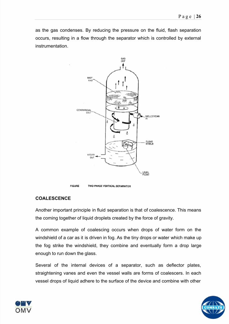
8102019 Gas sweetening Plant
httpslidepdfcomreaderfullgas-sweetening-plant 3062
P a g e | 26
as the gas condenses By reducing the pressure on the fluid flash separation
occurs resulting in a flow through the separator which is controlled by external
instrumentation
COALESCENCE
Another important principle in fluid separation is that of coalescence This means
the coming together of liquid droplets created by the force of gravity
A common example of coalescing occurs when drops of water form on the
windshield of a car as it is driven in fog As the tiny drops or water which make up
the fog strike the windshield they combine and eventually form a drop large
enough to run down the glass
Several of the internal devices of a separator such as deflector plates
straightening vanes and even the vessel walls are forms of coalescers In each
vessel drops of liquid adhere to the surface of the device and combine with other
8102019 Gas sweetening Plant
httpslidepdfcomreaderfullgas-sweetening-plant 3162
P a g e | 27
drops until the drop is large enough to fall out The effectiveness of separation
will also depend upon the total amount of coalescing surface area that is present
There are many different types of separators used in the Oil amp Gas industry
Consequently separators are manufactured with one two or several internal
fittings depending on their use and quick removal of these fluids from the vessel
DEFLECTOR PLATES
These are fitted in front of the inlet to the separator and can be net or
dish-shaped Their purpose is to absorb the impact of the incoming fluids and to
encourage the separation of gas and liquids They also slow the flow rate of the
liquids through the vessel
WEIRS
A weir is a metal wall which is fitted across the inside of the vessel normally to a
height of 50 of the overall height of the separator Its purpose is to assist the
process of three phase separation The inlet fluids (oil plus water) are given time
to separate in the liquid accumulation section The water level (interface) is
normally controlled at 50 of the height of the weir Oil floating on the wateroverflows the weir and accumulates in the small oil compartment where it is
drawn off under level control
CENTRIFUGAL DEVICES
These are used in both vertical and horizontal separators for gas-liquid
separation The device imparts a swirling motion to the fluids entering the vessel
Centrifugal force causes the heavier liquids to travel outwards towards the walls
of the vessel and the lighter gases to flow up the centre Centrifugal devices are
also known as cyclones
VORTEX BREAKERS
When liquid flows through a drain outlet a vortex (whirlpool) will form This can
be seen when we pull the plug from a sink or bath tub The same would happen
as water and oil flow from the separator This condition a vortex could allow gas
to flow down the centre of the whirlpool and enter the liquid phase causing
8102019 Gas sweetening Plant
httpslidepdfcomreaderfullgas-sweetening-plant 3262
P a g e | 28
pressurizing of tanks etc To stop this happening vortex breakers are fitted to all
liquid outlets Although they come in a number of different designs vortex
breakers all serve the same purpose - to prevent a whirlpool from forming
MIST OR DEMISTER PADS
The gas which is released from the fluids in the separator still contains droplets of
oil and water which coalesce and fall when the drops get large enough The
demister pad assists in this process Made from knitted wire and contained within
a sturdy frame it causes the gas to continually change its direction of flow
Because gas changes direction far easier than liquid the gas will flow around
each strand of wire whilst the liquid entrained in the gas stream will continue and
stick to the wire
COALESCING PLATES
There are several different forms of coalescing devices the most common of
which are coalescing plates These plates are mounted in the flow stream of the
fluids and assist in breaking down oil-water emulsions The fluid is forced to
follow a path that constantly changes direction This causes the water droplets to
gather together or coalesce and fall to the bottom of the separator The same
principle is used to separate gas and oil mixtures when the oil droplets are
induced to coalesce Simply stated every surface within the separator including
the separator walls assists with the coalescing process
STRAIGHTENlNG VANES
These are often fitted to horizontal separators to remove turbulence in the gas
stream after initial separation at the inlet deflector
FLOAT SHEILD
Internal floats are used as level controllers Any agitation of the liquid surface or
the effect of coalesced liquids falling on the float may cause control problems
Therefore a float shield is fitted to enclose the float creating an area of still liquid
8102019 Gas sweetening Plant
httpslidepdfcomreaderfullgas-sweetening-plant 3362
P a g e | 29
MEMBRANES
The gas contains 12 carbon dioxide and 22 ppm of hydrogen sulphide at 115oF
and 1100 psig This needs to be removed before the gas can be exported The
majority of carbon dioxide hydrogen sulphide and water is removed by means of
membranes
Membranes are thin semipermeable barriers that selectively separate some
compounds from others Currently the only commercially workable membranes
used for CO2 removal are polymer based for example cellulose acetate
polyimides polyamides polysulfone polycarbonates and polyetherimide The
membrane does not operate as a filter where small molecules are separated
from larger ones through a medium with pores rather it separates based on how
well different compounds dissolve into the membrane and diffuse through it The
membranes are manufactured in flat sheets consisting of an extremely thin
nonporous layer mounted on a much-thicker and highly porous layer of the same
material providing mechanical strength The flat sheets are combined into a
spiral-wound element (Figure below) Feed gas enters along the side of the
membrane and passes through the feed spacers As the gas travels between
membrane sheets CO2 H2S and H2O permeate through the membrane and are
collected in the permeate tube The driving force for transport is the high-feed
pressure and low-permeate pressures The gas on the feed side that does not
permeate leaves through the side of the element opposite the feed position Once
the membranes have been manufactured into elements six to 12 elements are
joined together and inserted into a tube Multiple tubes are mounted on skids in a
horizontal orientation
8102019 Gas sweetening Plant
httpslidepdfcomreaderfullgas-sweetening-plant 3462
P a g e | 30
Figure Membrane general Working
In high H2S applications most polymers have been shown to have very little
resistance to H2S plasticization (ldquosofteningrdquo of the membrane) and as a
consequence can only be used at very low H2S partial pressure limits Cellulose
acetate membranes in contrast have been shown to be applicable at extreme
H2S partial pressure conditions It is these membranes that have been utilized in
the testing to determine the limits of membrane performance in high H 2S
applications
The primary membranes used in Kadanwari facility are Cellulose acetate
Cellulose acetic acid and acetic anhydride are mixed together and reacted to
form cellulose acetate polymers This process is aided by the addition of a small
amount of sulfuric acid which is subsequently neutralized during processing
However the membranes are bought from UOP (vendor) and installed for use
8102019 Gas sweetening Plant
httpslidepdfcomreaderfullgas-sweetening-plant 3562
P a g e | 31
How membrane work
The basic principle of separation is selectivity of certain components of a mixture
for the membrane For example the cellulose acetate membrane has very high
selectivity for CO2 and H2S as compared to CH4 Therefore such type of
membrane can be used in gas sweetening process
The selectivity is directly related to the Permeability of gas which accounts that
which gas can pass across the membrane more easily In simple words
membranes being polymer materials are made of long chains of molecules The
different structure of polymer materials only allow selective molecules to pass
through them depending upon chemical and physical compatibility Thus
permeability depends upon choice of polymer
The permeability is determined by permeability coefficient (P) and is product of
solubility (S) and diffusivity (D)
P = S D
Solubility
The solubility is mainly determined by ease of condensation Heavy molecules
are more readily condensed Therefore higher molecular weighted molecules will
more easily condensed and therefore have greater solubility
Molecule Molecular weight
CH4 16
H2S 34
CO2 44
8102019 Gas sweetening Plant
httpslidepdfcomreaderfullgas-sweetening-plant 3662
P a g e | 32
Diffusivity
Diffusivity is ease of molecule to penetrate into some material It depends on size
of gas molecule Here size of molecule is not to be confused by molecular weight
it is the size of the structure Eg the size of O2 molecule is smaller than N2
Molecule Molecular Diameter (Ao)
CO2 33
H2S 36
Ch4 40
For cellulose acetate
DCO2DCH4 S CO2S CH4 P CO2P CH4
45 73 308
Chemical degradation
Cellulose acetate polymer is chemically degraded by a process called hydrolysis
which means breaking apart by the addition of water This is a chemical reaction
in which water is added to the cellulose acetate polymer causing the release of
acetic acid molecules This process proceeds stepwise until all the acetate
groups are released resulting in the reformation of cellulose Moreover alcohols
aromatic hydrocarbons or solvents with chlorine nitro benzene or similar
aromatic solvents will harm the membrane It will expand and lose plastification in
contact with them
Effect of Temperature
The permeation rates of all gases increases with increasing temperature
however membrane selectivity for CO2 over hydrocarbon decreases at higher
8102019 Gas sweetening Plant
httpslidepdfcomreaderfullgas-sweetening-plant 3762
P a g e | 33
temperature Consequently CO2 removal will improve as operating temperature
increases but hydro carbon recovery will decrease
Primary Membrane
The primary membranes comprise of two trains Each train consists of two
sections AB and CD each section consists of a 30 tube membrane skid (A and
C) followed by a 25 tube skid (B and D) The conditioned gas (after pre-
treatment) enters the primary membrane via the particulate filter adjacent to the
skid The gas is fed to the membranes through a common inlet manifold which
supplies primary membranes skids A and C A pressure control loop located
upstream of the manual inlet isolation valve is provided to maintain a constant
supply pressure to the membrane skid and to allow for preheating at the inlet
prior to skid start-up This pressure control loop can also be used during start-up
to control the pressurization of the pretreatment skid and associated pipes to the
primary membranes
The gas passes through membrane skid A the residual gas exiting the membrane
skid is sent to skid B and the permeate to common permeate discharge header An
identical arrangement is provide on the inlet to skid C as provided on skid A Theresidual gas from skid B combines with the residual gas from skid D in a common
discharge header and is then sent to the H2S polishing towers via the feed coolers
on the pre-treatment skid The permeate from skid B is sent to the common
permeate discharge header The permeate discharge header sends the gas to
either the recycle compressor or the vent header via a pressure control loop
Overpressure protection for the membranes is provided by a pressure safety valve
on the supply header to the membrane banks
8102019 Gas sweetening Plant
httpslidepdfcomreaderfullgas-sweetening-plant 3862
P a g e | 34
Secondary (Recycle) Membrane
The recycle membranes comprise of a single train with two skids each with four
banks of membrane tubes The conditioned gas from the discharge of the recycle
pre-treatment skid is routed to the first recycle membrane skid The gas passes
through the membranes the residual gas is fed to primary membrane (skid A) inlet
via feed gas cooler and permeate to the common permeate discharge header An
identical arrangement is provide on the inlet to skid B Permeate from the recycle
membrane skids A and B is routed to the vent header Some portion of permeate is
heated and sent for regeneration in Mem-Guard units Nitrogen purge can be
connected downstream of the inlet isolation valve on each skid to enable the
membrane tubes to be purged and left pressurized during prolonged shutdown
8102019 Gas sweetening Plant
httpslidepdfcomreaderfullgas-sweetening-plant 3962
P a g e | 35
Figure Flow Diagram of Recycle membrane unit
8102019 Gas sweetening Plant
httpslidepdfcomreaderfullgas-sweetening-plant 4062
P a g e | 36
ADVANTAGES OF MEMBRANE SYSTEMS
Membrane systems have major advantages over more-traditional methods of
acid gas removal
Lower capital cost Membrane systems are skid mounted and so the
scope cost and time taken for site preparation are minimal Installation
costs are significantly lower than alternative technologies especially for
remote areas Furthermore no additional facilities for solvent storage and
water treatment needed by other processes are required
Lower operating costs The only major operating cost for single-stage
membrane systems is membrane replacement This cost is significantly
lower than the solvent replacement and energy costs associated with
traditional technologies The improvements in membrane and
pretreatment design allow a longer useful membrane life which further
reduces operating costs The energy costs of multistage systems with
large recycle compressors are usually comparable to those for traditionaltechnologies
Deferred capital investment Often contracted sales-gas flow rates
increase over time as more wells are brought on-line With traditional
technologies the system design needs to take this later production into
account immediately and so the majority of the equipment is installed
before it is even needed The modular nature of membrane systems
means that only the membranes that are needed at start-up need be
installed The rest can be added either into existing tubes or in new skids
only when they are required
Operational simplicity and high reliability Because single-stage
membrane systems have no moving parts they have almost no
8102019 Gas sweetening Plant
httpslidepdfcomreaderfullgas-sweetening-plant 4162
P a g e | 37
unscheduled downtime and are extremely simple to operate They can
operate unattended for long periods of time The addition of a recycle
compressor adds some complexity to the system but still much less than
with a solvent- or adsorbent-based technology Multistage systems can be
operated at full capacity as single-stage systems when the recycle
compressor is down
Good weight and space efficiency Skid construction can be optimized
to the space available This space efficiency is especially important for
offshore environments where deck area is at a premium and is the
reason why so many new offshore developments have chosen to use
membranes for acid gas removal Figure 6 illustrates the space efficiency
of membrane systems The membrane unit in the lower left corner
replaced all the amine and glycol plant equipment shown in the rest of the
picture
Adaptability Because membrane area is dictated by the percentage of
acid gas removal rather than absolute acid gas removal small variations
in feed acid gas content hardly change the sales-gas acid gas
specification For example a system designed for 10 down to 3 acid
gas removal produces a 35 product from a 12 feed gas and a 5
product from a 15 feed gas
Design efficiency The membrane and pretreatment systems integrate a
number of operations such as dehydration CO2 and H2S removal dew-
point control and mercury removal Traditional acid gas removal
technologies require all of these operations as separate processes and
may also require additional dehydration because some technologies
saturate the product stream with water
8102019 Gas sweetening Plant
httpslidepdfcomreaderfullgas-sweetening-plant 4262
P a g e | 38
Power generation The permeate gas from membrane systems can be
used to provide fuel gas for power generation either for a recycle
compressor or other equipment
Ideal for debottlenecking Because expanding solvent- or adsorbent-
based acid gas removal plants without adding additional trains is difficult
an ideal solution is to use membranes for bulk acid gas removal and leave
the existing plant for final cleanup An additional advantage is that the
permeate gas from the membrane system can often be used as fuel for
the existing plant thus avoiding significant increase in hydrocarbon
losses
Environmentally friendly Membrane systems do not involve the
periodic removal and handling of spent solvents or adsorbents Permeate
gases can be flared used as fuel or re-injected into the well Items thatdo need disposal such as spent membrane elements can be incinerated
Ideal for remote locations Many of the factors mentioned above make
membrane systems a highly desirable technology for remote locations
where spare parts are rare and labor unskilled Furthermore solvents
storage and trucking water supply power generation or extensive
infrastructure are not required
Re-injection optimizations Since the permeate stream from the
membrane system can be operated at elevated pressures it is possible to
further pressurize by re-injection compression train
8102019 Gas sweetening Plant
httpslidepdfcomreaderfullgas-sweetening-plant 4362
P a g e | 39
Sorption
Sorption is a physical and chemical process by which one substance becomes
attached to another
It is of two main types
1 Absorption
2 Adsorption
Absorption
Absorption is a physical or chemical phenomenon or process in which atoms
molecules or ions enter some bulk phase ndash gas liquid or solid material This is a
different process from adsorption since molecules undergoing absorption are
taken up by the volume not by the surface (as in the case for adsorption)
Absorption process may be chemical (reactive) or physical (non-reactive)
Physical absorption
Physical absorption or non-reactive absorption is made between two phases ofmatter a liquid absorbs a gas or a solid absorbs a liquid
When a liquid solvent absorbs a gas mixture or part of it a mass of gas moves
into the liquid For example water may absorb oxygen from the air This mass
transfer takes place at the interface between the liquid and the gas at a rate
depending on both the gas and the liquid This type of absorption depends on the
solubility of gases the pressure and the temperature The rate and amount of
absorption also depend on the surface area of the interface and its duration in
time
When a solid absorbs a liquid mixture or part of it a mass of liquid moves into the
solid For example a clay pot used to store water may absorb some of the water
This mass transfer takes place at the interface between the solid and the liquid
at a rate depending on both the solid and the liquid
8102019 Gas sweetening Plant
httpslidepdfcomreaderfullgas-sweetening-plant 4462
P a g e | 40
Chemical absorption
Chemical absorption or reactive absorption is a chemical reaction between the
absorbed and the absorbing substances Sometimes it combines with physical
absorption This type of absorption depends upon the stoichiometry of the
reaction and the concentration of its reactants
Adsorption
Adsorption is the adhesion of atoms ions or molecules from a gas liquid or
dissolved solid to a surface This process creates a film of the adsorbate on the
surface of the adsorbent The binding to the surface is usually weak and
reversible Compounds with color and those that have taste or odor tend to bind
strongly Compounds that vibrate at frequencies in the visible spectrum are very
often are strongly adsorbed on activated carbon
The most common industrial adsorbents are activated carbon silica gel and
alumina because they present enormous surface areas per unit weight
Depending on the nature of attractive forces existing between the adsorbate and
adsorbent adsorption can be classified as
i) Physical adsorption
ii) Chemical adsorption
i) Physical adsorption (Physisorption)
In physical adsorption the forces of attraction between the molecules of the
adsorbate and the adsorbent are of the weak van der Waals type Since the
forces of attraction are weak the process of physisorption can be easily reversed
by heating or decreasing the pressure of the adsorbate (as in the case of gases)
8102019 Gas sweetening Plant
httpslidepdfcomreaderfullgas-sweetening-plant 4562
P a g e | 41
ii) Chemical adsorption (Chemisorption)
In chemisorption the forces of attraction between the adsorbate and the
adsorbent are very strong the molecules of adsorbate form chemical bonds with
the molecules of the adsorbent present in the surface
Adsorption is generally accompanied by release of energy that is most
adsorption processes are exothermic in nature Adsorption is a spontaneous
process therefore its free energy change is negative (∆Glt0) However the
entropy change associated with adsorption is generally negative because the
adsorbate molecules lose their translation freedom when they get attached to the
surface of the adsorbent Therefore in order for ∆G to be negative the enthalpy
change (∆H) must be sufficiently negative such that (∆G=∆H-T∆S) lt 0 This
explanation accounts for exothermic adsorption processes In cases where
endothermic adsorption occurs the entropy change ∆S is sufficiently positive
such that ∆G remains negative
Pre treatment
The main function of pretreatment skid is to provide membrane inlet specification
gas as mentioned by the vendor UOP It removes the contaminants that would
poison the membranes like dust solids (adsorbent particles) lube oil heavy
hydrocarbons etc It consists of
Feed Cooler
Feed Gas Scrubber
Filter Coalescer
Feed Gas Heater
Activated Carbon Guard Filter
Particle Filter
8102019 Gas sweetening Plant
httpslidepdfcomreaderfullgas-sweetening-plant 4662
8102019 Gas sweetening Plant
httpslidepdfcomreaderfullgas-sweetening-plant 4762
P a g e | 43
The regeneration is carried out by heated permeate gas from the recycle
membranes at 450oF The vessel is depressurized to 20 psi and heated gas is
introduced from top The gas carries out the adsorbed contaminants and leaves
the vessel from bottom cleaning the adsorbent This contaminated gas is burnt in
the flare
UOP the vendor of Memguard unit has never disclosed that what substance
MG3 and MG5 exactly are But as mentioned by vendor that both care class of
aluminosilicates Therefore MG3 can be potassium aluminosilicate and MG5 can
be Calcium aluminosilicate These are molecular sieves adsorbents Molecular
sieves are a microporous material which can selectively adsorb gases andliquids They are synthetic zeolites (crystalline metal aluminosilicates) which
upon dehydration can efficiently and selectively remove water or other
solvents The selectivity of a molecular sieve is determined by its pore size
molecules with a critical diameter which is less than the pore size will be
efficiently adsorbed while larger molecules will be excluded
8102019 Gas sweetening Plant
httpslidepdfcomreaderfullgas-sweetening-plant 4862
P a g e | 44
3A Molecular Sieve Adsorbent
The 3A molecular sieve adsorbent has a 3 angstrom (3A) pore size which means
that any molecule that is larger than the 3 angstrom pores will not be adsorbed
The 3A molecular sieve is the potassium type of A crystalline structure and is a
form of alkali Aluminosilicate For a 3A molecular sieve the sequence rate that
adsorption occurs is He Ne N and H2O
Due to the crystalline structure molecular sieves that have a 3 angstrom pore
size have a very high rate of adsorption and properties that promote a longer life
for products treated by the sieve The most common use for the 3A molecular
sieve is to remove water and moisture from materials that are in gas and liquid
form
5A Molecular Sieve Adsorbent
These are molecular sieve adsorbents with a pore size of 5 angstrom (5A) 5A
molecular sieves are unable to adsorb any molecules or impurities that are
smaller than 5A It is calcium form of type A crystalline structure and is form of analkali-aluminosilicate that is most commonly used to separate isomerous alkanes
from normal alkanes and to co-adsorb moisture and water along with carbon
dioxide from gases In additional 5A molecular sieves are used for gaseous
pressure swing adsorption (PSA)mdashthat is to separate particular gases from other
gases
Adsorption of nC4H10
Adsorption of nC4H10
Adsorption of C3H8 to C22H46
Adsorption of Freon-12 (dichlorodifluoromethane)
Natural gas drying
Normal- and iso-paraffin separation
Separation of aromatic
8102019 Gas sweetening Plant
httpslidepdfcomreaderfullgas-sweetening-plant 4962
P a g e | 45
Inlet Composition of Memguard vessel
COMPSOSITION MOLE
CARBON DIOXIDE 1096
MEHTANE 8593
ETHANE 173
PROPANE 023
I-BUTANE 008
N BUTANE 004
PENTANES 004
HEXANE + 000
NITROGEN 076
WATER 007
Outlet Composition of Memguard vessel
COMPSOSITION MOLE
CARBON DIOXIDE 1098
MEHTANE 8608
ETHANE 173
PROPANE 023
I-BUTANE 008N BUTANE 004
PENTANES 004
HEXANE + 000
NITROGENT 076
WATER 000
H2S polisher
The H2S polishing unit has been designed to treat 187 MMscfday of natural gas
containing up to 11 CO2 and 21 ppm H2S where the level of the CO2 and H2S
is reduced using a MemGuard Membrane separation unit The unit is situated
down-stream of the membrane unit and will further reduce the level of H2S in the
processed gas to a sales gas specification of 38 ppm
8102019 Gas sweetening Plant
httpslidepdfcomreaderfullgas-sweetening-plant 5062
P a g e | 46
This process uses three non-regenerable fixed bed absorber vessels using a low
temperature high activity absorbent The absorbent is a mixture of activated
metal oxides (mainly zinc oxide) The three towers can are generally operated in
parallel arrangement but on demand can be used in series (any of alternate
arrangements of A B C vessels) as shown in figure
The higher sales gas flow rate increased the catalyst consumption and
replacement frequency
ZnO + H2S =gt ZnS + H20
Routine samples are taken from the beds to provide a check on each bed
performance and to follow the saturation profile during the absorbent life After
the adsorbent has been fully utilized the adsorption vessels are recharged with
new adsorbent discarding the utilized one in a safe manner
109oF
1215 psig
Before H2S Polishing After H2S Polishing
8102019 Gas sweetening Plant
httpslidepdfcomreaderfullgas-sweetening-plant 5162
P a g e | 47
Figure
H2S Tower
Inlet pipe
4 Drums of 19mm
ceramic Balls
6 Micron mesh
5 Drums of 50mmceramic
1 Drums of19mm ceramic
01 Drums of6mm ceramic
112 drums of
Catalist ZnO
8102019 Gas sweetening Plant
httpslidepdfcomreaderfullgas-sweetening-plant 5262
P a g e | 48
Recycle Compressor
The permeate gas of the primary membrane unit carries recoverable amount of
CH4 It is fed to recycle membrane unit for further CH 4 recovery But the
permeate pressure from primary membranes which has been reduced to 12 psi
must be regenerated to 1200 psi for the gas to be fed again to the system For
this purpose we have employed recycle compressor The compressor is a four
stage centrifugal compressor It is driven by gas turbine of 31200 HP It has 25
MW producing capacity
Figure Recycle Compressor Process Flow Diagram
8102019 Gas sweetening Plant
httpslidepdfcomreaderfullgas-sweetening-plant 5362
P a g e | 49
Sales Gas Compressor
Gas from H2S polishing unit is sent to sales gas compressor where its pressure
is enhanced to 1100 psi so it may be injected to SNGPL high pressure trunk line
Sales gas compressor is single stage gas turbine driven
Figure Process Flow of Sales Gas Compressor
8102019 Gas sweetening Plant
httpslidepdfcomreaderfullgas-sweetening-plant 5462
P a g e | 50
Cooling Towers
A cooling tower is a heat rejection device which extracts waste heat to theatmosphere through the cooling of a water stream to a lower temperature Hot
water from the system enters the cooling tower and is distributed over the fill
(heat transfer surface) Air is induced or forced through the fill causing a small
portion of the water to evaporate This evaporation removes heat from the
remaining water which is collected in the cold water basin and returned to the
system to absorb more heat Each cooling tower line although operating under
the same basic principle of operation is arranged a little differently
Types
Natural draft mdash Utilizes buoyancy via a tall chimney Warm moist air naturally
rises due to the density differential compared to the dry cooler outside air Warm
moist air is less dense than drier air at the same pressure This moist air
buoyancy produces an upwards current of air through the tower
Mechanical draft mdash Uses power-driven fan motors to force or draw airthrough the tower
o Induced draft mdash A mechanical draft tower with a fan at the
discharge (at the top) which pulls air up through the tower The fan
induces hot moist air out the discharge This produces low entering
and high exiting air velocities reducing the possibility of
recirculation in which discharged air flows back into the air intake
o Forced draft mdash A mechanical draft tower with a blower type fan at
the intake The fan forces air into the tower creating high entering
and low exiting air velocities The low exiting velocity is much more
susceptible to recirculation This fanfill geometry is also known as
blow-through
8102019 Gas sweetening Plant
httpslidepdfcomreaderfullgas-sweetening-plant 5562
P a g e | 51
Forced Draft Cooling Tower Vs Induced Draft Cooling Tower
Induced Draft Cooling Tower have the ability to handle large water flow
rate than Forced Draft Cooling Tower
Induced Draft Cooling Tower is suitable for large cell sizes and fan sizes
as compared with Forced Draft Larger fan size may result in greater
efficiency and consequently lower power and sound level
Forced Draft Cooling Tower can be square or rectangular type only
however Induced Draft Cooling Towers can be round square or
rectangular type
Induced Draft Cooling Tower uses more compact ground area than Forced
Draft Cooling Tower equivalent capacity due to absence of fan on one
side
Fan equipment is warm exhaust air is less liable to icing up in winter
operation (Cold Countries)
Higher velocity in Forced Draft Cooling Tower cause drop in suspension
and cause additional static resistance to system
Configuration
There are two main configurations of factory assembled cooling towers crossflow
and counterflow In crossflow cooling towers the water flows vertically down the
fill as air flows horizontally across In counterflow cooling towers the water flows
vertically down the fill as air flows vertically up
Crossflow Configuration Counterflow Configuration
8102019 Gas sweetening Plant
httpslidepdfcomreaderfullgas-sweetening-plant 5662
P a g e | 52
Drift mdash Water droplets that are carried out of the cooling tower with the exhaust
air Drift droplets have the same concentration of impurities as the water entering
the tower The drift rate is typically reduced by employing baffle-like devices
called drift eliminators through which the air must travel after leaving the fill and
spray zones of the tower
Blow-out mdash Water droplets blown out of the cooling tower by wind generally at
the air inlet openings Water may also be lost in the absence of wind through
splashing or misting Devices such as wind screens louvers splash deflectors
and water diverters are used to limit these losses
Blow-down mdash The portion of the circulating water flow that is removed (usually
discharged to a drain) in order to maintain the amount of Total Dissolved Solids
(TDS) and other impurities at an acceptably low level Higher TDS concentration
in solution may result from greater cooling tower efficiency However the higher
the TDS concentration the greater the risk of scale biological growth and
corrosion
Make-up mdash The water that must be added to the circulating water system in
order to compensate for water losses such as evaporation drift loss blow-out
blow-down etc
Approach mdash The approach is the difference in temperature between the cooled-
water temperature and the entering-air wet bulb temperature
Range mdash The range is the temperature difference between the warm water inlet
and cooled water exit
Fill mdash Inside the tower fills are added to increase contact surface as well as
contact time between air and water to provide better heat transfer The efficiency
of the tower depends on the selection and amount of fill
8102019 Gas sweetening Plant
httpslidepdfcomreaderfullgas-sweetening-plant 5762
P a g e | 53
There are two types of fills that may be used
o Film type fill (causes water to spread into a thin film)
o Splash type fill (breaks up falling stream of water and interrupts its
vertical progress)
Important
Scale build up is controlled by adding chemicals to the cooling loop and diluting
the concentration by blow down and make-up Following chemicals are added to
the Cooling to control CorrosionSale and microbial growth
Corrosion Inhibitor To control corrosion in the Cooling system
Dispersant To kept ions in suspension to avoid settle down and buildup
Sodium hypo Chlorite To Control microbial Growth
Acid To control Alkalinity in the system
High Stress Polymer To run the system at higher conductivity It is a
multifunctional polymer for Zinc amp Phosphate stabilization in cooling tower
Fin Fan Cooler
Fin fan heat exchanger is simply a pressure vessel which cools a circulating fluid
within finned tubes by forcing ambient air over the exterior of the tubes A
common example of an air cooler is a carrsquos radiator Fin Fan Coolers are used in
any application where large quantities of heat need to be transferred This
includes chemical and petrochemical industries power stations waste-to-energy
facilities as well as steelworks
Fin Fan Cooler are used for two primary reasons
They increase plant efficiency
They are a green solution as compared to cooling towers and shell and
tube heat exchangers because they do not require an auxiliary water
8102019 Gas sweetening Plant
httpslidepdfcomreaderfullgas-sweetening-plant 5862
P a g e | 54
supply (water lost due to drift and evaporation plus no water treatment
chemicals are required)
Figure General Overview of Fin Fan Cooler
Produced Water
The produced water system receives liquid from the equipment Miano slug
catcher train 1 and 2 inlet separators and is fed to three phase separator where
water oil and gas is separated The gases produced are burnt in incinerator
whereas hydrocarbon liquid is stored to be sold Liquid from compressors
recycle inlet separator recycle feed scrubber high and low pressure slug
catchers is passed to degasser Separated water is injected down the earth
Incinerator
The term incinerate means to burn something until nothing is left but ashes An
incinerator is a unit or facility used to burn trash and other types of waste until it is
reduced to ash An incinerator is constructed of heavy well-insulated materials
so that it does not give off extreme amounts of external heat The high levels of
heat are kept inside the furnace or unit so that the waste is burned quickly and
efficiently If the heat were allowed to escape the waste would not burn as
completely or as rapidly
8102019 Gas sweetening Plant
httpslidepdfcomreaderfullgas-sweetening-plant 5962
P a g e | 55
Control System
The plant is controlled at CCR (Central Control Room) by PLCs (Programmable
Logic Controllers) through fiber optic control line All control parameters are
received at LER (Local Equipment Room) via two optic fiber control lines One
being primary and other secondary operating in redundancy ie if primary fails
control shifts to secondary These control parameters are sent to CCR via single
optic fiber cable
Safety System
Wellheads and Gas Processing Plant have their own Fire amp Gas detection
systems emergency shutdown (ESD) Plant has a fault tolerant controller It is
based on Triple Modular Redundant (TMR) architecture manufactured by
Triconex The TMR system is based on three isolated parallel control systems
integrated into one system The system operates on a two out of three voting
principle which provides high integrity error free uninterrupted operation with no
single point of failure The TMR receives inputs from Process Sensors Manual
Switches Fire amp Gas Detectors Packaged Equipment Control Systems and
Product Exporting Facilities The TMR carries out cause and effect processing on
the data received and where necessary produces output signals Outputs from
the TMR are hard wired directly to ESD shutdown and blow down valve
solenoids motor control instrumentelectrical interfaces to control electrical
drives package equipment logic control systems manifold area as well as
telecoms
The operator in central control room is able to accept alarms and once the fault
has been cleared reset the input All the control systems are centralized to a
single interface All the PLCs (Programmable Logic Controllers) communicate with
the servers and servers communicate with the clients through Ethernet connectivity
Centralization eases the navigation of different systems at a common interface
Emergency Shutdown
The ESD system receives inputs from field mounted instrumentation on the process
8102019 Gas sweetening Plant
httpslidepdfcomreaderfullgas-sweetening-plant 6062
P a g e | 56
and utility equipment and initiates executive actions appropriate to the level of ESD
The system is an Active system which is in standby and will activate when in an
alarm or fault condition The Kadanwari Gas Process Facility ESD system is
comprised of five (5) levels The emergency severity decreases with increasing ESD
level number
ESD 1
This shutdown level is automatically initiated by fire major gas leak or a detected
toxic atmosphere in the process area of the plant or manually from CCR A level 1
shutdown will cause all production to cease close all emergency shutdown
valves stop the process and shutdown of the main power generation The
emergency vent valves to the stack will open and in addition all equipment of zone 1
certified will be isolated This is the highest level of ESD and will cause the following
to occur
All Shutdown Valves (SDVs) on the process facility will close All slowdown Valves (BDVs) on the process facility will open
All Main Gas Driven Generators will be tripped
Emergency Diesel Generator will start
All electrical power to process and utility rotating equipment will be
isolated
Wellhead Choke Valves Close Wing Valves Close Upper Master Valve
(UMV) Close
ESD 2
This shutdown level is activated automatically if a major process or utility failure
occurs or manually from CCR All production to the plant from the wellhead is
stopped All emergency shutdown valves trip to their fail safe position
Venting shall be as specified This level of ESD will cause the following to occur
8102019 Gas sweetening Plant
httpslidepdfcomreaderfullgas-sweetening-plant 6162
P a g e | 57
All Shutdown Valves (SDVs) on the process facility will close
All electrical power to process and utility rotating equipment will be
isolated
Wellhead Choke Valve Close Wing Valves Close and Upper Master Valve(UMV) Close
ESD 3
The level 3 shutdown isolates and stops a single process train only Production
continues via the other train This ESD level is initiated by process conditions or
operator at local panel This level of ESD will cause the following to occur
ESD 3A Train 1 production to cease
ESD 3B Train 2 production to cease
All online wellhead choke valves go to minimum flow ie (1O )
ESD 4
A level 4 shutdown shall cease all production from an entire field either
Kadanwari or Miano upstream of the associated slug catchers ESD 4K for
Kadanwari amp ESD 4M for Miano This ESD level is initiated automatically by slug
catcher abnormal process conditions This level of ESD will cause the following
to occur
All SDVs close isolating the relevant slug catcher and its upstream gas
production facility from the Kadanwari Gas Processing Plant
All Wellhead Choke Valves Close Wing Valves Close and Upper MasterValves (UMV) of the relevant gas production facility Close
A parallel timer is provided to close within 10 second if not closed in given
time SSSV seals the well
ESD 5
A level 5 shutdown represents equipment shutdown for the protection of the
individual equipment without any change in the process This level of ESD is for the
protection of various pieces of equipment and is initiated by its own inputs eg
8102019 Gas sweetening Plant
httpslidepdfcomreaderfullgas-sweetening-plant 6262
8102019 Gas sweetening Plant
httpslidepdfcomreaderfullgas-sweetening-plant 3362
P a g e | 29
MEMBRANES
The gas contains 12 carbon dioxide and 22 ppm of hydrogen sulphide at 115oF
and 1100 psig This needs to be removed before the gas can be exported The
majority of carbon dioxide hydrogen sulphide and water is removed by means of
membranes
Membranes are thin semipermeable barriers that selectively separate some
compounds from others Currently the only commercially workable membranes
used for CO2 removal are polymer based for example cellulose acetate
polyimides polyamides polysulfone polycarbonates and polyetherimide The
membrane does not operate as a filter where small molecules are separated
from larger ones through a medium with pores rather it separates based on how
well different compounds dissolve into the membrane and diffuse through it The
membranes are manufactured in flat sheets consisting of an extremely thin
nonporous layer mounted on a much-thicker and highly porous layer of the same
material providing mechanical strength The flat sheets are combined into a
spiral-wound element (Figure below) Feed gas enters along the side of the
membrane and passes through the feed spacers As the gas travels between
membrane sheets CO2 H2S and H2O permeate through the membrane and are
collected in the permeate tube The driving force for transport is the high-feed
pressure and low-permeate pressures The gas on the feed side that does not
permeate leaves through the side of the element opposite the feed position Once
the membranes have been manufactured into elements six to 12 elements are
joined together and inserted into a tube Multiple tubes are mounted on skids in a
horizontal orientation
8102019 Gas sweetening Plant
httpslidepdfcomreaderfullgas-sweetening-plant 3462
P a g e | 30
Figure Membrane general Working
In high H2S applications most polymers have been shown to have very little
resistance to H2S plasticization (ldquosofteningrdquo of the membrane) and as a
consequence can only be used at very low H2S partial pressure limits Cellulose
acetate membranes in contrast have been shown to be applicable at extreme
H2S partial pressure conditions It is these membranes that have been utilized in
the testing to determine the limits of membrane performance in high H 2S
applications
The primary membranes used in Kadanwari facility are Cellulose acetate
Cellulose acetic acid and acetic anhydride are mixed together and reacted to
form cellulose acetate polymers This process is aided by the addition of a small
amount of sulfuric acid which is subsequently neutralized during processing
However the membranes are bought from UOP (vendor) and installed for use
8102019 Gas sweetening Plant
httpslidepdfcomreaderfullgas-sweetening-plant 3562
P a g e | 31
How membrane work
The basic principle of separation is selectivity of certain components of a mixture
for the membrane For example the cellulose acetate membrane has very high
selectivity for CO2 and H2S as compared to CH4 Therefore such type of
membrane can be used in gas sweetening process
The selectivity is directly related to the Permeability of gas which accounts that
which gas can pass across the membrane more easily In simple words
membranes being polymer materials are made of long chains of molecules The
different structure of polymer materials only allow selective molecules to pass
through them depending upon chemical and physical compatibility Thus
permeability depends upon choice of polymer
The permeability is determined by permeability coefficient (P) and is product of
solubility (S) and diffusivity (D)
P = S D
Solubility
The solubility is mainly determined by ease of condensation Heavy molecules
are more readily condensed Therefore higher molecular weighted molecules will
more easily condensed and therefore have greater solubility
Molecule Molecular weight
CH4 16
H2S 34
CO2 44
8102019 Gas sweetening Plant
httpslidepdfcomreaderfullgas-sweetening-plant 3662
P a g e | 32
Diffusivity
Diffusivity is ease of molecule to penetrate into some material It depends on size
of gas molecule Here size of molecule is not to be confused by molecular weight
it is the size of the structure Eg the size of O2 molecule is smaller than N2
Molecule Molecular Diameter (Ao)
CO2 33
H2S 36
Ch4 40
For cellulose acetate
DCO2DCH4 S CO2S CH4 P CO2P CH4
45 73 308
Chemical degradation
Cellulose acetate polymer is chemically degraded by a process called hydrolysis
which means breaking apart by the addition of water This is a chemical reaction
in which water is added to the cellulose acetate polymer causing the release of
acetic acid molecules This process proceeds stepwise until all the acetate
groups are released resulting in the reformation of cellulose Moreover alcohols
aromatic hydrocarbons or solvents with chlorine nitro benzene or similar
aromatic solvents will harm the membrane It will expand and lose plastification in
contact with them
Effect of Temperature
The permeation rates of all gases increases with increasing temperature
however membrane selectivity for CO2 over hydrocarbon decreases at higher
8102019 Gas sweetening Plant
httpslidepdfcomreaderfullgas-sweetening-plant 3762
P a g e | 33
temperature Consequently CO2 removal will improve as operating temperature
increases but hydro carbon recovery will decrease
Primary Membrane
The primary membranes comprise of two trains Each train consists of two
sections AB and CD each section consists of a 30 tube membrane skid (A and
C) followed by a 25 tube skid (B and D) The conditioned gas (after pre-
treatment) enters the primary membrane via the particulate filter adjacent to the
skid The gas is fed to the membranes through a common inlet manifold which
supplies primary membranes skids A and C A pressure control loop located
upstream of the manual inlet isolation valve is provided to maintain a constant
supply pressure to the membrane skid and to allow for preheating at the inlet
prior to skid start-up This pressure control loop can also be used during start-up
to control the pressurization of the pretreatment skid and associated pipes to the
primary membranes
The gas passes through membrane skid A the residual gas exiting the membrane
skid is sent to skid B and the permeate to common permeate discharge header An
identical arrangement is provide on the inlet to skid C as provided on skid A Theresidual gas from skid B combines with the residual gas from skid D in a common
discharge header and is then sent to the H2S polishing towers via the feed coolers
on the pre-treatment skid The permeate from skid B is sent to the common
permeate discharge header The permeate discharge header sends the gas to
either the recycle compressor or the vent header via a pressure control loop
Overpressure protection for the membranes is provided by a pressure safety valve
on the supply header to the membrane banks
8102019 Gas sweetening Plant
httpslidepdfcomreaderfullgas-sweetening-plant 3862
P a g e | 34
Secondary (Recycle) Membrane
The recycle membranes comprise of a single train with two skids each with four
banks of membrane tubes The conditioned gas from the discharge of the recycle
pre-treatment skid is routed to the first recycle membrane skid The gas passes
through the membranes the residual gas is fed to primary membrane (skid A) inlet
via feed gas cooler and permeate to the common permeate discharge header An
identical arrangement is provide on the inlet to skid B Permeate from the recycle
membrane skids A and B is routed to the vent header Some portion of permeate is
heated and sent for regeneration in Mem-Guard units Nitrogen purge can be
connected downstream of the inlet isolation valve on each skid to enable the
membrane tubes to be purged and left pressurized during prolonged shutdown
8102019 Gas sweetening Plant
httpslidepdfcomreaderfullgas-sweetening-plant 3962
P a g e | 35
Figure Flow Diagram of Recycle membrane unit
8102019 Gas sweetening Plant
httpslidepdfcomreaderfullgas-sweetening-plant 4062
P a g e | 36
ADVANTAGES OF MEMBRANE SYSTEMS
Membrane systems have major advantages over more-traditional methods of
acid gas removal
Lower capital cost Membrane systems are skid mounted and so the
scope cost and time taken for site preparation are minimal Installation
costs are significantly lower than alternative technologies especially for
remote areas Furthermore no additional facilities for solvent storage and
water treatment needed by other processes are required
Lower operating costs The only major operating cost for single-stage
membrane systems is membrane replacement This cost is significantly
lower than the solvent replacement and energy costs associated with
traditional technologies The improvements in membrane and
pretreatment design allow a longer useful membrane life which further
reduces operating costs The energy costs of multistage systems with
large recycle compressors are usually comparable to those for traditionaltechnologies
Deferred capital investment Often contracted sales-gas flow rates
increase over time as more wells are brought on-line With traditional
technologies the system design needs to take this later production into
account immediately and so the majority of the equipment is installed
before it is even needed The modular nature of membrane systems
means that only the membranes that are needed at start-up need be
installed The rest can be added either into existing tubes or in new skids
only when they are required
Operational simplicity and high reliability Because single-stage
membrane systems have no moving parts they have almost no
8102019 Gas sweetening Plant
httpslidepdfcomreaderfullgas-sweetening-plant 4162
P a g e | 37
unscheduled downtime and are extremely simple to operate They can
operate unattended for long periods of time The addition of a recycle
compressor adds some complexity to the system but still much less than
with a solvent- or adsorbent-based technology Multistage systems can be
operated at full capacity as single-stage systems when the recycle
compressor is down
Good weight and space efficiency Skid construction can be optimized
to the space available This space efficiency is especially important for
offshore environments where deck area is at a premium and is the
reason why so many new offshore developments have chosen to use
membranes for acid gas removal Figure 6 illustrates the space efficiency
of membrane systems The membrane unit in the lower left corner
replaced all the amine and glycol plant equipment shown in the rest of the
picture
Adaptability Because membrane area is dictated by the percentage of
acid gas removal rather than absolute acid gas removal small variations
in feed acid gas content hardly change the sales-gas acid gas
specification For example a system designed for 10 down to 3 acid
gas removal produces a 35 product from a 12 feed gas and a 5
product from a 15 feed gas
Design efficiency The membrane and pretreatment systems integrate a
number of operations such as dehydration CO2 and H2S removal dew-
point control and mercury removal Traditional acid gas removal
technologies require all of these operations as separate processes and
may also require additional dehydration because some technologies
saturate the product stream with water
8102019 Gas sweetening Plant
httpslidepdfcomreaderfullgas-sweetening-plant 4262
P a g e | 38
Power generation The permeate gas from membrane systems can be
used to provide fuel gas for power generation either for a recycle
compressor or other equipment
Ideal for debottlenecking Because expanding solvent- or adsorbent-
based acid gas removal plants without adding additional trains is difficult
an ideal solution is to use membranes for bulk acid gas removal and leave
the existing plant for final cleanup An additional advantage is that the
permeate gas from the membrane system can often be used as fuel for
the existing plant thus avoiding significant increase in hydrocarbon
losses
Environmentally friendly Membrane systems do not involve the
periodic removal and handling of spent solvents or adsorbents Permeate
gases can be flared used as fuel or re-injected into the well Items thatdo need disposal such as spent membrane elements can be incinerated
Ideal for remote locations Many of the factors mentioned above make
membrane systems a highly desirable technology for remote locations
where spare parts are rare and labor unskilled Furthermore solvents
storage and trucking water supply power generation or extensive
infrastructure are not required
Re-injection optimizations Since the permeate stream from the
membrane system can be operated at elevated pressures it is possible to
further pressurize by re-injection compression train
8102019 Gas sweetening Plant
httpslidepdfcomreaderfullgas-sweetening-plant 4362
P a g e | 39
Sorption
Sorption is a physical and chemical process by which one substance becomes
attached to another
It is of two main types
1 Absorption
2 Adsorption
Absorption
Absorption is a physical or chemical phenomenon or process in which atoms
molecules or ions enter some bulk phase ndash gas liquid or solid material This is a
different process from adsorption since molecules undergoing absorption are
taken up by the volume not by the surface (as in the case for adsorption)
Absorption process may be chemical (reactive) or physical (non-reactive)
Physical absorption
Physical absorption or non-reactive absorption is made between two phases ofmatter a liquid absorbs a gas or a solid absorbs a liquid
When a liquid solvent absorbs a gas mixture or part of it a mass of gas moves
into the liquid For example water may absorb oxygen from the air This mass
transfer takes place at the interface between the liquid and the gas at a rate
depending on both the gas and the liquid This type of absorption depends on the
solubility of gases the pressure and the temperature The rate and amount of
absorption also depend on the surface area of the interface and its duration in
time
When a solid absorbs a liquid mixture or part of it a mass of liquid moves into the
solid For example a clay pot used to store water may absorb some of the water
This mass transfer takes place at the interface between the solid and the liquid
at a rate depending on both the solid and the liquid
8102019 Gas sweetening Plant
httpslidepdfcomreaderfullgas-sweetening-plant 4462
P a g e | 40
Chemical absorption
Chemical absorption or reactive absorption is a chemical reaction between the
absorbed and the absorbing substances Sometimes it combines with physical
absorption This type of absorption depends upon the stoichiometry of the
reaction and the concentration of its reactants
Adsorption
Adsorption is the adhesion of atoms ions or molecules from a gas liquid or
dissolved solid to a surface This process creates a film of the adsorbate on the
surface of the adsorbent The binding to the surface is usually weak and
reversible Compounds with color and those that have taste or odor tend to bind
strongly Compounds that vibrate at frequencies in the visible spectrum are very
often are strongly adsorbed on activated carbon
The most common industrial adsorbents are activated carbon silica gel and
alumina because they present enormous surface areas per unit weight
Depending on the nature of attractive forces existing between the adsorbate and
adsorbent adsorption can be classified as
i) Physical adsorption
ii) Chemical adsorption
i) Physical adsorption (Physisorption)
In physical adsorption the forces of attraction between the molecules of the
adsorbate and the adsorbent are of the weak van der Waals type Since the
forces of attraction are weak the process of physisorption can be easily reversed
by heating or decreasing the pressure of the adsorbate (as in the case of gases)
8102019 Gas sweetening Plant
httpslidepdfcomreaderfullgas-sweetening-plant 4562
P a g e | 41
ii) Chemical adsorption (Chemisorption)
In chemisorption the forces of attraction between the adsorbate and the
adsorbent are very strong the molecules of adsorbate form chemical bonds with
the molecules of the adsorbent present in the surface
Adsorption is generally accompanied by release of energy that is most
adsorption processes are exothermic in nature Adsorption is a spontaneous
process therefore its free energy change is negative (∆Glt0) However the
entropy change associated with adsorption is generally negative because the
adsorbate molecules lose their translation freedom when they get attached to the
surface of the adsorbent Therefore in order for ∆G to be negative the enthalpy
change (∆H) must be sufficiently negative such that (∆G=∆H-T∆S) lt 0 This
explanation accounts for exothermic adsorption processes In cases where
endothermic adsorption occurs the entropy change ∆S is sufficiently positive
such that ∆G remains negative
Pre treatment
The main function of pretreatment skid is to provide membrane inlet specification
gas as mentioned by the vendor UOP It removes the contaminants that would
poison the membranes like dust solids (adsorbent particles) lube oil heavy
hydrocarbons etc It consists of
Feed Cooler
Feed Gas Scrubber
Filter Coalescer
Feed Gas Heater
Activated Carbon Guard Filter
Particle Filter
8102019 Gas sweetening Plant
httpslidepdfcomreaderfullgas-sweetening-plant 4662
8102019 Gas sweetening Plant
httpslidepdfcomreaderfullgas-sweetening-plant 4762
P a g e | 43
The regeneration is carried out by heated permeate gas from the recycle
membranes at 450oF The vessel is depressurized to 20 psi and heated gas is
introduced from top The gas carries out the adsorbed contaminants and leaves
the vessel from bottom cleaning the adsorbent This contaminated gas is burnt in
the flare
UOP the vendor of Memguard unit has never disclosed that what substance
MG3 and MG5 exactly are But as mentioned by vendor that both care class of
aluminosilicates Therefore MG3 can be potassium aluminosilicate and MG5 can
be Calcium aluminosilicate These are molecular sieves adsorbents Molecular
sieves are a microporous material which can selectively adsorb gases andliquids They are synthetic zeolites (crystalline metal aluminosilicates) which
upon dehydration can efficiently and selectively remove water or other
solvents The selectivity of a molecular sieve is determined by its pore size
molecules with a critical diameter which is less than the pore size will be
efficiently adsorbed while larger molecules will be excluded
8102019 Gas sweetening Plant
httpslidepdfcomreaderfullgas-sweetening-plant 4862
P a g e | 44
3A Molecular Sieve Adsorbent
The 3A molecular sieve adsorbent has a 3 angstrom (3A) pore size which means
that any molecule that is larger than the 3 angstrom pores will not be adsorbed
The 3A molecular sieve is the potassium type of A crystalline structure and is a
form of alkali Aluminosilicate For a 3A molecular sieve the sequence rate that
adsorption occurs is He Ne N and H2O
Due to the crystalline structure molecular sieves that have a 3 angstrom pore
size have a very high rate of adsorption and properties that promote a longer life
for products treated by the sieve The most common use for the 3A molecular
sieve is to remove water and moisture from materials that are in gas and liquid
form
5A Molecular Sieve Adsorbent
These are molecular sieve adsorbents with a pore size of 5 angstrom (5A) 5A
molecular sieves are unable to adsorb any molecules or impurities that are
smaller than 5A It is calcium form of type A crystalline structure and is form of analkali-aluminosilicate that is most commonly used to separate isomerous alkanes
from normal alkanes and to co-adsorb moisture and water along with carbon
dioxide from gases In additional 5A molecular sieves are used for gaseous
pressure swing adsorption (PSA)mdashthat is to separate particular gases from other
gases
Adsorption of nC4H10
Adsorption of nC4H10
Adsorption of C3H8 to C22H46
Adsorption of Freon-12 (dichlorodifluoromethane)
Natural gas drying
Normal- and iso-paraffin separation
Separation of aromatic
8102019 Gas sweetening Plant
httpslidepdfcomreaderfullgas-sweetening-plant 4962
P a g e | 45
Inlet Composition of Memguard vessel
COMPSOSITION MOLE
CARBON DIOXIDE 1096
MEHTANE 8593
ETHANE 173
PROPANE 023
I-BUTANE 008
N BUTANE 004
PENTANES 004
HEXANE + 000
NITROGEN 076
WATER 007
Outlet Composition of Memguard vessel
COMPSOSITION MOLE
CARBON DIOXIDE 1098
MEHTANE 8608
ETHANE 173
PROPANE 023
I-BUTANE 008N BUTANE 004
PENTANES 004
HEXANE + 000
NITROGENT 076
WATER 000
H2S polisher
The H2S polishing unit has been designed to treat 187 MMscfday of natural gas
containing up to 11 CO2 and 21 ppm H2S where the level of the CO2 and H2S
is reduced using a MemGuard Membrane separation unit The unit is situated
down-stream of the membrane unit and will further reduce the level of H2S in the
processed gas to a sales gas specification of 38 ppm
8102019 Gas sweetening Plant
httpslidepdfcomreaderfullgas-sweetening-plant 5062
P a g e | 46
This process uses three non-regenerable fixed bed absorber vessels using a low
temperature high activity absorbent The absorbent is a mixture of activated
metal oxides (mainly zinc oxide) The three towers can are generally operated in
parallel arrangement but on demand can be used in series (any of alternate
arrangements of A B C vessels) as shown in figure
The higher sales gas flow rate increased the catalyst consumption and
replacement frequency
ZnO + H2S =gt ZnS + H20
Routine samples are taken from the beds to provide a check on each bed
performance and to follow the saturation profile during the absorbent life After
the adsorbent has been fully utilized the adsorption vessels are recharged with
new adsorbent discarding the utilized one in a safe manner
109oF
1215 psig
Before H2S Polishing After H2S Polishing
8102019 Gas sweetening Plant
httpslidepdfcomreaderfullgas-sweetening-plant 5162
P a g e | 47
Figure
H2S Tower
Inlet pipe
4 Drums of 19mm
ceramic Balls
6 Micron mesh
5 Drums of 50mmceramic
1 Drums of19mm ceramic
01 Drums of6mm ceramic
112 drums of
Catalist ZnO
8102019 Gas sweetening Plant
httpslidepdfcomreaderfullgas-sweetening-plant 5262
P a g e | 48
Recycle Compressor
The permeate gas of the primary membrane unit carries recoverable amount of
CH4 It is fed to recycle membrane unit for further CH 4 recovery But the
permeate pressure from primary membranes which has been reduced to 12 psi
must be regenerated to 1200 psi for the gas to be fed again to the system For
this purpose we have employed recycle compressor The compressor is a four
stage centrifugal compressor It is driven by gas turbine of 31200 HP It has 25
MW producing capacity
Figure Recycle Compressor Process Flow Diagram
8102019 Gas sweetening Plant
httpslidepdfcomreaderfullgas-sweetening-plant 5362
P a g e | 49
Sales Gas Compressor
Gas from H2S polishing unit is sent to sales gas compressor where its pressure
is enhanced to 1100 psi so it may be injected to SNGPL high pressure trunk line
Sales gas compressor is single stage gas turbine driven
Figure Process Flow of Sales Gas Compressor
8102019 Gas sweetening Plant
httpslidepdfcomreaderfullgas-sweetening-plant 5462
P a g e | 50
Cooling Towers
A cooling tower is a heat rejection device which extracts waste heat to theatmosphere through the cooling of a water stream to a lower temperature Hot
water from the system enters the cooling tower and is distributed over the fill
(heat transfer surface) Air is induced or forced through the fill causing a small
portion of the water to evaporate This evaporation removes heat from the
remaining water which is collected in the cold water basin and returned to the
system to absorb more heat Each cooling tower line although operating under
the same basic principle of operation is arranged a little differently
Types
Natural draft mdash Utilizes buoyancy via a tall chimney Warm moist air naturally
rises due to the density differential compared to the dry cooler outside air Warm
moist air is less dense than drier air at the same pressure This moist air
buoyancy produces an upwards current of air through the tower
Mechanical draft mdash Uses power-driven fan motors to force or draw airthrough the tower
o Induced draft mdash A mechanical draft tower with a fan at the
discharge (at the top) which pulls air up through the tower The fan
induces hot moist air out the discharge This produces low entering
and high exiting air velocities reducing the possibility of
recirculation in which discharged air flows back into the air intake
o Forced draft mdash A mechanical draft tower with a blower type fan at
the intake The fan forces air into the tower creating high entering
and low exiting air velocities The low exiting velocity is much more
susceptible to recirculation This fanfill geometry is also known as
blow-through
8102019 Gas sweetening Plant
httpslidepdfcomreaderfullgas-sweetening-plant 5562
P a g e | 51
Forced Draft Cooling Tower Vs Induced Draft Cooling Tower
Induced Draft Cooling Tower have the ability to handle large water flow
rate than Forced Draft Cooling Tower
Induced Draft Cooling Tower is suitable for large cell sizes and fan sizes
as compared with Forced Draft Larger fan size may result in greater
efficiency and consequently lower power and sound level
Forced Draft Cooling Tower can be square or rectangular type only
however Induced Draft Cooling Towers can be round square or
rectangular type
Induced Draft Cooling Tower uses more compact ground area than Forced
Draft Cooling Tower equivalent capacity due to absence of fan on one
side
Fan equipment is warm exhaust air is less liable to icing up in winter
operation (Cold Countries)
Higher velocity in Forced Draft Cooling Tower cause drop in suspension
and cause additional static resistance to system
Configuration
There are two main configurations of factory assembled cooling towers crossflow
and counterflow In crossflow cooling towers the water flows vertically down the
fill as air flows horizontally across In counterflow cooling towers the water flows
vertically down the fill as air flows vertically up
Crossflow Configuration Counterflow Configuration
8102019 Gas sweetening Plant
httpslidepdfcomreaderfullgas-sweetening-plant 5662
P a g e | 52
Drift mdash Water droplets that are carried out of the cooling tower with the exhaust
air Drift droplets have the same concentration of impurities as the water entering
the tower The drift rate is typically reduced by employing baffle-like devices
called drift eliminators through which the air must travel after leaving the fill and
spray zones of the tower
Blow-out mdash Water droplets blown out of the cooling tower by wind generally at
the air inlet openings Water may also be lost in the absence of wind through
splashing or misting Devices such as wind screens louvers splash deflectors
and water diverters are used to limit these losses
Blow-down mdash The portion of the circulating water flow that is removed (usually
discharged to a drain) in order to maintain the amount of Total Dissolved Solids
(TDS) and other impurities at an acceptably low level Higher TDS concentration
in solution may result from greater cooling tower efficiency However the higher
the TDS concentration the greater the risk of scale biological growth and
corrosion
Make-up mdash The water that must be added to the circulating water system in
order to compensate for water losses such as evaporation drift loss blow-out
blow-down etc
Approach mdash The approach is the difference in temperature between the cooled-
water temperature and the entering-air wet bulb temperature
Range mdash The range is the temperature difference between the warm water inlet
and cooled water exit
Fill mdash Inside the tower fills are added to increase contact surface as well as
contact time between air and water to provide better heat transfer The efficiency
of the tower depends on the selection and amount of fill
8102019 Gas sweetening Plant
httpslidepdfcomreaderfullgas-sweetening-plant 5762
P a g e | 53
There are two types of fills that may be used
o Film type fill (causes water to spread into a thin film)
o Splash type fill (breaks up falling stream of water and interrupts its
vertical progress)
Important
Scale build up is controlled by adding chemicals to the cooling loop and diluting
the concentration by blow down and make-up Following chemicals are added to
the Cooling to control CorrosionSale and microbial growth
Corrosion Inhibitor To control corrosion in the Cooling system
Dispersant To kept ions in suspension to avoid settle down and buildup
Sodium hypo Chlorite To Control microbial Growth
Acid To control Alkalinity in the system
High Stress Polymer To run the system at higher conductivity It is a
multifunctional polymer for Zinc amp Phosphate stabilization in cooling tower
Fin Fan Cooler
Fin fan heat exchanger is simply a pressure vessel which cools a circulating fluid
within finned tubes by forcing ambient air over the exterior of the tubes A
common example of an air cooler is a carrsquos radiator Fin Fan Coolers are used in
any application where large quantities of heat need to be transferred This
includes chemical and petrochemical industries power stations waste-to-energy
facilities as well as steelworks
Fin Fan Cooler are used for two primary reasons
They increase plant efficiency
They are a green solution as compared to cooling towers and shell and
tube heat exchangers because they do not require an auxiliary water
8102019 Gas sweetening Plant
httpslidepdfcomreaderfullgas-sweetening-plant 5862
P a g e | 54
supply (water lost due to drift and evaporation plus no water treatment
chemicals are required)
Figure General Overview of Fin Fan Cooler
Produced Water
The produced water system receives liquid from the equipment Miano slug
catcher train 1 and 2 inlet separators and is fed to three phase separator where
water oil and gas is separated The gases produced are burnt in incinerator
whereas hydrocarbon liquid is stored to be sold Liquid from compressors
recycle inlet separator recycle feed scrubber high and low pressure slug
catchers is passed to degasser Separated water is injected down the earth
Incinerator
The term incinerate means to burn something until nothing is left but ashes An
incinerator is a unit or facility used to burn trash and other types of waste until it is
reduced to ash An incinerator is constructed of heavy well-insulated materials
so that it does not give off extreme amounts of external heat The high levels of
heat are kept inside the furnace or unit so that the waste is burned quickly and
efficiently If the heat were allowed to escape the waste would not burn as
completely or as rapidly
8102019 Gas sweetening Plant
httpslidepdfcomreaderfullgas-sweetening-plant 5962
P a g e | 55
Control System
The plant is controlled at CCR (Central Control Room) by PLCs (Programmable
Logic Controllers) through fiber optic control line All control parameters are
received at LER (Local Equipment Room) via two optic fiber control lines One
being primary and other secondary operating in redundancy ie if primary fails
control shifts to secondary These control parameters are sent to CCR via single
optic fiber cable
Safety System
Wellheads and Gas Processing Plant have their own Fire amp Gas detection
systems emergency shutdown (ESD) Plant has a fault tolerant controller It is
based on Triple Modular Redundant (TMR) architecture manufactured by
Triconex The TMR system is based on three isolated parallel control systems
integrated into one system The system operates on a two out of three voting
principle which provides high integrity error free uninterrupted operation with no
single point of failure The TMR receives inputs from Process Sensors Manual
Switches Fire amp Gas Detectors Packaged Equipment Control Systems and
Product Exporting Facilities The TMR carries out cause and effect processing on
the data received and where necessary produces output signals Outputs from
the TMR are hard wired directly to ESD shutdown and blow down valve
solenoids motor control instrumentelectrical interfaces to control electrical
drives package equipment logic control systems manifold area as well as
telecoms
The operator in central control room is able to accept alarms and once the fault
has been cleared reset the input All the control systems are centralized to a
single interface All the PLCs (Programmable Logic Controllers) communicate with
the servers and servers communicate with the clients through Ethernet connectivity
Centralization eases the navigation of different systems at a common interface
Emergency Shutdown
The ESD system receives inputs from field mounted instrumentation on the process
8102019 Gas sweetening Plant
httpslidepdfcomreaderfullgas-sweetening-plant 6062
P a g e | 56
and utility equipment and initiates executive actions appropriate to the level of ESD
The system is an Active system which is in standby and will activate when in an
alarm or fault condition The Kadanwari Gas Process Facility ESD system is
comprised of five (5) levels The emergency severity decreases with increasing ESD
level number
ESD 1
This shutdown level is automatically initiated by fire major gas leak or a detected
toxic atmosphere in the process area of the plant or manually from CCR A level 1
shutdown will cause all production to cease close all emergency shutdown
valves stop the process and shutdown of the main power generation The
emergency vent valves to the stack will open and in addition all equipment of zone 1
certified will be isolated This is the highest level of ESD and will cause the following
to occur
All Shutdown Valves (SDVs) on the process facility will close All slowdown Valves (BDVs) on the process facility will open
All Main Gas Driven Generators will be tripped
Emergency Diesel Generator will start
All electrical power to process and utility rotating equipment will be
isolated
Wellhead Choke Valves Close Wing Valves Close Upper Master Valve
(UMV) Close
ESD 2
This shutdown level is activated automatically if a major process or utility failure
occurs or manually from CCR All production to the plant from the wellhead is
stopped All emergency shutdown valves trip to their fail safe position
Venting shall be as specified This level of ESD will cause the following to occur
8102019 Gas sweetening Plant
httpslidepdfcomreaderfullgas-sweetening-plant 6162
P a g e | 57
All Shutdown Valves (SDVs) on the process facility will close
All electrical power to process and utility rotating equipment will be
isolated
Wellhead Choke Valve Close Wing Valves Close and Upper Master Valve(UMV) Close
ESD 3
The level 3 shutdown isolates and stops a single process train only Production
continues via the other train This ESD level is initiated by process conditions or
operator at local panel This level of ESD will cause the following to occur
ESD 3A Train 1 production to cease
ESD 3B Train 2 production to cease
All online wellhead choke valves go to minimum flow ie (1O )
ESD 4
A level 4 shutdown shall cease all production from an entire field either
Kadanwari or Miano upstream of the associated slug catchers ESD 4K for
Kadanwari amp ESD 4M for Miano This ESD level is initiated automatically by slug
catcher abnormal process conditions This level of ESD will cause the following
to occur
All SDVs close isolating the relevant slug catcher and its upstream gas
production facility from the Kadanwari Gas Processing Plant
All Wellhead Choke Valves Close Wing Valves Close and Upper MasterValves (UMV) of the relevant gas production facility Close
A parallel timer is provided to close within 10 second if not closed in given
time SSSV seals the well
ESD 5
A level 5 shutdown represents equipment shutdown for the protection of the
individual equipment without any change in the process This level of ESD is for the
protection of various pieces of equipment and is initiated by its own inputs eg
8102019 Gas sweetening Plant
httpslidepdfcomreaderfullgas-sweetening-plant 6262
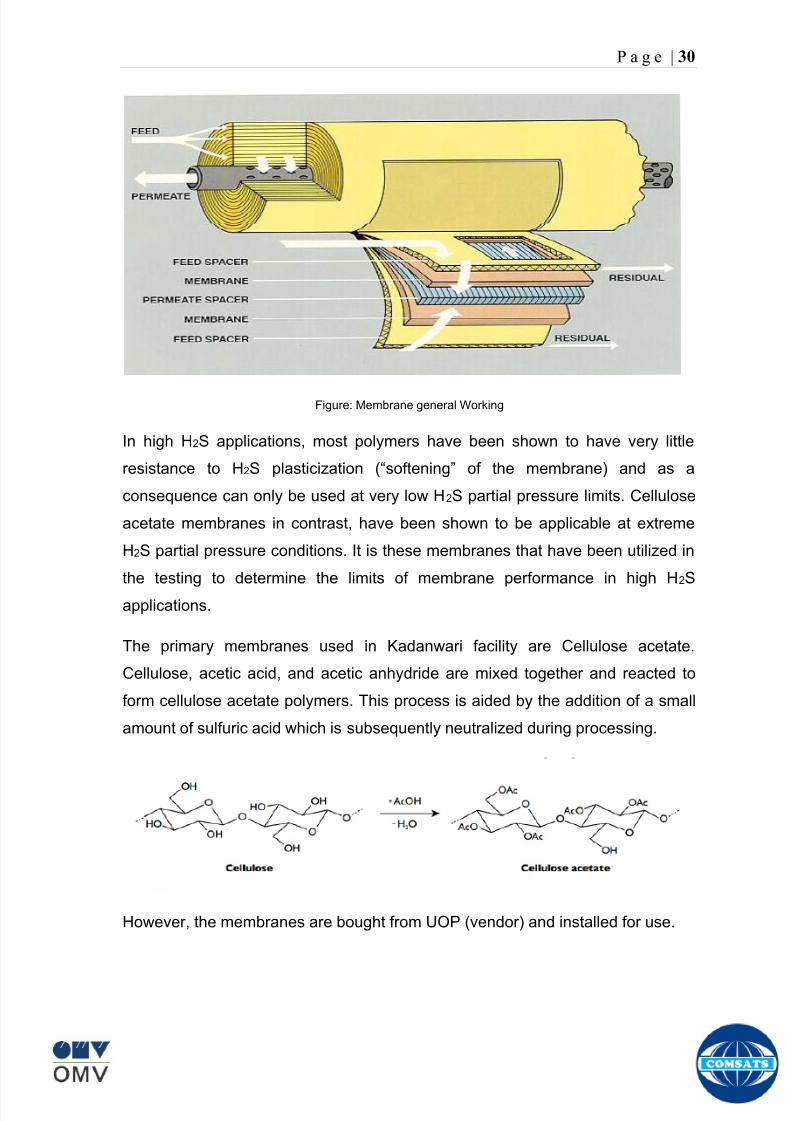
8102019 Gas sweetening Plant
httpslidepdfcomreaderfullgas-sweetening-plant 3462
P a g e | 30
Figure Membrane general Working
In high H2S applications most polymers have been shown to have very little
resistance to H2S plasticization (ldquosofteningrdquo of the membrane) and as a
consequence can only be used at very low H2S partial pressure limits Cellulose
acetate membranes in contrast have been shown to be applicable at extreme
H2S partial pressure conditions It is these membranes that have been utilized in
the testing to determine the limits of membrane performance in high H 2S
applications
The primary membranes used in Kadanwari facility are Cellulose acetate
Cellulose acetic acid and acetic anhydride are mixed together and reacted to
form cellulose acetate polymers This process is aided by the addition of a small
amount of sulfuric acid which is subsequently neutralized during processing
However the membranes are bought from UOP (vendor) and installed for use
8102019 Gas sweetening Plant
httpslidepdfcomreaderfullgas-sweetening-plant 3562
P a g e | 31
How membrane work
The basic principle of separation is selectivity of certain components of a mixture
for the membrane For example the cellulose acetate membrane has very high
selectivity for CO2 and H2S as compared to CH4 Therefore such type of
membrane can be used in gas sweetening process
The selectivity is directly related to the Permeability of gas which accounts that
which gas can pass across the membrane more easily In simple words
membranes being polymer materials are made of long chains of molecules The
different structure of polymer materials only allow selective molecules to pass
through them depending upon chemical and physical compatibility Thus
permeability depends upon choice of polymer
The permeability is determined by permeability coefficient (P) and is product of
solubility (S) and diffusivity (D)
P = S D
Solubility
The solubility is mainly determined by ease of condensation Heavy molecules
are more readily condensed Therefore higher molecular weighted molecules will
more easily condensed and therefore have greater solubility
Molecule Molecular weight
CH4 16
H2S 34
CO2 44
8102019 Gas sweetening Plant
httpslidepdfcomreaderfullgas-sweetening-plant 3662
P a g e | 32
Diffusivity
Diffusivity is ease of molecule to penetrate into some material It depends on size
of gas molecule Here size of molecule is not to be confused by molecular weight
it is the size of the structure Eg the size of O2 molecule is smaller than N2
Molecule Molecular Diameter (Ao)
CO2 33
H2S 36
Ch4 40
For cellulose acetate
DCO2DCH4 S CO2S CH4 P CO2P CH4
45 73 308
Chemical degradation
Cellulose acetate polymer is chemically degraded by a process called hydrolysis
which means breaking apart by the addition of water This is a chemical reaction
in which water is added to the cellulose acetate polymer causing the release of
acetic acid molecules This process proceeds stepwise until all the acetate
groups are released resulting in the reformation of cellulose Moreover alcohols
aromatic hydrocarbons or solvents with chlorine nitro benzene or similar
aromatic solvents will harm the membrane It will expand and lose plastification in
contact with them
Effect of Temperature
The permeation rates of all gases increases with increasing temperature
however membrane selectivity for CO2 over hydrocarbon decreases at higher
8102019 Gas sweetening Plant
httpslidepdfcomreaderfullgas-sweetening-plant 3762
P a g e | 33
temperature Consequently CO2 removal will improve as operating temperature
increases but hydro carbon recovery will decrease
Primary Membrane
The primary membranes comprise of two trains Each train consists of two
sections AB and CD each section consists of a 30 tube membrane skid (A and
C) followed by a 25 tube skid (B and D) The conditioned gas (after pre-
treatment) enters the primary membrane via the particulate filter adjacent to the
skid The gas is fed to the membranes through a common inlet manifold which
supplies primary membranes skids A and C A pressure control loop located
upstream of the manual inlet isolation valve is provided to maintain a constant
supply pressure to the membrane skid and to allow for preheating at the inlet
prior to skid start-up This pressure control loop can also be used during start-up
to control the pressurization of the pretreatment skid and associated pipes to the
primary membranes
The gas passes through membrane skid A the residual gas exiting the membrane
skid is sent to skid B and the permeate to common permeate discharge header An
identical arrangement is provide on the inlet to skid C as provided on skid A Theresidual gas from skid B combines with the residual gas from skid D in a common
discharge header and is then sent to the H2S polishing towers via the feed coolers
on the pre-treatment skid The permeate from skid B is sent to the common
permeate discharge header The permeate discharge header sends the gas to
either the recycle compressor or the vent header via a pressure control loop
Overpressure protection for the membranes is provided by a pressure safety valve
on the supply header to the membrane banks
8102019 Gas sweetening Plant
httpslidepdfcomreaderfullgas-sweetening-plant 3862
P a g e | 34
Secondary (Recycle) Membrane
The recycle membranes comprise of a single train with two skids each with four
banks of membrane tubes The conditioned gas from the discharge of the recycle
pre-treatment skid is routed to the first recycle membrane skid The gas passes
through the membranes the residual gas is fed to primary membrane (skid A) inlet
via feed gas cooler and permeate to the common permeate discharge header An
identical arrangement is provide on the inlet to skid B Permeate from the recycle
membrane skids A and B is routed to the vent header Some portion of permeate is
heated and sent for regeneration in Mem-Guard units Nitrogen purge can be
connected downstream of the inlet isolation valve on each skid to enable the
membrane tubes to be purged and left pressurized during prolonged shutdown
8102019 Gas sweetening Plant
httpslidepdfcomreaderfullgas-sweetening-plant 3962
P a g e | 35
Figure Flow Diagram of Recycle membrane unit
8102019 Gas sweetening Plant
httpslidepdfcomreaderfullgas-sweetening-plant 4062
P a g e | 36
ADVANTAGES OF MEMBRANE SYSTEMS
Membrane systems have major advantages over more-traditional methods of
acid gas removal
Lower capital cost Membrane systems are skid mounted and so the
scope cost and time taken for site preparation are minimal Installation
costs are significantly lower than alternative technologies especially for
remote areas Furthermore no additional facilities for solvent storage and
water treatment needed by other processes are required
Lower operating costs The only major operating cost for single-stage
membrane systems is membrane replacement This cost is significantly
lower than the solvent replacement and energy costs associated with
traditional technologies The improvements in membrane and
pretreatment design allow a longer useful membrane life which further
reduces operating costs The energy costs of multistage systems with
large recycle compressors are usually comparable to those for traditionaltechnologies
Deferred capital investment Often contracted sales-gas flow rates
increase over time as more wells are brought on-line With traditional
technologies the system design needs to take this later production into
account immediately and so the majority of the equipment is installed
before it is even needed The modular nature of membrane systems
means that only the membranes that are needed at start-up need be
installed The rest can be added either into existing tubes or in new skids
only when they are required
Operational simplicity and high reliability Because single-stage
membrane systems have no moving parts they have almost no
8102019 Gas sweetening Plant
httpslidepdfcomreaderfullgas-sweetening-plant 4162
P a g e | 37
unscheduled downtime and are extremely simple to operate They can
operate unattended for long periods of time The addition of a recycle
compressor adds some complexity to the system but still much less than
with a solvent- or adsorbent-based technology Multistage systems can be
operated at full capacity as single-stage systems when the recycle
compressor is down
Good weight and space efficiency Skid construction can be optimized
to the space available This space efficiency is especially important for
offshore environments where deck area is at a premium and is the
reason why so many new offshore developments have chosen to use
membranes for acid gas removal Figure 6 illustrates the space efficiency
of membrane systems The membrane unit in the lower left corner
replaced all the amine and glycol plant equipment shown in the rest of the
picture
Adaptability Because membrane area is dictated by the percentage of
acid gas removal rather than absolute acid gas removal small variations
in feed acid gas content hardly change the sales-gas acid gas
specification For example a system designed for 10 down to 3 acid
gas removal produces a 35 product from a 12 feed gas and a 5
product from a 15 feed gas
Design efficiency The membrane and pretreatment systems integrate a
number of operations such as dehydration CO2 and H2S removal dew-
point control and mercury removal Traditional acid gas removal
technologies require all of these operations as separate processes and
may also require additional dehydration because some technologies
saturate the product stream with water
8102019 Gas sweetening Plant
httpslidepdfcomreaderfullgas-sweetening-plant 4262
P a g e | 38
Power generation The permeate gas from membrane systems can be
used to provide fuel gas for power generation either for a recycle
compressor or other equipment
Ideal for debottlenecking Because expanding solvent- or adsorbent-
based acid gas removal plants without adding additional trains is difficult
an ideal solution is to use membranes for bulk acid gas removal and leave
the existing plant for final cleanup An additional advantage is that the
permeate gas from the membrane system can often be used as fuel for
the existing plant thus avoiding significant increase in hydrocarbon
losses
Environmentally friendly Membrane systems do not involve the
periodic removal and handling of spent solvents or adsorbents Permeate
gases can be flared used as fuel or re-injected into the well Items thatdo need disposal such as spent membrane elements can be incinerated
Ideal for remote locations Many of the factors mentioned above make
membrane systems a highly desirable technology for remote locations
where spare parts are rare and labor unskilled Furthermore solvents
storage and trucking water supply power generation or extensive
infrastructure are not required
Re-injection optimizations Since the permeate stream from the
membrane system can be operated at elevated pressures it is possible to
further pressurize by re-injection compression train
8102019 Gas sweetening Plant
httpslidepdfcomreaderfullgas-sweetening-plant 4362
P a g e | 39
Sorption
Sorption is a physical and chemical process by which one substance becomes
attached to another
It is of two main types
1 Absorption
2 Adsorption
Absorption
Absorption is a physical or chemical phenomenon or process in which atoms
molecules or ions enter some bulk phase ndash gas liquid or solid material This is a
different process from adsorption since molecules undergoing absorption are
taken up by the volume not by the surface (as in the case for adsorption)
Absorption process may be chemical (reactive) or physical (non-reactive)
Physical absorption
Physical absorption or non-reactive absorption is made between two phases ofmatter a liquid absorbs a gas or a solid absorbs a liquid
When a liquid solvent absorbs a gas mixture or part of it a mass of gas moves
into the liquid For example water may absorb oxygen from the air This mass
transfer takes place at the interface between the liquid and the gas at a rate
depending on both the gas and the liquid This type of absorption depends on the
solubility of gases the pressure and the temperature The rate and amount of
absorption also depend on the surface area of the interface and its duration in
time
When a solid absorbs a liquid mixture or part of it a mass of liquid moves into the
solid For example a clay pot used to store water may absorb some of the water
This mass transfer takes place at the interface between the solid and the liquid
at a rate depending on both the solid and the liquid
8102019 Gas sweetening Plant
httpslidepdfcomreaderfullgas-sweetening-plant 4462
P a g e | 40
Chemical absorption
Chemical absorption or reactive absorption is a chemical reaction between the
absorbed and the absorbing substances Sometimes it combines with physical
absorption This type of absorption depends upon the stoichiometry of the
reaction and the concentration of its reactants
Adsorption
Adsorption is the adhesion of atoms ions or molecules from a gas liquid or
dissolved solid to a surface This process creates a film of the adsorbate on the
surface of the adsorbent The binding to the surface is usually weak and
reversible Compounds with color and those that have taste or odor tend to bind
strongly Compounds that vibrate at frequencies in the visible spectrum are very
often are strongly adsorbed on activated carbon
The most common industrial adsorbents are activated carbon silica gel and
alumina because they present enormous surface areas per unit weight
Depending on the nature of attractive forces existing between the adsorbate and
adsorbent adsorption can be classified as
i) Physical adsorption
ii) Chemical adsorption
i) Physical adsorption (Physisorption)
In physical adsorption the forces of attraction between the molecules of the
adsorbate and the adsorbent are of the weak van der Waals type Since the
forces of attraction are weak the process of physisorption can be easily reversed
by heating or decreasing the pressure of the adsorbate (as in the case of gases)
8102019 Gas sweetening Plant
httpslidepdfcomreaderfullgas-sweetening-plant 4562
P a g e | 41
ii) Chemical adsorption (Chemisorption)
In chemisorption the forces of attraction between the adsorbate and the
adsorbent are very strong the molecules of adsorbate form chemical bonds with
the molecules of the adsorbent present in the surface
Adsorption is generally accompanied by release of energy that is most
adsorption processes are exothermic in nature Adsorption is a spontaneous
process therefore its free energy change is negative (∆Glt0) However the
entropy change associated with adsorption is generally negative because the
adsorbate molecules lose their translation freedom when they get attached to the
surface of the adsorbent Therefore in order for ∆G to be negative the enthalpy
change (∆H) must be sufficiently negative such that (∆G=∆H-T∆S) lt 0 This
explanation accounts for exothermic adsorption processes In cases where
endothermic adsorption occurs the entropy change ∆S is sufficiently positive
such that ∆G remains negative
Pre treatment
The main function of pretreatment skid is to provide membrane inlet specification
gas as mentioned by the vendor UOP It removes the contaminants that would
poison the membranes like dust solids (adsorbent particles) lube oil heavy
hydrocarbons etc It consists of
Feed Cooler
Feed Gas Scrubber
Filter Coalescer
Feed Gas Heater
Activated Carbon Guard Filter
Particle Filter
8102019 Gas sweetening Plant
httpslidepdfcomreaderfullgas-sweetening-plant 4662
8102019 Gas sweetening Plant
httpslidepdfcomreaderfullgas-sweetening-plant 4762
P a g e | 43
The regeneration is carried out by heated permeate gas from the recycle
membranes at 450oF The vessel is depressurized to 20 psi and heated gas is
introduced from top The gas carries out the adsorbed contaminants and leaves
the vessel from bottom cleaning the adsorbent This contaminated gas is burnt in
the flare
UOP the vendor of Memguard unit has never disclosed that what substance
MG3 and MG5 exactly are But as mentioned by vendor that both care class of
aluminosilicates Therefore MG3 can be potassium aluminosilicate and MG5 can
be Calcium aluminosilicate These are molecular sieves adsorbents Molecular
sieves are a microporous material which can selectively adsorb gases andliquids They are synthetic zeolites (crystalline metal aluminosilicates) which
upon dehydration can efficiently and selectively remove water or other
solvents The selectivity of a molecular sieve is determined by its pore size
molecules with a critical diameter which is less than the pore size will be
efficiently adsorbed while larger molecules will be excluded
8102019 Gas sweetening Plant
httpslidepdfcomreaderfullgas-sweetening-plant 4862
P a g e | 44
3A Molecular Sieve Adsorbent
The 3A molecular sieve adsorbent has a 3 angstrom (3A) pore size which means
that any molecule that is larger than the 3 angstrom pores will not be adsorbed
The 3A molecular sieve is the potassium type of A crystalline structure and is a
form of alkali Aluminosilicate For a 3A molecular sieve the sequence rate that
adsorption occurs is He Ne N and H2O
Due to the crystalline structure molecular sieves that have a 3 angstrom pore
size have a very high rate of adsorption and properties that promote a longer life
for products treated by the sieve The most common use for the 3A molecular
sieve is to remove water and moisture from materials that are in gas and liquid
form
5A Molecular Sieve Adsorbent
These are molecular sieve adsorbents with a pore size of 5 angstrom (5A) 5A
molecular sieves are unable to adsorb any molecules or impurities that are
smaller than 5A It is calcium form of type A crystalline structure and is form of analkali-aluminosilicate that is most commonly used to separate isomerous alkanes
from normal alkanes and to co-adsorb moisture and water along with carbon
dioxide from gases In additional 5A molecular sieves are used for gaseous
pressure swing adsorption (PSA)mdashthat is to separate particular gases from other
gases
Adsorption of nC4H10
Adsorption of nC4H10
Adsorption of C3H8 to C22H46
Adsorption of Freon-12 (dichlorodifluoromethane)
Natural gas drying
Normal- and iso-paraffin separation
Separation of aromatic
8102019 Gas sweetening Plant
httpslidepdfcomreaderfullgas-sweetening-plant 4962
P a g e | 45
Inlet Composition of Memguard vessel
COMPSOSITION MOLE
CARBON DIOXIDE 1096
MEHTANE 8593
ETHANE 173
PROPANE 023
I-BUTANE 008
N BUTANE 004
PENTANES 004
HEXANE + 000
NITROGEN 076
WATER 007
Outlet Composition of Memguard vessel
COMPSOSITION MOLE
CARBON DIOXIDE 1098
MEHTANE 8608
ETHANE 173
PROPANE 023
I-BUTANE 008N BUTANE 004
PENTANES 004
HEXANE + 000
NITROGENT 076
WATER 000
H2S polisher
The H2S polishing unit has been designed to treat 187 MMscfday of natural gas
containing up to 11 CO2 and 21 ppm H2S where the level of the CO2 and H2S
is reduced using a MemGuard Membrane separation unit The unit is situated
down-stream of the membrane unit and will further reduce the level of H2S in the
processed gas to a sales gas specification of 38 ppm
8102019 Gas sweetening Plant
httpslidepdfcomreaderfullgas-sweetening-plant 5062
P a g e | 46
This process uses three non-regenerable fixed bed absorber vessels using a low
temperature high activity absorbent The absorbent is a mixture of activated
metal oxides (mainly zinc oxide) The three towers can are generally operated in
parallel arrangement but on demand can be used in series (any of alternate
arrangements of A B C vessels) as shown in figure
The higher sales gas flow rate increased the catalyst consumption and
replacement frequency
ZnO + H2S =gt ZnS + H20
Routine samples are taken from the beds to provide a check on each bed
performance and to follow the saturation profile during the absorbent life After
the adsorbent has been fully utilized the adsorption vessels are recharged with
new adsorbent discarding the utilized one in a safe manner
109oF
1215 psig
Before H2S Polishing After H2S Polishing
8102019 Gas sweetening Plant
httpslidepdfcomreaderfullgas-sweetening-plant 5162
P a g e | 47
Figure
H2S Tower
Inlet pipe
4 Drums of 19mm
ceramic Balls
6 Micron mesh
5 Drums of 50mmceramic
1 Drums of19mm ceramic
01 Drums of6mm ceramic
112 drums of
Catalist ZnO
8102019 Gas sweetening Plant
httpslidepdfcomreaderfullgas-sweetening-plant 5262
P a g e | 48
Recycle Compressor
The permeate gas of the primary membrane unit carries recoverable amount of
CH4 It is fed to recycle membrane unit for further CH 4 recovery But the
permeate pressure from primary membranes which has been reduced to 12 psi
must be regenerated to 1200 psi for the gas to be fed again to the system For
this purpose we have employed recycle compressor The compressor is a four
stage centrifugal compressor It is driven by gas turbine of 31200 HP It has 25
MW producing capacity
Figure Recycle Compressor Process Flow Diagram
8102019 Gas sweetening Plant
httpslidepdfcomreaderfullgas-sweetening-plant 5362
P a g e | 49
Sales Gas Compressor
Gas from H2S polishing unit is sent to sales gas compressor where its pressure
is enhanced to 1100 psi so it may be injected to SNGPL high pressure trunk line
Sales gas compressor is single stage gas turbine driven
Figure Process Flow of Sales Gas Compressor
8102019 Gas sweetening Plant
httpslidepdfcomreaderfullgas-sweetening-plant 5462
P a g e | 50
Cooling Towers
A cooling tower is a heat rejection device which extracts waste heat to theatmosphere through the cooling of a water stream to a lower temperature Hot
water from the system enters the cooling tower and is distributed over the fill
(heat transfer surface) Air is induced or forced through the fill causing a small
portion of the water to evaporate This evaporation removes heat from the
remaining water which is collected in the cold water basin and returned to the
system to absorb more heat Each cooling tower line although operating under
the same basic principle of operation is arranged a little differently
Types
Natural draft mdash Utilizes buoyancy via a tall chimney Warm moist air naturally
rises due to the density differential compared to the dry cooler outside air Warm
moist air is less dense than drier air at the same pressure This moist air
buoyancy produces an upwards current of air through the tower
Mechanical draft mdash Uses power-driven fan motors to force or draw airthrough the tower
o Induced draft mdash A mechanical draft tower with a fan at the
discharge (at the top) which pulls air up through the tower The fan
induces hot moist air out the discharge This produces low entering
and high exiting air velocities reducing the possibility of
recirculation in which discharged air flows back into the air intake
o Forced draft mdash A mechanical draft tower with a blower type fan at
the intake The fan forces air into the tower creating high entering
and low exiting air velocities The low exiting velocity is much more
susceptible to recirculation This fanfill geometry is also known as
blow-through
8102019 Gas sweetening Plant
httpslidepdfcomreaderfullgas-sweetening-plant 5562
P a g e | 51
Forced Draft Cooling Tower Vs Induced Draft Cooling Tower
Induced Draft Cooling Tower have the ability to handle large water flow
rate than Forced Draft Cooling Tower
Induced Draft Cooling Tower is suitable for large cell sizes and fan sizes
as compared with Forced Draft Larger fan size may result in greater
efficiency and consequently lower power and sound level
Forced Draft Cooling Tower can be square or rectangular type only
however Induced Draft Cooling Towers can be round square or
rectangular type
Induced Draft Cooling Tower uses more compact ground area than Forced
Draft Cooling Tower equivalent capacity due to absence of fan on one
side
Fan equipment is warm exhaust air is less liable to icing up in winter
operation (Cold Countries)
Higher velocity in Forced Draft Cooling Tower cause drop in suspension
and cause additional static resistance to system
Configuration
There are two main configurations of factory assembled cooling towers crossflow
and counterflow In crossflow cooling towers the water flows vertically down the
fill as air flows horizontally across In counterflow cooling towers the water flows
vertically down the fill as air flows vertically up
Crossflow Configuration Counterflow Configuration
8102019 Gas sweetening Plant
httpslidepdfcomreaderfullgas-sweetening-plant 5662
P a g e | 52
Drift mdash Water droplets that are carried out of the cooling tower with the exhaust
air Drift droplets have the same concentration of impurities as the water entering
the tower The drift rate is typically reduced by employing baffle-like devices
called drift eliminators through which the air must travel after leaving the fill and
spray zones of the tower
Blow-out mdash Water droplets blown out of the cooling tower by wind generally at
the air inlet openings Water may also be lost in the absence of wind through
splashing or misting Devices such as wind screens louvers splash deflectors
and water diverters are used to limit these losses
Blow-down mdash The portion of the circulating water flow that is removed (usually
discharged to a drain) in order to maintain the amount of Total Dissolved Solids
(TDS) and other impurities at an acceptably low level Higher TDS concentration
in solution may result from greater cooling tower efficiency However the higher
the TDS concentration the greater the risk of scale biological growth and
corrosion
Make-up mdash The water that must be added to the circulating water system in
order to compensate for water losses such as evaporation drift loss blow-out
blow-down etc
Approach mdash The approach is the difference in temperature between the cooled-
water temperature and the entering-air wet bulb temperature
Range mdash The range is the temperature difference between the warm water inlet
and cooled water exit
Fill mdash Inside the tower fills are added to increase contact surface as well as
contact time between air and water to provide better heat transfer The efficiency
of the tower depends on the selection and amount of fill
8102019 Gas sweetening Plant
httpslidepdfcomreaderfullgas-sweetening-plant 5762
P a g e | 53
There are two types of fills that may be used
o Film type fill (causes water to spread into a thin film)
o Splash type fill (breaks up falling stream of water and interrupts its
vertical progress)
Important
Scale build up is controlled by adding chemicals to the cooling loop and diluting
the concentration by blow down and make-up Following chemicals are added to
the Cooling to control CorrosionSale and microbial growth
Corrosion Inhibitor To control corrosion in the Cooling system
Dispersant To kept ions in suspension to avoid settle down and buildup
Sodium hypo Chlorite To Control microbial Growth
Acid To control Alkalinity in the system
High Stress Polymer To run the system at higher conductivity It is a
multifunctional polymer for Zinc amp Phosphate stabilization in cooling tower
Fin Fan Cooler
Fin fan heat exchanger is simply a pressure vessel which cools a circulating fluid
within finned tubes by forcing ambient air over the exterior of the tubes A
common example of an air cooler is a carrsquos radiator Fin Fan Coolers are used in
any application where large quantities of heat need to be transferred This
includes chemical and petrochemical industries power stations waste-to-energy
facilities as well as steelworks
Fin Fan Cooler are used for two primary reasons
They increase plant efficiency
They are a green solution as compared to cooling towers and shell and
tube heat exchangers because they do not require an auxiliary water
8102019 Gas sweetening Plant
httpslidepdfcomreaderfullgas-sweetening-plant 5862
P a g e | 54
supply (water lost due to drift and evaporation plus no water treatment
chemicals are required)
Figure General Overview of Fin Fan Cooler
Produced Water
The produced water system receives liquid from the equipment Miano slug
catcher train 1 and 2 inlet separators and is fed to three phase separator where
water oil and gas is separated The gases produced are burnt in incinerator
whereas hydrocarbon liquid is stored to be sold Liquid from compressors
recycle inlet separator recycle feed scrubber high and low pressure slug
catchers is passed to degasser Separated water is injected down the earth
Incinerator
The term incinerate means to burn something until nothing is left but ashes An
incinerator is a unit or facility used to burn trash and other types of waste until it is
reduced to ash An incinerator is constructed of heavy well-insulated materials
so that it does not give off extreme amounts of external heat The high levels of
heat are kept inside the furnace or unit so that the waste is burned quickly and
efficiently If the heat were allowed to escape the waste would not burn as
completely or as rapidly
8102019 Gas sweetening Plant
httpslidepdfcomreaderfullgas-sweetening-plant 5962
P a g e | 55
Control System
The plant is controlled at CCR (Central Control Room) by PLCs (Programmable
Logic Controllers) through fiber optic control line All control parameters are
received at LER (Local Equipment Room) via two optic fiber control lines One
being primary and other secondary operating in redundancy ie if primary fails
control shifts to secondary These control parameters are sent to CCR via single
optic fiber cable
Safety System
Wellheads and Gas Processing Plant have their own Fire amp Gas detection
systems emergency shutdown (ESD) Plant has a fault tolerant controller It is
based on Triple Modular Redundant (TMR) architecture manufactured by
Triconex The TMR system is based on three isolated parallel control systems
integrated into one system The system operates on a two out of three voting
principle which provides high integrity error free uninterrupted operation with no
single point of failure The TMR receives inputs from Process Sensors Manual
Switches Fire amp Gas Detectors Packaged Equipment Control Systems and
Product Exporting Facilities The TMR carries out cause and effect processing on
the data received and where necessary produces output signals Outputs from
the TMR are hard wired directly to ESD shutdown and blow down valve
solenoids motor control instrumentelectrical interfaces to control electrical
drives package equipment logic control systems manifold area as well as
telecoms
The operator in central control room is able to accept alarms and once the fault
has been cleared reset the input All the control systems are centralized to a
single interface All the PLCs (Programmable Logic Controllers) communicate with
the servers and servers communicate with the clients through Ethernet connectivity
Centralization eases the navigation of different systems at a common interface
Emergency Shutdown
The ESD system receives inputs from field mounted instrumentation on the process
8102019 Gas sweetening Plant
httpslidepdfcomreaderfullgas-sweetening-plant 6062
P a g e | 56
and utility equipment and initiates executive actions appropriate to the level of ESD
The system is an Active system which is in standby and will activate when in an
alarm or fault condition The Kadanwari Gas Process Facility ESD system is
comprised of five (5) levels The emergency severity decreases with increasing ESD
level number
ESD 1
This shutdown level is automatically initiated by fire major gas leak or a detected
toxic atmosphere in the process area of the plant or manually from CCR A level 1
shutdown will cause all production to cease close all emergency shutdown
valves stop the process and shutdown of the main power generation The
emergency vent valves to the stack will open and in addition all equipment of zone 1
certified will be isolated This is the highest level of ESD and will cause the following
to occur
All Shutdown Valves (SDVs) on the process facility will close All slowdown Valves (BDVs) on the process facility will open
All Main Gas Driven Generators will be tripped
Emergency Diesel Generator will start
All electrical power to process and utility rotating equipment will be
isolated
Wellhead Choke Valves Close Wing Valves Close Upper Master Valve
(UMV) Close
ESD 2
This shutdown level is activated automatically if a major process or utility failure
occurs or manually from CCR All production to the plant from the wellhead is
stopped All emergency shutdown valves trip to their fail safe position
Venting shall be as specified This level of ESD will cause the following to occur
8102019 Gas sweetening Plant
httpslidepdfcomreaderfullgas-sweetening-plant 6162
P a g e | 57
All Shutdown Valves (SDVs) on the process facility will close
All electrical power to process and utility rotating equipment will be
isolated
Wellhead Choke Valve Close Wing Valves Close and Upper Master Valve(UMV) Close
ESD 3
The level 3 shutdown isolates and stops a single process train only Production
continues via the other train This ESD level is initiated by process conditions or
operator at local panel This level of ESD will cause the following to occur
ESD 3A Train 1 production to cease
ESD 3B Train 2 production to cease
All online wellhead choke valves go to minimum flow ie (1O )
ESD 4
A level 4 shutdown shall cease all production from an entire field either
Kadanwari or Miano upstream of the associated slug catchers ESD 4K for
Kadanwari amp ESD 4M for Miano This ESD level is initiated automatically by slug
catcher abnormal process conditions This level of ESD will cause the following
to occur
All SDVs close isolating the relevant slug catcher and its upstream gas
production facility from the Kadanwari Gas Processing Plant
All Wellhead Choke Valves Close Wing Valves Close and Upper MasterValves (UMV) of the relevant gas production facility Close
A parallel timer is provided to close within 10 second if not closed in given
time SSSV seals the well
ESD 5
A level 5 shutdown represents equipment shutdown for the protection of the
individual equipment without any change in the process This level of ESD is for the
protection of various pieces of equipment and is initiated by its own inputs eg
8102019 Gas sweetening Plant
httpslidepdfcomreaderfullgas-sweetening-plant 6262
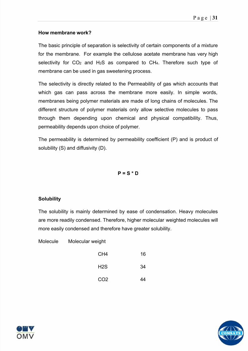
8102019 Gas sweetening Plant
httpslidepdfcomreaderfullgas-sweetening-plant 3562
P a g e | 31
How membrane work
The basic principle of separation is selectivity of certain components of a mixture
for the membrane For example the cellulose acetate membrane has very high
selectivity for CO2 and H2S as compared to CH4 Therefore such type of
membrane can be used in gas sweetening process
The selectivity is directly related to the Permeability of gas which accounts that
which gas can pass across the membrane more easily In simple words
membranes being polymer materials are made of long chains of molecules The
different structure of polymer materials only allow selective molecules to pass
through them depending upon chemical and physical compatibility Thus
permeability depends upon choice of polymer
The permeability is determined by permeability coefficient (P) and is product of
solubility (S) and diffusivity (D)
P = S D
Solubility
The solubility is mainly determined by ease of condensation Heavy molecules
are more readily condensed Therefore higher molecular weighted molecules will
more easily condensed and therefore have greater solubility
Molecule Molecular weight
CH4 16
H2S 34
CO2 44
8102019 Gas sweetening Plant
httpslidepdfcomreaderfullgas-sweetening-plant 3662
P a g e | 32
Diffusivity
Diffusivity is ease of molecule to penetrate into some material It depends on size
of gas molecule Here size of molecule is not to be confused by molecular weight
it is the size of the structure Eg the size of O2 molecule is smaller than N2
Molecule Molecular Diameter (Ao)
CO2 33
H2S 36
Ch4 40
For cellulose acetate
DCO2DCH4 S CO2S CH4 P CO2P CH4
45 73 308
Chemical degradation
Cellulose acetate polymer is chemically degraded by a process called hydrolysis
which means breaking apart by the addition of water This is a chemical reaction
in which water is added to the cellulose acetate polymer causing the release of
acetic acid molecules This process proceeds stepwise until all the acetate
groups are released resulting in the reformation of cellulose Moreover alcohols
aromatic hydrocarbons or solvents with chlorine nitro benzene or similar
aromatic solvents will harm the membrane It will expand and lose plastification in
contact with them
Effect of Temperature
The permeation rates of all gases increases with increasing temperature
however membrane selectivity for CO2 over hydrocarbon decreases at higher
8102019 Gas sweetening Plant
httpslidepdfcomreaderfullgas-sweetening-plant 3762
P a g e | 33
temperature Consequently CO2 removal will improve as operating temperature
increases but hydro carbon recovery will decrease
Primary Membrane
The primary membranes comprise of two trains Each train consists of two
sections AB and CD each section consists of a 30 tube membrane skid (A and
C) followed by a 25 tube skid (B and D) The conditioned gas (after pre-
treatment) enters the primary membrane via the particulate filter adjacent to the
skid The gas is fed to the membranes through a common inlet manifold which
supplies primary membranes skids A and C A pressure control loop located
upstream of the manual inlet isolation valve is provided to maintain a constant
supply pressure to the membrane skid and to allow for preheating at the inlet
prior to skid start-up This pressure control loop can also be used during start-up
to control the pressurization of the pretreatment skid and associated pipes to the
primary membranes
The gas passes through membrane skid A the residual gas exiting the membrane
skid is sent to skid B and the permeate to common permeate discharge header An
identical arrangement is provide on the inlet to skid C as provided on skid A Theresidual gas from skid B combines with the residual gas from skid D in a common
discharge header and is then sent to the H2S polishing towers via the feed coolers
on the pre-treatment skid The permeate from skid B is sent to the common
permeate discharge header The permeate discharge header sends the gas to
either the recycle compressor or the vent header via a pressure control loop
Overpressure protection for the membranes is provided by a pressure safety valve
on the supply header to the membrane banks
8102019 Gas sweetening Plant
httpslidepdfcomreaderfullgas-sweetening-plant 3862
P a g e | 34
Secondary (Recycle) Membrane
The recycle membranes comprise of a single train with two skids each with four
banks of membrane tubes The conditioned gas from the discharge of the recycle
pre-treatment skid is routed to the first recycle membrane skid The gas passes
through the membranes the residual gas is fed to primary membrane (skid A) inlet
via feed gas cooler and permeate to the common permeate discharge header An
identical arrangement is provide on the inlet to skid B Permeate from the recycle
membrane skids A and B is routed to the vent header Some portion of permeate is
heated and sent for regeneration in Mem-Guard units Nitrogen purge can be
connected downstream of the inlet isolation valve on each skid to enable the
membrane tubes to be purged and left pressurized during prolonged shutdown
8102019 Gas sweetening Plant
httpslidepdfcomreaderfullgas-sweetening-plant 3962
P a g e | 35
Figure Flow Diagram of Recycle membrane unit
8102019 Gas sweetening Plant
httpslidepdfcomreaderfullgas-sweetening-plant 4062
P a g e | 36
ADVANTAGES OF MEMBRANE SYSTEMS
Membrane systems have major advantages over more-traditional methods of
acid gas removal
Lower capital cost Membrane systems are skid mounted and so the
scope cost and time taken for site preparation are minimal Installation
costs are significantly lower than alternative technologies especially for
remote areas Furthermore no additional facilities for solvent storage and
water treatment needed by other processes are required
Lower operating costs The only major operating cost for single-stage
membrane systems is membrane replacement This cost is significantly
lower than the solvent replacement and energy costs associated with
traditional technologies The improvements in membrane and
pretreatment design allow a longer useful membrane life which further
reduces operating costs The energy costs of multistage systems with
large recycle compressors are usually comparable to those for traditionaltechnologies
Deferred capital investment Often contracted sales-gas flow rates
increase over time as more wells are brought on-line With traditional
technologies the system design needs to take this later production into
account immediately and so the majority of the equipment is installed
before it is even needed The modular nature of membrane systems
means that only the membranes that are needed at start-up need be
installed The rest can be added either into existing tubes or in new skids
only when they are required
Operational simplicity and high reliability Because single-stage
membrane systems have no moving parts they have almost no
8102019 Gas sweetening Plant
httpslidepdfcomreaderfullgas-sweetening-plant 4162
P a g e | 37
unscheduled downtime and are extremely simple to operate They can
operate unattended for long periods of time The addition of a recycle
compressor adds some complexity to the system but still much less than
with a solvent- or adsorbent-based technology Multistage systems can be
operated at full capacity as single-stage systems when the recycle
compressor is down
Good weight and space efficiency Skid construction can be optimized
to the space available This space efficiency is especially important for
offshore environments where deck area is at a premium and is the
reason why so many new offshore developments have chosen to use
membranes for acid gas removal Figure 6 illustrates the space efficiency
of membrane systems The membrane unit in the lower left corner
replaced all the amine and glycol plant equipment shown in the rest of the
picture
Adaptability Because membrane area is dictated by the percentage of
acid gas removal rather than absolute acid gas removal small variations
in feed acid gas content hardly change the sales-gas acid gas
specification For example a system designed for 10 down to 3 acid
gas removal produces a 35 product from a 12 feed gas and a 5
product from a 15 feed gas
Design efficiency The membrane and pretreatment systems integrate a
number of operations such as dehydration CO2 and H2S removal dew-
point control and mercury removal Traditional acid gas removal
technologies require all of these operations as separate processes and
may also require additional dehydration because some technologies
saturate the product stream with water
8102019 Gas sweetening Plant
httpslidepdfcomreaderfullgas-sweetening-plant 4262
P a g e | 38
Power generation The permeate gas from membrane systems can be
used to provide fuel gas for power generation either for a recycle
compressor or other equipment
Ideal for debottlenecking Because expanding solvent- or adsorbent-
based acid gas removal plants without adding additional trains is difficult
an ideal solution is to use membranes for bulk acid gas removal and leave
the existing plant for final cleanup An additional advantage is that the
permeate gas from the membrane system can often be used as fuel for
the existing plant thus avoiding significant increase in hydrocarbon
losses
Environmentally friendly Membrane systems do not involve the
periodic removal and handling of spent solvents or adsorbents Permeate
gases can be flared used as fuel or re-injected into the well Items thatdo need disposal such as spent membrane elements can be incinerated
Ideal for remote locations Many of the factors mentioned above make
membrane systems a highly desirable technology for remote locations
where spare parts are rare and labor unskilled Furthermore solvents
storage and trucking water supply power generation or extensive
infrastructure are not required
Re-injection optimizations Since the permeate stream from the
membrane system can be operated at elevated pressures it is possible to
further pressurize by re-injection compression train
8102019 Gas sweetening Plant
httpslidepdfcomreaderfullgas-sweetening-plant 4362
P a g e | 39
Sorption
Sorption is a physical and chemical process by which one substance becomes
attached to another
It is of two main types
1 Absorption
2 Adsorption
Absorption
Absorption is a physical or chemical phenomenon or process in which atoms
molecules or ions enter some bulk phase ndash gas liquid or solid material This is a
different process from adsorption since molecules undergoing absorption are
taken up by the volume not by the surface (as in the case for adsorption)
Absorption process may be chemical (reactive) or physical (non-reactive)
Physical absorption
Physical absorption or non-reactive absorption is made between two phases ofmatter a liquid absorbs a gas or a solid absorbs a liquid
When a liquid solvent absorbs a gas mixture or part of it a mass of gas moves
into the liquid For example water may absorb oxygen from the air This mass
transfer takes place at the interface between the liquid and the gas at a rate
depending on both the gas and the liquid This type of absorption depends on the
solubility of gases the pressure and the temperature The rate and amount of
absorption also depend on the surface area of the interface and its duration in
time
When a solid absorbs a liquid mixture or part of it a mass of liquid moves into the
solid For example a clay pot used to store water may absorb some of the water
This mass transfer takes place at the interface between the solid and the liquid
at a rate depending on both the solid and the liquid
8102019 Gas sweetening Plant
httpslidepdfcomreaderfullgas-sweetening-plant 4462
P a g e | 40
Chemical absorption
Chemical absorption or reactive absorption is a chemical reaction between the
absorbed and the absorbing substances Sometimes it combines with physical
absorption This type of absorption depends upon the stoichiometry of the
reaction and the concentration of its reactants
Adsorption
Adsorption is the adhesion of atoms ions or molecules from a gas liquid or
dissolved solid to a surface This process creates a film of the adsorbate on the
surface of the adsorbent The binding to the surface is usually weak and
reversible Compounds with color and those that have taste or odor tend to bind
strongly Compounds that vibrate at frequencies in the visible spectrum are very
often are strongly adsorbed on activated carbon
The most common industrial adsorbents are activated carbon silica gel and
alumina because they present enormous surface areas per unit weight
Depending on the nature of attractive forces existing between the adsorbate and
adsorbent adsorption can be classified as
i) Physical adsorption
ii) Chemical adsorption
i) Physical adsorption (Physisorption)
In physical adsorption the forces of attraction between the molecules of the
adsorbate and the adsorbent are of the weak van der Waals type Since the
forces of attraction are weak the process of physisorption can be easily reversed
by heating or decreasing the pressure of the adsorbate (as in the case of gases)
8102019 Gas sweetening Plant
httpslidepdfcomreaderfullgas-sweetening-plant 4562
P a g e | 41
ii) Chemical adsorption (Chemisorption)
In chemisorption the forces of attraction between the adsorbate and the
adsorbent are very strong the molecules of adsorbate form chemical bonds with
the molecules of the adsorbent present in the surface
Adsorption is generally accompanied by release of energy that is most
adsorption processes are exothermic in nature Adsorption is a spontaneous
process therefore its free energy change is negative (∆Glt0) However the
entropy change associated with adsorption is generally negative because the
adsorbate molecules lose their translation freedom when they get attached to the
surface of the adsorbent Therefore in order for ∆G to be negative the enthalpy
change (∆H) must be sufficiently negative such that (∆G=∆H-T∆S) lt 0 This
explanation accounts for exothermic adsorption processes In cases where
endothermic adsorption occurs the entropy change ∆S is sufficiently positive
such that ∆G remains negative
Pre treatment
The main function of pretreatment skid is to provide membrane inlet specification
gas as mentioned by the vendor UOP It removes the contaminants that would
poison the membranes like dust solids (adsorbent particles) lube oil heavy
hydrocarbons etc It consists of
Feed Cooler
Feed Gas Scrubber
Filter Coalescer
Feed Gas Heater
Activated Carbon Guard Filter
Particle Filter
8102019 Gas sweetening Plant
httpslidepdfcomreaderfullgas-sweetening-plant 4662
8102019 Gas sweetening Plant
httpslidepdfcomreaderfullgas-sweetening-plant 4762
P a g e | 43
The regeneration is carried out by heated permeate gas from the recycle
membranes at 450oF The vessel is depressurized to 20 psi and heated gas is
introduced from top The gas carries out the adsorbed contaminants and leaves
the vessel from bottom cleaning the adsorbent This contaminated gas is burnt in
the flare
UOP the vendor of Memguard unit has never disclosed that what substance
MG3 and MG5 exactly are But as mentioned by vendor that both care class of
aluminosilicates Therefore MG3 can be potassium aluminosilicate and MG5 can
be Calcium aluminosilicate These are molecular sieves adsorbents Molecular
sieves are a microporous material which can selectively adsorb gases andliquids They are synthetic zeolites (crystalline metal aluminosilicates) which
upon dehydration can efficiently and selectively remove water or other
solvents The selectivity of a molecular sieve is determined by its pore size
molecules with a critical diameter which is less than the pore size will be
efficiently adsorbed while larger molecules will be excluded
8102019 Gas sweetening Plant
httpslidepdfcomreaderfullgas-sweetening-plant 4862
P a g e | 44
3A Molecular Sieve Adsorbent
The 3A molecular sieve adsorbent has a 3 angstrom (3A) pore size which means
that any molecule that is larger than the 3 angstrom pores will not be adsorbed
The 3A molecular sieve is the potassium type of A crystalline structure and is a
form of alkali Aluminosilicate For a 3A molecular sieve the sequence rate that
adsorption occurs is He Ne N and H2O
Due to the crystalline structure molecular sieves that have a 3 angstrom pore
size have a very high rate of adsorption and properties that promote a longer life
for products treated by the sieve The most common use for the 3A molecular
sieve is to remove water and moisture from materials that are in gas and liquid
form
5A Molecular Sieve Adsorbent
These are molecular sieve adsorbents with a pore size of 5 angstrom (5A) 5A
molecular sieves are unable to adsorb any molecules or impurities that are
smaller than 5A It is calcium form of type A crystalline structure and is form of analkali-aluminosilicate that is most commonly used to separate isomerous alkanes
from normal alkanes and to co-adsorb moisture and water along with carbon
dioxide from gases In additional 5A molecular sieves are used for gaseous
pressure swing adsorption (PSA)mdashthat is to separate particular gases from other
gases
Adsorption of nC4H10
Adsorption of nC4H10
Adsorption of C3H8 to C22H46
Adsorption of Freon-12 (dichlorodifluoromethane)
Natural gas drying
Normal- and iso-paraffin separation
Separation of aromatic
8102019 Gas sweetening Plant
httpslidepdfcomreaderfullgas-sweetening-plant 4962
P a g e | 45
Inlet Composition of Memguard vessel
COMPSOSITION MOLE
CARBON DIOXIDE 1096
MEHTANE 8593
ETHANE 173
PROPANE 023
I-BUTANE 008
N BUTANE 004
PENTANES 004
HEXANE + 000
NITROGEN 076
WATER 007
Outlet Composition of Memguard vessel
COMPSOSITION MOLE
CARBON DIOXIDE 1098
MEHTANE 8608
ETHANE 173
PROPANE 023
I-BUTANE 008N BUTANE 004
PENTANES 004
HEXANE + 000
NITROGENT 076
WATER 000
H2S polisher
The H2S polishing unit has been designed to treat 187 MMscfday of natural gas
containing up to 11 CO2 and 21 ppm H2S where the level of the CO2 and H2S
is reduced using a MemGuard Membrane separation unit The unit is situated
down-stream of the membrane unit and will further reduce the level of H2S in the
processed gas to a sales gas specification of 38 ppm
8102019 Gas sweetening Plant
httpslidepdfcomreaderfullgas-sweetening-plant 5062
P a g e | 46
This process uses three non-regenerable fixed bed absorber vessels using a low
temperature high activity absorbent The absorbent is a mixture of activated
metal oxides (mainly zinc oxide) The three towers can are generally operated in
parallel arrangement but on demand can be used in series (any of alternate
arrangements of A B C vessels) as shown in figure
The higher sales gas flow rate increased the catalyst consumption and
replacement frequency
ZnO + H2S =gt ZnS + H20
Routine samples are taken from the beds to provide a check on each bed
performance and to follow the saturation profile during the absorbent life After
the adsorbent has been fully utilized the adsorption vessels are recharged with
new adsorbent discarding the utilized one in a safe manner
109oF
1215 psig
Before H2S Polishing After H2S Polishing
8102019 Gas sweetening Plant
httpslidepdfcomreaderfullgas-sweetening-plant 5162
P a g e | 47
Figure
H2S Tower
Inlet pipe
4 Drums of 19mm
ceramic Balls
6 Micron mesh
5 Drums of 50mmceramic
1 Drums of19mm ceramic
01 Drums of6mm ceramic
112 drums of
Catalist ZnO
8102019 Gas sweetening Plant
httpslidepdfcomreaderfullgas-sweetening-plant 5262
P a g e | 48
Recycle Compressor
The permeate gas of the primary membrane unit carries recoverable amount of
CH4 It is fed to recycle membrane unit for further CH 4 recovery But the
permeate pressure from primary membranes which has been reduced to 12 psi
must be regenerated to 1200 psi for the gas to be fed again to the system For
this purpose we have employed recycle compressor The compressor is a four
stage centrifugal compressor It is driven by gas turbine of 31200 HP It has 25
MW producing capacity
Figure Recycle Compressor Process Flow Diagram
8102019 Gas sweetening Plant
httpslidepdfcomreaderfullgas-sweetening-plant 5362
P a g e | 49
Sales Gas Compressor
Gas from H2S polishing unit is sent to sales gas compressor where its pressure
is enhanced to 1100 psi so it may be injected to SNGPL high pressure trunk line
Sales gas compressor is single stage gas turbine driven
Figure Process Flow of Sales Gas Compressor
8102019 Gas sweetening Plant
httpslidepdfcomreaderfullgas-sweetening-plant 5462
P a g e | 50
Cooling Towers
A cooling tower is a heat rejection device which extracts waste heat to theatmosphere through the cooling of a water stream to a lower temperature Hot
water from the system enters the cooling tower and is distributed over the fill
(heat transfer surface) Air is induced or forced through the fill causing a small
portion of the water to evaporate This evaporation removes heat from the
remaining water which is collected in the cold water basin and returned to the
system to absorb more heat Each cooling tower line although operating under
the same basic principle of operation is arranged a little differently
Types
Natural draft mdash Utilizes buoyancy via a tall chimney Warm moist air naturally
rises due to the density differential compared to the dry cooler outside air Warm
moist air is less dense than drier air at the same pressure This moist air
buoyancy produces an upwards current of air through the tower
Mechanical draft mdash Uses power-driven fan motors to force or draw airthrough the tower
o Induced draft mdash A mechanical draft tower with a fan at the
discharge (at the top) which pulls air up through the tower The fan
induces hot moist air out the discharge This produces low entering
and high exiting air velocities reducing the possibility of
recirculation in which discharged air flows back into the air intake
o Forced draft mdash A mechanical draft tower with a blower type fan at
the intake The fan forces air into the tower creating high entering
and low exiting air velocities The low exiting velocity is much more
susceptible to recirculation This fanfill geometry is also known as
blow-through
8102019 Gas sweetening Plant
httpslidepdfcomreaderfullgas-sweetening-plant 5562
P a g e | 51
Forced Draft Cooling Tower Vs Induced Draft Cooling Tower
Induced Draft Cooling Tower have the ability to handle large water flow
rate than Forced Draft Cooling Tower
Induced Draft Cooling Tower is suitable for large cell sizes and fan sizes
as compared with Forced Draft Larger fan size may result in greater
efficiency and consequently lower power and sound level
Forced Draft Cooling Tower can be square or rectangular type only
however Induced Draft Cooling Towers can be round square or
rectangular type
Induced Draft Cooling Tower uses more compact ground area than Forced
Draft Cooling Tower equivalent capacity due to absence of fan on one
side
Fan equipment is warm exhaust air is less liable to icing up in winter
operation (Cold Countries)
Higher velocity in Forced Draft Cooling Tower cause drop in suspension
and cause additional static resistance to system
Configuration
There are two main configurations of factory assembled cooling towers crossflow
and counterflow In crossflow cooling towers the water flows vertically down the
fill as air flows horizontally across In counterflow cooling towers the water flows
vertically down the fill as air flows vertically up
Crossflow Configuration Counterflow Configuration
8102019 Gas sweetening Plant
httpslidepdfcomreaderfullgas-sweetening-plant 5662
P a g e | 52
Drift mdash Water droplets that are carried out of the cooling tower with the exhaust
air Drift droplets have the same concentration of impurities as the water entering
the tower The drift rate is typically reduced by employing baffle-like devices
called drift eliminators through which the air must travel after leaving the fill and
spray zones of the tower
Blow-out mdash Water droplets blown out of the cooling tower by wind generally at
the air inlet openings Water may also be lost in the absence of wind through
splashing or misting Devices such as wind screens louvers splash deflectors
and water diverters are used to limit these losses
Blow-down mdash The portion of the circulating water flow that is removed (usually
discharged to a drain) in order to maintain the amount of Total Dissolved Solids
(TDS) and other impurities at an acceptably low level Higher TDS concentration
in solution may result from greater cooling tower efficiency However the higher
the TDS concentration the greater the risk of scale biological growth and
corrosion
Make-up mdash The water that must be added to the circulating water system in
order to compensate for water losses such as evaporation drift loss blow-out
blow-down etc
Approach mdash The approach is the difference in temperature between the cooled-
water temperature and the entering-air wet bulb temperature
Range mdash The range is the temperature difference between the warm water inlet
and cooled water exit
Fill mdash Inside the tower fills are added to increase contact surface as well as
contact time between air and water to provide better heat transfer The efficiency
of the tower depends on the selection and amount of fill
8102019 Gas sweetening Plant
httpslidepdfcomreaderfullgas-sweetening-plant 5762
P a g e | 53
There are two types of fills that may be used
o Film type fill (causes water to spread into a thin film)
o Splash type fill (breaks up falling stream of water and interrupts its
vertical progress)
Important
Scale build up is controlled by adding chemicals to the cooling loop and diluting
the concentration by blow down and make-up Following chemicals are added to
the Cooling to control CorrosionSale and microbial growth
Corrosion Inhibitor To control corrosion in the Cooling system
Dispersant To kept ions in suspension to avoid settle down and buildup
Sodium hypo Chlorite To Control microbial Growth
Acid To control Alkalinity in the system
High Stress Polymer To run the system at higher conductivity It is a
multifunctional polymer for Zinc amp Phosphate stabilization in cooling tower
Fin Fan Cooler
Fin fan heat exchanger is simply a pressure vessel which cools a circulating fluid
within finned tubes by forcing ambient air over the exterior of the tubes A
common example of an air cooler is a carrsquos radiator Fin Fan Coolers are used in
any application where large quantities of heat need to be transferred This
includes chemical and petrochemical industries power stations waste-to-energy
facilities as well as steelworks
Fin Fan Cooler are used for two primary reasons
They increase plant efficiency
They are a green solution as compared to cooling towers and shell and
tube heat exchangers because they do not require an auxiliary water
8102019 Gas sweetening Plant
httpslidepdfcomreaderfullgas-sweetening-plant 5862
P a g e | 54
supply (water lost due to drift and evaporation plus no water treatment
chemicals are required)
Figure General Overview of Fin Fan Cooler
Produced Water
The produced water system receives liquid from the equipment Miano slug
catcher train 1 and 2 inlet separators and is fed to three phase separator where
water oil and gas is separated The gases produced are burnt in incinerator
whereas hydrocarbon liquid is stored to be sold Liquid from compressors
recycle inlet separator recycle feed scrubber high and low pressure slug
catchers is passed to degasser Separated water is injected down the earth
Incinerator
The term incinerate means to burn something until nothing is left but ashes An
incinerator is a unit or facility used to burn trash and other types of waste until it is
reduced to ash An incinerator is constructed of heavy well-insulated materials
so that it does not give off extreme amounts of external heat The high levels of
heat are kept inside the furnace or unit so that the waste is burned quickly and
efficiently If the heat were allowed to escape the waste would not burn as
completely or as rapidly
8102019 Gas sweetening Plant
httpslidepdfcomreaderfullgas-sweetening-plant 5962
P a g e | 55
Control System
The plant is controlled at CCR (Central Control Room) by PLCs (Programmable
Logic Controllers) through fiber optic control line All control parameters are
received at LER (Local Equipment Room) via two optic fiber control lines One
being primary and other secondary operating in redundancy ie if primary fails
control shifts to secondary These control parameters are sent to CCR via single
optic fiber cable
Safety System
Wellheads and Gas Processing Plant have their own Fire amp Gas detection
systems emergency shutdown (ESD) Plant has a fault tolerant controller It is
based on Triple Modular Redundant (TMR) architecture manufactured by
Triconex The TMR system is based on three isolated parallel control systems
integrated into one system The system operates on a two out of three voting
principle which provides high integrity error free uninterrupted operation with no
single point of failure The TMR receives inputs from Process Sensors Manual
Switches Fire amp Gas Detectors Packaged Equipment Control Systems and
Product Exporting Facilities The TMR carries out cause and effect processing on
the data received and where necessary produces output signals Outputs from
the TMR are hard wired directly to ESD shutdown and blow down valve
solenoids motor control instrumentelectrical interfaces to control electrical
drives package equipment logic control systems manifold area as well as
telecoms
The operator in central control room is able to accept alarms and once the fault
has been cleared reset the input All the control systems are centralized to a
single interface All the PLCs (Programmable Logic Controllers) communicate with
the servers and servers communicate with the clients through Ethernet connectivity
Centralization eases the navigation of different systems at a common interface
Emergency Shutdown
The ESD system receives inputs from field mounted instrumentation on the process
8102019 Gas sweetening Plant
httpslidepdfcomreaderfullgas-sweetening-plant 6062
P a g e | 56
and utility equipment and initiates executive actions appropriate to the level of ESD
The system is an Active system which is in standby and will activate when in an
alarm or fault condition The Kadanwari Gas Process Facility ESD system is
comprised of five (5) levels The emergency severity decreases with increasing ESD
level number
ESD 1
This shutdown level is automatically initiated by fire major gas leak or a detected
toxic atmosphere in the process area of the plant or manually from CCR A level 1
shutdown will cause all production to cease close all emergency shutdown
valves stop the process and shutdown of the main power generation The
emergency vent valves to the stack will open and in addition all equipment of zone 1
certified will be isolated This is the highest level of ESD and will cause the following
to occur
All Shutdown Valves (SDVs) on the process facility will close All slowdown Valves (BDVs) on the process facility will open
All Main Gas Driven Generators will be tripped
Emergency Diesel Generator will start
All electrical power to process and utility rotating equipment will be
isolated
Wellhead Choke Valves Close Wing Valves Close Upper Master Valve
(UMV) Close
ESD 2
This shutdown level is activated automatically if a major process or utility failure
occurs or manually from CCR All production to the plant from the wellhead is
stopped All emergency shutdown valves trip to their fail safe position
Venting shall be as specified This level of ESD will cause the following to occur
8102019 Gas sweetening Plant
httpslidepdfcomreaderfullgas-sweetening-plant 6162
P a g e | 57
All Shutdown Valves (SDVs) on the process facility will close
All electrical power to process and utility rotating equipment will be
isolated
Wellhead Choke Valve Close Wing Valves Close and Upper Master Valve(UMV) Close
ESD 3
The level 3 shutdown isolates and stops a single process train only Production
continues via the other train This ESD level is initiated by process conditions or
operator at local panel This level of ESD will cause the following to occur
ESD 3A Train 1 production to cease
ESD 3B Train 2 production to cease
All online wellhead choke valves go to minimum flow ie (1O )
ESD 4
A level 4 shutdown shall cease all production from an entire field either
Kadanwari or Miano upstream of the associated slug catchers ESD 4K for
Kadanwari amp ESD 4M for Miano This ESD level is initiated automatically by slug
catcher abnormal process conditions This level of ESD will cause the following
to occur
All SDVs close isolating the relevant slug catcher and its upstream gas
production facility from the Kadanwari Gas Processing Plant
All Wellhead Choke Valves Close Wing Valves Close and Upper MasterValves (UMV) of the relevant gas production facility Close
A parallel timer is provided to close within 10 second if not closed in given
time SSSV seals the well
ESD 5
A level 5 shutdown represents equipment shutdown for the protection of the
individual equipment without any change in the process This level of ESD is for the
protection of various pieces of equipment and is initiated by its own inputs eg
8102019 Gas sweetening Plant
httpslidepdfcomreaderfullgas-sweetening-plant 6262
8102019 Gas sweetening Plant
httpslidepdfcomreaderfullgas-sweetening-plant 3762
P a g e | 33
temperature Consequently CO2 removal will improve as operating temperature
increases but hydro carbon recovery will decrease
Primary Membrane
The primary membranes comprise of two trains Each train consists of two
sections AB and CD each section consists of a 30 tube membrane skid (A and
C) followed by a 25 tube skid (B and D) The conditioned gas (after pre-
treatment) enters the primary membrane via the particulate filter adjacent to the
skid The gas is fed to the membranes through a common inlet manifold which
supplies primary membranes skids A and C A pressure control loop located
upstream of the manual inlet isolation valve is provided to maintain a constant
supply pressure to the membrane skid and to allow for preheating at the inlet
prior to skid start-up This pressure control loop can also be used during start-up
to control the pressurization of the pretreatment skid and associated pipes to the
primary membranes
The gas passes through membrane skid A the residual gas exiting the membrane
skid is sent to skid B and the permeate to common permeate discharge header An
identical arrangement is provide on the inlet to skid C as provided on skid A Theresidual gas from skid B combines with the residual gas from skid D in a common
discharge header and is then sent to the H2S polishing towers via the feed coolers
on the pre-treatment skid The permeate from skid B is sent to the common
permeate discharge header The permeate discharge header sends the gas to
either the recycle compressor or the vent header via a pressure control loop
Overpressure protection for the membranes is provided by a pressure safety valve
on the supply header to the membrane banks
8102019 Gas sweetening Plant
httpslidepdfcomreaderfullgas-sweetening-plant 3862
P a g e | 34
Secondary (Recycle) Membrane
The recycle membranes comprise of a single train with two skids each with four
banks of membrane tubes The conditioned gas from the discharge of the recycle
pre-treatment skid is routed to the first recycle membrane skid The gas passes
through the membranes the residual gas is fed to primary membrane (skid A) inlet
via feed gas cooler and permeate to the common permeate discharge header An
identical arrangement is provide on the inlet to skid B Permeate from the recycle
membrane skids A and B is routed to the vent header Some portion of permeate is
heated and sent for regeneration in Mem-Guard units Nitrogen purge can be
connected downstream of the inlet isolation valve on each skid to enable the
membrane tubes to be purged and left pressurized during prolonged shutdown
8102019 Gas sweetening Plant
httpslidepdfcomreaderfullgas-sweetening-plant 3962
P a g e | 35
Figure Flow Diagram of Recycle membrane unit
8102019 Gas sweetening Plant
httpslidepdfcomreaderfullgas-sweetening-plant 4062
P a g e | 36
ADVANTAGES OF MEMBRANE SYSTEMS
Membrane systems have major advantages over more-traditional methods of
acid gas removal
Lower capital cost Membrane systems are skid mounted and so the
scope cost and time taken for site preparation are minimal Installation
costs are significantly lower than alternative technologies especially for
remote areas Furthermore no additional facilities for solvent storage and
water treatment needed by other processes are required
Lower operating costs The only major operating cost for single-stage
membrane systems is membrane replacement This cost is significantly
lower than the solvent replacement and energy costs associated with
traditional technologies The improvements in membrane and
pretreatment design allow a longer useful membrane life which further
reduces operating costs The energy costs of multistage systems with
large recycle compressors are usually comparable to those for traditionaltechnologies
Deferred capital investment Often contracted sales-gas flow rates
increase over time as more wells are brought on-line With traditional
technologies the system design needs to take this later production into
account immediately and so the majority of the equipment is installed
before it is even needed The modular nature of membrane systems
means that only the membranes that are needed at start-up need be
installed The rest can be added either into existing tubes or in new skids
only when they are required
Operational simplicity and high reliability Because single-stage
membrane systems have no moving parts they have almost no
8102019 Gas sweetening Plant
httpslidepdfcomreaderfullgas-sweetening-plant 4162
P a g e | 37
unscheduled downtime and are extremely simple to operate They can
operate unattended for long periods of time The addition of a recycle
compressor adds some complexity to the system but still much less than
with a solvent- or adsorbent-based technology Multistage systems can be
operated at full capacity as single-stage systems when the recycle
compressor is down
Good weight and space efficiency Skid construction can be optimized
to the space available This space efficiency is especially important for
offshore environments where deck area is at a premium and is the
reason why so many new offshore developments have chosen to use
membranes for acid gas removal Figure 6 illustrates the space efficiency
of membrane systems The membrane unit in the lower left corner
replaced all the amine and glycol plant equipment shown in the rest of the
picture
Adaptability Because membrane area is dictated by the percentage of
acid gas removal rather than absolute acid gas removal small variations
in feed acid gas content hardly change the sales-gas acid gas
specification For example a system designed for 10 down to 3 acid
gas removal produces a 35 product from a 12 feed gas and a 5
product from a 15 feed gas
Design efficiency The membrane and pretreatment systems integrate a
number of operations such as dehydration CO2 and H2S removal dew-
point control and mercury removal Traditional acid gas removal
technologies require all of these operations as separate processes and
may also require additional dehydration because some technologies
saturate the product stream with water
8102019 Gas sweetening Plant
httpslidepdfcomreaderfullgas-sweetening-plant 4262
P a g e | 38
Power generation The permeate gas from membrane systems can be
used to provide fuel gas for power generation either for a recycle
compressor or other equipment
Ideal for debottlenecking Because expanding solvent- or adsorbent-
based acid gas removal plants without adding additional trains is difficult
an ideal solution is to use membranes for bulk acid gas removal and leave
the existing plant for final cleanup An additional advantage is that the
permeate gas from the membrane system can often be used as fuel for
the existing plant thus avoiding significant increase in hydrocarbon
losses
Environmentally friendly Membrane systems do not involve the
periodic removal and handling of spent solvents or adsorbents Permeate
gases can be flared used as fuel or re-injected into the well Items thatdo need disposal such as spent membrane elements can be incinerated
Ideal for remote locations Many of the factors mentioned above make
membrane systems a highly desirable technology for remote locations
where spare parts are rare and labor unskilled Furthermore solvents
storage and trucking water supply power generation or extensive
infrastructure are not required
Re-injection optimizations Since the permeate stream from the
membrane system can be operated at elevated pressures it is possible to
further pressurize by re-injection compression train
8102019 Gas sweetening Plant
httpslidepdfcomreaderfullgas-sweetening-plant 4362
P a g e | 39
Sorption
Sorption is a physical and chemical process by which one substance becomes
attached to another
It is of two main types
1 Absorption
2 Adsorption
Absorption
Absorption is a physical or chemical phenomenon or process in which atoms
molecules or ions enter some bulk phase ndash gas liquid or solid material This is a
different process from adsorption since molecules undergoing absorption are
taken up by the volume not by the surface (as in the case for adsorption)
Absorption process may be chemical (reactive) or physical (non-reactive)
Physical absorption
Physical absorption or non-reactive absorption is made between two phases ofmatter a liquid absorbs a gas or a solid absorbs a liquid
When a liquid solvent absorbs a gas mixture or part of it a mass of gas moves
into the liquid For example water may absorb oxygen from the air This mass
transfer takes place at the interface between the liquid and the gas at a rate
depending on both the gas and the liquid This type of absorption depends on the
solubility of gases the pressure and the temperature The rate and amount of
absorption also depend on the surface area of the interface and its duration in
time
When a solid absorbs a liquid mixture or part of it a mass of liquid moves into the
solid For example a clay pot used to store water may absorb some of the water
This mass transfer takes place at the interface between the solid and the liquid
at a rate depending on both the solid and the liquid
8102019 Gas sweetening Plant
httpslidepdfcomreaderfullgas-sweetening-plant 4462
P a g e | 40
Chemical absorption
Chemical absorption or reactive absorption is a chemical reaction between the
absorbed and the absorbing substances Sometimes it combines with physical
absorption This type of absorption depends upon the stoichiometry of the
reaction and the concentration of its reactants
Adsorption
Adsorption is the adhesion of atoms ions or molecules from a gas liquid or
dissolved solid to a surface This process creates a film of the adsorbate on the
surface of the adsorbent The binding to the surface is usually weak and
reversible Compounds with color and those that have taste or odor tend to bind
strongly Compounds that vibrate at frequencies in the visible spectrum are very
often are strongly adsorbed on activated carbon
The most common industrial adsorbents are activated carbon silica gel and
alumina because they present enormous surface areas per unit weight
Depending on the nature of attractive forces existing between the adsorbate and
adsorbent adsorption can be classified as
i) Physical adsorption
ii) Chemical adsorption
i) Physical adsorption (Physisorption)
In physical adsorption the forces of attraction between the molecules of the
adsorbate and the adsorbent are of the weak van der Waals type Since the
forces of attraction are weak the process of physisorption can be easily reversed
by heating or decreasing the pressure of the adsorbate (as in the case of gases)
8102019 Gas sweetening Plant
httpslidepdfcomreaderfullgas-sweetening-plant 4562
P a g e | 41
ii) Chemical adsorption (Chemisorption)
In chemisorption the forces of attraction between the adsorbate and the
adsorbent are very strong the molecules of adsorbate form chemical bonds with
the molecules of the adsorbent present in the surface
Adsorption is generally accompanied by release of energy that is most
adsorption processes are exothermic in nature Adsorption is a spontaneous
process therefore its free energy change is negative (∆Glt0) However the
entropy change associated with adsorption is generally negative because the
adsorbate molecules lose their translation freedom when they get attached to the
surface of the adsorbent Therefore in order for ∆G to be negative the enthalpy
change (∆H) must be sufficiently negative such that (∆G=∆H-T∆S) lt 0 This
explanation accounts for exothermic adsorption processes In cases where
endothermic adsorption occurs the entropy change ∆S is sufficiently positive
such that ∆G remains negative
Pre treatment
The main function of pretreatment skid is to provide membrane inlet specification
gas as mentioned by the vendor UOP It removes the contaminants that would
poison the membranes like dust solids (adsorbent particles) lube oil heavy
hydrocarbons etc It consists of
Feed Cooler
Feed Gas Scrubber
Filter Coalescer
Feed Gas Heater
Activated Carbon Guard Filter
Particle Filter
8102019 Gas sweetening Plant
httpslidepdfcomreaderfullgas-sweetening-plant 4662
8102019 Gas sweetening Plant
httpslidepdfcomreaderfullgas-sweetening-plant 4762
P a g e | 43
The regeneration is carried out by heated permeate gas from the recycle
membranes at 450oF The vessel is depressurized to 20 psi and heated gas is
introduced from top The gas carries out the adsorbed contaminants and leaves
the vessel from bottom cleaning the adsorbent This contaminated gas is burnt in
the flare
UOP the vendor of Memguard unit has never disclosed that what substance
MG3 and MG5 exactly are But as mentioned by vendor that both care class of
aluminosilicates Therefore MG3 can be potassium aluminosilicate and MG5 can
be Calcium aluminosilicate These are molecular sieves adsorbents Molecular
sieves are a microporous material which can selectively adsorb gases andliquids They are synthetic zeolites (crystalline metal aluminosilicates) which
upon dehydration can efficiently and selectively remove water or other
solvents The selectivity of a molecular sieve is determined by its pore size
molecules with a critical diameter which is less than the pore size will be
efficiently adsorbed while larger molecules will be excluded
8102019 Gas sweetening Plant
httpslidepdfcomreaderfullgas-sweetening-plant 4862
P a g e | 44
3A Molecular Sieve Adsorbent
The 3A molecular sieve adsorbent has a 3 angstrom (3A) pore size which means
that any molecule that is larger than the 3 angstrom pores will not be adsorbed
The 3A molecular sieve is the potassium type of A crystalline structure and is a
form of alkali Aluminosilicate For a 3A molecular sieve the sequence rate that
adsorption occurs is He Ne N and H2O
Due to the crystalline structure molecular sieves that have a 3 angstrom pore
size have a very high rate of adsorption and properties that promote a longer life
for products treated by the sieve The most common use for the 3A molecular
sieve is to remove water and moisture from materials that are in gas and liquid
form
5A Molecular Sieve Adsorbent
These are molecular sieve adsorbents with a pore size of 5 angstrom (5A) 5A
molecular sieves are unable to adsorb any molecules or impurities that are
smaller than 5A It is calcium form of type A crystalline structure and is form of analkali-aluminosilicate that is most commonly used to separate isomerous alkanes
from normal alkanes and to co-adsorb moisture and water along with carbon
dioxide from gases In additional 5A molecular sieves are used for gaseous
pressure swing adsorption (PSA)mdashthat is to separate particular gases from other
gases
Adsorption of nC4H10
Adsorption of nC4H10
Adsorption of C3H8 to C22H46
Adsorption of Freon-12 (dichlorodifluoromethane)
Natural gas drying
Normal- and iso-paraffin separation
Separation of aromatic
8102019 Gas sweetening Plant
httpslidepdfcomreaderfullgas-sweetening-plant 4962
P a g e | 45
Inlet Composition of Memguard vessel
COMPSOSITION MOLE
CARBON DIOXIDE 1096
MEHTANE 8593
ETHANE 173
PROPANE 023
I-BUTANE 008
N BUTANE 004
PENTANES 004
HEXANE + 000
NITROGEN 076
WATER 007
Outlet Composition of Memguard vessel
COMPSOSITION MOLE
CARBON DIOXIDE 1098
MEHTANE 8608
ETHANE 173
PROPANE 023
I-BUTANE 008N BUTANE 004
PENTANES 004
HEXANE + 000
NITROGENT 076
WATER 000
H2S polisher
The H2S polishing unit has been designed to treat 187 MMscfday of natural gas
containing up to 11 CO2 and 21 ppm H2S where the level of the CO2 and H2S
is reduced using a MemGuard Membrane separation unit The unit is situated
down-stream of the membrane unit and will further reduce the level of H2S in the
processed gas to a sales gas specification of 38 ppm
8102019 Gas sweetening Plant
httpslidepdfcomreaderfullgas-sweetening-plant 5062
P a g e | 46
This process uses three non-regenerable fixed bed absorber vessels using a low
temperature high activity absorbent The absorbent is a mixture of activated
metal oxides (mainly zinc oxide) The three towers can are generally operated in
parallel arrangement but on demand can be used in series (any of alternate
arrangements of A B C vessels) as shown in figure
The higher sales gas flow rate increased the catalyst consumption and
replacement frequency
ZnO + H2S =gt ZnS + H20
Routine samples are taken from the beds to provide a check on each bed
performance and to follow the saturation profile during the absorbent life After
the adsorbent has been fully utilized the adsorption vessels are recharged with
new adsorbent discarding the utilized one in a safe manner
109oF
1215 psig
Before H2S Polishing After H2S Polishing
8102019 Gas sweetening Plant
httpslidepdfcomreaderfullgas-sweetening-plant 5162
P a g e | 47
Figure
H2S Tower
Inlet pipe
4 Drums of 19mm
ceramic Balls
6 Micron mesh
5 Drums of 50mmceramic
1 Drums of19mm ceramic
01 Drums of6mm ceramic
112 drums of
Catalist ZnO
8102019 Gas sweetening Plant
httpslidepdfcomreaderfullgas-sweetening-plant 5262
P a g e | 48
Recycle Compressor
The permeate gas of the primary membrane unit carries recoverable amount of
CH4 It is fed to recycle membrane unit for further CH 4 recovery But the
permeate pressure from primary membranes which has been reduced to 12 psi
must be regenerated to 1200 psi for the gas to be fed again to the system For
this purpose we have employed recycle compressor The compressor is a four
stage centrifugal compressor It is driven by gas turbine of 31200 HP It has 25
MW producing capacity
Figure Recycle Compressor Process Flow Diagram
8102019 Gas sweetening Plant
httpslidepdfcomreaderfullgas-sweetening-plant 5362
P a g e | 49
Sales Gas Compressor
Gas from H2S polishing unit is sent to sales gas compressor where its pressure
is enhanced to 1100 psi so it may be injected to SNGPL high pressure trunk line
Sales gas compressor is single stage gas turbine driven
Figure Process Flow of Sales Gas Compressor
8102019 Gas sweetening Plant
httpslidepdfcomreaderfullgas-sweetening-plant 5462
P a g e | 50
Cooling Towers
A cooling tower is a heat rejection device which extracts waste heat to theatmosphere through the cooling of a water stream to a lower temperature Hot
water from the system enters the cooling tower and is distributed over the fill
(heat transfer surface) Air is induced or forced through the fill causing a small
portion of the water to evaporate This evaporation removes heat from the
remaining water which is collected in the cold water basin and returned to the
system to absorb more heat Each cooling tower line although operating under
the same basic principle of operation is arranged a little differently
Types
Natural draft mdash Utilizes buoyancy via a tall chimney Warm moist air naturally
rises due to the density differential compared to the dry cooler outside air Warm
moist air is less dense than drier air at the same pressure This moist air
buoyancy produces an upwards current of air through the tower
Mechanical draft mdash Uses power-driven fan motors to force or draw airthrough the tower
o Induced draft mdash A mechanical draft tower with a fan at the
discharge (at the top) which pulls air up through the tower The fan
induces hot moist air out the discharge This produces low entering
and high exiting air velocities reducing the possibility of
recirculation in which discharged air flows back into the air intake
o Forced draft mdash A mechanical draft tower with a blower type fan at
the intake The fan forces air into the tower creating high entering
and low exiting air velocities The low exiting velocity is much more
susceptible to recirculation This fanfill geometry is also known as
blow-through
8102019 Gas sweetening Plant
httpslidepdfcomreaderfullgas-sweetening-plant 5562
P a g e | 51
Forced Draft Cooling Tower Vs Induced Draft Cooling Tower
Induced Draft Cooling Tower have the ability to handle large water flow
rate than Forced Draft Cooling Tower
Induced Draft Cooling Tower is suitable for large cell sizes and fan sizes
as compared with Forced Draft Larger fan size may result in greater
efficiency and consequently lower power and sound level
Forced Draft Cooling Tower can be square or rectangular type only
however Induced Draft Cooling Towers can be round square or
rectangular type
Induced Draft Cooling Tower uses more compact ground area than Forced
Draft Cooling Tower equivalent capacity due to absence of fan on one
side
Fan equipment is warm exhaust air is less liable to icing up in winter
operation (Cold Countries)
Higher velocity in Forced Draft Cooling Tower cause drop in suspension
and cause additional static resistance to system
Configuration
There are two main configurations of factory assembled cooling towers crossflow
and counterflow In crossflow cooling towers the water flows vertically down the
fill as air flows horizontally across In counterflow cooling towers the water flows
vertically down the fill as air flows vertically up
Crossflow Configuration Counterflow Configuration
8102019 Gas sweetening Plant
httpslidepdfcomreaderfullgas-sweetening-plant 5662
P a g e | 52
Drift mdash Water droplets that are carried out of the cooling tower with the exhaust
air Drift droplets have the same concentration of impurities as the water entering
the tower The drift rate is typically reduced by employing baffle-like devices
called drift eliminators through which the air must travel after leaving the fill and
spray zones of the tower
Blow-out mdash Water droplets blown out of the cooling tower by wind generally at
the air inlet openings Water may also be lost in the absence of wind through
splashing or misting Devices such as wind screens louvers splash deflectors
and water diverters are used to limit these losses
Blow-down mdash The portion of the circulating water flow that is removed (usually
discharged to a drain) in order to maintain the amount of Total Dissolved Solids
(TDS) and other impurities at an acceptably low level Higher TDS concentration
in solution may result from greater cooling tower efficiency However the higher
the TDS concentration the greater the risk of scale biological growth and
corrosion
Make-up mdash The water that must be added to the circulating water system in
order to compensate for water losses such as evaporation drift loss blow-out
blow-down etc
Approach mdash The approach is the difference in temperature between the cooled-
water temperature and the entering-air wet bulb temperature
Range mdash The range is the temperature difference between the warm water inlet
and cooled water exit
Fill mdash Inside the tower fills are added to increase contact surface as well as
contact time between air and water to provide better heat transfer The efficiency
of the tower depends on the selection and amount of fill
8102019 Gas sweetening Plant
httpslidepdfcomreaderfullgas-sweetening-plant 5762
P a g e | 53
There are two types of fills that may be used
o Film type fill (causes water to spread into a thin film)
o Splash type fill (breaks up falling stream of water and interrupts its
vertical progress)
Important
Scale build up is controlled by adding chemicals to the cooling loop and diluting
the concentration by blow down and make-up Following chemicals are added to
the Cooling to control CorrosionSale and microbial growth
Corrosion Inhibitor To control corrosion in the Cooling system
Dispersant To kept ions in suspension to avoid settle down and buildup
Sodium hypo Chlorite To Control microbial Growth
Acid To control Alkalinity in the system
High Stress Polymer To run the system at higher conductivity It is a
multifunctional polymer for Zinc amp Phosphate stabilization in cooling tower
Fin Fan Cooler
Fin fan heat exchanger is simply a pressure vessel which cools a circulating fluid
within finned tubes by forcing ambient air over the exterior of the tubes A
common example of an air cooler is a carrsquos radiator Fin Fan Coolers are used in
any application where large quantities of heat need to be transferred This
includes chemical and petrochemical industries power stations waste-to-energy
facilities as well as steelworks
Fin Fan Cooler are used for two primary reasons
They increase plant efficiency
They are a green solution as compared to cooling towers and shell and
tube heat exchangers because they do not require an auxiliary water
8102019 Gas sweetening Plant
httpslidepdfcomreaderfullgas-sweetening-plant 5862
P a g e | 54
supply (water lost due to drift and evaporation plus no water treatment
chemicals are required)
Figure General Overview of Fin Fan Cooler
Produced Water
The produced water system receives liquid from the equipment Miano slug
catcher train 1 and 2 inlet separators and is fed to three phase separator where
water oil and gas is separated The gases produced are burnt in incinerator
whereas hydrocarbon liquid is stored to be sold Liquid from compressors
recycle inlet separator recycle feed scrubber high and low pressure slug
catchers is passed to degasser Separated water is injected down the earth
Incinerator
The term incinerate means to burn something until nothing is left but ashes An
incinerator is a unit or facility used to burn trash and other types of waste until it is
reduced to ash An incinerator is constructed of heavy well-insulated materials
so that it does not give off extreme amounts of external heat The high levels of
heat are kept inside the furnace or unit so that the waste is burned quickly and
efficiently If the heat were allowed to escape the waste would not burn as
completely or as rapidly
8102019 Gas sweetening Plant
httpslidepdfcomreaderfullgas-sweetening-plant 5962
P a g e | 55
Control System
The plant is controlled at CCR (Central Control Room) by PLCs (Programmable
Logic Controllers) through fiber optic control line All control parameters are
received at LER (Local Equipment Room) via two optic fiber control lines One
being primary and other secondary operating in redundancy ie if primary fails
control shifts to secondary These control parameters are sent to CCR via single
optic fiber cable
Safety System
Wellheads and Gas Processing Plant have their own Fire amp Gas detection
systems emergency shutdown (ESD) Plant has a fault tolerant controller It is
based on Triple Modular Redundant (TMR) architecture manufactured by
Triconex The TMR system is based on three isolated parallel control systems
integrated into one system The system operates on a two out of three voting
principle which provides high integrity error free uninterrupted operation with no
single point of failure The TMR receives inputs from Process Sensors Manual
Switches Fire amp Gas Detectors Packaged Equipment Control Systems and
Product Exporting Facilities The TMR carries out cause and effect processing on
the data received and where necessary produces output signals Outputs from
the TMR are hard wired directly to ESD shutdown and blow down valve
solenoids motor control instrumentelectrical interfaces to control electrical
drives package equipment logic control systems manifold area as well as
telecoms
The operator in central control room is able to accept alarms and once the fault
has been cleared reset the input All the control systems are centralized to a
single interface All the PLCs (Programmable Logic Controllers) communicate with
the servers and servers communicate with the clients through Ethernet connectivity
Centralization eases the navigation of different systems at a common interface
Emergency Shutdown
The ESD system receives inputs from field mounted instrumentation on the process
8102019 Gas sweetening Plant
httpslidepdfcomreaderfullgas-sweetening-plant 6062
P a g e | 56
and utility equipment and initiates executive actions appropriate to the level of ESD
The system is an Active system which is in standby and will activate when in an
alarm or fault condition The Kadanwari Gas Process Facility ESD system is
comprised of five (5) levels The emergency severity decreases with increasing ESD
level number
ESD 1
This shutdown level is automatically initiated by fire major gas leak or a detected
toxic atmosphere in the process area of the plant or manually from CCR A level 1
shutdown will cause all production to cease close all emergency shutdown
valves stop the process and shutdown of the main power generation The
emergency vent valves to the stack will open and in addition all equipment of zone 1
certified will be isolated This is the highest level of ESD and will cause the following
to occur
All Shutdown Valves (SDVs) on the process facility will close All slowdown Valves (BDVs) on the process facility will open
All Main Gas Driven Generators will be tripped
Emergency Diesel Generator will start
All electrical power to process and utility rotating equipment will be
isolated
Wellhead Choke Valves Close Wing Valves Close Upper Master Valve
(UMV) Close
ESD 2
This shutdown level is activated automatically if a major process or utility failure
occurs or manually from CCR All production to the plant from the wellhead is
stopped All emergency shutdown valves trip to their fail safe position
Venting shall be as specified This level of ESD will cause the following to occur
8102019 Gas sweetening Plant
httpslidepdfcomreaderfullgas-sweetening-plant 6162
P a g e | 57
All Shutdown Valves (SDVs) on the process facility will close
All electrical power to process and utility rotating equipment will be
isolated
Wellhead Choke Valve Close Wing Valves Close and Upper Master Valve(UMV) Close
ESD 3
The level 3 shutdown isolates and stops a single process train only Production
continues via the other train This ESD level is initiated by process conditions or
operator at local panel This level of ESD will cause the following to occur
ESD 3A Train 1 production to cease
ESD 3B Train 2 production to cease
All online wellhead choke valves go to minimum flow ie (1O )
ESD 4
A level 4 shutdown shall cease all production from an entire field either
Kadanwari or Miano upstream of the associated slug catchers ESD 4K for
Kadanwari amp ESD 4M for Miano This ESD level is initiated automatically by slug
catcher abnormal process conditions This level of ESD will cause the following
to occur
All SDVs close isolating the relevant slug catcher and its upstream gas
production facility from the Kadanwari Gas Processing Plant
All Wellhead Choke Valves Close Wing Valves Close and Upper MasterValves (UMV) of the relevant gas production facility Close
A parallel timer is provided to close within 10 second if not closed in given
time SSSV seals the well
ESD 5
A level 5 shutdown represents equipment shutdown for the protection of the
individual equipment without any change in the process This level of ESD is for the
protection of various pieces of equipment and is initiated by its own inputs eg
8102019 Gas sweetening Plant
httpslidepdfcomreaderfullgas-sweetening-plant 6262
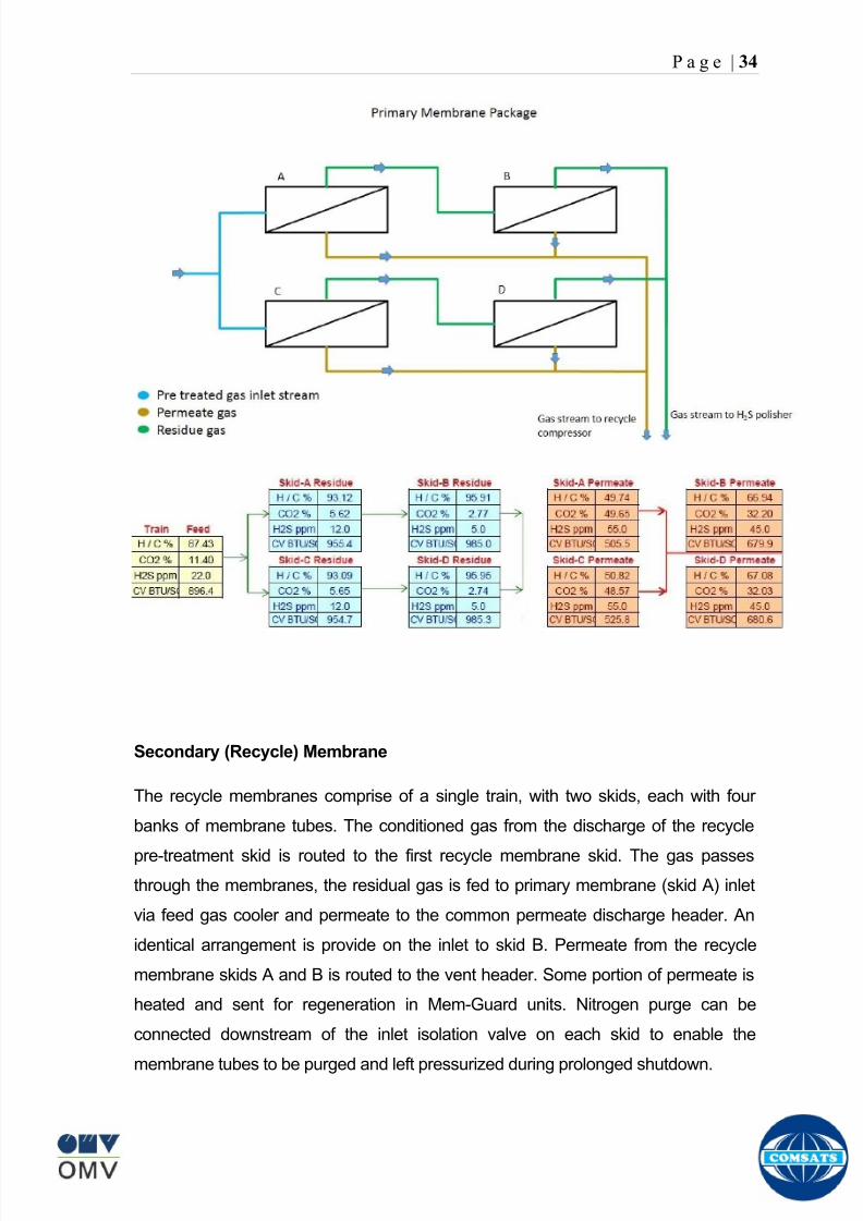
8102019 Gas sweetening Plant
httpslidepdfcomreaderfullgas-sweetening-plant 3862
P a g e | 34
Secondary (Recycle) Membrane
The recycle membranes comprise of a single train with two skids each with four
banks of membrane tubes The conditioned gas from the discharge of the recycle
pre-treatment skid is routed to the first recycle membrane skid The gas passes
through the membranes the residual gas is fed to primary membrane (skid A) inlet
via feed gas cooler and permeate to the common permeate discharge header An
identical arrangement is provide on the inlet to skid B Permeate from the recycle
membrane skids A and B is routed to the vent header Some portion of permeate is
heated and sent for regeneration in Mem-Guard units Nitrogen purge can be
connected downstream of the inlet isolation valve on each skid to enable the
membrane tubes to be purged and left pressurized during prolonged shutdown
8102019 Gas sweetening Plant
httpslidepdfcomreaderfullgas-sweetening-plant 3962
P a g e | 35
Figure Flow Diagram of Recycle membrane unit
8102019 Gas sweetening Plant
httpslidepdfcomreaderfullgas-sweetening-plant 4062
P a g e | 36
ADVANTAGES OF MEMBRANE SYSTEMS
Membrane systems have major advantages over more-traditional methods of
acid gas removal
Lower capital cost Membrane systems are skid mounted and so the
scope cost and time taken for site preparation are minimal Installation
costs are significantly lower than alternative technologies especially for
remote areas Furthermore no additional facilities for solvent storage and
water treatment needed by other processes are required
Lower operating costs The only major operating cost for single-stage
membrane systems is membrane replacement This cost is significantly
lower than the solvent replacement and energy costs associated with
traditional technologies The improvements in membrane and
pretreatment design allow a longer useful membrane life which further
reduces operating costs The energy costs of multistage systems with
large recycle compressors are usually comparable to those for traditionaltechnologies
Deferred capital investment Often contracted sales-gas flow rates
increase over time as more wells are brought on-line With traditional
technologies the system design needs to take this later production into
account immediately and so the majority of the equipment is installed
before it is even needed The modular nature of membrane systems
means that only the membranes that are needed at start-up need be
installed The rest can be added either into existing tubes or in new skids
only when they are required
Operational simplicity and high reliability Because single-stage
membrane systems have no moving parts they have almost no
8102019 Gas sweetening Plant
httpslidepdfcomreaderfullgas-sweetening-plant 4162
P a g e | 37
unscheduled downtime and are extremely simple to operate They can
operate unattended for long periods of time The addition of a recycle
compressor adds some complexity to the system but still much less than
with a solvent- or adsorbent-based technology Multistage systems can be
operated at full capacity as single-stage systems when the recycle
compressor is down
Good weight and space efficiency Skid construction can be optimized
to the space available This space efficiency is especially important for
offshore environments where deck area is at a premium and is the
reason why so many new offshore developments have chosen to use
membranes for acid gas removal Figure 6 illustrates the space efficiency
of membrane systems The membrane unit in the lower left corner
replaced all the amine and glycol plant equipment shown in the rest of the
picture
Adaptability Because membrane area is dictated by the percentage of
acid gas removal rather than absolute acid gas removal small variations
in feed acid gas content hardly change the sales-gas acid gas
specification For example a system designed for 10 down to 3 acid
gas removal produces a 35 product from a 12 feed gas and a 5
product from a 15 feed gas
Design efficiency The membrane and pretreatment systems integrate a
number of operations such as dehydration CO2 and H2S removal dew-
point control and mercury removal Traditional acid gas removal
technologies require all of these operations as separate processes and
may also require additional dehydration because some technologies
saturate the product stream with water
8102019 Gas sweetening Plant
httpslidepdfcomreaderfullgas-sweetening-plant 4262
P a g e | 38
Power generation The permeate gas from membrane systems can be
used to provide fuel gas for power generation either for a recycle
compressor or other equipment
Ideal for debottlenecking Because expanding solvent- or adsorbent-
based acid gas removal plants without adding additional trains is difficult
an ideal solution is to use membranes for bulk acid gas removal and leave
the existing plant for final cleanup An additional advantage is that the
permeate gas from the membrane system can often be used as fuel for
the existing plant thus avoiding significant increase in hydrocarbon
losses
Environmentally friendly Membrane systems do not involve the
periodic removal and handling of spent solvents or adsorbents Permeate
gases can be flared used as fuel or re-injected into the well Items thatdo need disposal such as spent membrane elements can be incinerated
Ideal for remote locations Many of the factors mentioned above make
membrane systems a highly desirable technology for remote locations
where spare parts are rare and labor unskilled Furthermore solvents
storage and trucking water supply power generation or extensive
infrastructure are not required
Re-injection optimizations Since the permeate stream from the
membrane system can be operated at elevated pressures it is possible to
further pressurize by re-injection compression train
8102019 Gas sweetening Plant
httpslidepdfcomreaderfullgas-sweetening-plant 4362
P a g e | 39
Sorption
Sorption is a physical and chemical process by which one substance becomes
attached to another
It is of two main types
1 Absorption
2 Adsorption
Absorption
Absorption is a physical or chemical phenomenon or process in which atoms
molecules or ions enter some bulk phase ndash gas liquid or solid material This is a
different process from adsorption since molecules undergoing absorption are
taken up by the volume not by the surface (as in the case for adsorption)
Absorption process may be chemical (reactive) or physical (non-reactive)
Physical absorption
Physical absorption or non-reactive absorption is made between two phases ofmatter a liquid absorbs a gas or a solid absorbs a liquid
When a liquid solvent absorbs a gas mixture or part of it a mass of gas moves
into the liquid For example water may absorb oxygen from the air This mass
transfer takes place at the interface between the liquid and the gas at a rate
depending on both the gas and the liquid This type of absorption depends on the
solubility of gases the pressure and the temperature The rate and amount of
absorption also depend on the surface area of the interface and its duration in
time
When a solid absorbs a liquid mixture or part of it a mass of liquid moves into the
solid For example a clay pot used to store water may absorb some of the water
This mass transfer takes place at the interface between the solid and the liquid
at a rate depending on both the solid and the liquid
8102019 Gas sweetening Plant
httpslidepdfcomreaderfullgas-sweetening-plant 4462
P a g e | 40
Chemical absorption
Chemical absorption or reactive absorption is a chemical reaction between the
absorbed and the absorbing substances Sometimes it combines with physical
absorption This type of absorption depends upon the stoichiometry of the
reaction and the concentration of its reactants
Adsorption
Adsorption is the adhesion of atoms ions or molecules from a gas liquid or
dissolved solid to a surface This process creates a film of the adsorbate on the
surface of the adsorbent The binding to the surface is usually weak and
reversible Compounds with color and those that have taste or odor tend to bind
strongly Compounds that vibrate at frequencies in the visible spectrum are very
often are strongly adsorbed on activated carbon
The most common industrial adsorbents are activated carbon silica gel and
alumina because they present enormous surface areas per unit weight
Depending on the nature of attractive forces existing between the adsorbate and
adsorbent adsorption can be classified as
i) Physical adsorption
ii) Chemical adsorption
i) Physical adsorption (Physisorption)
In physical adsorption the forces of attraction between the molecules of the
adsorbate and the adsorbent are of the weak van der Waals type Since the
forces of attraction are weak the process of physisorption can be easily reversed
by heating or decreasing the pressure of the adsorbate (as in the case of gases)
8102019 Gas sweetening Plant
httpslidepdfcomreaderfullgas-sweetening-plant 4562
P a g e | 41
ii) Chemical adsorption (Chemisorption)
In chemisorption the forces of attraction between the adsorbate and the
adsorbent are very strong the molecules of adsorbate form chemical bonds with
the molecules of the adsorbent present in the surface
Adsorption is generally accompanied by release of energy that is most
adsorption processes are exothermic in nature Adsorption is a spontaneous
process therefore its free energy change is negative (∆Glt0) However the
entropy change associated with adsorption is generally negative because the
adsorbate molecules lose their translation freedom when they get attached to the
surface of the adsorbent Therefore in order for ∆G to be negative the enthalpy
change (∆H) must be sufficiently negative such that (∆G=∆H-T∆S) lt 0 This
explanation accounts for exothermic adsorption processes In cases where
endothermic adsorption occurs the entropy change ∆S is sufficiently positive
such that ∆G remains negative
Pre treatment
The main function of pretreatment skid is to provide membrane inlet specification
gas as mentioned by the vendor UOP It removes the contaminants that would
poison the membranes like dust solids (adsorbent particles) lube oil heavy
hydrocarbons etc It consists of
Feed Cooler
Feed Gas Scrubber
Filter Coalescer
Feed Gas Heater
Activated Carbon Guard Filter
Particle Filter
8102019 Gas sweetening Plant
httpslidepdfcomreaderfullgas-sweetening-plant 4662
8102019 Gas sweetening Plant
httpslidepdfcomreaderfullgas-sweetening-plant 4762
P a g e | 43
The regeneration is carried out by heated permeate gas from the recycle
membranes at 450oF The vessel is depressurized to 20 psi and heated gas is
introduced from top The gas carries out the adsorbed contaminants and leaves
the vessel from bottom cleaning the adsorbent This contaminated gas is burnt in
the flare
UOP the vendor of Memguard unit has never disclosed that what substance
MG3 and MG5 exactly are But as mentioned by vendor that both care class of
aluminosilicates Therefore MG3 can be potassium aluminosilicate and MG5 can
be Calcium aluminosilicate These are molecular sieves adsorbents Molecular
sieves are a microporous material which can selectively adsorb gases andliquids They are synthetic zeolites (crystalline metal aluminosilicates) which
upon dehydration can efficiently and selectively remove water or other
solvents The selectivity of a molecular sieve is determined by its pore size
molecules with a critical diameter which is less than the pore size will be
efficiently adsorbed while larger molecules will be excluded
8102019 Gas sweetening Plant
httpslidepdfcomreaderfullgas-sweetening-plant 4862
P a g e | 44
3A Molecular Sieve Adsorbent
The 3A molecular sieve adsorbent has a 3 angstrom (3A) pore size which means
that any molecule that is larger than the 3 angstrom pores will not be adsorbed
The 3A molecular sieve is the potassium type of A crystalline structure and is a
form of alkali Aluminosilicate For a 3A molecular sieve the sequence rate that
adsorption occurs is He Ne N and H2O
Due to the crystalline structure molecular sieves that have a 3 angstrom pore
size have a very high rate of adsorption and properties that promote a longer life
for products treated by the sieve The most common use for the 3A molecular
sieve is to remove water and moisture from materials that are in gas and liquid
form
5A Molecular Sieve Adsorbent
These are molecular sieve adsorbents with a pore size of 5 angstrom (5A) 5A
molecular sieves are unable to adsorb any molecules or impurities that are
smaller than 5A It is calcium form of type A crystalline structure and is form of analkali-aluminosilicate that is most commonly used to separate isomerous alkanes
from normal alkanes and to co-adsorb moisture and water along with carbon
dioxide from gases In additional 5A molecular sieves are used for gaseous
pressure swing adsorption (PSA)mdashthat is to separate particular gases from other
gases
Adsorption of nC4H10
Adsorption of nC4H10
Adsorption of C3H8 to C22H46
Adsorption of Freon-12 (dichlorodifluoromethane)
Natural gas drying
Normal- and iso-paraffin separation
Separation of aromatic
8102019 Gas sweetening Plant
httpslidepdfcomreaderfullgas-sweetening-plant 4962
P a g e | 45
Inlet Composition of Memguard vessel
COMPSOSITION MOLE
CARBON DIOXIDE 1096
MEHTANE 8593
ETHANE 173
PROPANE 023
I-BUTANE 008
N BUTANE 004
PENTANES 004
HEXANE + 000
NITROGEN 076
WATER 007
Outlet Composition of Memguard vessel
COMPSOSITION MOLE
CARBON DIOXIDE 1098
MEHTANE 8608
ETHANE 173
PROPANE 023
I-BUTANE 008N BUTANE 004
PENTANES 004
HEXANE + 000
NITROGENT 076
WATER 000
H2S polisher
The H2S polishing unit has been designed to treat 187 MMscfday of natural gas
containing up to 11 CO2 and 21 ppm H2S where the level of the CO2 and H2S
is reduced using a MemGuard Membrane separation unit The unit is situated
down-stream of the membrane unit and will further reduce the level of H2S in the
processed gas to a sales gas specification of 38 ppm
8102019 Gas sweetening Plant
httpslidepdfcomreaderfullgas-sweetening-plant 5062
P a g e | 46
This process uses three non-regenerable fixed bed absorber vessels using a low
temperature high activity absorbent The absorbent is a mixture of activated
metal oxides (mainly zinc oxide) The three towers can are generally operated in
parallel arrangement but on demand can be used in series (any of alternate
arrangements of A B C vessels) as shown in figure
The higher sales gas flow rate increased the catalyst consumption and
replacement frequency
ZnO + H2S =gt ZnS + H20
Routine samples are taken from the beds to provide a check on each bed
performance and to follow the saturation profile during the absorbent life After
the adsorbent has been fully utilized the adsorption vessels are recharged with
new adsorbent discarding the utilized one in a safe manner
109oF
1215 psig
Before H2S Polishing After H2S Polishing
8102019 Gas sweetening Plant
httpslidepdfcomreaderfullgas-sweetening-plant 5162
P a g e | 47
Figure
H2S Tower
Inlet pipe
4 Drums of 19mm
ceramic Balls
6 Micron mesh
5 Drums of 50mmceramic
1 Drums of19mm ceramic
01 Drums of6mm ceramic
112 drums of
Catalist ZnO
8102019 Gas sweetening Plant
httpslidepdfcomreaderfullgas-sweetening-plant 5262
P a g e | 48
Recycle Compressor
The permeate gas of the primary membrane unit carries recoverable amount of
CH4 It is fed to recycle membrane unit for further CH 4 recovery But the
permeate pressure from primary membranes which has been reduced to 12 psi
must be regenerated to 1200 psi for the gas to be fed again to the system For
this purpose we have employed recycle compressor The compressor is a four
stage centrifugal compressor It is driven by gas turbine of 31200 HP It has 25
MW producing capacity
Figure Recycle Compressor Process Flow Diagram
8102019 Gas sweetening Plant
httpslidepdfcomreaderfullgas-sweetening-plant 5362
P a g e | 49
Sales Gas Compressor
Gas from H2S polishing unit is sent to sales gas compressor where its pressure
is enhanced to 1100 psi so it may be injected to SNGPL high pressure trunk line
Sales gas compressor is single stage gas turbine driven
Figure Process Flow of Sales Gas Compressor
8102019 Gas sweetening Plant
httpslidepdfcomreaderfullgas-sweetening-plant 5462
P a g e | 50
Cooling Towers
A cooling tower is a heat rejection device which extracts waste heat to theatmosphere through the cooling of a water stream to a lower temperature Hot
water from the system enters the cooling tower and is distributed over the fill
(heat transfer surface) Air is induced or forced through the fill causing a small
portion of the water to evaporate This evaporation removes heat from the
remaining water which is collected in the cold water basin and returned to the
system to absorb more heat Each cooling tower line although operating under
the same basic principle of operation is arranged a little differently
Types
Natural draft mdash Utilizes buoyancy via a tall chimney Warm moist air naturally
rises due to the density differential compared to the dry cooler outside air Warm
moist air is less dense than drier air at the same pressure This moist air
buoyancy produces an upwards current of air through the tower
Mechanical draft mdash Uses power-driven fan motors to force or draw airthrough the tower
o Induced draft mdash A mechanical draft tower with a fan at the
discharge (at the top) which pulls air up through the tower The fan
induces hot moist air out the discharge This produces low entering
and high exiting air velocities reducing the possibility of
recirculation in which discharged air flows back into the air intake
o Forced draft mdash A mechanical draft tower with a blower type fan at
the intake The fan forces air into the tower creating high entering
and low exiting air velocities The low exiting velocity is much more
susceptible to recirculation This fanfill geometry is also known as
blow-through
8102019 Gas sweetening Plant
httpslidepdfcomreaderfullgas-sweetening-plant 5562
P a g e | 51
Forced Draft Cooling Tower Vs Induced Draft Cooling Tower
Induced Draft Cooling Tower have the ability to handle large water flow
rate than Forced Draft Cooling Tower
Induced Draft Cooling Tower is suitable for large cell sizes and fan sizes
as compared with Forced Draft Larger fan size may result in greater
efficiency and consequently lower power and sound level
Forced Draft Cooling Tower can be square or rectangular type only
however Induced Draft Cooling Towers can be round square or
rectangular type
Induced Draft Cooling Tower uses more compact ground area than Forced
Draft Cooling Tower equivalent capacity due to absence of fan on one
side
Fan equipment is warm exhaust air is less liable to icing up in winter
operation (Cold Countries)
Higher velocity in Forced Draft Cooling Tower cause drop in suspension
and cause additional static resistance to system
Configuration
There are two main configurations of factory assembled cooling towers crossflow
and counterflow In crossflow cooling towers the water flows vertically down the
fill as air flows horizontally across In counterflow cooling towers the water flows
vertically down the fill as air flows vertically up
Crossflow Configuration Counterflow Configuration
8102019 Gas sweetening Plant
httpslidepdfcomreaderfullgas-sweetening-plant 5662
P a g e | 52
Drift mdash Water droplets that are carried out of the cooling tower with the exhaust
air Drift droplets have the same concentration of impurities as the water entering
the tower The drift rate is typically reduced by employing baffle-like devices
called drift eliminators through which the air must travel after leaving the fill and
spray zones of the tower
Blow-out mdash Water droplets blown out of the cooling tower by wind generally at
the air inlet openings Water may also be lost in the absence of wind through
splashing or misting Devices such as wind screens louvers splash deflectors
and water diverters are used to limit these losses
Blow-down mdash The portion of the circulating water flow that is removed (usually
discharged to a drain) in order to maintain the amount of Total Dissolved Solids
(TDS) and other impurities at an acceptably low level Higher TDS concentration
in solution may result from greater cooling tower efficiency However the higher
the TDS concentration the greater the risk of scale biological growth and
corrosion
Make-up mdash The water that must be added to the circulating water system in
order to compensate for water losses such as evaporation drift loss blow-out
blow-down etc
Approach mdash The approach is the difference in temperature between the cooled-
water temperature and the entering-air wet bulb temperature
Range mdash The range is the temperature difference between the warm water inlet
and cooled water exit
Fill mdash Inside the tower fills are added to increase contact surface as well as
contact time between air and water to provide better heat transfer The efficiency
of the tower depends on the selection and amount of fill
8102019 Gas sweetening Plant
httpslidepdfcomreaderfullgas-sweetening-plant 5762
P a g e | 53
There are two types of fills that may be used
o Film type fill (causes water to spread into a thin film)
o Splash type fill (breaks up falling stream of water and interrupts its
vertical progress)
Important
Scale build up is controlled by adding chemicals to the cooling loop and diluting
the concentration by blow down and make-up Following chemicals are added to
the Cooling to control CorrosionSale and microbial growth
Corrosion Inhibitor To control corrosion in the Cooling system
Dispersant To kept ions in suspension to avoid settle down and buildup
Sodium hypo Chlorite To Control microbial Growth
Acid To control Alkalinity in the system
High Stress Polymer To run the system at higher conductivity It is a
multifunctional polymer for Zinc amp Phosphate stabilization in cooling tower
Fin Fan Cooler
Fin fan heat exchanger is simply a pressure vessel which cools a circulating fluid
within finned tubes by forcing ambient air over the exterior of the tubes A
common example of an air cooler is a carrsquos radiator Fin Fan Coolers are used in
any application where large quantities of heat need to be transferred This
includes chemical and petrochemical industries power stations waste-to-energy
facilities as well as steelworks
Fin Fan Cooler are used for two primary reasons
They increase plant efficiency
They are a green solution as compared to cooling towers and shell and
tube heat exchangers because they do not require an auxiliary water
8102019 Gas sweetening Plant
httpslidepdfcomreaderfullgas-sweetening-plant 5862
P a g e | 54
supply (water lost due to drift and evaporation plus no water treatment
chemicals are required)
Figure General Overview of Fin Fan Cooler
Produced Water
The produced water system receives liquid from the equipment Miano slug
catcher train 1 and 2 inlet separators and is fed to three phase separator where
water oil and gas is separated The gases produced are burnt in incinerator
whereas hydrocarbon liquid is stored to be sold Liquid from compressors
recycle inlet separator recycle feed scrubber high and low pressure slug
catchers is passed to degasser Separated water is injected down the earth
Incinerator
The term incinerate means to burn something until nothing is left but ashes An
incinerator is a unit or facility used to burn trash and other types of waste until it is
reduced to ash An incinerator is constructed of heavy well-insulated materials
so that it does not give off extreme amounts of external heat The high levels of
heat are kept inside the furnace or unit so that the waste is burned quickly and
efficiently If the heat were allowed to escape the waste would not burn as
completely or as rapidly
8102019 Gas sweetening Plant
httpslidepdfcomreaderfullgas-sweetening-plant 5962
P a g e | 55
Control System
The plant is controlled at CCR (Central Control Room) by PLCs (Programmable
Logic Controllers) through fiber optic control line All control parameters are
received at LER (Local Equipment Room) via two optic fiber control lines One
being primary and other secondary operating in redundancy ie if primary fails
control shifts to secondary These control parameters are sent to CCR via single
optic fiber cable
Safety System
Wellheads and Gas Processing Plant have their own Fire amp Gas detection
systems emergency shutdown (ESD) Plant has a fault tolerant controller It is
based on Triple Modular Redundant (TMR) architecture manufactured by
Triconex The TMR system is based on three isolated parallel control systems
integrated into one system The system operates on a two out of three voting
principle which provides high integrity error free uninterrupted operation with no
single point of failure The TMR receives inputs from Process Sensors Manual
Switches Fire amp Gas Detectors Packaged Equipment Control Systems and
Product Exporting Facilities The TMR carries out cause and effect processing on
the data received and where necessary produces output signals Outputs from
the TMR are hard wired directly to ESD shutdown and blow down valve
solenoids motor control instrumentelectrical interfaces to control electrical
drives package equipment logic control systems manifold area as well as
telecoms
The operator in central control room is able to accept alarms and once the fault
has been cleared reset the input All the control systems are centralized to a
single interface All the PLCs (Programmable Logic Controllers) communicate with
the servers and servers communicate with the clients through Ethernet connectivity
Centralization eases the navigation of different systems at a common interface
Emergency Shutdown
The ESD system receives inputs from field mounted instrumentation on the process
8102019 Gas sweetening Plant
httpslidepdfcomreaderfullgas-sweetening-plant 6062
P a g e | 56
and utility equipment and initiates executive actions appropriate to the level of ESD
The system is an Active system which is in standby and will activate when in an
alarm or fault condition The Kadanwari Gas Process Facility ESD system is
comprised of five (5) levels The emergency severity decreases with increasing ESD
level number
ESD 1
This shutdown level is automatically initiated by fire major gas leak or a detected
toxic atmosphere in the process area of the plant or manually from CCR A level 1
shutdown will cause all production to cease close all emergency shutdown
valves stop the process and shutdown of the main power generation The
emergency vent valves to the stack will open and in addition all equipment of zone 1
certified will be isolated This is the highest level of ESD and will cause the following
to occur
All Shutdown Valves (SDVs) on the process facility will close All slowdown Valves (BDVs) on the process facility will open
All Main Gas Driven Generators will be tripped
Emergency Diesel Generator will start
All electrical power to process and utility rotating equipment will be
isolated
Wellhead Choke Valves Close Wing Valves Close Upper Master Valve
(UMV) Close
ESD 2
This shutdown level is activated automatically if a major process or utility failure
occurs or manually from CCR All production to the plant from the wellhead is
stopped All emergency shutdown valves trip to their fail safe position
Venting shall be as specified This level of ESD will cause the following to occur
8102019 Gas sweetening Plant
httpslidepdfcomreaderfullgas-sweetening-plant 6162
P a g e | 57
All Shutdown Valves (SDVs) on the process facility will close
All electrical power to process and utility rotating equipment will be
isolated
Wellhead Choke Valve Close Wing Valves Close and Upper Master Valve(UMV) Close
ESD 3
The level 3 shutdown isolates and stops a single process train only Production
continues via the other train This ESD level is initiated by process conditions or
operator at local panel This level of ESD will cause the following to occur
ESD 3A Train 1 production to cease
ESD 3B Train 2 production to cease
All online wellhead choke valves go to minimum flow ie (1O )
ESD 4
A level 4 shutdown shall cease all production from an entire field either
Kadanwari or Miano upstream of the associated slug catchers ESD 4K for
Kadanwari amp ESD 4M for Miano This ESD level is initiated automatically by slug
catcher abnormal process conditions This level of ESD will cause the following
to occur
All SDVs close isolating the relevant slug catcher and its upstream gas
production facility from the Kadanwari Gas Processing Plant
All Wellhead Choke Valves Close Wing Valves Close and Upper MasterValves (UMV) of the relevant gas production facility Close
A parallel timer is provided to close within 10 second if not closed in given
time SSSV seals the well
ESD 5
A level 5 shutdown represents equipment shutdown for the protection of the
individual equipment without any change in the process This level of ESD is for the
protection of various pieces of equipment and is initiated by its own inputs eg
8102019 Gas sweetening Plant
httpslidepdfcomreaderfullgas-sweetening-plant 6262
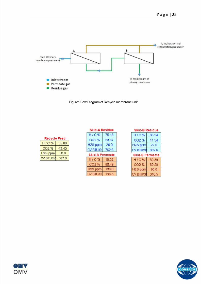
8102019 Gas sweetening Plant
httpslidepdfcomreaderfullgas-sweetening-plant 3962
P a g e | 35
Figure Flow Diagram of Recycle membrane unit
8102019 Gas sweetening Plant
httpslidepdfcomreaderfullgas-sweetening-plant 4062
P a g e | 36
ADVANTAGES OF MEMBRANE SYSTEMS
Membrane systems have major advantages over more-traditional methods of
acid gas removal
Lower capital cost Membrane systems are skid mounted and so the
scope cost and time taken for site preparation are minimal Installation
costs are significantly lower than alternative technologies especially for
remote areas Furthermore no additional facilities for solvent storage and
water treatment needed by other processes are required
Lower operating costs The only major operating cost for single-stage
membrane systems is membrane replacement This cost is significantly
lower than the solvent replacement and energy costs associated with
traditional technologies The improvements in membrane and
pretreatment design allow a longer useful membrane life which further
reduces operating costs The energy costs of multistage systems with
large recycle compressors are usually comparable to those for traditionaltechnologies
Deferred capital investment Often contracted sales-gas flow rates
increase over time as more wells are brought on-line With traditional
technologies the system design needs to take this later production into
account immediately and so the majority of the equipment is installed
before it is even needed The modular nature of membrane systems
means that only the membranes that are needed at start-up need be
installed The rest can be added either into existing tubes or in new skids
only when they are required
Operational simplicity and high reliability Because single-stage
membrane systems have no moving parts they have almost no
8102019 Gas sweetening Plant
httpslidepdfcomreaderfullgas-sweetening-plant 4162
P a g e | 37
unscheduled downtime and are extremely simple to operate They can
operate unattended for long periods of time The addition of a recycle
compressor adds some complexity to the system but still much less than
with a solvent- or adsorbent-based technology Multistage systems can be
operated at full capacity as single-stage systems when the recycle
compressor is down
Good weight and space efficiency Skid construction can be optimized
to the space available This space efficiency is especially important for
offshore environments where deck area is at a premium and is the
reason why so many new offshore developments have chosen to use
membranes for acid gas removal Figure 6 illustrates the space efficiency
of membrane systems The membrane unit in the lower left corner
replaced all the amine and glycol plant equipment shown in the rest of the
picture
Adaptability Because membrane area is dictated by the percentage of
acid gas removal rather than absolute acid gas removal small variations
in feed acid gas content hardly change the sales-gas acid gas
specification For example a system designed for 10 down to 3 acid
gas removal produces a 35 product from a 12 feed gas and a 5
product from a 15 feed gas
Design efficiency The membrane and pretreatment systems integrate a
number of operations such as dehydration CO2 and H2S removal dew-
point control and mercury removal Traditional acid gas removal
technologies require all of these operations as separate processes and
may also require additional dehydration because some technologies
saturate the product stream with water
8102019 Gas sweetening Plant
httpslidepdfcomreaderfullgas-sweetening-plant 4262
P a g e | 38
Power generation The permeate gas from membrane systems can be
used to provide fuel gas for power generation either for a recycle
compressor or other equipment
Ideal for debottlenecking Because expanding solvent- or adsorbent-
based acid gas removal plants without adding additional trains is difficult
an ideal solution is to use membranes for bulk acid gas removal and leave
the existing plant for final cleanup An additional advantage is that the
permeate gas from the membrane system can often be used as fuel for
the existing plant thus avoiding significant increase in hydrocarbon
losses
Environmentally friendly Membrane systems do not involve the
periodic removal and handling of spent solvents or adsorbents Permeate
gases can be flared used as fuel or re-injected into the well Items thatdo need disposal such as spent membrane elements can be incinerated
Ideal for remote locations Many of the factors mentioned above make
membrane systems a highly desirable technology for remote locations
where spare parts are rare and labor unskilled Furthermore solvents
storage and trucking water supply power generation or extensive
infrastructure are not required
Re-injection optimizations Since the permeate stream from the
membrane system can be operated at elevated pressures it is possible to
further pressurize by re-injection compression train
8102019 Gas sweetening Plant
httpslidepdfcomreaderfullgas-sweetening-plant 4362
P a g e | 39
Sorption
Sorption is a physical and chemical process by which one substance becomes
attached to another
It is of two main types
1 Absorption
2 Adsorption
Absorption
Absorption is a physical or chemical phenomenon or process in which atoms
molecules or ions enter some bulk phase ndash gas liquid or solid material This is a
different process from adsorption since molecules undergoing absorption are
taken up by the volume not by the surface (as in the case for adsorption)
Absorption process may be chemical (reactive) or physical (non-reactive)
Physical absorption
Physical absorption or non-reactive absorption is made between two phases ofmatter a liquid absorbs a gas or a solid absorbs a liquid
When a liquid solvent absorbs a gas mixture or part of it a mass of gas moves
into the liquid For example water may absorb oxygen from the air This mass
transfer takes place at the interface between the liquid and the gas at a rate
depending on both the gas and the liquid This type of absorption depends on the
solubility of gases the pressure and the temperature The rate and amount of
absorption also depend on the surface area of the interface and its duration in
time
When a solid absorbs a liquid mixture or part of it a mass of liquid moves into the
solid For example a clay pot used to store water may absorb some of the water
This mass transfer takes place at the interface between the solid and the liquid
at a rate depending on both the solid and the liquid
8102019 Gas sweetening Plant
httpslidepdfcomreaderfullgas-sweetening-plant 4462
P a g e | 40
Chemical absorption
Chemical absorption or reactive absorption is a chemical reaction between the
absorbed and the absorbing substances Sometimes it combines with physical
absorption This type of absorption depends upon the stoichiometry of the
reaction and the concentration of its reactants
Adsorption
Adsorption is the adhesion of atoms ions or molecules from a gas liquid or
dissolved solid to a surface This process creates a film of the adsorbate on the
surface of the adsorbent The binding to the surface is usually weak and
reversible Compounds with color and those that have taste or odor tend to bind
strongly Compounds that vibrate at frequencies in the visible spectrum are very
often are strongly adsorbed on activated carbon
The most common industrial adsorbents are activated carbon silica gel and
alumina because they present enormous surface areas per unit weight
Depending on the nature of attractive forces existing between the adsorbate and
adsorbent adsorption can be classified as
i) Physical adsorption
ii) Chemical adsorption
i) Physical adsorption (Physisorption)
In physical adsorption the forces of attraction between the molecules of the
adsorbate and the adsorbent are of the weak van der Waals type Since the
forces of attraction are weak the process of physisorption can be easily reversed
by heating or decreasing the pressure of the adsorbate (as in the case of gases)
8102019 Gas sweetening Plant
httpslidepdfcomreaderfullgas-sweetening-plant 4562
P a g e | 41
ii) Chemical adsorption (Chemisorption)
In chemisorption the forces of attraction between the adsorbate and the
adsorbent are very strong the molecules of adsorbate form chemical bonds with
the molecules of the adsorbent present in the surface
Adsorption is generally accompanied by release of energy that is most
adsorption processes are exothermic in nature Adsorption is a spontaneous
process therefore its free energy change is negative (∆Glt0) However the
entropy change associated with adsorption is generally negative because the
adsorbate molecules lose their translation freedom when they get attached to the
surface of the adsorbent Therefore in order for ∆G to be negative the enthalpy
change (∆H) must be sufficiently negative such that (∆G=∆H-T∆S) lt 0 This
explanation accounts for exothermic adsorption processes In cases where
endothermic adsorption occurs the entropy change ∆S is sufficiently positive
such that ∆G remains negative
Pre treatment
The main function of pretreatment skid is to provide membrane inlet specification
gas as mentioned by the vendor UOP It removes the contaminants that would
poison the membranes like dust solids (adsorbent particles) lube oil heavy
hydrocarbons etc It consists of
Feed Cooler
Feed Gas Scrubber
Filter Coalescer
Feed Gas Heater
Activated Carbon Guard Filter
Particle Filter
8102019 Gas sweetening Plant
httpslidepdfcomreaderfullgas-sweetening-plant 4662
8102019 Gas sweetening Plant
httpslidepdfcomreaderfullgas-sweetening-plant 4762
P a g e | 43
The regeneration is carried out by heated permeate gas from the recycle
membranes at 450oF The vessel is depressurized to 20 psi and heated gas is
introduced from top The gas carries out the adsorbed contaminants and leaves
the vessel from bottom cleaning the adsorbent This contaminated gas is burnt in
the flare
UOP the vendor of Memguard unit has never disclosed that what substance
MG3 and MG5 exactly are But as mentioned by vendor that both care class of
aluminosilicates Therefore MG3 can be potassium aluminosilicate and MG5 can
be Calcium aluminosilicate These are molecular sieves adsorbents Molecular
sieves are a microporous material which can selectively adsorb gases andliquids They are synthetic zeolites (crystalline metal aluminosilicates) which
upon dehydration can efficiently and selectively remove water or other
solvents The selectivity of a molecular sieve is determined by its pore size
molecules with a critical diameter which is less than the pore size will be
efficiently adsorbed while larger molecules will be excluded
8102019 Gas sweetening Plant
httpslidepdfcomreaderfullgas-sweetening-plant 4862
P a g e | 44
3A Molecular Sieve Adsorbent
The 3A molecular sieve adsorbent has a 3 angstrom (3A) pore size which means
that any molecule that is larger than the 3 angstrom pores will not be adsorbed
The 3A molecular sieve is the potassium type of A crystalline structure and is a
form of alkali Aluminosilicate For a 3A molecular sieve the sequence rate that
adsorption occurs is He Ne N and H2O
Due to the crystalline structure molecular sieves that have a 3 angstrom pore
size have a very high rate of adsorption and properties that promote a longer life
for products treated by the sieve The most common use for the 3A molecular
sieve is to remove water and moisture from materials that are in gas and liquid
form
5A Molecular Sieve Adsorbent
These are molecular sieve adsorbents with a pore size of 5 angstrom (5A) 5A
molecular sieves are unable to adsorb any molecules or impurities that are
smaller than 5A It is calcium form of type A crystalline structure and is form of analkali-aluminosilicate that is most commonly used to separate isomerous alkanes
from normal alkanes and to co-adsorb moisture and water along with carbon
dioxide from gases In additional 5A molecular sieves are used for gaseous
pressure swing adsorption (PSA)mdashthat is to separate particular gases from other
gases
Adsorption of nC4H10
Adsorption of nC4H10
Adsorption of C3H8 to C22H46
Adsorption of Freon-12 (dichlorodifluoromethane)
Natural gas drying
Normal- and iso-paraffin separation
Separation of aromatic
8102019 Gas sweetening Plant
httpslidepdfcomreaderfullgas-sweetening-plant 4962
P a g e | 45
Inlet Composition of Memguard vessel
COMPSOSITION MOLE
CARBON DIOXIDE 1096
MEHTANE 8593
ETHANE 173
PROPANE 023
I-BUTANE 008
N BUTANE 004
PENTANES 004
HEXANE + 000
NITROGEN 076
WATER 007
Outlet Composition of Memguard vessel
COMPSOSITION MOLE
CARBON DIOXIDE 1098
MEHTANE 8608
ETHANE 173
PROPANE 023
I-BUTANE 008N BUTANE 004
PENTANES 004
HEXANE + 000
NITROGENT 076
WATER 000
H2S polisher
The H2S polishing unit has been designed to treat 187 MMscfday of natural gas
containing up to 11 CO2 and 21 ppm H2S where the level of the CO2 and H2S
is reduced using a MemGuard Membrane separation unit The unit is situated
down-stream of the membrane unit and will further reduce the level of H2S in the
processed gas to a sales gas specification of 38 ppm
8102019 Gas sweetening Plant
httpslidepdfcomreaderfullgas-sweetening-plant 5062
P a g e | 46
This process uses three non-regenerable fixed bed absorber vessels using a low
temperature high activity absorbent The absorbent is a mixture of activated
metal oxides (mainly zinc oxide) The three towers can are generally operated in
parallel arrangement but on demand can be used in series (any of alternate
arrangements of A B C vessels) as shown in figure
The higher sales gas flow rate increased the catalyst consumption and
replacement frequency
ZnO + H2S =gt ZnS + H20
Routine samples are taken from the beds to provide a check on each bed
performance and to follow the saturation profile during the absorbent life After
the adsorbent has been fully utilized the adsorption vessels are recharged with
new adsorbent discarding the utilized one in a safe manner
109oF
1215 psig
Before H2S Polishing After H2S Polishing
8102019 Gas sweetening Plant
httpslidepdfcomreaderfullgas-sweetening-plant 5162
P a g e | 47
Figure
H2S Tower
Inlet pipe
4 Drums of 19mm
ceramic Balls
6 Micron mesh
5 Drums of 50mmceramic
1 Drums of19mm ceramic
01 Drums of6mm ceramic
112 drums of
Catalist ZnO
8102019 Gas sweetening Plant
httpslidepdfcomreaderfullgas-sweetening-plant 5262
P a g e | 48
Recycle Compressor
The permeate gas of the primary membrane unit carries recoverable amount of
CH4 It is fed to recycle membrane unit for further CH 4 recovery But the
permeate pressure from primary membranes which has been reduced to 12 psi
must be regenerated to 1200 psi for the gas to be fed again to the system For
this purpose we have employed recycle compressor The compressor is a four
stage centrifugal compressor It is driven by gas turbine of 31200 HP It has 25
MW producing capacity
Figure Recycle Compressor Process Flow Diagram
8102019 Gas sweetening Plant
httpslidepdfcomreaderfullgas-sweetening-plant 5362
P a g e | 49
Sales Gas Compressor
Gas from H2S polishing unit is sent to sales gas compressor where its pressure
is enhanced to 1100 psi so it may be injected to SNGPL high pressure trunk line
Sales gas compressor is single stage gas turbine driven
Figure Process Flow of Sales Gas Compressor
8102019 Gas sweetening Plant
httpslidepdfcomreaderfullgas-sweetening-plant 5462
P a g e | 50
Cooling Towers
A cooling tower is a heat rejection device which extracts waste heat to theatmosphere through the cooling of a water stream to a lower temperature Hot
water from the system enters the cooling tower and is distributed over the fill
(heat transfer surface) Air is induced or forced through the fill causing a small
portion of the water to evaporate This evaporation removes heat from the
remaining water which is collected in the cold water basin and returned to the
system to absorb more heat Each cooling tower line although operating under
the same basic principle of operation is arranged a little differently
Types
Natural draft mdash Utilizes buoyancy via a tall chimney Warm moist air naturally
rises due to the density differential compared to the dry cooler outside air Warm
moist air is less dense than drier air at the same pressure This moist air
buoyancy produces an upwards current of air through the tower
Mechanical draft mdash Uses power-driven fan motors to force or draw airthrough the tower
o Induced draft mdash A mechanical draft tower with a fan at the
discharge (at the top) which pulls air up through the tower The fan
induces hot moist air out the discharge This produces low entering
and high exiting air velocities reducing the possibility of
recirculation in which discharged air flows back into the air intake
o Forced draft mdash A mechanical draft tower with a blower type fan at
the intake The fan forces air into the tower creating high entering
and low exiting air velocities The low exiting velocity is much more
susceptible to recirculation This fanfill geometry is also known as
blow-through
8102019 Gas sweetening Plant
httpslidepdfcomreaderfullgas-sweetening-plant 5562
P a g e | 51
Forced Draft Cooling Tower Vs Induced Draft Cooling Tower
Induced Draft Cooling Tower have the ability to handle large water flow
rate than Forced Draft Cooling Tower
Induced Draft Cooling Tower is suitable for large cell sizes and fan sizes
as compared with Forced Draft Larger fan size may result in greater
efficiency and consequently lower power and sound level
Forced Draft Cooling Tower can be square or rectangular type only
however Induced Draft Cooling Towers can be round square or
rectangular type
Induced Draft Cooling Tower uses more compact ground area than Forced
Draft Cooling Tower equivalent capacity due to absence of fan on one
side
Fan equipment is warm exhaust air is less liable to icing up in winter
operation (Cold Countries)
Higher velocity in Forced Draft Cooling Tower cause drop in suspension
and cause additional static resistance to system
Configuration
There are two main configurations of factory assembled cooling towers crossflow
and counterflow In crossflow cooling towers the water flows vertically down the
fill as air flows horizontally across In counterflow cooling towers the water flows
vertically down the fill as air flows vertically up
Crossflow Configuration Counterflow Configuration
8102019 Gas sweetening Plant
httpslidepdfcomreaderfullgas-sweetening-plant 5662
P a g e | 52
Drift mdash Water droplets that are carried out of the cooling tower with the exhaust
air Drift droplets have the same concentration of impurities as the water entering
the tower The drift rate is typically reduced by employing baffle-like devices
called drift eliminators through which the air must travel after leaving the fill and
spray zones of the tower
Blow-out mdash Water droplets blown out of the cooling tower by wind generally at
the air inlet openings Water may also be lost in the absence of wind through
splashing or misting Devices such as wind screens louvers splash deflectors
and water diverters are used to limit these losses
Blow-down mdash The portion of the circulating water flow that is removed (usually
discharged to a drain) in order to maintain the amount of Total Dissolved Solids
(TDS) and other impurities at an acceptably low level Higher TDS concentration
in solution may result from greater cooling tower efficiency However the higher
the TDS concentration the greater the risk of scale biological growth and
corrosion
Make-up mdash The water that must be added to the circulating water system in
order to compensate for water losses such as evaporation drift loss blow-out
blow-down etc
Approach mdash The approach is the difference in temperature between the cooled-
water temperature and the entering-air wet bulb temperature
Range mdash The range is the temperature difference between the warm water inlet
and cooled water exit
Fill mdash Inside the tower fills are added to increase contact surface as well as
contact time between air and water to provide better heat transfer The efficiency
of the tower depends on the selection and amount of fill
8102019 Gas sweetening Plant
httpslidepdfcomreaderfullgas-sweetening-plant 5762
P a g e | 53
There are two types of fills that may be used
o Film type fill (causes water to spread into a thin film)
o Splash type fill (breaks up falling stream of water and interrupts its
vertical progress)
Important
Scale build up is controlled by adding chemicals to the cooling loop and diluting
the concentration by blow down and make-up Following chemicals are added to
the Cooling to control CorrosionSale and microbial growth
Corrosion Inhibitor To control corrosion in the Cooling system
Dispersant To kept ions in suspension to avoid settle down and buildup
Sodium hypo Chlorite To Control microbial Growth
Acid To control Alkalinity in the system
High Stress Polymer To run the system at higher conductivity It is a
multifunctional polymer for Zinc amp Phosphate stabilization in cooling tower
Fin Fan Cooler
Fin fan heat exchanger is simply a pressure vessel which cools a circulating fluid
within finned tubes by forcing ambient air over the exterior of the tubes A
common example of an air cooler is a carrsquos radiator Fin Fan Coolers are used in
any application where large quantities of heat need to be transferred This
includes chemical and petrochemical industries power stations waste-to-energy
facilities as well as steelworks
Fin Fan Cooler are used for two primary reasons
They increase plant efficiency
They are a green solution as compared to cooling towers and shell and
tube heat exchangers because they do not require an auxiliary water
8102019 Gas sweetening Plant
httpslidepdfcomreaderfullgas-sweetening-plant 5862
P a g e | 54
supply (water lost due to drift and evaporation plus no water treatment
chemicals are required)
Figure General Overview of Fin Fan Cooler
Produced Water
The produced water system receives liquid from the equipment Miano slug
catcher train 1 and 2 inlet separators and is fed to three phase separator where
water oil and gas is separated The gases produced are burnt in incinerator
whereas hydrocarbon liquid is stored to be sold Liquid from compressors
recycle inlet separator recycle feed scrubber high and low pressure slug
catchers is passed to degasser Separated water is injected down the earth
Incinerator
The term incinerate means to burn something until nothing is left but ashes An
incinerator is a unit or facility used to burn trash and other types of waste until it is
reduced to ash An incinerator is constructed of heavy well-insulated materials
so that it does not give off extreme amounts of external heat The high levels of
heat are kept inside the furnace or unit so that the waste is burned quickly and
efficiently If the heat were allowed to escape the waste would not burn as
completely or as rapidly
8102019 Gas sweetening Plant
httpslidepdfcomreaderfullgas-sweetening-plant 5962
P a g e | 55
Control System
The plant is controlled at CCR (Central Control Room) by PLCs (Programmable
Logic Controllers) through fiber optic control line All control parameters are
received at LER (Local Equipment Room) via two optic fiber control lines One
being primary and other secondary operating in redundancy ie if primary fails
control shifts to secondary These control parameters are sent to CCR via single
optic fiber cable
Safety System
Wellheads and Gas Processing Plant have their own Fire amp Gas detection
systems emergency shutdown (ESD) Plant has a fault tolerant controller It is
based on Triple Modular Redundant (TMR) architecture manufactured by
Triconex The TMR system is based on three isolated parallel control systems
integrated into one system The system operates on a two out of three voting
principle which provides high integrity error free uninterrupted operation with no
single point of failure The TMR receives inputs from Process Sensors Manual
Switches Fire amp Gas Detectors Packaged Equipment Control Systems and
Product Exporting Facilities The TMR carries out cause and effect processing on
the data received and where necessary produces output signals Outputs from
the TMR are hard wired directly to ESD shutdown and blow down valve
solenoids motor control instrumentelectrical interfaces to control electrical
drives package equipment logic control systems manifold area as well as
telecoms
The operator in central control room is able to accept alarms and once the fault
has been cleared reset the input All the control systems are centralized to a
single interface All the PLCs (Programmable Logic Controllers) communicate with
the servers and servers communicate with the clients through Ethernet connectivity
Centralization eases the navigation of different systems at a common interface
Emergency Shutdown
The ESD system receives inputs from field mounted instrumentation on the process
8102019 Gas sweetening Plant
httpslidepdfcomreaderfullgas-sweetening-plant 6062
P a g e | 56
and utility equipment and initiates executive actions appropriate to the level of ESD
The system is an Active system which is in standby and will activate when in an
alarm or fault condition The Kadanwari Gas Process Facility ESD system is
comprised of five (5) levels The emergency severity decreases with increasing ESD
level number
ESD 1
This shutdown level is automatically initiated by fire major gas leak or a detected
toxic atmosphere in the process area of the plant or manually from CCR A level 1
shutdown will cause all production to cease close all emergency shutdown
valves stop the process and shutdown of the main power generation The
emergency vent valves to the stack will open and in addition all equipment of zone 1
certified will be isolated This is the highest level of ESD and will cause the following
to occur
All Shutdown Valves (SDVs) on the process facility will close All slowdown Valves (BDVs) on the process facility will open
All Main Gas Driven Generators will be tripped
Emergency Diesel Generator will start
All electrical power to process and utility rotating equipment will be
isolated
Wellhead Choke Valves Close Wing Valves Close Upper Master Valve
(UMV) Close
ESD 2
This shutdown level is activated automatically if a major process or utility failure
occurs or manually from CCR All production to the plant from the wellhead is
stopped All emergency shutdown valves trip to their fail safe position
Venting shall be as specified This level of ESD will cause the following to occur
8102019 Gas sweetening Plant
httpslidepdfcomreaderfullgas-sweetening-plant 6162
P a g e | 57
All Shutdown Valves (SDVs) on the process facility will close
All electrical power to process and utility rotating equipment will be
isolated
Wellhead Choke Valve Close Wing Valves Close and Upper Master Valve(UMV) Close
ESD 3
The level 3 shutdown isolates and stops a single process train only Production
continues via the other train This ESD level is initiated by process conditions or
operator at local panel This level of ESD will cause the following to occur
ESD 3A Train 1 production to cease
ESD 3B Train 2 production to cease
All online wellhead choke valves go to minimum flow ie (1O )
ESD 4
A level 4 shutdown shall cease all production from an entire field either
Kadanwari or Miano upstream of the associated slug catchers ESD 4K for
Kadanwari amp ESD 4M for Miano This ESD level is initiated automatically by slug
catcher abnormal process conditions This level of ESD will cause the following
to occur
All SDVs close isolating the relevant slug catcher and its upstream gas
production facility from the Kadanwari Gas Processing Plant
All Wellhead Choke Valves Close Wing Valves Close and Upper MasterValves (UMV) of the relevant gas production facility Close
A parallel timer is provided to close within 10 second if not closed in given
time SSSV seals the well
ESD 5
A level 5 shutdown represents equipment shutdown for the protection of the
individual equipment without any change in the process This level of ESD is for the
protection of various pieces of equipment and is initiated by its own inputs eg
8102019 Gas sweetening Plant
httpslidepdfcomreaderfullgas-sweetening-plant 6262
8102019 Gas sweetening Plant
httpslidepdfcomreaderfullgas-sweetening-plant 4662
8102019 Gas sweetening Plant
httpslidepdfcomreaderfullgas-sweetening-plant 4762
P a g e | 43
The regeneration is carried out by heated permeate gas from the recycle
membranes at 450oF The vessel is depressurized to 20 psi and heated gas is
introduced from top The gas carries out the adsorbed contaminants and leaves
the vessel from bottom cleaning the adsorbent This contaminated gas is burnt in
the flare
UOP the vendor of Memguard unit has never disclosed that what substance
MG3 and MG5 exactly are But as mentioned by vendor that both care class of
aluminosilicates Therefore MG3 can be potassium aluminosilicate and MG5 can
be Calcium aluminosilicate These are molecular sieves adsorbents Molecular
sieves are a microporous material which can selectively adsorb gases andliquids They are synthetic zeolites (crystalline metal aluminosilicates) which
upon dehydration can efficiently and selectively remove water or other
solvents The selectivity of a molecular sieve is determined by its pore size
molecules with a critical diameter which is less than the pore size will be
efficiently adsorbed while larger molecules will be excluded
8102019 Gas sweetening Plant
httpslidepdfcomreaderfullgas-sweetening-plant 4862
P a g e | 44
3A Molecular Sieve Adsorbent
The 3A molecular sieve adsorbent has a 3 angstrom (3A) pore size which means
that any molecule that is larger than the 3 angstrom pores will not be adsorbed
The 3A molecular sieve is the potassium type of A crystalline structure and is a
form of alkali Aluminosilicate For a 3A molecular sieve the sequence rate that
adsorption occurs is He Ne N and H2O
Due to the crystalline structure molecular sieves that have a 3 angstrom pore
size have a very high rate of adsorption and properties that promote a longer life
for products treated by the sieve The most common use for the 3A molecular
sieve is to remove water and moisture from materials that are in gas and liquid
form
5A Molecular Sieve Adsorbent
These are molecular sieve adsorbents with a pore size of 5 angstrom (5A) 5A
molecular sieves are unable to adsorb any molecules or impurities that are
smaller than 5A It is calcium form of type A crystalline structure and is form of analkali-aluminosilicate that is most commonly used to separate isomerous alkanes
from normal alkanes and to co-adsorb moisture and water along with carbon
dioxide from gases In additional 5A molecular sieves are used for gaseous
pressure swing adsorption (PSA)mdashthat is to separate particular gases from other
gases
Adsorption of nC4H10
Adsorption of nC4H10
Adsorption of C3H8 to C22H46
Adsorption of Freon-12 (dichlorodifluoromethane)
Natural gas drying
Normal- and iso-paraffin separation
Separation of aromatic
8102019 Gas sweetening Plant
httpslidepdfcomreaderfullgas-sweetening-plant 4962
P a g e | 45
Inlet Composition of Memguard vessel
COMPSOSITION MOLE
CARBON DIOXIDE 1096
MEHTANE 8593
ETHANE 173
PROPANE 023
I-BUTANE 008
N BUTANE 004
PENTANES 004
HEXANE + 000
NITROGEN 076
WATER 007
Outlet Composition of Memguard vessel
COMPSOSITION MOLE
CARBON DIOXIDE 1098
MEHTANE 8608
ETHANE 173
PROPANE 023
I-BUTANE 008N BUTANE 004
PENTANES 004
HEXANE + 000
NITROGENT 076
WATER 000
H2S polisher
The H2S polishing unit has been designed to treat 187 MMscfday of natural gas
containing up to 11 CO2 and 21 ppm H2S where the level of the CO2 and H2S
is reduced using a MemGuard Membrane separation unit The unit is situated
down-stream of the membrane unit and will further reduce the level of H2S in the
processed gas to a sales gas specification of 38 ppm
8102019 Gas sweetening Plant
httpslidepdfcomreaderfullgas-sweetening-plant 5062
P a g e | 46
This process uses three non-regenerable fixed bed absorber vessels using a low
temperature high activity absorbent The absorbent is a mixture of activated
metal oxides (mainly zinc oxide) The three towers can are generally operated in
parallel arrangement but on demand can be used in series (any of alternate
arrangements of A B C vessels) as shown in figure
The higher sales gas flow rate increased the catalyst consumption and
replacement frequency
ZnO + H2S =gt ZnS + H20
Routine samples are taken from the beds to provide a check on each bed
performance and to follow the saturation profile during the absorbent life After
the adsorbent has been fully utilized the adsorption vessels are recharged with
new adsorbent discarding the utilized one in a safe manner
109oF
1215 psig
Before H2S Polishing After H2S Polishing
8102019 Gas sweetening Plant
httpslidepdfcomreaderfullgas-sweetening-plant 5162
P a g e | 47
Figure
H2S Tower
Inlet pipe
4 Drums of 19mm
ceramic Balls
6 Micron mesh
5 Drums of 50mmceramic
1 Drums of19mm ceramic
01 Drums of6mm ceramic
112 drums of
Catalist ZnO
8102019 Gas sweetening Plant
httpslidepdfcomreaderfullgas-sweetening-plant 5262
P a g e | 48
Recycle Compressor
The permeate gas of the primary membrane unit carries recoverable amount of
CH4 It is fed to recycle membrane unit for further CH 4 recovery But the
permeate pressure from primary membranes which has been reduced to 12 psi
must be regenerated to 1200 psi for the gas to be fed again to the system For
this purpose we have employed recycle compressor The compressor is a four
stage centrifugal compressor It is driven by gas turbine of 31200 HP It has 25
MW producing capacity
Figure Recycle Compressor Process Flow Diagram
8102019 Gas sweetening Plant
httpslidepdfcomreaderfullgas-sweetening-plant 5362
P a g e | 49
Sales Gas Compressor
Gas from H2S polishing unit is sent to sales gas compressor where its pressure
is enhanced to 1100 psi so it may be injected to SNGPL high pressure trunk line
Sales gas compressor is single stage gas turbine driven
Figure Process Flow of Sales Gas Compressor
8102019 Gas sweetening Plant
httpslidepdfcomreaderfullgas-sweetening-plant 5462
P a g e | 50
Cooling Towers
A cooling tower is a heat rejection device which extracts waste heat to theatmosphere through the cooling of a water stream to a lower temperature Hot
water from the system enters the cooling tower and is distributed over the fill
(heat transfer surface) Air is induced or forced through the fill causing a small
portion of the water to evaporate This evaporation removes heat from the
remaining water which is collected in the cold water basin and returned to the
system to absorb more heat Each cooling tower line although operating under
the same basic principle of operation is arranged a little differently
Types
Natural draft mdash Utilizes buoyancy via a tall chimney Warm moist air naturally
rises due to the density differential compared to the dry cooler outside air Warm
moist air is less dense than drier air at the same pressure This moist air
buoyancy produces an upwards current of air through the tower
Mechanical draft mdash Uses power-driven fan motors to force or draw airthrough the tower
o Induced draft mdash A mechanical draft tower with a fan at the
discharge (at the top) which pulls air up through the tower The fan
induces hot moist air out the discharge This produces low entering
and high exiting air velocities reducing the possibility of
recirculation in which discharged air flows back into the air intake
o Forced draft mdash A mechanical draft tower with a blower type fan at
the intake The fan forces air into the tower creating high entering
and low exiting air velocities The low exiting velocity is much more
susceptible to recirculation This fanfill geometry is also known as
blow-through
8102019 Gas sweetening Plant
httpslidepdfcomreaderfullgas-sweetening-plant 5562
P a g e | 51
Forced Draft Cooling Tower Vs Induced Draft Cooling Tower
Induced Draft Cooling Tower have the ability to handle large water flow
rate than Forced Draft Cooling Tower
Induced Draft Cooling Tower is suitable for large cell sizes and fan sizes
as compared with Forced Draft Larger fan size may result in greater
efficiency and consequently lower power and sound level
Forced Draft Cooling Tower can be square or rectangular type only
however Induced Draft Cooling Towers can be round square or
rectangular type
Induced Draft Cooling Tower uses more compact ground area than Forced
Draft Cooling Tower equivalent capacity due to absence of fan on one
side
Fan equipment is warm exhaust air is less liable to icing up in winter
operation (Cold Countries)
Higher velocity in Forced Draft Cooling Tower cause drop in suspension
and cause additional static resistance to system
Configuration
There are two main configurations of factory assembled cooling towers crossflow
and counterflow In crossflow cooling towers the water flows vertically down the
fill as air flows horizontally across In counterflow cooling towers the water flows
vertically down the fill as air flows vertically up
Crossflow Configuration Counterflow Configuration
8102019 Gas sweetening Plant
httpslidepdfcomreaderfullgas-sweetening-plant 5662
P a g e | 52
Drift mdash Water droplets that are carried out of the cooling tower with the exhaust
air Drift droplets have the same concentration of impurities as the water entering
the tower The drift rate is typically reduced by employing baffle-like devices
called drift eliminators through which the air must travel after leaving the fill and
spray zones of the tower
Blow-out mdash Water droplets blown out of the cooling tower by wind generally at
the air inlet openings Water may also be lost in the absence of wind through
splashing or misting Devices such as wind screens louvers splash deflectors
and water diverters are used to limit these losses
Blow-down mdash The portion of the circulating water flow that is removed (usually
discharged to a drain) in order to maintain the amount of Total Dissolved Solids
(TDS) and other impurities at an acceptably low level Higher TDS concentration
in solution may result from greater cooling tower efficiency However the higher
the TDS concentration the greater the risk of scale biological growth and
corrosion
Make-up mdash The water that must be added to the circulating water system in
order to compensate for water losses such as evaporation drift loss blow-out
blow-down etc
Approach mdash The approach is the difference in temperature between the cooled-
water temperature and the entering-air wet bulb temperature
Range mdash The range is the temperature difference between the warm water inlet
and cooled water exit
Fill mdash Inside the tower fills are added to increase contact surface as well as
contact time between air and water to provide better heat transfer The efficiency
of the tower depends on the selection and amount of fill
8102019 Gas sweetening Plant
httpslidepdfcomreaderfullgas-sweetening-plant 5762
P a g e | 53
There are two types of fills that may be used
o Film type fill (causes water to spread into a thin film)
o Splash type fill (breaks up falling stream of water and interrupts its
vertical progress)
Important
Scale build up is controlled by adding chemicals to the cooling loop and diluting
the concentration by blow down and make-up Following chemicals are added to
the Cooling to control CorrosionSale and microbial growth
Corrosion Inhibitor To control corrosion in the Cooling system
Dispersant To kept ions in suspension to avoid settle down and buildup
Sodium hypo Chlorite To Control microbial Growth
Acid To control Alkalinity in the system
High Stress Polymer To run the system at higher conductivity It is a
multifunctional polymer for Zinc amp Phosphate stabilization in cooling tower
Fin Fan Cooler
Fin fan heat exchanger is simply a pressure vessel which cools a circulating fluid
within finned tubes by forcing ambient air over the exterior of the tubes A
common example of an air cooler is a carrsquos radiator Fin Fan Coolers are used in
any application where large quantities of heat need to be transferred This
includes chemical and petrochemical industries power stations waste-to-energy
facilities as well as steelworks
Fin Fan Cooler are used for two primary reasons
They increase plant efficiency
They are a green solution as compared to cooling towers and shell and
tube heat exchangers because they do not require an auxiliary water
8102019 Gas sweetening Plant
httpslidepdfcomreaderfullgas-sweetening-plant 5862
P a g e | 54
supply (water lost due to drift and evaporation plus no water treatment
chemicals are required)
Figure General Overview of Fin Fan Cooler
Produced Water
The produced water system receives liquid from the equipment Miano slug
catcher train 1 and 2 inlet separators and is fed to three phase separator where
water oil and gas is separated The gases produced are burnt in incinerator
whereas hydrocarbon liquid is stored to be sold Liquid from compressors
recycle inlet separator recycle feed scrubber high and low pressure slug
catchers is passed to degasser Separated water is injected down the earth
Incinerator
The term incinerate means to burn something until nothing is left but ashes An
incinerator is a unit or facility used to burn trash and other types of waste until it is
reduced to ash An incinerator is constructed of heavy well-insulated materials
so that it does not give off extreme amounts of external heat The high levels of
heat are kept inside the furnace or unit so that the waste is burned quickly and
efficiently If the heat were allowed to escape the waste would not burn as
completely or as rapidly
8102019 Gas sweetening Plant
httpslidepdfcomreaderfullgas-sweetening-plant 5962
P a g e | 55
Control System
The plant is controlled at CCR (Central Control Room) by PLCs (Programmable
Logic Controllers) through fiber optic control line All control parameters are
received at LER (Local Equipment Room) via two optic fiber control lines One
being primary and other secondary operating in redundancy ie if primary fails
control shifts to secondary These control parameters are sent to CCR via single
optic fiber cable
Safety System
Wellheads and Gas Processing Plant have their own Fire amp Gas detection
systems emergency shutdown (ESD) Plant has a fault tolerant controller It is
based on Triple Modular Redundant (TMR) architecture manufactured by
Triconex The TMR system is based on three isolated parallel control systems
integrated into one system The system operates on a two out of three voting
principle which provides high integrity error free uninterrupted operation with no
single point of failure The TMR receives inputs from Process Sensors Manual
Switches Fire amp Gas Detectors Packaged Equipment Control Systems and
Product Exporting Facilities The TMR carries out cause and effect processing on
the data received and where necessary produces output signals Outputs from
the TMR are hard wired directly to ESD shutdown and blow down valve
solenoids motor control instrumentelectrical interfaces to control electrical
drives package equipment logic control systems manifold area as well as
telecoms
The operator in central control room is able to accept alarms and once the fault
has been cleared reset the input All the control systems are centralized to a
single interface All the PLCs (Programmable Logic Controllers) communicate with
the servers and servers communicate with the clients through Ethernet connectivity
Centralization eases the navigation of different systems at a common interface
Emergency Shutdown
The ESD system receives inputs from field mounted instrumentation on the process
8102019 Gas sweetening Plant
httpslidepdfcomreaderfullgas-sweetening-plant 6062
P a g e | 56
and utility equipment and initiates executive actions appropriate to the level of ESD
The system is an Active system which is in standby and will activate when in an
alarm or fault condition The Kadanwari Gas Process Facility ESD system is
comprised of five (5) levels The emergency severity decreases with increasing ESD
level number
ESD 1
This shutdown level is automatically initiated by fire major gas leak or a detected
toxic atmosphere in the process area of the plant or manually from CCR A level 1
shutdown will cause all production to cease close all emergency shutdown
valves stop the process and shutdown of the main power generation The
emergency vent valves to the stack will open and in addition all equipment of zone 1
certified will be isolated This is the highest level of ESD and will cause the following
to occur
All Shutdown Valves (SDVs) on the process facility will close All slowdown Valves (BDVs) on the process facility will open
All Main Gas Driven Generators will be tripped
Emergency Diesel Generator will start
All electrical power to process and utility rotating equipment will be
isolated
Wellhead Choke Valves Close Wing Valves Close Upper Master Valve
(UMV) Close
ESD 2
This shutdown level is activated automatically if a major process or utility failure
occurs or manually from CCR All production to the plant from the wellhead is
stopped All emergency shutdown valves trip to their fail safe position
Venting shall be as specified This level of ESD will cause the following to occur
8102019 Gas sweetening Plant
httpslidepdfcomreaderfullgas-sweetening-plant 6162
P a g e | 57
All Shutdown Valves (SDVs) on the process facility will close
All electrical power to process and utility rotating equipment will be
isolated
Wellhead Choke Valve Close Wing Valves Close and Upper Master Valve(UMV) Close
ESD 3
The level 3 shutdown isolates and stops a single process train only Production
continues via the other train This ESD level is initiated by process conditions or
operator at local panel This level of ESD will cause the following to occur
ESD 3A Train 1 production to cease
ESD 3B Train 2 production to cease
All online wellhead choke valves go to minimum flow ie (1O )
ESD 4
A level 4 shutdown shall cease all production from an entire field either
Kadanwari or Miano upstream of the associated slug catchers ESD 4K for
Kadanwari amp ESD 4M for Miano This ESD level is initiated automatically by slug
catcher abnormal process conditions This level of ESD will cause the following
to occur
All SDVs close isolating the relevant slug catcher and its upstream gas
production facility from the Kadanwari Gas Processing Plant
All Wellhead Choke Valves Close Wing Valves Close and Upper MasterValves (UMV) of the relevant gas production facility Close
A parallel timer is provided to close within 10 second if not closed in given
time SSSV seals the well
ESD 5
A level 5 shutdown represents equipment shutdown for the protection of the
individual equipment without any change in the process This level of ESD is for the
protection of various pieces of equipment and is initiated by its own inputs eg
8102019 Gas sweetening Plant
httpslidepdfcomreaderfullgas-sweetening-plant 6262
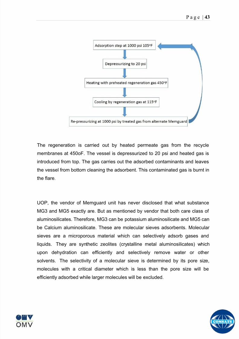
8102019 Gas sweetening Plant
httpslidepdfcomreaderfullgas-sweetening-plant 4762
P a g e | 43
The regeneration is carried out by heated permeate gas from the recycle
membranes at 450oF The vessel is depressurized to 20 psi and heated gas is
introduced from top The gas carries out the adsorbed contaminants and leaves
the vessel from bottom cleaning the adsorbent This contaminated gas is burnt in
the flare
UOP the vendor of Memguard unit has never disclosed that what substance
MG3 and MG5 exactly are But as mentioned by vendor that both care class of
aluminosilicates Therefore MG3 can be potassium aluminosilicate and MG5 can
be Calcium aluminosilicate These are molecular sieves adsorbents Molecular
sieves are a microporous material which can selectively adsorb gases andliquids They are synthetic zeolites (crystalline metal aluminosilicates) which
upon dehydration can efficiently and selectively remove water or other
solvents The selectivity of a molecular sieve is determined by its pore size
molecules with a critical diameter which is less than the pore size will be
efficiently adsorbed while larger molecules will be excluded
8102019 Gas sweetening Plant
httpslidepdfcomreaderfullgas-sweetening-plant 4862
P a g e | 44
3A Molecular Sieve Adsorbent
The 3A molecular sieve adsorbent has a 3 angstrom (3A) pore size which means
that any molecule that is larger than the 3 angstrom pores will not be adsorbed
The 3A molecular sieve is the potassium type of A crystalline structure and is a
form of alkali Aluminosilicate For a 3A molecular sieve the sequence rate that
adsorption occurs is He Ne N and H2O
Due to the crystalline structure molecular sieves that have a 3 angstrom pore
size have a very high rate of adsorption and properties that promote a longer life
for products treated by the sieve The most common use for the 3A molecular
sieve is to remove water and moisture from materials that are in gas and liquid
form
5A Molecular Sieve Adsorbent
These are molecular sieve adsorbents with a pore size of 5 angstrom (5A) 5A
molecular sieves are unable to adsorb any molecules or impurities that are
smaller than 5A It is calcium form of type A crystalline structure and is form of analkali-aluminosilicate that is most commonly used to separate isomerous alkanes
from normal alkanes and to co-adsorb moisture and water along with carbon
dioxide from gases In additional 5A molecular sieves are used for gaseous
pressure swing adsorption (PSA)mdashthat is to separate particular gases from other
gases
Adsorption of nC4H10
Adsorption of nC4H10
Adsorption of C3H8 to C22H46
Adsorption of Freon-12 (dichlorodifluoromethane)
Natural gas drying
Normal- and iso-paraffin separation
Separation of aromatic
8102019 Gas sweetening Plant
httpslidepdfcomreaderfullgas-sweetening-plant 4962
P a g e | 45
Inlet Composition of Memguard vessel
COMPSOSITION MOLE
CARBON DIOXIDE 1096
MEHTANE 8593
ETHANE 173
PROPANE 023
I-BUTANE 008
N BUTANE 004
PENTANES 004
HEXANE + 000
NITROGEN 076
WATER 007
Outlet Composition of Memguard vessel
COMPSOSITION MOLE
CARBON DIOXIDE 1098
MEHTANE 8608
ETHANE 173
PROPANE 023
I-BUTANE 008N BUTANE 004
PENTANES 004
HEXANE + 000
NITROGENT 076
WATER 000
H2S polisher
The H2S polishing unit has been designed to treat 187 MMscfday of natural gas
containing up to 11 CO2 and 21 ppm H2S where the level of the CO2 and H2S
is reduced using a MemGuard Membrane separation unit The unit is situated
down-stream of the membrane unit and will further reduce the level of H2S in the
processed gas to a sales gas specification of 38 ppm
8102019 Gas sweetening Plant
httpslidepdfcomreaderfullgas-sweetening-plant 5062
P a g e | 46
This process uses three non-regenerable fixed bed absorber vessels using a low
temperature high activity absorbent The absorbent is a mixture of activated
metal oxides (mainly zinc oxide) The three towers can are generally operated in
parallel arrangement but on demand can be used in series (any of alternate
arrangements of A B C vessels) as shown in figure
The higher sales gas flow rate increased the catalyst consumption and
replacement frequency
ZnO + H2S =gt ZnS + H20
Routine samples are taken from the beds to provide a check on each bed
performance and to follow the saturation profile during the absorbent life After
the adsorbent has been fully utilized the adsorption vessels are recharged with
new adsorbent discarding the utilized one in a safe manner
109oF
1215 psig
Before H2S Polishing After H2S Polishing
8102019 Gas sweetening Plant
httpslidepdfcomreaderfullgas-sweetening-plant 5162
P a g e | 47
Figure
H2S Tower
Inlet pipe
4 Drums of 19mm
ceramic Balls
6 Micron mesh
5 Drums of 50mmceramic
1 Drums of19mm ceramic
01 Drums of6mm ceramic
112 drums of
Catalist ZnO
8102019 Gas sweetening Plant
httpslidepdfcomreaderfullgas-sweetening-plant 5262
P a g e | 48
Recycle Compressor
The permeate gas of the primary membrane unit carries recoverable amount of
CH4 It is fed to recycle membrane unit for further CH 4 recovery But the
permeate pressure from primary membranes which has been reduced to 12 psi
must be regenerated to 1200 psi for the gas to be fed again to the system For
this purpose we have employed recycle compressor The compressor is a four
stage centrifugal compressor It is driven by gas turbine of 31200 HP It has 25
MW producing capacity
Figure Recycle Compressor Process Flow Diagram
8102019 Gas sweetening Plant
httpslidepdfcomreaderfullgas-sweetening-plant 5362
P a g e | 49
Sales Gas Compressor
Gas from H2S polishing unit is sent to sales gas compressor where its pressure
is enhanced to 1100 psi so it may be injected to SNGPL high pressure trunk line
Sales gas compressor is single stage gas turbine driven
Figure Process Flow of Sales Gas Compressor
8102019 Gas sweetening Plant
httpslidepdfcomreaderfullgas-sweetening-plant 5462
P a g e | 50
Cooling Towers
A cooling tower is a heat rejection device which extracts waste heat to theatmosphere through the cooling of a water stream to a lower temperature Hot
water from the system enters the cooling tower and is distributed over the fill
(heat transfer surface) Air is induced or forced through the fill causing a small
portion of the water to evaporate This evaporation removes heat from the
remaining water which is collected in the cold water basin and returned to the
system to absorb more heat Each cooling tower line although operating under
the same basic principle of operation is arranged a little differently
Types
Natural draft mdash Utilizes buoyancy via a tall chimney Warm moist air naturally
rises due to the density differential compared to the dry cooler outside air Warm
moist air is less dense than drier air at the same pressure This moist air
buoyancy produces an upwards current of air through the tower
Mechanical draft mdash Uses power-driven fan motors to force or draw airthrough the tower
o Induced draft mdash A mechanical draft tower with a fan at the
discharge (at the top) which pulls air up through the tower The fan
induces hot moist air out the discharge This produces low entering
and high exiting air velocities reducing the possibility of
recirculation in which discharged air flows back into the air intake
o Forced draft mdash A mechanical draft tower with a blower type fan at
the intake The fan forces air into the tower creating high entering
and low exiting air velocities The low exiting velocity is much more
susceptible to recirculation This fanfill geometry is also known as
blow-through
8102019 Gas sweetening Plant
httpslidepdfcomreaderfullgas-sweetening-plant 5562
P a g e | 51
Forced Draft Cooling Tower Vs Induced Draft Cooling Tower
Induced Draft Cooling Tower have the ability to handle large water flow
rate than Forced Draft Cooling Tower
Induced Draft Cooling Tower is suitable for large cell sizes and fan sizes
as compared with Forced Draft Larger fan size may result in greater
efficiency and consequently lower power and sound level
Forced Draft Cooling Tower can be square or rectangular type only
however Induced Draft Cooling Towers can be round square or
rectangular type
Induced Draft Cooling Tower uses more compact ground area than Forced
Draft Cooling Tower equivalent capacity due to absence of fan on one
side
Fan equipment is warm exhaust air is less liable to icing up in winter
operation (Cold Countries)
Higher velocity in Forced Draft Cooling Tower cause drop in suspension
and cause additional static resistance to system
Configuration
There are two main configurations of factory assembled cooling towers crossflow
and counterflow In crossflow cooling towers the water flows vertically down the
fill as air flows horizontally across In counterflow cooling towers the water flows
vertically down the fill as air flows vertically up
Crossflow Configuration Counterflow Configuration
8102019 Gas sweetening Plant
httpslidepdfcomreaderfullgas-sweetening-plant 5662
P a g e | 52
Drift mdash Water droplets that are carried out of the cooling tower with the exhaust
air Drift droplets have the same concentration of impurities as the water entering
the tower The drift rate is typically reduced by employing baffle-like devices
called drift eliminators through which the air must travel after leaving the fill and
spray zones of the tower
Blow-out mdash Water droplets blown out of the cooling tower by wind generally at
the air inlet openings Water may also be lost in the absence of wind through
splashing or misting Devices such as wind screens louvers splash deflectors
and water diverters are used to limit these losses
Blow-down mdash The portion of the circulating water flow that is removed (usually
discharged to a drain) in order to maintain the amount of Total Dissolved Solids
(TDS) and other impurities at an acceptably low level Higher TDS concentration
in solution may result from greater cooling tower efficiency However the higher
the TDS concentration the greater the risk of scale biological growth and
corrosion
Make-up mdash The water that must be added to the circulating water system in
order to compensate for water losses such as evaporation drift loss blow-out
blow-down etc
Approach mdash The approach is the difference in temperature between the cooled-
water temperature and the entering-air wet bulb temperature
Range mdash The range is the temperature difference between the warm water inlet
and cooled water exit
Fill mdash Inside the tower fills are added to increase contact surface as well as
contact time between air and water to provide better heat transfer The efficiency
of the tower depends on the selection and amount of fill
8102019 Gas sweetening Plant
httpslidepdfcomreaderfullgas-sweetening-plant 5762
P a g e | 53
There are two types of fills that may be used
o Film type fill (causes water to spread into a thin film)
o Splash type fill (breaks up falling stream of water and interrupts its
vertical progress)
Important
Scale build up is controlled by adding chemicals to the cooling loop and diluting
the concentration by blow down and make-up Following chemicals are added to
the Cooling to control CorrosionSale and microbial growth
Corrosion Inhibitor To control corrosion in the Cooling system
Dispersant To kept ions in suspension to avoid settle down and buildup
Sodium hypo Chlorite To Control microbial Growth
Acid To control Alkalinity in the system
High Stress Polymer To run the system at higher conductivity It is a
multifunctional polymer for Zinc amp Phosphate stabilization in cooling tower
Fin Fan Cooler
Fin fan heat exchanger is simply a pressure vessel which cools a circulating fluid
within finned tubes by forcing ambient air over the exterior of the tubes A
common example of an air cooler is a carrsquos radiator Fin Fan Coolers are used in
any application where large quantities of heat need to be transferred This
includes chemical and petrochemical industries power stations waste-to-energy
facilities as well as steelworks
Fin Fan Cooler are used for two primary reasons
They increase plant efficiency
They are a green solution as compared to cooling towers and shell and
tube heat exchangers because they do not require an auxiliary water
8102019 Gas sweetening Plant
httpslidepdfcomreaderfullgas-sweetening-plant 5862
P a g e | 54
supply (water lost due to drift and evaporation plus no water treatment
chemicals are required)
Figure General Overview of Fin Fan Cooler
Produced Water
The produced water system receives liquid from the equipment Miano slug
catcher train 1 and 2 inlet separators and is fed to three phase separator where
water oil and gas is separated The gases produced are burnt in incinerator
whereas hydrocarbon liquid is stored to be sold Liquid from compressors
recycle inlet separator recycle feed scrubber high and low pressure slug
catchers is passed to degasser Separated water is injected down the earth
Incinerator
The term incinerate means to burn something until nothing is left but ashes An
incinerator is a unit or facility used to burn trash and other types of waste until it is
reduced to ash An incinerator is constructed of heavy well-insulated materials
so that it does not give off extreme amounts of external heat The high levels of
heat are kept inside the furnace or unit so that the waste is burned quickly and
efficiently If the heat were allowed to escape the waste would not burn as
completely or as rapidly
8102019 Gas sweetening Plant
httpslidepdfcomreaderfullgas-sweetening-plant 5962
P a g e | 55
Control System
The plant is controlled at CCR (Central Control Room) by PLCs (Programmable
Logic Controllers) through fiber optic control line All control parameters are
received at LER (Local Equipment Room) via two optic fiber control lines One
being primary and other secondary operating in redundancy ie if primary fails
control shifts to secondary These control parameters are sent to CCR via single
optic fiber cable
Safety System
Wellheads and Gas Processing Plant have their own Fire amp Gas detection
systems emergency shutdown (ESD) Plant has a fault tolerant controller It is
based on Triple Modular Redundant (TMR) architecture manufactured by
Triconex The TMR system is based on three isolated parallel control systems
integrated into one system The system operates on a two out of three voting
principle which provides high integrity error free uninterrupted operation with no
single point of failure The TMR receives inputs from Process Sensors Manual
Switches Fire amp Gas Detectors Packaged Equipment Control Systems and
Product Exporting Facilities The TMR carries out cause and effect processing on
the data received and where necessary produces output signals Outputs from
the TMR are hard wired directly to ESD shutdown and blow down valve
solenoids motor control instrumentelectrical interfaces to control electrical
drives package equipment logic control systems manifold area as well as
telecoms
The operator in central control room is able to accept alarms and once the fault
has been cleared reset the input All the control systems are centralized to a
single interface All the PLCs (Programmable Logic Controllers) communicate with
the servers and servers communicate with the clients through Ethernet connectivity
Centralization eases the navigation of different systems at a common interface
Emergency Shutdown
The ESD system receives inputs from field mounted instrumentation on the process
8102019 Gas sweetening Plant
httpslidepdfcomreaderfullgas-sweetening-plant 6062
P a g e | 56
and utility equipment and initiates executive actions appropriate to the level of ESD
The system is an Active system which is in standby and will activate when in an
alarm or fault condition The Kadanwari Gas Process Facility ESD system is
comprised of five (5) levels The emergency severity decreases with increasing ESD
level number
ESD 1
This shutdown level is automatically initiated by fire major gas leak or a detected
toxic atmosphere in the process area of the plant or manually from CCR A level 1
shutdown will cause all production to cease close all emergency shutdown
valves stop the process and shutdown of the main power generation The
emergency vent valves to the stack will open and in addition all equipment of zone 1
certified will be isolated This is the highest level of ESD and will cause the following
to occur
All Shutdown Valves (SDVs) on the process facility will close All slowdown Valves (BDVs) on the process facility will open
All Main Gas Driven Generators will be tripped
Emergency Diesel Generator will start
All electrical power to process and utility rotating equipment will be
isolated
Wellhead Choke Valves Close Wing Valves Close Upper Master Valve
(UMV) Close
ESD 2
This shutdown level is activated automatically if a major process or utility failure
occurs or manually from CCR All production to the plant from the wellhead is
stopped All emergency shutdown valves trip to their fail safe position
Venting shall be as specified This level of ESD will cause the following to occur
8102019 Gas sweetening Plant
httpslidepdfcomreaderfullgas-sweetening-plant 6162
P a g e | 57
All Shutdown Valves (SDVs) on the process facility will close
All electrical power to process and utility rotating equipment will be
isolated
Wellhead Choke Valve Close Wing Valves Close and Upper Master Valve(UMV) Close
ESD 3
The level 3 shutdown isolates and stops a single process train only Production
continues via the other train This ESD level is initiated by process conditions or
operator at local panel This level of ESD will cause the following to occur
ESD 3A Train 1 production to cease
ESD 3B Train 2 production to cease
All online wellhead choke valves go to minimum flow ie (1O )
ESD 4
A level 4 shutdown shall cease all production from an entire field either
Kadanwari or Miano upstream of the associated slug catchers ESD 4K for
Kadanwari amp ESD 4M for Miano This ESD level is initiated automatically by slug
catcher abnormal process conditions This level of ESD will cause the following
to occur
All SDVs close isolating the relevant slug catcher and its upstream gas
production facility from the Kadanwari Gas Processing Plant
All Wellhead Choke Valves Close Wing Valves Close and Upper MasterValves (UMV) of the relevant gas production facility Close
A parallel timer is provided to close within 10 second if not closed in given
time SSSV seals the well
ESD 5
A level 5 shutdown represents equipment shutdown for the protection of the
individual equipment without any change in the process This level of ESD is for the
protection of various pieces of equipment and is initiated by its own inputs eg
8102019 Gas sweetening Plant
httpslidepdfcomreaderfullgas-sweetening-plant 6262
8102019 Gas sweetening Plant
httpslidepdfcomreaderfullgas-sweetening-plant 4862
P a g e | 44
3A Molecular Sieve Adsorbent
The 3A molecular sieve adsorbent has a 3 angstrom (3A) pore size which means
that any molecule that is larger than the 3 angstrom pores will not be adsorbed
The 3A molecular sieve is the potassium type of A crystalline structure and is a
form of alkali Aluminosilicate For a 3A molecular sieve the sequence rate that
adsorption occurs is He Ne N and H2O
Due to the crystalline structure molecular sieves that have a 3 angstrom pore
size have a very high rate of adsorption and properties that promote a longer life
for products treated by the sieve The most common use for the 3A molecular
sieve is to remove water and moisture from materials that are in gas and liquid
form
5A Molecular Sieve Adsorbent
These are molecular sieve adsorbents with a pore size of 5 angstrom (5A) 5A
molecular sieves are unable to adsorb any molecules or impurities that are
smaller than 5A It is calcium form of type A crystalline structure and is form of analkali-aluminosilicate that is most commonly used to separate isomerous alkanes
from normal alkanes and to co-adsorb moisture and water along with carbon
dioxide from gases In additional 5A molecular sieves are used for gaseous
pressure swing adsorption (PSA)mdashthat is to separate particular gases from other
gases
Adsorption of nC4H10
Adsorption of nC4H10
Adsorption of C3H8 to C22H46
Adsorption of Freon-12 (dichlorodifluoromethane)
Natural gas drying
Normal- and iso-paraffin separation
Separation of aromatic
8102019 Gas sweetening Plant
httpslidepdfcomreaderfullgas-sweetening-plant 4962
P a g e | 45
Inlet Composition of Memguard vessel
COMPSOSITION MOLE
CARBON DIOXIDE 1096
MEHTANE 8593
ETHANE 173
PROPANE 023
I-BUTANE 008
N BUTANE 004
PENTANES 004
HEXANE + 000
NITROGEN 076
WATER 007
Outlet Composition of Memguard vessel
COMPSOSITION MOLE
CARBON DIOXIDE 1098
MEHTANE 8608
ETHANE 173
PROPANE 023
I-BUTANE 008N BUTANE 004
PENTANES 004
HEXANE + 000
NITROGENT 076
WATER 000
H2S polisher
The H2S polishing unit has been designed to treat 187 MMscfday of natural gas
containing up to 11 CO2 and 21 ppm H2S where the level of the CO2 and H2S
is reduced using a MemGuard Membrane separation unit The unit is situated
down-stream of the membrane unit and will further reduce the level of H2S in the
processed gas to a sales gas specification of 38 ppm
8102019 Gas sweetening Plant
httpslidepdfcomreaderfullgas-sweetening-plant 5062
P a g e | 46
This process uses three non-regenerable fixed bed absorber vessels using a low
temperature high activity absorbent The absorbent is a mixture of activated
metal oxides (mainly zinc oxide) The three towers can are generally operated in
parallel arrangement but on demand can be used in series (any of alternate
arrangements of A B C vessels) as shown in figure
The higher sales gas flow rate increased the catalyst consumption and
replacement frequency
ZnO + H2S =gt ZnS + H20
Routine samples are taken from the beds to provide a check on each bed
performance and to follow the saturation profile during the absorbent life After
the adsorbent has been fully utilized the adsorption vessels are recharged with
new adsorbent discarding the utilized one in a safe manner
109oF
1215 psig
Before H2S Polishing After H2S Polishing
8102019 Gas sweetening Plant
httpslidepdfcomreaderfullgas-sweetening-plant 5162
P a g e | 47
Figure
H2S Tower
Inlet pipe
4 Drums of 19mm
ceramic Balls
6 Micron mesh
5 Drums of 50mmceramic
1 Drums of19mm ceramic
01 Drums of6mm ceramic
112 drums of
Catalist ZnO
8102019 Gas sweetening Plant
httpslidepdfcomreaderfullgas-sweetening-plant 5262
P a g e | 48
Recycle Compressor
The permeate gas of the primary membrane unit carries recoverable amount of
CH4 It is fed to recycle membrane unit for further CH 4 recovery But the
permeate pressure from primary membranes which has been reduced to 12 psi
must be regenerated to 1200 psi for the gas to be fed again to the system For
this purpose we have employed recycle compressor The compressor is a four
stage centrifugal compressor It is driven by gas turbine of 31200 HP It has 25
MW producing capacity
Figure Recycle Compressor Process Flow Diagram
8102019 Gas sweetening Plant
httpslidepdfcomreaderfullgas-sweetening-plant 5362
P a g e | 49
Sales Gas Compressor
Gas from H2S polishing unit is sent to sales gas compressor where its pressure
is enhanced to 1100 psi so it may be injected to SNGPL high pressure trunk line
Sales gas compressor is single stage gas turbine driven
Figure Process Flow of Sales Gas Compressor
8102019 Gas sweetening Plant
httpslidepdfcomreaderfullgas-sweetening-plant 5462
P a g e | 50
Cooling Towers
A cooling tower is a heat rejection device which extracts waste heat to theatmosphere through the cooling of a water stream to a lower temperature Hot
water from the system enters the cooling tower and is distributed over the fill
(heat transfer surface) Air is induced or forced through the fill causing a small
portion of the water to evaporate This evaporation removes heat from the
remaining water which is collected in the cold water basin and returned to the
system to absorb more heat Each cooling tower line although operating under
the same basic principle of operation is arranged a little differently
Types
Natural draft mdash Utilizes buoyancy via a tall chimney Warm moist air naturally
rises due to the density differential compared to the dry cooler outside air Warm
moist air is less dense than drier air at the same pressure This moist air
buoyancy produces an upwards current of air through the tower
Mechanical draft mdash Uses power-driven fan motors to force or draw airthrough the tower
o Induced draft mdash A mechanical draft tower with a fan at the
discharge (at the top) which pulls air up through the tower The fan
induces hot moist air out the discharge This produces low entering
and high exiting air velocities reducing the possibility of
recirculation in which discharged air flows back into the air intake
o Forced draft mdash A mechanical draft tower with a blower type fan at
the intake The fan forces air into the tower creating high entering
and low exiting air velocities The low exiting velocity is much more
susceptible to recirculation This fanfill geometry is also known as
blow-through
8102019 Gas sweetening Plant
httpslidepdfcomreaderfullgas-sweetening-plant 5562
P a g e | 51
Forced Draft Cooling Tower Vs Induced Draft Cooling Tower
Induced Draft Cooling Tower have the ability to handle large water flow
rate than Forced Draft Cooling Tower
Induced Draft Cooling Tower is suitable for large cell sizes and fan sizes
as compared with Forced Draft Larger fan size may result in greater
efficiency and consequently lower power and sound level
Forced Draft Cooling Tower can be square or rectangular type only
however Induced Draft Cooling Towers can be round square or
rectangular type
Induced Draft Cooling Tower uses more compact ground area than Forced
Draft Cooling Tower equivalent capacity due to absence of fan on one
side
Fan equipment is warm exhaust air is less liable to icing up in winter
operation (Cold Countries)
Higher velocity in Forced Draft Cooling Tower cause drop in suspension
and cause additional static resistance to system
Configuration
There are two main configurations of factory assembled cooling towers crossflow
and counterflow In crossflow cooling towers the water flows vertically down the
fill as air flows horizontally across In counterflow cooling towers the water flows
vertically down the fill as air flows vertically up
Crossflow Configuration Counterflow Configuration
8102019 Gas sweetening Plant
httpslidepdfcomreaderfullgas-sweetening-plant 5662
P a g e | 52
Drift mdash Water droplets that are carried out of the cooling tower with the exhaust
air Drift droplets have the same concentration of impurities as the water entering
the tower The drift rate is typically reduced by employing baffle-like devices
called drift eliminators through which the air must travel after leaving the fill and
spray zones of the tower
Blow-out mdash Water droplets blown out of the cooling tower by wind generally at
the air inlet openings Water may also be lost in the absence of wind through
splashing or misting Devices such as wind screens louvers splash deflectors
and water diverters are used to limit these losses
Blow-down mdash The portion of the circulating water flow that is removed (usually
discharged to a drain) in order to maintain the amount of Total Dissolved Solids
(TDS) and other impurities at an acceptably low level Higher TDS concentration
in solution may result from greater cooling tower efficiency However the higher
the TDS concentration the greater the risk of scale biological growth and
corrosion
Make-up mdash The water that must be added to the circulating water system in
order to compensate for water losses such as evaporation drift loss blow-out
blow-down etc
Approach mdash The approach is the difference in temperature between the cooled-
water temperature and the entering-air wet bulb temperature
Range mdash The range is the temperature difference between the warm water inlet
and cooled water exit
Fill mdash Inside the tower fills are added to increase contact surface as well as
contact time between air and water to provide better heat transfer The efficiency
of the tower depends on the selection and amount of fill
8102019 Gas sweetening Plant
httpslidepdfcomreaderfullgas-sweetening-plant 5762
P a g e | 53
There are two types of fills that may be used
o Film type fill (causes water to spread into a thin film)
o Splash type fill (breaks up falling stream of water and interrupts its
vertical progress)
Important
Scale build up is controlled by adding chemicals to the cooling loop and diluting
the concentration by blow down and make-up Following chemicals are added to
the Cooling to control CorrosionSale and microbial growth
Corrosion Inhibitor To control corrosion in the Cooling system
Dispersant To kept ions in suspension to avoid settle down and buildup
Sodium hypo Chlorite To Control microbial Growth
Acid To control Alkalinity in the system
High Stress Polymer To run the system at higher conductivity It is a
multifunctional polymer for Zinc amp Phosphate stabilization in cooling tower
Fin Fan Cooler
Fin fan heat exchanger is simply a pressure vessel which cools a circulating fluid
within finned tubes by forcing ambient air over the exterior of the tubes A
common example of an air cooler is a carrsquos radiator Fin Fan Coolers are used in
any application where large quantities of heat need to be transferred This
includes chemical and petrochemical industries power stations waste-to-energy
facilities as well as steelworks
Fin Fan Cooler are used for two primary reasons
They increase plant efficiency
They are a green solution as compared to cooling towers and shell and
tube heat exchangers because they do not require an auxiliary water
8102019 Gas sweetening Plant
httpslidepdfcomreaderfullgas-sweetening-plant 5862
P a g e | 54
supply (water lost due to drift and evaporation plus no water treatment
chemicals are required)
Figure General Overview of Fin Fan Cooler
Produced Water
The produced water system receives liquid from the equipment Miano slug
catcher train 1 and 2 inlet separators and is fed to three phase separator where
water oil and gas is separated The gases produced are burnt in incinerator
whereas hydrocarbon liquid is stored to be sold Liquid from compressors
recycle inlet separator recycle feed scrubber high and low pressure slug
catchers is passed to degasser Separated water is injected down the earth
Incinerator
The term incinerate means to burn something until nothing is left but ashes An
incinerator is a unit or facility used to burn trash and other types of waste until it is
reduced to ash An incinerator is constructed of heavy well-insulated materials
so that it does not give off extreme amounts of external heat The high levels of
heat are kept inside the furnace or unit so that the waste is burned quickly and
efficiently If the heat were allowed to escape the waste would not burn as
completely or as rapidly
8102019 Gas sweetening Plant
httpslidepdfcomreaderfullgas-sweetening-plant 5962
P a g e | 55
Control System
The plant is controlled at CCR (Central Control Room) by PLCs (Programmable
Logic Controllers) through fiber optic control line All control parameters are
received at LER (Local Equipment Room) via two optic fiber control lines One
being primary and other secondary operating in redundancy ie if primary fails
control shifts to secondary These control parameters are sent to CCR via single
optic fiber cable
Safety System
Wellheads and Gas Processing Plant have their own Fire amp Gas detection
systems emergency shutdown (ESD) Plant has a fault tolerant controller It is
based on Triple Modular Redundant (TMR) architecture manufactured by
Triconex The TMR system is based on three isolated parallel control systems
integrated into one system The system operates on a two out of three voting
principle which provides high integrity error free uninterrupted operation with no
single point of failure The TMR receives inputs from Process Sensors Manual
Switches Fire amp Gas Detectors Packaged Equipment Control Systems and
Product Exporting Facilities The TMR carries out cause and effect processing on
the data received and where necessary produces output signals Outputs from
the TMR are hard wired directly to ESD shutdown and blow down valve
solenoids motor control instrumentelectrical interfaces to control electrical
drives package equipment logic control systems manifold area as well as
telecoms
The operator in central control room is able to accept alarms and once the fault
has been cleared reset the input All the control systems are centralized to a
single interface All the PLCs (Programmable Logic Controllers) communicate with
the servers and servers communicate with the clients through Ethernet connectivity
Centralization eases the navigation of different systems at a common interface
Emergency Shutdown
The ESD system receives inputs from field mounted instrumentation on the process
8102019 Gas sweetening Plant
httpslidepdfcomreaderfullgas-sweetening-plant 6062
P a g e | 56
and utility equipment and initiates executive actions appropriate to the level of ESD
The system is an Active system which is in standby and will activate when in an
alarm or fault condition The Kadanwari Gas Process Facility ESD system is
comprised of five (5) levels The emergency severity decreases with increasing ESD
level number
ESD 1
This shutdown level is automatically initiated by fire major gas leak or a detected
toxic atmosphere in the process area of the plant or manually from CCR A level 1
shutdown will cause all production to cease close all emergency shutdown
valves stop the process and shutdown of the main power generation The
emergency vent valves to the stack will open and in addition all equipment of zone 1
certified will be isolated This is the highest level of ESD and will cause the following
to occur
All Shutdown Valves (SDVs) on the process facility will close All slowdown Valves (BDVs) on the process facility will open
All Main Gas Driven Generators will be tripped
Emergency Diesel Generator will start
All electrical power to process and utility rotating equipment will be
isolated
Wellhead Choke Valves Close Wing Valves Close Upper Master Valve
(UMV) Close
ESD 2
This shutdown level is activated automatically if a major process or utility failure
occurs or manually from CCR All production to the plant from the wellhead is
stopped All emergency shutdown valves trip to their fail safe position
Venting shall be as specified This level of ESD will cause the following to occur
8102019 Gas sweetening Plant
httpslidepdfcomreaderfullgas-sweetening-plant 6162
P a g e | 57
All Shutdown Valves (SDVs) on the process facility will close
All electrical power to process and utility rotating equipment will be
isolated
Wellhead Choke Valve Close Wing Valves Close and Upper Master Valve(UMV) Close
ESD 3
The level 3 shutdown isolates and stops a single process train only Production
continues via the other train This ESD level is initiated by process conditions or
operator at local panel This level of ESD will cause the following to occur
ESD 3A Train 1 production to cease
ESD 3B Train 2 production to cease
All online wellhead choke valves go to minimum flow ie (1O )
ESD 4
A level 4 shutdown shall cease all production from an entire field either
Kadanwari or Miano upstream of the associated slug catchers ESD 4K for
Kadanwari amp ESD 4M for Miano This ESD level is initiated automatically by slug
catcher abnormal process conditions This level of ESD will cause the following
to occur
All SDVs close isolating the relevant slug catcher and its upstream gas
production facility from the Kadanwari Gas Processing Plant
All Wellhead Choke Valves Close Wing Valves Close and Upper MasterValves (UMV) of the relevant gas production facility Close
A parallel timer is provided to close within 10 second if not closed in given
time SSSV seals the well
ESD 5
A level 5 shutdown represents equipment shutdown for the protection of the
individual equipment without any change in the process This level of ESD is for the
protection of various pieces of equipment and is initiated by its own inputs eg
8102019 Gas sweetening Plant
httpslidepdfcomreaderfullgas-sweetening-plant 6262
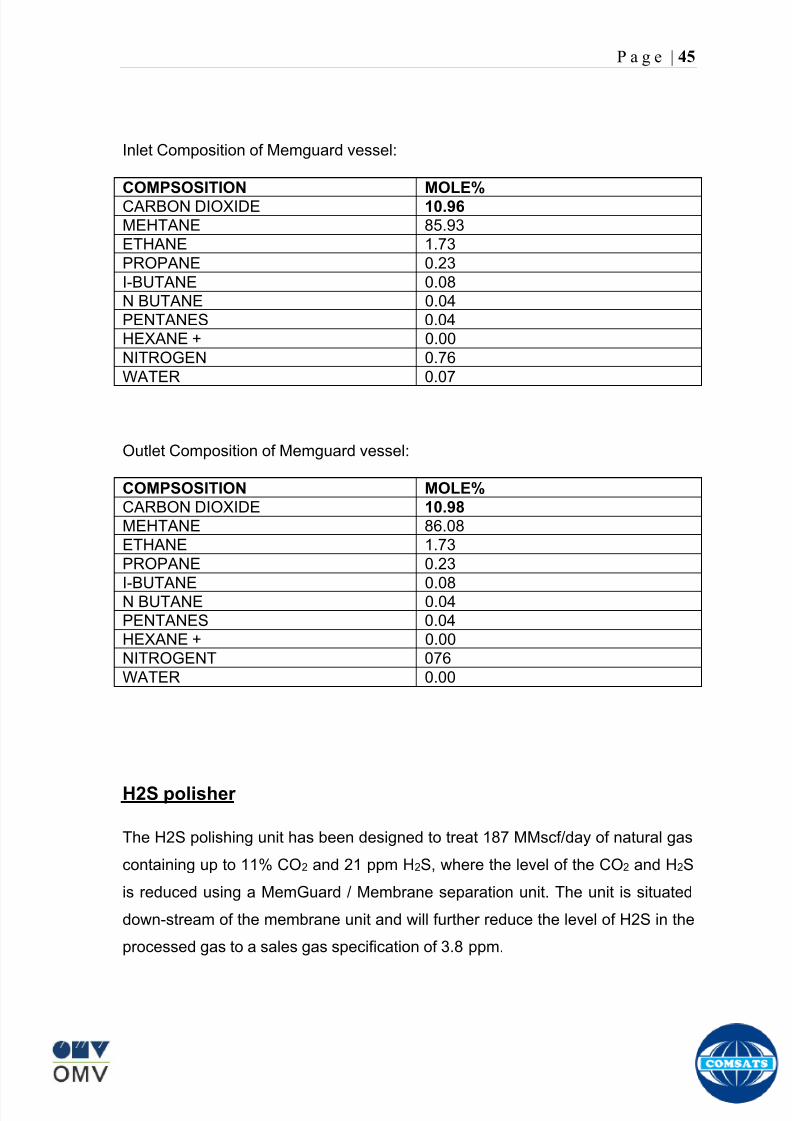
8102019 Gas sweetening Plant
httpslidepdfcomreaderfullgas-sweetening-plant 4962
P a g e | 45
Inlet Composition of Memguard vessel
COMPSOSITION MOLE
CARBON DIOXIDE 1096
MEHTANE 8593
ETHANE 173
PROPANE 023
I-BUTANE 008
N BUTANE 004
PENTANES 004
HEXANE + 000
NITROGEN 076
WATER 007
Outlet Composition of Memguard vessel
COMPSOSITION MOLE
CARBON DIOXIDE 1098
MEHTANE 8608
ETHANE 173
PROPANE 023
I-BUTANE 008N BUTANE 004
PENTANES 004
HEXANE + 000
NITROGENT 076
WATER 000
H2S polisher
The H2S polishing unit has been designed to treat 187 MMscfday of natural gas
containing up to 11 CO2 and 21 ppm H2S where the level of the CO2 and H2S
is reduced using a MemGuard Membrane separation unit The unit is situated
down-stream of the membrane unit and will further reduce the level of H2S in the
processed gas to a sales gas specification of 38 ppm
8102019 Gas sweetening Plant
httpslidepdfcomreaderfullgas-sweetening-plant 5062
P a g e | 46
This process uses three non-regenerable fixed bed absorber vessels using a low
temperature high activity absorbent The absorbent is a mixture of activated
metal oxides (mainly zinc oxide) The three towers can are generally operated in
parallel arrangement but on demand can be used in series (any of alternate
arrangements of A B C vessels) as shown in figure
The higher sales gas flow rate increased the catalyst consumption and
replacement frequency
ZnO + H2S =gt ZnS + H20
Routine samples are taken from the beds to provide a check on each bed
performance and to follow the saturation profile during the absorbent life After
the adsorbent has been fully utilized the adsorption vessels are recharged with
new adsorbent discarding the utilized one in a safe manner
109oF
1215 psig
Before H2S Polishing After H2S Polishing
8102019 Gas sweetening Plant
httpslidepdfcomreaderfullgas-sweetening-plant 5162
P a g e | 47
Figure
H2S Tower
Inlet pipe
4 Drums of 19mm
ceramic Balls
6 Micron mesh
5 Drums of 50mmceramic
1 Drums of19mm ceramic
01 Drums of6mm ceramic
112 drums of
Catalist ZnO
8102019 Gas sweetening Plant
httpslidepdfcomreaderfullgas-sweetening-plant 5262
P a g e | 48
Recycle Compressor
The permeate gas of the primary membrane unit carries recoverable amount of
CH4 It is fed to recycle membrane unit for further CH 4 recovery But the
permeate pressure from primary membranes which has been reduced to 12 psi
must be regenerated to 1200 psi for the gas to be fed again to the system For
this purpose we have employed recycle compressor The compressor is a four
stage centrifugal compressor It is driven by gas turbine of 31200 HP It has 25
MW producing capacity
Figure Recycle Compressor Process Flow Diagram
8102019 Gas sweetening Plant
httpslidepdfcomreaderfullgas-sweetening-plant 5362
P a g e | 49
Sales Gas Compressor
Gas from H2S polishing unit is sent to sales gas compressor where its pressure
is enhanced to 1100 psi so it may be injected to SNGPL high pressure trunk line
Sales gas compressor is single stage gas turbine driven
Figure Process Flow of Sales Gas Compressor
8102019 Gas sweetening Plant
httpslidepdfcomreaderfullgas-sweetening-plant 5462
P a g e | 50
Cooling Towers
A cooling tower is a heat rejection device which extracts waste heat to theatmosphere through the cooling of a water stream to a lower temperature Hot
water from the system enters the cooling tower and is distributed over the fill
(heat transfer surface) Air is induced or forced through the fill causing a small
portion of the water to evaporate This evaporation removes heat from the
remaining water which is collected in the cold water basin and returned to the
system to absorb more heat Each cooling tower line although operating under
the same basic principle of operation is arranged a little differently
Types
Natural draft mdash Utilizes buoyancy via a tall chimney Warm moist air naturally
rises due to the density differential compared to the dry cooler outside air Warm
moist air is less dense than drier air at the same pressure This moist air
buoyancy produces an upwards current of air through the tower
Mechanical draft mdash Uses power-driven fan motors to force or draw airthrough the tower
o Induced draft mdash A mechanical draft tower with a fan at the
discharge (at the top) which pulls air up through the tower The fan
induces hot moist air out the discharge This produces low entering
and high exiting air velocities reducing the possibility of
recirculation in which discharged air flows back into the air intake
o Forced draft mdash A mechanical draft tower with a blower type fan at
the intake The fan forces air into the tower creating high entering
and low exiting air velocities The low exiting velocity is much more
susceptible to recirculation This fanfill geometry is also known as
blow-through
8102019 Gas sweetening Plant
httpslidepdfcomreaderfullgas-sweetening-plant 5562
P a g e | 51
Forced Draft Cooling Tower Vs Induced Draft Cooling Tower
Induced Draft Cooling Tower have the ability to handle large water flow
rate than Forced Draft Cooling Tower
Induced Draft Cooling Tower is suitable for large cell sizes and fan sizes
as compared with Forced Draft Larger fan size may result in greater
efficiency and consequently lower power and sound level
Forced Draft Cooling Tower can be square or rectangular type only
however Induced Draft Cooling Towers can be round square or
rectangular type
Induced Draft Cooling Tower uses more compact ground area than Forced
Draft Cooling Tower equivalent capacity due to absence of fan on one
side
Fan equipment is warm exhaust air is less liable to icing up in winter
operation (Cold Countries)
Higher velocity in Forced Draft Cooling Tower cause drop in suspension
and cause additional static resistance to system
Configuration
There are two main configurations of factory assembled cooling towers crossflow
and counterflow In crossflow cooling towers the water flows vertically down the
fill as air flows horizontally across In counterflow cooling towers the water flows
vertically down the fill as air flows vertically up
Crossflow Configuration Counterflow Configuration
8102019 Gas sweetening Plant
httpslidepdfcomreaderfullgas-sweetening-plant 5662
P a g e | 52
Drift mdash Water droplets that are carried out of the cooling tower with the exhaust
air Drift droplets have the same concentration of impurities as the water entering
the tower The drift rate is typically reduced by employing baffle-like devices
called drift eliminators through which the air must travel after leaving the fill and
spray zones of the tower
Blow-out mdash Water droplets blown out of the cooling tower by wind generally at
the air inlet openings Water may also be lost in the absence of wind through
splashing or misting Devices such as wind screens louvers splash deflectors
and water diverters are used to limit these losses
Blow-down mdash The portion of the circulating water flow that is removed (usually
discharged to a drain) in order to maintain the amount of Total Dissolved Solids
(TDS) and other impurities at an acceptably low level Higher TDS concentration
in solution may result from greater cooling tower efficiency However the higher
the TDS concentration the greater the risk of scale biological growth and
corrosion
Make-up mdash The water that must be added to the circulating water system in
order to compensate for water losses such as evaporation drift loss blow-out
blow-down etc
Approach mdash The approach is the difference in temperature between the cooled-
water temperature and the entering-air wet bulb temperature
Range mdash The range is the temperature difference between the warm water inlet
and cooled water exit
Fill mdash Inside the tower fills are added to increase contact surface as well as
contact time between air and water to provide better heat transfer The efficiency
of the tower depends on the selection and amount of fill
8102019 Gas sweetening Plant
httpslidepdfcomreaderfullgas-sweetening-plant 5762
P a g e | 53
There are two types of fills that may be used
o Film type fill (causes water to spread into a thin film)
o Splash type fill (breaks up falling stream of water and interrupts its
vertical progress)
Important
Scale build up is controlled by adding chemicals to the cooling loop and diluting
the concentration by blow down and make-up Following chemicals are added to
the Cooling to control CorrosionSale and microbial growth
Corrosion Inhibitor To control corrosion in the Cooling system
Dispersant To kept ions in suspension to avoid settle down and buildup
Sodium hypo Chlorite To Control microbial Growth
Acid To control Alkalinity in the system
High Stress Polymer To run the system at higher conductivity It is a
multifunctional polymer for Zinc amp Phosphate stabilization in cooling tower
Fin Fan Cooler
Fin fan heat exchanger is simply a pressure vessel which cools a circulating fluid
within finned tubes by forcing ambient air over the exterior of the tubes A
common example of an air cooler is a carrsquos radiator Fin Fan Coolers are used in
any application where large quantities of heat need to be transferred This
includes chemical and petrochemical industries power stations waste-to-energy
facilities as well as steelworks
Fin Fan Cooler are used for two primary reasons
They increase plant efficiency
They are a green solution as compared to cooling towers and shell and
tube heat exchangers because they do not require an auxiliary water
8102019 Gas sweetening Plant
httpslidepdfcomreaderfullgas-sweetening-plant 5862
P a g e | 54
supply (water lost due to drift and evaporation plus no water treatment
chemicals are required)
Figure General Overview of Fin Fan Cooler
Produced Water
The produced water system receives liquid from the equipment Miano slug
catcher train 1 and 2 inlet separators and is fed to three phase separator where
water oil and gas is separated The gases produced are burnt in incinerator
whereas hydrocarbon liquid is stored to be sold Liquid from compressors
recycle inlet separator recycle feed scrubber high and low pressure slug
catchers is passed to degasser Separated water is injected down the earth
Incinerator
The term incinerate means to burn something until nothing is left but ashes An
incinerator is a unit or facility used to burn trash and other types of waste until it is
reduced to ash An incinerator is constructed of heavy well-insulated materials
so that it does not give off extreme amounts of external heat The high levels of
heat are kept inside the furnace or unit so that the waste is burned quickly and
efficiently If the heat were allowed to escape the waste would not burn as
completely or as rapidly
8102019 Gas sweetening Plant
httpslidepdfcomreaderfullgas-sweetening-plant 5962
P a g e | 55
Control System
The plant is controlled at CCR (Central Control Room) by PLCs (Programmable
Logic Controllers) through fiber optic control line All control parameters are
received at LER (Local Equipment Room) via two optic fiber control lines One
being primary and other secondary operating in redundancy ie if primary fails
control shifts to secondary These control parameters are sent to CCR via single
optic fiber cable
Safety System
Wellheads and Gas Processing Plant have their own Fire amp Gas detection
systems emergency shutdown (ESD) Plant has a fault tolerant controller It is
based on Triple Modular Redundant (TMR) architecture manufactured by
Triconex The TMR system is based on three isolated parallel control systems
integrated into one system The system operates on a two out of three voting
principle which provides high integrity error free uninterrupted operation with no
single point of failure The TMR receives inputs from Process Sensors Manual
Switches Fire amp Gas Detectors Packaged Equipment Control Systems and
Product Exporting Facilities The TMR carries out cause and effect processing on
the data received and where necessary produces output signals Outputs from
the TMR are hard wired directly to ESD shutdown and blow down valve
solenoids motor control instrumentelectrical interfaces to control electrical
drives package equipment logic control systems manifold area as well as
telecoms
The operator in central control room is able to accept alarms and once the fault
has been cleared reset the input All the control systems are centralized to a
single interface All the PLCs (Programmable Logic Controllers) communicate with
the servers and servers communicate with the clients through Ethernet connectivity
Centralization eases the navigation of different systems at a common interface
Emergency Shutdown
The ESD system receives inputs from field mounted instrumentation on the process
8102019 Gas sweetening Plant
httpslidepdfcomreaderfullgas-sweetening-plant 6062
P a g e | 56
and utility equipment and initiates executive actions appropriate to the level of ESD
The system is an Active system which is in standby and will activate when in an
alarm or fault condition The Kadanwari Gas Process Facility ESD system is
comprised of five (5) levels The emergency severity decreases with increasing ESD
level number
ESD 1
This shutdown level is automatically initiated by fire major gas leak or a detected
toxic atmosphere in the process area of the plant or manually from CCR A level 1
shutdown will cause all production to cease close all emergency shutdown
valves stop the process and shutdown of the main power generation The
emergency vent valves to the stack will open and in addition all equipment of zone 1
certified will be isolated This is the highest level of ESD and will cause the following
to occur
All Shutdown Valves (SDVs) on the process facility will close All slowdown Valves (BDVs) on the process facility will open
All Main Gas Driven Generators will be tripped
Emergency Diesel Generator will start
All electrical power to process and utility rotating equipment will be
isolated
Wellhead Choke Valves Close Wing Valves Close Upper Master Valve
(UMV) Close
ESD 2
This shutdown level is activated automatically if a major process or utility failure
occurs or manually from CCR All production to the plant from the wellhead is
stopped All emergency shutdown valves trip to their fail safe position
Venting shall be as specified This level of ESD will cause the following to occur
8102019 Gas sweetening Plant
httpslidepdfcomreaderfullgas-sweetening-plant 6162
P a g e | 57
All Shutdown Valves (SDVs) on the process facility will close
All electrical power to process and utility rotating equipment will be
isolated
Wellhead Choke Valve Close Wing Valves Close and Upper Master Valve(UMV) Close
ESD 3
The level 3 shutdown isolates and stops a single process train only Production
continues via the other train This ESD level is initiated by process conditions or
operator at local panel This level of ESD will cause the following to occur
ESD 3A Train 1 production to cease
ESD 3B Train 2 production to cease
All online wellhead choke valves go to minimum flow ie (1O )
ESD 4
A level 4 shutdown shall cease all production from an entire field either
Kadanwari or Miano upstream of the associated slug catchers ESD 4K for
Kadanwari amp ESD 4M for Miano This ESD level is initiated automatically by slug
catcher abnormal process conditions This level of ESD will cause the following
to occur
All SDVs close isolating the relevant slug catcher and its upstream gas
production facility from the Kadanwari Gas Processing Plant
All Wellhead Choke Valves Close Wing Valves Close and Upper MasterValves (UMV) of the relevant gas production facility Close
A parallel timer is provided to close within 10 second if not closed in given
time SSSV seals the well
ESD 5
A level 5 shutdown represents equipment shutdown for the protection of the
individual equipment without any change in the process This level of ESD is for the
protection of various pieces of equipment and is initiated by its own inputs eg
8102019 Gas sweetening Plant
httpslidepdfcomreaderfullgas-sweetening-plant 6262
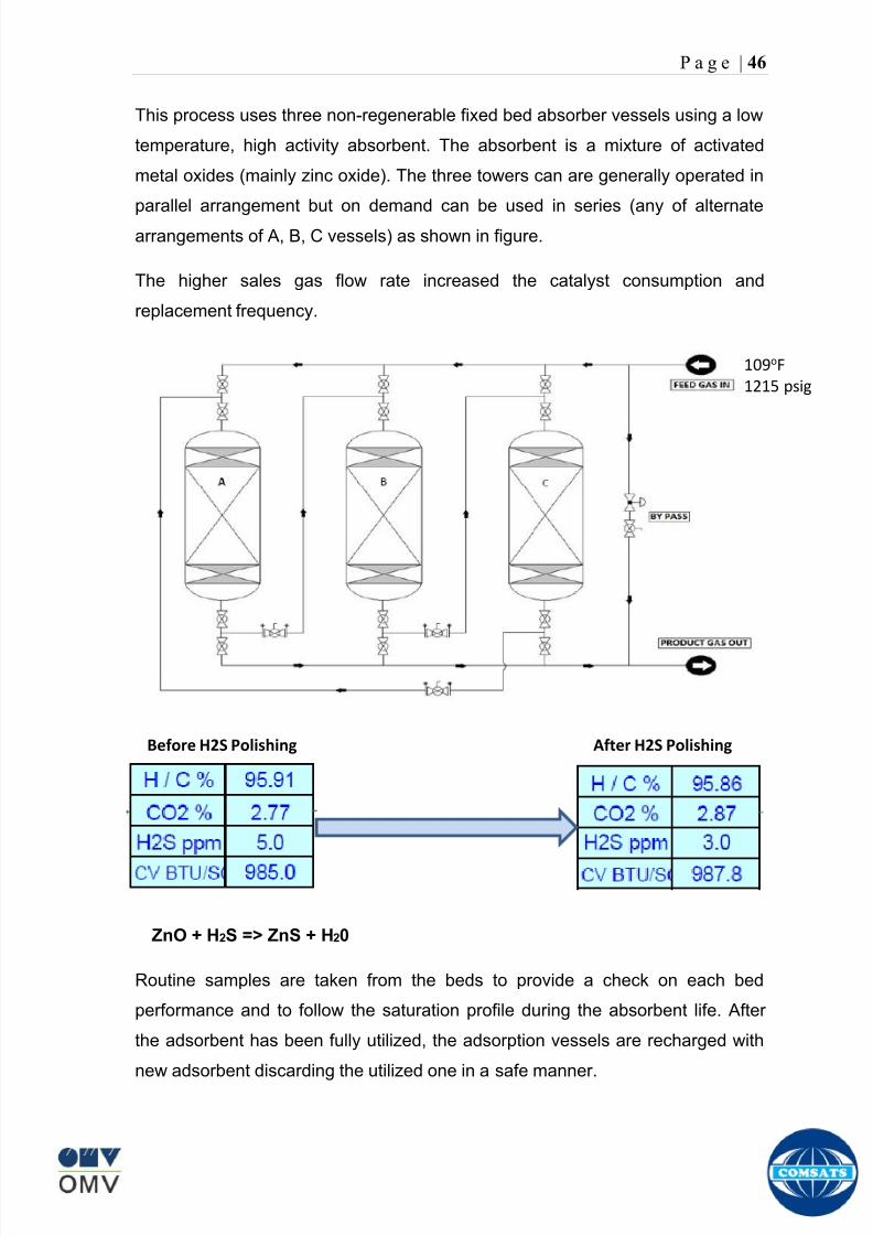
8102019 Gas sweetening Plant
httpslidepdfcomreaderfullgas-sweetening-plant 5062
P a g e | 46
This process uses three non-regenerable fixed bed absorber vessels using a low
temperature high activity absorbent The absorbent is a mixture of activated
metal oxides (mainly zinc oxide) The three towers can are generally operated in
parallel arrangement but on demand can be used in series (any of alternate
arrangements of A B C vessels) as shown in figure
The higher sales gas flow rate increased the catalyst consumption and
replacement frequency
ZnO + H2S =gt ZnS + H20
Routine samples are taken from the beds to provide a check on each bed
performance and to follow the saturation profile during the absorbent life After
the adsorbent has been fully utilized the adsorption vessels are recharged with
new adsorbent discarding the utilized one in a safe manner
109oF
1215 psig
Before H2S Polishing After H2S Polishing
8102019 Gas sweetening Plant
httpslidepdfcomreaderfullgas-sweetening-plant 5162
P a g e | 47
Figure
H2S Tower
Inlet pipe
4 Drums of 19mm
ceramic Balls
6 Micron mesh
5 Drums of 50mmceramic
1 Drums of19mm ceramic
01 Drums of6mm ceramic
112 drums of
Catalist ZnO
8102019 Gas sweetening Plant
httpslidepdfcomreaderfullgas-sweetening-plant 5262
P a g e | 48
Recycle Compressor
The permeate gas of the primary membrane unit carries recoverable amount of
CH4 It is fed to recycle membrane unit for further CH 4 recovery But the
permeate pressure from primary membranes which has been reduced to 12 psi
must be regenerated to 1200 psi for the gas to be fed again to the system For
this purpose we have employed recycle compressor The compressor is a four
stage centrifugal compressor It is driven by gas turbine of 31200 HP It has 25
MW producing capacity
Figure Recycle Compressor Process Flow Diagram
8102019 Gas sweetening Plant
httpslidepdfcomreaderfullgas-sweetening-plant 5362
P a g e | 49
Sales Gas Compressor
Gas from H2S polishing unit is sent to sales gas compressor where its pressure
is enhanced to 1100 psi so it may be injected to SNGPL high pressure trunk line
Sales gas compressor is single stage gas turbine driven
Figure Process Flow of Sales Gas Compressor
8102019 Gas sweetening Plant
httpslidepdfcomreaderfullgas-sweetening-plant 5462
P a g e | 50
Cooling Towers
A cooling tower is a heat rejection device which extracts waste heat to theatmosphere through the cooling of a water stream to a lower temperature Hot
water from the system enters the cooling tower and is distributed over the fill
(heat transfer surface) Air is induced or forced through the fill causing a small
portion of the water to evaporate This evaporation removes heat from the
remaining water which is collected in the cold water basin and returned to the
system to absorb more heat Each cooling tower line although operating under
the same basic principle of operation is arranged a little differently
Types
Natural draft mdash Utilizes buoyancy via a tall chimney Warm moist air naturally
rises due to the density differential compared to the dry cooler outside air Warm
moist air is less dense than drier air at the same pressure This moist air
buoyancy produces an upwards current of air through the tower
Mechanical draft mdash Uses power-driven fan motors to force or draw airthrough the tower
o Induced draft mdash A mechanical draft tower with a fan at the
discharge (at the top) which pulls air up through the tower The fan
induces hot moist air out the discharge This produces low entering
and high exiting air velocities reducing the possibility of
recirculation in which discharged air flows back into the air intake
o Forced draft mdash A mechanical draft tower with a blower type fan at
the intake The fan forces air into the tower creating high entering
and low exiting air velocities The low exiting velocity is much more
susceptible to recirculation This fanfill geometry is also known as
blow-through
8102019 Gas sweetening Plant
httpslidepdfcomreaderfullgas-sweetening-plant 5562
P a g e | 51
Forced Draft Cooling Tower Vs Induced Draft Cooling Tower
Induced Draft Cooling Tower have the ability to handle large water flow
rate than Forced Draft Cooling Tower
Induced Draft Cooling Tower is suitable for large cell sizes and fan sizes
as compared with Forced Draft Larger fan size may result in greater
efficiency and consequently lower power and sound level
Forced Draft Cooling Tower can be square or rectangular type only
however Induced Draft Cooling Towers can be round square or
rectangular type
Induced Draft Cooling Tower uses more compact ground area than Forced
Draft Cooling Tower equivalent capacity due to absence of fan on one
side
Fan equipment is warm exhaust air is less liable to icing up in winter
operation (Cold Countries)
Higher velocity in Forced Draft Cooling Tower cause drop in suspension
and cause additional static resistance to system
Configuration
There are two main configurations of factory assembled cooling towers crossflow
and counterflow In crossflow cooling towers the water flows vertically down the
fill as air flows horizontally across In counterflow cooling towers the water flows
vertically down the fill as air flows vertically up
Crossflow Configuration Counterflow Configuration
8102019 Gas sweetening Plant
httpslidepdfcomreaderfullgas-sweetening-plant 5662
P a g e | 52
Drift mdash Water droplets that are carried out of the cooling tower with the exhaust
air Drift droplets have the same concentration of impurities as the water entering
the tower The drift rate is typically reduced by employing baffle-like devices
called drift eliminators through which the air must travel after leaving the fill and
spray zones of the tower
Blow-out mdash Water droplets blown out of the cooling tower by wind generally at
the air inlet openings Water may also be lost in the absence of wind through
splashing or misting Devices such as wind screens louvers splash deflectors
and water diverters are used to limit these losses
Blow-down mdash The portion of the circulating water flow that is removed (usually
discharged to a drain) in order to maintain the amount of Total Dissolved Solids
(TDS) and other impurities at an acceptably low level Higher TDS concentration
in solution may result from greater cooling tower efficiency However the higher
the TDS concentration the greater the risk of scale biological growth and
corrosion
Make-up mdash The water that must be added to the circulating water system in
order to compensate for water losses such as evaporation drift loss blow-out
blow-down etc
Approach mdash The approach is the difference in temperature between the cooled-
water temperature and the entering-air wet bulb temperature
Range mdash The range is the temperature difference between the warm water inlet
and cooled water exit
Fill mdash Inside the tower fills are added to increase contact surface as well as
contact time between air and water to provide better heat transfer The efficiency
of the tower depends on the selection and amount of fill
8102019 Gas sweetening Plant
httpslidepdfcomreaderfullgas-sweetening-plant 5762
P a g e | 53
There are two types of fills that may be used
o Film type fill (causes water to spread into a thin film)
o Splash type fill (breaks up falling stream of water and interrupts its
vertical progress)
Important
Scale build up is controlled by adding chemicals to the cooling loop and diluting
the concentration by blow down and make-up Following chemicals are added to
the Cooling to control CorrosionSale and microbial growth
Corrosion Inhibitor To control corrosion in the Cooling system
Dispersant To kept ions in suspension to avoid settle down and buildup
Sodium hypo Chlorite To Control microbial Growth
Acid To control Alkalinity in the system
High Stress Polymer To run the system at higher conductivity It is a
multifunctional polymer for Zinc amp Phosphate stabilization in cooling tower
Fin Fan Cooler
Fin fan heat exchanger is simply a pressure vessel which cools a circulating fluid
within finned tubes by forcing ambient air over the exterior of the tubes A
common example of an air cooler is a carrsquos radiator Fin Fan Coolers are used in
any application where large quantities of heat need to be transferred This
includes chemical and petrochemical industries power stations waste-to-energy
facilities as well as steelworks
Fin Fan Cooler are used for two primary reasons
They increase plant efficiency
They are a green solution as compared to cooling towers and shell and
tube heat exchangers because they do not require an auxiliary water
8102019 Gas sweetening Plant
httpslidepdfcomreaderfullgas-sweetening-plant 5862
P a g e | 54
supply (water lost due to drift and evaporation plus no water treatment
chemicals are required)
Figure General Overview of Fin Fan Cooler
Produced Water
The produced water system receives liquid from the equipment Miano slug
catcher train 1 and 2 inlet separators and is fed to three phase separator where
water oil and gas is separated The gases produced are burnt in incinerator
whereas hydrocarbon liquid is stored to be sold Liquid from compressors
recycle inlet separator recycle feed scrubber high and low pressure slug
catchers is passed to degasser Separated water is injected down the earth
Incinerator
The term incinerate means to burn something until nothing is left but ashes An
incinerator is a unit or facility used to burn trash and other types of waste until it is
reduced to ash An incinerator is constructed of heavy well-insulated materials
so that it does not give off extreme amounts of external heat The high levels of
heat are kept inside the furnace or unit so that the waste is burned quickly and
efficiently If the heat were allowed to escape the waste would not burn as
completely or as rapidly
8102019 Gas sweetening Plant
httpslidepdfcomreaderfullgas-sweetening-plant 5962
P a g e | 55
Control System
The plant is controlled at CCR (Central Control Room) by PLCs (Programmable
Logic Controllers) through fiber optic control line All control parameters are
received at LER (Local Equipment Room) via two optic fiber control lines One
being primary and other secondary operating in redundancy ie if primary fails
control shifts to secondary These control parameters are sent to CCR via single
optic fiber cable
Safety System
Wellheads and Gas Processing Plant have their own Fire amp Gas detection
systems emergency shutdown (ESD) Plant has a fault tolerant controller It is
based on Triple Modular Redundant (TMR) architecture manufactured by
Triconex The TMR system is based on three isolated parallel control systems
integrated into one system The system operates on a two out of three voting
principle which provides high integrity error free uninterrupted operation with no
single point of failure The TMR receives inputs from Process Sensors Manual
Switches Fire amp Gas Detectors Packaged Equipment Control Systems and
Product Exporting Facilities The TMR carries out cause and effect processing on
the data received and where necessary produces output signals Outputs from
the TMR are hard wired directly to ESD shutdown and blow down valve
solenoids motor control instrumentelectrical interfaces to control electrical
drives package equipment logic control systems manifold area as well as
telecoms
The operator in central control room is able to accept alarms and once the fault
has been cleared reset the input All the control systems are centralized to a
single interface All the PLCs (Programmable Logic Controllers) communicate with
the servers and servers communicate with the clients through Ethernet connectivity
Centralization eases the navigation of different systems at a common interface
Emergency Shutdown
The ESD system receives inputs from field mounted instrumentation on the process
8102019 Gas sweetening Plant
httpslidepdfcomreaderfullgas-sweetening-plant 6062
P a g e | 56
and utility equipment and initiates executive actions appropriate to the level of ESD
The system is an Active system which is in standby and will activate when in an
alarm or fault condition The Kadanwari Gas Process Facility ESD system is
comprised of five (5) levels The emergency severity decreases with increasing ESD
level number
ESD 1
This shutdown level is automatically initiated by fire major gas leak or a detected
toxic atmosphere in the process area of the plant or manually from CCR A level 1
shutdown will cause all production to cease close all emergency shutdown
valves stop the process and shutdown of the main power generation The
emergency vent valves to the stack will open and in addition all equipment of zone 1
certified will be isolated This is the highest level of ESD and will cause the following
to occur
All Shutdown Valves (SDVs) on the process facility will close All slowdown Valves (BDVs) on the process facility will open
All Main Gas Driven Generators will be tripped
Emergency Diesel Generator will start
All electrical power to process and utility rotating equipment will be
isolated
Wellhead Choke Valves Close Wing Valves Close Upper Master Valve
(UMV) Close
ESD 2
This shutdown level is activated automatically if a major process or utility failure
occurs or manually from CCR All production to the plant from the wellhead is
stopped All emergency shutdown valves trip to their fail safe position
Venting shall be as specified This level of ESD will cause the following to occur
8102019 Gas sweetening Plant
httpslidepdfcomreaderfullgas-sweetening-plant 6162
P a g e | 57
All Shutdown Valves (SDVs) on the process facility will close
All electrical power to process and utility rotating equipment will be
isolated
Wellhead Choke Valve Close Wing Valves Close and Upper Master Valve(UMV) Close
ESD 3
The level 3 shutdown isolates and stops a single process train only Production
continues via the other train This ESD level is initiated by process conditions or
operator at local panel This level of ESD will cause the following to occur
ESD 3A Train 1 production to cease
ESD 3B Train 2 production to cease
All online wellhead choke valves go to minimum flow ie (1O )
ESD 4
A level 4 shutdown shall cease all production from an entire field either
Kadanwari or Miano upstream of the associated slug catchers ESD 4K for
Kadanwari amp ESD 4M for Miano This ESD level is initiated automatically by slug
catcher abnormal process conditions This level of ESD will cause the following
to occur
All SDVs close isolating the relevant slug catcher and its upstream gas
production facility from the Kadanwari Gas Processing Plant
All Wellhead Choke Valves Close Wing Valves Close and Upper MasterValves (UMV) of the relevant gas production facility Close
A parallel timer is provided to close within 10 second if not closed in given
time SSSV seals the well
ESD 5
A level 5 shutdown represents equipment shutdown for the protection of the
individual equipment without any change in the process This level of ESD is for the
protection of various pieces of equipment and is initiated by its own inputs eg
8102019 Gas sweetening Plant
httpslidepdfcomreaderfullgas-sweetening-plant 6262
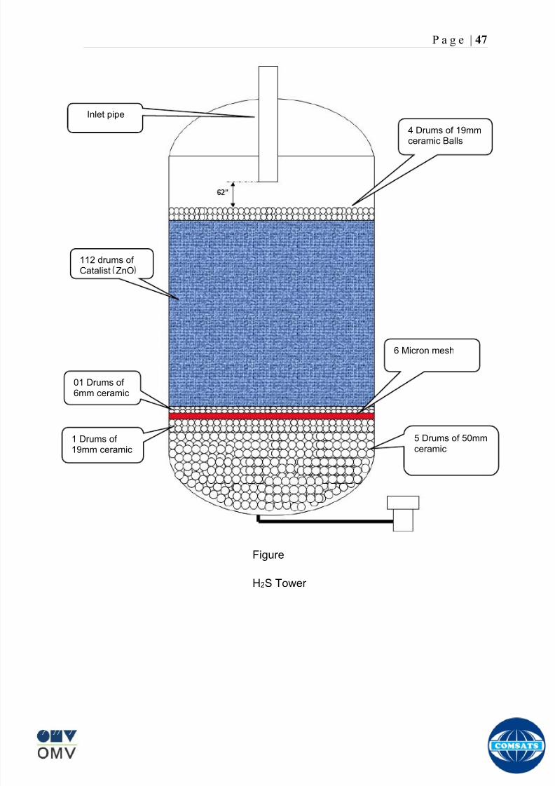
8102019 Gas sweetening Plant
httpslidepdfcomreaderfullgas-sweetening-plant 5162
P a g e | 47
Figure
H2S Tower
Inlet pipe
4 Drums of 19mm
ceramic Balls
6 Micron mesh
5 Drums of 50mmceramic
1 Drums of19mm ceramic
01 Drums of6mm ceramic
112 drums of
Catalist ZnO
8102019 Gas sweetening Plant
httpslidepdfcomreaderfullgas-sweetening-plant 5262
P a g e | 48
Recycle Compressor
The permeate gas of the primary membrane unit carries recoverable amount of
CH4 It is fed to recycle membrane unit for further CH 4 recovery But the
permeate pressure from primary membranes which has been reduced to 12 psi
must be regenerated to 1200 psi for the gas to be fed again to the system For
this purpose we have employed recycle compressor The compressor is a four
stage centrifugal compressor It is driven by gas turbine of 31200 HP It has 25
MW producing capacity
Figure Recycle Compressor Process Flow Diagram
8102019 Gas sweetening Plant
httpslidepdfcomreaderfullgas-sweetening-plant 5362
P a g e | 49
Sales Gas Compressor
Gas from H2S polishing unit is sent to sales gas compressor where its pressure
is enhanced to 1100 psi so it may be injected to SNGPL high pressure trunk line
Sales gas compressor is single stage gas turbine driven
Figure Process Flow of Sales Gas Compressor
8102019 Gas sweetening Plant
httpslidepdfcomreaderfullgas-sweetening-plant 5462
P a g e | 50
Cooling Towers
A cooling tower is a heat rejection device which extracts waste heat to theatmosphere through the cooling of a water stream to a lower temperature Hot
water from the system enters the cooling tower and is distributed over the fill
(heat transfer surface) Air is induced or forced through the fill causing a small
portion of the water to evaporate This evaporation removes heat from the
remaining water which is collected in the cold water basin and returned to the
system to absorb more heat Each cooling tower line although operating under
the same basic principle of operation is arranged a little differently
Types
Natural draft mdash Utilizes buoyancy via a tall chimney Warm moist air naturally
rises due to the density differential compared to the dry cooler outside air Warm
moist air is less dense than drier air at the same pressure This moist air
buoyancy produces an upwards current of air through the tower
Mechanical draft mdash Uses power-driven fan motors to force or draw airthrough the tower
o Induced draft mdash A mechanical draft tower with a fan at the
discharge (at the top) which pulls air up through the tower The fan
induces hot moist air out the discharge This produces low entering
and high exiting air velocities reducing the possibility of
recirculation in which discharged air flows back into the air intake
o Forced draft mdash A mechanical draft tower with a blower type fan at
the intake The fan forces air into the tower creating high entering
and low exiting air velocities The low exiting velocity is much more
susceptible to recirculation This fanfill geometry is also known as
blow-through
8102019 Gas sweetening Plant
httpslidepdfcomreaderfullgas-sweetening-plant 5562
P a g e | 51
Forced Draft Cooling Tower Vs Induced Draft Cooling Tower
Induced Draft Cooling Tower have the ability to handle large water flow
rate than Forced Draft Cooling Tower
Induced Draft Cooling Tower is suitable for large cell sizes and fan sizes
as compared with Forced Draft Larger fan size may result in greater
efficiency and consequently lower power and sound level
Forced Draft Cooling Tower can be square or rectangular type only
however Induced Draft Cooling Towers can be round square or
rectangular type
Induced Draft Cooling Tower uses more compact ground area than Forced
Draft Cooling Tower equivalent capacity due to absence of fan on one
side
Fan equipment is warm exhaust air is less liable to icing up in winter
operation (Cold Countries)
Higher velocity in Forced Draft Cooling Tower cause drop in suspension
and cause additional static resistance to system
Configuration
There are two main configurations of factory assembled cooling towers crossflow
and counterflow In crossflow cooling towers the water flows vertically down the
fill as air flows horizontally across In counterflow cooling towers the water flows
vertically down the fill as air flows vertically up
Crossflow Configuration Counterflow Configuration
8102019 Gas sweetening Plant
httpslidepdfcomreaderfullgas-sweetening-plant 5662
P a g e | 52
Drift mdash Water droplets that are carried out of the cooling tower with the exhaust
air Drift droplets have the same concentration of impurities as the water entering
the tower The drift rate is typically reduced by employing baffle-like devices
called drift eliminators through which the air must travel after leaving the fill and
spray zones of the tower
Blow-out mdash Water droplets blown out of the cooling tower by wind generally at
the air inlet openings Water may also be lost in the absence of wind through
splashing or misting Devices such as wind screens louvers splash deflectors
and water diverters are used to limit these losses
Blow-down mdash The portion of the circulating water flow that is removed (usually
discharged to a drain) in order to maintain the amount of Total Dissolved Solids
(TDS) and other impurities at an acceptably low level Higher TDS concentration
in solution may result from greater cooling tower efficiency However the higher
the TDS concentration the greater the risk of scale biological growth and
corrosion
Make-up mdash The water that must be added to the circulating water system in
order to compensate for water losses such as evaporation drift loss blow-out
blow-down etc
Approach mdash The approach is the difference in temperature between the cooled-
water temperature and the entering-air wet bulb temperature
Range mdash The range is the temperature difference between the warm water inlet
and cooled water exit
Fill mdash Inside the tower fills are added to increase contact surface as well as
contact time between air and water to provide better heat transfer The efficiency
of the tower depends on the selection and amount of fill
8102019 Gas sweetening Plant
httpslidepdfcomreaderfullgas-sweetening-plant 5762
P a g e | 53
There are two types of fills that may be used
o Film type fill (causes water to spread into a thin film)
o Splash type fill (breaks up falling stream of water and interrupts its
vertical progress)
Important
Scale build up is controlled by adding chemicals to the cooling loop and diluting
the concentration by blow down and make-up Following chemicals are added to
the Cooling to control CorrosionSale and microbial growth
Corrosion Inhibitor To control corrosion in the Cooling system
Dispersant To kept ions in suspension to avoid settle down and buildup
Sodium hypo Chlorite To Control microbial Growth
Acid To control Alkalinity in the system
High Stress Polymer To run the system at higher conductivity It is a
multifunctional polymer for Zinc amp Phosphate stabilization in cooling tower
Fin Fan Cooler
Fin fan heat exchanger is simply a pressure vessel which cools a circulating fluid
within finned tubes by forcing ambient air over the exterior of the tubes A
common example of an air cooler is a carrsquos radiator Fin Fan Coolers are used in
any application where large quantities of heat need to be transferred This
includes chemical and petrochemical industries power stations waste-to-energy
facilities as well as steelworks
Fin Fan Cooler are used for two primary reasons
They increase plant efficiency
They are a green solution as compared to cooling towers and shell and
tube heat exchangers because they do not require an auxiliary water
8102019 Gas sweetening Plant
httpslidepdfcomreaderfullgas-sweetening-plant 5862
P a g e | 54
supply (water lost due to drift and evaporation plus no water treatment
chemicals are required)
Figure General Overview of Fin Fan Cooler
Produced Water
The produced water system receives liquid from the equipment Miano slug
catcher train 1 and 2 inlet separators and is fed to three phase separator where
water oil and gas is separated The gases produced are burnt in incinerator
whereas hydrocarbon liquid is stored to be sold Liquid from compressors
recycle inlet separator recycle feed scrubber high and low pressure slug
catchers is passed to degasser Separated water is injected down the earth
Incinerator
The term incinerate means to burn something until nothing is left but ashes An
incinerator is a unit or facility used to burn trash and other types of waste until it is
reduced to ash An incinerator is constructed of heavy well-insulated materials
so that it does not give off extreme amounts of external heat The high levels of
heat are kept inside the furnace or unit so that the waste is burned quickly and
efficiently If the heat were allowed to escape the waste would not burn as
completely or as rapidly
8102019 Gas sweetening Plant
httpslidepdfcomreaderfullgas-sweetening-plant 5962
P a g e | 55
Control System
The plant is controlled at CCR (Central Control Room) by PLCs (Programmable
Logic Controllers) through fiber optic control line All control parameters are
received at LER (Local Equipment Room) via two optic fiber control lines One
being primary and other secondary operating in redundancy ie if primary fails
control shifts to secondary These control parameters are sent to CCR via single
optic fiber cable
Safety System
Wellheads and Gas Processing Plant have their own Fire amp Gas detection
systems emergency shutdown (ESD) Plant has a fault tolerant controller It is
based on Triple Modular Redundant (TMR) architecture manufactured by
Triconex The TMR system is based on three isolated parallel control systems
integrated into one system The system operates on a two out of three voting
principle which provides high integrity error free uninterrupted operation with no
single point of failure The TMR receives inputs from Process Sensors Manual
Switches Fire amp Gas Detectors Packaged Equipment Control Systems and
Product Exporting Facilities The TMR carries out cause and effect processing on
the data received and where necessary produces output signals Outputs from
the TMR are hard wired directly to ESD shutdown and blow down valve
solenoids motor control instrumentelectrical interfaces to control electrical
drives package equipment logic control systems manifold area as well as
telecoms
The operator in central control room is able to accept alarms and once the fault
has been cleared reset the input All the control systems are centralized to a
single interface All the PLCs (Programmable Logic Controllers) communicate with
the servers and servers communicate with the clients through Ethernet connectivity
Centralization eases the navigation of different systems at a common interface
Emergency Shutdown
The ESD system receives inputs from field mounted instrumentation on the process
8102019 Gas sweetening Plant
httpslidepdfcomreaderfullgas-sweetening-plant 6062
P a g e | 56
and utility equipment and initiates executive actions appropriate to the level of ESD
The system is an Active system which is in standby and will activate when in an
alarm or fault condition The Kadanwari Gas Process Facility ESD system is
comprised of five (5) levels The emergency severity decreases with increasing ESD
level number
ESD 1
This shutdown level is automatically initiated by fire major gas leak or a detected
toxic atmosphere in the process area of the plant or manually from CCR A level 1
shutdown will cause all production to cease close all emergency shutdown
valves stop the process and shutdown of the main power generation The
emergency vent valves to the stack will open and in addition all equipment of zone 1
certified will be isolated This is the highest level of ESD and will cause the following
to occur
All Shutdown Valves (SDVs) on the process facility will close All slowdown Valves (BDVs) on the process facility will open
All Main Gas Driven Generators will be tripped
Emergency Diesel Generator will start
All electrical power to process and utility rotating equipment will be
isolated
Wellhead Choke Valves Close Wing Valves Close Upper Master Valve
(UMV) Close
ESD 2
This shutdown level is activated automatically if a major process or utility failure
occurs or manually from CCR All production to the plant from the wellhead is
stopped All emergency shutdown valves trip to their fail safe position
Venting shall be as specified This level of ESD will cause the following to occur
8102019 Gas sweetening Plant
httpslidepdfcomreaderfullgas-sweetening-plant 6162
P a g e | 57
All Shutdown Valves (SDVs) on the process facility will close
All electrical power to process and utility rotating equipment will be
isolated
Wellhead Choke Valve Close Wing Valves Close and Upper Master Valve(UMV) Close
ESD 3
The level 3 shutdown isolates and stops a single process train only Production
continues via the other train This ESD level is initiated by process conditions or
operator at local panel This level of ESD will cause the following to occur
ESD 3A Train 1 production to cease
ESD 3B Train 2 production to cease
All online wellhead choke valves go to minimum flow ie (1O )
ESD 4
A level 4 shutdown shall cease all production from an entire field either
Kadanwari or Miano upstream of the associated slug catchers ESD 4K for
Kadanwari amp ESD 4M for Miano This ESD level is initiated automatically by slug
catcher abnormal process conditions This level of ESD will cause the following
to occur
All SDVs close isolating the relevant slug catcher and its upstream gas
production facility from the Kadanwari Gas Processing Plant
All Wellhead Choke Valves Close Wing Valves Close and Upper MasterValves (UMV) of the relevant gas production facility Close
A parallel timer is provided to close within 10 second if not closed in given
time SSSV seals the well
ESD 5
A level 5 shutdown represents equipment shutdown for the protection of the
individual equipment without any change in the process This level of ESD is for the
protection of various pieces of equipment and is initiated by its own inputs eg
8102019 Gas sweetening Plant
httpslidepdfcomreaderfullgas-sweetening-plant 6262
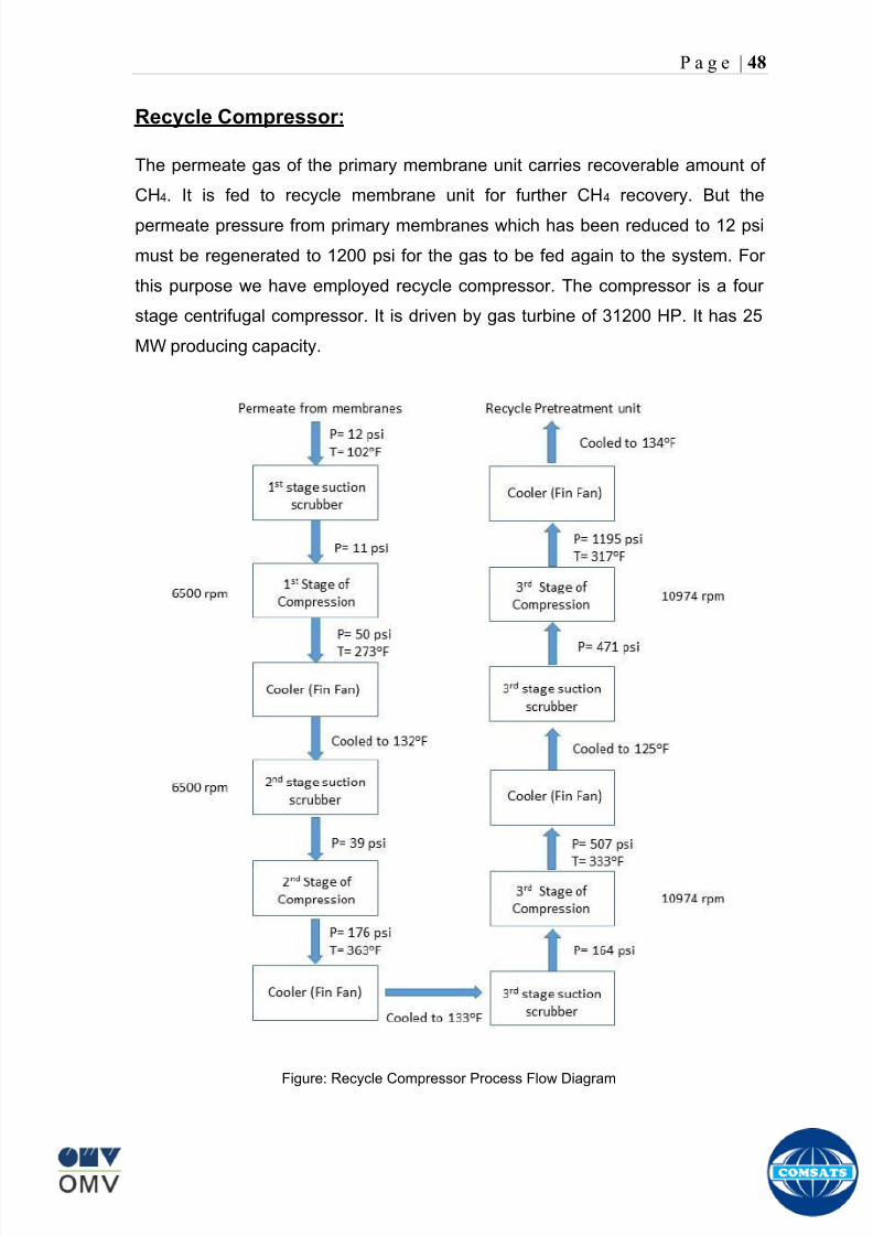
8102019 Gas sweetening Plant
httpslidepdfcomreaderfullgas-sweetening-plant 5262
P a g e | 48
Recycle Compressor
The permeate gas of the primary membrane unit carries recoverable amount of
CH4 It is fed to recycle membrane unit for further CH 4 recovery But the
permeate pressure from primary membranes which has been reduced to 12 psi
must be regenerated to 1200 psi for the gas to be fed again to the system For
this purpose we have employed recycle compressor The compressor is a four
stage centrifugal compressor It is driven by gas turbine of 31200 HP It has 25
MW producing capacity
Figure Recycle Compressor Process Flow Diagram
8102019 Gas sweetening Plant
httpslidepdfcomreaderfullgas-sweetening-plant 5362
P a g e | 49
Sales Gas Compressor
Gas from H2S polishing unit is sent to sales gas compressor where its pressure
is enhanced to 1100 psi so it may be injected to SNGPL high pressure trunk line
Sales gas compressor is single stage gas turbine driven
Figure Process Flow of Sales Gas Compressor
8102019 Gas sweetening Plant
httpslidepdfcomreaderfullgas-sweetening-plant 5462
P a g e | 50
Cooling Towers
A cooling tower is a heat rejection device which extracts waste heat to theatmosphere through the cooling of a water stream to a lower temperature Hot
water from the system enters the cooling tower and is distributed over the fill
(heat transfer surface) Air is induced or forced through the fill causing a small
portion of the water to evaporate This evaporation removes heat from the
remaining water which is collected in the cold water basin and returned to the
system to absorb more heat Each cooling tower line although operating under
the same basic principle of operation is arranged a little differently
Types
Natural draft mdash Utilizes buoyancy via a tall chimney Warm moist air naturally
rises due to the density differential compared to the dry cooler outside air Warm
moist air is less dense than drier air at the same pressure This moist air
buoyancy produces an upwards current of air through the tower
Mechanical draft mdash Uses power-driven fan motors to force or draw airthrough the tower
o Induced draft mdash A mechanical draft tower with a fan at the
discharge (at the top) which pulls air up through the tower The fan
induces hot moist air out the discharge This produces low entering
and high exiting air velocities reducing the possibility of
recirculation in which discharged air flows back into the air intake
o Forced draft mdash A mechanical draft tower with a blower type fan at
the intake The fan forces air into the tower creating high entering
and low exiting air velocities The low exiting velocity is much more
susceptible to recirculation This fanfill geometry is also known as
blow-through
8102019 Gas sweetening Plant
httpslidepdfcomreaderfullgas-sweetening-plant 5562
P a g e | 51
Forced Draft Cooling Tower Vs Induced Draft Cooling Tower
Induced Draft Cooling Tower have the ability to handle large water flow
rate than Forced Draft Cooling Tower
Induced Draft Cooling Tower is suitable for large cell sizes and fan sizes
as compared with Forced Draft Larger fan size may result in greater
efficiency and consequently lower power and sound level
Forced Draft Cooling Tower can be square or rectangular type only
however Induced Draft Cooling Towers can be round square or
rectangular type
Induced Draft Cooling Tower uses more compact ground area than Forced
Draft Cooling Tower equivalent capacity due to absence of fan on one
side
Fan equipment is warm exhaust air is less liable to icing up in winter
operation (Cold Countries)
Higher velocity in Forced Draft Cooling Tower cause drop in suspension
and cause additional static resistance to system
Configuration
There are two main configurations of factory assembled cooling towers crossflow
and counterflow In crossflow cooling towers the water flows vertically down the
fill as air flows horizontally across In counterflow cooling towers the water flows
vertically down the fill as air flows vertically up
Crossflow Configuration Counterflow Configuration
8102019 Gas sweetening Plant
httpslidepdfcomreaderfullgas-sweetening-plant 5662
P a g e | 52
Drift mdash Water droplets that are carried out of the cooling tower with the exhaust
air Drift droplets have the same concentration of impurities as the water entering
the tower The drift rate is typically reduced by employing baffle-like devices
called drift eliminators through which the air must travel after leaving the fill and
spray zones of the tower
Blow-out mdash Water droplets blown out of the cooling tower by wind generally at
the air inlet openings Water may also be lost in the absence of wind through
splashing or misting Devices such as wind screens louvers splash deflectors
and water diverters are used to limit these losses
Blow-down mdash The portion of the circulating water flow that is removed (usually
discharged to a drain) in order to maintain the amount of Total Dissolved Solids
(TDS) and other impurities at an acceptably low level Higher TDS concentration
in solution may result from greater cooling tower efficiency However the higher
the TDS concentration the greater the risk of scale biological growth and
corrosion
Make-up mdash The water that must be added to the circulating water system in
order to compensate for water losses such as evaporation drift loss blow-out
blow-down etc
Approach mdash The approach is the difference in temperature between the cooled-
water temperature and the entering-air wet bulb temperature
Range mdash The range is the temperature difference between the warm water inlet
and cooled water exit
Fill mdash Inside the tower fills are added to increase contact surface as well as
contact time between air and water to provide better heat transfer The efficiency
of the tower depends on the selection and amount of fill
8102019 Gas sweetening Plant
httpslidepdfcomreaderfullgas-sweetening-plant 5762
P a g e | 53
There are two types of fills that may be used
o Film type fill (causes water to spread into a thin film)
o Splash type fill (breaks up falling stream of water and interrupts its
vertical progress)
Important
Scale build up is controlled by adding chemicals to the cooling loop and diluting
the concentration by blow down and make-up Following chemicals are added to
the Cooling to control CorrosionSale and microbial growth
Corrosion Inhibitor To control corrosion in the Cooling system
Dispersant To kept ions in suspension to avoid settle down and buildup
Sodium hypo Chlorite To Control microbial Growth
Acid To control Alkalinity in the system
High Stress Polymer To run the system at higher conductivity It is a
multifunctional polymer for Zinc amp Phosphate stabilization in cooling tower
Fin Fan Cooler
Fin fan heat exchanger is simply a pressure vessel which cools a circulating fluid
within finned tubes by forcing ambient air over the exterior of the tubes A
common example of an air cooler is a carrsquos radiator Fin Fan Coolers are used in
any application where large quantities of heat need to be transferred This
includes chemical and petrochemical industries power stations waste-to-energy
facilities as well as steelworks
Fin Fan Cooler are used for two primary reasons
They increase plant efficiency
They are a green solution as compared to cooling towers and shell and
tube heat exchangers because they do not require an auxiliary water
8102019 Gas sweetening Plant
httpslidepdfcomreaderfullgas-sweetening-plant 5862
P a g e | 54
supply (water lost due to drift and evaporation plus no water treatment
chemicals are required)
Figure General Overview of Fin Fan Cooler
Produced Water
The produced water system receives liquid from the equipment Miano slug
catcher train 1 and 2 inlet separators and is fed to three phase separator where
water oil and gas is separated The gases produced are burnt in incinerator
whereas hydrocarbon liquid is stored to be sold Liquid from compressors
recycle inlet separator recycle feed scrubber high and low pressure slug
catchers is passed to degasser Separated water is injected down the earth
Incinerator
The term incinerate means to burn something until nothing is left but ashes An
incinerator is a unit or facility used to burn trash and other types of waste until it is
reduced to ash An incinerator is constructed of heavy well-insulated materials
so that it does not give off extreme amounts of external heat The high levels of
heat are kept inside the furnace or unit so that the waste is burned quickly and
efficiently If the heat were allowed to escape the waste would not burn as
completely or as rapidly
8102019 Gas sweetening Plant
httpslidepdfcomreaderfullgas-sweetening-plant 5962
P a g e | 55
Control System
The plant is controlled at CCR (Central Control Room) by PLCs (Programmable
Logic Controllers) through fiber optic control line All control parameters are
received at LER (Local Equipment Room) via two optic fiber control lines One
being primary and other secondary operating in redundancy ie if primary fails
control shifts to secondary These control parameters are sent to CCR via single
optic fiber cable
Safety System
Wellheads and Gas Processing Plant have their own Fire amp Gas detection
systems emergency shutdown (ESD) Plant has a fault tolerant controller It is
based on Triple Modular Redundant (TMR) architecture manufactured by
Triconex The TMR system is based on three isolated parallel control systems
integrated into one system The system operates on a two out of three voting
principle which provides high integrity error free uninterrupted operation with no
single point of failure The TMR receives inputs from Process Sensors Manual
Switches Fire amp Gas Detectors Packaged Equipment Control Systems and
Product Exporting Facilities The TMR carries out cause and effect processing on
the data received and where necessary produces output signals Outputs from
the TMR are hard wired directly to ESD shutdown and blow down valve
solenoids motor control instrumentelectrical interfaces to control electrical
drives package equipment logic control systems manifold area as well as
telecoms
The operator in central control room is able to accept alarms and once the fault
has been cleared reset the input All the control systems are centralized to a
single interface All the PLCs (Programmable Logic Controllers) communicate with
the servers and servers communicate with the clients through Ethernet connectivity
Centralization eases the navigation of different systems at a common interface
Emergency Shutdown
The ESD system receives inputs from field mounted instrumentation on the process
8102019 Gas sweetening Plant
httpslidepdfcomreaderfullgas-sweetening-plant 6062
P a g e | 56
and utility equipment and initiates executive actions appropriate to the level of ESD
The system is an Active system which is in standby and will activate when in an
alarm or fault condition The Kadanwari Gas Process Facility ESD system is
comprised of five (5) levels The emergency severity decreases with increasing ESD
level number
ESD 1
This shutdown level is automatically initiated by fire major gas leak or a detected
toxic atmosphere in the process area of the plant or manually from CCR A level 1
shutdown will cause all production to cease close all emergency shutdown
valves stop the process and shutdown of the main power generation The
emergency vent valves to the stack will open and in addition all equipment of zone 1
certified will be isolated This is the highest level of ESD and will cause the following
to occur
All Shutdown Valves (SDVs) on the process facility will close All slowdown Valves (BDVs) on the process facility will open
All Main Gas Driven Generators will be tripped
Emergency Diesel Generator will start
All electrical power to process and utility rotating equipment will be
isolated
Wellhead Choke Valves Close Wing Valves Close Upper Master Valve
(UMV) Close
ESD 2
This shutdown level is activated automatically if a major process or utility failure
occurs or manually from CCR All production to the plant from the wellhead is
stopped All emergency shutdown valves trip to their fail safe position
Venting shall be as specified This level of ESD will cause the following to occur
8102019 Gas sweetening Plant
httpslidepdfcomreaderfullgas-sweetening-plant 6162
P a g e | 57
All Shutdown Valves (SDVs) on the process facility will close
All electrical power to process and utility rotating equipment will be
isolated
Wellhead Choke Valve Close Wing Valves Close and Upper Master Valve(UMV) Close
ESD 3
The level 3 shutdown isolates and stops a single process train only Production
continues via the other train This ESD level is initiated by process conditions or
operator at local panel This level of ESD will cause the following to occur
ESD 3A Train 1 production to cease
ESD 3B Train 2 production to cease
All online wellhead choke valves go to minimum flow ie (1O )
ESD 4
A level 4 shutdown shall cease all production from an entire field either
Kadanwari or Miano upstream of the associated slug catchers ESD 4K for
Kadanwari amp ESD 4M for Miano This ESD level is initiated automatically by slug
catcher abnormal process conditions This level of ESD will cause the following
to occur
All SDVs close isolating the relevant slug catcher and its upstream gas
production facility from the Kadanwari Gas Processing Plant
All Wellhead Choke Valves Close Wing Valves Close and Upper MasterValves (UMV) of the relevant gas production facility Close
A parallel timer is provided to close within 10 second if not closed in given
time SSSV seals the well
ESD 5
A level 5 shutdown represents equipment shutdown for the protection of the
individual equipment without any change in the process This level of ESD is for the
protection of various pieces of equipment and is initiated by its own inputs eg
8102019 Gas sweetening Plant
httpslidepdfcomreaderfullgas-sweetening-plant 6262
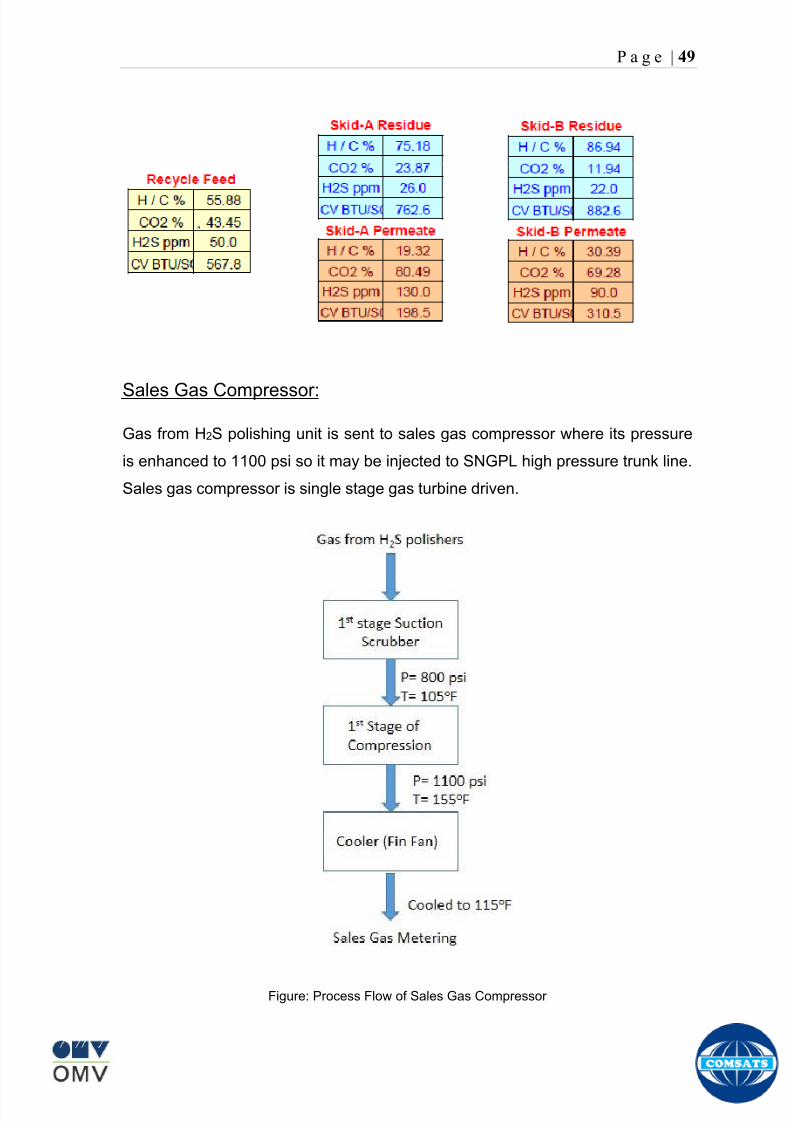
8102019 Gas sweetening Plant
httpslidepdfcomreaderfullgas-sweetening-plant 5362
P a g e | 49
Sales Gas Compressor
Gas from H2S polishing unit is sent to sales gas compressor where its pressure
is enhanced to 1100 psi so it may be injected to SNGPL high pressure trunk line
Sales gas compressor is single stage gas turbine driven
Figure Process Flow of Sales Gas Compressor
8102019 Gas sweetening Plant
httpslidepdfcomreaderfullgas-sweetening-plant 5462
P a g e | 50
Cooling Towers
A cooling tower is a heat rejection device which extracts waste heat to theatmosphere through the cooling of a water stream to a lower temperature Hot
water from the system enters the cooling tower and is distributed over the fill
(heat transfer surface) Air is induced or forced through the fill causing a small
portion of the water to evaporate This evaporation removes heat from the
remaining water which is collected in the cold water basin and returned to the
system to absorb more heat Each cooling tower line although operating under
the same basic principle of operation is arranged a little differently
Types
Natural draft mdash Utilizes buoyancy via a tall chimney Warm moist air naturally
rises due to the density differential compared to the dry cooler outside air Warm
moist air is less dense than drier air at the same pressure This moist air
buoyancy produces an upwards current of air through the tower
Mechanical draft mdash Uses power-driven fan motors to force or draw airthrough the tower
o Induced draft mdash A mechanical draft tower with a fan at the
discharge (at the top) which pulls air up through the tower The fan
induces hot moist air out the discharge This produces low entering
and high exiting air velocities reducing the possibility of
recirculation in which discharged air flows back into the air intake
o Forced draft mdash A mechanical draft tower with a blower type fan at
the intake The fan forces air into the tower creating high entering
and low exiting air velocities The low exiting velocity is much more
susceptible to recirculation This fanfill geometry is also known as
blow-through
8102019 Gas sweetening Plant
httpslidepdfcomreaderfullgas-sweetening-plant 5562
P a g e | 51
Forced Draft Cooling Tower Vs Induced Draft Cooling Tower
Induced Draft Cooling Tower have the ability to handle large water flow
rate than Forced Draft Cooling Tower
Induced Draft Cooling Tower is suitable for large cell sizes and fan sizes
as compared with Forced Draft Larger fan size may result in greater
efficiency and consequently lower power and sound level
Forced Draft Cooling Tower can be square or rectangular type only
however Induced Draft Cooling Towers can be round square or
rectangular type
Induced Draft Cooling Tower uses more compact ground area than Forced
Draft Cooling Tower equivalent capacity due to absence of fan on one
side
Fan equipment is warm exhaust air is less liable to icing up in winter
operation (Cold Countries)
Higher velocity in Forced Draft Cooling Tower cause drop in suspension
and cause additional static resistance to system
Configuration
There are two main configurations of factory assembled cooling towers crossflow
and counterflow In crossflow cooling towers the water flows vertically down the
fill as air flows horizontally across In counterflow cooling towers the water flows
vertically down the fill as air flows vertically up
Crossflow Configuration Counterflow Configuration
8102019 Gas sweetening Plant
httpslidepdfcomreaderfullgas-sweetening-plant 5662
P a g e | 52
Drift mdash Water droplets that are carried out of the cooling tower with the exhaust
air Drift droplets have the same concentration of impurities as the water entering
the tower The drift rate is typically reduced by employing baffle-like devices
called drift eliminators through which the air must travel after leaving the fill and
spray zones of the tower
Blow-out mdash Water droplets blown out of the cooling tower by wind generally at
the air inlet openings Water may also be lost in the absence of wind through
splashing or misting Devices such as wind screens louvers splash deflectors
and water diverters are used to limit these losses
Blow-down mdash The portion of the circulating water flow that is removed (usually
discharged to a drain) in order to maintain the amount of Total Dissolved Solids
(TDS) and other impurities at an acceptably low level Higher TDS concentration
in solution may result from greater cooling tower efficiency However the higher
the TDS concentration the greater the risk of scale biological growth and
corrosion
Make-up mdash The water that must be added to the circulating water system in
order to compensate for water losses such as evaporation drift loss blow-out
blow-down etc
Approach mdash The approach is the difference in temperature between the cooled-
water temperature and the entering-air wet bulb temperature
Range mdash The range is the temperature difference between the warm water inlet
and cooled water exit
Fill mdash Inside the tower fills are added to increase contact surface as well as
contact time between air and water to provide better heat transfer The efficiency
of the tower depends on the selection and amount of fill
8102019 Gas sweetening Plant
httpslidepdfcomreaderfullgas-sweetening-plant 5762
P a g e | 53
There are two types of fills that may be used
o Film type fill (causes water to spread into a thin film)
o Splash type fill (breaks up falling stream of water and interrupts its
vertical progress)
Important
Scale build up is controlled by adding chemicals to the cooling loop and diluting
the concentration by blow down and make-up Following chemicals are added to
the Cooling to control CorrosionSale and microbial growth
Corrosion Inhibitor To control corrosion in the Cooling system
Dispersant To kept ions in suspension to avoid settle down and buildup
Sodium hypo Chlorite To Control microbial Growth
Acid To control Alkalinity in the system
High Stress Polymer To run the system at higher conductivity It is a
multifunctional polymer for Zinc amp Phosphate stabilization in cooling tower
Fin Fan Cooler
Fin fan heat exchanger is simply a pressure vessel which cools a circulating fluid
within finned tubes by forcing ambient air over the exterior of the tubes A
common example of an air cooler is a carrsquos radiator Fin Fan Coolers are used in
any application where large quantities of heat need to be transferred This
includes chemical and petrochemical industries power stations waste-to-energy
facilities as well as steelworks
Fin Fan Cooler are used for two primary reasons
They increase plant efficiency
They are a green solution as compared to cooling towers and shell and
tube heat exchangers because they do not require an auxiliary water
8102019 Gas sweetening Plant
httpslidepdfcomreaderfullgas-sweetening-plant 5862
P a g e | 54
supply (water lost due to drift and evaporation plus no water treatment
chemicals are required)
Figure General Overview of Fin Fan Cooler
Produced Water
The produced water system receives liquid from the equipment Miano slug
catcher train 1 and 2 inlet separators and is fed to three phase separator where
water oil and gas is separated The gases produced are burnt in incinerator
whereas hydrocarbon liquid is stored to be sold Liquid from compressors
recycle inlet separator recycle feed scrubber high and low pressure slug
catchers is passed to degasser Separated water is injected down the earth
Incinerator
The term incinerate means to burn something until nothing is left but ashes An
incinerator is a unit or facility used to burn trash and other types of waste until it is
reduced to ash An incinerator is constructed of heavy well-insulated materials
so that it does not give off extreme amounts of external heat The high levels of
heat are kept inside the furnace or unit so that the waste is burned quickly and
efficiently If the heat were allowed to escape the waste would not burn as
completely or as rapidly
8102019 Gas sweetening Plant
httpslidepdfcomreaderfullgas-sweetening-plant 5962
P a g e | 55
Control System
The plant is controlled at CCR (Central Control Room) by PLCs (Programmable
Logic Controllers) through fiber optic control line All control parameters are
received at LER (Local Equipment Room) via two optic fiber control lines One
being primary and other secondary operating in redundancy ie if primary fails
control shifts to secondary These control parameters are sent to CCR via single
optic fiber cable
Safety System
Wellheads and Gas Processing Plant have their own Fire amp Gas detection
systems emergency shutdown (ESD) Plant has a fault tolerant controller It is
based on Triple Modular Redundant (TMR) architecture manufactured by
Triconex The TMR system is based on three isolated parallel control systems
integrated into one system The system operates on a two out of three voting
principle which provides high integrity error free uninterrupted operation with no
single point of failure The TMR receives inputs from Process Sensors Manual
Switches Fire amp Gas Detectors Packaged Equipment Control Systems and
Product Exporting Facilities The TMR carries out cause and effect processing on
the data received and where necessary produces output signals Outputs from
the TMR are hard wired directly to ESD shutdown and blow down valve
solenoids motor control instrumentelectrical interfaces to control electrical
drives package equipment logic control systems manifold area as well as
telecoms
The operator in central control room is able to accept alarms and once the fault
has been cleared reset the input All the control systems are centralized to a
single interface All the PLCs (Programmable Logic Controllers) communicate with
the servers and servers communicate with the clients through Ethernet connectivity
Centralization eases the navigation of different systems at a common interface
Emergency Shutdown
The ESD system receives inputs from field mounted instrumentation on the process
8102019 Gas sweetening Plant
httpslidepdfcomreaderfullgas-sweetening-plant 6062
P a g e | 56
and utility equipment and initiates executive actions appropriate to the level of ESD
The system is an Active system which is in standby and will activate when in an
alarm or fault condition The Kadanwari Gas Process Facility ESD system is
comprised of five (5) levels The emergency severity decreases with increasing ESD
level number
ESD 1
This shutdown level is automatically initiated by fire major gas leak or a detected
toxic atmosphere in the process area of the plant or manually from CCR A level 1
shutdown will cause all production to cease close all emergency shutdown
valves stop the process and shutdown of the main power generation The
emergency vent valves to the stack will open and in addition all equipment of zone 1
certified will be isolated This is the highest level of ESD and will cause the following
to occur
All Shutdown Valves (SDVs) on the process facility will close All slowdown Valves (BDVs) on the process facility will open
All Main Gas Driven Generators will be tripped
Emergency Diesel Generator will start
All electrical power to process and utility rotating equipment will be
isolated
Wellhead Choke Valves Close Wing Valves Close Upper Master Valve
(UMV) Close
ESD 2
This shutdown level is activated automatically if a major process or utility failure
occurs or manually from CCR All production to the plant from the wellhead is
stopped All emergency shutdown valves trip to their fail safe position
Venting shall be as specified This level of ESD will cause the following to occur
8102019 Gas sweetening Plant
httpslidepdfcomreaderfullgas-sweetening-plant 6162
P a g e | 57
All Shutdown Valves (SDVs) on the process facility will close
All electrical power to process and utility rotating equipment will be
isolated
Wellhead Choke Valve Close Wing Valves Close and Upper Master Valve(UMV) Close
ESD 3
The level 3 shutdown isolates and stops a single process train only Production
continues via the other train This ESD level is initiated by process conditions or
operator at local panel This level of ESD will cause the following to occur
ESD 3A Train 1 production to cease
ESD 3B Train 2 production to cease
All online wellhead choke valves go to minimum flow ie (1O )
ESD 4
A level 4 shutdown shall cease all production from an entire field either
Kadanwari or Miano upstream of the associated slug catchers ESD 4K for
Kadanwari amp ESD 4M for Miano This ESD level is initiated automatically by slug
catcher abnormal process conditions This level of ESD will cause the following
to occur
All SDVs close isolating the relevant slug catcher and its upstream gas
production facility from the Kadanwari Gas Processing Plant
All Wellhead Choke Valves Close Wing Valves Close and Upper MasterValves (UMV) of the relevant gas production facility Close
A parallel timer is provided to close within 10 second if not closed in given
time SSSV seals the well
ESD 5
A level 5 shutdown represents equipment shutdown for the protection of the
individual equipment without any change in the process This level of ESD is for the
protection of various pieces of equipment and is initiated by its own inputs eg
8102019 Gas sweetening Plant
httpslidepdfcomreaderfullgas-sweetening-plant 6262
8102019 Gas sweetening Plant
httpslidepdfcomreaderfullgas-sweetening-plant 5462
P a g e | 50
Cooling Towers
A cooling tower is a heat rejection device which extracts waste heat to theatmosphere through the cooling of a water stream to a lower temperature Hot
water from the system enters the cooling tower and is distributed over the fill
(heat transfer surface) Air is induced or forced through the fill causing a small
portion of the water to evaporate This evaporation removes heat from the
remaining water which is collected in the cold water basin and returned to the
system to absorb more heat Each cooling tower line although operating under
the same basic principle of operation is arranged a little differently
Types
Natural draft mdash Utilizes buoyancy via a tall chimney Warm moist air naturally
rises due to the density differential compared to the dry cooler outside air Warm
moist air is less dense than drier air at the same pressure This moist air
buoyancy produces an upwards current of air through the tower
Mechanical draft mdash Uses power-driven fan motors to force or draw airthrough the tower
o Induced draft mdash A mechanical draft tower with a fan at the
discharge (at the top) which pulls air up through the tower The fan
induces hot moist air out the discharge This produces low entering
and high exiting air velocities reducing the possibility of
recirculation in which discharged air flows back into the air intake
o Forced draft mdash A mechanical draft tower with a blower type fan at
the intake The fan forces air into the tower creating high entering
and low exiting air velocities The low exiting velocity is much more
susceptible to recirculation This fanfill geometry is also known as
blow-through
8102019 Gas sweetening Plant
httpslidepdfcomreaderfullgas-sweetening-plant 5562
P a g e | 51
Forced Draft Cooling Tower Vs Induced Draft Cooling Tower
Induced Draft Cooling Tower have the ability to handle large water flow
rate than Forced Draft Cooling Tower
Induced Draft Cooling Tower is suitable for large cell sizes and fan sizes
as compared with Forced Draft Larger fan size may result in greater
efficiency and consequently lower power and sound level
Forced Draft Cooling Tower can be square or rectangular type only
however Induced Draft Cooling Towers can be round square or
rectangular type
Induced Draft Cooling Tower uses more compact ground area than Forced
Draft Cooling Tower equivalent capacity due to absence of fan on one
side
Fan equipment is warm exhaust air is less liable to icing up in winter
operation (Cold Countries)
Higher velocity in Forced Draft Cooling Tower cause drop in suspension
and cause additional static resistance to system
Configuration
There are two main configurations of factory assembled cooling towers crossflow
and counterflow In crossflow cooling towers the water flows vertically down the
fill as air flows horizontally across In counterflow cooling towers the water flows
vertically down the fill as air flows vertically up
Crossflow Configuration Counterflow Configuration
8102019 Gas sweetening Plant
httpslidepdfcomreaderfullgas-sweetening-plant 5662
P a g e | 52
Drift mdash Water droplets that are carried out of the cooling tower with the exhaust
air Drift droplets have the same concentration of impurities as the water entering
the tower The drift rate is typically reduced by employing baffle-like devices
called drift eliminators through which the air must travel after leaving the fill and
spray zones of the tower
Blow-out mdash Water droplets blown out of the cooling tower by wind generally at
the air inlet openings Water may also be lost in the absence of wind through
splashing or misting Devices such as wind screens louvers splash deflectors
and water diverters are used to limit these losses
Blow-down mdash The portion of the circulating water flow that is removed (usually
discharged to a drain) in order to maintain the amount of Total Dissolved Solids
(TDS) and other impurities at an acceptably low level Higher TDS concentration
in solution may result from greater cooling tower efficiency However the higher
the TDS concentration the greater the risk of scale biological growth and
corrosion
Make-up mdash The water that must be added to the circulating water system in
order to compensate for water losses such as evaporation drift loss blow-out
blow-down etc
Approach mdash The approach is the difference in temperature between the cooled-
water temperature and the entering-air wet bulb temperature
Range mdash The range is the temperature difference between the warm water inlet
and cooled water exit
Fill mdash Inside the tower fills are added to increase contact surface as well as
contact time between air and water to provide better heat transfer The efficiency
of the tower depends on the selection and amount of fill
8102019 Gas sweetening Plant
httpslidepdfcomreaderfullgas-sweetening-plant 5762
P a g e | 53
There are two types of fills that may be used
o Film type fill (causes water to spread into a thin film)
o Splash type fill (breaks up falling stream of water and interrupts its
vertical progress)
Important
Scale build up is controlled by adding chemicals to the cooling loop and diluting
the concentration by blow down and make-up Following chemicals are added to
the Cooling to control CorrosionSale and microbial growth
Corrosion Inhibitor To control corrosion in the Cooling system
Dispersant To kept ions in suspension to avoid settle down and buildup
Sodium hypo Chlorite To Control microbial Growth
Acid To control Alkalinity in the system
High Stress Polymer To run the system at higher conductivity It is a
multifunctional polymer for Zinc amp Phosphate stabilization in cooling tower
Fin Fan Cooler
Fin fan heat exchanger is simply a pressure vessel which cools a circulating fluid
within finned tubes by forcing ambient air over the exterior of the tubes A
common example of an air cooler is a carrsquos radiator Fin Fan Coolers are used in
any application where large quantities of heat need to be transferred This
includes chemical and petrochemical industries power stations waste-to-energy
facilities as well as steelworks
Fin Fan Cooler are used for two primary reasons
They increase plant efficiency
They are a green solution as compared to cooling towers and shell and
tube heat exchangers because they do not require an auxiliary water
8102019 Gas sweetening Plant
httpslidepdfcomreaderfullgas-sweetening-plant 5862
P a g e | 54
supply (water lost due to drift and evaporation plus no water treatment
chemicals are required)
Figure General Overview of Fin Fan Cooler
Produced Water
The produced water system receives liquid from the equipment Miano slug
catcher train 1 and 2 inlet separators and is fed to three phase separator where
water oil and gas is separated The gases produced are burnt in incinerator
whereas hydrocarbon liquid is stored to be sold Liquid from compressors
recycle inlet separator recycle feed scrubber high and low pressure slug
catchers is passed to degasser Separated water is injected down the earth
Incinerator
The term incinerate means to burn something until nothing is left but ashes An
incinerator is a unit or facility used to burn trash and other types of waste until it is
reduced to ash An incinerator is constructed of heavy well-insulated materials
so that it does not give off extreme amounts of external heat The high levels of
heat are kept inside the furnace or unit so that the waste is burned quickly and
efficiently If the heat were allowed to escape the waste would not burn as
completely or as rapidly
8102019 Gas sweetening Plant
httpslidepdfcomreaderfullgas-sweetening-plant 5962
P a g e | 55
Control System
The plant is controlled at CCR (Central Control Room) by PLCs (Programmable
Logic Controllers) through fiber optic control line All control parameters are
received at LER (Local Equipment Room) via two optic fiber control lines One
being primary and other secondary operating in redundancy ie if primary fails
control shifts to secondary These control parameters are sent to CCR via single
optic fiber cable
Safety System
Wellheads and Gas Processing Plant have their own Fire amp Gas detection
systems emergency shutdown (ESD) Plant has a fault tolerant controller It is
based on Triple Modular Redundant (TMR) architecture manufactured by
Triconex The TMR system is based on three isolated parallel control systems
integrated into one system The system operates on a two out of three voting
principle which provides high integrity error free uninterrupted operation with no
single point of failure The TMR receives inputs from Process Sensors Manual
Switches Fire amp Gas Detectors Packaged Equipment Control Systems and
Product Exporting Facilities The TMR carries out cause and effect processing on
the data received and where necessary produces output signals Outputs from
the TMR are hard wired directly to ESD shutdown and blow down valve
solenoids motor control instrumentelectrical interfaces to control electrical
drives package equipment logic control systems manifold area as well as
telecoms
The operator in central control room is able to accept alarms and once the fault
has been cleared reset the input All the control systems are centralized to a
single interface All the PLCs (Programmable Logic Controllers) communicate with
the servers and servers communicate with the clients through Ethernet connectivity
Centralization eases the navigation of different systems at a common interface
Emergency Shutdown
The ESD system receives inputs from field mounted instrumentation on the process
8102019 Gas sweetening Plant
httpslidepdfcomreaderfullgas-sweetening-plant 6062
P a g e | 56
and utility equipment and initiates executive actions appropriate to the level of ESD
The system is an Active system which is in standby and will activate when in an
alarm or fault condition The Kadanwari Gas Process Facility ESD system is
comprised of five (5) levels The emergency severity decreases with increasing ESD
level number
ESD 1
This shutdown level is automatically initiated by fire major gas leak or a detected
toxic atmosphere in the process area of the plant or manually from CCR A level 1
shutdown will cause all production to cease close all emergency shutdown
valves stop the process and shutdown of the main power generation The
emergency vent valves to the stack will open and in addition all equipment of zone 1
certified will be isolated This is the highest level of ESD and will cause the following
to occur
All Shutdown Valves (SDVs) on the process facility will close All slowdown Valves (BDVs) on the process facility will open
All Main Gas Driven Generators will be tripped
Emergency Diesel Generator will start
All electrical power to process and utility rotating equipment will be
isolated
Wellhead Choke Valves Close Wing Valves Close Upper Master Valve
(UMV) Close
ESD 2
This shutdown level is activated automatically if a major process or utility failure
occurs or manually from CCR All production to the plant from the wellhead is
stopped All emergency shutdown valves trip to their fail safe position
Venting shall be as specified This level of ESD will cause the following to occur
8102019 Gas sweetening Plant
httpslidepdfcomreaderfullgas-sweetening-plant 6162
P a g e | 57
All Shutdown Valves (SDVs) on the process facility will close
All electrical power to process and utility rotating equipment will be
isolated
Wellhead Choke Valve Close Wing Valves Close and Upper Master Valve(UMV) Close
ESD 3
The level 3 shutdown isolates and stops a single process train only Production
continues via the other train This ESD level is initiated by process conditions or
operator at local panel This level of ESD will cause the following to occur
ESD 3A Train 1 production to cease
ESD 3B Train 2 production to cease
All online wellhead choke valves go to minimum flow ie (1O )
ESD 4
A level 4 shutdown shall cease all production from an entire field either
Kadanwari or Miano upstream of the associated slug catchers ESD 4K for
Kadanwari amp ESD 4M for Miano This ESD level is initiated automatically by slug
catcher abnormal process conditions This level of ESD will cause the following
to occur
All SDVs close isolating the relevant slug catcher and its upstream gas
production facility from the Kadanwari Gas Processing Plant
All Wellhead Choke Valves Close Wing Valves Close and Upper MasterValves (UMV) of the relevant gas production facility Close
A parallel timer is provided to close within 10 second if not closed in given
time SSSV seals the well
ESD 5
A level 5 shutdown represents equipment shutdown for the protection of the
individual equipment without any change in the process This level of ESD is for the
protection of various pieces of equipment and is initiated by its own inputs eg
8102019 Gas sweetening Plant
httpslidepdfcomreaderfullgas-sweetening-plant 6262
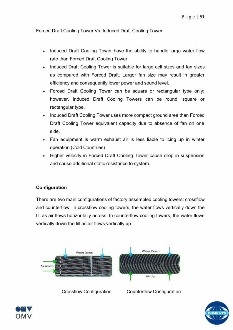
8102019 Gas sweetening Plant
httpslidepdfcomreaderfullgas-sweetening-plant 5562
P a g e | 51
Forced Draft Cooling Tower Vs Induced Draft Cooling Tower
Induced Draft Cooling Tower have the ability to handle large water flow
rate than Forced Draft Cooling Tower
Induced Draft Cooling Tower is suitable for large cell sizes and fan sizes
as compared with Forced Draft Larger fan size may result in greater
efficiency and consequently lower power and sound level
Forced Draft Cooling Tower can be square or rectangular type only
however Induced Draft Cooling Towers can be round square or
rectangular type
Induced Draft Cooling Tower uses more compact ground area than Forced
Draft Cooling Tower equivalent capacity due to absence of fan on one
side
Fan equipment is warm exhaust air is less liable to icing up in winter
operation (Cold Countries)
Higher velocity in Forced Draft Cooling Tower cause drop in suspension
and cause additional static resistance to system
Configuration
There are two main configurations of factory assembled cooling towers crossflow
and counterflow In crossflow cooling towers the water flows vertically down the
fill as air flows horizontally across In counterflow cooling towers the water flows
vertically down the fill as air flows vertically up
Crossflow Configuration Counterflow Configuration
8102019 Gas sweetening Plant
httpslidepdfcomreaderfullgas-sweetening-plant 5662
P a g e | 52
Drift mdash Water droplets that are carried out of the cooling tower with the exhaust
air Drift droplets have the same concentration of impurities as the water entering
the tower The drift rate is typically reduced by employing baffle-like devices
called drift eliminators through which the air must travel after leaving the fill and
spray zones of the tower
Blow-out mdash Water droplets blown out of the cooling tower by wind generally at
the air inlet openings Water may also be lost in the absence of wind through
splashing or misting Devices such as wind screens louvers splash deflectors
and water diverters are used to limit these losses
Blow-down mdash The portion of the circulating water flow that is removed (usually
discharged to a drain) in order to maintain the amount of Total Dissolved Solids
(TDS) and other impurities at an acceptably low level Higher TDS concentration
in solution may result from greater cooling tower efficiency However the higher
the TDS concentration the greater the risk of scale biological growth and
corrosion
Make-up mdash The water that must be added to the circulating water system in
order to compensate for water losses such as evaporation drift loss blow-out
blow-down etc
Approach mdash The approach is the difference in temperature between the cooled-
water temperature and the entering-air wet bulb temperature
Range mdash The range is the temperature difference between the warm water inlet
and cooled water exit
Fill mdash Inside the tower fills are added to increase contact surface as well as
contact time between air and water to provide better heat transfer The efficiency
of the tower depends on the selection and amount of fill
8102019 Gas sweetening Plant
httpslidepdfcomreaderfullgas-sweetening-plant 5762
P a g e | 53
There are two types of fills that may be used
o Film type fill (causes water to spread into a thin film)
o Splash type fill (breaks up falling stream of water and interrupts its
vertical progress)
Important
Scale build up is controlled by adding chemicals to the cooling loop and diluting
the concentration by blow down and make-up Following chemicals are added to
the Cooling to control CorrosionSale and microbial growth
Corrosion Inhibitor To control corrosion in the Cooling system
Dispersant To kept ions in suspension to avoid settle down and buildup
Sodium hypo Chlorite To Control microbial Growth
Acid To control Alkalinity in the system
High Stress Polymer To run the system at higher conductivity It is a
multifunctional polymer for Zinc amp Phosphate stabilization in cooling tower
Fin Fan Cooler
Fin fan heat exchanger is simply a pressure vessel which cools a circulating fluid
within finned tubes by forcing ambient air over the exterior of the tubes A
common example of an air cooler is a carrsquos radiator Fin Fan Coolers are used in
any application where large quantities of heat need to be transferred This
includes chemical and petrochemical industries power stations waste-to-energy
facilities as well as steelworks
Fin Fan Cooler are used for two primary reasons
They increase plant efficiency
They are a green solution as compared to cooling towers and shell and
tube heat exchangers because they do not require an auxiliary water
8102019 Gas sweetening Plant
httpslidepdfcomreaderfullgas-sweetening-plant 5862
P a g e | 54
supply (water lost due to drift and evaporation plus no water treatment
chemicals are required)
Figure General Overview of Fin Fan Cooler
Produced Water
The produced water system receives liquid from the equipment Miano slug
catcher train 1 and 2 inlet separators and is fed to three phase separator where
water oil and gas is separated The gases produced are burnt in incinerator
whereas hydrocarbon liquid is stored to be sold Liquid from compressors
recycle inlet separator recycle feed scrubber high and low pressure slug
catchers is passed to degasser Separated water is injected down the earth
Incinerator
The term incinerate means to burn something until nothing is left but ashes An
incinerator is a unit or facility used to burn trash and other types of waste until it is
reduced to ash An incinerator is constructed of heavy well-insulated materials
so that it does not give off extreme amounts of external heat The high levels of
heat are kept inside the furnace or unit so that the waste is burned quickly and
efficiently If the heat were allowed to escape the waste would not burn as
completely or as rapidly
8102019 Gas sweetening Plant
httpslidepdfcomreaderfullgas-sweetening-plant 5962
P a g e | 55
Control System
The plant is controlled at CCR (Central Control Room) by PLCs (Programmable
Logic Controllers) through fiber optic control line All control parameters are
received at LER (Local Equipment Room) via two optic fiber control lines One
being primary and other secondary operating in redundancy ie if primary fails
control shifts to secondary These control parameters are sent to CCR via single
optic fiber cable
Safety System
Wellheads and Gas Processing Plant have their own Fire amp Gas detection
systems emergency shutdown (ESD) Plant has a fault tolerant controller It is
based on Triple Modular Redundant (TMR) architecture manufactured by
Triconex The TMR system is based on three isolated parallel control systems
integrated into one system The system operates on a two out of three voting
principle which provides high integrity error free uninterrupted operation with no
single point of failure The TMR receives inputs from Process Sensors Manual
Switches Fire amp Gas Detectors Packaged Equipment Control Systems and
Product Exporting Facilities The TMR carries out cause and effect processing on
the data received and where necessary produces output signals Outputs from
the TMR are hard wired directly to ESD shutdown and blow down valve
solenoids motor control instrumentelectrical interfaces to control electrical
drives package equipment logic control systems manifold area as well as
telecoms
The operator in central control room is able to accept alarms and once the fault
has been cleared reset the input All the control systems are centralized to a
single interface All the PLCs (Programmable Logic Controllers) communicate with
the servers and servers communicate with the clients through Ethernet connectivity
Centralization eases the navigation of different systems at a common interface
Emergency Shutdown
The ESD system receives inputs from field mounted instrumentation on the process
8102019 Gas sweetening Plant
httpslidepdfcomreaderfullgas-sweetening-plant 6062
P a g e | 56
and utility equipment and initiates executive actions appropriate to the level of ESD
The system is an Active system which is in standby and will activate when in an
alarm or fault condition The Kadanwari Gas Process Facility ESD system is
comprised of five (5) levels The emergency severity decreases with increasing ESD
level number
ESD 1
This shutdown level is automatically initiated by fire major gas leak or a detected
toxic atmosphere in the process area of the plant or manually from CCR A level 1
shutdown will cause all production to cease close all emergency shutdown
valves stop the process and shutdown of the main power generation The
emergency vent valves to the stack will open and in addition all equipment of zone 1
certified will be isolated This is the highest level of ESD and will cause the following
to occur
All Shutdown Valves (SDVs) on the process facility will close All slowdown Valves (BDVs) on the process facility will open
All Main Gas Driven Generators will be tripped
Emergency Diesel Generator will start
All electrical power to process and utility rotating equipment will be
isolated
Wellhead Choke Valves Close Wing Valves Close Upper Master Valve
(UMV) Close
ESD 2
This shutdown level is activated automatically if a major process or utility failure
occurs or manually from CCR All production to the plant from the wellhead is
stopped All emergency shutdown valves trip to their fail safe position
Venting shall be as specified This level of ESD will cause the following to occur
8102019 Gas sweetening Plant
httpslidepdfcomreaderfullgas-sweetening-plant 6162
P a g e | 57
All Shutdown Valves (SDVs) on the process facility will close
All electrical power to process and utility rotating equipment will be
isolated
Wellhead Choke Valve Close Wing Valves Close and Upper Master Valve(UMV) Close
ESD 3
The level 3 shutdown isolates and stops a single process train only Production
continues via the other train This ESD level is initiated by process conditions or
operator at local panel This level of ESD will cause the following to occur
ESD 3A Train 1 production to cease
ESD 3B Train 2 production to cease
All online wellhead choke valves go to minimum flow ie (1O )
ESD 4
A level 4 shutdown shall cease all production from an entire field either
Kadanwari or Miano upstream of the associated slug catchers ESD 4K for
Kadanwari amp ESD 4M for Miano This ESD level is initiated automatically by slug
catcher abnormal process conditions This level of ESD will cause the following
to occur
All SDVs close isolating the relevant slug catcher and its upstream gas
production facility from the Kadanwari Gas Processing Plant
All Wellhead Choke Valves Close Wing Valves Close and Upper MasterValves (UMV) of the relevant gas production facility Close
A parallel timer is provided to close within 10 second if not closed in given
time SSSV seals the well
ESD 5
A level 5 shutdown represents equipment shutdown for the protection of the
individual equipment without any change in the process This level of ESD is for the
protection of various pieces of equipment and is initiated by its own inputs eg
8102019 Gas sweetening Plant
httpslidepdfcomreaderfullgas-sweetening-plant 6262
8102019 Gas sweetening Plant
httpslidepdfcomreaderfullgas-sweetening-plant 5762
P a g e | 53
There are two types of fills that may be used
o Film type fill (causes water to spread into a thin film)
o Splash type fill (breaks up falling stream of water and interrupts its
vertical progress)
Important
Scale build up is controlled by adding chemicals to the cooling loop and diluting
the concentration by blow down and make-up Following chemicals are added to
the Cooling to control CorrosionSale and microbial growth
Corrosion Inhibitor To control corrosion in the Cooling system
Dispersant To kept ions in suspension to avoid settle down and buildup
Sodium hypo Chlorite To Control microbial Growth
Acid To control Alkalinity in the system
High Stress Polymer To run the system at higher conductivity It is a
multifunctional polymer for Zinc amp Phosphate stabilization in cooling tower
Fin Fan Cooler
Fin fan heat exchanger is simply a pressure vessel which cools a circulating fluid
within finned tubes by forcing ambient air over the exterior of the tubes A
common example of an air cooler is a carrsquos radiator Fin Fan Coolers are used in
any application where large quantities of heat need to be transferred This
includes chemical and petrochemical industries power stations waste-to-energy
facilities as well as steelworks
Fin Fan Cooler are used for two primary reasons
They increase plant efficiency
They are a green solution as compared to cooling towers and shell and
tube heat exchangers because they do not require an auxiliary water
8102019 Gas sweetening Plant
httpslidepdfcomreaderfullgas-sweetening-plant 5862
P a g e | 54
supply (water lost due to drift and evaporation plus no water treatment
chemicals are required)
Figure General Overview of Fin Fan Cooler
Produced Water
The produced water system receives liquid from the equipment Miano slug
catcher train 1 and 2 inlet separators and is fed to three phase separator where
water oil and gas is separated The gases produced are burnt in incinerator
whereas hydrocarbon liquid is stored to be sold Liquid from compressors
recycle inlet separator recycle feed scrubber high and low pressure slug
catchers is passed to degasser Separated water is injected down the earth
Incinerator
The term incinerate means to burn something until nothing is left but ashes An
incinerator is a unit or facility used to burn trash and other types of waste until it is
reduced to ash An incinerator is constructed of heavy well-insulated materials
so that it does not give off extreme amounts of external heat The high levels of
heat are kept inside the furnace or unit so that the waste is burned quickly and
efficiently If the heat were allowed to escape the waste would not burn as
completely or as rapidly
8102019 Gas sweetening Plant
httpslidepdfcomreaderfullgas-sweetening-plant 5962
P a g e | 55
Control System
The plant is controlled at CCR (Central Control Room) by PLCs (Programmable
Logic Controllers) through fiber optic control line All control parameters are
received at LER (Local Equipment Room) via two optic fiber control lines One
being primary and other secondary operating in redundancy ie if primary fails
control shifts to secondary These control parameters are sent to CCR via single
optic fiber cable
Safety System
Wellheads and Gas Processing Plant have their own Fire amp Gas detection
systems emergency shutdown (ESD) Plant has a fault tolerant controller It is
based on Triple Modular Redundant (TMR) architecture manufactured by
Triconex The TMR system is based on three isolated parallel control systems
integrated into one system The system operates on a two out of three voting
principle which provides high integrity error free uninterrupted operation with no
single point of failure The TMR receives inputs from Process Sensors Manual
Switches Fire amp Gas Detectors Packaged Equipment Control Systems and
Product Exporting Facilities The TMR carries out cause and effect processing on
the data received and where necessary produces output signals Outputs from
the TMR are hard wired directly to ESD shutdown and blow down valve
solenoids motor control instrumentelectrical interfaces to control electrical
drives package equipment logic control systems manifold area as well as
telecoms
The operator in central control room is able to accept alarms and once the fault
has been cleared reset the input All the control systems are centralized to a
single interface All the PLCs (Programmable Logic Controllers) communicate with
the servers and servers communicate with the clients through Ethernet connectivity
Centralization eases the navigation of different systems at a common interface
Emergency Shutdown
The ESD system receives inputs from field mounted instrumentation on the process
8102019 Gas sweetening Plant
httpslidepdfcomreaderfullgas-sweetening-plant 6062
P a g e | 56
and utility equipment and initiates executive actions appropriate to the level of ESD
The system is an Active system which is in standby and will activate when in an
alarm or fault condition The Kadanwari Gas Process Facility ESD system is
comprised of five (5) levels The emergency severity decreases with increasing ESD
level number
ESD 1
This shutdown level is automatically initiated by fire major gas leak or a detected
toxic atmosphere in the process area of the plant or manually from CCR A level 1
shutdown will cause all production to cease close all emergency shutdown
valves stop the process and shutdown of the main power generation The
emergency vent valves to the stack will open and in addition all equipment of zone 1
certified will be isolated This is the highest level of ESD and will cause the following
to occur
All Shutdown Valves (SDVs) on the process facility will close All slowdown Valves (BDVs) on the process facility will open
All Main Gas Driven Generators will be tripped
Emergency Diesel Generator will start
All electrical power to process and utility rotating equipment will be
isolated
Wellhead Choke Valves Close Wing Valves Close Upper Master Valve
(UMV) Close
ESD 2
This shutdown level is activated automatically if a major process or utility failure
occurs or manually from CCR All production to the plant from the wellhead is
stopped All emergency shutdown valves trip to their fail safe position
Venting shall be as specified This level of ESD will cause the following to occur
8102019 Gas sweetening Plant
httpslidepdfcomreaderfullgas-sweetening-plant 6162
P a g e | 57
All Shutdown Valves (SDVs) on the process facility will close
All electrical power to process and utility rotating equipment will be
isolated
Wellhead Choke Valve Close Wing Valves Close and Upper Master Valve(UMV) Close
ESD 3
The level 3 shutdown isolates and stops a single process train only Production
continues via the other train This ESD level is initiated by process conditions or
operator at local panel This level of ESD will cause the following to occur
ESD 3A Train 1 production to cease
ESD 3B Train 2 production to cease
All online wellhead choke valves go to minimum flow ie (1O )
ESD 4
A level 4 shutdown shall cease all production from an entire field either
Kadanwari or Miano upstream of the associated slug catchers ESD 4K for
Kadanwari amp ESD 4M for Miano This ESD level is initiated automatically by slug
catcher abnormal process conditions This level of ESD will cause the following
to occur
All SDVs close isolating the relevant slug catcher and its upstream gas
production facility from the Kadanwari Gas Processing Plant
All Wellhead Choke Valves Close Wing Valves Close and Upper MasterValves (UMV) of the relevant gas production facility Close
A parallel timer is provided to close within 10 second if not closed in given
time SSSV seals the well
ESD 5
A level 5 shutdown represents equipment shutdown for the protection of the
individual equipment without any change in the process This level of ESD is for the
protection of various pieces of equipment and is initiated by its own inputs eg
8102019 Gas sweetening Plant
httpslidepdfcomreaderfullgas-sweetening-plant 6262
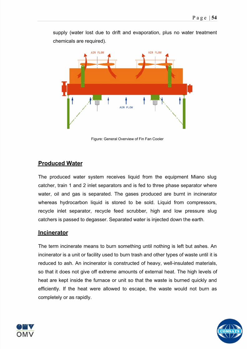
8102019 Gas sweetening Plant
httpslidepdfcomreaderfullgas-sweetening-plant 5862
P a g e | 54
supply (water lost due to drift and evaporation plus no water treatment
chemicals are required)
Figure General Overview of Fin Fan Cooler
Produced Water
The produced water system receives liquid from the equipment Miano slug
catcher train 1 and 2 inlet separators and is fed to three phase separator where
water oil and gas is separated The gases produced are burnt in incinerator
whereas hydrocarbon liquid is stored to be sold Liquid from compressors
recycle inlet separator recycle feed scrubber high and low pressure slug
catchers is passed to degasser Separated water is injected down the earth
Incinerator
The term incinerate means to burn something until nothing is left but ashes An
incinerator is a unit or facility used to burn trash and other types of waste until it is
reduced to ash An incinerator is constructed of heavy well-insulated materials
so that it does not give off extreme amounts of external heat The high levels of
heat are kept inside the furnace or unit so that the waste is burned quickly and
efficiently If the heat were allowed to escape the waste would not burn as
completely or as rapidly
8102019 Gas sweetening Plant
httpslidepdfcomreaderfullgas-sweetening-plant 5962
P a g e | 55
Control System
The plant is controlled at CCR (Central Control Room) by PLCs (Programmable
Logic Controllers) through fiber optic control line All control parameters are
received at LER (Local Equipment Room) via two optic fiber control lines One
being primary and other secondary operating in redundancy ie if primary fails
control shifts to secondary These control parameters are sent to CCR via single
optic fiber cable
Safety System
Wellheads and Gas Processing Plant have their own Fire amp Gas detection
systems emergency shutdown (ESD) Plant has a fault tolerant controller It is
based on Triple Modular Redundant (TMR) architecture manufactured by
Triconex The TMR system is based on three isolated parallel control systems
integrated into one system The system operates on a two out of three voting
principle which provides high integrity error free uninterrupted operation with no
single point of failure The TMR receives inputs from Process Sensors Manual
Switches Fire amp Gas Detectors Packaged Equipment Control Systems and
Product Exporting Facilities The TMR carries out cause and effect processing on
the data received and where necessary produces output signals Outputs from
the TMR are hard wired directly to ESD shutdown and blow down valve
solenoids motor control instrumentelectrical interfaces to control electrical
drives package equipment logic control systems manifold area as well as
telecoms
The operator in central control room is able to accept alarms and once the fault
has been cleared reset the input All the control systems are centralized to a
single interface All the PLCs (Programmable Logic Controllers) communicate with
the servers and servers communicate with the clients through Ethernet connectivity
Centralization eases the navigation of different systems at a common interface
Emergency Shutdown
The ESD system receives inputs from field mounted instrumentation on the process
8102019 Gas sweetening Plant
httpslidepdfcomreaderfullgas-sweetening-plant 6062
P a g e | 56
and utility equipment and initiates executive actions appropriate to the level of ESD
The system is an Active system which is in standby and will activate when in an
alarm or fault condition The Kadanwari Gas Process Facility ESD system is
comprised of five (5) levels The emergency severity decreases with increasing ESD
level number
ESD 1
This shutdown level is automatically initiated by fire major gas leak or a detected
toxic atmosphere in the process area of the plant or manually from CCR A level 1
shutdown will cause all production to cease close all emergency shutdown
valves stop the process and shutdown of the main power generation The
emergency vent valves to the stack will open and in addition all equipment of zone 1
certified will be isolated This is the highest level of ESD and will cause the following
to occur
All Shutdown Valves (SDVs) on the process facility will close All slowdown Valves (BDVs) on the process facility will open
All Main Gas Driven Generators will be tripped
Emergency Diesel Generator will start
All electrical power to process and utility rotating equipment will be
isolated
Wellhead Choke Valves Close Wing Valves Close Upper Master Valve
(UMV) Close
ESD 2
This shutdown level is activated automatically if a major process or utility failure
occurs or manually from CCR All production to the plant from the wellhead is
stopped All emergency shutdown valves trip to their fail safe position
Venting shall be as specified This level of ESD will cause the following to occur
8102019 Gas sweetening Plant
httpslidepdfcomreaderfullgas-sweetening-plant 6162
P a g e | 57
All Shutdown Valves (SDVs) on the process facility will close
All electrical power to process and utility rotating equipment will be
isolated
Wellhead Choke Valve Close Wing Valves Close and Upper Master Valve(UMV) Close
ESD 3
The level 3 shutdown isolates and stops a single process train only Production
continues via the other train This ESD level is initiated by process conditions or
operator at local panel This level of ESD will cause the following to occur
ESD 3A Train 1 production to cease
ESD 3B Train 2 production to cease
All online wellhead choke valves go to minimum flow ie (1O )
ESD 4
A level 4 shutdown shall cease all production from an entire field either
Kadanwari or Miano upstream of the associated slug catchers ESD 4K for
Kadanwari amp ESD 4M for Miano This ESD level is initiated automatically by slug
catcher abnormal process conditions This level of ESD will cause the following
to occur
All SDVs close isolating the relevant slug catcher and its upstream gas
production facility from the Kadanwari Gas Processing Plant
All Wellhead Choke Valves Close Wing Valves Close and Upper MasterValves (UMV) of the relevant gas production facility Close
A parallel timer is provided to close within 10 second if not closed in given
time SSSV seals the well
ESD 5
A level 5 shutdown represents equipment shutdown for the protection of the
individual equipment without any change in the process This level of ESD is for the
protection of various pieces of equipment and is initiated by its own inputs eg
8102019 Gas sweetening Plant
httpslidepdfcomreaderfullgas-sweetening-plant 6262
8102019 Gas sweetening Plant
httpslidepdfcomreaderfullgas-sweetening-plant 6262