Gas Service Manual - Travis Dealer
58
Gas Service Manual PILOT ADJ VENT T O L P I ON OFF HI LO December, 1997 Travis Industries Gas T-Shoot Guide 19203
Transcript of Gas Service Manual - Travis Dealer

Gas Service Manual
PILOT ADJ
VE
NT
TO L PI
ON
OFFHI
LO
AA
AAAA
December, 1997Travis Industries Gas T-Shoot Guide 19203

Table of Contents
Travis Industries Gas T-Shoot Guide 19203
Introduction - 1Troubleshooting Flowchart ................................. 1 - 1Who should use this guide................................. 1 - 2Precautions ................................................... 1 - 2How to use this troubleshooting guide.................. 1 - 2Conventions................................................... 1 - 2Tools required................................................. 1 - 3Spare Components .......................................... 1 - 3Natural Gas ("NG") vs. Propane ("LP") Heaters ...... 1 - 3Lopi Model Determination.................................. 1 - 4Heritage Bay Model Determination ...................... 1 - 4Avalon Model Determination .............................. 1 - 5Avanti Model Determination............................... 1 - 5Fireplace Xtrordinair Model Determination............. 1 - 6Travis Industries Model Determination................. 1 - 6
Troubleshooting Steps - 2Piezo Wire Loose or Damaged.............................. 2 -1Spark Electrode Too Far From Pilot Hood............... 2 - 1Piezo Not Grounded.......................................... 2 - 1Electrode has a Cracked Base............................ 2 - 2Piezo Defective ............................................... 2 - 2Gas Line not Purged ......................................... 2 - 2Propane Tank Empty......................................... 2 - 2Gas Supply Turned Off ...................................... 2 - 3Pilot Tube/Orifice Blocked.................................. 2 - 3Pilot Needs Adjustment ..................................... 2 - 3Thermocouple Defective.................................... 2 - 4
B-Vents Only Spill Switch Circuit Faulty ................... 2 - 5EPU Defective................................................. 2 - 6Thermopile Defective ........................................ 2 - 6Burner Electrical Circuit Faulty ............................ 2 - 7Head Coil Defective .......................................... 2 - 8Incorrect Air Shutter Setting............................... 2 - 8DVÕs Only Incorrect Restrictor Position.................. 2 - 9
Logs Placed Incorrectly..................................... 2 - 9Burner Pan Holes Clogged.................................. 2 - 9Gas Pressure Incorrect (Propane Running Empty) 2 - 10Burner Orifice Obstructed................................ 2 - 11
B-Vents Only Vent not Drafting/ Negative Pressure . 2 - 12DVÕs Only Pilot Blowing Off of Thermocouple......... 2 - 13
Remote Thermostat Faulty ............................... 2 - 14Blower Circuit Faulty ....................................... 2 - 15Blower Defective............................................ 2 - 16Gas Control Knob Doesn't Pop Out .................... 2 - 16Pilot or Main Burner Does Not Shut Off................ 2 - 16
Door & Glass Removal - 3Lopi Spirit, Spirit DV, & Spirit Bay......................... 3 - 1Avalon 700 & 700 DV......................................... 3 - 2Avanti (1995,1996) B-Vent & DV......................... 3 - 3Avanti (1997) B-Vent & DV ................................ 3 - 4FPX 36-DV...................................................... 3 - 5Lopi Heritage Bay (DV and B-Vent)....................... 3 - 6Lopi Heritage Bay Insert .................................... 3 - 7DVS Insert and DVS Fireplace............................. 3 - 8
Burner Pan Components - 4Overview of Burner Disassembly .......................... 4- 1Burner Asembly Removal - BVM, DVS & DVM.......... 4- 2Burner Asembly Removal - DVL Burners................. 4- 3Burner Pan Removal - BVM, DVS & DVM Burners..... 4- 4Burner Pan Removal - DVL Burners....................... 4- 5Burner Orifice Removal....................................... 4- 6Pilot Assembly Removal, - 96 (inflexible pilot tube) ... 4- 7Pilot Assembly Removal, - 97 (flexible pilot tube) ..... 4- 8Pilot Orifice Removal.......................................... 4- 9Thermopile Removal......................................... 4- 10Thermocouple Removal .................................... 4- 10Spark Electrode Removal.................................. 4- 11Piezo Igniter Removal ...................................... 4- 11On/Off Switch................................................. 4- 11Burner Pan Parts............................................. 4- 12
Blower Components - 5Avanti Stove (BV & DV) Blower Removal ................ 5- 1Avalon 700 (BV & DV) Blower Removal................... 5- 2Lopi Spirit (BV & DV) Blower Removal .................... 5- 3Avanti Insert (BV & DV) Blower Removal ................ 5- 4Heritage Bay Insert Blower Removal...................... 5- 4Spirit Bay Insert Blower Removal .......................... 5- 4A20 Blower Assembly - Removal & Disassembly ...... 5- 5DVS Insert Blower Removal ................................. 5- 6DVS Fireplace Blower Removal............................. 5- 7FPX 36-DV Blower Removal ................................. 5- 9Heritage Bay Stove Blower Removal.................... 5- 10Blower Rheostat Removal ................................. 5- 11Blower Snap Disk Removal - Her. Bay & 36-DV ...... 5- 11Blower Snap Disk - All Except Her. Bay & 36-DV.... 5- 12Blower Replacement Parts ................................ 5- 13

Introduction 1 - 1
Travis Industries Gas T-Shoot Guide 19203
Troubleshooting Flowchart
Does the pilot stay lit when the gas control knob is released?
Does the blower work correctly?
Does the pilot ignite with the gas control knob in?
Does the igniter spark?
Gas control knob not held down long enough (30 seconds)
Gas supply turned off (pg. 2-3)
Pilot tube/orifice blocked (pg. 2-3)
Blower starts when heater is hot (15 min. - This is Normal)
Blower circuit may be faulty (pg. 2-15)
Spark electrode too far from pilot hood (pg. 2-1)
Piezo not grounded (pg. 2-1)
Electrode has a cracked base (pg. 2-2)
Piezo defective (pg. 2-2)
Heater unplugged or breaker ÒOFFÓ (Check Outlet & Breaker)
Piezo wire loose or damaged (pg. 2-1)
T O L PI
ON
OFF
T OL PI
ON
OFF
Gas line not purged (pg. 2-2)
Pilot circuit faulty
Spill switch circuit faulty (pg. 2-5)B-Vents Only
Millivolt production inadequatePilot needs adjustment
(pg. 2-3)
Thermocouple Defective (pg. 2-4)
Does the main burner turn on?
On/Off switch, thermostat, or remote control off (turn ÒONÓ)
Gas control knob turned to ÒPILOTÓ (turn to ÒONÓ)
Head Coil Defective (pg. 2-8)
Burner electrical circuit faulty (remote, thermostat, etc.) (pg. 2-7)
Millivolt production inadequateThermopile Defective
(pg. 2-6)
Does the flame look correct?
Flame is blue for first 15 minutes (This is normal)
Flame height may be adjusted too low (Adjust higher)
Burner pan holes may be clogged (pg. 2-9)
Logs placed incorrectly (pg. 2-9)
Gas pressure incorrect (propane running empty) (pg. 2-10)
Orifice may be obstructed (pg. 2-11)
Incorrect Restrictor Position (pg. 2-9)DVÕs Only
Incorrect air shutter setting (pg. 2-8)
Blower is defective (pg. 2-16)
Troubleshooting Flowchart Possible Causes
Yes
Yes
Yes
Yes
Yes
Yes
Propane tank empty (pg. 2-2)
EPU defective (pg. 2-6)
Does the main burner shut off unexpectedly?
AAAA
AAA
Vent not drafting/Negative pressure (pg. 2-12)B-Vents Only
DVÕs Only Pilot lifting off of thermocouple (pg. 2-13)
Spill switch circuit faulty (pg. 2-5)B-Vents Only
Remote Thermostat Faulty (pg. 2-14)
Blower knob is in ÒOFFÓ position (Turn blower knob ÒONÓ)
No
No
No
No
No
No
No
Pilot needs adjustment (pg. 2-3)

1 - 2 Introduction
Travis Industries Gas T-Shoot Guide 19203
Who should use this guide
This guide was developed for service personnel and those selling Travis Industries products.Because of the inherent danger involved with gas appliances, all work must be done by qualifiedpersonnel only. Your local building official will have guidelines for those people considered qualified.The heater must be installed in accordance with the owner's manual and the local building codes, ifany; if not, follow ANSI 223.1. Bring an owner's manual for the heater being serviced in case anyinstallation or maintenance questions arise.
Precautions
Warning Turn off all gas to the unit before working on any component on the gas line
Warning When the gas is on make sure the remote, thermostat, or remote on/off switch does notturn on
Warning Make sure the appliance is unplugged when inspecting the wiring
How to use this troubleshooting guide
This guide uses a flow chart on the inside of the cover to help direct the troubleshooting procedurefrom start to finish. A list of troubleshooting steps is on page 1 for those service personnel familiar withgas appliances. The second portion of this manual is dedicated to removal and replacementinstructions.
Conventions
When this troubleshooting guide refers to a side or direction, use the following diagram to determinedirection.
Right
Left
Fron
t
Back
Abo
veB
elow

Introduction 1 - 3
Travis Industries Gas T-Shoot Guide 19203
Tools required
¥ Nutdrivers, open end & socket wrenches in 1/4", 5/16", 11/32", 3/8", 7/16", 1/2", 7/8", 1"
¥ Gas Leak Detection Device (Gas Sniffer is recommended)
¥ Pressure Sensing Device (Magnehelic or manometer) with 1/2" water column increments(0" to 15" minimum)
¥ Multimeter (with ability to detect millivolts and continuity)
¥ Pipe Wrench
¥ Standard and Phillips-head Screwdrivers
¥ Pipe Sealant
¥ Wire with a male quick-connect attached to each end (called a jumper wire)
¥ Power cord with female quick-connects attached to the hot and common wires (hotwire)
Spare Components
When going on a service call, Travis Industries, Inc. recommends that the following spare componentsbe included to better facilitate a quick diagnosis and repair of the heater. These parts may be used todetermine which portion of the appliance is inoperative and can often make the repair quick andeffective. In addition to the items below, gas line equipment should be included if needed.
¥ Flex Tube or Pipe with Shutoff Valve
¥ Spill Switch Snap disk
¥ Thermopile
¥ Piezo Igniter
¥ Burner Pan w/. Gas Control Valve (NG & LP)
¥ Logs & Ember Strip
¥ Wiring Harness
¥ On/Off Switch
¥ Pilot Assembly (NG & LP)
¥ Replacement Orifices (NG & LP)
¥ Blower Rheostat
¥ Blower Snap disk
¥ 3 Pilot Tubes (with compression fittings)
¥ Blower
Natural Gas ("NG") vs. Propane ("LP") Heaters
Travis Industries' heaters use unique gas control valve pressure-regulators, burners, orifices, pilotorifices, and burner pans for natural gas and propane versions of their heaters. Heaters may beconverted - pay close attention to all details when converting. If you have any questions or concerns,call Travis Industries for details.
1 - 4 Introduction
Travis Industries Gas T-Shoot Guide 19203
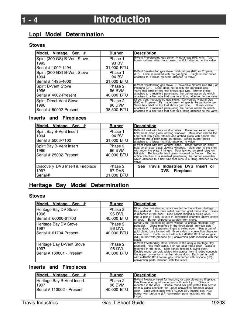
Lopi Model Determination
Stoves
Model, Vintage, Ser. # Burner DescriptionSpirit (300 GS) B-Vent Stove1993Serial # 1002-1494
Phase 193 BV
31,000 BTU
B-Vent Freestanding gas stove. Natural gas (NG) only. Twoburner orifices attach to a brass manifold attached to the valve.
Spirit (300 GS) B-Vent Stove1994Serial # 1495-4600
Phase 194 BV
31,000 BTU
B-Vent freestanding gas stove. Natural gas (NG) or Propane(LP). Label is marked with the gas type. Single burner orificeattaches to a brass manifold attached to valve.
Spirit B-Vent Stove1996Serial # 4602-Present
Phase 296 BVM
40,000 BTU
B-Vent freestanding gas stove. Convertible Natural Gas (NG) orPropane (LP). Label does not specify the particular gas.Valve has label on top that shows gas type. Burner orificeattaches to a manifold penetrating the burner assembly whichattaches to a flex tube that runs to a fitting attached to the valve.
Spirit Direct Vent Stove1996Serial # 50002-Present
Phase 296 DVM
38,500 BTU
Direct Vent freestanding gas stove. Convertible Natural Gas(NG) or Propane (LP). Label does not specify the particular gas.Valve has label on top that shows gas type. Burner orificeattaches to a manifold penetrating the burner assembly whichattaches to a flex tube that runs to a fitting attached to the valve.
Inserts and Fireplaces
Model, Vintage, Ser. # Burner DescriptionSpirit Bay B-Vent Insert1994Serial # 5003-7102
Phase 194 BV
31,000 BTU
B-Vent Insert with bay window sides. Brass frames on sideshold small clear glass viewing windows. Main door utilized theLopi cast iron glass retainer and arched glass with handle thatscrewed into a latch plate on firebox. Single burner orificeattaches to a brass manifold attached to valve.
Spirit Bay B-Vent Insert1996Serial # 25002-Present
Phase 296 BVM
40,000 BTU
B-Vent Insert with bay window sides. Brass frames on sideshold small clear glass viewing windows. Main door is the shellwith mounting plate & hinges. Door latched on small clips onleft side. Rectangular front glass mounted on firebox. Burnerorifice attaches to a manifold penetrating the burner assemblywhich attaches to a flex tube that runs to a fitting attached to thevalve.
Discovery DVS Insert & Fireplace1997Serial #
Phase 297 DVS
31,000 BTU
See Travis Industries DVS Insert orDVS Fireplace
Heritage Bay Model Determination
Stoves
Model, Vintage, Ser. # Burner DescriptionHeritage Bay DV Stove1996Serial # 60000-61703
Phase 296 DVL
40,000 BTU
Direct Vent freestanding stove welded to the unique HeritageBay pedestal. Has three sided, arch top gold frame door. Glassis mounted in the door. Side panels hinged & swing open.Has a pair of Black louvers in convection chamber above centerof door. Burner shipped separately from stove.
Heritage Bay DV Stove1997Serial # 61704-Present
Phase 296 DVL
40,000 BTU
Direct Vent freestanding stove welded to unique Heritage Baypedestal. Glass mounted in the three sided, arch-top goldframe door. Side panels hinged & swing open. Has a pair ofgold plated bars formed with three sides in convection chamberabove door. Each unit is built with a 40,000 BTU natural gas(NG) burner with propane (LP) conversion parts included with thestove.
Heritage Bay B-Vent Stove1997Serial # 160001 - Present
Phase 296 DVL
40,000 BTU
B-Vent freestanding stove welded to the unique Heritage Baypedestal. Has three sided, arch top gold frame door. Glass ismounted in the door. Side panels hinged & swing open.Double round bar gold plated trim across front & sides concealsthe upper convection chamber above door. Each unit is builtwith a 40,000 BTU natural gas (NG) burner with propane (LP)conversion parts included with the stove.
Inserts and Fireplaces
Model, Vintage, Ser. # Burner DescriptionHeritage Bay B-Vent Insert1997Serial # 110002 - Present
Phase 296 BVM
40,000 BTU
B-Vent fireplace insert for masonry or zero clearance fireplace.Has three sided gold frame door with arch top. Glass ismounted in the door. Double round bar gold plated trim acrossfront & sides conceals the upper convection chamber abovedoor. Each unit is built with a 40,000 BTU natural gas (NG)burner with propane (LP) conversion parts included with theinsert.

Introduction 1 - 5
Travis Industries Gas T-Shoot Guide 19203
Avalon Model Determination
Stoves & InsertsModel, Vintage, Ser. # Burner Description700 B-Vent (Gas Stove)19931001-2077
Phase 193 BV
31,000 BTU
B-vent unit, insert or free standing on legs or pedestal. Twoburner orifices attach to a brass manifold attached to the valve.
700 B-Vent (Gas Stove)19942078- 4968
Phase 194 BV
31,000 BTU
B-vent unit, insert or freestanding on legs or pedestal. Singleburner orifice attaches to a brass manifold attached to valve.
700 B-Vent (Gas Stove)19976001 - Present
Phase 296 BVM
40,000 BTU
B-vent unit, insert or freestanding on legs or pedestal. Burner is40,000 BTU (dvm burner) with flex tube leading from right side ofvalve to one orifice. Mixing tube is located under the rearlogshelf. Pilot assembly has thermocouple for 30 second drop-out. There is a raised platform across the front of the burner forthe front log to sit on. A natural gas burner is standard withparts included to convert to LP. Burner orifice attaches to amanifold penetrating the burner assembly which attaches to aflex tube that runs to a fitting attached to the valve. Ser. Nos6001 to 6120 use 96 burners with inflexible pilot tube (burnerremoved to convert to LP). After ser. no. 6121 use 97 burnerswith flexible pilot tube (LP conversion done without removingburner).
700 Direct Vent199650002-Present
Phase 296 DVM
38,500 BTU
Direct vent unit with flex tube attached to right side of the valveleading to one orifice and the mixing tube located under the rearlog support. Has thermocouple for 30 second drop-out. There isa raised "platform" across front of burner for front log to sit on. Anatural gas burner is standard with parts included to convert toLP. Ser. Nos 50002 to 51227 use 96 burners with inflexible pilottube (burner removed to convert to LP). After ser. no. 51227 use97 burners with flexible pilot tube (LP conversion done withoutremoving burner).
Avanti Model Determination
Stoves & InsertsModel, Vintage, Ser. # Burner DescriptionAvanti B-Vent19952503-4050
Phase 195 BV
31,000 BTU
B-vent contemporary style, bay window unit, insert or freestanding. Burner orifice connects directly to gas control valve.Burner is a single thickness sheet metal plate with small uprightflanges near left & right sides at the front to locate the front log.Lift-off gold door is standard.
Avanti B-Vent19964052-Present
Phase 296 BVM
40,000 BTU
B-vent contemporary style, bay window unit, insert or freestanding burner has a raised "platform" for front log to sit on.Has thermo-couple for 30 second dropout. Natural gas burnerstandard, includes parts to convert to LP. Burner orificeattaches to a manifold penetrating the burner assembly whichattaches to a flex tube that runs to a fitting attached to the valve.Ser. Nos 4052 to 5537 use 96 burners with inflexible pilot tube(burner removed to convert to LP). After ser. no. 5537 use 97burners with flexible pilot tube (LP conversion done withoutremoving burner). Lift-off gold door is standard from ser. Nos4052 to 5730. Starting with ser. No. 5731 the swing-open dooris standard.
Avanti Direct Vent19951004-3037
Phase 297 DVS
(modified)31,000 BTU
Direct vent, contemporary style, bay window unit - freestandingonly. Burner is a box assembly with no locator flanges orplatform for the front log to rest on. Has two tall flanges towardback to stop the front log. Has flex tube off right side of valveleading to one orifice and mixing tube located under the rear logsupport. Natural gas burner standard, includes parts to convertto LP. Burner orifice attaches to a manifold penetrating theburner assembly which attaches to a flex tube that runs to afitting attached to the valve. Burner must be removed fromstove to make gas conversion. Has lift-off gold door standard.
Avanti Direct Vent199632002-Present
Phase 296 DVM
38,500 BTU
Direct vent, contemporary style, bay window unit, insert or free-standing. Burner has raised "platform" across front of burner forfront log to sit on. Has thermocouple for 30 second drop-out.Burner orifice attaches to a manifold penetrating the burnerassembly which attaches to a flex tube that runs to a fittingattached to the valve. Natural gas burner is standard with unit.Includes parts to convert to LP. Ser. Nos 32002 to 32986 use96 burners with inflexible pilot tube (burner removed to convertto LP). After ser. no. 32986 use 97 burners with flexible pilottube (LP conversion done without removing burner). Startingwith ser. no. 33189 the swing open door is standard. 40,000BTU dvm burner.
Avanti DVS Insert & Fireplace Phase 297 DVS
31,000 BTU
See Travis Industries DVS Insert orDVS Fireplace

1 - 6 Introduction
Travis Industries Gas T-Shoot Guide 19203
Fireplace Xtrordinair Model Determination
Fireplaces & Inserts
Model, Vintage, Ser. # Burner Description36 DV -A19951004-5967
Phase 296 DVL
40,000 BTU
Arch face only. Ser. Nos. 1004-3037 are natural gas only andhave no intake restrictor. Ser. Nos. 3038-5967 are natural gas orLP and have an exhaust restrictor with pivot adjustor at the topfront of unit behind finish face. Firebox is 30-1/2" wide at front.
36 DV -R199625002-25298
Phase 296 DVL
40,000 BTU
Rectangular face only. All have an exhaust restrictor at the topfront of unit behind face. Firebox is 30-1/2" wide at front.
36 DV- A/R199730000 & continuing
Phase 296 DVL
40,000 BTU
Will accept arch or rectangle faces. Intake restrictor adjustor isa lever located under burn pan at left side. Firebox is 30-1/2"wide at front. Natural gas burner (40,000 BTU) is standardfeature with parts to convert to LP gas included.
FPX 32 DVS Insert & Fireplace Phase 297 DVS
31,000 BTU
See Travis Industries DVS Insert orDVS Fireplace
Travis Industries Model Determination
Fireplaces & Inserts
Model, Vintage, Ser. # Burner DescriptionDVS Insert199680000 & continuing
Phase 297 DVS
31,000 BTU
Must be installed into existing zero clearance or masonryfireplace. Will accept arch or rectangle faces. Firebox is 24"wide at front. No intake restrictor. 31,000 BTU natural gasburner is standard with parts to convert to LP gas included.
DVS Fireplace1997100001 & continuing.
Phase 297 DVS
31,000 BTU
This unit is a zero clearance fireplace. Intake restrictor is athree position lever under burner at right. Will accept either archor rectangle face. Firebox is 24" wide at front. 31,000 BTUnatural gas burner is standard with parts to convert to LP gasincluded.

Troubleshooting Steps 2 - 1
Travis Industries Gas T-Shoot Guide 19203
Piezo Wire Loose or Damaged
Make sure the orange wire is attached to the piezo igniter and is not damaged (make sure it has notcontacted the bottom of the burner pan).
Make sure the orange wire is attached to the piezo igniter and is not damaged.
Piezo Igniter
Piezo Wire (orange)
Remedy
Connect the piezo wire, making sure the connection is tight (crimp slightly if necessary). If the wire isdamaged, replace the pilot assembly which includes a new piezo igniter wire.
Spark Electrode Too Far From Pilot Hood
The spark electrode should be no more than 1/8Ó from the pilot hood. You should see the spark travelfrom the electrode to the pilot hood.
Pilot Hood
No more than 1/8"Spark Electrode
Remedy
Bend the spark electrode so that it is within 1/8" of the pilot hood. The diagonal offset in the electrodeallows it to be bent closer to the pilot hood if necessary (use needle-nose pliers).
Piezo Not Grounded
The grounding tab must make contact with the mounting plate.
Grounding Tab
Piezo Igniter
Remedy
If you suspect the piezo igniter is not grounded, remove it and check to make sure the tab is exposedand undamaged. Bend the piezo grounding tab out or replace the piezo igniter.

2 - 2 Troubleshooting Steps
Travis Industries Gas T-Shoot Guide 19203
Electrode has a Cracked Base
If the spark electrode has a cracked ceramic base the spark will occur at the base Ð not near the pilothood. Look down at the pilot assembly from the top to inspect. Cracking or an uneven spacebetween the insulator and the electrode indicates possible grounding near the base. If uncertain,remove the pilot assembly and inspect.
Pilot Hood
Electrode
Ceramic Base
Remedy
Replace the pilot assembly.
Piezo Defective
Defective piezo igniters will not create the electrical charge necessary. You may notice that the redbutton does not create a "snap" when it is depressed or that the button has no spring resistance. Theonly way to check this component is to replace it and see if it creates a spark.
Remedy
Replace the piezo igniter.
Gas Line not Purged
All air in the gas line must be purged prior to operation.
Remedy
Remove the glass (or open the door) and depress the gas control knob (on pilot) while repeatedlypressing the igniter until the pilot lights.
Propane Tank Empty
Make sure propane is still supplied. To verify, check the gas inlet pressure (see "Gas PressureInadequate" on page 2-10).
Remedy
Re-fill propane tank.
Gas Supply Turned Off
Make sure all gas shut-offs are open. To verify, check the gas inlet pressure (see "Gas PressureInadequate" on page 2-10).
Remedy
Turn gas shut-off valves to "ON".

Troubleshooting Steps 2 - 3
Travis Industries Gas T-Shoot Guide 19203
Pilot Tube/Orifice Blocked
If no gas is present at the pilot hood, check for blockage in the tube inside the pilot hood. Check forgas flow by carefully listening for air flow from the pilot hood. If blockage is not found, remove the pilotorifice and check for debris.
The pilot tube is often overlooked as a source of gas leakage. Check both pilot tube connectionsafter making any alteration to the pilot tube or pilot assembly (use a gas leak detector)
Pilot Hood
Pilot orifice(inside pilot assembly)
Check for blockage here.
Remedy
Remove any blockage from pilot orifice or pilot tube by forcing air through it. Replace if necessary.
Pilot Needs Adjustment
The pilot flame should impinge the top 3/8Ó of the thermopile and thermocouple.
The pilot flame should impinge the top 3/8Ó (10 mm) of the thermopile. If it does not, you may need to turn the pilot up.
To adjust the pilot flame, remove the cover screw (and gasket) and turn the needle valve. Clockwise lowers the flame while counter-clockwise raises it.
PILOT ADJ
TO L PI
ON
OFF
Standard Screwdriver
Micro (1/16Ó) Standard Screwdriver
AA
The cover screw and gasket must be replaced to prevent gas from leaking
Cover Screw
Cover Screw Gasket
Needle Valve
3/8Ó (10 mm)
Thermopile
Pilot Hood
Thermocouple
NOTE: The thermopile millivolt production can be monitored while adjusting the pilot. Placemultimeter problems on the middle and lower posts of the gas control valve (see page 2-6). Millivolt production is factory set at approximately 400. If you can not adjust the pilot toachieve 200 millivolts, your thermopile may require replacement. See the section"Thermopile Defective" on page 2-6 for more details.
Remedy
To adjust the pilot flame, remove the cover screw (and gasket) and turn the needle valve. Clockwiselowers the flame while counter-clockwise raises it.
The cover screw and gasket must be replaced to prevent gas from leaking.

2 - 4 Troubleshooting Steps
Travis Industries Gas T-Shoot Guide 19203
Thermocouple Defective
To check the millivolt production from the thermocouple, remove the thermocouple connector andconnect the multimeter to the center tab and copper tube. Start the pilot and hold down the gascontrol knob. The minimum acceptable reading is 15 millivolts.
PILOT ADJ
VE
NT
TO L PI
ON
OFF
HI
LO
To check millivolt production from the thermocouple, remove the thermocouple connector and connect the multimeter to the center tab and copper tube (min. 15 millivolts).
Thermocouple Connector
3/8"
Wre
nch
B-Vents Only
Copper Tube
NOTE: Make sure the pilot flame contacts the thermocouple 3/8" (for 30 seconds) while testingmillivolt production. If it does not, see "Pilot Flame Needs Adjustment".
Remedy
Replace the pilot assembly (includes thermocouple).

Troubleshooting Steps 2 - 5
Travis Industries Gas T-Shoot Guide 19203
B-Vents Only Spill Switch Circuit Faulty
The spill switch circuit disables theheater if spillage is detected fromthe draft hood. If a connectionbetween the components is loose,corroded, or damaged, the circuitwill be disabled and the pilot will notstay lit when the gas control knob isreleased. To check the spill switchcircuit, follow the directions below.
1 Start the pilot and hold downthe gas control knob. Groundone of the multimeter probes tothe copper tube on thethermocouple connector.
2 Use a multimeter to measurethe millivolt reading on the spillswitch interrupt terminalnearest the thermocoupleconnector. If no millivolts aredetected, and thethermocouple is producingmillivolts (see "ThermocoupleDefective" pg. 2-4), thethermocouple connector is notattached correctly.
PILOT ADJ
VE
NT
TO L PI
ON
OFF
HI
LO
AAAAA
Thermocouple Connector
Spill Switch Wires (Red)Orientation does not matterwhen re-connecting
1
23
Spill Switch Interrupt
3 Replace the spill switch wire nearest the thermocouple connector and measure the millivoltreading on the other terminal of the spill switch interrupt. If no millivolts are detected, andmillivolts were detected in step 2 above, the spill switch wires or spill switch snap disk is faulty(see steps 4 & 5 below). If millivolts are detected (minimum of 15 millivolts), yet the pilot does notstay lit, the spill switch interrupt is not attached to the gas control valve correctly.
4 Carefully Inspect the spill switchwires for damage or looseconnections. If the wireinsulation is melted and thewire contacts a metal surface,the thermocouple circuit willground out to the chassis ofthe heater and disable theheater. Replace damaged wire.
5 Remove the rear panel of theheater (if applicable) to accessthe spill switch. Remove thetwo red wires leading to the spillswitch and check for continuityon the spill switch. Replace ifno continuity is detected.
Remedy
Replace or repair the appropriatecomponent based upon the abovetroubleshooting steps.
Spill Switch
Draft Hood
AAAA
AA
Spill Switch Wires (Red)Orientation does not matter when re-connecting.

2 - 6 Troubleshooting Steps
Travis Industries Gas T-Shoot Guide 19203
EPU Defective
If the thermocouple production is adequate (see "Thermocouple Defective"), yet the pilot does notstay lit when the knob is released, the EPU inside the gas control valve is malfunctioning.
Remedy
Replace the gas control valve.
Thermopile Defective
To check millivolt production form the thermopile, connect the multimeter to the center and lowerposts on the gas control valve. Millivolt production is factory set at approximately 400 millivolts(with the burner off).
Gas Control Valve
PILOT ADJ
VE
NT
TOL PI
ON
OFF
HI
LO
AAAAAAAA
NOTE: leave the knob on "PILOT"
Make sure the pilot flame contacts the thermopile 3/8" (for 30 seconds) while testing millivoltproduction. If it does not, see "Pilot Flame Needs Adjustment". If you can not adjust the pilot toachieve 200 millivolts, your thermopile may require replacement.
NOTE: If the main burner is turned on, the millivolt production will appear to drop because thehead coil (the valve that operates the main burner) will draw electricity.
NOTE: If the heater operates for 1 to 5 minutes, then shuts off, it may be a defective thermopile.Millivolt production is based upon the difference in temperature between the top andbottom of the thermopile. A defective thermopile may create sufficient millivolts to keepthe main burner operating for the first minutes of operation. But once the stove warms,the temperature differential lessens and millivolt production goes down.
NOTE: When using a thermostat or remote control, the millivolt production may need to beincreased in certain cases (see page 2-3 for pilot adjustment). The thermostat or remotewire creates electrical resistance in the main burner circuit, making larger millivoltproduction necessary to offset the resistance.
Remedy
Replace the thermopile (or pilot assembly).

Troubleshooting Steps 2 - 7
Travis Industries Gas T-Shoot Guide 19203
Burner Electrical Circuit Faulty
The burner electrical circuit controls the main burner. If any item, including the wiring, is faulty, theburner will not turn on. This also applies to any remote components (remote control, thermostat, wallswitch) used to operate the burner. Follow the steps below to diagnose the burner electrical circuit.
Gas Control Valve
PILOT ADJV
EN
T
HI
LOAAAAAAAA
Red
Brown
AAAAAAAA
OF
F
ON
AAAA
The switch may be connected to a thermostat or remote control reciever.
NOTE:
3
1
2
2
Jumper Wire
1 Make sure the pilot is burning and the gas control knob is turned to "ON". Remove thebrown and red wire connected to the top and bottom posts of the gas control valve.Connect a jumper wire between the top and bottom posts. If the heaters turns on, theburner electrical circuit is faulty - go to step 2 below. If the heater does not turn on (andthe thermocouple production is adequate) the head coil inside the gas control valve isdefective (replace the gas control valve).
2 Turn off the appliance and carefully inspect the burner electrical circuit wires for damage orloose connections.
HINT: Keep in mind that millivolt circuits are very weak. Unlike 110 Volt circuits, a slightly looseconnection can interrupt the circuit and disable the burner. The most frequent cause forfaulty on/off circuits are connections that are loose or dirty. Remove, clean, and re-crimpall connections before replacing components or wiring.
NOTE: If the wire insulation is melted and the wire contacts a metal surface, the on/off circuit willground out to the chassis of the heater and disable the main burner. Any wiring that isexposed or severed should be replaced or properly insulated.
3 If no wiring is found damaged, turn on the pilot and trace the burner electrical circuit.Keep one probe of the multimeter on the center post of the gas control valve whilesystematically following the circuit. Start with the red wire leading to the on/off switch.You should detect millivolts where it connects to the on/off switch. If it does not, replaceor re-connect the wire to fix the circuit. Repeat this process for the on/off switch, jumperwire (or remote/thermostat), and brown wire until the bad connection is found.
Remedy
Replace or fix the faulty component.

2 - 8 Troubleshooting Steps
Travis Industries Gas T-Shoot Guide 19203
Head Coil Defective
If the thermopile production is adequate (see "Thermopile Defective") and the burner does not turnon when jumped(see step #1 under "Burner Electrical Circuit is Faulty"), yet the burner does not turnon, the Head Coil inside the gas control valve is malfunctioning.
Remedy
Replace the gas control valve.
Incorrect Air Shutter Setting
The air shutter regulates the amount of air allowed into the mixing tube prior to ignition on the burner.It is factory-adjusted for use near sea level. But due to venting configuration, gas quality, and altitude,the air shutter should be adjusted for each installation. The flames should be blue at the base andorange/yellow at the top with no sooting. When adjusted correctly, the flames will be efficient andattractive.
1 Start the heater, and let it burn for 15 minutes.
2 Inspect the flames.
Gas Control Valve
PILOT ADJ
VE
NT
HI
LO
CorrectFlames should be blue at the base, yellow-orange on the top.
If the flames are too tall or sooty on the ends, push up on the lever.
If the flames are all blue and short, pull down the lever.
Not Enough Air Too Much Air
Locate the air shutter adjustment lever behind the gas control valve. Move it up or down until the flame is correct. Pushing up gives the flame more air (making it bluer). Pulling it down cuts air down, making it more orange.
NOTE: If the air control is all the way up, yet the flames remain sooty, shut off gas to the fireplace and contact a qualified gas service technician. NOTE: The logs must be installed correctly to
monitor the flame while adjusting the air shutter.
TO
L
PI
ON
OF
F
NOTE: The logs must be installed correctly to monitor the flame while adjusting the air shutter.Locate the air shutter adjustment lever behind the gas control valve.
NOTE: If the air control is all the way up, yet the flames remain sooty, make sure to check therestrictor position (on DVÕs only), gas inlet pressure, and log position.
Remedy
Move the air shutter lever up or down until the flame is correct. Pushing up gives the flame more air(making it bluer). Pulling it down cuts air down, making it more orange.

Troubleshooting Steps 2 - 9
Travis Industries Gas T-Shoot Guide 19203
DVÕs Only Incorrect Restrictor Position
Direct vent appliances require a restrictor to regulate exhaust velocity. With the restrictor set too low,the flames will flutter and the flames will be short. Set too high, the flames will be lazy and it may bedifficult to set the air shutter position to a clean, yet attractive, flame.
Remedy
Use the chart in the owner's manual to determine the restrictor position.
The restrictor position indicated in the owner's manual is based upon lab tests. The optimum settingmay be slightly different.
Logs Placed Incorrectly
The ceramic fiber logs must be placed correctly on the burner pan for the heater to burn correctly. Toomuch flame impingement on the logs, sooting, or no "glowing" are symptoms of incorrectly placedlogs (or an incorrectly adjusted air shutter). This may lead to excessive sooting, increased emissions,shortened flames, and decreased efficiency.
Remedy
Place the logs correctly (see the ownerÕs manual).
Burner Pan Holes Clogged
If the flames on the heater do not completely light across the width of the burner, there may be somedebris clogging the burner pan holes (check for any pieces of log that may have chipped off, lint, etc.).There might also be occasional "lifting" of flames in this case.
Remedy
Remove the logs from the burner and clean all the burner pan holes.

2 - 10 Troubleshooting Steps
Travis Industries Gas T-Shoot Guide 19203
Gas Pressure Inadequate (Propane Running Empty)
Improper input pressure may lead to abnormal flame height or inability to achieve a clean flame. Followthe procedure below to check input pressure.
! Whenever working with gas, make sure to follow the proper precautions.This procedure opens the gas line - use extreme care.
! Do not press the piezo igniter until you are certain there is no gas leak orgas buildup inside the firebox.
Note: Gas appliances on the same gas line may affect input pressure. Check input pressurewhile the other appliances are on to see if pressure is correct.
Note: Make sure to check the propane level if using propane.
1 Turn the gas control knob to off.
2 Follow the directions below to access a gas port and attach a manometer (or otherpressure sensor).
Manometer or other Pressure Sensing Device
LP
11" W.C.
NG
5.5" W.C.
Min. Input Pressure
PILOT ADJ
TO L PION
OFF
Standard Screwdriver
Micro (1/16Ó) Standard Screwdriver
A
Cover Screw
Cover Screw Gasket
Needle Valve
Older Models
a Remove the cover screw (and gasket).b Unscrew the needle valve several turns.c Place a tube over the needle valve port.
Newer Models (with Gas Inlet Pressure-Test Port)
a Unscrew the gas inlet pressure-test port needle valve several turns.b Place a tube over the needle valve port.
TOL PI
ON
OFF
PILOT ADJ
OU
TIN
INGas Inlet Pressure-Test Port
Micro (1/16Ó to 1/8") Standard Screwdriver
A
3 Start the pilot, making sure to keep the test port covered the entire time.
4 Monitor the inlet pressure with the main burner on.
Warning: Gas will come out of the test port. Make sure to turn the gas control knob to off andextinguish all flames prior to removing the tube.
Note: You may follow the same procedure to purge the gas line, monitoring for gas at theneedle valve location.
Remedy
Correct the gas inlet pressure. This may entail adjusting the regulator or increasing the pipe diameter.

Troubleshooting Steps 2 - 11
Travis Industries Gas T-Shoot Guide 19203
Burner Orifice Obstructed
The orifice(s) work in conjunction with the gas control valve to provide the correct amount of gas to theburner pan. Any obstruction (debris from gas line installation) caught in an orifice will lead to improperperformance. Follow the instructions below to check for obstructions.
While the orifice(s) are removed, check the inside of the mixing tubes for obstructions.
Always use thread sealant when replacing the orifice(s).
Check for clogging by removing the orifice and looking inside.
Orifice (removed from back side ofmanifold)
1 If the flame height is less than 6" tall in the rear, or 2" in front, the orifice(s) may need to bechecked for obstructions. First check the input pressure to see if that is correct, thenadjust the air shutter. If the flames remain too short, remove the orifice(s) and check fordebris inside.
2 While the orifices are removed, use a flashlight to inspect the inside of the mixing tubesfor any type of obstructions that may interfere with gas/air flow (check for lint, cobwebs,dirt, etc.). If any debris is lodged in the orifice remove the debris by forcing air through it.Do not poke or ream out the orifice to clean it.
Remedy
The orifices or inside of mixing tubes will need to be cleaned (force air through it) or replaced.

2 - 12 Troubleshooting Steps
Travis Industries Gas T-Shoot Guide 19203
B-Vents Only Vent not Drafting/ Negative Pressure Situation
If a b-vent appliance shuts down within 5 minutes of starting, chances are it encountered a cold-airblock or negative pressure. In most cases you can re-start the appliance and it will draft properly.However, if persistent shut-downs occur, you may wish to check for negative pressure.
Negative Pressure
Negative pressure describes a situation in which less pressure isinside the home (near the heater) than outside. This allows air torush down the vent. Because B-Vent heaters utilize natural draftto pull combustion products up the vent, negative pressure cancause combustion products to spill into the room. The spill switchthen detects the heat and shuts the heater off. The pilot will thenneed to be re-started. The following are possible causes ofnegative pressure:
¥ Exhaust Fans in Air-Tight Homes
Kitchen Jenn-Air type fans, dryers, or bathroom fans can pull airout of the home, causing air to come down the vent.
Remedy
Turn all exhaust fans off while starting the heater. If this is notfeasible, the heater may need to be re-started a couple of timesto generate draft. In severe cases, supply outside air to theappliance to overcome negative pressure (install an outside air kitor crack the window).
¥ Down Drafts
Installations in a high-wind area may lead to air pushing down thegas vent. Homes located next to a lake or on the leeward side oftall trees or a hill are most susceptible. This type of problem maybe sporadic.
Remedy
Increase the vent height above the downward flow of air or installa draft-inducing hood or draft inducer.
¥ Thermal Negative Pressure
Thermal negative pressure describe a situation in which thehome circulates warm air up and out of the home. Cold air thenreplaces it by coming down the vent. This type of negativepressure can be pervasive. Homes with un-sealed, un-insulatedceilings are especially susceptible. A heater located in a coldbasement compounded by air exiting through the upper portionsof the home is another scenario. In homes with two fireplaces ondifferent levels, you might notice the downstairs fireplace tendsto draw air in while the upstairs fireplace will pull the warmer air outof the home.
Remedy
This type of negative pressure is extremely difficult to diagnoseand remedy. Make sure the attic or ceiling area is sealed andinsulated. In severe cases the heater may need an outside air kitor draft inducer.
AAAAAAAAAAAAAAAAAA
Kitchen or bathroom fan
Draft Hood
AAAAAAAAAAAAAAAAAAAAAAAAAAAAAAAAAAAAAAAA
AAAAAAAAAAAAAAAAAAAAAAAA
AAAAAAAAA
AAAAAAAAAAAAAAAAAAAA
AAAAAAAAAAAAAAAA

Troubleshooting Steps 2 - 13
Travis Industries Gas T-Shoot Guide 19203
DVÕs Only Pilot Blowing Off of Thermocouple
If the pilot goes out sporadically, inspect the pilot flame near the thermocouple. Watch the flame tosee if it blows off of the thermocouple. Check this after shutting off the main burner.
Check to see if the pilot flame is being blown off of the thermocouple.
Thermocouple
Remedy
Make sure the vent restrictor is in the correct position (see the ownerÕs manual for details).
Make sure vertical terminations utilize the high-wind cap (part # 991)
36-DVÕs and Heritage Bays should have a pilot deflector - if they do not, contact Travis Industries fordetails.
If the Heritage Bay or 36-DV does not have this deflector, contact Travis Industries.
2 - 14 Troubleshooting Steps
Travis Industries Gas T-Shoot Guide 19203
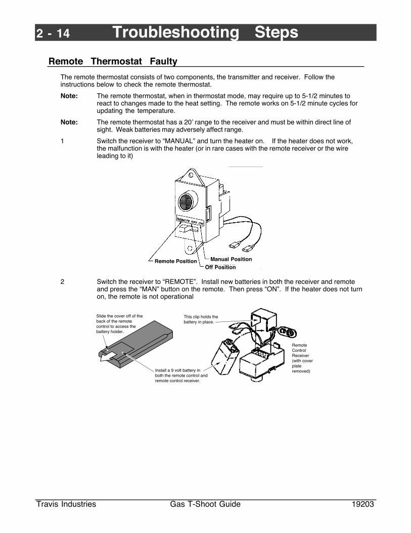
Remote Thermostat Faulty
The remote thermostat consists of two components, the transmitter and receiver. Follow theinstructions below to check the remote thermostat.
Note: The remote thermostat, when in thermostat mode, may require up to 5-1/2 minutes toreact to changes made to the heat setting. The remote works on 5-1/2 minute cycles forupdating the temperature.
Note: The remote thermostat has a 20Õ range to the receiver and must be within direct line ofsight. Weak batteries may adversely affect range.
1 Switch the receiver to ÒMANUALÓ and turn the heater on. If the heater does not work,the malfunction is with the heater (or in rare cases with the remote receiver or the wireleading to it)
Remote PositionOff Position
Manual Position
2 Switch the receiver to ÒREMOTEÓ. Install new batteries in both the receiver and remoteand press the ÒMANÓ button on the remote. Then press ÒONÓ. If the heater does not turnon, the remote is not operational
Install a 9 volt battery in both the remote control and remote control receiver.
Slide the cover off of the back of the remote control to access the battery holder.
This clip holds the battery in place.
Remote Control Receiver (with cover plate removed)

Troubleshooting Steps 2 - 15
Travis Industries Gas T-Shoot Guide 19203
Blower Circuit Faulty
The blower circuit controls the electricity flowing to the blower. It consists of a power cord, wiringharness, snap disk, and rheostat. This allows the blower to be variable speed and shut downautomatically when the heater cools. The two symptoms below detail the troubleshooting steps forthe blower circuit (the blower circuit is 115V A.C., not a D.C. millivolt system).
Disconnect the power supply before servicing electrical components.
Blower is stuck on High
This indicates a defective rheostat. Replace the rheostat (see the directions below).
Blower does not turn ÒONÓ
The blower will not start until the heater is up to temperature - approximately 15 minutes. This time islonger if the flame is turned to low.
1 Check the outlet to make sure it is supplying power.
2 With the power cord removed, check the wiring using the diagram below as a guide. Usea multimeter to check continuity between the wires. Check for loose connections orburned wire insulation. Replace any damaged component.
Molex Plug
Grounding wire (screwed to heater)
Wires from the power cord
Blower Rheostat
White
Black
Black
Green
Blower
Black
Black
White
WhiteBlower Snap Disk
3 With the power off, access the blower snap disk (it is found on the back side of the fireboxon stoves and inserts and underneath the burner pan on fireplaces. Disconnect the twowires leading from it and ÒjumpÓ them together with a wire that has two male quick-connects attached. This will bypass the snap disk. If the blower then turns on when thepower is restored, the snap disk is defective and should be replaced.
Blower Snap Disk
Remove the wires from the snap disk
Attach a jumper wire to the two wires leading to the blower snap disk.
Black
White

2 - 16 Troubleshooting Steps
Travis Industries Gas T-Shoot Guide 19203
Blower Defective
A defective blower may be loud or not circulate air. This component is not user serviceable and mustbe replaced if defective. The blower is checked by attaching it to a hotwire (a power cord with a femalequick connect on the hot and common wire). Follow the directions for accessing the blower in thesection "Removing the blower" (NOTE: do not remove the blower, simply follow the instructions untilthe blower wires can be accessed). If the blower does not turn on or is especially loud, it is defective.
Remedy
Replace the blower.
Gas Control Knob Doesn't Pop Out when Released
If the gas control knob does not pop out when released after starting the pilot, the EPU inside the gascontrol valve is not working correctly.
PILOT ADJ
VE
NT
TOL PI
ON
OFF
HI
LO
If the gas control knob does not pop out
w hen released, the gas control valve
M UST BE REPLA CED IM M EDIA TELY.
Warning: This is a potentially dangerous situation.
Remedy
Turn the gas control knob to "OFF", shut off gas to the heater, and do not operate the heater until thegas control valve is replaced.
Pilot or Main Burner Does Not Shut Off
If the pilot or main burner does not shut off correctly, there may be blockage inside the gas controlvalve. Make sure the thermostat or remote control is operating correctly.
Remedy
Replace the gas control valve.

Door & Glass Removal 3 - 1
Travis Industries Gas T-Shoot Guide 19203
Lopi Spirit, Spirit DV, & Spirit Bay
Remove the door by lifting up on it and swinging it to the left. Then lift it up and off of the hinges.Remove the glass by following the directions below.
Cross Section of Glass Attachment AAA
AAA
AAAAAA
AAA
Glass
Glass Gasket (5/8" self-adhesive channel gasket)
Glass Clip
Glass Clip Attachment Studs
Face of Heater
Glass Clip Nuts
a5/
16"
Nut
driv
er
AAAAAAAAAAAAAAAAAAAAAAAAAAAAAAAAAAAAAAAA
bLoosen the nuts on the bottom and left side glass clip. Then slide the glass to the right, pivot the glass forward, and remove it from the heater.
AAAAAAAAAAAAAAAAAAAAAAAAAAAAAAAAAAAA
Follow the directions above in reverse order. Make sure the gasket forms an air-tight seal around the perimeter of the glass.
To remove the glass:
To replace the glass:
Loosen the nuts on the top and right side glass clips. Then slide the glass clips off.
AAAAAAAAAAAAAAAAAAAAAAAAAAAAAAAAAAAA
NOTE: Some models do not have key-hole slots in the glass clips. Simply remove the nuts toremove the glass clips.

3 - 2 Door & Glass Removal
Travis Industries Gas T-Shoot Guide 25903
Avalon 700 & 700 DV
Remove the door following the directions below.
Unscrew and remove the door handle.
NOTE: When re-installing, make sure the handle points away from the glass when finished.
Swing the door until it is open 90¡ Lift the door up and away from the heater.
The door components are shown below.
3/8" flat gasketing behind the retaining clips (prevents the glass from cracking when being secured.
Use a 5/16" nutdriver for the retaining clip screws.
Door Gasket -7/8" rope gasketing is held in place with gasket cement.
Cross Section
Door Frame
Glass
Retaining Clip
Glass Gasket -3/8" dia. white rope gasket
Make sure there is a small space around the edge of the glass
AAAAAA
AAAAAAAAAAA
The glass is held in place with the retainer clips and a 5" piece of 3/8" flat white gasketing.

Door & Glass Removal 3 - 3
Travis Industries Gas T-Shoot Guide 19203
Avanti (1995,1996) B-Vent (ser. # 2503 - 5730) & DV (ser. # 1004 - 33188)
Remove the door followingthe directions to the right.
The door hangs on a pair of hooks on both sides. Lift the door up and off the hooks to remove. To replace, align the brackets on the door over the hooks and slide downwards until the door locks in place.
Hooks on Side of Heater
Door
Bracket (on back side of door)
Remove the glass followingthe directions to the right.
AAAAAAAAAA
AAAAAA
AAAAA
Side GlassCenter
Glass AAAAAA
AAAAAA
A
AAAAAA
Remove the top glass clip.
AAA
5/16
" N
utdr
iver
AAAAAAAAAAAAAAA
a
b
AAAAAAAAAAAAAAAAAAAAAAAA
Place one hand on the glass.Loosen the four nuts on the bottom glass clip until the glass can be tilted forward and removed.
Loosen the three glass clips holding the side glass in place. Slide the side glass to the rear Do these steps for both sides.
Remove the glass trim on both sides.
c
DV's Only
Replace the glass followingthe directions to the right.
AAAAA
AAAAA
AAAA
AA
AAAAAAAA
Glass
Glass Gasket (5/8" self-adhesive channel gasket)
Glass Clip
Glass Clip Attachment Studs
Face of Heater
Cross Section of Glass Attachment
5/16
" N
utdr
iver
Right Side Glass
Center Glass
Lower Glass Clips
Upper Glass Clips
Side Glass Clip
Glass Clip Nuts
Top View
AAAAAAAAAAA
Glass Trim (make sure both pieces of glass butt up against the trim)
Right Side Glass
CenterGlass
AA
AAAAA
AA
Right Side Glass
AAAAAAA
AAAAAAA
CenterGlass
AA
AAAAA
AA
Left Side Glass
The side glass has gasket attached to the top, bottom and outward sides. The center glass has gasket on the top and bottom.
Glass Gasket
DV's Only
3 - 4 Door & Glass Removal
Travis Industries Gas T-Shoot Guide 19203
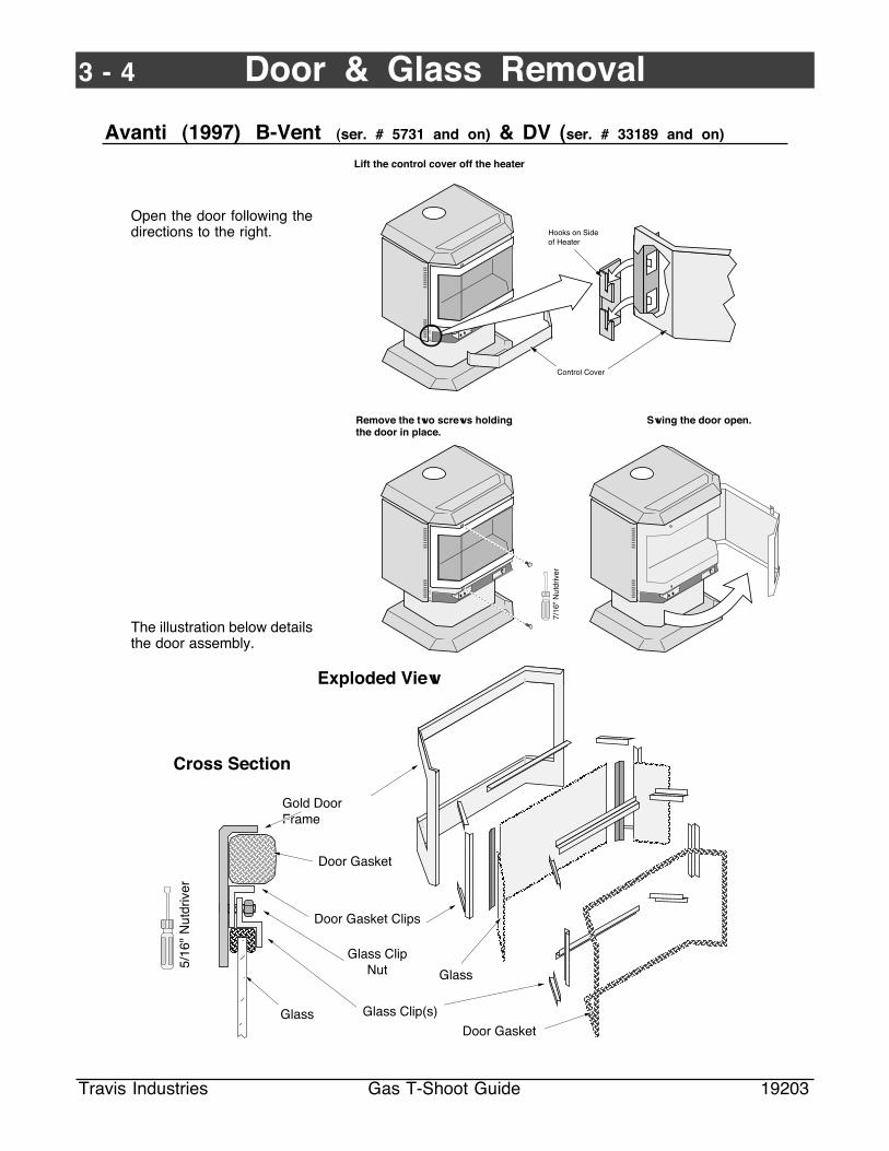
Avanti (1997) B-Vent (ser. # 5731 and on) & DV (ser. # 33189 and on)
Open the door following thedirections to the right.
The illustration below detailsthe door assembly.
Lift the control cover off the heater
Hooks on Side of Heater
Control Cover
Remove the two screws holding the door in place.
Swing the door open.
7/16
" N
utdr
iver
AAAAAA
AAAAAAAAAAAAAAAA
AAAAAA
AAAAAAAA
AAAA
AAAAAAAA
AAAAAAAAA
AAAAAAA
AAAAAAAAAAAA
AAAAAAAAAAAAAAAAAAAAAAAAAAAAAAAAAAAAAA
AAAAAAAAAAAAAAAAAAAAAAAAAAAAAAAAAAAAAAAA
AAAA
AAAAAAAAAA
AAAAAAAA
AAAAAA
AAAAAAAAAAA
AAAA
AAAA
AAAA
AAAAAAAA
AAAAAAAA
AAAAAAAA
AAAAAAAAAAAAAAAAA
AAAAAAAAAAAAA
AAAAAA
AAAAAA
AAA
AAA
AAAAAA
AAAAAA AAAA
AAAAAAAAAAAAAAAAAAAAAAAAAAAAAAAA
AAAAAA
AAAAAAAAAAAAAAAAAAAAAAAAAAAAAAAAAAAAAAAA
AAAAAAA
AAAAAAAA
AAAAAA
AAAAAAA
Door Gasket
Glass Clip(s)
Exploded View
5/16
" N
utdr
iver
Door Gasket Clips
Glass
Glass
Door Gasket
Cross Section
Gold Door Frame
Glass Clip Nut

Door & Glass Removal 3 - 5
Travis Industries Gas T-Shoot Guide 19203
FPX 36-DV
Rectangular FacesThere is no center attachment for rectangular faces.
Arch FacesUse the inside attachments on the side and the attachment at the center of the face.
Phillips Screwdriver
Older faces use a #3 square driver (included in the fireplace ownerÕs pack).
To remove the glass:Remove the arch coversUnscrew the glass clip screws several turns to loosen them from the clips.Slide off the glass clips on the top and sides of the glass, holding the glass to insure it does not fall forwardLoosen the glass clip on the bottomSlide the glass up and away from the bottom glass clip
Face of Firebox
AAAAAAAAAAAA
AAA
Glass Clip
Glass Gasket
Glass
Glass Clip Screws
(1)(2)(3)(4)(5)
AAAAAAAAAAAA
AAAAAAAAA
Front of Fireplace
Glass
Glass Gasket (fits around edge of glass)
Glass Clip
Bracket for securing the faceplate
AAAAAAAAAAAA
To install the glass: Place the bottom glass clip in place and screw the 5 screws that hold it in place a couple of turns (use a phillips screwdriver)With the glass gasket in place, position the glass on the bottom glass clip (if the glass is cracked or broken, replace)Install the side and top glass clips, tightening the screws only a couple of turnsAdjust the glass so it is centeredTIghten the screws on the glass clips all the way (screws must bottom out)
(1)
(2)
(3)
(4)(5)
Phillips Screwdriver
These key-holes allow for glass clip removal without removing the screws.

3 - 6 Door & Glass Removal
Travis Industries Gas T-Shoot Guide 19203
Lopi Heritage Bay (DV and B-Vent)
The Heritage Bay door hinges open. Follow the directions below to open the door.
Open both the top and bottom latch.
With the pawl free of the strike, the door may be swung open.
Swing the left panel back.
When securing the door, make sure the pawl fits over the strike before tightening.
Strike
PawlDoor Frame
NOTE: Do not overtighten the pawl by screwing it in. This will permanently damage the latch.
The illustration below details the door assembly.
3/8"
Nut
driv
er
Glass Clips
Door Gasket
Gold Door
Glass Clip Nut
AAAAAAAAAAAAA
AAAAAAAAAAAAAAAAAAAAAAAAAAAAAAAAAAAAAA
AAAAAAAAAAAA
AAAAAAAAAAAAAAAAAAAAAAAAAAAAAAAAAAAAAAAAAAAAAAAAAAAAAAAA
AAAAAAAAAAAAAAAAAAAAAAAAAAAAAAAAAAA
AAAAAA
AAAAAAA
AAAAAA
Glass
Glass Gasket
Door Frame
Glass Trim
To remove the glass, peel back the door gasket and unscrew the nuts holding the glass clips in place. Re-attach the gasket using stove gasket cement.

Door & Glass Removal 3 - 7
Travis Industries Gas T-Shoot Guide 19203
Lopi Heritage Bay Insert
The Heritage Bay door hinges open. Follow the directions below to open the door.
Use the door latch tool (3/16Ó allen wrench) to unscrew the door bolt.
a
b
Door Latch Tool
Swing the door open
NOTE: When closing the door, lift up on it gently to prevent scratching the gold trim on the ashlip.
The illustration below details the door assembly.
AAAAAAAAAAAAAAAAAAAAAAAAAAAAAAAAAAAAAA
AAAAAAAAAAAA
AAAAAAAAAAAAAAAAAAAAAAAAAAAAAAAAAAAAAAAAAAAAAAAAAAAAAAAAAAAAAAA
AAAAAAAAAAAAAAAAAAAAAAAAAAAAAAAAAAA
AAAAAA
AAAAAAA
AAAAAA
3/8"
Nut
driv
er
Glass Clips
Door Gasket
Gold Door
Glass Clip Nut
AAAAAAAAAAAAA
To remove the glass, peel back the door gasket and unscrew the nuts holding the glass clips in place. Re-attach the gasket using stove gasket cement.
Glass
Glass Gasket
Door Frame
Glass Trim
3 - 8 Door & Glass Removal
Travis Industries Gas T-Shoot Guide 19203
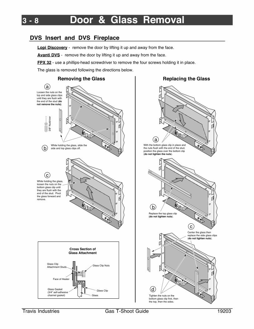
DVS Insert and DVS Fireplace
Lopi Discovery - remove the door by lifting it up and away from the face.
Avanti DVS - remove the door by lifting it up and away from the face.
FPX 32 - use a phillips-head screwdriver to remove the four screws holding it in place.
The glass is removed following the directions below.
AAA
Cross Section of Glass Attachment
AAA
AAAAAAAAA
Glass
Glass Gasket (3/4" self-adhesive channel gasket)
Glass Clip
Glass Clip Attachment Studs
Face of Heater
Glass Clip Nuts
Loosen the nuts on the top and side glass clips until they are flush with the end of the stud (do not remove the nuts).
a
3/8"
Nut
driv
er
b
While holding the glass, loosen the nuts on the bottom glass clip until they are flush with the end of the stud. Pivot the glass forward and remove.
Tighten the nuts on the bottom glass clip first, then the top, then the sides.
Removing the Glass
AAAAAAAAAAAAAAAAAAAAAAAAAAAAAAAAAAAAAAAAAAAAAAAAAAAAAAAAAAAAAAAAAAAAAAAA
AAAAAAAAAAAAAAAAAAAAAAAAAAAAAAAAAAAAAAAAAAAAAAAAAAAAAAAAAAAAAAAAAAAAAAAA
While holding the glass, slide the side and top glass clips off.
c
Replacing the Glass
AAAAAAAAAAAAAAAAAAAAAAAAAAAAAAAAAAAAAAAAAAAAAAAAAAAAAAAAAAAAAAAAAAAAAAAAAAAAAAAA
With the bottom glass clip in place and the nuts flush with the end of the stud, position the glass over the bottom clip (do not tighten the nuts).
AAAAAAAAAAAAAAAAAAAAAAAAAAAAAAAAAAAAAAAAAAAAAAAAAAAAAAAAAAAAAAAAAAAAAAAAAAAAAAAAA
Replace the top glass clip (do not tighten nuts).
AAAAAAAAAAAAAAAAAAAAAAAAAAAAAAAAAAAAAAAAAAAAAAAAAAAAAAAAAAAAAAAAAAAAAAAAAAAAAAAAA
Center the glass then replace the side glass clips (do not tighten nuts).
a
b
c
d
Burner Pan Components 4 - 1
Travis Industries Gas T-Shoot Guide 19203
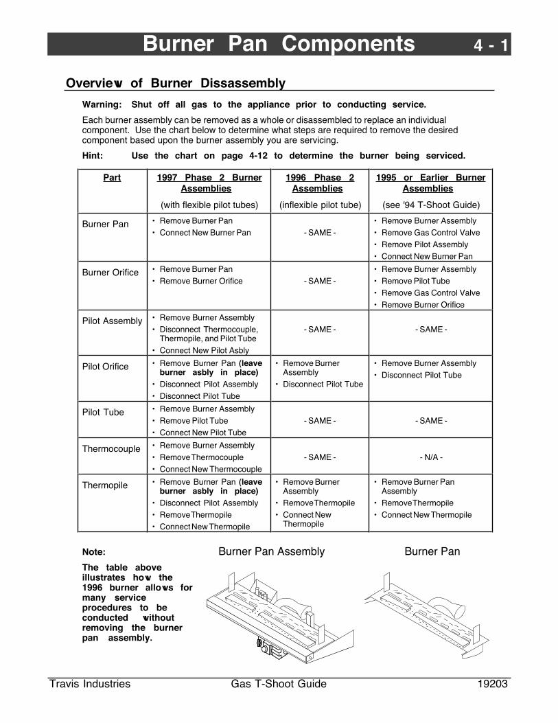
Overview of Burner Dissassembly
Warning: Shut off all gas to the appliance prior to conducting service.
Each burner assembly can be removed as a whole or disassembled to replace an individualcomponent. Use the chart below to determine what steps are required to remove the desiredcomponent based upon the burner assembly you are servicing.
Hint: Use the chart on page 4-12 to determine the burner being serviced.
Part 1997 Phase 2 BurnerAssemblies
(with flexible pilot tubes)
1996 Phase 2Assemblies
(inflexible pilot tube)
1995 or Earlier BurnerAssemblies
(see '94 T-Shoot Guide)
Burner Pan ¥ Remove Burner Pan¥ Connect New Burner Pan - SAME -
¥ Remove Burner Assembly¥ Remove Gas Control Valve¥ Remove Pilot Assembly¥ Connect New Burner Pan
Burner Orifice ¥ Remove Burner Pan¥ Remove Burner Orifice - SAME -
¥ Remove Burner Assembly¥ Remove Pilot Tube¥ Remove Gas Control Valve¥ Remove Burner Orifice
Pilot Assembly ¥ Remove Burner Assembly¥ Disconnect Thermocouple,
Thermopile, and Pilot Tube¥ Connect New Pilot Asbly
- SAME - - SAME -
Pilot Orifice ¥ Remove Burner Pan (leaveburner asbly in place)
¥ Disconnect Pilot Assembly¥ Disconnect Pilot Tube
¥ Remove BurnerAssembly
¥ Disconnect Pilot Tube
¥ Remove Burner Assembly¥ Disconnect Pilot Tube
Pilot Tube ¥ Remove Burner Assembly¥ Remove Pilot Tube¥ Connect New Pilot Tube
- SAME - - SAME -
Thermocouple ¥ Remove Burner Assembly¥ Remove Thermocouple¥ Connect New Thermocouple
- SAME - - N/A -
Thermopile ¥ Remove Burner Pan (leaveburner asbly in place)
¥ Disconnect Pilot Assembly¥ Remove Thermopile¥ Connect New Thermopile
¥ Remove BurnerAssembly
¥ Remove Thermopile¥ Connect New
Thermopile
¥ Remove Burner PanAssembly
¥ Remove Thermopile¥ Connect New Thermopile
Note:
The table aboveillustrates how the1996 burner allows formany serviceprocedures to beconducted withoutremoving the burnerpan assembly.
Burner Pan Assembly Burner Pan

4 - 2 Burner Pan Components
Travis Industries Gas T-Shoot Guide 19203
Burner Assembly Removal - BVM, DVS & DVM Burners
Warning Shut off all gas to the appliance prior to conducting service.
Access the firebox (see Door & Glass Removal if necessary).
Make sure the two tabs slide over the side of the burner pan on both sides.
Rear Log
Shelf
Position the shelf so the back edges of the shelf and burner pan are flush.
The rear log shelf slides on and off the burner pan assembly
Burner Pan Assembly
Rear Log Shelf
NOTE: When installed, the log shelf must maintain a parallel 3/8Ó gap to the burner pan.
1 Remove the logshelf following thedirections above.
2 Remove the gasinlet following thedirections to theright.
3 Remove theburner panfollowing thedirections to theright.
The gas inlet on freestanding stoves protrudes from the rear panel.
AAAAAAAAAAAAAAAAAAAAAAAAAAAAAAAAAAAAAAAA
A
AAA
A
AA
AAAAAAAAAAAA
Disconnect the gas supply from the gas inlet and turn the pipe counter-clockwise with a pipe wrench.
StovesThe gas inlet on inserts is on the left side - either facing to the rear or to the left.
Inserts DVS FireplacesDisconnect the flex tube from the fitting on the gas control valve.
Gas Control Valve
PILOT ADJ
TOL PI
ON
OFF
3/8" M.P.T to 1/2" O.D. Fitting
Flex Tube
3/4"
Wre
nch
7/8"
Wre
nch
Hold the fitting in place while unscrewing the flex tube.
Remove the burner pan, tilting it forward to allow the gas control valve to clear the front of the heater.
aDisconnect the brown and red wires from the on/off switch.
Disconnect the six nuts used to attach the burner pan.
Disconnect the orange wire from the burner pan to the piezo igniter.
d
b
c
7/16Ó Socket Wrench(use an
extension)

Burner Pan Components 4 - 3
Travis Industries Gas T-Shoot Guide 19203
Burner Assembly Removal - DVL Burners
Warning Shut off all gas to the appliance prior to conducting service.
Heritage Bay Only
Remove the control panel following the directions below.
Remove the four screws holding the control panel in place.
Lay the control panel face down so the area behind it may be accessed.
Control Panel
Open the Door on the pedestal.
1/4" Nutdriver
Access the firebox and remove the burner pan following the directions below
Remove the burner pan, tilting it forward to allow the gas control valve to clear the front of the heater.
7/16Ó Socket
a
e
Disconnect the brown and red wires from the on/off switch.
Disconnect the six nuts used to attach the burner pan.
Burner Pan
Disconnect the orange wire from the burner pan to the piezo igniter.
d
b
cHold the fitting in place with the 3/4" wrench while unscrewing the flex tube.
3/4"
Wre
nch
7/8"
Wre
nch

4 - 4 Burner Pan Components
Travis Industries Gas T-Shoot Guide 19203
Burner Pan Removal - BVM, DVS & DVM Burners
Remove the burner pan following the directions above.
Make sure the two tabs slide over the side of the burner pan on both sides.
Rear Log
Shelf
Position the shelf so the back edges of the shelf and burner pan are flush.
The rear log shelf slides on and off the burner pan assembly
Burner Pan Assembly
Rear Log Shelf
NOTE: When installed, the log shelf must maintain a parallel 3/8Ó gap to the burner pan.
Slide the burner pan to the left until the fixed shutter disengages from the orifice. Place the burner pan aside.
Burner Pan
Burner Pan Box
Fixed shutter
Orifice
c
Remove the two screws holding the burner box front in place.
Remove the burner box front.
a
1/4" Nutdriver
Rotate the burner pan upwards.
b

Burner Pan Components 4 - 5
Travis Industries Gas T-Shoot Guide 19203
Burner Pan Removal - DVL Burners
Remove the burner pan following the directions above.
Slide the burner pan to the left until the fixed shutter disengages from the orifice. Place the burner pan aside.
Fixed shutter
Orifice
Burner Pan
Burner Pan Box
Rotate the burner pan upwards.
Removethe burner box front and rear log shelf.
Standard Screwdriver
Burner Box Front
a
b
c
Rear Log Shelf (when replacing, make sure to slide it all the way back).

4 - 6 Burner Pan Components
Travis Industries Gas T-Shoot Guide 19203
Burner Orifice Removal
Follow the directions below to remove the orifice. When re-installing the orifice, apply thread sealantto the threads and tighten in place with a 1/2" open end wrench.
Push the adjustable shutter to the left, off the orifice (be careful not to bend the shutter linkage).
1/2"
Wre
nch
Slide the adjustable shutter down, away from the orifice.
Remove the spring
Use a 1/2Ó open end wrench to unscrew the orifice.
There is usually a number stamped here to indicate orifice size.
Make sure to keep any sealant or debris from entering the orifice and blocking gas flow.
Apply thread sealant to the new orifice prior to installation.
Adjustable Shutter
Orifice
Shutter Linkage
a b c
d e f
Burner Pan Components 4 - 7
Travis Industries Gas T-Shoot Guide 19203
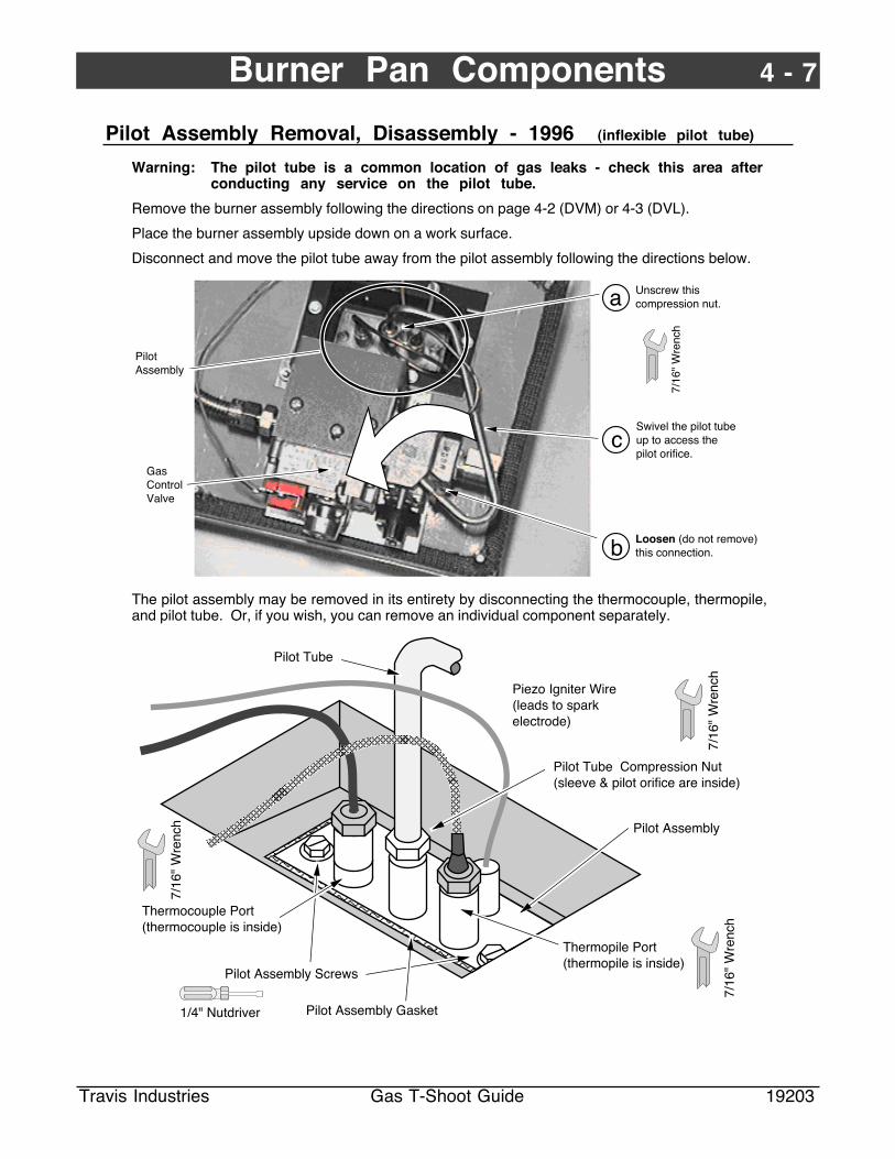
Pilot Assembly Removal, Disassembly - 1996 (inflexible pilot tube)
Warning: The pilot tube is a common location of gas leaks - check this area afterconducting any service on the pilot tube.
Remove the burner assembly following the directions on page 4-2 (DVM) or 4-3 (DVL).
Place the burner assembly upside down on a work surface.
Disconnect and move the pilot tube away from the pilot assembly following the directions below.
Loosen (do not remove) this connection.
Gas Control Valve
7/16
" W
renc
h
Pilot Assembly
Unscrew this compression nut.
Swivel the pilot tube up to access the pilot orifice.
a
b
c
The pilot assembly may be removed in its entirety by disconnecting the thermocouple, thermopile,and pilot tube. Or, if you wish, you can remove an individual component separately.
AAAAAAAAAAAAAAAAAAAAAAAAAAAAAAAAAAAAAAAAAAAAAAAAAAAAAAAAAAAA
AAAAA
AAAAAA
AAAAAAAA
AAAAAAAAAAAA
AAAAAAAA
Thermocouple Port (thermocouple is inside)
7/16
" W
renc
h
1/4" Nutdriver Pilot Assembly Gasket
Piezo Igniter Wire (leads to spark electrode)
Pilot Assembly
Pilot Assembly Screws
Pilot Tube Compression Nut (sleeve & pilot orifice are inside)
Pilot Tube
Thermopile Port(thermopile is inside)
7/16
" W
renc
h
7/16
" W
renc
h

4 - 8 Burner Pan Components
Travis Industries Gas T-Shoot Guide 19203
Pilot Assembly Removal, Disassembly - 1997 (flexible pilot tube)
Warning: The pilot tube is a common location of gas leaks - check this area afterconducting any service on the pilot tube.
Remove the burner pan (not the entire burner assembly) following the directions above.
The pilot assembly may be removed in its entirety by disconnecting the thermocouple, thermopile,pilot tube, and piezo igniter wire. Or, if you wish, you can remove an individual component separately.
AAAAAAAAAAAAAAAAAAAAAAAAAAAAAAAAAAAAAAAAAAAAA
AAAAAAAAAAAAAAAAAAAAAAAAAAAAAAAAAAAAAAAAAAAAAAAAAAAAAA
1/4"
Nut
driv
er
Pilot Assembly
To remove the pilot assembly, remove the two screws holding the assembly in place. Then pull up on the pilot hood until the assembly can be accessed from the bottom.
IMPORTANT NOTE:Make sure the pilot asembly does not rotate while detaching components from the pilot assembly. Insert a standard screwdriver between the components or use a vice-grip toclamp the assembly in place.
AAAAAAAAAA
AAAAAAAAAAAAAAAAAAAAAAAAAAAAAAAAAAAAAAAAAAAAAAAAAA
AAAAAAAAAAAAAAAAAAAAAAAAAAAAAAAAAAAAAAAAAAAAAAAAAAAAAAAAAAAA
AAAAAAAAAAAAAAAAAAAAAAAAAAAAAAAAAAAAAAAA
AAAAAAAAAAAAAAAAAAAAA
AAAAAAAAAAAAAAAAAAAAAAAAAAAAAAAAAAAAAAAAAAAAA
AAAAAAAAAAAAAAAAAAAAAAAAAAAAAAAAAAAAAAAAAAAAAAAAAAAAAA
AAAAAAAAAAAAAAAAAAAAAAAAAAAAAAAAAAAAAAAA
Do not kink or excessively bend the pilot tube - this may lead to leaks.
Thermocouple(remove from the bottom)
Piezo Igniter Wire (to disconnect, remove the orange wire leading to the piezo igniter)
Pilot Tube Nut Pilot orifice is inside(remove from the bottom)
Thermopile(remove from the bottom)
7/16
" W
renc
h
Spark Electrode(part of the pilot assembly)
7/16" Wrench
Pilot Hood
7/16
" W
renc
h Disconnect
Connect

Burner Pan Components 4 - 9
Travis Industries Gas T-Shoot Guide 19203
Pilot Orifice Removal
Warning: The pilot tube connections are a common location for gas leaks. Takespecial care on these gas connections and leak test at both connectionsafter installing.
1996 or Earlier Burners
The burner pan must be remoed prior toremoving the pilot orifice. Disconnect thecompression nut with a 7/16" open endwrench and move the pilot tube away from thepilot assembly (see ÒPilot Assembly RemovalÓon page 4-7). You may need to tap the burnerpan to dislodge the pilot orifice.
Pilot Orifice
Compression Nut
Compression Sleeve
Pilot Tube Port on Pilot Assembly
Pilot TubeMake sure the pilot tube inserts into the pilot orifice.
NG vs. LP Orifice
1997 or Later Burners
Disconnect the compression nut with a 7/16"open end wrench and move the pilot tubeaway from the pilot assembly (see ÒPilotAssembly RemovalÓ on page 4-8).
Make sure the pilot orifice fits over the compression sleeve.
AAAAAAAAAAA
AAAAAAAAAAAAAAAAAAAAAAAAAAAAAAAAAAAAAAAA
AAAAAAAAAAAAAAAAAAAAAAAAAAAAAAAAAAAAAAAAAAAAAAAAAAAAAAAAAAAA
AAAAAAAAAAAAAAAAAAAAAAAAAAAAAAAAAAAAAAAAAAAAAAAA
Pilot Tube
Compression Nut
Compression Sleeve
Pilot Orifice
Pilot Tube Port on Pilot Assembly
Pilot Assembly
1 6
P
L
LP Pilot Orifice
NG Pilot Orifice
2 1
N

4 - 10 Burner Pan Components
Travis Industries Gas T-Shoot Guide 19203
Thermopile Removal
Refer to the section on pilot assembly removal (for 1997 or later models see page 4-8, 1996 or earliersee page 4-7). Use a 7/16" open end wrench to remove the thermopile from the pilot assembly.
Disconnect the theropile from the gas control valve following the instructions below.
Gas Control Valve
PILOT ADJ
VE
NT
TOL PI
ON
OFF
HI
LO
AAAAAAAAAAA
Standard Screwdriver
Red Thermopile Wire
White Thermopile Wire
Use a standard screwdriver to remove the two thermopile wires from the gas control valve.
Thermocouple Removal
Remove the burner pan (for 1997 or later models see page 4-2, 1996 or earlier see page 4-1).
Place the burner pan upside down and remove the thermocouple with a 7/16" open end wrench (seethe illustration on page 4-7 for the location of the thermocouple).
Disconnect the thermocouple wire from the gas control valve following the instructions below.
PILOT ADJ
VE
NT
TO L PI
ON
OFF
HI
LO
Thermocouple Connector
3/8"
Wre
nch
B-Vents Only
Copper Tube
Use a 3/8" open end wrench to remove the thermocouple wire.

Burner Pan Components 4 - 11
Travis Industries Gas T-Shoot Guide 19203
Spark Electrode Removal
The spark electrode is incorporated into the pilot assembly - replace the entire assembly (for 1997 orlater models see page 4-8, 1996 or earlier see page 4-7).
Piezo Igniter
To remove the piezo igniter, follow the directions below.
Slide the piezo igniter forward
Remove the orange piezo wire from the pizo igniter.
Unscrew the nut - usually this can be done by hand, otherwise use an 1-1/16" open end wrench.
On/Off Switch
Remove the on/off switch following the directions below.
AAAAAA
AAAA
AAAAAA
Depress the locking tabs on the back of the on/off switch. Use a screwdriver, if necessary, to gain enough leverage.
AAAA
AAAAAAAA
a
cb
Carefully thread the on/off switch out, making sure not to disconnect or damage the wiring.
Note the orientation of the wiring on back of the switch before detaching the wires.
Warning When replacing the switch, make sure to secure the wires so they do not contact thebottom of the burner pan and melt.

4 - 12 Burner Pan Components
Travis Industries Gas T-Shoot Guide 19203
Burner Pan Parts
Phase 2 Burners
96 BVM 96 DVM 97 DVS 96 DVLBurner description Flex tube comes off
valve, goes to manifoldinside burner assembly
Direct vent mediumFlex tube comes offvalve, goes to manifoldinside burner assembly
Dvs insert & fpFlex tube comes off valve,goes to manifold insideburner assembly
Elbow comes off gas controlvalve, goes to 1/4" pipe routedto manifold inside burner pan
Compatability Avanti B-Vent (1996 +)700 B-Vent (1996 +)Spirit B-Vent (1996 +)Spirit Insert (1996 +)Heritage Insert (1997 +)
Avanti DV (1996 +)700 DV (1996 +)Spirit DV (1996 +)
DVS InsertDVS FireplaceAvanti DV (1995 only)
36-DVHeritage Bay DVHeritage Bay B-Vent
NG Max BTU/Hour 40,000 38,500 31,000 40,000LP Max BTU/Hour 38,000 36,500 31,000 40,000NG Burner Assembly 98900792 98900793 98900794
98900741 (95 Avanti DV)98500811 (for 95 36-DV)98500814 (36-DV, Her DV)98500816 (Her BV)
LP Burner Assembly 98900790 98900791 9890079598900740 (95 Avanti DV)
98500810 (for 95 36-DV)98500815 (36-DV, Her DV)98500817 (Her BV)
Gas Valve (NG) 97300130 97300130 97300130 97300130Gas Valve (LP) 97300120 97300120 97300120 97300120Regulator (NG) 98900733 98900733 98900733 98900733Regulator (LP) 98900734 98900734 98900734 98900734Thermocouple Interupt 99300660 N/A N/A 99300660 (Her Bay BV Only )NG Burner Orifice #31 98900792 #32 98900606 #37 98900713 #31 98900605LP Burner Orifice #49 98900607 #50 98900608 .0625 98900717 #49 98900607Pilot Orfice (NG) .021 91001505 .021 91001505 .021 91001505 .021 91001505Pilot Orifice (LP) .016 91001506 .016 91001506 .016 91001506 .016 91001506Thermocouple 98900748 98900748 98900748 98900748Thermopile 98900752 98900752 98900752 98900752Pilot Assembly (NG) 98900600 98900600 98900600
91001501 (95 Avanti DV)9890060091001501 (95 36-DV)
Pilot Assembly (LP) 98900602 98900602 9890060291001500 (95 Avanti DV)
9890060291001500 (95 36-DV)
Pilot Tube 91001508 91001508 9100150898900753A (95 Avanti DV)
9100150891001507 (95 36-DV)
Front LogRear LogLeft TwigRight TwigEmbers
9720033197200330972003339720033297200334
9720033197200330972003339720033297200334
9720033197200330972003339720033297200334
9730010897300106973001129730011097300114
Phase 1 Burners (see 1994 Gas Troubleshooting Guide for Details)
93 BV 94 BV 95 BVBurner description Two burner orifices coming
off manifold that connects togas control valve. Replacewith 94 BV
One burner orifice coming off manifoldthat connects to gas control valve
Orifice directly off gas controlvalve
Compatability 700 NG (93 only)300 GS (93 only)
700 NG (94 only)300 GS (94 only)700 B-Vent (300 GS) (1995 only)Spirit B-Vent - 300 GS (1995 only)Spirit Bay Insert - 300 GI (1995 only)
Avanti B-Vent (1995 only)
NG Max BTU/Hour 31,000 31,000 31,000LP Max BTU/Hour N/A 31,000 31,000NG Burner Assembly ---------------> 98900706 98900737LP Burner Assembly ---------------> 98900708 98900736Gas Valve (NG) 98900727 98900727 98900727Gas Valve (LP) 98900716 98900716 98900716NG Burner Orifice # 53 Front #43 Rear #37 98900713 #37 98900713LP Burner Orifice N/A .0625 98900717 .0625 98900717Pilot Orfice (NG) .021 91001505 .026 .026Pilot Orifice (LP) N/A .016 91001506 .016 91001506Thermocouple N/A N/A N/AThermopile 98900752 98900752 98900752Pilot Assembly (NG) 98900726 98900726 98900726Pilot Assembly (LP) 98900715 98900715 98900715Pilot Tube 91001508 91001508 91001508Logs Not Available Not Available Not Available

Blower Components 5 - 1
Travis Industries Gas T-Shoot Guide 19203
Avanti Stove (DV & B-Vent) Blower Removal
Warning Make sure the power cord is disconnected prior to conducting service.
Warning Shut off gas to the heater - you may need to disconnect the gas linedepending upon the heater location and the type of gas connection.
1 Remove the rear panel.
AAAAA A
AAAAAAA
AAAAAAAAAAAAAAAAAAAAAAAAAAAAAAAAAAAAAAAAAAAAA
AAAAAAAAAAAAAAAAAAAAAAAAAAAAAAAAAAAA
AAAAAAAAAAAAAAAAAAAAAAAAAAAAAAAAAAAAAAAAAAAAAAAAAAAAAAAAAAAAAAAAAAAAAAAAAAAAAAAAAAAA
AAAAAAAAAAAAAAAAAAAAAAAAAAAAAAAAAAAAAAAA
A
A
AA
A
AAA
A
AAAA
A
AAAAAAAAAAAAAAAAAAAAAAAAAAAAAAAAAAAAAAAAAAAAAAAAAAAAAAAAAAAAAAAAAAAAAAAAAAAAAAAAAAAAAAAAAA
AAAA
A
A
A
A
A
A
AAAA
AA
A
A
AA
AAAA
AAAA
AAAAAAAA
AA
AAA
AA
AAAAAAA
AA
Rear Panel
Disconnect the molex connector leading from the power cord.
AAAAAAAA
5/16
" N
utdr
iver
Molex Connection
AAA
AAAA
AA
AAAAAAAAAA
Remove the strain relief
Disconnect the wires leading to the on/off switch.
2 Disconnect the side panels from the baseplate.Slide the side and top panels up and prop themin place to access the blower area.
3 With the left rear of the heater exposed, theblower assembly can be accessed. Follow thedirections on page 5-5 (A20 Blower AssemblyRemoval & Disassembly) to remove the blowerfrom the heater. 7/
16"
Wre
nch
Standard Screwdriver
Use a 2x4 to prop up the top and sides.

5 - 2 Blower Components
Travis Industries Gas T-Shoot Guide 19203
Avalon 700 (B-Vent & DV) Blower Removal
Warning Make sure the power cord is disconnected prior to conducting service.
Warning Shut off gas to the heater - you may need to disconnect the gas linedepending upon the heater location and the type of gas connection.
Note: If the Avalon 700 was installed as an insert, remove it from the fireplace (remove thepanels, glass and logs first to prevent damage while moving the insert).
1 Remove the two screws on the cover platearound the gas inlet. Unscrew the ninescrews holding the rear panel in place.
5/16
" N
utdr
iver
Cover Plate
2 Swing the rear panel to the left anddisconnect the molex connector leadingfrom the power cord.
Remove the Molex Connection
3 Remove the nuts holding the left side panelto the baseplate.
Remove these nuts (left side only)
3/8"
Wre
nch
4 Loosen the nuts holding the left sidepanel to the convection top (three turns).
Loosen these nuts (left side only)
3/8"
Wre
nch
5 Remove the left side panel by pushing itbackwards and sliding it down (NOTE: thetop panel has an ÒLÓ shaped notch forattachment).
6 With the left rear of the heater exposed, theblower assembly can be accessed. Followthe directions on page 5-5 (A20 BlowerAssembly Removal & Disassembly) toremove the blower from the heater.

Blower Components 5 - 3
Travis Industries Gas T-Shoot Guide 19203
Lopi Spirit (B-Vent & DV) Blower Removal
Warning Make sure the power cord is disconnected prior to conducting service.
Warning Shut off gas to the heater - you may need to disconnect the gas linedepending upon the heater location and the type of gas connection.
1 Remove the two screws on the cover platearound the gas inlet. Unscrew the ninescrews holding the rear panel in place.
5/16
" N
utdr
iver
Cover Plate
2 Swing the rear panel to the left anddisconnect the molex connector leadingfrom the power cord.
Remove the Molex Connection
3 Remove the nuts holding the left sidepanel to the baseplate.
Remove these nuts (left side only)
3/8"
Wre
nch
4 Remove the nuts holding the left sidepanel to the convection top.
Remove these nuts (left side only)
3/8"
Wre
nch
5 Remove the left side panel by lifting up onthe top convection panel and lifting thepanel free of the base.
6 With the left rear of the heater exposed,the blower assembly can be accessed.Follow the directions on page 5-5 (A20Blower Assembly Removal & Disassembly)to remove the blower from the heater.

5 - 4 Blower Components
Travis Industries Gas T-Shoot Guide 19203
Avanti Insert (DV or B-V) Blower Removal
Warning Make sure the power cord is disconnected prior to conducting service.
Warning Shut off all gas and disconnect the gas line from the heater.
1 Remove the insert from the fireplace (remove the panels, glass and logs first to preventdamage while moving the insert).
2 With the left rear of the heater exposed, the blower assembly can be accessed. Followthe directions on page 5-5 (A20 Blower Assembly Removal & Disassembly) to remove theblower from the heater.
Heritage Bay Insert Blower Removal
Warning Make sure the power cord is disconnected prior to conducting service.
Warning Shut off all gas and disconnect the gas line from the heater.
1 Remove the insert from the fireplace (remove the panels, glass and logs first to preventdamage while moving the insert).
2 With the left rear of the heater exposed, the blower assembly can be accessed. Followthe directions on page 5-5 (A20 Blower Assembly Removal & Disassembly) to remove theblower from the heater.
Sprit Bay Insert Blower Removal
Warning Make sure the power cord is disconnected prior to conducting service.
Warning Shut off all gas and disconnect the gas line from the heater.
1 Remove the insert from the fireplace (remove the panels, glass and logs first to preventdamage while moving the insert).
2 With the left rear of the heater exposed, the blower assembly can be accessed. Followthe directions on page 5-5 (A20 Blower Assembly Removal & Disassembly) to remove theblower from the heater.

Blower Components 5 - 5
Travis Industries Gas T-Shoot Guide 19203
A20 Blower Assembly Removal & Dissassembly
1 Disconnect the wires leadingto the blower. Remove thefour nuts holding the blowerassembly in place.
Disconnect the two wires leading to the blower. NOTE: orientation does not matter while reinstalling.
2 Remove the four nutsholding the blower in place.Slide the blower out.
Remove the four nuts holding the blower in place.11/32" Nutdriver
Slide the blower out to the side.
3 When re-installing, make sureto position the bracketscorrectly behind the blowerassembly.
AA
Stud Plate
Rubber Grommet & Bushing
Mounting Plate on Heater
Washer
Nut
Blower Plate

5 - 6 Blower Components
Travis Industries Gas T-Shoot Guide 19203
DVS Insert Blower Removal
Warning Make sure the power cord isdisconnected prior toconducting service.
Warning Shut off all gas anddisconnect the gas line fromthe heater.
1 Remove the insert from the fireplace(remove the panels, glass and logs first toprevent damage while moving the insert).
2 To disonnect the vent, disconnect themanifold from the heater (see the illustrationto the right).
3 Remove the left side cover plate (see theillustration below to the left).
4 Remove the four nuts holding the blower inplace. Then remove the stud plate behindthe blower on the right side (see theillustration below to the right).
1/4"
Nut
driv
er Remove the three screws holding the plate in place.
These nuts hold the blower assembly in place.
5 Slide the blower to the left, disconnect theelectrical connection, then slide the blowerout.
Remove the four bolts inside the firebox.
7/16Ó Socket
5/16
" N
utdr
iver
Remove the three screws holding the convection top to the insert.
Convection Top Manifold
Slide the manifold back.
NOTE: when installing the manifold, make sure the gaskets sealing the inlet and exhaust ducts are in place. If a gasket is loose, use high-temperature silicone to secure it to the manifold.
Shim the manifold legs if installing into a fireplace with a raised hearth.
Remove the four nuts holding the blower in place.11/32" Nutdriver
Slide the blower out to the side.
6 When re-installing, make sure to positionthe brackets correctly behind the blowerassembly.
AA
Stud Plate
Rubber Grommet & Bushing
Mounting Plate on Heater
Washer
Nut
Blower Plate

Blower Components 5 - 7
Travis Industries Gas T-Shoot Guide 19203
DVS Fireplace Blower Removal
Warning Make sure power isdisconnected to theheater prior toconducting service -remove the fuse ordisable the breakerservicing the heater.
Warning Shut off all gas anddisconnect the gas linefrom the heater.
1 Remove the faceplate of the fireplace(see page 3-5).
2 Remove the burner pan assembly (seepage 4-2).
1/4"
Nut
driv
er
Remove the ten screws holding the plate in place.
3 Remove the cover plate at the back of the firebox (see the illustration above).
4 Remove the heat shield behind the firebox.
1/4"
Nut
driv
er
Remove the three screws holding the heat shield in place.
5 Remove the two nuts (and washers) on theright side of the blower.
6 Remove the right side blower heat shield.
Remove the two nuts (and washers) holding the blower and right side heat shield in place.
11/3
2" W
renc
h
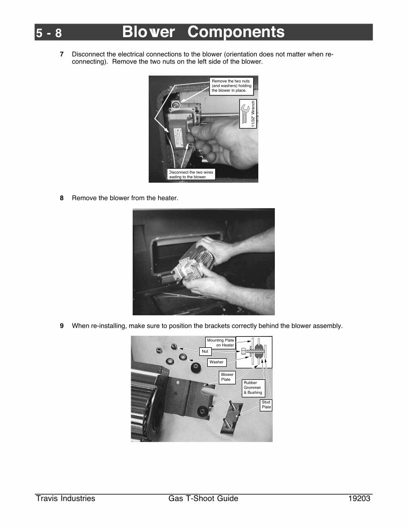
5 - 8 Blower Components
Travis Industries Gas T-Shoot Guide 19203
7 Disconnect the electrical connections to the blower (orientation does not matter when re-connecting). Remove the two nuts on the left side of the blower.
Remove the two nuts (and washers) holding the blower in place.
11/3
2" W
renc
h
Disconnect the two wires leading to the blower.
8 Remove the blower from the heater.
9 When re-installing, make sure to position the brackets correctly behind the blower assembly.
AA
Stud Plate
Rubber Grommet & Bushing
Mounting Plate on Heater
Washer
Nut
Blower Plate

Blower Components 5 - 9
Travis Industries Gas T-Shoot Guide 19203
FPX 36-DV Blower Removal
Warning Make sure power is disconnected tothe heater prior to conducting service -remove the fuse or disable the breakerservicing the heater.
Warning Shut off gas to the heater - you mayneed to disconnect the gas linedepending upon the heater locationand the type of gas connection.
1 Remove the faceplate of the fireplace (see page 3-5).
2 Disconnect the flex tube from the gas control valve.
3 Remove the nuts holding the blower in place.
Hold the fitting in place with the 3/4" wrench while unscrewing the flex tube with a 7/8Ó wrench.
3/4"
Wre
nch
7/8"
Wre
nch
Gas Control Valve
Fitting
Flex Tube
7/16Ó Socket
These nuts hold the blower in place.
7/16Ó Socket
These nuts hold the blower in place.
4 Move the blower to the left of the gas control valve and thread it out of the appliance.
5 Disconnect the wires leading to the blower (orientation does not matter when re-installing).
6 When re-installing, make sure the rubbergrommet fits into the bracket. Place thewasher over the grommet and tighten thenut just enough to slightly compress thegrommet.
Bracket (on blower)
Rubber Grommet
Washer
Nut

5 - 10 Blower Components
Travis Industries Gas T-Shoot Guide 19203
Heritage Bay Blower Removal
Warning Make sure the power cord is disconnected prior to conducting service.
Warning Shut off gas to the heater - you may need to disconnect the gas linedepending upon the heater location and the type of gas connection.
1 Remove the four nuts underneath theblower.
2 Slide the blower assembly out. You maywish to remove the stud bracket andrubber grommets from the blowerassembly to better facilitate removal.
Remove these nuts
11/3
2" N
utdr
iver
Blower Assembly
Stud Bracket
3 Disconnect the wires from the blower. 4 When re-installing, make sure the grommetslides into make sure the stud bracket isfed through from above with a washerbetween it and the rubber grommet.
Stud Bracket
Washer
Rubber Grommet
Nut
The blower assembly inserts into this groove.

Blower Components 5 - 11
Travis Industries Gas T-Shoot Guide 19203
Blower Rheostat Removal
Warning Make sure the power cord is disconnected prior to conducting service.
Warning Shut off gas to the heater - you may need to disconnect the gas linedepending upon the heater location and the type of gas connection.
Remove the rheostat following the directions below.
Pull the knob off.
Disconnect the wires.
Unscrew this nut.
11/1
6" W
renc
h
NOTE: this tab fits into the hole on the mounting bracket.
Blower Snap Disk Removal - Heritage Bay Stove & FPX 36-DV
Warning Make sure the power cord is disconnected prior to conducting service.
Warning Shut off gas to the heater - you may need to disconnect the gas linedepending upon the heater location and the type of gas connection.
Heritage Bay Only
Remove the control panelfollowing the directions to theright.
Remove the four screws holding the control panel in place.
Lay the control panel face down so the area behind it may be accessed.
Control Panel
Open the Door on the pedestal.
1/4" Nutdriver
The blower snap disk is located underneath the burner pan on the right side. Disconnect the black &white wires from the snap disk (orientation does not matter when re-connecting).
Blower Snap Disk
Phillips Screwdriver
610046T-O-D 60T12
9305F120-10F
Remove the snap disk from its bracket below the firebox.

5 - 12 Blower Components
Travis Industries Gas T-Shoot Guide 19203
Blower Snap Disk Removal - All Models Except Heritage Bay Stove & 36-DV
Warning Make sure the power cord is disconnected prior to conducting service.
Warning Shut off gas to the heater - you may need to disconnect the gas linedepending upon the heater location and the type of gas connection.
Inserts
1 Remove the insert from the fireplace (remove the panels, glass and logs first to preventdamage while moving the insert).
2 With the right rear of the heater exposed, the blower snap disk may be removed from itsmounting bracket. Disconnect the black & white wires from the snap disk (orientationdoes not matter when re-connecting).
Blower Snap Disk
Phillips Screwdriver
610046T-O-D 60T12
9305F120-10F
Remove the snap disk from its bracket behind the firebox.
Stoves
1 Remove the rear panel (see the instructions under ÒBlower RemovalÓ for the model beingserviced - pages 5-1 through 5-3).
2 With the right rear of the heater exposed, the blower snap disk may be removed from itsmounting bracket. Disconnect the black & white wires from the snap disk (orientationdoes not matter when re-connecting).
Blower Snap Disk
Phillips Screwdriver
610046T-O-D 60T12
9305F120-10F
Remove the snap disk from its bracket behind the firebox.
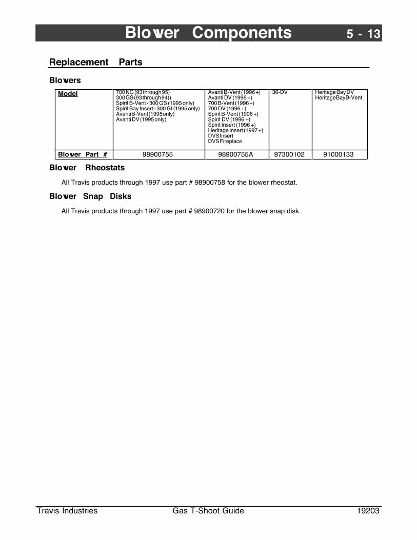
Blower Components 5 - 13
Travis Industries Gas T-Shoot Guide 19203
Replacement Parts
Blowers
Model 700 NG (93 through 95)300 GS (93 through 94))Spirit B-Vent - 300 GS (1995 only)Spirit Bay Insert - 300 GI (1995 only)Avanti B-Vent (1995 only)Avanti DV (1995 only)
Avanti B-Vent (1996 +)Avanti DV (1996 +)700 B-Vent (1996 +)700 DV (1996 +)Spirit B-Vent (1996 +)Spirit DV (1996 +)Spirit Insert (1996 +)Heritage Insert (1997 +)DVS InsertDVS Fireplace
36-DV Heritage Bay DVHeritage Bay B-Vent
Blower Part # 98900755 98900755A 97300102 91000133
Blower Rheostats
All Travis products through 1997 use part # 98900758 for the blower rheostat.
Blower Snap Disks
All Travis products through 1997 use part # 98900720 for the blower snap disk.

Gas Service Manual
Travis Industries Gas T-Shoot Guide 19203
Gas Service Manual
Copyright 1997
Travis Industries, Inc.