
Gas Safety Management Plan Section B · Version 5.00 – 02 August 2013 Gas Safety Management Plan...
127
Version 5.00 – 02 August 2013 Gas Safety Management Plan (Section B) Produced to meet the requirements of the Gas Safety (Management) Regulations (Gas Safety Management Plan (Section A) covers the requirements of the Gas Safety (Installation and Use) Regulations)
Transcript of Gas Safety Management Plan Section B · Version 5.00 – 02 August 2013 Gas Safety Management Plan...

Version 5.00 – 02 August 2013
Gas Safety Management Plan (Section B) Produced to meet the requirements of the Gas Safety (Management) Regulations (Gas Safety Management Plan (Section A) covers the requirements of the Gas Safety (Installation and Use) Regulations)

i
Foreword The Management of Health and Safety at Work Regulations requires employers to put in place arrangements for the effective planning, organisation, control, monitoring and review of the preventive and protective measures necessary to ensure health and safety at work is properly managed and to establish, where necessary, appropriate procedures to be followed in the event of serious and/or imminent danger. This document contains the template for the Gas Safety Management Plan (Section B) for Establishments on the Ministry of Defence (MOD) Estate. Implementation of this plan will enable the Establishment to demonstrate compliance with the Gas Safety (Management) Regulations (GS(M)R) for working on and maintaining gas systems. Note: Section ‘A’ of the Gas Safety Management Plan supports the requirements under the Gas Safety (Implementation and Use) Regulations The MOD owns the gas supply network at [Insert Name of Establishment]. In order to meet MOD responsibilities as a Public Gas Transporter (PGT) a Safety Case1 has been compiled in accordance with the GS(M)R. This Gas Safety Management Plan (GSMP) has been prepared to demonstrate that the establishment has made adequate arrangements to manage the safe flow of gas within the networks, and to provide effective emergency arrangements. The Maintenance Management Organisation [Insert Name of MMO] has the overall contractual responsibility to operate and maintain the gas network assets under the conditions of their contract. This includes the management of the safe flow of gas within the system and the provision of an emergency service. The Commanding Office/Head of Establishment (CO/HoE) (as the duty holder with authority over and responsibility for the activities within a MOD establishment – JSP 815) is required to ensure that a Gas Safety Management Plan (GSMP) has been prepared and maintained for the Establishment(s) under their control. The CO/HoE is to be supported in this role by the following persons/organisations. For Establishments or areas of an Establishment which fall within the scope of a Regional Prime Contract: a) The Defence Infrastructure Organisation (DIO Regional Infrastructure Manager) b) The Maintenance Management Organisation (the Regional Prime Contractor) For Establishments maintained under any other form of contract and areas of an Establishment not within the scope of a Regional Prime Contract: a) The MOD manager responsible for the Maintenance Management Organisation (MMO) b) The Maintenance Management Organisation (PFI, PPP, MAC etc)
1 See 1.8 Glossary for an explanation of a Safety Case

ii
Monitoring of the implementation of the GSMP will take place at regular intervals (quarterly during the first year of implementations and then at periods not exceeding 12 month) to make sure that the arrangements are working and that people are fully aware of what their responsibilities are in order to comply with the requirements of the above legislation. The arrangements will need to be reviewed and amendments made particularly when there are changes or modifications to the estate gas infrastructure. The arrangements shall be reviewed every twelve months, (even if there have been no changes), or more frequently if the situation requires. Records of the review are to be kept/maintained. The details of the review, when it is made, are to be written down, including whether the arrangements are still satisfactory or whether any changes are made. Everyone who needs to know should be informed of any changes made.

1
Part 1: Introduction Section 1.1: Contents
Part 1 Page No. Sec Heading Description 1 1.1 Contents Content Page for the entire document 5 1.2 About this
Document Introduction to the Gas Safety Management Plan (GSMP).
6 1.3 Using the Document
Visual Representation of how the GSMP is laid out
8 1.4 Incident Management
Quick guide to procedures in this document
9 1.5 Document Management
Revision Control
10 1.6 Acronyms Acronyms used in this document 11 1.7 Reference
Documents Various guides to the Gas Safety (Management) Regulations 1996 & MOD Joint Services Publications
Introduction
12 1.8 Glossary Glossary of terms used in document
Part 2 Page No. Para Heading Paragraph from Schedule 1 of GS(M)R 1996 14 Content and
Introduction to Part 2
15 1 The Duty Holder Details of the person preparing the safety case (in the Schedule) referred to as the "Duty Holder"
16 2 The Operation A description of the operation intended to be undertaken by the duty holder
18 Flow Chart 02-1
Organisational Hierarchy for the Safe Management of Gas
19 3 General Descriptions
A general description of the plant and premises the duty holder intends to use in connection with the operation.
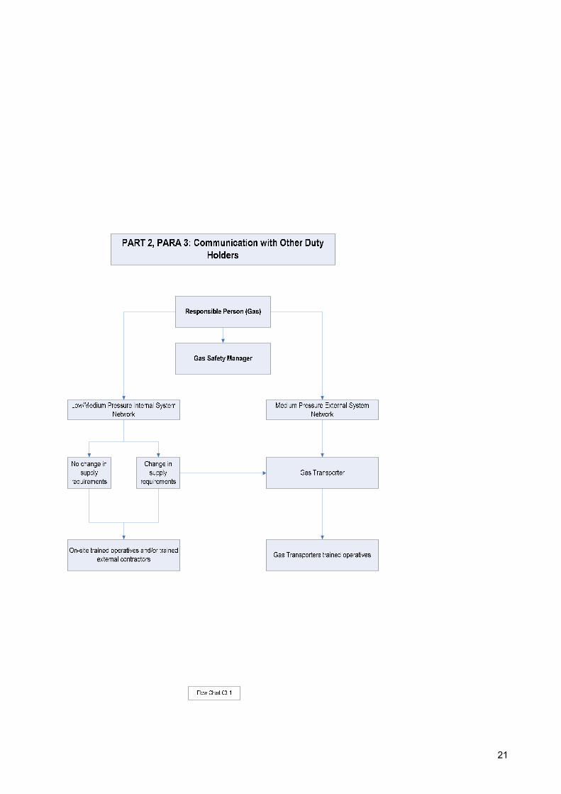
21 Flow Chart 03-1
Communication with other Duty Holders
Gas Network Overview
22 4a Technical Specification
References to other Technical Specifications, which the duty holder intends to use for the safe management of natural gas
Part 3 Page No. Para Heading Paragraph from Schedule 1 of GS(M)R 1996 23 Content Part 3 24 4b Operation &
Maintenance Procedures and arrangements relating to the operation and maintenance of the natural gas network
25 Flow Chart 04B-1
Operation and Maintenance
26 Flow Chart 04B-2
Operating Plan and Equipment Low & Medium Pressure
27 Flow Chart 04B-3
Scheduled and Unscheduled Activities
28 Flow Chart 04B-4
Dealing with long duration shutdowns
Managing Safety
29 Flow Chart 04B-5
Dealing with long duration shutdowns
2
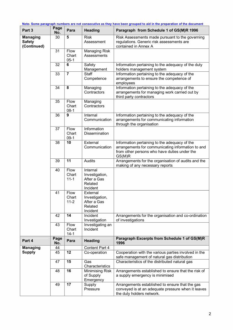
Note- Some paragraph numbers are not consecutive as they have been grouped to aid in the preparation of the document
Part 3 Page No. Para Heading Paragraph from Schedule 1 of GS(M)R 1996 30 5 Risk
Assessment Risk Assessments made pursuant to the governing regulations. Generic risk assessments are contained in Annex A
31 Flow Chart 05-1
Managing Risk Assessments
32 6 Safety Management
Information pertaining to the adequacy of the duty holders management system
33 7 Staff Competence
Information pertaining to the adequacy of the arrangements to ensure the competence of employees
34 8 Managing Contractors
Information pertaining to the adequacy of the arrangements for managing work carried out by third party contractors
35 Flow Chart 08-1
Managing Contractors
36 9 Internal Communication
Information pertaining to the adequacy of the arrangements for communicating information through the organisation
37 Flow Chart 09-1
Information Dissemination
38 10 External Communication
Information pertaining to the adequacy of the arrangements for communicating information to and from other persons who have duties under the GS(M)R
39 11 Audits Arrangements for the organisation of audits and the making of any necessary reports
40 Flow Chart 11-1
Internal Investigation, After a Gas Related Incident
41 Flow Chart 11-2
External Investigation, After a Gas Related Incident
42 14 Incident Investigation
Arrangements for the organisation and co-ordination of investigations
Managing Safety (Continued)
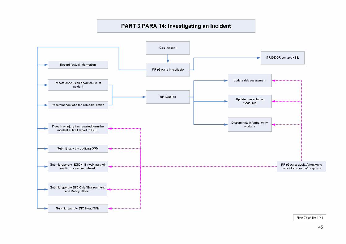
43 Flow Chart 14-1
Investigating an Incident
Part 4 Page No. Para Heading Paragraph Excerpts from Schedule 1 of GS(M)R
1996 44 Content Part 4 45 12 Co-operation Cooperation with the various parties involved in the
safe management of natural gas distribution 47 15 Gas
Characteristics Characteristics of the distributed natural gas
48 16 Minimising Risk of Supply Emergency
Arrangements established to ensure that the risk of a supply emergency is minimised
Managing Supply
49 17 Supply Pressure
Arrangements established to ensure that the gas conveyed is at an adequate pressure when it leaves the duty holders network.

3
Part 5 Page No. Para Heading Paragraph Excerpts from Schedule 1 of GS(M)R 1996 50 Contents Part 5 51 13a Gas Leaks Particulars of the arrangements the duty holder and any
emergency service provider have established to deal with gas leaks
53 Flow Chart 13a-1
Gas Leak Emergency Management (Overview)
54 Flow Chart 13a-2
Incident Notification
55 Flow Chart 13a-3
Initial Response
56 Flow Chart 13a-4
Emergency Services at scene of incident
57 Flow Chart 13a-5
Assessing the level of hazard arising from the gas incident
58 Flow Chart 13a-6
Resolving the gas incident
59 Form 13a-7
Incident report – Gas Distribution System
62 Form 13a-8
Check List for Major Emergencies
63 13b Service Providers
Particulars of the arrangements the duty holder has established to appoint emergency service providers
64 18 Supply Emergency
Particulars of the arrangements for dealing with supply emergencies
65 Flow Chart 18-1
Local Supply Emergency
66 Flow Chart 18-2
Local Supply Emergency
67 19 Non Conforming Gas
Arrangements established for conveying non-conforming gas in the network
68 20 Discontinue Supply
Procedures established to discontinue supply to consumers
69 Flow Chart 20-1
Interrupting Supply to Customers (1)
70 Flow Chart 20-2
Interrupting Supply to Customers (2)
71 21 Re-establish Supply
Procedures established to restore gas supply to consumers
Managing Emergencies
72 Flow Chart 21-1
Upon Resolution of Supply Emergency

4
Annexes Page No.
Annex A 72 Generic Risk Assessments
Generic risk assessments 1 -15
Annexe B 88 Inspections & Investigations by External Authorities
Details of external Authorities who have a statutory right to undertake inspections and investigations in relation to gas incidents
Annexe C DIO and MMO H&S Policy’ Organisation & Arrangements for the Management of Gas Networks
Annexe D Establishment Layout & Schematic Diagram of Gas Distribution Network
Schematic diagrams of individual networks both medium and low pressure clearly identifying location of the interface between EGDN & MOD networks
Annexe E General Description of the MMO Operations
Annexe F Organisation Chart Showing Lines of Communication Between Establishment, DIO & MMO
Annexe G Roles and responsibilities
Organisational hierarchy Roles and duties
Annexe H Competence, training & appointment
Suitability criteria Training requirements GSM refresher training Site/network familiarity Site/network familiarity Assessment
Annexe I Cooperation and communication
Key interfaces Allocation of responsibilities and demarcation agreements Construction works
Annexe J Planning & implementing
Risk assessment Document centre Operational restrictions
Annexe K Assurance

5
Part 1: Introduction
Section 1.2: About this Document INFORMATION Part 1 has been written to give the user a better understanding of how the document is
meant to be navigated. It is divided into the following 7 sections 1.1 Contents
Page Section 1.1 shows the contents of all five parts
1.2 About this Document
Section 1.2 (this section) gives a brief overview of how the document is laid out and the purpose of the document as a whole
1.3 Using the Document
Section 1.3 gives a visual indication of how the document is divided
1.4 Incident Management
Section 1.4 is a quick selection index which allows the user to turn directly to the required heading
1.5 Document Management
Section 1.5 allows the user to establish revision control. This document should be updated after changes to the design, gas incidents, audits & any other works that impact on the distribution of natural gas on site.
1.6 Acronyms Section 1.6 lists the various acronyms used in this document 1.7 Appendices The statutory literature that is connected to this document is enclosed for reference as
are other MOD specifications THE PURPOSE The purposes of this document are as follows 1a To define clear lines of communication, procedures and processes that need to be
implemented in the day to day running of a gas network 1b To define clear lines of communication, procedures and processes that need to be
implemented to reduce the risk of a ‘incident’ involving gas 1c To define clear lines of communication, procedures and processes that need to be
implemented in the eventuality of a ‘incident’ involving gas. 1d The final purpose of this document is to ensure that the site complies with the Gas
Safety (Management) Regulations 1996, and in particular Regulation 3 of the regulations which state the following: To comply with Regulation 3 of the GS(M)R 1996 which states Regulation 3 – Duties on Persons Conveying Gas. “No person shall convey gas in a network unless” – “He has prepared a safety case containing the particulars specified in Schedule 1 of the GS(M)R and that safety case has been accepted by the Executive”
2a
The MOD has prepared a generic gas safety case for all Establishments in the United Kingdom subject to the GS(M)R, which includes bases that are occupied by the United States Visiting Forces. As the MOD is creating a Exemplar Gas Safety Case, each site is to have this follow-up document which points to all site specific documents and procedures required under Schedule 1 of the GS(M)R 1996.
2b
This document should be treated as a ‘living document’ and must be updated and audited on a regular basis.
THE PARTS This document is divided into five parts as shown below: Part
1 Introduction Part 1 introduces this document to a new and returning user. It indicates how the
document should be used and also contains a quick reference to the procedures Part
2 Gas Network Overview
Part 2 contains technical & descriptive information on the gas network
Part 3
Managing Safety
Part 3 describes/refers to the processes and procedures in place that control the gas safety management system on site
Part 4
Managing Supply
Part 4 describes/refers to the processes and procedures in place that control the gas supply management system on site
Part 5
Managing Emergencies
Part 5 describes/refers to the processes and procedures in place that control the gas emergency management system on site

6
PART 5
PART 4: Managing Supply
Co-operation
Particulars of the arrangements the duty holder has established to enable him to comply with regulation 6 (co-operation) including (except where he is the network emergency co-ordinator) particulars of the arrangements
Paragraph 12
Other Parties
General Arrangements
Co-operation with Transco:
The arrangements with customer in the event of a supply emergency are set out in Part 5, Para 18 of this document. Refer to Flow Chart 13a_1
PART 1
PART 2
PART 3
Part 1 is divided into multiple sections to assist in using this document.
Tabs should be used to divide the document into the five main parts.
Additional Tabs are recommended to divide Parts 2 to 5 into the twenty paragraphs set out in Schedule 1 of the GS(M)R 1996
PART 4
Part 1, Section 1.3: USING THE DOCUMENT

7
PART 4: Managing Supply
Co-operation
Particulars of the arrangements the duty holder has established to enable him to comply with regulation 6 (co-operation) including (except where he is the network emergency co-ordinator) particulars of the arrangements
Paragraph 12
Other Parties
General Arrangements
Co-operation with Transco:
The arrangements with customer in the event of a supply emergency are set out in Part 5, Para 18 of this document. Refer to Flow Chart 13a_1
PART 4
PART 5
PAR
A 1
2
Part Heading Paragraph Heading
Paragraph Extract from Schedule 1.
Main Headings from Paragraph
Sub Heading
Part and Paragraph Reference
Reference to Flow Chart. (for example: 13a_1
refers to Flow Chart 1 under paragraph 13a).

8
PART 1, Section 1.4: Incident Management
Managing Gas Supply Emergencies
Managing Gas Emergencies
Emergency and Long Term Shutdowns
Discontinuing Supply
Maintenance in the Event of Failure
Incident Investigation
Reinstating Supply
Audits
Risk Assessment
On-site Gas Operatives
PPM and Safety Inspections
Outside Contractors
Operating Plant and Equipment
Internal Communication
Design Changes
Interruptible Consumer on Site
Technical Details of Network
Details of On-site Responsible Parties
Meter Readings
Drawings
Technical Specifications (for the safe management of gas)
Part 5: Paragraph 18
Part 5: Paragraph 13a
Part 5: Paragraph 4b
Part 5: Paragraph 20
Part 3: Paragraph 4b
Part 3: Paragraph 14
Part 5: Paragraph 21
Part 3: Paragraph 05
Part 3: Paragraph 11
Part 3: Paragraph 07
Part 3: Paragraph 4b
Part 3: Paragraph 08
Part 3: Paragraph 4b
Part 3: Paragraph 09
Part 3: Paragraph 4b
Part 2: Paragraph 02
Part 2: Paragraph 02
Part 2: Paragraph 01
Part 2: Paragraph 03
Part 2: Paragraph 03
Part 2: Paragraph 4a

9
Part 1: Introduction
Section 1.5: Document Management VERSION ISSUE
DETAIL DESCRIPTION WORK
BY: APPROVED BY:
REVIEW DATE
Version 1.0 Alconbury GSMP
Original version produced for RAF Alconbury by DE Ops Int (USF)
Version 1.02 Draft of amended GSMP
Issued to DE Operations Directorates and RPC for consultation
Version 2.0 Issued to external Gas Specialists for Review
Version 5.0
Major update to reflect changes to management structure within DIO. Removal of references to JSP 375 vol 3.
RAC RAC June 13
Annexe G Roles and responsibilities
Annexe H Competence, training & appointment
Annexe I Cooperation and communication
Annexe J Planning & implementing
Annexe K Assurance
This document was created by ……………………………………………….. for the MOD.
The parts of this document that deal with the safe management of the flow of gas and the provision of an emergency response service must be audited periodically. In particular audits are to be conducted a minimum of six months after gas emergencies & incidents. Audits should also be carried out after significant changes to management arrangements and/or the natural gas distribution system. (GS(M)R 1996, Schedule 1, Paragraph 11).

10
Part 1: Introduction
Section 1.6: Acronyms DIO Defence Infrastructure Organisation DHW Domestic Hot Water DIN Defence Instruction Notice E&C Engineering & Construction ES Emergency Services GSM Gas Safety Manager ( formerly Authorised Engineer –Mechanical) GS(M)R 1996 Gas Safety (Management) Regulations 1996 GSMP Gas Safety Management Plan (This Document) H&S Health and Safety HSE Health and Safety Executive LPG Liquid Petroleum Gas MOD Ministry of Defence NEC Network Emergency Co-ordinator NG Natural Gas NGG National Grid Gas plc Emergency Co-ordinator ODC Operation Delivery & Coherence PPM Planned Preventative maintenance RA Risk Assessment RIDDOR Reporting of Injuries, Diseases and Dangerous Occurrences and Regulations 1995 RP(Gas) Responsible Person - Gas SIM Senior Infrastructure Manager SN Site Name

11
Part 1: Introduction
Section 1.7: Reference Documents SI 1996 No 551 Gas Safety (Management) Regulations 1996 SI 1998 No 2451 Gas Safety (Installation and Use) Regulations 1998 L80 A Guild to the Gas Safety (Management) Regulations 1996 – HSE Guidance on
Regulations – Contains details of what is contained in Schedule 1 of the GS(M)R 1996 Regs
L56 Approved Code of Practice – Safety in the installation and use of gas systems and appliances
HSE GS(M)R Safety Case Assessment Manual
Gas Safety (Management) Regulations 1996, Safety Case Assessment Manual – This guide is used by safety case assessors, and as such is a useful document to use as reference in creating a gas safety management plan.
HSE Enforcement Policy for the replacement of iron gas mains 2006 – 2013 – December 2005 http://www.hse.gov.uk/gas/supply/mainsreplacement/irongasmain.htm
HSE A Guide to regulation 13A of the Pipeline Safety Regulations 1996 HSE Gas supply – Monitoring and reporting of Distribution Networks.
http://www.hse.gov.uk/gas/supply/mainsreplacement/monitoring.htm IGE/GL/9 IGEM Gas Legislation Guidance – Guidance for large gas consumers in dealing with
Natural Gas supply emergencies

12
Part 1: Introduction
Section 1.8: Glossary. Natural Gas Low Pressure Less than 75 mbar Medium Pressure Up to 2 bar Intermediate Pressure
Not exceeding 7bar
Safety Case A document detailing the organisation and arrangements an organisation has in place for undertaking the role as a Public Gas Transporter. The Safety Case containing the particulars required by Schedule 1 of the Gas Safety (Management) Regulations which has to be formally accepted by the Health and Safety Executive
LPG High Pressure 6.8 bar @15O C (Bulk tank) Medium Pressure 75 mbar Standard Operating pressure
37mbar (Supply pipe to building)
Incident Commander
Person in charge of the incident
External Gas Distribution Networks
External Gas Distribution Networks (EGDN) in place at the time of publication of this document (see following page)

13
LDZs North West, North London, West Midlands, East Midlands, East Anglia, Scotland, South, South East, Wales, South West, North and Yorkshire EGDNs North West, North London, West Midlands and East of England are owned and managed by National Grid Gas plc (the area outlined in black) Scotland & South of England are owned and managed by Scotia Gas Networks – operating as Scotland Gas Networks Ltd and Southern Gas Networks Ltd respectively Wales and the West is owned and managed by Wales and West Utilities North of England is owned and operated by Northern Gas Networks Ltd
www.nationalgrid.com/uk/Gas/About/How+Gas+is+Delivered/ National Grid Gas plc also operate the National Transmission System (NTS)

14
Part 2: Gas Network Overview Contents of Part 2: Gas Network Overview
Part Para Heading Paragraph Excerpts from Schedule 1 of GS(M)R 1996 1 The Duty
Holder Name and address of the person preparing the safety case (in this Schedule referred to as the “Duty Holder”).
2 The Operation
A description of the operation intended to be undertaken by the duty holder.
3 General Descriptions
A general description of the plant and premises the duty holder intends to use in connection with the operation including, in particular, the geographical location where any pipes he uses join pipes used by other persons for conveying gas.
2 Gas Network Overview
4a Technical Specification
Particulars of any Technical Specifications, which the duty holder intends to follow in connection with the operation he intends to undertake insofar as they affect the health and safety of persons.
Introduction to Part 2: Gas Network Overview About Part 2: This section highlights the following:
Persons responsible for the safe flow of gas on site & their contact details. An overview of the gas network onsite.
Technical details of the gas network (pipe sizes, lengths and operating pressures).

15
Part 2: Gas Network Overview
Paragraph 1: The Duty Holder Paragraph 1 Name and address of the person preparing the safety case (in this Schedule
referred to as the “Duty Holder”). Duty Holder
Defence Infrastructure Organisation
Duty Holders Address
Kingston Road Sutton Coldfield B75 7RL Tel: 0121 311 3228 Fax 0121 311 3809
Duty Holder Contact
Robin Cawthorne
Duty Holder Contact Address (If different from above)
As Above Tel: Fax:
Site Responsibility
Contact details of Head of Establishment
Site Contact Address
Responsible Person Gas Tel: Fax:

16
Part 2: Gas Network Overview
Paragraph 2: The Operation Paragraph 2 A description of the operation intended to be undertaken by the duty holder. Overview The site comprises of ……………………………….. There are approximately …….
People stationed on this establishment. The Purpose of the Pipeline(s)
Pipe Line Detail The table below shows approximate total pipeline lengths for the different pipe diameters, the volume of gas currently flowing through the pipes, the capacity constraints and the associated operating pressures.
Pressure (bar) Dia (mm)
Pipe Types Total Length
(m)
Volume (m³/hr)
Capacity Constrains
(m³/hr) The volume of gas likely to be conveyed should be determined from a site specific network analysis. The EGDN should be able to identify the supply capacity constraints as this will normally be the EGDN metering capacity to the site. Supply pressure from the EGDN could vary between medium (up to 2 bar), intermediate (2 bar to 7 bar) or high pressure (above 7 bar). Interruptible Consumers
Site Name as a site is/is not an interruptible consumer and as such their gas supply can/cannot be terminated in the event of a gas emergency.
In the event of a gas emergency the various premises on the base may have their gas supply temporarily suspended. The procedure associated can be found in Part 5, Para 18. The list of consumers over-sheet must be used in conjunction with these procedures.
Operational Characteristics
MOD (Defence Infrastructure Organisation), being the Duty Holder for the site, control the safe management of natural gas distribution on this base. Refer to the Flow Chart 2-1.
The maintenance of the external medium pressure gas line falls to the local gas transporter, (enter name of EGDN).
The maintenance of the internal medium/low pressure gas line falls to the site maintenance team.
Adjoining networks The mains supply (medium pressure pipeline) from which the site receives its gas is shown on drawing no……………….

17
Part 2: Gas Network Overview
Paragraph 2: The Operation (Interruptible consumers). Building
Ref Building Type Gas Usage / Heating Plant Safety
Critical Contingency

18
PART 2, PARA 2: Organisational Hierarchy for the Safe Management of Gas
DUTY HOLDER MOD
GAS SAFETY MANAGER
RESPONSIBLE PERSON GAS
TRAINED GAS MAINTENANCE CONTRACTORS
TRAINED IN-HOUSE GAS MAINTENANCE OPERATOR
TRAINED EGDN OPERATOR
Flow Chart No 02-1

19
Part 2: Gas Network Overview
Paragraph 3: General Descriptions Paragraph 3 A general description of the plant and premises the duty holder intends to use
in connection with the operation including, in particular, the geographical location where any pipes he uses join pipes used by other persons for conveying gas.
Archive Drawings
e.g. Original drawings of the gas network can be found in the MMO office (Contact RP(Gas)). These drawings are not to scale.
Archive Drawing 1
Archive Drawing 2
Archive Drawing 3
Archive Drawing 4
Drawings Prepared for this document
The drawings shown below (and appended to the end of this paragraph) are re-worked / scaled versions of the archived drawings shown above. Copies of these drawings are to be held in this file, and electronically with this document.
Gas layout drawing 1
Gas layout drawing 2 Gas layout drawing 3
Gas layout drawing 4
Continue with layout drawings as appropriate.
Drawing Content The above drawings indicate the following Geographical location of pipes
Refer to the appended drawings to view the installed pipeline network & all associated control equipment
Refer to the appended drawings to view the incoming gas supply and outgoing decommissioned pipeline. Also shown is the geographic boundary of the site.
Safety Critical Plant The installed safety critical plant and other control equipment are shown on the above drawings.
Control Centres There are no control centres on site which are the responsibility of the RP (Gas), however there is a medium pressure control centre located in the middle of the site which is the responsibility of the gas transporter (insert name of EGDN). This can be seen on Drawings xxxxxxx
Interfaces As shown in Paragraph 2 (General Description) of this document The main supply medium pressure pipeline from which site receives its supply runs The duty holder for the incoming pipeline is (enter name of EGDN) Other General Details
The sections below highlight other details that are set out in Schedule 1
Communication with other duty holders
Site Name has only one duty holder connected to its gas network. This duty holder is (enter name of EGDN) who is the gas transporter. Communication for all work on both the Medium and Low Pressure networks should be as per Flow Chart03_1.
Network Emergency Co-ordinator
The Network Emergency Co-ordinator is (enter name of EGDN)
Design Changes Refer to Part 3, Flow Chart 04b_5 for the procedures and processes that control any changes to the design of the gas network.
Gas Consumption The consumption of gas must be monitored and recorded where possible. It is the CO/HoE responsibility to analyse gas consumption patterns. The table below is to be used to record quarterly and yearly meter readings. This is to be kept updated by the CO/HOE Current running volumes and consumption constraints can be found in Part 2, Paragraph 2 (General Description).
Supply pressure from the EGDN could vary between medium (up to 2 bar), intermediate (2 bar to 7 bar) or high pressure (above 7 bar).
The following sheet detail quarterly gas consumption for the site. This section is to be filled in by the CO/HoE every Quarter.
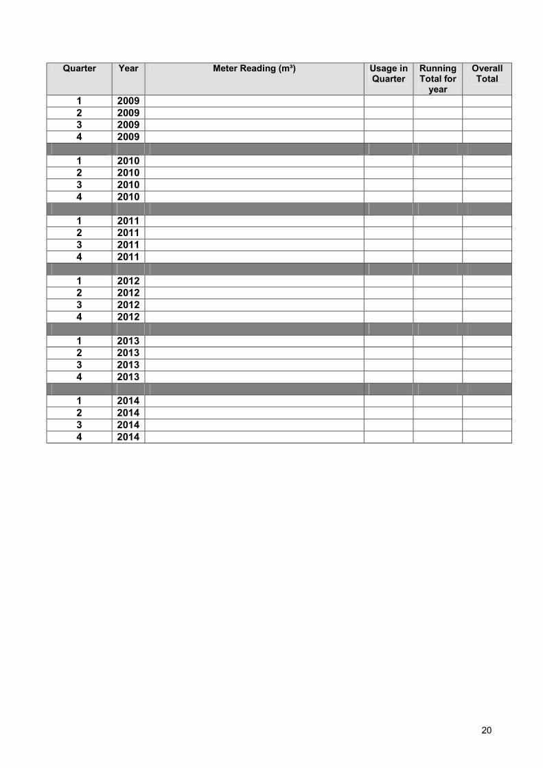
20
Quarter Year Meter Reading (m³) Usage in
Quarter Running Total for
year
Overall Total
1 2009 2 2009 3 2009 4 2009
1 2010 2 2010 3 2010 4 2010
1 2011 2 2011 3 2011 4 2011
1 2012 2 2012 3 2012 4 2012
1 2013 2 2013 3 2013 4 2013
1 2014 2 2014 3 2014 4 2014
21

22
Part 2: Gas Network Overview
Paragraph 4a: Technical Specifications Paragraph 4a Particulars of any – (a) Technical Specifications Technical Specifications
Gas Safety Management Plan (GSMP) – This document highlights the roles and responsibilities of natural gas distribution on MOD sites. It contains references to risk assessments emergency plans & other documents vital to maintaining the safe flow of gas.
IGE/GL/7 - Communication 1632 - Gas Legislation Guidance for Safety Cases.
IGE/G/1 - Communication 1703 – Defining the End of the Network, a Meter Installation and Installation Pipework.
IIGE/TD/10 - Institution of Gas Engineers Recommendations on Transmission and Distribution Practice - Pressure Regulating Installations for Inlet Pressures between 75 mbar and 7 bar. 1976 & 1986.
IGE/GM/8 - Non-Domestic Meter Installations. Flow rate exceeding 6 m3h-1 and Inlet Pressure Not Exceeding 38 bar. Parts 1 to 5.
IGE/TD/3: Edition 4:2003 - Communication 1677 - Steel and PE Pipelines for Gas Distribution.
IGE/TD/4: Edition 3:1994 - Communication 1562 - Gas Services.

23
Part 3: Managing Safety
Contents of Part 3: Operation & Maintenance. Part Para Heading Paragraph Excerpts from Schedule 1 of GS(M)R 1996
4b Operation & Maintenance
Particulars of any procedures or arrangements relating to operation and maintenance, which the duty holder intends to follow in connection with the operation he intends to undertake insofar as they affect the health and safety of persons.
5 Risk Assessment
A statement of the significant findings of the risk assessment have made pursuant to Regulation 3 of the ‘Management of health and safety at Work Regulations’ , and particulars of the arrangements he has made in accordance with regulation 3 thereof.
6 Adequate Safety Management
Particulars to demonstrate that the management system of the duty holder is adequate to ensure that the relevant statutory provisions will be (in respect of matters within his control) complied with in relation to the operation he intends to undertake.
7 Staff Competence
Particulars to demonstrate that the duty holder has established adequate arrangements for ensuring the competence of his employees in health and safety matters.
8 Managing Contractors
Particular to demonstrate that the duty holder has established adequate arrangements for managing work carried out by persons who are not his employees on or in relation to plant or premises which he owns or controls.
9 Internal Communication
Particulars to demonstrate that the duty holder has established adequate arrangements for passing information relevant to health and safety to persons within his undertaking.
10 External Communication
Particulars to demonstrate that the duty holder has established adequate arrangements for passing and receiving information relevant to health and safety to and from other persons who have duties under these regulations.
11 Audits Particulars to demonstrate that the duty holder has established adequate arrangements for audit and the making of any necessary reports.
3 M
anag
ing
Safe
ty
14 Incident Investigation
Particulars to demonstrate that the duty holder has established adequate arrangements to enable him to comply with Regulation 7(12), (13), (15) & (16) of the GS(M) Regs, for co-ordinating the investigations he causes to be carried out pursuant to that regulation with other investigations carried out pursuant thereto, and for participating in such other investigations.
Introduction to Part 3: Managing Safety About Part 3: This section highlights
The procedures, processes in place to control the safe flow of natural gas at Site
Name. The roles and responsibilities of those who manage or undertake work on the gas
system.

24
Part 3: Managing Safety
Paragraph 4b: Operation and Maintenance. Paragraph 4b Particulars of any – (b) Procedures or arrangements relating to operation and
maintenance; Which the duty holder intends to follow in connection with the operation he intends to undertake insofar as they affect the health and safety of persons.
Safe Management of the flow of gas
This paragraph puts into place the procedures and processes required under Schedule 1 with regards to the management structure needed to safely control the flow of gas in a network. Further information can be found in Annex G of this document
The various incidents/events that are shown below are further detailed in various Flow Charts. Refer to Flow Chart 04b_1 over-sheet for more information.
Operating Plant & Equipment
The RP (Gas), has the services of insert number Gas Safe Registered operatives on site. These individuals run the day to day operation of the plant and associated equipment. (Ref: Flow Chart 04b_2).
Scheduled PPM & Safety Inspections
The RP (Gas) will liaise with Customer Services & (enter name of EGDN) to carry out planned works that may interrupt the flow of gas. (Ref: Flow Chart 04b_3)
Plant failure There are insert number Gas Safe Registered operatives who are trained on domestic and insert number competent persons for work on distribution mains and services and who hold appropriate gas industry recognised qualifications such as Gas Distribution (GD) or Gas Network Operations (GNO) certificates. Normally the external contractors employed by MOD MMO. If external medium pressure work is essential, (enter name of EGDN) is contacted. MMO Customer services will inform the interruptible consumers of supply failures. (Ref: Flow Chart 04b_3). Personnel working on the MOD gas distribution networks should be registered under the Energy & Utility Skills Register (EUSR), this will ensure that qualifications and competence are appropriate to the work being undertaken. EUSR operates an independent skills register which provides recognised standards for the utilities sector see; http://www.eusr.co.uk/ This is in addition to Gas Safe registered operatives who are qualified to work downstream of the customer Emergency Control valve.
Emergency Shutdowns
The RP (Gas) will inform customer services & (enter name of EGDN) in the event of an emergency shutdown. (Ref: Flow Chart 04b_3).
Long Duration Shutdowns
In the event of a long duration shutdown, high risk buildings can be provided with temporary heaters (houses with very young infants, infirmaries etc). The option to switch the heating plant to a different fuel type is also available. The decision regarding the switch can only be made by the CO/HoE. (Ref: Flow Chart 04b_4).
Dealing with other Gas transporters
The gas transporter(s) connected to this site is (enter name(s) of EGDN). Refer to Part 2, Para 3, Diagram 03_1.
Gas Leaks Management of gas leaks is dealt with in Part 5. (refer to Part 5: Para 13a). Design Changes
Changes to the gas distribution network should only be made by qualified Gas Distribution (GD) or Gas Network Operations (GNO) operatives. A Network Analysis review should also be undertaken as part of any network design changes, this will ensure correct pipe sizes and also that adequate pressures are maintained in the gas network. For changes to the medium pressure gas network must be instructed through the RP (Gas) as per Flow Chart 04b_5. Changes to the external medium pressure network can only be made by the (enter name of EGDN) as the Gas transporter will inform personnel on site of any design changes and it is the responsibility of the RP (Gas) to ensure that any changes are incorporated in the site drawings. All drawings must be updated along with the relevant O&Ms and Documentation. Any changes made to the low/medium pressure gas network onsite must be instructed through the RP (Gas) as per Flow Chart 04b_5. Changes to the gas network can only be made by qualified Gas Safe Registered operatives. The gas transporter does not need to be informed of any minor changes to the system. However if the requirement for gas supply is significantly increased the gas transporter must be informed. It is the responsibility of the RP (Gas) to notify the gas transporter of any change in supply demand. It is the responsibility of the RP (Gas) to ensure that any changes are incorporated in the site drawings. All drawings

25
must be updated along with the relevant O&Ms and documentation. Liaising with Emergency Services
Part 5: Managing Emergencies, deals with the role played by the emergency services.
Training of Staff
Refer to Part 3: Paragraph 7 for details on training and assessing competence levels.
Audits
Refer to Part 3: Paragraph 11 for details on Audits.
Cast & ductile iron pipe
Where any cast or ductile iron pipework is identified it is to be recorded and entered into a mains replacement programme developed to meet the objectives of the HSE enforcement policy: see; http://www.hse.gov.uk/gas/supply/mainsreplacement/ irongasmain.htm

26
PART 3 (PARA 4b): Managing Safety – Operation Maintenance
Operating Plant and Equipment – Low and Medium Pressure (04b 2)
Scheduled PPM and Safety Inspections (04 3)
Maintenance in the event of plant failure (04 3)
Emergency shutdowns (04 3)
Long term shutdowns (04 4)
Dealing with other Gas Conveyors (03 1)
Gas leaks – Low / Medium Pressure (13a 1)
Managing design changes to the gas network (04 5)
Liaising with Emergency Authorities (03 1)
Training staff (Para 07)
Audits (Para 11)
Risk Assessments (05 1)
Managing Contractors (08 1)
Gas incident investigation (14 1)
Procedures and Processes for the Management of the safe flow of gas through the network
Flow Chart No. 04b-1

27
PART 3, PARA 4b: Operating Plant and Equipment –Low & Medium Pressure
Day to day operation of associated plant and
equipment at low pressure
Planned maintenance of low pressure system
Customer reported problem (Low Pressure System)
RP (Gas) co-ordinates
Gas Safe Registered, Gas Distribution, or Gas Network Operations
competent persons on-site operatives / outside
contractors
EGDNoperatives and procedures
Network Co-ordinator
Day to day operation of associated plant and
equipment at medium pressure
Customer reported problem (Medium Pressure System)
Planned maintenance of medium pressure system
Flow Chart No 04b-2

28

29
PART 3, PARA 4b: Dealing with long duration shutdowns
RP (Gas) informs the CO/HoE of potential long duration shutdown period
CO/HoE decideNot to switch to dual fuel
Customer Services to inform areas affected by shutdown
Customer Services to provide families with young children / Infirmaries / areas that require heating with temporary heaters, until
service is restored
Switch to dual fuel(if available)
RP (Gas) to facilitate the switching of the heating plant
Flow Chart No 04b-4

30

31
Part 3: Managing Safety
Paragraph 5: Risk Assessment. Paragraph 5 A statement of the significant findings of the risk assessment he has made
pursuant to regulation 3 of the ‘Management of health and safety at Work Regulations’ 1992 (SI 1992/2051), and particulars of the arrangements he has made in accordance with regulation 4 thereof.
Risk Assessments
The generic risk assessments in Annex A, highlight the factors that will affect the safe management of the flow of gas, and the provision of the emergency response service.
Required RA’s As per the incident management section of this document, the following risk
assessments analyse the hazards associated with the following: 1 Any gas leak considered hazardous to persons or property (Under med/low pressure
conditions). 2 Fire or explosion near to, or directly involving, a pipeline or gas facility. 3 A failure of operation of pipeline/plant onsite, or immediately downstream of site, that is
maintained by the gas transporter ((enter name of EGDN)). 4 A failure of operation of pipeline/plant onsite that is maintained by site services. 5 Failure of safety critical equipment. 6 Under-pressure in the gas system. 7 Over-pressure in the gas system. 8 Failure in system during load shedding. 9 General changes to the gas network.
10 Failure of PPM, general operation of the gas network plant/equipment and safety inspections.
11 Emergency Shutdowns. 12 Interface with Gas Transporter. 13 Interface with the Customer. 14 Interface with Emergency Services. 15 Natural Disasters, civil disturbances, other unforeseen events. 16 Production of Carbon Monoxide from incomplete burning of gas 17 Faulty Appliances
General Risk Assessment
The RA’s in Annex A are overview RA’s and identify what hazards can be expected. These should also show preventative measures in place. The RA in Annex A are generic and must be made job specific before they can be used for undertaking work activities. Any identified site specific risks to the safe management of the flow of gas or the provision of an effective emergency response should be added at Annex A to this GSMP
Work Specific Risk
Assessments
Before any works which involve the gas network are started, the parties involved must present a RA to the RP (Gas) for approval. The RP (Gas) must check the RA against the General RAs in Annex A to ensure that all hazards are identified before approving any works or issuing any permits.
Communicating with other parties
It is the RP (Gas) responsibility to request an RA from the party intending to do the work.
Re-assessment Currently any permits must pass/gain several signatures, from the various heads of departments, before work is authorised.
According to Regulation 4(3) the above RA’s should be re-evaluated every three years, as part of the general review of this document.
The re-assessment allows any previously unidentified risks, or new risks to be identified and preventative measures to be put into place.
Re-assessment must also be carried out after any gas related incident. For more information on how risks are managed Refer to Flow Chart 05_1.

32

33
Part 3: Managing Safety Paragraph 6: Adequate Safety Management.
Paragraph 6 Particulars to demonstrate that the management system of the duty holder is adequate to ensure that the relevant statutory provisions will (in respect of matters within his control) be complied with in relation to the operation he intends to undertake Under this paragraph of Schedule 1, the duty holder has a responsibility to demonstrate that the management system is capable of controlling safely the flow of gas
Management System
This document is the primary reference onsite that demonstrates due diligence Under this paragraph of Schedule 1, the duty holder must make a provision to monitor the progress of H&S arrangements onsite
Monitoring H&S Performance
Part 3 in this document is the primary reference onsite that demonstrates due diligence
Internal monitoring
Refer to Part 3, Para 11: Audits. Recording and Reporting
Refer to Part 3, Para 11 & Part 3, Para 14

34
Part 3: Managing Safety Paragraph 7: Staff Competence.
Paragraph 7 Particulars to demonstrate that the duty holder has established adequate arrangements for ensuring the competence of his employees in health and safety matters. The Gas Safety Manager Oversees multiple sites. TheGSM will have the appropriate qualifications and experience as defined in Annex G The Responsible Person (RP) (Gas): Co-ordinates the maintenance and repair of the site’s natural gas network. Monitors the operatives on site including contractors, ensuring they are fully trained and competent. Ensures that the risk assessments are up to date and that the procedures are followed. The RP (Gas) will have the appropriate qualifications and experience as defined in Annex G The Operatives: All operatives will be Gas Safe Registered, in both Domestic and Commercial installation and are able to work on the low pressure network both internal and external. There is also a requirement to have access via the MMO to trained personnel who are qualified to work on gas distribution mains and services and hold appropriate gas industry recognised qualifications such as Gas Distribution (GD) or Gas Network Operations (GNO) certificates. Personnel working on the MOD gas distribution networks should be registered under the Energy & Utility Skills Register (EUSR), this will ensure that qualifications and competence are appropriate to the work being undertaken. EUSR operates an independent skills register which provides recognised standards for the utilities sector see; http://www.eusr.co.uk/. This is in addition to Gas Safe registered operatives who are qualified to work downstream of the customer Emergency Control valve. Customer Services: MMO staff used to handle incident related communications. Contractors: That are brought onto site, must prove competence with the relevant certification. This is covered under Part 3, Para 8. Emergency Services (Internal): The onsite emergency services are controlled by the CO/HoE and as such all training and equipment is provided by the CO/HoE.
Personnel
Emergency Services (External): The local Police, Fire and Ambulance Services It is the responsibility of the RP(Gas) to undertake such checks as is necessary prior to work commencing on the low/medium pressure systems that the onsite personnel & contractors are trained/certified to appropriate industry standards. The operatives must retake their Gas Safe Registration in accordance with the requirements laid down by Gas Safe Register. Records of the training undertaken can be found in the Training File kept with the Responsible Person (RP) (Gas).
Assessing Competence
The staff used to answer gas incident calls and dispatch a response team are insert details, and as such the training and competence assessment is set out in insert details training manuals. The specifications that sets out the required actions and standards for training staff can be found in the following,
GSMs Instructions to RESPONSIBLE PERSON (GAS) All RPs (Gas) are to ensure the following actions are instigated to ensure an
acceptable level of management and control is maintained on gas distribution systems applicable MOD sites:
A Provide and maintain detailed records for inclusion in the RP (Gas) Register of all NG and LPG storage and distribution systems.
B Maintain up to date records of companies and personnel working on the Gas storage and distribution systems on site.
C Ensure those companies used on site operate a safe system of work to comply with statutory requirements.
D Carry out an assessment on individuals training and competency prior to carrying out work.

35
E Set up points of demarcation for both NG and LPG systems. F Ensure requirements of the HSE approved Safety Case for NG systems that
fall within the Gas Safety (Management) Regulations (GSMR)1996 are up to date and in accordance with schedule 1 of the GS(M)R and held in the RP (Gas) Register.

36
Part 3: Managing Safety
. Paragraph 8: Managing Contractors Paragraph 8 Particular to demonstrate that the duty holder has established adequate
arrangements for managing work carried out by persons who are not his employees on or in relation to plant or premises which he owns or controls
Service Families Accommodation (SFA) Housing Outside Contractors
The SFA housing gas systems are maintained through the MMO customer services who can call upon the site maintenance department or, if required an outside contractor.
External Medium Pressure Outside Contractors
(enter name of EGDN) are contacted regarding any works to the external medium pressure network. Refer to Flow Chart 08_1 for documentation that the Responsible Person (RP) (Gas) must check before allowing any works to proceed. (Note The external EGDN network supplying the site could be high pressure (HP), intermediate pressure (IP) or medium pressure (MP))
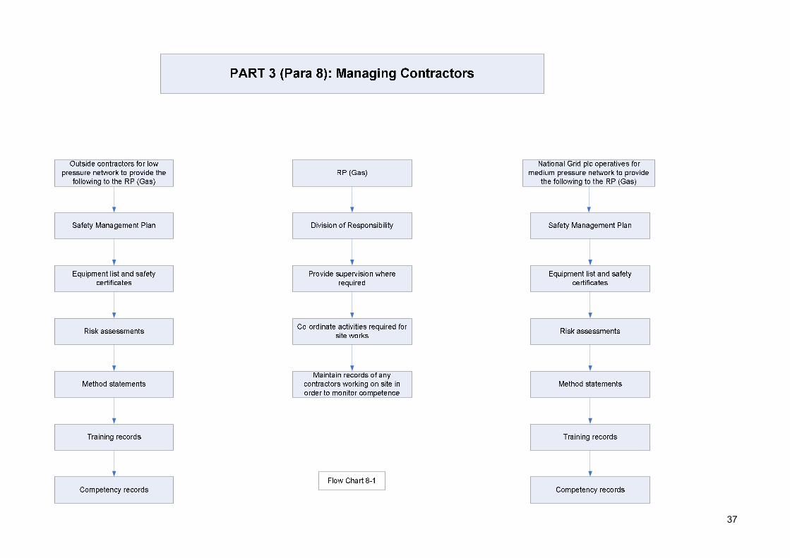
Responsible Person (Gas) Duties for managing outside contractors
The RP (Gas) must ensure that any contractors working on the network have the following arrangements in place. The RP (Gas) must keep records of the following and as set out in Flow Chart 08_1
Management System
The contractors have a management system in place which is consistent with the site management plan and meets safety objectives
Responsibility The division of responsibility must be highlighted by the RP (Gas) for specific aspects of safety management
Safe System of Work
Contractors to follow safe systems of work, including the use of suitable plant and equipment
Training The contractor has enough staff with suitable training and competence.
Supervision Ensure the contractor provides adequate supervision to be supplied where necessary
Monitoring Competence
Maintain records of any contractors working on site in order to monitor their performance and standards
Other Documentation
Risk assessments, permits to work & method statements are required, and fall under the procedures as set out in Part 3, Para 5
37

38
Part 3: Managing Safety
Paragraph 9: Internal Communication Paragraph 9 Particulars to demonstrate that the duty holder has established adequate
arrangements for passing information relevant to health and safety to persons within his undertaking.
There are several systems in place for the successful distribution of information down the chain of command
Insert details of any site wide tannoy system
Insert details of any internal email to inform consumers
Insert details of any direct contact by MOD & MMO employees on a door to door basis
These are shown in Flow Chart 9_1 over sheet
Insert details of any site wide emergency plans and arrangements
Arrangements for the provision of information for dealing with gas escapes from the network can be found in Part 3 Paragraph 14 of this document

39
Res
pons
ible
Per
son
(Gas
)
Gas
Saf
ety
Man
ager
DIO
(MO
D)
Nat
iona
l Co-
ordi
nato
rs
Inst
ruct
ions
Site
Net
wor
k In
stru
ctio
ns

40
Part 3: Managing Safety Paragraph 10: External Communication.
Paragraph 10 Particulars to demonstrate that the duty holder has established adequate arrangements for passing and receiving information relevant to health and safety to and from other persons who have duties under these regulations. (enter name of EGDN) is the only other duty holder connected to the Site Name Network. Information passes between the RP (Gas) and the Network Emergency Co-ordinator at (enter name of EGDN).
Communication with Other Duty Holders
Clear communication between the RP (Gas) and the Network Emergency Co-ordinator at (enter name of EGDN) is required. Including a process through which information can be passed. This includes RAs, preventative measures & lessons learnt. This is demonstrated throughout Part 3 & Part 5.
Communication with Others
Refer to Parts 5 of this document to see arrangements with consumers and the procedure in the event of a leak or a supply failure.

41
Part 3: Managing Safety
Paragraph 11: Audits. Paragraph 11 Particulars to demonstrate that the duty holder has established adequate
arrangements for audit and the making of any necessary reports. Internal Audits the GSM will conduct internal audits of the management system, paying close attention
to the implementation of procedures and processes set out Flow Chart 11_1. See Annex G for details
External Audits Capita Gas Registration and Ancillary Services Limited (Gas Safe Register) currently review management strategies and how the gas service is being managed. However this audit is not a regular scheduled activity. EUSR for gas safety standards for gas distribution networks. Independent audits by competent individuals must be carried out on a regular basis, especially after a change to the organisation. Refer to Flow Chart 11_2. The performance standards for audit and reviews must be set by the GSM.
Audit Standards The latest gas safety standards as set by Gas Safe Register. Gas safety standards set out by EUSR for gas distribution networks.
What should be Audited
• Management system dealing with the safe management of the flow of gas • Management system dealing with the emergency response service. • Audits of the internal auditors will be carried out by Defence Infrastructure
Organisation ODC E&C SME Gas. •
Feedback The results of the Audit should feedback so that corrective action plans are developed.

42

43

44
Part 3: Managing Safety Paragraph 14: Incident Investigation.
Paragraph 14
Particulars to demonstrate that the duty holder has established adequate arrangements to enable him to comply with paragraphs (12, 13, 15 & 16) of regulation 7, for co-ordinating the investigations he causes to be carried out pursuant to that regulation with other investigations carried out pursuant thereto, and for participating in such other investigations.
What is a Incident An incident, in the context of natural gas, is one that poses harm to persons or premises on any scale. For example a gas leak is classed as a incident as is a supply failure.
Dealing with a Incident
Refer to Flow Chart 14_1 for guidance.
Authorised Investigators
• In the event of an explosion the emergency services will conduct an investigation. (The procedures governing the emergency services investigation do not form part of the gas safety management plan).
• (enter name of EGDN) has the authority to conduct an investigation in to the cause of a gas incident.
• The GSM, will investigate any incident on site, and ensure that all preventative measures were undertaken, and all rules and procedures followed. The GSM will take any lessons learnt and pass them to the RP (Gas) to update the gas safety plan. Refer to Flow Chart 14_1.
• Competent person/organisation appointed by MOD to conduct a forensic investigation following a gas incident
See Annex B for details of other external authorise with the powers to undertake investigations in relation to Gas incidents
Incident Location • The Investigating GSM must look into incidents resulting in fires & explosions as a result of escaping gas, downstream of the emergency control.
• The Investigating GSM must look into incidents upstream of the emergency control valve which have, or could have, resulted in a fire or explosion.
Investigations
The investigating officer should: • Record factual information. • Record Conclusions & Recommendations. • Submit report to HSE under regulations contained within RIDDOR, if there are
injuries or deaths resulting from a gas incident. • Submit report to (enter name of EGDN) if medium pressure line was involved.
Competence The Investigating GSM, must have sufficient & relevant training to conduct the investigation, records of these must be submitted with any report produced.
Co-operation Any incidents that the Investigator deems critical AND those that have an impact on the Gas Supplier (CO emission related incidents) should be notified to the Gas Supplier as well as the HSE. Once the investigating officer has recorded, investigated and submitted the conclusions and recommendations, the information should be forwarded to the RP (Gas) to ensure that the recommendations are carried out and any remedial action is taken. Refer to Flow Chart 14_1. The RP (Gas) must update the gas safety plan according to the findings and disseminated the new information throughout the organisation.
Lessons Learnt
The whole process, from investigation (by GSM) through to remedial action (by RP (Gas)) must be audited. Refer to Flow Chart 14_1.
45

46
Part 4: Managing Supply
Contents of Part 4: Managing Supply. Part 4 Para Heading Paragraph Excerpts from Schedule 1 of GS(M)R 1996
12 Co-operation
Particulars of the arrangements the duty holder has established to enable him to comply with regulation 6 (co-operation) including (except where he is the network emergency co-ordinator) particulars of the arrangements he has established to ensure that any directions given to him by the network emergency co-ordinator are followed. Supply pressure from the EGDN could vary between medium (up to 2 bar), intermediate (2 bar to 7 bar) or high pressure (above 7 bar).
15 Gas Characteri-stics
Particulars to demonstrate that the other duty holder has established adequate arrangements to ensure that all gas he conveys complies with regulation 8. The composition of the gas entering the MOD networks is identical to that supplied from the EGDN network. This gas is therefore subject to EGDN Policy and Systems and MOD relies on the fact that gas transported in the EGDN network is already compliant.
16 Minimising Risk of Supply Emergency.
Particulars to demonstrate that the duty holder has established adequate arrangements to minimise the risk of a supply emergency M
anag
ing
Supp
ly
17 Supply Pressure
Particulars to demonstrate that the duty holder has established adequate arrangements to ensure that the gas he conveys will be at an adequate pressure when it leaves the part of the network used by him.
Introduction to Part 4: Managing Supply About Part 4: This section deals with the co-operation between parties and what steps are taken
to minimise the risk of gas supply emergency.

47
Part 4: Managing Supply Paragraph 12: Co-operation.
Paragraph 12 Particulars of the arrangements the duty holder has established to enable him to comply with regulation 6 (co-operation) including (except where he is the network emergency co-ordinator) particulars of the arrangements he has established to ensure that any directions given to him by the network emergency co-ordinator are followed.
Other Parties The other parties are: (enter name of EGDN) (Gas transporter), Onsite emergency services (First responders), Customer (The onsite consumers of gas).
Co-operation with (enter name of EGDN):
Supply pressure from the EGDN could vary between medium (up to 2 bar), intermediate (2 bar to 7 bar) or high pressure (above 7 bar).The following are items that must be considered:
General Arrangements
The arrangements with (enter name of EGDN) for day to day events are set out in Part 3, Para 4b of this document
Local & National Supply Emergencies
The arrangements with (enter name of EGDN) for supply emergency events are set out in Part 5, Para 18 of this document
Gas leaks within the boundary of the site
The establishment has a responsibility to report to (enter name of EGDN) leaks that are within the boundary of the site, that are connected to the National Grid medium pressure network
Gas leaks outside, but close to, the boundary of the site
The establishment has a responsibility to report to (enter name of EGDN) leaks that are close to the boundary of the site, but not within the base grounds
New Installations The RP (Gas) is required to ensure that suitable and sufficient network records following changes to the network following modifications. (Changes in this case refer to changes to the pipe layout where a significant amount of pipework is removed/added). Refer to Flow Chart 04b_5
Extent of Control over (enter name of EGDN)
The RP (Gas) has no control over the (enter name of EGDN) onsite operatives. However there will be security control exerted over (enter name of EGDN).
Sharing Information The RP (Gas) must take the opportunity to provide (enter name of EGDN) with information relating to the procedures and processes contained within this document. Refer to Part 5 for all procedures
Development of New Procedures
The CO/HoE (utilising the service of the GSM ) must take the opportunity to update and create new procedures in conjunction with (enter name of EGDN).
Training and emergency exercise
The CO/HoE (utilising the service of theGSM) must take the opportunity to organise training exercises in conjunction with (enter name of EGDN).
Dealing with (enter name of EGDN) Requests
The CO/HoE (utilising the service of the RP (Gas)) has standing orders to comply with (enter name of EGDN) requests as and when they are made, however there are no arrangements currently set out to ensure that the requests are processed.
Risk presented by interface with (enter name of EGDN)
The Risk Assessment for interface with (enter name of EGDN) are set out in Part 3, Para 5 of this document
Controlling other parties
The RP (Gas) in conjunction with Customer Services must ensure that the customers are appraised of any supply cuts, and ensure that the consumers do not use the supply while work is ongoing. The RP (Gas) has no control over the Emergency Services. Refer to Part 5, Para 13&18
Co-operation with Emergency Services:
The following are items that must be considered:
General Arrangements
The Emergency services onsite comprise of ……………………………….... These groups are trained and run by the ………..., and are used as first responders for any incident
Local & National Supply Emergencies
The arrangements with the Emergency Services for gas supply emergencies can be found in Part 5, Para 18
Gas leaks within the boundary of the site
The arrangements with the Emergency Services for gas leaks can be found in Part 5, Para 13

48
Co-operation with Emergency Services: (continued)
Gas leaks outside, but close to, the boundary of the site
The arrangements with the Emergency Services for gas leaks can be found in Part 5, Para 13
Extent of Control over Emergency Services
The RP (Gas) has no control over the Emergency Services. The Emergency Sevices are the first responders onsite and contact RP (Gas) when gas is detected. The RP (Gas) can only advise on procedure.
Training and emergency exercise
The RP (Gas) should endeavour to organise training exercises in conjunction with (enter name of EGDN).
Risk presented by interface with the ES
The Risk Assessment for interface with (enter name of EGDN) are set out in Part 3, Para 5 of this document
Co-operation with Customers:
The following are items that must be considered:
General Arrangements
The customer is dependent on the duty holder to supply gas, and as an interruptible consumer may be given notice of supply cuts through the MMO Customer Services
Local & National Supply Emergencies
The arrangements with customer in the event of a supply emergency are set out in Part 5, Para 18 of this document. If the customer is going to have the supply interrupted, notice must be given (through customer services)
Gas leaks within the boundary of the site
If the gas leak causes supply interruption, the customer must be notified (through customer services)
Gas leaks outside, but close to, the boundary of the site
If the gas leak causes supply interruption, the customer must be notified (through customer services)
New Installations If the new installation causes supply interruption, the customer must be notified (through customer services)
Extent of Control over Customer
The RP (Gas) can temporarily cut the supply to the customer, in the event of a gas leak or supply emergency.
Sharing Information All information must be processed through the Customer services department.
Risk presented by interface with Customer
The Risk Assessment for interface with the customer are set out in Part 3, Para 5 of this document

49
Part 4: Managing Supply
Paragraph 15: Gas Characteristics. Paragraph 15 Particulars to demonstrate that the other duty holder has established
adequate arrangements to ensure that all gas he conveys complies with regulation 8.
Source of Gas (Insert name of EGDN)
The composition of the gas entering the MOD networks is identical to that supplied from the EGDN network. This gas is therefore subject to EGDN Policy and Systems and MOD relies on the fact that gas transported in the EGDN network is already compliant.
Suitable Pressure for Appliances
The provision of a suitable pressure requires: • The control of the pressure in the MOD network. • An appropriately designed and installed meter installation. • Appropriately designed distribution and installation pipework. • That persons undertaking the work are competent. • The exchange of information between parties who have a shared duty. • The meter regulator is appropriately set. • The technical standards applicable to the MOD networks are discussed in
Section 4.
Network Contamination
Gas is filtered as it enters the MOD network from EGDN. Any network contamination issues would most likely be reported to the {insert name of MMO } Helpdesk as a gas equipment fault (see Section 13.3) and action would be taken by the MMO to investigate and rectify the situation. The {insert name of MMO }safe control of operations system ensures that the risk of air contamination into the network following work activities is minimised

50
Part 4: Managing Supply Paragraph 16: Minimising Risk of Supply Emergency.
Paragraph 16 Particulars to demonstrate that the duty holder has established adequate arrangements to minimise the risk of a supply emergency.
In the event that the supply pressure drops below the demand, (enter name of EGDN) have a responsibility to notify the site. The site will then implement the supply emergency management plan as set out in this document Part 5, Part 18.
The RP (Gas) is to form a communication link between (enter name of EGDN) and the site, in order that potential pressure losses can be communicated.
Increase / Decrease in Usage
The CO/HoE (through his RP (Gas)) has a responsibility to inform the gas transporter of increase/decreases in usage onsite. Each of the items below indicate situations where the supply usage can change. Gas consumption is monitored and recorded. (see Part 2 paragraph 3 of this GSMP)
Gas Leak Any gas leak that has the potential to impact on supply pressure would need to be a severe leak on the medium pressure line. This will be dealt with by (enter name of EGDN) as set out in Part 5, Para 13.
Personnel Change Being a MOD Establishment the potential for personnel numbers to change significantly is high. Any significant change (either an increase or decrease) in establishment population should be notified to the gas transporter.
Changes to Gas Network
The RP (Gas) is required to ensure that suitable and sufficient network records following changes to the network following modifications. (Changes in this case refer to changes to the pipe layout where a significant amount of pipework is removed/added). Refer to Flow Chart 04b_5, any changes to the medium pressure line, must be authorised by (enter name of EGDN).
Changes to Plant The RP (Gas) is required to ensure that suitable and sufficient records following any significant changes to the onsite plant (fuelled by gas) will be recorded following modifications. Refer to Flow Chart 04b_5
Site Network Analysis
The appropriateness of the site Network Analysis will be reviewed annually to take into account any changes in on-site demand.

51
Part 4: Managing Supply
Paragraph 17: Supply Pressure. Paragraph 17 Particulars to demonstrate that the duty holder has established
adequate arrangements to ensure that the gas he conveys will be at an adequate pressure when it leaves the part of the network used by him.

52
Part 5: Managing Emergencies
Contents of Part 5: Managing Emergencies. Part 5 Para Heading Paragraph Excerpts from Schedule 1 of GS(M)R 1996
13a Gas Leaks Particulars of the arrangements - The duty holder and any emergency service provider appointed by him have established to enable him or the provider, as the case may be, to comply with regulation 7(4) to (6).
13b Service Providers
Particulars of the arrangements - The duty holder has established to appoint emergency service providers.
18 Supply Emergency
Particulars to demonstrate that the duty holder has established adequate arrangements for dealing with supply emergencies or other incidents which could endanger persons.
19 Non Conforming Gas
Where the duty holder is the only person conveying gas in a network, particulars to demonstrate that he has established adequate arrangements to decide when and for how long gas not conforming with the requirements of regulation 8(1) should be conveyed in the network pursuant to regulation 8(4).
20 Discontinue Supply
Without prejudice to paragraph 18 above, particulars of the procedures that the duty holder has established to discontinue safely, supply to consumers, when it is known there is insufficient gas to satisfy demand.
21 Re-establish Supply
Particulars of the procedures that the duty holder has established to restore safely the gas supply to consumers, following an interruption in supply.
Managing Emergencies
Introduction to Part 5: Managing Emergencies About Part 5: This section highlights the emergency procedures to be followed in the event of a
gas related incident. This section highlights the emergency procedures to be followed in the event of a
gas supply emergency.
For information regarding Carbon Monoxide related emergencies please see relevant section in GSMP Section A

53
Part 5: Managing Emergencies
Paragraph13a: Gas Leaks. Paragraph 13a Particulars of the arrangements - The duty holder and any Emergency Service
provider appointed by him have established to enable him or the provider, as the case may be, to comply with regulation 7(4) to (6).
Parties that respond to gas incidents
• In the event of a gas leak the first point of contact are the onsite Emergency Services, who will co-ordinate (if necessary) the management of the incident.
• Once the notification of a gas leak is received the RP (Gas) for the site must be notified. The RP (Gas) will provide assistance to the Emergency Services, and send notification to other involved parties.
• The gas transporter (enter name of EGDN) must be notified if the leak is connected to any medium pressure gas pipe. In the event of a gas leak the RP (Gas) will use the National Emergency Helpline to contact (enter name of EGDN).
• The GSM / H&S Advisor must contact the HSE in the event of injury or death to persons due to a gas related incident. (RIDDOR).
Response Time Response times should be within 1 hour to 95% of uncontrolled gas escapes, and within 2 hours to controlled gas escapes.
24-Hour Response There is a 24 Hour Response system in place, by all on scene responders. Managing a Gas Related Incident
The following sections and the corresponding Flow Charts make up the Gas Leak Emergency Plan. Refer to Flow Chart 13a_1 for main overview, and 13a_2 to 13a_8 for all procedures and documents making up the Gas Emergency Management Plan.
Managing Incident Calls
As mentioned above the initial call will (in most likelihood) be to the Base Fire Department. Refer to Flow Chart 13a_2 and Flow Chart 13a_3.
Emergency Services Procedures
The Emergency Services (Fire & Police) are provided by the insert details, and have their own procedures for gas incidents. They will be the first responders to the scene of the incident and ensure that evacuations and other precautionary actions are taken. Flow Chart 13a_4.
Gas Safety Management Procedure
The Emergency Services must assess the level of danger the gas incident poses as set out in Flow Chart 13a_5. The RP (Gas) must liaise between the (enter name of EGDN)/Onsite Gas Operatives and the ES and work towards resolving the incident.
Resolving Gas Leaks Resolution of incident to be as set out in Flow Chart 13a_6. Any gas leak must be stopped or made safe within a maximum of 12 hours of it being reported.
Arrangements for access by gas transporter
If the leak is on the medium pressure line, (enter name of EGDN) have the right to access 24 hours a day. However as this is a high security zone, gaining access can be difficult, and the RP (Gas) may have to co-ordinate with the security department.
Information communication (to & from (enter name of EGDN))
Refer to Part 3, Para 4b for communication between (enter name of EGDN) and the site and Part 3, Para 11 for how the process is Audited.
Internal Support In the event that the gas leak is from the low pressure system, the onsite operatives can be utilised to resolve the issue. Refer to Flow Chart 13a_6.
Discontinue & Reinstate
Refer to Flow Chart 13a_6.
Minimising supply discontinuation
Refer to Part 5 Para 18.
Managing Incidents to supply reinstatement
Refer to Part 5 Para 18.
Other Factors Other factors that will impact on the sites ability to deal with a gas incident are as follows.
Risk Assessments After an incident has been resolved the Risk Assessments should be updated, and subsequently Audited. Refer to Part 3, Para 5.
Training Arrangements for training staff to handle emergency calls and dispatching response units are carried out by the insert name of provider. Training for onsite gas operatives is shown in Part 3, Para 7.

54
Other Factors (continued)
Competence Refer to Part 3, Para 7. Adequate Staff & Equipment
There are currently provisions for adequate staff (and equipment) to provide a (properly trained) 24 hour response to a major gas emergency and to deal with that emergency within the allotted 12 hours.
Communication with Consumers
All communications with consumers will occur through the customer services department.
Emergency service providers
These are detailed in the Safety Case 13.1.1
Arrangements for emergency shelter & supply
The provision for emergency shelter and supply are covered in the site emergency and disaster plans
Staff Shortage In the event that any of the in house parties have insufficient staff to manage the incident, local area emergency services and suitably trained gas operatives are to be brought in.
Loss of Communication
In the event that communications are unavailable, the site can provide radios/public address system.
Carbon Monoxide incidents
The arrangements for dealing with the spillage of combustion products are similar to those described for gas escapes as they are an integral part og the EGDN emergence response process.

55
PART 5, PARA 13a: Gas Leak Emergency Management (Overview).
Incident Notification(Flow Chart 13a-2)
Initial Response(Flow Chart 13a-3)
Emergency Services at scene of incident(Flow Chart 13a-4)
Investigating the incident(Flow Chart 14-1)
Assessing the level of hazard arising from the gas incident(Flow Chart 13a-5)
Resolving the gas incident (Part 1 & 2)(Flow Chart 13a-6)
Internal and external audit after a gas related incidentFlow Charts 11-1 and 11-2)
Process Flow
Supplementary Process
Flow Chart No 13a-1
Inci
dent
Rep
ort (
13a-
7)C
heck list for major em
ergenciesFlow
Chart 13a-8)

56

57
PART 5, PARA 13a: Gas leak emergency management (Initial Response)
The instructions below must be passed to the reporter of any gas leak within a facility (domestic or industrial) EVERY TIME a leak is reported.Following the below set procedure enables compliance with statutory regulations and safe working practices.
Intial Responder
Dispatch Emergency Services to scene to enable evacuation and other precautionary actions (Flow Chart 13a-4)
Dispatch the RP (Gas) or Standby Operatives to scene to co-ordinate between the Emergency Services and National Grid Gas plc/On-site gas operatives
(Flow Chart 13a-6)
Operator to communicate to
the incident reporter.
Is the location of the leak inside a building/structure?
Do not operate any electrical switches, appliances or any other spark producing
devices
Is it possible to safely switch off the gas supply at the emergency control valve or main
incoming supply point to the facility?
Safely switch off the gas supply at the Emergency control valve or main incoming
supply point.Ventilate the premises
Evacuate the building and
area
Process Flow
Supplementary Process
Flow Chart 13a-3
Yes
No
Yes
No

58

59

60

61
Part 5: Managing Emergencies
Form13a-7: Incident Report – Gas Distribution System. Date of Report
PART 1 – GENERAL REPORT INFORMATION 1a Operator’s 5 digit identification no. 5 Elapse time until area was made safe
No. hrs min. 1b Name of Operator 6 Time when first responder reached the
incident site .
1c Department 7a Estimated pressure at point & time of incident
. (PSIG) 2 Location of incident t 7b Maximum allowable operating pressure
. (PSIG) 3 Time and Date of Incident 7c Approximately how much Gas Escaped
hrs min. (PSIG) Reason for Reporting □ Fatality. No. of
persons
□ Injury requiring inpatient hospitalisation
No. of persons
□ Property damage/loss Estimated cost
£
□ Operator Judgement/Emergency Action □ Supplementary Report
7d Any other technical detail of note?
. PART 2 – APPARENT CAUSE □ Corrosion (Go to Part A) □ Damage by Outside
Forces (Go to Part B) □ Construction/Operating Error (Go to Part C)
□ Accidentally caused by operator (Go to Part D)
□ Other (Specify)
PART 3 – NARRATIVE DESCRIPTION OF FACTORSCONTRIBUTING TO THE INCIDENT
(ATTACH ADDITIONAL SHEETS IF NECESSARY)
PART 4 – ORIGIN OF THE INCIDENT
1 Part of System Where Incident Occurred 3. Material Involved □ Main □ Meter Set Assembly □ Cast Iron □ Polyethylene Plastic □ Service Line □ Other □ Steel □ Other Plastics
2 Component That Failled 3. Material Involved □ Body of Pipe Regulator/Meter NPS (Nominal Pipe Size) mm □ Valve □ Joint (type) Wall Thickness mm □ Fitting □ Weld (specify girth,
longitudinal, fillet 4 Specification
□ Drip/Riser Manufacturer □ Other (specify) Year of manufacture Date installed

62
PART 5 – ENVIRONMENT(Area of Incident) □ Within/Under Building □ Above Ground □ Under Pavement □ Under Ground or Under Water □ Other (specify) PART 6 – PREPARER AND AUTHORISED SIGNATURE
(type or print) Preparer's Name & Title Telephone No.
Authorised Signature & Date Telephone No. PART A – CORROSION
1 Where did the corrosion occur 2 Visual Description 3 Cause □ Internally □ Localised Pitting □ Galvanic □ Externally □ General Corrosion □ Other (specify)
□ Other (specify)
□ Other (specify)
4 Pipe Coating Information □ Bare □ Coated
5 Was corroded part of pipeline considered to be under cathodic protection prior to discovering incident?
□ Yes Date protection installed □ No 6 Additional Information
PART B – DAMAGED BY OUTSIDE FORCES
1 Primary Cause of Incident □ Damage resulted from action of operator or his/her agent
□ Damage resulted from action by outside party/third party
□ Damage by Subsidence □ Damage by Landslide/Washout □ Damage by Frost □ Damage by lightning or fire □ Damage by Other (specify)
2 Locating information (for damage resulting from action of outside party/third party) □ Yes Date received a Did operator get prior notification that
equipment would be used in the area □ No □ Yes □ Permanent
Marker □ Temporary Stakes b Was pipeline location marked either as
a result of notification or by markers already in place □ Other (specify) □ No
□ Yes c Does Statute or other ordinance require outside parties to determine whether underground facility(ies) exist? □ No
3 Additional Information

63
PART C – CONSTRUCTION DEFECTS
1 Cause □ Poor workmanship during construction □ Operating procedures inappropriate □ Error in operating procedure application □ Physical damage during construction □ Other (specify)
2 Additional Information
PART D – OTHER Brief Description PART E – NOTES
1 On completion, this form must be stored in a separate folder, where all gas related incident paper work is held.

64
Part 5: Managing Emergencies Paragraph 13a: Gas Leaks.
Form 13a-8 – Check List for Major Emergencies (To be used by the Responsible Person (Gas) during the initial response period of a Gas Emergency)
o 1 Has the Fire Brigade been called to the scene?
o 2 Have the occupants been evacuated to a designated area and the area containing the incident been secured?
o 3 Has the Police Service been called to the scene?
o 4 Have repair personnel been called to the scene?
o 5 Have Customer Services been notified and have the details of the areas with supply stoppages been passed along?
o 6 Has the GSM been notified.
o 7 If medium pressure network is involved has communication with (enter name of EGDN) been established?
o 8 If required, has outside help been requested (External Fire/Police Services).
o 9 Have the Emergency Medical Services (999) been notified?
o 10 Has the leak been shut off or brought under control?
o 11 Have emergency valves or proper valves to shut down or reroute the gas been identified and located?
o 12 If an area has been cut off from a supply of gas, has the individual building been cut off?
o 13 Is the situation under control and has the possibility of recurrence been eliminated?
o 14 Has the surrounding area, including adjacent buildings and cross streets, been probed for the possibility of further leakage?
o 15 Has a proper tag been placed on meter?
o 16 Has a written report been made to the HSE?
o 17 Has a written report been made to (enter name of EGDN)?
o
o

65
Part 5: Managing Emergencies Paragraph13b: Service Providers.
Paragraph 13b Particulars of the arrangements the duty holder has established to appoint emergency service providers
Emergency Service Providers

66
Part 5: Managing Emergencies Paragraph18: Supply Emergency.
Paragraph 18 Particulars to demonstrate that the duty holder has established adequate arrangements for dealing with supply emergencies or other incidents which could endanger persons
Emergency Types a) Where there is insufficient gas in a part or parts, of the network, and no constraints on the ability to move gas to the affected area, if it is available. This is classed as a Network Supply Emergency and as such (enter name of EGDN), as the gas transporter, must co-ordinate with the site MOD Authority to co-ordinate efforts in minimising the effects of the supply shortage.
b) Where sufficient gas is available within the network as a whole but a constraint means that it is not physically possible to move gas into the area where a supply emergency is developing. This is classed as a Local Supply Emergency and can be dealt with locally. (EGDN assistance may be required if their medium pressure line is involved).
Examples of MOD Gas Network emergencies
• Major damage to any part of the MOD MP or LP systems resulting in a reduction in maximum operating pressure or shutdown of one or more distribution mains.
• Plant malfunction e.g. valve failure. • Water ingress into one or more distribution mains. • Demand for gas exceeding the supply criteria in a system or part of a system. • Unplanned unavailability of distribution mains. • Human error.
Identifying Risks Refer to Part 3, Para 4 for risk assessments and preventative actions that deal with supply related issues.
Local Supply Emergency
If at any point on any premises on site if the supply of gas is not of a sufficient pressure the procedure in Flow Chart 18_1 should be put into action.
Governing Standards Industry Standards: BS 1179, BS5588, BS 6173:1990, BS 640:1985, BS 6891:1988, BS 8313: 1989. . IGE/GM/8- Non-Domestic Meter Installations. Flow rate exceeding 6 m3h-1 and Inlet Pressure Not Exceeding 38 bar. Parts 1 to 5. In the event of supply emergency the RP (Gas) or nominated MOD Representative is the co-ordinating officer, refer to Flow Chart 18_1 for further information.
Command Structure
The command structure and the procedure will be disseminated to staff and other key employees through quarterly safety briefings.
Training Exercises The RP (Gas) is to co-ordinate training exercises for supply emergencies. Network Supply Emergency
If at any point (enter name of EGDN) inform the RP (Gas) of a potential Network Supply Emergency the procedure in Flow Chart 18_2 should be put into action.
Governing Standards Industry Standards: IGE/GM/8- Non-Domestic Meter Installations. Flow rate exceeding 6 m3h-1 and Inlet Pressure Not Exceeding 38 bar. Parts 1 to 5.BS 1179, BS5588, BS 6173:1990, BS 640:1985, BS 6891:1988, BS 8313: 1989. In the event of supply emergency the RP (Gas) is the co-ordinating officer. Refer to Flow Chart 18_2 for further information.
Command Structure
The command structure and the procedure will be disseminated to staff and other key employees through quarterly safety briefings.
Training Exercises The RP (Gas) is to co-ordinate training exercises for supply emergencies. There are currently no scheduled training activities. GSM to action.
EDGN supply to site
Description of the EGDN supply to the site should include e.g. number of governor supply points and operational parameters e.g. supply pressures to the MOD network.

67
2 H
our N
otic
e P
erio
d
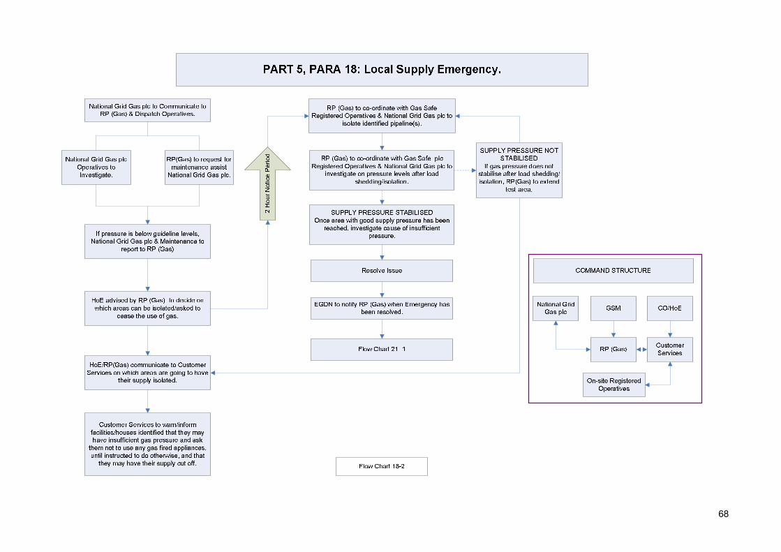
68
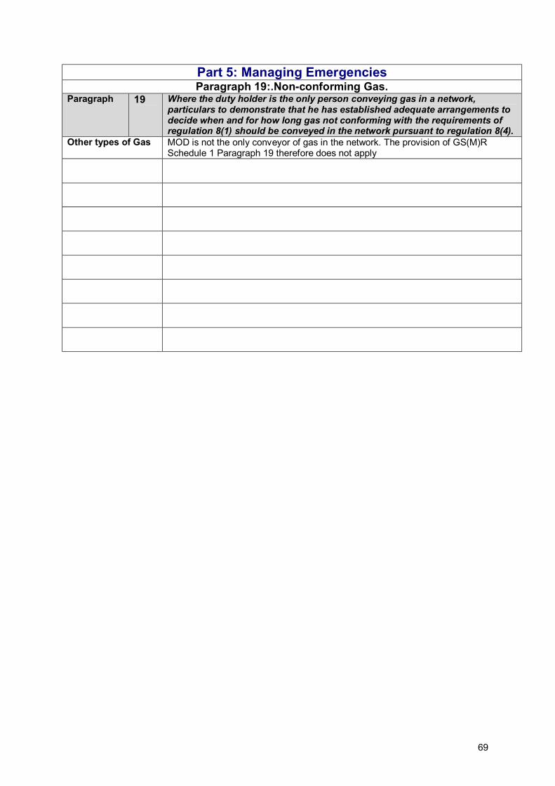
69
Part 5: Managing Emergencies Paragraph 19:.Non-conforming Gas.
Paragraph 19 Where the duty holder is the only person conveying gas in a network, particulars to demonstrate that he has established adequate arrangements to decide when and for how long gas not conforming with the requirements of regulation 8(1) should be conveyed in the network pursuant to regulation 8(4).
Other types of Gas MOD is not the only conveyor of gas in the network. The provision of GS(M)R Schedule 1 Paragraph 19 therefore does not apply

70
Part 5: Managing Emergencies Paragraph 21: Discontinuing Supply.
Paragraph 21 Without prejudice to paragraph 18 above, particulars of the procedures that the duty holder has established to discontinue safely, supply to consumers, when it is known there is insufficient gas to satisfy demand.
Sequence of Disconnection
Refer to Flow Chart 20-2 for further information.
High Priority Customers
As per Part 2, Para 2 Supply Critical facilities should be the last to be isolated, Refer to Flow Chart 20_1 for more information.
Supply Cut Notice Consumers must be given a 1-2 hour notice period. Compliance The site is populated by service personnel, MOD employees and other forces
dependent persons, non compliance with any request made by customer services will be addressed through the Employees Line Management/Command Structure.

71
PART 5, PARA 20: Interrupting Supply to Customers (1)
Network Supply Emergency Load Shedding Local Supply Emergency
Load Shedding
CO/HoE to authorise termination of supply for selected facilities.
Supply Critical Premises:Hospitals, Infirmaries,
Schools, Control Centres, etc.
Supply Non-Critical:Housing, Shopping Complexes, Offices.
Selection based on geographic location, supply critical or non
critical & usage rates.
RP (Gas) to decide on which areas can be isolated.
RP (Gas) ) to communicate to Customer Services on which areas are going to have their
supply isolated.
Customer Services to inform facilities/houses identified by
the RP (Gas) that they will have a gas supply cut, until
instructed otherwise.
Flow Chart 20_2
Flow Chart No. 20-1

72
PART 5, PARA 20: Interrupting Supply to Customers (2)
RP (Gas) to communicate to Customer Services on which areas are going to
have their supply isolated.
Customer Services to inform facilities/houses identified by the RP (Gas) that they will have a gas supply cut, until
instructed otherwise.
1-2 hour notice of gas supply cut.
Explanation that gas usage in this period would cause pressure safety switches to
be tripped.
Customer Services have a limited number of temporary heaters to be distributed to houses/facilities that have sufficient reason to warrant
one.
Arrange for Maintenance to visit properties that have
technical difficulties in switching off gas appliances.
Flow Chart No. 20-2

73
Part 5: Managing Emergencies Paragraph 21: Re-establish Supply.
Paragraph 21 Particulars of the procedures that the duty holder has established to restore safely the gas supply to consumers, following an interruption in supply.
System restoration Refer to Flow Chart 21_1 for further information The restoration process will be carried out in line with EGDN and MMO procedures and conducted in line with the “Protocol for Restoration of Gas Supplies2”. The EGDN responsible manager will have appropriate procedures in place, documented in EGDN/PR/E/3, for effective release of appropriate notification to all gas consumers
2 EGDN/PM/E/2

74

Annex A GENERIC RISK ASSESSMENTS
1- A
Part 3: Managing Safety Paragraph 5: Risk Assessment.
Risk Assessment
01 Any gas leak considered hazardous to persons or property (Under medium and/or low pressure conditions)
Date: xx/xx/xx
Any leak at any pressure can be quantified as a hazard. The higher the pressure and/or depending on the location of the leak the risk to the surrounding area varies Depending on the severity of the leak, other hazards such as explosions, fires, supply failures, pollution and associated financial implications could arise Depending on how quickly & thoroughly the gas leak is dealt with the resulting hazards from the incident will vary.
Risk
Damage to pipelines from digging Failure of control equipment Damage caused by general construction Corrosion of pipelines Failure of mechanical joints and seals Deterioration or rupture of pipeline Poor communication between involved parties can exacerbate the problem Length of response time by first responders
Caused By
Damage to pipelines caused by uncontrolled escaping gas Risk of causing a supply emergency Damage to persons & property Risk of Explosions & Fire Pollution of environment Purging maybe required after corrective action
Hazards Resulting from Risk
Permits to Dig Planned Preventative Maintenance Type & Quality control of materials used in gas network Strict adherence to emergency procedures in the event of an emergency Isolation via emergency stops Installation of gas network to industry standards
Current Preventative
Methods
Pressure monitoring More accurate gas network layout drawings Use of the gas safety management plan Training of all involved parties Training and simulated gas emergency drills
Further Required
Preventative Methods
In the event of a hazardous occurrence this RA must be audited, and updated Audits

Annex A
2- A
Part 3: Managing Safety Paragraph 5: Risk Assessment.
Risk Assessment
02 Fire or explosion near to, or directly involving, a pipeline or gas facility
Date: xx/xx/xx
Any fire or explosion directly involving a gas pipeline or facility could cause a major incident. Any fire or explosion near to a gas pipeline or facility may cause personal injury and or damage to property.
Risk
Undetected trapped gas Unresolved gas leaks Failure of control equipment, pipelines, seals, joints etc Damage to gas pipelines through digging and/or general construction Incorrect initial procedure when dealing with a gas leak Inadequate action by first responder
Caused By
Fire and/or explosions causing death and/or injury to general populous Damage and/or destruction of surrounding properties Damage to gas pipelines, gas control centres & other gas related equipment Disruption of gas supply Secondary Explosions & Fire resulting from inaction
Hazards Resulting from Risk
Scheduled Maintenance Designed for purpose Permits to Dig Strict adherence to emergency procedures, including ventilating and evacuating area
Current Preventative
Methods Pressure monitoring Use of the gas safety management plan Training and simulated gas emergency drills
Further Required
Preventative Methods
In the event of a hazardous occurrence this RA must be audited, and updated Audits

Annex A
3- A
Part 3: Managing Safety Paragraph 5: Risk Assessment.
Risk Assessment
03
A failure of operation of pipeline/plant onsite, or immediately downstream of site, that is maintained by the EGDN
Date: xx/xx/xx
Any incident directly involving the medium pressure pipelines onsite can only be dealt with by insert name of EGDN. In the event of a leak the response time by insert name of EGDN has an impact on the severity of the incident The level of cooperation and communication between EGDN and the onsite parties has an impact on the eventual severity of the incident
Risk
Poor response time by insert name of EGDN Poor communication between onsite parties and insert name of EGDN Poor coordination of onsite parties and insert name of EGDN Poor communication of procedures Lack of supply resulting in drop in supply pressure, resulting in site wide gas supply failure
Caused By
Disruption of gas supply to whole site Re-commissioning & purging after corrective action Re-ignition of non automatic ignition systems Long down time due to above hazards
Hazards Resulting from Risk
General communication between site and insert name of EGDN
Current Preventative
Methods Communication of site procedures to insert name of EGDN Understanding insert name of EGDN procedures Training and simulated gas emergency drills Training for quicker response time Pressure monitoring Planning for load shedding (reduces the risk of site wide gas failure) Fitting automatic ignition systems as standard Use of the gas safety management plan
Further Required
Preventative Methods
In the event of a hazardous occurrence this RA must be audited, and updated Audits
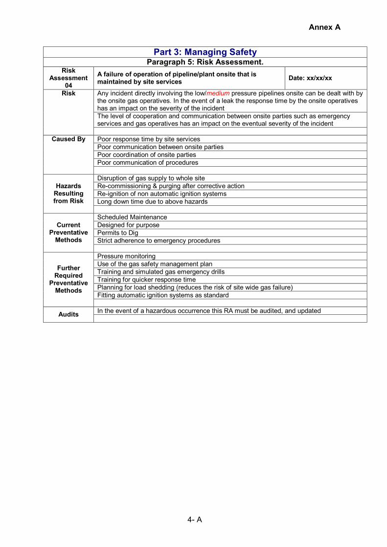
Annex A
4- A
Part 3: Managing Safety Paragraph 5: Risk Assessment.
Risk Assessment
04 A failure of operation of pipeline/plant onsite that is maintained by site services
Date: xx/xx/xx
Any incident directly involving the low/medium pressure pipelines onsite can be dealt with by the onsite gas operatives. In the event of a leak the response time by the onsite operatives has an impact on the severity of the incident The level of cooperation and communication between onsite parties such as emergency services and gas operatives has an impact on the eventual severity of the incident
Risk
Poor response time by site services Poor communication between onsite parties Poor coordination of onsite parties Poor communication of procedures
Caused By
Disruption of gas supply to whole site Re-commissioning & purging after corrective action Re-ignition of non automatic ignition systems Long down time due to above hazards
Hazards Resulting from Risk
Scheduled Maintenance Designed for purpose Permits to Dig Strict adherence to emergency procedures
Current Preventative
Methods Pressure monitoring Use of the gas safety management plan Training and simulated gas emergency drills Training for quicker response time Planning for load shedding (reduces the risk of site wide gas failure) Fitting automatic ignition systems as standard
Further Required
Preventative Methods
In the event of a hazardous occurrence this RA must be audited, and updated Audits

Annex A
5- A
Part 3: Managing Safety Paragraph 5: Risk Assessment.
Risk Assessment
05 Failure of safety critical equipment
Date: xx/xx/xx
Failure of safety critical equipment can have a severe impact on the safety of the gas network.
Risk
Lack of/or poor maintenance Incorrect use of equipment Ageing equipment
Caused By
Lack of control over gas network, resulting in a gas incident Lack of control over gas network during a gas incident
Hazards Resulting from Risk
Scheduled Maintenance Designed for purpose Regular operational training
Current Preventative
Methods Pressure monitoring Further training of gas operatives Replacing old equipment where required
Further Required
Preventative Methods
In the event of a hazardous occurrence this RA must be audited, and updated Audits

Annex A
6- A
Part 3: Managing Safety Paragraph 5: Risk Assessment.
Risk Assessment
06 Under-pressure in the gas system
Date: xx/xx/xx
If at any point the pressure in a gas network drops below a certain level, gas safety regulators will stop the flow of gas. These regulators are fitted to gas appliances and in some instances will also be downstream of the gas meter into individual houses. There is also a regulator on the main intake to the site. If the pressure in a gas network, leading into a house or facility, drops below a certain level a gas safety regulator will terminate the flow of gas. This will cause the pilot lights to be extinguished. On this site, due to the multitude of buildings and houses, it may take up to 3 days to re-ignite all the systems.
Risk
Gas leaks Poor gas network management Failure of Compressors Inadequate supply of gas in the system Failure of pressure control system
Caused By
Loss of gas supply Gas safety regulators being tripped (requires manually resetting on older models) Long recovery period Potential for air in the gas network
Hazards Resulting from Risk
Scheduled Maintenance Designed for purpose
Current Preventative
Methods Pressure monitoring Regular training of gas operatives Replacing old equipment where required Fitting automatic ignition systems as standard Replacing manual gas safety regulators with automatic cut-outs
Further Required
Preventative Methods
In the event of a hazardous occurrence this RA must be audited, and updated Audits

Annex A
7- A
Part 3: Managing Safety Paragraph 5: Risk Assessment.
Risk Assessment
07 Over-pressure in the gas system
Date: xx/xx/xx
If at any point the pressure in a gas network climbs above a certain level, gas safety regulators will stop the flow of gas. These regulators are fitted to gas appliances and in some instances will also be downstream of the gas meter into individual houses. There is also a regulator on the main intake to the site f the pressure in a gas network, leading into a house or facility, climbs above a certain level a gas safety regulator will terminate the flow of gas. This will cause the pilot lights to be extinguished. On this site, due to the multitude of buildings and houses, it may take up to 3 days to re-ignite all the systems.
Risk
Failure of pressure control system Incorrect pipe/valve sizing Blockages in system Poor gas network management
Caused By
Rupture of gas pipes due to high pressure related Damage to valves and other control equipment Damage to seals and joints Loss of gas supply
Hazards Resulting from Risk
Scheduled Maintenance Designed for purpose
Current Preventative
Methods Pressure monitoring Regular training of gas operatives Use of the gas safety management plan
Further Required
Preventative Methods
In the event of a hazardous occurrence this RA must be audited, and updated Audits

Annex A
8- A
Part 3: Managing Safety Paragraph 5: Risk Assessment.
Risk Assessment
08 Failure in system during load shedding
Date: xx/xx/xx
In the event of a gas supply emergency, load shedding can be used to stabilise the pressure in the system. However, if a section is isolated and the consumers on that branch use their gas supply the pressure in that branch will drop below acceptable levels and the pressure safety regulators will trip
Risk
Insufficient communication between onsite parties and the end user Insufficient means of monitoring pressure
Caused By
Loss of gas supply Gas safety regulators being tripped (requires manually resetting on older models) Long recovery period Potential for air in the gas network
Hazards Resulting from Risk
Current Preventative
Methods Better communication Pressure monitoring Use of the gas safety management plan Fitting automatic ignition systems as standard Replacing manual gas safety regulators with automatic cut-outs
Further Required
Preventative Methods
In the event of a hazardous occurrence this RA must be audited, and updated Audits

Annex A
9- A
Part 3: Managing Safety Paragraph 5: Risk Assessment.
Risk Assessment
09 General changes to the gas network
Date: xx/xx/xx
If during the design phase the sizing of the system is under/over sized, it could result in under/over pressure scenarios. If during the installation of a gas network, the work is not carried out to the relevant British Standards and if the work is not undertaken by operatives trained and skilled to the same British Standards, failure may take place.
Risk
Incorrect pipe sizing at design phase Underestimating impact on overall site gas supply Incorrect installation of plant and pipelines Under qualified gas operatives used for gas works
Caused By
Damage to pipelines and gas network plant and equipment Risk of causing a supply emergency Damage to persons & property Risk of Explosions & Fire
Hazards Resulting from Risk
Using trained individuals to carry out work to the gas network Checking credentials of design authority for gas network redesign
Current Preventative
Methods Monitoring competence of gas network operatives Use of the Gas Safety Management Plan Further checking/commissioning of completed works
Further Required
Preventative Methods
In the event of a hazardous occurrence this RA must be audited, and updated Audits

Annex A
10- A
Part 3: Managing Safety Paragraph 5: Risk Assessment.
Risk Assessment
10 Failure through PPM, general operation of the gas network plant/equipment and safety inspections
Date: xx/xx/xx
Inadequate action during maintenance can cause failure in the system If safety inspections are not carried out regularly, the system may be vulnerable to failure The day to day operation of the system is vital to the overall performance of the gas network. If the day to day operation is not undertaken to industry standards, the gas network could be vulnerable to failure
Risk
Gas plant & pipelines are not sufficiently maintained Scheduled activities do not take place. Operatives are insufficiently trained Inadequate co-ordination of operation Inadequate communication between onsite parties Inadequate planning of scheduled activities Inadequate inspection and testing of equipment
Caused By
Damage to pipelines and gas network plant and equipment Risk of causing a supply emergency Damage to persons & property Risk of Explosions & Fire
Hazards Resulting from Risk
Monitored and maintained Using trained individuals to carry out work to the gas network Following PPM schedules to carry out works Awareness Training, drills and exercise Using qualified operatives
Current Preventative
Methods
Monitoring competence of gas network operatives Checking credentials of design authority for gas network redesign Employ better lines of communication between parties Compliance with the Gas Safety Management Plan
Further Required
Preventative Methods
In the event of a hazardous occurrence this RA must be audited, and updated Audits

Annex A
11- A
Part 3: Managing Safety Paragraph 5: Risk Assessment.
Risk Assessment
11 Emergency Shutdowns
Date: xx/xx/xx
Emergency shutdowns can be used in the event of a gas incident which warrants the gas network or part thereof to be shut down. If this process fails, it can have a severe impact on the resolution of the incident
Risk
Failure of emergency shutdown valves Ageing emergency shutdown valves Lack of sufficient facilities for segregated shutdowns
Caused By
Escalating hazard cause by existing emergency Damage to pipelines and gas network plant and equipment Risk of causing a supply emergency Long down time
Hazards Resulting from Risk
Current Preventative
Methods
Use of the Gas Safety Management Plan Providing strategically placed emergency shutoff valves Scheduled PPM Checking credentials of design authority for gas network redesign Replacing old equipment where required
Further Required
Preventative Methods
In the event of a hazardous occurrence this RA must be audited, and updated Audits

Annex A
12- A
Part 3: Managing Safety Paragraph 5: Risk Assessment.
Risk Assessment
12 Interface with Gas Transporter
Date: xx/xx/xx
If interfaces between the site team and the gas transporter are not managed carefully, the fallout from gas incidents can become more pronounced
Risk
Poor response time by EGDN Poor communication between onsite parties and EGDN Poor coordination of onsite parties and EGDN Poor communication of procedures
Caused By
Damage to pipelines Resultant hazards from any gas incident can escalate Risk of causing a supply emergency Damage to persons & property Risk of Explosions & Fire
Hazards Resulting from Risk
Current Preventative
Methods
Communication of site procedures to EGDN Understanding EGDN procedures Training and simulated gas emergency drills Regular communication through fixed procedures
Further Required
Preventative Methods
In the event of a hazardous occurrence this RA must be audited, and updated Audits

Annex A
13- A
Part 3: Managing Safety Paragraph 5: Risk Assessment.
Risk Assessment
13 Interface with Customer
Date: xx/xx/xx
If communication between the site team and the end user are not carefully established, the fallout from gas shortages could result in the system having to be purged and the pilot lights re-ignited. On a large site such as this, it could take up to three days to re-ignite all pilot lights.
Risk
Poor communication Lack of understanding No method of checking on gas usage
Caused By
Risk of causing a supply emergency Loss of pressure in system Long recovery period Potential for air in the gas network
Hazards Resulting from Risk
Current Preventative
Methods
Pressure monitoring system Use of the Gas Safety Management Plan
Further Required
Preventative Methods
In the event of a hazardous occurrence this RA must be audited, and updated Audits

Annex A
14- A
Part 3: Managing Safety Paragraph 5: Risk Assessment.
Risk Assessment
14 Interface with Emergency Services
Date: xx/xx/xx
The first responder has a duty to minimise the risk to the surrounding area upon arrival. If the gas incident is within a enclosed area, isolating the system is the correct course of action. However in a open, well ventilated area, isolating the system may not be necessary, and could cause secondary hazards
Risk
Poor communication Lack of understanding
Caused By
Risk of causing a supply emergency Causing the need to purge systems Long downtime of gas network
Hazards Resulting from Risk
Current Preventative
Methods
Providing training to the Emergency Services, so that they will be able to better tackle gas incidents
Further Required
Preventative Methods
In the event of a hazardous occurrence this RA must be audited, and updated Audits

Annex A
15- A
Part 3: Managing Safety Paragraph 5: Risk Assessment.
Risk Assessment
15 Natural Disasters, civil disturbances, other unforeseeable events
Date: xx/xx/xx
The risk of unforeseeable events causing gas related incidents cannot be planned for. However it is possible to minimise the impact of the resulting hazards
Risk
Explosions Ground tremors Gas pipe sabotage
Caused By
Damage to pipelines caused by uncontrolled escaping gas Risk of causing a supply emergency Damage to persons & property Risk of Explosions & Fire Pollution of environment Purging maybe required after corrective action
Hazards Resulting from Risk
High security levels
Current Preventative
Methods
Use of the Gas Safety Management Plan
Further Required
Preventative Methods
In the event of a hazardous occurrence this RA must be audited, and updated Audits

Annex B
1 - B
Inspections and Investigations by External Authorities The Pipeline Safety Regulations (PSR) Gas Safety Management Regulations (GSMR) Gas Safety (Installation and Use) Regulations 1998 (GS(I&U)R) When the GSMR and the PSR introduced, gas safety enforcement was in the interests of clarity split between HSE-FOD and HSE-HID. The deliberate decision was taken to provide a definite cut-off point between these two sets of regulations and the GS(IU)R,. This point was set as the outlet of the first emergency control intended for consumers' use, as defined in GSIUR (see definition of 'pipe' in GSMR reg.2 (1), and definition of 'pipeline for supplying gas to premises' in PSR reg.3 (4)). Both the GSMR and the PSR extend up to, and include, this emergency control, and although the GS(IU)R contains provisions related to emergency controls, these controls are not included in the definition of ‘gas fittings’ in GS(IU)R, (reg.2(1)). Under the following legislation the identified Authorities have a statutory duty to undertake investigations into gas incidents including those on the Defence Estate Regulation Area of Responsibility Enforcing Authority The Pipeline Safety Regulations
Upstream of and including the emergency control valve (ECV)
Health and Safety Executive’s (HSE) Hazardous Installations Directorate (HSE-HID)3.
Gas Safety Management Regulations
Upstream of and including the emergency control valve (ECV)
HSE - HID
Gas Safety (Installation and Use) Regulations 1998 (GS(I&U)R)
Downstream of the emergency control valve (ECV)
HSE Field Operations Directorate (HSE-FOD)
The Gas Safety (Rights of Entry) Regulations 1996 (GS(RoE)R) confer rights of entry upon "public gas transporters" and "relevant authorities" to enter premises for the purpose of preventing gas escapes, the examination and disconnection of "gas fittings" and other related purposes All carbon monoxide incidents resulting from the use of faulty gas appliances are dealt with by HSE-FOD inspectors under GS(IU)R. (see Annex G for information on Carbon Monoxide) Though carbon monoxide incidents (CO) are for HSE-FOD inspectors to investigate, the GSMR places gas suppliers (essentially those who bill consumers for their gas) under a duty to arrange for investigations to be carried out by competent persons (whether by themselves, or through others that they have contracted to act on their behalf) into all such incidents that are notifiable under RIDDOR reg.6(1) (GSMR reg.7(14)); In determining which part of the HSE investigates gas fires or explosions; the key issue is to establish the source of the leak. If it was from the main or service outside the premises (i.e. upstream of the ECV) which has tracked into the house and subsequently ignited, then the investigation should be with HSE-HID. However, if the source is anywhere downstream of the ECV
3 The exceptions to this are incidents of third party damage to pipelines. In most cases, this stems from the activities of other utilities, agricultural or construction works. As these activities are generally looked after by HSE-FOD (including the Construction Division), it has been agreed that although local HSE-FOD and HSE-HID inspectors should liaise on any third-party interference damage incidents, in general, FOD inspectors will take the lead in investigating such incidents. HSE-HID specialist pipelines inspectors will provide technical support to HSE-FOD where necessary.

Annex B
2 - B
(e.g. from a pipework joint within the premises) the investigation should be carried out by HSE-FOD. In reality, it may not be immediately possible to determine the source of the leak, it has therefore been agreed by the HSE that HSE-FOD inspectors4 will normally deal with all initial reports of fires or explosions. However, should it become clear that the source of the escape was upstream of the ECV; the investigation will be passed to HSE-HID. In most domestic premises there will be only one emergency control valve, normally situated immediately alongside the consumer's meter. However, in the case of multiple occupancy accommodation (i.e. blocks of flats) or commercial/industrial sites there may be several such controls, for use by individual consumers. In such situations, it is the first emergency control for the premises/site for consumers to isolate the gas supply to the premises or site as a whole, in case of emergency, that determines the divide between GS(IU)R and GSMR/PSR, and the enforcement responsibilities of HSE-FOD and HSE-HID inspectors. The Gas Safe Register has a team of inspectors who monitor that gas work is being undertaken competently and safely. They deal with reactive complaints, undertake planned inspections and handle ad hoc requests. The Gas Safe Register inspectors work closely with the regulators such as HSE.
4 FOD inspectors are generally responsible for enforcing gas safety matters downstream from the emergency control of consumers' meters (covered by the Gas Safety (Installation and Use) Regulations 1998 (GSIUR)), whereas HID inspectors are responsible for enforcing those matters upstream of these emergency controls, related to the safe transmission and distribution of gas at high, medium, and low pressure, (covered by both the Gas Safety (management) Regulations 1996 (GSMR) and the Pipeline Safety Regulations 1996 (PSR)).

Annex C
1 - C
DIO AND MMO H&S POLICY AND ORGANISATION AND ARRANGEMENTS FOR THE MANAGEMENT OF GAS NETWORKS Copy of the H&S policy statements of the DIO and MMO CHIEF EXECUTIVE DEFENCE INFRASTRUCTURE ORGANISATION’S SAFETY, HEALTH, AND ENVIRONMENTAL PROTECTION ORGANISATION & ARRANGEMENTS STATEMENT (Part A) INTRODUCTION 1. Overall responsibility for safety5, health and environmental protection (SHEP) within the Ministry of
Defence rests with the Secretary of State for Defence (SofS) as detailed within his “Health, Safety and EP in Defence” Policy Statement and Joint Service Publication (JSP)815.
2. MOD wide S&EP performance targets are defined in the Defence Plan: that is to minimise work-related
fatalities, injuries, ill-health and effects on the environment (no statistically significant increase in fatalities over a rolling 12 month period; reduction of [accident incidence] rate of major injuries from previous year; and reduction in number of significant environmental incidents); and to attain and maintain Level 4 against MOD Safety & EP Sub-Strategy Goals6 by Mar 14.
3. The SofS delegates responsibility for ensuring effective management arrangements are in place to
achieve his expectations to the Permanent Under Secretary (PUS) who in turn delegates authority for the discharge of responsibilities and conduct of activities to individual TLB Holders and TFA Chief Executives within their respective areas of responsibility.
4. The PUS ensures TLB/TFA compliance with the above through the Holding to Account Process and the
Annual S&EP Assurance Reports made to the Director Defence Safety and Environment Authority. REQUIREMENT 5. As Chief Executive (CE) of the Defence Infrastructure Organisation (DIO) and TLB Holder, I am
responsible for all SHEP matters within DIO; both occupational and in the delivery of infrastructure and infrastructure related services. In accordance with the SofS Policy Statement this O&A Statement sets out my SHEP objectives, the organisation and arrangements to be implemented across DIO and reflects the personal importance I attach to:
a. the health, safety and general well-being of all DIO employees, contractors and those who may be
affected by our work activities (e.g. site users; members of the public, etc), b. the protection of the environment, c. achieving and maintaining compliance with S&EP legislation, MOD policy and Defence targets in the
UK and overseas, and d. the provision of assurance to SofS that those areas of MOD infrastructure and estate utilised by
Visiting Forces are being appropriately managed in line with established host nation principles. OBJECTIVES AND GENERAL DUTIES 6. Although ultimate responsibility for SHEP management rests with me, responsibility for associated duties
is cascaded down through my Executive Committee members, who I will hold accountable, and through them to the manager or individual responsible for the activity. It is therefore essential that managers and their teams work closely together in the implementation of robust SHEP Management Systems, that each and everyone takes a personal responsibility in ensuring that all SHEP risks are kept to as low as is reasonable practicable.
7. This approach is in accordance with MOD Policy and general SHEP organisation and arrangements for
ensuring compliance with the Health and Safety at Work, etc Act and Environmental Legislation as described in JSP’s 375 and 418 respectively.
5 Safety includes fire safety, equipment safety, material safety and occupational health 6 Goals 1 to 5: A Learning Organisation; Leadership and Culture; Competence; Hazards and Risks; Compliance with Legislation and MOD Regulations.

Annex C
2 - C
8. I require all staff to be fully aware of their responsibilities in the implementation of the following objectives within their day-to-day activities and areas of responsibility;
a. Leading by example and demonstrating a commitment to health, safety (H&S) and Environmental
Protection (EP) excellence by the promotion of a positive culture toward safety and protection of the environment;
b. Ensure that all SHEP risks resulting from our occupation or activity, including organisational change, are: i) Fully assessed, justified and regularly reviewed to ensure underlying assumptions are robustly
tested and revised where necessary; ii) Kept as low as is reasonably practicable; iii) Allocated resources as an integral part of any planning or decision making process; iv) Escalated up the chain of command prior to the implementation of controls where higher
authority to accept or deviate is required; c. All staff and those we engage are suitably informed of the hazards, risks and control measures
affecting their work and are suitably qualified and experienced (SQEP) and competent to discharge their duties effectively and safely;
d. So far as is reasonably practicable, all staff are provided with safe workplaces, safe systems of work, safe equipment and safe working environment;
e. Conduct our activities in a way that ensures that risks to our staff, the environment and others that may be affected by our activities, are assessed and controlled proportionately with the specific aim to minimise work-related accidents, ill-health and prevent pollution;
f. The requirements of all applicable MOD Regulation and United Kingdom legislation are complied with, along with any additional requirements from international treaties and protocols governing DIO’s overseas activities and those of Visiting Forces utilising MOD infrastructure and estate. When overseas we will apply UK standards where reasonably practicable, and in addition comply with relevant host nations’ standards that exceed UK requirements;
g. Implement the MOD Safety and EP Sub-strategy and related Strategic Objectives within the Defence Infrastructure Command Plan so as to meet SofS expectations and continually improve our SHEP management systems and performance;
h. Encourage the open and honest reporting of all staff/contractor accidents, incidents and near misses and investigate these to the required level to ensure all causes are understood, lessons are identified and promulgated and remedial actions taken;
i. To have in place processes and management systems that provide for effective monitoring and reporting of SHEP performance and continuous improvement;
j. All employees of DIO and its Industry Partners are encouraged to contribute to a positive culture of health, safety and environmental protection and consulted upon on matters that may affect their health, safety or welfare.
The arrangements for DIO and how it organises itself to achieve its SHEP management objectives are set out in Part B of this O&A Statement
Andrew Manley Chief Executive Defence Infrastructure Organisation 17 June 2013

Annex C
3 - C
CHIEF EXECUTIVE DEFENCE INFRASTRUCTURE ORGANISATION’S SAFETY, HEALTH, AND ENVIRONMENTAL PROTECTION ORGANISATION & ARRANGEMENTS STATEMENT (Part B)
MOD DUTY HOLDER CONSTRUCT (RISKS TO LIFE) 1. In addition to the general duties in “Part A” of the O&A statement, the sections which follow set out how
DIO organises itself to achieve its SHEP management objectives and where specific responsibilities are assigned ensuring there is an effective governance framework for all staff and contractor activities.
2. References to the “Duty Holder Construct” refer to a MOD-wide governance regime that compliments
normal delegation of duties to ensure that critical safety requirements (e.g. risks to life) are organised by those directly affected by the implications of failure, e.g. those persons who carry personal and legal responsibility and accountability for mitigating and making judgements on safety risks within the TLB defined area of responsibility.
3. DIO has defined Duty Holder appointments and Duty Holder facing roles at various levels of the
organisation. Both Duty Holder responsibilities and Duty Holder facing roles are defined in the relevant sections below.
CHIEF EXECUTIVE 4. By appointment as Chief Executive, TLB Holder and Senior Duty Holder under the MOD “Duty Holder
Construct”, I am personally responsible, and accountable to PUS, for ensuring the following for all activities in, and the capabilities provided by, DIO:
a. As Senior Duty Holder, I am responsible for ensuring an effective end-to-end safety management
system is resourced, implemented and appropriately managed across the TLB. b. That resources are adequate to conduct activities safely and without harm to the environment; c. That effective SHEP management arrangements are implemented and maintained; d. That personnel under my control are suitably qualified, trained and equipped; e. That risks outside my level of control, authority or competence are escalated to PUS prior to
implementation of any process or activity; f. Any organisational change is properly assessed and demonstrated not to be detrimental to SHEP
before being implemented, and that implementation is suitably managed and communicated. 5. I am responsible for final approval of SHEP key performance indicators within the DICP and Annual
SHEP Assurance Report to Director Defence Safety & Environment Authority (DDSEA) and the DIO Audit Committee. I will ensure that the SofS is notified in writing of any fatality which is potentially safety-related as soon as possible.
6. As required by the MOD construct, I have appointed the Chief Operating Officer (COO) and Head
Programme and Project Delivery as the Operating Duty Holders for the operational aspects of DIOs business.
CHIEF OPERATING OFFICER 7. By appointment as Chief Operating Officer and Operating Duty Holder under the MOD Duty Holder
construct, COO is personally responsible, and accountable to me (CE DIO), for all Service Delivery aspects of the business. This will be facilitated through his chairmanship of the Operational Committee (OCIB). He will ensure the following within his area of responsibility:
a. As Operating Duty Holder, be responsible and accountable to the Senior Duty Holder for ensuring
that the TLB delivers a fit-for purpose7 estate and services. Also that our Industry Partners have appropriate Health and Safety arrangements in place to minimise Risk to Life from activities under their control;
b. Resources are adequate to conduct activities safely and without harm to the environment; c. That effective SHEP management arrangements are implemented and maintained; d. That personnel under his control are suitably qualified, trained and equipped;
7 Fit for purpose means legally compliant and safe when used for its intended purpose

Annex C
4 - C
e. Risks outside his level of control, authority or competence are escalated to me (CE DIO) prior to implementation;
f. Any organisational change within his Area of Responsibility is properly assessed and demonstrated not to be detrimental to SHEP before being implemented, and that implementation is suitably managed and communicated;
g. DIO Heads of Establishments are appointed for all establishments under our control (including the raining estate).
h. Suitable and sufficient competent persons are provided to support the safe delivery and use of the training estate in accordance with JSP 375 and JSP 403 requirements.
i. That Area Managers act in a Duty Holder facing capacity to Heads of Establishment (as Delivery Duty Holders) for service delivery aspects under their control.
8. COO will also appoint (with a letter of authority) Head of Service Delivery Training as a Delivery Duty
Holder (DDH) who will be responsible for:
a. Ensuring that suitable and sufficient arrangements and competent personnel are provided for the delivery of the Safe Place to Train on the ranges and training areas in the UK and overseas that DIO is responsible for, in accordance with JSP 375 and JSP 403.
b. Providing the Head of Establishment responsibilities across the Ops Training portfolio; c. Managing the Risk to Life activities involved in the delivery of explosive storage and safety across
the Ops Training portfolio.
9. In addition to the DDH duties, Head of Service Delivery Training will act in a Duty Holder facing capacity for training issues. Noting that range licencing is carried out by Support Command in accordance with JSP 403, Head of Service Delivery Training is to undertake the Intelligent Client role and functional lead for all other aspects of the Safe Place to Train for MOD training areas and ranges, that DIO is responsible for. MOD range and training area users retain responsibility (as activity Duty Holders) for safe practice - the control and conduct of training activities. They are responsible for ensuring that the Safe Place is used in accordance with the relevant standing orders and use instructions.
10. Under internal arrangements, COO will in addition:
a. Implement and operate MOD JSP 375 Volume 3 (Safety Rules and Procedures (SRPs) within all Service Delivery areas;
b. Ensure that an ISO 14001 based or appropriate EMS is operated on sites where DIO is Head of Establishment;
c. Ensure industry partners operate an ISO 14001 based or equivalent EMS. HEAD PROGRAMME AND PROJECT DELIVERY 11. By appointment as Head Programme and Project Delivery and Operating Duty Holder under the MOD
Duty Holder construct, Hd PPD is personally responsible, and accountable to me (CE DIO), for Programme and Project Delivery aspects of the business. He will ensure the following within his area of responsibility:
a. As Operating Duty Holder, be responsible and accountable to the Senior Duty Holder for ensuring
that activities carried out by our Industry Partners have appropriate Health and Safety arrangements in place to minimise Risk to Life from activities under their control.
b. Resources are adequate to conduct activities safely and without harm to the environment; c. That effective SHEP management arrangements are implemented and maintained; d. That personnel under his control are suitably qualified, trained and equipped; e. Risks outside his level of control, authority or competence are escalated to me (CE DIO) prior to
implementation; f. Any organisational change within his Area of Responsibility is properly assessed and demonstrated
not to be detrimental to SHEP before being implemented, and that implementation is suitably managed and communicated;
g. DIO Heads of Establishments are appointed for sites in disposal where required by the assessment process.
h. That Project Managers act in a Duty Holder facing capacity to Heads of Establishment (as Delivery Duty Holders) for projects under their control.
HEAD OPERATIONS DEVELOPMENT AND COHERENCE (ODC)
Annex C
5 - C
12. By appointment as Hd ODC is personally responsible and accountable to me (CE DIO), for the
Operations Development and Coherence aspects of the business. His responsibilities as a member of the Executive Committee (ECIB) are detailed under the ECIB Section.
13. In addition he is nominated as Duty Holder facing for pan Departmental strategic programmes and
as such is responsible for providing support to the relevant activity Duty Holder. He will ensure the following within ODC:
a. The Engineering and Construction lead is responsible for:
i) The appointment of suitable and sufficient Senior Authorising Authorities, and deputies, necessary to compile, maintain and oversee the effectiveness and applicability of JSP 375 Vol 3 governing DIO/infrastructure significant risk activities.
ii) Resourcing of formal requests to support SHEP policy development and provide functional subject area advice on SHEP related activities
iii) Ensuring H&S advisors are appointed for each operational/delivery area
b. The Co-ordinating Senior Authorising Authority (CSAA)/H&S coordinating Lead is responsible for: i) Maintaining the “common requirements” elements of JSP375 Vol 3 and ensuring coordination
and cooperation across the SAA’s and their deputies; ii) Championing the development, continual improvement and maintenance of JSP 375 Vol. 3; iii) Providing specialist advice and support on safe systems across DIO; iv) Notifying the DIO Chief Safety Advisor (CSA) of any significant failure to discharge the duty
imposed by JSP 375 Vol. 3, on any part of the defence estate; v) Championing the improvement and development of a collaborative working culture and
continued professional development of the SAA/AE community; vi) Advising the Engineering & Construction Lead on SAA appointments; vii) Reviewing results of monitoring and audit reports by the SAA, Coordinating Authorised Engineer
and AE communities and reporting to the appropriate authority any deficiencies found; viii) Acting as custodian for JSP375 Vol 3 on behalf of Director DSEA and ensuring its applicability,
currency and upkeep; ix) Liaising with OGD, the HSE and non-government organisations.
c. Senior Authorising Authorities are the focal point for the management and implementation of the chapter JSP 375 Vol 3 applicable to their specialism. Their responsibilities include: technical audits; assessment of Authorising Engineers; audit of systems; review of legislation and acting as competent person overseeing related incident investigations.
d. Health and Safety Advisors are responsible for:
i) the provision of professional Health and Safety advice to Service Delivery and Programme and Project Delivery
ii) Undertaking assurance activities to populate the DIO Risk Profile and provide assurance through the Duty Holder construct.
iii) Undertaking Accident/incident investigation reporting & recording iv) Supporting policy development in line with agreed programmes
HEAD SECRETARIAT 14. Head of Secretariat (Hd Sec) will undertake the role of DIO Safety and Environment Champion and is
accountable to me for the development, maintenance and promulgation of corporate SHEP policies, instructions, guidance and processes. Other duties include:
a. Advise the ECIB on effective safety and environment objectives, standards, measures, and
performance indicators including the safety elements of MOD Safety and EP Sub Strategy. b. Provide independent assurance and report performance to the ECIB that Health and Safety and
Environmental legislation, codes of practice, and MOD/DIO policies are being fully complied with. c. Appoint the Chief Safety Advisor (CSA DIO) d. Provide policy direction on all SHEP disciplines across DIO and developing and maintaining
consistent systems of policies, instructions and guidance. e. Coordinate the production of the TLB Annual SHEP Assurance Report to the ECIB in line with the
Holding to Account, DIO AC and Director DSEA reporting requirements.

Annex C
6 - C
HEALTH AND SAFETY ASSURANCE 15. The Principal Safety Advisor will provide a H&S “Head of Profession” focus within DIO and be
responsible for the following in support of my SHEP management responsibilities:
a. Provision of independent professional advice and oversight of H&S processes on behalf of SDH and ODH’s, and other TLB’s and internal/external regulatory authorities;
b. Provision of independent audit and verification of DIO H&S processes to SDH and ODH’s, and other TLB’s and internal/external regulatory authorities;
c. Undertake high-level stakeholder engagement with internal and external regulatory bodies; d. Policy development and delivery for the infrastructure domain in consultation with or on behalf of
Director DSEA; e. Delivery of the H&S elements of DIO’s input into the Defence Infrastructure Command Plan; Holding
to Account Process and TLB SHEP Annual Assurance Report to Director DSEA and the DIO Audit Committee;
f. Represent CE DIO at MOD Regulator SHEP Stakeholder Committees. 16. The Coordinating Safety Assurance Officer will support the Principal Safety Advisor with responsibility for
the following:
a. Liaison and functional linkage with the DIO H&S Advisor network embedded in Head ODC (Engineering and Construction);
b. Liaison with Head ODC, the Engineering and Construction team, Senior Authorising Authorities and technical/specialist safety community (engineering and significant risk areas);
c. Coordination of assurance on infrastructure technical and operational worthiness; d. Provision of assurance of H&S competency standards and continuing professional development; e. Support to ensure coherence across infrastructure functions and domains.
17. The Chief Safety Advisor (CSA) is responsible for development and maintenance of DIO H&S policies,
instructions, targets, guidance and working practices (including safe systems of work). The CSA will:
a. Provide professional H&S advice to Principal Safety Advisor, CE DIO, ECIB8/OCIB9, DIO Change Programmes, DIO staff, and professional guidance to the DIO Safety Advisor community in a timely manner;
b. Provide necessary assurance that the organisation is discharging its H&S obligations; c. Advise on the H&S elements of the MOD S&EP Sub-Strategy, Holding to Account Process and
Annual Assurance Reports; d. Undertake formulation, implementation and maintenance of TLB H&S policies, instructions and
guidance – including assessing the implications of any new legislation or policy affecting DIO activities;
e. Be the focus for H&S within the organisation and interface with internal/external regulators; H&S forums and other organisations possessing specialist knowledge beneficial to the overall H&S policy of DIO;
f. Undertake investigations into serious accidents, incidents and near misses with H&S implications; g. Be the assurance authority for DIO and contractor compliance with relevant legislation and
MOD/DIO policy. h. Co-ordinate, analyse and corporately report SHEP accidents or incidents in accordance with MOD
policy; i. Represent DIO to DSEA and lead on DIO SHEP audit and assurance; j. Be the focal point for safe systems for other government departments, the Health & Safety Executive
and other Non–Government Organisations; k. Be the focal point for DIO Health and Safety matters for MOD & other government departments e.g.
Joint Liaison Committee. ENVIRONMENTAL PROTECTION ASSURANCE 18. SAPT Deputy Head Policy will provide an EP focus and be responsible for the following in support of my
SHEP management responsibilities: 8 ECIB – Executive Committee of the Defence Infrastructure board 9 OCIB – Operational Committee of the Defence Infrastructure Board

Annex C
7 - C
a. Co-ordination of independent professional advice and oversight of EP processes on behalf of myself SDH and ODH’s, and other TLB’s and internal/external regulatory authorities;
b. Provision of independent audit and verification of DIO EP processes to SDH and ODH’s, and other TLB’s and internal/external regulatory authorities;
c. Undertake high-level stakeholder engagement with internal and external regulatory bodies; d. Policy development and delivery for the infrastructure domain in consultation with or on behalf of
Director DSEA; e. Delivery of the EP elements of DIO’s input into the Defence Infrastructure Command Plan; Holding
to Account Process and TLB SHEP Annual Assurance Report to Director DSEA and the DIO Audit Committee;
f. Represent CE DIO at MOD Regulator SHEP Stakeholder Committees. 19. SAPT AD Environmental Compliance is DIO's EP practitioner, responsible for development and
maintenance of DIO EP policies, instructions, targets, guidance and working practices. AD EnvCompl will:
a. Provide the focal point for EP advice to CE DIO, ECIB/OCIB, DIO staff, and professional guidance to
the DIO EP advisor community in a timely manner; b. Provide necessary assurance that the organisation is discharging its EP obligations; c. Act as an advisor on the EP elements of the MOD S&EP Sub-Strategy, Holding to Account Process
and Annual Assurance Reports; d. Undertake formulation, implementation and maintenance of TLB EP policies, instructions and
guidance – including assessing the implications of any new legislation or policy affecting DIO activities;
e. Be a focus for EP within the organisation and interface with internal/external regulators; EP forums and other organisations possessing specialist knowledge beneficial to the overall EP policy of DIO;
f. Undertake investigations into serious incidents and near misses with EP implications; g. Be the assurance authority for DIO and contractor compliance with relevant legislation and
MOD/DIO policy. h. Co-ordinate, analyse and corporately report EP accidents or incidents in accordance with MOD
policy; i. Be the focal point for EP for other government departments; j. Be the focal point for DIO EP matters for MOD & other government departments e.g. Joint Liaison
Committee. MEMBERS OF THE EXECUTIVE COMMITTEE OF THE DEFENCE INFRASTRUCTURE BOARD (ECIB) 20. The ECIB is the “decision-making” body within DIO constituted to assist me in the exercise of my
responsibilities as TLB Holder, Senior Duty Holder and Accounting Officer. As such, members are both collectively accountable to me for the implementation of SHEP policy across the organisation as well as individually for performance within their respective business areas.
21. In addition to my objectives, ECIB members are to undertake the following within their respective
business areas. and take due cognisance of corporate policies, targets and affected stakeholder requirements:
a. Ensure resources are adequate to conduct activities safely and without harm to the environment; b. Ensure that effective SHEP management arrangements are implemented, maintained and
communicated; c. Ensure that personnel under your control are suitably qualified, trained and equipped; d. Ensure that managers at every level receive appropriate training and have at their disposal adequate
resources to meet the organisations statutory and departmental obligations; e. Take responsibility for the safety and environmental implications resulting from any business
decisions they make; f. As part of business as usual, promote and lead by example on SHEP and create a culture were
everybody understands and delivers their contribution to protecting people and the environment; g. Ensure this statement and all DIO and MOD SHEP policy and guidance are brought to the attention
of their staff and others, including industry partners, who might be affected by them; h. Document how SHEP hazards/risks are to be systematically and pro-actively identified and
controlled, and ensure that processes are in place so that hazards and risks resulting from DIO activities are communicated and controlled;

Annex C
8 - C
i. Risks or concerns outside their level of control, authority or competence are escalated to me, or the relevant ODH where these are safety critical or present a risk to life, prior to the implementation of any process or activity;
j. Any change in directorate organisation or arrangements is properly assessed and demonstrated not to be detrimental to SHEP before being implemented, and that implementation is suitably managed and communicated;
k. Where required develop and implement an EMS and make appointments as appropriate; l. Monitor and report staff and contractors’ compliance with legislation and MOD/DIO policy; m. Ensure that staff and contractor accidents, incidents and near misses are reported/notified and
investigated in accordance with MOD/DIO Policy, RIDDOR10, and contractual requirements; n. Have regular liaison with DIO’s contractors regarding their safety arrangements; o. Set any underlying directorate SHEP objectives and targets and allocate adequate resources to
deliver them; p. Involve, and encourage staff participation at all levels, and foster and promote a positive SHEP
culture; q. Report performance against objectives including performance of contractors’ health safety and
environmental management systems as necessary; r. Appoint a SHEP focal point for each DIO occupied area or building. s. Nominate functional leads to represent CE DIO at MOD Regulator SHEP Stakeholder Committees.
HEADS SERVICE DELIVERY OVERSEAS; UK; TRAINING AND ACCOMMODATION; HEAD GUARDING AND HEAD NGEC/HESTIA 22. The responsibilities listed for ECIB members above equally apply to Heads in the “Operations” group
and Head NGEC/HESTIA but they are directly accountable to COO for all aspects of SHEP performance and risk escalation within their respective business areas.
23. In addition Head SD UK will monitor and report on Visiting Forces’ observance of host nation statutory
requirements and MOD /DIO policy requirements in respect of the MOD infrastructure and estate they utilise.
DIO DEPUTY HEADS OF SERVICE DELIVERY; GUARDING; NGEC/HESTIA AND PROGRAMME AND PROJECT DELIVERY 24. The Deputy Head is the DIO officer in charge of DIO’s projects/activities and is accountable to the
respective Head for specific operations or activities on the defence estate primarily at the point where they interface with the estate users. Deputy Heads shall:
a. Make effective arrangements to ensure that prior notification of all contract work is given to the
CO/HofE (or their nominated representative) to allow for the provision of suitable and sufficient information, instruction and arrangements necessary to enable statutory obligations to be met and contractual operations to be performed safely, without risks to health, safety and/or environment;
b. Put in place suitable SHEP management systems and procedures for all contracts placed on his or her behalf to establish that the appointed contractors and their sub-contractors are competent and able to perform their tasks safely and consider impact upon the environment. Monitor that they operate within a safe system of work, and where specified, MOD Policy;
c. Require JSP375 Volume 3 to be implemented by their staff, contractors and their subcontractors where they apply;
d. Prior to work commencing on site, require their contractors, in combination with CO/HoE, to receive an up to date SHEP briefing relevant to the contracted undertaking;
e. Ensure that effective local SHEP management arrangements are implemented in accordance with DIO policy;
f. Ensure that SHEP information that is obtained by their contract, which is relevant to the Site or persons on or off the site, is made available to the CO/HoE for use in imparting information to others;
g. Co-operate with the CO/HoE to enable them to discharge their duties with regard to the operation of the establishments Environmental Management System;
h. Provide all CO/HoE, with contact details relevant to their project in relation to the CO/HoE’s specific site, and agree with each the areas of accountability for health and safety on the site;
10 RIDDOR – Reporting of Injuries, Diseases and Dangerous Occurrences Regulations

Annex C
9 - C
i. Co-operate with the CO/HoE by, where appropriate, supplying representation at the SHEP Committee.
j. Deputy Head USF shall in addition, develop bespoke systems & processes in conjunction with USVF and CESO RAF to be able to provide an assurance that the MOD infrastructure & estate is being developed, managed & maintained to standards at least as protective as those required under established host nation principles.
ALL EMPLOYEES 25. All employees are to:
a. Take all reasonable care for the health, safety and welfare of themselves and others who may be affected by their acts and omissions;
b. Co-operate with line management on all SHEP matters and not to intentionally or recklessly interfere with or misuse anything provided in the interests of health, safety or welfare and the environment;
c. Make themselves familiar with, and conform to, DIO and MOD policy and guidance on SHEP and any specific procedures, safety rules and systems of work applicable to their normal working environment at all times. Where they identify shortfalls in, or cannot comply with these, they must inform their line manager at the first available opportunity;
d. Report all work-related health, safety and environmental accidents, incidents and near misses to their line manager and DIO Incident Notification Cell in accordance with internal instructions - whether or not persons are injured;
e. Report to the appropriate line manager as a matter of urgency any actual or potential hazards arising out of faults in fabric, services, equipment, fittings or the omissions of other parties;
f. Undertake all SHEP training as required. AGENCY STAFF AND SECONDEES 26. All temporary staff including agency staff and those on secondment from other organisations are to be
treated as DIO employees and afforded the same duty of care. LINE MANAGERS 27. In addition to their duties as employees, Line Managers are required to:
a. Ensure all hazards in their areas of responsibility, or the activities undertaken by staff for which they are responsible, have been identified; risk assessed and that the control measures identified are effectively implemented and complied with;
b. Review safety and environmental risk assessments for which they are responsible in line with mandated frequencies or when there is a reason to believe it may no longer be valid (e.g. in light of an incident or change in equipment, personal or process);
c. Seek advice from their local DIO H&S Advisor/ Environmental Protection Adviser where SHEP judgements are outside their competency/knowledge base;
d. Ensure that all staff/persons under their control understand and comply with the DIO SHEP policies, including any local or host establishment safety/EP management arrangements, in order that work activities do not present risks to environment, or health and safety to employees, visitors or members of the public;
e. Monitor the effectiveness of the SHEP Policy and advise management on progress or problems that cannot be effectively remedied;
f. Ensure that all personnel under their control are conversant with and accept their responsibilities for SHEP, and that they have suitable information, instruction, training and equipment to carry out those responsibilities;
g. Clearly define systems of work, associated training and instructions and ensure that they are known and understood and implemented;
h. Ensure that all their staff have undertaken all necessary mandatory training; i. Report and investigate all SHEP accidents, incidents and near miss events in accordance with
JSP375 Volume 2 375 & DIO policy. VISITORS & CONTRACTORS 28. DIO hosts/escorts of visitors or contractors are responsible for meeting MOD requirements under
JSP375 Vol 2 Leaflet 34 and thus ensure the reciprocal exchange of SHEP information and the effective
Annex C
10 - C
control, communication, coordination and cooperation of adjacent activities to allow each employer to fulfil is SHEP obligations.
29. DIO persons engaging contractors or other third party workers, tenants, etc are responsible for ensuring that those they intend to engage are competent and that they monitor their work sufficiently to ensure the work is conducted to the agreed standards.
30. A robust risk management methodology is to be applied when selecting a contractor and when a
contractor is carrying out work on behalf of the DIO. 31. It is to be made clear to visiting workers, contractors etc that they will be expected to:
a. Co-operate with DIO in the implementation of its procedures for the Control of Contractors; b. Nominate an employee to act as a SHEP Co-ordinator during the period of the contract; c. Ensure all their employees or supply chain work in a safe manner avoiding placing themselves or
others at unnecessary risk, and that they use appropriate safety equipment, barriers and protective clothing;
d. Act immediately to rectify any unsafe working method or condition and report all SHEP accidents, incidents, damage or near misses that affected, or had the potential to affect, MOD personnel, plant, equipment or liability.
MEASURING SHEP PERFORMANCE 32. An overarching DIO assurance programme (which includes contractor performance) will be maintained
by the Principal Safety Advisor which will establish SHEP performance and provide a basis for improvement or targeting of resource.
33. DIO SHEP Management Systems will be audited by CESO (or his representative) and DSEA –
Corporate Performance and Assurance (CPA) 34. DIO will implement a host nation assurance (Stewardship) monitoring process at USF divisional level in
respect of the MOD infrastructure and estate utilised by the United States Visiting Force, reporting quarterly to the directorate level management board against the ‘safe and legal estate’ criteria.
AUTHORISATION AND REVIEW 35. This Statement will be kept under annual review and re-issued where necessary to take account of
legislative, Departmental or other policy changes. Enquiries in relation to this document should be forwarded to the DIO Principal Safety Advisor ([email protected] or 0121 311 2113).
Andrew Manley Chief Executive Defence Infrastructure Organisation 17 June 2013

Annex D
1 - D
ESTABLISHMENT LAYOUT AND SCHEMATIC DIAGRAM OF GAS DISTRIBUTION NETWORK Schematic diagrams of individual networks both medium and low pressure clearly identifying location of the interface between EGDN & MOD networks

Annex E
- 1 - E
GENERAL DESCRIPTION OF THE MMO OPERATIONS The following section provides a summary description of the operation for each gas network in terms of; a. the purpose of the pipeline network; b. pressure at which the pipeline is designed to operate and the supply pressure from SGN; c. total length of the different types of pipeline that make up the network; d. volumes of gas likely to be conveyed; e. capacity constraints of pipeline networks.
Network Description Address Number of Properties
Capacity Constraints on
System
Table 2.1 Under the MOD contract MMO operates the gas supply systems located at {establishment name},. The gas network is used to transport gas from the EGDN supply system via Individual System Exit Points (ISEP) to the consumers emergency control valve. EGDN supply the MOD gas networks from an Intermediate Pressure (IP) system via boundary governor/meter installations, the locations of which are shown in relevant section of the GSMP Part B. Gas pressure in the MOD systems varies across the network as follows MOD Supply System Operating Pressure
Range Supply Pressure from EGDN Network
Medium Pressure (MP) Distribution System
Between 75 mbarg and up to 2 barg
A description of the plant and premises used to transport the gas within the networks is given in Section 3 of this Safety Case. MOD Establishments’ Distribution Networks The MOD establishments gas distribution system consists of approximately {insert} kilometres of distribution pipelines as detailed in Table 2.2 below. Gas is transported to around {insert number } consumers. MOD Distribution Network
Length of MP Distribution System Pipelines (km)
Length of LP Distribution System Pipelines (km)
Total Length of Pipeline (km)
establishment X
9.4 Nil 9.4
Table 2.2 – Length of Pipework in MOD Establishments Distribution Network

Annex E
- 2 - E
A mixture of building types and usage are supplied. The principal categories for buildings using gas are:
• Hangers (heated storage) • Offices • Barracks • Mess buildings (restaurants)
These networks are owned by MOD and operated and maintained by MMO. {Establisment Name} The network consists of a single system which supplies some xxx consumers. The layout of the network is shown in APPENDIX xx. The pipework in the network is designed to operate at MP, with operating pressures not exceeding 2 barg. The likely volumes of gas conveyed in the network are given in Table 2.3. The network capacity constraints are determined by the governor and bulk meter installation at the EGDN supply interface (see APPENDIX B) details of which are also given in Table 2.3. Network Description
Address Gas Usage Gas Volume Likely to be Conveyed (std m3/hr)
Capacity Constraints on System (std m3/hr)
Establishment MP
Hangers Offices Barracks Mess Buildings
1640 Bulk Gas Meter 3960
Table 2.3 – Typical Quantities of Gas Likely to be Conveyed in the Network Forecast 1 in 20 Peak Day Firm Demand
There are no interruptible consumers on the gas network.

Annex F
1 - F
ORGANISATION CHART SHOWING LINES OF COMMUNICATION BETWEEN ESTABLISHMENT, DIO & MMO Line management Typical communications between organisations

ANNEX G
- 1 - G
ROLES AND RESPONSIBILITIES Organisational Hierarchy The Chief Environmental and Safety Officer (CESO) DIO: provides the necessary link and focal point with the DSEA and provides the route for assurance up to the DESC and is the custodian of the Gas Safety Case and the associated Gas Safety Management Plan Sections A & B
The Operations, Development & Coherence, Engineering & Construction, Subject Matter Expert (Gas)(ODC-E&C SME (Gas)): who sits within DIO Engineering & Construction, provides the necessary specialist input to compile and maintain the Gas Safety Case and Gas Safety Management Plan (GSMP) template
The Maintenance Management Organisation (MMO): is the organisation responsible for planning, organising and managing the operation, maintenance and repair of equipment and may include the design and construction of new works. The MMO will discharge this duty by appointing a Gas Safety Manager (GSM) and Responsible Persons (RPs(Gas)). The MMO may be a Contractor, DIO or Military.
Gas Safety Manager (GSM); is a person who has been deemed competent by the ODC E&C SME (Gas), and appointed by the MMO to oversee the application and provide the necessary assurances of adequate implementation of the Gas Safety Case and Management Plan. The GSM community provide the primary audit function within the Safety Management System along with high level implementation of the rules and procedures and assessment of competence across an estate delivery area.
An RP(Gas) is a person who has been deemed competent by the GSM and appointed by the MMO to undertake the practical implementation of the GSMP for the gas networks within a defined area of appointment. The RPs(Gas) implement the GSMP at site level and are responsible for the control of activities through the issue of Safety Documentation as appropriate. The Registration Body: ‘Gas Safe Register’11 is appointed by the Health & Safety Executive to operate a mandatory registration scheme for competent businesses which carry out gas work Roles and Duties
This encompasses all those who are involved in the execution, supervision, management and monitoring of work on gas systems. Commanding Officer/Head of Establishment: In order to have an effective GSMP, the CO/HoE is to ensure:
• clear lines of responsibility are established for the plan’s management and implementation;
11 Gas Safe Register is run by Capita Gas Registration and Ancillary Services Limited

ANNEX G
- 2 - G
• detailed risk assessments of the gas network are to include schematic plans of the system;
• competent contractors/persons are engaged to undertake work on the system (registered with the ‘Gas Safety register’);
• a maintenance regime is maintained to monitor/implement control measures, • adequate records are maintained. ODC E&C SME (Gas) will:
• be the focal point for the management & implementation of the Gas Safety Case and the associated Gas Safety Management Plan Sections A & B
• provide the necessary assurance that the Gas Safety Case and the associated Gas Safety Management Plan Sections A & B are being implemented.
• be the Adjudicator and/or Arbitrator in issues concerning their implementation
and as part of this role be required to: • maintain professional competence. • undertake suitability assessments of GSMs as appropriate. • undertake a review of a GSM’s implementation of the audit process. • maintain a register of GSMs for whom they have approved for appointment. • ensure that all GSMs are made aware of any information or notices relevant to their
networks/areas as soon as is reasonably practicable, and ensure that they receive copies together with any appropriate advice to prevent danger.
• ensure any amendments to GSC & GSMPs are brought to the attention of and are understood by all GSMs.
• undertake incident/accident investigations as may be required. Gas Safety Manager (GSM)
The GSM provides the necessary assurances that MOD Gas Safety Case and Gas Safety Management Plans are being appropriately implemented at site level through the GSM Audits undertaken and the Assessment of Competence of the Responsible Person (Gas). With regard to the management of work on gas systems, the GSM will be required to:
• confirm that a sufficient number of Responsible Persons (Gas) (RP(Gas)) are appointed with specific responsibility for the management of work on gas systems .
• define in writing, using drawings and diagrams as appropriate, the exact extent of the networks and installations for which the RP(Gas) is responsible, keeping appropriate records.
• ensure that all points of demarcation and operational interface with other Authorities are clearly identified and recorded.
• maintain a register of all RPs(Gas) approved by the GSM and subsequently appointed.
• review the competence, performance and documentation of each RP(Gas) and recommend relevant RP(Gas) technical and procedural training as and when required.
• ensure that the RPs(Gas) is made aware of any information or notices relevant to their networks/areas as soon as is reasonably practicable, and ensure that they receive copies together with any appropriate advice to prevent danger.
• ensure any amendments to JSPs, GSC & GSMP are brought to the attention of and are understood by the RP(Gas).

ANNEX G
- 3 - G
• notify the ODC E&C SME (Gas) of any known information or notices issued by a manufacturer, supplier or other third party applicable to equipment, networks having significant risk within the areas of the appointment.
• formalise operational restrictions on equipment or areas that may arise out of specific equipment defects or arising from maintenance and as may be notified by RPs(Gas).
• investigate, all significant gas incidents reported accordance with the GSC & GSMP. Responsible Person (Gas) (RP(Gas)) The RP(Gas) is the individual responsible for the practical implementation of the GSMP for the networks, installations and locations for which they have been appointed. The RP (Gas) is required to:
• ensure that, where a company is employed to work on gas systems, the individuals concerned are registered with the Registration Body and have a certificate of competence appropriate to the type of work and system to be worked upon;
• maintain, for each geographical area, a database of sites on which gas systems are maintained or operated;
• ensure that, for each geographical area, a database of competent staff (Approved Gas Fitters) is maintained;
• ensure that a schematic drawing detailing the pipe work installation in each building is maintained and available to all Approved Gas Fitters;
• ensure that a register of every gas appliance and flue is maintained and available to all Approved Gas Fitters
• undertake six monthly checks of the system, documents & records operated and maintained by the Gas Supervisors.
The Employer of an Approved Gas Fitter will:
• obtain and maintain Corporate Registration from the Registration Body; • ensure that, where directly employed staff are engaged on work on gas systems, the
individuals are trained to the appropriate standards and registered with the Registration Body and have a certificate of competence appropriate to the type of work and system to be worked upon;
• ensure that, where a sub-contractor is employed to work on gas systems, the individuals concerned are registered with the Registration Body and have a certificate of competence appropriate to the type of work and system to be worked upon;
• maintain records of training of individuals assessed as competent and any assessments carried out by the Registration Body;
• ensure that records of employment, training and assessment of ‘competent persons’ are available to the Authorising Engineer and Responsible Person (Gas) for audit purposes;
• ensure that any modifications to installed pipe work are communicated to the Responsible Person (Gas) including the provision of an updated schematic drawing for the installation;
• ensure that the Responsible Person (Gas) is informed of the installation or removal from a site of any gas appliance and/or flue;
• undertake routine checks (in line with the requirements of Gas Safe Register) of all employees and contractors employed on gas works.
Every company employed to carry out work on gas systems, appliances or ancillary equipment on the MOD Estate is to have suitable and sufficient management procedures in place to discharge the duty of the Employer under the regulations.

ANNEX G
- 4 - G
Approved Gas Fitters will:
• carry out work in a competent manner in accordance with industry best practice; • co-operate with management in the adoption of safe systems of work as dictated by
both this and other MOD Safety Rules & Procedures; • advise management of any work situation which could result in either serious or
immediate danger to health and safety.

ANNEX H
1 - H
COMPETENCE, TRAINING & APPOINTMENT Suitability Criteria ODC E&C SME (Gas) will:
• be an employee of DIO. • have attained a degree in the designated specialism or other relevant subject. • hold current registration at Chartered level by an appropriate engineering accrediting
body. • possess good communication and interpersonal skills. • have relevant experience of construction works and facilities maintenance • be conversant with current Health and Safety legislation and regulations. • be proficient in undertaking assessment and audit of personnel and processes.
GSMs are to:
• be registered as a Chartered Engineer, Incorporated Engineer or Professional Health and Safety Practitioner with experience in the appropriate discipline. be in a position to demonstrate how they have met the requirements of the appropriate tuition and training relevant to the GSM and RP(Gas) roles
• be familiar with the different types of equipment and networks at locations within their areas of appointment on the MOD estate. be an employee of the MMO, a consultant engineer engaged by the MMO, a MOD employee, or a member of the armed forces. be able to confirm their competency and suitability for the role by demonstrating an appropriate understanding of the tasks involved
RP(Gas) is to:
• be an employee of the MMO, be directly contracted to the MMO, an MOD employee, or a member of the armed forces.
• have an adequate knowledge of GSC, GSMP and industry standards and of those regulations which are applicable to the equipment and networks at locations for which they are to be appointed.
• have successfully completed the appropriate tuition, training and equipment familiarity Training Requirements Training forms one of the key elements of competence of an individual to undertake a specific task. Each key role will need some form of training to ensure they are competent to undertake their role. The level of training will depend on the role to be undertaken and the prior knowledge and qualifications of the individual. Prior to being appointed as either an GSM or an RP(Gas) formal training is required to be undertaken, the GSM must ensure that the course meets the needs of both themselves and the individual RP(Gas).

ANNEX H
2 - H
GSM Refresher Training The requirement for refresher training is to be determined by the GSM utilising the decision tree at figure 3.1 and in conjunction with the individual GSM. Once the GSM has been issued a licence by the ODC E&C SME (Gas) then the GSM must ensure that they maintain their competency for undertaking the role.
Figure 3.1 – Gas Safety Manager - Refresher Training Decision Process

ANNEX H
3 - H
RP(GAS) Refresher Training The refresher training requirements for the RP(Gas) should be determined on a risk based approach and will be specific to the individual RP(Gas) needs. This assessment should be undertaken by the GSM during the annual audit and the output should be documented within the RP(Gas) logbook. The decision making framework in figure 3.2 below should be used to decide on what refresher training is applicable.
Figure 3.2 – Responsible Person (Gas) Refresher Training Decision Process
The format of refresher training will be at the discretion of the MMO and GSM. The following delivery methods are considered suitable dependant on the requirements of the individual RP(Gas):
• one-to-one mentoring between GSM and RP(Gas) – recorded in GSM & RP(GAS) logbook.
ANNEX H
4 - H
• completion of scenario/technical exercise set by GSM - recorded in GSM & RP(Gas) logbook.
• RP(Gas) Workshop delivered by GSMs as appropriate and duly certificated. • refresher training delivered by MMO to meet the training outcomes and duly
certificated. • training course delivered by a suitable external training organisation.
Site/Network Familiarity Dependant on the role to be undertaken the requirements for site or network familiarity will differ. For a RP(Gas) there is a requirement for both site and network familiarity. They must be familiar with the networks for which they are to provide authorising activities and this must include their interaction with the sites for which they are appointed. They must be familiar with the site processes and procedures and with the specific arrangement of the networks such that the implications of any works for which the RP(Gas) will undertake/oversee are fully understood prior to any operations/isolations taking place. Where an RP(Gas) covers a number of sites they must be able to demonstrate their familiarity with each of these sites and associated networks to the satisfaction of the GSM. Records of site familiarisation visits must be kept within the RP(Gas) Logbook. Site/Network Familiarity ODC E&C SME (Gas) The assessment of competence for the ODC E&C SME (Gas) will be undertaken as part of the recruitment selection into the posts for which these roles are an integral part. As such a suitable ‘expert’ may be required to be part of the interview panel in accordance with the MOD Policy Rules and Guidance for Selection Interviewing. GSM The employer of a GSM has, in the first instance, a responsibility to ensure that any individual he employs with a view to becoming a GSM is suitably qualified and experienced in accordance with the suitability criteria defined elsewhere within this document. In order that the MOD has the necessary assurance that these individuals are competent prior to them being appointed as a GSM they will be subject to an assessment by the ODC E&C SME (Gas) .
• This assessment for GSMs will be a structured assessment interview concentrating
on the five key elements of competence12 and will be undertaken at a suitable location such that the prospective GSM can demonstrate their competence with respect to the networks for which they are seeking appointment.
• On successful completion of this assessment the prospective GSM will be “approved” to undertake GSM duties on the defence estate.
• Maintenance of competence to ensure ongoing suitability for the GSM role is the responsibility of the employer and it is their responsibility to ensure that suitable
12 Skills, Knowledge, Attitude, Training and Experience.

ANNEX H
5 - H
procedures are developed within their organisation to enable this. (these procedures will be subject to DIO audit).
The ODC E&C SME (Gas) may cancel the “approval” at any time based on the findings of a DIO Review or Inspection. The reasons for the withdrawal must be defined in writing and copied to the MMO. The ODC E&C SME (Gas) will then determine the subsequent actions required. The ODC E&C SME (Gas) will notify the relevant areas within MOD of;
• the withdrawal and any subsequent impact this may have within a delivery mechanism.
RP(GAS)
• RP(Gas) is to be assessed by the relevant GSM prior to them being appointed for RP(Gas) duties.
• This initial assessment for RP(Gas)s will be a structured interview assessment concentrating on the five key elements of competence and will be undertaken at a suitable location such that the prospective RP(Gas) can demonstrate their knowledge with respect to the networks for which they are seeking appointment.
• Where the GSM deems the RP(Gas) competent at the initial assessment the GSM will issue a Letter of Approval so that the prospective RP(GAS) can be given an appointment to operate on site. Where during an initial assessment the GSM considers that the prospective RP(GAS) is not yet fully competent, he will issue an action plan to cover the deficiencies.
• Once appointed RP(Gas)s are to be assessed annually as part of the Annual GSM Audit and the findings are to be documented within the GSM audit report
• A GSM can remove the Letter of Approval of an RP(Gas) and recommend the withdrawal of the appointment at any time based on the findings of an GSM Audit or ‘ad-hoc’ inspection.
Appointment The following key positions defined within this document require formal appointments (in writing) to enable them to undertake that role. These formal appointments are required to be accepted by the individual to ensure that they understand their role and the responsibilities associated with the undertaking of that role. The ODC E&C SME (Gas) is to be appointed in writing by the Hd of E&C The GSMs are to be appointed in writing by the MMO for which they are delivering the GSM role. The GSM appointment process is shown in figure 3.3. The RP(Gas)s are to be appointed in writing by the MMO following issue of a Letter of Approval by the GSM. The RP(Gas) appointment process is shown in figure 3.4.

ANNEX H
6 - H
Figure 3.3 – Gas Safety Manager - Training and appointment Process Map

ANNEX H
7 - H
Figure 3.4 – Responsible Person training and appointment Process Map

ANNEX I
1 - I
COOPERATION AND COMMUNICATION Key Interfaces There are a number of key positions on an establishment or within a particular area that are required to interface with the requirements and implementation of GSMP. Allocation of Responsibilities and Demarcation Agreements Where there is a division of responsibilities within the MOD or between the MOD and others, the RP(Gas) is, on matters relevant to the RP(Gas)s duties, to cooperate and coordinate with the other party (or parties) as necessary to prevent danger. Where MOD does not have control of the risk, i.e. where the work/project is clearly ring fenced by a defined boundary, the contractors are to comply with all relevant statutory instruments and are responsible for ensuring the safety of all persons within the defined and contracted boundary of the works and are responsible for managing the associated risks that may arise. The contractor is to operate a documented safe system of work in line with industry best practice. In exercising its duty of care, MOD must cooperate with the contractors in the coordination of activities. Where a Contractor is responsible for part of a facility or an installation which may not be ring fenced by a defined boundary, the MOD through the appropriate authorities or Project Manager, is to liaise with the existing MMO in establishing temporary demarcation points. These are to be formally agreed in writing and supported with detailed plans or drawings. Copies of demarcations agreements with drawings showing demarcation points are to be sent to the RP(GAS) for retention within the appropriate document registers. Where a clear operational and maintenance responsibility exists, detailed by either scope of contract, supply agreement or within a project responsibility document and where identification of any shared equipment or access is clear and unambiguous there will be no requirement for any additional agreements to be put in place. A copy of the appropriate documentation referred to above is to be annotated by the appropriate GSM and held in each network document register. Where clarification concerning ownership and/or operation or where controlled access to equipment or areas is required, then the appropriate ‘authority’ should supply this in writing (copies of any correspondence being retained in document registers) and as required fit signage and/or labelling together with unique authority locks to the appropriate equipment or access to areas. The GSM is to advise and agree on the arrangements and documentation for the demarcation of responsibilities and is to assist in the liaison with the third party’s responsible person or authority. Where a separate demarcation document is to be drawn up then the nominated responsible person for each side of the demarcation is to sign and date the agreement. A copy of the signed demarcation agreement is to be held by each authority. Each demarcation of responsibility is to be precisely detailed on appropriate plans, operational diagrams, schematic drawings and where appropriate mimic diagrams. In all cases, the line of demarcation is to define a working area which can be completely isolated from the rest of the site, with defined points of isolation. Where work is to be undertaken across a point of demarcation which involves equipment, networks or locations having significant risk, all parties are to liaise with the appropriate RP(Gas)s to plan the activity prior to commencement of the work. There must be an agreed

ANNEX I
2 - I
written procedure for the work which is to result in the issue of appropriate documentation. This may involve the issue of documentation relevant to a safe system of work across a network boundary. Temporary project demarcation agreements are to define the transfer of responsibility and operational procedures and are to include:
a. required controls to hand over and accept back networks. b. changes that are likely to occur during the temporary transfer.
The demarcation needs to provide the necessary framework for ensuring that all controls and checks are in place to transfer and accept responsibilities.
Construction Works
On completion of the project, where MOD is to accept responsibility for a new network/facility and before hand over to the MMO for maintenance responsibilities, the GSM is to liaise with the CDM Client or Project Manager as appropriate to support the following process:
• the GSM is to check that the Health and Safety File holds sufficient information to enable operation and maintenance to be safely undertaken.
• having visited the site of the new works, the GSM is to comment on compliance with
the following:
i. suitability of arrangements for access/egress and space to enable maintenance and operation to be safely undertaken.
ii. the installation is of an acceptable standard and statutorily compliant. iii. the equipment is suitable and fit for its intended purpose. iv. design philosophies have been applied to the entire facility or installation
during the work. v. new installation does not compromise the integrity of the existing facilities or
installation. Sufficient time and resources are to be allowed before acceptance of the works by MOD to allow the RP(Gas)s to become familiar with the new facility and associated hazards.

ANNEX J
- 1 - J
PLANNING & IMPLEMENTING Risk Assessment The Management of Health and Safety at Work Regulations require all employers (and self-employed persons) to assess risks to workers and any others who may be affected by their undertaking. Their application within the MOD sites is detailed in JSP 375 Volume 2 Leaflet 23 and Leaflet 39. Guidance is also provided within the publication ‘Successful Health and Safety Management – HSG65’ and ‘Five Steps to Risk Assessment’ published by the Health and Safety Executive.
The purpose of a Risk Assessment (RA) is to identify hazards, the persons affected and the degree of risk and to consider suitable means of controlling or eliminating the risk and recording how the control measures are to be implemented. The MMO is responsible for ensuring that adequate specific RAs, Method Statements (MSs) and other related safety documents are in place before undertaking tasks. Depending on the tasks to be undertaken or the hazard identified, additional RAs and MSs may be required from persons with the relevant specialist experience. The RP(Gas)’s responsibilities include maintaining written copies of the RAs, MSs and Safety Programmes (SPs) reviewed. The MMO and RP(Gas) must ensure that there is a formal means of communicating the results of the RA and contents of the MS to persons involved in, or affected by, the work. Where RAs are produced by persons other than the RP(Gas) they are to be reviewed by the RP(Gas). The same should apply to any MS or SP. Copies of any RA and MS are to be kept with the relevant safety document. Document Centre The Document Centre is to comprise lockable drawers or cabinets. For a site, location or geographical area, as determined by the GSM, a Document Centre is required for keeping:
a. Site Operating Record. b. Safety Documents Register. c. Equipment Register. d. safety documents. e. site drawings. f. other standard forms.
These documents are required to support the management of activities associated with GSC & GSMP and are, and will remain, the property of the MOD. The following information is also to be maintained within the Document Centre. This information will be provided by, and remain the property of, the MMO:
• access to approved Codes of Practice applicable to all activities associated with GSC & GSMP.
• access to the current GSC & GSMP. • copies of safety documentation relating to activities associated with GSC & GSMP,
collated on a discipline basis.

ANNEX J
- 2 - J
• copies of GSM reports for all activities associated with GSC & GSMP,.
Operational Restrictions DIO issued Operational Restrictions are contained within Safety Alerts (SAs). SAs can be accessed from the following link: http://www.mod.uk/DefenceInternet/MicroSite/DIO/OurPublications/HealthandSafety/ Historically Operational Restrictions were found either in Policy Instructions (PI’s) or Technical Bulletins (TB’s). These can be accessed via the following link: http://www.mod.uk/DefenceInternet/MicroSite//DIO/OurPublications/TechnicalDocuments/ On receipt of an Operational Restriction, the RP(Gas) is to: • acknowledge the receipt to the GSM, indicating whether applicable to the site. • record the receipt in the Operating Record. • where applicable, place a copy, signed by each relevant RP(Gas) appointed for the
network or installation, in the Documents Register. • where the equipment or network to which the Operational Restriction relates forms part of
the appointed networks or installations, the RP(Gas) is to: • withdraw any Standing Instructions permitting operation of the equipment.
Revised Standing Instructions, incorporating any Operational Restrictions, may be issued if practicable.
• disseminate any information as appropriate for action. • annotate any relevant diagram with a warning of the Operational Restriction and,
where considered necessary, fix a notice to the equipment or location warning of the Operational Restriction.
• report satisfactory completion of any remedial work to the GSM. • The completion of any inspections and remedial work arising from the Operational
Restriction is to be noted in the Operating Record. • The RP(Gas) is to ensure that copies of any inspection reports and details of any
remedial work undertaken are: • placed in the Documents Register. • forwarded to the GSM, who may be required to forward copies to the issuing
authority. • The termination of an Operational Restriction is to be noted in the Operating Record.
• On termination:
• the copy of the Operational Restriction held in the Documents Register is to be overwritten with the word "CANCELLED" followed by the date of cancellation, countersigned by each of the RP(Gas)s and retained in the Document Register.
• any Standing Instructions which incorporate the conditions of the Operational Restriction are to be withdrawn and replaced by new Standing Instructions.
• Any one receiving or discovering an Operational Restriction is to advise the RP(Gas).
Unless the Operational Restriction has already been advised and copied to the GSM, the RP(Gas) is to forward a copy to the GSM.
• Any GSM receiving or discovering an Operational Restriction without any indication of it having been advised to DIO is to forward a copy as soon as is practicable to the appropriate ODC E&C SME (Gas) at DIO.
Annex K
- 1 - K
ASSURANCE Defence Safety Environment Authority (DSEA) Audits will be conducted by, or on behalf of, MOD DSEA at intervals determined by them and will include, but are not limited to:
a. DIO’s monitoring and auditing processes. b. Site audits and policy implementation.
CESO DIO Audit Audits will be conducted by, or on behalf of, CESO DIO at intervals determined on a risk based approach to ensure that DIO’s Health and Safety governance structures, processes and procedures are suitable and sufficient and are being applied. Audits are to identify areas of potential risk and any non compliance. Items to be covered are, but not limited to:
a. competence. b. ODC E&C SME (Gas) Review of GSMs including their assessments of GSMs. c. GSM Audits received and reviewed. d. ODC E&C SME (Gas) Inspections. e. GSC & GSMP maintenance and improvement. f. processes and planning.
ODC E&C SME (GAS) Audit Audits will be conducted annually by the ODC E&C SME (Gas) to provide assurance that the necessary processes to support the assurance model are in place and effective. These audits will focus on the GSMs. Items to be covered are, but not limited to:
a. audit programmes. b. RP(Gas) coverage. c. GSM coverage and deputy arrangements. d. GSM competence and development. e. management and control of training.
The output of the ODC E&C SME (Gas) Audit will be recorded on a standard audit format which will also provide data for the population of the Assurance Dashboard. The ODC E&C SME (Gas) audit report will be circulated to the GSM no later than 28 days after the completion of the audit. Should significant issues be identified the ODC E&C SME (Gas) may raise these within the estate delivery area. GSM Audit The purpose of the GSM audit is to provide assurance of the competence of the RP(Gas)s and the application of GSC & GSMP. In order that coverage is identified and maintained the GSM is to provide to the ODC E&C SME (GAS) an audit programme detailing the locations and networks, for which an audit report will be produced and a statement to confirm that all networks within the scope of the delivery area are encompassed.

Annex K
- 2 - K
An audit report is to be produced, at least annually, for each principal location in accordance with the agreed CAE audit programme. Where the audit outcome deems it necessary the GSM is to increase the frequency of audit to maintain assurance. Scope – The audit will include the people, documentation together with a representative sample of the networks,and installations and equipment. The method to achieve this is a combination of:
a. Office based element – This inspection is to go into sufficient detail in order that the GSM can provide the necessary assurance of compliance with the GSC & GSMP.
b. Physical inspection element – This inspection is undertaken with the primary purpose of
verifying the RP(GAS) is operating in compliance with the GSC & GSMP. This may give rise to secondary ‘Duty of Care’ observations.
i. Primary Purpose – Is to verify:
1) RP(GAS) familiarity. 2) RP(GAS) competence.
ii. Secondary Purpose – Is to maintain GSM familiarity but, may give rise to “Duty of care” observations such as: 1) safety related issues. 2) statutory compliance.
Where “Duty of Care” observations are identified they should be recorded in the audit report.
GSM Audit Report
a. The audit report is to • record and demonstrate compliance with GSC & GSMP. • include both qualitative and quantitative assessment of compliance. •
The use of a RAG system (Red, Amber, or Green) is to be applied to all qualitative and quantitative outcomes in the report.
Qualitative
a. This is an assessment by the GSM based on the findings of the audit and their professional opinion and is to answer the following two questions:
i. Is the network safe to continue? ii. Is the RP (Gas) safe to continue?
This assessment is based on the competence of the RP(GAS) (their knowledge, experience, training and level of activity) and their application of and compliance with the requirements of the Gas Safety Case and associated Gsa Safety Management Plans.
The resulting answer to each question is either:
Safe to continue; Safe to continue subject to caveats, or; Unsafe to continue.
b. Where the outcome is other than safe to continue, the assessment is to be supported by a summary of the significant issues which resulted in the outcome and any caveats or interim control measures put in place.

Annex K
- 3 - K
Quantitative
a. All elements reported on in the audit are to be subject to a quantitative assessment, the key areas are covered below, the definitive areas are identified in the audit report template:
Responsible Person (Gas) This section of the report is to cover the RP(GAS) appointed for the site(s) and is to include, but not be limited to:
1) training.
2) resources.
3) logbook.
4) competency.
5) site & equipment familiarity.
In addition a table is to be produced for each RP(GAS) identifying the scope of the appointment, level of training and level of activity on the site(s).
i. Safety Documentation This section of the report is to cover the documentation held or produced in support of compliance with the JSP and is to include, but not be limited to:
1) risk assessments.
2) method statements.
3) client approvals.
4) safety documentation.
5) operating records.
6) document registers.
7) demarcation agreements.
8) safety alerts & operational restrictions.
9) dangerous incidents / conditions / occurrences / practices, injuries and diseases.
ii. Designated Personnel
iii. This section of the report is to cover those personnel involved in the management and application of the JSP. It is to cover the Approved Gas Fitters appointed for the site(s) and any site based personnel who have delegated responsibility for the management of or compliance with the GSC & GSMP and is to include, but not be limited to:
.
• Safety Equipment • :Site, Networks, Installations & Equipment Documentation • Site, Networks, Installations & Equipment Inspection
b. The quantitative assessment provides a compliance ‘score’ against the requirements of GSC & GSMP and will be used for benchmarking.
Annex K
- 4 - K
Action Plan
a. The report is to include two action plans:
i. actions relating to compliance with GSC & GSMP, which are to be assigned to the MMO.
ii. actions relating to the infrastructure or site records, which are to be assigned to the
SIM or appropriate establishment authority. b. The Action Plans are to include actions required as an outcome from the current audit, and actions not closed out from the previous audit report. The actions raised are to be SMART13 and assigned to an individual or role, who has the resource, ability and authority to discharge the action.
Distribution
On completion of an audit, the GSM is to complete a report of the findings. The report shall be submitted electronically to ODC E&C SME no later than 28 days after the completion of the audit.
GSM Review
a. Where the GSM deems it appropriate they are to carry out an interim review of a site or Authorised Person. This can be either a desk exercise or a site visit, it is to include, but not be limited to a review of:
i. the current action plan. ii. the level of familiarity & training of a Responsible Person (Gas) .
b. The requirement to carryout a review is to be considered where:
i. monitoring identifies deficiencies in the application or implementation of GSMP ii. an incident, unsafe act, unsafe condition has occurred. iii. an audit identifies it as necessary.
c. Where a review identifies significant findings then it is to be documented and the MMO notified. In addition where the GSM considers it appropriate the ODC E&C SME (Gas) is to be notified of any findings.
13 Specific, Measurable, Attainable, Realistic, Timebound.


