GAS PRESSURE FILTER REGULATORS Model (MAXIMUM...
15
GAS PRESSURE FILTER REGULATORS (MAXIMUM WORKING PRESSURE 1 Bar) T - GR Model 1 T-GR MODEL PN 1 (MAXIMUM WORKING PRESSURE) GAS PRESSURE FILTER REGULATORS ENGLISH INSTRUCTION MANUAL WARNING: Please read carefully and keep this manual for future reference. WARNING: All instructions given in this instruction manual must be carried out by qualified technicians or authorized services. WARNING: To avoid personal injury and financial damage, read the instruc- tions carefully before using device. All installation, setting, operating and maintenance work must be done according to instructions. That device must be installed considering current technical regulations. DECLARATION OF CONFORMITY: As manufacturer we declare, T-GR product that indicated as CE is in conformity with the Directive 97/23. Prod- ucts indicated as in conformity with directives are same with the samples that are controlled by 0036 numbered authority. Products have quality as- surance in accordance with ISO 9001-2008. 1-DESCRIPTION Gas pressure regulators that can be used in domestic and industrial area, have Maximum 1 bar input pressure also they have filtering organ not to allow scraps, dust or debris to enter device and prevent subsequent de- vices (burner, counter) from obstructing. Gas pressure regulator can reduce the pressure of non-corrosive gases through manual setting spring and can keep it stable at that value automatically, so it makes gas fired devices like burner, oven, heating systems possible to run safely. Regulators have high-performance; high durability, wide and adjustable output pressure range and additionally they are spring force and pressure-shifted. 2-MODEL NUMBER T-GR model regulators are classified in 6 minor groups according to their connection diameters. Connection Diameter Model Number DN 15 T-GR 803 DN 20 T-GR 804 DN 25 T-GR 805 DN 32 T-GR 806 DN 40 T-GR 807 DN 50 T-GR 808 Table-1 It is important to read instructions given below carefully before using the device. NATURAL GAS DISTRIBUTOR APPROVED
Transcript of GAS PRESSURE FILTER REGULATORS Model (MAXIMUM...
GAS PRESSURE FILTER REGULATORS(MAXIMUM WORKING PRESSURE 1 Bar)
T - GRModel
1
T-GR MODEL PN 1 (MAXIMUM WORKING PRESSURE) GAS PRESSURE FILTER REGULATORS ENGLISH INSTRUCTION MANUAL
WARNING: Please read carefully and keep this manual for future reference.
WARNING: All instructions given in this instruction manual must be carried out by qualified technicians or authorized services.
WARNING: To avoid personal injury and financial damage, read the instruc-tions carefully before using device. All installation, setting, operating and maintenance work must be done according to instructions. That device must be installed considering current technical regulations.
DECLARATION OF CONFORMITy: As manufacturer we declare, T-GR product that indicated as CE is in conformity with the Directive 97/23. Prod-ucts indicated as in conformity with directives are same with the samples that are controlled by 0036 numbered authority. Products have quality as-surance in accordance with ISO 9001-2008.
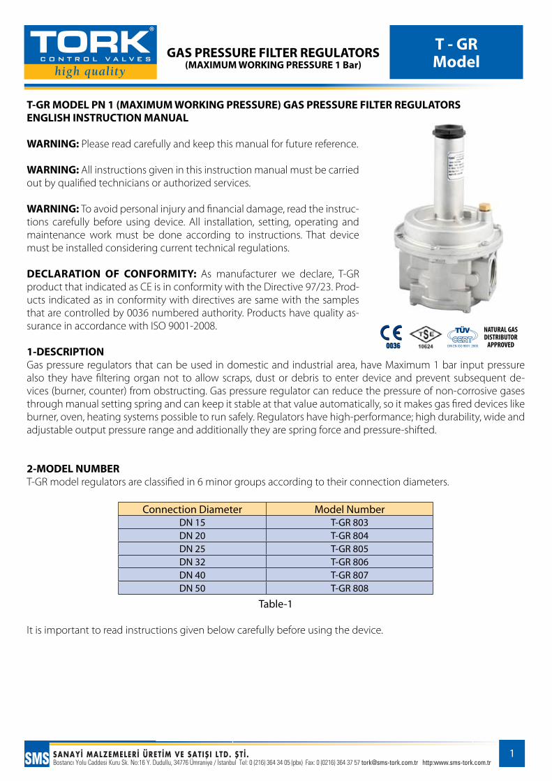
1-DESCRIPTIONGas pressure regulators that can be used in domestic and industrial area, have Maximum 1 bar input pressure also they have filtering organ not to allow scraps, dust or debris to enter device and prevent subsequent de-vices (burner, counter) from obstructing. Gas pressure regulator can reduce the pressure of non-corrosive gases through manual setting spring and can keep it stable at that value automatically, so it makes gas fired devices like burner, oven, heating systems possible to run safely. Regulators have high-performance; high durability, wide and adjustable output pressure range and additionally they are spring force and pressure-shifted.
2-MODEL NUMBER T-GR model regulators are classified in 6 minor groups according to their connection diameters.
Connection Diameter Model NumberDN 15 T-GR 803DN 20 T-GR 804DN 25 T-GR 805DN 32 T-GR 806DN 40 T-GR 807DN 50 T-GR 808
Table-1
It is important to read instructions given below carefully before using the device.
NATURAL GAS DISTRIBUTOR
APPROVED
GAS PRESSURE FILTER REGULATORS(MAXIMUM WORKING PRESSURE 1 Bar)
T - GRModel
2
3- WORKING PRINCIPLE-AREA OF USAGE-GENERAL DESCRIPTION-TECHNICAL DATA AND PROPERTIEST-GR regulators are devices that can reduce the line pressure and keep it stable on that value through screw or unscrew (preferable) the setting spring at the upper cap part manually.Maximum working pressure of the regulator is 1 bar and they have a safety diaphragm to disrupt gas flow in case of the main diaphragm is torn.
Usage area: Mains and industrial usage Fluid type: Natural gas, lpg, methane, propane, butane, town gas, air, non-corrosive gases (number 3 gas group) Environment temperature: -150C; 600CMax. Superficial temperature: 600CMax. Input and Working pressure: 1 barOutput Pressure Setting Range: 10-500 mbar (Outlet pressure can be changed or adjusted by using springs in Table-2.) Threaded connections: DN 15, DN 20, DN 25, DN 32, DN 40, DN 50 Connections Threaded ConnectionFiltration and filtration class: 20 micron – G2 (In case of need different pore diameters)Materials: Aluminum body and cap, rustproof, knitted, washable, removable synthetic fiber filter, O-rings and seals that provide gas-tightness are resistant to number 3 gas group H-NBR.
Device, Material and Documentation Norms:Aluminum and Aluminum Alloys: TS EN 1706, TS EN 2349, TS 573-3Brass and Copper Alloys: TS EN 12449, TS EN 12164Stainless Steels: TS EN 10088Filter: TS EN 779Springs: TS 1440Seal, diaphragm and O-rings (NBR Rubber) :TS EN 13787, TS 10909 EN 549, TS 9808, TS 3563Threaded connections: ISO 7/1, TS 61-210 EN 10226Nylon materials: EN 11667Documentation Norms: Our products conform to the 97/23/EC Directive ,EN 88 and TS 10624 standards.

GAS PRESSURE FILTER REGULATORS(MAXIMUM WORKING PRESSURE 1 Bar)
T - GRModel
3
Figure 1- T-GR Model DN15-DN 20-DN25 (Connection) TORK Gas Filter Regulator Product Tree
Pos. No. Name of Part Unit
1 Body 12 Flange 13 Funnel 14 Bottom Cap 15 Outer Diaphragm 16 Inner Diaphragm 17 Compensation Diaphragm 18 Bottom Cap Seal 19 Flange O-Ring 1
10 Central Pin Seal 111 Tap O-Ring 112 Flange Seal O-Ring 413 Diaphragm Upper Disc 114 Diaphragm Lower Disc 115 Central Pin Set Screw 116 Central Pin Set Screw Nut 117 Central Pin Set Screw Washer 1
Pos. No. Name of Part Unit
18 Central Pin 119 Filter 120 Compensation Diaphragm 121 Spring Regulation Screw 122 Spring Washer 123 Spring 124 Tap 125 Blowback Tube 126 Anti Dust Tube 127 Flange 428 Bottom Cap Seals 629 Compensation Diaphragm Screw Seals 430 Compensation Diaphragm Screw Ring 131 Funnel Screw Seals 632 Blowback Tube O-Ring 133 Diaphragm Lower Disc O-Ring 1

GAS PRESSURE FILTER REGULATORS(MAXIMUM WORKING PRESSURE 1 Bar)
T - GRModel
4
Figure-2 T-GR Model DN 32-DN40-DN50 (Connection) TORK Gas Filter Regulator Product Tree
Pos. No. Name Of Part Unit1 Body 12 Flange 13 Funnel 14 Bottom Cap 15 Outer Diaphragm 16 Inner Diaphragm 17 Diaphragm Upper Disc 18 Diaphragm Lower Disc 19 Central Pin Shaft Nut 1
10 Central Pin Shaft Washer 111 Central Pin Bearing 112 Compensation Diaphragm Carrier 113 Central Pin 114 Central Pin Seal 115 Central Pin Seal Screw Washer 116 Central Pin Shaft O-ring 1
Pos. No. Name Of Part Unit17 Central Pin Shaft 118 Bottom Cap Seal 119 Sensor Tube 120 Flange Screw O-Ring 621 Flange O-Ring 122 Compensation Diaphragm 123 Funnel Fixing Screws 824 Flange Screws 625 Bottom Cap Screws 626 Anti Dust Tube 127 Tap 128 Tap O-Ring 129 Regulation Screw 130 Washer For Spring 131 Setting Spring 132 Filter 1
GAS PRESSURE FILTER REGULATORS(MAXIMUM WORKING PRESSURE 1 Bar)
T - GRModel
5
Regulator is designed to be installed front of settings organs to control pressure of the gas lines.
Tork regulators are in conformity with the Directive 94/9/CE as device of group II and category 3G and 3D.Device group II –category 3 includes the devices designed to supply protection in normal standards. Device group of II and category 3 is suitable to be used in areas which has a low potentiality of originate explosive atmosphere or might originate explosive atmosphere for very short time. It is suitable to be installed in the zones 1 and 21 besides in the zones 2 and 22.The regulator is not suitable to be used in zones 0 and 20 as classified in the Directive 99/92/EC.
Regulator can be dangerous for the other devices close to it as a result of damage either of the working diaphragm or of the safety one, only in this case regulator is a source of emission of gas and it can originate dangerous areas 0 as defined in the 99/92/EC Directive.
Outside the regulator, at downstream of it, there is checking pressures tap for the control of the regulation pres-sure.
The device, if installed, serviced and maintained regarding all the conditions and technical instructions in this document, is not a source of danger. Particularly, during the normal working, it is only infrequent to cause an inflammable atmosphere.
To determine the dangerous zones, see the norm EN60079-10.
Filtering organ is made of washable and removable synthetic material and seal for gas-tight is made of NBR mate-rial.
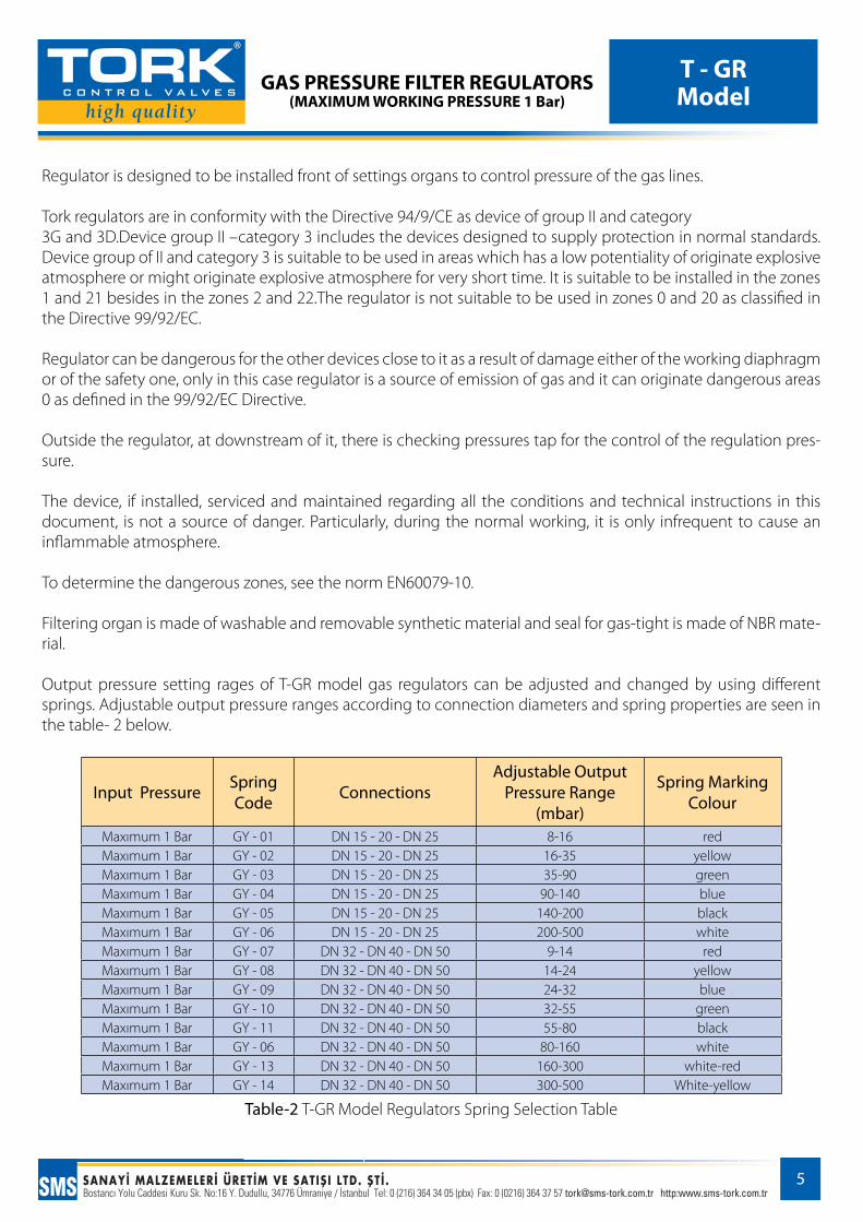
Output pressure setting rages of T-GR model gas regulators can be adjusted and changed by using different springs. Adjustable output pressure ranges according to connection diameters and spring properties are seen in the table- 2 below.
Input Pressure Spring Code Connections
Adjustable Output Pressure Range
(mbar)
Spring Marking Colour
Maxımum 1 Bar GY - 01 DN 15 - 20 - DN 25 8-16 redMaxımum 1 Bar GY - 02 DN 15 - 20 - DN 25 16-35 yellowMaxımum 1 Bar GY - 03 DN 15 - 20 - DN 25 35-90 greenMaxımum 1 Bar GY - 04 DN 15 - 20 - DN 25 90-140 blueMaxımum 1 Bar GY - 05 DN 15 - 20 - DN 25 140-200 blackMaxımum 1 Bar GY - 06 DN 15 - 20 - DN 25 200-500 whiteMaxımum 1 Bar GY - 07 DN 32 - DN 40 - DN 50 9-14 redMaxımum 1 Bar GY - 08 DN 32 - DN 40 - DN 50 14-24 yellowMaxımum 1 Bar GY - 09 DN 32 - DN 40 - DN 50 24-32 blueMaxımum 1 Bar GY - 10 DN 32 - DN 40 - DN 50 32-55 greenMaxımum 1 Bar GY - 11 DN 32 - DN 40 - DN 50 55-80 blackMaxımum 1 Bar GY - 06 DN 32 - DN 40 - DN 50 80-160 whiteMaxımum 1 Bar GY - 13 DN 32 - DN 40 - DN 50 160-300 white-redMaxımum 1 Bar GY - 14 DN 32 - DN 40 - DN 50 300-500 White-yellow
Table-2 T-GR Model Regulators Spring Selection Table
GAS PRESSURE FILTER REGULATORS(MAXIMUM WORKING PRESSURE 1 Bar)
T - GRModel
6
4-INSTILATIONAll installation work must be carried out by skilled technician. Installation should not be done by user absolutely.
Regulator is normally installed before the user. It must be installed with the arrow on the body towards the user, so flow direction is from mains to the user. Connect the product to the male thread through screwing and check gas-tightness. Regulator can be installed in any direction but it is preferable to install with the spring vertically. (It is not recommended to install with the regulator cap downwardly.) Regulator is suitable for installation to horizontal pipes. If it is needful to install to vertical pipes, prefer vertical pipes which flow direction is from top to bottom. Output pressure of the regulator can be checked by the test nipple in the output direction. Every regulator must be installed suitable for calibration in place.It is recommended to use filter in every facility.Remove plastic strainers of the output and input of the regulator, before installation. Every facility must be cleaned by air before installation.Dimensional measures of product and line compatibility must be checked before installation.The pipes must be cleaned and aligned before installation.Check that if there is any setover in the line before installation. The gas supply must be shut off before installation. Be sure that pressurized gas is not present in the line and the emission of gas is blocked over the installation Also make sure the controlling valve of the gas flow is off.Before the installation, installation area must be checked if there are potential sources or dangerous devices close the regulator that is suspicious to originate electric arc or sparks.The line must be checked if there are particles, scraps exc. before installation.Vents for unloading the active line must be allocated before installation.Inert gas must be applied to the natural gas system before the cutting and welding processes are startedDuring installation take care not to allow metal pieces, swarf or seals to enter the device.During installation product must not be overloaded or impacted. Install without mechanical stress.Use seal materials that are allowed to use in installation.Install by using appropriate tool without applying hand force to body or cap.Check that regulator is assembled not reverse after installation.Always check that system is gas-tight after installation.
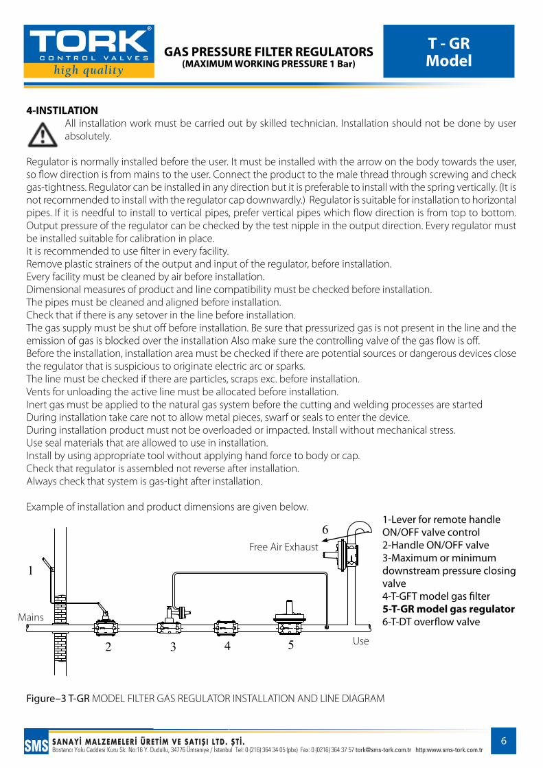
Example of installation and product dimensions are given below.1-Lever for remote handle ON/OFF valve control 2-Handle ON/OFF valve 3-Maximum or minimum downstream pressure closing valve 4-T-GFT model gas filter5-T-GR model gas regulator6-T-DT overflow valve
Figure–3 T-GR MODEL FILTER GAS REGULATOR INSTALLATION AND LINE DIAGRAM
Mains
Free Air Exhaust
Use
GAS PRESSURE FILTER REGULATORS(MAXIMUM WORKING PRESSURE 1 Bar)
T - GRModel
7
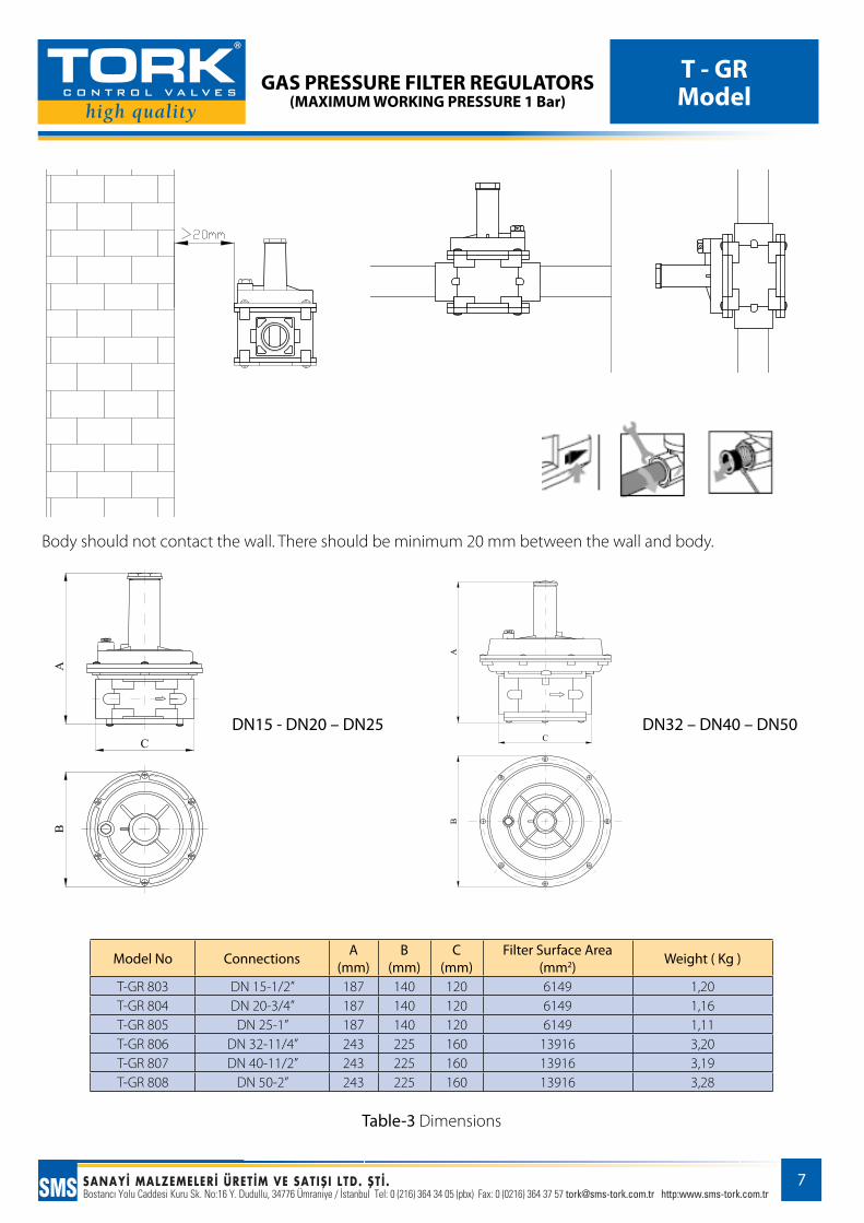
Body should not contact the wall. There should be minimum 20 mm between the wall and body.
DN15 - DN20 – DN25 DN32 – DN40 – DN50
Model No Connections A(mm)
B(mm)
C(mm)
Filter Surface Area (mm2) Weight ( Kg )
T-GR 803 DN 15-1/2” 187 140 120 6149 1,20T-GR 804 DN 20-3/4” 187 140 120 6149 1,16T-GR 805 DN 25-1” 187 140 120 6149 1,11T-GR 806 DN 32-11/4” 243 225 160 13916 3,20T-GR 807 DN 40-11/2” 243 225 160 13916 3,19T-GR 808 DN 50-2” 243 225 160 13916 3,28
Table-3 Dimensions
GAS PRESSURE FILTER REGULATORS(MAXIMUM WORKING PRESSURE 1 Bar)
T - GRModel
8
5- CALIBRATION- THE CHOICE OF THE REGULATOR –FLOW RATE CONVERSION –CHANGEOVER OF OUT-PUT PRESSURE AND SPRING
Calibration: Before starting the system, pay attention that the regulation spring can supply the needed regulation pressure. To supply pressure to the regulator ,open input valve (Figure3-number 2) slowly and gradually. (Do not open the input valve instantly.) After removing the plastic tap, calibrate the regulator at the minimum and turn the adjusting screw slowly clockwise and calibrate the output pressure up to the needed pressure. Output pressure of the regulator can be checked by the test nipple in the output direction.
The Choice of the Regulator: The choice of regulator is very important. First of all you need to know: the avail-able input pressure in the line, needed output pressure and needed flow rates . Model supplies the needed flow rate should be chosen from Table-4 given below. Than spring supplies the needed output pressure for the specified model should be chosen from Table-2 and the choice process ends.
Suitable output pressure range is determined by different spring selections.
It is recommended that the flux speed mustn’t exceed 30m/s.For better regulation in high flux speeds, choose next diameter. An ideal regulator should be chosen considering 10% deflection.You must choose the smallest regulator assuring the necessary flow rate at related pressures.
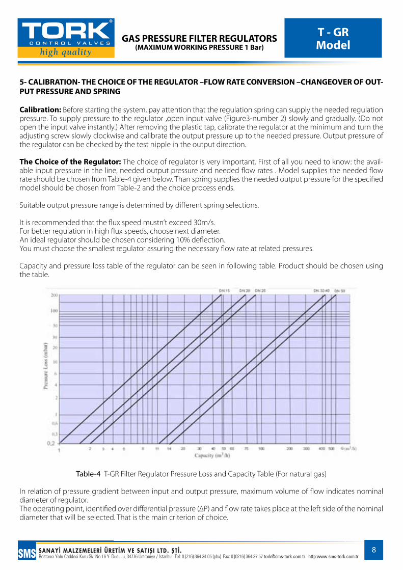
Capacity and pressure loss table of the regulator can be seen in following table. Product should be chosen using the table.
Table-4 T-GR Filter Regulator Pressure Loss and Capacity Table (For natural gas)
In relation of pressure gradient between input and output pressure, maximum volume of flow indicates nominal diameter of regulator.The operating point, identified over differential pressure (∆P) and flow rate takes place at the left side of the nominal diameter that will be selected. That is the main criterion of choice.

GAS PRESSURE FILTER REGULATORS(MAXIMUM WORKING PRESSURE 1 Bar)
T - GRModel
9
Example of Regulator Choice:Input pressure: P1: 50 mbarNeeded output pressure: P2: 20 mbarNecessary output flow rate: Q: 20 m3/h
Regarding the values given below; ∆P1:50-20:30 mbar
In Table-5 Draw a vertical line from the required flow rate point (20 m3/h) to the up and define the points that verti-cal line intersects the curves. Than draw horizontal lines from defined points to the left and specify pressure losses for various models.
The regulator which includes the closest curve to 30 mbar should be chosen because it is the smallest regulator assures necessary flow rate. (Eventually the smallest regulator that makes real the condition, needed ∆P > regulator ∆P, should be chosen.)
As it is seen in the Table-5, while P1, P2, P3 and P4 points are lower than 30 mbar, P5 is higher than 30 mbar, so P5 should be out of choice. P4 should be chosen because it is the closest point to 30 mbar; therefore it is the smallest regulator that can assure the needed pressure.
As it is seen in the Table-5 given below, T-GR 804 is the ideal model assuring needed flow rate, in consideration of having the closest pressure loss to 30 mbar (approximately 18 mbar)
After the choice of model, it is necessary to determine the suitable spring assures the needed output pressure 20 mbar for that model. Table -2 indicates that GY-02 is ideal spring for T-GR 804 and choice of regulator is completed.
NOTE: Besides Maximum flow rate in case ∆P is 30 mbar can be analyzed in terms of input and output pressure. Draw a horizontal line from 30 mbar point to the right and draw a vertical line from the point that horizontal line intersects the curve of chosen regulator model to downward. End of the vertical line indicates the Maximum flow rate that chosen regulator can have as ∆P is 30 mbar. As it is seen, Maximum flow rate is 28 m3/h for chosen regulator. Minimum flow rate is ten percent of Maximum flow rate, that is to say 28 x 0,1 : 2,8 m3/h .
Table-5 T-GR Example Choice Table
GAS PRESSURE FILTER REGULATORS(MAXIMUM WORKING PRESSURE 1 Bar)
T - GRModel
10
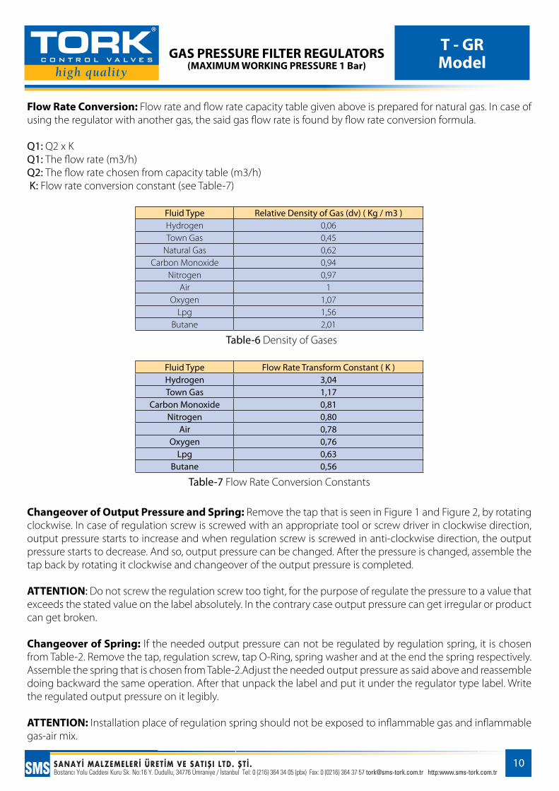
Flow Rate Conversion: Flow rate and flow rate capacity table given above is prepared for natural gas. In case of using the regulator with another gas, the said gas flow rate is found by flow rate conversion formula.
Q1: Q2 x KQ1: The flow rate (m3/h)Q2: The flow rate chosen from capacity table (m3/h) K: Flow rate conversion constant (see Table-7)
Fluid Type Relative Density of Gas (dv) ( Kg / m3 )Hydrogen 0,06Town Gas 0,45
Natural Gas 0,62Carbon Monoxide 0,94
Nitrogen 0,97Air 1
Oxygen 1,07Lpg 1,56
Butane 2,01
Table-6 Density of Gases
Fluid Type Flow Rate Transform Constant ( K )Hydrogen 3,04Town Gas 1,17
Carbon Monoxide 0,81Nitrogen 0,80
Air 0,78Oxygen 0,76
Lpg 0,63Butane 0,56
Table-7 Flow Rate Conversion Constants
Changeover of Output Pressure and Spring: Remove the tap that is seen in Figure 1 and Figure 2, by rotating clockwise. In case of regulation screw is screwed with an appropriate tool or screw driver in clockwise direction, output pressure starts to increase and when regulation screw is screwed in anti-clockwise direction, the output pressure starts to decrease. And so, output pressure can be changed. After the pressure is changed, assemble the tap back by rotating it clockwise and changeover of the output pressure is completed.
ATTENTION: Do not screw the regulation screw too tight, for the purpose of regulate the pressure to a value that exceeds the stated value on the label absolutely. In the contrary case output pressure can get irregular or product can get broken.
Changeover of Spring: If the needed output pressure can not be regulated by regulation spring, it is chosen from Table-2. Remove the tap, regulation screw, tap O-Ring, spring washer and at the end the spring respectively. Assemble the spring that is chosen from Table-2.Adjust the needed output pressure as said above and reassemble doing backward the same operation. After that unpack the label and put it under the regulator type label. Write the regulated output pressure on it legibly.
ATTENTION: Installation place of regulation spring should not be exposed to inflammable gas and inflammable gas-air mix.
GAS PRESSURE FILTER REGULATORS(MAXIMUM WORKING PRESSURE 1 Bar)
T - GRModel
11
6- MAINTENANCE -REPAIRAll maintenance, repair and cleaning work given below must be carried out qualified technicians. End users should not attempt to do maintenance, repair or cleaning work by themselves certainly. User or unqualified persons should not interfere in the event of any maintenance, repair or malfunction
User is responsible to get product serviced and maintained periodically and make sure that it is working regularly. (It is recommended that not to be longer than 1 year.) According to utilization conditions, device can be removed from the line for cleaning or maintenance work.
Before disassembling the device for maintenance or repair make sure that there is no pressured gas inside and this condition is secured to continue until the process is completed. Make sure overflow valve is off.
To check or substitute diaphragms; unscrew the funnel seal and remove the funnel; take off outer diaphragm; un-screw the central nut that fixes the working diaphragm. Reassemble doing backward the same operation, paying attention when tightening the nut not to turn diaphragms, stop the disc on the diaphragm with free hand.
To check the filtering organ on threaded body; unscrew the bottom cap seals and remove the bottom cover. Remove the filtering organ and clean it with soap and water, blow it with compressed air or substitute if it is nec-essary. Reassemble it in its original position. Reassemble the bottom being sure that central pin is in centered in the bottom hole.
Reassemble the device doing backward the same operation and complete maintenance work. Install the device back to its place regarding the instructions.
Before reinstall the regulator back to the line, use suitable gas-tightness components (Teflon band) absolutely. Check that the system is gas-tight after reinstallation, if it is necessary use soap suds. The method given below can be used for that.Close input and output pipeline. Feed pressure to the regulator slowly. It should be; input pressure ≤ 1,5x Maxi-mum Input Pressure and Output Pressure ≤ 1,5x Maximum Output Pressure (see Table-2) Apply input pressure firstly and then apply output pressure.
ATTENTION: That order should be followed definitely; otherwise regulator can be broken down. In that method it is seen input pressure is bigger or equal to output pressure definitely. Afterwards bleed off out-put pressure initially and then bleed off input pressure.
ATTENTION: That order should be followed definitely otherwise regulator can be broken down.
In condition of the fluid flows through regulator is biogas, maintenance and function check should be done every six months.
In case of necessity, replacement parts like springs, diaphragms, O-Rings, filters etc. can be supplied from by our company. If the device falls out of use, contact our company to buy a new one.
For detailed technical information and any questions about replacement parts, authorized service and mainte-nance contact us.
.

GAS PRESSURE FILTER REGULATORS(MAXIMUM WORKING PRESSURE 1 Bar)
T - GRModel
12
7- POINTS TO CONSIDER AND WARNINGSFor all gas lines, it is advised to use our product in order to avoid arguments of the system from damage.In conditions of particularly critic installation ( places not protected, lack of ventilation, lack of servicing) or espe-cially in presence ,close to the regulator, of potential sources of dangerous devices or inflammable materials dur-ing the normal working because suspicious to originate electric arcs or sparks, it is necessary to value the compat-ibility between the regulator and these devices before installation. In such cases the regulator can be dangerous as regards to the presence of potential initiator. In any case it is necessary to take any useful precaution to avoid that could be origin of areas 0: (For example yearly periodical inspection of regular working, possibility to change emission degree of source or to attend on exhaust outside explosive material can be assured. To do so it is pos-sible, to connect outside by a copper pipeline the threaded hole 1/4” (union) removing the brass anti dust cap)
Check that if product is damaged or lacking in necessary parts before installation. If any of these cases is seen, the delivery should be refused.Before using the device, check the product label and the other information on the box.Check that the line pressure does not exceed the Maximum pressure stated on the label before installation.Before installation, check the compatibility between the device and system.Working limits given in technical instructions should not be exceeded and do not pressurize the product more than maximum pressure.The arrow on the body of regulator must be towards the end user before installation.Be sure there is no gas inside the line and prevent any possibility to change that condition during installation.Before installation, suitable stuffing content (Teflon band, external taper union etc.) should be used to provide gas-tightness and be sure system is gas-tight.As analyzing the efficiency of device, be sure there is no gas leak from the connection point.Be sure that device is installed to the line correctly and connections are right too.Regulator should be installed regarding usage direction. Check that if the device is installed reverse.Do not install the regulator to vertical pipes unless it is necessary. In case of need, choose flows that go from top to bottom.Install every armature regarding it will be removed for maintenance.Use union, manometer or ball valve with the input and output of the regulator, because of disassembling possibil-ity for maintenance. Also do not pump test air via outlet of regulator. Calibrate the device.If the device threaded check that pipeline thread is not too long, over long threads may damage the body of device when screwed into place.Regulation valves that can be fixed with the output and input of the regulator if required, should be turn on and off slowly. Regulation valves are not combined systems with regulator, it is recommended to be used. Tool during assembly and disassembly and carry out the process using connections.Do not carry out welding or cutting unless inert gas is exerted on the gas facility.As analyzing the efficiency of device, be sure device is connected to the line tightly and there is no gas leak.Do not come close to the regulator with inflammable and electrical materials.Do not pump test air via outlet of regulator.If you smell a gas leak, shut off the main input valve of regulator and contact authorized service. Meantime venti-late the atmosphere.If it is necessary to disassemble the regulator from line for any reason, be sure that the pressure is shutdown.
ATTENTION: The packaged label in the regulator box is to write and stick the adjusted output pressure on the regulator.
GAS PRESSURE FILTER REGULATORS(MAXIMUM WORKING PRESSURE 1 Bar)
T - GRModel
13
8- MISUSAGES AND MALFUNCTIONSIf you experience any of malfunctions similar to given above, do not interfere and contact authorized service or our company.
If the line pressure exceeds the Maximum pressure stated in technical information, device could be broken down as a result of that high and uncontrollable pressure occurs at downstream of the regulator continuously.In the event that filter organ of the regulator is obstructed because of the dust carried over from the line, that defect causes to reduce the flow rate of the gas. In such a case, you should contact us for maintenance.If you suspect that there is a gas leak on the line, regulator is installed, contact us or authorized service urgently. (In such case, it can be realized from rising of output pressure even though regulation spring is stable or smell of gas in the atmosphere.)If output pressure of the regulator rises permanently, it indicates that there is a malfunction about diaphragm system and the device is defected. The regulator is defected if it makes noise or clutter.As the regulator works under normal operating conditions perfectly at the line and user side, in case it does not supply the needed pressure value and can not regulate the pressure or it does not give any pressure, the device is defected.If output pressure can not be regulated, device is broken down.If regulator exceeds the output pressure that it is stated on its label, device is broken down. In such condition, regulation screw should be unscrewed in anti-clockwise direction. If it continues, spring should be removed and fix again. After all this if pressure still exceeds, device is broken down. In a condition of the device makes measuring error, browse installation instruction and check that if installation is done correctly.
9- SHIPPING-DELIVERyAll of our products are packaged with special carton boxes to avoid any damages during delivery and shipping. Products should not be thrown, loaded too much weight on it, convulsed or put on wet surfaces. Our company takes responsibility for damages that occurs during shipping and delivery. 10- WARRANTy TERMS AND CONDITIONS1- The warranty period is two years from date of delivery for processing errors.2- The repairing period is maximum 30 working day.3-Any defect that arises due to faulty materials or workmanship will be repaired free of charge within the warranty period.4-Warranty does not cover damages because of not following the instructions in the manual. (Installing poorly, exceeding the limits given in technical instructions, misusage, neglecting etc.)5-User is responsible to arrange compatibility between the system and product also to make conditions appropri-ate for installation. Our company disclaims any liability for defects because of said conditions.6--Service and replacement parts are under warranty of our company.7-Product life time stated by Ministry of Industry and Commerce is 10 years.( Product should not be used out of the conditions given in the instruction manual. User is responsible for any defect that arises due to misuse.)8- Product should not be used out of the conditions given in the instruction manual. User is responsible for any defect that arises due to misuse.)
GAS PRESSURE FILTER REGULATORS(MAXIMUM WORKING PRESSURE 1 Bar)
T - GRModel
14
GAS PRESSURE FILTER REGULATORS(MAXIMUM WORKING PRESSURE 1 Bar)
T - GRModel
15
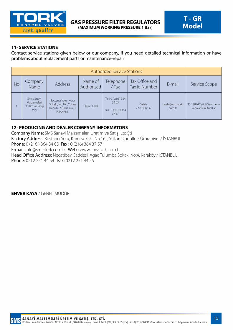
11- SERVICE STATIONS Contact service stations given below or our company, if you need detailed technical information or have problems about replacement parts or maintenance-repair
Authorized Service Stations
NoCompany
NameAddress
Name of Authorized
Telephone / Fax
Tax Office and Tax Id Number
E-mail Service Scope
1
Sms Sanayi Malzemeleri
Üretim ve Satışı Ltd.Şti
Bostancı Yolu , Kuru Sokak , No:16 , Yukarı Dudullu / Ümraniye /
İSTANBUL
Hasan CEBİ
Tel : 0 ( 216 ) 364 34 05
Fax : 0 ( 216 ) 364 37 57
Galata7720358339
TS 12844 Yetkili Servisler – Vanalar İçin Kurallar
12- PRODUCING AND DEALER COMPANy INFORMATONSCompany Name: SMS Sanayi Malzemeleri Üretim ve Satışı Ltd.ŞtiFactory Address: Bostancı Yolu, Kuru Sokak , No:16 , Yukarı Dudullu / Ümraniye / İSTANBUL Phone: 0 (216 ) 364 34 05 Fax : 0 (216) 364 37 57E-mail: [email protected] Web : www.sms-tork.com.trHead Office Address: Necatibey Caddesi, Ağaç Tulumba Sokak, No:4, Karaköy / İSTANBULPhone: 0212 251 44 54 Fax: 0212 251 44 55
ENVER KAyA / GENEL MÜDÜR