
GAS OPERATED BOILERS INSTALLATION - OPERATION - MAINTENANCE · GAS OPERATED BOILERS INSTALLATION -...
12
MG SERIES GAS OPERATED BOILERS INSTALLATION - OPERATION - MAINTENANCE Telephone: (802) 658-6600 Fax: (802)864-0183 www.marketforge.com PN 14-0307 Rev F (11/17) © 2017 - Market Forge MODELS M24G M36G
Transcript of GAS OPERATED BOILERS INSTALLATION - OPERATION - MAINTENANCE · GAS OPERATED BOILERS INSTALLATION -...

MG SERIESGAS OPERATED BOILERS
INSTALLATION - OPERATION - MAINTENANCE
Telephone: (802) 658-6600 Fax: (802)864-0183www.marketforge.com PN 14-0307 Rev F (11/17)
© 2017 - Market Forge
MODELS
�M24G �M36G
Your Service Agency’s Address:Model
Serial number
Boiler installed by
Installation checked by

TABLE OF CONTENTS
INSTALLATIONIntroduction . . . . . . . . . . . . . . . . . . . . . . . . . . . . . . . . . . . . . . . . . . . . . . . . . . . . . . . . . . . . . . 2Service Connections . . . . . . . . . . . . . . . . . . . . . . . . . . . . . . . . . . . . . . . . . . . . . . . . . . . . . 4
OPERATIONControl Panel . . . . . . . . . . . . . . . . . . . . . . . . . . . . . . . . . . . . . . . . . . . . . . . . . . . . . . . . . . . . 6
MAINTENANCECleaning the Boiler . . . . . . . . . . . . . . . . . . . . . . . . . . . . . . . . . . . . . . . . . . . . . . . . . . . . . . . 7
IMPORTANT WARNING: Improper installa-tion, adjustment, alternation, service or maintenance can cause property damage, in-jury or death. Read the instal-lation, operation and mainte-nance instructions thoroughly before installing or servicing this equipment.
INSTRUCTIONS TO BE FOL-LOWED IN THE EVENT THE USER SMELLS GAS MUST BE POSTED IN A PROMINENT LO-CATION. This information may be obtained by contacting your local gas supplier.
FOR YOUR SAFETY
Do not store or use gasoline or other flammable vapors or liq-uids in the vicinity of this or any other appliance.
The information contained in this manual is important for the prop-er installation, use, and mainte-nance of this boiler. Adherence to these procedures and instruc-tions will result in satisfactory baking results and long, trou-ble free service. Please read this manual carefully and retain it for future reference.
ERRORS: Descriptive, typo-graphic or pictorial errors are subject to correction. Specifi-cations are subject to change without notice.

2INSTALLATION
Introduction
TO THE KITCHEN MANAGER:1. Read this manual carefully and in its entirety. Contact
Market Forge for clarification if necessary.
2. Protect your kitchen personnel from scalding and other serious injury by providing training programs to acquaint all equipment operators with the correct and safe methods of operation.
3. Operators must be made aware of the consequences of misuse. Steam producing equipment, no matter who the manufacturer, is inherently dangerous when misused. The possibility of serious scalding always exists; the careless and/or untrained operator will be injured.
4. This equipment must be maintained according to the guidelines in this manual (see “maintenance”). Lack of maintenance will lead to a potentially hazardous condition and possible liability. Operators should re-port any equipment malfunction immediately and steps must be taken to correct the problem before further use of the equipment is allowed.
5. Keep this manual for daily reference.
Market Forge, in the interest of both cost and efficiency has designed these steam boilers with the latest auto-matic controls in order to make it easier for the operator to use and maintain this equipment. Standard compo-nents are utilized on all models unless variances in size or capacity dictate a divergence from this policy for more efficiency of operation. This parts and service manual is written and illustrated to cover all steam boiler equipment that uses gas as a source of fuel other than those which have been custom designed under special order.
THEORY OF OPERATION FOR GAS BOILERAn explanation of how the control system operates on au-tomatic gas boilers follows:After the boiler is filled with water to the proper level and the fuel switch is turned ON, the main gas valve will be activated allowing gas to flow to the main burners that will be ignited by the Spark Pilot. When the boiler builds to its set pressure, the pressure switch opens. This will open the circuit to the gas valve that will stop the flow of gas to the main burners. As the pressure in the boiler drops the pressure control switch will again complete the circuit and build the boiler back to its set pressure. To stop all steam generation place the FILL/ON-OFF switch to the OFF position.
CAUTIONBe sure to read.
• Keep this appliance area free and clear from com-bustibles.
• Do not obstruct the flow of combustion and ventila-tion air.
• Keep this manual for future reference.
• This installation must conform with local codes, or in the absence of local codes, with the National Fuel Gas code, ANSI Z223.1-Latest Edition. For installa-tion in Canada, this appliance is to be in accordance with the current CAN/CGA-B149 (.1 or .2) Installa-tion Code for Gas Burning Appliances and Equip-ment and/or Local Codes.
• This appliance, when installed, must be electrically grounded in accordance with local codes, or in the absence of local codes, with the National Electric Code, ANSI/NFPA70-Latest Edition. For installation in Canada, All electrical connections are to be made in accordance with CSA C22.1 Canadian Electrical Code Part 1 and/or Local Codes.
• The boiler and its individual shut off valve must be disconnected from the gas supply piping system during any pressure testing of that system at test pressure in excess of 1/2 PSI (0.03 kg/cm2).
• The boiler must be isolated from the gas supply system by closing its individual manual shut off valve during any pressure testing of the gas supply piping system at test pressures equal to or less than 1/2 PSI (0.03 kg/cm2).
• The wiring diagram label is located on the inside of the Lift-Off Front Panel.

3 INSTALLATION
Introduction
• This product must be installed in a room with ad-equate air supply.
• Do not place any objects on or directly against the unit as to block air openings into the combustion chamber.
• Clearances from both combustible and non-combus-tible construction are 3” (76mm) from sidewalls, 6” (152mm) from rear wall. With lower deflector plate, shown below, installed this unit is suitable for instal-lation on combustible floors.
• This unit is serviceable from the front, do not install in such a manner where a service person cannot remove front panels.
INSTALLING LEGSSome models are shipped without legs. A separate carton will contain the legs. If your model is received this way, be sure to follow the installation instruction sheet packed with the legs.
LEVELINGIn order for the boiler to drain correctly, it is important to use a level on cabinet top both left and right and front-to-back. If not level, adjust feet. On compartment cookers, check the interior shelves for level condition.
LOWER DEFLECTOR PLATEThe lower deflector plate must be installed on the boiler as follows:1. Locate lower deflector as shown (A). The rear brack-
ets will slide in openings and allow it to rest in place on frame.
2. Move lower deflector slightly forward to allow front brackets to fit over 8-32 studs protruding out from the upper deflector plate as shown in (B).
3. Secure lower deflector in place as shown in (C). using 8-32 stainless steel wing nuts.
Figure 1
A
C
B
4INSTALLATION
Service Connections
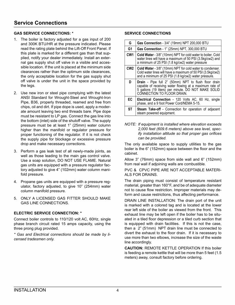
GAS SERVICE CONNECTIONS: *1. The boiler is factory adjusted for a gas input of 200
and 300K BTU/HR at the pressure indicated. Please read the rating plate behind the Lift-Off Front Panel. If this plate is marked for a different gas than that sup-plied, notify your dealer immediately. Install an exter-nal gas supply shut off valve in a visible and acces-sible location. If the unit is placed at the minimum side clearances rather than the optimum side clearances, the only acceptable location for the gas supply shut off valve is under the unit in the space provided by the legs.
2. Use new iron or steel pipe complying with the latest ANSI Standard for Wrought-Steel and Wrought-Iron Pipe, B36, properly threaded, reamed and free from chips, oil and dirt. If pipe dope is used, apply a moder-ate amount leaving two end threads bare. Pipe dope must be resistant to LP gas. Connect the gas line into the bottom (inlet) side of the shutoff valve. The supply pressure must be at least 1” (25mm) water column higher than the manifold or regulator pressure for proper functioning of the regulator. If it is not check the supply pipe for blockage or excessive pressure drop and make necessary corrections.
3. Perform a gas leak test of all newly-made joints, as well as those leading to the main gas control valve. Use a soap solution, DO NOT USE FLAME. Natural gas units are equipped with a pressure regulator fac-tory adjusted to give 4” (102mm) water column mani-fold pressure.
4. Propane gas units are equipped with a pressure reg-ulator, factory adjusted, to give 10” (254mm) water column manifold pressure.
5. ONLY A LICENSED GAS FITTER SHOULD MAKE GAS LINE CONNECTIONS.
ELECTRIC SERVICE CONNECTION: *Connect boiler controls to 110/120 volt AC, 60Hz, single phase branch circuit rated 15 amps capacity, using the three prong plug provided.* Gas and Electrical connections should be made by li-censed tradesmen only.
SERVICE CONNECTIONS
G Gas Connection - 3/4” (19mm) NPT 200,000 BTUG1 Gas Connection - 1” (25mm) NPT, 300,000 BTU
CW1 Cold Water - 3/8” (10mm) NPT for cold water to boiler. Cold water lines will have a maximum of 50 PSI (3.5kg/cw2) and a minimum of 25 PSI (1.8 kg/cw2) water pressure
CW2 Cold Water - 3/8” (10mm) NPT for cold water to condenser. Cold water lines will have a maximum of 50 PSI (3.5kg/cw2) and a minimum of 25 PSI (1.8 kg/cw2) water pressure.
D Drain - Pipe full 2” (50mm) NPT to flush floor drain capable of receiving water flowing at a maximum rate of 5 gallons (19 liters) per minute. DO NOT MAKE SOLID CONNECTION TO FLOOR DRAIN.
EC Electrical Connection - 120 Volts AC, 60 Hz, single phase, and a 9 foot Power Cord/NEMA 5-15.
ST Steam Take-off - Connection for operation of adjacent steam powered equipment.
NOTE: If equipment is installed where elevation exceeds 2,000 feet (609.6 meters) above sea level, spec-ify installation altitude so that proper gas orifices can be provided.
The only available space to supply utilities to the gas boiler is the 6” (152mm) space between the floor and the cabinet. Allow 3” (76mm) space from side wall and 6” (152mm) from real wall if adjoining walls are combustible.PVC & CPVC PIPE ARE NOT ACCEPTABLE MATERI-ALS FOR DRAINS.The drain piping must consist of temperature resistant material, greater than 160°F, and be of adequate diameter not to cause flow restriction. Improper materials may de-form and cause restrictions, thus affecting performance.DRAIN LINE INSTALLATION: The drain port of the unit is marked with a colored tag and is located at the lower rear left side of the boiler as viewed from the front. This exhaust line may be left open if the boiler has to be situ-ated in a tiled floor depression or a tiled curb section that is equipped with drain facilities. If this is not the case, then a 2” (51mm) NPT drain line must be connected to divert the exhaust to the floor drain. If it is necessary to use more than two elbows, increase the size of the waste line accordingly.CAUTION: REMOTE KETTLE OPERATION If this boiler is feeding a remote kettle that will be more than 5 feet (1.5 meters) away, consult factory before ordering.

5 INSTALLATION
DIMENSIONS ARE IN INCHES [MM]
FLUE
24 [610] M24G36 [914] M36G
4[102]2.5 [64]
D
CW1
EC
10.5[267]
CW2
3 [76] 5 [127] 5 [127]2.75 [70]
G G1
ST
33[838]
10.5[267]
12.5[318
EC ST55[1348]
22[559]
8 [203]
CW1
CW2
D G G16 [152]
27[686]
28[711]
Service Connections
WARNING: DO NOT UNDER ANY CIRCUMSTANCE CONNECT THE EXHAUST DRAIN LINE DIRECTLY TO A SEWER LINE.
Figure 2
WATER SUPPLYGood quality water feed is the responsibility of the owner. Water quality must be within the following gen-eral guidelines.
TDS: 40-125 ppm Chlorides: <25 ppmSilica: <13 ppm pH: 7.0 - 8.5Chloramine: <0.2 ppm Chlorine: <0.2 ppmHardness: 35-100 ppmThe best defense against poor water quality is a water treatment system designed to meet your water quality conditions.
6OPERATION
Control Panel
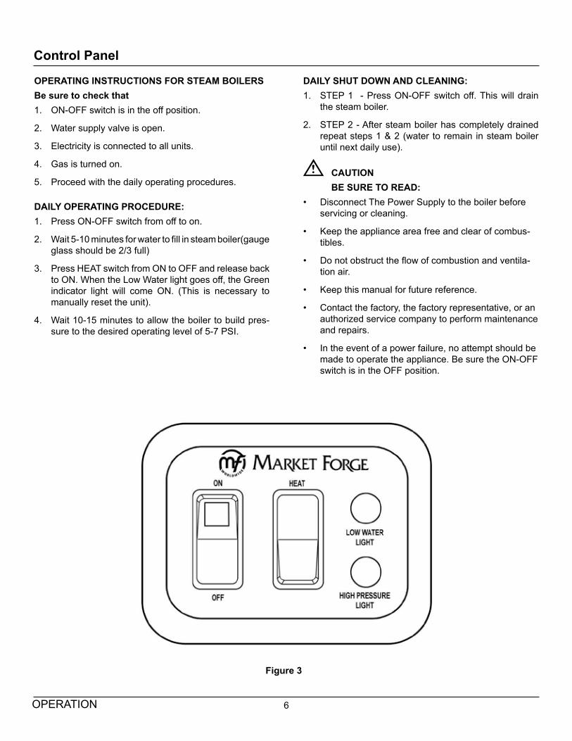
Figure 3
OPERATING INSTRUCTIONS FOR STEAM BOILERSBe sure to check that1. ON-OFF switch is in the off position.
2. Water supply valve is open.
3. Electricity is connected to all units.
4. Gas is turned on.
5. Proceed with the daily operating procedures.
DAILY OPERATING PROCEDURE:1. Press ON-OFF switch from off to on.
2. Wait 5-10 minutes for water to fill in steam boiler(gauge glass should be 2/3 full)
3. Press HEAT switch from ON to OFF and release back to ON. When the Low Water light goes off, the Green indicator light will come ON. (This is necessary to manually reset the unit).
4. Wait 10-15 minutes to allow the boiler to build pres-sure to the desired operating level of 5-7 PSI.
DAILY SHUT DOWN AND CLEANING:1. STEP 1 - Press ON-OFF switch off. This will drain
the steam boiler.
2. STEP 2 - After steam boiler has completely drained repeat steps 1 & 2 (water to remain in steam boiler until next daily use).
CAUTIONBE SURE TO READ:
• Disconnect The Power Supply to the boiler before servicing or cleaning.
• Keep the appliance area free and clear of combus-tibles.
• Do not obstruct the flow of combustion and ventila-tion air.
• Keep this manual for future reference.
• Contact the factory, the factory representative, or an authorized service company to perform maintenance and repairs.
• In the event of a power failure, no attempt should be made to operate the appliance. Be sure the ON-OFF switch is in the OFF position.

7 MAINTENANCE
Cleaning the Boiler
Market Forge recommends that the boiler be cleaned pe-riodically due to impurities introduced through the water supply. All water supplies contain some mineral deposits and impurities; the degree varies with geographic loca-tion. Market Forge is recommending a cleaning sched-ule that will keep your equipment in proper, safe working order where water supplies are relatively pure. Because no water supply can be accurately compared with that of another, this section should not be regarded as fool proof. A stepped-up, more frequent cleaning schedule may be required when excessive impurities exist.The Cleaning schedule should be performed two or more times per year as governed by the local water conditions. Market Forge recommends the use of its “cathodic des-caler” to protect the inner boiler walls and components against rust, scale and lime deposits. The normal ef-fectiveness of a descaler is one year. The schedule for changing the “cathodic descaler” may be timed to the cleaning schedule or accelerated as noted above.Market Forge qualified service agencies are available to establish a suitable schedule for TOTAL CONCEPT cleaning and descaler replacement.REPLACEMENT PARTS NEEDED TO COMPLETE THESE INSTRUCTIONS
PART PART NO.1 Hand-hole Cover Gasket 08-44151 Set of Rubber & Brass Washers 90-00391 Probe Plate Gasket (Gas Only) 08-44131 Market Forge Cathodic Descaler (all boilers) new style
08-0049
1 Dynaseal Washer 10-1135
Cleaning Instructions1. Move the HEAT and POWER switch to their OFF po-
sitions. On electric models also turn off the electric power at the main switch. This will allow the boiler to empty.
WARNING(ALL BOILERS ) DISCONNECT THE 115 VOLT POWER SUPPLY.
2. Remove the hand-hole cover as follows:
a. Remove pressure switch box at the plumbing union and move it out of the way.
b. With an open end wrench back off the hex-nut, counterclockwise, so only two threads are hold-ing it.
c. With a blunt instrument, strike the hand-hole cov-er until its seal is broken.
d. Remove the hex-nut from the remaining two threads, slide off the washer and channel yoke do not allow the hand-hole cover to drop inside.
e. Remove the hand-hole cover by turning it so that it will pass through the opening. Remove the bolt and dynaseal. Discard the hand-hole gasket and dynaseal washer.
Figure 4
3. Clean rust, scale and lime deposits from the inside of the boiler with a wire brush.
WORK DEPOSITS TO CORNER AND REMOVE WITH PUTTY KNIFE.
4. After removing all debris, flush out with clean water through the hand-hole and drain .

8MAINTENANCE
Cleaning the Boiler
5. Clean the hand-hole cover with a wire brush and wash. Be sure the areas that contact the gasket and dynaseal are clean and smooth.
Figure 5
6. To protect against further scale and corrosion remove the old cathodic descaler. Install a New Market Forge Cathodic Descaler.
7. Without the use of gasket compound, re-install the hand hole cover using a new gasket and dynaseal washer. A torque of approximately 50 in. lbs. is re-quired to reset the hex nut. Reinstall the pressure switch box. Bring the boiler to operating pressure. If a leak appears, at the hand hole cover, relieve the pres-sure in the boiler and retighten the hex nut.
8. Clean the water gauge glass as follows:
a. Move the heat and power switch to their off posi-tions. This will allow the boiler to empty.
b. Unscrew the fittings from both valves and slide them toward the center of the gauge glass. Push the water gauge glass downward compressing the rubber washer in the lower valve allowing the glass to be removed.
c. Remove and discard the two rubber and brass washers. Slip off the two valve fittings and clean the water gauge glass.
d. Reassemble by reversing the above steps with new rubber and brass washers (see image be-low).
Figure 6
Weekly CleaningIn addition to the daily cleaning it is necessary to clean the air intakes on a weekly basis. Air intakes provide nec-essary cooling air to the internal components. They are generally located on the rear and sides of the equipment.
9 MAINTENANCE
Cleaning the Boiler
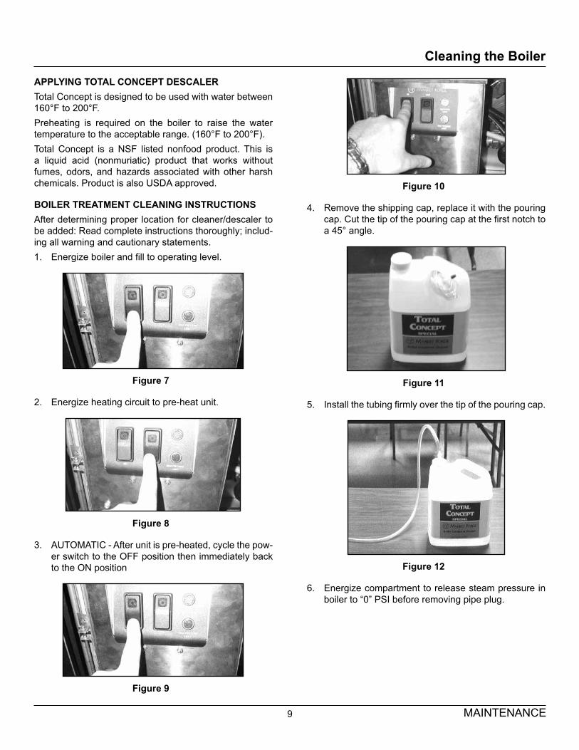
APPLYING TOTAL CONCEPT DESCALERTotal Concept is designed to be used with water between 160°F to 200°F.Preheating is required on the boiler to raise the water temperature to the acceptable range. (160°F to 200°F).Total Concept is a NSF listed nonfood product. This is a liquid acid (nonmuriatic) product that works without fumes, odors, and hazards associated with other harsh chemicals. Product is also USDA approved.
BOILER TREATMENT CLEANING INSTRUCTIONSAfter determining proper location for cleaner/descaler to be added: Read complete instructions thoroughly; includ-ing all warning and cautionary statements.1. Energize boiler and fill to operating level.
Figure 7
2. Energize heating circuit to pre-heat unit.
Figure 8
3. AUTOMATIC - After unit is pre-heated, cycle the pow-er switch to the OFF position then immediately back to the ON position
Figure 9
Figure 10
4. Remove the shipping cap, replace it with the pouring cap. Cut the tip of the pouring cap at the first notch to a 45° angle.
Figure 11
5. Install the tubing firmly over the tip of the pouring cap.
Figure 12
6. Energize compartment to release steam pressure in boiler to “0” PSI before removing pipe plug.
10MAINTENANCE
Cleaning the Boiler
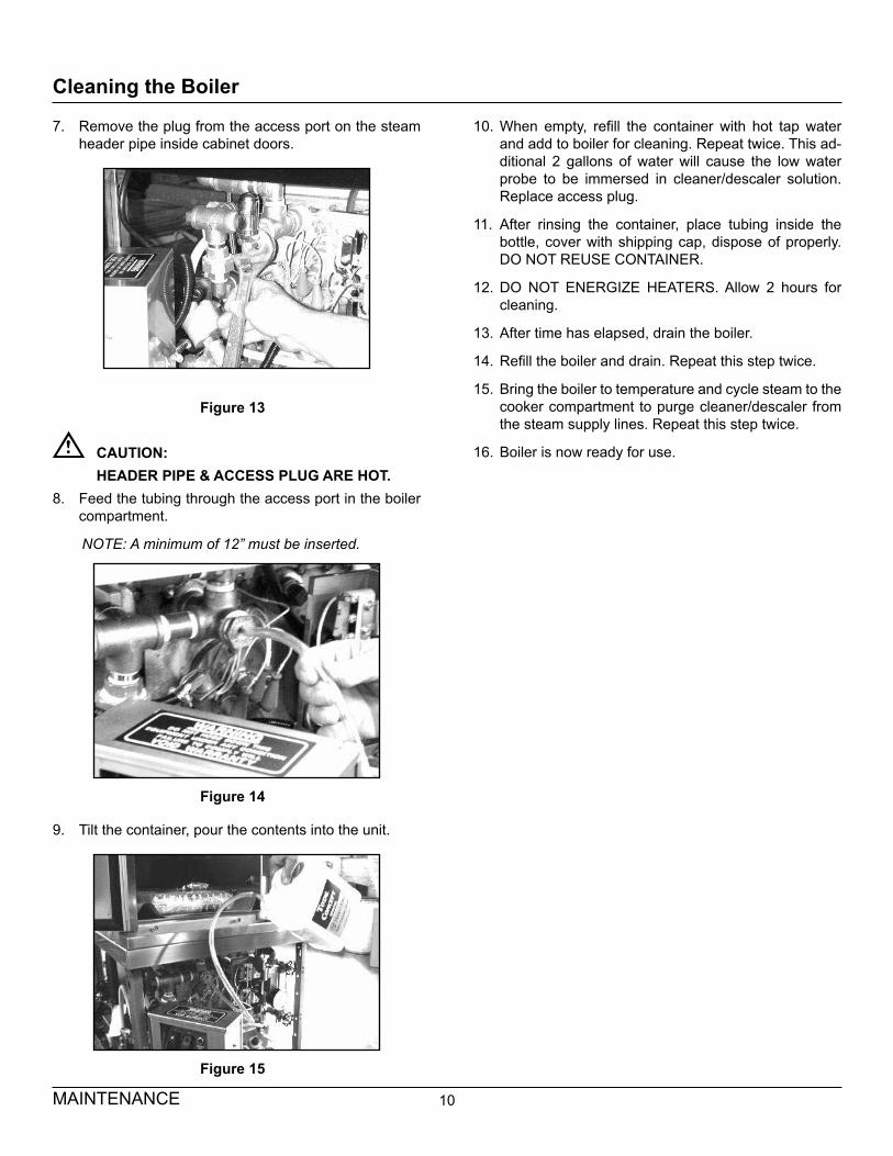
7. Remove the plug from the access port on the steam header pipe inside cabinet doors.
Figure 13
CAUTION:HEADER PIPE & ACCESS PLUG ARE HOT.
8. Feed the tubing through the access port in the boiler compartment.
NOTE: A minimum of 12” must be inserted.
Figure 14
9. Tilt the container, pour the contents into the unit.
Figure 15
10. When empty, refill the container with hot tap water and add to boiler for cleaning. Repeat twice. This ad-ditional 2 gallons of water will cause the low water probe to be immersed in cleaner/descaler solution. Replace access plug.
11. After rinsing the container, place tubing inside the bottle, cover with shipping cap, dispose of properly. DO NOT REUSE CONTAINER.
12. DO NOT ENERGIZE HEATERS. Allow 2 hours for cleaning.
13. After time has elapsed, drain the boiler.
14. Refill the boiler and drain. Repeat this step twice.
15. Bring the boiler to temperature and cycle steam to the cooker compartment to purge cleaner/descaler from the steam supply lines. Repeat this step twice.
16. Boiler is now ready for use.


![Case Study 8 Maintenance of Boilers[1]](https://static.fdocuments.net/doc/165x107/577d239c1a28ab4e1e9a481d/case-study-8-maintenance-of-boilers1.jpg)


![GAS-FIRED STEAM BOILERS · GAS-FIRED STEAM BOILERS INSTALLATION, OPERATION & MAINTENANCE MANUAL P/N# 240009572, Rev. B [07/2012] MODEL PEGDID Electronic Intermittent Ignition An ISO](https://static.fdocuments.net/doc/165x107/5d5f2dac88c993e3528b930c/gas-fired-steam-boilers-gas-fired-steam-boilers-installation-operation-maintenance.jpg)

