
Gas-Fired Water BoilerGOLD CGs-4E Gas-Fired Water Boiler — Boiler Manual How it works . . . ①...
64
Part No. 550-110-282/1108 This manual must only be used by a qualified heating installer/service technician. Before installing, read all instructions, including this manual, the burner manual and any related supplements. Perform steps in the order given. Failure to comply could result in severe personal injury, death or substantial property damage. • Installation • Startup Boiler Manual • Maintenance • Parts DO NOT USE BOILER DURING CONSTRUCTION unless you provide dust-free air to the boiler area or follow the requirements given on page 9. Failure to comply could result in severe personal injury, death or sub- stantial property damage. GOLD CG s-4 E Gas-Fired Water Boiler ® ™
Transcript of Gas-Fired Water BoilerGOLD CGs-4E Gas-Fired Water Boiler — Boiler Manual How it works . . . ①...

Part No. 550-110-282/1108
This manual must only be used by a qualified heating installer/service technician. Before installing, read all instructions, including this manual, the burner manual and any related supplements. Perform steps in the order given. Failure to comply could result in severe personal injury, death or substantial property damage.
• Installation
• StartupBoiler Manual • Maintenance
• Parts
DO NOT USE BOILER DURING CONSTRUCTION unless you provide dust-free air to the boiler area or follow the requirements given on page 9. Failure to comply could result in severe personal injury, death or sub-stantial property damage.
GOLD CGs-4EGas-Fired Water Boiler
®
™

Part number 550-110-282/11082
GOLD CGs-4E Gas-Fired Water Boiler — Boiler Manual
How it works . . .
① Control moduleThe control module responds to signals from the room thermostat, air pressure switch and boiler limit circuit to operate the boiler circulator, pilot burner, gas valve and inducer. When room thermostat calls for heat, the control module starts the system circulator and inducer.The control module runs the inducer long enough to purge the boiler flue passages, then opens the pilot valve and activates pilot ignition spark.The control module allows up to 15 seconds to establish pilot flame. If flame is not sensed within 15 seconds, the control module will turn off the gas valve, flash the Flame light, and then enter a 15-second postpurge. The control module will then start a new cycle. This will continue indefinitely until pilot flame is established or power is interrupted. Once pilot flame is proven, the control module opens the gas valve to allow main burner flame.When the room thermostat is satisfied, the control module turns off the gas valve, operates the inducer for a 15-second postpurge and waits for the next heat call.
The control module indicator lights show normal sequence when the lights are on steady. When a problem occurs, the control module flashes combinations of lights to indicate the most likely reason for the problem (see page 45).
② TransformerThe control transformer reduces line voltage to 24 volts for the gas valve and limit circuit.
③ InducerThe inducer pulls flue gases through the boiler, causing air to be pulled in through the air intake opening. The inducer pushes the flue gases through the vent pipe as well.
④ Air pressure switchThe air pressure switch signals the control module, telling the control module whether air is moving through the inducer.
⑤ Water temperature limit switchThe water temperature limit switch turns off the gas valve if the temperature in the boiler goes above its setting. (The circula-tor will continue to run as long as there is a call for heat.)
⑥ Boiler circulatorThe boiler circulator circulates water through the external (system) piping. The circulator is shipped loose, and can be mounted on either the boiler supply or return piping. The factory-installed circulator wiring harness provides ample length for either location. NOTE — The control module provides a pump exercising routine. If the boiler is not operated for 30 days, the control module will power the circulator for 30 seconds, then turn off.
⑦ Timer relay (not visible, mounted below control module on interior panel)The timer relays delays high fire for 60 seconds.
a supply to system
b return from system
c combustion air inlet
d flue outlet
e gas valve
f pressure/temperature gauge
g relief valve (not visible)
h air vent connection
i flame rollout switch
j air inlet box
k pilot burner and bracket
l stainless steel burners
m cast iron boiler sections
n flue collector
o junction box
Other boiler components:

Part number 550-110-282/11083
GOLD CGs-4E Gas-Fired Water Boiler — Boiler Manual
GOLD CGs-4E Gas-Fired Induced-Draft Water Boiler

Part number 550-110-282/11084
GOLD CGs-4E Gas-Fired Water Boiler — Boiler Manual
Contents
Hazard definitionsThe following defined terms are used throughout this manual to bring attention to the presence of hazards of various risk levels or to important information concerning the life of the product.
Indicates presence of hazards that will cause severe personal injury, death or substantial property damage.
Indicates presence of hazards that can cause severe personal injury, death or substantial property damage.
Indicates presence of hazards that will or can cause minor personal injury or property dam-age.
Indicates special instructions on installation, operation or maintenance that are important but not related to personal injury or property damage.
How it works ....................................................2–3
Hazard definitions ............................................... 4
Please read before proceeding ............................ 5
1 Prepare boiler location ...................................6–11
2 Prepare boiler ...............................................12–13
3 Water piping .................................................14–23
4 Venting & combustion air ................................... 24
5 Gas piping ......................................................... 25
6 Field wiring ....................................................... 26
7 Start-up ........................................................27–30
8 Check-out procedure ......................................... 31
9 Operation .....................................................32–36
10 Service and maintenance .............................37–42
11 Troubleshooting ............................................43–53
12 Replacement parts .......................................54–61
13 Dimensions and ratings ................................62–63

Part number 550-110-282/11085
GOLD CGs-4E Gas-Fired Water Boiler — Boiler Manual
Please read before proceeding
Installer Read all instructions before installing. Fol-
low all instructions in proper order to prevent personal injury or death.
• AlsorefertoCGsVenting Supplements.• Considerpiping and installation when determining boiler
location.• Anyclaims for damage or shortage in shipment must be
filed immediately against the transportation company by the consignee.
User• This manual is for use only by your qualified heating
installer/service technician.• PleaserefertotheUser’s Information Manual for your refer-
ence.• Werecommendregularservice by a qualified service techni-
cian, at least annually.
The boiler contains ceramic fiber and fiberglass materials. Use care when handling these materials per instructions on page 64 of this manual. Failure to comply could result in severe personal injury.
When calling or writing about the boiler— Please have the boiler model number from the boiler rating label and theCPnumberfromtheboilerjacket.YoumaylisttheCPnumberinthespaceprovidedontheInstallationandservice certificate found on page 31.
Readandfollowthespecial instructionsfortheCommonwealthofMassachusetts, locatedonpage36ofthismanual.
Failure to adhere to the guidelines on this page can result in severe personal injury, death or substantial property damage.
When servicing boiler —• Toavoidelectricshock,disconnectelectricalsupplybefore
performing maintenance.
• Toavoidsevereburns,allowboilertocoolbeforeperform-ing maintenance.
Boiler operation —• Do not block flow of combustion or ventilation air to
boiler.
• Shouldoverheatingoccurorgassupplyfailtoshutoff,donot turn off or disconnect electrical supply to circulator. Instead, shut off the gas supply at a location external to the appliance.
• Donotuse thisboiler ifanyparthasbeenunderwater.Immediately call a qualified service technician to inspect the boiler and to replace any part of the control system and any gas control that has been under water.
Boiler water —• Donotusepetroleum-basedcleaningorsealingcompounds
in boiler system. Water seal deterioration will occur, caus-ing leakage between sections. This can result in substantial property damage.
• Donotuse“homemadecures”or“boilerpatentmedicines”.Severepersonalinjury,deathorsubstantialpropertydam-age may result.
• Continualfreshmakeupwaterwillreduceboilerlife.Min-eral buildup in sections reduces heat transfer, overheats cast iron,andcauses section failure.Additionofoxygenandother gases can cause internal corrosion. Leaks in boiler or piping must be repaired at once to prevent makeup water.
• Donotaddcoldwatertohotboiler.Thermalshockcancause sections to crack.
Glycol — potential fire hazard —
Allglycolisflammablewhenexposedtohightemperatures.Ifglycol is allowed to accumulate in or around the boiler or any other potential ignition source, a fire can develop. In order to prevent potential severe personal injury, death or substantial property damage from fire and/or structural damage:
• Neverstoreglycolofanykindneartheboileroranypoten-tial ignition source.
• Monitorand inspect the systemandboiler regularly forleakage. Repair any leaks immediately to prevent possible accumulation of glycol.
• Neveruseautomotiveantifreezeorethyleneglycolinthesystem. Using these glycols can lead to hazardous leakage of glycol in the boiler system.

Part number 550-110-282/11086
GOLD CGs-4E Gas-Fired Water Boiler — Boiler Manual
Prepare boiler location — codes & checklist1a
Installations must follow these codes:• Local,state,provincial,andnationalcodes,laws, regulations and ordinances.• NationalFuelGasCode,ANSIZ223.1–latestedition.• StandardforControlsandSafetyDevicesforAutomaticallyFiredBoilers,ANSI/
ASMECSD-1,whenrequired.• NationalElectricalCode.• ForCanadaonly:B149.1orB149.2InstallationCode,CSAC22.1CanadianElectri-
calCodePart1andanylocalcodes.
TheCGs-4Eboilergasmanifoldandcontrolsmetsafelightingandother performance criteria when boiler underwent tests specified inANSIZ21.13–latestedition.
Before locating the boiler, check the following:• Checkfornearbyconnectionto:
• System water piping• Ventingconnections• Gassupplypiping• Electrical power
• Checkareaaroundboiler.Remove any combustible materials, gasoline and other flammable liquids, or other contaminants.
Failure to keep boiler area clear and free of combustible materials, gasoline and other flammable liquids and vapors can result in severe personal injury, death or substantial property damage.
• Boiler must be installed so that gas control system components are protected from dripping or spraying water or rain during operation or service.
• Ifnew boiler will replace existing boiler, check for and correct system problems, such as:
1. Systemleaks causing oxygen corrosion or section cracks from hard water deposits.
2. Incorrectly-sized expansion tank.3. Lack of antifreeze in boiler water causing system and boiler to freeze and
leak.

Part number 550-110-282/11087
GOLD CGs-4E Gas-Fired Water Boiler — Boiler Manual
Prepare boiler location — clearances1bFigure 2 Required MINIMUM clearances
Figure 1
Recommended SERVICE clearances
(see WARNING
below)
Recommended SERVICE clearances (Fig. 1)1. Provide clearances for cleaning and servicing the boiler and for
accesstocontrolsandcomponents.SeeFigure1forrecommenda-tions.
2. Provide at least screwdriver clearance to jacket front panel screws for removal of front panel for inspection and minor service. If unable to provide at least screwdriver clearance, install unions and shutoff valves in system so boiler can be moved for servicing.
Required MINIMUM clearances (Fig. 2) Never install the boiler in a space with clear-
ances less than the minimum clearances shown in Figure 2. Failure to comply can result in severe personal injury, death or substantial property damage and reduced boiler life.
1. Hot water pipes: at least ¹⁄₂ inch from combustible material.
2. Single-wall vent pipe: at least 6 inches from combustible mate-rial.
3. Type B double-wall metal vent pipe: refer to vent manufacturer’s recommendation for clearances to combustible material.
If any clearance is less than in Figure 1, provide openings for combustion and ventilation air located on the wall or door opposite the boiler FRONT (see Figure 2).
These openings must be located as shown in Figure 2 to provide proper air flow around the boiler. The free area of each opening (after deducting for louvers) must be at least one square inch per 1,000 Btuh of boiler input. If the building is of unusually tight construction (see page 10 for definition), the air openings must connect directly to outside or the building must have air openings to the outside as specified on page 10.
If clearances are equal to or greater than Figure 1, see pages 10 and 11 for location and sizing of combustion air openings.
Failure to comply can result in severe personal injury, death or substantial property damage and reduced boiler life.
FlooringTheCGs-4Eboilerisapprovedforinstallationoncombus-tible flooring, but must never be installed on carpeting.
Donotinstallboileroncarpetingevenif foundation is used. Fire can result, causing severe personal injury, death or substantial property damage.
Foundation1. Provide a solid brick or minimum 2-inch thick concrete
foundation pad if any of the following is true:• floorcanbecomeflooded.• theboilermountingareaisnotlevel.
2. Minimumdimensionsare25” length by:
Minimum foundation width:
CGs-4E 15”
Residential garage installationsTake the following special precautions when installing the boiler in a residential garage. If the boiler is located in a residentialgarage,perANSIZ223.1:
• Mounttheboileraminimumof18 inches above the floor of the garage to assure the burner and ignition devices will be no less than 18 inches above the floor.
• Locateorprotect the boiler so it cannot be damaged by a moving vehicle.

Part number 550-110-282/11088
GOLD CGs-4E Gas-Fired Water Boiler — Boiler Manual
Prepare boiler location — vent system1c Failure to follow all instructions can result in flue gas spillage and carbon monoxide emissions, causing severe
personal injury or death.
When removing boiler from an existing common vent system:At the timeof removalof anexistingboiler, the fol-lowing steps shall be followed with each appliance remaining connected to the common venting system placed in operation, while the other appliances remain-ing connected to the common venting system are not in operation.
a. Seal any unused openings in the common venting system.
b. Visually inspect the venting system for proper size and horizontal pitch and determine there is no blockage or restriction, leakage, corrosion or other deficiencies which could cause an unsafe condi-tion.
c. Test vent system — Insofar as is practical, close all building doors and windows and all doors between the space in which the appliances remaining con-nected to the common venting system are located and other spaces of the building. Turn on clothes dryers and any appliance not connected to the com-mon venting system. Turn on any exhaust fans, such as range hoods and bathroom exhausts, so they will operateatmaximumspeed.Donotoperateasum-merexhaustfan.Closefireplacedampers.
d. Place in operation the appliance being inspected. Followthelighting/operatinginstructions.Adjustthermostat so appliance will operate continuously.
e. Test for spillage at draft hood relief opening after 5 minutes of main burner operation. Use the flame of a match or candle.
f. Afterithasbeendeterminedthateach appliance remaining connected to the common venting system properly vents when tested as outlined above, return doors, windows, exhaust fans, fireplace dampers, and any other gas-burning appliance to their previ-ous conditions of use.
Any improper operation of common venting systemshould be corrected so the installation conforms with theNationalFuelGasCode,ANSIZ223.1-latestedition.Correctbyresizingtoapproachtheminimumsizeasdetermined using the appropriate tables in Part 11 of that code. Canadian installations must comply withB149.1orB149.2InstallationCode.
CGs-4E special vent system
Vent system
TheCGs-4Eboilerrequiresaspecialventsystem,de-signedforpressurizedventing.ModelCGs-4EisratedANSIZ21.13Category IV (pressurized vent, likely to condense in the vent).
You may use any of the vent systems covered by theCGsVentingSupplementsincludedintheenvelopeas-sembly.TheCGsventstarterisaspecialitem,designedonlyforCGsandCGs-4Eboilers,availablefromeachvendor.DonotattempttoconnecttheventtotheCGs-4Eboilerwithanyothermeans.
DO NOT mix components from different systems. The vent system could fail, causing leakage of flue products into the living space.
Vent termination and combustion air supply
TheCGs-4Eboilermaybeventedthroughtherooforthrough a side wall. Follow the appropriate vent supple-ment for the vent system chosen. The maximum vent length depends on boiler size. Refer to the vent supple-ment to determine acceptable vent length.
CombustionairfortheCGs-4Eboilermustbeducteddirectly to the boiler from outside. For outside air (direct vent installation), two options are available for the flue/air termination. The air supply must ALWAYS terminate at the same location as the flue, using either:
1. Vertical direct vent installation. Obtain the Weil-McLainThrough-Roof or Through-Unused Chimney termination kit and supplement. Refer to Vertical Direct VentingVenting Supplement,packed with the kit, and to the vent manufacturer’s instructions for the vent material chosen.
2. Sidewall direct vent installation. Use the Vent/Air Intake termination kit shipped with the boiler. Refer to CGs Direct Venting: Sidewall & Direct Exhaust Venting: Vertical or SidewallVentingSupplementshipped with the boiler.
DO NOT COMMON VENT—DonotinstalltheCGs-4Eintoacommonventwithanyotherappliance.Thiswillcause flue gas spillage or appliance malfunction, resulting in possible severe personal injury, death or substantial property damage.
Inspect existing chimney before installing boiler. Failure to clean or replace perforated pipe or tile lining will cause severe personal injury or death.

Part number 550-110-282/11089
GOLD CGs-4E Gas-Fired Water Boiler — Boiler Manual
Prepare boiler location — contamination1d
Table 1 Corrosive or destructive contaminants and likely locations
AllCGs-4Eboilersmustbedirectvented(usingductedoutsideair).Thevent/airterminationmustbeinstalledinalocationthatisfreeofthecontaminantslistedbelow.Allowingtheboiler to operated with contaminated air can cause damage to the boiler and vent system, resulting in possible severe personal injury, death or substantial property damage.
Please review the following information on potential combustion air contamination problems.
Refer to Table 1 for products and areas which may cause contaminated combustion air.
CONSTRUCTION DUST HAZARD — Airborneparticulates,suchasdrywalldustorfiberglassdust,willcauseblockageoftheCGs-4Eburners,resultingincarbonmonoxideproduction, a fire hazard, or building freeze damage. If the boiler is operated during construction, you must isolate the boiler air supply to provide clean air for combus-tion. Follow the instruction manual guidelines for piping intake air. If you are unable to ensure uncontaminated air in the boiler air intake at all times, you must inspect the boiler at least once weekly. When inspecting, clean the burners if necessary using the procedure given on page 39. Failure to follow these guidelines could result in severe personal injury, death or substantial property damage.
Products to avoid Areas likely to have contaminants
Spray cans containing chloro/fluorocarbons Dry cleaning/laundry areas and establishments
Permanent wave solutions Swimming pools
Chlorinated waxes/cleaners Metal fabrication plants
Chlorine-based swimming pool chemicals Beauty shops
Calcium chloride used for thawing Refrigeration repair shops
Sodium chloride used for water softening Photo processing plants
Refrigerant leaks Auto body shops
Paint or varnish removers Plastic manufacturing plants
Hydrochloric acid/muriatic acid Furniture refinishing areas and establishments
Cements and glues New building construction
Antistatic fabric softeners used in clothes dryers Remodeling areas
Chlorine-type bleaches, detergents, and cleaning solvents found in household laundry rooms
Garages with workshops
Adhesives used to fasten building products and other similar products
Buildings under construction (where air is contaminated with particulates)
Airborne particulates (drywall dust, fiberglass particles, road or gravel dust, lint, etc.)

Part number 550-110-282/110810
GOLD CGs-4E Gas-Fired Water Boiler — Boiler Manual
Prepare boiler location — air openings1e
Special considerations
Tight construction
ANSI Z223.1 defines unusually tight constructionwhere:
1. Walls and ceilings exposed to the outside atmo-sphere have a continuous water vapor retarder with a rating of 1 perm or less with openings gasketed, and . . .
2. Weather-stripping has been added on openable windows and doors, and . . .
3. Caulking or sealants are applied to areas such asjoints around windows and door frames, between sole plates and floors, between wall-ceiling joints, between wall panels, at penetrations for plumbing, electrical, and gas lines, and in other openings.
For buildings with such construction, provide air open-ings into the building from outside, sized per the ap-propriate case in Figure 3 if appliances are to use inside air for combustion and ventilation.
Exhaust fans and air movers
The appliance space must never be under a negative pressure unless all appliances are installed as direct vent. Alwaysprovideairopeningssizednotonlytothedimen-sions required for the firing rate of all appliances, but also to handle the air movement rate of the exhaust fans or air movers using air from the building or space.
Motorized air dampers
If the air openings are fitted with motorized dampers, electrically interlock the damper to:
• Preventtheboilerfromfiringifthedamperisnotfully open.
• Shuttheboilerdownshouldthedamperclosedur-ing boiler operation.
To accomplish this interlock, wire an isolated contact (proving the damper open) in series with the thermo-stat input to the boiler. The boiler will not start if this contact is open, and will shut down should it open during operation.
Combustion air requirements ✷
Using outside air — direct vent onlyCombustionairmustbeducteddirectlyfromoutsidetotheCGs-4Eboilerair intake fitting. This method is defined as direct vent (also referred to as sealed combustion). Refer to the appropriate vent supplement and the instructions in this manual. Two options are available: sidewall or vertical directvent.Eachrequiresaspecialventcomponentkit.
Sizing air openings ✷Airopeningsprovideforventilationtopreventoverheatingoftheboilercontrolsandboilerspace.Airisalsoneededforotherapplianceslocatedin the same space.
Use Figure 3,page11,selectingtheappropriateinstallationconditions.NotethatthesizinggiveninFigure3appliesonlytoCGs-4Einstallationswithclearances no smaller than shown in Figure 1, page 7 of this manual. For smaller clearances, regardless of how the air openings are arranged, two openingsprovidingfreeareaof1squareinchper1,000Btuhinputofallappliances in the space are required.
Airopeningsmustbesizedtohandleallappliancesandair movers (exhaust fans, etc.) using the air supply.
ThesizinggiveninFigure3isbasedontheNationalFuelGasCode,ANSIZ223.1,allowingadequateairopeningforgravity-ventedgasappliances(CategoryI).TheCGs-4EboilerisratedCategoryIV(pressurizedvent),and has different requirements for combustion and ventilation air, reflected by the special sizing instructions given in Figure 3. The air openings rec-ommended in Figure 3 will allow adequate ventilation and combustion air provided the boiler room is not subjected to negative pressure due to exhaustfansorothermechanicalventilationdevices.RefertotheNationalFuelGasCodefordealingwithotherconditions.
Louver allowanceThe free area of openings means the area after reduc-tion for any installed louvers or grilles.Besuretoconsider this reduction when sizing the air openings.
Air opening location and sizing requirements de-pend on the clearances around the boiler.Checkthe boiler placement compared to Figure 1, page 7.
If all clearances are at least equal to Figure 1, page 7, apply the sizing and placement of openings given on pages 10 and 11.
If ANY clearance is less than Figure 1, page 7, you must provide air openings sized and located as shown in Figure 2, page 7. DO NOT apply the sizing and location information shown on page 10 or 11. The Figure 2 air openings are required even if the boiler is direct vented (outside air piped to the boiler air intake as described in this manual). These openings ensure adequate air circulation around the boiler for cooling, even if the boiler does not use inside air for combustion.
✷

Part number 550-110-282/110811
GOLD CGs-4E Gas-Fired Water Boiler — Boiler Manual
Figure 3 Sizing air openings for CGs-4E installations ✷

Part number 550-110-282/110812
GOLD CGs-4E Gas-Fired Water Boiler — Boiler Manual
Place boiler/crate near position1. Leave boiler in crate and on pallet until installation
site is ready.2. Moveentirecrateandpalletnexttoselectedloca-
tion.3. Remove crate.4. Remove boiler from pallet.
Donotdropboilerorbumpjacketonfloororpallet.Damagetoboilercan result.
a. Tilt left side of boiler up and place a board under left legs.
b. Tilt boiler the other way and place a board under right legs.
c. Slideboilerbackwardoffpalletandintoposi-tion.
5. Checklevel.a. Shimlegs,ifnecessary.b. Donotalterlegs.
Prepare boiler — placement & setup2a
Table 2 Manifold orifice sizing
Location Natural gas Propane gas
U. S.0-2,000 ft over 2,000 ft 0-2,000 ft over 2,000 ft
2.55 mm (Note 1) 1.60 mm (Note 1)
Canada0-2,000 ft 2,000-4,500 0-2,000 ft 2,000-4,500
2.55 mm #41 1.60 mm 1.45 mm
Note 1: For elevations above 2,000 feet, contact your local Weil-McLain sales office for details.
Inspect orifices and burners1. Remove front jacket door. Remove inlet air box top
panel (see Figure 27, item 13, page 56).
2. Check for correctly-sized manifold orifices. SeeTable 2 for sizing. (The orifice size is stamped on the orifice spud barrel.)
Correctly-sized manifold orificesmust be used. Failure to do so will result in severe personal injury, death or substantial property dam-age.
3. Reinstall inlet air box top panel.
Orifice replacement procedure (when required)
1. Remove the screws securing the inlet air box top panel.
2. Remove inlet air box top panel and inspect the fiber gasket.Verifythegasketisingoodconditionandcanseal around the complete perimeter of the air box. Replace the gasket if necessary.
3. Using a 7/16”open-endwrench,removetheburnerorifices from the manifold.
4. Applyasmallamountofpipedopetoeachofthenew orifices and install in the manifold using a 7/16”open-endwrench.Makesuretheorificesarealignedcorrectly, not cross-threaded in the manifold tap-pings.
Use only pipe dope compatible with propane gas, even if boiler is to be operated on natural gas. Failure to comply could result in severe per-sonal injury, death or substantial property damage.
5. Carefullyreplacetheinletairboxtoppanel,makingsure the gasket is in place will seal all around the perimeter.
6. Followthecheck-outprocedure,Section8 page 31, to assure the boiler is now operating properly after orifices are replaced.
Inlet air box top panel must be in position during boiler operation. Failure to do so could result in severe personal injury, death or substantial property damage.

Part number 550-110-282/110813
GOLD CGs-4E Gas-Fired Water Boiler — Boiler Manual
Prepare boiler — pressure test2bHydrostatic pressure testPressure test boiler before attaching water or gas piping (except as noted below) or electrical supply.
Prepare boiler for test1. Removetheshippingnipple(fromCGs-4Esupply
tapping) and remove the boiler relief valve. Tempo-rarily plugthereliefvalvetappingwitha¾”NPTpipe plug.
2. Remove 1¼” nipple, reducing tee and drain valve from circulator hardware and pressure/temperature gauge carton. Install in boiler return connection as shown on page 3 and Figure 29, page 60. Install circulator on either the return or supply.
3. Remove1¼”nipple,1¼”x1¼”x½”teeandpres-sure/temperature gauge from circulator hardware and pressure/temperature gauge carton. Pipe to boiler supply connection as shown on page 3 and Figure 29, page 60. (Use pipe dope sparingly.)
4. Connectahosetoboilerdrainvalve,theotherendconnectedtoafreshwatersupply.Makesurehosecan also be used to drain boiler after test.
5. Connectanippleandshutoffvalvetosystemsupplyconnectiononthe1¼”tee.Thisvalvewillbeusedtobleedairduringthefill.(Valveandnipplearenotincluded with boiler.)
6. Connectanippleand shutoffvalve to systemre-turn connection (at circulator flange if circulator installed on return). This valve will be used to bleed airduringthefill.(Valveandnipplearenotincludedwith boiler.)
Fill and pressure test1. Open the shutoff valves you installed on supply and
return connections.
2. Slowlyopenboilerdrainvalveandfreshwatersup-ply to fill boiler with water.
3. When water flows from shutoff valves, close boiler drain valve.
4. Closeshutoffvalves.
5. Slowlyreopenboilerdrainvalveuntiltestpressureon the pressure/temperature gauge reaches no more than:
• 45 psig for boilers with 30 psig relief valve.
• 75 psig for boilers with 50 psig relief valve.
6. Test for no more than 10 minutes at:
• 45 psig for boilers with 30 psig relief valve.
• 75 psig for boilers with 50 psig relief valve.
Do not leave boiler unattended. Acoldwaterfillcouldexpandandcause excessive pressure, resulting in severe personal injury, death or substantial property damage.
7. Makesureconstantgaugepressurehasbeenmain-tained throughout test.Check for leaks.Repair iffound.
Leaks must be repaired at once. Failure to do so can damage boiler, resulting in substantial property damage.
Donotusepetroleum-based clean-ing or sealing compounds in boiler system. Severe damage to boilerwill occur, resulting in substantial property damage.
Drain and remove fittings1. Disconnectfillwaterhosefromwatersource.
2. Drainboileratdrainvalveorouthose,whicheverprovides best access to drain. Remove hose after draining if used to drain boiler.
3. Remove nipples and valves unless they will remain for use in the system piping.
4. Removeplugfromreliefvalvetapping.Seepage14to replace relief valve.

Part number 550-110-282/110814
GOLD CGs-4E Gas-Fired Water Boiler — Boiler Manual
Water piping — general information3a
Table 3 Water pipe size (based on 20°F rise)
Boilermodel
number
Tosystem
Fromsystem
CGs-4E 1” 1”
Note: The boiler supply and return connections, the return/ drain tee and the supply/gauge tee supplied with the boiler are 1¼” NPT. One of the circulator flanges supplied with the boiler is 1¼”. The other circulator flange is the size of the recommended system piping shown above.
General piping informationIfinstallationistocomplywithASMEorCanadianrequirements,anad-ditional high temperature limit is needed. Install control in supply piping betweenboilerandisolationvalve.Setsecondcontroltominimum20°Fabovesetpointoffirstcontrol.Maximumallowablesetpointis240°F.SeeSection9b, page 34 for wiring.
Alow water cutoff device is required when boiler is installed above ra-diation level or by certain state or local codes or insurance companies. Use lowwatercutoffdesignedforwaterinstallations.Electrodeprobe-typeisrecommended. Purchase and install in tee in supply piping above boiler.
Use backflow check valve in cold water supply as required by local codes.
Pressure/temperature gaugeInstall pressure/temperature gauge in tee on supply piping (as shown in drawing on page 3).
Relief valveInstallreliefvalveverticallyin¾”tappingonsideofboiler.SeeFigure 4 or 5, page 15, and the tag attached to the relief valve for manufacturer’s instructions.
CirculatorThe circulator is shipped loose (wiring pre-attached to boiler) to allow you to locate it either in the return or supplypiping,asdesired.Seepage3foratypicalinstal-lation. Pipe the expansion tank to the suction side of the circulator whenever possible. Install an air separator in thesupplypiping.Connecttheexpansiontanktotheairseparator only if the separator is on the suction side of thecirculator.Alwaysinstallthesystemfillconnectionat the same point as the expansion tank connection to the system. Figures 4 and 5, page 15, show typical near-boiler piping connections.
System water pipingSeeFigure 4 (diaphragm-type or bladder-type expan-sion tank) or Figure 5 (closed-type expansion tank) on page 15, and Table 3 below, for near-boiler and single-zonesystemsdesignedforreturnwateratleast130°F.
Seepages16-17tocompletemultiple-zonepipingorpages 18-23 to complete piping for radiant heating systems or converted gravity systems (large-volume systems originally designed for circulation by natural convection rather than a pump).
Chillers or air handling units: Install boiler such that —
• Chilledmedium,ifused,ispipedinparallelwithheating boiler. Use appropriate valves to prevent chilled medium from entering boiler. ConsultI=B=RInstallationandPipingGuides.
• If boiler is connected to heating coils located inair handling units where they can be exposed to refrigerated air, use flow control valves or other au-tomatic means to prevent gravity circulation during coolingcycle.Circulationofcoldwaterthroughtheboiler could result in damage to the heat exchanger, causing possible severe personal injury, death or substantial property damage.
To avoid water damage or scalding due to relief valve operation:
• Dischargelinemustbeconnectedtoreliefvalveoutletandrun to a safe place of disposal. Terminate the discharge line to eliminate possibility of severe burns should the valve discharge.
• Dischargelinemustbeasshortaspossibleandbethesame size as the valve discharge connection throughout its entire length.
• Dischargelinemustpitch downward from the valve and terminate atleast6”abovethefloordrainwhereanydischargewillbeclearlyvisible.
• Thedischargelineshallterminate plain, not threaded, with a mate-rialserviceablefortemperaturesof375°Forgreater.
• Do not pipe the discharge to any place where freezing could occur.
• No shutoff valve shall be installed between the relief valve and boiler, orinthedischargeline.Donotplugorplaceanyobstructioninthedischarge line.
• Failure to comply with the above guidelines could result in failure of the relief valve to operate, resulting in possibility of severe personal injury, death or substantial property damage.
• Test the operation of the valve after filling and pressurizing system byliftingthelever.Makesurethevalvedischargesfreely.Ifthevalvefails to operate correctly, replace it with a new relief valve.
Part number 550-110-282/110815
GOLD CGs-4E Gas-Fired Water Boiler — Boiler Manual
Water piping — single-zone system3b
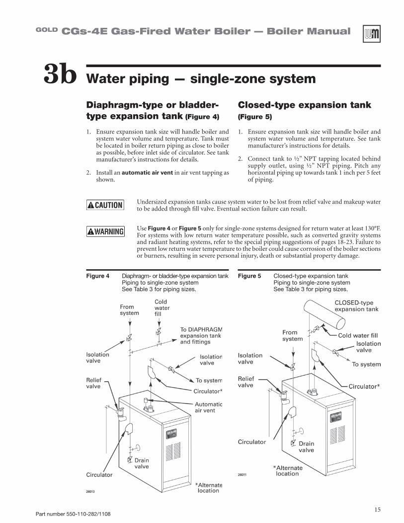
Figure 4 Diaphragm- or bladder-type expansion tank Piping to single-zone system See Table 3 for piping sizes.
Figure 5 Closed-type expansion tank Piping to single-zone system See Table 3 for piping sizes.
Diaphragm-type or bladder-type expansion tank (Figure 4)
1. Ensureexpansiontanksizewillhandleboilerandsystem water volume and temperature. Tank must be located in boiler return piping as close to boiler aspossible,beforeinletsideofcirculator.Seetankmanufacturer’s instructions for details.
2. Install an automatic air vent in air vent tapping as shown.
Closed-type expansion tank (Figure 5)
1. Ensureexpansiontanksizewillhandleboilerandsystem water volume and temperature. See tankmanufacturer’s instructions for details.
2. Connect tankto½”NPTtapping locatedbehindsupply outlet, using ½” NPT piping. Pitch anyhorizontal piping up towards tank 1 inch per 5 feet of piping.
Undersized expansion tanks cause system water to be lost from relief valve and makeup water tobeaddedthroughfillvalve.Eventualsectionfailurecanresult.
Use Figure 4 or Figure 5 onlyforsingle-zonesystemsdesignedforreturnwateratleast130°F.For systems with low return water temperature possible, such as converted gravity systems and radiant heating systems, refer to the special piping suggestions of pages 18-23. Failure to prevent low return water temperature to the boiler could cause corrosion of the boiler sections or burners, resulting in severe personal injury, death or substantial property damage.

Part number 550-110-282/110816
GOLD CGs-4E Gas-Fired Water Boiler — Boiler Manual
Water piping — multiple zones3cPiping multiple zonesFollow instructions on pages 14 and 15 to install near-boilerorsingle-zonepiping.(AlsorefertoPiping for radiant heating systems or converted gravity sys-tems, below, if applicable.)
SeeFigure 6 or Figure 7, page 17, to complete instal-lation.
Zoning with circulators (Figure 6) (return temp over 130°F)1. Size each circulator to individual circuit require-
ments.2. Donotinstallcirculatoronboiler(exceptforpri-
mary/secondary piping).3. Install isolation (balancing) valves to adjust flow to
distribute heat to all zones.
4. Install and wire a separate relay for each zone cir-culator.
Zoning with zone valves (Figure 7) (return temp over 130°F)1. Install isolation (balancing) valves to adjust flow to
distribute heat to all zones.
2. Provide a separate 24-volt transformer to power the zonevalves.Sizethetransformertohandlethetotalrated load of all connected zone valves.
Piping for radiant heating systems or converted gravity systems
Converted gravity (or steam) systemsWhenever possible, use the primary/secondary piping shown in Figures 8 or 9 on page 19. This piping design allows changing boiler flow rate without affecting pri-mary circuit flow rate.
If Figures 8 or 9 cannot be used, use the boiler-bypass piping shown in Figure 10 or Figure 11 onpage21.Youcan also use the piping shown in Figure 12 on page 23 (system-bypass), if the reduced flow rate in the heating system will not cause heat distribution problems.
Failure to prevent low return water temperature to the boiler could cause corrosion of the boiler sec-tions or burners, resulting in severe personal injury, death or substantial property damage.
Radiant heating systemsPreferably, use primary/secondary piping, as shown in Figures 8 or 9 on page 19.Alternatively, use themethod of either Figure 10 or Figure 11 on page 21. Do not use the piping of Figure 12 (system-bypass), because this method does not control radiant system supply temperature.
If radiant system tubing has no oxygen barrier, a heat exchanger must be used.
Radiant heating system piping should include a means of regulating the boiler return water temperature and the system supply temperature (such as provided by an injection pumping control).Boilerreturnwatertemperaturewillbeadequatelycontrolledusingthemethodsshown in this manual provided the system supply temperature is relatively constant.
DO NOT apply the methods in this manual if the system is equipped with an outdoor reset control. Instead, provide controls and piping which can regulate the boiler return water temperatureatnolessthan130°Fregardlessofsystemsupplytemperature.ContactyourWeil-McLainrepresentativeforsuggestedpipingandcontrolmethods.Failuretopreventcold return water temperature to the boiler could cause corrosion damage to the sections or burners, resulting in possible severe personal injury, death or substantial property dam-age.

Part number 550-110-282/110817
GOLD CGs-4E Gas-Fired Water Boiler — Boiler Manual
Figure 6 Zoning with circulators — return water 130°F or higher.
Figure 7 Zoning with zone valves — return water 130°F or higher.
1 Boiler isolation (balancing)valves
2 Flow/check valve
3 Systemorzonecirculator
5 Zonevalve
6 Drainvalve
9 Relief valve
10Automaticairvent(withdiaphragm-typeexpansiontank),orconnectto tank fitting (closed-type expansion tank). DO NOT use an automatic air vent when using closed-type expansion tank. It would allow air to leave the system, causing waterlogging of the expansion tank.
11 Fill valve
12Diaphragm-typeorbladder-typeexpansiontank,ifused(Forclosed-type expansion tank, pipe from top of air separator to tank fitting as in Figure 5, page 15.)
13Airseparatorandautomaticvent,ifused(Notethatthefillvalvemustalways be connected to the expansion tank, regardless of location of expansion tank circulator or air separator.
3c Water piping — multiple zones (continued)
For systems with possible low return-water temperature (such as converted gravity systems, radiant heating systems and heat pump systems), refer to the special piping suggestions of Figures 8 - 12, as applies. Failure to prevent sustained low return water temperature to the boiler could cause corrosion of the boiler sections, resulting in severe personal injury, death or substantial property damage.

Part number 550-110-282/110818
GOLD CGs-4E Gas-Fired Water Boiler — Boiler Manual
Piping — low temp systems3d
Failure to prevent low return water temperature to the boiler could cause corrosion of the boiler sections or burners, resulting in severe personal injury, death or substantial property damage.
Radiant heating system piping should include a means of regulating the boiler return water temperature and the system supply temperature (such as provided by an injec-tion pumping control).
Boilerreturnwatertemperaturewillbeadequatelycontrolledusingthemethodsshownin this manual provided the system supply temperature is relatively constant.
DO NOT apply the methods of this manual if the system is equipped with an outdoor reset control. Instead, provide controls and piping which can regulate the boiler re-turn water temperature at no less than 130°F regardless of system supply temperature. ContactyourWeil-McLainrepresentativeforsuggestedpipingandcontrolmethods.
Failure to prevent cold return water temperature to the boiler could cause corrosion damage to the sections or burners, resulting in possible severe personal injury, death or substantial property damage.
Primary/secondary (preferred) bypass piping methodPrimary/secondary bypass piping is preferred because the flow rate and temperature drop in the heating circuit(s) is determined only by the heating circuit circulator(s). So adjustment of the bypass valves inthe boiler circuit will not cause a change in the heating circuit rate and temperature distribution.
Figures 8 and 9, page 19, show suggested bypass ar-rangements using primary/secondary bypass piping (preferred) for low temperature systems such as radiant heating systems or converted gravity systems. For alternatives, see pages 20 through 23.
The bypass valves in Figures 8 and 9 (items 7a and 7b) provide mixing of hot boiler outlet water with cooler system return water — set to assure a minimum return watertemperature(atleast130°F)totheboiler.Setthevalves as explained below.
Temperature gauges
Gauge4a is suggested, but optional on any system.
Gauge 4b is optional on converted gravity systems, but required on radiant heating systems — to display
the water temperature being supplied to the radiant tubing.
Gauge8 is required on all systems to assure the return water temperature is accurately set for a minimum of 130°F.Ifthisgaugeisnotavailablehowever,adjustthevalves such that the boiler-mounted temperature/pres-suregaugereadsatleast150°Fwhenthesystemreturnwateriscold(approximately60°Fwatertemperature).
Valve adjustment (Figures 8 and 9 only)
1. Setthevalveswhilethesystemiscool,settingforthecoldestexpectedwater temperature (usually60°Fsince the system will often drop to room tempera-ture between cycles).
2. Startwithvalve7a fully closed and 7b fully open.
3. Graduallyopenvalve7a while closing valve 7b until the temperature at gauge 8reads130°Fwhengauge4areads60°F.
4. Notethatvalve7a regulates the amount of hot wa-ter from the boiler supply which mixes with return water.Valve7b regulates the amount of system water flowing through the boiler secondary loop.

Part number 550-110-282/110819
GOLD CGs-4E Gas-Fired Water Boiler — Boiler Manual
1 Boilerisolation(balancing)valves
2 Flow/check valve
3 Systemorzonecirculator
4 Systemtemperaturegauges
5 Zonevalve
6 Drainvalve
7 Systemtemperaturevalves(seeinstruc-tions to the left for adjusting valves)
8 Blendtemperaturegauge
9 Relief valve
10Automaticairvent(withdiaphragm-typeexpansiontank),orconnect to tank fitting (closed-type expansion tank). DO NOT use an automatic air vent when using closed-type expansion tank. It would allow air to leave the system, causing waterlog-ging of the expansion tank.
11 Fill valve
12Diaphragm-typeorbladder-typeexpansiontank,ifused(Forclosed-type expansion tank, pipe from top of air separator to tank fitting as in Figure 5, page 15.)
13Air separator and automatic vent, if used (Note that thefill valve must always be connected to the expansion tank, regardless of location of expansion tank, circulator or air separator.)
Figure 8 Primary/secondary piping Zoning with circulators
Figure 9 Primary/secondary piping Zoning with zone valves
3d Piping — low temp systems (continued)

Part number 550-110-282/110820
GOLD CGs-4E Gas-Fired Water Boiler — Boiler Manual
Failure to prevent low return water temperature to the boiler could cause corrosion of the boiler sections or burners, resulting in severe personal injury, death or substantial property damage.
Radiant heating system piping should include a means of regulating the boiler return water temperature and the system supply temperature (such as provided by an injec-tion pumping control).
Boilerreturnwatertemperaturewillbeadequatelycontrolledusingthemethodsshownin this manual provided the system supply temperature is relatively constant.
DO NOT apply the methods of this manual if the system is equipped with an outdoor reset control. Instead, provide controls and piping which can regulate the boiler re-turn water temperature at no less than 130°F regardless of system supply temperature. ContactyourWeil-McLainrepresentativeforsuggestedpipingandcontrolmethods.
Failure to prevent cold return water temperature to the boiler could cause corrosion damage to the sections or burners, resulting in possible severe personal injury, death or substantial property damage.
3d Piping — low temp systems (continued)
BOILER-bypass piping methodThis piping method (Figures 10 and 11, page 21) is called a boiler-bypass because part of the circulator flow is bypassed around the boiler (through valve 7a). This method reduces the flow rate throughout the boiler, in order to raise the average water temperature in the boilerenoughtopreventfluegascondensation.Boiler-bypass piping is effective for some boilers — including the CGs-4E — provided the flow rates are adjustedaccording to the instructions following.
Figures 10 and 11 are alternative piping suggestions for converted gravity (large water content or steam systems) or radiant heating system — for use when primary/secondary piping can’t be applied. (Figure 12, page 23, is another alternative, using system bypass in place of boiler-bypass piping. Figure 12 however, is not suitable for radiant heating applications because it does not protect the radiant system from possible high water temperature.)
Boiler-bypasspipingkeepssystemflowrateashighaspossible and temperature drop as low as possible, help-ing to equalize the building heat distribution.
Temperature gaugesGauge4a is optional if the bypass valves will be ad-
justed using cold (or room temperature) return water to the boiler. (When setting the valves without gauge 4a installed — using cold or room temperature water —assumethereturnwatertemperaturetobe60°F.Setthe valves so gauge 8readsatleast120°F.
Gauge 4b is optional on converted gravity systems, but required on radiant heating systems — to display the water temperature being supplied to the radiant tubing.
Gauge8 is required on all systems to assure reliable adjustment of the bypass valves. The boiler-mounted temperature/pressure gauge can be used if a separate temperature gauge is not installed.
Valve adjustment1. Startwithvalve7a fully closed and 7b fully open.
2. Gradually open valve 7a while closing valve 7b until the temperature at gauge 8 reads60°Fhigherthan gauge 4a.Aminimum60°Ftemperaturerisethrough the boiler assures a low enough flow rate and high enough average temperature to prevent condensation even with low system return water temperature.
3. Valve7a regulates the system flow rate, while valve 7b regulates the boiler flow rate.
4. The boiler-mounted temperature/pressure gauge may be used in place of a separate gauge 8.

Part number 550-110-282/110821
GOLD CGs-4E Gas-Fired Water Boiler — Boiler Manual
1 Boilerisolation(balancing)valves
2 Flow/check valve
3 Systemorzonecirculator
4 Systemtemperaturegauges
5 Zonevalve
6 Drainvalve
7 Systemtemperaturevalves(seeinstructionstotheleftfor adjusting valves)
8 Blendtemperaturegauge
9 Relief valve
10Automaticairvent(withdiaphragm-typeexpan-sion tank), or connect to tank fitting (closed-type expansion tank). DO NOT use an automatic air vent when using closed-type expansion tank. It would allow air to leave the system, causing wa-terlogging of the expansion tank.
11 Fill valve
12Diaphragm-typeorbladder-typeexpansiontank,if used (For closed-type expansion tank, pipe from top of air separator to tank fitting as in Figure 5, page 15.)
13Airseparatorandautomaticvent, ifused(Notethat the fill valve must always be connected to the expansion tank, regardless of location of expansion tank, circulator or air separator.)
Figure 10 Boiler-bypass piping Zoning with circulators Alternative to primary/secondary piping Figures 8 and 9)
Figure 11 Boiler-bypass piping Zoning with zone valves (Alternative to primary/secondary piping Figures 8 and 9)
3d Piping — low temp systems (continued)

Part number 550-110-282/110822
GOLD CGs-4E Gas-Fired Water Boiler — Boiler Manual
Failure to prevent low return water temperature to the boiler could cause corrosion of the boiler sections or burners, resulting in severe personal injury, death or substantial property damage.
Radiant heating system piping should include a means of regulating the boiler return water temperature and the system supply temperature (such as provided by an injec-tion pumping control).
Boilerreturnwatertemperaturewillbeadequatelycontrolledusingthemethodsshownin this manual provided the system supply temperature is relatively constant.
DO NOT apply the methods of this manual if the system is equipped with an outdoor reset control. Instead, provide controls and piping which can regulate the boiler re-turn water temperature at no less than 130°F regardless of system supply temperature. ContactyourWeil-McLainrepresentativeforsuggestedpipingandcontrolmethods.
Failure to prevent cold return water temperature to the boiler could cause corrosion damage to the sections or burners, resulting in possible severe personal injury, death or substantial property damage.
3d Piping — low temp systems (continued)
SYSTEM-bypass piping methodThis piping method (Figure 12, page 23) is called a sys-tem-bypass because part of the circulator flow bypasses the system (through valve 7a). This bypassed hot water from the boiler outlet mixes with cooler system return watertemperatureinordertoprovideminimum130°Freturnwatertotheboiler.Valve7b will most often be full open, but may need to be slightly closed on some low pressure drop systems in order to cause enough flow through valve 7a.
Figure 12 is an alternative piping method that provides return water temperature control for boilers installed on converted gravity systems (large water content or steam systems).
Do not apply the piping of Figure 12 on radiant heat-ing systems. It provides no method regulating the water temperature provided to the system and could result in excessive water temperature in the radiant tubing.
System-bypasspipingasshowninFigure 12 can be used with either zone valve or circulator zoning. When used with circulator zoning however, the boiler circulator
(item 3), must be piped as shown. It cannot be used as one of the zoning circulators.
Donotapplysystem-bypasspipingifthereducedflowin the system could cause poor heat distribution. That is, system-bypass piping reduces the flow in the system and increases the water temperature supplied to the system. This can cause increased heat from radiators at the beginning of the system and reduced heat from radiators near the end of the system.
Valve adjustment1. Startwithvalve7a fully closed and 7b fully open.
2. Graduallyopenvalve7a while closing valve 7b until the temperature at gauge 8 readsatleast130°Fatalltimes.
3. Valve7a regulates the amount of boiler supply water mixedwithreturnwater.Valve7b causes a pressure drop in the system needed to balance flow through valve 7a and the system.
4. The valve adjustment should be done with the systemat thecoldestexpected temperature(60°Ffor converted gravity systems or high mass radiant systems).

Part number 550-110-282/110823
GOLD CGs-4E Gas-Fired Water Boiler — Boiler Manual
3 Systemorzonecirculator7 Systemtemperaturevalves(seeinstructionstothe
left for adjusting valves)8 Blendtemperaturegauge9 Relief valve10Automaticairvent (withdiaphragm-typeexpan-
sion tank), or connect to tank fitting (closed-type expansion tank). DO NOT use an automatic air vent when using closed-type expansion tank. It would allow air to leave the system, causing waterlogging of the expansion tank.
11 Fill valve12Diaphragm-typeorbladder-typeexpansion tank,
if used (For closed-type expansion tank, pipe from top of air separator to tank fitting as in Figure 5, page 15.)
Figure 12 System-bypass piping Zoning with zone valve or circulators, return water 130°F or higher. (Alternative to boiler-bypass piping Figures 10 and 11, page 21)
Figure 13 Piping refrigeration systems
Water piping — refrigeration systemsPrevent chilled water from entering boiler
Install boiler so that chilled medium is piped in parallel with the heating boiler. Use appropriate valves to prevent chilledmediumfromenteringboiler.SeeFigure 13 for typical installation of balancing valve and check valve.
If boiler is connected to heating coils located in air han-dling units where they can be exposed to refrigerated air, use flow control valves or other automatic means to prevent gravity circulation during cooling cycle.
3d Piping — low temp systems (continued)
3e
Part number 550-110-282/110824
GOLD CGs-4E Gas-Fired Water Boiler — Boiler Manual
Venting and combustion air4
Install vent piping and air piping per appropriate Venting Supplement included in boiler envelope assembly.
Refer to Venting SupplementsandtomanualSection1 regarding require-ments for:
•vent system
•combustionairopenings
•combustionairquality
CGs-4E Boiler must be vented and supplied with combustion and ventilation air as described in Weil-McLain CGs Venting Supplements packed in envelopeassemblywithboiler.AlsoseeBoilerManualpages 9 through 11. Failure to do so will cause severe personal injury or death.
ReadandfollowthespecialinstructionsfortheCom-monwealthofMassachusetts,locatedonpage36ofthismanual.

Part number 550-110-282/110825
GOLD CGs-4E Gas-Fired Water Boiler — Boiler Manual
Gas piping5
Table 4 Pipe capacity for 0.60 specific gravity natural gas
Gas pipe
length (feet)
Capacity of pipe for pipe size of:(Capacity in cubic feet gas per hour)
½” ¾” 1” 1¼” 1½”
10 132 278 520 1050 1600
20 92 190 350 730 1100
30 73 152 285 590 860
40 63 130 245 500 760
50 56 115 215 440 670
75 45 93 175 360 545
100 38 79 150 305 460
150 31 64 120 250 380
Natural Gas:1. Refer to Table 4forpipelengthanddiameter.Base
on rated boiler input (divide by 1,000 to obtain cubic feet per hour). Table 4 is only for gas with specific gravity 0.60, with a pressure drop through the gas piping of 0.30” w.c. For additional gas pipe sizinginformation,refertoANSIZ223.1(orB149.1orB149.2forCanadianinstallations).
2. Inlet pressure required at gas valve inlet:• Maximum:13”w.c.• Minimum:5”w.c.• Manifoldgaspressure:3.50”w.c.athighfire
(0.90”w.c.atlowfirewhileinlowfireatstart-up)
3. Install 100% lockup gas pressure regulator in supply line if inlet pressure exceeds 13” w.c.Adjustfor13”w.c.maximum.
Propane Gas:1. Contactgassuppliertosizepipes,tanksand100%
lockup gas pressure regulator.
2. Adjust propane supply regulator provided by gassupplierfor13”w.c.maximumpressure.
3. Inlet pressure required at gas valve inlet:• Maximum:13”w.c.• Minimum:11”w.c.• Manifoldgaspressure:10”w.c.athighfire
(3.50”w.c.atlowfirewhileinlowfireatstart-up)
Connecting gas supply piping to boiler1. Remove jacket front panel and refer to Figure 14 to pipe gas to boiler.
a. Install drip leg at inlet of gas connection to boiler. Where local utility requires drip leg to be extended to the floor, use appropri-ate length of pipe between cap and tee.
b. Install ground joint union for servicing, when required.c. Install manual shutoff valve in gas supply piping outside boiler
jacket when required by local codes or utility requirements.d. In Canada — When using manual main shutoff valve, it must be
identified by the installer.2. Support piping with hangers, not by boiler or its accessories.
3. Purge all air from gas supply piping.
4. Beforeplacingboilerinoperation,check boiler and its gas connection for leaks.
a. Close manual main shutoff valve during any pressure testing at lessthan13”w.c.
b. Disconnect boiler and gas valve from gas supply piping dur-inganypressuretestinggreaterthan13”w.c.
Do not check for gas leaks with an open flame — use bubble test. Failure to use bubble test or check for gas leaks can cause severe personal injury, death or substantial property damage.
5. Use pipe dope compatible with propane gases. Apply sparinglyonly to male threads of pipe joints so that pipe dope does not block gas flow.
Failure to apply pipe dope as detailed above can result in severe personal injury, death or substantial property damage.
Figure 14 Gas supply piping

Part number 550-110-282/110826
GOLD CGs-4E Gas-Fired Water Boiler — Boiler Manual
Field wiring6Thermostat1. Connectthermostatasshownonwiringdiagram
on boiler.
2. Install on inside wall away from influences of drafts, hot or cold water pipes, lighting fixtures, television, sunrays, or fireplaces.
3. If thermostat has a heat anticipator, set heat antici-pator in thermostat to match power requirements of equipment connected to it. If connected directly to boiler, set for 0.4 amps. For other devices, refer to manufacturer’s specifications. Wiring diagram on boiler gives setting for control module and gas valve.Alsoseeinstructionswiththermostat.
Junction Box (continued)
1. Connect 120 VAC power wiring as shown inFigure 15.
2. Fused disconnect or service switch (15 amp. recom-mended) may be mounted on this box. For those installations with local codes which prohibit installa-tion of fused disconnect or service switch on boiler, install a 2 x 4 cover plate on the boiler junction box and mount the service switch remotely as required by the code.
For your safety, turn off electrical power supply at service entrance panel before making any electrical connections to avoid possible electric shock hazard. Failure to do so can cause severe personal injury or death.
Wiring must be N.E.C. Class 1.
If original wiring as supplied with boiler must be re-placed, use only type 105°C wire or equivalent.
Boilermustbeelectrically grounded as required by NationalElectricalCodeANSI/NFPA70– latestedi-tion.
Electrical installation must comply with:1. National Electrical Code and any other national,
state, provincial or local codes or regulations.
2. In Canada, CSA C22.1 Canadian Electrical CodePart 1, and any local codes.
Wiring connectionsBoilerisshippedwithcontrolscompletelywired.
Figure 15 Field wiring connections —
service switch and thermostat (or end switch)
provided by installer
TheCGs-4Econtrolmoduleispolarity-sensitive.Thehotandneutralwiresmustbeconnectedtothecorrectleads.AflashingPOWER lightusuallyindicatesreversedpolarityof120VACleadwires.

Part number 550-110-282/110827
GOLD CGs-4E Gas-Fired Water Boiler — Boiler Manual
Start-up — preparation7aFill the system with water1. Closemanualandautomaticair vents and
boiler drain cock.
2. Fill to correct system pressure. Correctpressure will vary with each application. Typical cold water fill pressure for a residential system is 12 psi.
3. Purge air from system:
a. Connectahosetothepurgevalve(seedrain valves, item 6, in suggested piping diagrams on pages 17 through 21, Fig-ure 6 through Figure 11). Route hose to an area where water can drain and be seen.
b. Closetheboilerorsystemisolationvalve between the purge valve and fill connection to the system.
c. Closezoneisolationvalves.
d. Open quick-fill valve on cold water makeup line.
e. Open purge valve.
f. One zone at a time, open the isolation valves.Allowwatertorunthroughthezone, pushing out the air. Run until no noticeableairflowispresent.Closethezone isolation valves and proceed with the next zone. Follow this procedure until all zones are purged.
g. Closethequick-fillwatervalveandpurge valve and remove the hose. Open all isolation valves. Watch that system pressure rises to correct cold-fill pres-sure.
h. Afterthesystemhasoperatedforawhile, eliminate any residual air by using the manual air vents located throughout the system.
i. If purge valves are not installed in system, open manual air vents in system one at a time, beginning with lowest floor.Closeventwhenwatersquirtsout.Repeat with remaining vents.
4. Open automatic air vent (diaphragm-type or bladder-type expansion tank systems only) one turn.
5. Open other vents:
a. Startingonthelowestfloor,openairvents one at a time until water squirts out.
b. Repeat with remaining vents.
6. Refill to correct pressure.
Determine if water treatment is needed Do not use petroleum-based cleaning or sealing com-
poundsinboilersystem.Severedamagetoboilerwilloccur,resulting in substantial property damage.
Eliminateallsystemleaks.Continualfreshmakeupwaterwillreduceboilerlife.Mineralscanbuildupinsections,reduc-ing heat transfer, overheating cast iron, and causing section failure.
Verify water chemistryConsultlocalwatertreatmentcompaniesforunusuallyhardwaterareas(above7grainshardness)orlowpHwaterconditions(below7.0).BoilerwaterpHof7.0 to 8.5 is recommended.
Freeze protection (when used)
Use antifreeze made especially for hydronic systems. Inhibited propylene glycol is recommended.
Donotuseethylene glycol, automotive or undiluted anti-freeze.Severepersonalinjuryordeathcanresult.
1. Determineantifreeze quantity according to system water content. Boilerwater content is listed on page 63. Remember to include expansion tank water content.
2. Follow antifreeze manufacturer’s instructions.3. A50%solutionofpropyleneglycol/waterprovidesmaximumprotectionto
about-30°F.4. Local codes may require back flow preventer or actual disconnect from city
water supply.5. When using antifreeze in a system with automatic fill, install a water meter
tomonitorwatermakeup.Glycolwillleakbeforethewaterbeginstoleak,causingglycolleveltodrop.Addedwaterwilldilutetheantifreeze,reducingthe freeze protection level.
Check for gas leaks Beforestartingtheboiler,andduringinitialoperation,smell
near the floor and around the boiler for gas odorant or any unusualodor.Donotproceedwithstart-up if there isanyindication of a gas leak. Repair any leak at once.
Propane boilers only —Your propane supplier mixes anodorant with the propane to make its presence detectable. In some instances, the odorant can fade and the gas may no longer have an odor.• Propanegascanaccumulateatfloorlevel.Smellnearthe
floor for the gas odorant or any unusual odor. If you suspect a leak, do not attempt to light the pilot.
• Usecautionwhenattemptingto lightthepropanepilot.This should be done by a qualified service technician, par-ticularly if pilot outages are common.
• Periodicallychecktheodorantlevelofyourgas.• Inspectboilerandsystematleastyearlytomakesureall
gas piping is leak-tight.• Consultyourpropanesupplierregardinginstallationofa
gas leak detector. There are some products on the market intended for thispurpose.Your suppliermaybeable tosuggest an appropriate device.

Part number 550-110-282/110828
GOLD CGs-4E Gas-Fired Water Boiler — Boiler Manual
Start-up — operate boiler7b
Inspect system water piping
Afterfillingtheboilerandsystemwithwater,inspect all piping throughout the system for leaks. If found, repair immediately. Repeat this inspection after the boiler has been started and the system has heated up.
Leaks must be repaired at once. Failure to do so can damage the boiler, resulting in substantial property damage.
Glycol or antifreeze leaks around the boiler may result in fire, causing severe personal injury, death or substantial property damage.
Do not use petroleum-based cleaning or sealing compoundsinboilersystem.Severedamagetoboilerwill occur, resulting in substantial property damage.
Start-up — preparation (continued)7a
Final check before starting boiler• Read manual Section 9 including the Operating
instructions(Section9c).
• Verifytheboilerandsystemarefull of water.
• VerifytheStart-up preparationproceduresofSec-tion 7a have been completed.
Start the boiler• FollowtheOperating instructionsfromSection9c
to start the boiler.
• SeeSection 7c if boiler fails to start.
Check system and boiler Do not use petroleum-based
cleaning or sealing compounds inboilersystem.Severedamagetoboiler will occur, resulting in sub-stantial property damage.
Eliminate all system leaks.Continualfreshmakeupwaterwillreduceboilerlife.Mineralscanbuildupinsections, reducing heat transfer, overheating cast iron, and causing section failure.
1. Check system piping for leaks. If found, shut down boiler and repair immediately.
2. Vent air from systemusingmanualvents.Airinthesystemwillinterferewith circulation and cause heat distribution problems and noise.
3. Inspect vent system thoroughly for signs of deterioration from cor-rosion,physicaldamageorsagging.Inaddition—Checkforgas-tightseal at every connection and seam.
Venting system must be sealed gas-tight to prevent flue gas spillage and carbon monoxide emissions which will result in severe personal injury or death.
4. Check around the boilerforgasodorfollowingtheprocedureofSec-tion 7a of this manual.
5. Verify operation perSection7b.Performcheck-outprocedureinSec-tion 8, and fill in the Installation and service certificate on the same page.
Inspect base insulation
Check to make sure insulation is secure against all four sides of the base. If insulation is damaged or dis-placed, do not operate boiler. Replace or reposition insulation.
Failure to replace damaged insu-lation or reposition insulation can result in a fire hazard, causing severe personal injury, death or substantial property damage.
The boiler contains ceramic fiber and fiberglass materials. Use care when handling these materials per instructions on page 64 of this manual. Failure to comply could result in severe personal injury.

Part number 550-110-282/110829
GOLD CGs-4E Gas-Fired Water Boiler — Boiler Manual
Start-up — operate boiler (continued)7bFigure 16 Typical pilot burner flame
Figure 17 Typical main burner flame
Check burner flamesViewpilotandmainflamesthroughtheinspectionportintheAirinletbox front cover.
Pilot burner flame (Figure 16)
PROPER pilot flame characteristics
1. Blueflame.
2. Inner cone engulfing pilot flame sensor.
3. Pilot flame sensor glowing cherry red.
IMPROPER pilot flame characteristics:
1. Overfired — Large flame lifting or blowing past pilot flame sensor.
2. Underfired—Smallflame.Innerconenotengulfingpilotflamesen-sor.
3. Lackofprimaryair—Yellowflametip.
4. Incorrectly heated pilot flame sensor.
Main burner flame (Figure 17)
PROPER main burner flame characteristics
1. Yellow-orangestreaksmayappear(causedbydust).
(NOTE:TheCGs-4Ewilloperateatlowfireforthefirst60seconds.)
IMPROPER main burner flame characteristics
1. Overfired — Large flames.
2. Underfired—Smallflames.
3. Lackofprimaryair—Yellowtippingonflames(sootingwilloccur).
If you discover evidence of any gas leak, shut down the boiler at once. Find the leak source with bubble test and repairimmediately.Donotstartboileragainuntilcor-rected. Failure to comply could result in severe personal injury, death or substantial property damage.

Part number 550-110-282/110830
GOLD CGs-4E Gas-Fired Water Boiler — Boiler Manual
Start-up — if boiler doesn’t start . . .7c1. Loose connections, blown fuse or service switch
off?
2. High limit switch set below boiler water tempera-ture?
3. Thermostat set below room temperature?
4. Gasnotturnedonatmeterorboiler?
5. Incoming gas pressure less than:
5”w.c.fornaturalgas?
11”w.c.forpropanegas?
6. If none of the above corrects the problem, refer to Troubleshooting,Section11 of this manual.
Check for:
Part number 550-110-282/110831
GOLD CGs-4E Gas-Fired Water Boiler — Boiler Manual
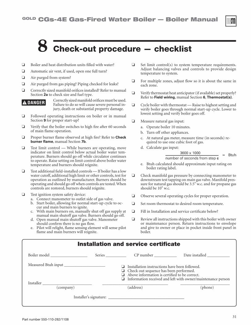
Check-out procedure — checklist8❏ Boilerandheatdistributionunitsfilledwithwater?
❏ Automaticairvent,ifused,openonefullturn?
❏ Airpurgedfromsystem?
❏ Airpurgedfromgaspiping?Pipingcheckedforleaks?
❏ Correctlysizedmanifoldorificesinstalled?RefertomanualSection2a to check size and fuel type.
Correctlysizedmanifoldorificesmustbeused.Failure to do so will cause severe personal in-jury, death or substantial property damage.
❏ Followed operating instructions on boiler or in manual Section9 for proper start-up?
❏ Verifythattheboilerswitchestohighfireafter60secondsof main flame operation.
❏ Proper burner flame observed at high fire? Refer to Check burner flame,manualSection7b.
❏ Test limit control — While burners are operating, move indicator on limit control below actual boiler water tem-perature.Burnersshouldgooffwhilecirculatorcontinuesto operate. Raise setting on limit control above boiler water temperature and burners should reignite.
❏ Test additional field-installed controls — If boiler has a low water cutoff, additional high limit or other controls, test for operationasoutlinedbymanufacturer.Burnersshouldbeoperating and should go off when controls are tested. When controls are restored, burners should reignite.
❏ Test ignition system safety device:a. Connectmanometertooutletsideofgasvalve.b. Startboiler,allowingfornormalstart-upcycletooc-
cur and main burners to ignite.c. With main burners on, manually shut off gas supply at
manualmainshutoffgasvalve.Burnersshouldgooff.d. Openmanualmainshutoffgasvalve.Manometer
should confirm there is no gas flow.e. Pilot will relight, flame sensing element will sense pilot
flame and main burners will reignite.
❏ Set limit control(s) to system temperature requirements.Adjust balancing valves and controls to provide designtemperature to system.
❏ For multiple zones, adjust flow so it is about the same in each zone.
❏ Verifythermostatheatanticipator(ifavailable)setproperly?Refer to Field wiring,manualSection6, Thermostat(s).
❏ Cycleboilerwiththermostat—Raisetohighestsettingandverify boiler goes through normal start-up cycle. Lower to lowest setting and verify boiler goes off.
❏ Measurenaturalgasinput:
a. Operate boiler 10 minutes.
b. Turn off other appliances.
c. Atnaturalgasmeter,measuretime(inseconds)re-quired to use one cubic foot of gas.
d. Calculategasinput:
e. Btuhcalculatedshouldapproximateinputratingonboiler rating label.
❏ Checkmanifoldgaspressurebyconnectingmanometertodownstreamtesttappingonmaingasvalve.Manifoldpres-sure for natural gas should be 3.5" w.c. and for propane gas should be 10" w.c.
❏ Observe several operating cycles for proper operation.
❏ Setroomthermostattodesiredroomtemperature.
❏ Fill in Installation and service certificate below?
❏ Review all instructions shipped with this boiler with owner or maintenance person. Return instructions to envelope and give to owner or place in pocket inside front panel in boiler.
Installation and service certificate
Boilermodel__________________Series__________CPnumber___________Dateinstalled___________
MeasuredBtuhinput____________________
Installer________________________________________________________________________________ (company) (address) (phone)
Installer’ssignature:_____________________________________
❏ Installation instructions have been followed.❏ Checkoutsequencehasbeenperformed.❏ Aboveinformationiscertifiedtobecorrect.❏ Information received and left with owner/maintenance person
Part number 550-110-282/110832
GOLD CGs-4E Gas-Fired Water Boiler — Boiler Manual
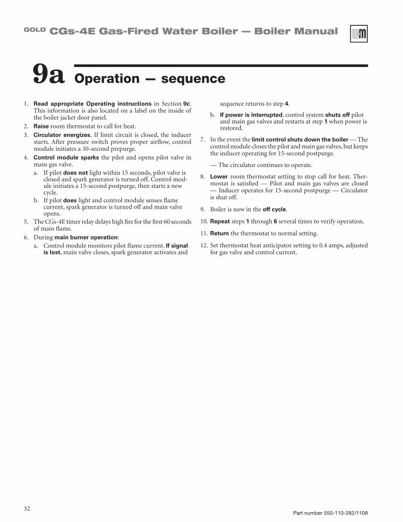
Operation — sequence9a1. Read appropriate Operating instructions in Section9c.
This information is also located on a label on the inside of the boiler jacket door panel.
2. Raise room thermostat to call for heat.3. Circulator energizes. If limit circuit is closed, the inducer
starts.After pressure switch proves proper airflow, controlmodule initiates a 30-second prepurge.
4. Control module sparks the pilot and opens pilot valve in main gas valve.a. If pilot does not light within 15 seconds, pilot valve is
closedandsparkgeneratoristurnedoff.Controlmod-ule initiates a 15-second postpurge, then starts a new cycle.
b. If pilot does light and control module senses flame current, spark generator is turned off and main valve opens.
5. TheCGs-4Etimerrelaydelayshighfireforthefirst60secondsof main flame.
6. Duringmain burner operation:a. Controlmodulemonitorspilotflamecurrent.If signal
is lost, main valve closes, spark generator activates and
sequence returns to step 4.
b. If power is interrupted, control system shuts off pilot and main gas valves and restarts at step 1 when power is restored.
7. In the event the limit control shuts down the boiler — The control module closes the pilot and main gas valves, but keeps the inducer operating for 15-second postpurge.
— The circulator continues to operate.
8. Lower room thermostat setting to stop call for heat. Ther-mostat is satisfied — Pilot and main gas valves are closed —Induceroperatesfor15-secondpostpurge—Circulatoris shut off.
9. Boilerisnowintheoff cycle.
10. Repeat steps 1 through 6 several times to verify operation.
11. Return the thermostat to normal setting.
12.Setthermostatheatanticipatorsettingto0.4amps,adjustedfor gas valve and control current.

Part number 550-110-282/110833
GOLD CGs-4E Gas-Fired Water Boiler — Boiler Manual
Operation — sequence
Figure 18 Control module sequence of operation — status light indications

Part number 550-110-282/110834
GOLD CGs-4E Gas-Fired Water Boiler — Boiler Manual
Operation — wiring diagrams9bFigure 19 Wiring diagram

Part number 550-110-282/110835
GOLD CGs-4E Gas-Fired Water Boiler — Boiler Manual
Operating instructions CGs-4E
9c • Spark pilot • Natural or propane gas
• Gas valve: Honeywell VR8204Q

Part number 550-110-282/110836
GOLD CGs-4E Gas-Fired Water Boiler — Boiler Manual
Addendum Instruction for the Commonwealth of Massachusetts
This addendum must only be used by a qualified heating installer/service technician. Read these instructions completely before beginning the installation. Failure to comply could result in severe personal injury, death or substantial property damage.
(a) For all side wall horizontally vented gas fueled equipment installed in every dwelling, building or structure used in whole or in part for residential purposes, including those ownedoroperatedby theCommonwealthandwhere theside wall exhaust vent termination is less than seven (7) feet above finished grade in the area of the venting, including but not limited to decks and porches, the following requirements shall be satisfied:
1. INSTALLATION OF CARBON MONOXIDE DETEC-TORS.Atthetimeofinstallationofthesidewallhorizon-tal vented gas fueled equipment, the installing plumber or gas fitter shall observe that a hard wired carbon monoxide detector with an alarm and battery back-up is installed on the floor level where the gas equipment is to be installed. In addition, the installing plumber or gas fitter shall observe that a battery operated or hard wired carbon monoxide detector with an alarm is installed on each additional level of the dwelling, building or struc-ture served by the side wall horizontal vented gas fueled equipment. It shall be the responsibility of the property owner to secure the services of qualified licensed profes-sionals for the installation of hard wired carbon monoxide detectors a. In the event that the side wall horizontally vented gas
fueled equipment is installed in a crawl space or an attic, the hard wired carbon monoxide detector with alarm and battery back-up may be installed on the next adjacent floor level.
b. In the event that the requirements of this subdivision can not be met at the time of completion of installa-tion, the owner shall have a period of thirty (30) days to comply with the above requirements; provided, however, that during said thirty (30) day period, a battery operated carbon monoxide detector with an alarm shall be installed.
2. APPROVED CARBON MONOXIDE DETECTORS.Eachcarbon monoxide detector as required in accordance with theaboveprovisionsshallcomplywithNFPA720andbeANSI/UL2034listedandIAScertified.
3. SIGNAGE. Ametalorplasticidentificationplateshallbe permanently mounted to the exterior of the build-ing at a minimum height of eight (8) feet above grade directly in line with the exhaust vent terminal for the horizontally vented gas fueled heating appliance or equipment. The sign shall read, in print size no less than
one-half(1/2)inchinsize,“GASVENTDIRECTLYBE-LOW.KEEPCLEAROFALLOBSTRUCTIONS.”
4. INSPECTION. The state or local gas inspector of the side wall horizontally vented gas fueled equipment shall not approve the installation unless, upon inspection, the inspector observes carbon monoxide detectors and signage installed in accordance with the provisions of 248CMR5.08(2)(a)1through4.
(b) EXEMPTIONS: The following equipment is exempt from 248CMR5.08(2)(a)1through4:1. TheequipmentlistedinChapter10entitled“Equipment
NotRequiredToBeVented”inthemostcurrenteditionofNFPA54asadoptedbytheBoard;and
2. ProductApprovedsidewallhorizontallyventedgasfueledequipment installed in a room or structure separate from the dwelling, building or structure used in whole or in part for residential purposes.
(c) MANUFACTURER REQUIREMENTS — GAS EQUIPMENT VENTING SYSTEM PROVIDED. When the manufacturer of ProductApprovedsidewallhorizontallyventedgasequip-ment provides a venting system design or venting system components with the equipment, the instructions provided by the manufacturer for installation of the equipment and the venting system shall include:1. Detailedinstructionsfortheinstallationoftheventing
system design or the venting system components; and2. A complete parts list for the venting system design or
venting system.
(d) MANUFACTURER REQUIREMENTS — GAS EQUIPMENT VENTING SYSTEM NOT PROVIDED. When the manufac-turerofaProductApprovedsidewallhorizontallyventedgasfueled equipment does not provide the parts for venting the fluegases,butidentifies“specialventingsystems”,thefollow-ing requirements shall be satisfied by the manufacturer:1. Thereferenced“specialventingsystem”instructionsshall
be included with the appliance or equipment installation instructions; and
2. The“specialventingsystems”shallbeProductApprovedbytheBoard,andtheinstructionsforthatsystemshallin-clude a parts list and detailed installation instructions.
(e)AcopyofallinstallationinstructionsforallProductApprovedside wall horizontally vented gas fueled equipment, all venting instructions, all parts lists for venting instructions, and/or all venting design instructions shall remain with the appliance or equipment at the completion of the installation.
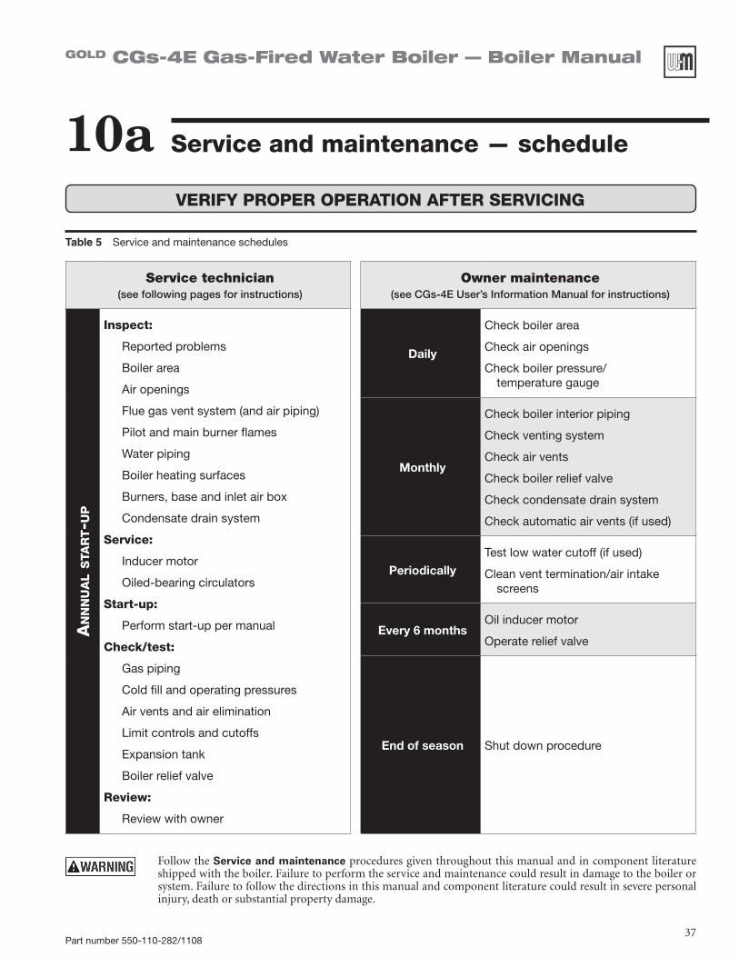
Part number 550-110-282/110837
GOLD CGs-4E Gas-Fired Water Boiler — Boiler Manual
Table 5 Service and maintenance schedules
Service technician (see following pages for instructions)
Owner maintenance (see CGs-4E User’s Information Manual for instructions)
An
nn
uA
l s
tAr
t-u
p
Inspect:
Reported problems
Boiler area
Air openings
Flue gas vent system (and air piping)
Pilot and main burner flames
Water piping
Boiler heating surfaces
Burners, base and inlet air box
Condensate drain system
Service:
Inducer motor
Oiled-bearing circulators
Start-up:
Perform start-up per manual
Check/test:
Gas piping
Cold fill and operating pressures
Air vents and air elimination
Limit controls and cutoffs
Expansion tank
Boiler relief valve
Review:
Review with owner
Daily
Check boiler area
Check air openings
Check boiler pressure/ temperature gauge
Monthly
Check boiler interior piping
Check venting system
Check air vents
Check boiler relief valve
Check condensate drain system
Check automatic air vents (if used)
PeriodicallyTest low water cutoff (if used)
Clean vent termination/air intake screens
Every 6 monthsOil inducer motor
Operate relief valve
End of season Shut down procedure
Service and maintenance — schedule10a
Follow the Service and maintenance procedures given throughout this manual and in component literature shipped with the boiler. Failure to perform the service and maintenance could result in damage to the boiler or system. Failure to follow the directions in this manual and component literature could result in severe personal injury, death or substantial property damage.
VERIFY PROPER OPERATION AFTER SERVICING

Part number 550-110-282/110838
GOLD CGs-4E Gas-Fired Water Boiler — Boiler Manual
Service & maintenance — annual start-up10bAir openings
1. Verifythatcombustionandventilationairopeningsto the boiler room and/or building are open and unobstructed.
2. Verifythatboilerventdischargeisclean and free of obstructions.
Flue gas vent system
1. Visually inspect entire flue gas venting system for blockage, deterioration or leakage. Repair any joints that show signs of leakage in accordance with vent manufacturer’s instructions. When air is ducted to boiler, verify that air inlet hose is connected and properly sealed.
Failure to inspect for the above conditions and have them repaired can result in severe personal injury or death.
Pilot and main burner flames
1. Visually inspect pilot burner and main burnerflames as directed under Start-up,Section7 of this manual.
Water piping
1. Checktheboilerinteriorpipingandallsystempip-ing for signs of leaks.
2. Repair any leaks before proceeding.
Boiler heating surfaces
1. Disconnecttheventpipeattheboilerinduceroutletconnection after turning off power to the boiler.
2. Use a bright light to inspect the flue pipe interior and inducer interior.
3. Inspect the boiler vent outlet area and heating sur-faces by looking through the opening.
4. If the vent pipe or inducer interior show evidence of soot, follow Cleaning boiler heating surfaces in this manual section to remove the flue collector and clean the boiler if necessary after close inspection of boiler heating surfaces. If there is evidence of rusty scale deposits, check the water piping and control system to make sure the boiler return water tempera-ture is properly maintained (per this manual).
5. Reconnect vent to inducer outlet and replace all boiler components before returning to service.
6. Checkinsideandaroundboilerforevidenceofanyleaks from the boiler. If found, locate source of leaks and repair.
The boiler should be inspected and started annu-ally, at the beginning of the heating season, only by a qualified service technician. In addition, the maintenance and care of the boiler designated in Table 5, page 37,and explained on the following pages must be performed to assure maximum boiler efficiency and reliability. Failure to service and main-tain the boiler and system could result in equipment failure.
Eliminate all system or boiler leaks. Continualfreshmakeupwaterwillreduceboiler life.Miner-als can build up in sections, reducing heat transfer, overheating cast iron, and causing section failure. Leaking water may also cause severe property dam-age.
Donotusepetroleum-based cleaning or sealing compounds in boiler system. Severe damage toboiler will occur, resulting in substantial property damage.
Electrical shockhazard—Turn off power to the boiler before any service operation on the boiler except as noted otherwise in this instruction manual. Failure to turn off electrical power could result in electrical shock, causing severe personal injury or death.
❏ Inspect . . .Reported problemsInspect any problems reported by owner and correct before proceeding.
Boiler area1. Verifythatboilerareaisfreeofanycombustible
materials, gasoline and other flammable vapors and liquids.
2. Verifythatboilerarea(andairintake)isfreeofanyof the contaminants listed in Table 1 on page 9 of this manual. If any of these are present in the boiler intake air vicinity, they must be removed. If they cannot be removed, isolate the boiler and provide outsidecombustionair.Seenational,provincialorlocal codes for further information.

Part number 550-110-282/110839
GOLD CGs-4E Gas-Fired Water Boiler — Boiler Manual
❏ Inspect . . .
Burners, base and inlet air box
The boiler contains ceramic fiber and fiberglass materials. Use care when handling these materials per instructions on page 64 of this manual. Failure to comply could result in severe personal injury.
If insulation is damaged or displaced, do not operate the boiler. Replace or reposition insulation as neces-sary. Failure to replace damaged insulation can result in a fire hazard, causing severe personal injury, death or substantial property damage.
1. Afterturningoffpowertotheboiler,removetheinletairboxtoppanel(Figure 27, item 13, page 56).
2. Inspect gasket (item 14). Replace if necessary.
3. Inspect burners and all other components in the inlet air box and boiler base.
4. If burners must be cleaned, first remove item 11, Figure 27, page 56. Accesstheburnerassemblybyfirstremovingburnerbaffle,item4. Then removethescrewssecuringtheburnertraytothemanifold.Slidetheburner tray out. Follow Burner cleaning instructions below to clean burners thoroughly.
5. Inspect the base insulation. Pay attention to the WARNING on page 64 regardingworkingwithinsulationmaterials.Verifythattheinsulationis intact and secure against all four sides of the base.
6. Replace all components when service has been completed.
Burner cleaning instructions
Airbornematerials,suchasfiberglassanddust,arepres-ent during construction and remodeling. These materi-als can be drawn in with the combustion air and obstruct burner ports, resulting in carbon monoxide production, a fire hazard, or building freeze damage. Read and follow the WARNING on page 9. Failure to inspect and clear gas burner ports could result in severe personal injury, death or substantial property damage.
1. Inspect each burner to insure that every port is completely open.
2. If any port is not completely clear, run a vacuum at the burner inlet while cleaning the burner ports with a wire brush. The vacuum will help to draw any airborne material out of the burner.
3. Follow instructions above to replace all components after cleaning.
Condensate drain system
1. Inspectcondensatedrainfittingsandtubing.Verifythat condensate can flow freely to drain.
❏ Service . . .
Inducer motor
1. With boiler power off,placeafewdropsofS.A.E.20 motor oil in each of the two oil cups.
Use only S.A.E. 20 motor oil to lubricatetheinducermotor.Donotuseuniversalhouseholdoils.Motorcould be damaged, resulting in pos-sible severe property damage.
Oiled-bearing circulators
1. Thecirculator shippedwith theCGs-4Eboiler iswater-lubricated.Nooilingisrequired.
2. Check other circulators in the system. Oil anycirculators requiring oil, following circulator man-ufacturer’s instructions. Over-oiling will damage the circulator.
❏ Start-up . . .
1. Performallstart-upproceduresinSection7 of this manual.
2. Verifycold fill pressure is correct and that fill system is working properly.
3. Verifyantifreeze level (if used) is at the right con-centration and that inhibitor level is correct.
4. Check gas piping,permanualSections5 and 7, verifying no indications of leakage and all piping and connections are in good condition.
5. Read the Operating instructions (Section9c of this manual or on boiler label) applying to the boiler.
6. Start theboiler following theOperating instruc-tions(Section9c of this manual or on boiler label) andmanualSection7.

Part number 550-110-282/110840
GOLD CGs-4E Gas-Fired Water Boiler — Boiler Manual
Service & maint. — annual start-up (continued)10b❏ Check/test . . .
Gas piping
1. Sniffnearfloorandaroundboilerareaforanyin-dication of a gas leak.
2. Test gas piping using bubble test,perSection5 of this manual, if there is any indication of a leak.
Cold fill and operating pressures1. While the system is cold, note the pressure reading
ontheboilerpressure/temperaturegauge.Verifythatcold fill pressure is correct.
2. Watch the pressure as the boiler and system heat up to ensure pressure rise is normal. Too high a rise would indicate a waterlogged or undersized expan-sion tank.
Air vents and air elimination1. Inspectautomaticairvents(ifused).Alsoinspect
air separators to ensure they are operational.
2. The cap must be unscrewed one turn to allow air to escape.
3. SeeFigure 22. If the air vent is leaking, remove cap A and briefly push valve B and then release to clean the valve seat.
4. Replace cap A by twisting all the way onto valve B and then unscrewing one turn.
Figure 22 Automatic air vent, typical
Limit controls and cutoffs1. Inspectandtesttheboilerlimitcontrol.Verifyop-
eration by turning control set point below boiler temperature.Boilershouldcycleoff.Returndialtooriginal setting.
2. Inspect and test additional limit controls or low water cutoffs installed on system.
Expansion tank
1. Expansiontanksprovidespaceforwatertomoveinan out as the heating system water expands due to temperature increase or contracts as the water cools. Tanks may be open, closed or diaphragm or bladder type.SeeSection3 of this manual for suggested best location of expansion tanks and air eliminators.
Open-type — located above highest radiator or baseboard unit, usually in the attic or closet. Has a gauge glass and overflow pipe to a drain.
Closed-type — welded gas tight and located above boiler. Tank is partially filled with water, leaving an air cushion for expansion.
• Makesurethistypeoftankisfittedwithatank fitting, such as the B & G Tank-Trol or Taco Taco-Trol. This fitting reduces gravity circula-tion of air-saturated tank water back to the system and prevents the air from bubbling up through the water as it returns from the sys-tem.
• Do not use automatic air vents in systems with closed-type tanks. The air will escape from the system instead of returning to the tank. Eventually,thetankwillwaterlogandnolongercontrol pressurization. The boiler relief valve will weep frequently.
Diaphragm- or bladder-type — welded gas tight with a rubber membrane to separate the tank pres-surizingairand thewater.Maybe locatedatanypoint in the system, but most often found near the boiler.
• Systemswiththistypeofexpansiontankrequireat least one automatic air vent, preferably lo-cated on top of an air eliminator, as shown in examplesinmanualSection3.
2. If relief valve has tended to weep frequently, the ex-pansion tank may be waterlogged or undersized.
Closed-type tank — tank is most likely water-logged. Install a tank fitting if not already installed. Then check fill level per fitting manufacturer’s instructions. If fill level is correct, check tank size against manufacturer’s instructions. Replace with a larger tank if necessary.
Diaphragm- or bladder-type — first, check tank size to be sure it is large enough for the system. If size is too small, add additional tank(s) as neces-sary to provide sufficient expansion. If tank size is large enough, remove tank from system and check charge pressure (usually 12 psig for residential ap-plications). If tank won’t hold pressure, membrane has been damaged. Replace tank.

Part number 550-110-282/110841
GOLD CGs-4E Gas-Fired Water Boiler — Boiler Manual
Safetyreliefvalvesshouldbereinspected AT LEAST ONCE EVERY THREE YEARS, by a licensed plumbing contractor or authorized inspection agency, to ensure that the product has not been affected by corrosive water conditions and to ensure that the valve and discharge linehavenotbeenalteredortamperedwithillegally.Certainnaturallyoccurring conditions may corrode the valve or its components over time,renderingthevalveinoperative.Suchconditionsarenotdetect-able unless the valve and its components are physically removed and inspected. This inspection must only be conducted by a plumbing contractor or authorized inspection agency — not by the owner. Failure to reinspect the boiler relief valve as directed could result in unsafe pressure buildup, which can result in severe personal injury, death or substantial property damage.
Following installation, the valve lever must be operated AT LEAST ONCE A YEARtoensurethatwaterwaysareclear.Certainnaturallyoccurring mineral deposits may adhere to the valve, rendering it inop-erative. When manually operating the lever, water will discharge and precautions must be taken to avoid contact with hot water and to avoid waterdamage.Beforeoperating lever,checktoseethatadischargeline is connected to this valve directing the flow of hot water from the valve to a proper place of disposal otherwise severe personal injury may result. If no water flows, valve is inoperative.Shutdownboileruntil a new relief valve has been installed.
Boiler relief valve1. Inspect the relief valve and lift the lever to verify flow as in the following warnings,
excerptedfromareliefvalvemanufacturer’swarninglabel.Beforeoperatinganyre-lief valve, ensure that it is piped with its discharge in a safe area to avoid severe scald potential.ReadmanualSection3 before proceeding further.
2. Afterfollowingtheabovewarningdirections,ifthereliefvalveweepsorwillnotseatproperly,replacethereliefvalve.Ensurethatthereasonforreliefvalveweepingisthevalve and not over-pressurization of the system due to expansion tank waterlogging or undersizing.
Figure 23 Relief valve, typical

Part number 550-110-282/110842
GOLD CGs-4E Gas-Fired Water Boiler — Boiler Manual
Service & maint. — annual start-up10b❏ Review with owner1. Review the User’s Information Manual with the
owner.2. Emphasize theneed toperform themaintenance
schedule specified in the User’s Information Manual (and in this manual as well).
3. Remind the owner of the need to call in a licensed contractor should the boiler or system exhibit any unusual behavior.
4. Remind the owner to follow the proper shutdown procedure and to schedule an annual start-up at the beginning of the next heating season.
❏ Cleaning boiler heating surfaces
The boiler contains ceramic fiber and fiberglass materials. Use care when handling these materials per instructions on page 64 of this manual. Failure to comply could result in severe personal injury.
1. Shutdownboiler:• Follow“To Turn Off Gas to Appliance”
instructions on boiler and Operating instruc-tions.
• Donotdrainboilerunlessitwillbeexposedto freezing temperatures. If using antifreeze in system, do not drain.
2. Follow shutdown procedure.
3. Remove venting system connection to boiler.
4. Remove top jacket panel. Turn back insulation.
5. Remove collector box/transition assembly. Cleansealant from assembly and sections.
6. Remove radiation plates hanging between sec-tions.
7. Remove burners from base. Brush and vacuumburnerstoremovealldustandlint.Verifythatallburner ports are free of debris.
8. Place newspapers in base of boiler to collect soot.
9. Cleanbetweensectionswithwirefluebrush.
10.Removenewspaperandsoot.Vacuumorbrushbaseand surrounding area.
11. Reinstall radiation plates.
12.Replacecollectorbox/transitionassembly.Sealwithsealant. Obtain gas-tight seal to prevent flue gas spillage and carbon monoxide emissions, resulting in severe personal injury or death.
13. Replace insulation and jacket top panel.
14.StartupboilerfollowingSection7 of this manual and the boiler Operating instructions(Section9c of this manual). Excessive sooting indicates im-proper gas combustion. If found, check for proper combustion and make any necessary adjustments.

Part number 550-110-282/110843
GOLD CGs-4E Gas-Fired Water Boiler — Boiler Manual
Troubleshooting — procedure11a Label all wires prior to disconnection when servicing controls. Wiring
errors can cause improper and dangerous operation. Never jumper (bypass) rollout thermal fuse element or any other
device except for momentary testing as outlined in Troubleshooting Charts.Severepersonalinjury,deathorsubstantialpropertydamagecan result.
Before troubleshooting:1. Have the following items:
a. Voltmeter that can check 120 VAC and 24 VAC.b. Microammeter with a minimum scale range of 0-25.c. Continuity checker.d. U-tube manometer.
2. Check for 120 VAC (minimum 102 VAC to maximum 132 VAC) to boiler.
3. Make sure thermostat is calling for heat and contacts (including appropriate zone controls) are closed. Check for 24 VAC between thermostat wire nuts and ground.
Check the following:1. Wire connectors to control module are securely plugged in at module and originating control.
2. Air pressure switch hoses are properly and securely plugged in and are not damaged.
3. Verify gas supply pressure:
a. With boiler OFF — 13” w.c. maximum natural or propane gas pressure upstream of gas valve.
b. With boiler ON — Upstream: 5” w.c. minimum natural gas pressure or 11” w.c. propane gas pressure upstream of gas valve.
4. Verify gas manifold pressure (downstream of gas valve):a. Natural gas:
Manifold pressure, high fire: 3.50” w.c. Manifold pressure, low fire: 0.90” w.c. while in low fire at start-up (60 seconds)b. Propane gas:
Manifold pressure, high fire: 10.0” w.c. Manifold pressure, low fire: 3.50” w.c. while in low fire at start-up (60 seconds)c. If necessary, adjust gas pressure on the gas valve as shown below. After adjustments, refer
to page 29 to check the flame.
High-fire gas pressure adjustment
Low-fire gas pressure adjustment
Honeywell VR8204Q two-stage gas valve

Part number 550-110-282/110844
GOLD CGs-4E Gas-Fired Water Boiler — Boiler Manual
Troubleshooting — air pressure switch11bAir pressure switch
Makesureboilerwatertemperatureis 100°F or cooler before startingprocedure to obtain appropriate readings.
Check pressure switch setting1. SeeFigure 24 and Table 6.
2. Remove both air pressure switch hoses from air pressure switch.
3. Install tees and tubing as shown in Figure 24 to inclined manometer.
4. Turn off gas valve and set thermostat to call for heat. Inducer will run but burners will not ignite.
5. Checkfor24VACbetweenbothairpressureswitchterminals and ground.
6. If manometer reading is above the setpoint of the switch (see Table 6),butthereisnot24VACbetweenboth air pressure switch terminals and ground — replace air pressure switch.
Figure 24 Manometer connections
Table 6 Pressure switch setpoint (for elevations above 2,000 ft, contact your local Weil-McLain sales office for details.)
Boiler model number Inches W.C.
CGs-4E 1.71”
Troubleshooting air pressure reading1. If manometer reading is lower than the setpoint
of the switch (see Table 6) — check for possible causes:• blockageinhoses• obstructionininducerhousingoutlet• looseinducerwheelonmotorshaft• inducermotornotinproperrpm• inducerbackplatenotsealedproperly• blockageinblockassembly• blockageinfluepipeortermination• incorrectpressureswitch
Return to normal operationWhen pressure reading is correct and air pressure switch is operating properly — remove tees and reinstall hoses to air pressure switch.
The boiler will not operate correctly unless pressure switch hoses are correctly located. The red hose connects from the right side (negative) hose barb to the flue collector. The white hose connects from the left side (positive) hose barb of the switch to the connector box (between flue collector and inducer) as shown in Figure 24.

Part number 550-110-282/110845
GOLD CGs-4E Gas-Fired Water Boiler — Boiler Manual
Troubleshooting — control module11cControl module
Solder or water splatter between plugs and circuit board can cause improper operation of control module. Place a shield over the boiler internal controls and components during installation. Failure to comply could result in severe personal injury, death or substantial property damage.
Make sure ground wiring is installed per wiring diagram.Goodgroundingisextremelyimportantforproper operation.
Control indicator lights — LOCKOUT modesSeeCharts 1 through 7inthisSectionfordetailedtrouble-shooting procedures.
Toresetcontrolafteralockout,turnoffpoweratthe120VACservice switch or turn down all thermostats. Wait 45 seconds. Then restore power or call for heat.
POWER light flashing alone
Usuallyindicatesreversedpolarityof120VACpowerwires.
POWER and TSTAT CIRC lights flashing
Usually indicates stray voltage on external thermostat circuit wires (usually due to miswired 3-wire zone valve).
POWER and PRESS SWITCH lights flashing
Usually indicates pressure switch is closed when it should not be, or pressure switch failed to close within 5 minutes of inducer starting.
POWER and FLAME lights flashing
Usually indicates false flame sense or flame sensed when it shouldn’t be there.
Control indicator lights — NON-LOCKOUT modes
POWER light on and FLAME light flashing
Usually indicates pilot flame was not established within 15 secondsfromapplicationofspark.Controlwillflashlight,butwill continue to cycle indefinitely until flame is established or problem is corrected.
POWER light on and PRESS SWITCH light flashing
Usually indicates pressure switch opened during the run cycle.
Troubleshooting the control module
SeeFigure 25, page 46, for location of harness plug receptacles and plugs on the control module.

Part number 550-110-282/110846
GOLD CGs-4E Gas-Fired Water Boiler — Boiler Manual
Troubleshooting — control module (continued)11cFigure 25 Control module connections

Part number 550-110-282/110847
GOLD CGs-4E Gas-Fired Water Boiler — Boiler Manual
Troubleshooting — control module lights11dCHART 1 — Troubleshooting POWER light status
Electrical shock hazard — Wherever you see TURN OFF POWER, follow the instructions. Failure to follow instructions could result in severe personal injury, death or substantial property damage.
Problem is with incoming electricity. Have licensed electrician repair circuit.
Replace control module. Retest.
Boiler should now operate normally.
Have system checked by a licensed electrician. If problem persists, call your local Weil-McLain sales representative.
• Make sure service switch or circuit breaker is on or fuses are good.
• Remove 120 VAC IN plug (Figure 25, Item 3, page 46) on control module.
• Using voltmeter, check across top and bottom pins of 120 VAC IN plug.
Does voltmeter indicate 120 VAC?
No Yes
No Yes
No Yes
Chart 2
Chart 6
TSTAT CIRClight flashing
Chart 3
Chart 4
PRESS SWITCHlight flashing
FLAMElight flashing
For insufficient heat or no heat problem, go to Chart 7 if POWER light is on steady, with no other light flashing.
No Yes
On steady(not flashing)
No Yes
— Usually indicates reversed 120 VAC polarity if POWER light flashes by itself —
Is POWER light off?
Is POWER light ...
Flashingalone
Flashing with another light
• Reconnect 120 VAC IN plug.• Remove 120 VAC IN transformer PRIMARY plug
(Figure 25, Item 3, page 46) on control module.• Using voltmeter, check across top and bottom pins of
PRIMARY receptacle.
Does voltmeter indicate 120 VAC?
• Reinstall 120 VAC transformer PRIMARY plug.• Remove 24 VAC transformer plug (Figure 25, Item 3,
page 46) on control module.• Using voltmeter, check pins of plug.
Does voltmeter indicate 24 VAC?
Replace control module. Retest.
Replace transformer. Retest and check for back feed of voltage from system wiring.
• Usually indicates polarity on incoming 120 VAC power line is wrong.
• TURN OFF POWER at service switch or breaker, then reverse the HOT and NEUTRAL wires entering the boiler in the J-box.
• Restore POWER at service switch or breaker.
Is POWER light flashing now?
Chart 5

Part number 550-110-282/110848
GOLD CGs-4E Gas-Fired Water Boiler — Boiler Manual
Troubleshooting — control module lights11d
Electrical shock hazard — Wherever you see TURN OFF POWER, follow the instructions. Failure to follow instructions could result in severe personal injury, death or substantial property damage.
CHART 2 — TSTAT CIRC & POWER lights flashing
No Yes
Did you find a voltage across the two external thermostat circuit wires?NoYes
• Leave external boiler thermostat connection wires disconnected from boiler.
• Troubleshoot the external thermostat circuit until you find the source of the stray voltage. (Pay close attention to the wiring connections to 3-wire zone valves.)
• Correct the problem and repeat the voltmeter test above, verifying there is no longer a voltage reading under any condition in the external thermostat circuit.
• An isolating relay may be required.
• Disconnect the two external wires connected to the boiler thermostat leads (two black low voltage leads in J-box).
• Connect a voltmeter across these two incoming wires. Close each thermostat, zone valve and relay in the external circuit one at a time and check the voltmeter reading across the wires.
• There should NEVER be a voltage reading.
• If a voltage does occur under any condition, check and correct the external wiring. (This is a common problem when using 3-wire zone valves.)
• Once the external thermostat circuit wiring is checked and corrected if necessary, reconnect the external thermostat circuit wires to the boiler thermostat wires and allow the boiler to cycle.
• Boiler should now operate per the normal sequence of operation shown in Figure 18, page 33.
• If no voltage is found under any condition of the external thermostat circuit, connect the two boiler thermostat connection leads together (or jumper the boiler aquastat T-T terminals).
• Turn off power to the boiler for 1 minute.
• Turn on power and allow boiler to cycle.
Do the TSTAT and POWER lights still flash?
• Replace control module.• Retest.
— Usually indicates 48 VAC on thermostat circuit (stray voltage) —

Part number 550-110-282/110849
GOLD CGs-4E Gas-Fired Water Boiler — Boiler Manual
Troubleshooting — control module lights (cont.)11dCHART 3 — PRESS SWITCH & POWER lights flashing
Electrical shock hazard — Wherever you see TURN OFF POWER, follow the instructions. Failure to follow instructions could result in severe personal injury, death or substantial property damage.
• Boiler should be in normal operating sequence.
• Observe operation until thermostat is satisfied and inducer has completed its post-purge cycle.• Remove one of the wires connected to the pressure
switch.• Check continuity across the switch terminals.
Does the ohmmeter indicate the switch is closed?
• Replace control module.
• Retest.
• Check air pressure switch per manual Section 11b.
• Replace if necessary.• Retest.
• Try reseating plug in module receptacle and restart.
• If inducer still does not work, replace inducer assembly.
• Retest.
No Yes
• Wait 45 seconds.Does inducer motor operate?
No Yes
• Remove INDUCER plug (Figure 25, Item 6, page 46) from plug receptacle of control module.
• Place voltmeter leads across the 120 VAC N and 120 VAC H pins of the INDUCER receptacle (left column center and right column bottom pins).
Does the voltmeter indicate 120 VAC?
No Yes
Are vent or combustion air passages blocked?
No Yes
• Clear passages and recycle boiler.
• Recheck boiler operation.
No Yes
• Reset boiler control by turning off power at service switch or turning down thermostat for at least 45 seconds.• Thermostat should call for heat and appropriate zone valves open.
Does inducer motor operate?
No Yes
— Usually indicates pressure switch stuck closed or failed to make within 5 minutes —
• Wait 5 minutes.Is PRESS SWITCH light flashing?

Part number 550-110-282/110850
GOLD CGs-4E Gas-Fired Water Boiler — Boiler Manual
11d Troubleshooting — control module lights (cont.)
• Turn off power to the boiler at service switch or breaker.• Wait at least 45 seconds.• Turn on power to boiler.• Restart boiler, following Operating instructions in this
manual (Section 9c).• Look through the pilot inspection port (in front of air inlet
box) to see if the pilot is burning during the prepurge period (first 30 seconds of operation).
Is pilot burning during prepurge period?
CHART 4 — FLAME & POWER lights flashing
Electrical shock hazard — Wherever you see TURN OFF POWER, follow the instructions. Failure to follow instructions could result in severe personal injury, death or substantial property damage.
• Leave main manual gas valve closed.• Turn off power to boiler at service switch or breaker.• Wait at least 45 seconds.• Turn on power to boiler.• Restart boiler, following Operating instructions in this
manual (Section 9c).Do FLAME and POWER lights still flash?
• Boiler should now operate normally.
• Original flashing FLAME light caused by gas valve not operating properly.
• See normal sequence of operation,Figure 18,page 33.
• Replace gas valve.• Retest boiler.
Are FLAME and POWER lights flashing?
No Yes
No Yes
Are manual main shutoff valve and gas valve open?
• Replace control module.• Retest.
— Usually indicates flame sensed when it shouldn't be there —
YesNo
• TURN OFF POWERto boiler at service switch or breaker.
• Open main manual gas valve.
• Turn on power to boiler at service switch or breaker.
• Restart boiler per lighting instructions.
• Perform start-up procedures in boiler manual to verify proper operation.
• Allow boiler to continue cycling.Are FLAME & POWER lights flashing?
No Yes No Yes
• Replace control module.
• Retest.
• Replace control module.
• Retest.
• Boiler may now be operating normally.
• Perform start-up procedures in boiler manual to verify proper operation.

Part number 550-110-282/110851
GOLD CGs-4E Gas-Fired Water Boiler — Boiler Manual
Troubleshooting — control module lights (cont.)11dCHART 5 — PRESS SWITCH light flashing and POWER light on steady
Electrical shock hazard — Wherever you see TURN OFF POWER, follow the instructions. Failure to follow instructions could result in severe personal injury, death or substantial property damage.
— Usually indicates pressure switch opened during run cycle —— May also be caused by wind gusts in excess of 31 mph for non-direct vent sidewall-vented boilers —
• Boiler should be in normal operating sequence.
• Observe operation until thermostat is satisfied and inducer has completed its post-purge cycle.
• Remove one of the wires connected to the pressure switch.
• Check continuity across the switch terminals.Does the ohmmeter indicate the switch is closed?
• Inspect and check wire harness from control module to pressure switch.
• Reseat connector in control module receptacle.
• If harness is intact and properly seated, but problem persists, replace control module.
• Retest.
• Check air pressure switch per manual Section 11.• Replace if necessary. Retest.
• Replace inducer assembly.
• Retest.
No Yes
• Remove INDUCER plug (Figure 25, Item 6, page 46) from plug receptacle of control module.
• Place voltmeter leads across the 120 VAC N and 120 VAC H pins of the INDUCER receptacle (left column center and right column bottom pins).
Does the voltmeter indicate 120 VAC?
No Yes
Are vent or combustion air passages blocked?
No Yes
• Clear passages and recycle boiler.
• Recheck boiler operation.
• Reset boiler control by turning off power at service switch or turning down thermostat for at least 45 seconds.• Thermostat should call for heat and appropriate zone valves open.
Does blower motor operate?
No Yes
No Yes
• Wait 5 minutes.Is PRESS SWITCH light flashing?

Part number 550-110-282/110852
GOLD CGs-4E Gas-Fired Water Boiler — Boiler Manual
11d Troubleshooting — control module lights (cont.)
• TURN OFF POWERto boiler at service switch or
breaker.• Remove burner shield (see
Figure 27, page 56 for location).
• Verify inlet gas pressure at gas valve:
Natural gas — 5.0" w.c. min/14.0" w.c. max
Propane — 11.0" w.c. min/14.0" w.c. max
Is gas present at gas valve inlet and within above range?
CHART 6 — FLAME light flashing and POWER light on steady
ALSO — Troubleshooting failure to establish main flame
Electrical shock hazard — Wherever you see TURN OFF POWER, follow the instructions. Failure to follow instructions could result in severe personal injury, death or substantial property damage.
No Yes
• Is pilot flame visible through inspection port?• Are main manual shutoff valve and boiler gas valve open?
No Yes
• TURN OFF POWER to boiler at service switch or breaker.• Open main manual shutoff valve and boiler gas valve (per
Operating instructions in this manual).• Turn on power at service switch or breaker. A
Does FLAME light flash now?
No Yes
• Boiler should be in normal operating sequence.
• Observe operation until thermostat is satisfied and blower has completed its post-purge cycle.
• Make sure ground wire terminal is securely fastened to control module mounting screw.
• Check the voltage across terminals PV and C of the gas valve.
Is 24 VAC present there?NoYes
• Check the voltage across terminals MV and C of the gas valve.
Is 24 VAC present there?No Yes
No
Yes• Contact gas supplier to correct pressure or gas supply.
• If the wiring from the control module to gas valve is intact, replace the control module.
• Retest.
• TURN OFF POWER to boiler at service switch or breaker.• Check flame signal — Detach sense lead from ignition control
(Figure 25, item 8, page 46).• Connect negative lead of MICROAMMETER to control sense
terminal (Figure 25, item 8, page 46). Connect positive lead of MICROAMMETER to sense wire.
• DISCONNECT red wire connected to terminal MV of the gas valve.
• Turn on power to boiler and allow to cycle. As soon as pilot is burning, the MICROAMMETER should read at least 1.0 microamp.
Is flame signal at least 1.0 microamp?No Yes
• If the wiring from the control module to gas valve is intact, replace the control module and retest.
• Verify inlet gas pressure at gas valve:
Natural gas — 5.0" w.c. min/14.0" w.c. max
Propane — 11.0" w.c. min/14.0" w.c. max
Is gas present at gas valve inlet and within above range?
No
Yes
• TURN OFF POWERto boiler at service switch or breaker.
• Remove air inlet box top (see Figure 27, page 56 for location).
• Verify pilot gas line is not kinked, obstructed or damaged and is correctly attached to pilot and gas valve.
• Verify pilot ignition electrode, electrode ceramic and spark lead wire from control are in good condition. Spark gap should be approximately 1/8".
• Correct any above problems, replacing pilot if burner or wiring is damaged.
• Reinstall burner shield to operate boiler for retest after any changes or corrections.
• If none of the above corrects problem, then replace the control module, reinstall air inlet box top, and retest.
• Verify pilot burner is securely attached to pilot bracket, bracket is securely attached to cross tie, and there is no corrosion on the parts which would affect the ground path for flame sense.
• Verify that pilot flame rod, flame rod ceramic and lead wire from control module to flame rod are in good condition.
• Correct any above problems, replacing pilot if burner or wiring is damaged.
• If none of the previous steps (including replacing pilot) corrects problem, then replace the control module, reinstall burner shield and retest.

Part number 550-110-282/110853
GOLD CGs-4E Gas-Fired Water Boiler — Boiler Manual
Troubleshooting — control module lights (cont.)11dCHART 7 — Insufficient heat or no heat to system (POWER light on steady)
Electrical shock hazard — Wherever you see TURN OFF POWER, follow the instructions. Failure to follow instructions could result in severe personal injury, death or substantial property damage.
• Replace rollout switch.
• Boiler is in standby.• Set thermostat to call for
heat and recheck operation.
• Verify Sequence of operation, Figure 18, page 33.
Replace control module. Retest.
•
Figure 18, page 33• Also check setting on limit switch (should
be above 140°F.).
• Has it been at least 5 minutes since setting thermostat to call for heat? If not, wait 5 minutes. Is system heating?
• Is thermostat set to call for heat? Remove thermostat wires at boiler and check continuity across the two wires. If circuit isn't closed, check external thermostat (zone valve, relay, etc.) wiring. Correct problems and retry.
• Reconnect external thermostat wiring at boiler.Is thermostat circuit closed (continuity across wires)?
• If you have sufficient heat — boiler should be in normal operating sequence. (See normal sequence of operation, Figure 18, page 33.)
• If you have less than sufficient heat —Are vent and combustion air piping free of blockage?
No Yes
• Correct conditions and recheck operation.
• See Figure 18, page 33 for normal sequence of operation.
• Check heat loss calculation versus boiler size.
• Clock gas input.
• Replace control module.
• Retest.
• Repair/replace circulator. Retest.
• Repair/replace wiring. Retest.
• Remove CIRCULATOR harness plug from CIRCULATOR plug receptacle (Figure 25, Item 7, page 46). Check with voltmeter across pins of control module receptacle.
Does voltmeter show 120 VAC across pins?
No Yes
Is boiler System circulator operating?
• Wait 5 minutes.Is FLAME light on?
NoYes
• Wait for boiler water to cool to temperature 20 to 30 °F lower than temperature set on limit switch.
Are limit switch contacts closed?
Is LIMIT light on?
No Yes
Are all red lights off?No Yes
Wait 30 seconds.Are all red lights off?
No Yes
• Replace control module.• Retest.
• Check limit switch contacts with continuity checker.Are limit switch contacts
closed?No Yes
No Yes
No Yes
• Replace limit switch.
• Retest.
No Yes
Check rollout switch continuity — is switch
closed?
No Yes
• Check any other limit controls wired into the limit circuit. If all are OK, then replace control module.
• Retest.
If rollout thermal fuse element has opened, determine cause and correct condition. Failure to do so will cause severe personal injury, death or substantial property damage.
NoYes
Is manifold pressure:3.50" w.c. on natural gas? 10.0" w.c. on propane?
• Replace timer relay.

Part number 550-110-282/110854
GOLD CGs-4E Gas-Fired Water Boiler — Boiler Manual
Replacement parts12aSection assembly .............................................. 55
Base .................................................................. 56
Jacket ............................................................... 58
Trim .................................................................. 60
Controls ............................................................ 61
Replacement parts must be purchased through a localWeil-McLain
distributor. When ordering, specify boiler model and size and include
description and part number of replacement part. Results from using
modified or other manufactured parts will not be covered by warranty
and may damage boiler or impair operation.
Weil-McLain part numbers are found in Weil-McLain Boilers and
Controls Repair Parts Lists.
The boiler contains ceramic fiber and fiberglass materials. Use care when handling these materials per instructions on page 64 of this manual. Failure to comply could result in severe personal injury.

Part number 550-110-282/110855
GOLD CGs-4E Gas-Fired Water Boiler — Boiler Manual
Replacement parts — section assembly12bFigure 26 Section assembly
Item number Description Weil-McLain part number
1 End section, left hand, 51124 311-103-850
2 End section, right hand 51128 311-103-821
3 Intermediate section, 51125 311-103-818
not shown Replacement section assembly CGs-4E 321-114-346
not shown Section replacement kit, includes seals and sealant for 1 joint 381-354-527
4 Tie rod, M\zn” without nut (3 per boiler): CGs-4E 560-234-501
5 Nut, M\zn” (2 per tie rod) 561-928-235
6 Washer, M\zn” (1 per tie rod) 562-248-684
7 Radiation plate (1 per joint) 460-003-700
8 Collector hood and transition assembly CGs-4E 381-354-601
9 High limit, 30° differential, with well Honeywell L4080D1036White-Rodgers 11B81-3
510-312-250
10 Inducer fan assembly kit, includes inducer fan assembly, gasket and nuts 381-356-499
11 Gasket, inducer 590-317-627

Part number 550-110-282/110856
GOLD CGs-4E Gas-Fired Water Boiler — Boiler Manual
Replacement parts — base12cFigure 27 Base assembly

Part number 550-110-282/110857
GOLD CGs-4E Gas-Fired Water Boiler — Boiler Manual
Replacement parts — base (continued)12cItem Description Weil-McLain
part number
Base insulation kit(includes insulation for all base parts above plus gasket material needed between block assembly and base)
CGs-4E 381-356-516
Base assembly kit(includes base panels items 1, 2, 3, 4, 5, 6, 7, 8, 11,13, 22 and 23 plus insulation, Air box gaskets, and hardware)
CGs-4E 381-356-523
Inlet air box top panel kit(includes items 13 and 14)
CGs-4E 381-356-502
Inlet air box front panel kit(includes items 11, 12 and 23)
CGs-4E 381-356-509
1 Base pan (in Base assembly)
2 Boiler leg kit 550-320-219
3 Heat shield (in Base assembly)
4 Burner baffle (in Base assembly)
5 Base left side panel (in Base assembly)
6 Base right side panel (in Base assembly)
7 Base back panel (in Base assembly)
8 Base front cross-tie assembly (in Base assembly)
9 Pilot bracket 450-003-689
10 Pilot burner assembly — Natural gasPilot burner assembly — Propane gas
511-330-080511-330-081
11 Inlet air box front panel (in Inlet air box front panel kit)
12 Inlet air box front panel gasket (Use Gasket kit)
13 Inlet air box top panel (in Inlet air box top panel kit)
14 Inlet air box top panel gasket (Use Gasket kit)
15 Manifold (per size) CGs-4E 591-126-723
16 Manifold mounting gasket 590-317-406
17 Burner mounting panel CGs-4E 450-003-691
18 Rear spacer strip CGs-4E 550-320-161
19 Burner 512-200-076
20 Burner orifice — Natural gas, sea level, CGs-4EBurner orifice — Propane gas, sea level, CGs-4E
560-529-126560-529-111
21 Thermal fuse element 512-050-230
22 Grommet for sealing pilot tubing/wiring opening to Air box 591-850-064
23 Inspection port clear plug 591-491-216
24 Hex nut for burner end stud, 5 mm 550-320-170
Gasket (for Air inlet box covers), 8-foot length 590-317-400

Part number 550-110-282/110858
GOLD CGs-4E Gas-Fired Water Boiler — Boiler Manual
Replacement parts — jacket12dFigure 28 Jacket assembly

Part number 550-110-282/110859
GOLD CGs-4E Gas-Fired Water Boiler — Boiler Manual
Replacement parts — jacket (continued)12d
Boiler Model
1 2 3 4 5 6
Boiler ModelJunction box,
2 x 4
Panel, left side, with insulation Panel, right
side, with insulation
Panel, top front, with insulation
Panel, top rear, with insulation
Panel, door
Natural Gas Propane Gas
CGs-4E(Available at local
supply house)381-355-794 381-355-796 381-355-614 381-355-413 381-355-713 381-355-795 CGs-4E
Boiler Model
7 8 9 10 11 12 Not shown
Boiler ModelCross tie,
bottom frontPanel, interior, with insulation
Panel, rear, with insulation
Air inlet fitting
Inlet air hose
Hose clamp 3”
Gold touch-up paint
CGs-4E 431-223-326 381-355-422 431-223-302 560-907-635 562-302-573 591-850-068 592-000-000 CGs-4E

Part number 550-110-282/110860
GOLD CGs-4E Gas-Fired Water Boiler — Boiler Manual
Replacement parts — trim12eFigure 29 Trim assembly
Itemnumber
Description Manufacturer Manufacturer’s part number
Weil-McLainpart number
1 Pressure relief valve, ASME, 30 PSIG, ¾” male inlet
Pressure relief valve, ASME, 30 PSIG, ¾” female inlet (Fittings shown are factory-installed on boiler.)
ConbracoWatts
ConbracoWatts
10-407-10M330
10-408-05335
511-546-920
511-546-924
2 Combination pressure-temperature gauge, 3Z\,” diameter, short shank (Fittings shown are shipped loose with boiler.)
Weil-McLain 380-000-000
3 Drain valve, ¾” (Fittings shown are included with boiler.)
ConbracoHammond
ValveMatco-Norca
Watts
31-606-01710
205F04BD-2C
511-210-423511-246-392
511-246-392511-246-392
4 Circulator (Fittings shown are shipped loose with boiler.)
Bell & GossettGrundfos
Taco
NRF-22-103253UP15-42FR-TB4
007
511-405-118511-405-126511-405-113
5 Circulator gasket, universal (2 per boiler) Weil-McLain 590-317-535
not shown
Circulator hardware kit, includes: 1 flange, 2 nuts, 2 screws, 1 gasket — 1” NPT — CGs-4E
Weil-McLain
381-354-525
6 Circulator wiring harness kit, with Molex (loose) 381-354-528
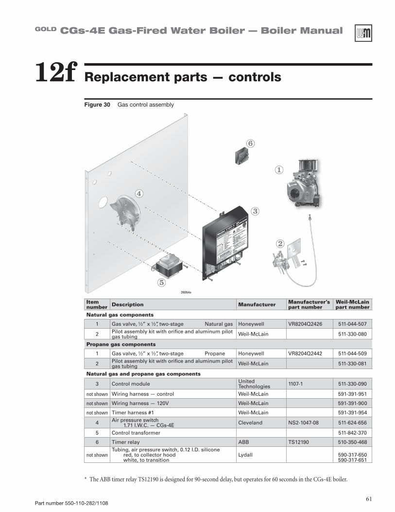
Part number 550-110-282/110861
GOLD CGs-4E Gas-Fired Water Boiler — Boiler Manual
Replacement parts — controls12fFigure 30 Gas control assembly
Itemnumber Description Manufacturer Manufacturer’s
part numberWeil-McLainpart number
Natural gas components
1 Gas valve, ½” x ½”, two-stage Natural gas Honeywell VR8204Q2426 511-044-507
2 Pilot assembly kit with orifice and aluminum pilot gas tubing Weil-McLain 511-330-080
Propane gas components
1 Gas valve, ½” x ½”, two-stage Propane Honeywell VR8204Q2442 511-044-509
2 Pilot assembly kit with orifice and aluminum pilot gas tubing Weil-McLain 511-330-081
Natural gas and propane gas components
3 Control module United Technologies 1107-1 511-330-090
not shown Wiring harness — control Weil-McLain 591-391-951
not shown Wiring harness — 120V Weil-McLain 591-391-900
not shown Timer harness #1 Weil-McLain 591-391-954
4 Air pressure switch1.71 I.W.C. — CGs-4E Cleveland NS2-1047-08 511-624-656
5 Control transformer 511-842-370
6 Timer relay ABB TS12190 510-350-468
not shownTubing, air pressure switch, 0.12 I.D. silicone
red, to collector hoodwhite, to transition
Lydall 590-317-650590-317-651
*TheABBtimerrelayTS12190isdesignedfor90-seconddelay,butoperatesfor60secondsintheCGs-4Eboiler.

Part number 550-110-282/110862
GOLD CGs-4E Gas-Fired Water Boiler — Boiler Manual
Dimensions13aFigure 31 Dimensional drawing
Boilermodelnumber
Supplytapping
(inches NPT)
Returntapping
(inches NPT)
Gasconnection size
Note 3 (inches NPT)
Gasmanifold size
Note 3 (inches NPT)
“A”Air inlet
pipe center (inches)
“W”Jacket width
(inches)
CGs-4E 1 ¼ 1 ¼ ½ ½ 8 16
Note 3: Gas piping from meter to boiler to be sized per local utility requirements.

Part number 550-110-282/110863
GOLD CGs-4E Gas-Fired Water Boiler — Boiler Manual
Ratings
Table 7 Boiler ratings
DOE
13b
(Note5)
CGs-4Eboilersusedforresidentialradiantpanelsystems,convertedgravityheatingsystemsorotherlowwatertemperature applications should be installed with balancing valves and bypass piping equal to the supply and return size to avoid excessive flue gas condensation due to lower operating water temperatures. For alternate piping,contactyourWeil-McLainsalesoffice.CSAdesigncertifiedforinstallationoncombustibleflooring.Tested for 50 psi working pressure.
Boiler model number
DOEHeating capacity
(Btuh)
0-2,000 feet 2,000-4,500 feet NetI=B=Rratings(Btuh)
Boiler water
content (gallons)
DOESeasonal efficiency(% AFUE)
Ventsize
Input(Btuh)
Output (Btuh)
Input(Btuh)
Output (Btuh)
(Note 1) (Note 2) (Note 3) (Note 5) (Note 4)
CGs-4E(Note 5)
77,000 90,000 77,000 81,000 69,300 67,000 2.1 85.0 3”
Notes
1. Add “PIN” for natural gas boiler - “PIL” for propane gas boiler.
2. Based on standard test procedures prescribed by the United States Department of Energy.
3. Net I=B=R ratings are based on net installed radiation of sufficient quantity for the requirements of the building and nothing need be added for normal piping and pickup. Ratings are based on a piping and pickup allowance of 1.15. An additional allowance should be made for unusual piping and pickup loads.
4. The CGs-4E boiler requires special venting, consistent with Category IV boiler. Use only the vent materials and methods specified in CGs vent supplements. The CGs-4E boiler MUST be direct-vented (using 3” diameter air piping) as specified in the direct vent supplements.
5. As an Energy Star Partner, Weil-McLain has determined that the CGs-4E meets the Energy Star guidelines for energy efficiency.

64Part Number 550-110-282/1108
GOLD CGs-4E Gas-Fired Water Boiler — Boiler Manual
Handling ceramic fiber and fiberglass materials
REMOVAL OF COMBUSTION CHAMBER LINING OR BASE PANELS
The combustion chamber lining or base insulation panels in this product con-tainceramicfibermaterials.Ceramicfibers can be converted to cristobalite in very high temperature applications. The InternationalAgency for Research onCancer(IARC)hasconcluded,“Crystal-line silica inhaled in the form of quartz or cristobalite from occupational sources iscarcinogenictohumans(Group1).”:
Precautionary measures
❏ Avoidbreathingfiberglassdustandcontactwithskinoreyes.• UseNIOSHcertifieddustrespirator(N95).
This type of respirator is based on the OSHArequirementsforfiberglasswoolatthetime this document was written. Other types of respirators may be needed depending on the jobsiteconditions.CurrentNIOSHrecommen-dationscanbefoundontheNIOSHwebsiteat http://www.cdc.gov/niosh/homepage.html. NIOSHapprovedrespirators,manufacturers,andphone numbers are also listed on this web site.
• Wearlong-sleeved,loosefittingclothing,gloves,and eye protection.
❏ Applyenoughwatertothecombustionchamberliningor base insulation to prevent airborne dust.
❏ Remove combustion chamber lining or base insula-tion from the boiler and place it in a plastic bag for disposal.
❏ Wash potentially contaminated clothes separately from other clothing. Rinse clothes washer thoroughly.
NIOSH stated First Aid.
❏ Eye:Irrigateimmediately.❏ Breathing:Freshair.
REMOVAL OF FIBERGLASS WOOL
or
INSTALLATION OF FIBERGLASS WOOL, COMBUSTION CHAMBER LINING OR
BASE PANELS:
This product contains fiberglass jacket insulation and ceramic fiber materi-als in combustion chamber lining or basepanelsingasfiredproducts.Air-borne fibers from these materials have beenlistedbytheStateofCaliforniaas a possible cause of cancer through inhalation.
Precautionary measures
❏ Avoidbreathingfiberglassdustandcontactwithskinor eyes.• UseNIOSHcertifieddustrespirator(N95).
This type of respirator is based on the OSHArequirementsforfiberglasswoolatthetime this document was written. Other types of respirators may be needed depending on the jobsiteconditions.CurrentNIOSHrecommen-dationscanbefoundontheNIOSHwebsiteat http://www.cdc.gov/niosh/homepage.html. NIOSHapprovedrespirators,manufacturers,and phone numbers are also listed on this web site.
• Wearlong-sleeved,loosefittingclothing,gloves,and eye protection.
❏ Operations such as sawing, blowing, tear out, and spraying may generate airborne fiber concentration requiring additional protection.
❏ Wash potentially contaminated clothes separately from other clothing. Rinse clothes washer thoroughly.
NIOSH stated First Aid.
❏ Eye:Irrigateimmediately.❏ Breathing:Freshair.