Gas Dynamic Effects on Laser Cut Qualityyly1/PDFs2/042401-10 JMP v3n1a4.pdf · 38 Abstract The...
12
38 Abstract The presence of a gas jet plays an important role in laser cutting. Both the cutting efficiency and cut quality are very sen- sitive to gas pressure and nozzle standoff distance because of the complex nature of shock fronts and associated phenome- na in a supersonic gas jet impinging on a workpiece. An ideal- ized case is considered first, where the cut is assumed to be a circular hole directly underneath and concentric with the gas jet nozzle. A more realistic case of an axisymmetric nozzle impinging on a plate with a linear cut is considered next. Unlike the idealized case, the problem now is three-dimensional. Simple experiments to measure the through-kerf mass flow rate were carried out for both geometries. The two important forces exerted by the gas jet for melt ejection, namely, shear force and pressure gradient, show the same trend as that of the mass flow rate with varying gas pressure and standoff. The mass flow rate for the three-dimensional case shows the same behavior as that of the axisymmetric case, indicating the basic shock structures of the axisymmetric case are applicable to the real cutting cases. Laser cutting of mild steels under the corresponding conditions was performed, and the cut quality characterized by roughness, dross attachment, and recast layer thickness was analyzed. The deterioration of cut quality with the gas pressure and standoff is found to closely match reductions in through-kerf mass flow rate. It is thus verified that the shock structure of the gas jet and the associated mass flow rate have a direct impact on laser cutting as predicted. Keywords: Gas Jet, Shock Structure, Laser Cutting, Quality Nomenclature A h hole cross section area (mm 2 ) A s slot cross section area (mm 2 ) B slot width (m) D workpiece thickness (m) d hole diameter (m) F vector of x-directed fluxes F v viscous flux G vector of r-directed fluxes G v viscous flux H nozzle standoff distance (m) L slot length (m) m h through-hole mass flow rate (kg/sec.) m s through-slot mass flow rate (kg/sec.) M mach number p static pressure (Pa) p 0 total pressure (Pa) P e total gauge pressure at delivery nozzle exit (Pa) r radial coordinate (m) U average velocity inside hole (m/s) u,v velocities in x and r directions (m/s) x axial coordinate (m) y distance normal to the wall (m) density of gas (kg/m 3 ) μ effective viscosity of gas (kg/(ms)) μ m viscosity of melt (kg/(ms)) specific heat ratio kinetic viscosity of gas (m 2 /s) stress tensor xr shear stress (Pa) xx normal stress (Pa) rr normal stress (Pa) a average shear stress inside hole (Pa) r molten layer thickness (m) p pressure drop through hole 1. Introduction Assist gas plays an important role in laser cutting in order to eject melt from the cutting front. The cutting efficiency and cut quality are strongly dependent on the effective organization of the gas jet. In industrial practice, convergent nozzles are commonly employed to direct a gas jet to the cut region of the workpiece. The operating pressure and the distance of the nozzle from the workpiece (standoff) are normally deter- mined empirically in industrial practice. Pressure lev- els and large standoffs that deviate significantly can lead to poor and unrepeatable cut quality. For a con- vergent nozzle, the flow downstream of the nozzle exit becomes supersonic if the upstream total reservoir pressure is greater than 1.89 bar for air. This is typi- cally the case in most laser cutting operations. The complex nature of the shock structure associated with the supersonic gas jet impinging on a workpiece can lead to unreliable behavior and poor cutting quality. There are a number of experimental and theoretical investigations on the effects of the gas jet in laser cut- ting. However, most of the previous research efforts Journal of Manufacturing Processes Vol. 3/No. 1 2001 Gas Dynamic Effects on Laser Cut Quality Kai Chen,Y. Lawrence Yao, and Vijay Modi, Dept.of Mechanical Engineering, Columbia University, New York, New York, USA. E-mail: [email protected]
Transcript of Gas Dynamic Effects on Laser Cut Qualityyly1/PDFs2/042401-10 JMP v3n1a4.pdf · 38 Abstract The...
38
AbstractThe presence of a gas jet plays an important role in laser
cutting. Both the cutting efficiency and cut quality are very sen-sitive to gas pressure and nozzle standoff distance because ofthe complex nature of shock fronts and associated phenome-na in a supersonic gas jet impinging on a workpiece. An ideal-ized case is considered first, where the cut is assumed to bea circular hole directly underneath and concentric with the gasjet nozzle. A more realistic case of an axisymmetric nozzleimpinging on a plate with a linear cut is considered next. Unlikethe idealized case, the problem now is three-dimensional.Simple experiments to measure the through-kerf mass flowrate were carried out for both geometries. The two importantforces exerted by the gas jet for melt ejection, namely, shearforce and pressure gradient, show the same trend as that ofthe mass flow rate with varying gas pressure and standoff.Themass flow rate for the three-dimensional case shows the samebehavior as that of the axisymmetric case, indicating the basicshock structures of the axisymmetric case are applicable tothe real cutting cases. Laser cutting of mild steels under thecorresponding conditions was performed, and the cut qualitycharacterized by roughness, dross attachment, and recastlayer thickness was analyzed. The deterioration of cut qualitywith the gas pressure and standoff is found to closely matchreductions in through-kerf mass flow rate. It is thus verified thatthe shock structure of the gas jet and the associated massflow rate have a direct impact on laser cutting as predicted.
Keywords: Gas Jet, Shock Structure, Laser Cutting, Quality
NomenclatureAh hole cross section area (mm2)As slot cross section area (mm2)B slot width (m)D workpiece thickness (m)d hole diameter (m)F vector of x-directed fluxesFv viscous fluxG vector of r-directed fluxesGv viscous fluxH nozzle standoff distance (m)L slot length (m)mh through-hole mass flow rate (kg/sec.)ms through-slot mass flow rate (kg/sec.)M mach numberp static pressure (Pa)p0 total pressure (Pa)
Pe total gauge pressure at delivery nozzle exit (Pa)r radial coordinate (m)U average velocity inside hole (m/s)u,v velocities in x and r directions (m/s)x axial coordinate (m)y distance normal to the wall (m)� density of gas (kg/m3)µ effective viscosity of gas (kg/(ms))µm viscosity of melt (kg/(ms))� specific heat ratio� kinetic viscosity of gas (m2/s)� stress tensor�xr shear stress (Pa)�xx normal stress (Pa)�rr normal stress (Pa)�a average shear stress inside hole (Pa)�r molten layer thickness (m)�p pressure drop through hole
1. IntroductionAssist gas plays an important role in laser cutting in
order to eject melt from the cutting front. The cuttingefficiency and cut quality are strongly dependent onthe effective organization of the gas jet. In industrialpractice, convergent nozzles are commonly employedto direct a gas jet to the cut region of the workpiece.The operating pressure and the distance of the nozzlefrom the workpiece (standoff) are normally deter-mined empirically in industrial practice. Pressure lev-els and large standoffs that deviate significantly canlead to poor and unrepeatable cut quality. For a con-vergent nozzle, the flow downstream of the nozzle exitbecomes supersonic if the upstream total reservoirpressure is greater than 1.89 bar for air. This is typi-cally the case in most laser cutting operations. Thecomplex nature of the shock structure associated withthe supersonic gas jet impinging on a workpiece canlead to unreliable behavior and poor cutting quality.
There are a number of experimental and theoreticalinvestigations on the effects of the gas jet in laser cut-ting. However, most of the previous research efforts
Journal of Manufacturing ProcessesVol. 3/No. 12001
Gas Dynamic Effects on Laser Cut QualityKai Chen, Y. Lawrence Yao, and Vijay Modi, Dept. of Mechanical Engineering, Columbia University, New York,New York, USA. E-mail: [email protected]
have focused on the study of different nozzle designs.The performance of various supersonic nozzles wasstudied by Edler and Berger1 and LaRocca et al.2 Theoff-axis configuration in tandem with a coaxial onewas investigated by Chryssolouris and Choi,3 and theuse of a single off-axis nozzle was studied experi-mentally by Brandt and Settles.4 A buffer nozzle wasdesigned to combat the effect of impurity caused byturbulent jet injection.5 Little work has been per-formed to study the gas jet effects from the viewpointof shock structure. The phenomena of the gas jetinteracting with the cut kerf and the associated shockstructures were studied by Makshev et al.6 and byBrandt and Settles4 through experiments involvingscale models. An analytical analysis of gas dynamicsin laser cutting/grooving was given by Farooq andKar.7 A comprehensive review of the gas jet effects onlaser cutting was presented by Fieret et al.8
The study of the interactions between the gas jetand workpiece is of both theoretical and practicalinterest. Gas jets impinging on plates have been wellstudied, but gas jets impinging on plates with certainfeatures such as holes or slots have not been studiedin detail. Practically, such study will enable the sys-tematic determination of the optimal operation con-ditions so as to obtain high cutting efficiency andgood cut quality. In particular, prediction capabilitiesthrough numerical modeling for such interactionsinvolving various process parameters will be invalu-able. A complete model of all such interactions, how-ever, is rather complex to be numerically modeled. Acircular nozzle often found in laser cutting togetherwith a slot of cut kerf on the workpiece renders theproblem to be three-dimensional. Melt removal bythe gas jet requires determination of a free surfacebetween the gas jet and melt. It is therefore importantto simplify the interactions without losing theessence for any modeling efforts to be fruitful.
Prior to this study, an axisymmetric case, that is,a gas jet impinging on a workpiece with a concentricthrough hole, was studied.9 The melt was not con-sidered based on the observation that it has littleeffect on the jet characteristic upstream of the work-piece. Measurement of the through-hole mass flowrate revealed the complex fluid flow phenomena,which were attributed to the shock structure changethat were numerically determined in the same study.A summary thereof is given in Section 2.1.
The aforementioned study is extended to a non-axisymmetric case, and supporting experimental evi-
dence is obtained by cutting experiments in the cur-rent study. Experiments are conducted to measuremass flow rate through a slot rather than a concentrichole on the workpiece as in the earlier study. Thephenomena almost identical to the axisymmetriccase are observed, clearly indicating that the shockstructure change determined for the axisymmetriccase in the aforementioned study also takes place inthe slot case. In addition, it is shown that shear forceand pressure gradient, the two forces that eject themelt from the cut kerf, exhibit a similar behavior asthe mass flow rate. This clearly links the shock struc-ture change to cutting efficiency and quality, whichis verified in actual cutting experiments.
2. Numerical and ExperimentalInvestigation of Axisymmetric Case2.1 Simulation Background
The current study is largely a continuation of theaxisymmetric work by the same authors9 mentionedin the previous section. A brief summary is givenhere. Computer simulation was carried out for thecalculation domain shown in Figure 1. The flow isassumed to be governed by the steady compressibleReynolds-Averaged Navier-Stokes (RANS) equa-tions. A commercial CFD code, RAMPANT, is usedfor the numerical simulation. A two-equation turbu-lence model based on RNG theory is utilized.10 Inaxisymmetric coordinates, the RANS equations canbe written as
(1)
In the above form (F, G) and (Fv, Gv) represent theinviscid and viscous flux terms, respectively.
F r
u
u p
uv
e p u
=+
+
ρρ
ρρ
2
( )
, G r
v
uv
v p
e p v
=+
+
ρρ
ρρ
2
( )
,
F r
u v
v
xx
xr
xx xr
=
+
0
ττ
τ τ
, G r
u v
v
xr
rr
rx rr
=
+
0
ττ
τ τ
( ) ( )0v vF F G G
x r
∂ − ∂ −+ =∂ ∂
39
Journal of Manufacturing ProcessesVol. 3/No. 1
2001
(2)
where u and v are gas velocity in the x and r direc-tion and p is the static pressure. The stress terms inaxisymmetric coordinates are
where �xx and �rr are normal stress, and �rx and �xr areshear stress. The effective viscosity µ is composed ofthe sum of molecular and turbulent contributions. Toobtain µ, a two-equation turbulence model (RNG) isapplied in addition to the momentum equations. Theflow at the nozzle exit is assumed to be uniform and atsonic conditions. Sonic conditions are enforced at thenozzle lip by specifying the total pressure p0 accordingto one-dimensional isentropic flow relations:
(4)
where � is the specific heat ratio. The mach numberM is set to unity. At inlet boundaries the total pres-sure, static pressure, total temperature, and the flowdirection are imposed. At the subsonic outlet bound-ary, the static pressure is specified, whereas theremaining flow properties are extrapolated. No-slip
wall and symmetry boundary conditions are appliedat the plate and the centerline, respectively. Thesolver uses a semi-discrete finite-volume formula-tion, resulting in a consistent approximation to theconservation laws in integral form
(5)
For each iteration, RAMPANT solves the Navier-Stokes equations in integral form [Eq. (5)]. Theequations are reduced to their finite-volume analogsby integrating over the computational cells intowhich the domain is divided.
2.2 Mass Flow Rate, Shear Force, and Pressure Gradient
Material removal during laser cutting takes place bythe ejection of molten material. The melt ejection is aresult of pressure gradient and the frictional forceexerted by the gas jet. If the molten material is not effi-ciently ejected, the cut surface quality will deteriorate.It is thus very important to evaluate the shear force andpressure gradient inside the hole. The shear force andthe pressure gradient are related with the through-holemass flow rate. By definition, the total pressure con-sists of the static pressure and the velocity head:
(6)
where U is the characteristic velocity inside holewhere the static pressure is chosen as reference pres-sure and is 0. A scaling analysis will give the pres-sure gradient as
(7)
where D is the thickness of the workpiece. The scal-ing of the shear stress can be obtained from Eq. (3):
(8)
thus
(9)
where �r is the thickness of the shear boundary. Thethrough-hole mass flow rate is proportional to thegas velocity of U:
132( )
U
D
µρτ ∝
2p U Ur
x D
∂ ρτ ∝ δ ∝ µ ⋅∂ τ
20 1
2
p p U
x d D
∂ ρ∝ − = −∂
2 2 21 1( )
2 2p v u U+ ρ + = ρ
[( ) ( ) ] 0v v
S
F F dr G G dx− − − =∫
120 1
12
pM
p
γγ−γ − = +
τ µ∂∂
∂∂
∂∂xx
u
x r rrv
u
x= − +[2 ( ( ) )]
2
3
1,
τ µ∂∂
∂∂
∂∂rr
v
r r rrv
u
x= − +[2 ( ( ) )]
2
3
1,
τ τ µ∂∂
∂∂xr rx
u
r
v
x= = +[ ]
40
Journal of Manufacturing ProcessesVol. 3/No. 12001
(3)
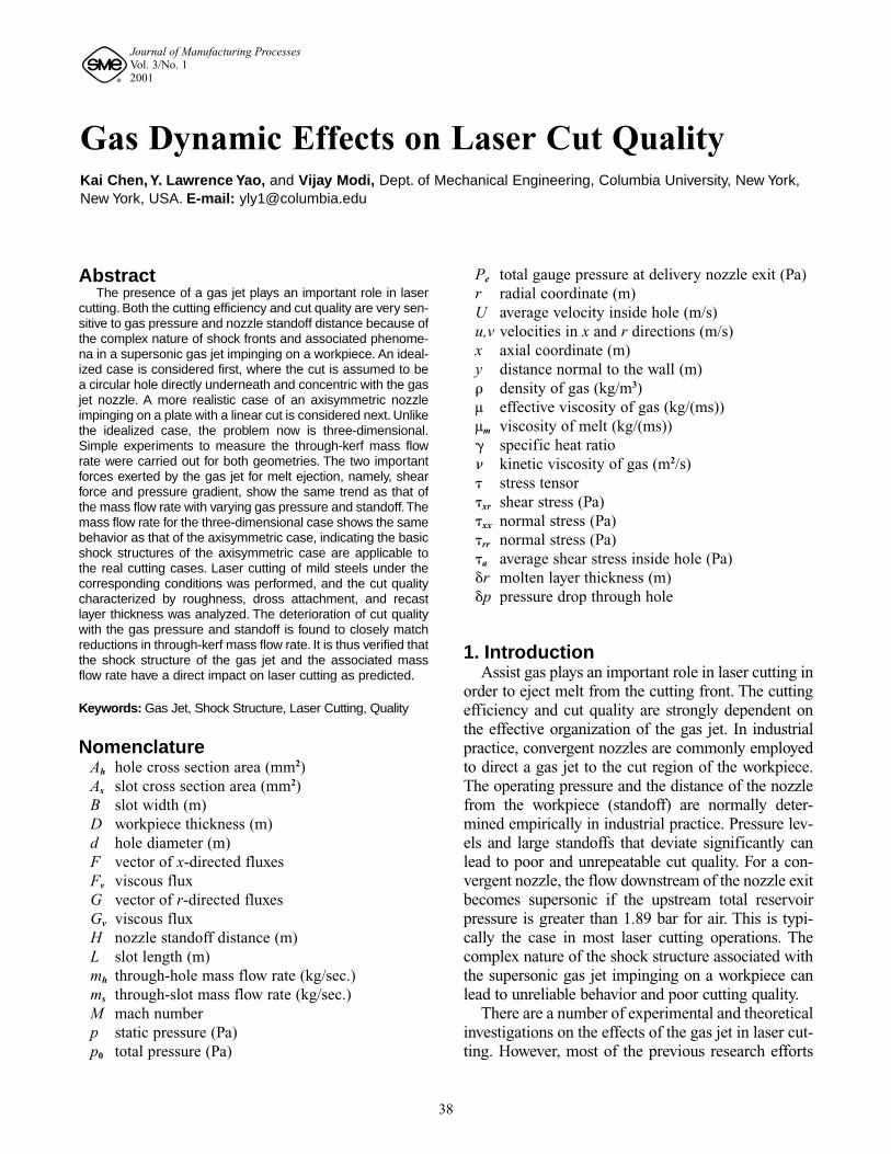
Figure 1Schematic of Computational Domain and Experimental Setup
for the Axisymmetric Case
Delivery nozzle
mh Impingement plate
(Workpiece) D (Thickness)
H (Standoff)
Collection box
Measurement nozzle
Velocimeter
d
x
Per
ComputationalDomain
(10)
where A is the cross section area of the hole. Fromthe scaling analysis, it is seen that both shear forceand pressure gradient are proportional to U, which isreflected in through-hole mass flow rate.
If the velocity profile of the molten material isassumed to be linear across the layer due to itsextreme thinness, the velocity of the molten materi-al can be calculated using the 1/7th power law ofmean velocity profile,11 that is
(11)
(12)
where V is the surface velocity of the molten layer, �is the kinetic viscosity of the gas, �r is the thicknessof the molten layer, and v* is the friction velocity.However, the molten layer thickness is also depen-dent on the gas velocity as well as cutting speed.12
Through-hole mass flow rate with variation ofstandoff distance and gas pressure was calculatedand measured in experiments. A simple experimentto measure the mass flow rate through the hole wasdesigned to validate the simulation results (Figure1). A collection box was placed directly underneaththe workpiece to collect the flow and direct it to ameasurement nozzle with a hole diameter much
larger than the hole in workpiece. The gas velocityleaving the measurement nozzle is thus considerablyreduced, permitting accurate measurement by a hot-film velocimeter.
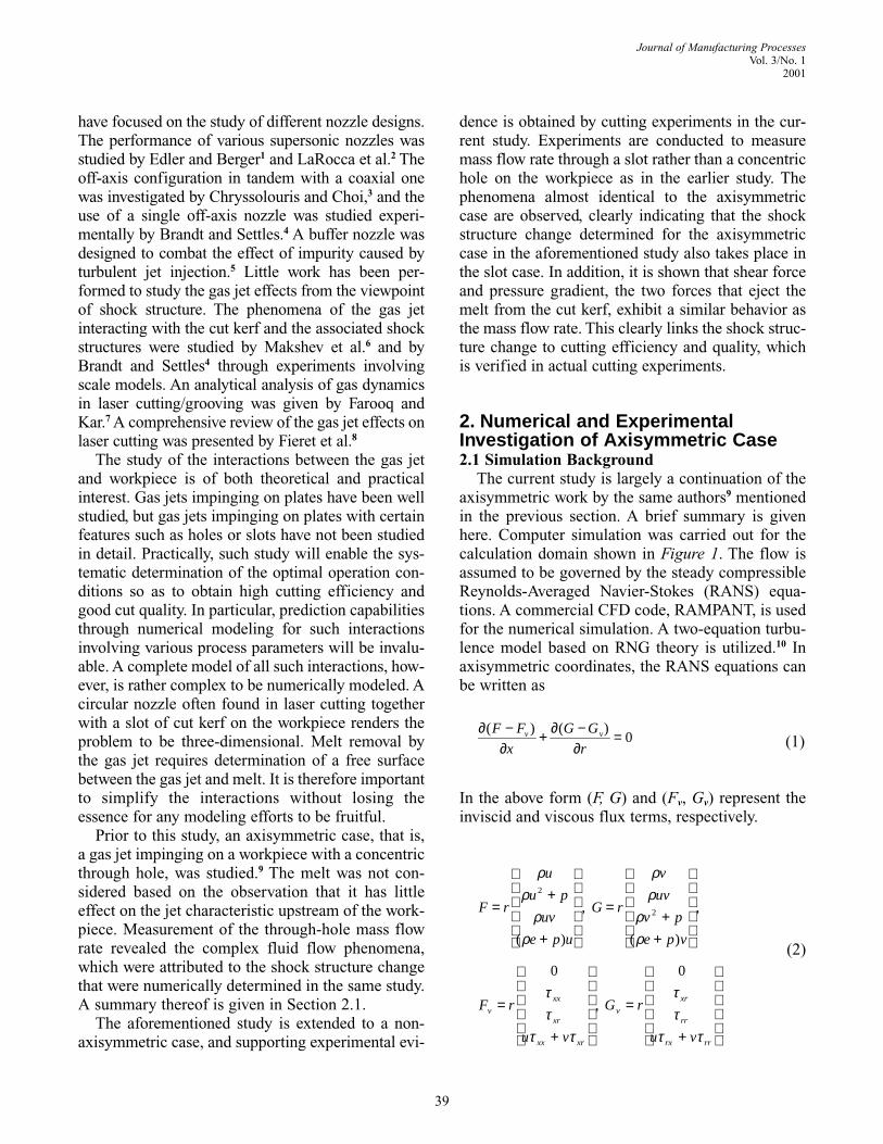
Figure 2 shows typical calculated shear force andpressure gradient effects inside the hole. It should benoted that at the top and bottom edge of the hole, theshear force and the pressure gradient display diver-gences, which are caused by numerical errors due toabrupt changes in geometry. In comparing theeffects of shear and pressure gradient, the shearlayer is taken to be the thickness of the molten layer�r and is assumed to be of the order of 10-5 m, whichis commonly reported.2,6 For convenience, it isassumed that �r = 2.0�10-5 m and D = 1.6 mm. Onethen observes that the contributions of the shearforce and the pressure gradient to the total force areof the same order. This is in agreement with theanalysis given by Vicanek et al.12
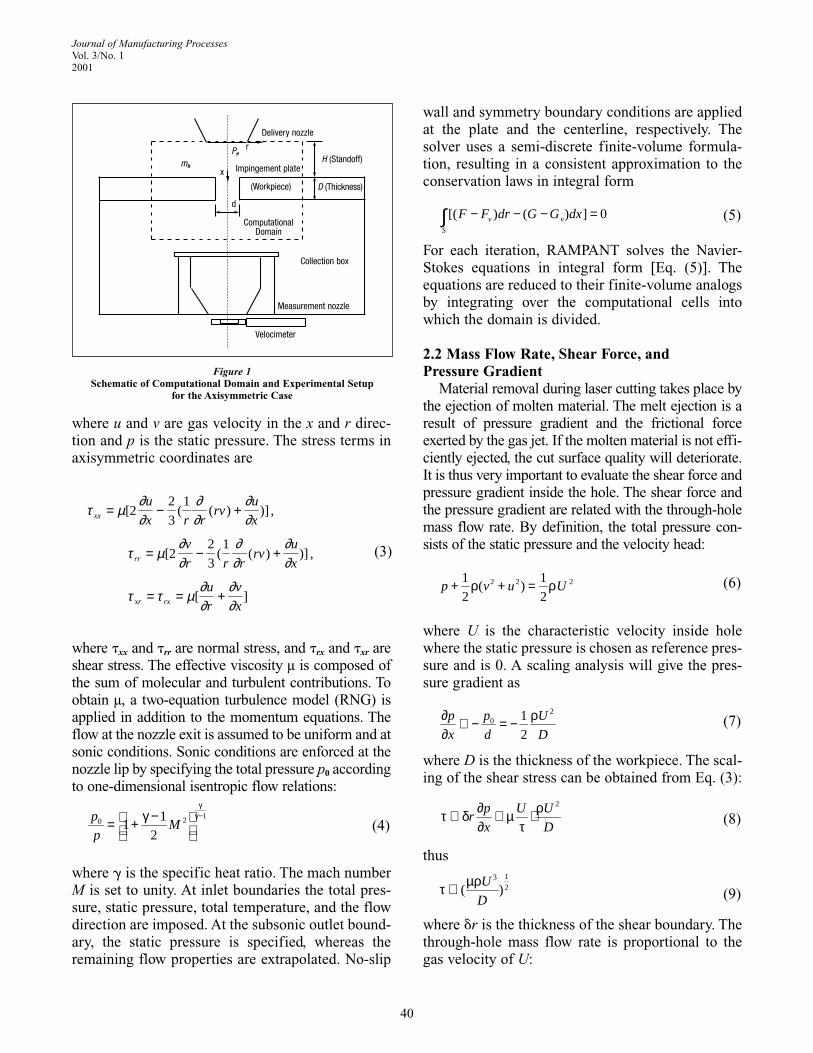
Figure 3 shows the effect of gas pressure on thevariation of average shear force inside the hole (�a)together with that of the through-hole mass flowrate. The shear force values close to either edges ofthe hole are assumed to be unreliable and hence notcounted in the averaging procedure. �a follows thesame pattern as mh when Pe varies. The maximum �a
corresponds to the maximum mh, and the minimum�a corresponds to the minimum mh, which confirmsthat the change of shear force due to the change ofshock structure can be reflected by the change ofthrough-hole mass flow rate. It was found that atlarge standoffs (H = 2 mm in this case), the through-
*2 mV
vr
µρ =δ
*
*
1/ 78.74( )2
U dv
v=
ν
hm AU∝ ρ
41
Journal of Manufacturing ProcessesVol. 3/No. 1
2001
Figure 2Shear Force and Pressure Gradient Effects Inside Hole
(Pe = 363 kPa, H = 1.5 mm, d = 0.508 mm)
0.0 0.2 0.4 0.6 0.8 1.0 1.2 1.4
Distance along hole (mm)
Shea
r and
pre
ssur
e gr
adie
nt (P
a)
�xr
1200
1100
1000
900
800
700
600
500
400
300
200
100
0
-(dp/dx)�r
Figure 3Variation of Through-Hole Mass Flow Rate and Average Shear Force
Inside Hole with Total Gas Pressure (H = 2 mm)
Average shear force inside hole (calculated data) Through-hole mass flow rate (measured data, fromChen et al.9)
100 150 200 250 300 350 400 450 500
Pe (kPa)
950
900
850
800
750
700
650
600
550
500
450
Shea
r (Pa
)
2.0
1.8
1.6
1.4
1.2
1.0
hole mass flow rate (mh) does not monotonouslyincrease with the gas pressure. Instead, it has a localmaximum and minimum at certain pressure levels.
Figure 4 shows the calculated melt surface veloc-ity versus gas pressure. The average surface veloci-ty of the melt flow is derived from Eqs. (11) and(12). Again, it is assumed that the thickness of themolten layer has a fixed value �r = 2.0�10-5 m forconvenience, although it may vary along the jetdirection and is dependent on gas velocity and cut-ting speed. The average gas velocity inside the holeis obtained from the through-hole mass flow rate mh.The other gas and melt properties are assumed to beconstant, though they may vary with temperature:
� = 1.2 kg/m3, � = 2.25�10-4 m2/s,µm = 5�10-3 kg/(ms), �r = 2.0�10-5 m
It is seen that the melt surface velocity shows the samepatterns as that of the shear force and through-holemass flow rate with the variation of the gas pressure.
The variation of shear force �a and through-holemass flow rate mh with standoff is shown in Figure 5.Again, �a and mh exhibit a similar pattern as H varieswhile gas pressure Pe is fixed. If the gas pressure isheld at a relatively high value (Pe = 363 kPa in thiscase), mh is found to decrease continuously withincreasing standoff until a critical value of the stand-off where a sudden jump in mh is observed. Similarly,the melt surface velocity with varying standoff canalso be calculated and shows the similar patterns andthe shear force and through-hole mass flow rate.
The above-described behaviors are essentiallyrepeated for different hole sizes; specifically, there isa “bump” in mh with increasing Pe while H is fixed at2 mm, and a “jump” in mh with increasing H while Pe
is fixed at 363 kPa. It was determined that they areassociated with changes in shock structure as gaspressure and standoff are varied, namely, the changeof shock structure either from direct interactionbetween the oblique shock and the normal shock toindirect interaction, or vice versa.. At lower Pe val-ues, the oblique shock waves meet at the centerlineand are reflected prior to interacting with the normalshock (Figure 6a). In this case, the total pressuredecrease downstream of the normal shock is small.At higher Pe values, the oblique shock interacts withthe normal shock directly, resulting in a much largertotal pressure reduction (Figure 6b). Thus, mh maynot always increase with Pe because of larger totalpressure reduction across the normal shock. On thecontrary, if Pe is fixed at a high level, the obliqueshock will interact with the normal shock directlyuntil H increases to a certain value where the obliqueshock starts to merge first. This corresponds to a sud-den jump in mh at a certain H value.
The axisymmetric study reveals that contributionsof shear force and pressure gradient are of the sameorder of magnitude and they follow the same profile asthat of through-hole mass flow rate with the varyinggas pressure and standoff. It is thus expected thatunder certain operating conditions when the mass flowrate is high, the shear force and pressure gradient arealso large, the melt is better ejected in laser cutting,
42
Journal of Manufacturing ProcessesVol. 3/No. 12001
Figure 4Variation of Average Melt Surface Velocity with Total Gas Pressure
(H = 2 mm)
100 150 200 250 300 350 400 450 500 550
Pe (kPa)
Mel
t vel
ocity
(m/s
)
12
10
8
6
4
2
0
Figure 5Variation of Through-Hole Mass Flow Rate and Average Shear Force
Inside Hole with Standoff Distance (Pe = 363 kPa)
Average shear force inside hole (calculated data)Through-hole mass flow rate (measured data,from Chen et al.9)
-0.5 0.0 0.5 1.0 1.5 2.0 2.5 3.0 3.5
H (mm)
1200
1100
1000
900
800
700
600
500
400
Shea
r (Pa
)
2.4
2.2
2.0
1.8
1.6
1.4
1.2
1.0
mh
(x10
4kg
/s)
mh
(x10
4kg
/s)
and the cut quality is relatively good. It will be shownin the subsequent sections that the generic behaviorsof the gas flow between the real cutting case and thatof this axisymmetric case are very similar.
3. Model Kerf ExperimentsIn laser cutting, the gas jet interacts with the work-
piece to generate a narrow cut kerf. The cut kerfgeometry renders the problem three-dimensional,leading to departure from axisymmetric behavior. Toexamine this departure, experiments were carried outby replacing the hole on the workpiece with a slotthat attempts to capture the essential geometric fea-ture of the real cut kerf. The mass flow rate throughthe slot was measured using the same collection boxand measurement nozzle as that used in measuringthe through-hole gas flow (Figure 1). The impinge-ment plate (workpiece) along with the collection boxare placed on a precision x-y table so that one end ofthe slot end can be adjusted to align with the deliverynozzle axis (Figure 7). The slot width (B) is set to be0.22 mm, which equals the average kerf width in thesubsequent real cutting experiments. Ideally, the slotlength needs to be relatively long compared with theslot width, as in the case of a real cutting kerf.However, the ability of a collection box to functionrequires that the pressure drop for the flow throughthe collection box is negligible compared to the pres-sure drop through the kerf. Thus, as the slot lengthincreases and the pressure drop through the kerfdecreases, a point is reached where the collection boxresistance may no longer be negligible, allowing gasflow entering the slot to begin to reemerge. It is
important to establish that the model kerf geometrydoes not reach such a point.
To establish this point, the variation in through-slot mass flow rate (ms) with varying slot length (L)was measured for three different gas pressure levels,as shown in Figure 8. As seen, ms first increases lin-early with L, then levels off and eventually decreasesas L exceeds about 1.8 mm. This decrease indicatesreemergence of the gas flow from the collection box,thus invalidating the measurement. Hence, the slotlength L was maintained at 1.1 mm to ensure accura-cy in measurement, while at the same time L is fivetimes larger than B, ensuring that the effect of the slotmimics a real cut kerf.
Figure 9 shows the effect of gas pressure on thethrough-slot (L = 1.1 mm) mass flow rate ms forstandoff distances H = 1.0, 1.5, and 2.0 mm. For H =1.0 mm, ms is found to monotonically and linearlyincrease with Pe. For H = 2.0 mm, however, ms firstincreases with total pressure until it reaches a local
43
Journal of Manufacturing ProcessesVol. 3/No. 1
2001
Figure 6aContour of Static Pressure (Pe = 138 kPa, d = 0.5 mm, H = 2 mm) inWhich Oblique Shock Merges Before Interacts with Normal Shock
1.33e+05
1.21e+05
1.09e+05
9.67e+04
8.45e+04
7.24e+04
6.02e+04
4.81e+04
3.59e+04
2.37e+04
1.16e+04
-5.92e+02
-1.28e+04
Figure 6bContour of Static Pressure (Pe = 276 kPa, d = 0.5 mm, H = 2 mm) in
Which Oblique Shock Interacts with Normal Shock Directly
1.76e+05
1.56e+05
1.36e+05
1.16e+05
9.66e+04
7.67e+04
5.69e+04
3.71e+04
1.73e+04
-2.55e+03
-2.24e+04
-4.22e+04
-6.20e+04
Figure 7Top View of Model Kerf Experiment Setup
Delivery nozzleSlot
Collection box
B
B
maximum at Pe = 325 kPa and then reduces even astotal gas pressure increases, until it reaches a localminimum and begins to increase again. For H = 1.5mm, ms behavior lies in between those of H = 1.0 mmand 2.0 mm, and the local maximum and minimumare not evident. These phenomena are similar to thoseof mh behavior in the axisymmetric case. The “bump”in ms with varying Pe for H = 2.0 mm is caused by thechange of shock structure as explained in Section 2.
Comparing the behavior of ms (H = 2.0mm and L= 1.1 mm) and the behavior of mh (H = 2.0 mm andd = 0.5 mm) of two cases with the same cross sec-tion area, it is seen that they resemble each otherexcept that the “bump” shifts to high Pe values(Figure 10). This is probably due to the fact that an
edge of the slot is positioned at the center of the noz-zle (Figure 7), causing less gas to enter the slot incomparison with the case of a concentric hole underthe same pressure. The precise ms behavior for a realcut kerf is likely to have a “bump” that shifts tolower Pe in comparison to the case of L = 1.1 mmbecause of more gas entering the slot.
The behavior of ms (L = 1.1 mm) with varyingstandoff is shown in Figure 11 for nozzle pressure Pe
= 125, 243, and 363 kPa. At Pe values of 125 and243 kPa, ms is relatively unaltered with increasing H.For Pe = 363 kPa, ms reduces continuously as Hincreases then suddenly jumps to a high value at acritical standoff. Again these phenomena are consis-tent with those of an axisymmetric case. The sudden
44
Journal of Manufacturing ProcessesVol. 3/No. 12001
Figure 8Variation of Measured Through-Slot Mass Flow Rate
with Slot Length L
H = 1 mm, Pe = 125 kPa H = 1 mm, Pe = 243 kPa H = 1 mm, Pe = 363 kPa
0.4 0.6 0.8 1.0 1.2 1.4 1.6 1.8 2.0 2.2 2.4
Slot length (mm)
ms
(x10
4kg
/s)
2.0
1.8
1.6
1.4
1.2
1.0
0.8
0.6
Figure 9Variation of Measured Through-Slot Mass Flow Rate Measurements
with Total Gas Pressure for L = 1.1 mm
H = 1.0 mmH = 1.5 mmH = 2.0 mm
100 150 200 250 300 350 400 450Pe (kPa)
ms
(x10
4kg
/s)
2.0
1.8
1.6
1.4
1.2
1.0
0.8
0.6
Figure 10Comparison of Through-Slot (L = 1.1 mm) and Through-Hole (d = 0.5
mm) Mass Flow Rate Measurements for H = 2.0 mm (As ˜ Ah)
ms, H = 2.0 mm, L = 1.1 mmmh, H = 2.0 mm, d = 0.5 mm
100 150 200 250 300 350 400 450Pe (kPa)
ms,
mh
(x10
4kg
/s)
2.0
1.8
1.6
1.4
1.2
1.0
0.8
Figure 11Variation of Through-Slot Mass Flow Rate Measurements with
Standoff Distance for L = 1.1 mm
Pe = 125 kPaPe = 243 kPaPe = 363 kPa
-0.5 0.0 0.5 1.0 1.5 2.0 2.5 3.0 3.5
H (mm)
ms
(x10
4kg
/s)
2.4
2.2
2.0
1.8
1.6
1.4
1.2
1.0
0.8
0.6
jump of ms for Pe = 363 kPa is due to the change inshock structure, as explained in Section 2.
Figure 12 shows the comparison of the through-slot mass flow rate for L = 1.1 mm with the through-hole mass flow rate for d = 0.5 mm, both for a Pe =363 kPa. Once again, the variations of ms and mh
with varying standoff are very similar. They bothshow a sudden “jump” at about H = 3.0 mm. Thefact that the mh value is larger than the ms value forthe same H value is due to more gas entering thehole than entering the slot, as explained earlier.
The overall trends in both through-slot andthrough-hole mass flow rate with varying gas pres-sure and standoff are the same. This implies that thegas jet interaction with a slot-type cut kerf has a sim-ilar shock structure to that of a concentric hole.Because the cut kerf width is considerably smaller ascompared with the exit diameter of the delivery noz-zle, the kerf geometry has little influence on theshock structure upstream of the workpiece. TheSchieren images of a geometry-scaled model kerfflow field provided by Brandt and Settles4 show verysimilar shock patterns to those of axisymmetriccases as shown in Figure 2. It has been seen that theshear force and the pressure gradient have similarprofiles as the mass flow rate with the variation ofthe gas pressure and standoff. It is reasonable toexpect that the variation of the cut quality with vary-ing gas pressure and standoff follows the same pat-tern of the variation of the through-slot mass flowrate. This is verified in the following section.
4. Laser Cutting Results andDiscussion
To verify the gas jet effects on laser cut quality, lasercutting experiments were carried out under the sameconditions as those of model kerf experiments. A PRC-1500 CO2 laser with maximum output 1.5 kW, operatedin CW and TEM00 modes was used for cutting experi-ments. The material being cut was cold-rolled mild steelof 1.6 mm thickness, which is the same thickness as theimpingement plate in the through-hole and model kerfexperiments for mass flow rate studies. In group-1experiments, air was used as assist gas for cutting, thegas pressure Pe was fixed at 363 kPa, and the nozzlestandoff distance H was varied. In group-2 experiments,oxygen was used for cutting, H was fixed at 2.0 mm,and Pe was varied from 122 kPa to 443 kPa, which is thetypical pressure range for oxygen-assisted cutting of
mild steels. Each group consisted of two experimentalruns under the same conditions. It should be noted thatthe pressure values read from a pressure meter were cal-ibrated to the total gauge pressure at the nozzle exit, thatis, Pe, by a relationship developed earlier.9 These oper-ating conditions given by gas pressure and standoff areidentical to the conditions under which the through-slotand through-kerf mass flow rates were measured. Toshow their effects on cut quality most distinctively, thelaser power and cutting speed were adjusted so thatsome samples were either barely cut through or not cutthrough at all. For group-1 experiments, the laser powerand cutting speed were 800 W and 35 mm/s, respec-tively. For group-2 experiments, the laser power was setto 200 W and the cutting speed was set as 40 mm/s.
In group-1 experiments with air-assisted cutting, theless oxidized iron in the air-assisted cutting has muchhigher viscosity and surface tension than the oxide-richmelt in oxygen-assisted cutting,13 and hence it is hard-er to eject the melt. Depending on the removal capabil-ity of the gas jet, resolidified melt (dross) may cling tothe bottom edge of the cut kerf. It is expected that moredross will be attached to the edge when the ejectingforce exerted by the gas jet is weak, and vice versa.Figure 13 shows the dross attachment on cut edge withfour different standoffs in the first run of the experi-ments. Dross was observed at H = 1.0 mm. The amountof dross increases for H = 1.5 mm. Cuts were incom-plete at H = 2.0 and 2.5 mm, which is equivalent toextremely severe dross attachment. The dross attach-ment then suddenly decreases to a minimum amount atH = 3.0 mm, and it increases slightly at H = 3.5 mm. Ifthe variation of dross attachment with standoff is com-
45
Journal of Manufacturing ProcessesVol. 3/No. 1
2001
Figure 12Comparison of Through-Slot (L = 1.1 mm) and Through-Hole (d = 0.5
mm) Mass Flow Rate Measurements for H = 2.0 mm (As ˜ Ah)
ms, Pe = 363 kPa, L = 1.1 mmmh, Pe = 363 kPa, d = 0.5 mm
-0.5 0.0 0.5 1.0 1.5 2.0 2.5 3.0 3.5
H (mm)
ms
(x10
4kg
/s)
2.4
2.2
2.0
1.8
1.6
1.4
1.2
1.0
0.8
0.6
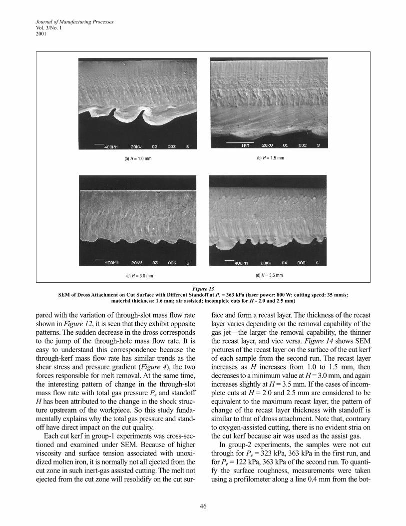
pared with the variation of through-slot mass flow rateshown in Figure 12, it is seen that they exhibit oppositepatterns. The sudden decrease in the dross correspondsto the jump of the through-hole mass flow rate. It iseasy to understand this correspondence because thethrough-kerf mass flow rate has similar trends as theshear stress and pressure gradient (Figure 4), the twoforces responsible for melt removal. At the same time,the interesting pattern of change in the through-slotmass flow rate with total gas pressure Pe and standoffH has been attributed to the change in the shock struc-ture upstream of the workpiece. So this study funda-mentally explains why the total gas pressure and stand-off have direct impact on the cut quality.
Each cut kerf in group-1 experiments was cross-sec-tioned and examined under SEM. Because of higherviscosity and surface tension associated with unoxi-dized molten iron, it is normally not all ejected from thecut zone in such inert-gas assisted cutting. The melt notejected from the cut zone will resolidify on the cut sur-
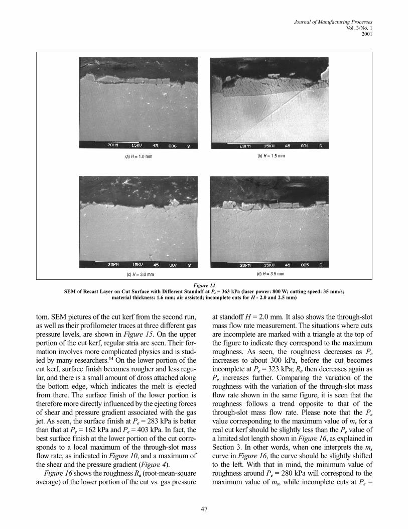
face and form a recast layer. The thickness of the recastlayer varies depending on the removal capability of thegas jet—the larger the removal capability, the thinnerthe recast layer, and vice versa. Figure 14 shows SEMpictures of the recast layer on the surface of the cut kerfof each sample from the second run. The recast layerincreases as H increases from 1.0 to 1.5 mm, thendecreases to a minimum value at H = 3.0 mm, and againincreases slightly at H = 3.5 mm. If the cases of incom-plete cuts at H = 2.0 and 2.5 mm are considered to beequivalent to the maximum recast layer, the pattern ofchange of the recast layer thickness with standoff issimilar to that of dross attachment. Note that, contraryto oxygen-assisted cutting, there is no evident stria onthe cut kerf because air was used as the assist gas.
In group-2 experiments, the samples were not cutthrough for Pe = 323 kPa, 363 kPa in the first run, andfor Pe = 122 kPa, 363 kPa of the second run. To quanti-fy the surface roughness, measurements were takenusing a profilometer along a line 0.4 mm from the bot-
46
Journal of Manufacturing ProcessesVol. 3/No. 12001
Figure 13SEM of Dross Attachment on Cut Surface with Different Standoff at Pe = 363 kPa (laser power: 800 W; cutting speed: 35 mm/s;
material thickness: 1.6 mm; air assisted; incomplete cuts for H - 2.0 and 2.5 mm)
(a) H = 1.0 mm (b) H = 1.5 mm
(c) H = 3.0 mm (d) H = 3.5 mm
tom. SEM pictures of the cut kerf from the second run,as well as their profilometer traces at three different gaspressure levels, are shown in Figure 15. On the upperportion of the cut kerf, regular stria are seen. Their for-mation involves more complicated physics and is stud-ied by many researchers.14 On the lower portion of thecut kerf, surface finish becomes rougher and less regu-lar, and there is a small amount of dross attached alongthe bottom edge, which indicates the melt is ejectedfrom there. The surface finish of the lower portion istherefore more directly influenced by the ejecting forcesof shear and pressure gradient associated with the gasjet. As seen, the surface finish at Pe = 283 kPa is betterthan that at Pe = 162 kPa and Pe = 403 kPa. In fact, thebest surface finish at the lower portion of the cut corre-sponds to a local maximum of the through-slot massflow rate, as indicated in Figure 10, and a maximum ofthe shear and the pressure gradient (Figure 4).
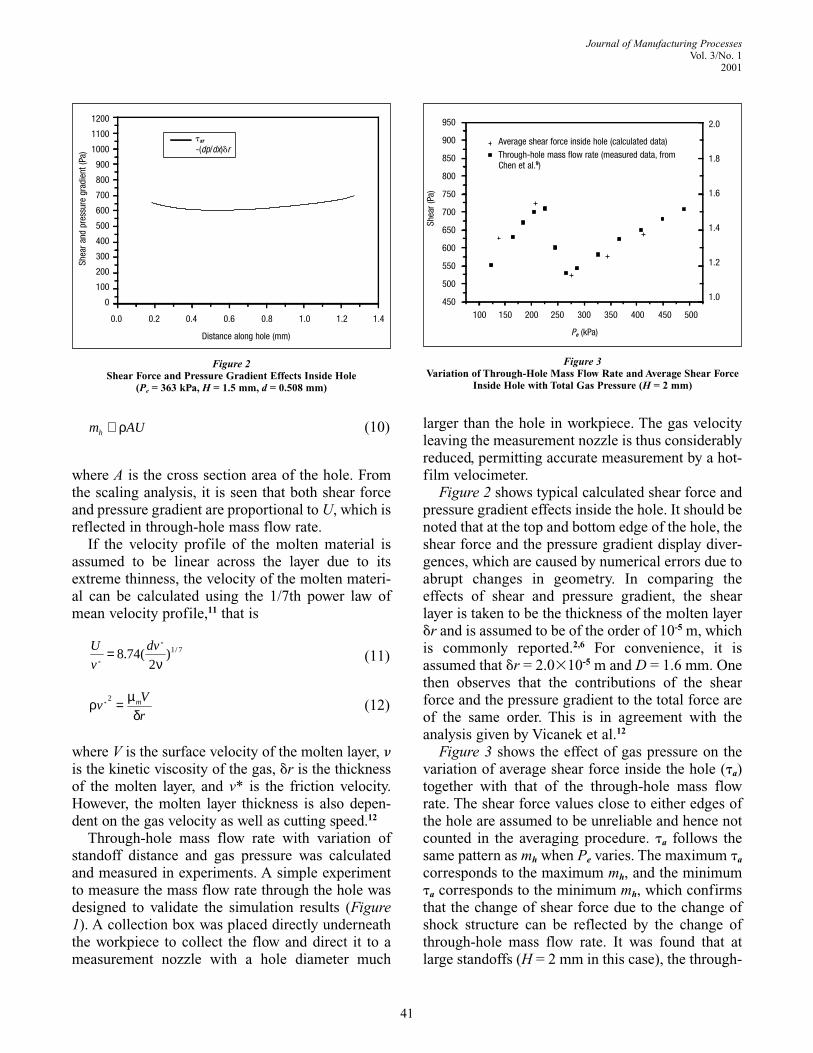
Figure 16 shows the roughness Ra (root-mean-squareaverage) of the lower portion of the cut vs. gas pressure
at standoff H = 2.0 mm. It also shows the through-slotmass flow rate measurement. The situations where cutsare incomplete are marked with a triangle at the top ofthe figure to indicate they correspond to the maximumroughness. As seen, the roughness decreases as Pe
increases to about 300 kPa, before the cut becomesincomplete at Pe = 323 kPa; Ra then decreases again asPe increases further. Comparing the variation of theroughness with the variation of the through-slot massflow rate shown in the same figure, it is seen that theroughness follows a trend opposite to that of thethrough-slot mass flow rate. Please note that the Pe
value corresponding to the maximum value of ms for areal cut kerf should be slightly less than the Pe value ofa limited slot length shown in Figure 16, as explained inSection 3. In other words, when one interprets the ms
curve in Figure 16, the curve should be slightly shiftedto the left. With that in mind, the minimum value ofroughness around Pe = 280 kPa will correspond to themaximum value of ms, while incomplete cuts at Pe =
47
Journal of Manufacturing ProcessesVol. 3/No. 1
2001
Figure 14SEM of Recast Layer on Cut Surface with Different Standoff at Pe = 363 kPa (laser power: 800 W; cutting speed: 35 mm/s;
material thickness: 1.6 mm; air assisted; incomplete cuts for H - 2.0 and 2.5 mm)
(a) H = 1.0 mm (b) H = 1.5 mm
(c) H = 3.0 mm (d) H = 3.5 mm

325 kPa correspond to the trough of the ms curve. It isthus seen that a higher through-kerf mass flow rate cor-responding to higher shear stress and pressure gradientresults in better surface finish, whereas a lower through-
kerf mass flow rate gives poor cut quality. The suddendrop of the mass flow rate with gas pressure for a stand-off of H = 2 mm is due to the aforementioned change ofthe shock structures upstream of the workpiece.
48
Journal of Manufacturing ProcessesVol. 3/No. 12001
Figure 15SEM and Profilometer Measurements of Cut Surface with Different Gas Pressure at 2.0 mm Standoff (laser power: 200 W; cutting speed: 40
mm/s; material thickness: 1.6 mm; oxygen assisted; incomplete cuts at Pe = 323 kPa, Pe = 363 kPa)
0.00 1.15 2.30 3.45 4.601000
-500
0
500
1000
Pe=162kPa
distance (mm)
0.00 1.15 2.30 3.45 4.60
1000
-500
0
500
1000
Pe=283kPa
distance (mm)
0.00 1.15 2.30 3.45 4.60
-1000
-500
0
500
1000
P =403kPa
distance (mm)
e
(a) Pe = 162 kPa
(b) Pe = 283 kPa
(c) Pe = 403 kPa
Distance (mm)
Distance (mm)
Distance (mm)
µmµm
µm

The experimental results show that the cut quality,including roughness, dross, and recast layer, vary withtotal gas pressure and standoff in a way strongly con-sistent with the pattern of change in the through-slotmass flow rate, which is in turn similar to the patternof change in the through-hole mass flow rate. The pat-tern of change in through-hole mass flow rate has beenattributed to the changes in shock structure as evi-denced in the axisymmetric simulation. Although theinteractions between laser and melt are not taken intoaccount when the shock structures are predicted in thenumerical simulation under the assumption that suchinteractions have insignificant effects on the shockstructures upstream of the workpiece, this study showsthat the primary behavior of shock structure in lasercutting is very similar to that in the axisymmetriccase and that it directly influences the cut quality.
5. ConclusionsThe effects of a gas jet in laser cutting are exam-
ined. It is found that the removal capability of thegas jet, in terms of shear stress and pressure gradi-ent, is affected by the shock structure of the imping-ing jet interacting with the workpiece. The through-hole or through-slot mass flow rate is found to be akey indicator of shock structure and removal capa-bility of the gas jet. When an oblique shock directlyinteracts with the normal shock, a large reduction in
mass flow rate is observed. However, when anoblique shock merges upstream of its interactionwith the normal shock, the reduction of the massflow rate is small, preserving the removal capability.The variation of measured through-slot mass flowrate with gas pressure and standoff distance is simi-lar to that of the through-hole mass flow (axisym-metric case), indicating that the basic shock struc-ture of the two cases remains unchanged.Experimental measurement of cut quality character-istics such as roughness, dross attachment, andrecast layer thickness confirms their associationwith the shock structure and gas jet removal capa-bility as predicted.
AcknowledgmentThe support for this work received from NSF under
grant DMI-9500181 is gratefully acknowledged.
References1. R. Edler and P. Berger, “New Nozzle Concept for Cutting with High
Power Lasers,” Proc. of ICALEO’91, Orlando, FL, 1991, Laser Institute ofAmerica, pp253-262.
2. A.V. LaRocca et al., “Nozzle Design to Control Fluid-DynamicEffects in Laser Cutting,” SPIE (v2207, 1994), pp169-180.
3. G. Chryssolouris and W.C. Choi, “Gas Jet Effects on Laser Cutting,”SPIE CO2 Lasers and Applications (v1042, 1989), pp86-96.
4. A.D. Brandt and G.S. Settles, “Effect of Nozzle Orientation on theGas Dynamics of Inert-Gas Laser Cutting of Mild Steel,” Journal of LaserApplication (v9, 1997), pp269-277.
5. W. O’Neill and J.T. Gabzdyl, “The Mass Transfer Behaviour of GasJets in Laser Cutting,” Welding in the World (v15, n1, 1995), pp6-11.
6. N.K. Makashev et al., “Gas Hydrodynamics of CW Laser Cutting ofMetals in Inert Gas,” SPIE (v2257, 1994), pp2-9.
7. K. Farooq and A. Kar, “Removal of Laser-Melted Material with anAssist Gas,” Journal of Applied Physics (v83, n12, June 1998).
8. J. Fieret et al., “Overview of Flow Dynamics in Gas-Assisted LaserCutting,” SPIE High Power Lasers (v801, 1987), pp243-250.
9. K. Chen, Y.L. Yao, and V. Modi, “Numerical Simulation of the Gas JetEffects in Laser Machining,” Proc. of ICALEO’98, Section B, Orlando, FL,1998, Laser Institute of America, pp120-129.10. V. Yakhot and S.A. Orszag, “Renormalization Group Analysis ofTurbulence - I. Basic Theory,” Journal of Scientific Computing (v1, n1,1986), pp3-51.11. H. Schlichting, Boundary-Layer Theory (New York: McGraw-HillBook Co., 1979).12. M. Vicanek et al., “Hydrodynamic Instability of Melt Flow in LaserCutting,” Journal of Physics D: Applied. Physics (v20, 1986), pp140-145.13. A. Ivarson et al., “The Oxidation Dynamics of Laser Cutting of MildSteel and the Generation of Striations on the Cut Edge,” Journal ofMaterials Processing Technology (v40, 1994), pp359-374.14. K. Chen and Y.L. Yao, “Striation Formation and Melt Removal in theLaser Cutting Process,” Journal of Mfg. Processes (v1, n1, 1999), pp43-53.
Authors’ BiographiesDr. Kai Chen was a PhD candidate and is currently with Unplugin, Inc.,
a software company in New York City. Dr. Y. Lawrence Yao is an associateprofessor with research interests in manufacturing and design, lasermachining, laser forming, and laser shock processing. Dr. Vijay Modi is aprofessor with research interests in thermo-fluid science, CFD, microflu-idics, MEMS, sensors, and optimal design.
49
Journal of Manufacturing ProcessesVol. 3/No. 1
2001
Figure 16Roughness (Ra) Measurement at Low Portion of Cut Surface andThrough-Slot Mass Flow Rate Measurement with Different Gas
Pressure at H = 2.0 mm (laser power: 200 W; cutting speed: 40 mm/s;material thickness: 1.6 mm; oxygen assisted)
Ra (1st run) Ra (2nd run) Incomplete cut (1st run)Incomplete cut (2nd run)
ms, L = 1.1 mm
100 150 200 250 300 350 400 450
Pe (kPa)
R a(µ
m)
6.5
6.0
5.5
5.0
4.5
4.0
3.5
3.0
2.5
ms
(x10
4kg
/s)
1.8
1.6
1.4
1.2
1.0