Garlock Butterfly Valves Technical Catalog · Leaders in Sealing Integrity Garlock Butterfly Valves...
32
Leaders in Sealing Integrity Garlock Butterfly Valves Technical Catalog Trusted throughout the chemical, petrochemical & many other industries
Transcript of Garlock Butterfly Valves Technical Catalog · Leaders in Sealing Integrity Garlock Butterfly Valves...

Leaders in Sealing Integrity
Garlock Butterfly ValvesTechnical CatalogTrusted throughout the chemical, petrochemical & many other industries
Table of ConTenTs
GarloCk buTTerfly ValVes
Overview .......................................................................................................................................................................................................................3
The correct type of lining ..............................................................................................................................................................................................4
Head flange, body, flange type, design and shaft sealing ............................................................................................................................................5
Materials........................................................................................................................................................................................................................6
Production .....................................................................................................................................................................................................................7
Test engineering ............................................................................................................................................................................................................8
Standards ......................................................................................................................................................................................................................9
The correct material choice for your application .........................................................................................................................................................10
Gar-seal, safeTy-seal and mobile-seal
Applications GAR-SEAL .............................................................................................................................................................................................. 11
Applications SAFETY-SEAL ........................................................................................................................................................................................ 12
Applications MOBILE-SEAL ....................................................................................................................................................................................... 13
Materials...................................................................................................................................................................................................................... 14
Dimensions, Wafer ..................................................................................................................................................................................................... 15
Dimensions, Lug .........................................................................................................................................................................................................16
Exploded view ............................................................................................................................................................................................................. 17
sTerile-seal
Applications ................................................................................................................................................................................................................. 18
Bacteria won’t survive ................................................................................................................................................................................................ 19
2-chamber-system guarantees product safety ...........................................................................................................................................................20
Materials......................................................................................................................................................................................................................21
Dimensions, Wafer .....................................................................................................................................................................................................22
Dimersions, Lug ..........................................................................................................................................................................................................23
Exploded view .............................................................................................................................................................................................................24
anCillary ComponenTs
Mounting flange ..........................................................................................................................................................................................................25
Hand-Lever ..................................................................................................................................................................................................................26
Gear Operator .............................................................................................................................................................................................................27
TeChniCal deTails
Technical data ..............................................................................................................................................................................................................28
Special vacuum design ...............................................................................................................................................................................................30

Leaders in Sealing Integrity
Gar-seal
Garlock Butterfly Valves
GAR-SEALGAR-SEAL valves are used extensively where corrosive, abra-sive and toxic media need to be reliably controlled. They are typically used for accurate control, throttling and shut-off duties in the chemical, petrochemical, chlorine, paper, electro-plating and many other industries. GAR-SEAL butterfly valves offer reduced maintenance requirements and increased operational reliability.
MOBILE-SEALMOBILE-SEAL valves are used on road tanker vehicles, railway wagons, silos and other transportation and storage containers where high chemical resistance, reliability and special safety requirements are essential. MOBILE-SEAL is EN 14432 approved.
3
Trusted throughout chemical, petrochemical and many other industries
for CorrosiVe and abrasiVe media
Garlock Butterfly Valves
Butterfly ValvesGarlock Butterfly Valves are renowned throughout the chemical, petrochemical, process and many other industrial sectors for their quality, performance and reliability in arduous conditions. Garlock valves set the standard in TA-Luft compliance, plus the valves are certified with S1L 3 according to EN 61508.
mobile-sealsafeTy-seal
SAFTEY-SEALSAFETY-SEAL valves are used in applications where corrosive, abrasive and toxic media need to be handled and electrostatic charges must be avoided at the same time.
STERILE-SEALSTERILE-SEAL valves are used in applications where sterile processes need to be maintained in the pharmaceutical and food industries without unnecessary and costly overhauls and replacement. The special characteristic of this valve is its external sterilization capability. The design is such that the critical „dead“ areas of the valve, as well as the disc, body liner and seals, can be sterilized with steam without coming in contact with the process medium.
sTerile-seal
Leaders in Sealing Integrity
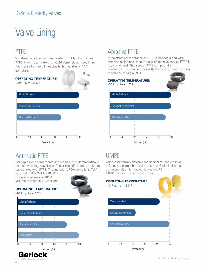
Antistatic PTFEFor explosive environments and medias, this electrostatically conductive lining is available. The service life is comparable to valves lined with PTFE. The material is FDA compliant. TÜV approval. (TÜV 941 F 416 601). Surface resistance ≤ 106 Ω. Volume resistance ≤ 106 Ω cm.
operaTinG TemperaTure:-40°F up to +392°F
0 20 40 60 80 100
Media Resistant
Temperature Resistant
Abrasion Resistant
Conductance
Percent (%)
4
Garlock Butterfly Valves
PTFEVoid-free body liner and disc isostatic molded from virgin PTFE. High material density >2.16g/cm3. Guaranteed lining thickness of at least 3mm plus high crystallinity. FDA compliant.
operaTinG TemperaTure:-40°F up to +392°F
0 20 40 60 80 100
Media Resistant
Temperature Resistant
Abrasion Resistant
ConductancePercent (%)
Valve Lining
Abrasive PTFEIf the chemical resistance of PTFE is needed along with abrasion resistance, then the use of abrasive service PTFE is recommended. This special PTFE compound is resistant to mechanical wear with almost the same chemical resistance as virgin PTFE. operaTinG TemperaTure:-40°F up to +392°F
0 20 40 60 80 100
Media Resistant
Temperature Resistant
Abrasion Resistant
ConductancePercent (%)
UMPEUsed in extremely abrasive media applications while still offering excellent chemical resistance. Garlock offers a complete, ultra high molecular weight PE (UMPE) liner and encapsulated disc.
operaTinG TemperaTure:-40°F up to +185°F
0 20 40 60 80 100
Media Resistant
Temperature Resistant
Abrasion Resistant
ConductancePercent (%)
Leaders in Sealing Integrity
Valve Reliability
5
Garlock Butterfly Valves
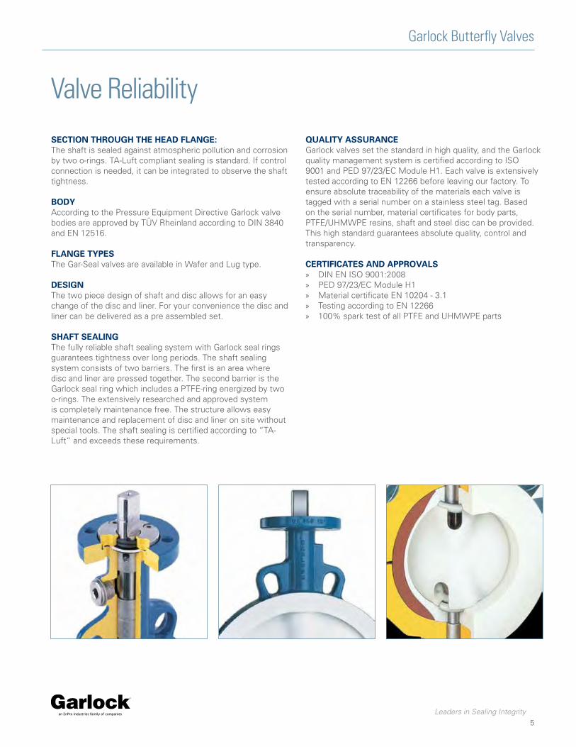
seCTion ThrouGh The head flanGe:The shaft is sealed against atmospheric pollution and corrosion by two o-rings. TA-Luft compliant sealing is standard. If control connection is needed, it can be integrated to observe the shaft tightness. body According to the Pressure Equipment Directive Garlock valve bodies are approved by TÜV Rheinland according to DIN 3840 and EN 12516. flanGe Types The Gar-Seal valves are available in Wafer and Lug type. desiGn The two piece design of shaft and disc allows for an easy change of the disc and liner. For your convenience the disc and liner can be delivered as a pre assembled set. shafT sealinG The fully reliable shaft sealing system with Garlock seal rings guarantees tightness over long periods. The shaft sealing system consists of two barriers. The first is an area where disc and liner are pressed together. The second barrier is the Garlock seal ring which includes a PTFE-ring energized by two o-rings. The extensively researched and approved system is completely maintenance free. The structure allows easy maintenance and replacement of disc and liner on site without special tools. The shaft sealing is certified according to “TA-Luft“ and exceeds these requirements.
QualiTy assuranCeGarlock valves set the standard in high quality, and the Garlock quality management system is certified according to ISO 9001 and PED 97/23/EC Module H1. Each valve is extensively tested according to EN 12266 before leaving our factory. To ensure absolute traceability of the materials each valve is tagged with a serial number on a stainless steel tag. Based on the serial number, material certificates for body parts, PTFE/UHMWPE resins, shaft and steel disc can be provided. This high standard guarantees absolute quality, control and transparency.
CerTifiCaTes and approVals » DIN EN ISO 9001:2008 » PED 97/23/EC Module H1 » Material certificate EN 10204 - 3.1 » Testing according to EN 12266 » 100% spark test of all PTFE and UHMWPE parts
Leaders in Sealing Integrity
Materials
6
Garlock Butterfly Valves
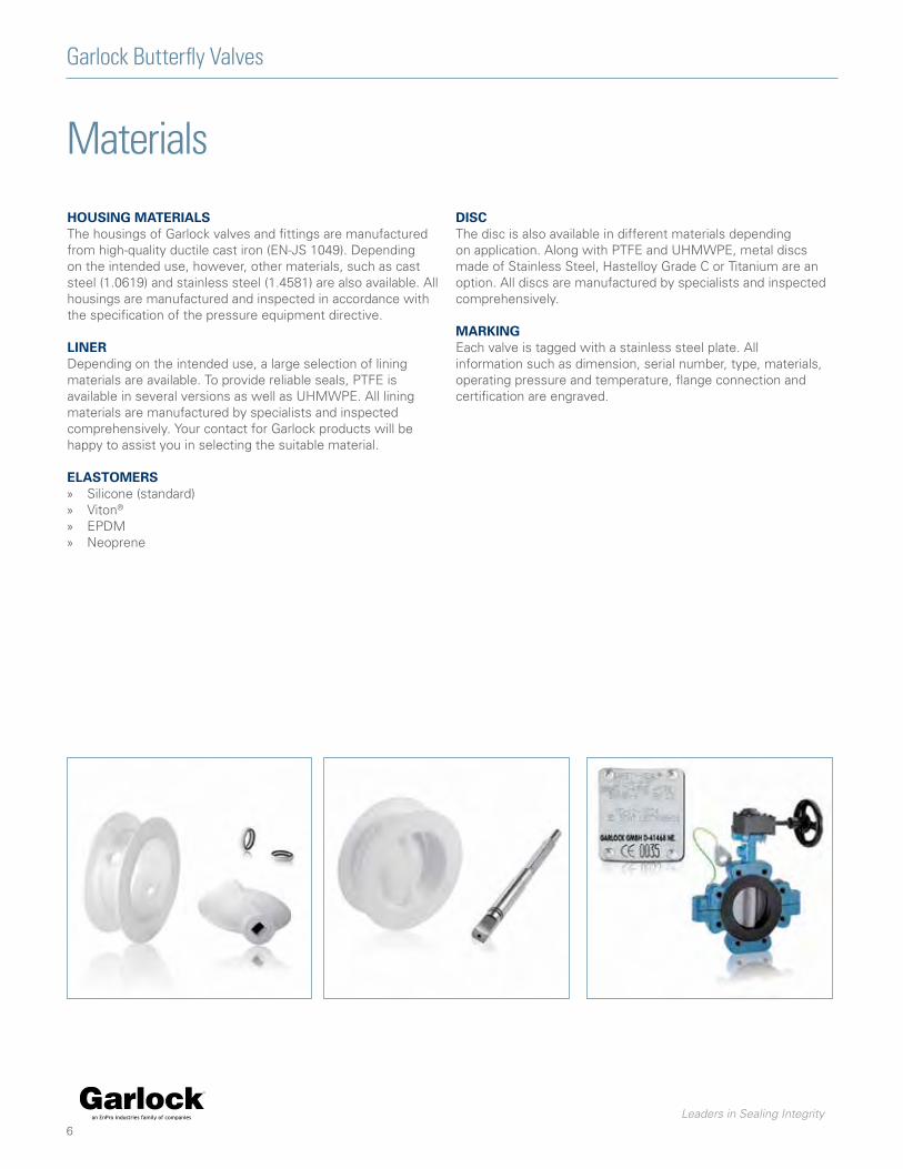
housinG maTerialsThe housings of Garlock valves and fittings are manufactured from high-quality ductile cast iron (EN-JS 1049). Depending on the intended use, however, other materials, such as cast steel (1.0619) and stainless steel (1.4581) are also available. All housings are manufactured and inspected in accordance with the specification of the pressure equipment directive.
linerDepending on the intended use, a large selection of lining materials are available. To provide reliable seals, PTFE is available in several versions as well as UHMWPE. All lining materials are manufactured by specialists and inspected comprehensively. Your contact for Garlock products will be happy to assist you in selecting the suitable material.
elasTomers » Silicone (standard) » Viton®
» EPDM » Neoprene
disCThe disc is also available in different materials depending on application. Along with PTFE and UHMWPE, metal discs made of Stainless Steel, Hastelloy Grade C or Titanium are an option. All discs are manufactured by specialists and inspected comprehensively.
markinGEach valve is tagged with a stainless steel plate. All information such as dimension, serial number, type, materials, operating pressure and temperature, flange connection and certification are engraved.

Leaders in Sealing Integrity
7
Garlock Butterfly Valves
Production
All processes have been defined through our ISO 9001 quality assurance system. The system is regularly reviewed and is being constantly improved. Quality, service and flexibility of the highest order are standard requirements we impose on ourselves and all our suppliers. With our production facility in Germany and stock all over the world, we are in a position to react to your global requirements in a very short time.
We manufacture each valve according to customer requirements. In doing so, we carry out all necessary configurations as per your specifications.
approVals » PED 97/23/EC » TA Luft / VDI 2440 » EN 61508 - SIL 3 » TR-Certificate » Chlorine Approval (RUS) » EN 14432 (Mobile Seal) » EN 15848-1
CusTom-Tailored serViCe:We are happy to help you to find the most suitable product for your particular application. In this respect, we have a high number of standard products available to you. In addition, project planning and design of custom-made solutions for our customers is one of our strengths, where we draw on decades of experience as a global manufacturer of seals and valves.
We offer professional consulting and project planning that is geared for your requirements. You’ll benefit from our individual on-site support services which are specifically tailored to meet your company’s needs. We conduct training seminars, help optimize inventory, reduce emissions, ensure functionality and prevent costly downtime. Our experienced employees will be happy to assist you at any time.

Leaders in Sealing Integrity
8
Garlock Butterfly Valves
Test EngineeringTesTinG All our valves are tested according to EN 12266-1 before they are sent out to you. Standard tests are body strength (P10), body tightness (P11) and seat tightness (P12). A functional test is also performed.
dimensions of liner ThiCkness On all PTFE parts, the liner thickness is checked in accordance with specific measuring methods. The test ensures that the required thicknesses are consistent for all parts. This measurement is indicative of the special attention paid to quality requirements of GAR-SEAL valves. This guarantees a long and reliable lifetime of PTFE and UHMWPE parts during operation.
To ensure conistent high quality valves all components are subjected to stringent testing running in parallel with all stages of production.
VaCuum GAR-SEAL valves are suitable for use in a vacuum service. For use in practical applications at elevated temperatures and simultaneously high vacuums there are special vacuum linings with increased wall thickness available.
ConduCTiViTy The PTFE body lining and the lining of the disc of the SAFETY-Seal (conductive version) are all checked for the required conductivity. These measurements are carried out with the resistivity measurement device in accordance with the specific guidelines. This ensures that electrostatic loads are safely discharged during operations.

Leaders in Sealing Integrity
9
Garlock Butterfly Valves
Standards
faCe-To-faCe dimensions » ISO 5752 Table 5 short » ASME B16.10
(2“ to 12“ Table Narrow 14“ to 24“ Table Wide) » DIN EN 558-1 GR 20 » MSS-SP 67
(2“ to 12“ Table Narrow 14“ to 24“ Table Wide) » API 609
(2“ to 12“ Category A 14“ to 24“ Category B)
adapTer flanGe » DIN/ ISO 5211 » NF E 29-402
body Types » Wafer » Lug » With long neck for insulation in accordance with HeizAnl.V
(German Heating Installations Ordinance)
body sTrenGTh » DIN EN 12516 T2 (DIN 3840), tested within the scope
certification according to PED 97/23/EC Module H1 body maTerials » Spheroidal graphite cast iron
(EN-JS1049, 0.7043) » Cast steel (GS-C 25, 1.0619) » Stainless steel casting
(G-X5CrNiMoNb 18 10, 1.4581)
shafT maTerials » 1.4313 up through 12“ » 1.4021 above 12“
flanGe ConneCTion » ASME B16.5 Class 150 lbs
(Design RF, FF) » EN 1092 PN 10/16 (Design A/B)
– (Available upon request)
TesTinG » EN 12266 P10 » EN 12266 P11 » EN 12266 P12 Leak rate A
pTfe lininG » void-free » isostatic pressed » high density (min. 2.16 g/cm³) » lining thickness min. 3 mm » vacuum lining up to 10 mm available
VaCuum TiGhTness » q Hemax< 10-6 mbar 1·s-1
idenTifiCaTion » DIN EN 19 » AD 2000 data sheet A4
ValVe disC aliGnmenT » Centrally, i.e. energy-saving
CharaCTerisTiC » Linear

Leaders in Sealing Integrity
Material Selection
10
Garlock Butterfly Valves
Valve material design Type
1Valve Body
2Body Liner
3Disc
4Specific Design
Body Liner
5Valve Type
6Body Type
Code Material Code Material Code Material Code Material Code Material Code Material
1 Ductile Cast IronEN-JS 1049(0.7043)
1 PTFE** 1 PTFE** A Antistatic(SAFETY-SEAL)
V Vacuum W WAFERRing Body
2 Cast SteelGS-C 25(1.0619)
2 UHMWPE*** 2 UHMWPE*** C abrasive service SV Special vacuum
L LUGFlange-on-Body
3 Stainless Steel(1.4581)
3 Stainless Steel(1.4581)
S STERILE-SEAL MOBILE-SEAL
4 Hastelloy C*(2.4602)
Code With existing pipe flanges
5 Titanium* (3.7035)
W-T MOBILE-SEAL Wafer
L-T MOBILE-SEAL Lug
W-WT MOBILE-SEAL
Drilling according to DIN 28459
examples 1 2 3 4 5 6
GAR-SEAL, WAFER Design 1 1 1 - - W MT
SAFETY-SEAL, LUG Design 3 1 1 A - L MT
MOBILE-SEAL, WAFER Design, acc. to TW standard 1 1 1 - - W-WT MT
STERILE-SEAL, LUG Design, antistatic 3 1 3 S - L
SAFETY-SEAL, WAFER Design, antistatic 2 1 1 A - W MT
GAR-SEAL, WAFER Design vacuum lining 1 1 1 - V W MT
Performance Data2“ - 24“
Nominal Pressuremax. 232 psi (<12”)up to full vacuum(depending upon temperature)
Operating temperature-40°F to +392200°F (for PTFE**)-40°F to +185°F (for UHMWPE***)
MT = GAR-SEAL Butterfly Valvescomply with the TA-Luft regulations.
* upon request** Polytetrafluorethylene*** Ultrahighmoleculare Polyethylene
All information and recommendations contained in this catalogue are based on many years of experience and the current state of technology. Unknown factors may, however, limit generally accepted knowledge. Binding statements regarding the compatibility of our products are therefore possible only after practical onsite tests under operating conditions. Information contained in our catalog does therefore not constitute or imply any representation of warrantee. While the utmost care has been used in compiling this catalogue, we assume no responsibility for errors. Specifications subject to change without notice. This edition cancels all previous issues. Subject to change without notice.

Leaders in Sealing Integrity
ApplicationsGar-seal
11
Garlock Butterfly Valves
GAR-SEAL butterfly valves are used where corrosive, abrasive and toxic media need to be controlled. GAR-SEAL valves are used for controlling, throttling and shutting off purposes in the chemical, petrochemical and chlorine industry as well as in electroplating, the paper industry and many other industries.
dimensions » 2“ up to 24“
flanGe ConneCTion
» ASME B16.5 class 150 lbs (design RF/FF) » EN 1092 PN 10/16 (Design A/B)
– (Available upon request)
faCe-To-faCe dimensions » ISO 5752 Table 5 short » ASME B16.10
(2“ to 12“ Table Narrow 14“ to 24“ Table Wide) » DIN EN 558-1 GR 20 » MSS-SP 67
(2“ to 12“ Table Narrow 14“ to 24“ Table Wide) » API 609
(2“ to 12“ Category A 14“ to 24“ Category B)
body sTrenGTh » DIN/ EN 12516 T2 (DIN 3840) » tested within the scope of the inspection body designate
by Module H1
operaTinG pressure » 2“ - 12“ 232 psi » above 12“ 145 psi (depending on operating temperature)
TesTinG » EN 12266 P10 » EN 12266 P11 » EN 12266 P12 Leak rate A
bodies » Wafer and Lug design with long neck for insulation
VaCuum » up to 1 mbar abs. (depending on size and temperature)
TemperaTure ranGe » -40 °F up to +392 °F (depending on material)
head flanGe » EN ISO 5211 » NF E 29-402
liner » PTFE » Abrasive PTFE » UHMWPE

Leaders in Sealing Integrity
12
Garlock Butterfly Valves
ApplicationssafeTy-seal
SAFETY-SEAL valves are used in applications where corrosive, abrasive and toxic media need to be insulated against electrostatic charges. SAFETY-SEAL valves offer long life and reduced maintenance efforts and extra safety.
dimensions » 2“ up to 24“
flanGe ConneCTion
» ASME B16.5 class 150 lbs (design RF/FF) » EN 1092 PN 10/16 (Design A/B)
– (Available upon request)
faCe-To-faCe dimensions » ISO 5752 Table 5 short » ASME B16.10
(2“ to 12“ Table Narrow 14“ to 24“ Table Wide) » DIN EN 558-1 GR 20 » MSS-SP 67
(2“ to 12“ Table Narrow 14“ to 24“ Table Wide) » API 609
(2“ to 12“ Category A 14“ to 24“ Category B)
body sTrenGTh » DIN/ EN 12516 T2 (DIN 3840) » tested within the scope of the inspection body designate
by Module H1
operaTinG pressure » 2“ - 12“ 232 psi » above 12“ 145 psi (depending on operating temperature)
TesTinG » EN 12266 P10 » EN 12266 P11 » EN 12266 P12 Leak rate A
bodies » Wafer and Lug design with long neck for insulation
VaCuum » up to 1 mbar abs. (depending on size and temperature)
TemperaTure ranGe » -40 °F up to +392 °F (depending on material)
head flanGe » EN ISO 5211 » NF E 29-402
liner » Antistatic PTFE

Leaders in Sealing Integrity
13
Garlock Butterfly Valves
Applicationsmobile-seal
MOBILE-SEAL valves are used on road tanker vehicles, railway wa-gons,silos and other transportation and storage containers where high chemical resistance, reliability and special safety requirements are essential.
dimensions » 2“ up to 24“
flanGe ConneCTion
» ASME B16.5 class 150 lbs (design RF/FF) » EN 1092 PN 10/16 (Design A/B) » DIN 28459 PN10
– (Available upon request)
faCe-To-faCe dimensions » ISO 5752 Table 5 short » ASME B16.10
(2“ to 4“ Table Narrow) » DIN EN 558-1 GR 20 » MSS-SP 67
(2“ to 4“ Table Narrow) » API 609
(2“ to 14“ Category A)
body sTrenGTh » DIN/ EN 12516 T2 (DIN 3840) » tested within the scope of the inspection body designate
by Module H1
operaTinG pressure » 2“ - 4“ 145 psi (depending on operating temperature)
TesTinG » EN 12266 P10 » EN 12266 P11 » EN 12266 P12 Leak rate A
bodies » Wafer and Lug design with long neck for insulation
VaCuum » up to 1 mbar abs. (depending on size and temperature)
TemperaTure ranGe » -40 °F up to +392 °F (depending on material)
head flanGe » EN ISO 5211 » NF E 29-402
liner » PTFE
Leaders in Sealing Integrity
14
Garlock Butterfly Valves
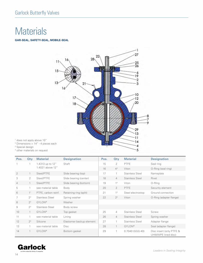
MaterialsGar-seal, safeTy-seal, mobile-seal
pos. Qty material designation pos. Qty material designation
1 1 1.4313 up to 12”1.4021 above 12”
Shaft 15 2 PTFE Seal ring
16 44 Viton O-Ring (seal ring)
2 1 Steel/PTFE Slide bearing (top) 17 1 Stainless Steel Nameplate
3 2 Steel/PTFE Slide bearing (center) 18 4 Stainless Steel Rivet
4 1 Steel/PTFE Slide bearing (bottom) 19 14 Viton O-RIng
5 1 see material table Body 20 2 PTFE Security element
6 11 PTFE, carbon reinf. Retaining ring (split) 21 13 Steel electrostop Ground connection
7 22 Stainless Steel Spring washer 22 24 Viton O-Ring (adapter flange)
8 22 GYLON® Washer
9 22 Stainless Steel Body screw
10 1 GYLON® Top gasket 25 4 Stainless Steel Screw
11 1 see material table Lining 26 4 Stainless Steel Spring washer
12 24 Silicone Elastomer backup element 27 1 Stainless Steel Adapter flange
13 1 see material table Disc 28 1 GYLON® Seal (adapter flange)
14 1 GYLON® Bottom gasket 29 1 0.7040 (GGG 40) Disc insert (only PTFE & UHMWPE lined disc)
1 does not apply above 10”2 Dimensions > 14” - 4 pieces each3 Special design4 other materials on request

Leaders in Sealing Integrity
Garlock Butterfly Valves
15
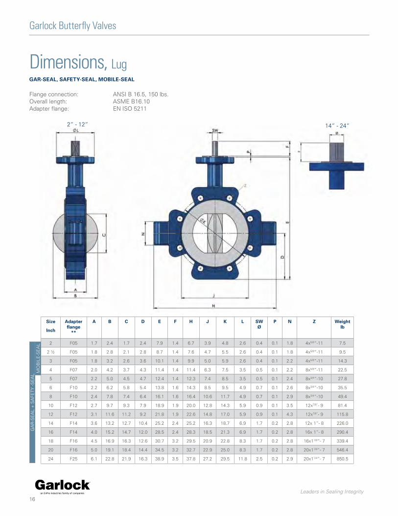
Dimensions, WaferGar-seal, safeTy-seal, mobile-seal
Flange connection:Overall length:Adapter flange:
ANSI B 16.5, 150 lbs.ASME B16.10EN ISO 5211
2“ - 12“ 14“ - 24“
size
inch
adapter flange
**
a b C d e f G h J k l sW Ø
p n Weight lb
2 F05 1.7 2.4 1.7 2.4 7.9 1.4 4.0 5.9 3.9 4.4 2.6 0.4 0.1 1.6 5.7
2 ½ F05 1.8 2.8 2.1 2.8 8.7 1.4 4.8 6.8 4.7 5.5 2.6 0.4 0.1 1.6 7.9
3 F05 1.8 3.2 2.6 3.6 10.1 1.4 5.2 7.2 5.0 5.9 2.6 0.4 0.1 1.6 8.9
4 F07 2.0 4.2 3.7 4.3 11.4 1.4 6.4 8.4 6.3 7.5 3.5 0.5 0.1 1.9 13.5
5 F07 2.2 5.0 4.5 4.7 12.4 1.4 7.6 9.8 7.4 8.5 3.5 0.5 0.1 1.9 18.9
6 F10 2.2 6.2 5.8 5.4 13.8 1.6 8.6 11.4 8.5 9.5 4.9 0.7 0.1 2.2 24.7
8 F10 2.4 7.8 7.4 6.4 16.1 1.6 10.8 13.8 10.6 11.7 4.9 0.7 0.1 2.2 36.2
10 F12 2.7 9.7 9.3 7.9 18.9 1.9 12.9 15.9 12.8 14.3 5.9 0.9 0.1 2.4 59.9
12 F12 3.1 11.6 11.2 9.2 21.8 1.9 14.9 17.9 14.8 17.0 5.9 0.9 0.1 2.8 79.6
14 F14 3.6 13.2 12.7 10.4 25.2 2.4 17.3 21.7 16.3 18.7 6.9 1.7 0.2 2.8 157.7
16 F14 4.0 15.2 14.7 12.0 28.5 2.4 19.3 22.4 18.5 21.3 6.9 1.7 0.2 2.8 196.7
18 F16 4.5 16.9 16.3 12.6 30.7 3.2 21.2 26.4 20.9 22.8 8.3 1.7 0.2 2.8 276.5
20 F16 5.0 19.1 18.4 14.4 34.5 3.2 23.4 27.2 22.9 25.0 8.3 1.7 0.2 2.8 346.9
24 F25 6.1 22.8 21.9 16.3 38.9 3.5 27.4 32.3 27.2 29.5 11.8 2.5 0.2 2.9 564.9
GA
R-S
EA
L +
SA
FETY
-SE
AL
MO
BIL
E-S
EA
L
Leaders in Sealing Integrity
Dimensions, LugGar-seal, safeTy-seal, mobile-seal
Garlock Butterfly Valves
Flange connection:Overall length:Adapter flange:
ANSI B 16.5, 150 lbs.ASME B16.10EN ISO 5211
2“ - 12“ 14“ - 24“
size
inch
adapter flange
**
a b C d e f h J k l sW Ø
p n Z Weight lb
2 F05 1.7 2.4 1.7 2.4 7.9 1.4 6.7 3.9 4.8 2.6 0.4 0.1 1.8 4x5/8“-11 7.5
2 ½ F05 1.8 2.8 2.1 2.8 8.7 1.4 7.6 4.7 5.5 2.6 0.4 0.1 1.8 4x5/8“-11 9.5
3 F05 1.8 3.2 2.6 3.6 10.1 1.4 9.9 5.0 5.9 2.6 0.4 0.1 2.2 4x5/8“-11 14.3
4 F07 2.0 4.2 3.7 4.3 11.4 1.4 11.4 6.3 7.5 3.5 0.5 0.1 2.2 8x5/8“-11 22.5
5 F07 2.2 5.0 4.5 4.7 12.4 1.4 12.3 7.4 8.5 3.5 0.5 0.1 2.4 8x3/4“-10 27.8
6 F10 2.2 6.2 5.8 5.4 13.8 1.6 14.3 8.5 9.5 4.9 0.7 0.1 2.6 8x3/4“-10 35.5
8 F10 2.4 7.8 7.4 6.4 16.1 1.6 16.4 10.6 11.7 4.9 0.7 0.1 2.9 8x3/4“-10 49.4
10 F12 2.7 9.7 9.3 7.9 18.9 1.9 20.0 12.8 14.3 5.9 0.9 0.1 3.5 12x7/8“- 9 81.4
12 F12 3.1 11.6 11.2 9.2 21.8 1.9 22.6 14.8 17.0 5.9 0.9 0.1 4.3 12x7/8“- 9 115.8
14 F14 3.6 13.2 12.7 10.4 25.2 2.4 25.2 16.3 18.7 6.9 1.7 0.2 2.8 12x 1“- 8 226.0
16 F14 4.0 15.2 14.7 12.0 28.5 2.4 28.3 18.5 21.3 6.9 1.7 0.2 2.8 16x 1“- 8 290.4
18 F16 4.5 16.9 16.3 12.6 30.7 3.2 29.5 20.9 22.8 8.3 1.7 0.2 2.8 16x11/8“- 7 339.4
20 F16 5.0 19.1 18.4 14.4 34.5 3.2 32.7 22.9 25.0 8.3 1.7 0.2 2.8 20x11/8“- 7 546.4
24 F25 6.1 22.8 21.9 16.3 38.9 3.5 37.8 27.2 29.5 11.8 2.5 0.2 2.9 20x11/4“- 7 850.5
GA
R-S
EA
L +
SA
FETY
-SE
AL
MO
BIL
E-S
EA
L
16
Leaders in Sealing Integrity
Garlock Butterfly Valves
17
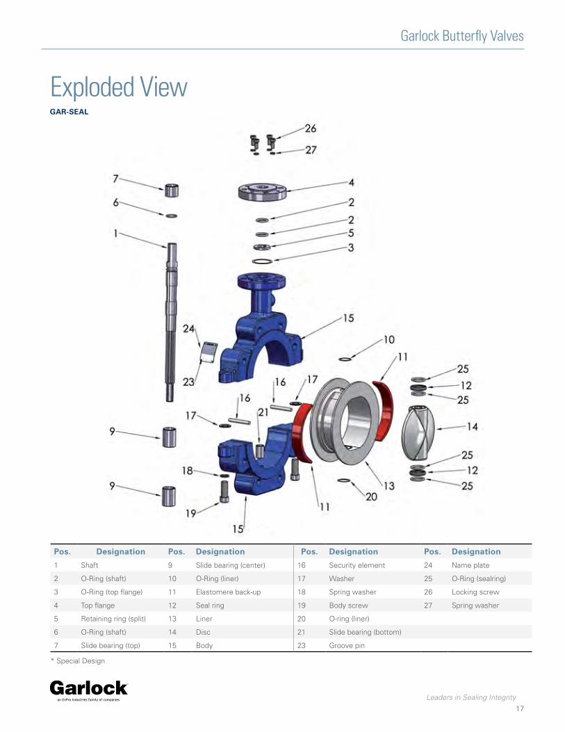
Exploded ViewGar-seal
pos. designation pos. designation pos. designation pos. designation
1 Shaft 9 Slide bearing (center) 16 Security element 24 Name plate
2 O-Ring (shaft) 10 O-Ring (liner) 17 Washer 25 O-Ring (sealring)
3 O-Ring (top flange) 11 Elastomere back-up 18 Spring washer 26 Locking screw
4 Top flange 12 Seal ring 19 Body screw 27 Spring washer
5 Retaining ring (split) 13 Liner 20 O-ring (liner)
6 O-Ring (shaft) 14 Disc 21 Slide bearing (bottom)
7 Slide bearing (top) 15 Body 23 Groove pin
* Special Design

Leaders in Sealing Integrity
STERILE-SEAL
Garlock Butterfly Valves
18
appliCaTionsSTERILE-SEAL valves are used where sterile processes need to be maintained in the pharmaceutical and food industries without unnecessary and costly overhauls and replacement. The special characteristic of this valve is its external sterilization capability. By the design of the valve the critical “dead“ areas of the valve, as well as the disc, body liner and seals, can be sterilized with steam without contact to the process.
dimensions » 2“ up to 16“
flanGe ConneCTion
» ASME B16.5 class 150 lbs (design RF/FF) » EN 1092 PN 10/16 (Design A/B)
– (Available upon request)
faCe-To-faCe dimensions » ISO 5752 Table 5 short » ASME B16.10
(2“ to 12“ Table Narrow 14“ to 24“ Table Wide) » DIN EN 558-1 GR 20 » MSS-SP 67
(2“ to 12“ Table Narrow 14“ to 24“ Table Wide) » API 609
(2“ to 12“ Category A 14“ to 24“ Category B)
body sTrenGTh » DIN/ EN 12516 T2 (DIN 3840) » tested within the scope of the inspection body designate
by Module H1
operaTinG pressure » 145 psi (depending on operating temperature)
TesTinG » EN 12266 P10 » EN 12266 P11 » EN 12266 P12 Leak rate A
bodies » Wafer and Lug design with long neck for insulation
VaCuum » up to 1 mbar abs. (depending on size and temperature)
TemperaTure ranGe » -40 °F up to +338 °F (depending on material)
head flanGe » EN ISO 5211 » NF E 29-402
liner » PTFE

Leaders in Sealing Integrity
STERILE-SEAL
Garlock Butterfly Valves
19
For fermentation, sterile processing is the premise to guarantee the optimum productivity of the microorganisms being used. All bacteria have to be destroyed before fermentation and also all products fed into the process have to be sterilized. Most important is the avoidance of any contamination during fermentation up to the separation of the biomass and treatment of the final product.
The new re-designed STERILE-SEAL valve with its steam blocking chambers surround and protect the product area against external pollution, even under vacuum conditions. This design is a major breakthrough for large scale biotechnology plants. With the STERILE-SEAL valve bacteria contamination is a thing of the past.
ConsTruCTionThe media in the inner chamber is protected against contamination by the surrounding isolation chambers which are directly connected to the inner sealing system. A second outer sealing system separates the process from the atmosphere. STERILE-SEAL valves are completely void and cavity-free to prevent any build-up of nutrients.
operaTion prinCiplePressurised steam is fed into the steam inlet and distributed through the longitudinal channels of the shaft and out through the flow control at the bottom of the valve body. It is also possible to seal the valve by pressuring the isolation chambersand closing the steam outlet connection.
sTeriliZaTion proof
During tests, STERILE-SEAL valves were contaminated at several points with Bacillus Stearothermophilus with a population of 5,7x10⁵. Pressurised steam was then allowed to flow through the two chambers, followed by sterile air. In every instance the bacillus was completely destroyed.
The safe ConCepT
STERILE-SEAL valves meet the highest standards of Garlock’s excellence.
baCTeria Won’T surViVe
for example:
body Split-body, manufactured from ductile iron, cast steel or stainless steel. Safety sealing between the two body halves, seals are fitted within the body liner to prevent atmospheric contamination and the escape of media.
Body liner manufactured from high density PTFE* FDA approved Void-free, impermeable, liner thickness 3 mm minimum.
sTainless sTeel disC For highest demands, i.e. pyrogenic resistant, particle and fibrous free surfaces with max. 1 % delta-ferrite, content: Forged (WN 1.4435 and others). Surface finishes to 0,1 μm Ra are available.
shafT One-piece manufactured from stainless steel with ring and longitudinal channels. The STERILE-SEAL concept improves the profitability of production processes in pharmaceutical, food and biotechnology industries.
adVanTaGes » Safety against contamination » Safety against corrosion » Safety of the body against over-pressurisation » Safety by standardization » Safety against leakages » Safety by identification

Leaders in Sealing Integrity
STERILE-SEAL
Garlock Butterfly Valves
20
PTFE*, isostatically molded. High density, high crystallinity, stainless steel discs. STERILE-SEAL valves are available in wafer and lug design in all sizes from 2“ to 16“. Actuators of any kind and type can be mounted.
serViCe pressure: serViCe TemperaTure:
2 Chamber sysTem GuaranTees produCT safeTy
From vacuum up to 145psi
40°F to 338°F (392°F**)
ShaftAtmospheric sealing system
Outer sealing system
Steam inlet
Ring channel
Blocking chamber (outer chamber)
Outer sealing system
Inner sealing system
Safety sealing
Inner sealing system
Outer sealing system
Blocking chamber (outer chamber)
Body
Body liner
Disc
Steam channels
Product chamber(inner chamber)
Steam outlet
* Polytetrafluoroethylene
** Please contact Garlock

Leaders in Sealing Integrity
21
Garlock Butterfly Valves
MaterialssTerile-seal
pos. Qty material designation pos. Qty material designation
1 1 1.4313 up to 12”1.4021 above 12”
Shaft 14 1 see material table Valve disc
15 1 s. table Body
2 24 EPDM O-ring (shaft) 16 2 PTFE security element
3 14 EPDM O-ring (top flange) 17 2 PTFE washer
4 1 1.4301 Top flange 18 2 Stainless Steel Spring washer
5 1 PTFE, carbon reinf. Retaining ring (split) 19 2 Stainless Steel Body Screw
6 14 EPDM O-ring (shaft) 20 14 EPDM O-ring (liner)
7 1 Steel/PTFE Slide bearing (top) 21 1 Steel/PTFE slide bearing (bottom)
8 1 GYLON® Fitting 22 1 Stainless Steel Fitting
9 2 Stainless Steel Slide bearing (center) 23 4 Stainless Steel Groove pin
10 14 EPDM O-ring (liner) 24 1 Stainless Steel Nameplate
11 24 EPDM Elastomer backup element 25 44 EPDM O-ring (sealring)
12 2 PTFE Sealring 26 4 Stainless Steel Locking screw
13 1 see material table Liner 27 4 Stainless Steel Spring washer
1 does not apply above 10”2 > 14” - 4 pc. each3 Special design4 other materials on request
Leaders in Sealing Integrity
22
Garlock Butterfly Valves
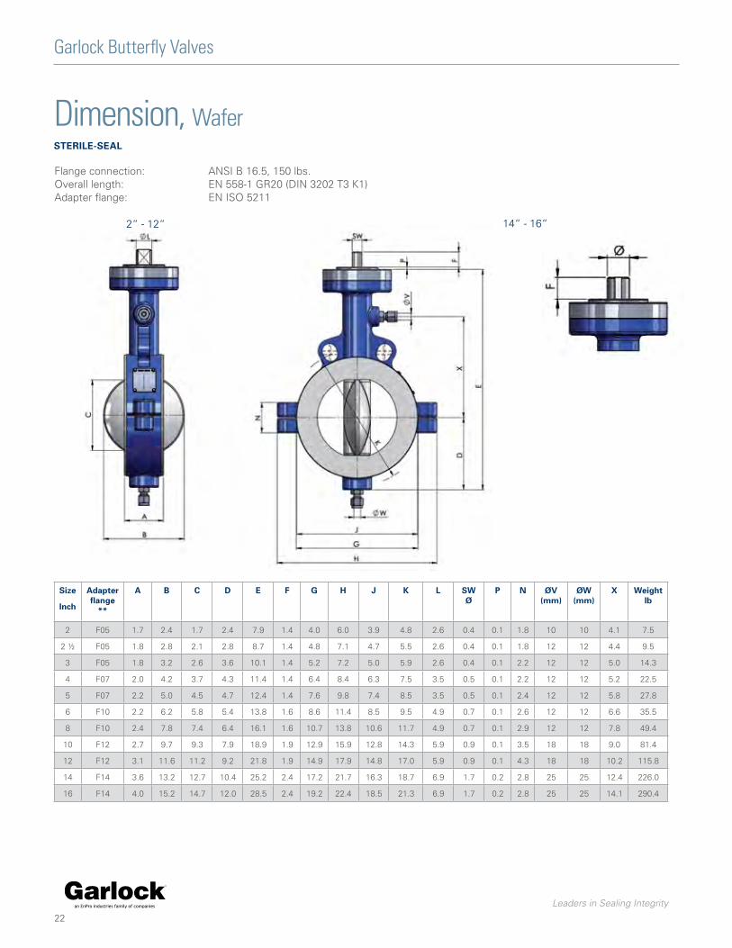
Dimension, WafersTerile-seal
Flange connection:Overall length:Adapter flange:
ANSI B 16.5, 150 lbs.EN 558-1 GR20 (DIN 3202 T3 K1)EN ISO 5211
2“ - 12“ 14“ - 16“
size
inch
adapter flange
**
a b C d e f G h J k l sW Ø
p n ØV(mm)
ØW(mm)
x Weight lb
2 F05 1.7 2.4 1.7 2.4 7.9 1.4 4.0 6.0 3.9 4.8 2.6 0.4 0.1 1.8 10 10 4.1 7.5
2 ½ F05 1.8 2.8 2.1 2.8 8.7 1.4 4.8 7.1 4.7 5.5 2.6 0.4 0.1 1.8 12 12 4.4 9.5
3 F05 1.8 3.2 2.6 3.6 10.1 1.4 5.2 7.2 5.0 5.9 2.6 0.4 0.1 2.2 12 12 5.0 14.3
4 F07 2.0 4.2 3.7 4.3 11.4 1.4 6.4 8.4 6.3 7.5 3.5 0.5 0.1 2.2 12 12 5.2 22.5
5 F07 2.2 5.0 4.5 4.7 12.4 1.4 7.6 9.8 7.4 8.5 3.5 0.5 0.1 2.4 12 12 5.8 27.8
6 F10 2.2 6.2 5.8 5.4 13.8 1.6 8.6 11.4 8.5 9.5 4.9 0.7 0.1 2.6 12 12 6.6 35.5
8 F10 2.4 7.8 7.4 6.4 16.1 1.6 10.7 13.8 10.6 11.7 4.9 0.7 0.1 2.9 12 12 7.8 49.4
10 F12 2.7 9.7 9.3 7.9 18.9 1.9 12.9 15.9 12.8 14.3 5.9 0.9 0.1 3.5 18 18 9.0 81.4
12 F12 3.1 11.6 11.2 9.2 21.8 1.9 14.9 17.9 14.8 17.0 5.9 0.9 0.1 4.3 18 18 10.2 115.8
14 F14 3.6 13.2 12.7 10.4 25.2 2.4 17.2 21.7 16.3 18.7 6.9 1.7 0.2 2.8 25 25 12.4 226.0
16 F14 4.0 15.2 14.7 12.0 28.5 2.4 19.2 22.4 18.5 21.3 6.9 1.7 0.2 2.8 25 25 14.1 290.4

Leaders in Sealing Integrity
23
Garlock Butterfly Valves
Dimension, LugsTerile-seal
Flange connection:Overall length:Adapter flange:
ANSI B 16.5, 150 lbs.EN 558-1 GR20 (DIN 3202 T3 K1)EN ISO 52112“ to 16“
2“ - 12“ 14“ - 16“
size
inch
adapter flange
**
a b C d e f h J k l sW Ø
p n ØV(mm)
ØW(mm)
Z x Weight lb
2 F05 1.7 2.4 1.7 2.4 7.9 1.4 6.0 3.9 4.8 2.6 0.4 0.1 1.8 10 10 4x5/8“-11 4.1 7.5
2 ½ F05 1.8 2.8 2.1 2.8 8.7 1.4 7.1 4.7 5.5 2.6 0.4 0.1 1.8 12 12 4x5/8“-11 4.4 9.5
3 F05 1.8 3.2 2.6 3.6 10.1 1.4 7.2 5.0 5.9 2.6 0.4 0.1 2.2 12 12 4x5/8“-11 5.0 14.3
4 F07 2.0 4.2 3.7 4.3 11.4 1.4 8.4 6.3 7.5 3.5 0.5 0.1 2.2 12 12 8x5/8“-11 5.2 22.5
5 F07 2.2 5.0 4.5 4.7 12.4 1.4 9.8 7.4 8.5 3.5 0.5 0.1 2.4 12 12 8x3/4“-10 5.8 27.8
6 F10 2.2 6.2 5.8 5.4 13.8 1.6 11.4 8.5 9.5 4.9 0.7 0.1 2.6 12 12 8x3/4“-10 6.6 35.5
8 F10 2.4 7.8 7.4 6.4 16.1 1.6 13.8 10.6 11.7 4.9 0.7 0.1 2.9 12 12 8x3/4“-10 7.8 49.4
10 F12 2.7 9.7 9.3 7.9 18.9 1.9 15.9 12.8 14.3 5.9 0.9 0.1 3.5 18 18 12x7/8“- 9 9.0 81.4
12 F12 3.1 11.6 11.2 9.2 21.8 1.9 17.9 14.8 17.0 5.9 0.9 0.1 4.3 18 18 12x7/8“- 9 10.2 115.8
14 F14 3.6 13.2 12.7 10.4 25.2 2.4 21.7 16.3 18.7 6.9 1.7 0.2 2.8 25 25 12x 1“- 8 12.4 226.0
16 F14 4.0 15.2 14.7 12.0 28.5 2.4 22.4 18.5 21.3 6.9 1.7 0.2 2.8 25 25 16x 1“- 8 14.1 290.4

Leaders in Sealing Integrity24
Garlock Butterfly Valves
Exploded ViewsTerile-seal
pos. designation pos. designation pos. designation pos. designation
1 Shaft 8 Fitting 15 Body 22 Fitting
2 O-Ring (shaft) 9 Slide bearing (center) 16 Security element 23 Groove pin
3 O-Ring (top flange) 10 O-Ring (liner) 17 Washer 24 Name plate
4 Top flange 11 Elastomere back-up 18 Spring washer 25 O-Ring (sealring)
5 Retaining ring (split) 12 Seal ring 19 Body screw 26 Locking screw
6 O-Ring (shaft) 13 Liner 20 O-ring (liner) 27 Spring washer
7 Slide bearing (top) 14 Disc 21 Slide bearing (bottom)
* Special Design
Leaders in Sealing Integrity
25
Garlock Butterfly Valves
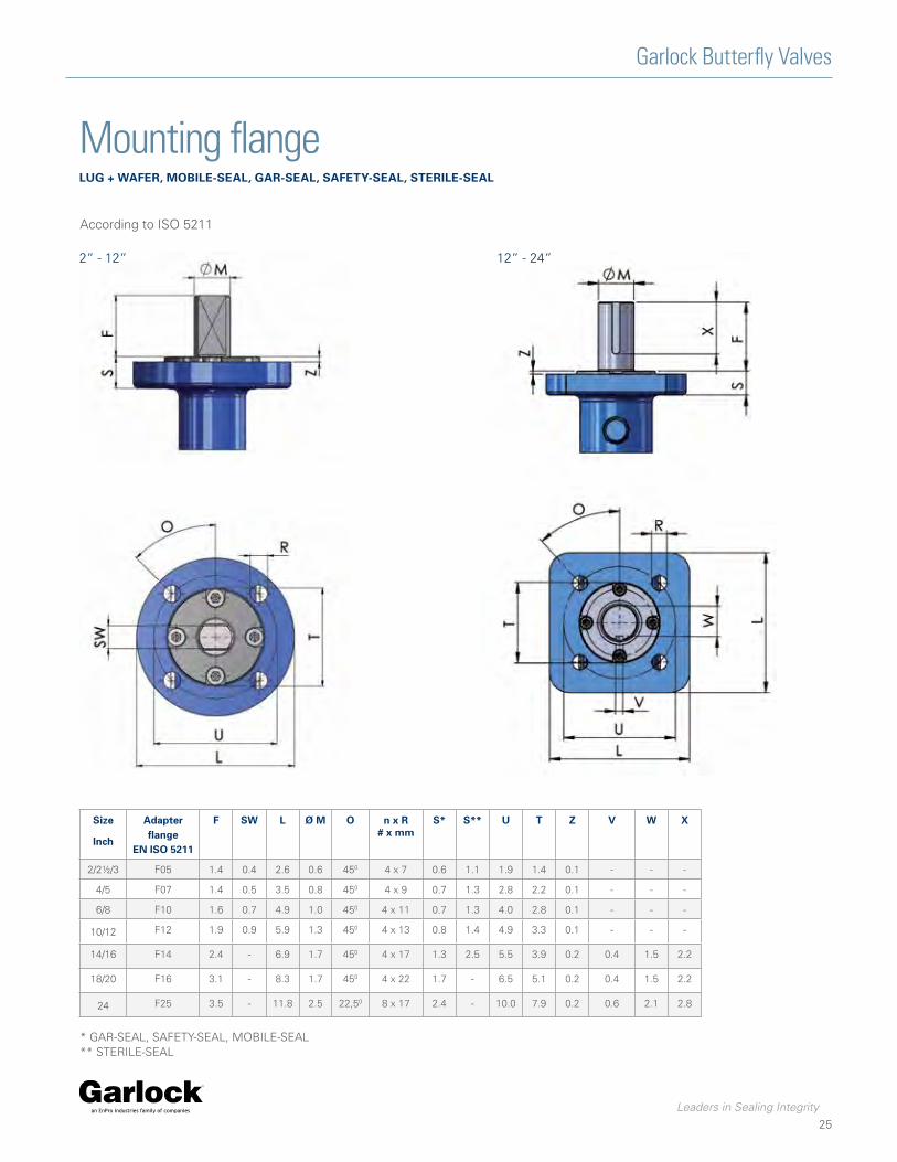
Mounting flangeluG + Wafer, mobile-seal, Gar-seal, safeTy-seal, sTerile-seal
* GAR-SEAL, SAFETY-SEAL, MOBILE-SEAL** STERILE-SEAL
size
inch
adapter flange
en iso 5211
f sW l Ø m o n x r# x mm
s* s** u T Z V W x
2/2½/3 F05 1.4 0.4 2.6 0.6 450 4 x 7 0.6 1.1 1.9 1.4 0.1 - - -
4/5 F07 1.4 0.5 3.5 0.8 450 4 x 9 0.7 1.3 2.8 2.2 0.1 - - -
6/8 F10 1.6 0.7 4.9 1.0 450 4 x 11 0.7 1.3 4.0 2.8 0.1 - - -
10/12 F12 1.9 0.9 5.9 1.3 450 4 x 13 0.8 1.4 4.9 3.3 0.1 - - -
14/16 F14 2.4 - 6.9 1.7 450 4 x 17 1.3 2.5 5.5 3.9 0.2 0.4 1.5 2.2
18/20 F16 3.1 - 8.3 1.7 450 4 x 22 1.7 - 6.5 5.1 0.2 0.4 1.5 2.2
24 F25 3.5 - 11.8 2.5 22,50 8 x 17 2.4 - 10.0 7.9 0.2 0.6 2.1 2.8
According to ISO 5211
2“ - 12“ 12“ - 24“
Leaders in Sealing Integrity
26
Garlock Butterfly Valves
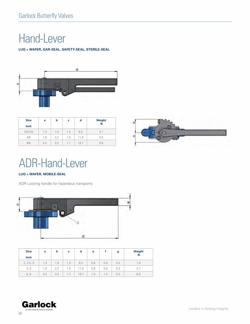
Hand-LeverluG + Wafer, Gar-seal, safeTy-seal, sTerile-seal
size
inch
a b c d Weight lb
2/2½/3 1.3 1.8 1.5 8.3 3.1
4/5 1.8 2.2 1.5 11.8 4.5
6/8 3.2 3.2 1.7 19.7 5.6
ADR-Hand-LeverluG + Wafer, mobile-seal
ADR Locking handle for hazardous transports
size
inch
a b c d e f g Weight lb
2, 2½, 3 1.3 1.8 1.5 8.3 0.8 0.8 0.3 1.9
4, 5 1.8 2.2 1.5 11.8 0.8 0.8 0.3 2.7
6, 8 3.2 3.2 1.7 19.7 1.0 1.0 0.3 6.8

Leaders in Sealing Integrity27
Garlock Butterfly Valves
Gear OperatorluG + Wafer, Gar-seal, safeTy-seal, mobile-seal, sTerile-seal
size
inch
f g h i k* l* k** l** m n Gross weight (lb)
Typ W Wafer Typ l lug
2 2.4 1.8 3.5 1.5 6.6 7.8 7.1 8.3 5.9 4.9 14.6 16.3
2½ 2.4 1.8 3.5 1.5 6.6 8.2 7.1 8.7 5.9 4.9 16.8 18.3
3 2.4 1.8 3.5 1.5 7.5 8.8 8.0 9.1 5.9 4.9 17.6 23.2
4 2.4 1.8 3.5 1.5 8.1 9.4 8.7 10.0 5.9 4.9 22.3 31.3
5 2.4 1.8 3.5 1.5 8.7 9.9 9.3 10.6 5.9 4.9 27.8 36.6
6 3.3 2.3 4.6 2.0 9.8 11.1 10.4 11.7 7.2 9.8 39.7 50.5
8 3.3 2.3 4.6 2.0 11.0 12.3 11.6 12.9 7.2 9.8 51.2 64.4
10 4.1 2.9 5.9 2.6 12.7 14.2 13.3 14.8 8.5 11.8 84.2 105.6
12 4.1 2.9 5.9 2.6 14.3 15.8 14.8 16.4 8.5 11.8 103.9 140.0
14 5.2 3.4 7.8 3.5 16.7 18.4 17.9 19.6 11.1 17.8 196.3 264.6
16 5.2 3.4 7.8 3.5 18.5 20.2 19.7 21.4 11.1 17.8 235.3 328.9
18 7.0 4.5 9.9 4.8 20.1 22.3 - - 13.2 17.8 336.0 398.9
20 7.0 4.5 9.9 4.8 22.0 6.3 - - 13.2 17.8 406.4 605.9
24 8.2 4.6 12.4 6.1 24.6 27.6 - - 14.2 17.8 637.7 943.1
* GAR-SEAL, SAFETY-SEAL, MOBILE-SEAL** STERILE-SEAL
Leaders in Sealing Integrity
28
Garlock Butterfly Valves
Technical DataGar-seal, safeTy-seal, mobile-seal, sTerile-seal
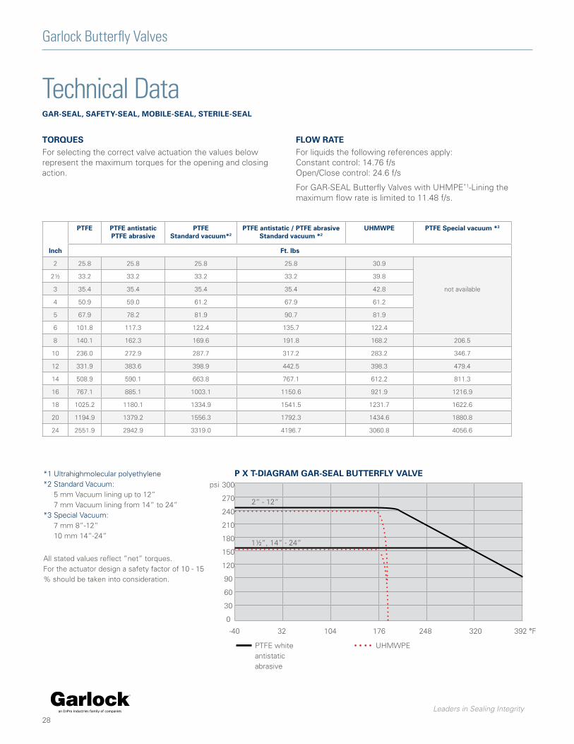
pTfe pTfe antistaticpTfe abrasive
pTfestandard vacuum*2
pTfe antistatic / pTfe abrasivestandard vacuum *2
uhmWpe pTfe special vacuum *3
inch ft. lbs
2 25.8 25.8 25.8 25.8 30.9
2½ 33.2 33.2 33.2 33.2 39.8
3 35.4 35.4 35.4 35.4 42.8 not available
4 50.9 59.0 61.2 67.9 61.2
5 67.9 78.2 81.9 90.7 81.9
6 101.8 117.3 122.4 135.7 122.4
8 140.1 162.3 169.6 191.8 168.2 206.5
10 236.0 272.9 287.7 317.2 283.2 346.7
12 331.9 383.6 398.9 442.5 398.3 479.4
14 508.9 590.1 663.8 767.1 612.2 811.3
16 767.1 885.1 1003.1 1150.6 921.9 1216.9
18 1025.2 1180.1 1334.9 1541.5 1231.7 1622.6
20 1194.9 1379.2 1556.3 1792.3 1434.6 1880.8
24 2551.9 2942.9 3319.0 4196.7 3060.8 4056.6
TorQuesFor selecting the correct valve actuation the values below represent the maximum torques for the opening and closing action.
floW raTeFor liquids the following references apply:Constant control: 14.76 f/sOpen/Close control: 24.6 f/s
For GAR-SEAL Butterfly Valves with UHMPE*1-Lining the maximum flow rate is limited to 11.48 f/s.
PTFE white antistatic abrasive
300
270
240
210
180
150
120
90
60
30
0
psi
-40 32 104 176 248 320 392 °F
2“ - 12“
1½“, 14“ - 24“
p x T-diaGram Gar-seal buTTerfly ValVe
UHMWPE
*1 Ultrahighmolecular polyethylene*2 Standard Vacuum: 5 mm Vacuum lining up to 12“ 7 mm Vacuum lining from 14“ to 24“ *3 Special Vacuum: 7 mm 8“-12“ 10 mm 14“-24“
All stated values reflect ”net” torques.For the actuator design a safety factor of 10 - 15 % should be taken into consideration.

Leaders in Sealing Integrity
-40 32 104 176 248 320 392 °F
29
Garlock Butterfly Valves
Technical DataGar-seal, safeTy-seal, mobile-seal, sTerile-seal
open/Close ConTrol - CharaCTerisTiC CurVeThe graph shows the percentage flow rate, depending upon the disc-aperture. The curve reflects a throttle valve of any size with slight modifications depending upon thickness and profile of the disc itself. Throttle valves with apertures above 60° should be used for on/off control only.
ConTinuous ConTrol/CharaCTerisTiC CurVeFor continuous control of a throttle valve the flow rate for a 60° aperture is defined with 100 % to provide a flow reserve. The graph has a characteristic of similar percentage for disc opening from 0° to 60°.
anGle of aperTure
10 20 30 40 50 60 70 80 90 100
10 20 30 40 50 60 70 80 90 100
Flow rate in %
anGle of aperTure
Flow rate in %
900
800
700
600
500
400
300
200
100
00
600
500
400
300
200
100
00
nominal bore cv-factor against the angle of aperture
inch 20% 30% 40% 50% 60% 70% 80% 90%
2 1 15 29 43 63 80 94 97
2½ 2 19 39 60 95 130 151 153
3 2 19 44 93 154 222 282 283
4 10 50 101 167 265 367 463 487
5 19 71 142 244 304 577 777 824
6 26 131 249 422 635 954 1128 997
8 41 191 385 644 1014 1409 1779 1871
10 75 349 705 1177 1855 2576 3254 3422
12 111 517 1044 1745 2748 3818 4822 5070
14 158 733 1481 2474 3898 5416 6839 7192
16 225 1042 2130 3511 5533 7686 9708 10208
18 275 1273 2569 4290 6756 9390 11859 12470
20 345 1597 3226 5387 8488 11793 14893 15660
24 487 2260 4565 7621 12008 16683 21070 22156
CV-Values aGainsT The anGle of aperTureThe cv-factor reflects the flow of water (density 1=1000 kg/m3) in gpm for a pressure gradient ofp= 1 psi. The resistance characteristic of the butterfly valve is subject to the cv-factor. It replaces all earlier definitions, see cross-section, flow and friction coefficient. A detailed butterfly valve dimensioning for maximum flow and/or for throttle use is performed by CONVAL-Software programming. Please consult Garlock directly.

Leaders in Sealing Integrity
30
Garlock Butterfly Valves
Special Vacuum DesignGarloCk ValVes WiTh speCial VaCuum resisTanT liners
GarloCk ValVes haVe for deCades operaTed under exTreme VaCuum CondiTionsPast statements on vacuum stress have been made and documented, but only at ambient temperature and the valve closed. This is very ambiguous to a plant engineer. Their requirements are the actual vacuum data at all temperatures. Plant vacuum can go down to 1 mbar together with higher temperatures. This often leads to leakages and malfunctions as the liner can deformed. Garlock has developed special vacuum versions of its GAR-SEAL valves to meet these particular demands.
Vacuum applications of fluorocarbon lined valves with separate liners are subject to special parameters. Therefore not only the actual vacuum is important, but also the service temperature, the thickness of the liner and its geometry.
TesT proCedure To deTermine VaCuum suiTabiliTy
Typical appearance of high vacuum-loaded Body Liner
Garlock with its successful development program and substantial testing of various sizes, including 20“, at temperatures up to 392°F concluded that such extreme service conditions can be handled.
GAR-SEAL Valves can be supplied with varying liner thicknesses for vacuum duties.
The 4“ size liners show the difference between the standard 3 mm thick and the vacuum 5 mm thick liners. The liner thickness substantially improves the performance against high vacuum stress.
In the 4“ valve the 3 mm thick liner will operate to 1 mbar, while the 5 mm liner operates below 1 mbar vacuum. Depending on the operating vacuum and temperature and size of valve, the liner thickness can be calculated and selected between 3 mm and 10 mm for GAR-SEAL valves.
Please contact Garlock directly for your specific requirements on vacuum applications.
Vacuum pump
Vacuum meter
Temperature indicator
Environmental chamber
Sight glass
Valve
Temperature range:Temperature increments:
-24°F to 392°FΔt: 6.4°F
3mm vacuum liner 5mm vacuum liner
Leaders in Sealing Integrity
31
Garlock Butterfly Valves
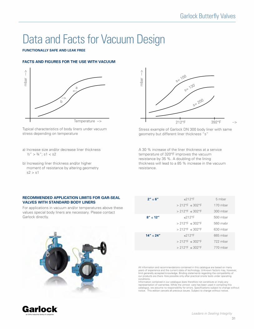
Data and Facts for Vacuum DesignfunCTionally safe and leak free
faCTs and fiGures for The use WiTh VaCuum
Typical characteristics of body liners under vacuum stress depending on temperature
Stress example of Garlock DN 300 body liner with same geometry but different liner thickness “s”
mba
r
-->Temperature -->
a
b
212°F
s= 100
s= 130
s= 200
--->
mba
r
-->
<--
--->
392°F
a) Increase size and/or decrease liner thickness ½“ > ¾“; s1 < s2
b) Increasing liner thickness and/or higher moment of resistance by altering geometry s2 > s1
A 30 % increase of the liner thickness at a service temperature of 320°F improves the vacuum resistance by 35 %. A doubling of the lining thickness will lead to a 85 % increase in the vacuum resistance.
reCommended appliCaTion limiTs for Gar-seal ValVes WiTh sTandard body linersFor applications in vacuum and/or temperatures above these values special body liners are necessary. Please contact Garlock directly.
2“ ≤ 6“ ≤212°F 5 mbar
> 212°F ≤ 302°F 170 mbar
> 212°F ≤ 302°F 300 mbar
8“ ≤ 12“ ≤212°F 500 mbar
> 212°F ≤ 302°F 560 mabr
> 212°F ≤ 302°F 630 mbar
14“ ≤ 24“ ≤212°F 665 mbar
> 212°F ≤ 302°F 722 mbar
> 212°F ≤ 302°F 770 mbar
All information and recommendations contained in this catalogue are based on many years of experience and the current state of technology. Unknown factors may, however, limit generally accepted knowledge. Binding statements regarding the compatibility of our products are there -fore possible only after practical onsite tests under operating conditions.Information contained in our catalogue does therefore not constitute or imply any representation of warrantee. While the utmost care has been used in compiling this catalogue, we assume no responsibility for errors. Specifications subject to change without notice. This edition cancels all previous issues. Subject to change without notice.

Tel: 1-877-GARLOCK / 315.597.4811 Fax: 800.543.0598 / 315.597.3216www.garlock.com
GARLOCKan EnPro Industries family of companies
Garlock Sealing TechnologiesGarlock Rubber TechnologiesGPTGarlock PTYGarlock do Brasil
Garlock de Canada, LTDGarlock ChinaGarlock SingaporeGarlock GermanyGarlock India Private Limited
Garlock de Mexico, S.A. De C.V.Garlock New ZealandGarlock Great Britain LimitedGarlock Middle East
BV 1:1