
Garfield County, Colorado
41
" . . • .. .t7 ., ,. . . ·; ) ) .· .. . . ,.:··--,;· .. .. . .. .. ·. · .. 3
Transcript of Garfield County, Colorado

" . . ~. ~. • .. .t7 ., ,. . . ·;
)
) . · .. :.~ .
. ,. : ··--,;· .... ·~ ... .. ·. · ..
3

4


DeTect Inc. )~\) dotcct10n technologies ~~ )t--
1902 Wilson Avenue Panama City, Florida 32405 USA
T 850. 763.7200 F 850.763.0920 www.DeTect -inc.com
Aircraft Birdstrike Avoidance Radars - Avian Radar Systems - Security Radar Systems- Bird Control Systems - Radar Wind Pro filers
November 2, 2010
Kevin McDowell Water Systems Engineer SRBU - N. Piceance Encana Oil & Gas (USA) Inc. 370 17th Street, Suite 1700 Denver, CO 80202
(0) 720.876.5836 M) 303.968.9658 (F) 720.876.6836 (E) Kevin [email protected]
RE: MERLIN detect & deter Bird Control Radar System Letter of Operational Status Encana Middle Fork Facility near Parachute, CO
Dear Mr. McDowell :
Merlin ,-f .. AVIAN RADAR SYSTEMS
via e-mail, 2 pages total
Pursuant to your request, please find below a summary of the operational status of MERLIN detect & deter Bird Control Radar System ("MERLIN" or "the system") installed and operating at the Encana Middle Fork Facility near Parachute, Colorado. The MERLIN system is an automated bird control system that uses the same advanced, proven military-grade bird radar technology DeTect developed for the US Air Force and NASA to reliably detect and track birds at extended ranges, monitor user-defined control zones, and, automatically activate bird deterrent devices to effectively and humanely harass and prevent birds from entering restricted areas such as industrial facility waste impoundments (see http://www.detect-inc.com/other.html for additional information).
1. Under contract to Encana, DeTect designed and manufactured the Middle Fork MERLIN system and supervised the installation at the Middle Fork radar facility in 2009.
2. The system was installed and has been operated since startup in accordance with DeTect's specifications and recommendations.
3. The unit is operating as designed and is monitored by DeTect remotely on a da ily basis . DeTect also makes periodic site visits to the site to verify operational status and system efficacy. . . .
4. To DeTect's knowledge, no migratory bird takes have occurred or been reported at the facility since the installation of the system.
Page 1 of 2

Encana Oil & Gas (USA) Inc. MERLIN detect & deter Bird Control Radar at Encana Middle Fork Facility November 2, 2010
DeTect Inc. \\\lc_ delcchon tec.t)f'I<Jk:XJ cs }JJr-
If you have any questions or require additional information, please do not hesitate to contact me at your convenience.
Sincerely,
DeTect, Inc.
~~ Gary W. Andrews General Manager & CEO
Cc: Jared Quillen Doug McElwain Edward Zakrajsek
Page 2 of 2

n
)
_)


)
LRAD-1 OOOX™
Operations Manual 9 G
Syste111. Deployntent and Maintenance
Copyright© 2007 American Technology Coxporation 104780-01 RevX2

Table of Contents
Table of Contents ...................................................................................................................... .. .. .... i
Important Safety Precautions ........................................................................................................................ I
System Description ........................................................................................................................................ 2
System Modules .......................................................................................................................................... 2
Head Unit .................................................................................................................................................... 2
Amplifier Pack ............................................................................................................................................ 4
System Setup .................................................................................................................................................. 5
Operation- Hailing and Warning .................................................................................................................. 7
Operation- Prerecorded Messages ............................................................................................................... 9
Care and Maintenance ................................................................................................................................. I 0
Troubleshooting and Repairs ....................................................................................................................... 12
Spare Parts/Support ..................................................................................................................................... 15
Specifications ............................................................................................................................................... 17
---------:--_;_ --=I

Important Safety Precautions The LRAD-1 OOOX is capable of producing sound pressure levels that have the potential to cause temporary or p ermanent hearing damage . Always follow the safety precautions described in this manual as well as on the unit' s interfaces.
The following conventions apply in this manual. Please note the warnings and take adequate measures to ensure safe operation of the unit.
Important Safety Instructions.
Risk of electric shock.
n Hearing Protection Required.
1. Read these instructions.
2. Keep these instructions in a place known to and accessible by the potential operators of the LRADlOOOX.
3 . Heed all warnings contained in this document.
} 4. Follow all instructions detailed in this document.
5 . Install in accordance with the instructions contained in this document.
6. Do not install near any heat sources such as radiators, heat registers, stoves, or other apparatus (including some electronics) that produce heat.
7 . Do not connect or disconnect any cables to the unit while the primary circuit is live unless the area is known to be non-hazardous.
8. Do not defeat the safety purpose of the polarized or grounding-type plug. A polarized plug has two blades with one wider than the other. A grounding type plug has two blades and a third grounding prong.
9. The wide b lade or the third prong is provided for your safety. If the provided plug does not fit into your outlet, consult an electric ian for replacement of the obsolete outle t.
10. Protect the power cord from being tread upon, excessively bent, creased, or p inched particularly at plugs, convenience receptacles, and the point where the cable assemblies connect to the apparatus.
11. Only use attachments/accessories specified by the manufacturer.
12. Unplug this apparatus during lightning storms or when unused for long periods of time.
13. Refer all servicing to qualified service personnel. Servicing is required when the LRAD-lOOOX has
been noticeably or substantially damaged in any way, including cord or plug damage, seriously
- 1 -

dented or breached housings, or if liquid has penetrated the interior of the device, or any accessories.
14. The LRAD-1 OOOX power cord shall be connected to a main socket outlet with a protective ground connection .
16. Do not b lock airflow through the fans on the e lectronics module .
16. Do no t open in hazardous locations or areas .
System Description The LRAD-1 OOOX consists of two principal modules and ancillary e quipment such as input devices, interface cables, and mounts.
SyFtem. Modules The two main modules are the Head Unit and the Amplifier Pack.
Head Unit The Head Unit houses ATC's highly directional acoustic drivers . This module emits high powered, directional acoustic energy at a target or targets. It is fitted with mounting points for the attachment of a yoke which allows for manual adjustment of azimuth and elevation orientations when used in conjunction with an approved mounting device or stand, such as ATC's tripod or ship rail mount. The Head Unit can be aimed by an operator using the included re movable rear handles.
- 2 -
)
)

~------------- --------------------
1
-~
I ---------
'"i
---- ,_
- ------------ --
I . l't•l -~ 'r Jll - }--'·
Alignment sights (2X)
!Figure I: LRAD-1 OOOX Head Uni~
- 3-

n: L lif' er "?c c {
The Amplifier Pack houses ATC's amplifier modules , power supply, and control interfaces . This module is conta ined in a wate rproof case and conta ins a ll interfaces and controls needed to transmit inte llig ible and clearly d iscernible communications and warning s ig na ls through the He ad Unit.
Cooling Fans __ .--
Signal Out to
Head Unit ---r
Volume Control
Limit Switch
!Figure 2: LRAD-1 OOOX Amplifier Pack Interface s!
Hour M eter
Main Power
Switch
A/C Power Input
The Head Unit can be deployed on mounts fitted with a 1-5/ 8" socket, such as ATC's rugged tripod or stainless steel ship-rail mount.
The LRAD-lOOOX ships with a handheld microphone and a digital recording/playback device for live speech communications and playback of pre-recorded messages and warning tones.
A 100 foot cable connects the Head Unit to the Amplifier Module and is included with the unit. A 50 foot AC power cord a lso ships with the unit. Contact your ATC representa tive to request custom cable le ngths.
- 4 -
)

)
System Setup Install handles in the rear of the Head Unit by sliding into the keyhole receptacles. Lock the handles in p lace by turning the locking sp r ing pin.
Install Yoke into tripod or ship-rail mount receptacle. Install unit in Yoke as shown in the following figures.
Tighten tilt-lock
knobs .
I A\ WARNING: The LRAD-1 o;ox weighs approxima:ely 9S lbs. This is a two-man lift.

,-----------------------------------------------------------------------
& WARNING: Do not hot plug the input/output connections, including the MIC, the MP3 and the Speaker Out connections.
1. Connect the microphone and/or MP3 player connections.
2. Connect the Speaker out cable to the Amplifier pack and the Head Unit.
3 . Connect AC Power Input connector to Amplifie r pack.
4. & WARNING: Ensure the volume control is a t the lowe st se tting b efore powering up the unit.
n Hearing protection must b e worn when op erating the unit. Personnel in the immediate vicinity of the Head Unit m ust wear hearing protec tion such as foam earplugs.
Power on the unit. The Powe r LED will illuminate a green light whe n the unit is ready for oper a tion.
To g e nerate a test signal, use the handhe ld microphone or MP3 player. Carefully adjust the volume control until the desired volume leve l is attained.
- 6 -
)

!operation - Hailing and :arning )
)
{) HEARING PROTECTION REQUIRED: Personnel ope rating the LRAD-lOOOX shall , a t a minimum, wear single earplug style hearing protection. The LRAD-1 OOOX is capab le of acoustic sound pressure levels in excess of OSHA noise hazard levels. As with any high-energy acoustic device , proper usage will minimize risk of hearing loss to the ope rator and personnel in its immediate vicinity .
{) PROTECTION OF NEARBY PERSONNEL: Qualified LRAD-lOOOX op erators must ensure the
device is positioned, aimed and ope rate d in a manne r so as to avoid exposing nearby p e rsonnel and bystanders to excessive sound pressure leve ls . The following guidelines are to be used in conjunction with sound judgment:
• Never operate LRAD-1 OOOX at maximum power where pe rsonnel may be within 75 me te rs or whe re an acoustically r efle ctive object, e.g. building, wall, or bulkhead, is locate d such that the reflected distance to personnel is less than 75 meters.
• Never point LRAD-lOOOX dire ctly at personnel in the immediate vicinity of operating position.
• Be advised that the output powe r of the warning tone is slightly higher than voice leve ls .
Many factors must b e considered whe n positioning the LRAD-1 OOOX for hailing and warning operations. The LRAD-lOOOXX Operations Zones shown in Figure 3 must always be taken into account to e nsure that personne l are not exposed to excessive sound pressure levels.
Factors to conside r when placing the LRAD-lOOOX include , but are not limite d to, the following:
All long-range communication devices should have an unobstructed transmission path to the anticipate d areas in which it will be aimed . Eve n small mast antennas may reflect some sound e nergy decreasing the effe ctiveness of the unit as we ll a s increasing refle cted noise leve ls for the operator and others nearby.
Placeme nt should be chosen so as to minimize or avoid transmission over decks or balconies where personnel may be located .
Shipboard operations should place the LRAD-l OOOX as close to the ship's sides, bow, or stern as possib le.
When choosing a placement area to maximize unob structe d transmission path(s), care must be taken to e nsure the LRAD-1 OOOX does not collide with any structures or equipment, nor encroach on personnel passageways when the unit is pivote d and manipulated through its full range of motion.
- 7 -

FRONT
BACK
L = LIMITED POWER M = MAXIMUM POWER
DO NOT ENTER WITHIN 15 METERS DURING CONTINUOUS OPERATION
DO NOT ENTER WITHIN 75 METERS DURING CONTINUOUS OPERATION
DO NOT ENTER DURING CONTINUO US OPERATION WITHOUT HEARING PROTECTION'
DO NOT ENTER DURING CONTINUOUS OPERATION WITHOUT HEARING PROTECTION'
SAFE FOR CONTINUOUS OPERATION
SAFE FOR CONTINUOUS OPERATION WITH HEARING PROTECTION'
' NOTE: HEARING PROTECTION MUST PROVIDE GREATER THAN 20 dB OF NOISE REDUCTION. DISPOSABLE SOFT FOAM EARPLUGS MAY BE USED AS HEARING PROTECTION.
!Figure 3: LR.AD-1 OOOX Safety Diagramj
The LRAD-lOOOX can be freely rotated to the left and right by loosening the T-handle a t the base of the mount and using the large handles on the back of the unit. Re-tightening the T-handle locks the device in the new position. To pivot the LRAD-1 OOOX up and down, loose n both of the handles on the sides of the unit just enough to be able to rotate the device, but maintaining a small amount of friction. This enables the user to maintain easy control of the vertical movement.
The LRAD-lOOOX can be accurately aimed at the vehicle or personnel the operator is attempting to communicate with using one of the two attached visual sighting devices. The sites are located on the le ft and r ight sides of the LRAD-lOOOXX at approximately the 9 o'clock and 3 o 'clock positions. The operator simply looks through the hole on the sight and alig ns the targe t in the cross hairs.
NOTE: The LRAD- 1000 audio transmission is very directional. It may be necessary to make aiming corrections for strong crosswinds when communicating over long distances. It may also be necessary to align the sights using spacer washers to e nsure the LRAD is being aimed accurately.
{) & WARNING: Hearing Protection: The LRAD-1000X sound projection is very directional. Operators standing behind the unit hear only a small fraction of the sound energy being transmitted. This can make the operator think the LRAD-1000X is not producing the required output. OPERATORS SHOULD NOT ATTEMPT TO LISTEN TO THE OUTPUT FROM THE FRONT OF THE DEVICE! HEARING DAMAGE MAY RESULT FROM SUCH ACTION.
- 8 -
)
)

)
jFigure 4: Do not attempt to listen to the output side of the unit.l
Operation - Prerecorded Messages American Technology Corporation recommends the use of prerecorded messages whenever possible. Prerecording ensures that messages are appropriately worded and clearly broadcasted to maximize effective communication.
The LRAD-lOOOX is supplied with a case hardened MP3 player. This MP3 player allows operators to utilize approved prerecorded messages in the field. Some operators have found it useful to record a message in several different languages to meet their communication needs. The MP3 player is preloaded with a number of warning and test messages that may be freely used/deleted as needed.
The MP3 player output cord is connected to the back of the LRAD-lOOOX through the MP3 INPUT port. Power is provided to the MP3 player from the LRAD-1 OOOX.
The MP3 player has two ports to either side of the output cable . One is labeled USB and is used with the supplied USB cable to download prerecorded audio files. The other jack is lab ele d Audio Input. It allows another accessory device such as the Phraselator to be connected through the MP3 playe r.
Note : There are 2 audio input jacks on the LRAD-lOOOX, one labeled MP3 INPUT and the other labeled MIC INPUT. Neither input has priority over the other. If broadcasting a recorded message through the MP3 INPUT port and the operator prefers to use the microphone, the MP3 player should first be put into the STOP mode. Failure to do so
- 9-
C>

will broadcast both the MP3 messag e and the spoken message through the LRAD-lOOOX at the same time.
Audio File P laybaclt:
1. Stop inputs from other audio input devices
2. Selec t the desired track with the FF or REW buttons.
3. Press PLAY to p lay the message.
4. The message will automatically repeat until the STOP button is depressed.
Using the Tone Generator:
& wARNING: The Tone Generator produces the loudest output from the LRAD- lOOOX. Qualified personnel must ensure the area in front of the LRAD-1 OOOX is clear for 7 5 meters in front of the d evice before activating the tone in MAXIMUM mode and 15 meters in LIMITED mode.
The MP3 Player has a tone generator located on the side. Press once for activation; press again for deactivation. The tone generator produces intense, pulsating warning tones.
ATC recommends using the tone in 2-5 second bursts for maximum effectiveness when hailing a subject. The tone will override the recorded voice transmission.
Other MP3 Player Functions:
The LRAD MP3 Player features a brightnes level button that will cycle the button and LCD brightness through 3 levels, including off. This is useful in compensating for glare and to avoid light signature when necessary.
Please see the LRAD MP3 Player Operating Manual for other functions and features of the MP3 player.
Care and Maintenance The LRAD-lOOOX is an all-weather hailing and warning device that requires minimal maintenance. As with any equipment, proper care and maintenance will ensure a long and useful life.
Clean LRAD- lOOOX and inspect for wear or other damage daily. Ensure that all fastening hardware is kept tight and all e lectrical connections secure and damage-free. Fasteners or o ther hardware or equipment that becomes loose may represent a serious hazard to personnel as well as the LRAD- l OOOX and nearby equipme nt.
Use non-fl ammable cleaning solutions with clean rags to wipe the exterior surfaces of the LRAD- lOOOX. The LRAD- lOOOX Head Unit can be sprayed down with fresh water to remove salt and dust buildup. The status LED window can be cleaned with soap and water. For corrosion control in sea applications, apply anti-corrosion lubricant to the metal connectors on the LRAD device.
Do not spray the LRAD-lOOOX front panel with pressurized liquid or air. Do not spray or otherwise introduce caustic solutions to the front grille. Doing so will increase the risk of damaging the emitters as well as other electronics contained within the unit.
- 10 -
)

If the grille becomes obstructed with dust, dirt, dried mud, or sand, attempt vacuum to it out of the front grille cloth, taking care not to rip or tear the front surface. An alternative method for the field is to tip the LRAD-1 OOOX such that the grille is facing down, with the palm of ones hand gently tap the front grille or
side of the unit. Soft-bristled brushes can be used as well, again, use care to avoid damaging the device.
The grille on the head unit can be removed periodically by unfastening the screws around the front bezel
and cleaned using pressurized air and/or water. This operation will ensure maximum output is maintained
in the unit.
Spare parts are available from ATC and field repairs of most potential failures can be performed as follows.
- 11-

Troubleshooting and Repairs
Problem: Low output due to failed transducer.
Description: The failure of one or two transducers may not be noticeable to a listener. A handheld dB meter can be he ld within two or three inches of each of the transducers. Playing a test tone at a very low volume level can be used to find a faulty transducer.
To replace a transducer, perform the following steps.
1 . Remove the front grill by removing the twenty four screws and washers around the front bezel and the six screws and washers in the middle of the screen ..
e
T
T
T
- 12-
f
T
e
)
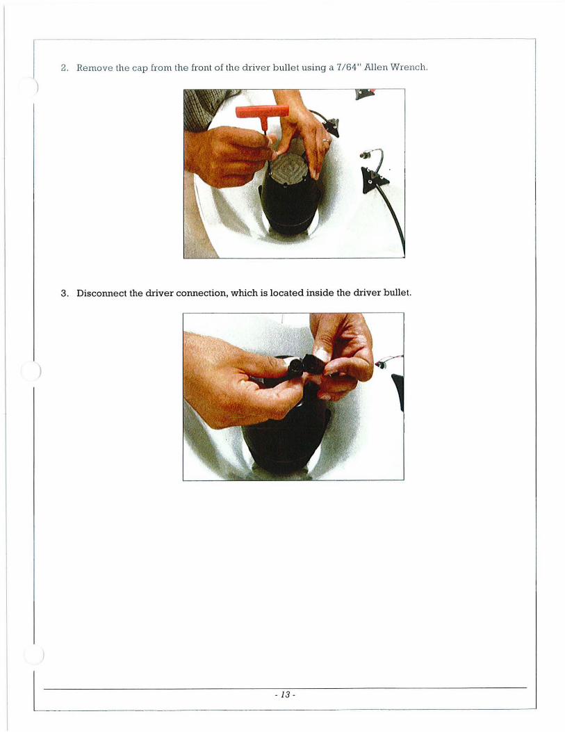
2. Remove the cap from the front of the driver bulle t using a 7/64" Allen Wrench.
)
3. Disconnect the driver connection, which is located inside the driver bullet.
L- ---- -- 13 -

4 . With the drivers facing up , r emove the four screws from the b ack of the driver using a 5/32" Allen Wre nch, and lift the driver out of the unit.
5. Install r eplacement drive r, re connect drive r cable, replace driver bulle t cap, and replace front g rille.
Total estimate d repair time: 25 minutes.
Problem: Faulty amplifier- excessive noise, fault light, clipping light permanently illuminated, insufficient output .
Description: A faulty amplifie r can develop various symptoms. An amplifier troubleshooting guide is available from ATC.
To replace a faulty amplifier, perform the following steps.
1. Ensure the Amplifier Pack is powered down and all connectors are disconnected.
2. Remove the 6 screws around the top plate of the Amplifier Pack.
- 14 -

I )
)
3. Lift the top plate out of the case and lay it face down on a work surface.
4. Disconnect all cables from the faulty amplifier and remove the four screws holding the amplifier module into position.
5. Mount replacement amplifier module on electronics plate and reapply all connections.
6. Replace e lectronics plate in case.
Total estima ted repair time: 26 minutes.
Spare Parts/Support The following spare parts are available from ATC for field or depot level repairs and replacements.
- 15-
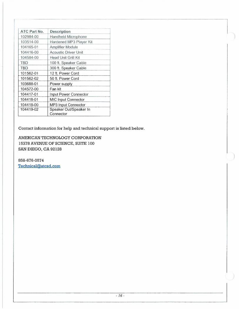
ATC Part No . Descrip tion 102984-00 Handheld Microphone 103514-00 Hardened MP3 Player Kit 104 165-01 Amplifier Module
10441 6-00 Acoustic Driver Unit 104584-00 Head Unit Grill Kit TBD 100 ft . Speaker Cable
TBD 300 ft. Speaker Cable 101562-01 12 ft. Power Cord 101562-02 50 ft. Power Cord
103688-01 Power supply 104572-00 Fan kit 104417-01 Input Power Connector
104418-01 MIC Input Connector
104418-00 MP3 Input Connector 104419-02 Speaker Out/Speaker In
Connector
Contact information for help and technical support is listed below.
AMERICAN TECHNOLOGY CORPORATION 15378 AVENUE OF SCIENCE, SUITE 100
SAN DIEGO, CA 92128
858-676-0574 Technical@atcsd. com
----------------------------------------J-6------------------------------------- I -~
)

~--
Specifications LRAD-1 OOOX Technical Specifications
Emitte r Weight 85 lbs (without accessories)
Emitter Dimensions See Figure l (Page 2)
Emitter Construction Molded Low Smoke Composite
Electronics Module Dimension 2 1.2" X 16" X 8.3"
Electronics Housing Watertight Molded Case
Maximum SPL 152 dB @ l Meter
Power Consumption Normal Powe r Consumption 300 Watts
Peak Powe r Consumption 900 Watts
Acoustic "Beam" Width +/ - 15°@ 1kHz -3dB
Safety MIL-STD-14 7 4D
Ele ctromagnetic Compatibility FCC Class A radiated and conducted emissions
Environmental
Random Vibration MIL-STD-810F, Method 514-4, Wheeled Ve hicles
Shipboard Vibration MIL-STD-167 -lA
Shipboard Shock MIL-S-9 100, Class I, Shockgrade B
SRS Shock MIL-STD-810F, Method 516.5, Proce dure 1 (Functional Shock)
High/Low Te mp Oper a tional MIL-STD-810F, Method 501.4 & 502.4, Procedure 2, -33° to 71 o C
Rain MIL-STD-810F, Me thod 506.4 , Procedure 2, Blowing Rain
Opera ting Humidity MIL-STD-810F, Me thod 507.4
Salt Fog MIL-STD-810F, Method 509.4
- 17-

J


Merlin Detect & Deter Encana Middle Fork Pond
System Overview
1 September 2009 Detect, Inc.
The Merlin system primarily consists of a 30-kW, horizontal-scanning, marine radar connected to three computers. The radar interface computer (RIC) captures the radar data into a computerized format. The Merlin Processor Computer analyzes the data in real-time to detect birds and initiates sound files if birds are detected within the guard zone over the Middle Fork pond. Finally, a Merlin Remote Display Computer is located in the Completions Bull Pen at the Main Office to observe the system. Additional components include a computer keyboard, video monitor, and mouse (KVM), a network switch to network the two computers, and battery backup power (UPS). The components in the radar cabinet are described first.
UPS
Turn on the UPS. Allow it to self check and stabilize.
All of the computer and radar components in the radar cabinet are powered through the UPS. Brown outs or short duration black outs will not directly affect the system operation. The air conditioner is not operated on backup power.
Additionally, the AC is run on a different electrical circuit than the radar and computers to eliminate the chance of spikes caused by the compressor cycle.
Also a 5 (five) minute Shut-down controller is installed. If power is lost for 5 minutes the controller shuts down the UPS so that the system is completely powered down.
KVM
The KVM console allows one keyboard, video monitor and mouse to be shared between the two computers. Select the 1 button to view the Radar Interface Computer- A. Select the 2 button to view the Merlin Processor Computer- C. Only switch 1 and 2 are used on this 8-port switch.
When the KVM starts for the first time it requires a password to begin operating. The user name is 00000000 and the password is 00000000 (by default). On occasion the number lock is engaged on start up. If you cannot get the zeros to enter on the screen, then press the Fn (function) button and then tap the zero button.
Radar
1. The radar is controlled by software on the A computer. Only 1 check box is used in the software interface called Sharpeye controller. This is one of two check boxes toward the bottom. One is a box for "High Power" and the other is titled "Run"
2. Check that the 220V transformer is switched "ON" and that the radar processor key is in the "ON" position. These units are located to the right hand side of the cabinet facing the pond. The transformer sits on a shelf at the top and the radar processor sits below it.
1

3. The Sharpeye software should open automatically. After making sure that the transformer and radar processor are on and that the radar antenna is clear of obstructions, check the box "Run". Leave the High Power box unchecked.
4. The antenna will begin rotating.
5. To shut down the radar
• Uncheck the "Run" button to return the radar to Standby Mode • The antenna will stop rotating • Turn the key switch on the radar processor to "OFF" and switch the transformer
to "OFF" to completely power down radar
Radar Interface Computer -A
The Radar Interface Computer (RIC) is connected to the radar by a signal cable. This computer acquires the radar data and formats them for processing by the Merlin software. This computer is also labeled with its network name A (10.228.19.90). This computer starts automatically when the UPS is powered on.
Select the A computer on the KVM switch. The SeaScan Server program will start automatically. It can also be started by double-clicking its icon on the desktop. The SeaScan Server program simply has to be running. It requires no other controls.
Merlin Processor Computer
The Merlin Processor Computer- C runs 2 programs. The Merlin Server program processes the radar data acquired by the RIC to detect birds. The Merlin Haze program monitors those birds and if they are observed flying over the guard zone a sound file is played in response.
Switch the KVM to 2 to view the C computer. Wait for Windows to boot up completely.
The Merlin Server program should appear automatically; if it does not simply start the program by double-clicking its icon on the desktop. Once opened, notice the 4 dot icons across the top of the Merlin Server window. There must be 4 green dots before the Merlin Data Server can be started. If one or more are red, this indicates a problem, which must be corrected before continuing. For instance, if the "RCI" and "Radar" dots are red, then the SeaScan Server may not be started on the A computer, so no radar data are available for processing.
When the Merlin Server program is started and shows 4 green dots, click File- Start to start the program. After a moment the status lines in the Merlin Server table change from red to yellow, turn On, and begin displaying much useful, though cryptic information. The Merlin Server does all the hard work of processing the radar data. The Merlin Server is not very exciting to watch.
To stop Merlin Server, click File- Stop. To shut it down, click File- End.
2

)
)
3

I
4

The Merlin Server program uses much of the computer's resources. As such it may make the computer slow to respond to commands (mouse clicks). Allow a bit of patience on the C computer when the Merlin Server is running.
The Merlin Haze program plots the bird locations in relation to the guard zone and initiates the sound response as needed. The program should load automatically but if it does not the start the Merlin Haze program by double-clicking the icon on the desktop. As long as the Merlin Server program is running properly, the Merlin Haze program simply has to be opened to function properly. If Merlin Server is not operational "Radar Offline" will show in the center of the screen.
The Merlin Display program is not required to be running at the radar cabinet, but it may be started to view the bird tracks in a more user friendly display than is given by Merlin Haze. Merlin Display can be started by double-clicking its icon on the desktop. The Merlin Display shows the bird tracks overlaid on an aerial photo of the site and includes a depiction of the guard zone. Merlin Display will only function if Merlin Processor is operating properly. If Merlin Server is not operational "Radar Offline" will show in the center of the screen. The Merlin Display is also run on the Remote Display Computer in the Completions Bull Pen.
LRAD Amplifier
The LRAD's amplifier is inside the cabinet on the left hand side. It has a breaker and On/Off switch on the face. To stop sounds from playing when working in and around the Radar simply switch the amplifier to OFF. Turn the amplifier back ON when ready to resume deterrent sounds.
LRAD Sound Controller
The LRAD sound controller is located below the LRAD amplifier. It contains an Acromag which is a digital switching device and a solid state mp3 player. The Acromag controls and monitors the mp3 player containing the sound files used for hazing. Each device has its own power supply and they are plugged into the UPS. The sound files are stored on a removable compact flash card. Please check with DeTect staff before altering any of the sound files on the media card as unauthorized sounds may damage the LRAD speakers. These components should not require servicing, however if sounds are not being played they may need to be power cycled to reset the devices.
Remote Display Computer
The Remote Display Computer in the Completions Bull Pen is connected to the computers in the radar cabinet by the Encana network. The Remote Display Computer simply runs the Merlin Display program to display the results of the Merlin Processor overlaid on an aerial photo of the site and with the guard zone depicted.
Green dots will move about on the Merlin Display. These are birds, but may also be deer, elk, moving trees, people, or vehicles. Some tracks are long and clear and leave a trail to show their direction and speed. Some tracks are short and may appear to pop on screen and disappear.
Bird tracks within the guard zone will initiate the sounds but there is currently no indication of this in the Completions Bull Pen. The remote display is for observation purposes only.
5

If "Radar Offline" is indicated in the center of the screen, then something is amiss. Perhaps the radar has stopped, perhaps the Radar Interface Computer, the Merlin Processor Computer, or one of their software components has stopped. Perhaps the electricity has gone out at the radar pad. Perhaps the air conditioner has stopped and allowed the system's temperature to get too warm. In any case, contact Tom Coburn or Kevin McDowell if Radar Offline is on the display.
Logging On
The Merlin computers automatically log on when started. If a logon is ever required:
User Name: Merlin Password: MF Bird1
Both radar computers use the same username and password.
6

Checklist for System Startup
1. Turn on the UPS.
2. Enter username and password for KVM (eight zeros for each). Select 1 on the KVM switch to select the A computer with radar software.
3. Power up radar by switching the 220V transformer on and the turning the radar processor key on.
4. Click the "Run" check box on the Sharpeye software (Leave High Power unchecked). The antenna will start spinning.
5. Assure the SeaScan Server program automatically started on the A computer.
6. On the C-computer open the Merlin Server and assure 4 green dots.
7. Click File- Start and watch until the server table shows all functions on (except Data Server line will show "off' and "untested").
8. Open the Merlin Haze program by double-clicking it icon on the desktop if it did not start automatically.
Checklist for Normal Shutdown
1. Stop and Close the Merlin Haze and Merlin Server program on the C computer. Close all other programs and turn the C computer off.
2. Stop SeaScan software on A computer. Uncheck "RUN" on the Sharpeye Radar controller. Close any other software, and turn A computer off.
3. Turn off the 220V transformer and turn the key to "OFF" on the radar processor.
4. Turn off UPS.
7

Remote Display Computer In Completions Bull Pen
1. Turn computer on. Use your Encana credentials to access the programs.
2. If the Merlin Display program is closed, open it by double-clicking its icon on the desktop.
3. Birds can be observed as green dots tracking across the map.
4. Birds tracking across the guard zone will initiate the sounds to play in the field, but no noise is made on the Remote Display Computer.
5. If the "Radar Offline" message is observed in the center of the screen, this indicates that radar data are not available because the network is down, one of the two computers at the radar pad are down, the radar is down, or some other problem has occurred.
Contact Tom Cogburn or Kevin McDowell to begin trouble-shooting.
6. If the Display does not appear to be functioning, you may close and re-open the Merlin Display program or restart the computer.
7. The Remote Display Computer is intended as a check that the system is functioning properly.
Logging On
The Merlin computers automatically log on when started. If a logon is ever required:
User Name: Merlin Password: MF _Bird1
Both radar computers use the same username and password.
8

Trouble-Shooting Checks
If the system is not functioning properly, note the following. Information moves through the system in the following way. If one link is broken later parts cannot function.
1. The Air Conditioner is on a separate circuit from the radar and computer components, but if it is not cooling properly, the system will shut itself down to protect from overheating. The multiple electronic components inside the cabinet create a lot of heat. If the AC is not cooling properly, the system will overheat and shut down.
a. Perhaps the AC filter requires cleaning.
2. The radar motor is powered by a 220V step up transformer. Ensure that the transformer is plugged in and that the breaker is in the ON position. Also check that the Radar Processor (black box) is powered (green light illuminated) and the key is switched to the ON position.
3. The UPS is the first component in the system (aside from the radar's power supply and the separately powered AC).
a. If the UPS is off, no other components will have power. b. The UPS may have turned off due to an extended power outage. c. The UPS may have turned off due to excessive heat in the cabinet as noted
above.
4. The Radar Interface Computer is next in the system. a. Is the A computer on? b. Is the antenna spinning? c. Is the Sharpeye radar screen updating numbers? d. Is the SeaScan Server program running? e. Sometimes restarting either the programs or the computer will reset everything.
5. The Merlin Processor Computer is next in the system. a. Is the C computer on? b. Is the Merlin Server program open and started? c. Are the lines in its table yellow, on, and updating regularly? d. Is the Merlin Haze program on?
6. The Long Range Acoustic Device (LRAD) system is next. a. Does the emitter head have power? b. Are all audio lines connected? c. The Merlin Haze program shows a little Speaker icon when a sound is being
played. d. Power cycle the Amp, LRAD controller, and mp3 player.
7. The Remote Display Computer is last in the system. a. If the Remote Display Computer and its Merlin Display software are functioning
properly and if the entire system in the radar cabinet is functioning properly, but the Remote Display Computer continues to show "Radar Offline", then perhaps the Network Connection is at fault?
8. Always check AC, UPS, A computer, C computer, LRAD, Network Connection, and Remote Display Computer in that order.
9

9. If nothing can be determined to be faulty, a complete or part ial shu t down and start up sometime clears a fault.
Simplified Order of Operations
a. A computer 1. Sharpeye Radar Controller 2. SeaScan Server program
b. C computer 1. Merlin Server program 2. Merlin Haze program
Contact DeTect, Inc. for Tech Support at 850-763-7200 during regular business hours.
After hours call 850-774-7334
Email questions to [email protected] and [email protected]
Maintenance
1. The A/C filters should be cleaned monthly. 2. The computers should be restarted once per month. 3. Every three months the radar scanner tower should be operated.
a. Power off the antenna b. Clean the telescoping legs of sand and grit c. Unbuckle the three turn buckles on the stand d. Apply a dry graphite lube to the legs e. Use the key to run the legs down and then back up.
i. There is a limit switch in the screw motor to stop movement in both directions
f. Tigh ten the buckles back when fully raised g. Retu rn power to the radar antenna
)
10

J