Galv Lit Review
38
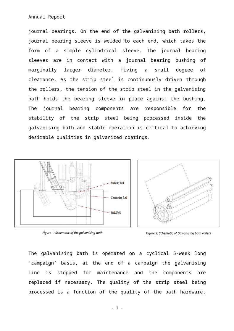
[Type text] Literature review Introduction to the Industrial problem Galvanising is a coating application performed to give a Fe substrate protection from oxidation in a surrounding atmosphere. Protection is achieved by two methods; by the corrosion resistant Zn coating layer itself and also by the Zn acting as a sacrificial anode [1]. Galvanizing is applied to a steel strip substrate inside a hot dip galvanising bath, where steel strip is continuously processed, Zn bonds to the strip steel as it is continuously driven through the bath. The strip steel is held in place a series of rollers which guide the strip through the bath and into a set of gas knives where the thickness of the coating is controlled. In order for a Zn coating to be successfully applied with the correct thickness and minimal surface defects, the stability and operation of galvanising bath hardware is essential. A schematic of the three main rollers in a typical design of a galvanising bath is shown in figures 2, with the rollers respective geometry and dimensions relative to the galvanising bath shown in figure 1. The rollers are manufactured from stainless steel grade 316l, with a coating of W-Co applied via ‘high velocity oxy-fuel’ or HVOF spray. The rollers are held in place while being able to freely rotate radially by a system of
-
Upload
rhys-faulkner -
Category
Documents
-
view
236 -
download
4
description
Literature of Materials suitable for a galvanising bath
Transcript of Galv Lit Review
[Type text]
Literature review
Introduction to the Industrial problem
Galvanising is a coating application performed to give a Fe substrate protection from
oxidation in a surrounding atmosphere. Protection is achieved by two methods; by the
corrosion resistant Zn coating layer itself and also by the Zn acting as a sacrificial anode [1].
Galvanizing is applied to a steel strip substrate inside a hot dip galvanising bath, where steel
strip is continuously processed, Zn bonds to the strip steel as it is continuously driven through
the bath. The strip steel is held in place a series of rollers which guide the strip through the
bath and into a set of gas knives where the thickness of the coating is controlled. In order for
a Zn coating to be successfully applied with the correct thickness and minimal surface
defects, the stability and operation of galvanising bath hardware is essential.
A schematic of the three main rollers in a typical design of a galvanising bath is shown in
figures 2, with the rollers respective geometry and dimensions relative to the galvanising bath
shown in figure 1. The rollers are manufactured from stainless steel grade 316l, with a
coating of W-Co applied via ‘high velocity oxy-fuel’ or HVOF spray. The rollers are held in
place while being able to freely rotate radially by a system of journal bearings. On the end of
the galvanising bath rollers, journal bearing sleeve is welded to each end, which takes the
form of a simple cylindrical sleeve. The journal bearing sleeves are in contact with a journal
bearing bushing of marginally larger diameter, fiving a small degree of clearance. As the strip
steel is continuously driven through the rollers, the tension of the strip steel in the galvanising
bath holds the bearing sleeve in place against the bushing. The journal bearing components
are responsible for the stability of the strip steel being processed inside the galvanising bath
and stable operation is critical to achieving desirable qualities in galvanized coatings.
Annual Report
Figure 1: Schematic of the galvanising bath Figure 2: Schematic of Galvanising bath rollers
The galvanising bath is operated on a cyclical 5-week long ‘campaign’ basis, at the end of a
campaign the galvanising line is stopped for maintenance and the components are replaced if
necessary. The quality of the strip steel being processed is a function of the quality of the bath
hardware, as the duration of a campaign increase, the bearing components deteriorate and the
quality of the strip decreases. In the first week of galvanizing, typically the best quality
galvanized steel is produced, which is a full-finish automotive grade galvanized strip steel.
The ability to produced full finish grade galvanized strip steel represents a huge financial
incentive for Tata steel, due to the increased revenue from sale prices, therefore a potential
increase in the volume of full finish grade galvanised steel produced through the application
of improved bearing performance is the topic of interest in this engineering doctorate.
Further financial incentives in addition to greater volumes of higher quality galvanised strip
steel include the ‘lost production time from maintenance, inflated maintenance costs, bearing
replacement expenditure, a higher tonnage of defective coils and unnecessary zinc
overcoating’ [2] due to instability of the strip steel being processed. Therefore the application
of bearing components with greater wear resistance and subsequent increased operational
stability has a significant impact on the financial sustainability of the galvanizing line.
Currently the bearings are cast from Co-Cr based allows such as Stellite and Wallex, however
an emerging technology in Laser Cladding has the potential to clad a cylindrical journal
bearing components with more wear resistant materials, allowing greater volumes of full
finish galvanized steel to be produced. In order to understand the fundamental mechanisms of
bearing wear and failure, a study of the tribological processes has been undertaken in the
following section.
- 1 -
Annual Report
Tribology (Wear), Bearing Design and operating conditions
In engineering terminology a bearing can be defined as follows: ‘The word bearing, applied
to a machine or structure, refers to contacting surfaces through which a load is transmitted”
[3]. In a bearing system which is also responsible for facilitating relative motion between one
or both surfaces, it is necessary to minimise the friction which will account for reduced wear
of the contacting surfaces of the bearing components. A substance which is interposed
between two contacting surfaces in order to minimise friction and subsequent wear of the
contacting surfaces is termed a lubricant. Bearings can be characterised into many types,
depending on their nature of operation. Sliding or journal bearings utilise a sole sliding
member which rotates or translates against a support, known as a ‘bushing’. A roller bearing
is another type of bearing which has additional balls or rollers located between the two
sliding surfaces which further reduce wear and friction.
The galvanising bath contains a system of large roller which allow the strip steel to pass
through the galvanising bath, shown in figures 1 and 2. The largest roll is the sink roll which
sits at the bottom of the galvanising bath and is the most substantial to the quality of the
galvanised steel. The correcting and stabiliser roll maintain the positional stability of the
galvanised strip steel as it exits the galvanising bath. Each roll is held in place with a journal
bearing system, consisting of a sleeve and bushing component and theoretically designed to
operate with a thin film of lubrication occurring in between the two components. Larger
bearing components on the larger sink roll, with journal bearing components being thicker
with greater internal and external radii. The correcting and stabiliser rolls and bearing
components are of the same dimensions, with smaller journal sleeve and bushing components
being interchangeable between the correcting and stabiliser rolls.
The process of wear, which can be characterised as the loss of material, which in a general
approach can be characterised into 3 distinct mechanisms. The physical removal of material
from a solid surface can only by; melting of material, chemical dissolution of material or by
the physical separation of bonded elements through mechanical interaction [3]. The physical
separation of material occurs through mechanical forces, typically due to a single application
- 2 -
Annual Report
of high straining load or through the cyclic loading at lower loading magnitudes. Wear is
often the result of a combination of processes, such as mechanical interactions through
abrasion coupled with chemical dissolution in a corrosive medium.
It is highly desirable to minimise bearing wear in all applications of bearing usage, to prolong
the service life of bearing components. In the case of the galvanising bath, since all pot
hardware is exposed to molten Zn with variable quantities of Al depending on the type of
galvanising bath to minimise intermetallic layer formation during the Fe-Zn bonding between
the substrate and galvanised layer; all exposed surfaces in the galvanising bath are subject to
material dissolution when in contact with molten Zn and suspended Al elements. Dissolution
is one mechanisms in which material is removed from galvanising bath hardware with
material lost through mechanical interaction constituting a second mechanisms of material
loss of galvanising bath hardware. The method of material removal through mechanical
interaction can be subdivided into further wear mechanisms characterised by the method of
surface damage.
The accumulation of damage to a surface, such as progressive accumulation of material loss
through ‘tribological contacts’ or ‘tribocontacts’, a term used to describe the interactions of
two or more contacting surfaces in the field of tribology, the science of surface interactions
when at least once surface is in relative motion [3]. In the context of tribocontact’s, surface
damage refers to a topographical or microstructural change, or both conjunctively, on a
surface or subsurface layer of material in a solid body [3]. Tribological topography, or
‘Tribography’ can be classified as the topographical or structural changes made to a material
as the resulting action of tribocontact’s. In order to generate a deeper understanding of
surface damage of galvanising bath hardware, it is imperative to relate the mechanisms of
surface damage to the geometry in question, material properties and other tribological
interactions to the overall system of wear, known as the Tribological system, or ‘tribosystem’.
Surface damage of an engineering component can be classified by the surface damage
present. It is possible for a tribological surface, or ‘tribosurface’ to experience a sole
mechanism of damage and subsequent loss or gain of material, but in reality it is more typical
for several mechanisms of surface damage to occur simultaneously, with several mechanisms
occurring conjunctively or independently of each other at the same time. In the case of the
galvanising bath, a minimum of two mechanisms are present when submerged in the
galvanising bath, which includes material loss through mechanical interaction of the rotating
- 3 -

Annual Report
journal sleeve surface against the bushing and also material loss through dissolution inside a
corrosive medium.
All submerged components in the molten Zn bath are subjected to dissolution in the molten
Zn and Al, but only the tribosurface’s of the journal bearing bushing and sleeve are subject to
further wear mechanism’s through mechanical interaction, such as abrasive, polishing and
fatigue wear. The tribosurface’s of the journal bearing components refers specifically to
external radii of the journal sleeve component, which is in contact with the internal radii of
the bushing component, the relative motion between these two contacting surfaces is
essentially for the classification of a them being tribosurface’s.
Surface damage can be categorised as follows [3]:
1. Structural changes, in which damage accumulated through processes aging,
tempering, phase transformation and recrystallization. It is possible that this form of
damage to a structure will occur free from external influence. This category of
damage to a material relies on the assumption of a deviation from the desired or
reference set of material properties, however in some cases internal structural changes
may be beneficial to the engineering component in question, such as an increase in
yield strength through an aging or tempering process. Regarding the journal bearing
components which are currently cast components of CoCr; when submerged in a
galvanising bath this mechanism of surface damage occurs when Co reacts with Al
inside the galvanising bath to form very hard Co-Aluminide intermetallic particulates.
[4-5]
2. Plastic deformation, either locally or extensively, is the residual or permanent change
in shape of a material through a mechanical strain occurring in a state of stresses
beyond the yielding stress, resulting in irreversible and permanent net change in the
geometry of the component. Localised plastic deformation has been observed on
journal bearing components in the galvanising baths in the form of deep grooves cut
into the surface, hypothesised to be the result of a three-body tribosystem of wear. [5]
3. Surface cracking, a resulting mechanism of localised plastic deformation under cyclic
loading, from either thermal or mechanical loading. The nature of cracking differs
- 4 -
Annual Report
between both thermal and cyclic loading, with mechanical loading typically forming a
series of parallel cracks while thermal loading generate a lattice network of cracks. [5]
In addition to the mechanisms of surface damage listed previously, surface damage which
explicitly involves the loss of material from a tribosurface is termed ‘wear’. The volume of
material lost from a surface is known as a ‘wear scar’, which can take the form of various
shapes and sizes depending on the mechanism of material removal. Wear can be categorised
into mechanical and chemical mechanisms.
Abrasive wear can be defined as the progressive loss of material due to relative motion
between two or more contacting tribosurfaces, and can be defined as ‘hard particles or hard
protuberances that are forced against and move along a solid surface’ [3]. Whereas the
bearing system currently used in the galvanising bath would ideally operate with two body
system of wear, with two contacting faces of a journal bearing components, the tribosystem
that develops in reality in between the tribosurfaces of the bearing components is three body
or greater system of wear. The introduction of hard intermetallic particles and other wear
debris is accountable for creating comparatively deep wear scars in the bearing bushing
surfaces upon removal from the bath.
When abrasive wear occurs between two contacting surfaces, material loss will occur on both
surfaces, however material loss will be more severe if one surface is softer than the other.
Engineering components subjected to abrasive wear are often deliberately manufactured to
have a hard surface in contact with a softer surface, so that the softer surface will wear
preferentially to the harder surface.
The rate at which a surface abrades is dependent on several factors, including the geometry of
the surfaces and the contacting areas, the speed of the relative motion between the two
surface, and the introduction of separate bodies which translate the two body wear system
into a three body wearing system. Therefore, the total loss of material from a component is
not solely due to the material properties of that component, instead a range of external
influence can accelerate abrasive wear.
In practise it is common for several surface damage mechanism to occur in combination and
accelerate the effect of surface damage. The surface damage mechanisms may be activated
though different wear mechanisms while still acting conjunctively in the net loss of material
from the bearing component. The formation of hard intermetallic Co aluminides on the
- 5 -
Annual Report
surface has been noted in several studies which investigated the application of Co-Cr Stellite
bearings inside the galvanising bath. These studies [4-5] found that Co-Aluminides form on
the surface of Stellite components immediately when submerged inside the galvanising bath.
While the formation of such Co-Al particles is inherently a chemical process, they are often
attributed to severly accelerating bearing bushing wear and failure when they become
entrapped inside the bearing bushing and sleeve components, highlighting the ability of
separate wear mechanisms to accelerate wear in combination.
Operating conditions of Galvanising Bath bearing components
The fundamental wear mechanisms present in the galvanising bath are not independently
responsible for the failure of galvanising bath materials; wear can be accelerated by the
nature of the operating conditions applied to the bearing components. A study identified 5
different failure mode of galvanizing line journal bearing components which include rapid
and excessive bearing wear, flutter of the strip steel be processed, bearing vibration, bearing
skidding and sticking and bearing lock up [2]. The failure modes listed are phenomena of
which some act independently of material properties, instead they are generated by the nature
of the geometry and assembly of the galvanising bath hardware as well as the applied loading
conditions. The bearing failure mechanisms listed show how mechanical loading and
operating conditions can accelerate the effect of tribological interactions between the bearing
components.
The study [2] states that the most common mode of failure of the galvanising bearings is
‘rapid and excessive’ [2] wear of bearing components. The contributing factor to this mode is
listed as material corrosion, high surface friction and low wear resistance of the bearing
components. In this mode of bearing failure would be classified as a significant quantity of
material loss such that the bearing component can sufficiently operate as it was intended.
Excessive bearing wear is also attributable to the presence of high friction in journal bearings,
which generates friction forces of significant magnitude and increases likelihood of
development of plastic straining which accounts for material removal. Journal bearings
should theoretically operate with a thin film of hydrodynamic lubrication, which would
generate at a high enough bearing rotational speed depending on other factors such as the
molten Zn viscosity and coefficient of friction. If a thin boundary layer film of lubrication
- 6 -
Annual Report
was present and the bearing was operating hydro-dynamically then the friction forces and
corresponding abrasive wear material loss would reduce. However, due to the rotational
speed inside the bearing journal and sleeve components, sufficient lubrication is not present
and the bearings operate within the ‘boundary lubrication’ region, which has minimum
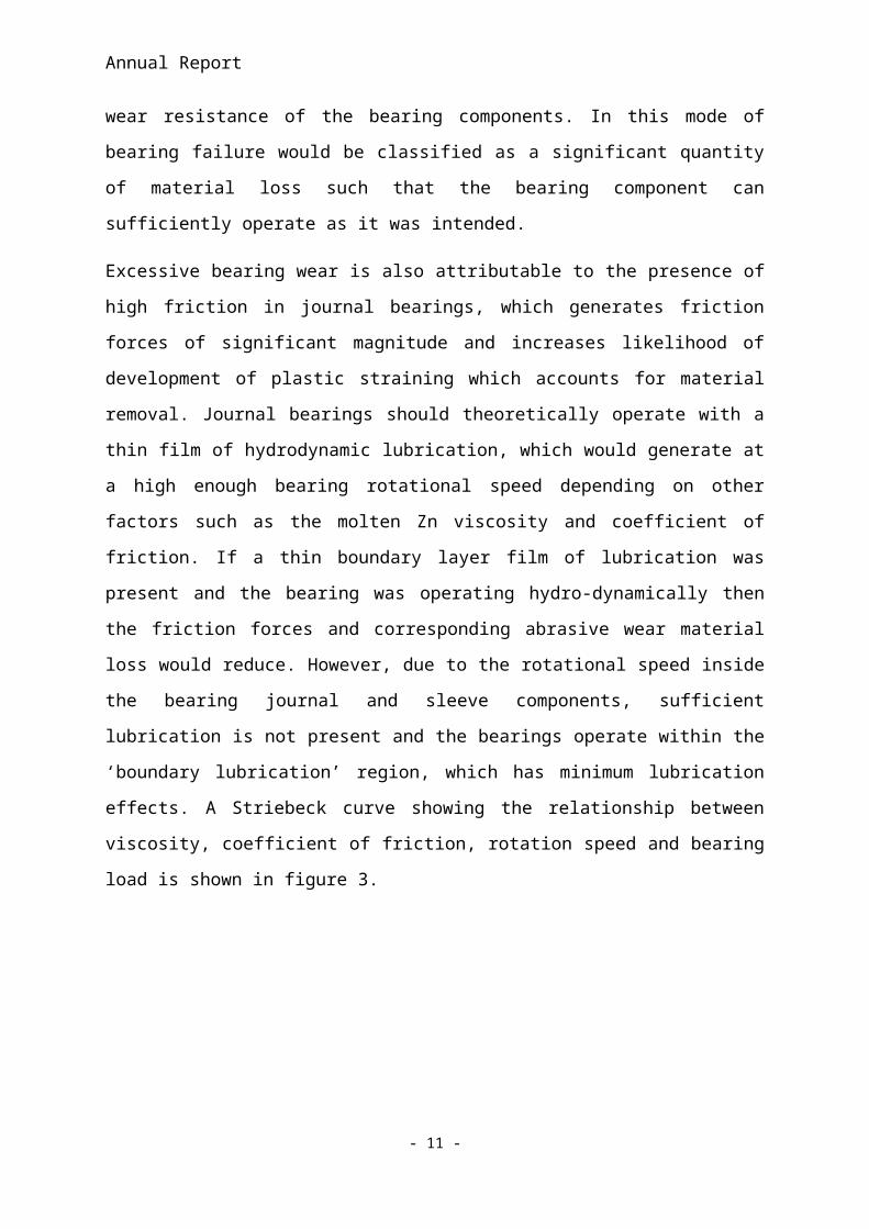
lubrication effects. A Striebeck curve showing the relationship between viscosity, coefficient
of friction, rotation speed and bearing load is shown in figure 3.
Figure 3: Striebeck curve [2]
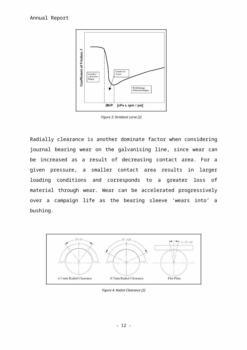
Radially clearance is another dominate factor when considering journal bearing wear on the
galvanising line, since wear can be increased as a result of decreasing contact area. For a
given pressure, a smaller contact area results in larger loading conditions and corresponds to
a greater loss of material through wear. Wear can be accelerated progressively over a
campaign life as the bearing sleeve ‘wears into’ a bushing.
Figure 4: Radial Clearance [2]
- 7 -
Annual Report
The study [2] cites the second most common mechanisms of bearing failure as bearing
vibration and excessive sheet flutter, as a mechanisms for accelerating bearing wear.
Intriguingly this second most common method of bearing failure is due to mechanical
interaction of galvanising bath hardware with the strip steel being processed, and is not
directly a Tribological process effecting the journal bearing components. When the strip steel
sheet flutters upon exiting the galvanising bath; such sheet flutter can be translated into
violent oscillations in the bearing journal sleeves. Excessive oscillations at the start of a
galvanising bath campaign are the result larger radial clearance in the bearing components
and often become less severe throughout the course of a campaign as the bearing sleeve
‘beds-in’ to the bushing and radial clearances reduce. Violent oscillations in bearing
components are still present throughout the campaign, with one theory identifying a rapid
change in strip gauge or thickness being responsible along with a rapid and significant change
in bearing load being attributable to violent oscillations throughout the campaign life.
Bearing skidding, where the journal sleeve no longer freely rotates against the bearing
bushing and physically ‘skids’ can have severely adverse effects on both strip quality and
wear of the journal bearing components. This mechanisms is inherently linked to radial
clearance, with the study suggesting the radial clearances may reduce over the course of a
campaign due to dross build up, causing sudden seizures in free rotation. Material selection is
suggested as a viable solution, with materials selected on the basis of Zn and Al dissolution
characteristics.
Following an assessment into the tribological processing and operating conditions, another
study has been was considered which assessed the nature of the stresses in an ideal loading
scenario. The study calculated operating stresses of bearing component for comparison
against the yielding criteria was carried out utilising laboratory testing and finite element
analysis simulation [5]. Currently, materials properties and performance of bearing
components inside the galvanising bath are well defined, but the analysis of operating stresses
and strains which the bearings are subjected to is not clearly defined or understood. The study
aimed to clearly define the operating stresses of bearing components through FEA
simulation, with input parameters assumed from actual loading information gathered from a
galvanising line, such as tension information of the strip steel.
- 8 -
Annual Report
The study [5] used bearings of two sizes, a smaller bearing used in laboratory testing, with a
diameter of 76.2mm and a length of 50.8mm, and a larger bearing, of diameter 180mm and
175mm length, which corresponds to a full size bearing used in a continuous galvanising
bath. It was assumed that plain strain was the only method of plastic deformation and a Von
Mises Stress criteria was applied in order to establish the contact area and associated plastic
deformation. Loads of 6.7 kN and 19.7 kN were respectively applied to the bearing
components of specified smaller and larger bearings dimensions. The Co alloy being tested
was measured to have tensile strength 621 MPa at 4600C. In the study the commercial FEA
package used was ADINA for all calculations.
Table 2: operating stress [5]
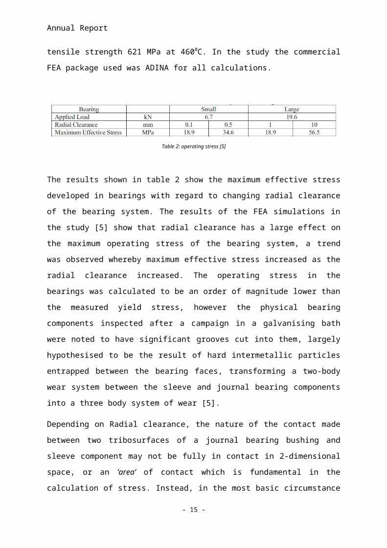
The results shown in table 2 show the maximum effective stress developed in bearings with
regard to changing radial clearance of the bearing system. The results of the FEA simulations
in the study [5] show that radial clearance has a large effect on the maximum operating stress
of the bearing system, a trend was observed whereby maximum effective stress increased as
the radial clearance increased. The operating stress in the bearings was calculated to be an
order of magnitude lower than the measured yield stress, however the physical bearing
components inspected after a campaign in a galvanising bath were noted to have significant
grooves cut into them, largely hypothesised to be the result of hard intermetallic particles
entrapped between the bearing faces, transforming a two-body wear system between the
sleeve and journal bearing components into a three body system of wear [5].
Depending on Radial clearance, the nature of the contact made between two tribosurfaces of
a journal bearing bushing and sleeve component may not be fully in contact in 2-dimensional
space, or an ‘area’ of contact which is fundamental in the calculation of stress. Instead, in the
most basic circumstance where two of circles different radius’ overlap, contact may only
occur in 1-dimensional line space, where contact is made across 1 dimensional line where the
outside radii touch as opposed to a 2-dimesional area of contact. Assuming this occurs then
- 9 -
Annual Report
the stress calculation may not be an accurate representation of the physical contacting stress
occurring in the bearing components.
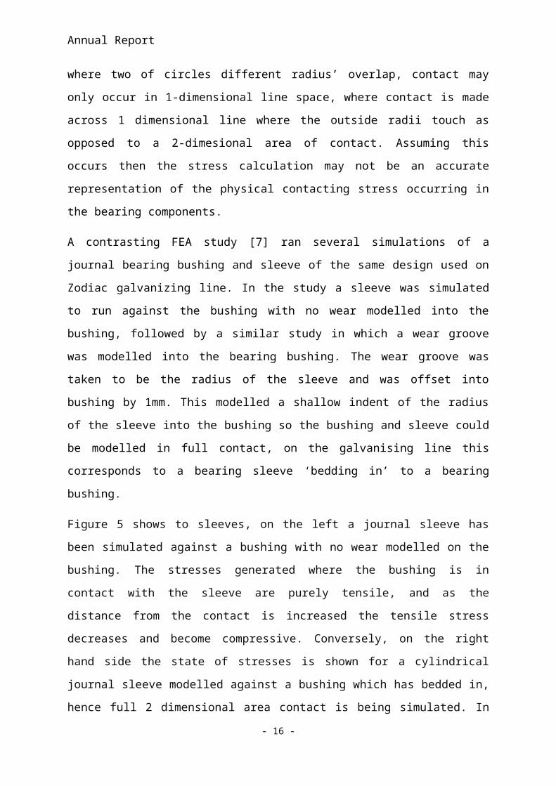
A contrasting FEA study [7] ran several simulations of a journal bearing bushing and sleeve
of the same design used on Zodiac galvanizing line. In the study a sleeve was simulated to
run against the bushing with no wear modelled into the bushing, followed by a similar study
in which a wear groove was modelled into the bearing bushing. The wear groove was taken
to be the radius of the sleeve and was offset into bushing by 1mm. This modelled a shallow
indent of the radius of the sleeve into the bushing so the bushing and sleeve could be
modelled in full contact, on the galvanising line this corresponds to a bearing sleeve ‘bedding
in’ to a bearing bushing.
Figure 5 shows to sleeves, on the left a journal sleeve has been simulated against a bushing
with no wear modelled on the bushing. The stresses generated where the bushing is in contact
with the sleeve are purely tensile, and as the distance from the contact is increased the tensile
stress decreases and become compressive. Conversely, on the right hand side the state of
stresses is shown for a cylindrical journal sleeve modelled against a bushing which has
bedded in, hence full 2 dimensional area contact is being simulated. In this case, the stress in
contact with the bushing is compressive, and is surrounded by tensile stress. Although the
values of stress are similar, the nature of the stress is significantly different between the
sleeves modelled with and without the sleeve being worn into the bushing.
Figure 5: Plastic strain [7]
- 10 -
Annual Report
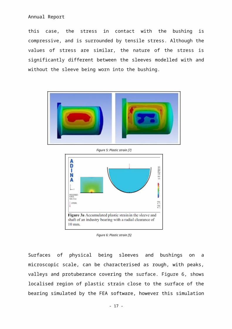
Figure 6: Plastic strain [5]
Surfaces of physical being sleeves and bushings on a microscopic scale, can be characterised
as rough, with peaks, valleys and protuberance covering the surface. Figure 6, shows
localised region of plastic strain close to the surface of the bearing simulated by the FEA
software, however this simulation will not account for microscopic surface roughness and
imperfections which can account for localised yielding in reality, although the simulation
does predict some yielding stress on the surface of the journal bearing component. Another
aspect which the FEA simulation does not account for is the formation of very hard Co-
Aluminides on the bearing surface. Such Co Aluminide intermetallic particulates have been
observed to form almost instantly when submerged in the molten Zn galvanising bath [5], and
whereas the study has simulated an ideal two-body scenario, the reality of physical bearings
inside a galvanising bath operating with entrapped particles inside them may have a
significantly different values of operating stresses.
The FEA simulation proposed in the study provides useful results in predicting hypothetical
state of operating stress in ideal circumstance, but the values of stress are far removed from
reality. In order to account for surface roughness, the study assumed that only 10% of the
hypothetical contact area was actually in contact, due to the microscopic roughness of the
surface. In doing so the study multiplied the calculated values of operating stress by 10,
which generated a value of operating stress of 650MPA, which has surpasses the yield
strength of the Stellite, measured to be 621MPa. The resulting plastic straining is shown in
figure 6.
- 11 -
Annual Report
The study, although arguably limited in the assumption’s made to simulate operating stresses,
highlights the fact that bearings are well defined to meet the requirements of operating
stresses on the galvanising line. Failure of bearing components is therefore not likely a
manifestation of poor engineering design, but more likely attributable to less optimal material
selection and poor preparation for the likelihood of dross build up and entrapped particles
inside bearing systems. With regard to material selection, the following section of this
literature review identifies a promising coating technology with use with galvanising bath
bearings, laser cladding.
Laser Cladding
Laser Cladding is a type of additive manufacturing process whereby layers of material are
built up over a substrate by fusion of a metallic powder via a heat source applied by a laser.
Full fusion bonding is achieved between the clad material and the substrate, and also between
the subsequent layers which are applied progressively to develop the clad coating. A
differentiating factor between laser cladding and other types of Additive Manufacturing
applications is in the definition of ‘Cladding’ which is specifically the bonding of two
dissimilar metals, opposed to a general Additive manufacturing process in which a
component is manufactured using only a single material.
Like many Additive manufacturing processes, Laser Cladding manufactures engineering
components by simultaneous application of metallic powder fused instantaneously upon
contact with a substrate by way of a focused laser beam. The laser applies a very high
temperature localised source of heat capable of melting a metallic powder onto a substrate
surface which solidifies after the laser has perpendicularly travelled relative to the substrate
surface. Repeated applications of solidified layers forms the cladding material on a substrate.
The clad material applied may have significantly different material properties and
characteristics compared to the substrate material, such as a significant increase in hardness
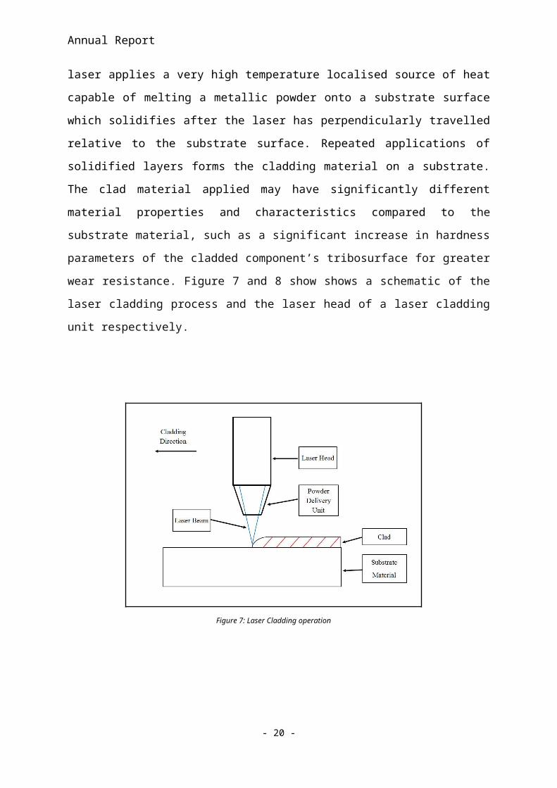
parameters of the cladded component’s tribosurface for greater wear resistance. Figure 7 and
8 show shows a schematic of the laser cladding process and the laser head of a laser cladding
unit respectively.
- 12 -
Annual Report
Figure 7: Laser Cladding operation
Figure 8: Laser Cladding operation [ref]
Laser Cladding’s implication are far reaching and its application has been trialled already in
galvanising bath bearing components. Metallic powders used are primarily alloys based on
Fe, Co and Ni with other common constituent elements including Cr, Mo, and W as well
carbide’s such as W carbide, Cr carbide, Ti carbide, Si carbide, V carbide. Metallic powders
- 13 -
Annual Report
with quantities of carbide powder are often supported in a softer matrix material used to acts
a binder between the carbide powders. Laser clad coatings with high concentrations of
carbide’s are of significant interest for applications inside the galvanising bath.
Laser Cladding is direct competition with several other similar coating technologies, which
are also capable of applying a dissimilar metallic coating to a substrate material. The three
main competing technologies are ‘Plasma Spraying’ and ‘High Velocity Oxy-Fuel’ or HVOF
thermal spraying and ‘Plasma Transferred Arc’ or PTA Welding. Both Plasma spraying and
HVOF are capable of spraying and subsequently coating a larger area compared to laser
cladding, although in the case of Plasma Spraying has disadvantageous in its comparably
weak bonding, chemical inhomogeneity and porosity issues [9].
HVOF thermal spraying is a more successful coating technology compared to Plasma
spraying, however the coatings applied through HVOF still have mechanically weak bonding
compared to the bond formed in laser cladding. Both Plasma spraying and HVOF thermal
spraying do not achieve a full fusion bond between the powdered material and substrate,
unlike laser cladding. PTA welding is capable of achieving full fusion bonding between the
powdered weld material and the substrate, but PTA welding requires a larger heat input,
which subsequently generates a larger heat affected zone, or HAZ compared to laser
cladding. As a result the dilution of PTA welded coatings and the substrate material is larger
than that of laser cladding. Due to larger heat input of PTA welding, distortion of the
substrate material can also occur [9].
Laser Cladding is capable of applying a clad material, with full fusion metallurgical bonding
and due to the localised heat input of the laser, a small HAZ is generated. Dilution between
laser clad material and the substrate material can be relatively small, with ideal dilution levels
optimised to around 5% [9]. Due to localised heat source of the laser, distortion is also
insignificant with laser cladding. A disadvantage of laser cladding with regard to the
competing coating technologies is the slower deposition rate in laser cladding, which means
that laser cladding is arguably a slower coating process [9].
Mechanics of Laser Cladding
- 14 -
Annual Report
The thermodynamics of Additive Manufacturing can be expressed numerically by
modifications of the fundamental heat transfer equations. Three distinct heat transfer
mechanisms of conduction, convection and radiation are present during additive
manufacturing processes including the laser cladding process. All mechanisms of heat
transfer require a temperature gradient between two points of reference for heat to flow,
under the zeroth law of thermodynamics. Conduction is distribution of heat energy between
more energetic particles to surrounding particles with less energy. In solid bodies conduction
occurs due to the internal vibrations of a structure of atoms in a lattice and also by the transfer
of electrons due to the free movement of electrons [10]. Conduction can be described
numerically by equation (1).
Q̇Cond=k t A∆ T∆ x
,∴Q̇Cond=−k t AdTdx
(W ) (1)
Where k t is thermal conductivity, ∆ T is the temperature gradient, ∆ x is the thickness through
which conduction occurs and A is the area normal to the direction of heat transfer. The
equation is known as Fourier’s law, the minus term on the right hand side of equation one
denotes of scenario of heat loss from the system, or decreasing temperature through
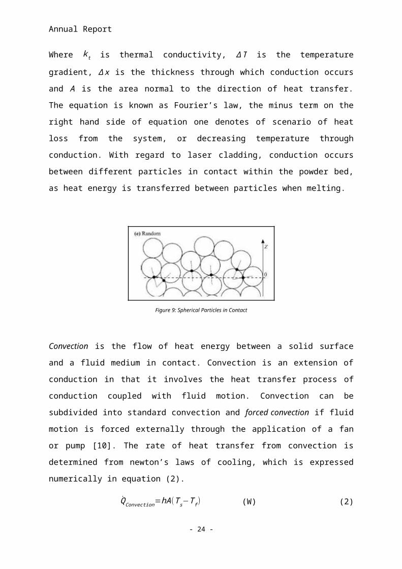
conduction. With regard to laser cladding, conduction occurs between different particles in
contact within the powder bed, as heat energy is transferred between particles when melting.
Figure 9: Spherical Particles in Contact
Convection is the flow of heat energy between a solid surface and a fluid medium in contact.
Convection is an extension of conduction in that it involves the heat transfer process of
conduction coupled with fluid motion. Convection can be subdivided into standard
convection and forced convection if fluid motion is forced externally through the application
- 15 -
Annual Report
of a fan or pump [10]. The rate of heat transfer from convection is determined from newton’s
laws of cooling, which is expressed numerically in equation (2).
Q̇Convection=hA (T s−T f ) (W) (2)
Where h is the heat transfer coefficient, A is the surface area, T s is the surface temperature
and T f is the bulk fluid temperature. Convection occurs in the laser cladding process as
melted alloying particles of the powdered material combine to create a melt pool in a
localised region in contact with the focal point of the laser beam on the surface of the
substrate material. When the material is in the liquid phase before the material re-solidifies,
convection is present in the form of heat flow through the material, which facilitates fluid
motion and diffusion of elements in the melt pool as a crystalline metallic structure is
developed. Natural convection is density driven, as a fluid is heated by a solid body, the
heated fluid experience a decrease in density and will begin to rise above lower temperature
fluid above it with greater density, in these circumstance fluid flow is necessary for the
classification of convection. In addition to natural convection, Maragoni convection is
another mechanisms of convection, in which fluid flow occurs due to the differing surface
tensions of fluid in a melt pool. Both Maragoni and natural convection are present in melt
pools [10].
The third primary mechanism of heat transfer is radiation, in which heat is emitted from a
body in the form of electro-magnetic waves, “as a result of the electronic configurations of
atoms or molecules.”[10]. In both conduction and convection heat transfer mechanism an
intervening medium is needed to facilitate the heat flow; however this is not necessary for
radiation. Thermal radiation refers to the transfer of heat due to a thermal gradient present.
Classic thermodynamic radiation can be described numerically in equation (3), however this
equation requires modification for the radiation emitted by that of a laser [10].
Q̇radiation=εσA (T s4−T surrface
4 ) (W ) , (3)
By combining the heat transfer mechanisms under the first law of thermodynamics, the
conservation of energy principle, and by modifying the equations (1-3) with a unit area and
- 16 -
Annual Report
unit mass, a modified Fourier equation can be used to describe the heat transfer mechanism of
a laser moving over a surface, shown in (4). A schematic of the heat transfer mechanisms is
shown in figure 10.
Figure 10: Mechanics of the melt pool [11]
ρ CP( dTdt
+u∇T )=∇ λ∇T +QRadiation (4)
Equation (4)[11] is a combination of heat transfer presented in equations (1-3), but with
modification to represent a 3-dimensional space by adapting the equation vector form, on a
unit area basis. In equation (4), ρ is a density scalar (x, y, z), u is a velocity vector (Ux, Uy,
Uz), λ is a thermal conductivity vector (Kx, Ky, Kz), Cp is a specific heat capacity constant
pressure scalar, T is temperature vector (x, y, z) and t represents time. The equation can be
used to simulate heat transfer mechanisms applied by a laser generating a melt-pool in 3-
dimensional space.
Galvanising bath Materials
In this section the application of both laser cladding and alternative wear resistant super-
alloys are considered for applications inside the galvanising bath. Stellite 6, a Co-Cr based
Super-alloy with additions of Fe and Mo is the most commonly used galvanising bath
material. Stellite has favourable dissolution and wear resistance inside the galvanising bath,
- 17 -
Annual Report
although recent developments have highlighted several alternative materials with greater
wear and dissolution resistance. A study [6] tested many promising materials, primarily Fe
and Co based, along with laser clad components.
Initial testing of the study focused on Fe based grades of MSA2012 and MSA2020, a super-
alloy with very high concentrations of carbides, which are responsible for increasing
corrosion resistance by having carbide-rich compositions at grain boundaries. In addition to
MSA grades of steels, Tribaloy, a Co-Cr based super alloy was also tested. Tribaloy T400
and T800 have compositions similar to Stellite 6, however unlike Stellite 6, Tribaloy grades
of Co-Cr superalloys have much larger alloying additions of Mo (around 30% of the total
composition), which further inhibit dissolution in the galvanising bath and also decrease the
potential for growth of Co-Al particulates. A disadvantage of Tribaloy is its extremely brittle
nature. Figure 11 and 12 show dissolution rates through material loss per day Tribaloy
grades, both Tribaloy grades show better dissolution resistance compared to Stellite.
Unfortunately the study did not make a direct comparison between MSA grades and Stellite
6, although given Tribaloy marginally better dissolution performance compared to Stellite,
and MSA much greater dissolution than Tribaloy, it is possible the MSA grades 2012 and
2020 may have worse dissolution performance than Stellite 6, with regard to figures 11 and
12, [6].
Figure 11: Dissolution of Tribaloy and Stellite [6]
- 18 -
Annual Report
Figure 12:Dissolution of Tribaloy and MSA [6]
In addition to static dip testing, the study [6] also conducted abrasive wear testing of the
proposed alternative materials. A small scale dry wear testing apparatus was constructed,
consisting of a 35.4mm hemisphere sample mounted against a static seat, with a contact angle
sat at 450. The results of the test are presented in figure 13, in which stainless steel 316L,
Stellite 6, MSA 2012 and a Laser clad WC sleeve was tested against a ceramic bushing. The
test shows that both MSA2012 and the laser clad WC sleeve outperformed the currently used
Stellite 6 bushing, although the laser clad sleeve experienced substantially less wear than both
MSA2012 and Stellite 6 [6].
- 19 -
Annual Report
Table 3:Abasive wear rates of various materials [6]
The results of study [6] show laser cladding as a coating application with significant potential
as a replacement material for Stellite 6 in galvanising baths. Laser Clad coatings for use
inside the galvanising bath at Zodiac have been the subject of several internal reports by Tata
Steel. Initially, static dip testing of laser clad material [12] resulted in a follow up study [13]
of laser clad bearing sleeves being trialled on the testing rig inside the Zodiac plant. The
coated sleeves Tata steel developed were comprised of several layers of different material,
the material’s used consisted of Hastelloy applied exclusively or as a matrix material
supporting carbide powder. Hastelloy is a Ni based alloy with additions of primarily Co, Cr
and Fe. In total a 3.5mm layer coating was applied to a bearing sleeve for testing on the
bearing testing rig.
Hastelloy constitutes the first layer of laser clad applied as a ‘buffer’ layer. The buffer layer
applied in the internal report [13] is intended to suppress residual stresses developed upon
cooling between the layers applied above the buffer layer and substrate material below the
buffer layer. Upon cooling of the buffer layer, a subsequent layers of laser clad material are
applied with additional carbide material set at a percentage of the volume. After a 1mm
buffer layer was applied, a 1mm coating of 70% Hastelloy supporting 30% TiC. A final
1.5mm layer of 40% Hastelloy supporting 60% TiC was applied. In total a 3.5mm laser clad
was applied to a stainless steel 316l bearing sleeve for use on the bearing testing rig, with the
outer surface theoretically having 60% TiC.
The TiC was measured to have a Vickers hardness of 2000Hv, while the Hastelloy matrix
material had a measured Vickers hardness of 500HV [13]. The bearing sleeve is submerged
in 4650C molten Zn, where the bearing sleeve is rotated approximately 63RPM, which is
equivalent to a line speed of 150m/min. A load of 18.63Kn was applied, which the study
claim’s is 50% higher than the line speeds than the loading forces inside the galvanising bath
although contrasting studies have provided alternative calculations of bearing loads which
place bearing load’s at far higher values [7]. The test was conducted for 18 hours in total,
which was not a continuous period of testing. Instead the test in the study was stopped
corresponding to the end of the operator’s shift, at which point the testing rig was shut down
and the zinc solidified. Ideally the laser clad sleeve would have been ground to a smooth
finish of low surface roughness, but grinding of the sleeve was not performed during the test
and the laser clad sleeve was tested with significant roughness on its surface.
- 20 -

Annual Report
Due to the rough surface the laser clad sleeve being tested, the results have no benefit to
supporting a laser clad bearing components application on the galvanising line, however the
report did draw many valuable conclusions. The actual laser cladding process of TiC
highlighted many drawbacks, a homogenous coating of TiC was not achieved due to the
oxidation of the TiC during the cladding process. For this reason TiC was not recommended
for further trials inside Zodiac [13].
Following the unsuccessful trial of TiC [13], a follow up study [14] was proposed of a very
similar laser clad coating but with WC substituted for TiC, a second internal report completed
by Tata Steel on the Zodiac Bearing rig [14]. A 3.5mm laser clad coating was applied to a full
size stainless steel 316l sink roll journal sleeve and tested against a Stellite bushing. The laser
clad coating was split into 3 layers, a initially 1mm Hastelloy buffer layer was applied,
followed by a 1mm layer of 70% Hastelloy and 30% WC, followed by a final 1.5mm layer of
40% Hastelloy and 60% WC. The sleeve was tested against a Stellite bushing at rotational
velocity of 63RPM and a bearing load 18.6Kn inside 4650C molten Zn. The molten Zn
crucible has additions of 0.5%wt Al and <0.01%wt Fe, although Al concentration in the
Zodiac galvanising bath fluctuates between 0.2%wt Al and 0.3%wt Al [14]. The test [14] was
conducted for a period of 17.5 hours, with the testing rig being shut down approximately half
way through, corresponding to a shift ending. In contrast to the first study which trialled a
TiC sleeve with no surface grinding after laser cladding, the WC sleeve was ground to a
surface roughness of 0.2µm Ra, with the Stellite bushing having a surface roughness of
0.71µm Ra.
The testing in the study [14] showed very favourable operating conditions of the laser clad
sleeve against a Stellite bushing. The measured friction coefficients of a benchmark Stellite
sleeve and bushing test was compared to the laser clad sleeve and bushing test, and a
measureable decrease in friction was noted in the case of the laser clad sleeve running against
the Stellite bushing. A polishing effect had occurred, where the roughness of the Stellite
bushing surface decreased from 0.71µm Ra before the test to 0.36µm after testing of the
journal bearing was complete. In addition, the roughness of the laser clad sleeve surface
increased marginally from 0.2µm Ra before the test to 0.28µm Ra after the testing. A trend
was noted whereby the roughnesses of the two components tended towards each other. The
vibrational measurements taken also indicated that the laser clad sleeve running against a
laser clad bushing had less erratically vibrational tendencies compared to the Stellite sleeve
running against a Stellite bushing.
- 21 -
Annual Report
Although the operating conditionals were favourable, signs of wear were measured on the
surfaces of the bearing components after the completion of testing. Grooving was measured
on both the laser clad and Stellite bushing, although the average groove dimensions measured
were smaller and generally less severe than in the case of the Stellite bushing run against a
Stellite sleeve. Before testing had begun a series of small cracks were present in the laser clad
sleeve surface, after testing the cracks were observed to propagate but the overall laser clad
coating remained intact [14].
The study [14] concluded that due to the favourable wear resistance more stable bearing
operation, an on-line trial should commence on the Zodiac Galvanising line. Based on the
loss of material from the Stellite bushing in the initial test were both bearing components
were manufactured from Stellite, the study calculated that the Stellite bushing would have a
service life of approximately 42 days. Using the values of material loss from the Stellite
bushing and laser clad sleeve configuration and using the same calculation methodology the
study calculated that a laser clad sleeve and Stellite bushing could last for approximately 96.6
days inside the galvanising bath [14].
Although the laser clad sleeve tested [14] showed highly favourable operating conditions of
friction and wear resistance, the report [14] stated that no reaction layer had formed between
the Zn-Al dross inside the galvanising bath and the laser clad bearing sleeve. However, a
contrasting study [7] in which a sample was statically dipped into the Zodiac galvanising bath
showed that a reaction had formed, shown in figures 13 and 14, and Ni had been almost
totally depleted from the reaction layer, whereas the testing rig trials of TiC laser clad [13]
and WC laser clad [14] did not conclude with this hypothesis. Therefore, although laser
cladding has significant potential to replace Stellite 6, greater research is required to ensure
the matrix material of laser cladding composition is sufficiently optimised to withstand Zn
dissolution, and currently Hastelloy is a very poor choice of material selection to meet this
requirement.
- 22 -
Annual Report
Figure 13: Reaction layer of Hastelloy and 50% WC laser clad after static dip testing[7]
Figure 14: ESM/EDS analysis of Hastelloy and 60% WC after static dip testing [7]
- 23 -
Annual Report
Bibliography
1. L. L. Shreir, R. A. Jarman and G. T Burnstein, ‘Corrosion’ (3rd Edition), Butterworth
Heinneman, London, 1992
2. M. Bright, P. Mobertly, ‘Pot Hardware Bearing Failure: Causes and Solutions’
Galvatech 2011 Conference, 2011
3. ASM Hnadbook Volume 18: Friction, Lubrication and Wear Technology, ASM
International, 1992
4. Bright, M., “Investigating Galvanneal Reactions on Pot Hardware Materials”,
AISTech 2007 Conference, Association for Iron and Steel Technology, USA, 2007
5. N. Y. Tang, K. Zhang, ‘Operating Stress and Wear of Sink Roll Bearings’, Galvatech
2007 Conference, Japan, 2007
6. F. E. Goodwin, K. M. Chang, V. Sikka, ‘Development of A New Generation of Bath
Hardware Materials’, Galvanizer’s Association Proceedings, USA, 2002
7. R. Faulkner. ‘Coating of process components in Tata Steel’s Zodiac HDG line to
optimise performance’, MRes Thesis, Swansea Univeristy, UK, 2014
8. Precitic ‘YC50 Cladding head’ Manual, 2004
9. I. Henmati, ‘Laser-Deposited Metallic Coatings’ PhD, University of Groningen,
Netherlands, 2013
10. Y. Cengel, M. Bols, ‘Thermodynamics: An Engineering approach’ (8th edition),
McGraw Hill Higher Education, 2014
11. X. Na, ‘Laser Welding’, (1st Edition), Sciyo Publishing, 2010
12. D. Hammond, N. Staples, ‘Internal Tata Report: Static Immersion Tests of Various
Bearing Materials in Molten Aluminisied, Galvanneal and Galvanised Baths’, Corus
Research,
13. N. Staples, Internal Tata Report ‘Dynamic tests on Laser Clad Sleeve Mateiral’,
Corus Research, Development and Technology, UK, 2008
14. W. Marsland, ‘Test to Assess the Performance and Wear Charactertistics of a Laser
Clad Sleeve Run Against a Stellite 6 Bush on the Dynamic Bearing Test Rig, Corus
Research, Development and Technology, UK, 2009
- 24 -