VÍRUS Profª. Natália Gaertner Brick Disciplina: Biologia Foto: Vírus da Aids.

GAERTNER SCIENTIFIC CORPORATION
BAND C TYPE* ELLIPSOMETERS
SERVICE MAINTENANCE TRAINING MANUAL
VERSION 2.0 SUMMER-1996
*Additional Notes on A Type Automatic Ellipsometers and setting the Retardation Parameter with HP Disc-Based Computers Are Included in the Appendix
GAERTNER SCIENTIFIC CORPORATION 3650 Jarvis Ave. Skokie, IL. 60076 Tel 8476735006 Fax 8476735009 [email protected] www.GaertnerScientific.com

I
PROCEDURAL OUTLINE FOR STANDARD MAINTENANCE TRAINING ON Ll16A/B/C AND Ll15A/B/C SERIES ELLIPSOMETERS
Component A. B. c. D.
Reassembly and Preliminary Alignments Analyzer Motor and Drum Assembly HeNe Laser Alignment Preliminary Prism Alignment (Orbital Reflection) C-Slide
II Pre-Calibration Checks and Adjustments A. Setting Laser Power with the Beam Attenuator B. Setting PO High/Low Gain for B/C Series Ellipsometers c. Checking for Correct Function of Motorized Stages and
Controller on LllSA/B/C WAFERSKAN™ Ellipsometers D. Preliminary Checks of Prism Vectors, Encoder (Count
Pulse, Ref. Pulse) and PO Offset when deemed necessary
III Calibration without Microspot Optics
IV
A. Check of Prism Vectors and Fine Adjustment B. Check of Laser Power (and High/Low Gain) C. Check of Auto Del Compensator .. Adjustment; Retardation D. Encoder Adjustment (Initial 400~) E. PD Zero Offset and A/D Adjustment on Thin (100~) Oxides F. Encoder Adjustment (Secondary) G. Secondary Checks and Calibration Columns
Microspot A. B. c.
D.
Optics Mounting and Alignment Microspot Projector Alignment and Spot Size Microspot Receiver and Detector Assembly Alignment Preliminary Re-checks and Adjustments of Laser Power (and High/Low Gain) Preliminary Fine Adjustment of Microspot Optics on Actual Oxide References at 70° Angle of Incidence. (lOOOA, 400A, and 1001\)
V Calibration with Microspot Optics A. Repeat Steps III. A - G B. Final Adjustments of Microspot Optics in Calibration
VI Miscellaneous A. Adjustment to Center Laser Spot Image (in Microscope) as
needed B. Check and Adjustment of Table Radius Setting for Linear
Stage of LlISA/B/C Series Ellipsometers C. Entering New Retardation Parameters (and Table Radius)
into CUstomer Software or into DIP Switches on IBM Interface
D. Adjust Meters
VII Troubleshooting A. Test Jacks B. Voltages C. Cornman Problems
REMOVAL AND REPLACEMENT OF ANALYZER DRUM AND MOTOR
1. 0 REMOVAL OF ANALYZER DRUM AND MOTOR
A. Position polarizer and analyzer arms at 90° angle of incidence.
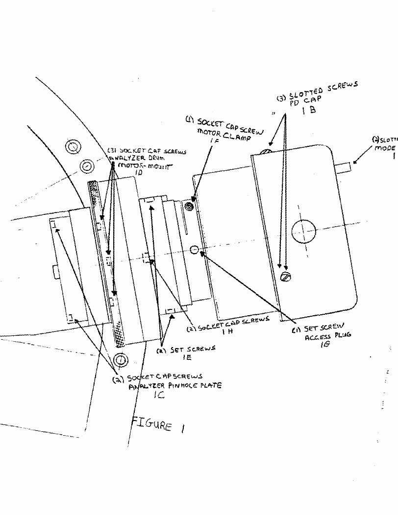
B. Remove the 2 mode switch screws (lA) and loosen the 3 PO cap screws (lE) as in figure 1.
c. Remove PO PD board. board and
cap and disconnect mode switch and cable from Disconnect all cables from bracket below PO
remove bracket from endplate.
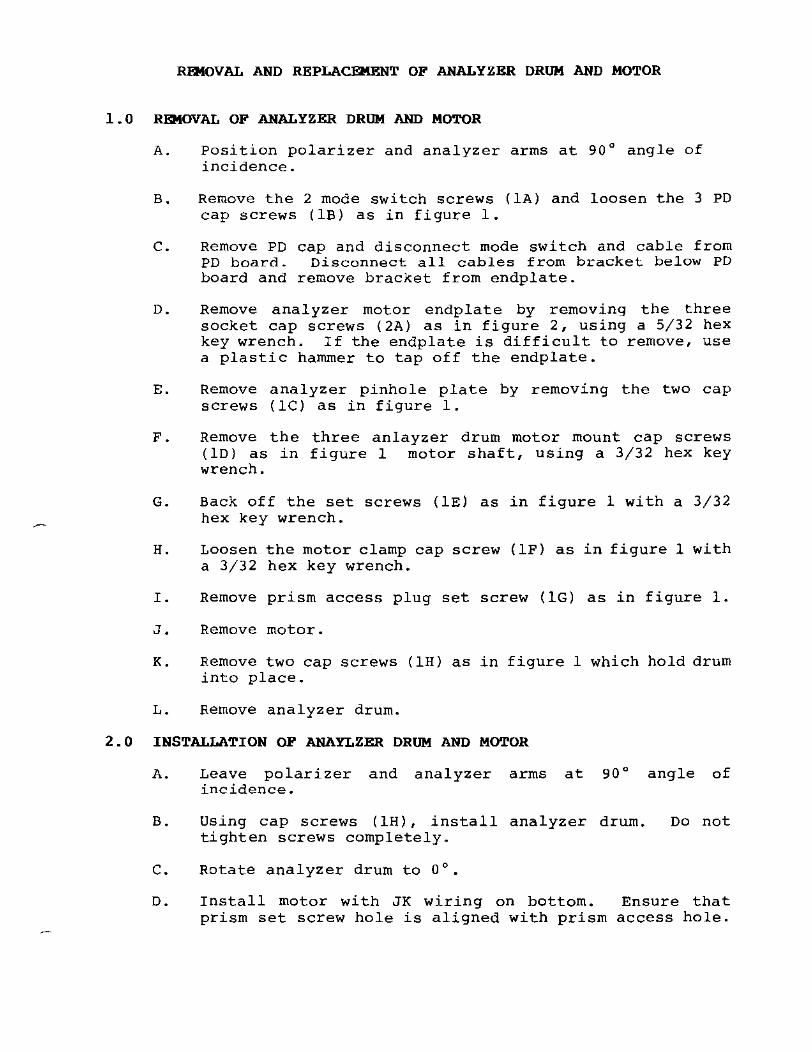
D. Remove analyzer motor endplate by removing the three socket cap screws (2A) as in figure 2, using a 5/32 hex key wrench. If the endplate is difficult to remove, use a plastic hammer to tap off the endplate.
E. Remove analyzer pinhole plate by removing the two cap screws (Ie) as in figure 1.
F. Remove the three anlayzer drum motor mount cap screws (lD) as in figure 1 motor shaft, using a 3/32 hex key wrench.
G. Back off the set screws (IE) as in figure 1 with a 3/32 hex key wrench.
H. Loosen the motor clamp cap screw (IF) as in figure 1 with a 3/32 hex key wrench.
I. Remove prism access plug set screw (lG) as in figure 1.
J. Remove motor.
K. Remove two cap screws (lH) as in figure 1 which hold drum into place.
L. Remove analyzer drum.
2.0 INSTALLATION OF ANAYLZER DRUM AND MOTOR
A. Leave polarizer and analyzer arms at 90° angle of incidence.
B. Using cap screws (lH), install analyzer drum. tighten screws completely.
C. Rotate analyzer drum to 0°.
Do not
D. Install motor with JK wiring on bottom. Ensure that prism set screw hole is aligned with prism access hole.

E. Rotate motor shaft until the three holes in front of motor line up with the three holes in analyzer drum and a prism set screw coincides with the analyzer drum at either 0, 90, 180, or 270°.
F. Push motor inward until housing contacts with analyzer drum. Ensure that the three motor shaft holes are visible through the analyzer drum.
G. Replace cap screws (ID) in tighten cap screws. Tighten which hold the analyzer drum.
front of the two
analyzer drum; cap screws (lH)
H. Ensure that .002" clearance exists between total circumference of analyzer drum halves. I f necessary, move motor housing inward/outward to achieve clearance.
I. Tighten the motor clamp cap screw (IF).
J. Tighten the set screws (IE) on top and bottom of analyzer arm until it touches the motor shaft.
3.0 COARSE ADJUSTMENT OF PRISM EXTINCTION
A. place a target screen at the end of the ellipsometer.
B. Set the polarizer drum to 90° with the analyzer drum at 0°. Slightly rotate analyzer drum to achieve extinction of light.
C. If analyzer vector is greater than 0.4°, reset drum to 0° and, holding drum by hand, loosen 2 prism set screws through the prism access hole and with a prism tool key, rotate prism to achieve extinction. Retighten set screws. Check for prism reflection back to polarizer pinhole plate (orbital). Make adjustment if necessary.
D. If analyzer vector is less than 0.4°, loosen two socket cap screws (lH) which hold drum in place. Tape analyzer drum at 0°. Position the drum until laser extinction occurs on the target. Tighten the two cap screws.
E.
F.
G.
H.
Recheck steps C
Replace
Replace (IC) •
Replace bracket,
extinction. If any difference is and D if necessary.
prism access plug set screw ( IG) •
analyzer
endplate PD board
pinhole plate with the
wi th the 3 cap and mode switch.
screws
found, redo
2 cap screws
(2A) , cable
I. Align PD board for max transmission by adjusting the four

.050 alignment set screws on sides of PD board mount. Laser beam should pass through the center of the PO centering screen.
4.0 FINE ADJUSTMENT OF PRISM EXTINCTION
A. Connect a voltmeter to the red and black test jacks and recheck extinction. Refer to steps 5 and 6 under Prism Check.
B. Replace PO cap and re-tighten the 3 screws (lB) •
C. Replace the 2 mode switch screws (lA) •

@ .. @)"
u \
\
---.
01 ~OCK.G' c:..A;F otCAtw...s I(Al'fZEft DR\,jtr\ l"t'\OTi::},;' ... r(',O:.H lr
ID
/
1\ .. ..,--.-D_
.L ,
\ '.
·0
(~" SlZr Sc..Fle.w$ IE
K&:I Co Af' =.c~tt...J-.S
~'11.~ Pll'/t10(£ rl."TE
Ie
I
.
o
,i' 512\ 5,GRStv AC£..G5S Pl...uu
/6
l: ~D PL ATE
PD BOARD
-----:::::: ......
FIGU RIO. d
LASER INSTALLATION PROCEDURE
1.0 REMOVAL OF MICROSPOT OPTICS
1.1 Refer to the Microspot Removal/Installation Procedure, if so equipped.
2.0 REMOVING A DEFECTIVE LASER
2.1 Turn key-operated Power switch to OFF and disconnect line cord from AC voltage outlet.
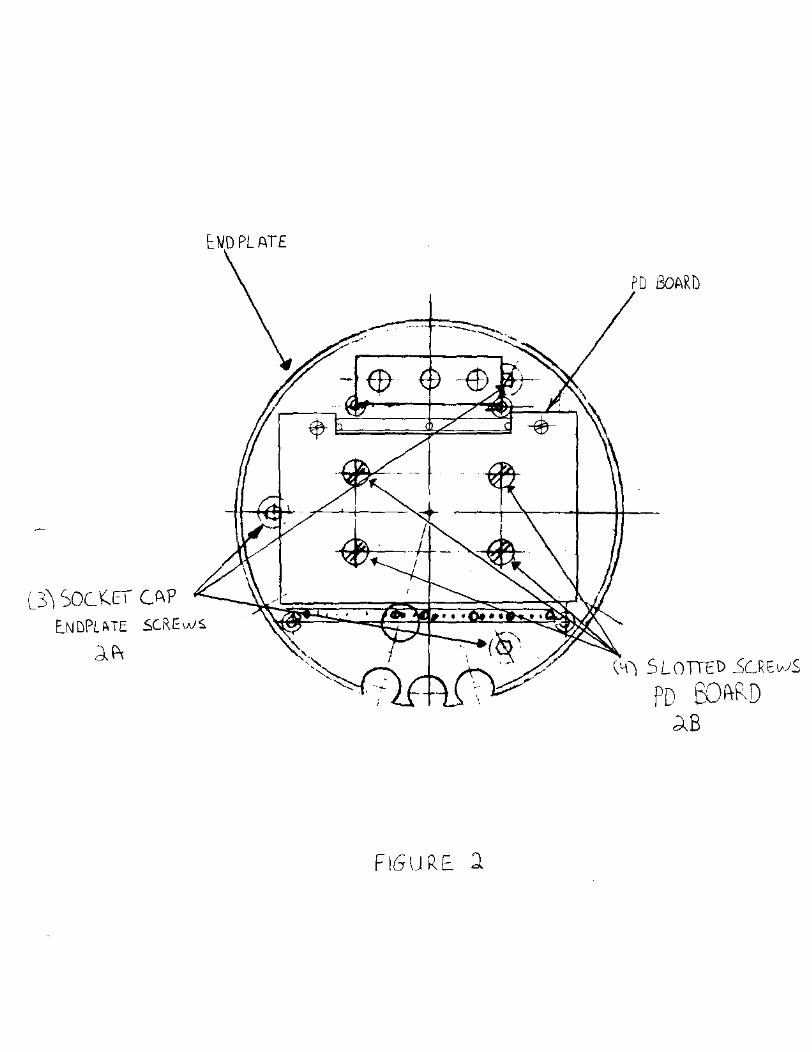
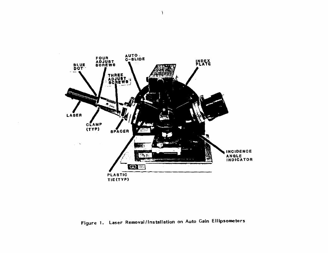
2.2 Detach instrument power supply from rear of index plate (figure 1) by removing four screws, one at each corner of power supply base plate. Carefully lower power supply to surface of work bench.
WARNING
Exercise care in performing step 2.3, as high voltage is present.
2.3 Disconnect the laser power supply from the laser cable. Pull apart the 2-pin white connector. Discharge laser voltage by placing a screwdriver between the two pins.
2.4 Loosen the screw at center of incidence angle indicator (figure 1) and move indicator counterclockwise to allow access to laser cable. Remove all laser cable clamps, cut plastic ties that secure auto C-slide solenoid wire to laser cable and then withdraw laser cable, with attached connector, through the opening located at the bottom of the index plate.
2.5 Using a 3/32-inch hex key, loosen the top screw of the set of three adjust screws (figure 1). Using a 3/32-inch hex key, loosen the top and front screws of the set of four adjust screws (figure 1).
2.6 withdraw laser from mounting arm.
3 • 0 INSTALLING NEW LASER
3.1 If so equipped, remove the protective cap [rom the output end of the new laser.
3.2 Insert laser, with blue decal dot up, into mounting arm until forward end of blue dot (figure 1) is at the edge of the laser mounting arm. Make sure that the two laser attenuator screws are visible through spacer (figure 1).
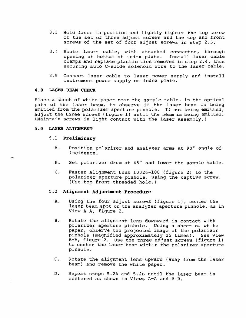
3.3 Hold laser in position and lightly tighten the top screw of the set of three adjust screws and the top and front screws of the set of four adjust screws in step 2.5.
3.4 Route laser cable, with attached connector, through opening at bottom of index plate. Install laser cable clamps and replace plastic ties removed in step 2.4, thus securing auto C-slide solenoid wire to the laser cable.
3.5 Connect laser cable to laser power supply and install inst.rument power supply on index plate.
4 • 0 LASER BEAM CHECK
Place a sheet of white paper near the sample table, in the optical path of the laser beam, to observe if the laser beam is being emitted from the polarizer aperture pinhole. If not being emitted, adjust the three screws (figure 1) until the beam is being emitted. (Maintain screws in light contact with the laser assembly.)
5 • 0 LASER ALIGNMENT
5.1 Preliminary
A. Position polarizer and analyzer arms at 90° angle of incidence.
B. Set polarizer drum at 45° and lower the sample table.
C. Fasten Alignment Lens 10026-100 (figure 2) to the polarizer aperture pinhole, using the captive screw. (Use top front threaded hole.)
5.2 Alignment Adjustment Procedure
A. Using the four adjust screws (figure 1), center the laser beam spot on the analyzer aperture pinhole, as in View A-A, figure 2.
B. Rotate the alignment lens downward in contact with polarizer aperture pinhole. Using a sheet of white paper, observe the projected image of the polarizer pinhole (magnified approximately 25 times). See View B-B, figure 2. Use the three adjust screws (figure 1) to center the laser beam within the polarizer aperture pinhole.
C. Rotate the alignment lens upward (away from the laser beam) and remove the white paper.
D. Repeat steps S.2A and S.2B until the laser beam is centered as shown in Views A-A and B-B.

6aO INSTALLATION OF MICROSPOT OPTICS
6.1 Refer to Microspot Removal/Installation Procedure, if so equipped.
7.0 ADJUSTMENT OF PD GAIN
7.1 For Ellipsometers not equipped with Microspot optics, go to step 7.2. For Ellipsometers equipped with Microspot Optics, refer to PD Gain under Microspot Optics Calibration, then proceed to Step 7.3.
7.2 Set mode switch in AS position and polarizer/analyzer arms to 90° angle of incidence. Set polarizer drum at 45° and the analyzer drum at 105~. When a new laser is installed in an Ellipsometer, the maximum low gain will usually be too low for optimum operation. This can be compensated for by adjustment of a variable attenuator accessible at the spacer. (See figure 1.) The attenuator is adjusted by a push/pull set (cap screw and set screw), having maximum travel of 10 full turns, yielding a total change in intensity of approximately 30 percent. To J.ncrease output, loosen the set screw (counterclockwise) one or two full turns at a time and then tighten cap screw (clockwise) to pull attenuator into contact with set screw. Adjust the attenuator for an output of 90 as observed on the LED meter.
7.3 If ellipsometer is not equipped with Microspot optics, position polarizer and analyzer arms to 70° angle of incidence and check for laser alignment to the monitor viewing scope. Refer to Aliqnment of Sample Monitor Viewinq Scope for any adjustments if necessary.
0-8L"D"
PLAST"'O~=====:----------------------TlE(TVP)
INCIDENCE ANGLE INDICATOR
Figure 1. Laser Removal/Installation on Auto Gain Eilipsometers

LIi.SER iYfOUNT C(R.Cl..E OF.}ACJTuSr ~
SCREWS I Pol ARI'ZGJ?. -PJ Iv' /-IDLE ,/
CIRCLE O~ 4 A (J']"u.sr ------r 1 ScR£WS /
!
• •
/ 11\
iii SER I ,/__ I h.
r-- 11'- - -----_-Jn1" -, : ~ L...-.-----tl_ ---- : iW /'
-"UI,~iJ ;tLlfqNM t:Ni' LEN.s p, N. 10026-100
•
511 M PLE
1 TABU:
~~-'-'-L-[r-A ( 8 ~ 10 r .. -I
iANAL'-IZER. I P/NHOf-~
I I
1 1\ I
II
: i \
I , cl
.... __________ .. ________ . ____ . _____ ----J'
L!l5ER ALlG;NMENT F/GUP[ 2
AP£RiUR~ - __ '~Z=X----RJ!VGDFL!fiHT ",_J
VIEW !I-A CONCENTRIC R.INq of LflS/iR L/~lfT
SIiOWIN~ LASER SpoT C£.VlEld:D ON APERTURE OFANAL't'ZER.P/NHO~£
I'1Rr:.NIFfED -~./" ..
UERTuRE (.
VI r;. w
,-CE NTE R. £ D , / '. (NTENSITY
) /
8-8 MflGNIFIED JMA6iE" O~ POLARI2t~R PINHOLE O/I/SH!ET OF WHITE ,PAPER
5HOWIN" LASER BeAt'i CENTERED
W/THIN APERTuRE
_. __ - SHEET OF WHITE P/fPc-P

1.0
PRISM CHECK
Place parallel plate on sample table. tilt as you would for any other sample. from table.
Adjust table max and Remove parallel plate
2.0 Position polarizer and analyzer arms at 90° angle of incidence.
3.0 Place a Glan-Thompson Prism (GT) on the table (as in figure 2), making sure that the laser is centered through the GT and the reflect.i on back to the polarizer pinhole 1::;: at the 9 o'clock position of the main laser beam.
4.0 Using a voltmeter, place the red test lead into the red jack and the ground lead into the black jack. Close beam shutter, place the mode switch ~n the "M" position and note the voltage. Open beam shutter.
5.0 Rotate the polarizer drum to 90° and the analyzer drum to 0°. Minimum voltage should occur at the 0 ° mark on the vernier scale on the drum, to read a vernier scale, go to instructions under the APPENDIX section. Minimum voltage should be close to the observed voltage with the beam shutter closed.
5.1 If more than .5°:
A. Remove the access set screw plug (lG), as in figure I, with a 3/32 hex key wrench. Insert a .05 hex key wrench into the access plug hole and loosen the prism set screws at 0° and 90° on the analyzer drum. Place the drum at 0° and tape up the drum so that it will not move.
B. Remove the two analyzer pinhole plate cap screws (IC), as in figure I, with a 5/32 hex key wrench and remove the pinhole plate.
C. Using your prism tool key, adjust the prism by rotating it until minimum voltage is achieved.
D. Recheck the prism by rotating the drum around 0° and the minimum voltage should occur at 0° on the 0° mark on the vernier scale. Tighten down the prism set screws and recheck the orbital. Replace the analyzer pinhole plate with its cap screws (lC) •
E. Recheck and repeat if necessary.
F. Replace the access set screw plug (lG).

5.2 If less than .5°:
A. Tape up the drum at 0°, loosen the two cap screws (lH), as in figure I, with a 5/32 hex key wrench that hold the analyzer drum in place. Move the drum back and forth until minimum voltage is achieved on the DVM. Tighten down the cap screws.
B. Recheck at 0°.
C. Recheck and repeat if necessary.
6.0 Next set the analyzer drum to 90° and the polarizer drum to 0 0
•
6.1 Repeat the procedure as in 5.2 if necessary, but adjust the polarizer drum.
A. Call Gaertner Service Department if the polarizer drum is more than .5° off. (312) 281-5335

CHECKING PRISMS WITH A 580 ANGSTROM SAMPLE
1.0 Position polarizer and analyzer arms at 70° angle of incidence.
2.0 Place the 580 angstrom sample on the table, polarizer drum should be at exactly 45°, find TM and set tilt (if it has tilt adjustment) •
3.0
4.0
Remove clamp screw that holds polarizer drum at a voltmeter to the red and black test jack. ground lead into black test jack.
45 0• Connect
Connect the
Set polarizer drum to voltage should occur referring to the Prism
90° and analyzer at 0°, if not Check procedure.
drum at 0°. Minimum adjust as necessary
5.0 Set analyzer drum to 90° and polarizer drum at 0°. Minimum voltage should occur at 0°, if not adjust as necessary, referring to the Prism Check procedure.
1
-~~--- --
, " , \
r, ~.
\ ,
, @; (~\ 5"., ~~.e"'$
("'1'" e'r!:.>'If',c"tw.s F\ ",-U,ER, ?'I'IHOle: nITre
Ie
I
"
--
t ,\ 5"'- SGR ~"J Ac..::.I<!.S p!.ua
IS
(~SLOTTt:.D sc.~
/
MOOE 5WII I A
,

PrJLflRfZ€R..l PINHOLE -
til Sf; f!
·'--------~t~~ ~ ~ -- -" :: i ! LASER B!O p.1Y\
o 0
1----:::1 o· - ._- -
FIGIJPJ: ~
ANAL'T2Ei,. P/NfiOt..G
\

REMOVAL AND REPLACEMENT INSTRUCTIONS OF C-SLIDE
1.0 REMOVAL
Proceed as follows:
A. Place POWER switch to OFF position. Disconnect AC power cord from power outlet.
WARNING
High voltage is present at laser drive our_pnt in instrument power supply.
B. Detach instrument power supply from vertical support by removing four screws, one at each corner of the power supply mounting base. Lower power supply to rest on surface of work area.
C. Disconnect 2-pin, Auto C-Slide connector (figure 1) in power supply.
D. Fully lower sample table. (For LllSA/B/C, WAFERSKAN or Ll16A/B/C equipped with a manual positioning stage, insure that the stage is centered.)
E. Remove the 2 center screws from the incidence angle plate (figure 2), and remove the plate. (Account for wave washer and spacer at pivot point behind the incidence angle plate.)
F. Note that the laser cable and the C-Slide solenoid wiring are lashed together with ties. Cut these ties, being careful not to damage the laser cable. Withdraw the solenoid wiring with the connector through the access hole in vertical support.
G. If the ellipsometer is so equipped, remove the microspots from the vertical support.
CAUTION
If the ellipsometer is equipped with Microspot Optics, the sample table must be fully lowered (as in step D) to prevent microspot projector / receiver damage when performing step H.

H. Position polarizer and analyzer arms at 90° angle of incidence and secure clamp screws.
I. Using a 5/32 hex key wrench, remove the two cap screws (PO, figure 3) that secures the mounting plate (or microspot projector assembly with the mounting plate, if applicable) and the beam attenuator to the polarizer mounting arm.
J. Using a 3/32 hex ky wrench, remove the buttonhead screw (figure 1) and withdraw the C-Slide assembly, including wiring and connector.
2 • 0 REPLACEMENT
Proceed as follows:
A. Position replacement C-Slide assembly in polarizer arm and secure with the buttonhead screw and lockwasher. Tighten sufficiently to be able to move the C-Slide laterally.
B. Route the C-Slide solenoid wiring and connector through access hole in vertical support and plug into 2-pin connector in the instrument power supply. Lash the laser cable and the solenoid wiring approximately at positions unlashed during the C-Slide removal.
C. Secure the instrument power supply to vertical support.
D. place the spacer and the wave washer at pivot point (as shown in figure 2), replace the incidence angle plate into normal position, and insert and tighten the two center screws to secure the plate.
E. Connect AC power line cord to the power outlet. the POWER switch to ON.
NOTE
Allow 30 minute warmup, switch to A position, proceed to Step F.
place and
Mode then
Place
F. Load the GC4A diagnostic program and set up the timing program under the monitor key. Make sure that you are in COMP mode.
G. Exi t out of the monitor setup and press the start key (F9)-timing program should start.
H. The C-Slide will engage, and the PSI should be around 45° .
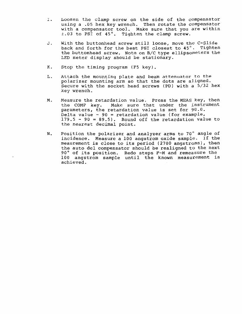
I. Loosen the clamp screw on the side of the compensator using a .05 hex key wrench. Then rotate the compensator with a compensator tool. Make sure that you are within ±.03 to PSI of 45°. Tighten the clamp screw.
J. With the buttonhead screw still loose, move the C-Slide back and forth for the best PSI closest to 45°. Tighten the buttonhead screw. Note on B/C type ellipsometers the LED meter display should be stationary.
K. Stop the timing program (F5 key).
L. Attach the mounting plate and beam attenuator too t_he polarizer mounting arm so that the dots are aligned. Secure with the socket head screws (PD) with a 5/32 hex key wrench.
M. Measure the retardation value. Press the MEAS key, then the COMP key. Make sure that under the instrument parameters, the retardation value is set for 90.0. Delta value - 90 = retardation value (for example, 179.5 - 90 = 89.5). Round off the retardation value to the nearest decimal point.
N. Position the polarizer and analyzer arms to 70° angle of incidence. Measure a 100 angstrom oxide sample. If the meaurernent is close to its period (2700 angstroms), then the auto del compensator should be realigned to the next 90° of its position. Redo steps F-M and remeaSure the 100 angstrom sample until the known measurement is achieved.

LOCATING PINS 180 DEO APART
LOCATION OF BUTTONHEAD SCREW
LOCATION OF CAPSCREWS (2)
180 DEG APA.R
0
00 0 0 0
0
Figure 1. Automatic C-SJide Assembly
- - ,-
•
SCREW (PIVOT PO"N:r>-'
INCIDENCE ANGLE PLATE
WAve WASHER
VERTICAL SUPPORT
Figure 2. Incidence Angle Plate location
, , 0
B C-SLIDE--SOLENOID CONNECTOR
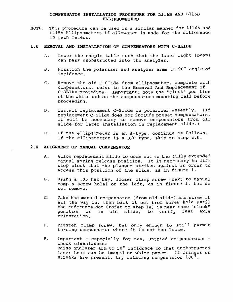
COMPENSATOR INSTALLATION PROCEDURE FOR Ll16B AND LllSB ELLIPSOMETERS
NOTE: This procedure can be used in a similar manner for Ll16A and LllsA Ellipsometers if allowance is made for the difference in gain meters.
1.0 REMOVAL AND INSTALLATION OF COMPENSATORS WITH C-SLIDE
A. Lowe'r the sample table such that the laser light (beam) can pass unobstructed into the analyzer.
B. Position the polarizer and analyzer arms to 90° angle of incidence.
C. Remove the old C-Slide from ellipsometer, complete with compensators, refer to the Removal And Replacement Of C-SLIDE procedure. Important: Note the "clock" position of the white dot on the compensators mounting cell before proceeding.
D. Install replacement C-Slide on polarizer assembly. (If replacement C-Slide does not include preset compensators, it will be necessary to remove compensators from old slide for later installation in replacement slide.)
E. If the ellipsometer is an A-type, continue as follows. rf the ellipsometer is a a/c type, skip to step 3.0.
2.0 ALIGNMENT OF MANUAL COMPENSATOR
A. Allow replacement slide to come out to the fully extended manual spring release position. It is necessary to lift stop block that the plunger strikes against in order to access this position of the slide, as in figure 1.
B. Using a .05 hex key, loosen clamp scre\v (next to manual comp's screw hole) on the left, as in figure 1, but do not remove.
C. Take the manual compensator {from old slide} and screw it all the way in, then back it out from screw hole until the reference dot (refer to step lA) is near same "clock" position as in old slide, to verify fast axis orientation.
D. Tighten clamp screw, but only enough to still permit turning compensator where it is not too louse.
E. Important - especially for new, untried compensators -check cleanliness: Raise analyzer arm to 50° incidence so that unobstructed laser beam can be imaged on white paper. Jf fringes or streaks are present, try rotating compensator 180°.

If these defects are still seen, then use a different compensator.
F. Set polarizer drum for 135° and analyzer drum for 45°.
G. Connect the positive lead of a DVM to the red test jack on the base of the ellipsometer. Connect the ground lead to the black test jack. Rotate compensator with a compensator tool until an absolute minimum is seen on the voltmeter. Adjust gain pot and/or switch over to manual position on the mode swit_ch for more output.
H. When minimum voltage reading is achieved, go to analyzer and polarizer drums and move each very slightly to confirm absolute minimum reading. If either drum is not moved more than about two tenths (of a degree) off of original setting (Step F), then conpensator fast axis is determined.
I. Tighten clamp screw to fix compensator in place.
3.0 ALIGNMENT OF AUTODEL COMPENSATOR
A. Push plunger back such that anvil can fall to normal rest position. Continue to push plunger back so that spring is fully compressed. Secure plunger/slide in this position by wedging a small object between plunger and frame of the slide assembly. (The laser beam should nm..; be passing through the screw hole on the right hand side of the slide.)
B. Loosen clamp screw on the right as in figure 1, but do not remove.
C. Take the auto-del conpensator (from old slide) and screw it in all the way. Finally, allow the plunger/slide to return to spring release position. (NO compensator in path of laser then.)
D. Refer to steps 2 f-n Instructions of C-Slide
ADDENDUM:
under Removal and Replacement to set auto-del compensator.
Before finishing on the ellipsometer, check the retardation value and enter it into the software or GPIQ card if it has changed from before.

STOP I~LCc..r.
LOCATING PINS 180 DEG APART
LOCATION OF BUTTONHEAD SCREW
LOCATION OF CAPSCREWS (2) 180 CEQ APAR
COfm'E.~'::'tl.IoR CLp,ffiP ~d<.cvJ~
o
o
Figure 1. Automatic C-Slide Assembly
I , o
C-SLIDE -SOLENOID CONNECTOR
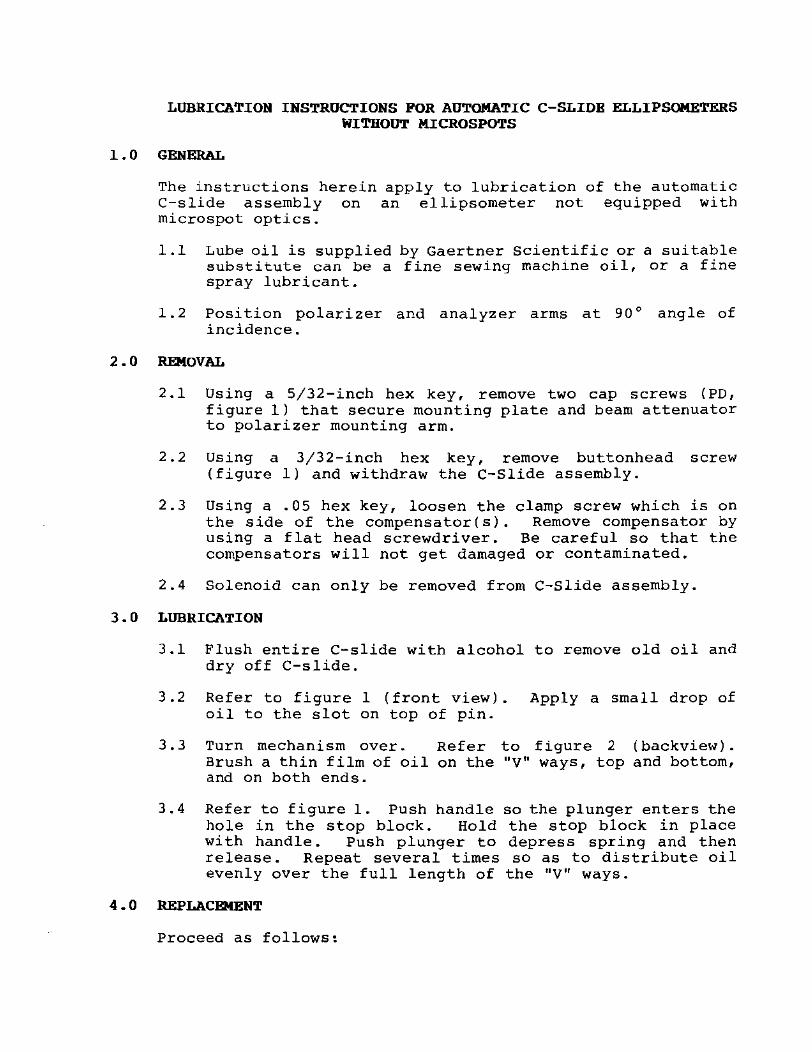
LUBRICATION INSTRUCTIONS FOR AUTOMATIC C-SLIOB ELLIPSQMETBRS WITHOUT MICROSPOTS
1.0 GENERAL
The instructions herein apply to lubrication of the automatic C-slide assembly on an ellipsometer not equipped with microspot optics.
1.1 Lube oil is supplied by Gaertner Scientific or a suitable substitute can be a fine sewing machine oil, or a fine spray lubricant.
1.2 Position polarizer and analyzer arms at 90 0 angle of incidence.
2.0 REMOVAL
2.1 Using a 5/32-inch hex key, remove two cap screws (PD, figure 1) that secure mounting plate and beam attenuator to polarizer mounting arm.
2.2 Using a 3/32-inch hex (figure 1) and withdraw
key, remove buttonhead the C-Slide assembly.
screw
2.3 Using a .05 hex key, loosen the clamp screw which is on the side of the compensator(s). Remove compensator by using a flat head screwdriver. Be careful so that the compensators will not get damaged or contaminated.
2.4 Solenoid can only be removed from C-Slide assembly.
3.0 LUBRICATION
3.1 Flush entire C-slide with alcohol to remove old oil and dry off C-slide.
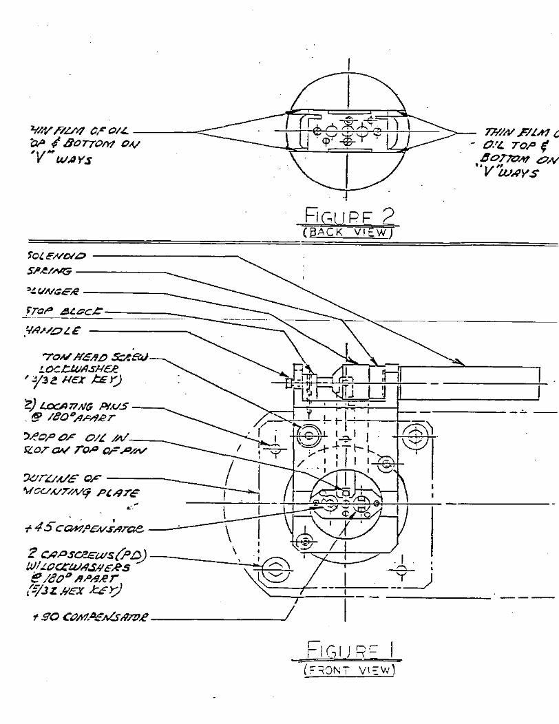
3.2 Refer to figure 1 (front vieW). Apply a small drop of oil to the slot on top of pin.
3.3 Turn mechanism over. Brush a thin film of oil and on both ends.
Refer to figure 2 on the "V" ways, top
(backview) . and bottom,
3.4 Refer to figure 1. Push handle so the plunger enters the hole in the stop block. Hold the stop block in place wi th handle. Push plunger to depress spring and then release. Repeat several times so as to distribute oil evenly over the full length of the "V" ways.
4 • 0 REPLACEMENT
Proceed as follows:
4.1 Position lubricated C-slide assembly in polarizer arm and secure with buttonhead screw.
4.2 Refer to Compensator compensators.
Installation to replace
4.3 Using locating pins, attach mounting plate, with beam attenuator, to polarizer mounting arm such that orientation dots are in line. Ensure that pins are fully seated, and then secure plate with cap screws. (PD figure 1.)
5.0 CALIBRATE WITHOUT MICROSPOT OPTICS
5.1 Refer to Calibration without Microspot optics.

fOUfWo.'O ----------....
S"~/NG -----_
>~(/NG.:,e ---__
rT_C,a __ ~.:.~,;~c~.c~=====
. 70N' Hc/!L) S::?&.J
LOC/::.4llisl-lc;e ry.3e Her ,I::E ~
2) Lot:A77 I-IG P!,v.s ----... . f!!? /eo"';4,c~"er
SZOT a¥ ToP aF p/N' ,.eOI" OF O/~ //I/~;--------------;.{~~t I
FiGlJPF2 (BACK VIEW)
h
':J.:.tr,u.{/E (;!&" -~---_-f.I_J '.ICU,vT/NCj ""'''ire I "" L! ...
'. ,"- ~-T-\\\-! I - ~~Y;:'-/, ~~VJ--, ,. 4S CaH!'cN.I;4rae - ~' 11
7;J;I/tYPU1, - 0.'£ 701" (
4oTlQ,., .oN '·V'WAYS
"-----~-
-----
? O;PScP.£ws(i>~ , Y3\4 : WI.LOCl:WA.£qE~S \.b / _ " I~ e /80" RPRRT '" __ .:±.=-=-= __ =::::::.-. ___ " __ _ (-¥.JZh'EX u>j / I
f so cOJYIAfA(s.97P.e----___ ~
FIGIJ iF I ("" :;or" v 1::- w)

LUBRICATION INSTRUCTIONS FOR AUTOMATIC C-SLIDE ELLIPSQMETERS WITH MICROSPOT OPTICS
1.0 GENERAL
The instructions herein apply to lubrication of the automatic C-Slide assembly on an ellipsometer equipped with microspot optics. The instructions include microspot readjustment procedure.
1.1 Lube oil is supplied suitable substitute can a flne spray lubricant.
by Gaertner Scientific, or be a fine sewing machine oil ,
a or
1.2 Lower sample table fully and remove microspot stops. Position polarizer and analyzer arms at 90° angle of incidence.
2.0 REMOVAL
2.1 Removal of Microspots
A. Refer to Removal and Installation of Microspot Optics.
2.2 Using a 5/32 hex key, remove the two cap screws (PO, figure 1) that secure mounting plate and beam attenuator, to polarizer mounting arm.
2.3 Using a 3/32-inch hex (figure 1) and withdraw
key, remove buttonhead the C-Slide assembly.
screw
2.4 Using a .05 hex key, loosen the clamp screw which is on the side of the compensator(s). Remove compensator by using a flat head screwdriver. Be careful so that the compensators will not get damaged or contaminated.
2.5 Solenoid can only be removed from the C-Slide assembly.
3.0 LUBRICATION
3.1 Flush entire C-Slide with alcohol to remove old oil and dry off C-Slide.
3.2 Refer to figure 1 (front view). Apply a small drop of oil to the slot on top of pin.
3.3 Turn mechanism over. Brush a thin film of oil and on both ends.
Refer to figure 2 on the "V" ways, top
(backview) . and bottom,
3.4 Refer to figure 1. Push handle so the plunger enters the hole in the stop block. Hold the stop block in place with handle. Push plunger to depress spring and then

release. Repeat several times so as to distribute oil evenly over the full length of the "V" ways.
4.0 REPLACEMENT
Proceed as follows:
4.1 Position replacement C-Slide assembly in polarizer arm and secure with buttonhead screw and lockwasher.
4.2 Refer to Compensator compensators.
Installation to replace
4.3 Using locating pins, attach the mounting plate with beam attenuator to polarizer mounting arm such that orientation dots are in line. Ensure that pins are fully seated, and then secure plate with cap screws (PO, figure 1) •
4.4 Replacement of Microspots:
A. Refer to Removal and Installation of Microspot Optics.
5.0 CALIBRATE MICROSPOT OPTICS
5.1 Refer to Calibration with Microspot Optics.
~Oi ENi¥,o ---------""""
S/'~/NG -----_
>~(,/NG€,e ----_
~T_al'_ ~~LO~C~~~========~
'{";h'OLE ------
FiGlJPF2 (BACK VIEW)
FI (,1 J RC I (=-":JNT VI:.W)
m/AlF/LAf, - 0.'£ TOI' (
40770", .oN " V 'WAYS
-~ --

I
/ /
l~A1M A1TTE..¥CI'A1Tt:'J(!
LOI.t)F-e ~ce..:w {i>tV (.O~OH':J( K=;:)
\ ~.MOUAl77NG PLA1Te'
~(Z)CA1r> S~=WS (PI:) _./80 6 Rr>R,eT 75/32 HcJ( J:':>j
FIGURE 3
-__ - O~/evT/9TIOA/_DoTS _--::::-:-
,-- , ~
I --lTT--
I I
. MICROSPOT PROJFCTOR ADJUSTM~NT

CALIBRATION PROCEDURES WITHOUT MICROSPOTS FOR A-TYPE UNITS
1.0 POLARIZER AND ANALYZER ARMS AT 90°
2.0 LASER LASER ALIGNMENT
2.1 Alignment for the analyzer pinhole is with the back 4 set screws on the laser mount.
2.2 Laser Focus is achieved with the 3 front set screws on the laser mount with laser alignment lens in the path of the laser.
3.0 PRISM ALIGNMENT (VECTORS)
3.1 Place Glan-Thompson prism on the table. Laser beam should be positioned in the center of the prism.
3.2 Polarizer drum at 90 0 and analyzer drum at 0°. minimum voltage. Adjust prism if necessary. the Prism Check procedure.
Look for Refer to
3.3 Orbital alignment should be at the 3 o'clock position of the laser beam with one stationary dot and one rotating around the stationary one.
3.4 Polarizer drum at 0° and analyzer drum at 90°. minimum voltage. Adjust prism if necessary. the Prism check procedure.
Look for Refer to
3.5 Polarizer drum at 45°. Remove the Glan-Thompson prism. Turn to the "A" mode position. Load the GC4A program. Readings should be 45 0 within ± .02.
3.6 If necessary, adjust the polarizer drum. Loosen the two socket cap screws with a 5/32 hex key wrench and move the drum back and forth until 45° is achieved. Re-tighten the cap screws.
4.0 LASER POWER AND PO ZERO OFFSET
4.1 Laser power should be around .6mW, adjust with laser attenuator if necessary.
4.2 PD Zero Offset - close beam shutter, mode switch in the "AS" position and gain meter pot at max. Read with red & black test jacks. Should be close to zero volts DC ± .020. Adjust the pd gain pot if necessary.
5.0 C-SLIDE
5.1 Make sure that there are no mechanical hang ups on the CSlide.

5.2 If there is a hang up, remove the C-Slide and clean it with alcohol. (Make sure that the compensator is removed before cleaning.) Relube the rocking arm in back of the C-Slide. Insert the compensator back in.
5.3 Check for retardation value. Follow the procedures 2F-N under Removal and Replacement Instructions of C-Slide.
6.0 ENCODER ADJUSTMENT
6.1 Position the polarizer and analyzer arms to 70° angle of incidence.
0.2 Place an approximately 410 - 500 Angstrom oxide wafer on the sample table.
6.3 Table max & adjust tilt.
6.3 Measure for an index with either noncomp or dual mode.
6.4 Reference your measured index to the actual index of your known sample.
6.5 Adjust the encoder underneath the motor
with a 3/32 on the drum.
6.6 Re-table max and recheck.
7.0 ADJUSTMENT WITH THE 120 ANGSTROM OXIDE
hex key which is
7.1 Place your approximately 120 angstrom sample on the sample table.
7.2 Table max and adjust tilt.
7.3 Fix the index at 1.46 and measure for camp and non-camp modes.
7.4 Measurements should be within 2 angstroms.
7.5 Adjust the A/D pot which is right next to the red test jack. Measure in the non-camp mode.
7.6 Re-table max and recheck.
8.0 REPEAT AND RECHECK
8.1 Repeat procedures 6 and 7 if necessary.
9.0 MEASUREMENT OF SAMPLES
9.1 Measure known samples/wafers to veritfy calibration.

A-TYPE UNITS
1 . GAIN CHECK
A. position polarizer and analyzer arms at 90° angle of incidence.
B. Place polarizer and analyzer drums at 45°.
C. Gain pot on meter at minimum.
D. Read off the gain meter.
2. PD OFFSET
A. Close Beam Shutter.
B. Connect voltmeter into the red and black test jacks.
C. Gain pot at max.
D. Read off meter and should read close to zero volts ±.lOOV DC.

CALIBRATION PROCEDURES WITHOUT MICROSPQTS FOR BIC TYPE UNITS
1.0 POLARIZER AND ANALYZER ARMS AT 90°
2.0 LASER LASER ALIGNMENT
2.1 Alignment for the analyzer pinhole is with the back 4 set screws on the laser mount.
2.2 Laser Focus is achieved with the 3 front set screws on the laser mount with laser alignment lens in the path of the laser.
3.0 PRISM ALIGNMENT (VECTORS)
3.1 Place Glan-Thompson prism on the table. Laser beam should be positioned in the center of the prism.
3.2 Polarizer drum at 90° and analyzer drum at 0°. minimum voltage. Adjust prism if necessary. the Prism Check procedure.
Look for Refer to
3.3 Orbital alignment should be at the 3 o'clock position of the laser beam with one stationary dot and one rotating around the stationary one.
3.4 Polarizer drum at 0° and analyzer drum at 90°. Look for minimum voltage. Adjust prism if necessary. Refer to the Prism Check procedure.
4.0 LASER POWER, PO GAIN AND PD ZERO OFFSET
4.1 Laser power should be around . 6mW, adjust with laser attenuator if necessary.
4.2 PD Gain - Polarizer drum at 45°, analyzer drum at 105°, mode switch in the "AS" position. Using the red & black test jacks, gain should be 9.0-9.4 volts. Adjust the gain pot if necessary. If the pd board has 3 adjustable pots, refer to the High/Low Gain And Pd Offset/Check Adjustment procedure.
4.3 PD Zero Offset - close beam shutter, mode switch in the n AS" position. Read with red & black test jacks. Should be at zero volts DC ± .001 for the "AS and A" mode positions.
5.0 ENCODER AND POLARIZER DRUM ADJUSTMENTS
5.1 Position polarizer and analyzer arms to 70° angle of incidence.

5.2 place an approximately 580 Angstrom oxide wafer on the sample table.
5.2 TM & adjust tilt.
5.3 Measure the sample with either noncomp or dual mode.
5.4 Reference your measured thickness and index to the actuals known sample.
5.5 Load the encoder program, set polarizer drum to 90°, and hit the ENTER key until the measurement cycle begins. Measurements should be 90-270 and 0-180.
5.6 If necessary, adjust the encoder with a 3/32 hex key wrench to achieve the desired measurements. Refer to the figure under Adjustment Of The Encoder Usinq A 400-580 Anqstrom Sample to locate the adjustment screw.
5.7 stop the encoder program by pressing the F5 key.
5.8 Set the polarizer and analyzer arms to 90° angle of incidence. Place the polarizer drum back to 45° and lock in the clamp screw. Set up the Monitor Mode setup for Non-Comp Measurement and I second cycle. Turn to the "A" mode position and press the F9 key to begin measurement cycle. Readings should be 45° within ± .02.
5.9 If necessary, adjust the polarizer drum. Loosen the two socket screws with a 5/32 hex key wrench and move the drum back and forth until 45° is achieved. Re-tighten the socket screws.
6.0 C-SLIDE
6.1 Make sure that there are no mechanical hang ups on the C-Slide.
6.2 If there is a hang up, remove the C-Slide and clean it with alcohol. (Make sure that the compensator is removed before cleaning.) Relube the rocking arm in back of the C-Slide. Insert the compensator back in.
6.3 Check for retardation value. Follow the procedures 2F-M under Removal And Replacement Instructions Of C-Slide.
7.0 ADJUSTMENT WITH THE 120 ANGSTROM OXIDE
7.1 place your approximately 120 angstrom sample on the sample table.
7.2 Table max and adjust tilt.

7.3 Fix the index at 1.46 and measure for comp and non-comp modes.
7.4 Measurements should be within 2 angstroms.
7.5 Adjust jack.
the AID Measure
pot which is right next in the non-comp mode.
7.6 Re-table max and recheck.
8. a MEASUREMENT OF SAMPLES
to the red tes t
8.1 Measure known samples to verify calibration.
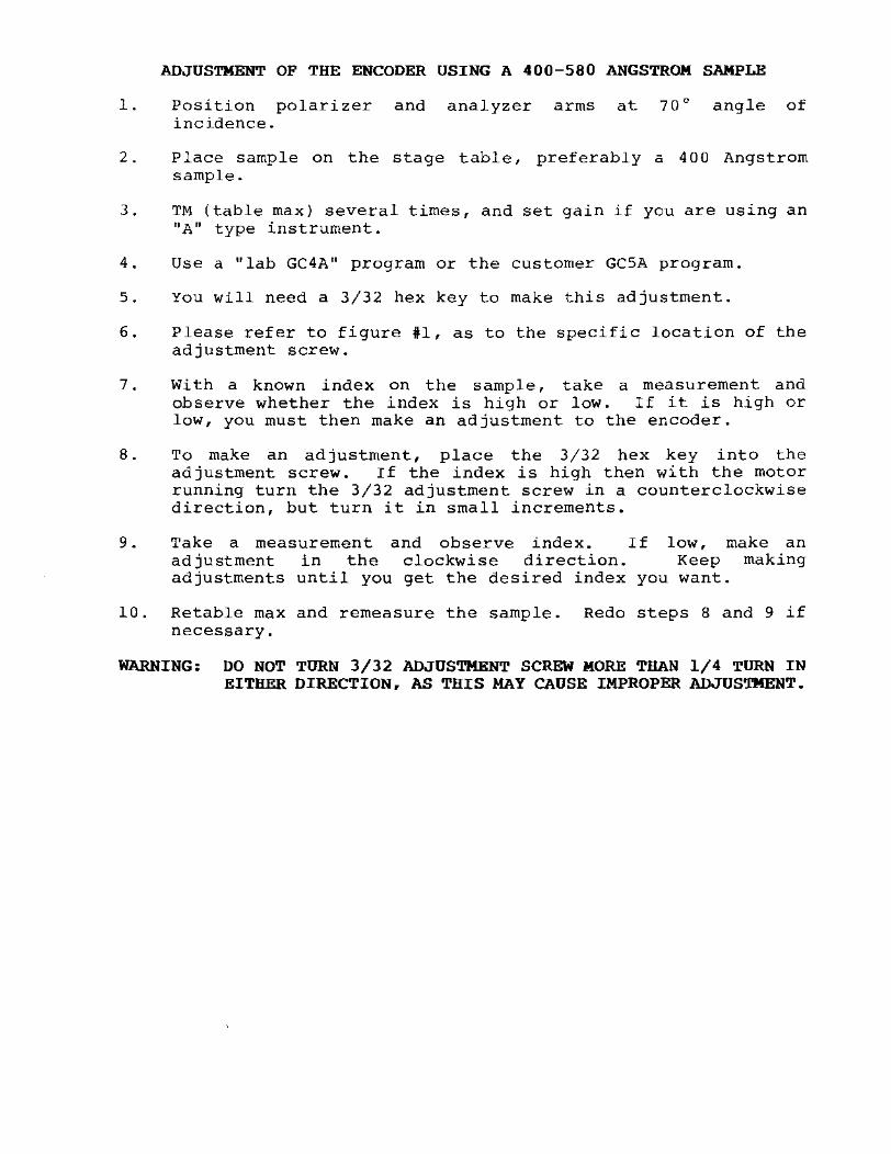
ADJUSTMENT OF THE ENCODER USING A 400-580 ANGSTROM SAMPLE
1. Position polarizer and analyzer arms at 70° angle of incidence.
2. Place sample on the stage table, preferably a 400 Angstrom sample.
3. TM (table max) several times, and set gain if you are using an "A" type instrument.
4. Use a "lab GC4A" program or the customer GCSA program.
5. You will need a 3/32 hex key to make this adjustment.
6. Please refer to figure #1, as to the specific location of the adjustment screw.
7. Wi th a known index on the sample, take a measurement and observe whether the index is high or low. If it is high or low, you must then make an adjustment to the encoder.
8. To make an adjustment, place the 3/32 hex key into the adjustment screw. If the index is high then with the motor running turn the 3/32 adjustment screw in a counterclockwise direction, but turn it in small increments.
9 • Take a measurement and observe index. If low, make an adjustment in the clockwise direction. Keep making adjustments until you get the desired index you want.
10. Retable max and remeasure the sample. Redo steps 8 and 9 if necessary.
WARNING: DO NOT TURN 3/32 ADJUSTMENT SCREW MORE THAN 1/4 TURN IN EITHER DIRECTION. AS THIS MAY CAUSE IMPROPER ADJUSTMENT.

ANALYZER ARM ASSEMBLY
ADJUST THE ENCODER BY USING A 3(32 HEX KEY
BEFORE ADJUSTMENT OF ENCODER, TIGHTEN THE .05 SET SCREW
FIGURE 1
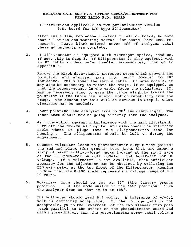
HIGH/LOW GAIN AND P.O. OFFSET CHECK/ADJDSTMENT FOR FIXED RATIO P.D. BOARD
{Instructions applicable to two-potentiometer verSlon P.O. board for B/C type Ellipsometer}
1. After installing replacement detector cell or board, be sure that all wires and mounting screws (for board) have been resecured. Leave black-colored cover off of analyzer until these adjustments are complete.
2. If Ellipsometer is equipped with microspot optics, read on. If not, skip to Step 3. If Ellipsometer is also equipped with an 8" table or has wafer hdndler accessories, then go to Appendix A.
Remove the black disc-shaped microspot stops which prevent the polarizer and analyzer arms from being lowered to 90 0
incidence. Fully lower the sample table. On some models, it may also be necessary to rotate the stage, if so equipped, so that the recess-tongue in the table faces the polarizer. (It may be necessary also to ease the table slightly toward the polarizer if the table has lateral motion capability from the stage. The reason for this will be obvious in Step 3, where clearance may be needed).
3. Lower polarizer and analyzer arms to 90 0 and clamp tight. The laser beam should now be going directly into the analyzer.
4. As a precaution against interference with the gain adjustment, turn off the dedicated computer and disconnect the interface cable where it plugs into the Ellipsometer's base (or housing). The Ellipsometer should be left on during the adjustment.
5. Connect voltmeter leads to photodetector output test points; the red and black (for ground) test jacks that are among a strip of seven multi-colored jacks located at the right side of the Ellipsometer on most models. Set voltmeter for DC voltage. If a voltmeter is not available, then sufficient accuracy for the adjustment can be obtained by utilizing the LED gain meter at the top front of the Ellipsometer, keeping in mind that its 0-100 scale represents a voltage range of 0 -10 volts.
6. Polarizer drum should be position). Put the mode the analyzer drum so that
set at 45° (the switch in the "AS" it is at 105°.
factory preset position. TUrn
7. The voltmeter should read 9.3 volts. A tolerance of +/-0.1 volt is certainly acceptable. If the VOltage read is not acceptable, go to the lowermost of the two slender trim pots (each parallel to the other) on the photodetector board and with a screwdriver, turn the potentiometer screw until voltage
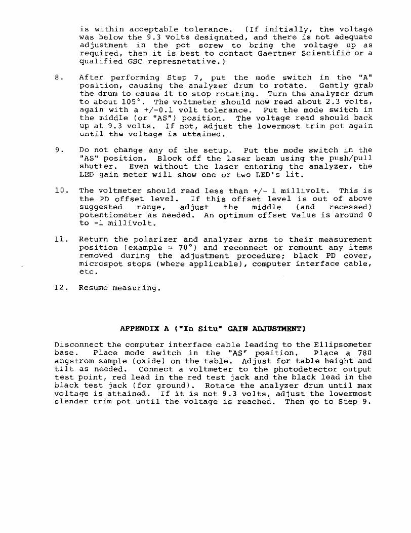
is within acceptable tolerance. (If initially, the voltage was below the 9.3 volts designated, and there is not adequate adjustment in the pot screw to bring the voltage up as required, then it is best to contact Gaertner Scientific or a qualified GSC represnetative.)
8. After performing Step 7, put the mode switch in the "A" position, causing the analyzer drum to rotate. Gently grab the drum to cause it to stop rotating. Turn the analyzer drum to about 105°. The voltmeter should now read about 2.3 volts, again with a +/-0.1 volt tolerance. Put the mode switch in the middle (or "AS") position. The voltage read should back up at 9.3 volts. If not, adjust the lowermost trim pot again until the voltage is attained.
9. Do not change any of the setup. Put the mode switch in the "AS" position. Block off the laser beam using the push/pull shutter. Even without the laser entering the analyzer, the LED gain meter will show one or two LED's lit.
10. The voltmeter should read less than +/- I millivolt. This is the PD offset level. If this offset level is out of above suggested range, adjust the middle (and recessed) potentiometer as needed. An optimum offset value is around 0 to -1 millivolt.
11. Return the polarizer and analyzer arms to their measurement position (example = 70°) and reconnect or remount any items removed during the adjustment procedure; black PD cover, microspot stops (where applicable), computer interface cable, etc.
12. Resume measuring.
APPENDIX A (-In situ· GAIN ADJUSTMENT)
Disconnect the computer interface cable leading to the Ellipsometer base. Place mode switch in the "AS" position. Place a 780 angstrom sample (oxide) on the table. Adjust for table height and tilt as needed. connect a voltmeter to the photodetector output test point, red lead in the red test jack and the black lead in the black test jack (for ground). Rotate the analyzer drum until max voltage is attained. If it is not 9.3 volts, adjust the lowermost slender trim pot until the voltage is reached. Then go to Step 9.
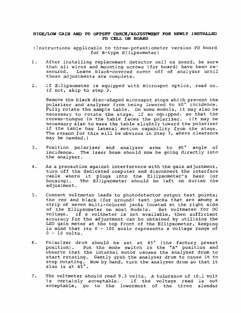
HIGH/LOW GAIN ANO PO OFFSET CHECK/ADJUSTMENT FOR NEWLY INSTALLED PO CELL OR BOARD
(Instructions applicable to three-potentiometer version PO board for B-type Ellipsometer)
1. After installing replacement detector cellon board, be sure that all wires and mounting screws (for board) have been resecured. Leave black-covered cover off of analyzer until these adjustments are complete.
2. If Ellipsometer is equipped with microspot optics, read on.
3 •
If not, skip to step 3.
Remove the black disc-shaped microspot stops which prevent the polarizer and analyzer from being lowered to 90° incidence. Fully rotate the sample table. On some models, it may also be necessary to rotate the stage, if so equipped, so that the recess-tongue in the table faces the polarizer. (It may be necessary also to ease the table slightly toward the polarizer if the table has lateral motion capability from the stage. The reason for this will be obvious in step 3, where clearance may be needed.)
Position polarizer and analyzer arms incidence. The laser beam should now be the analyzer.
to 90° angle of going directly into
4. As a precaution against interference with the gain adjustment, turn off the dedicated computer and disconnect the interface cable where it plugs into the Ellipsometer's base (or housing). The Ellipsometer should be left on during the adjustment.
5. Connect voltmeter leads to photodetector output test points; the red and black (for ground) test jacks that are among a strip of seven multi-colored jacks located at the right side of the Ellipsometer on most models. Set voltmeter for DC vol tage. If a voltmeter is not available, then sufficient accuracy for the adjustment can be obtained by utilizing the LED gain meter at the top front of the Ellipsometer, keeping in mind that its a - 100 scale represents a voltage range of a - 10 volts.
6. Polarizer drum should be set at 45° (the factory preset position). Put the mode switch in the "A" position and observe that the internal motor causes the analyzer drum to start rotating. Gently grab the analyzer drum to cause it to stop rotating. Now by hand, turn the analyzer drum so that it also is at 45°.
7. The voltmeter should read 9.3 volts. A tolerance of ±O.l volt is certainly acceptable. If the voltage read is not acceptable, go to the lowermost of the three slender

potentiometers (each parallel to the other) on the photodetector board and with a screwdriver, turn the potentiometer screw until the voltage is wi thin acceptable tolerance. (If, initially, the voltage was below the 9.3 volts designated, and there is not adequate adjustment in the pot, screw to bring the voltage up as required, then it is best to contact Gaertner Scientific or a qualified GSC representative.)
8. After performing Step 7, turn the analyzer drum to about 105°.
9 •
The voltmeter should now read about 2.3 volts, again with a ±O.l volt tolerance. Put the mode switch in the middle (or "AS") position. The voltage read should be back up to 9.3 volts. If not, adjust the uppermost of the three potentiometers until this voltage is attained.
Adjustments on these two affect one another, so it Steps 6 through 8 until required.
(gain) potentiometers do tend to is generally necessary to repeat all voltage levels are set as
10. Do not change any of the setup. Put mode switch in the "AS" position. Block off the laser beam using the push/pull shutter. Even without the laser entering the analyzer, the LED gain meter will show one or two LED's lit.
11. The voltmeter should read less than ±l millivolts. This is the PD offset level. If this offset level is out of above suggested range, ad just the middle (and slightly recessed) potentiometer as needed. An optimum offset value is around 0 to -2 millivolts.
12. Return the polarizer and analyzer arms to their measurement position (example = 70°) and reconnect or remount any items removed during the adjustment procedure; black PD cover, microspot stops (where applicable), computer interface cable, etc.
13. Resume measuring.

PROCEDURES FOR CHECKING AND ADJUSTING HI-LO GAIN ON "B/C" UNITS USING A 780 ANGSTROM SAMPLE
1. Polarizer and analyzer arms should be at 70° angle of incidence.
2. Place 780 angstrom sample on the stage table, polarizer drum should be at 45°.
3. Find TM and set tilt adjustments as necessary. Set mode switch in the "A" position. Stall the analyzer motor, rotate drum for max light.
4 • Observe LED meter, it should read at 23. 23. Use the gain adjustment pot to make
If this
not, adjust adjustment.
to
5. With the switch in the "AS" position, rotate analyzer drum to obtain a maximum light input. Observe the LED meter, it should read 93, if not then adjust as necessary. Use the gain adjustment pot to make this adjustment.
6. Repeat steps 4 and 5 if necessary.
MICROSPOT OPTICS-REMOVAL AND INSTALLATION PROCEDURE
1.0 PRELIMINARY
1.1 Place the parallel plate on the sample table, table max and tilt as you would for any wafer. Remove the parallel plate.
1.2 Remove microspot stops from index plate.
1.3 If the ellipsometer is equipped with an eight-inch table, refer to Appendix 1 of these instructions.
1.4 Position polarizer and analyzer arms at 90" angle of incidence and clamp in place.
2.0 REMOVAL OF PROJECTOR
2.1 Reference figure 1, the microspot projector has a single matching dot for orientation during installation. The projector should be removed as a complete unit.
2.2 Using a 3/32-inch hex key, back off 2 cap screws PA (f igure 1) unti 1 the projector is free. Remove the projector along with the spacer, if so equipped. In B/C type ellipsometers, there are no spacers.
3 . 0 REMOVAL OF RECEIVER
3.1 Reference figure 1, the microspot revceiver has double matching dots for orientation during installation.
3.2 Use the same procedure as in 2.2 backing off two cap screws (RD).
4.0 INSTALLING ANALYZER PINHOLE
4.1 Insert the small diameter end of the analyzer pinhole into the opening on the analyzer plate. (Light pressure is usually required.) If too loose, apply a thin coat of thick consistency grease to secure pinhole in place. Check for laser alignment. If necessary, refer to the Laser Installation procedure to make any adjusments.
5.0 INSTALLATION OF PROJECTOR
5.1 Position the analyzer arm up to 30" angle of incidence with the polarizer arm still at 90". Place a target screen at the end of the ellipsometer so that the laser light is hitting the center of the target screen. The target screen should consist of cross lines with a center spot and concentric circles.
5.2 Center the (PB) and (PC) screws on the microspot housing. The projector microspot should be centered inside the housing.
5.3 Install projector, aligning the single matching dots. (See figure 1.)
5.4 Using a 3/32-inch hex key, tighten two cap screws PA sufficiently to hold the projector in place, but to allow it to be moved laterally.
5.5 A spot of laser light approximately 10wn in diameter should be seen at the target screen. Center the laser spot to the target screen. Using the (PA) socket head screws, tighten some more but allow to go back if necessary.
5.6 If the spot appears not in focus, adjust the (PC) screws for the sharpest image. Adjust the laser image on the screen to the center spot if necessary. DO NOT ALLOW ANY SCREWS TO REMAIN LOOSE.
5.7 Position the polarizer arm to 70° angle of incidence and clamp in place. Place the parallel plate on the sample table, with the frosted side of the parallel plate, move the plate in a circular motion to see the laser image through the eyepiece. The laser spot should be sharp and focused in the center.
5.8 If the image is not in focus, loosen 2 (PC) set screws that are 90 0 apart and move the projector in and out until the focus is achieved. Retighten the set screws.
5.9 Recheck focus on target screen at 90 0 angle of incidence. Repeat and recheck procedures 5.7 and s.B if necessary.
6.0 ALIGNMENT OF MONITOR
6.1 With the polarizer arm at 70 0 angle of incidence and the parallel plate on the table, through the eyepiece, notice the laser spot image.
6.2 The laser beam should be centered to the crosshairs.
6.3 If not, refer to the Alignment Of Sample Monitor Viewing Scope prucedure to make any adjustments.
7.0 ALIGNMENT OF THE RECEIVER MICROSPOT
7.1 Position the polarizer and analyzer arms down to 90 0
angle of incidence.
7.2 Center the That will housing.
set screws center the
that are labeled (RC) and (RB). receiver microspot inside the
7.3 With the spacer in place, if so equipped, install the receiver microspot, aligning the double matching dots. (See figure 1.)
7.4 Using a 3/32 hex key, tighten two socket head screws (RD) sufficiently to hold the receiver in place, but to allow it to be moved laterally as to obtain maximum output to the meter. Once maximum output is achieved, tighten the socket head screws (RDl complet_ely. Rotate analyzer drum if necessary to obtain more signal on the meter.
7.5 Insert the positive lead from volt meter into the red test jack and the ground lead into the black test jack. Using two .05 hex key wrenches, adjust the four set screws (RB) to obtain max output. Do the same procedure for the (RC) set screws. If the adjustment consists of more than a half of a volt, then remove and realign the receiver microspot once more.
7.6 Loosen the front and top (RC) set screws on the receiver and remove the actual receiver. Using a 5/32 hex key, remove the two socket head screws on the endplate. Remove the endplate and knock out the analyzer pinhole which is on the endplate. Replace the endplate and retighten the socket head screws. Replace the receiver, making sure that it is inserted the same distance as the projector.
7.7 Refer to step 7.4, but adjust only the (RC) screws to find maximum output.
7.8 Remove the photodetector board and center the laser spot so that it is in the center of the photodetector screen. On the sides of the photodetector screen there are set screws, by using two .05 hex keys adjust the laser spot for the X and Y motions. Install the photodetector board.
B.O CALIBRATE WITH OXIDE REFERENCE
8.1 Refer to Calibration Procedure With Microspots.
APPENDIX 1
Before positioning the polarizer and analyzer arms to 90° angle of incidence, follow the procedures as in steps 2.0 through 4.0. Place the stage as far fight as possible and follow the procedures as in steps 5.0 and 6.0. Position the polarizer and analyzer arms to 70° angle of incidence. Due to the eight-inch table, the alignment of the receiver microspot has to be done at 70°. Place the parallel plate on the sample table. Follow the procedures as in steps 7.2 through 8.0.

..... /
I • ,
r==---=-
/ , •
• I. i •
(PB~. . (USE. "lEX' K£'f) I (4SE' ~WS """")
,
L SCREWS(PA)
12CA1! .SCREWS IBO""'AR') USE 3J'.32"H£X KEV)
Jft8tEf,J8R
,
I
/ I
I
I
:J
~ ~ALYZER PINHOLE. -
, , .ANAl YZU\ AJW
INSTAlL fOR LASER
\ ALIGNMENT) . , \
SCOE~~ \
\ (4 'f,TSC' fOP USE • lEX" lIEf) , ,
r:n\ (4", SCRiwS9d'W:f)! \ ("" .05O"He ... "~ ~
\ ,
, 00lJ9l£. MATCHlNG.OOTS
o.AO< PlASTIC ~REws(R.Aj j (2 SCAEWS IAn '",--, .....
8.£CEIVER (RIGHT_SIDELL
. 5
:.....----------11 %REF (9 r8OLIlflUI.!JiliWW) • ". ,"1.
Figure I. Mlcrospot Optics eoq>onents Removaillnstallation
CALIBRATION PROCEDURES WITH MICROSPOTS
1.0 MICROSPOT OPTICS MOUNTING AND ALIGNMENT
1.1 Refer to microspot optics removal and installation procedure.
2 • 0 ADJUSTMENTS OF LASER POWER. PO GAIN r AND PO ZERO OFFSET
2.1 Laser power can be between .4mW up to .66mW.
2.2 Adjust PO gain as you would without microspots.
2.3 PO zero offset should be still set at 0 volts. If not, adjust when necessary.
3.0 INSPECTION OF MICROSPOTS (90· ANGLE OF INCIDENCE)
3.1 With the GC4A diagnostic program, check for PSI and DELTA non-camp measurements. PSI should be around 45° !.2. If not, the microspots should be removed and installed once more.
3.2 Check for retardation value by pressing the MEAS key, then the CQMP key. Make sure that under the instument parameters, the retardation value is set for 90.0. Delta value-90= retardation value.
4.0 ADJUSTMENTS OF MICROSPOT OPTICS ON ACTUAL OXIDE REFERENCES AT 70· ANGLE OF INCIDENCE (1000 ANGSTROMS, 400 ANGSTROMS, 120 ANGSTROMS)
4.1 Adjust microspot projector with the 1000 angstrom oxide sample.
4.1a Make a measurement to determine if the refractive index (NF) is within ±.002
4.1b If necessary, readjust by loosening/tightening the top and/or bottom rnicrospot adjustment screws (PB) as in figure 1 under Microspot optics-Removal and Installation procedures to achieve your refractive index.
4.2 Adjustment of encoder with 400 angstrom oxide. Refer to step 6.0 under Calibration Procedures without Microspots.
4.3 Adjustment with the 120 angstrom oxide. 7.0 under Calibration Procedures Without
5.0 REPEAT AND RECHECK STEP 3.0 IF NECESSARY
Refer to step Microspots.

6.0 RECHECK FOR RETARDATION VALUE
7.0 SECONDARY CHECK WITH OXIDE REFERENCES AND FINAL COLUMN
7.1 Measure standard samples and oxide references. data.
Record

ALIGNMENT OF SAMPLE MONITOR VIEWING SCOPE
1. Position polarizer and analyzer arms to 70° angle of incidence. place parallel plate on sample table, adjust for table max and tilt. Place the parallel plate with its frosted side so that the laser will reflect from it.
2. Course alignment is accomplished by moving the laser spot to the right or left by using set screws MR which are located on the sides of the monitor, using a 1/8 hex key.
3. Fine alignment is accomplished by moving the laser spot to the right or left, using set screws LR and LL, located where shown in figure l, or moving the laser spot backward or forward, using set screws LB and LF, located where shown in figure 1. Each of these set screws are adjusted using a 3/32-inch hex key.
4. To make an alignment adjustment, loosen the cover screw with a 1/16-inch hex key. Proceed with the adjustment left-toright in a manner as described in the following example:
CAUTION
Do not loosen the screw located at position shown in figure 1.
a. Assume that the laser spot of the crosshairs intersect.
b. Back-off set screw LL counterclockwise approximately onehalf turn.
c. Tighten set screw LR clockwise to move the laser spot to the crosshairs intersect.
d. Back-off set screw LR counterclockwise. Repeat step c until laser spot remains centered on crosshair intersect. Once centered, adjust both LR and LL set screws into light contact.
e. Tighten cover screw.
NOTE
For front-to-back adjustment, repeat 4a through 4e except use the LB set screw to move the laser spot backward and the LF set screw to move the laser spot forward.

-
® I - -y
I , , ! "'h,""'''''' ... , "I"" "''''''~'''''''';J II . .. " ..
- \!:J I
::)AHPCC: c:lJ1 gol'//72'A:.._ ~ CONJ'"-eoC-
'" .~~--"'r '" ?t ~
LR./ , , LB ,
® I
w --~
I \ / " ,
ii i
LL
'------------,-_ /' }, I,' 4}'G.,e -~ ,liG':U __ , i -/1
~Hr,:'£-.. T.-:;e'-iF
L L------
,
, . I ,

INSTALLATION
LASER RETAROA TlON (continued 1
Each set of 12 small DIP rocker switches Is divided Into 3 groups of q switches. Each rocker switch Is assigned a weight (1, 2, q or 8) and a logic (switch setting: IION"'open=l; "OFF"/closed=OJ. The logic multiplied by the weight and added to the products (weighted logics) of the other switches In a group determines a "place" digit. The laser retardation value Is obtained by cormlnlng the 3 "place" digits. Rocker switches 1 to .. determine the "tens place"; 5 to 8 determine the "units place"; and 9 to 12 determine the "decimal place". (In the case of 3-w8velength eilipsometers; the I.R. retardation value will be In 1I1e software program.)
Red Laser Retardation (See Figure 5-&)
Assume the red laser retardation Is 96.6. Switch 1 Is open: Its logic. 1. multiplied by Its weight. 8. gives a weighted logic of 8. Switch 4 Is open (logic 1. weight 11; weighted logic Is 1. Switches 2 and 3 are closed (logic 0); weighted logic of each Is o. The total weighted logic of switches 1 to q Is 8+0+0+1=9 ("tens place"). Switches 5 and H are closed: weighted logic o. Switch 6 (weight 41 Is open; weighted logic Is 4. Switch 7 (weight 21 Is open; weighted logic Is 2. The total weighted logic of switches 5 to B Is 6 ("unlts place"). Switches 9 and 12 are closed; weighted logic Is o. Switch 10 (weight 4) Is open; weighted logic Is 4. Switch 11 (weight 21 Is open; weighted logic Is 2. The total weighted logic of switches 9 to 12 Is 6 ("decimal place ll
}.
1523 nm I.R./Blue Laser Retardation (See Figure 5-&1 Assume the IoR./blue retardation Is 103.9. Switches 1 (weight HI and 3 (weight 2) are open; switches 2 iIld 4 are closed. Total weighted logic Is 10 ("tens place"). Switches 5 and 6 are closed; switches 7 (weight 2) and 8 (weight 1) are open. Total weighted logic Is 3 ("units place"). Switches 9 (weight 8J and 12 (weight 1) are open: switches 10 and 11 are closed. Total weighted logic Is 9 (lldecimal place ll ).
830 nm I.R ./Blue Laser Retardation For the diode (Infrared) laser, the value of retardation will be lower (around 70).
Figure 5-&:
WEIGHT
LOGIC >-WEIGHTED LOGIC_
"PLACE" __ ~>~
I.R./BLUE LASER
842 1 8 4 2 1 842 1 )(xxxxxxxxxxx 1 0 100 0 1
10 3 tens units
1 1 0 0 1 9
decimal
RED LASER
842 1 842 184 2 1 x x x 100
9 tens
x x x x x x x x x 101100110
6 & units decimal

OBTAINING A VERNIER SCALE READING
1. To read the irlgular value of the drum, note the number of whole degrees that occur Just below the zero (0) line. In the example, this number Is 56°.
2. locate the two lines which are In closest alignment between the the vernier scale. Note the number of the vernier scale line. line and will be expressed as the decimal 0.5.
drum and the ten 0.10 lines of In the example It Is the fifth
3. Add the numbers found In steps~ 1 and 2 to determine the angular value of the drum.
, 0.5"
5G.O~
56.5" 0
•
8-1

ADJUSTING LED METER
1. Close beam shutter (push in). Switch to the AS mode position.
2. Observe the meter. LED's.
Normally, it will display one to three
A. If not, adjust the ZE meter) . Adjust the obtained.
pot (2nd from pot until a
left in 2 LED
back of the display is
3. position polarizer and analyzer arms to 90° angle of incidence.
4. Open the beam shutter (pullout). Connect a voltmeter to the red and black test jacks.
5. Rotate the analyzer drum until 10 volts is obtained from the voltmeter.
6. The meter should read 100 (full scale).
A. If not, adjust the FS pot (next to the ZE pot) to obtain the 100 LED reading of the meter.

1.
TEST JACKS
Red jack: Photodetector/amplifier offset, gain, prism and compensator
output. checks.
Used for the
2. Orange jack: Reference pulse. Stall the analyzer drum in the A mode position and a voltage of less than 1 volt should occur between 357 and 359.
3. Yellow jack: voltage falls
Count pulse. from 5 volts
It occurs a~ SO intervals. to less than 1 volt.
The
4. Black jack: Common ground for measurement at each test point.
5. Green jack: Peripheral Control (PCTL). A signal to computer indicating a reading is ready for the computer. voltage changes from less than 1 volt to greater than volts.
the The 2.5
6. Blue jack: Peripheral Flag (PFLG). A signal from the computer indicating the computer is ready to accept the reading. The voltage changes from greater than 2.5 volts to less than 1 volt.
7 • Brown jack: pulse. The
Motor pulse. It voltage falls from
occurs right af~er the count 5 volts to less than 1 volt.

TROUBLESHOOTING GUIDE
1. Analyzer drum does not rotate:
A. Check for motor pulse (brown jack).
B. 10 volts on the motor board on the chassis.
C. Bad motor ic chip on the electronic chassis.
* Will not stall: possible bad power supply on chassis, must be at least B to 10 volts.
2. No data (measurement):
A. Ellipsometer must be plugged in.
B. Interface cable connected to the ellipsometer.
C. Analyzer drum is rotating in the A mode position.
D. Check for count and reference pulses.
E. Check for PFLG and PCTL pulses.
3. Unstable readings:
A. Alignment problem of laser.
B. Laser is not centered properly on the PD board.
C. Old or bad laser.
D. Bad laser power supply.
E. Orbital reflection is in the way of the polarizer pinhole (without microspots).
F. Microspots are misaligned.
G. Reference pulse occurs before the motor pulse.
H. Ripple DC voltage on the PD board.
I. Analyzer prii:im: misaligned prism vector, dirty, loose, etc.
J. Bad A/C chip.
K. Loose wires on the chassis or PD hoard.
L. Encoder problem.
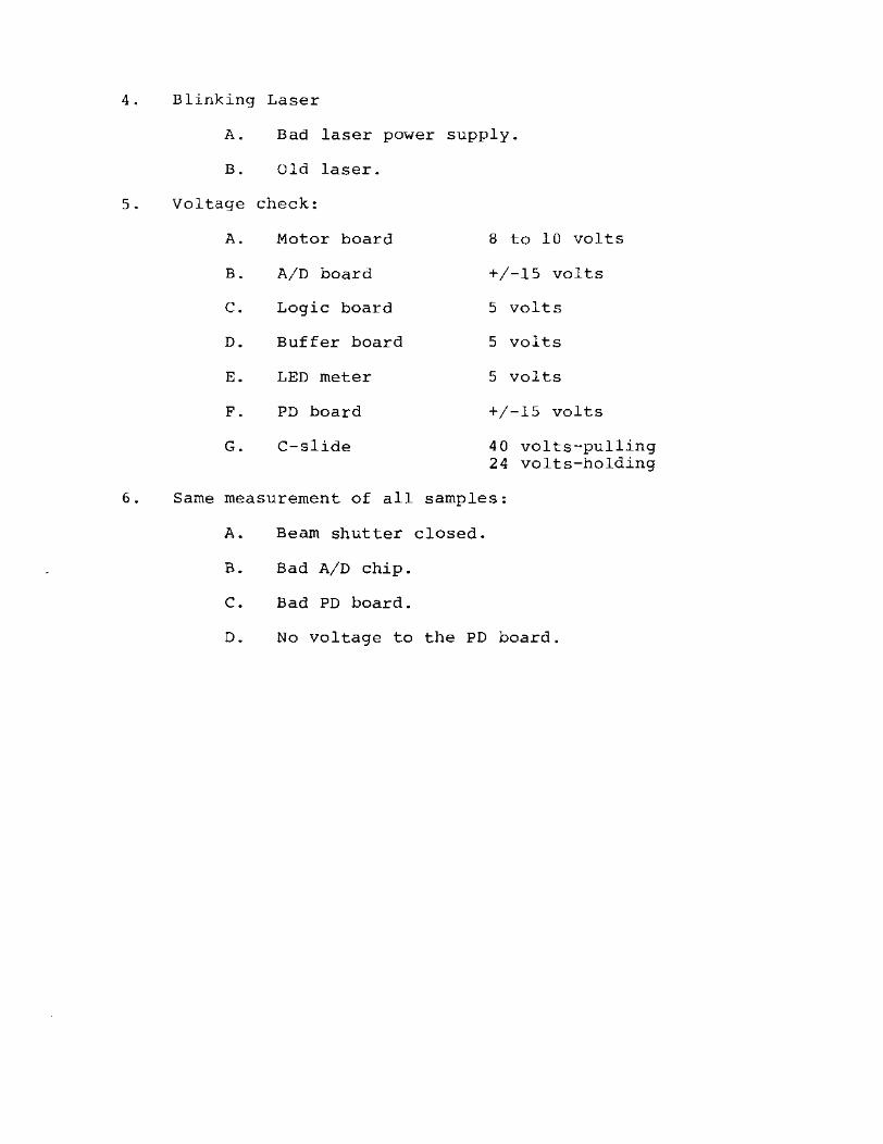
4. B linking Laser
A. Bad laser power supply.
B. old laser.
5 • Voltage check:
A. Motor board 8 to 10 volts
B. A/D board +/-15 volts
c. Logic board 5 volts
D. Buffer board 5 volts
E. LED meter 5 volts
F. PD board +/-15 volts
G. C-slide 40 volts-pulling 24 volts-holding
6. Same measurement of all samples:
A. Beam shutter closed.
B. Bad AID chip.
C. Bad PD board.
D. No voltage to the PD board.

,------- ------1 I P/O I
,----------------------------, I PIO Mora" I
NAlVZER MODULE I • I
I I NCODE"
I I I I I I I I I
OI"TICAl SWITCH
I I I I
®,. I I
i I V
I I T
® I I : : W
@ I I I I I I I I
N
I I @ I I I I I I
ELECTRONIC
T CH .... SSIS I
-Ioomol I
BUfFf:RI I COUNT
110",,0 I
BOARD I
I I
Cf' ($L I I I I
coooo : BO.I'IO
~ .40 I I I I
I I L __________ ~ I I I
I I I I I I
I I I I I I I L _____________ J
I I ,of I,AIIT ~ I I I CONYER,IO I ! ! ". I ...... I I PfTECTOft
AMPL __ I I I I"DOUT
L- I I I L _________________ ~
Built-In Test Points and Intermediate Check Points
MAINTENANCE
• 00 ... Olll'a
!"FLO ~
.'NaIlY OUTI"tJT
• • • • • ~ • 8
DESCRIPTION
" . .. nEil
r I I I ~< ,
J-l-- I
L_
FUll ..... 01 IIEtT
--I I
'il i-[:-~~-"~o,_~_]--- -.. ~g::~~~~.TO" PIC INSTRUMENT I
PW~~~__ __~
r--- --- -] r- ---------- ------------- --, , I I I I I I , I I I , , I I I , I I , I I , I I
PIC ANALYlER MODULE
~ "0 I!'NCODEII "i:ll~ -- -
II l~nDL PIC ELECTRONIC CHASSIS I I .DJ r- --l
II ~ {;: g-II I:: MOTOR 1II0TOil OlllVI' ---~~ --- COfffROUUI flO ."'il.LTUII)
I I I eno
I I I~Tl
Hii IDo; I ·":~"I - "---~f--~ I, ~.' I I .,0 'flG
i i ~-~ ;~~. :,-ru! [:..t""~ II • •
,. 0 II .... ,Pt ~ r--_-~ - -t, .' ENC~~E~ couNT" --- I 1- ~ ~
'---iJlj=======i~'~~~'~.~====== - _'_"_I!~'.!.. u PHOI0DET . ~ PAEAMPL
I I POOUT
I ••
i L-----------------IO'F:~~-." 121llli
L ____ .. ____ _ I 1_" ---~ L ________ _
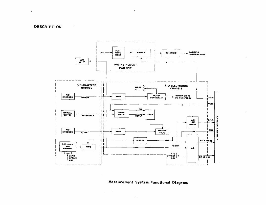
Measurement System Functional Diagram

PROCEDURE FOR CHANGING THE ELLIPSOMETER RETARDATION PARAMETER IN DISC PROGRAMS USED WITH HP 9000 SERIES* COMPUTERS
(i.e.~ models 9816, 9826,9836)
a) Cover the erasure (write protect) slot on the disc housing to unsecure the disc. For SJ.a" disc, however, yOll must uncover the slot.
b) Insert the disc into the disc drive and "boot-up" the computer.
c) Start to run the specific program (file) on which you wish to change the retardation. (If you need to know the file name, first get a listing of files on the disc by typing "CAT" and press EXECUTE.)
dl Press the PAUSE key.
e) Press EDIT and then EXECUTE.
f 1 You will now be in the opening program lines and comment statements for the particular program file you are to edit.
g) Use the cursor keys to move the cursor to the locations you wish to change (edit).
h) The existing entries for the retardation parameter will be denoted in program lines and comment statements by a variable abbreviation such as "Retard=89 .8", or "R(v)=89 .8". (These are just examples.) An exclamation point should be following the retardation value; such as "Retard=89.8!". (If the exclamation point is present be sure that it stays there after you have altered the retardation value.) •••••• You will not usually have to scan through more than the first 150 lines of the program to find all the retardation entries, except in some LllS-Series and L126/L125-Series programs where the retardation entries may be buried as far down as program line #2000, approximately.
i) Once you have the cursor positioned on the program line with the retardation value you wish to modify, simply type in the new value you want. Skip the cursor to the end of that program line and press the ENTER key.
j) Press the CLR LN key.
k) Type "PURGE" and in quotations the file name to be removed from the disc. Example: PURGE "SC6A"
1) Press the EXECUTE key. (The program file you specified will now be erased from the disc. If you get an error indicating "write protected", then you probably forgot to cover the protect slot on the 3~" disc or uncover the protect slot on the 5~ disc.)

m) Press the RECALL key.
nl Now move the cursor back over the PURGE command you just used and type "STORE" over the PURGE.
0)
p)
*
Press the EXECUTE key. (The program file you just modified in the computer's volatile memory will be stored onto the disc.)
Once you have finished modifying (editing) the program files on the disc as you intended, be sure to uncover the erasure (write protect) slot on the disc or cover the erasure slot, so that you do not accidentally erase a file in the future.
For HP disc-based computers the procedure listed above is basically the same, however after you have chosen the specific program file for which you wish to change or verify the retardation parameter, it will be necessary to convert the use of the function keys of the keyboard from the System to the User Mode so that it is possible to get the EDIT function. You should locate a key on the keyboard that permits you to achieve the transition from the System to User Mode (and viceversa) when needed to acquire all the functions (or their renamed equivalents) noted throughout the steps of the above procedure.
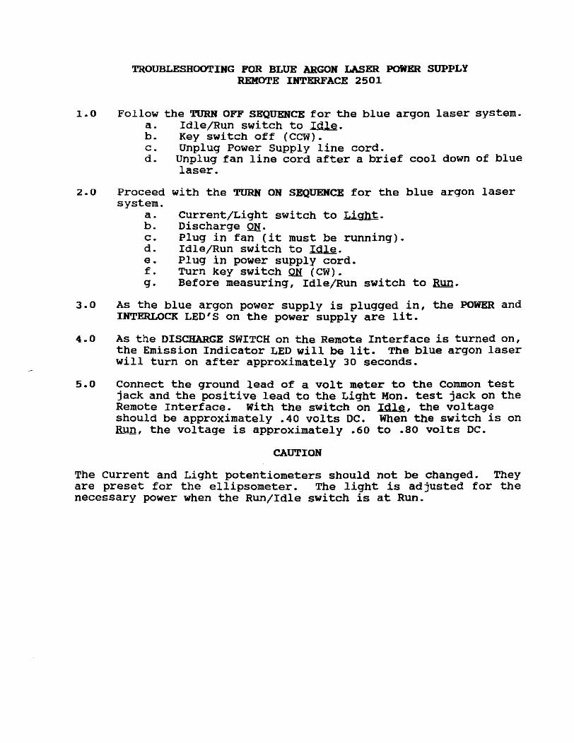
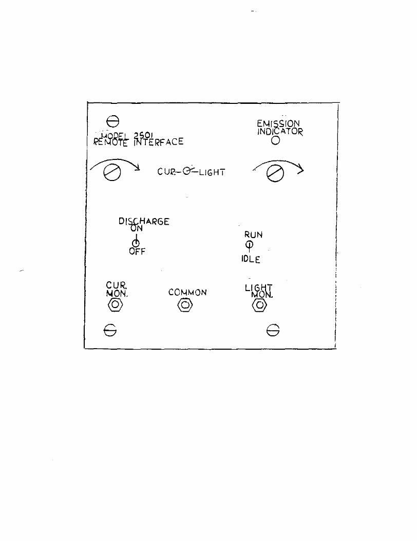
TROUBLESHOOTING FOR BLUE ARGON LASER FOIiER SUPPLY REMOTE INTERFACE 2501
1.0 Follow the TURN OFF SEQUElfCE for the blue argon laser system. a. Idle/Run switch to Ialg. h. Key switch off (CCW). c. Unplug Power Supply line cord. d. Unplug fan line cord after a brief cool down of blue
laser.
2.0 Proceed with the TURN ON SEQUENCE for the blue argon laser system.
a. Current/Light switch to Light. b. Discharge QH. c. Plug in fan (it must be running). d. Idle/Run switch to Idlg. e. Plug in power supply cord. f. Turn key switch QH (CW). g. Before measuring, Idle/Run switch to Run.
3.0 As the blue argon power supply is plugged in, the POWER and INTERLOCK LED'S on the power supply are lit.
4.0 As the DISCHARGE SWITCH on the Remote Interface is turned on, the Emission Indicator LED will be lit. The blue argon laser will turn on after approximately 30 seconds.
5.0 Connect the ground lead of a volt meter to the Common test jack and the positive lead to the Light Mon. test jack on the Remote Interface. With the switch on ~, the voltage should be approximately .40 volts DC. When the switch is on RYn, the voltage is approximately .60 to .80 volts DC.
CAUTION
The current and Light potentiometers should not be changed. They are preset for the ellipsometer. The light is adjusted for the necessary power when the Run/Idle switch is at Run.
e ~~8~r ~tRFACE
~ CUI?-G'"-UGHT
CUR. /.jON. @
G
CO~MON
@
EMISSION INDICATOR
o
RUN <p
IDLE
L~6\J. @
G
, i

en II:
.. w
,.
~~
I-
~
w
~~
:I
l~ II!
~
0
t~ l! ~
~ en "-
f~ -
~~
i ~ ~
\>' ~
..J ..J
\J~ ~
w
~II( ...
~~ H
~\J1Io
~ ..
~ -.:
J~ ~
~ 'b ~
u
~ f
.. ~ ~
I<. 0
N
;0
ill! "I
" N
I\: ~ j::)
a '"
..J
~ ~ ~ ~ Z
Q
~~ ~~
~ "
0 z
~
~ l'4
~
~
<
" u w
...
·z
.. ~
z ...
0 •
u b
l; U
.. N
~~ ;0
N
..J
~~
~ I.l. ..
v ~
~ ~
..... ~
~ ~~
I ~~
en "-
z ~"
( 0 t
~~ ::l
q;: II:
~ Iii
~ ~
z
~
~ -
I ;;!
~ -
I-
~ ~
'" Z
N
W
~
" Q
N
:I ..,
~ I
W
U)
U
..J ~
I ...
~
" .. 0
... -
::l en
'"