G Pipeline Hydraulics.ppt
29
Pipeline Hydraulics
-
Upload
ankitagechaniya -
Category
Documents
-
view
218 -
download
0
Transcript of G Pipeline Hydraulics.ppt

7/22/2019 G Pipeline Hydraulics.ppt
http://slidepdf.com/reader/full/g-pipeline-hydraulicsppt 1/29
Pipeline Hydraulics
7/22/2019 G Pipeline Hydraulics.ppt
http://slidepdf.com/reader/full/g-pipeline-hydraulicsppt 2/29
Importance
Irrigation hydraulics involves:
• The determination of the pressure
distribution in the system
• The selection of pipe sizes and fittings
to convey and regulate water delivery
• The determination of the power and
energy requirements to pressurize and
lift water
7/22/2019 G Pipeline Hydraulics.ppt
http://slidepdf.com/reader/full/g-pipeline-hydraulicsppt 3/29
Basic Relationships
• Q = V m A
f
• Flow rate = (velocity) x (cross-sectionalarea)
• Called the continuity equation
• Units must be consistent • Maximum recommended V in a pipeline is
about 5 feet/second

7/22/2019 G Pipeline Hydraulics.ppt
http://slidepdf.com/reader/full/g-pipeline-hydraulicsppt 4/29
Maximum Flow Rates in Pipelines

7/22/2019 G Pipeline Hydraulics.ppt
http://slidepdf.com/reader/full/g-pipeline-hydraulicsppt 5/29
Energy
• Forms of energy available in water
– Kinetic energy due to velocity
– Potential energy due to elevation
– Potential energy due to pressure

7/22/2019 G Pipeline Hydraulics.ppt
http://slidepdf.com/reader/full/g-pipeline-hydraulicsppt 6/29
Units
• Energy per unit weight of water = "head“
Energy (ft-lb)/Weight (lb) = Head (ft)
• Velocity head; Elevation head; Pressure
head
• Length units (e.g., feet, meters)
7/22/2019 G Pipeline Hydraulics.ppt
http://slidepdf.com/reader/full/g-pipeline-hydraulicsppt 7/29
Velocity Head
• Velocity head =
• g = gravitational constant = 32.2 ft/s2
• when V is 5 ft/s, V2/(2g) is only about 0.4 ft
(usually negligible)
g V 2
2
7/22/2019 G Pipeline Hydraulics.ppt
http://slidepdf.com/reader/full/g-pipeline-hydraulicsppt 8/29
Elevation Head
• Elevation head (gravitational head) = Z
• Height of water above some arbitrary
reference point (datum)
• Water at a higher elevation has more
potential energy than water at a lower
elevation

7/22/2019 G Pipeline Hydraulics.ppt
http://slidepdf.com/reader/full/g-pipeline-hydraulicsppt 9/29
Pressure Head
• Pressure = force per unit area (e.g.,
pounds per square inch)
• Pressure head = pressure per unit
weight of water
• h = P /
– h = pressure head , P = pressure
– = weight of a unit volume of water
• = 62.4 lb/ft3 = 0.433 psi/ft
• 1/ = 2.31ft/psi
• h = 2.31*P (P is in psi; h in ft)
7/22/2019 G Pipeline Hydraulics.ppt
http://slidepdf.com/reader/full/g-pipeline-hydraulicsppt 10/29
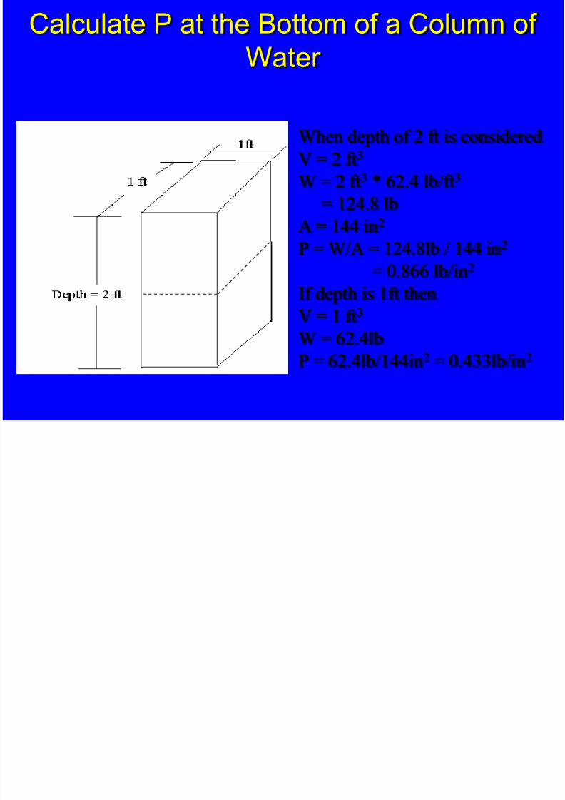
Calculate P at the Bottom of a Column of
Water
When depth of 2 ft is considered
V = 2 ft3
W = 2 ft3 * 62.4 lb/ft3
= 124.8 lbA = 144 in2
P = W/A = 124.8lb / 144 in2
= 0.866 lb/in2
If depth is 1ft thenV = 1 ft3
W = 62.4lb
P = 62.4lb/144in2 = 0.433lb/in2

7/22/2019 G Pipeline Hydraulics.ppt
http://slidepdf.com/reader/full/g-pipeline-hydraulicsppt 11/29
Calculate P at the Bottom of a Column of
Water
V = 2 ft3
W = 124.8 lb
A = 2ft2 = 288 in2
P = 124.8lb / 288in2
= 0.433 lb/in2
The area of a pond or tank does not affect pressure.
Pressure is a function of water depth only.

7/22/2019 G Pipeline Hydraulics.ppt
http://slidepdf.com/reader/full/g-pipeline-hydraulicsppt 12/29
Manometer Rising up From a Pipeline
Pressure, P = lb/ft2
γ = specific weight
of water, (62.4 lb/ft3)
H=P/
7/22/2019 G Pipeline Hydraulics.ppt
http://slidepdf.com/reader/full/g-pipeline-hydraulicsppt 13/29
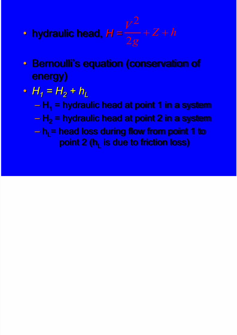
• hydraulic head, H =
• Bernoulli’s equation (conservation of
energy)
• H 1 = H 2 + hL – H1 = hydraulic head at point 1 in a system
– H2
= hydraulic head at point 2 in a system
– hL= head loss during flow from point 1 to
point 2 (hL is due to friction loss)
h Z
g
V
2
2
7/22/2019 G Pipeline Hydraulics.ppt
http://slidepdf.com/reader/full/g-pipeline-hydraulicsppt 14/29
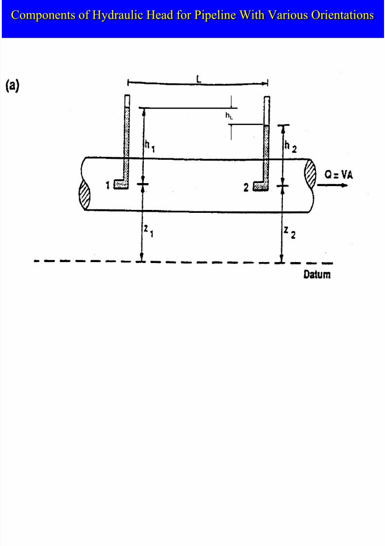
Components of Hydraulic Head for Pipeline With Various Orientations
hL

7/22/2019 G Pipeline Hydraulics.ppt
http://slidepdf.com/reader/full/g-pipeline-hydraulicsppt 15/29
Components of Hydraulic Head for Pipeline With Various Orientations Contd…
hL

7/22/2019 G Pipeline Hydraulics.ppt
http://slidepdf.com/reader/full/g-pipeline-hydraulicsppt 16/29
Components of Hydraulic Head for Pipeline With Various Orientations Contd…
hL
7/22/2019 G Pipeline Hydraulics.ppt
http://slidepdf.com/reader/full/g-pipeline-hydraulicsppt 17/29
Friction Loss
• Description:
– energy loss due to flow resistance as a fluidmoves in a pipeline
• Factors affecting – flow rate
– pipe diameter
– pipe length – pipe roughness
– type of fluid

7/22/2019 G Pipeline Hydraulics.ppt
http://slidepdf.com/reader/full/g-pipeline-hydraulicsppt 18/29
Ways of Calculating Friction Loss
• Equations
– Hazen-Williams is one of many (eq’n 8.8)
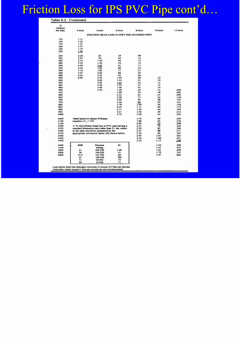
• Tables
– for a given pipe material, pipe diameter,
and flow rate, look up values for friction
loss in feet per hundred feet of pipe• SDR = standard dimension ratio
= pipe diameter wall thickness
Di i l C i f S h 40 Cl 160 d Cl 125 PVC Pi

7/22/2019 G Pipeline Hydraulics.ppt
http://slidepdf.com/reader/full/g-pipeline-hydraulicsppt 19/29
Dimensional Comparison of Sch. 40, Class 160, and Class 125 PVC Pipe
i i f S C i

7/22/2019 G Pipeline Hydraulics.ppt
http://slidepdf.com/reader/full/g-pipeline-hydraulicsppt 20/29
Friction Loss for IPS PVC Pipe
IPS: Iron Pipe Size (same dimensions as steel pipe of same nominal size)
7/22/2019 G Pipeline Hydraulics.ppt
http://slidepdf.com/reader/full/g-pipeline-hydraulicsppt 21/29
Friction Loss for IPS PVC Pipe cont’d…

7/22/2019 G Pipeline Hydraulics.ppt
http://slidepdf.com/reader/full/g-pipeline-hydraulicsppt 22/29
Example Problem
A 4-inch nominal diameter PVC pipe has a
outside diameter of 4.5 inches and a wall
thickness of 0.173 inches. What is the pipe
SDR?
Solution: SDR = Diameter/Wall Thickness
SDR = 4.50/0.173 = 26.0

7/22/2019 G Pipeline Hydraulics.ppt
http://slidepdf.com/reader/full/g-pipeline-hydraulicsppt 23/29
Pipes With Multiple Outlets
• lower friction loss because V decreases with
distance down the pipe
(Q decreases as flow is lost through the outlets; V=Q/A)
• first calculate friction loss as if there were no
outlets, and then multiply by the "multiple
outlet factor", F
M l i l O l F f L l Wi h E ll S d O l f h

7/22/2019 G Pipeline Hydraulics.ppt
http://slidepdf.com/reader/full/g-pipeline-hydraulicsppt 24/29
Multiple Outlet Factors for Laterals With Equally Spaced Outlets of the
Same Discharge

7/22/2019 G Pipeline Hydraulics.ppt
http://slidepdf.com/reader/full/g-pipeline-hydraulicsppt 25/29
Example Problem
A 2-inch diameter, SDR 21 PVC pipe carriesa flow of 60 gpm. The flow is dischargedthrough 15 sprinklers evenly spread along its600-ft length. What is the total head loss in
the pipe?Solution: Hf = 4.62 ft / 100 ft (Table 8.2)
Hf = 4.62 * 600 ft / 100 ft = 27.72 ft
F = 0.379 (Table 8.3; 15 outlets)Hf = 27.72 ft * 0.379 = 10.51 ft

7/22/2019 G Pipeline Hydraulics.ppt
http://slidepdf.com/reader/full/g-pipeline-hydraulicsppt 26/29
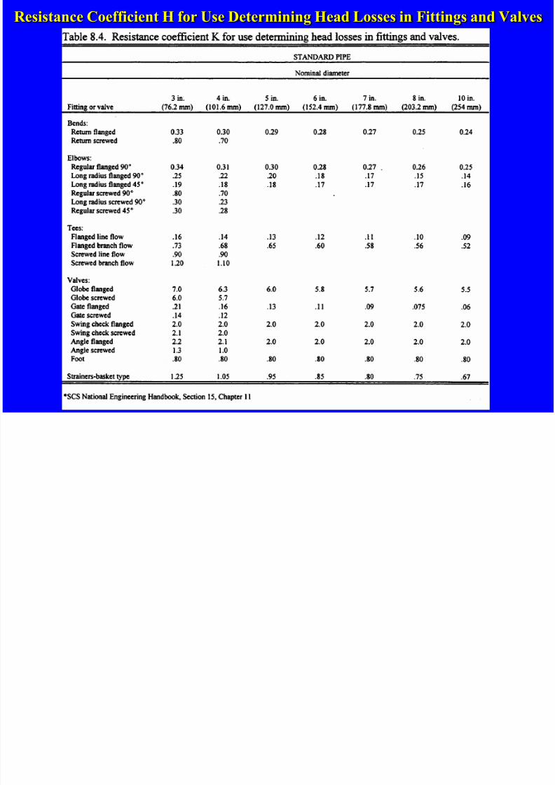
“Minor” Losses
• Source of minor losses
– fittings, valves, bends, elbows, etc
– friction, turbulence, change in flowdirection, etc
– hm = head loss in fitting (ft)
– K = resistance coefficient for fitting
g
V K hm
2
2
R i t C ffi i t H f U D t i i H d L i Fitti d V l
7/22/2019 G Pipeline Hydraulics.ppt
http://slidepdf.com/reader/full/g-pipeline-hydraulicsppt 27/29
Resistance Coefficient H for Use Determining Head Losses in Fittings and Valves

7/22/2019 G Pipeline Hydraulics.ppt
http://slidepdf.com/reader/full/g-pipeline-hydraulicsppt 28/29
Calculation Shortcuts
– V in ft/s
– Q in gpm
– D in inches (INSIDE diameter)
D
Q
V 24085.0
4
2
386 D
Q K hm
– hm in ft – Q in gpm
– D in inches (INSIDE diameter)
7/22/2019 G Pipeline Hydraulics.ppt
http://slidepdf.com/reader/full/g-pipeline-hydraulicsppt 29/29
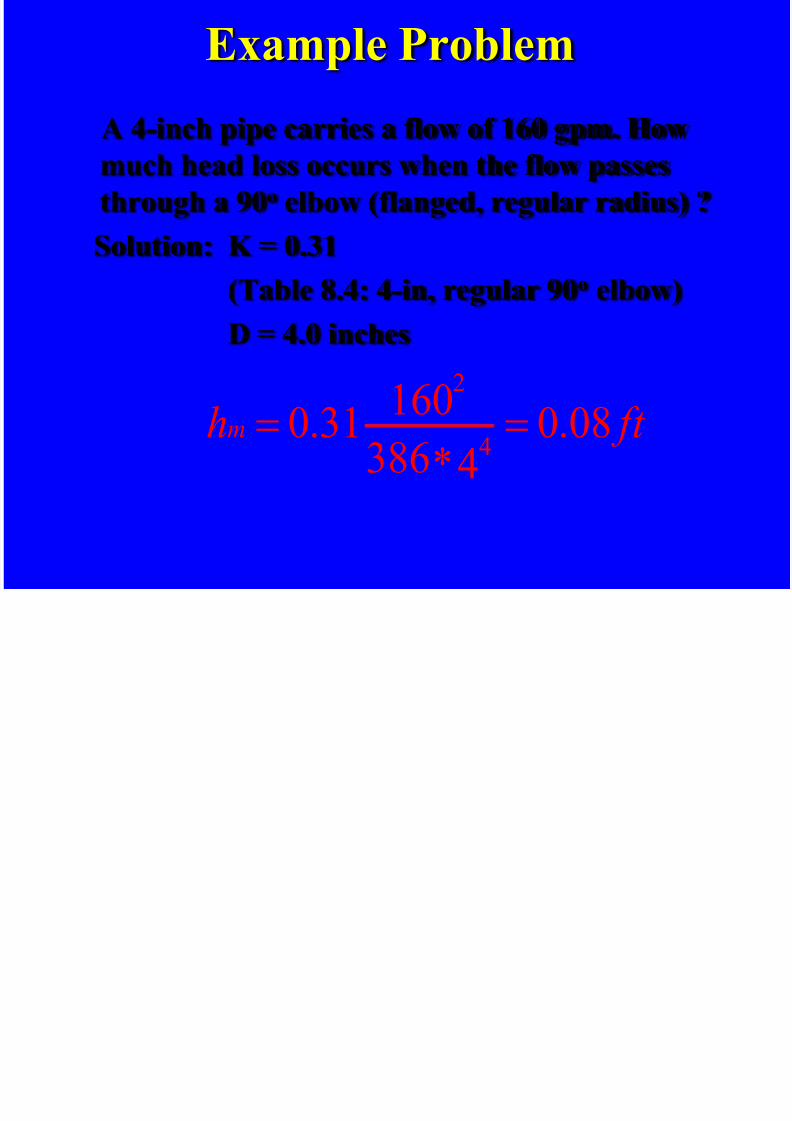
Example Problem
A 4-inch pipe carries a flow of 160 gpm. Howmuch head loss occurs when the flow passes
through a 90o elbow (flanged, regular radius) ?
Solution: K = 0.31
(Table 8.4: 4-in, regular 90o elbow)
D = 4.0 inches
ft hm 08.04*386
16031.0 4
2


![[Pipeline] Inspecting Pipeline Installation](https://static.fdocuments.net/doc/165x107/55cf8d045503462b1391543e/pipeline-inspecting-pipeline-installation.jpg)