((g g )Magnetized Tar get Fusion) · -- shock pre-heating, ... spherical compression A cylindrical...
53
Magneto-Inertial Fusion (Magnetized Target Fusion) or “why should we bother with another ICF driver/target scheme?” G. A. Wurden National Academy of Science IFE Review Panel Albuquerque March 31, 2011 U N C L A S S I F I E D Operated by the Los Alamos National Security, LLC for the DOE/NNSA Slide 1 LA-UR-11-01898
Transcript of ((g g )Magnetized Tar get Fusion) · -- shock pre-heating, ... spherical compression A cylindrical...
Magneto-Inertial Fusion(Magnetized Target Fusion)( g g )
or “why should we bother with another ICF driver/target scheme?”
G. A. Wurden
National Academy of Science IFE Review PanelAlbuquerque
March 31, 2011
U N C L A S S I F I E D
Operated by the Los Alamos National Security, LLC for the DOE/NNSA
Slide 1LA-UR-11-01898

Magneto-inertial fusion:A hybrid approach to fusion….ICF with a twist….magnetic fields
• May allow more efficient drivers, lower cost drivers, lower peak powers,lower implosion velocities, smaller convergence ratios, larger yields,slower repetition rates, easier targeting, the use of non-cryogenic targets,
d d t i l bl (if thi k li id ll ) d id tireduced materials problems (if thick liquid walls), and a wider operating space.
• Not without introducing some issues of its own,…adding a magnetic field, forming a plasma, and making stand-off connections…g g , g p , g…but sometimes having a different set of problems can be a good thing.
In this Talk:
•Adding magnetic fields to conventional ICF can boost performance (LLE, Omega)
•Magnetized Target Fusion (MTF) demonstration, FRCHX at AFRL in Albuquerque
•Plasma Liner Experiment (PLX) under construction at LANL (an idea with stand-off)
•Some MIF-IFE reactor considerations
U N C L A S S I F I E D
Operated by the Los Alamos National Security, LLC for the DOE/NNSA
Slide 2
Some MIF-IFE reactor considerations

A Wide Range of Driver/Target Combinations are possible
Los Alamos / AFRLField Reversed ConfigurationShiva Star FRCHX
U. Rochester LLE Formation inConical Theta
CoilTranslation
Capture
Shiva Star FRCHX~20 s, 0.5 cm/s liner implosion
Direct drive laser implosion of cylinders
Taccetti, Intrator, Wurden et al., Rev. Sci, Instr. 74, 4314 (2003)Degnan et al., IEEE Trans. Plas. Sci 36 80 (2008) ~1 mec d ve se p os o o cy de s
-- shock pre-heating, high implosion velocity
Sandia National Laboratories
M i d Li I i l F i
Gotchev et al., Rev. Sci. Instr. 80, 043504 (2009)
Sci. 36, 80 (2008)
Bzliner
1 m
Los Alamos / HyperVPlasma Liner Experiment
Magnetized Liner Inertial Fusion
Laser preheated magnetized fuel
LASNEX simulations indicate interesting yieldsZ
pMerging plasma jets for remote standoff
ZBL
U N C L A S S I F I E D
Operated by the Los Alamos National Security, LLC for the DOE/NNSA
S. A. Slutz, et al., Phys. Plasmas 17, 056303 (2010) A. G. Lynn, et al, Rev. Sci. Instr. 81, 10E115 (2010)

G. FikselUniversity of RochesterLaboratory for Laser Energetics
Magnetic flux compression and fusion enhancement in magnetized implosions
2006 MIFEDStested
2007 cylindrical compression
first experiments 2008-2009 cylindrical implosionsB-field compression
2010-2011 spherical implosionsfusion enhancement
March 25, 2011R&R Meeting
Neu
tron
Yiel
d (1
09 )
2
3
4
5
6
7
Shell thickness (µm)23.0 23.5 24.0 24.5
B = 0B = 80 kG

Magnetization of plasma electrons inhibits the conduction heat transport
• Particle and energy confinement by magnetic field is the central concept of MCF - tokamaks, stellarators, RFP, etc
• ICF plasma pressure is too high (β = 2µ0P/B2 >>1) so the plasma dynamics and particle confinement are only weakly affected by magnetic field
• However, the heat conduction losses can be reduced and the temperature increased
• If B is high enough so ρLα < rhs alphas can be confined as well
2

Need 10s of megagauss to magnetize electrons
3
k perp/k par
0.01
0.1
1
ωceτe
0.1 1 10
Need 10s of MG to magnetize electrons
Need 100s of MG to confine alphas
ωceτ e >1
ωceτ e <1
Reduction of perpendicular thermal conductivity vsmagnetization ωceτ e
- electron cyclotron frequency- electron collision time
ωce
τ e
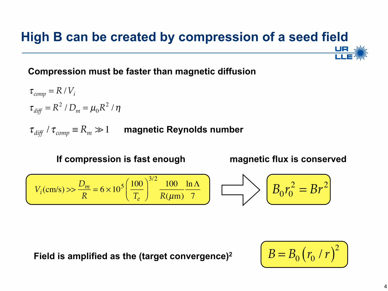
High B can be created by compression of a seed field
Compression must be faster than magnetic diffusion
4
τ comp = R /Vi
τ diff = R2 /Dm = µ0R2 /η
τ diff /τ comp ≡ Rm 1
B = B0 r0 / r( )2
magnetic Reynolds number
Field is amplified as the (target convergence)2
B0r02 = Br2
Vi(cm/s) >>
DmR
= 6 ×10⁵ 100Te
⎛⎝⎜
⎞⎠⎟
3/2100
R(µm)lnΛ7
If compression is fast enough magnetic flux is conserved
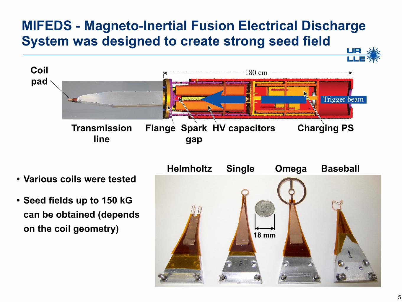
MIFEDS - Magneto-Inertial Fusion Electrical DischargeSystem was designed to create strong seed field
5
Helmholtz Single Omega Baseball
18 mm
HV capacitors Charging PSSparkgap
FlangeTransmissionline
Coilpad
• Various coils were tested
• Seed fields up to 150 kG can be obtained (depends on the coil geometry)

Field compression ~ 500 agrees with flux conservation
6
OMEGAspherical
compression
OMEGAcy
lindr
ical
compr
essio
n
0 50 100 150Seed magnetic field (kG)
Com
pres
sed
mag
netic
fiel
d (M
G)
10
20
30
40
Explosives
• Magnetic field compression ~ 500
• Convergence2 ~ 500
• Magnetic flux is conserved!

Fusion enhancement in spherical implosions was measured in PDD laser geometry
• Single-coil provides stronger seed-fields, less interference with laser paths
• 40 beams were used in a polar-direct-drive setup*
• Implosion uniformity is diagnosed using x-ray BL radiography
• nTOF was used for Ti and neutron yield
7
backlighter target
x-rays2.5 – 4.5 keV
coilcurrent
AuBseed
*F. J. Marshall et al., Phys. Rev. Lett. 102, 185004 (2009)
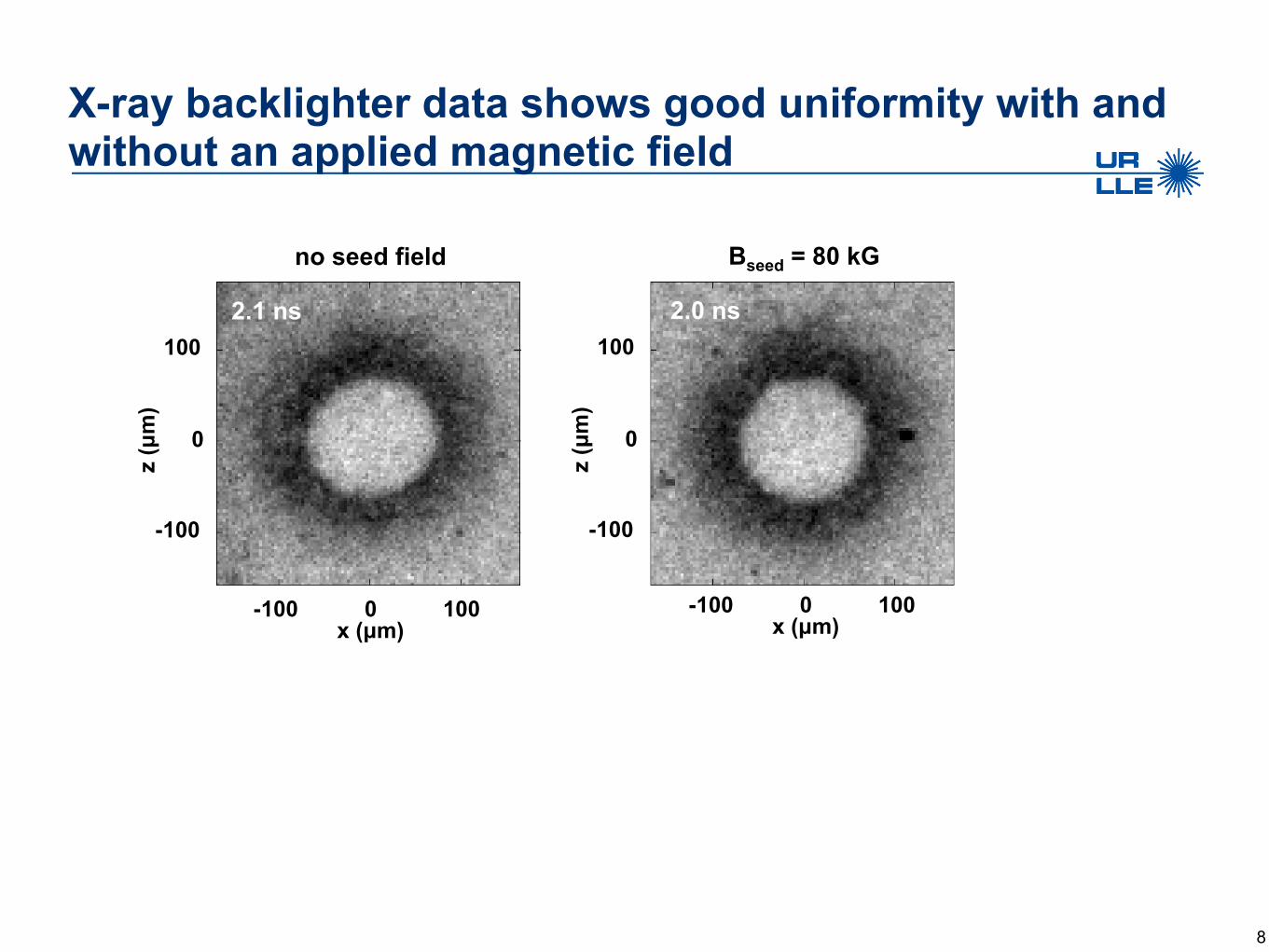
X-ray backlighter data shows good uniformity with and without an applied magnetic field
8
no seed field
x (µm)-100 0 100
z (µ
m)
-100
0
1002.1 ns
Bseed = 80 kG
2.0 ns
z (µ
m)
-100
0
100
x (µm)-100 0 100

We observe a 15% ion temperature increase and 30% fusion yield enhancement for magnetized targets
• Fusion performance scales with shell thickness*
• Linear regression fit reveals clear enhancement of magnetized hot spot performance
9
Neu
tron
Yield (x10
9 )
shell thickness (μm)T i (keV
)shell thickness (μm)
*F. J. Marshall et al., Phys. Plasmas 7, 1006 (2000)
Bseed = 80 kGBseed = 0

The enhancement is small because themagnetic lines are open
• Ratio of open field lines to target surface area = 1/2
• 1D Lilac-MHD is used to simulate equatorial plane of a spherical implosion
• Heat conductivities calculated based on Braginskii coefficients
• Simulations result in 8% increase in Ti and 15% increase in yield
10
heat flux suppression
B
heatlosses
Ti
ρ
ρ (g/cm3)
Tem
pera
ture
(keV
)0
1000
2000
3000
0
10
20
30
40
Radius (µm)0 5 10 15 20 25
Bseed = 80 kGBseed = 0
Lilac-MHD simulation

The FRCHX Team (Albuquerque Meeting, Feb 4, 2011)
C. Grabowski, J. H. Degnan, D. J. Amdahl, R. Delaney, M. Domonkos, F. M. Lehr, P. R. Robinson, E. L. Ruden, W. White, H. Wood
Air Force Research Laboratory, Directed Energy Directorate, Kirtland AFB, NM 87117, USA
D. Brown, D. Gale, M. Kostora, J. McCullough, N. Montano, J. Parker, W. Sommars SAIC, Albuquerque, NM 87106, USA
M. H. Frese, S. D. Frese, J. F. Camacho, S. K. Coffey, V. Makhin NumerEx LLC, Albuquerque, NM 87106, USA, , , y, , q q , ,
T. P. Intrator, G. A. Wurden, J. Sears, P. J. Turchi, T. Weber, and W. J. Waganaar Los Alamos National Laboratory, Los Alamos, NM 87545, USA
R. E. Siemon, B. S. Bauer, S. Fuelling University of Nevada, Reno, Reno, NV 89557, USA
A. G. Lynn, N. F. Roderick, and students University of New Mexico, Albuquerque, NM 87131, USA
U N C L A S S I F I E D
Operated by the Los Alamos National Security, LLC for the DOE/NNSA

Shiva Star is an Air Force pulsed power facility
Shiva Star can store 9 MJ of energy with 1.3 mF of capacitors, at up to 120kV. More typically, at 4.5 MJ, it delivers 12 MA of current to crush a 30-cm tall, 10 cm diameter, 1 mm thick, 300 gm Aluminum cylindrical liner load in FRCHX, which is l d d h f Shi S
U N C L A S S I F I E D
Operated by the Los Alamos National Security, LLC for the DOE/NNSA
5
located under the center of Shiva Star.

Overview of FRCHX* Grabowski, Degnan, et al., APS-DPP 2010 posters
Integrated Technologies• FRC formation, translation, and capture
• Solid liner implosions
• MHD modeling in concert with electromagnetics modeling yields end-to-end simulation with high correlation to experimental hardwarep
• Pulsed power, plasma, and neutron generation diagnostics
Description Research AreasDescription• Magnetized plasma compression provides an
intermediate and low cost approach to HED plasmas
• One application: magneto-inertial fusion pathway
Research Areas• In-depth study of the fundamentals of physics of HED
laboratory plasmas in the presence of high magnetic fieldspp g p y
between ICF and MFE
• Compact toroid (CT) insulates dense hot plasma from low temperature impurity species
• Field reversed configuration is an attractive CT
Magneto-inertial fusion
Studies of particle transport in highly magnetized, dense plasmas
FRC Plasma instabilities
6
• Field reversed configuration is an attractive CT
• Liner implosion to drive compression and heating of the FRC
FRC Plasma instabilities

Choosing the Target• Advantages of Field Reversed Configurations (FRC’s) for
HED plasmas:– Simple cylindrical geometry– High β (β ~ 1) and high power density compact system– Translatable formation and adiabatic heating regions can be– Translatable formation and adiabatic heating regions can be
separated– Natural separatrix diverter – isolation from walls, impurity barrier
7

FRC Translation
• The FRC is ejected from the formation
C tregion by J x Brforces
Fi ld l thFormation in
Translation
Capture
• Fields along the short translation region keep the FRC
Conical ThetaCoil
g pfrom expanding
• Lower and Upper mirror fields form a capture region for the FRC that stops it
~1 m
8
pwithin the center of the liner

Target Plasma Parameters
• Present and Projected FRC Parameters– In formation region of experiment
– n ~ 1017 cm-3
T ~ 100 300 eV– T ~ 100 – 300 eV– Poloidal B ~ 2 - 5 T
– After solid liner compression (Megabar pressures)After solid liner compression (Megabar pressures)– n > 1019 cm-3
– T 3-5 keV– Poloidal B ~ 300 - 500 T
• Initial plasma lifetime confinement time > 10 µs needed
9
• Final plasma lifetime ~ 200 nsec at peak compression

Pulsed Power Systems
• Bias bank Consists of two cap bank modules, ~2.5 mF per module
PI b k Si l 2 1 F it ill ti f f 230 kH• PI bank Single 2.1 µF capacitor, oscillation frequency of ~230 kHz
• Main bank Single Shiva Star bank module, caps turned sideways to reduce bank height (Cupper = Clower = 72 µF); bank is crowbarred near peak current
• Upper and Lower Cusp banks three 500 µF capacitors each switched with ignitrons
10
• Upper and Lower Cusp banks three 500 µF capacitors each, switched with ignitrons
• Guide/Mirror Bank total capacitance of 12 mF, switched with 6 ignitrons
• Shiva Star to drive the liner implosion, 36 modules, ~1.3 mF total C

Magnetized Target Fusion, test of implosion physics
The FRC source/liner assembly (left), a y ( ),MACH2 model of the translating and imploding plasma and liner (middle), and a CAD drawing of the system, including power feeds (right).
U N C L A S S I F I E D
Operated by the Los Alamos National Security, LLC for the DOE/NNSA
11
g p ( g )

Magnetized Target Fusion, test of implosion physics
UNM scientist Alan Lynn adjusting 2-chord fiber interferometer on FRCHX
Actual deformable Aluminum liner for
the next shot.
Project leader Jim Degnan next to remains of the coils from the second engineering test shot. Chief engineer Chris Grabowski by
h C l d k d Shi S
the next shot. (Slotted current
return assemblies in the background)
U N C L A S S I F I E D
Operated by the Los Alamos National Security, LLC for the DOE/NNSA
12
the FRC load stack, under Shiva Star

HEDLP Magnetized Target Fusion, LANL/AFRL FRCHX
Our first full-up systems test was April 16, 2010. An engineering success, with interesting physics, but a failed compression. The second shot in this series is being readied & tested now
U N C L A S S I F I E D
Operated by the Los Alamos National Security, LLC for the DOE/NNSA
shot in this series is being readied & tested now.

FRCHX Test MilestonesPast 12 Months
Event Date Significance Confirmed translation and capture of an FRC plasma in the
Feb 2010
This was the first confirmation of successful FRC translation and capture
extended quartz tube test setup in the AFRL experiment. Densities and temperatures were appropriate for a compression-heating experiment, though lifetimes were short.
Confirmed translation and inferred capture of an FRC plasma in the compression-heating test setup
Apr2010
Confirmation of FRC entry into the liner without observation of any plasma returning from the liner was a pre-requisite for performing the compression h ti t theating test.
Performed first FRC compression heating test
Apr 16,
2010
This was the first ever reported solid liner compression test of an FRC plasma in a laboratory environment.
Confirmed FRC capture with a mock-up of the compression heating test hardware
Sep2010
B-dot probes inserted from above into the liner confirmed, for the parameters that were used in the April 16 test, that plasma was captured in the liner but that th t d fl lif ti t d
14
the trapped flux lifetime, as suspected, ended before compression would have been completed.

B-dot Probe MeasurementsFormation Region
Pre-IonizationBias field rising Pre IonizationBias field rising
Cusp fieldnow applied
Main fieldapplied Main field
crowbarred
• Axial magnetic probe signal shows field vs. time from Bias, Cusp, Pre-Ionization, and Main Theta discharges
15
and Main Theta discharges. • All discharges except that of the Cusp are through the 10-segment Theta coil.

MHD simulation using experimental current agreeswith radiography on liner radius vs time
600 0.35
2500
30000.061E+07
m) nt(A
)400
500
0.25
0.3
2000
2500
0.04
0.05
5E+06
Bz
(T)
Te(e
V)
(k
g/m
3 )
Rad
ius
(m
Circ
uitc
urre
n200
300
0.15
0.2 1500
0 02
0.03
C
100
200
0.05
0.11000
0.01
0.020
Liner inner and outer radii from radiographs
Time (s)0 1E-05 2E-05 3E-05 4E-05
0
NumerX MACH2 results for Shiva Star liner compression for 2 Tesla initial axial magnetic field
U N C L A S S I F I E D
Operated by the Los Alamos National Security, LLC for the DOE/NNSA
Calculated peak field is 540 Tesla

Despite heavy debris damage to digital film we obtained useful radiograph
Implosion - compression experiment radiograph obtained at 22.985 µs after start of implosion discharge current indicates that liner imploded symmetrically, with little or no instability growth,
d hi d 11 ti di l i f iand achieved 11 times radial compression of inner surface. Faraday rotation and inductive current probes indicated ~ 11 MA implosion current with 10 µs rise time.
U N C L A S S I F I E D
Operated by the Los Alamos National Security, LLC for the DOE/NNSA 17 of 32
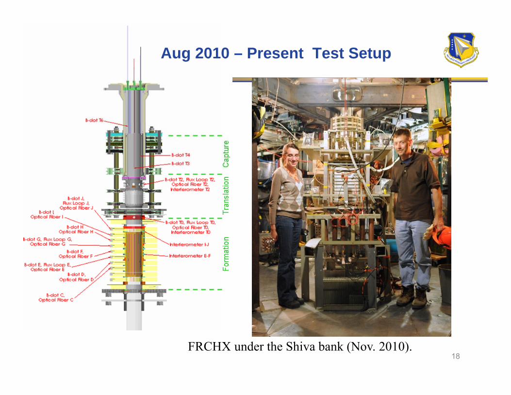
Aug 2010 – Present Test Setup
18FRCHX under the Shiva bank (Nov. 2010).
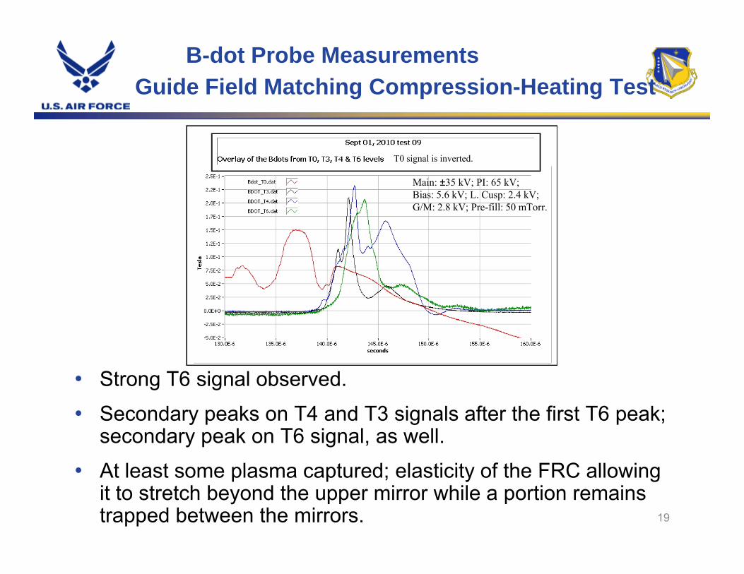
B-dot Probe MeasurementsGuide Field Matching Compression-Heating Test
T0 signal is inverted.
i k kMain: ±35 kV; PI: 65 kV;Bias: 5.6 kV; L. Cusp: 2.4 kV;G/M: 2.8 kV; Pre-fill: 50 mTorr.
• Strong T6 signal observed.
• Secondary peaks on T4 and T3 signals after the first T6 peak; secondary peak on T6 signal, as well.
• At least some plasma captured; elasticity of the FRC allowing
19
• At least some plasma captured; elasticity of the FRC allowing it to stretch beyond the upper mirror while a portion remains trapped between the mirrors.

FRCHX Test Summary
• Numerous FRC formation, translation, injection, and capture experiments have been conducted to characterize FRC T, n, and lifetime with FRCHX.
• Three capture region configurations were implemented:Three capture region configurations were implemented:– An extended quartz tube through the capture region to facilitate
diagnostic access – The complete compression-heating hardware configuration
A k f th li ith difi d l t d d t fl t– A mock up of the liner with modified upper electrode and top flange to allow B-dot probe insertion into the liner
• Plasma T and n have typically been 200~300 eV and 1016~1017cm-3, respectively; trapped flux lifetimes have been only been 6~10 μs in duration. p y; pp y μ
• MHD simulations are being closely coupled to the experiment to aid in improvements.
• The first full-up implosion test (April 16, 2010) was an engineering success. However no useful plasma survived long enough in the capture regionHowever, no useful plasma survived long enough in the capture region.
• A second implosion load assembly is ready, and is being statically tested now off to the side of Shiva Star.
• We are working on longer trapped FRC lifetimes, through higher bank f f
20
settings, better trapping, more uniform preionizaiton. Further modifications will be implemented in the next implosion test in FY11.

Plasma Liner Experiment (PLX) will merge 30 plasma jets to create cm and µs scale plasmas approaching HED conditions (~0.1 Mbar)
Scientific goals: predictive understanding of Scientific goals: predictive understanding of jet propagation/merging, spherical plasma liner formation/convergence/stagnation, and “standoff” magnetization
Motivations: enable platform for discovery-driven HEDLP science, especially magnetized HEDP, and standoff embodiment of magneto-inertial fusion
Status: Phase 1 construction nearing completion with first experiments in 2011
U N C L A S S I F I E D
Operated by the Los Alamos National Security, LLC for the DOE/NNSA
Slide 21
Drawing by David Van Doren, HyperV
completion with first experiments in 2011
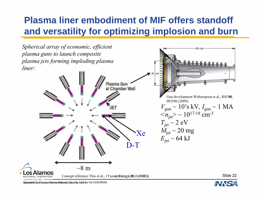
Plasma liner embodiment of MIF offers standoff and versatility for optimizing implosion and burn
Spherical array of economic, efficient plasma guns to launch composite plasma jets forming imploding plasma plasma jets forming imploding plasma liner:
Vgun ~ 10’s kV, Igun ~ 1 MA<n > 1017-18 cm-3
Gun development Witherspoon et al., RSI 80, 083506 (2009).
<njet> ~ 1017-18 cm-3
Tjet ~ 2 eVMjet ~ 20 mgEj ~ 64 kJ
XeEjet 64 kJ
D-T
U N C L A S S I F I E D
Operated by the Los Alamos National Security, LLC for the DOE/NNSA
Slide 22
Operated by Los Alamos National Security, LLC for NNSA
~8 mConcept reference Thio et al., J Fusion Energy 20, 1 (2002).

Jets merge to form imploding spherical plasma “liner”*
Uliner ~ 80 km/s (8 cm/µs)D-TMliner ~ 4 gEliner ~ 13 MJNjet~200
10’ frm~0.5 m
τtransit ~ 10’s of µs
Xe *This is the research Xe objective of LANL’s Plasma Liner Experiment (Njet=30, Eliner≈300 kJ), funded by the DOE Joint Program in
U N C L A S S I F I E D
Operated by the Los Alamos National Security, LLC for the DOE/NNSA
Slide 23
Operated by Los Alamos National Security, LLC for NNSA
HEDLP.

Shortly before reaching peak compression, inner DT portion of plasma liner is magnetized to few Tesla level
D-T (2 layers ofBeat wave current drive Rogers & Hwang, PRL 68, 3877 (1992). D-T (2 layers of
different density-analogous to ICF)
Xe
R~5-10 cm
One possible method: Fire lasers for driving current (via beat wave resonance) and magnetizing the inner DT
U N C L A S S I F I E D
Operated by the Los Alamos National Security, LLC for the DOE/NNSA
Slide 24
Operated by Los Alamos National Security, LLC for NNSA
beat wave resonance) and magnetizing the inner DT portion of the jet (IR, kJ, TW class lasers needed)

Plasma Liner: Final compression amplifies B field to ~50-100 Tesla and heats inner DT layer to fusion temperatures
R fR~0.5 cm Reference case:
DT fusion yield ~ 300 MJTotal liner energy 13 MJ
• Inner DT layer burns (~10% burn-up) Total liner energy ~ 13 MJ
Energy gain > 20Wall plug efficiency ~ 0.5Gain-efficiency product > 10
p)• Aim is to heat and partially
burn the denser outer DT layer (“afterburner”) by ’s and outgoing shock amplifying the Gain efficiency product > 10
At 1 Hz ~300 MW average power (~100 MW electric) Goal is to use thick liquid wall
outgoing shock, amplifying the yield
• Xe layer would reduce radiation losses and enhance qthe confinement time (~1 µs)
U N C L A S S I F I E D
Operated by the Los Alamos National Security, LLC for the DOE/NNSA
Slide 25
Operated by Los Alamos National Security, LLC for NNSA

Reactor Design?Engineering concerns similar to conventional Inertial Fusion Energy
• Pulsed loading
• Chamber survivalChamber survival
• Driver efficiency
• Interface to standoff driver?
• Cost of replaceable parts?
• How to get more tritium breeding?
H t i i i i l ti ?• How to minimize recirculating power?
• Pulsed power reliability (millions of shots)
U N C L A S S I F I E D
Operated by the Los Alamos National Security, LLC for the DOE/NNSA

Reactor Design? Start from the End Point
• Consider a 4.1 GigaJoule yield (1 metric ton) from a pulsed MIF device.
• Consider a rep-rate of 0.1 Herz, which gives more time to clear the chamber.
• Pick a thermal conversion efficiency to electricity of 35%, so one would produce 1.4 GJ electric per pulse (gross, not net), or 140 MW electricity (average).) y ( g )
• Use a thick liquid curtains, with liquid pool at the bottom of the chamber. The liquid will absorb neutrons, and breed tritium. Have voids to dissipate shock from the explosion, and cushion the solid backing wall of the system.
U N C L A S S I F I E D
Operated by the Los Alamos National Security, LLC for the DOE/NNSA

Basic points to consider (1)
3.6 MJoules = 1 kW-Hour
There are 31 5 million seconds in a earThere are 31.5 million seconds in a year.
10 cents/kWH means 1 GigaJoule of electricity is worth $27.8
At 35% conversion efficiency, then 4.1 GJ thermal is worth only $40 of electricity
One metric ton (1000 kg) of high explosive has an energy content of 4.1 GJ
To produce 4.1 GJ from DT fusion, at 17.6 MeV per DT reaction, and 1 eV= 1.6x10⁻¹⁹ Joules, one has 2.8x10⁻¹² Joules per DT reaction; so you need 1.4x10²¹ reactions per 4.1 GJ released.
U N C L A S S I F I E D
Operated by the Los Alamos National Security, LLC for the DOE/NNSA

Basic points (continued) (2)
A mole of D2 is 2x6.02x1023 D atoms, and same for mole of T2. So each 4.1 GJ pulse burns up approximately 1 milliMole of D2, and 1 milliMole of T2. D2 has a molecular weight of 4 grams/Mole and T2 has a molecular weightD2 has a molecular weight of 4 grams/Mole, and T2 has a molecular weight of 6 grams/mole
If the fractional burn-up of DT is 10%, then you need 10 milliMoles of each,If the fractional burn up of DT is 10%, then you need 10 milliMoles of each, in the final compressed MTF plasma. At least 20 milliMoles of each in the beginning target plasma, assuming 50% plasma inventory losses during translation from the formation region. (This exercise will assume no cold fuel g (is available for alphas to burn into).
The initial target fuel load must be “preheated” to 200 eV (Te+Ti). This is an energy investment of 2x(20 x 10-3) x 6x1023 x 200 eV = 4.8x1024 eV, or 0.75x10⁶ Joules, or .75 MJ. Add in a factor of 2x for formation losses, so we are talking 1.5 MJ of energy needed to form the MTF “target” plasma.
U N C L A S S I F I E D
Operated by the Los Alamos National Security, LLC for the DOE/NNSA

Basic points (continued) (3)
Then the gain is 4100 / 1.5 = 2733 relative to the initial plasma energy content. Work also had to be done to compress the initial plasma to get it to the final state. The energy content of the final state is defined to be same number of particles, heated up to 8 keV. The temperature increase (energy content increase) is 8000/200 = 40. Assume the liner drive energy is about 2x the final plasma energy. Then the system has a gain (classic QDT) ~ 34.
If the electric-to-liner drive efficiency is ~50%, the system gain is reduced to ~17, when considered from wall plug to thermal output. (i.e., you needed to put in 240 MJ into the pulsed energy storage to get 4 1 GJ thermal outto put in 240 MJ into the pulsed energy storage to get 4.1 GJ thermal out from pure fusion). If conversion to electricity is 35% efficient, then electricity output is 1.4 GJ, so the minimum recirculating power is about 18% If the rep-rate is 0 1 Hz the average electric output is 140 MW18% . If the rep rate is 0.1 Hz, the average electric output is 140 MW.
So a 10% fractional burn-up is adequate performance from a fusion-only, MTF batch-burn system if the liner coupling efficiency is 50%.
U N C L A S S I F I E D
Operated by the Los Alamos National Security, LLC for the DOE/NNSA
y p g y

Basic points (continued) (4)
For a 10% DT fuel burnup fraction, an nτdwell ~ 2×1015 cm-3sec at 10 keV is required. For example, a final density of 1021 cm-3 and a liner dwell time of 1μsec would do the trick. This exceeds our projected initial experiments by a factor of ~100.
Further points:
•The price of all the destroyed components, accounting for their remanufacture, should not exceed 10% of the value of the electricity produced So a few dollars per pulse is all that is allowedproduced. So, a few dollars per pulse is all that is allowed.
•The value of 100 MW of net electricity, produced for one year, at $0 1/kWH is only ~$100M If you need a 30 year payback time on your$0.1/kWH, is only $100M. If you need a 30 year payback time on your capital equipment, then the plant cost shouldn’t exceed $3B, at zero percent interest! Increasing the rep rate would be a huge win, but you have to be able to reload and clear the chamber between pulses.
U N C L A S S I F I E D
Operated by the Los Alamos National Security, LLC for the DOE/NNSA
p

Looking a little more closely: To have 20% recirculating power, with 50% wall-plug-to-plasma heating efficiency, 35% thermal-to-electric, and some credit from exothermic n-Li reaction, you still need Q ~45
R. A. MillerDecysive Systems
U N C L A S S I F I E D
Operated by the Los Alamos National Security, LLC for the DOE/NNSA

Can the neutron energy multiplier be bigger than 1.1?
•Why is it 1.1 for “pure” fusion?….because we take an exothermicenergy credit for n-Li reactions in a blanket.
•Are there other possibilites? Yes……..Fusion-Fission Hybrids, because each fusion is good at making an energetic neutron, while each low energy neutron can cause a fission event with a lot of energy. The fusion neutron can also first be multiplied, giving even more low energy neutronsgiving even more low energy neutrons.
•If the blanket is 0.6 meter thick hot liquid FLIBE with 10% UF4, one can protect standard solid structural elements for a long life (~30 years), while getting a tritium breeding ratio of >1.1, and an energy amplification of 1.9 (due to fission in the blanket!). [Mustafa Ubeyli, Journal of Fusion Energy, Vol. 25, no. 1-2, pg 67-72, (2006)]
•So, as most of us know, if you are willing to be a fissile breeder, it is easy to double the Q.So, as most of us know, if you are willing to be a fissile breeder, it is easy to double the Q.
• The caveat of course, is all the issues associated with having a fissile blanket sitting around your chamber….
U N C L A S S I F I E D
Operated by the Los Alamos National Security, LLC for the DOE/NNSA
Thick liquid wall recirculation is not a big energy hit
• The chemical composition of pure FLIBE is Li2BeF4.
• If the chamber size is a cylinder with a radius of 3 meters and similar length then• If the chamber size is a cylinder, with a radius of 3 meters, and similar length, then the minimum amount of hot FLIBE out on the wall, is about 35 cubic meters.
• FLIBE has a density of 2 gm/cc, or 8.5x10^22 atoms/cc. This is an exposed blanket inventory of about 7x10⁴ kg, or 70 metric tons. If it “falls” under gravity, a distance of, say, 5 meters, then the gravitational potential energy MgH is 3.5 MJ. Under gravity free-fall, it also takes only 1 second for this material to fall 5 meters.
• So you will need to invest 3.5 MW, or even twice that, continuously, to keep it circulating, which adds to the recirculating power we have already discussed, but for our assumed 140 MW average electric power output, is not a big issue relative to h i d l dthe required pulsed power energy storage.
U N C L A S S I F I E D
Operated by the Los Alamos National Security, LLC for the DOE/NNSA

Previous liner implosion solutions: Fast Liner Reactor
A.R. Sherwood, B.L. Freeman, R.A. Gerwin, T.R. Jarboe, R.A. Krakowski, R.C. Malone, J. Marshall, R.L.Miller, B. Suydam
Los Alamos Scientific Laboratory proposal, LA-6707-P, (1977)Title: Fast liner proposal
Abstract: This is a proposal to study, both theoretically and experimentally, the possibility of making a fusion reactor by magnetically imploding a cylindrical metallic shell on a prepared plasma. The approach is characterized by the following features: (1) the non-rotating liner would be driven by an axial current, (2) the plasma would also carry an axial current that provides an azimuthal magnetic field for thermal insulation in both the radial and longitudinal directions, (3) solid end plugs would be utilized to prevent axial loss of particles, and (4) liner speeds would be in the 10^6 cm/s range. Our preliminary calculations indicate (1) that the energetics are favorable (energy inputs of about 10 MJ might produce a machine in the break-even regime), (2) that radiation and heat losses could be made tolerable, (3) that alpha-particle heating could be made very effective, and (4) that Taylor instabilities in a fast liner might be harmless because of the large viscosities at high pressures. A preliminary conceptual design of the sort of fusion reactor that might result from such an approach is discussed, as are some of the relevant reactor scaling arguments.
U N C L A S S I F I E D
Operated by the Los Alamos National Security, LLC for the DOE/NNSA

LANL Fast Liner Power plant schematic (Krakowski, et al. ~ 1980)
U N C L A S S I F I E D
Operated by the Los Alamos National Security, LLC for the DOE/NNSA

Acoustic piston drivers for MTF: General Fusion (Vancouver, Canada)
U N C L A S S I F I E D
Operated by the Los Alamos National Security, LLC for the DOE/NNSA
Popular Science, pg. 64-71, Jan. 2009

Sandia Z-IFE Power Plant Schematic (Craig Olson, et al.)
U N C L A S S I F I E D
Operated by the Los Alamos National Security, LLC for the DOE/NNSA

One vision of an MTF reactor, with miscible materials
IM-1 01-0659 (4/01)
• All target material recycled
15 sec per pulse Structural •15 sec per pulse
• Flibe primarycoolant at 550 oC SolidSolid
Steel
Tin
insulator
coolant at 550 C(Tmelt = 459 oC)
• Tin Tmelt = 232 oC
SolidSolidFlibeFlibe
Tin
melt 3 C
• P. Peterson, UC Berkeley, ~1998
MoltenMoltenFlibeFlibe
FusionFusionBurstBurst
~4 metersU N C L A S S I F I E D
Operated by the Los Alamos National Security, LLC for the DOE/NNSA
4 meters
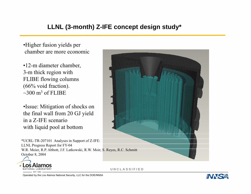
LLNL (3-month) Z-IFE concept design study*
•Higher fusion yields perchamber are more economic
•12-m diameter chamber,3-m thick region with FLIBE flowing columns(66% id f ti )(66% void fraction).~300 m3 of FLIBE
•Issue: Mitigation of shocks on gthe final wall from 20 GJ yieldin a Z-IFE scenariowith liquid pool at bottom
*UCRL-TR-207101 Analyses in Support of Z-IFE:LLNL Progress Report for FY-04W.R. Meier, R.P. Abbott, J.F. Latkowski, R.W. Moir, S. Reyes, R.C. SchmittOctober 8, 2004
U N C L A S S I F I E D
Operated by the Los Alamos National Security, LLC for the DOE/NNSA
Differences & similarities between MTF and Z-IFE reactors
•Both envision reactors with multi-GJ yields, and probably liquid first walls
•Both envision slower rep rates (~0.1 Hz) than conventional IFE, with resultant advantagesin clearing the chamber and setting up the targetin clearing the chamber and setting up the target
•Both require target standoff delivery of energy to the imploder (liner/wire array)
•Neither requires target tracking in the reactor chamber
•Z-IFE expects higher Q (due to burning cold-fuel) than batch-burn MTF
•MTF delivers energy on slower timescales, with lower driver voltages, than Z-IFE
•MTF compression ratios and implosion velocities are smaller than needed by Z-IFE
•MTF needs a higher quality vacuum (for its target plasma) than Z-IFE
•It may be possible to combine magnetic insulation with a Z-IFE target
U N C L A S S I F I E D
Operated by the Los Alamos National Security, LLC for the DOE/NNSA
y p g g

Summary: Key Issues
With Magnetized Target Fusion:
• Q of ~40 is needed (if pure fusion), or alternatively better Q of 40 is needed (if pure fusion), or alternatively better than 10% fractional burn-up of DT fuel.
• Reliable (millions of pulses, MTBF) pulsed power switching and energy storage components
• Liquid blanket development, liquid wall handling and chemical separation technologies
• So-called “recyclable transmission line”/ driver stand-off system demonstrationsystem demonstration
-- but not fusion materials development-- but not target tracking
U N C L A S S I F I E D
Operated by the Los Alamos National Security, LLC for the DOE/NNSA
-- but not target tracking

Additional References
R. Moir “The logic behind thick, liquid-walled, fusion concepts”. LLNL UCRL-JC-115748, 1994.
R. W. Moir, R. H. Bulmer, K. Gulec, P. Fogarty, B. Nelson, M. Ohnishi, M. Resnick, T. D. Rognlien, J. F. Santarius, and D. K. Sze, “Thick Liquid-Walled, Field-Reversed Configuration Magnetic Fusion Power q g gPlant,” Fusion Technology, 2, 2, Part 2 (March 2001) 758.
R. W. Moir, R. L. Bieri, X. M. Chen, T. J. Dolan, M. A. Hoffman, et al., “HYLIFE-II: A Molten-Salt Inertial Fusion Energy Power Plant Design-Final Report,” Fusion Technology, 25, 1 (January 1994) 5-25.
R. W. Moses, R. A. Krakowski, and R. L. Miller, “Fast-Imploding-Liner Fusion Power,” Proceedings of the Third Topical Meeting on The Technology of Controlled Nuclear Fusion, Vol. 1, 109 (May 1978) CONF-780508.
G. E. Rochau, and the Z-Pinch Power Plant Team, “Progress Toward the Development of an IFE Power Plant Using Z-Pinch Technology,” Fusion Science and Technology, 47, 3 (April 2005) 641.
M. J. Schaeffer, “Slow liner fusion”, GA-Report GA-A22689, Aug. 1997
P. J. Turchi, A. L. Cooper, R. D. Ford, D. J. Jenkins, and R. L. Burton, “Review of the NRL Liner Implosion Program,’’ MegaGauss Physics and Technology, P. J. Turchi, Ed., Plenum Press (1980) 375
U N C L A S S I F I E D
Operated by the Los Alamos National Security, LLC for the DOE/NNSA