FX-FC 1502 - 6002 - Combitec€¦ · 5 FX-FC_1502_6002_201302_EN FX-FC HFC R134a 1.6 Why use the...
38
(The photo of the unit is indicative and may vary depending on the model) RANGE PATENT PENDING ENERGY SAVING POSITIVE TEMPERATURE FREE-COOLING 100% INTEGRATED HYDRONIC MODULE Climaveneta Technical Brochures FX-FC 1502 - 6002_201302_EN ELCA_Engine ver.1.4.0.19 FX-FC 1502 - 6002 Chiller, air source with free-cooling 332 - 1412 kW
Transcript of FX-FC 1502 - 6002 - Combitec€¦ · 5 FX-FC_1502_6002_201302_EN FX-FC HFC R134a 1.6 Why use the...
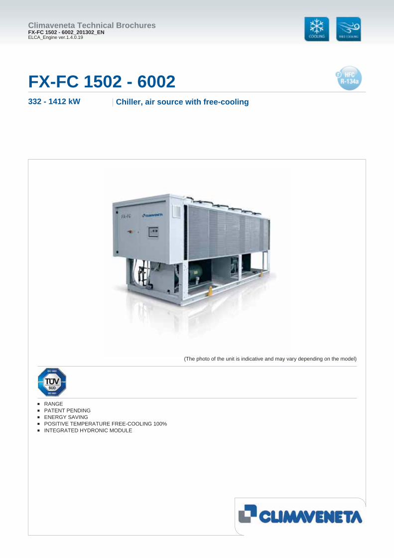
(The photo of the unit is indicative and may vary depending on the model)
RANGEPATENT PENDINGENERGY SAVINGPOSITIVE TEMPERATURE FREE-COOLING 100%INTEGRATED HYDRONIC MODULE
Climaveneta Technical BrochuresFX-FC 1502 - 6002_201302_ENELCA_Engine ver.1.4.0.19
FX-FC 1502 - 6002Chiller, air source with free-cooling332 - 1412 kW

2 FX-FC_1502_6002_201302_EN
FX-FC
HFC R134a
SUMMARY FX-FC1502 - 6002
1. FREE-COOLING system represent1.2 Summer Season1.3 Mid-Season 1.4 Winter Season 1.5 The advantage of FX-FC: elevated energy effi ciency in all operating modes1.6 Why use the free-cooling system? 1.7 Maximum capacity of adaptation1.8 NoGlycol model
2. Product presentation 2.2 Range2.3 Patent pending2.4 Energy saving 2.5 Positive temperature free-cooling 100%2.6 Integrated hydronic module
3. Unit description 3.1 Standard unit composition 3.2 Certifi cations 3.3 Unit’s test 3.4 Electronic control W3000SE Large 3.5 Versions 3.6 Functions 3.7 Accessories 3.8 Group regulation device MANAGER 3000 3.9 Supervisory device FWS 3000 3.10 Energy metering device DEMETRA
4. Technical data 4.1 General technical data
5. Operation limits 6. Hydraulic data
6.1 Water fl ow and pressure drop 7. Electrical data 8. Full load sound level 9. Dimensional drawings 9.1 Legend of pipe connections
pg. n° 3pg. n° 3pg. n° 3 pg. n° 4pg. n° 4pg. n° 5pg. n° 6pg. n° 6 pg. n° 7pg. n° 7 pg. n° 7pg. n° 7pg. n° 7pg. n° 7pg. n° 8pg. n° 8pg. n° 9pg. n° 9pg. n° 9pg. n° 10pg. n° 10pg. n° 11pg. n° 13pg. n° 13pg. n° 14pg. n° 15pg. n° 15pg. n° 23pg. n° 25pg. n° 25pg. n° 27pg. n° 31pg. n° 35pg. n° 37
Liability disclaimerThis bulletin is not exhaustive about: installation, use, safety precautions, handling and transport. Refer to the “General Manual of Installation” for further information.This bulletin refers to standard executions, particularly as re-gards dimensions, weight, electric, hydraulic, aeraulic and re-frigerant connections (where applicable). Contact Climaveneta Commercial Offi ce for further drawings and schemes.
Climaveneta declines any liability deriving from use of the bul-letin.This bulletin is the exclusive property of Climaveneta and all forms of copy are prohibited.The data contained herein are subject to change without no-tice.
Company quality system certifi ed to UNI EN ISO 9001
and environmental certifi cation UNI EN ISO 14001
3 FX-FC_1502_6002_201302_EN
FX-FC
HFC R134a
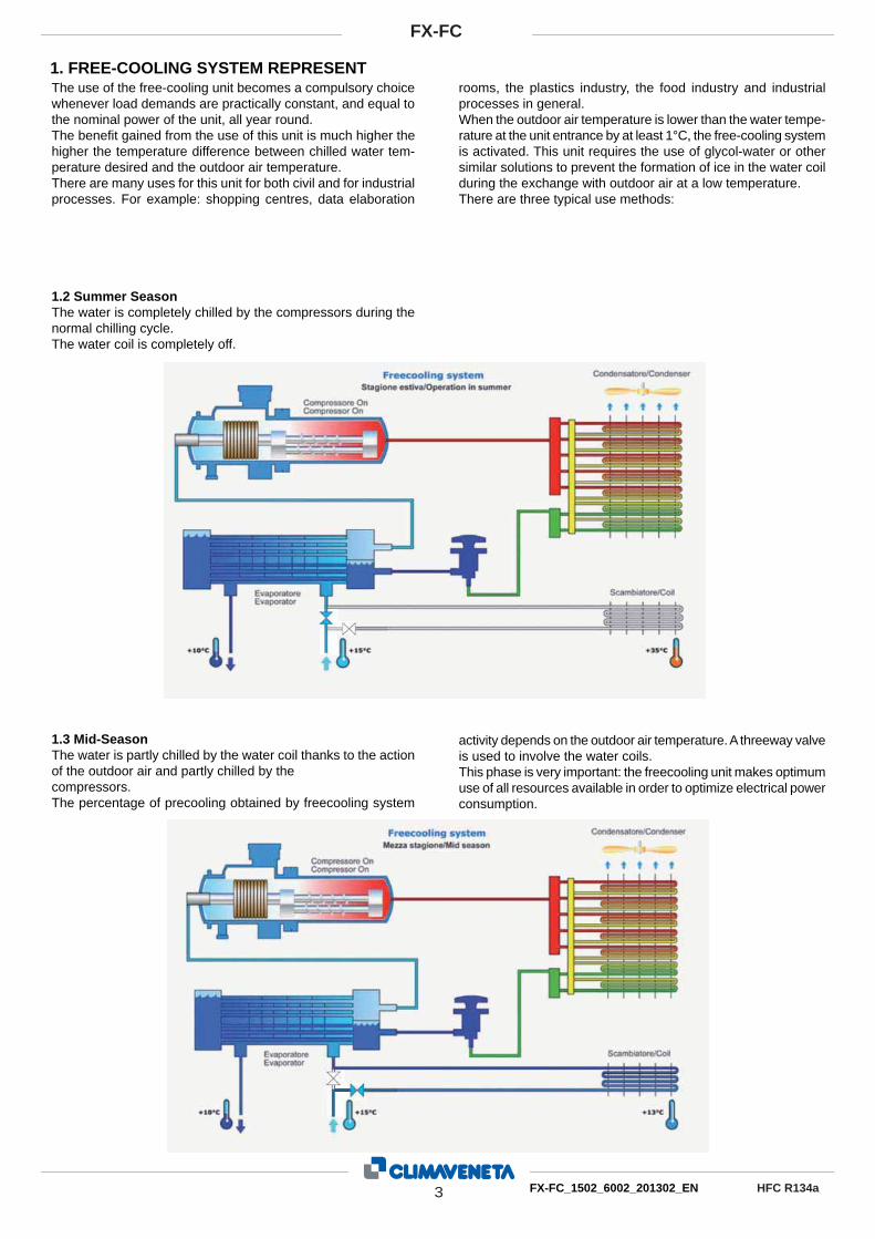
1. FREE-COOLING SYSTEM REPRESENTThe use of the free-cooling unit becomes a compulsory choice whenever load demands are practically constant, and equal to the nominal power of the unit, all year round. The benefi t gained from the use of this unit is much higher the higher the temperature difference between chilled water tem-perature desired and the outdoor air temperature. There are many uses for this unit for both civil and for industrial processes. For example: shopping centres, data elaboration
rooms, the plastics industry, the food industry and industrial processes in general.When the outdoor air temperature is lower than the water tempe-rature at the unit entrance by at least 1°C, the free-cooling system is activated. This unit requires the use of glycol-water or other similar solutions to prevent the formation of ice in the water coil during the exchange with outdoor air at a low temperature.There are three typical use methods:
1.2 Summer SeasonThe water is completely chilled by the compressors during the normal chilling cycle. The water coil is completely off.
1.3 Mid-Season The water is partly chilled by the water coil thanks to the action of the outdoor air and partly chilled by thecompressors.The percentage of precooling obtained by freecooling system
activity depends on the outdoor air temperature. A threeway valve is used to involve the water coils. This phase is very important: the freecooling unit makes optimum use of all resources available in order to optimize electrical power consumption.

4 FX-FC_1502_6002_201302_EN
FX-FC
HFC R134a
Winter SeasonThe generously sized free-cooling exchange surfaces already achieves total free-cooling at positive external air temperatures: the entire FX-FC range is available in the T+ confi guration, 100% positive free-cooling temperature and equal to 2°C for the stan-dard version. (CC @15/10°C, EG30%, Taria 35°C)This design choice increases the number of annual unit ope-rating hours in the full free-cooling mode, thus assuring higher energy saving.
The result of these innovations, some of which are patented, is an FX-FC range that is positioned as an elevated energy-saving product, in both the standard T+ version and the super low noise SL-T+ version.The FX-FC series offers an average saving of 35% compared with the energy used by similar last-generation chillers.
1.5 The advantage of FX-FC: elevated energy effi ciency in all operating modes Thanks to their advanced design and the innovative patent-pending solutions, the FX-FC chillers with free-cooling optimise effi ciency in each of the three operating modes:
Summer SeasonThe innovative BOOSTER, a patented device, increases the effi ciency of the unit in the chiller mode, thus guaranteeing unprecedented EER values (@15/10°C, EG30%, Taria 35°C, EER=3.2).
Mid Season• the activation of free-cooling at an external temperature of
1°C lower than the temperature of the system return water • the cooling setpoint variation management• the ventilation control logic combined with independent con-
densation circuit ventilation help maximise the effect of direct free-cooling.
1.4 Winter Season The water is chilled only by the water coil because the outdoor air temperature is already low enough. In this type of chilling, the only power consumed is for the fans.

5 FX-FC_1502_6002_201302_EN
FX-FC
HFC R134a
1.6 Why use the free-cooling system?We compared the performance of a FOCS2-K unit with a FX-FC/T+ unit in 4 different European cities. The units being compared were both used under the following conditions: Evaporator water temperature 15/10°C, with 30%
ethylene glycol solution. The latitude, type of climate, tempera-ture distribution in hours/year determine the advantages of the freecooling unit and the percentage of energy saved.
26%Ankara
30%London
45%Stockholm
36%Warsaw
FX-FC
Stockholm
FOCS2
45%saving
40.000
35.000
30.000
25.000
20.000
15.000
10.000
5.000
0 %
Ene
rgia
impi
egat
a - T
otal
abs
orbe
d en
ergy
[kW
h]
- 1 5 - 1 0 - 5 0 5 1 0 1 5 2 0 2 5 3 0 3 5 4 0Temperatura aria esterna - Air temperature [°C]
LondonFOCS2
50.000
45.000
40.000
35.000
30.000
25.000
20.000
15.000
10.000
5.000
0 %Ene
rgia
impi
egat
a - T
otal
abs
orbe
d en
ergy
[kW
h]
- 1 5 - 1 0 - 5 0 5 1 0 1 5 2 0 2 5 3 0 3 5 4 0Temperatura aria esterna - Air temperature [°C]
30%saving
FX-FC
FX-FC
Warsaw
FOCS2
36%saving
40.000
35.000
30.000
25.000
20.000
15.000
10.000
5.000
0 %Ene
rgia
impi
egat
a - T
otal
abs
orbe
d en
ergy
[kW
h]
- 1 5 - 1 0 - 5 0 5 1 0 1 5 2 0 2 5 3 0 3 5 4 0Temperatura aria esterna - Air temperature [°C]
FX-FC
Ankara
FOCS2
26%saving
40.000
35.000
30.000
25.000
20.000
15.000
10.000
5.000
0 %Ene
rgia
impi
egat
a - T
otal
abs
orbe
d en
ergy
[kW
h]
- 1 5 - 1 0 - 5 0 5 1 0 1 5 2 0 2 5 3 0 3 5 4 0Temperatura aria esterna - Air temperature [°C]

6 FX-FC_1502_6002_201302_EN
FX-FC
HFC R134a
1.7 Maximum capacity of adaptationThe adjustments that can be activated for all the FX-FC units can support the various applications.They set out to improve load adaptability, reduce the number of on and off sequences and maintain a constant evaporator outlet temperature.
AdjustmentsThe unit leaves the factory set to outlet modulating adjustment with PID (derivative integral proportional) logic on the evaporator outlet temperature; these adjustments, combined with continuous compressor adjustment (minimum compressor separation ope-ration 50%), maintain the outlet water temperature stable and reduce the number of compressor on/off sequences.Traditional inlet step adjustment, however, can always be selec-ted from the parameter.
The capacity of adaptation is also the outcome of attentive compressor management combined with precise free-cooling valve activation logic.
Modulating free-cooling valve optionThe modulating free-cooling valves (optional) on the water side offer improved outlet temperature control also at low external air temperatures.When the unit works entirely in the free-cooling mode with very low external temperatures, it is important to guarantee the requi-red temperature of the chilled water. This is achieved by suitable mixing which is performed by appropriate modulating valves.
EC fan optionThe EC (Electronically Commutated) fans feature motor effi -ciency levels in excess of 90% (EFF-1 classifi cation according to European regulation CEMEP/EU).The elevated effi ciency assured by the DC brushless motor further increases unit performance in all operating modes: De-pending on the ambient air temperature, the increase in EER generated by the EC fans can range from a few percent up to as much as 40%.
Further advantages of the EC fans are the low starting currents and the low noise emissions.
1.8 NoGlycol modelFX-FC in the NoGlycol confi guration is a unit that is suitable for all applications where ethylene glycol or other anti-freeze mixtures cannot be used in the system.Thanks to an intermediate hydraulic circuit, integrated inside
the unit, the hydraulic circuit can be isolated from the system, loaded with water, from the Free Cooling circuit which uses glycol solutions to prevent ice from forming in the external coil.Apart from this, the unit has the same characteristics as those described above.
7 FX-FC_1502_6002_201302_EN
FX-FC
HFC R134a
Outdoor unit for the production of chilled water with semi-hermetic screw compressors optimized for R134a, axial-fl ow fans, condensing coil with copper tubes and aluminium fi ns, shell and tube evaporator design by Climaveneta and electronic expansion valve. High effi ciency chiller operation guaranteed by a patented-pending booster solution.
2.2 RangeExtended capacity range.
2.3 Patent pending Booster function to increase chiller effi ciency.
2.4 Energy savingEnergy saving guaranteed by free-cooling, which exploits the low external air temperatures; free-cooling control with optional modulating valve.
2.5 Positive temperature free-cooling 100%Big heat exchangers surfaces: 100% free-cooling cooling load satisfi ed at positive environment temperature.
2.6 Integrated hydronic moduleIt consists of 2 pumps, 2 or 4-pole motor, fi xed or variable spe-ed, with high or low head options to satisfy different industrial applications and demands for comfort.
2. PRODUCT PRESENTATION

8 FX-FC_1502_6002_201302_EN
FX-FC
HFC R134a
Chiller, air source with free-cooling Outdoor unit for the production of chilled water with semi-her-metic screw compressors optimized for R134a, axial-fl ow fans, condensing coil with copper tubes and aluminium fi ns, shell and tube evaporator and electronic expansion valve. Chiller charac-terized by high effi ciency ensured by booster patent pending solution.Base and supporting structure and panels are of galvanized epoxy powder coated steel with increased thickness.
Installation noteThe unit is supplied fully refrigerant charged and factory tested. On site installation only requires power and hydraulic connec-tion.
3.1 Composizione unita’ standardStructureBase and frame in galvanized steel. The supporting frame are polyester-painted for the highest resitance to external factors: surfaces´ hue and brightness are preserved. In silenced ver-sions compressors´ box is covered with an acoustic layer to reduce global noise emissions.
Refrigerant circuit Unit designed with dedicated and independent refrigerant cir-cuits in order to ensure continuous operation, limited pollution, and easy maintenance. In addition to main components descri-bed in the following sections, each refrigerant circuit is fi tted as standard with:- electronic thermostatic valve- high and low pressure safety valve with visualization of the
pressure´s level directly from the controller´s interface - liquid line shut-off valve - compressor’s discharge valve - drier fi lter with replaceable cartridge - refrigerant line sight glass with humidity indicator - high pressure transducer - high and low pressure transducers- non -return valve in compressor´s discharge line integrated in
the compressor - liquid line shut-off valve - BOOSTER patent pending
Water circuitFree Cooling “FC”- two way-valve ON-OFF- water-air heat exchanger
Water circuit NGFree Cooling “FC NG”The internal water circuit, fi lled with a 30% ethylene glycol solu-tion and linked to the water-air exchangers, is made up of:- circulation pump- intermediate plate heat exchanger- antifreeze electric heater for plate heat exchanger- pump shut off valves- makeup tap- Inlet valve- pressure gauge- expansion tank.
Heaters and thermal insulance on the hydraulic circuit:
CompressorsNew semi-hermetic screw compressors designed for high effi -ciency both at full and partial load.Semi-hermetic screw compressors with 2 fi ve- and six-lobe ro-tors: the fi ve-lobe rotor is splined directly onto the motor (nomi-nal speed 2950 rpm) without the use of interposed gears. The bearings provided along the rotor axis in a separate cham-ber isolated from the compression chamber are made in carbon steel.Each compressor is provided with an inlet for refrigerant injec-tion (for the extension of operating limits) and the use of the economizer (for the output capacity and effi ciency´s increase). Optimized lubrication guarantees oil´s distribution between me-chanical parts, without using an oil pump; the built-in oil sepa-rator has 3 stages of separation, and a 10 mm stainless steel mesh fi lter ensures the constant presence of oil inside. Cooling power is partialized by a slide valve, which depen-ding on the position assumed, permits a stepless compression chamber reduction; each compressor can therefore smoothly partialize from 25% to 100% of its capacity. The two pole motors are fi tted as standard with electric devices to limit the absorbed current during compressor start-up, and with empty start-up. Each compressor is fi tted with manual-reset motor thermal pro-tection, delivery gas temperature and oil level controls and an electric resistance for the carter´s heating while the compressor is stopped. A check valve fi tted on the refrigerant delivery line prevents the rotors from reversing after stopping. On-off cocks on the delivery line of each compressor to isolate the refrigerant charge in the heat exchanger when required.
Compressors part-winding start for sizes up1502 to 2002, and star-delta for all other sizes.
Plant side heat exchanger Direct expansion shell and tube exchanger, with evaporator function, with coolant on tube side and water on shell side. The single-step tube nest provides an almost perfect counter-cur-rent exchange with the heat transfer fl uid. Shell side fi tted with baffl es to increase turbulence and therefore improve exchange effi ciency. Steel shell covered in a condensation-proof lining in closed-cell foamed elastomer with a thickness of 10 mm and a thermal conductivity of 0.033 W/mK at 0°C (in the NG version,
3. UNIT DESCRIPTION
Electric heaters (Tair > -15°C)
Thermal insulance (Tair > -15°C)
STDFC FC NG STD
FC FC NG
Evaporator NO YES YES YES(double layer)
Pipes NO YES YES YES(double layer)
Pumps(if present) NO YES YES YES
(double layer)
NGexchanger - YES - YES
(double layer)
NG pumps - NO - YES
NG pipes - NO - YES
Booster NO NO NO NO

9 FX-FC_1502_6002_201302_EN
FX-FC
HFC R134a
the lining is 20 mm thick). The tube nest is made from copper tubes with internal and external grooves for favouring heat ex-change and mechanically expanded onto the tube plates.Only for the NG version, the shell and tube exchanger, the in-termediate plate exchanger and the water pipes in the primary circuit (user - intermediate exchanger - evaporator) are fi tted with an antifreeze electric heater in order to prevent ice forming inside when the unit is electrically powered but not running. For both solutions (standard FC and NG FC) with the unit running, protection is assured by a differential pressure switch.
Source side heat exchangerThe fi nned coil exchanger, made from copper tubes and alu-minium fi ns spaced to optimise heat exchange effi ciency, is di-vided into two sections. One is dedicated to condensation and the other to air-cooling the water in the Free Cooling mode. The exchanger is suitably sized to cater for pressure drops whilst assuring the best heat exchange and full free cooling already at positive air temperatures (T+).
Fan section source sideAxial electric fans, system of protection IP54 and “F” insula-tion class, with external rotor, profi led die-cast aluminium bla-des, housed in aeodynamic hoods complete with guard grille. 6-poles electric motor with built-in thermal protection. Variable Speed low-temperature Device (DVV) to control condensation adjusting the rotational speed with voltage steps (auto-transfor-mer) is standard for all versions.
Quadro elettrico di potenza e controlloElectrical and control panel built to EN60204-1 and EC204-1 standards, complete with:- electronic controller - control circuit transformer- general door lock isolator- power circuit with bar distribution system - fuses for compressors - compressors protection with internal thermal overload - terminals for cumulative alarm block - remote ON/OFF terminals- spring-type control circuit terminal board - phases sequence control - relays for voltage monitoring
Power input 400V/3/50HzCompressors part-winding start for sizes up1502 to 2002, and star-delta for all other sizes.
3.2 Certifi cation, reference standardThe unit complies with the following directives and relative amendments:- CE - Declaration of conformity certifi cate for the European
Union- GOST - Product quality certifi cate for Russian Federation - SAFETY QUALITY LICENCE - Product quality certifi cate for
Popular Republic of China- M&I - Product quality certifi cate for Australia and New Zea-
land- Machine directive 2006/42/EC - PED directive 97/23/EC - Low Voltage directive 2006/95/EC - ElectroMagnetic compatibility directive 2004/108/EC - ISO 9001 - Company´s Quality Management System certifi -
cation- ISO 14001 - Company´s Environmental Management System
certifi cation.
3.3 Tests Tests performed throughout the production process, as indica-ted in ISO9001. Performance or noise tests can be performed by highly quali-fi ed staff in the presence of customers. Performance tests comprise the measurement of: - electrical data - water fl ow rates - working temperatures - power input - power output - pressure drops on the water-side exchanger both at full load (at the conditions of selection and at the most critical conditions for the condenser) and at part load conditions. During performance testing it is also possible to simulate the main alarm states. Noise tests are performed to check noise emissions according to ISO3744.
3.4 W3000SE Large controller The W3000 SE Large controller offers advanced functions and algorithms. The keypad is generously sized with full operating status display. The commands and detailed LCD display make access to the unit’s settings easy and safe. These resources allow to consult and intervene on the unit by means of a mul-ti-level menu, with selectable language setting. It´s available as option the touch screen interface: WVGA 7´´ colour display with LED adjustable back lighting. The touch screen technolo-gy allows an intuitive navigation, ensure a safety data access through 3 different password levels and permits to visualize in diagrams some monitored quantities trend. The diagnostics includes a complete alarm management, with the “black-box” and alarm logging functions for enhanced analysis of the unit operation. For multiple units’ systems, the regulation of the re-sources, via optional proprietary devices, can be implemented. Energy metering, for both consumption and capacity, can also be developed. Supervision can be easily developed via pro-prietary devices or the integration in third party systems by me-ans of the most common protocols as ModBus, Bacnet, Bac-net-over-IP, Echelon LonWorks. Compatibility with the remote keyboard managing up to 10 units. Availability of an internal real time clock for operation scheduling (4-day profi les with 10 hour belts). The regulation features the continuous modulation of capacity, based on a dynamic dead band and referring to the leaving water temperature. As alternative, step-wise regulation is also available, referred to the return water temperature with selectable proportional- or proportional-integral logic. As option (VPF package), the modulation of capacity is integrated with the modulation of the water fl ow, by means of inverter and de-dicated resources for the hydraulic circuit

10 FX-FC_1502_6002_201302_EN
FX-FC
HFC R134a
3.5 Version /T+Version with positive free-cooling temperature 100%High effi ciency thanks to the patent-pending booster, maximum free-cooling already at positive air temperatures.
/SL-T+Super low noise version with positive free-cooling tempe-rature 100%High effi ciency thanks to the patent-pending booster, maximum free-cooling already at positive air temperatures and super low noise version.This confi guration features special soundproofi ng for the com-pressor chamber and pumps (if present), reduced fan speed and an oversized condensing section.However, fan speed automatically increases in particularly tou-gh environmental conditions.
3.6 Confi gurations < >, Standard unit Standard FreeCooling unit for water and glycol systems.
NG, No glycol unit This unit does not require any antifreeze solutions on the chilled water circuit thanks to an intermediate plate exchanger betwe-en the evaporator and the water-water exchanger. The water circulating between the intermediate plate exchanger and the water-air exchanger will contain glycol, while the water betwe-en the user and the evaporator will not contain an antifreeze solution.

11 FX-FC_1502_6002_201302_EN
FX-FC
HFC R134a
3.7 Accessories
COD. ACCESSORIES DESCRIPTION BENEFIT881 Cu/Cu condensing coils Air-refrigerant heat exchanger with copper fi ns and
tubes.Recommended for applications in corrosive atmo-spheres.
894 Condensing coils with epoxy-coated fi ns Painted air-refrigerant heat exchanger. Recommended for applications in medium level pollution atmospheres.
895 Condensing coils with Fin Guard Silver treat-ment
Air-refrigerant heat exchanger with epoxidic treat-ment on coils and fi ns.
Recommended for marine exposure conditions, with an high level of pollution or other aggressive atmospheres.
2001 Coil protection grill in peraluman Protects against the intrusion of solid bodies with mediumlarge dimensions.
2021 Anti-intrusions grills Anti-intrusions grills. Avoid the intrusion of solid bodies into the unit's structure.
1511 Soft start Electronic device adopted to manage the inrush current.
Break down of the inrush current as soon as the electrical motor is switch on, lower motor's mechani-cal wear, favourable sizing for the electrical system.
1955 kit HT (*) Kit to increase the unit's operating range. Full load operation is guaranteed up to 50°C outdoor temperature. Beyond this limit, up to 57°C, the unit is suitable to provide cooling capacity at partial load; in this case electrical panel has to be cooled (refer to sales department for quotation). The accessory is required for installation in extremely hot areas.
808 EC fans (*) Electronically commutated fans (EC fans); the brushless motor, governed by a special controller, continuously adjust fans' speed.
Reduced energy consumption, electromagnetic noises and current's absorption even during start-up phase. Noise reduces proportionally to unit's partialization.
4181 ModBUS connectivity Interface module for ModBUS protocols. Allows integration with BMS operating with ModBUS protocol.
4184 BACnet connectivity Interface module for BACnet protocols. Allows integration with BMS operating with BACnet protocol.
4182 Echelon connectivity Interface module for Echelon systems. Allows integration with BMS operating with LonWor-ks procotls.
4185 BACnet OVER IP connectivity Interface module for BACnet OVER-IP protocols. Allows to interconnect BACnet devices over InternetProtocol within wide-area networks.
6161 AUXILIARY SIGNAL 4-20mA 4..20mA analogue input. Allows to change the operating set-point according to the value of current applied to the analogue input.
Enforce Energy Saving policies
6162 REMOTE SIGNAL DOUBLE SP Allows to activate the Energy Saving set-point Enforce Energy Saving policy
3601 Compressors' on/off signal Auxiliary contacts providing a voltage-free signal Allows remote signalling of compressor's activationor remote control of any auxiliary loads.
6195 W3000 TOUCH SCREEN Colour WVGA 7'' display keyboard with adjustable LED backlight (WARNING: with outdoor temperatu-re below 0°C the display responce time may visibly increase).
The touch-screen's technology is characterized by an easy-to-access data, and it allows an effective graphical representation of the main fi gures protec-ting the access through 3 privilege levels.
3411 Automatic circuit breakerson compressors Over-current switch on the major electrical loads. It protects compressors from possible current peaks.
3412 Automatic circuit breakers Over-current switch on the major electrical loads. It protects compressors and/or fans from possiblecurrent peaks.
6171 INPUT REMOTE DEMAND LIMIT Digital input (voltage free). It permits to limit the unit's power absorption for safety reasons or in temporary situation.
3391 Electric heater on board Electrical resistance fed directly from the unit, is automatically activated at temperatures internal QE below 30 ° C (off state at T higher than 40 ° C).
It avoids the risk of humidity condensation on the electrical panel.
2301 Compressors' acoustic enclosure Enclosure realized with peraluman panels lined with an acoustic insulation made by polyester fi ber of thickness 30 mm.
A sound power level reduction of 2 dB(A) is achie-ved.
2315 Noise reducer Electrical transformer to manage the fan's speed according to the specifi c condensing pressure + compressors' acoustical enclosure.
The dedicated fans' speed calibration together with the soundproofi ng of the most critical components permit a noise reduction of 5/6 dB(A) (the precise unit's performance when NOISE REDUCER option is present have to be checked with the selection software).
1901 COMPRESSOR SUCTION VALVE Shut-off solenoid valve on compressor's suction circuit.
Simplifi es maintenance activities.
3301 Power factor correction Condensators on the compressors' power inlet line. The unit’s average cos(phi) increases from an ave-rage value of 0,87 to a value (average) of 0,92.
1961 PRESSURE RELIEF VALVES Dual relief valve with switch. Allows to unselect a relief valve in order to service the unit avoiding medium or long inoperative periods.

12 FX-FC_1502_6002_201302_EN
FX-FC
HFC R134a
COD. ACCESSORIES DESCRIPTION BENEFIT1221 Modulating Valve 2 way modulating valve for the control of the water
temperatureEnsure the control of the leaving water temperature when the outdoor temperaure is very low. The use of this option is mandatory when the differenco between the leaving water temperature and the outdoor temperature is higher than 15°K
1801 Evaporator fl owswitch (water side)
2911 Flanged heat exchangers connection
3183 + 3184
Hydronic group (See dedicate section)
3360 Relay for pump(s) managment Relay for the pump(s) on/off. It permits the pumps on/off. In case of 2 pumps, one in stand-by to the other, it's possible to balance the operating hours between them.
DEMETRA (see dedicated manual) Software to monitor capacity and energy absorbed by the units.
Allows a dynamic monitoring of the installed units and therefore a data (hourly based) downloading to support the current needs of energy management.
5921 Network analyzer per DEMETRA Tools to measure the electricity absorbed by the unit.
They meter the electricity absorbed and are connec-ted with RS485 bus to an external device for energy metering (DEMETRA - see dedicated manual).
Group regulation device (See dedicate section)
Supervisory device (See dedicate section)
381 Numbered cables on electrical board
382 Coloured cables on electrical board for UK market
383 Numbered cables and coloured cables on electrical board for UK market
2101 Rubber anti vibration device
2102 Spring anti vibration device
9965 Coil s protection grill and nylon coverage
9979 Container packing
1971 REINFORCING BARS Bars used to reinforce the structure. Improve resistance during long transportation.
(*) : EC fans (808) are not compatible with the accessory kit HT (1955).

13 FX-FC_1502_6002_201302_EN
FX-FC
HFC R134a
3.8 Group regulation device MANAGER 3000
Manager3000 allows the regulation within a group of hydronic units. The controller features high-level algorithms and user interface. The controller is suitable for the management of 2- or 4-pipe systems, with regulation on one water circuit, for chiller- or heat pump units and relevant mode change-over, and also with regulation on two circuits, with independent set-points and parameters, thus exploiting the simultaneous supply of chilled- and hot water. The controller manages up to 8 units, with activation logic focused at the balancing of operation times and at the achievement of the highest energy effi ciency. It is possible to defi ne condi-tions of dynamic stand-by and priority as regards the units’ activation. It is also feasible the rotation among the system’s units, also in cases of constant load. The alarm management is featured, with plain text descriptions and possible notifi cation to remote recipients. Two relay outputs are available, associated to unit- and device alarms. The user interface allows a safe and easy use, thanks to its touch-screen display, back-lit 8.4” type. The multi-level menu features the language selection and diffe-rentiated access profi les(user and maintenance).The circuit tem-peratures and the status of both system- and unit- operation are displayed, via one overview page plus detailed pages. The regu-lation can be based on proportional- or proportional+integral lo-gics, or also on a dead-band algorithm with dynamic adjustment,
3.9 Supervisory device FWS 3000
Supervisory device for a system composed of Climaveneta units.Supervision can be operated via any computer, with direct- or LAN-based connection. It is therefore achieved the internet-based management of the resources, thanks to the built-in web-server and to the availability of web pages specifi cally defi ned both for the overall system monitoring and the access to detailed information about each unit. The supervision achieved by this way does not require the installation of any additional software on the com-puter and utilizes the most common browsers. This allows the use of any computer connected to the network or web. A RS-485 serial connection is available for the communication with the slave devices, up to 15 con-nected units. FWS3000 is particularly effective for the supervision of systems composed of packaged or WET units. The access to the supervision is easy and safe, thanks to the use of password. It is possible to visualize a complete list of
with relevant temperature inputs managed by the device. Features as set-point offset, also referred to the outdoor tem-perature, and demand limit are included, with relevant analog inputs.The device is integrated in the best way with the units, preventing
simultaneous activations or resources and optimizing effi ciency, overall inrush current values and also operation of water pumps possibly associated to the units. The WebManager option allows the access to the device and its settings, via any computer, with direct- or LAN-based connection, therefore also via internet resources; this is associated to the availability of historical charts for the main operating variables. The “Variable Primary Flow” option represents a unique regulation dedica-ted to hydronic systems with variable water fl ow. This represents a crucial contribution to the reduction of the costs related to the hydraulic plant and its operation.It is available as option the interface
with the Demetra metering device: thus it is possible to acquire and log the values of the system units’ electric consumption, together with their operating status; this allows therefore to analyze the system’s operating performances throughout time, in terms of both absorbed energy and cooling / heating capaci-ties, consistently with the implementation of enhanced energy management policies for the building.
unit operational variables: temperatures, humidity, indoor air quality, status of the unit. This is associated to the availability
of historical charts for the main ope-rating variables. It is also available the display of alarms, with plain text descriptions and possible notifi cation to remote recipient. The setting of the main operational parameters, for each unit, is also allowed: unit status, mode, set-point, time scheduling (based on 4 days, 10 time belts per day). Various levels of customization are offered, for both the web pages and connectivity-related functions.It is available as option the interface with the Demetra metering device: thus it is possible to acquire and log the values of the system units’ electric consumption, together with their ope-rating status; this allows therefore to analyze the system’s operating perfor-
mances throughout time, in terms of both absorbed energy and cooling / heating capacities, consistently with the implementation of enhanced energy management policies for the building.
14 FX-FC_1502_6002_201302_EN
FX-FC
HFC R134a
3.10 Energy metering deviceDEMETRA
DEMETRA represents the solution for the most evolved and up-to-date requirements concerning the energy management of HVAC hydraulic systems. DEMETRA (DEvice for Metering of Energy TRAnsfers) in fact, enables the metering of both electric energy consumption and cooling performances; thanks to the intimate connection to each Climaveneta units controlling alghoritms, with DEMETRA the fi nal user can even measure the freecooling quote, get for free with the direct air/water heat exchanger. DEMETRA can monitor up to 8 units connected together. DEMETRA continuously acquires the electric energy consum-ption, the primary circuit and outdoor air temperature, and the water fl ow rates on the user side heat exchanger. These values are integrated with the operating status of each unit, as detected by Manager3000 or FWS3000,to calculate the fi nal unit performance. Thanks to the web-based structure of DEMETRA, the fi nal user can, in every moment after authentication, access to the its homepage and visualize or download the data for the relevant variables in a chiller operation.

FX-FC 1502 - 6002_201302_EN HCF R134a15ELCA_Engine ver.1.4.0.19
FX-FC /T+5.1 GENERAL TECHNICAL DATA
APPLICATION STANDARDFX-FC /T+ 1502 1702 1902 2002 2202 2602 2702 3002 3202 3402Power supply V/ph/Hz 400/3/50 400/3/50 400/3/50 400/3/50 400/3/50 400/3/50 400/3/50 400/3/50 400/3/50 400/3/50PERFORMANCEFREE-COOLING OFFCooling capacity (1) kW 335 372 433 481 530 619 665 695 753 826Compressor power input (1) kW 76,9 86,6 98,6 113 121 148 161 175 183 192Total power input (1) kW 88,9 103 115 133 141 172 185 199 211 224EER (1) 3,77 3,63 3,77 3,62 3,77 3,59 3,60 3,49 3,57 3,69Free Cooling (Tae = 10,0°C)Power (1) kW 108 122 141 156 173 205 218 223 248 266% Free cooling (1) % 32 33 33 32 33 33 33 32 33 32FREE-COOLING ON 100%Cooling capacity (2) kW 335 372 433 481 530 619 665 695 753 826Total power input (2) kW 12,0 16,0 16,0 20,0 20,0 24,0 24,0 24,0 28,0 32,0EER (2) 28,0 23,3 27,0 24,0 26,5 25,8 27,7 29,0 26,9 25,8Total FC temperature (2) °C 1,2 1,4 1,4 1,4 1,5 1,8 1,8 1,4 1,8 1,2EXCHANGERSHEAT EXCHANGER USER SIDE IN REFRIGERATIONGlycol (1) % 30 30 30 30 30 30 30 30 30 30Water flow (1) m³/h 64,0 71,0 82,5 91,7 101 118 127 133 144 158Pressure drop (1) kPa 68,7 84,7 78,3 86,3 63,2 77,5 65,2 71,1 62,4 75,1COMPRESSORSCompressors nr. N° 2 2 2 2 2 2 2 2 2 2Number of capacity N° 0 0 0 0 0 0 0 0 0 0No. Circuits N° 2 2 2 2 2 2 2 2 2 2Regulation STEPLESS STEPLESS STEPLESS STEPLESS STEPLESS STEPLESS STEPLESS STEPLESS STEPLESS STEPLESS
Min. capacity step % 25 25 25 25 25 25 25 25 25 25Refrigerant R134a R134a R134a R134a R134a R134a R134a R134a R134a R134aRefrigerant charge kg 85,0 90,0 108 119 128 141 145 175 180 190Oil charge kg 30,0 30,0 30,0 30,0 44,0 44,0 38,0 38,0 38,0 49,0FANSQuantity N° 6 8 8 10 10 12 12 12 14 16Air flow m³/s 35,9 43,3 47,5 54,9 58,8 64,3 67,4 67,4 77,2 90,8Fans power kW 2,00 2,00 2,00 2,00 2,00 2,00 2,00 2,00 2,00 2,00NOISE LEVELNoise Pressure (3) dB(A) 67 68 68 68 69 70 69 69 69 69Noise Power (4) dB(A) 99 100 100 100 101 102 102 102 102 102SIZE AND WEIGHTA (5) mm 4000 4000 4900 4900 5800 5800 6400 6400 7000 7900B (5) mm 2260 2260 2260 2260 2260 2260 2260 2260 2260 2260H (5) mm 2500 2500 2500 2500 2500 2500 2500 2500 2500 2500Operating weight (5) kg 4880 4990 5520 5700 7000 7410 8270 8310 8750 9600
Notes:1 Plant (side) cooling exchanger water (in/out) 15°C/10°C; Source (side) heat exchanger air (in) 30°C; Ethylene glycol 30% (not applicabile to NG configuration)2 Plant (side) cooling exchanger water (in/out) 15°C/10°C; Ethylene glycol 30% (not applicabile to NG configuration)3 Average sound pressure level, at 10m distance, unit in a free field on a reflective surface; non-binding value obtained from the sound power level.4 Sound power on the basis of measurements made in compliance with ISO 9614 and Eurovent 8/1 for Eurovent certified units; in compliance with ISO 3744 for non-certified units.5 Unit in standard configuration/execution, without optional accessories.- Unavailable
FX-FC 1502 - 6002_201302_EN HCF R134a16ELCA_Engine ver.1.4.0.19
FX-FC /T+GENERAL TECHNICAL DATA
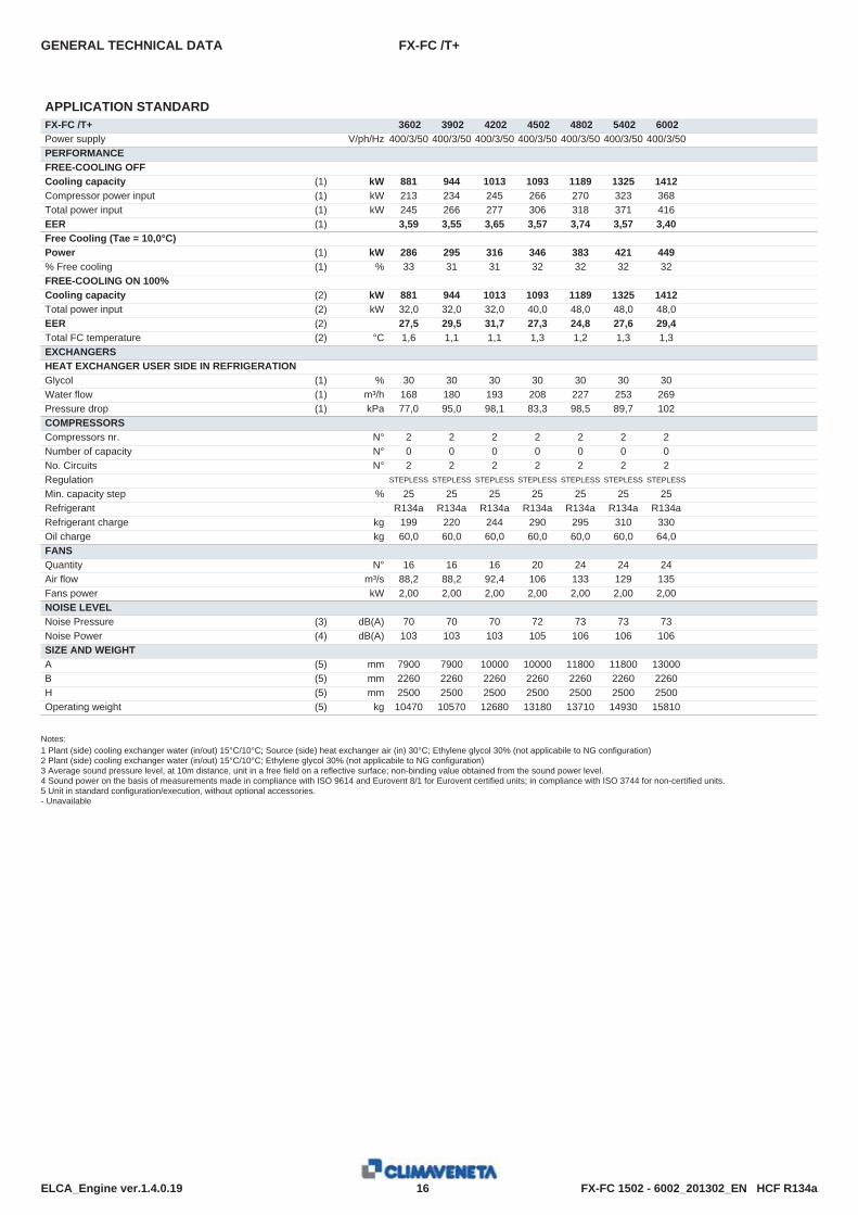
APPLICATION STANDARDFX-FC /T+ 3602 3902 4202 4502 4802 5402 6002Power supply V/ph/Hz 400/3/50 400/3/50 400/3/50 400/3/50 400/3/50 400/3/50 400/3/50PERFORMANCEFREE-COOLING OFFCooling capacity (1) kW 881 944 1013 1093 1189 1325 1412Compressor power input (1) kW 213 234 245 266 270 323 368Total power input (1) kW 245 266 277 306 318 371 416EER (1) 3,59 3,55 3,65 3,57 3,74 3,57 3,40Free Cooling (Tae = 10,0°C)Power (1) kW 286 295 316 346 383 421 449% Free cooling (1) % 33 31 31 32 32 32 32FREE-COOLING ON 100%Cooling capacity (2) kW 881 944 1013 1093 1189 1325 1412Total power input (2) kW 32,0 32,0 32,0 40,0 48,0 48,0 48,0EER (2) 27,5 29,5 31,7 27,3 24,8 27,6 29,4Total FC temperature (2) °C 1,6 1,1 1,1 1,3 1,2 1,3 1,3EXCHANGERSHEAT EXCHANGER USER SIDE IN REFRIGERATIONGlycol (1) % 30 30 30 30 30 30 30Water flow (1) m³/h 168 180 193 208 227 253 269Pressure drop (1) kPa 77,0 95,0 98,1 83,3 98,5 89,7 102COMPRESSORSCompressors nr. N° 2 2 2 2 2 2 2Number of capacity N° 0 0 0 0 0 0 0No. Circuits N° 2 2 2 2 2 2 2Regulation STEPLESS STEPLESS STEPLESS STEPLESS STEPLESS STEPLESS STEPLESS
Min. capacity step % 25 25 25 25 25 25 25Refrigerant R134a R134a R134a R134a R134a R134a R134aRefrigerant charge kg 199 220 244 290 295 310 330Oil charge kg 60,0 60,0 60,0 60,0 60,0 60,0 64,0FANSQuantity N° 16 16 16 20 24 24 24Air flow m³/s 88,2 88,2 92,4 106 133 129 135Fans power kW 2,00 2,00 2,00 2,00 2,00 2,00 2,00NOISE LEVELNoise Pressure (3) dB(A) 70 70 70 72 73 73 73Noise Power (4) dB(A) 103 103 103 105 106 106 106SIZE AND WEIGHTA (5) mm 7900 7900 10000 10000 11800 11800 13000B (5) mm 2260 2260 2260 2260 2260 2260 2260H (5) mm 2500 2500 2500 2500 2500 2500 2500Operating weight (5) kg 10470 10570 12680 13180 13710 14930 15810
Notes:1 Plant (side) cooling exchanger water (in/out) 15°C/10°C; Source (side) heat exchanger air (in) 30°C; Ethylene glycol 30% (not applicabile to NG configuration)2 Plant (side) cooling exchanger water (in/out) 15°C/10°C; Ethylene glycol 30% (not applicabile to NG configuration)3 Average sound pressure level, at 10m distance, unit in a free field on a reflective surface; non-binding value obtained from the sound power level.4 Sound power on the basis of measurements made in compliance with ISO 9614 and Eurovent 8/1 for Eurovent certified units; in compliance with ISO 3744 for non-certified units.5 Unit in standard configuration/execution, without optional accessories.- Unavailable

FX-FC 1502 - 6002_201302_EN HCF R134a17ELCA_Engine ver.1.4.0.19
FX-FC /NG /T+GENERAL TECHNICAL DATA
APPLICATION NGFX-FC /NG /T+ 1502 1702 1902 2002 2202 2602 2702 3002 3202 3402Power supply V/ph/Hz 400/3/50 400/3/50 400/3/50 400/3/50 400/3/50 400/3/50 400/3/50 400/3/50 400/3/50 400/3/50PERFORMANCEFREE-COOLING OFFCooling capacity (1) kW 345 383 444 494 545 636 683 714 774 849Compressor power input (1) kW 77,5 87,0 99,1 114 122 149 161 176 184 193Total power input (1) kW 89,5 103 115 134 142 173 185 200 212 225EER (1) 3,85 3,71 3,86 3,70 3,85 3,67 3,68 3,57 3,65 3,78Free Cooling (Tae = 10,0°C)Power (1) kW 90,0 102 117 131 145 171 183 186 208 223% Free cooling (1) % 26 27 26 26 27 27 27 26 27 26FREE-COOLING ON 100%Cooling capacity (2) kW 345 383 444 494 545 636 683 714 774 849Total power input (2) kW 12,0 16,0 16,0 20,0 20,0 24,0 24,0 24,0 28,0 32,0EER (2) 28,7 23,9 27,8 24,7 27,2 26,5 28,5 29,7 27,6 26,5Total FC temperature (2) °C -1,9 -1,6 -1,7 -1,7 -1,6 -1,3 -1,3 -1,7 -1,3 -1,9EXCHANGERSHEAT EXCHANGER USER SIDE IN REFRIGERATIONGlycol (1) % 0 0 0 0 0 0 0 0 0 0Water flow (1) m³/h 59,4 65,9 76,5 85,1 93,8 110 118 123 133 146Pressure drop (1) kPa 100 123 113 121 117 118 107 116 123 107COMPRESSORSCompressors nr. N° 2 2 2 2 2 2 2 2 2 2Number of capacity N° 0 0 0 0 0 0 0 0 0 0No. Circuits N° 2 2 2 2 2 2 2 2 2 2Regulation STEPLESS STEPLESS STEPLESS STEPLESS STEPLESS STEPLESS STEPLESS STEPLESS STEPLESS STEPLESS
Min. capacity step % 25 25 25 25 25 25 25 25 25 25Refrigerant R134a R134a R134a R134a R134a R134a R134a R134a R134a R134aRefrigerant charge kg 85,0 90,0 108 119 128 141 145 175 180 190Oil charge kg 30,0 30,0 30,0 30,0 44,0 44,0 38,0 38,0 38,0 49,0FANSQuantity N° 6 8 8 10 10 12 12 12 14 16Air flow m³/s 35,9 43,3 47,5 54,9 58,8 64,3 67,4 67,4 77,2 90,8Fans power kW 2,00 2,00 2,00 2,00 2,00 2,00 2,00 2,00 2,00 2,00NOISE LEVELNoise Pressure (3) dB(A) 67 68 68 68 69 70 69 69 69 69Noise Power (4) dB(A) 99 100 100 100 101 102 102 102 102 102SIZE AND WEIGHTA (5) mm 4000 4000 4900 4900 5800 5800 6400 6400 7000 7900B (5) mm 2260 2260 2260 2260 2260 2260 2260 2260 2260 2260H (5) mm 2500 2500 2500 2500 2500 2500 2500 2500 2500 2500Operating weight (5) kg 5270 5470 6020 6250 7520 8000 9020 9060 9420 10300
Notes:1 Plant (side) cooling exchanger water (in/out) 15°C/10°C; Source (side) heat exchanger air (in) 30°C; Ethylene glycol 0% (not applicabile to NG configuration)2 Plant (side) cooling exchanger water (in/out) 15°C/10°C; Ethylene glycol 0% (not applicabile to NG configuration)3 Average sound pressure level, at 10m distance, unit in a free field on a reflective surface; non-binding value obtained from the sound power level.4 Sound power on the basis of measurements made in compliance with ISO 9614 and Eurovent 8/1 for Eurovent certified units; in compliance with ISO 3744 for non-certified units.5 Unit in standard configuration/execution, without optional accessories.- Unavailable

FX-FC 1502 - 6002_201302_EN HCF R134a18ELCA_Engine ver.1.4.0.19
FX-FC /NG /T+GENERAL TECHNICAL DATA
APPLICATION NGFX-FC /NG /T+ 3602 3902 4202 4502 4802 5402 6002Power supply V/ph/Hz 400/3/50 400/3/50 400/3/50 400/3/50 400/3/50 400/3/50 400/3/50PERFORMANCEFREE-COOLING OFFCooling capacity (1) kW 905 970 1040 1123 1221 1361 1450Compressor power input (1) kW 215 235 247 268 271 325 370Total power input (1) kW 246 267 279 308 319 373 418EER (1) 3,67 3,63 3,73 3,65 3,82 3,65 3,47Free Cooling (Tae = 10,0°C)Power (1) kW 240 247 264 290 321 353 376% Free cooling (1) % 26 26 25 26 26 26 26FREE-COOLING ON 100%Cooling capacity (2) kW 905 970 1040 1123 1221 1361 1450Total power input (2) kW 32,0 32,0 32,0 40,0 48,0 48,0 48,0EER (2) 28,3 30,3 32,5 28,1 25,4 28,4 30,2Total FC temperature (2) °C -1,5 -2,0 -2,0 -1,8 -1,8 -1,7 -1,7EXCHANGERSHEAT EXCHANGER USER SIDE IN REFRIGERATIONGlycol (1) % 0 0 0 0 0 0 0Water flow (1) m³/h 156 167 179 193 210 234 250Pressure drop (1) kPa 114 137 157 131 155 165 187COMPRESSORSCompressors nr. N° 2 2 2 2 2 2 2Number of capacity N° 0 0 0 0 0 0 0No. Circuits N° 2 2 2 2 2 2 2Regulation STEPLESS STEPLESS STEPLESS STEPLESS STEPLESS STEPLESS STEPLESS
Min. capacity step % 25 25 25 25 25 25 25Refrigerant R134a R134a R134a R134a R134a R134a R134aRefrigerant charge kg 199 220 244 290 295 310 330Oil charge kg 60,0 60,0 60,0 60,0 60,0 60,0 64,0FANSQuantity N° 16 16 16 20 24 24 24Air flow m³/s 88,2 88,2 92,4 106 133 129 135Fans power kW 2,00 2,00 2,00 2,00 2,00 2,00 2,00NOISE LEVELNoise Pressure (3) dB(A) 70 70 70 72 73 73 73Noise Power (4) dB(A) 103 103 103 105 106 106 106SIZE AND WEIGHTA (5) mm 7900 7900 10000 10000 11800 11800 13000B (5) mm 2260 2260 2260 2260 2260 2260 2260H (5) mm 2500 2500 2500 2500 2500 2500 2500Operating weight (5) kg 11280 11370 13070 13570 14490 15760 16680
Notes:1 Plant (side) cooling exchanger water (in/out) 15°C/10°C; Source (side) heat exchanger air (in) 30°C; Ethylene glycol 0% (not applicabile to NG configuration)2 Plant (side) cooling exchanger water (in/out) 15°C/10°C; Ethylene glycol 0% (not applicabile to NG configuration)3 Average sound pressure level, at 10m distance, unit in a free field on a reflective surface; non-binding value obtained from the sound power level.4 Sound power on the basis of measurements made in compliance with ISO 9614 and Eurovent 8/1 for Eurovent certified units; in compliance with ISO 3744 for non-certified units.5 Unit in standard configuration/execution, without optional accessories.- Unavailable

FX-FC 1502 - 6002_201302_EN HCF R134a19ELCA_Engine ver.1.4.0.19
FX-FC /SL-T+GENERAL TECHNICAL DATA
APPLICATION STANDARDFX-FC /SL-T+ 1502 1702 1902 2002 2202 2602 2702 3002 3202 3402Power supply V/ph/Hz 400/3/50 400/3/50 400/3/50 400/3/50 400/3/50 400/3/50 400/3/50 400/3/50 400/3/50 400/3/50PERFORMANCEFREE-COOLING OFFCooling capacity (1) kW 332 372 426 476 522 625 656 712 745 787Compressor power input (1) kW 81,0 90,0 105 119 129 151 171 175 193 215Total power input (1) kW 89,8 98,8 116 130 142 167 186 193 210 232EER (1) 3,69 3,77 3,69 3,66 3,66 3,75 3,53 3,70 3,54 3,39Free Cooling (Tae = 10,0°C)Power (1) kW 105 114 133 147 169 195 207 223 236 243% Free cooling (1) % 32 31 31 31 32 31 31 31 32 31FREE-COOLING ON 100%Cooling capacity (2) kW 332 372 426 476 522 625 656 712 745 787Total power input (2) kW 9,60 9,60 12,0 12,0 14,4 16,8 16,8 19,2 19,2 19,2EER (2) 34,6 38,8 35,5 39,7 36,2 37,2 39,1 37,1 38,8 41,0Total FC temperature (2) °C 0,6 0,7 0,6 0,6 0,7 0,5 0,9 0,7 0,9 0,6EXCHANGERSHEAT EXCHANGER USER SIDE IN REFRIGERATIONGlycol (1) % 30 30 30 30 30 30 30 30 30 30Water flow (1) m³/h 63,3 71,0 81,3 90,8 99,5 119 125 136 142 150Pressure drop (1) kPa 67,2 84,5 76,1 84,6 61,2 79,0 63,4 74,6 61,0 68,2COMPRESSORSCompressors nr. N° 2 2 2 2 2 2 2 2 2 2Number of capacity N° 0 0 0 0 0 0 0 0 0 0No. Circuits N° 2 2 2 2 2 2 2 2 2 2Regulation STEPLESS STEPLESS STEPLESS STEPLESS STEPLESS STEPLESS STEPLESS STEPLESS STEPLESS STEPLESS
Min. capacity step % 25 25 25 25 25 25 25 25 25 25Refrigerant R134a R134a R134a R134a R134a R134a R134a R134a R134a R134aRefrigerant charge kg 98,0 104 124 137 147 162 167 201 207 219Oil charge kg 30,0 30,0 30,0 30,0 44,0 44,0 38,0 38,0 38,0 49,0FANSQuantity N° 8 8 10 10 12 14 14 16 16 16Air flow m³/s 30,1 33,7 38,3 41,5 46,3 55,3 53,6 63,3 61,2 61,2Fans power kW 1,10 1,10 1,10 1,10 1,10 1,10 1,10 1,10 1,10 1,10NOISE LEVELNoise Pressure (3) dB(A) 57 57 57 58 59 58 58 59 59 59Noise Power (4) dB(A) 89 89 89 90 91 91 91 92 92 92SIZE AND WEIGHTA (5) mm 4000 4900 4900 5800 5800 7000 7000 7900 7900 7900B (5) mm 2260 2260 2260 2260 2260 2260 2260 2260 2260 2260H (5) mm 2500 2500 2500 2500 2500 2500 2500 2500 2500 2500Operating weight (5) kg 5380 5950 6040 6600 7500 8250 9070 9550 10040 10590
Notes:1 Plant (side) cooling exchanger water (in/out) 15°C/10°C; Source (side) heat exchanger air (in) 30°C; Ethylene glycol 30% (not applicabile to NG configuration)2 Plant (side) cooling exchanger water (in/out) 15°C/10°C; Ethylene glycol 30% (not applicabile to NG configuration)3 Average sound pressure level, at 10m distance, unit in a free field on a reflective surface; non-binding value obtained from the sound power level.4 Sound power on the basis of measurements made in compliance with ISO 9614 and Eurovent 8/1 for Eurovent certified units; in compliance with ISO 3744 for non-certified units.5 Unit in standard configuration/execution, without optional accessories.- Unavailable
FX-FC 1502 - 6002_201302_EN HCF R134a20ELCA_Engine ver.1.4.0.19
FX-FC /SL-T+GENERAL TECHNICAL DATA
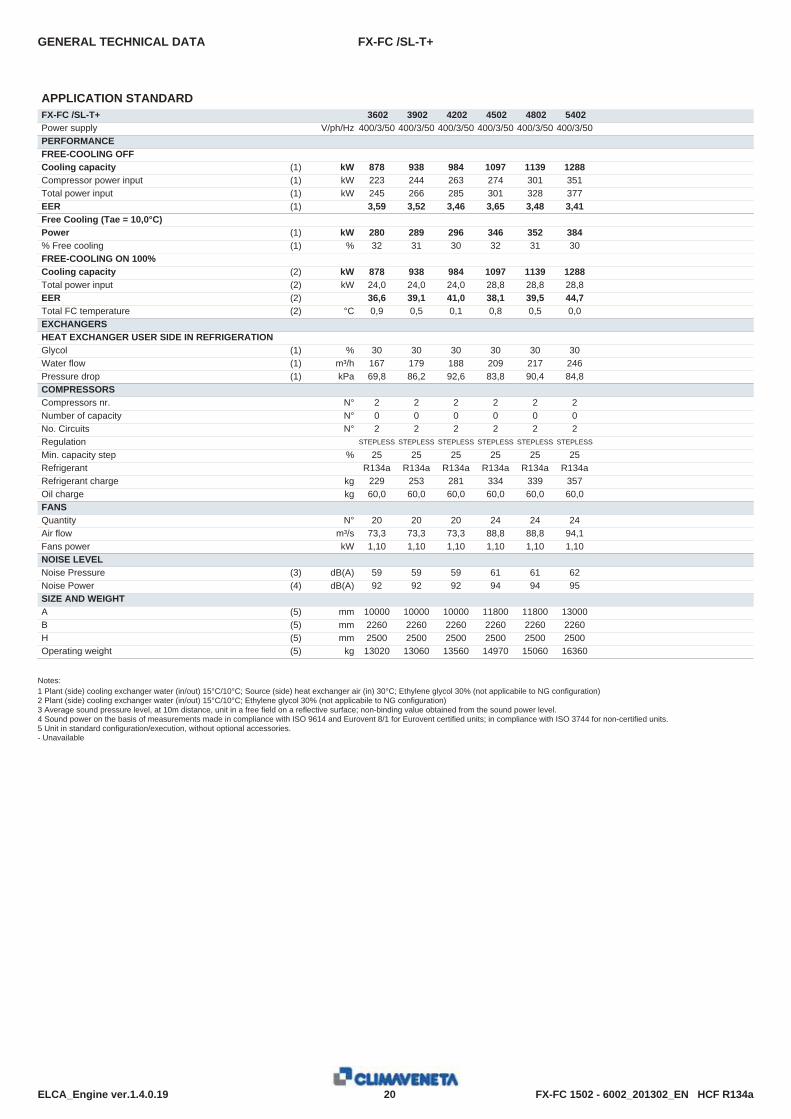
APPLICATION STANDARDFX-FC /SL-T+ 3602 3902 4202 4502 4802 5402Power supply V/ph/Hz 400/3/50 400/3/50 400/3/50 400/3/50 400/3/50 400/3/50PERFORMANCEFREE-COOLING OFFCooling capacity (1) kW 878 938 984 1097 1139 1288Compressor power input (1) kW 223 244 263 274 301 351Total power input (1) kW 245 266 285 301 328 377EER (1) 3,59 3,52 3,46 3,65 3,48 3,41Free Cooling (Tae = 10,0°C)Power (1) kW 280 289 296 346 352 384% Free cooling (1) % 32 31 30 32 31 30FREE-COOLING ON 100%Cooling capacity (2) kW 878 938 984 1097 1139 1288Total power input (2) kW 24,0 24,0 24,0 28,8 28,8 28,8EER (2) 36,6 39,1 41,0 38,1 39,5 44,7Total FC temperature (2) °C 0,9 0,5 0,1 0,8 0,5 0,0EXCHANGERSHEAT EXCHANGER USER SIDE IN REFRIGERATIONGlycol (1) % 30 30 30 30 30 30Water flow (1) m³/h 167 179 188 209 217 246Pressure drop (1) kPa 69,8 86,2 92,6 83,8 90,4 84,8COMPRESSORSCompressors nr. N° 2 2 2 2 2 2Number of capacity N° 0 0 0 0 0 0No. Circuits N° 2 2 2 2 2 2Regulation STEPLESS STEPLESS STEPLESS STEPLESS STEPLESS STEPLESS
Min. capacity step % 25 25 25 25 25 25Refrigerant R134a R134a R134a R134a R134a R134aRefrigerant charge kg 229 253 281 334 339 357Oil charge kg 60,0 60,0 60,0 60,0 60,0 60,0FANSQuantity N° 20 20 20 24 24 24Air flow m³/s 73,3 73,3 73,3 88,8 88,8 94,1Fans power kW 1,10 1,10 1,10 1,10 1,10 1,10NOISE LEVELNoise Pressure (3) dB(A) 59 59 59 61 61 62Noise Power (4) dB(A) 92 92 92 94 94 95SIZE AND WEIGHTA (5) mm 10000 10000 10000 11800 11800 13000B (5) mm 2260 2260 2260 2260 2260 2260H (5) mm 2500 2500 2500 2500 2500 2500Operating weight (5) kg 13020 13060 13560 14970 15060 16360
Notes:1 Plant (side) cooling exchanger water (in/out) 15°C/10°C; Source (side) heat exchanger air (in) 30°C; Ethylene glycol 30% (not applicabile to NG configuration)2 Plant (side) cooling exchanger water (in/out) 15°C/10°C; Ethylene glycol 30% (not applicabile to NG configuration)3 Average sound pressure level, at 10m distance, unit in a free field on a reflective surface; non-binding value obtained from the sound power level.4 Sound power on the basis of measurements made in compliance with ISO 9614 and Eurovent 8/1 for Eurovent certified units; in compliance with ISO 3744 for non-certified units.5 Unit in standard configuration/execution, without optional accessories.- Unavailable
FX-FC 1502 - 6002_201302_EN HCF R134a21ELCA_Engine ver.1.4.0.19
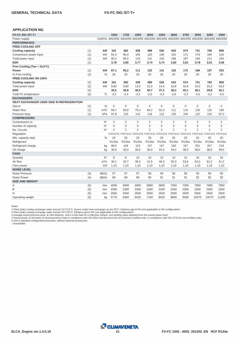
FX-FC /NG /ST-T+GENERAL TECHNICAL DATA
APPLICATION NGFX-FC /NG /ST-T+ 1502 1702 1902 2002 2202 2602 2702 3002 3202 3402Power supply V/ph/Hz 400/3/50 400/3/50 400/3/50 400/3/50 400/3/50 400/3/50 400/3/50 400/3/50 400/3/50 400/3/50PERFORMANCEFREE-COOLING OFFCooling capacity (1) kW 341 382 438 489 536 642 674 731 765 808Compressor power input (1) kW 81,4 90,4 105 120 130 152 171 176 194 216Total power input (1) kW 90,2 99,2 116 131 143 168 187 193 212 234EER (1) 3,78 3,85 3,77 3,74 3,74 3,82 3,61 3,78 3,61 3,46Free Cooling (Tae = 10,0°C)Power (1) kW 87,1 95,2 111 122 141 162 172 186 197 203% Free cooling (1) % 26 25 25 25 26 25 26 25 26 25FREE-COOLING ON 100%Cooling capacity (2) kW 341 382 438 489 536 642 674 731 765 808Total power input (2) kW 9,60 9,60 12,0 12,0 14,4 16,8 16,8 19,2 19,2 19,2EER (2) 35,5 39,8 36,5 40,7 37,2 38,2 40,1 38,1 39,8 42,1Total FC temperature (2) °C -2,5 -2,4 -2,5 -2,5 -2,4 -2,6 -2,2 -2,5 -2,2 -2,5EXCHANGERSHEAT EXCHANGER USER SIDE IN REFRIGERATIONGlycol (1) % 0 0 0 0 0 0 0 0 0 0Water flow (1) m³/h 58,7 65,8 75,4 84,2 92,3 111 116 126 132 139Pressure drop (1) kPa 97,8 123 110 118 113 120 104 122 120 97,0COMPRESSORSCompressors nr. N° 2 2 2 2 2 2 2 2 2 2Number of capacity N° 0 0 0 0 0 0 0 0 0 0No. Circuits N° 2 2 2 2 2 2 2 2 2 2Regulation STEPLESS STEPLESS STEPLESS STEPLESS STEPLESS STEPLESS STEPLESS STEPLESS STEPLESS STEPLESS
Min. capacity step % 25 25 25 25 25 25 25 25 25 25Refrigerant R134a R134a R134a R134a R134a R134a R134a R134a R134a R134aRefrigerant charge kg 98,0 104 124 137 147 162 167 201 207 219Oil charge kg 30,0 30,0 30,0 30,0 44,0 44,0 38,0 38,0 38,0 49,0FANSQuantity N° 8 8 10 10 12 14 14 16 16 16Air flow m³/s 30,1 33,7 38,3 41,5 46,3 55,3 53,6 63,3 61,2 61,2Fans power kW 1,10 1,10 1,10 1,10 1,10 1,10 1,10 1,10 1,10 1,10NOISE LEVELNoise Pressure (3) dB(A) 57 57 57 58 59 58 58 59 59 59Noise Power (4) dB(A) 89 89 89 90 91 91 91 92 92 92SIZE AND WEIGHTA (5) mm 4000 4900 4900 5800 5800 7000 7000 7900 7900 7900B (5) mm 2260 2260 2260 2260 2260 2260 2260 2260 2260 2260H (5) mm 2500 2500 2500 2500 2500 2500 2500 2500 2500 2500Operating weight (5) kg 5770 6360 6520 7160 8020 8890 9590 10070 10570 11290
Notes:1 Plant (side) cooling exchanger water (in/out) 15°C/10°C; Source (side) heat exchanger air (in) 30°C; Ethylene glycol 0% (not applicabile to NG configuration)2 Plant (side) cooling exchanger water (in/out) 15°C/10°C; Ethylene glycol 0% (not applicabile to NG configuration)3 Average sound pressure level, at 10m distance, unit in a free field on a reflective surface; non-binding value obtained from the sound power level.4 Sound power on the basis of measurements made in compliance with ISO 9614 and Eurovent 8/1 for Eurovent certified units; in compliance with ISO 3744 for non-certified units.5 Unit in standard configuration/execution, without optional accessories.- Unavailable

FX-FC 1502 - 6002_201302_EN HCF R134a22ELCA_Engine ver.1.4.0.19
FX-FC /NG /ST-T+GENERAL TECHNICAL DATA
APPLICATION NGFX-FC /NG /ST-T+ 3602 3902 4202 4502 4802 5402Power supply V/ph/Hz 400/3/50 400/3/50 400/3/50 400/3/50 400/3/50 400/3/50PERFORMANCEFREE-COOLING OFFCooling capacity (1) kW 902 964 1010 1126 1169 1323Compressor power input (1) kW 224 245 264 276 303 353Total power input (1) kW 246 267 286 302 329 380EER (1) 3,67 3,61 3,54 3,73 3,55 3,48Free Cooling (Tae = 10,0°C)Power (1) kW 234 241 247 288 294 320% Free cooling (1) % 26 25 24 26 25 24FREE-COOLING ON 100%Cooling capacity (2) kW 902 964 1010 1126 1169 1323Total power input (2) kW 24,0 24,0 24,0 28,8 28,8 28,8EER (2) 37,6 40,2 42,1 39,1 40,6 45,9Total FC temperature (2) °C -2,2 -2,6 -3,0 -2,3 -2,6 -3,1EXCHANGERSHEAT EXCHANGER USER SIDE IN REFRIGERATIONGlycol (1) % 0 0 0 0 0 0Water flow (1) m³/h 155 166 174 194 201 228Pressure drop (1) kPa 113 135 148 132 142 156COMPRESSORSCompressors nr. N° 2 2 2 2 2 2Number of capacity N° 0 0 0 0 0 0No. Circuits N° 2 2 2 2 2 2Regulation STEPLESS STEPLESS STEPLESS STEPLESS STEPLESS STEPLESS
Min. capacity step % 25 25 25 25 25 25Refrigerant R134a R134a R134a R134a R134a R134aRefrigerant charge kg 229 253 281 334 339 357Oil charge kg 60,0 60,0 60,0 60,0 60,0 60,0FANSQuantity N° 20 20 20 24 24 24Air flow m³/s 73,3 73,3 73,3 88,8 88,8 94,1Fans power kW 1,10 1,10 1,10 1,10 1,10 1,10NOISE LEVELNoise Pressure (3) dB(A) 59 59 59 61 61 62Noise Power (4) dB(A) 92 92 92 94 94 95SIZE AND WEIGHTA (5) mm 10000 10000 10000 11800 11800 13000B (5) mm 2260 2260 2260 2260 2260 2260H (5) mm 2500 2500 2500 2500 2500 2500Operating weight (5) kg 13810 13850 13970 15590 15680 17220
Notes:1 Plant (side) cooling exchanger water (in/out) 15°C/10°C; Source (side) heat exchanger air (in) 30°C; Ethylene glycol 0% (not applicabile to NG configuration)2 Plant (side) cooling exchanger water (in/out) 15°C/10°C; Ethylene glycol 0% (not applicabile to NG configuration)3 Average sound pressure level, at 10m distance, unit in a free field on a reflective surface; non-binding value obtained from the sound power level.4 Sound power on the basis of measurements made in compliance with ISO 9614 and Eurovent 8/1 for Eurovent certified units; in compliance with ISO 3744 for non-certified units.5 Unit in standard configuration/execution, without optional accessories.- Unavailable
23
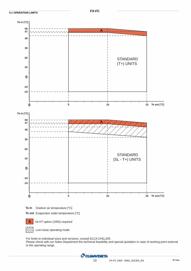
5.1 OPERATION LIMITS FX-FC
FX-FC 1502 - 6002_201302_EN
Te out [°C]
Ta in [°C]
-15
-10
10
5
STANDARD(T+) UNITS
47
kit HT option (1955) required
Low-noise operating mode
Evaporator outlet temperature [°C] Te out
Outdoor air temperature [°C]Ta in
40
0
0
A50
A
10 15
20
30
Te out [°C]
Ta in [°C]
-15
-10
10
5
STANDARD(SL - T+) UNITS
47
40
0
0
A50
10 15
20
30
For limits to individual sizes and versions, consult ELCA CHILLER. Please check with our Sales Department the technical feasibility and special quotation in case of working point external to the operating range.

HEAT
OPERATION LIMITS
24
FX-FC
FX-FC 1502 - 6002_201302_IT
5
5
FX-FC 1502 - 6002_201302_EN HCF R134a25ELCA_Engine ver.1.4.0.11
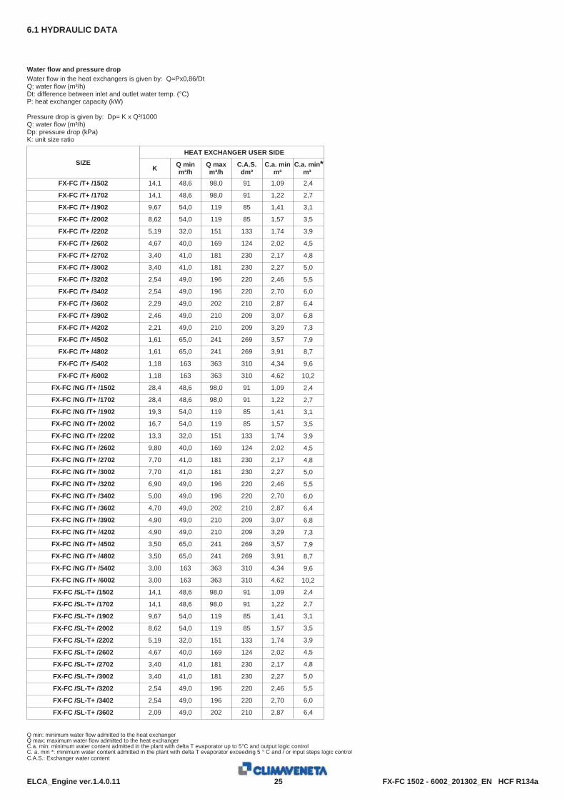
6.1 HYDRAULIC DATA
Water flow and pressure dropWater flow in the heat exchangers is given by: Q=Px0,86/DtQ: water flow (m³/h)Dt: difference between inlet and outlet water temp. (°C)P: heat exchanger capacity (kW)
Pressure drop is given by: Dp= K x Q²/1000Q: water flow (m³/h)Dp: pressure drop (kPa)K: unit size ratio
HEAT EXCHANGER USER SIDE
K Q minm³/h
Q maxm³/h
C.A.S.dm³
C.a. minm³
SIZE
FX-FC /T+ /1502 14,1 48,6 98,0 91 1,09
FX-FC /T+ /1702 14,1 48,6 98,0 91 1,22
FX-FC /T+ /1902 9,67 54,0 119 85 1,41
FX-FC /T+ /2002 8,62 54,0 119 85 1,57
FX-FC /T+ /2202 5,19 32,0 151 133 1,74
FX-FC /T+ /2602 4,67 40,0 169 124 2,02
FX-FC /T+ /2702 3,40 41,0 181 230 2,17
FX-FC /T+ /3002 3,40 41,0 181 230 2,27
FX-FC /T+ /3202 2,54 49,0 196 220 2,46
FX-FC /T+ /3402 2,54 49,0 196 220 2,70
FX-FC /T+ /3602 2,29 49,0 202 210 2,87
FX-FC /T+ /3902 2,46 49,0 210 209 3,07
FX-FC /T+ /4202 2,21 49,0 210 209 3,29
FX-FC /T+ /4502 1,61 65,0 241 269 3,57
FX-FC /T+ /4802 1,61 65,0 241 269 3,91
FX-FC /T+ /5402 1,18 163 363 310 4,34
FX-FC /T+ /6002 1,18 163 363 310 4,62
FX-FC /NG /T+ /1502 28,4 48,6 98,0 91 1,09
FX-FC /NG /T+ /1702 28,4 48,6 98,0 91 1,22
FX-FC /NG /T+ /1902 19,3 54,0 119 85 1,41
FX-FC /NG /T+ /2002 16,7 54,0 119 85 1,57
FX-FC /NG /T+ /2202 13,3 32,0 151 133 1,74
FX-FC /NG /T+ /2602 9,80 40,0 169 124 2,02
FX-FC /NG /T+ /2702 7,70 41,0 181 230 2,17
FX-FC /NG /T+ /3002 7,70 41,0 181 230 2,27
FX-FC /NG /T+ /3202 6,90 49,0 196 220 2,46
FX-FC /NG /T+ /3402 5,00 49,0 196 220 2,70
FX-FC /NG /T+ /3602 4,70 49,0 202 210 2,87
FX-FC /NG /T+ /3902 4,90 49,0 210 209 3,07
FX-FC /NG /T+ /4202 4,90 49,0 210 209 3,29
FX-FC /NG /T+ /4502 3,50 65,0 241 269 3,57
FX-FC /NG /T+ /4802 3,50 65,0 241 269 3,91
FX-FC /NG /T+ /5402 3,00 163 363 310 4,34
FX-FC /NG /T+ /6002 3,00 163 363 310 4,62
FX-FC /SL-T+ /1502 14,1 48,6 98,0 91 1,09
FX-FC /SL-T+ /1702 14,1 48,6 98,0 91 1,22
FX-FC /SL-T+ /1902 9,67 54,0 119 85 1,41
FX-FC /SL-T+ /2002 8,62 54,0 119 85 1,57
FX-FC /SL-T+ /2202 5,19 32,0 151 133 1,74
FX-FC /SL-T+ /2602 4,67 40,0 169 124 2,02
FX-FC /SL-T+ /2702 3,40 41,0 181 230 2,17
FX-FC /SL-T+ /3002 3,40 41,0 181 230 2,27
FX-FC /SL-T+ /3202 2,54 49,0 196 220 2,46
FX-FC /SL-T+ /3402 2,54 49,0 196 220 2,70
FX-FC /SL-T+ /3602 2,09 49,0 202 210 2,87
Q min: minimum water flow admitted to the heat exchangerQ max: maximum water flow admitted to the heat exchangerC.a. min: minimum water content admitted in the plant with delta T evaporator up to 5°C and output logic controlC. a. min *: minimum water content admitted in the plant with delta T evaporator exceeding 5 ° C and / or input steps logic control C.A.S.: Exchanger water content
C.a. min*m³2,4
2,7
3,1
3,5
3,9
4,5
4,8
5,0
5,5
6,0
6,4
6,8
7,3
7,9
8,7
9,6
10,2
2,4
2,7
3,1
3,5
3,9
4,5
4,8
5,0
5,5
6,0
6,4
6,8
7,3
7,9
8,7
9,6
10,2
2,4
2,7
3,1
3,5
3,9
4,5
4,8
5,0
5,5
6,0
6,4
FX-FC 1502 - 6002_201302_EN HCF R134a26ELCA_Engine ver.1.4.0.11
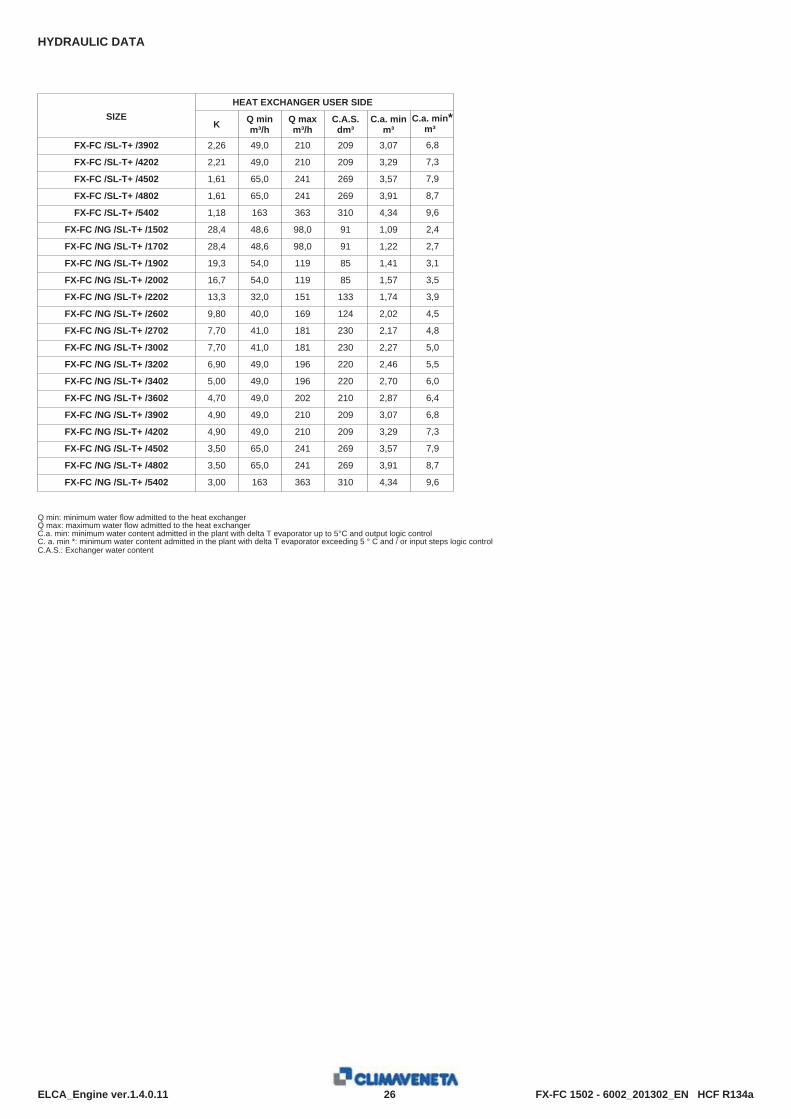
HYDRAULIC DATA
HEAT EXCHANGER USER SIDE
K Q minm³/h
Q maxm³/h
C.A.S.dm³
C.a. minm³
SIZE
FX-FC /SL-T+ /3902 2,26 49,0 210 209 3,07
FX-FC /SL-T+ /4202 2,21 49,0 210 209 3,29
FX-FC /SL-T+ /4502 1,61 65,0 241 269 3,57
FX-FC /SL-T+ /4802 1,61 65,0 241 269 3,91
FX-FC /SL-T+ /5402 1,18 163 363 310 4,34
FX-FC /NG /SL-T+ /1502 28,4 48,6 98,0 91 1,09
FX-FC /NG /SL-T+ /1702 28,4 48,6 98,0 91 1,22
FX-FC /NG /SL-T+ /1902 19,3 54,0 119 85 1,41
FX-FC /NG /SL-T+ /2002 16,7 54,0 119 85 1,57
FX-FC /NG /SL-T+ /2202 13,3 32,0 151 133 1,74
FX-FC /NG /SL-T+ /2602 9,80 40,0 169 124 2,02
FX-FC /NG /SL-T+ /2702 7,70 41,0 181 230 2,17
FX-FC /NG /SL-T+ /3002 7,70 41,0 181 230 2,27
FX-FC /NG /SL-T+ /3202 6,90 49,0 196 220 2,46
FX-FC /NG /SL-T+ /3402 5,00 49,0 196 220 2,70
FX-FC /NG /SL-T+ /3602 4,70 49,0 202 210 2,87
FX-FC /NG /SL-T+ /3902 4,90 49,0 210 209 3,07
FX-FC /NG /SL-T+ /4202 4,90 49,0 210 209 3,29
FX-FC /NG /SL-T+ /4502 3,50 65,0 241 269 3,57
FX-FC /NG /SL-T+ /4802 3,50 65,0 241 269 3,91
FX-FC /NG /SL-T+ /5402 3,00 163 363 310 4,34
Q min: minimum water flow admitted to the heat exchangerQ max: maximum water flow admitted to the heat exchangerC.a. min: minimum water content admitted in the plant with delta T evaporator up to 5°C and output logic controlC. a. min *: minimum water content admitted in the plant with delta T evaporator exceeding 5 ° C and / or input steps logic control C.A.S.: Exchanger water content
C.a. min*m³6,8
7,3
7,9
8,7
9,6
2,4
2,7
3,1
3,5
3,9
4,5
4,8
5,0
5,5
6,0
6,4
6,8
7,3
7,9
8,7
9,6

FX-FC 1502 - 6002_201302_EN HCF R134a27ELCA_Engine ver.1.4.0.15
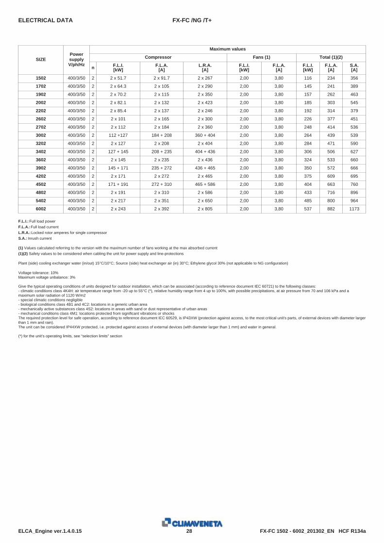
7.1 ELECTRICAL DATA
Maximum values
Compressor Fans (1) Total (1)(2)
n F.L.I.[kW]
F.L.A.[A]
L.R.A.[A]
F.L.I.[kW]
F.L.A.[A]
F.L.I.[kW]
F.L.A.[A]
S.A.[A]
SIZEPowersupplyV/ph/Hz
FX-FC /T+
1502 400/3/50 2 2 x 51.7 2 x 91.7 2 x 267 2,00 3,80 234116 356
1702 400/3/50 2 2 x 64.3 2 x 10⁵ 2 x 290 2,00 3,80 241145 389
1902 400/3/50 2 2 x 70.2 2 x 115 2 x 350 2,00 3,80 262157 463
2002 400/3/50 2 2 x 82.1 2 x 132 2 x 423 2,00 3,80 303185 545
2202 400/3/50 2 2 x 85.4 2 x 137 2 x 246 2,00 3,80 314192 379
2602 400/3/50 2 2 x 101 2 x 165 2 x 300 2,00 3,80 377226 451
2702 400/3/50 2 2 x 112 2 x 184 2 x 360 2,00 3,80 414248 536
3002 400/3/50 2 112 +127 184 + 208 360 + 404 2,00 3,80 439264 539
3202 400/3/50 2 2 x 127 2 x 208 2 x 404 2,00 3,80 471284 590
3402 400/3/50 2 127 + 145 208 + 235 404 + 436 2,00 3,80 506306 627
3602 400/3/50 2 2 x 145 2 x 235 2 x 436 2,00 3,80 533324 660
3902 400/3/50 2 145 + 171 235 + 272 436 + 465 2,00 3,80 572350 666
4202 400/3/50 2 2 x 171 2 x 272 2 x 465 2,00 3,80 609375 695
4502 400/3/50 2 171 + 191 272 + 310 465 + 586 2,00 3,80 663404 760
4802 400/3/50 2 2 x 191 2 x 310 2 x 586 2,00 3,80 716433 896
5402 400/3/50 2 2 x 217 2 x 351 2 x 650 2,00 3,80 800485 964
6002 400/3/50 2 2 x 243 2 x 392 2 x 805 2,00 3,80 882537 1173
F.L.I.: Full load powerF.L.A.:Full load currentL.R.A.:Locked rotor amperes for single compressorS.A.: Inrush current
(1) Values calculated referring to the version with the maximum number of fans working at the max absorbed current(1)(2) Safety values to be considered when cabling the unit for power supply and line-protections
Plant (side) cooling exchanger water (in/out) 15°C/10°C; Source (side) heat exchanger air (in) 30°C; Ethylene glycol 30% (not applicabile to NG configuration)
Voltage tolerance: 10%Maximum voltage unbalance: 3%
Give the typical operating conditions of units designed for outdoor installation, which can be associated (according to reference document IEC 60721) to the following classes:- climatic conditions class 4K4H: air temperature range from -20 up to 55°C (*), relative humidity range from 4 up to 100%, with possible precipitations, at air pressure from 70 and 106 kPa and amaximum solar radiation of 1120 W/m2- special climatic conditions negligible- biological conditions class 4B1 and 4C2: locations in a generic urban area- mechanically active substances class 4S2: locations in areas with sand or dust representative of urban areas- mechanical conditions class 4M1: locations protected from significant vibrations or shocksThe required protection level for safe operation, according to reference document IEC 60529, is IP43XW (protection against access, to the most critical unit's parts, of external devices with diameter largerthan 1 mm and rain).The unit can be considered IP44XW protected, i.e. protected against access of external devices (with diameter larger than 1 mm) and water in general.
(*) for the unit’s operating limits, see “selection limits” section
FX-FC 1502 - 6002_201302_EN HCF R134a28ELCA_Engine ver.1.4.0.15
ELECTRICAL DATA
Maximum values
Compressor Fans (1) Total (1)(2)
n F.L.I.[kW]
F.L.A.[A]
L.R.A.[A]
F.L.I.[kW]
F.L.A.[A]
F.L.I.[kW]
F.L.A.[A]
S.A.[A]
SIZEPowersupplyV/ph/Hz
FX-FC /NG /T+
1502 400/3/50 2 2 x 51.7 2 x 91.7 2 x 267 2,00 3,80 234116 356
1702 400/3/50 2 2 x 64.3 2 x 10⁵ 2 x 290 2,00 3,80 241145 389
1902 400/3/50 2 2 x 70.2 2 x 115 2 x 350 2,00 3,80 262157 463
2002 400/3/50 2 2 x 82.1 2 x 132 2 x 423 2,00 3,80 303185 545
2202 400/3/50 2 2 x 85.4 2 x 137 2 x 246 2,00 3,80 314192 379
2602 400/3/50 2 2 x 101 2 x 165 2 x 300 2,00 3,80 377226 451
2702 400/3/50 2 2 x 112 2 x 184 2 x 360 2,00 3,80 414248 536
3002 400/3/50 2 112 +127 184 + 208 360 + 404 2,00 3,80 439264 539
3202 400/3/50 2 2 x 127 2 x 208 2 x 404 2,00 3,80 471284 590
3402 400/3/50 2 127 + 145 208 + 235 404 + 436 2,00 3,80 506306 627
3602 400/3/50 2 2 x 145 2 x 235 2 x 436 2,00 3,80 533324 660
3902 400/3/50 2 145 + 171 235 + 272 436 + 465 2,00 3,80 572350 666
4202 400/3/50 2 2 x 171 2 x 272 2 x 465 2,00 3,80 609375 695
4502 400/3/50 2 171 + 191 272 + 310 465 + 586 2,00 3,80 663404 760
4802 400/3/50 2 2 x 191 2 x 310 2 x 586 2,00 3,80 716433 896
5402 400/3/50 2 2 x 217 2 x 351 2 x 650 2,00 3,80 800485 964
6002 400/3/50 2 2 x 243 2 x 392 2 x 805 2,00 3,80 882537 1173
F.L.I.: Full load powerF.L.A.:Full load currentL.R.A.:Locked rotor amperes for single compressorS.A.: Inrush current
(1) Values calculated referring to the version with the maximum number of fans working at the max absorbed current(1)(2) Safety values to be considered when cabling the unit for power supply and line-protections
Plant (side) cooling exchanger water (in/out) 15°C/10°C; Source (side) heat exchanger air (in) 30°C; Ethylene glycol 30% (not applicabile to NG configuration)
Voltage tolerance: 10%Maximum voltage unbalance: 3%
Give the typical operating conditions of units designed for outdoor installation, which can be associated (according to reference document IEC 60721) to the following classes:- climatic conditions class 4K4H: air temperature range from -20 up to 55°C (*), relative humidity range from 4 up to 100%, with possible precipitations, at air pressure from 70 and 106 kPa and amaximum solar radiation of 1120 W/m2- special climatic conditions negligible- biological conditions class 4B1 and 4C2: locations in a generic urban area- mechanically active substances class 4S2: locations in areas with sand or dust representative of urban areas- mechanical conditions class 4M1: locations protected from significant vibrations or shocksThe required protection level for safe operation, according to reference document IEC 60529, is IP43XW (protection against access, to the most critical unit's parts, of external devices with diameter largerthan 1 mm and rain).The unit can be considered IP44XW protected, i.e. protected against access of external devices (with diameter larger than 1 mm) and water in general.
(*) for the unit’s operating limits, see “selection limits” section
FX-FC 1502 - 6002_201302_EN HCF R134a29ELCA_Engine ver.1.4.0.15
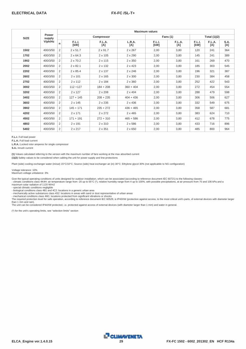
ELECTRICAL DATA
Maximum values
Compressor Fans (1) Total (1)(2)
n F.L.I.[kW]
F.L.A.[A]
L.R.A.[A]
F.L.I.[kW]
F.L.A.[A]
F.L.I.[kW]
F.L.A.[A]
S.A.[A]
SIZEPowersupplyV/ph/Hz
FX-FC /SL-T+
1502 400/3/50 2 2 x 51.7 2 x 91.7 2 x 267 2,00 3,80 241120 364
1702 400/3/50 2 2 x 64.3 2 x 10⁵ 2 x 290 2,00 3,80 241145 389
1902 400/3/50 2 2 x 70.2 2 x 115 2 x 350 2,00 3,80 269161 470
2002 400/3/50 2 2 x 82.1 2 x 132 2 x 423 2,00 3,80 303185 545
2202 400/3/50 2 2 x 85.4 2 x 137 2 x 246 2,00 3,80 321196 387
2602 400/3/50 2 2 x 101 2 x 165 2 x 300 2,00 3,80 384230 458
2702 400/3/50 2 2 x 112 2 x 184 2 x 360 2,00 3,80 422252 543
3002 400/3/50 2 112 +127 184 + 208 360 + 404 2,00 3,80 454272 554
3202 400/3/50 2 2 x 127 2 x 208 2 x 404 2,00 3,80 479288 598
3402 400/3/50 2 127 + 145 208 + 235 404 + 436 2,00 3,80 506306 627
3602 400/3/50 2 2 x 145 2 x 235 2 x 436 2,00 3,80 549332 675
3902 400/3/50 2 145 + 171 235 + 272 436 + 465 2,00 3,80 587358 681
4202 400/3/50 2 2 x 171 2 x 272 2 x 465 2,00 3,80 624383 710
4502 400/3/50 2 171 + 191 272 + 310 465 + 586 2,00 3,80 678412 775
4802 400/3/50 2 2 x 191 2 x 310 2 x 586 2,00 3,80 716433 896
5402 400/3/50 2 2 x 217 2 x 351 2 x 650 2,00 3,80 800485 964
F.L.I.: Full load powerF.L.A.:Full load currentL.R.A.:Locked rotor amperes for single compressorS.A.: Inrush current
(1) Values calculated referring to the version with the maximum number of fans working at the max absorbed current(1)(2) Safety values to be considered when cabling the unit for power supply and line-protections
Plant (side) cooling exchanger water (in/out) 15°C/10°C; Source (side) heat exchanger air (in) 30°C; Ethylene glycol 30% (not applicabile to NG configuration)
Voltage tolerance: 10%Maximum voltage unbalance: 3%
Give the typical operating conditions of units designed for outdoor installation, which can be associated (according to reference document IEC 60721) to the following classes:- climatic conditions class 4K4H: air temperature range from -20 up to 55°C (*), relative humidity range from 4 up to 100%, with possible precipitations, at air pressure from 70 and 106 kPa and amaximum solar radiation of 1120 W/m2- special climatic conditions negligible- biological conditions class 4B1 and 4C2: locations in a generic urban area- mechanically active substances class 4S2: locations in areas with sand or dust representative of urban areas- mechanical conditions class 4M1: locations protected from significant vibrations or shocksThe required protection level for safe operation, according to reference document IEC 60529, is IP43XW (protection against access, to the most critical unit's parts, of external devices with diameter largerthan 1 mm and rain).The unit can be considered IP44XW protected, i.e. protected against access of external devices (with diameter larger than 1 mm) and water in general.
(*) for the unit’s operating limits, see “selection limits” section
FX-FC 1502 - 6002_201302_EN HCF R134a30ELCA_Engine ver.1.4.0.15
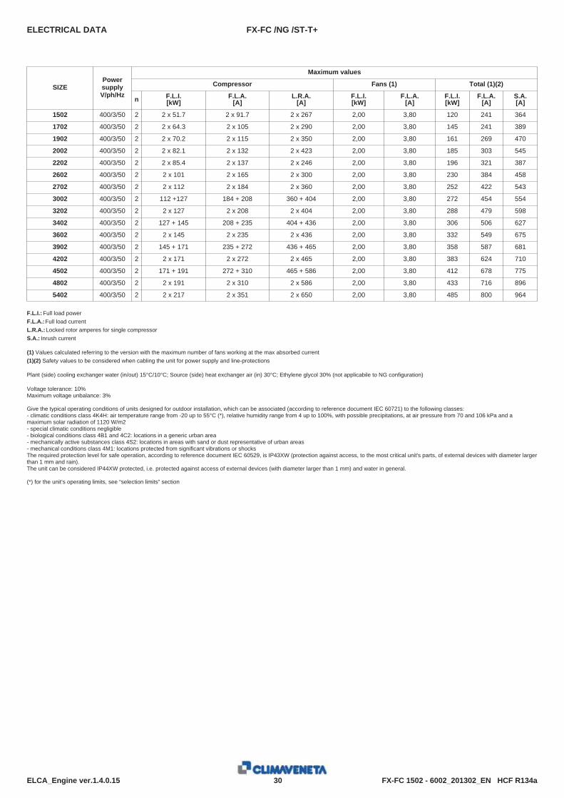
ELECTRICAL DATA
Maximum values
Compressor Fans (1) Total (1)(2)
n F.L.I.[kW]
F.L.A.[A]
L.R.A.[A]
F.L.I.[kW]
F.L.A.[A]
F.L.I.[kW]
F.L.A.[A]
S.A.[A]
SIZEPowersupplyV/ph/Hz
FX-FC /NG /ST-T+
1502 400/3/50 2 2 x 51.7 2 x 91.7 2 x 267 2,00 3,80 241120 364
1702 400/3/50 2 2 x 64.3 2 x 10⁵ 2 x 290 2,00 3,80 241145 389
1902 400/3/50 2 2 x 70.2 2 x 115 2 x 350 2,00 3,80 269161 470
2002 400/3/50 2 2 x 82.1 2 x 132 2 x 423 2,00 3,80 303185 545
2202 400/3/50 2 2 x 85.4 2 x 137 2 x 246 2,00 3,80 321196 387
2602 400/3/50 2 2 x 101 2 x 165 2 x 300 2,00 3,80 384230 458
2702 400/3/50 2 2 x 112 2 x 184 2 x 360 2,00 3,80 422252 543
3002 400/3/50 2 112 +127 184 + 208 360 + 404 2,00 3,80 454272 554
3202 400/3/50 2 2 x 127 2 x 208 2 x 404 2,00 3,80 479288 598
3402 400/3/50 2 127 + 145 208 + 235 404 + 436 2,00 3,80 506306 627
3602 400/3/50 2 2 x 145 2 x 235 2 x 436 2,00 3,80 549332 675
3902 400/3/50 2 145 + 171 235 + 272 436 + 465 2,00 3,80 587358 681
4202 400/3/50 2 2 x 171 2 x 272 2 x 465 2,00 3,80 624383 710
4502 400/3/50 2 171 + 191 272 + 310 465 + 586 2,00 3,80 678412 775
4802 400/3/50 2 2 x 191 2 x 310 2 x 586 2,00 3,80 716433 896
5402 400/3/50 2 2 x 217 2 x 351 2 x 650 2,00 3,80 800485 964
F.L.I.: Full load powerF.L.A.:Full load currentL.R.A.:Locked rotor amperes for single compressorS.A.: Inrush current
(1) Values calculated referring to the version with the maximum number of fans working at the max absorbed current(1)(2) Safety values to be considered when cabling the unit for power supply and line-protections
Plant (side) cooling exchanger water (in/out) 15°C/10°C; Source (side) heat exchanger air (in) 30°C; Ethylene glycol 30% (not applicabile to NG configuration)
Voltage tolerance: 10%Maximum voltage unbalance: 3%
Give the typical operating conditions of units designed for outdoor installation, which can be associated (according to reference document IEC 60721) to the following classes:- climatic conditions class 4K4H: air temperature range from -20 up to 55°C (*), relative humidity range from 4 up to 100%, with possible precipitations, at air pressure from 70 and 106 kPa and amaximum solar radiation of 1120 W/m2- special climatic conditions negligible- biological conditions class 4B1 and 4C2: locations in a generic urban area- mechanically active substances class 4S2: locations in areas with sand or dust representative of urban areas- mechanical conditions class 4M1: locations protected from significant vibrations or shocksThe required protection level for safe operation, according to reference document IEC 60529, is IP43XW (protection against access, to the most critical unit's parts, of external devices with diameter largerthan 1 mm and rain).The unit can be considered IP44XW protected, i.e. protected against access of external devices (with diameter larger than 1 mm) and water in general.
(*) for the unit’s operating limits, see “selection limits” section

FX-FC 1502 - 6002_201302_EN HCF R134a31ELCA_Engine ver.1.4.0.15
8.1 FULL LOAD SOUND LEVEL
SOUND POWER
Octave band [Hz]
63 125 250 500 1000 2000 4000 8000SIZETotal sound
leveldB(A)
Sound power level dB
FX-FC /T+
1502 91 96 98 96 95 89 83 73 99
1702 92 97 99 97 96 90 84 74 100
1902 92 97 99 97 96 90 84 74 100
2002 92 97 99 97 96 90 84 74 100
2202 93 98 100 98 97 91 85 75 101
2602 94 99 101 99 98 92 86 76 102
2702 94 99 101 99 98 92 86 76 102
3002 94 99 101 99 98 92 86 76 102
3202 94 99 101 99 98 92 86 76 102
3402 94 99 101 99 98 92 86 76 102
3602 95 100 102 100 99 93 87 77 103
3902 95 100 102 100 99 93 87 77 103
4202 95 100 102 100 99 93 87 77 103
4502 97 102 104 102 101 95 89 79 105
4802 98 103 105 103 102 96 90 80 106
5402 98 103 105 103 102 96 90 80 106
6002 98 103 105 103 102 96 90 80 106
Working conditionsPlant (side) cooling exchanger water (in/out) 15°C/10°C; Source (side) heat exchanger air (in) 30°C; Ethylene glycol 30% (not applicabile to NG configuration)Sound power in compliance with ISO 3744 for non-certified units.Such certification refers specifically to the sound Power Level in dB(A). This is therefore the only acoustic data to be considered as binding.
SOUND PRESSURE LEVEL
Octave band [Hz]
63 125 250 500 1000 2000 4000 8000SIZETotal sound
leveldB(A)
Sound pressure level dB
FX-FC /T+
1502 59 64 66 64 63 57 51 41 67
1702 60 65 67 65 64 58 52 42 68
1902 60 65 67 65 64 58 52 42 68
2002 60 65 67 65 64 58 52 42 68
2202 61 66 68 66 65 59 53 43 69
2602 62 67 69 67 66 60 54 44 70
2702 61 66 68 66 65 59 53 43 69
3002 61 66 68 66 65 59 53 43 69
3202 61 66 68 66 65 59 53 43 69
3402 61 66 68 66 65 59 53 43 69
3602 62 67 69 67 66 60 54 44 70
3902 62 67 69 67 66 60 54 44 70
4202 62 67 69 67 66 60 54 44 70
4502 64 69 71 69 68 62 56 46 72
4802 65 70 72 70 69 63 57 47 73
5402 65 70 72 70 69 63 57 47 73
6002 65 70 72 70 69 63 57 47 73
Working conditionsPlant (side) cooling exchanger water (in/out) 15°C/10°C; Source (side) heat exchanger air (in) 30°C; Ethylene glycol 30% (not applicabile to NG configuration)Average sound pressure level, at 10m distance, unit in a free field on a reflective surface; non-binding value obtained from the sound power level.
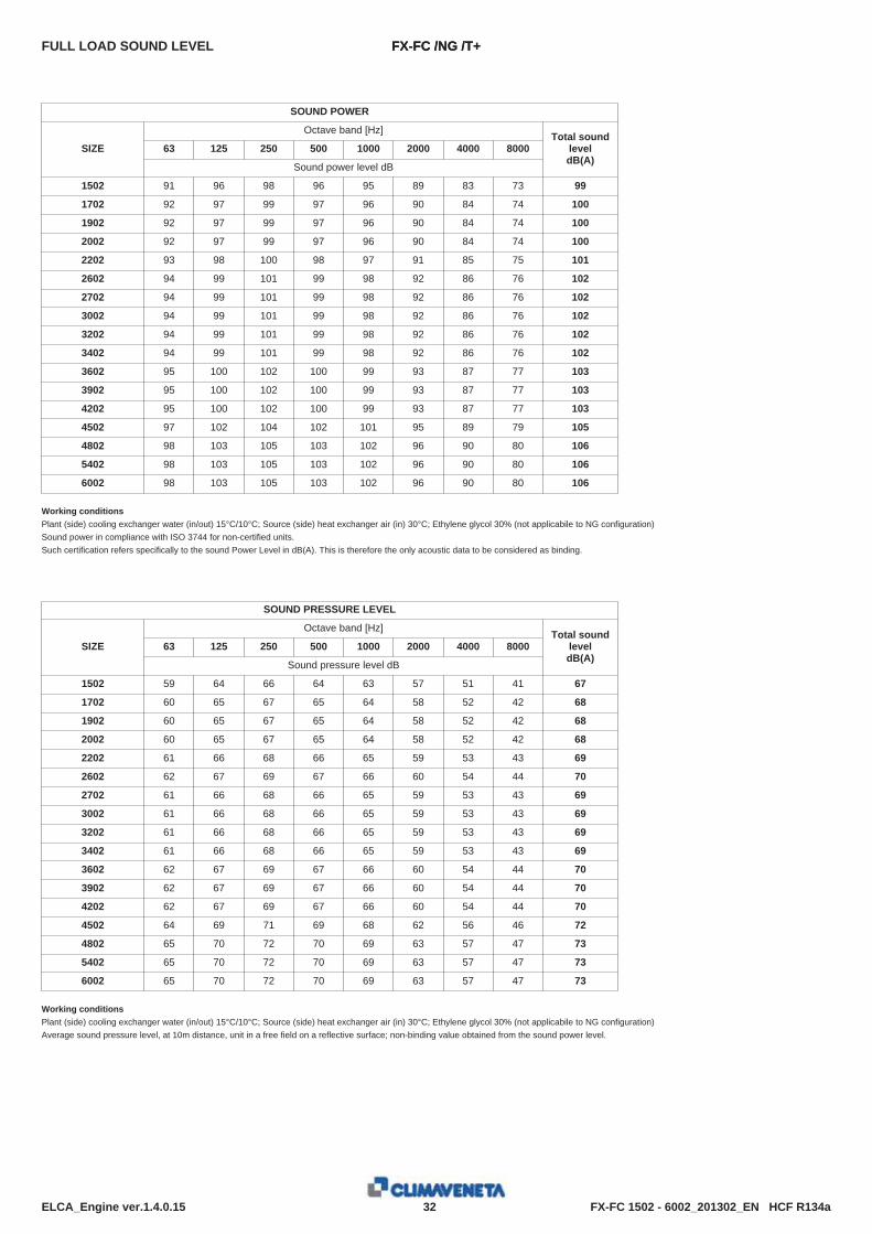
FX-FC 1502 - 6002_201302_EN HCF R134a32ELCA_Engine ver.1.4.0.15
FULL LOAD SOUND LEVEL
SOUND POWER
Octave band [Hz]
63 125 250 500 1000 2000 4000 8000SIZETotal sound
leveldB(A)
Sound power level dB
FX-FC /NG /T+
1502 91 96 98 96 95 89 83 73 99
1702 92 97 99 97 96 90 84 74 100
1902 92 97 99 97 96 90 84 74 100
2002 92 97 99 97 96 90 84 74 100
2202 93 98 100 98 97 91 85 75 101
2602 94 99 101 99 98 92 86 76 102
2702 94 99 101 99 98 92 86 76 102
3002 94 99 101 99 98 92 86 76 102
3202 94 99 101 99 98 92 86 76 102
3402 94 99 101 99 98 92 86 76 102
3602 95 100 102 100 99 93 87 77 103
3902 95 100 102 100 99 93 87 77 103
4202 95 100 102 100 99 93 87 77 103
4502 97 102 104 102 101 95 89 79 105
4802 98 103 105 103 102 96 90 80 106
5402 98 103 105 103 102 96 90 80 106
6002 98 103 105 103 102 96 90 80 106
Working conditionsPlant (side) cooling exchanger water (in/out) 15°C/10°C; Source (side) heat exchanger air (in) 30°C; Ethylene glycol 30% (not applicabile to NG configuration)Sound power in compliance with ISO 3744 for non-certified units.Such certification refers specifically to the sound Power Level in dB(A). This is therefore the only acoustic data to be considered as binding.
SOUND PRESSURE LEVEL
Octave band [Hz]
63 125 250 500 1000 2000 4000 8000SIZETotal sound
leveldB(A)
Sound pressure level dB
FX-FC /NG /T+
1502 59 64 66 64 63 57 51 41 67
1702 60 65 67 65 64 58 52 42 68
1902 60 65 67 65 64 58 52 42 68
2002 60 65 67 65 64 58 52 42 68
2202 61 66 68 66 65 59 53 43 69
2602 62 67 69 67 66 60 54 44 70
2702 61 66 68 66 65 59 53 43 69
3002 61 66 68 66 65 59 53 43 69
3202 61 66 68 66 65 59 53 43 69
3402 61 66 68 66 65 59 53 43 69
3602 62 67 69 67 66 60 54 44 70
3902 62 67 69 67 66 60 54 44 70
4202 62 67 69 67 66 60 54 44 70
4502 64 69 71 69 68 62 56 46 72
4802 65 70 72 70 69 63 57 47 73
5402 65 70 72 70 69 63 57 47 73
6002 65 70 72 70 69 63 57 47 73
Working conditionsPlant (side) cooling exchanger water (in/out) 15°C/10°C; Source (side) heat exchanger air (in) 30°C; Ethylene glycol 30% (not applicabile to NG configuration)Average sound pressure level, at 10m distance, unit in a free field on a reflective surface; non-binding value obtained from the sound power level.
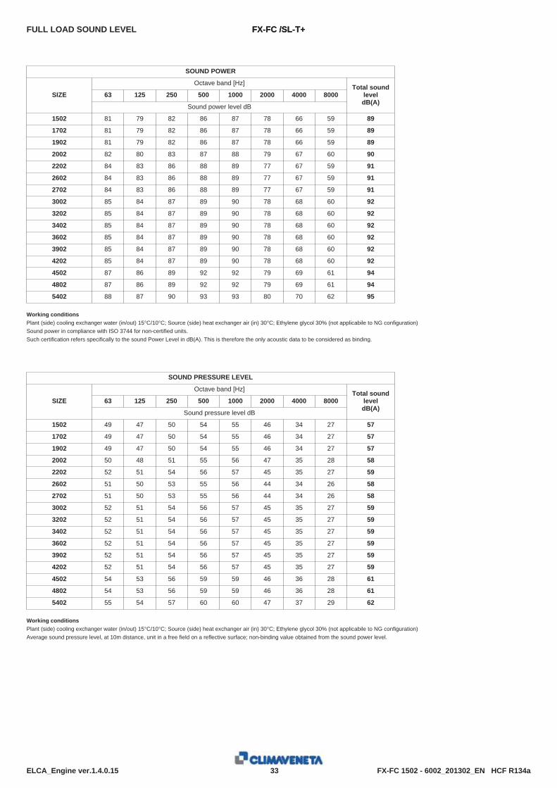
FX-FC 1502 - 6002_201302_EN HCF R134a33ELCA_Engine ver.1.4.0.15
FULL LOAD SOUND LEVEL
SOUND POWER
Octave band [Hz]
63 125 250 500 1000 2000 4000 8000SIZETotal sound
leveldB(A)
Sound power level dB
FX-FC /SL-T+
1502 81 79 82 86 87 78 66 59 89
1702 81 79 82 86 87 78 66 59 89
1902 81 79 82 86 87 78 66 59 89
2002 82 80 83 87 88 79 67 60 90
2202 84 83 86 88 89 77 67 59 91
2602 84 83 86 88 89 77 67 59 91
2702 84 83 86 88 89 77 67 59 91
3002 85 84 87 89 90 78 68 60 92
3202 85 84 87 89 90 78 68 60 92
3402 85 84 87 89 90 78 68 60 92
3602 85 84 87 89 90 78 68 60 92
3902 85 84 87 89 90 78 68 60 92
4202 85 84 87 89 90 78 68 60 92
4502 87 86 89 92 92 79 69 61 94
4802 87 86 89 92 92 79 69 61 94
5402 88 87 90 93 93 80 70 62 95
Working conditionsPlant (side) cooling exchanger water (in/out) 15°C/10°C; Source (side) heat exchanger air (in) 30°C; Ethylene glycol 30% (not applicabile to NG configuration)Sound power in compliance with ISO 3744 for non-certified units.Such certification refers specifically to the sound Power Level in dB(A). This is therefore the only acoustic data to be considered as binding.
SOUND PRESSURE LEVEL
Octave band [Hz]
63 125 250 500 1000 2000 4000 8000SIZETotal sound
leveldB(A)
Sound pressure level dB
FX-FC /SL-T+
1502 49 47 50 54 55 46 34 27 57
1702 49 47 50 54 55 46 34 27 57
1902 49 47 50 54 55 46 34 27 57
2002 50 48 51 55 56 47 35 28 58
2202 52 51 54 56 57 45 35 27 59
2602 51 50 53 55 56 44 34 26 58
2702 51 50 53 55 56 44 34 26 58
3002 52 51 54 56 57 45 35 27 59
3202 52 51 54 56 57 45 35 27 59
3402 52 51 54 56 57 45 35 27 59
3602 52 51 54 56 57 45 35 27 59
3902 52 51 54 56 57 45 35 27 59
4202 52 51 54 56 57 45 35 27 59
4502 54 53 56 59 59 46 36 28 61
4802 54 53 56 59 59 46 36 28 61
5402 55 54 57 60 60 47 37 29 62
Working conditionsPlant (side) cooling exchanger water (in/out) 15°C/10°C; Source (side) heat exchanger air (in) 30°C; Ethylene glycol 30% (not applicabile to NG configuration)Average sound pressure level, at 10m distance, unit in a free field on a reflective surface; non-binding value obtained from the sound power level.

FX-FC 1502 - 6002_201302_EN HCF R134a34ELCA_Engine ver.1.4.0.15
FULL LOAD SOUND LEVEL
SOUND POWER
Octave band [Hz]
63 125 250 500 1000 2000 4000 8000SIZETotal sound
leveldB(A)
Sound power level dB
FX-FC /NG /ST-T+
1502 81 79 82 86 87 78 66 59 89
1702 81 79 82 86 87 78 66 59 89
1902 81 79 82 86 87 78 66 59 89
2002 82 80 83 87 88 79 67 60 90
2202 84 83 86 88 89 77 67 59 91
2602 84 83 86 88 89 77 67 59 91
2702 84 83 86 88 89 77 67 59 91
3002 85 84 87 89 90 78 68 60 92
3202 85 84 87 89 90 78 68 60 92
3402 85 84 87 89 90 78 68 60 92
3602 85 84 87 89 90 78 68 60 92
3902 85 84 87 89 90 78 68 60 92
4202 85 84 87 89 90 78 68 60 92
4502 87 86 89 92 92 79 69 61 94
4802 87 86 89 92 92 79 69 61 94
5402 88 87 90 93 93 80 70 62 95
Working conditionsPlant (side) cooling exchanger water (in/out) 15°C/10°C; Source (side) heat exchanger air (in) 30°C; Ethylene glycol 30% (not applicabile to NG configuration)Sound power in compliance with ISO 3744 for non-certified units.Such certification refers specifically to the sound Power Level in dB(A). This is therefore the only acoustic data to be considered as binding.
SOUND PRESSURE LEVEL
Octave band [Hz]
63 125 250 500 1000 2000 4000 8000SIZETotal sound
leveldB(A)
Sound pressure level dB
FX-FC /NG /ST-T+
1502 49 47 50 54 55 46 34 27 57
1702 49 47 50 54 55 46 34 27 57
1902 49 47 50 54 55 46 34 27 57
2002 50 48 51 55 56 47 35 28 58
2202 52 51 54 56 57 45 35 27 59
2602 51 50 53 55 56 44 34 26 58
2702 51 50 53 55 56 44 34 26 58
3002 52 51 54 56 57 45 35 27 59
3202 52 51 54 56 57 45 35 27 59
3402 52 51 54 56 57 45 35 27 59
3602 52 51 54 56 57 45 35 27 59
3902 52 51 54 56 57 45 35 27 59
4202 52 51 54 56 57 45 35 27 59
4502 54 53 56 59 59 46 36 28 61
4802 54 53 56 59 59 46 36 28 61
5402 55 54 57 60 60 47 37 29 62
Working conditionsPlant (side) cooling exchanger water (in/out) 15°C/10°C; Source (side) heat exchanger air (in) 30°C; Ethylene glycol 30% (not applicabile to NG configuration)Average sound pressure level, at 10m distance, unit in a free field on a reflective surface; non-binding value obtained from the sound power level.
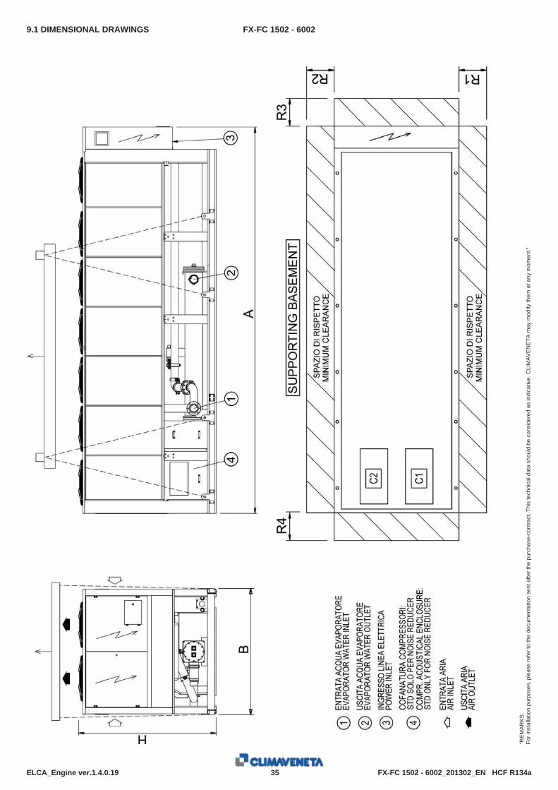
FX-FC 1502 - 6002_201302_EN HCF R134a35ELCA_Engine ver.1.4.0.19
9.1 DIMENSIONAL DRAWINGS
"RE
MA
RK
S:
For i
nsta
llatio
n pu
rpos
es, p
leas
e re
fer t
o th
e do
cum
enta
tion
sent
afte
r the
pur
chas
e-co
ntra
ct. T
his
tech
nica
l dat
a sh
ould
be
cons
ider
ed a
s in
dica
tive.
CLI
MA
VE
NE
TA m
ay m
odify
them
at a
ny m
omen
t."
FX-FC 1502 - 6002
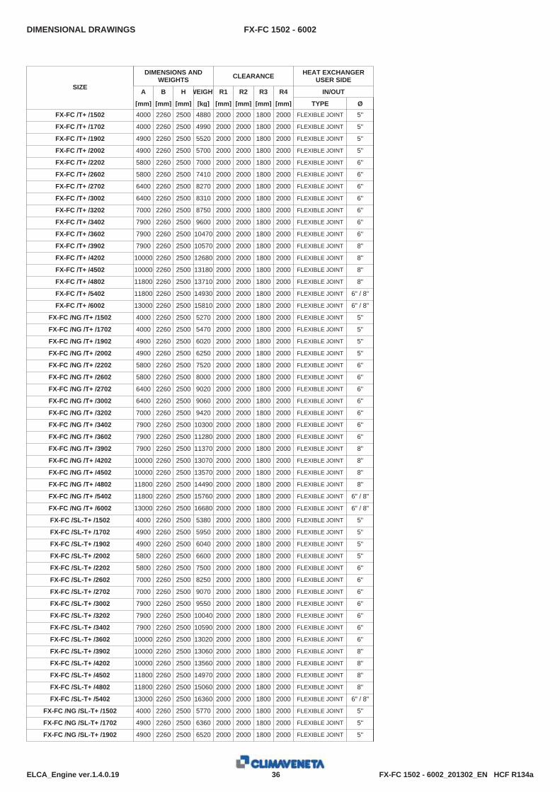
FX-FC 1502 - 6002_201302_EN HCF R134a36ELCA_Engine ver.1.4.0.19
DIMENSIONAL DRAWINGS
DIMENSIONS ANDWEIGHTS CLEARANCE HEAT EXCHANGER
USER SIDE
A B H WEIGHT R1 R2 R3 R4 IN/OUT
[mm] [mm] [mm] [kg] [mm] [mm] [mm] [mm] TYPE Ø
SIZE
FX-FC 1502 - 6002
FX-FC /T+ /1502 4000 2260 2500 4880 2000 2000 1800 2000 FLEXIBLE JOINT 5"
FX-FC /T+ /1702 4000 2260 2500 4990 2000 2000 1800 2000 FLEXIBLE JOINT 5"
FX-FC /T+ /1902 4900 2260 2500 5520 2000 2000 1800 2000 FLEXIBLE JOINT 5"
FX-FC /T+ /2002 4900 2260 2500 5700 2000 2000 1800 2000 FLEXIBLE JOINT 5"
FX-FC /T+ /2202 5800 2260 2500 7000 2000 2000 1800 2000 FLEXIBLE JOINT 6"
FX-FC /T+ /2602 5800 2260 2500 7410 2000 2000 1800 2000 FLEXIBLE JOINT 6"
FX-FC /T+ /2702 6400 2260 2500 8270 2000 2000 1800 2000 FLEXIBLE JOINT 6"
FX-FC /T+ /3002 6400 2260 2500 8310 2000 2000 1800 2000 FLEXIBLE JOINT 6"
FX-FC /T+ /3202 7000 2260 2500 8750 2000 2000 1800 2000 FLEXIBLE JOINT 6"
FX-FC /T+ /3402 7900 2260 2500 9600 2000 2000 1800 2000 FLEXIBLE JOINT 6"
FX-FC /T+ /3602 7900 2260 2500 10470 2000 2000 1800 2000 FLEXIBLE JOINT 6"
FX-FC /T+ /3902 7900 2260 2500 10570 2000 2000 1800 2000 FLEXIBLE JOINT 8"
FX-FC /T+ /4202 10000 2260 2500 12680 2000 2000 1800 2000 FLEXIBLE JOINT 8"
FX-FC /T+ /4502 10000 2260 2500 13180 2000 2000 1800 2000 FLEXIBLE JOINT 8"
FX-FC /T+ /4802 11800 2260 2500 13710 2000 2000 1800 2000 FLEXIBLE JOINT 8"
FX-FC /T+ /5402 11800 2260 2500 14930 2000 2000 1800 2000 FLEXIBLE JOINT 6" / 8"
FX-FC /T+ /6002 13000 2260 2500 15810 2000 2000 1800 2000 FLEXIBLE JOINT 6" / 8"
FX-FC /NG /T+ /1502 4000 2260 2500 5270 2000 2000 1800 2000 FLEXIBLE JOINT 5"
FX-FC /NG /T+ /1702 4000 2260 2500 5470 2000 2000 1800 2000 FLEXIBLE JOINT 5"
FX-FC /NG /T+ /1902 4900 2260 2500 6020 2000 2000 1800 2000 FLEXIBLE JOINT 5"
FX-FC /NG /T+ /2002 4900 2260 2500 6250 2000 2000 1800 2000 FLEXIBLE JOINT 5"
FX-FC /NG /T+ /2202 5800 2260 2500 7520 2000 2000 1800 2000 FLEXIBLE JOINT 6"
FX-FC /NG /T+ /2602 5800 2260 2500 8000 2000 2000 1800 2000 FLEXIBLE JOINT 6"
FX-FC /NG /T+ /2702 6400 2260 2500 9020 2000 2000 1800 2000 FLEXIBLE JOINT 6"
FX-FC /NG /T+ /3002 6400 2260 2500 9060 2000 2000 1800 2000 FLEXIBLE JOINT 6"
FX-FC /NG /T+ /3202 7000 2260 2500 9420 2000 2000 1800 2000 FLEXIBLE JOINT 6"
FX-FC /NG /T+ /3402 7900 2260 2500 10300 2000 2000 1800 2000 FLEXIBLE JOINT 6"
FX-FC /NG /T+ /3602 7900 2260 2500 11280 2000 2000 1800 2000 FLEXIBLE JOINT 6"
FX-FC /NG /T+ /3902 7900 2260 2500 11370 2000 2000 1800 2000 FLEXIBLE JOINT 8"
FX-FC /NG /T+ /4202 10000 2260 2500 13070 2000 2000 1800 2000 FLEXIBLE JOINT 8"
FX-FC /NG /T+ /4502 10000 2260 2500 13570 2000 2000 1800 2000 FLEXIBLE JOINT 8"
FX-FC /NG /T+ /4802 11800 2260 2500 14490 2000 2000 1800 2000 FLEXIBLE JOINT 8"
FX-FC /NG /T+ /5402 11800 2260 2500 15760 2000 2000 1800 2000 FLEXIBLE JOINT 6" / 8"
FX-FC /NG /T+ /6002 13000 2260 2500 16680 2000 2000 1800 2000 FLEXIBLE JOINT 6" / 8"
FX-FC /SL-T+ /1502 4000 2260 2500 5380 2000 2000 1800 2000 FLEXIBLE JOINT 5"
FX-FC /SL-T+ /1702 4900 2260 2500 5950 2000 2000 1800 2000 FLEXIBLE JOINT 5"
FX-FC /SL-T+ /1902 4900 2260 2500 6040 2000 2000 1800 2000 FLEXIBLE JOINT 5"
FX-FC /SL-T+ /2002 5800 2260 2500 6600 2000 2000 1800 2000 FLEXIBLE JOINT 5"
FX-FC /SL-T+ /2202 5800 2260 2500 7500 2000 2000 1800 2000 FLEXIBLE JOINT 6"
FX-FC /SL-T+ /2602 7000 2260 2500 8250 2000 2000 1800 2000 FLEXIBLE JOINT 6"
FX-FC /SL-T+ /2702 7000 2260 2500 9070 2000 2000 1800 2000 FLEXIBLE JOINT 6"
FX-FC /SL-T+ /3002 7900 2260 2500 9550 2000 2000 1800 2000 FLEXIBLE JOINT 6"
FX-FC /SL-T+ /3202 7900 2260 2500 10040 2000 2000 1800 2000 FLEXIBLE JOINT 6"
FX-FC /SL-T+ /3402 7900 2260 2500 10590 2000 2000 1800 2000 FLEXIBLE JOINT 6"
FX-FC /SL-T+ /3602 10000 2260 2500 13020 2000 2000 1800 2000 FLEXIBLE JOINT 6"
FX-FC /SL-T+ /3902 10000 2260 2500 13060 2000 2000 1800 2000 FLEXIBLE JOINT 8"
FX-FC /SL-T+ /4202 10000 2260 2500 13560 2000 2000 1800 2000 FLEXIBLE JOINT 8"
FX-FC /SL-T+ /4502 11800 2260 2500 14970 2000 2000 1800 2000 FLEXIBLE JOINT 8"
FX-FC /SL-T+ /4802 11800 2260 2500 15060 2000 2000 1800 2000 FLEXIBLE JOINT 8"
FX-FC /SL-T+ /5402 13000 2260 2500 16360 2000 2000 1800 2000 FLEXIBLE JOINT 6" / 8"
FX-FC /NG /SL-T+ /1502 4000 2260 2500 5770 2000 2000 1800 2000 FLEXIBLE JOINT 5"
FX-FC /NG /SL-T+ /1702 4900 2260 2500 6360 2000 2000 1800 2000 FLEXIBLE JOINT 5"
FX-FC /NG /SL-T+ /1902 4900 2260 2500 6520 2000 2000 1800 2000 FLEXIBLE JOINT 5"

FX-FC 1502 - 6002_201302_EN HCF R134a37ELCA_Engine ver.1.4.0.19
DIMENSIONAL DRAWINGS
DIMENSIONS ANDWEIGHTS CLEARANCE HEAT EXCHANGER
USER SIDE
A B H WEIGHT R1 R2 R3 R4 IN/OUT
[mm] [mm] [mm] [kg] [mm] [mm] [mm] [mm] TYPE Ø
SIZE
FX-FC 1502 - 6002
FX-FC /NG /SL-T+ /2002 5800 2260 2500 7160 2000 2000 1800 2000 FLEXIBLE JOINT 5"
FX-FC /NG /SL-T+ /2202 5800 2260 2500 8020 2000 2000 1800 2000 FLEXIBLE JOINT 6"
FX-FC /NG /SL-T+ /2602 7000 2260 2500 8890 2000 2000 1800 2000 FLEXIBLE JOINT 6"
FX-FC /NG /SL-T+ /2702 7000 2260 2500 9590 2000 2000 1800 2000 FLEXIBLE JOINT 6"
FX-FC /NG /SL-T+ /3002 7900 2260 2500 10070 2000 2000 1800 2000 FLEXIBLE JOINT 6"
FX-FC /NG /SL-T+ /3202 7900 2260 2500 10570 2000 2000 1800 2000 FLEXIBLE JOINT 6"
FX-FC /NG /SL-T+ /3402 7900 2260 2500 11290 2000 2000 1800 2000 FLEXIBLE JOINT 6"
FX-FC /NG /SL-T+ /3602 10000 2260 2500 13810 2000 2000 1800 2000 FLEXIBLE JOINT 6"
FX-FC /NG /SL-T+ /3902 10000 2260 2500 13850 2000 2000 1800 2000 FLEXIBLE JOINT 8"
FX-FC /NG /SL-T+ /4202 10000 2260 2500 13970 2000 2000 1800 2000 FLEXIBLE JOINT 8"
FX-FC /NG /SL-T+ /4502 11800 2260 2500 15590 2000 2000 1800 2000 FLEXIBLE JOINT 8"
FX-FC /NG /SL-T+ /4802 11800 2260 2500 15680 2000 2000 1800 2000 FLEXIBLE JOINT 8"
FX-FC /NG /SL-T+ /5402 13000 2260 2500 17220 2000 2000 1800 2000 FLEXIBLE JOINT 6" / 8"
LEGEND OF PIPE CONNECTIONSUNI ISO 228/1Pipe threads where pressure-tight joints are not made on the threads - Designation, dimensions and tolerancesUsed terminology:G: Pipe threads where pressure-tight joints are not made on the threadsA: Close tolerance class for external pipe threads where pressure-tight joints are not made on the threadsB: Wider tolerance class for external pipe threads where pressure-tight joints are not made on the threadsInternal threads: G letter followed by thread mark (only tolerance class)External threads: G letter followed by thread mark and by A letter for A class external threads or by B letter for B class external threads.
UNI ISO 7/1Pipe threads where pressure-tight joints are made on the threads - Designation, dimensions and tolerancesUsed terminology:Rp: Internal cylindrical threads where pressure-tight joints are made on the threadsRc: Internal conical threads where pressure-tight joints are made on the threadsR: External conical threads where pressure-tight joints are made on the threadsInternal cylindrical threads: R letter followed by p letterInternal conical threads: R letter followed by c letterExternal conical threads: R letter
Designation Description
Internal cylindrical threads where pressure-tight joints are made on the threads, defined by standardUNI ISO 7/1Conventional ø 1 1/2”
UNI ISO 7/1 - Rp 1 1/2
Internal cylindrical threads where pressure-tight joints are made on the threads, defined by standardUNI ISO 7/1Conventional ø 2 1/2”
UNI ISO 7/1 - Rp 2 1/2
Internal cylindrical threads where pressure-tight joints are made on the threads, defined by standardUNI ISO 7/1Conventional ø 3”
UNI ISO 7/1 - Rp 3
External conical threads where pressure-tight joints are made on the threads, defined by standardUNI ISO 7/1Conventional ø 3”
UNI ISO 7/1 - R 3
Internal cylindrical threads where pressure-tight joints are not made on the threads, defined by standard UNI ISO 228/1Tolerance class B for external threadConventional ø 4”
UNI ISO 228/1 - G 4 B
Flange Nominal Diameter: 80 mmNominal Pressure: 16 barDN 80 PN 16
Notes:Conventional diameter value [in inches] identifies short thread designation, based upon the relative standard.All relative values are defined by standards.As example, here below some values:
UNI ISO 7/1 UNI ISO 228/1
Conventional ø 1" 1"
Pitch 2.309 mm 2.309 mm
External ø 33.249 mm 33.249 mm
Core ø 30.291 mm 30.291 mm
Thread height 1.479 mm 1.479 mm

Via Sarson 57/c36061 Bassano del Grappa (VI)ItalyTel +39 0424 509500Fax +39 0424 [email protected]
www.climaveneta.com
3, Village d’EntreprisesZA de la Couronne des PrésAvenue de la Mauldre78680 EponeFranceTel +33 (0)1 30 95 19 19Fax +33 (0)1 30 95 18 [email protected]
Rhenus Platz, 259439 HolzwickedeGermanyTel +49 2301 91222-0Fax +49 2301 [email protected]
Londres 67, 1° 4°08036 BarcelonaSpainTel +34 963 195 600Fax +34 963 615 [email protected]
88 Bai Yun Rd, Pudong XinghuoNew dev. zone 201419 ShanghaiChinaTel 008 621 575 055 66Fax 008 621 575 057 97
Ul. Sienkiewicza 13A 05-120 LegionowoPolandTel +48 22 766 34 55-57Fax +48 22 784 39 [email protected]
Climate Technologies (P) LTD #3487, 14th Main, HAL 2nd stage Indiranagar, Bangalore 560008 IndiaTel +91-80-42466900 - 949 Fax +91-80-25203540 [email protected]
Highlands Road,Shirley SolihullWest Midlands B90 4NLTel: +44 (0)871 663 0664Fax: +44 (0)871 663 1664Freephone: 0800 801 [email protected]