Fuzzy State Machine Energy Management Strategy for Hybrid...
17
Research Article Fuzzy State Machine Energy Management Strategy for Hybrid Electric UAVs with PV/Fuel Cell/Battery Power System Xiaohui Zhang, Li Liu , and Yueling Dai School of Aerospace Engineering, Beijing Institute of Technology, Beijing 100081, China Correspondence should be addressed to Li Liu; [email protected] Received 1 August 2017; Revised 29 March 2018; Accepted 22 April 2018; Published 2 July 2018 Academic Editor: Paolo Tortora Copyright © 2018 Xiaohui Zhang et al. This is an open access article distributed under the Creative Commons Attribution License, which permits unrestricted use, distribution, and reproduction in any medium, provided the original work is properly cited. Energy management strategies are the key technology for hybrid electric UAVs. This paper proposes a fuzzy state machine (FSM) energy management strategy with an online potential to control the power flow for the hybrid electric UAV which includes the photovoltaic, fuel cell, and battery power sources. The FSM strategy couples the fuzzy logical strategy with a state machine strategy where the fuzzy logical strategy controls the power split between a fuel cell and a battery and the state machine deals with the power flow of photovoltaics and battery. To evaluate the FSM strategy, a simulation platform integrating the hybrid power system model and UAV model is developed with a Matlab/Simulink tool. An existed online thermostat control strategy for the same type of UAV is employed to compare with the proposed strategy based on the developed platform. The energy management process and the state of each power source are analyzed under a given mission scenario. The comparison of the two strategies about the power and energy contribution rates of each power source, the battery state of charge, and the hydrogen consumption is presented. The results indicate that the FSM strategy can satisfy the demand power effectively during the mission and performs better than the thermostat control strategy on power distribution and fuel consumption. 1. Introduction The hybrid electric UAVs in this paper are defined as the full electric UAVs powered by three or more kinds of power sources. In recent years, photovoltaic (PV) panels, fuel cells, and batteries are usually used as the electric propulsion energy. Heavily influenced by the climate, photovoltaic panels generally need to coordinate with batteries to power the UAVs which are called solar-powered UAVs. The rela- tively low energy density of batteries results in the extreme design of the solar-powered UAVs for a lighter structure weight. Fuel cells with higher energy density compared to batteries are potential for longer endurance. Due to soft elec- tric characteristics and relatively slow response, the fuel cells are usually hybrid with batteries in the fuel cell-powered UAVs. Based on the principle of complementary advantages, the hybrid electric power system consisting with the photo- voltaic, fuel cell, and battery power sources for UAVs has been proposed. Different dynamic characteristics of the three kinds of power sources make the hybrid power system more complicated. Thereby, a reasonable and efficient energy man- agement is very important and necessary. Energy management strategies (EMS) determine the power allocation among different power sources and pro- mote the energy efficiency and service life of the hybrid power system. In general, the energy management strategies can be classified into two categories [1]: optimization-based strategies and rule-based strategies. Optimization-based strategies include, dynamic programming (DP) [2–7], Pontryagin’s minimum principle (PMP) [8–10], genetic algorithm (GA) [11], and particle swarm optimization (PSO) [12]. Such optimal strategies usually can get the local or global optimal fuel economy. However, they cannot be used for online management because of the high computa- tional cost. For real-time optimization, some instantaneous optimization strategies are proposed by introducing a cost function that depends only on the present state of the system parameters. Then the concept of energy consumption mini- mization strategy (ECMS) [13–16] and model predictive control (MPC) [17] is introduced for online optimal energy Hindawi International Journal of Aerospace Engineering Volume 2018, Article ID 2852941, 16 pages https://doi.org/10.1155/2018/2852941
Transcript of Fuzzy State Machine Energy Management Strategy for Hybrid...

Research ArticleFuzzy State Machine Energy Management Strategy for HybridElectric UAVs with PV/Fuel Cell/Battery Power System
Xiaohui Zhang, Li Liu , and Yueling Dai
School of Aerospace Engineering, Beijing Institute of Technology, Beijing 100081, China
Correspondence should be addressed to Li Liu; [email protected]
Received 1 August 2017; Revised 29 March 2018; Accepted 22 April 2018; Published 2 July 2018
Academic Editor: Paolo Tortora
Copyright © 2018 Xiaohui Zhang et al. This is an open access article distributed under the Creative Commons Attribution License,which permits unrestricted use, distribution, and reproduction in any medium, provided the original work is properly cited.
Energy management strategies are the key technology for hybrid electric UAVs. This paper proposes a fuzzy state machine (FSM)energy management strategy with an online potential to control the power flow for the hybrid electric UAV which includes thephotovoltaic, fuel cell, and battery power sources. The FSM strategy couples the fuzzy logical strategy with a state machinestrategy where the fuzzy logical strategy controls the power split between a fuel cell and a battery and the state machine dealswith the power flow of photovoltaics and battery. To evaluate the FSM strategy, a simulation platform integrating the hybridpower system model and UAV model is developed with a Matlab/Simulink tool. An existed online thermostat control strategyfor the same type of UAV is employed to compare with the proposed strategy based on the developed platform. The energymanagement process and the state of each power source are analyzed under a given mission scenario. The comparison of thetwo strategies about the power and energy contribution rates of each power source, the battery state of charge, and the hydrogenconsumption is presented. The results indicate that the FSM strategy can satisfy the demand power effectively during themission and performs better than the thermostat control strategy on power distribution and fuel consumption.
1. Introduction
The hybrid electric UAVs in this paper are defined as the fullelectric UAVs powered by three or more kinds of powersources. In recent years, photovoltaic (PV) panels, fuel cells,and batteries are usually used as the electric propulsionenergy. Heavily influenced by the climate, photovoltaicpanels generally need to coordinate with batteries to powerthe UAVs which are called solar-powered UAVs. The rela-tively low energy density of batteries results in the extremedesign of the solar-powered UAVs for a lighter structureweight. Fuel cells with higher energy density compared tobatteries are potential for longer endurance. Due to soft elec-tric characteristics and relatively slow response, the fuel cellsare usually hybrid with batteries in the fuel cell-poweredUAVs. Based on the principle of complementary advantages,the hybrid electric power system consisting with the photo-voltaic, fuel cell, and battery power sources for UAVs hasbeen proposed. Different dynamic characteristics of the threekinds of power sources make the hybrid power system more
complicated. Thereby, a reasonable and efficient energy man-agement is very important and necessary.
Energy management strategies (EMS) determine thepower allocation among different power sources and pro-mote the energy efficiency and service life of the hybridpower system. In general, the energy management strategiescan be classified into two categories [1]: optimization-basedstrategies and rule-based strategies. Optimization-basedstrategies include, dynamic programming (DP) [2–7],Pontryagin’s minimum principle (PMP) [8–10], geneticalgorithm (GA) [11], and particle swarm optimization(PSO) [12]. Such optimal strategies usually can get the localor global optimal fuel economy. However, they cannot beused for online management because of the high computa-tional cost. For real-time optimization, some instantaneousoptimization strategies are proposed by introducing a costfunction that depends only on the present state of the systemparameters. Then the concept of energy consumption mini-mization strategy (ECMS) [13–16] and model predictivecontrol (MPC) [17] is introduced for online optimal energy
HindawiInternational Journal of Aerospace EngineeringVolume 2018, Article ID 2852941, 16 pageshttps://doi.org/10.1155/2018/2852941

management of the hybrid electric vehicles. But for hybridelectric UAVs, they are still on research.
Most online strategies for hybrid electric vehicles andUAVs are based on the rule-based strategies, mainly contain-ing the fuzzy logical control (FCL) [18–24] and the statemachine (SM) [25–29]. These strategies are easily imple-mented online to manage the power flow in the hybrid powersystem, because they can handle complex “black box” prob-lems with low computational cost. Only a few of researcherstried to use the modified dynamic programming called theiterative dynamic programming (IDP) [30, 31] on the hybridelectric UAVs with an internal combustion engine and amotor as the hybrid propulsion system.
For the full electric UAVs with different types of powersources, most researchers only considered two types of powersources, such as a fuel cell and a battery (FC+B) [32–37] orphotovoltaics and a battery (PV+B) [38–44]. Very few ofresearchers concentrated on the hybrid PV/fuel cell/battery(PV+FC+B) [25, 29, 45, 46] power system as they are morecomplicated. So the rule-based strategies were mostly used asthey are more suitable and easier to be implemented online.Li et al. [25, 47] and Lee et al. [28, 46] built a hybrid photo-voltaic/fuel cell/battery power system for UAVs to estimatethe behaviors of each power source using state machinestrategy. However, their studies only developed the hybridpower system model with a given demand power profileand paid little attention to UAV models. The influence ofthe flight dynamic on the hybrid power system and energymanagement was not directly presented and analyzed.Zhang et al. [29] used the simple linear kinematic anddynamic UAV model to investigate the rule-based powertracking strategy for the PV+FC+B hybrid electric UAVs.But the UAV model was constrained in a vertical plane. Nei-ther turns nor banks were considered. The EMS used in thethree studies were all rule-based strategies with simple rulesand limited applicability. To investigate more advancedonline energy management strategies for PV+FC+B, a plat-form that can simulate the real flight of full electric UAVs isneeded and necessary.
In this study, a fuzzy state machine strategy combing thefuzzy logical control with the state machine strategy is pro-posed for PV+FC+B hybrid electric UAVs. To evaluatethe FSM strategy, a closed loop simulation platform inte-grating the hybrid power system model and UAV modelis developed to simulate the real flight conditions. Thedeveloped platform is also verified by comparing withthe gasoline Aerosonde UAV model under a classical mis-sion scenario. Based on such platform, the FSM strategy iscompared with an existing online thermostat control strat-egy which has been implemented online for the same typeof UAV. The comparison of the two strategies about thebattery state of charge, the hydrogen consumption, andthe power and energy contribution rates of each powersource are discussed and analyzed.
The rest of the paper is organized as follows: the fuzzystate machine strategy for hybrid electric UAVs is describedin Section 2, including the hybrid electric UAV frameworkand the details of the fuzzy state machine strategy. Section3 provides the development and integration of the simulation
platform containing the hybrid power system and the UAVmodel. Section 4 presents the simulation results and associ-ated discussion including the comparison of the strategies.Finally, the conclusions are made in Section 5.
2. Fuzzy State Machine Strategy for HybridElectric UAVs
2.1. Sizing of Hybrid Electric UAV. The hybrid electric UAVis constructed by modifying the Aerosonde UAV [37] withthe hybrid power system developed above to replace theGA propulsion system with an internal combustion (IC)engine. The Aerosonde UAV was developed by AerosondePty Ltd. in Australia. To be comparable, the gross weightand aerodynamic configuration of the hybrid electric UAVremain the same with that of the IC engine AerosondeUAV. The configuration sizes and weight breakdowns ofthe Aerosonde UAV and hybrid electric UAV are presentedin Table 1.
As shown in Table 1, the wing area is only 0.55m2 whichlimits the photovoltaic panel available on board. That alsomeans the photovoltaic panel will not be the main powersource. To match the weight, the sizing of the fuel cell andthat of the battery are both limited. The cruise power of theAerosonde UAV determines the fuel cell size. The peakpower demand and the climb phase give a reference for thesizing of the battery.
2.2. Hybrid Electric UAV Framework. The framework of thehybrid electric UAV contains four parts: energy system,energy management system, powertrain system, and air-frame system as illustrated in Figure 1. The energy system,energy management system, and powertrain system consti-tute the hybrid power system for the UAV. The energy sys-tem, including a hydrogen tank, a fuel cell (FC), a battery,photovoltaic panels (PV), and solar irradiance, provides elec-tric energy for the powertrain system through the energymanagement system. The energy control unit (ECU) as thecore processor of energy management system generates thecurrent command for the DCDC converter and the maxi-mum power point tracker (MPPT) based on the system stateand power demand information from the current and voltagesensors, such as Batt CV and Bus CV. The DCDC and MPPTare the actuators to control the output power of FC andPV, respectively, and their output voltages are matchedwith the battery. The solar irradiance on the PV panel sur-face is influenced by the UAV flight state, such as bank,pitch, heading angles, and the latitude. The powertrain sys-tem includes a motor and a propeller to convert the electri-cal energy to mechanical energy and provides thrust andtorque to the airframe system. The motor is controlled bythe autopilot to generate the online demand power for theenergy management system. The autopilot gets the flightstate information from the UAV model and providesdeflection angles for the control surfaces of the UAV. Thisframework can simulate the online situation at every flightmoment with the causal relationship between demand powerand energy management.
2 International Journal of Aerospace Engineering

2.3. Purposes of Energy Management Strategy. The energymanagement strategy (EMS), employed in the ECU module,must have the online potential to control the power flowamong the PV panel, fuel cell, and battery based on theonline situation provided by the hybrid electric UAV plat-form. The EMS also should take advantage of each powersource based on their characteristics and state information.The criteria followed by the EMS are summarized as follows:
(i) The PV panel has the top priority to discharge.Through the MPPT, the PV panel always works atthe maximum power point to provide energy asmuch as possible for flying or charging the battery.
(ii) The battery, cooperating with the PV panel and fuelcell, makes up for surplus demand power. It is also
responsible for sharp fluctuations of the powerdemand and peak power demand. The battery canbe charged by the PV panel and fuel cell with a lim-ited charge rate.
(iii) The fuel cell generally has the lowest output priorityto save the fuel for longer endurance.
(iv) The DC bus demand power is always satisfied by thethree kinds of power sources:
PD = Ppv + Pbatt + P fc, 1
where PD is the DC power demand and Ppv , Pbatt,and P fc are the power extracted from the PV panel,battery, and fuel cell, respectively.
Table 1: Comparison of the Aerosonde UAV and hybrid electric UAV.
Aerosonde UAV Hybrid electric UAV
Configuration size
Length (m) 1.74 Length (m) 1.74
Wingspan (m) 2.87 Wingspan (m) 2.87
Wing area (m2) 0.55 Wing area (m2) 0.55
Weight distribution (kg)
Airframe 3.6 Airframe 3.6
Avionics/payload 2.1 Avionics/payload 2.1
Fuel and fuel tank 5.6 H2 and tank 0.9
Power plant 2.2
BLDC motor 0.4
Electric speed controller 0.04
Propeller 0.06
Fuel cell 3
Li battery 0.9
PV panel 1
DCDC converter 1.2
MPPT 0.1
Flight controller 0.2
Gross weight 13.5 Gross weight 13.5
H2 tank FC DC DC
ECU
MPPT
Batt CV
PV Motor Propeller UAV
AutopilotThrottle
Battery
Bus CV
Ibus, Ubus
Ipv
Ibatt, Ubatt
Ifc
Ppv
Bank, pitch, heading angles,and latitude
Irradiance
Energy system Energy management system Powertrain system Airframe system
Flight stateDeflection
Figure 1: Topology of the hybrid electric UAV framework.
3International Journal of Aerospace Engineering

2.4. Implementation of Fuzzy State Machine. The fuzzy logi-cal control algorithm coupled with the state machine strategyis proposed as the fuzzy state machine (FSM) strategy toenhance the online potential and adaptability of the energymanagement strategy. The implementation process of theFSM strategy is presented in Figure 2. The state of charge(SOC) is from the battery model. The PpvMax from the PVpanel model is the maximum available power of the PV panelon the wing. PD as the demand power of the DC bus can becalculated using
PD = Ibus ⋅Ubus = Ibus ⋅Ubatt, 2
where Ibus is the current through the BLDCmotor andUbus isthe voltage of DC bus. Both of them are measured by the BusCV sensor. Ubus is equal to the battery voltage Ubatt as thebattery is directly connected on the DC bus in parallel.
The FSM strategy used to determine the output of the PVpanel and fuel cell has five states:
State 1: the maximum available power of the PV panel(PpvMax) is higher than the demand power (PD).That means the surplus demand power (Pd) isnegative. The battery with a high state of chargedoes not need to be charged. The PV panel aloneis selected to satisfy the power demand.
State 2: the PV has the ability to satisfy the demandpower. The redundant power from the PV panelfor charging the battery is lower than the maxi-mum charge power (Pchrg). Then the PV paneloutputs its maximum power to meet the demandpower and charge the battery.
State 3: the maximum power from the PV panel ishigher than the summation of demand power(PD) and maximum charge power (Pchrg). Then
the output power of the PV panel equates tothe power summation.
State 4: the PV panel cannot satisfy the power demandalone. To save the fuel, the PV panel gives itsmaximum power. Then the fuzzy logical controlalgorithm is used to decide the desired output offuel cell PF. Considering the constraints of thebattery’s maximum charge rate, the fuel cellpower is modified to be the summation of sur-plus demand power (Pd) and maximum chargepower (Pchrg).
State 5: the PV panel operates with maximum availablepower. And the desired fuel cell power PF isunder the constraint of (3); then the fuel cell willoutput the desired power.
PF + PpvMax − PD < Pchrg 3
From state 1 to state 3, the EMS only uses the statemachine strategy to deal with the output power of thePV panel and battery. The last two states couple withthe fuzzy logical control strategy to control the outputpower of the fuel cell and battery. The PV power and fuelcell power are directly decided using the FSM strategy, butthe battery power is derived automatically based on thepower balance principle.
2.5. Fuzzy Logic Control. The fuzzy logical control has twoinput variables and one output variable, where the surplusdemand power Pd and the state of charge SOC are the inputvariables and the desired fuel cell power is the output vari-able. The battery SOC is categorized into three different sta-tuses called low (L), middle (M), and high (H). Similarly,the Pd is assigned into five regions: very high (VH), high(H), middle (M), low (L), and very low (VL). The fuzzy
Pd = PD – PpvMax
PD PpvMax
Pd > 0No
SOC < SOCH
Ppv = PDPbatt = 0Pfc = 0
No
Yes
Ppv = PpvMaxPbatt = PdPfc = 0
No
|Pd| > Pchrg
Ppv = PD + PchrgPbatt = −Pchrg
Pfc = 0
Yes
Yes
Pb = PF − Pd
Ppv = PpvMaxPbatt = −Pchrg
Pfc = Pchrg + Pd
Yes
Ppv = PpvMaxPbatt = Pd – PF
Pfc = PF
No
SOC
1 2 3 4 5
Pb ≥ Pchrg
PF
Fuzzy logical control
SOC
Pd
PFC
Fuzzy logiccontroller
Figure 2: Fuzzy state machine energy management strategy.
4 International Journal of Aerospace Engineering

output PF is also defined in five statuses just like Pd , such asVH, H, M, L, and VL. The rule base which has 15 rules forthe fuzzy logical control algorithm is given in Table 2. Themembership functions of the Pd, SOC, and PF are given inFigures 3(a)–3(c), respectively. The fuel cell power rule basesurface is presented in Figure 3(d). Mamdani’s fuzzy infer-ence approach is used along with the centroid method fordefuzzification.
The ECU module with the FSM strategy is modeled forthe hybrid power system as shown in Figure 4. The PD is cal-culated using the Ibus and Ubus which are measured at everytime step. The EMS generates the reference current for thefuel cell and PV panel using the output power commandsdividing the DC bus voltage. The battery will compensatethe demand power automatically based on (1).
3. Development of Simulation Platform
3.1. Modeling of the Hybrid Power System
3.1.1. Battery Model. In this study, a lithium-ion battery isused to store energy and quickly respond to demand powerin the hybrid power system. With higher specific power,lithium-ion batteries remedy the limitation of fuel cells. Therechargeable characteristic enhances the utilization efficiencyof the PV panel by storing the surplus solar energy when thepower demand is low. The battery also provides a relativelystable operation voltage on DC bus for the BLDC motor.The dynamic model of the lithium-ion battery from theSimPowerSystems library in Matlab/Simulink is used andpresented in
Discharge Vbatt = E0 − R0 ⋅ ib − KQb
Q − ibtibt + i∗
+ A exp −B ⋅ ibt ,
Charge Vbatt = E0 − R0 ⋅ ib − KQb
ibt − 0 1Qb⋅ i∗
− KQb
Qb − ibt+ A exp −B ⋅ ibt ,
4
where Vbatt is the battery voltage, E0 is the constant voltage, Kis the polarization constant, Qb is the maximum batterycapacity, ibt = ibdt is the extracted capacity (Ah), A is theexponential voltage, B is the exponential capacity, R0 is theinternal resistance, ib is the battery current, and i∗ is the fil-tered current. The state of charge (SOC) presents the batterystate limited within [0, 1], where 1 indicates full charge and 0means empty. The SOC is expressed in
SOC = 1 −t0ibdt
Qb5
3.1.2. Solar Irradiance and PV Panel Model. As the UAV isflying, the solar irradiance on the PV panel varies with themaneuver. The PV panel surface is assumed to be flat. Theincidence angle depends on the azimuth and zenith anglesof the sun. The Euler angles and latitude decide the anglebetween sun rays and the PV panel. According to [48], theazimuth and zenith angles are described in
sin αe = sin nlat sin δ + cos nlat cos δ cos ω t ,
sin αs =cos δ sin ω t
cos αe,
δ = 0 4093sin2π 284 + n
365,
ω t = 0 2618 × 12 − tlocal ,
6
where αe and αs are the azimuth and zenith angles of thesun, respectively; nlat is the latitude of the UAV; δ is thedeclination angle of the sun; ω t is the hour of the sun;tlocal is the current hour of the day; and n is the date inthe year.
The expression of the incidence angle i is calculatedby [49]
cos i = SA ⋅ Z , 7
where SA is the unit vector to the sun in the earth-fixed
frame and Z is the aircraft-fixed vertical axis. The unit vectorto the sun in the aircraft-fixed frame can be expressed in
SA = R1 ϕ R2 θ R3 ψ ⋅ SE, 8
where the vector SE is the unit vector to the sun in the earth-fixed frame defined in
SE = cos αe cos αs cos αe sin αs sin αeT 9
and R1, R2, and R3 are rotation matrices about the bank angleϕ, pitch angle θ, and heading angle ψ, respectively. If the effi-ciency of the photovoltaic panel is assumed as a constant, thepower of the PV panel is given in
Ppv = ηmpptηpvQirrS cos i , 10
where ηpv is the efficiency of the photovoltaic panel, Qirr isthe solar irradiance, S is the area of the PV panel on the wingsurface, i is the incidence angle of sun rays, and ηmppt is theefficiency of the MPPT. So the PpvMax is equal to Ppv for thesimplification of the MPPT model.
3.1.3. Fuel Cell Model. The proton exchange membrane fuelcell (PEMFC) with high energy density and low operatingtemperature is suitable to power the electric UAV for longendurance. The dynamic fuel cell model used here is also
Table 2: Rule base of fuzzy logical control.
PFPd
VH H M L VL
SOC
L VH VH H M L
M VH H M L L
H H M L VL VL
5International Journal of Aerospace Engineering

from the SimPowerSystems library, but the model parame-ters are from our experiment. The fuel cell output voltageV fc is decided by the number of cells (ncell) in series and everysingle cell voltage (Vcell) as shown in
V fc = ncellVcell 11
The air and hydrogen flow rates are calculated by
UO2=
60000RTNifczFPairV lpm air O2%
,
UH2=
60000RTNifczFPH2
V lpm H2H2%
,12
where UO2and UH2
are the rates of utilizations of oxygenand hydrogen, respectively, R is the universal gas constant
1 VL L M H VH
0.5
00 200 400 600 800
Input variable “Pd”1000
(a) Surplus demand power membership functions
L M H
0 0.2 0.4 0.6Input variable “SOC”
0.8 1
1
0.5
0
(b) Battery SOC membership functions
VL L M H VH
0 200 300100 400 600500Output variable “PF”
1
0.5
0
(c) Fuel cell power membership functions
600
400
200
PF
5001000
PdSOC
10.5
0 0
(d) Fuel cell-desired power rule base surface
Figure 3: Membership functions and rule base surface.
×PD
Fuel cell current control algorithm
PV panel powered only
Pchrg
Pchrg
SOC < SOCH
PpvMax > PD
PpvMax > PD
PpvMax > PD
Ppv = Pchrg + PD
1
0
0
0
Pd
FLCPF
Pb
Pchrg
−−1
0
+−
+
+ ÷
× lfcPfc
PpvMax > PD
PpvMax ≥ PD: Pfc = 0
PpvMax > PD : Ppv = PD + Pb
PpvMax ≤ PD: Ppv = PpvMax: Ppv = PD
PpvMax < PD: Pfc = PfcPfc = Pchrg + Pc
1Ibus
Ubus
PpvMax
SOC
2
4
3
1+
0.01
× +
+
×
2Ipv÷
Figure 4: Topology of ECU simulation module.
6 International Journal of Aerospace Engineering

8.3145 J/(mol·K), F is the Faraday constant 96,485As/mol,O2% is the percentage of oxygen in oxidant, T is the temper-ature, Pair is the absolute supply pressure of air, V lpm air is theair flow rate, V lpm H2
is the H2 flow rate, H2% is the percent-age of hydrogen in fuel, PH2
is the absolute supply pressure offuel, and z is the number of moving electrons. The H2 gas isstored in a carbon fiber tank with a maximum pressure of20MPa. The state of pressure (SOP) is defined as the rem-nant H2 pressure in a tank can be calculated in
SOP = P0 −1Vol
t
0V lpm t dt, 13
where P0 is the initial pressure of H2 in the tank, Vol is thetank volume, and V lpm t is the H2 flow rate. When SOP isless than low pressure Plow , the fuel cell will stop working.
3.1.4. Powertrain Model. The powertrain contains a BLDCmotor and a fixed pitch propeller. The motor model ispresented in
Im =Um −Ω/kv
rm,
Mm = Im − I030πkv
,14
where Im and Um are the terminal voltage and current of theelectric motor, respectively, rm is the terminal resistance, kv isthe rotation speed constant, Ω is the rotation speed, Mm isthe torque produced by the motor, and I0 is the idle currentwithout load.
The fixed pitch propeller is modeled as presented in
Fp =4π2 ρR4Ω2CT,
Mp =4π3 ρR5Ω2CP,
15
where Fp and Mp are the thrust and torque of the propeller,respectively, ρ is the air density, R is the radius of the propel-ler, Ω is also the rotation speed, and CT and CP are the thrustand power coefficients, respectively. When the motor drivesthe propeller, the dynamic model of the powertrain is givenin (16), where J is the rotational inertia of the motor shaftand propeller.
Mm −Mp = JΩ 16
The DCDC converter is modeled in
UoutIout = ηdcU inIin, 17
where the Uout and Iout are the output voltage and current,U in and Iin are the input voltage and current, and ηdc is theefficiency of the DCDC converter.
3.1.5. Integration of the Hybrid Power System. By integratingthese models presented above, the topology of the hybridpower system model is shown in Figure 5. The fuel cell cur-rent is controlled by the DCDC converter. The simple DCDCconverter and BLDC motor simulation models are shown inFigure 6.
3.2. Closed-Loop Simulation Platform of Hybrid Electric UAV.The closed-loop simulation platform of a hybrid electricUAV is developed with the AeroSim Blockset library inMatlab/Simulink as shown in Figure 7. The general aviation(GA) engine propulsion system is replaced by the developedhybrid power system as shown in Figure 5. Except for the
m
H2 Air
Continuous
Ipm
Low2
0.5
Bar
L150
BarH2 in tank
[SOC]
[Ubatt]
<SOC (%)>
<Voltage (%)>
Li battery
Lat
Roll
Yaw
Pith
IrradianceTemp
PV panel with MPPTYaw
Pitch
Roll
Lat6
7
8
4
[lsc] lsc+
lr
m [Ppv]<Ppv>
T9
lrr
Fuel cell stack DC converter
1Thr
Thr
Omega/rad/s
Mmot
Curr
2
3
Airspeed
rho
BLDC motor
EMS
[Ifc]
[lsc]
Ifc
Ifc
Ipv
Ibus
SOC
Ubus
PpvMax
[SOC]
[Ubatt]
[Ppv]
lsc
[lfc]
Vol
Pres0
+
m
−
−
−
−
+
+
−
+
+
rho
Airspeed Mprop
PropCoeffPropCoeff
4
0
Jeng
JpropM/J
Reset5
3
2Mprop
Omega
1s
Fprop
Fixed-pitch propeller
0
powergui
Fprop1
Omega
+
+
×
÷++
Figure 5: Topology of the hybrid power system.
7International Journal of Aerospace Engineering

UAV model, the platform also contains the aircraft controlmodule and flight planner module. Using the great circlenavigation method, the flight planner module calculates thenecessary bearing/yaw adjustment, target altitude, and targetairspeed based on the waypoint information including thelatitude, longitude, altitude, and airspeed. Then the UAV willtrace the waypoints correctly. The aircraft control moduleuses the current and target position, altitude, and airspeedinformation to generate the throttle signal, rudder deflection
angle, aileron deflection angle, and elevator deflection angle.The classical PID control algorithm is used in this module.The throttle range is between 0 and 1. The details of the auto-pilot model are given in [50].
3.3. Simulation Parameters. The mission scenario includesbasic UAV operations such as climb, cruise, descent, andloiter. The waypoint information is listed in Table 3[50]. It is assumed that the takeoff time is 12:00 at noon
+ DC out
3
Efficiency
0.9
×
×
÷
−
−
+
s
+V
2 10-40
lfc_cmd
s
1+ln
−ln
+
+
R
V
−−
+
−
− DC out4
+
(a) DCDC converter
Omega / rad/s1 30/pi 0
2l0
30/pi 1
2Curr
Mmot>
kv420
rm0.02
s
2
2�r
1
10.01s+1
+
−
V+−
×
÷
×÷
×÷
×
+
−
+−
+−
l
(b) Electric motor
Figure 6: Topology of the DCDC converter and electric motor.
Aerosonde UAV model(Body-frame EOM)
�rottle setting Current roll angle
Bearing adjustment
Current altittudeRudder deflection
Aileron deflection
Target airspeed
Current airspeed (Airspeed)
(Altitude)
(Altitude)
(Longitude)
(Latitude)
Autopilot
B/Yaw AdjWind corrections
Current latitude
Current longitude
Current altitude
Current airspeedTarget airspeed
Flight planner module
Target altitude
Elevator deflection
Aircra� control module
Target altitude
0Flap
Controls
StatesSensors
Veiw
Mach
Ang Acc
Euler
AeroCoeff
PropCoeff
WindsWinds0 0 0
Mass
ECEF
AGLRSTReset
0
R EarthAConGnd STOP
R2D
R2DR2D Airspeed
Sideslip
AOA
Bank angle
Pitch angle
Yaw angleAircra� states
Engine speedFuel massAltitudeLongitudeLatitude
Quarternion eyQuarternion exQuarternion e0Yaw rate rPitch rate q
Lon
Lat
Alt
Drawing
(Latitude)
(Longitude)
(Altitude)
Roll rate pGround speed z-axisGround speed y-axisGround speed x-axis
Quarternion ez
(Airspeed)
STOP
R2D
R2DR2D
(Airspeed)
Figure 7: Closed loop simulation platform of the hybrid electric Aerosonde UAV.
8 International Journal of Aerospace Engineering

on the summer solstice and the maximum irradiance ofthe day is 1200W/m2.
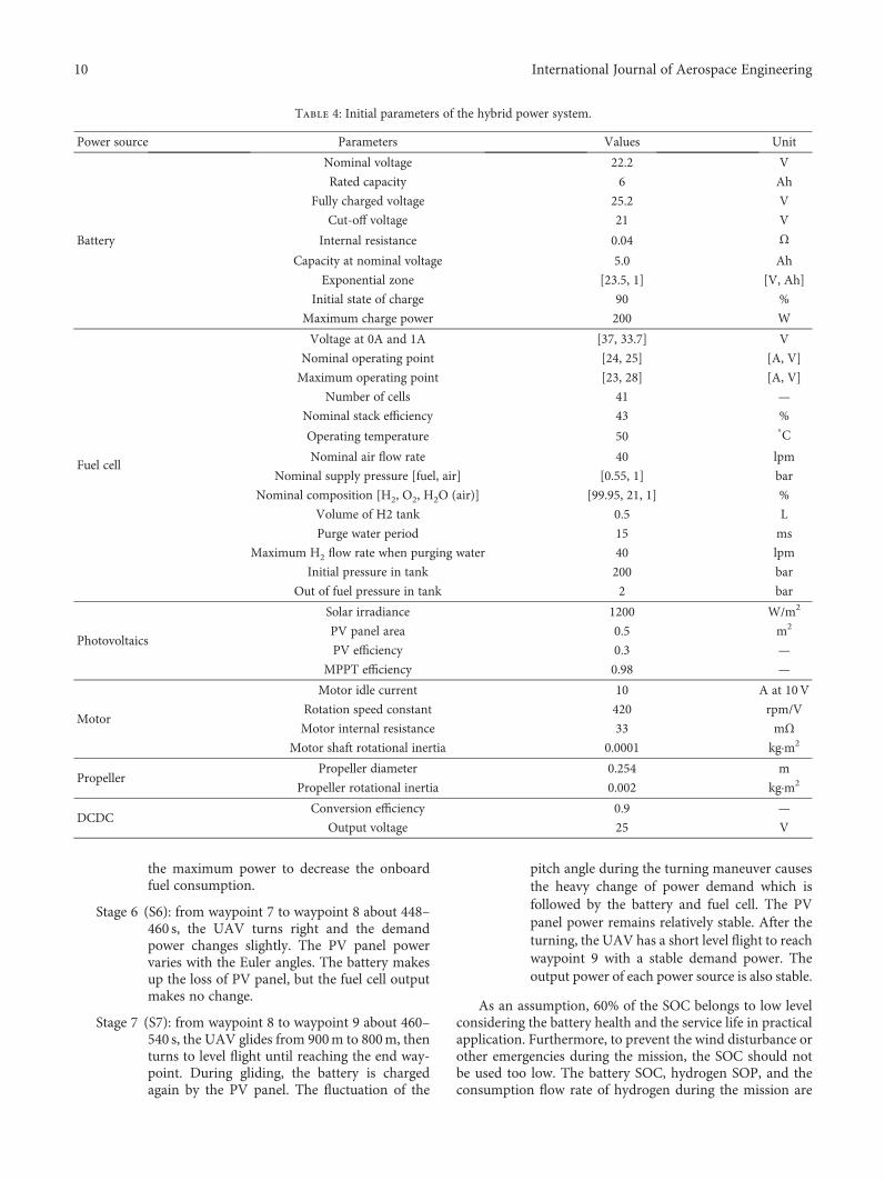
The initial parameters of the hybrid power system arelisted in Table 4 which includes the parameters of the battery,fuel cell, H2 tank, photovoltaic panel, motor, propeller, andDCDC converter. The propeller is still the same as the origi-nal Aerosonde UAV. The CT and CP of the propeller aregiven in [50]. The simulation used the ode14x solver withthe fixed-step, and the step size is 0.1 s.
4. Results and Discussion
4.1. Hybrid Electric UAV Model Validation. The hybrid elec-tric UAV model is verified by comparison with the originalgasoline Aerosonde UAV in Matlab/Simulink under thesame mission scenario. The comparison results are presentedin Figures 8 and 9. The top and side views of flight pathsagree with each other for the two UAVs. The bank and head-ing angles of the UAVs are the same with each other. That isalso the reason for the coincidence of top view paths.Figure 9(c) shows the pitch angles of the two UAVs are a littledifferent during the transition from descent to level flight.That results in the difference of the transitional path as seenin Figure 8(b). The comparison of the two UAVs proves thatthe hybrid electric UAV model almost has the same perfor-mance with the original Aerosonde.
4.2. Energy Management Analysis. For the electric UAV, theflight height varying with time is presented in Figure 10.During the mission, the energy management system withthe proposed FMS strategy calculates the demand powerand distributes the power among the three power sourcesas shown in Figure 11. Based on the mission scenario, theenergy management process can be separated into sevenstages from S1 to S7:
Stage 1 (S1): from waypoint 1 to waypoint 2 about 0–98 s, the UAV climbs from 800m to 900m thenturns to level flight. During the climb, thedemand power is about 1100W much higher
than the maximum power of the PV panel whichhas the highest priority to provide power. Thesurplus demand power is split between the bat-tery and the fuel cell by the fuzzy logical controlstrategy. Since the initial SOC is high, the batterygives more power than the fuel cell. Whenreaching target altitude 900m, the UAV turnsto level flight, the demand power down to620W; the output power of the PV panel showsslight variations due to the decrease of the pitchangle. The output powers of the battery and fuelcell both fall down.
Stage 2 (S2): from waypoint 2 to waypoint 3 about 98–126 s, the UAV turns left and the bank angle sig-nificant changes at about 100 s. The powerdemand also arises a sudden change which isfollowed by the battery and fuel cell successfully.The bank angle results in a serious power loss ofthe PV panel.
Stage 3 (S3): from waypoint 3 to waypoint 4 about 126–265 s, the UAV changes from descent to levelflight. In descent, it glides without any powerin need. The power of the PV panel is higherthan the demand power which means the PVpanel can save the surplus energy by chargingthe battery. When approaching the target alti-tude 750m, the UAV turns to level flight. Thepitch angle oscillates heavily. The demandpower also waves strongly. The outputs of thebattery and fuel cell following the demandpower present serious fluctuations, but thepower of the PV panel presents light change.Then the UAV gives a long time stable levelflight until reaching waypoint 4. Each powersource provides a constant output during thelevel flight.
Stage 4 (S4): from waypoint 4 to waypoint 6 about 265–290 s, the UAV turns right three times in a shorttime which causes the variations of the demandpower. The PV panel power fluctuates with thebank angle and heading angle. The surplusdemand power is followed by the battery andfuel cell.
Stage 5 (S5): from waypoint 6 to waypoint 7 about 290–448 s, the UAV changes from climb to levelflight. At the beginning of the climb, thedemand power presents a sharp increase whichis tracked by the battery as the demand poweris much higher than the maximum power ofthe fuel cell and PV panel. During this climb,the demand power is up to 1100W again; thefuel cell operates near the maximum powerpoint, until the UAV is arriving at the targetaltitude 900m. Then the UAV turns to levelflight and the demand power decreases to620W, the output power of battery and fuel cellboth decrease, and the PV panel still provides
Table 3: Waypoint information of mission scenario.
Waypoint Latitude LongitudeAltitude(m)
Airspeed(m/s)
WP1(origin)
26°34′51′′S 151°50′28′′E 800 20
WP2 26°33′58′′S 151°51′10′′E 900 20
WP3 26°34′08′′S 151°51′25′′E 900 20
WP4 26°34′18′′S 151°53′13′′E 750 30
WP5 26°34′08′′S 151°53′18′′E 750 20
WP6 26°33′59′′S 151°53′13′′E 750 20
WP7 26°34′08′′S 151°53′25′′E 900 20
WP8 26°34′14′′S 151°53′17′′E 900 20
WP9 (end) 26°34′51′′S 151°50′28′′E 800 30
9International Journal of Aerospace Engineering
the maximum power to decrease the onboardfuel consumption.
Stage 6 (S6): from waypoint 7 to waypoint 8 about 448–460 s, the UAV turns right and the demandpower changes slightly. The PV panel powervaries with the Euler angles. The battery makesup the loss of PV panel, but the fuel cell outputmakes no change.
Stage 7 (S7): from waypoint 8 to waypoint 9 about 460–540 s, the UAV glides from 900m to 800m, thenturns to level flight until reaching the end way-point. During gliding, the battery is chargedagain by the PV panel. The fluctuation of the
pitch angle during the turning maneuver causesthe heavy change of power demand which isfollowed by the battery and fuel cell. The PVpanel power remains relatively stable. After theturning, the UAV has a short level flight to reachwaypoint 9 with a stable demand power. Theoutput power of each power source is also stable.
As an assumption, 60% of the SOC belongs to low levelconsidering the battery health and the service life in practicalapplication. Furthermore, to prevent the wind disturbance orother emergencies during the mission, the SOC should notbe used too low. The battery SOC, hydrogen SOP, and theconsumption flow rate of hydrogen during the mission are
Table 4: Initial parameters of the hybrid power system.
Power source Parameters Values Unit
Battery
Nominal voltage 22.2 V
Rated capacity 6 Ah
Fully charged voltage 25.2 V
Cut-off voltage 21 V
Internal resistance 0.04 ΩCapacity at nominal voltage 5.0 Ah
Exponential zone [23.5, 1] [V, Ah]
Initial state of charge 90 %
Maximum charge power 200 W
Fuel cell
Voltage at 0A and 1A [37, 33.7] V
Nominal operating point [24, 25] [A, V]
Maximum operating point [23, 28] [A, V]
Number of cells 41 —
Nominal stack efficiency 43 %
Operating temperature 50°C
Nominal air flow rate 40 lpm
Nominal supply pressure [fuel, air] [0.55, 1] bar
Nominal composition [H2, O2, H2O (air)] [99.95, 21, 1] %
Volume of H2 tank 0.5 L
Purge water period 15 ms
Maximum H2 flow rate when purging water 40 lpm
Initial pressure in tank 200 bar
Out of fuel pressure in tank 2 bar
Photovoltaics
Solar irradiance 1200 W/m2
PV panel area 0.5 m2
PV efficiency 0.3 —
MPPT efficiency 0.98 —
Motor
Motor idle current 10 A at 10V
Rotation speed constant 420 rpm/V
Motor internal resistance 33 mΩMotor shaft rotational inertia 0.0001 kg·m2
PropellerPropeller diameter 0.254 m
Propeller rotational inertia 0.002 kg·m2
DCDCConversion efficiency 0.9 —
Output voltage 25 V
10 International Journal of Aerospace Engineering

shown in Figure 12(a). The SOC varies from 90% to 65%keeping in the ideal operating range. As the SOC decreases,the output power of the fuel cell is higher in the second climb
than that in the first climb. The hydrogen in the tank is con-sumed from 200 bar down to 70 bar. Except for purging waterat every 15 s, the hydrogen flow rate varies with the fuel cell
2001(9)
8
2
3(7)4
5
6
Aerosonde UAVHybrid electric UAV
−200
−600
−1000
−1400
−1800−1000 0
Nor
th (m
)
1000 2000East (m)
3000 4000 5000
(a) Top view of flight path
920
880
840
800
760
720
1(9)
2 8 3(7)
5
4(6)
Alti
tude
(m)
−1000 0 1000 2000East (m)
3000 4000 5000
Aerosonde UAVHybrid electric UAV
(b) Side view of flight path
Figure 8: Comparison of the flight path.
40
20
−0
−20
−40
−600 50
Bank
angl
e (de
g)
100 150 200 250 300 350Time (s)
Aerosonde UAVHybrid electric UAV
400 450 500 550 600
(a) Bank angle
Hea
ding
angl
e (de
g)
Aerosonde UAVHybrid electric UAV
360300240180120
600
0 50 100 150 200 250 300 350 400Time (s)
450 500 550 600
(b) Heading angle
Pitc
h an
gle (
deg)
20
0
−20
Aerosonde UAVHybrid electric UAV
0 50 100 150 200 250 300 350Time (s)
400 450 500 550 600
(c) Pitch angle
Figure 9: Comparison of the attitude angles.
800
850
800H (m
)
750
0 50 100 150 200 250 300Time (s)
350 400 450 500 550 600
1S1 S2 S3
4 5 6
S4 S5 S6 S7 9
8732
Figure 10: Height and velocity of the hybrid electric UAV.
11International Journal of Aerospace Engineering

power. About 35 g hydrogen is consumed in the mission. Theirradiance on the PV panel surface and the output of PVpanel are influenced by the flight attitude angles, especiallythe bank angle in this mission as shown in Figure 12(b).
4.3. Comparison with Thermostat Control Strategy. To becompared with the proposed FSM strategy for the same mis-sion, a constrained thermostat control (CTC) strategy pro-posed by Lee et al. [28] for the hybrid electric UAV usingthe same power sources is illustrated in Figure 13. The CTCmaintains a certain SOC during the flight process in orderto cope with the influence of the weather on the PV panel.The CTC also takes the PV panel as the highest priority out-put. The surplus power of the PV panel is used to charge thebattery. When the SOC is higher than SOCL, the battery isused to make up the insufficient power of the PV panel andfuel cell during high power demand.
The power contribution rate (PCR) and energy contribu-tion rate (ECR), used to analyze the contribution of eachpower source, are defined as the output power and energyof each power source divided by the total consumed powerand energy, respectively.
0 50 100 150 200 250 300 350 400 450 500 550 600
0 50 100 150 200 250 300 350 400 450 500 550 600
0 50 100 150 200 250 300 350 400 450 500 550 600
0 50 100 150 200 250 300Time (s)
350 400 450 500 550 600
−200
300
200
100
0
600
300
0Pfc
(W)
Ppv
(W)
Pba
tt (W
)P
D (W
)
800
1400700
0
Figure 11: Demand power and power distribution.
100
200
5025
0
150100
50
8060
0 100 200 300 400 500 600
0 100 200 300 400 500 600
0 100 200 300 400 500 600Times (s)
SOC
(%)
SOP
(bar
)H
2 (lp
m)
(a) State of the battery and fuel cell
0
50
1200
180120
600P
PV (W
)Ir
r (W
/m2 )
Bank
(deg
)
800400
0
0−50
100 200 300
Times (s)
400 500 600
0 100 200 300 400 500 600
0 100 200 300 400 500 600
(b) Irradiance and power varying with bank angle
Figure 12: State of each power source.
PD = Ppv + Pfc + Pbatt
SOC ≥ SOCH &PD ≤ PpvMax
PD ≥ PpvMax+ PfcMax
PD ≤ PpvMax
SOC ≤ SOCL
Yes
Yes
Yes
Yes
No
No
No
Ppv = PpvMax
Ppv = PDPfc = 0Pbatt = 0
Pfc = PfcMax
Pfc = PfcMax
Pbatt = PD − PpvMax − PfcMax
Pbatt = −(PpvMax + PfcMax − PD)
Pfc = 0Pbatt = −(PpvMax − PD)
Pfc = PD – Ppv + Pchrg×(SOCL − SOC)Pbatt = PD − PpvMax − Pfc
No
Figure 13: Diagram of the constrained thermostat control strategy.
12 International Journal of Aerospace Engineering

The PCR and ECR of each power source for the FSM andCTC strategies are seen in Figure 14. Figure 14(a) shows thatthe PCRs of the PV panel in both strategies are almost thesame. When the demand power is zero, the PCRs of the bat-tery, PV panel, and fuel cell for both strategies are the same,and they are −100%, 100%, and 0%, respectively. But thePCRs of the battery and the fuel cell for the two strategiesare different. The PCR of the battery for FSM is higher thanthat for CTC during most time of the mission. Contrarily,the PCR of the fuel cell for FSM is lower than that for CTC.
For the battery and the fuel cell in the two strategies,different PCRs result in different ECRs as shown inFigure 14(b). In the FSM test, the ECRs of the PV panel, bat-tery, and fuel cell are 18%, 31%, and 51%, respectively. But inthe CTC test, they are 17%, 15%, and 67%, respectively. Theenergies from the PV panel in the two strategy tests arealmost the same. But the energy from the battery for FSMis more than twice as much as that for CTC. The energy fromthe fuel cell for CTC is obviously more than that for FSM.
The state variations of the battery and the hydrogen inthe two strategy tests are shown in Table 5. With the sameinitial SOC and SOP, the battery is used more efficiently inthe FSM test. Compared with the consumed hydrogen underthe CTC strategy, less hydrogen is consumed for the FSMstrategy. The amount of saved hydrogen fuel is 26.7% underthe FSM strategy.
5. Conclusions
In this paper, a fuzzy state machine strategy with anonline potential is proposed for PV+FC+B hybrid electricUAVs. A simulation platform integrating the hybrid power
system model and UAV model is developed with aMatlab/Simulink tool. Based on such platform, the proposedFSM strategy is verified and compared with an existed onlinethermostat control strategy. The results of the study are sum-marized as follows:
(1) By comparison with the Aerosonde UAV, it indicatesthat the developed platform is reasonable and accept-able for energy management researches. The plat-form with a fixed-step size can generate the demandpower at every time step for energy managementstrategies to simulate the online situation.
(2) Under the FSM strategy, the PV panel generally pro-vides its maximum available power which is onlyinfluenced by the flight attitude, especially the bankangle for this mission. The battery is charged by thePV panel during descent stages, and it can compen-sate for the surplus demand power or peak powerdemand. The fuel cell can automatically regulate itsoutput power based on the demand power and bat-tery SOC.
(3) In both strategies, the ECRs show that the fuel cell asthe main power source provides the most energy forthe propulsion system and the PV panel as the addi-tional power source outputs the least energy. The bat-tery as the assist power source responses to highdemand power and can be charged at low powerdemand.
(4) The contribution of the PV panel for the FSM strat-egy is almost the same with that for the CTC strategy.
FSMCTC
−1
0
1
1
0.5
0
1
0.5
00 100 200 300 400 500 600
Time (s)
PCR f
cPC
R PV
PCR b
att
(a) Power contribution rate
FSMCTC
Photovoltaic
70
60
50
40
30
20
10
0
ECR
(%)
Battery Fuel cell
(b) Energy contribution rate
Figure 14: Power and energy contribution rates of each power source.
Table 5: Comparison of the state of the battery and fuel cell between FSM and CTC.
SOC (%) SOP (bar) Consumed H2(L)Initial Final Consumed Initial Final Consumed
FSM 90 65 25 200 70 130 66
CTC 90 77 13 200 19 181 90
13International Journal of Aerospace Engineering

The FSM strategy prefers to consume more batteryenergy than CTC does. Compared with the CTCstrategy, less fuel cell energy is consumed in theFSM strategy which leads to 26.7% of the hydrogenfuel saved.
Nomenclature
αe: Azimuth angle of the sun (rad)αs: Zenith angle of the sun (rad)δ: Declination angle of sthe un (rad)ηdc: Efficiency of the DCDC converterηmppt: Efficiency of the MPPTηpv : Efficiency of the photovoltaic panelρ: Air density (kg/m3)ϕ: Bank angle (rad)ω t : Hour of the sun (rad)Θ: Pitch angle (rad)ψ: Heading angle (rad)Ω: Rotation speed (r/min)A: Exponential voltage (V)B: Exponential capacity (Ah)CP: Power coefficient of the propellerCT: Thrust coefficient of the propellerE0: Constant voltageF: Faraday constantFp: Thrust of the propeller (N)H2%: Percentage of hydrogen in fueli: Incidence angle (rad)ib: Battery current (A)i∗: Filtered current (A)I0: Idle current without load (A)Ibatt: Current of the battery in simulation (A)Ibus: Current of bus (A)Ifc: Current command of fuel cell (A)Iin: Input current of DCDC (A)Im: Terminal current of the electric motor (A)Iout: Output current of DCDC (A)Ipv: Current command of photovoltaics (A)J: Rotational inertia of the motor shaft and propeller
(m4)K: Polarization constantkv: Rotation speed constantMm: Torque produced by motor (N·m)Mp: Torque of the propeller (N·m)n: Date in the year, n = 1 when the date is the 1st of
Januaryncell: Number of cellsP0: Initial pressure of H2 (bar)Pair: Absolute supply pressure of air (atm)Pb: Desired output of battery (W)Pbatt: Power of battery (W)Pchrg: Maximum charge power (W)Pd: Means the surplus demand power (W)PD: DC power demand (W)PF: Desired output of fuel cell (W)Pfc: Power of fuel cell (W)PH2
: Absolute supply pressure of fuel (atm)
Plow: Low pressure (atm)Ppv: Power of photovoltaics (W)PpvMax: Maximum available power of PV (W)Qb: Maximum battery capacity (Ah)Qirr: Solar irradiance (W/m2)Rp: Radius of the propeller (m)R: Universal gas constantR0: Internal resistance of battery (Ω)R1: Rotation matrices about the bank angle (ϕ)R2: Rotation matrices about the pitch angle (θ)R3: Rotation matrices about the heading angle (ψ)rm: Terminal resistance of electric motor (Ω)S: Area of the PV panel on the wing surface (m2)
SA : Unit vector to the sun in the earth-fixed frame
SOC: State of chargeSOP: State of pressure (bar)T: Temperature of fuel cell (K)tlocal: Current hour of the day (hour)UAV: Unmanned aerial vehicleUbatt: Voltage of battery (V)Ubus: Voltage of bus (V)UH2
: Rates of utilizations of hydrogenUin: Input voltage of DCDC (V)Um: Terminal voltage of the electric motor (V)Uout: Output voltage of DCDC (V)UO2
: Rates of utilizations of oxygenV cell: Single-cell voltage of fuel cell (V)Vlpm(air): Air flow rate (L/min)Vlpm(H2): H2 flow rate (L/min)Vlpm(t): H2 flow rate (L/min)Z: Number of moving electrons.
Conflicts of Interest
The authors declare that there is no conflict of interestregarding the publication of this paper.
References
[1] S. Caux, W. Hankache, M. Fadel, and D. Hissel, “On-line fuzzyenergy management for hybrid fuel cell systems,” Interna-tional Journal of Hydrogen Energy, vol. 35, no. 5, pp. 2134–2143, 2010.
[2] H. Mosbech, “Optimal control of hybrid vehicle,” in Proceed-ings of the International Symposium Automotive Technologyand Automation, pp. 303–320, Torino, 1980.
[3] V. I. M. Oprean, N. Mocanu, S. Beloiu, and C. Stanciu,“Dynamic programming applied to hybrid vehicle control,”in Proceedings of the International Conference on ElectricDrives (ICED ’88), pp. D2/10/1–D2/10/20, Romania, 1988.
[4] D. Ambuhl, Energy Management Strategies for Hybrid ElectricVehicles, PhD dissertation, ETH ZURICH, Zurich, 2009.
[5] O. Sundström, D. Ambühl, and L. Guzzella, “On implementa-tion of dynamic programming for optimal control problemswith final state constraints,” Oil & Gas Science and Technology,vol. 65, no. 1, pp. 91–102, 2010.
[6] P. Elbert, S. Ebbesen, and L. Guzzella, “Implementation ofdynamic programming for n-dimensional optimal control
14 International Journal of Aerospace Engineering

problems with final state constraints,” IEEE Transactions onControl Systems Technology, vol. 21, no. 3, pp. 924–931, 2013.
[7] M. Ansarey, M. Shariat Panahi, H. Ziarati, and M. Mahjoob,“Optimal energy management in a dual-storage fuel-cellhybrid vehicle using multi-dimensional dynamic program-ming,” Journal of Power Sources, vol. 250, pp. 359–371, 2014.
[8] N. Kim, S. Cha, and H. Peng, “Optimal control of hybrid elec-tric vehicles based on Pontryagin’s minimum principle,” IEEETransactions on Control Systems Technology, vol. 19, no. 5,pp. 1279–1287, 2011.
[9] C. H. Zheng, N. W. Kim, and S. W. Cha, “Optimal control inthe power management of fuel cell hybrid vehicles,” Interna-tional Journal of Hydrogen Energy, vol. 37, no. 1, pp. 655–663, 2012.
[10] N. Kim and A. Rousseau, “Sufficient conditions of optimalcontrol based on Pontryagin’s minimum principle for use inhybrid electric vehicles,” Proceedings of the Institution ofMechanical Engineers, Part D: Journal of Automobile Engineer-ing, vol. 226, pp. 1160–1170, 2012.
[11] A. Panday and H. O. Bansal, “Energy management strategyfor hybrid electric vehicles using genetic algorithm,” Journalof Renewable and Sustainable Energy, vol. 8, no. 1, article015701, 2016.
[12] N. Bigdeli, “Optimal management of hybrid PV/fuel cell/batterypower system: a comparison of optimal hybrid approaches,”Renewable and Sustainable Energy Reviews, vol. 42, pp. 377–393, 2015.
[13] A. Sciarretta, L. Guzzella, and C. H. Onder, “Regelung der leis-tungsaufteilung von parallelhybridfahrzeugen: von der opti-malen steuerung zur echtzeitanwendung (on the power splitcontrol of parallel hybrid vehicles: from global optimizationtowards real-time control),” Automatisierungstechnik, vol. 51,no. 5-2003, pp. 195–203, 2003.
[14] L. Serrao, S. Onori, and G. Rizzoni, “ECMS as a realization ofPontryagin’s minimum principle for HEV control,” in 2009.ACC '09 American Control Conference, pp. 3964–3969, St.Louis, MO, USA, June 2009.
[15] N. Kim, S. W. Cha, and H. Peng, “Optimal equivalent fuel con-sumption for hybrid electric vehicles,” IEEE Transactions onControl Systems Technology, vol. 20, pp. 817–825, 2012.
[16] C. H. Zheng, G. Q. Xu, S. W. Cha, and Q. Liang, “Numericalcomparison of ECMS and PMP-based optimal control strategyin hybrid vehicles,” International Journal of Automotive Tech-nology, vol. 15, no. 7, pp. 1189–1196, 2014.
[17] S. Zhang, R. Xiong, and F. Sun, “Model predictive control forpower management in a plug-in hybrid electric vehicle witha hybrid energy storage system,” Applied Energy, vol. 185,pp. 1654–1662, 2017.
[18] K.-S. Jeong, W.-Y. Lee, and C.-S. Kim, “Energy managementstrategies of a fuel cell/battery hybrid system using fuzzylogics,” Journal of Power Sources, vol. 145, no. 2, pp. 319–326, 2005.
[19] L. Karunarathne, J. T. Economou, and K. Knowles, “Fuzzylogic control strategy for fuel cell/battery aerospace propulsionsystem,” in 2008 IEEE Vehicle Power and Propulsion Confer-ence, pp. 1–5, Harbin, China, September 2008.
[20] L. Karunarathne, J. T. Economou, and K. Knowles, “Modelbased power and energy management system for PEM fuelcell/Li-Ion battery driven propulsion system,” in 5th IET Inter-national Conference on Power Electronics, Machines andDrives (PEMD 2010), pp. 1–6, Brighton, UK, April 2010.
[21] S. N. Motapon, Design and Simulation of a Fuel Cell HybridEmergency Power System for a More Electric Aircraft: Evalua-tion of Energy Management Schemes, PhD dissertation, Écolede technologie supérieure Université Du Québec, Québec,2013.
[22] H. Hemi, J. Ghouili, and A. Cheriti, “A real time fuzzy logicpower management strategy for a fuel cell vehicle,” EnergyConversion and Management, vol. 80, pp. 63–70, 2014.
[23] M. Dawei, Z. Yu, Z. Meilan, and N. Risha, “Intelligent fuzzyenergy management research for a uniaxial parallel hybridelectric vehicle,” Computers & Electrical Engineering, vol. 58,pp. 447–464, 2017.
[24] Q. Li, W. Chen, S. Liu, Z. You, S. Tao, and Y. Li, “Powermanagement strategy based on adaptive neuro-fuzzy infer-ence system for fuel cell-battery hybrid vehicle,” Journal ofRenewable and Sustainable Energy, vol. 4, no. 1, article013106, 2012.
[25] Y. Li, L. Liu, X. Ma, and H. Tu, “Design of hybrid electric pro-pulsion system for long endurance small UAV,” in 10th Inter-national Energy Conversion Engineering Conference, Atlanta,GA, USA, July 2012.
[26] N. Karami, N. Moubayed, and R. Outbib, “Energy manage-ment for a PEMFC–PV hybrid system,” Energy Conversionand Management, vol. 82, pp. 154–168, 2014.
[27] L. Karunarathne, J. T. Economou, and K. Knowles, “Power andenergy management system for fuel cell unmanned aerial vehi-cle,” Proceedings of the Institution of Mechanical Engineers,Part G: Journal of Aerospace Engineering, vol. 226, no. 4,pp. 437–454, 2012.
[28] B. Lee, P. Park, C. Kim, S. Yang, and S. Ahn, “Power manage-ments of a hybrid electric propulsion system for Uavs,” Journalof Mechanical Science and Technology, vol. 26, no. 8, pp. 2291–2299, 2012.
[29] X. Zhang, L. Liu, and G. Xu, “Energy management strategy ofhybrid PEMFC-PV-battery propulsion system for low altitudeUAVs,” in 52nd AIAA/SAE/ASEE Joint Propulsion Conference,Salt Lake City, UT, USA, July 2016.
[30] E. Bongermino, M. Tomaselli, V. G. Monopoli, G. Rizzello,F. Cupertino, and D. Naso, “Hybrid aeronautical propulsion:control and energy management,” IFAC-PapersOnLine,vol. 50, no. 2, pp. 169–174, 2017.
[31] E. Bongermino, F. Mastrorocco, M. Tomaselli, V. G. Mono-poli, and D. Naso, “Model and energy management systemfor a parallel hybrid electric unmanned aerial vehicle,” in2017 IEEE 26th International Symposium on Industrial Elec-tronics (ISIE), pp. 1868–1873, Edinburgh, UK, June 2017.
[32] C. Charles, H. Christopher, M. Maj et al., “Systems integrationof a hybrid PEM fuel cell/battery powered endurance UAV,” in46th AIAA Aerospace Sciences Meeting and Exhibit, Reno,NV,USA, January 2008.
[33] T. H. Bradley, Modeling, Design and Energy Management ofFuel Cell Systems for Aircraft, PhD dissertation, Georgia Insti-tute of Technology, School of Mechanical Engineering, Geor-gia, 2008.
[34] L. Karunarathne, An Intelligent Power Management System forUnmanned Aerial Vehicle Propulsion Applications, PhD dis-sertation, Defence College of Management and Technology,Cranfield University, Bedfordshire, UK, 2012.
[35] A. Savvaris, Y. Xie, K. Malandrakis, M. Lopez, andA. Tsourdos, “Development of a fuel cell hybrid-poweredunmanned aerial vehicle,” in 2016 24th Mediterranean
15International Journal of Aerospace Engineering

Conference on Control and Automation (MED), pp. 1242–1247, Athens, Greece, June 2016.
[36] J.-I. Corcau, L. Dinca, T. L. Grigorie, A.-N. Tudosie, andK. Ntalianis, “Fuzzy energy management for hybrid fuelcell/battery systems for more electric aircraft,” AIP ConferenceProceedings, vol. 1836, article 020056, 2017.
[37] M. Zhou and J. V. R. Prasad, “Transient characteristics of a fuelcell powered UAV propulsion system,” Journal of Intelligent &Robotic Systems, vol. 74, no. 1-2, pp. 209–220, 2014.
[38] X.-Z. Gao, Z.-X. Hou, Z. Guo, J.-X. Liu, and X.-Q. Chen,“Energy management strategy for solar-powered high-altitude long-endurance aircraft,” Energy Conversion andManagement, vol. 70, pp. 20–30, 2013.
[39] X.-Z. Gao, Z.-X. Hou, Z. Guo, R.-F. Fan, and X.-Q. Chen,“The equivalence of gravitational potential and rechargeablebattery for high-altitude long-endurance solar-powered air-craft on energy storage,” Energy Conversion and Management,vol. 76, pp. 986–995, 2013.
[40] X.-Z. Gao, Z.-X. Hou, Z. Guo, and X.-Q. Chen, “Reviewsof methods to extract and store energy for solar-powered air-craft,” Renewable and Sustainable Energy Reviews, vol. 44,pp. 96–108, 2015.
[41] G. Abbe and H. Smith, “Technological development trends insolar-powered aircraft systems,” Renewable and SustainableEnergy Reviews, vol. 60, pp. 770–783, 2016.
[42] S. Hosseini, D. Ran, and M. Mesbahi, “Optimal path planningand power allocation for a long endurance solar-poweredUAV,” in 2013 American Control Conference (ACC),pp. 2588–2593, Washington, DC, USA, June 2013.
[43] X. Zhu, Z. Guo, and Z. Hou, “Solar-powered airplanes: a his-torical perspective and future challenges,” Progress in Aero-space Sciences, vol. 71, pp. 36–53, 2014.
[44] P. Rajendran, K. W. Lim, and K. T. Ong, “Power managementstrategy by enhancing the mission profile configuration ofsolar-powered aircraft,” International Journal of AerospaceEngineering, vol. 2016, Article ID 9345368, 9 pages, 2016.
[45] C. Hao and A. Khaligh, “Hybrid energy storage system forunmanned aerial vehicle (UAV),” in IECON 2010 - 36thAnnual Conference on IEEE Industrial Electronics Society,Glendale, AZ, USA, November 2010.
[46] B. Lee, S. Kwon, P. Park, and K. Kim, “Active power manage-ment system for an unmanned aerial vehicle powered by solarcells, a fuel cell, and batteries,” IEEE Transactions on Aerospaceand Electronic Systems, vol. 50, no. 4, pp. 3167–3177, 2014.
[47] Y. Li, L. Liu, X. Zhang, S. Shi, and C. Guo, “Ground tests ofhybrid electric power system for UAVs,” Applied Mechanicsand Materials, vol. 448-453, pp. 2326–2334, 2013.
[48] Y. Huang, H. Wang, and P. Yao, “Energy-optimal path plan-ning for solar-powered UAV with tracking moving groundtarget,” Aerospace Science and Technology, vol. 53, pp. 241–251, 2016.
[49] S. Hosseini and M. Mesbahi, “Energy aware aerial surveillancefor a long endurance solar-powered UAV,” in AIAA Guidance,Navigation, and Control (GNC) Conference, Boston, MA, USA,August 2013.
[50] J. Y.-C. Hung, Investigation of Methods for Increasing theEnergy Efficiency on Unmanned Aerial Vehicles (UAVs),[M.S. thesis], Faculty of Built Environment and Engineering,Queensland University of Technology, Queensland, 2011.
16 International Journal of Aerospace Engineering

International Journal of
AerospaceEngineeringHindawiwww.hindawi.com Volume 2018
RoboticsJournal of
Hindawiwww.hindawi.com Volume 2018
Hindawiwww.hindawi.com Volume 2018
Active and Passive Electronic Components
VLSI Design
Hindawiwww.hindawi.com Volume 2018
Hindawiwww.hindawi.com Volume 2018
Shock and Vibration
Hindawiwww.hindawi.com Volume 2018
Civil EngineeringAdvances in
Acoustics and VibrationAdvances in
Hindawiwww.hindawi.com Volume 2018
Hindawiwww.hindawi.com Volume 2018
Electrical and Computer Engineering
Journal of
Advances inOptoElectronics
Hindawiwww.hindawi.com
Volume 2018
Hindawi Publishing Corporation http://www.hindawi.com Volume 2013Hindawiwww.hindawi.com
The Scientific World Journal
Volume 2018
Control Scienceand Engineering
Journal of
Hindawiwww.hindawi.com Volume 2018
Hindawiwww.hindawi.com
Journal ofEngineeringVolume 2018
SensorsJournal of
Hindawiwww.hindawi.com Volume 2018
International Journal of
RotatingMachinery
Hindawiwww.hindawi.com Volume 2018
Modelling &Simulationin EngineeringHindawiwww.hindawi.com Volume 2018
Hindawiwww.hindawi.com Volume 2018
Chemical EngineeringInternational Journal of Antennas and
Propagation
International Journal of
Hindawiwww.hindawi.com Volume 2018
Hindawiwww.hindawi.com Volume 2018
Navigation and Observation
International Journal of
Hindawi
www.hindawi.com Volume 2018
Advances in
Multimedia
Submit your manuscripts atwww.hindawi.com