Fuzzy Logic Control Of Induction Motor Drive for Performance...
66
Fuzzy Logic Control Of Induction Motor Drive for Performance Improvement 2012-2013 1 FUZZY LOGIC CONTROL OF INDUCTION MOTOR DRIVE FOR PERFORMANCE IMPROVEMENT Madhusmita Nayak(109EE0290) Smrutidhara Singh(109EE0307) Department of Electrical Engineering National Institute of Technology, Rourkela Rourkela- 769008, Odisha
-
Upload
nguyentruc -
Category
Documents
-
view
225 -
download
1
Transcript of Fuzzy Logic Control Of Induction Motor Drive for Performance...
Fuzzy Logic Control Of Induction Motor Drive for Performance Improvement 2012-2013
1
FUZZY LOGIC CONTROL OF INDUCTION
MOTOR DRIVE FOR PERFORMANCE
IMPROVEMENT
Madhusmita Nayak(109EE0290)
Smrutidhara Singh(109EE0307)
Department of Electrical Engineering
National Institute of Technology, Rourkela
Rourkela- 769008, Odisha
Fuzzy Logic Control Of Induction Motor Drive for Performance Improvement 2012-2013
2
FUZZY LOGIC CONTROL OF INDUCTION
MOTOR DRIVE FOR PERFORMANCE
IMPROVEMENT
A PROJECT THESIS SUBMITTED IN PARTIAL FULFILLMENT OF
THE
REQUIREMENTS FOR THE DEGREE OF
Bachelor of Technology
In
Electrical Engineering
By
Madhusmita Nayak
(Roll 109EE0290)
Smrutidhara Singh
(Roll 109EE0307)
Under Supervision of
Prof. Kanungo Barada Mohanty
Department of Electrical Engineering
National Institute of Technology, Rourkela
Rourkela- 769008, Odisha
© 2012 – 2013

Fuzzy Logic Control Of Induction Motor Drive for Performance Improvement 2012-2013
3
DEPARTMENT OF ELECTRICAL ENGINEERING
NATIONAL INSTITUTE OF TECHNOLOGY, ROURKELA- 769 008
ODISHA, INDIA
CERTIFICATE
This is to certify that the draft report/thesis titled “Fuzzy logic control of induction motor
drive for performance improvement ”, submitted to the National Institute of Technology,
Rourkela by Miss Madhusmita Nayak ,Roll No:109EE0290 and Miss Smrutidhara Singh, Roll
No: 109EE0307 for the award of Bachelor of Technology in Electrical Engineering, is a bonafide
record of research work carried out by him under my supervision and guidance.
The candidate has fulfilled all the prescribed requirements.
The draft report/thesis which is based on candidate’s own work, has not submitted elsewhere
for a degree/diploma.
In my opinion, the draft report/thesis is of standard required for the award of a Bachelor of
Technology in Electrical Engineering.
Prof. K.B.Mohanty
Associate Professor
Department of Electrical Engineering
National Institute of Technology
Rourkela – 769 008 (ODISHA)

Fuzzy Logic Control Of Induction Motor Drive for Performance Improvement 2012-2013
4
Acknowledgment
We are grateful to The Department of Electrical Engineering for giving us the opportunity to
carry out this project, which is an integral fragment of the curriculum in B. Tech programme at
the National Institute of Technology, Rourkela.
We would like to express our heartfelt gratitude and regards to our project guide, Prof. K. B.
Mohanty, Department of Electrical Engineering, for being the corner stone of our project. It was
his incessant motivation and guidance during periods of doubts and uncertainties that has helped
us to carry on with this project.
We would like to thank Prof. A.K. Panda, Head of the Department, Electrical Engineering for
his guidance, support and direction. We are also obliged to the staff of Electrical Engineering
Department for aiding us during the course of our project. We would also like to offer our
sincere thanks to Prof. P.C. Panda and Prof. B.Chitti Babu the Department of Electrical
Engineering, for their continual guidance in project. We offer our heartiest thanks to our friends
for their help in collection of data samples whenever necessary.
Last but not the least, we want to acknowledge the contributions of our parents and family
members, for their constant and never ending motivation.
Thanking You,
Madhusmita Nayak Smrutidhara Singh
109EE0290 109EE0307
Fuzzy Logic Control Of Induction Motor Drive for Performance Improvement 2012-2013
5
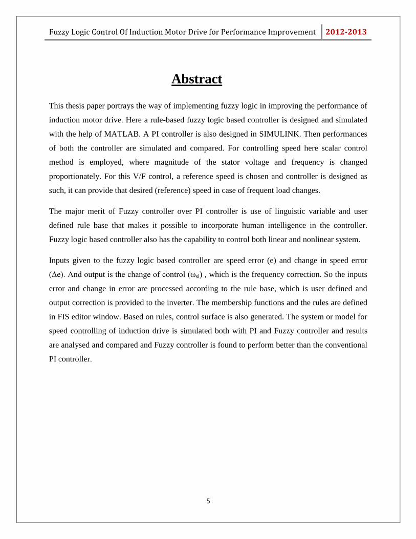
Abstract
This thesis paper portrays the way of implementing fuzzy logic in improving the performance of
induction motor drive. Here a rule-based fuzzy logic based controller is designed and simulated
with the help of MATLAB. A PI controller is also designed in SIMULINK. Then performances
of both the controller are simulated and compared. For controlling speed here scalar control
method is employed, where magnitude of the stator voltage and frequency is changed
proportionately. For this V/F control, a reference speed is chosen and controller is designed as
such, it can provide that desired (reference) speed in case of frequent load changes.
The major merit of Fuzzy controller over PI controller is use of linguistic variable and user
defined rule base that makes it possible to incorporate human intelligence in the controller.
Fuzzy logic based controller also has the capability to control both linear and nonlinear system.
Inputs given to the fuzzy logic based controller are speed error (e) and change in speed error
(Δe). And output is the change of control (ωsl) , which is the frequency correction. So the inputs
error and change in error are processed according to the rule base, which is user defined and
output correction is provided to the inverter. The membership functions and the rules are defined
in FIS editor window. Based on rules, control surface is also generated. The system or model for
speed controlling of induction drive is simulated both with PI and Fuzzy controller and results
are analysed and compared and Fuzzy controller is found to perform better than the conventional
PI controller.
Fuzzy Logic Control Of Induction Motor Drive for Performance Improvement 2012-2013
6
CONTENTS
Abstract 5
Contents 6
List of Tables 9
List of Figures 10
CHAPTER 1
INTRODUCTION
1.1 Introduction 13
1.2 Merits of fuzzy logic based controller 13
1.3 Objective of the project 14
1.4 Scope of the Project 14
1.5 Organization of the report 14
CHAPTER 2
INDUCTION MOTOR DRIVE
2.1 Introduction 16
2.2 Construction of induction motor 16
2.2.1 Stator parts 16
2.2.2 Rotor parts 17
2.2.3 Working of induction motor 19
2.3 Summary 20
Fuzzy Logic Control Of Induction Motor Drive for Performance Improvement 2012-2013
7
CHAPTER-3
SPEED CONTROL TECHNIQUES
3.1 Introduction 22
3.2 Types of speed control 22
3.3 V/F control overview 23
3.4 Constant V/F control 25
3.5 Summary 27
CHAPTER-4
PI CONTROLLER
4.1 Introduction 29
4.2 Closed loop v/f control method using PI controller 30
4.3 Summary 31
CHAPTER-5
FUZZY SET THEORY
5.1 Introduction 33
5.2 Fuzzy set operations 33
5.3 Membership function 34
5.4 Summary 36
CHAPTER-6
FUZZY LOGIC CONTROLLER
6.1 Introduction 38
6.2 Configuration of FLC 38
6.3 Summary 40
Fuzzy Logic Control Of Induction Motor Drive for Performance Improvement 2012-2013
8
CHAPTER-7
DESIGN OF FUZZY LOGIC CONTROLLER
7.1 Introduction 42
7.2 Design of fuzzy controller 43
7.3 Selecting and designing membership function for inputs 43
7.4 Selecting and designing membership function for output 45
7.5 Rule base 46
7.6 Programming with MATLAB 46
7.7 Summary 54
CHAPTER-8
MATLAB SIMULATION
8.1 Simulink model for controlling speed of an induction drive 56
8.2 Simulation and result 68
8.3 Comparison between results 60
8.4 Conclusion 61
CHAPTER-9
CONCLUSION
9.1 Comparison between FLC and conventional controller 63
9.2 Discussion 63
9.3 Future scope 64
References 65

Fuzzy Logic Control Of Induction Motor Drive for Performance Improvement 2012-2013
9
List of Tables
Table no. Title Page no.
1 Fuzzy set and MFs for input error(e) 43
2 Fuzzy set and MFs for input change in
error(Δe)
44
3 Fuzzy set and MFs for output change in
control(ωsl)
45
4 Rule base table 46
5 Comparison table between different
controllers
60
Fuzzy Logic Control Of Induction Motor Drive for Performance Improvement 2012-2013
10
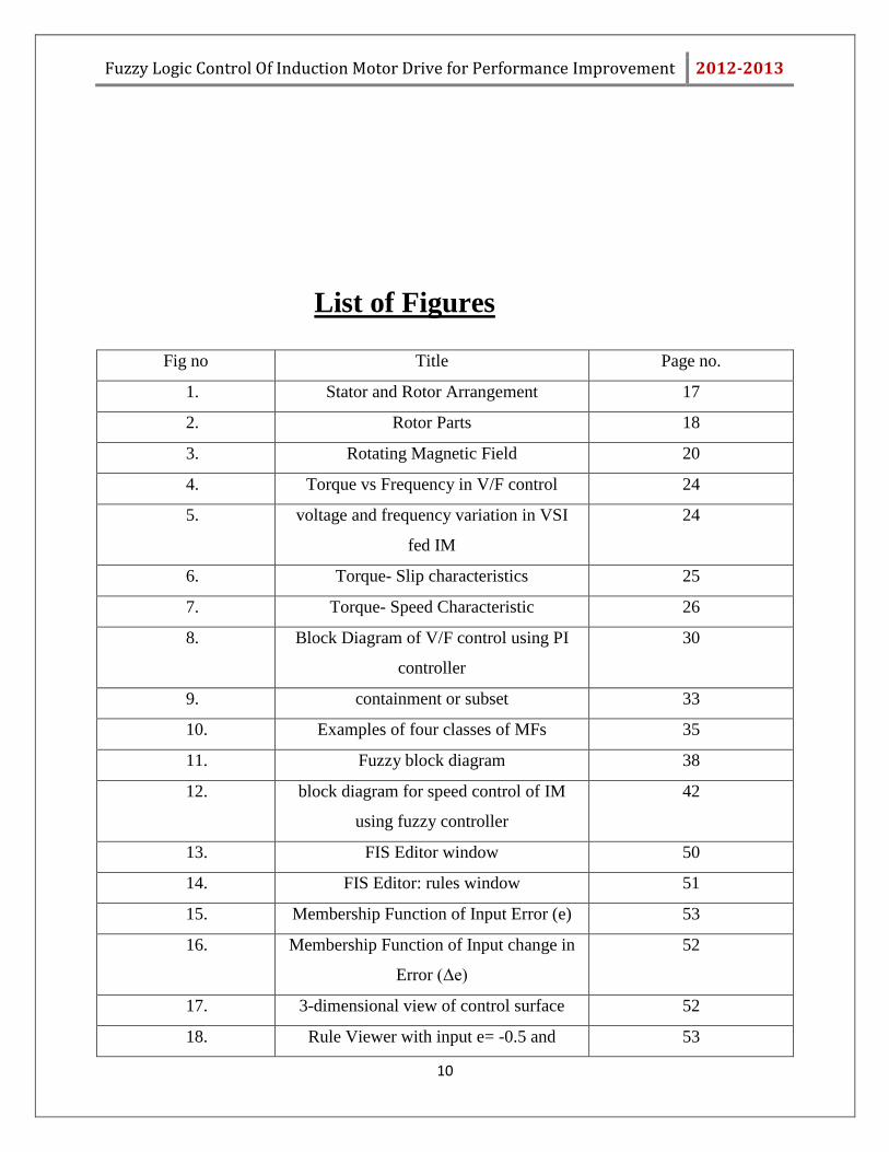
List of Figures
Fig no Title Page no.
1. Stator and Rotor Arrangement 17
2. Rotor Parts 18
3. Rotating Magnetic Field 20
4. Torque vs Frequency in V/F control 24
5. voltage and frequency variation in VSI
fed IM
24
6. Torque- Slip characteristics 25
7. Torque- Speed Characteristic 26
8. Block Diagram of V/F control using PI
controller
30
9. containment or subset 33
10. Examples of four classes of MFs 35
11. Fuzzy block diagram 38
12. block diagram for speed control of IM
using fuzzy controller
42
13. FIS Editor window 50
14. FIS Editor: rules window 51
15. Membership Function of Input Error (e) 53
16. Membership Function of Input change in
Error (Δe)
52
17. 3-dimensional view of control surface 52
18. Rule Viewer with input e= -0.5 and 53
Fuzzy Logic Control Of Induction Motor Drive for Performance Improvement 2012-2013
11
Δe=0.3
19. Rule Viewer with e = 0.2 and Δe = 0.3 53
20. Block diagram for controlling speed of the
induction motor using speed controller
56
21. Block diagram of PI Speed controller 57
22. Block diagram of Fuzzy Logic based
Speed controller
58
23. Speed vs. Time plot with reference speed
of 1000rpm using PI controller
59
24. Speed vs. Time plot with reference speed
of 1000rpm using Fuzzy controller
59

Fuzzy Logic Control Of Induction Motor Drive for Performance Improvement 2012-2013
12
Chapter 1
Introduction
Fuzzy Logic Control Of Induction Motor Drive for Performance Improvement 2012-2013
13
1.1 Introduction
In recent years the control of high-performance induction motor drives has received widespread
research interests. It has been valued more not only because it is the most used motor in
industries but also due to their varied modes of operation. Also it has good self-starting
capability, simple, rugged structure, low cost and reliability etc. Main property that makes it
more useful for industries is its low sensibility to disturbance and maintenance free operation.
Despite of many advantages of induction motor there are some disadvantages also. Like it is not
true constant speed motor, slip varies from less than 1% to more than 5%. Also it is not capable
of providing variable speed operation. But as it is so useful for industries we have to find some
solution to solve these limitations and the solution is speed controller, that can take necessary
control action to provide the required speed. Not only speed, it can control various parameters of
the induction machine such as flux, torque, voltage, stator current. Out of the several methods of
speed control of an induction such as changing no of pole, rotor resistance control, stator voltage
control, slip power recovery scheme and constant V/f control, the closed loop constant V/f speed
control method is most popular method used for controlling speed. In this method, the V/f ratio is
kept constant which in turn maintains the magnetizing flux constant that eliminates harmonic
problem and also the maximum torque also does not change. So, it‟s a kind of complete
utilization of the motor. And the controller used are conventional P-I controller, and fuzzy logic
controller.
1.2 Merits of Fuzzy Logic based Controller:
1. It can corporate human intelligence in control algorithm.
2. No perfect mathematical model of the process plant is necessary.
3. It can work effectively both for linear and non-linear system.
4. Speed of response is high and overshooting is less.
5. Linguistic variables are used in place of numerical variable.
6. Degree of precision is very high.
Fuzzy Logic Control Of Induction Motor Drive for Performance Improvement 2012-2013
14
1.3 Objective of the Project:
The main objective of the project is to design and develop a Fuzzy Logic based Controller which
can take necessary control action to provide the desired speed. The control method used here is
scalar control method where magnitude of the stator voltage and frequency is changed
proportionally to keep the main flux constant.
1.4 Scope of the Project:
Scope of the project is:
Designing and developing a speed controller using the fuzzy logic approach employing
the scalar control model.
producing a learning package of Fuzzy Logic Controller which can be used for future
reference
1.5 Organization of the Report:
This document deals with the proposed idea of using Fuzzy Controller as the speed controller to
efficiently control the speed in the scalar control method. Conventional controller is also there.
But in this document it is compared and proved the fuzzy controller works more efficiently than
other conventional controller to control the speed of the induction motor drive.
Total document is divided into 9 different chapters.
Chapter 2 briefly explains the induction motor drive
Chapter 3 explains all the speed control techniques available to control the speed of the induction
motor drive including V/F control.
Chapter 4 is the designing of a speed controller using conventional PI controller.
Chapter 5 overviews the fuzzy set, membership functions and operations on fuzzy sets.
Chapter 6 is the brief discussion on fuzzy controller and chapter 7 is the complete design of the
fuzzy based controller.
Chapter 8 shows all MATLAB simulations and results and finally chapter 9 is the conclusion.
Fuzzy Logic Control Of Induction Motor Drive for Performance Improvement 2012-2013
15
Chapter 2
Induction Motor Drive

Fuzzy Logic Control Of Induction Motor Drive for Performance Improvement 2012-2013
16
2.1 Introduction
The most commonly encountered electric motors in industry are induction motors. In recent
years the control of high-performance induction motor drives has received widespread research
interests. It has been valued more not only because it is the most used motor in industries but
also due to their varied modes of operation. It has good self-starting capability, simple, rugged
structure, low cost and reliability etc. Induction motors have been used in past mainly in
applications requiring a constant speed. It has attracted the attention because such machine are
made and used in largest numbers and also due to their varied mode of operation both under
steady state and dynamic states. Induction motor finds its place amongst more than 85% of
industrial motor drives and as well as single phase form in various domestic usages.
2.2 Construction of Induction Motor
2.2.1 Stator Parts
Frame: The frame of an induction motor may be cast or fabricated, depending upon the size of
the motor. It is cheaper to use cast iron where losses and efficiency is of a lesser consideration
than economy and where new designs and modifications are not to be done on the machine.
However, for medium-sized and (in particular) large induction motors, fabricated frame structure
is exclusively used. The outer surface is provided with cooling fins so as to increase the heat
dissipating area without increasing the overall diameter. The chief advantage of fabricated
construction is in its application to new design and modifications. And these modifications can
be made without reference to previously existing patterns.
Frame gives full support and protection to the other parts and an eye-bolt on its top is useful for
transit purposes.
Stator Core: The stator core provides the space for housing for the three-phase stator
windings and also forms the path for the rotating magnetic field. They are built up of thin sheets
of thickness (called stampings or laminations) of 0.35 mm to 0.65 mm with of a special core of
steel, insulated one from the other by paper insulation. The gap facing inner circumference of the
Fuzzy Logic Control Of Induction Motor Drive for Performance Improvement 2012-2013
17
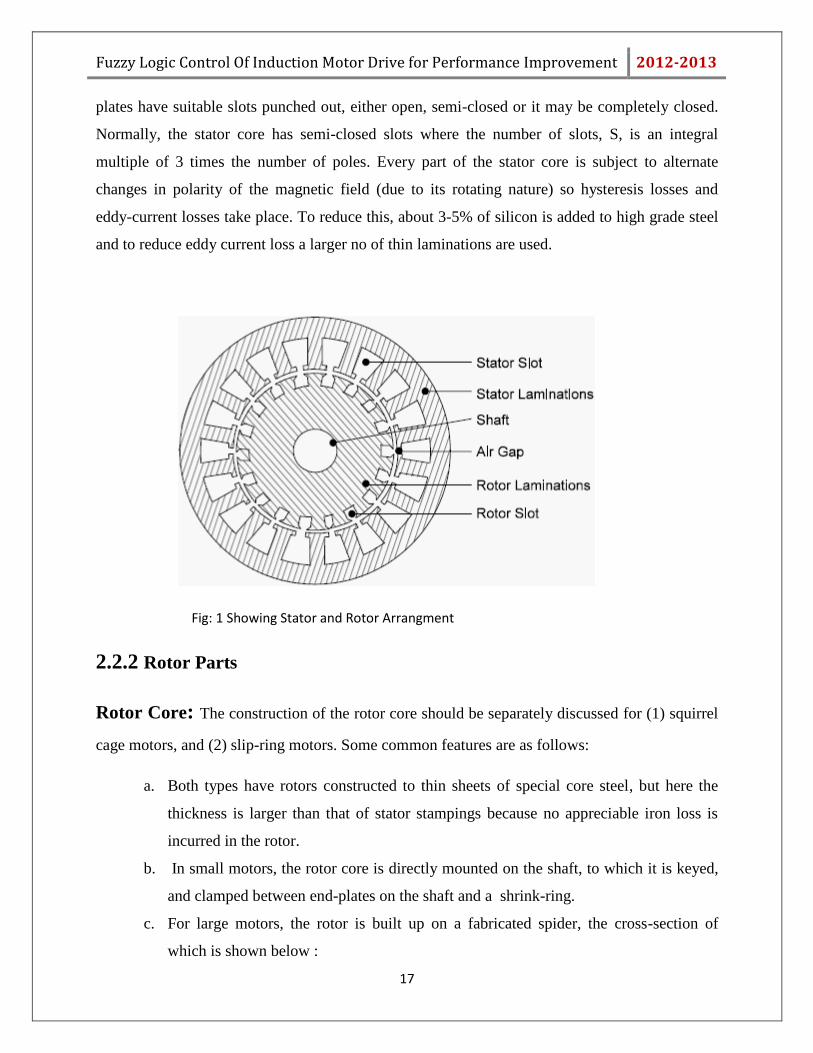
plates have suitable slots punched out, either open, semi-closed or it may be completely closed.
Normally, the stator core has semi-closed slots where the number of slots, S, is an integral
multiple of 3 times the number of poles. Every part of the stator core is subject to alternate
changes in polarity of the magnetic field (due to its rotating nature) so hysteresis losses and
eddy-current losses take place. To reduce this, about 3-5% of silicon is added to high grade steel
and to reduce eddy current loss a larger no of thin laminations are used.
Fig: 1 Showing Stator and Rotor Arrangment
2.2.2 Rotor Parts
Rotor Core: The construction of the rotor core should be separately discussed for (1) squirrel
cage motors, and (2) slip-ring motors. Some common features are as follows:
a. Both types have rotors constructed to thin sheets of special core steel, but here the
thickness is larger than that of stator stampings because no appreciable iron loss is
incurred in the rotor.
b. In small motors, the rotor core is directly mounted on the shaft, to which it is keyed,
and clamped between end-plates on the shaft and a shrink-ring.
c. For large motors, the rotor is built up on a fabricated spider, the cross-section of
which is shown below :
Fuzzy Logic Control Of Induction Motor Drive for Performance Improvement 2012-2013
18
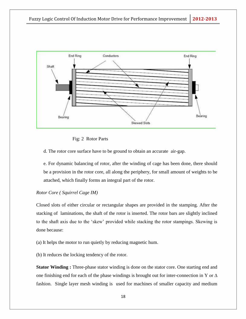
Fig: 2 Rotor Parts
d. The rotor core surface have to be ground to obtain an accurate air-gap.
e. For dynamic balancing of rotor, after the winding of cage has been done, there should
be a provision in the rotor core, all along the periphery, for small amount of weights to be
attached, which finally forms an integral part of the rotor.
Rotor Core ( Squirrel Cage IM)
Closed slots of either circular or rectangular shapes are provided in the stamping. After the
stacking of laminations, the shaft of the rotor is inserted. The rotor bars are slightly inclined
to the shaft axis due to the „skew‟ provided while stacking the rotor stampings. Skewing is
done because:
(a) It helps the motor to run quietly by reducing magnetic hum.
(b) It reduces the locking tendency of the rotor.
Stator Winding : Three-phase stator winding is done on the stator core. One starting end and
one finishing end for each of the phase windings is brought out for inter-connection in Y or ∆
fashion. Single layer mesh winding is used for machines of smaller capacity and medium
Fuzzy Logic Control Of Induction Motor Drive for Performance Improvement 2012-2013
19
sized machines have double-layer lap windings. Large capacity motors employ single layer
concentric winding.
Rotor Cage or Rotor Winding
In slip ring motors, there is a rotor winding on the rotor cage and hence are called the
wound rotor motors. The rotor is wound for the same number of poles as that of stator. The
winding is normally connected in star and the resultant three terminals are connected to three
slip-rings provided on one end of the shaft.
2.2.3 Working Of Induction Motor:
Principles of Rotating Magnetic Field.
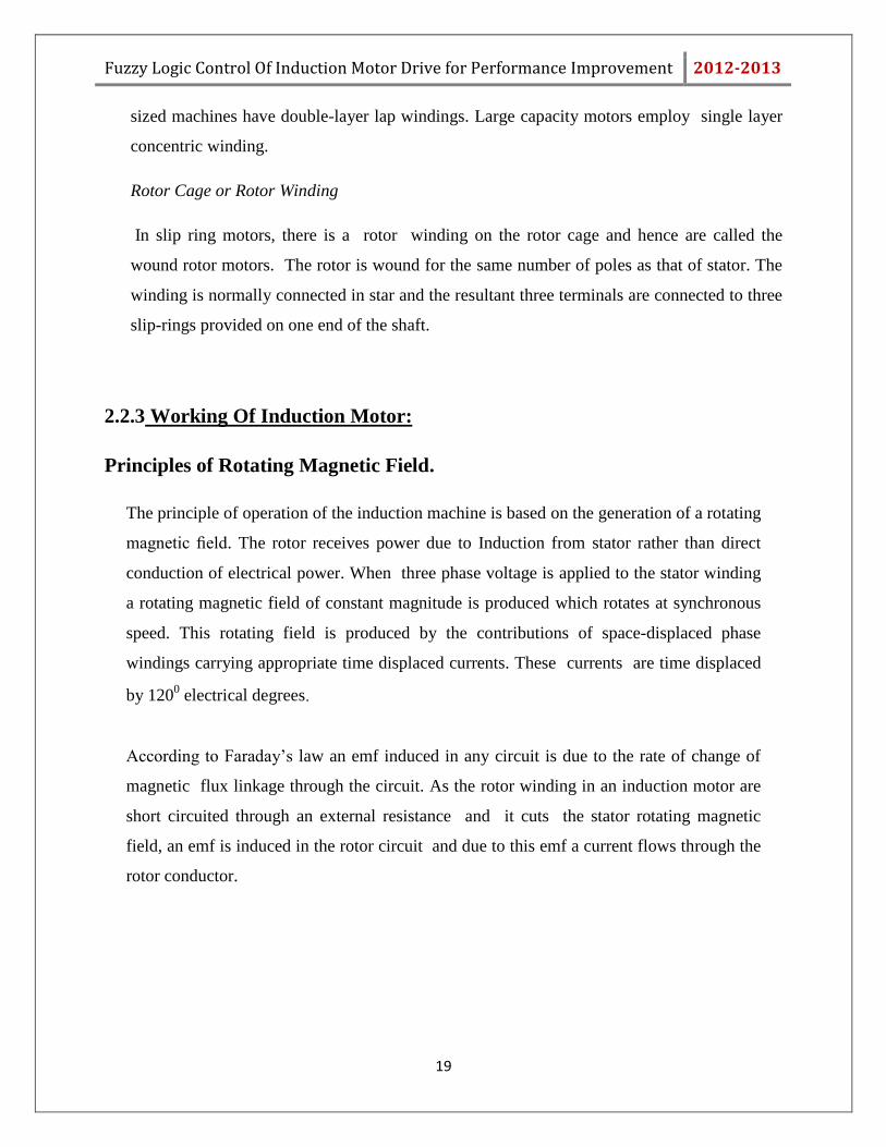
The principle of operation of the induction machine is based on the generation of a rotating
magnetic field. The rotor receives power due to Induction from stator rather than direct
conduction of electrical power. When three phase voltage is applied to the stator winding
a rotating magnetic field of constant magnitude is produced which rotates at synchronous
speed. This rotating field is produced by the contributions of space-displaced phase
windings carrying appropriate time displaced currents. These currents are time displaced
by 1200 electrical degrees.
According to Faraday‟s law an emf induced in any circuit is due to the rate of change of
magnetic flux linkage through the circuit. As the rotor winding in an induction motor are
short circuited through an external resistance and it cuts the stator rotating magnetic
field, an emf is induced in the rotor circuit and due to this emf a current flows through the
rotor conductor.
Fuzzy Logic Control Of Induction Motor Drive for Performance Improvement 2012-2013
20
Fig: 3 Rotating Magnetic Field
Here the relative velocity between the rotating flux and static rotor conductor is the cause of
electric current generation, hence per Lenz‟s law rotor will rotate in the direction to reduce
the cause i.e the relative velocity.
From working of Induction Motor it may be observed that the rotor should not reach the
synchronous speed .If the speed equals there would be no relative velocity. So there will be
no cutting of flux so no emf can be generated, means no current will be flowing. And no
torque will be generated. The difference between the stator speed and rotor speed is called
slip.
Summary: This chapter describes about principle of induction motor, it includes its
constructional details, working and operation of Induction motors. It is a singly-fed motor
unlike the synchronous motor which calls for ac supply on the stator side and dc excitation on
the rotor. Torque developed Induction motor originates from interaction of rotor current and
flux. It is also known as asynchronous machine. The air-gap excitation current is much
larger in an induction motor than in a transformer for the same power rating, it inherently has
a power factor less than unity as the energy conversation is taking place via air gap.
Fuzzy Logic Control Of Induction Motor Drive for Performance Improvement 2012-2013
21
Chapter 3
Speed Control Techniques
Fuzzy Logic Control Of Induction Motor Drive for Performance Improvement 2012-2013
22
3.1Introduction:
The speed control of induction motor is more complicated than that of dc motor, especially
when , comparable accuracy is desired. The main reason for this can be attributed to the
complexity of the mathematical model of the induction machine, as well as the non-linear
power converters supplying this motor. It is very important to control the speed of induction
motor for the application in industries and in engineering.
There are many types of speed control. Speed control techniques of induction motors can be
broadly classified into two types scalar control and vector control. Scalar method only the
magnitude of voltage or frequency of the induction motor.
3.2 Types Of speed control:
Mathematically, the relation between the speed of an induction motor and the synchronous
speed(speed of rotating flux) can be stated as:
Nr = (1-s) Ns
Ns = 120f/p
Where, Nr is the rotor speed
Ns Is the synchronous speed.
s is the slip
f is the supply frequency
as speed is a function of frequency and no. of poles , speed can be varied by varying these
parameters.
Fuzzy Logic Control Of Induction Motor Drive for Performance Improvement 2012-2013
23
Different ways of controlling speed of induction motor are:
1. Changing no. of poles
2. Stator voltage control
3. Rotor resistance control
4. Slip power recovery scheme, and
5. Constant V/f control
AC motors have traditionally operated at fixed frequency and speed .when load changes speed
also gets changed. With increasing load, speed gets decreased and with decrease of load, speed
rises. but as that drop is small percentage of full load speed, so that speed is considered to be
constant with changing load.
Out of all the above methods induction motor speed variation can be easily achieved for a short
range by either stator voltage control or rotor resistance control. But it may leads to lower
efficiency.
Also in stator voltage control method, as voltage is varied to vary the speed and torque is
proportional to square of applied stator voltage, so in this method to vary speed, torque also gets
affected. Also in other methods like rotor resistance control, part of power get lost in the
resistor. So, efficiency gets reduced. So, this is also not a suitable control.
The most efficient scheme for speed control of induction motor is by varying supply frequency.
3.3 V/f Control Overview:
Induction motor speed variation can be easily achieved for a short range by either stator voltage
control or rotor resistance control. But at low speed it result in low efficiency. The most efficient
scheme for speed control of induction motor is by varying supply frequency. This results in
scheme with wide speed range but also improves the starting performance.
The v/f ratio is kept constant, when the machine is operating at speed below base speed,
so that flux remains constant. Maximum torque remains constant in this case. At frequency less
than rated frequency, the torque capability decrease and this drop in torque has to be
compensated by increasing the applied voltage.
Fuzzy Logic Control Of Induction Motor Drive for Performance Improvement 2012-2013
24
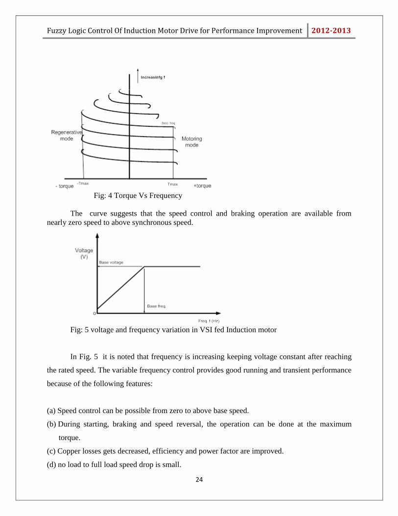
Fig: 4 Torque Vs Frequency
The curve suggests that the speed control and braking operation are available from
nearly zero speed to above synchronous speed.
Fig: 5 voltage and frequency variation in VSI fed Induction motor
In Fig. 5 it is noted that frequency is increasing keeping voltage constant after reaching
the rated speed. The variable frequency control provides good running and transient performance
because of the following features:
(a) Speed control can be possible from zero to above base speed.
(b) During starting, braking and speed reversal, the operation can be done at the maximum
torque.
(c) Copper losses gets decreased, efficiency and power factor are improved.
(d) no load to full load speed drop is small.
Fuzzy Logic Control Of Induction Motor Drive for Performance Improvement 2012-2013
25
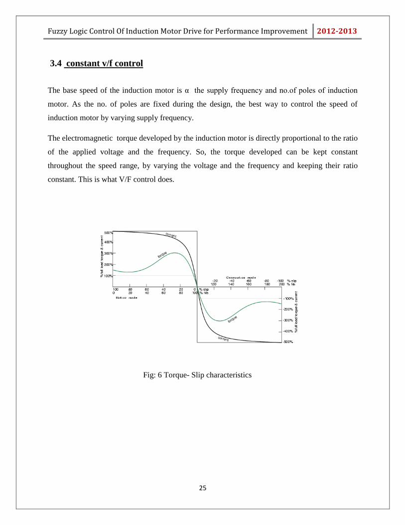
3.4 constant v/f control
The base speed of the induction motor is α the supply frequency and no.of poles of induction
motor. As the no. of poles are fixed during the design, the best way to control the speed of
induction motor by varying supply frequency.
The electromagnetic torque developed by the induction motor is directly proportional to the ratio
of the applied voltage and the frequency. So, the torque developed can be kept constant
throughout the speed range, by varying the voltage and the frequency and keeping their ratio
constant. This is what V/F control does.
Fig: 6 Torque- Slip characteristics
Fuzzy Logic Control Of Induction Motor Drive for Performance Improvement 2012-2013
26
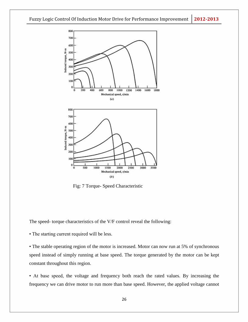
Fig: 7 Torque- Speed Characteristic
The speed- torque characteristics of the V/F control reveal the following:
• The starting current required will be less.
• The stable operating region of the motor is increased. Motor can now run at 5% of synchronous
speed instead of simply running at base speed. The torque generated by the motor can be kept
constant throughout this region.
• At base speed, the voltage and frequency both reach the rated values. By increasing the
frequency we can drive motor to run more than base speed. However, the applied voltage cannot
Fuzzy Logic Control Of Induction Motor Drive for Performance Improvement 2012-2013
27
be increased beyond the rated voltage. So after reaching the rated voltage, only frequency can be
increased which results in torque reduction.
• By controlling the supply frequency to the motor, the acceleration and deceleration of the
motor can be controlled with respect to time.
3.5 Summary:-
In this chapter we studied about different types of speed control techniques in Induction Motor.
The most favourable way of speed control is V/F control as Speed can be changed above and
below the base speed by this method and the starting current requirement is also very low. Due to
many advantages V/F control is adopted for the speed control of Induction Motor.
Fuzzy Logic Control Of Induction Motor Drive for Performance Improvement 2012-2013
28
Chapter 4
P-I CONTROLLER
Fuzzy Logic Control Of Induction Motor Drive for Performance Improvement 2012-2013
29
4.1 Introduction
Induction machines are most frequently used in industries due to their robustness, low cost and
reliability and high efficiency. Squirrel cage rotor, is the most widely used source of mechanical
power fed from AC power system due to its low sensitivity to disturbance.
In spite of many advantages Induction motor has two inherent limitations.
It is not a true constant speed machine (slip varies from 1% to 5% during operation).
It is not capable of providing variable speed operation.
During starting , Induction motor draws large current which produces voltage dips oscillatory
torques and also able to generate harmonics in the power system.
When accuracy in speed response is a concern, closed-loop speed control is implemented
with the constant V/F control. A PI controller is employed to regulate the slip speed of the
motor to keep the motor speed at its set value.
4.2 Closed loop V/F speed control method by using PI controller:
Speed control could have been done with open-loop also. Open-loop control is the simplest type
of control without any feedback loop, and without much complexity. But there lies many
advantages of closed loop control over open loop control, for which closed loop control is
preferred over open loop control.
(1) The controlled variable (speed) accurately follows the desired value(specified speed).
(2) Effect of external disturbances on controlled variable(speed) is very less
(3) Also, use of feedback in the control greatly improves the speed of its response
compared to that of open-loop case.
Fuzzy Logic Control Of Induction Motor Drive for Performance Improvement 2012-2013
30
K1+K2/S INVERTER
V/f
IM
Speed
Encoder
ωr
ωref
ωr-
++
+
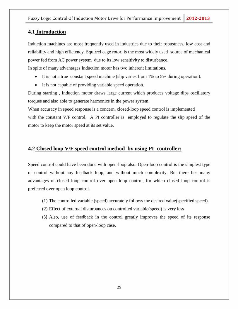
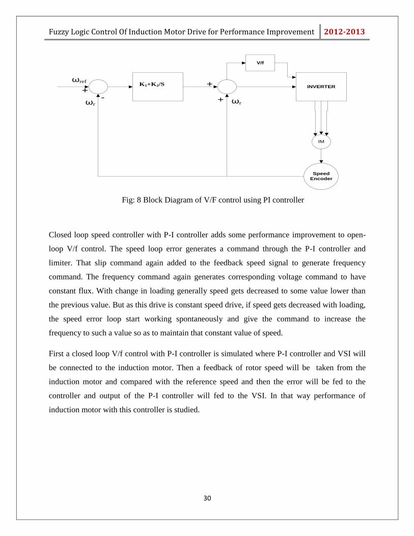
Fig: 8 Block Diagram of V/F control using PI controller
Closed loop speed controller with P-I controller adds some performance improvement to open-
loop V/f control. The speed loop error generates a command through the P-I controller and
limiter. That slip command again added to the feedback speed signal to generate frequency
command. The frequency command again generates corresponding voltage command to have
constant flux. With change in loading generally speed gets decreased to some value lower than
the previous value. But as this drive is constant speed drive, if speed gets decreased with loading,
the speed error loop start working spontaneously and give the command to increase the
frequency to such a value so as to maintain that constant value of speed.
First a closed loop V/f control with P-I controller is simulated where P-I controller and VSI will
be connected to the induction motor. Then a feedback of rotor speed will be taken from the
induction motor and compared with the reference speed and then the error will be fed to the
controller and output of the P-I controller will fed to the VSI. In that way performance of
induction motor with this controller is studied.
Fuzzy Logic Control Of Induction Motor Drive for Performance Improvement 2012-2013
31
4.3 Summary:
A systematic approach of achieving robust speed control of an induction motor drive by means
of P-I has been investigated. Whenever the induction machine was loaded the speed of the
machine fell, but constant speed drive demands a constant speed throughout its application
irrespective of loading. So to provide that constant speed P-I controller in a closed V/f loop is
used where it generates the required speed command to provide the desired constant speed. From
the speed vs time graph it can be seen and concluded that speed remains constant irrespective of
motor loading, and from stator current vs time it can be seen that current increases with
increasing load.

Fuzzy Logic Control Of Induction Motor Drive for Performance Improvement 2012-2013
32
Chapter 5
FUZZY SET THEORY
Fuzzy Logic Control Of Induction Motor Drive for Performance Improvement 2012-2013
33
5.1 Introduction:
Fuzzy logic is a superset of Boolean logic which has been extended to handle the concept of
partial truth- truth values between "completely true" and "completely false". It is the logic basic
modes of reasoning which are approximate rather than exact. Fuzzy logic replicates human
knowledge in to control logic. The essential characteristics of fuzzy logic as founded by Zader
Lotfi are as follows.
Any logical system can be fuzzified.
In fuzzy logic, knowledge is interpreted as a collection of elastic or, equivalently , fuzzy
constraint on a collection of variables
No need of any exact mathematical model.
5.2Fuzzy Set Operations
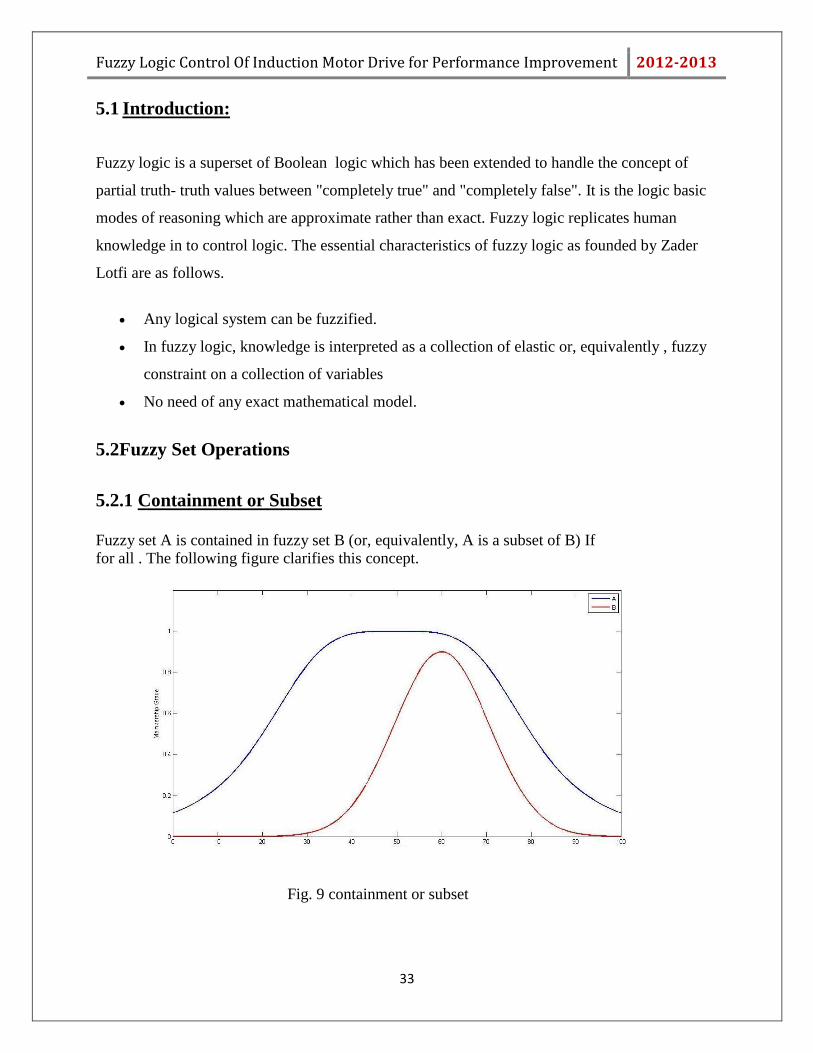
5.2.1 Containment or Subset
Fuzzy set A is contained in fuzzy set B (or, equivalently, A is a subset of B) If for all . The following figure clarifies this concept.
Fig. 9 containment or subset
Fuzzy Logic Control Of Induction Motor Drive for Performance Improvement 2012-2013
34
5.2.2 Union The membership function of the Union of two fuzzy sets A and B with membership
functions µA and µB respectively is defined as the maximum of the two individual membership
functions. This is called the maximum criterion.[1]
5.2.3 Intersection (Conjunction)
Intersection of two fuzzy sets can be written as C=A or B. where C is the resultant set
Intersection of A and B is the largest fuzzy set contained both in A and B. An intersection of two
fuzzy sets A and B
5.2.4 Complement (Negation) The complement of fuzzy set A, symboled by Ā ( A, NOT A).
5.3 Membership Function:-
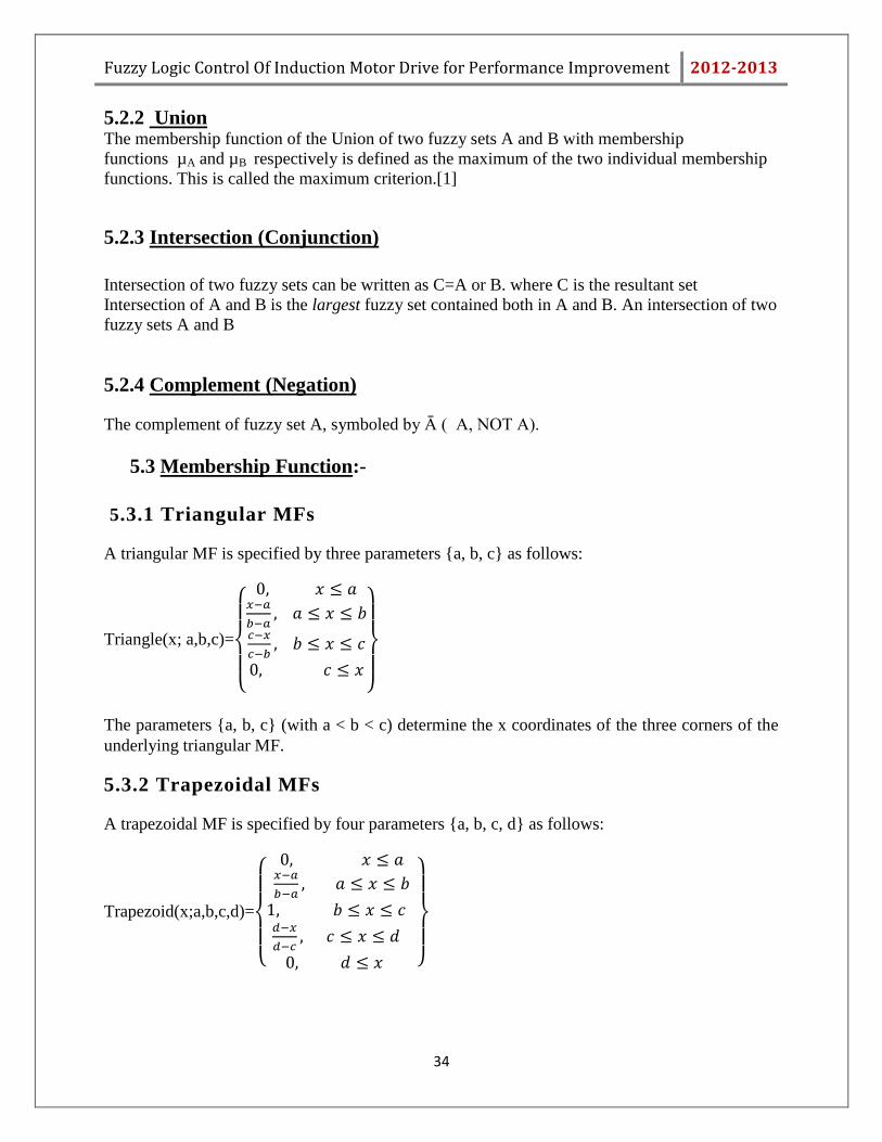
5.3.1 Triangular MFs
A triangular MF is specified by three parameters {a, b, c} as follows:
Triangle(x; a,b,c)=
{
}
The parameters {a, b, c} (with a < b < c) determine the x coordinates of the three corners of the
underlying triangular MF.
5.3.2 Trapezoidal MFs
A trapezoidal MF is specified by four parameters {a, b, c, d} as follows:
Trapezoid(x;a,b,c,d)=
{
}
Fuzzy Logic Control Of Induction Motor Drive for Performance Improvement 2012-2013
35
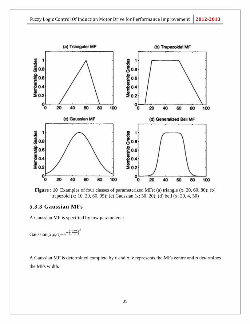
Figure : 10 Examples of four classes of parameterized MFs: (a) triangle (x; 20, 60, 80); (b)
trapezoid (x; 10, 20, 60, 95); (c) Gaussian (x; 50, 20); (d) bell (x; 20, 4, 50)
5.3.3 Gaussian MFs
A Gaussian MF is specified by tow parameters :
Gaussian(x;c,σ)=
(
)
A Gaussian MF is determined complete by c and σ; c represents the MFs centre and σ determines
the MFs width.

Fuzzy Logic Control Of Induction Motor Drive for Performance Improvement 2012-2013
36
5.3.4 Generalised bell MFs
A generalized bell MF (or Bell-shaped Function) is specified by three parameters {a, b, c}:
Bell(x;a,b,c)=
Where, the parameter b is usually positive.
The Gaussian MFs and bell MFs achieve smoothness, they can not specify asymmetric MFs,
which is needed in some applications. Then the sigmoid MF is either open left or right.
5.3.5 Sigmoid MFs
A sigmoid MF is defined by
Sig(x;a,c)=
[ ]
5.4 Summary:
This chapter briefs the fuzzy set, some of the operation performing on the fuzzy set, membership
function types and their representation. It also explains the difference between classical set and
fuzzy set, how fuzzy set deals with linguistic variable.
Fuzzy Logic Control Of Induction Motor Drive for Performance Improvement 2012-2013
37
Chapter 6
Fuzzy Logic Controller
Fuzzy Logic Control Of Induction Motor Drive for Performance Improvement 2012-2013
38
6.1 Introduction
As discussed previously Fuzzy logic is a technique to inculcate human-like thinking into a
control system. So the main purpose of designing fuzzy controller is to embody the human
intelligence or human like thinking in the controller to control the process parameters.
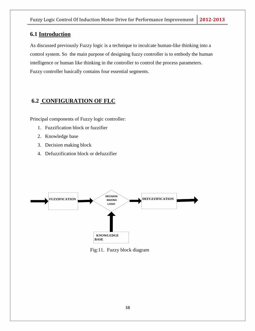
Fuzzy controller basically contains four essential segments.
6.2 CONFIGURATION OF FLC
Principal components of Fuzzy logic controller:
1. Fuzzification block or fuzzifier
2. Knowledge base
3. Decision making block
4. Defuzzification block or defuzzifier
FUZZIFICATION
KNOWLEDGE
BASE
DECISION
MAKING
LOGIC
DEFUZZIFICATION
Fig:11. Fuzzy block diagram

Fuzzy Logic Control Of Induction Motor Drive for Performance Improvement 2012-2013
39
6.2.1 Fuzzifier:
As discussed previously fuzzy logic based on linguistic variable but since input given to the FLC
block is in numeric form so first thing to be done is to convert the numerical data/variable into
linguistic variable. And this task is performed by the fuzzifier. So fuzzifier converts the
numerical variable given to the FLC into linguistic variable. This fuzzification task includes
choosing proper MF for the variables so that the crisp inputs can be converted into fuzzy sets.
6.2.2 Knowledge base:
Knowledge base is consist of rule base and data base. The main aim of data base is to provide
necessary definitions needed to define the linguistic control rules and the aim of rule base is to
characterize the control goals and policies by using a set of linguistic or If-Then rules. In the If-
Then statement, the if part is called antecedent and the then part is called consequence.
6.2.3 Decision Making Block:
It is the most important component of a fuzzy controller because it is the block the decides the
output depending upon the input. Based on fuzzy concepts , data and rule bases, it provide
reasonable output.
6.2.4 Defuzzifier:
İt performs the task just opposite to that of fuzzifier. So the task of defuzzifier is to convert the
linguistic variable into crisp one.
There are different types of defuzzification techniques present for defuzzication.
1. Centroid of Area (COA)
2. Bisector of Area (BOA)
3. Mean of Maximum (MOM)
4. Smallest of Minimum (SOM)
5. Largest of Maximum (LOM)
In our controller design centroid of area technique is used for defuzzification.
Fuzzy Logic Control Of Induction Motor Drive for Performance Improvement 2012-2013
40
6.3 Summary:
So steps to design a Fuzzy Logic Controller at a glance is as follows:
1. Selecting the input to the FLC
2. Selecting proper MFs both for input and output variables
3. Fuzzification of the input variable
4. Preparing a Fuzzy rule base for the controller
5. Selecting proper defuzzification technique
6. Defuzzification of output that is to be given to the system for desired operation.
Fuzzy Logic Control Of Induction Motor Drive for Performance Improvement 2012-2013
41
Chapter 7
Design of fuzzy logic
controller
Fuzzy Logic Control Of Induction Motor Drive for Performance Improvement 2012-2013
42
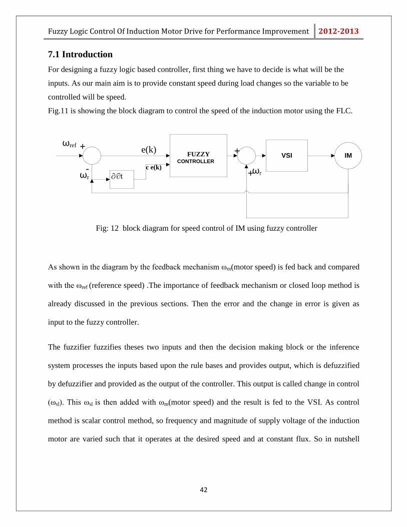
7.1 Introduction
For designing a fuzzy logic based controller, first thing we have to decide is what will be the
inputs. As our main aim is to provide constant speed during load changes so the variable to be
controlled will be speed.
Fig.11 is showing the block diagram to control the speed of the induction motor using the FLC.
FUZZY CONTROLLER
VSI IM
∂∕∂t
e(k)
c e(k)
ωref
-
+
+
+
ωrωr
Fig: 12 block diagram for speed control of IM using fuzzy controller
As shown in the diagram by the feedback mechanism ωm(motor speed) is fed back and compared
with the ωref (reference speed) .The importance of feedback mechanism or closed loop method is
already discussed in the previous sections. Then the error and the change in error is given as
input to the fuzzy controller.
The fuzzifier fuzzifies theses two inputs and then the decision making block or the inference
system processes the inputs based upon the rule bases and provides output, which is defuzzified
by defuzzifier and provided as the output of the controller. This output is called change in control
(ωsl). This ωsl is then added with ωm(motor speed) and the result is fed to the VSI. As control
method is scalar control method, so frequency and magnitude of supply voltage of the induction
motor are varied such that it operates at the desired speed and at constant flux. So in nutshell

Fuzzy Logic Control Of Induction Motor Drive for Performance Improvement 2012-2013
43
FLC has two input and one output. Inputs are error, e(k) and change of error, Δe(k) and output is
change in control (ωsl). Where error (e) = ωref – ωm
7.2 Design of fuzzy logic controller:
For designing the controller, first step is to choose the reference speed. Second step is to select
the inputs. Then membership functions for both input and output variable has to be chosen and
then a rule base has to be prepared.
Reference Speed for the controller : 1000rpm
Inputs for the controller:
A. Speed error (e)
B. Change or derivative of speed error(Δe)
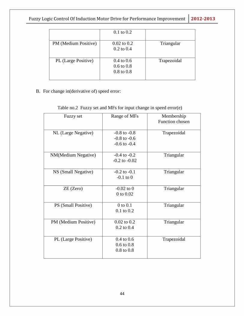
7.3 Selecting and Designing Membership Functions :
A. For speed error(e)
Table no.1 Fuzzy set and MFs for input speed error(e)
Fuzzy set Range of MFs Membership
Function chosen
NL (Large Negative) -0.8 to -0.8
-0.8 to -0.6
-0.6 to -0.4
Trapezoidal
NM(Medium Negative) -0.4 to -0.2
-0.2 to -0.02
Triangular
NS (Small Negative) -0.2 to -0.1
-0.1 to 0
Triangular
ZE (Zero) -0.02 to 0
0 to 0.02
Triangular
PS (Small Positive) 0 to 0.1 Triangular
Fuzzy Logic Control Of Induction Motor Drive for Performance Improvement 2012-2013
44
0.1 to 0.2
PM (Medium Positive) 0.02 to 0.2
0.2 to 0.4
Triangular
PL (Large Positive) 0.4 to 0.6
0.6 to 0.8
0.8 to 0.8
Trapezoidal
B. For change in(derivative of) speed error:
Table no.2 Fuzzy set and MFs for input change in speed error(e)
Fuzzy set Range of MFs Membership
Function chosen
NL (Large Negative) -0.8 to -0.8
-0.8 to -0.6
-0.6 to -0.4
Trapezoidal
NM(Medium Negative) -0.4 to -0.2
-0.2 to -0.02
Triangular
NS (Small Negative) -0.2 to -0.1
-0.1 to 0
Triangular
ZE (Zero) -0.02 to 0
0 to 0.02
Triangular
PS (Small Positive) 0 to 0.1
0.1 to 0.2
Triangular
PM (Medium Positive) 0.02 to 0.2
0.2 to 0.4
Triangular
PL (Large Positive) 0.4 to 0.6
0.6 to 0.8
0.8 to 0.8
Trapezoidal
Fuzzy Logic Control Of Induction Motor Drive for Performance Improvement 2012-2013
45
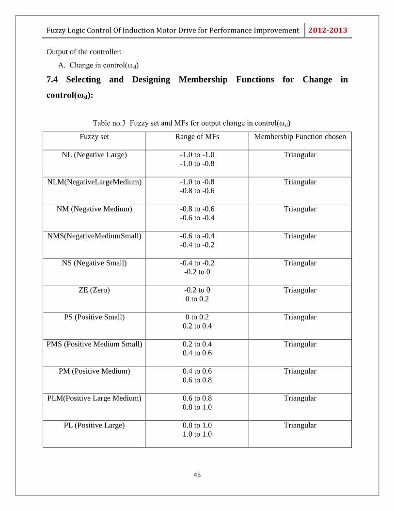
Output of the controller:
A. Change in control(ωsl)
7.4 Selecting and Designing Membership Functions for Change in
control(ωsl):
Table no.3 Fuzzy set and MFs for output change in control(ωsl)
Fuzzy set Range of MFs Membership Function chosen
NL (Negative Large) -1.0 to -1.0
-1.0 to -0.8
Triangular
NLM(NegativeLargeMedium) -1.0 to -0.8
-0.8 to -0.6
Triangular
NM (Negative Medium) -0.8 to -0.6
-0.6 to -0.4
Triangular
NMS(NegativeMediumSmall) -0.6 to -0.4
-0.4 to -0.2
Triangular
NS (Negative Small) -0.4 to -0.2
-0.2 to 0
Triangular
ZE (Zero) -0.2 to 0
0 to 0.2
Triangular
PS (Positive Small) 0 to 0.2
0.2 to 0.4
Triangular
PMS (Positive Medium Small) 0.2 to 0.4
0.4 to 0.6
Triangular
PM (Positive Medium) 0.4 to 0.6
0.6 to 0.8
Triangular
PLM(Positive Large Medium) 0.6 to 0.8
0.8 to 1.0
Triangular
PL (Positive Large) 0.8 to 1.0
1.0 to 1.0
Triangular

Fuzzy Logic Control Of Induction Motor Drive for Performance Improvement 2012-2013
46
7.5 Rule base:
As 7 speed error variables and 7 change in speed error variables are taken, so there will be total
49 rules, which will govern the decision making mechanism.
Table no.4 rule base table
Δe e NL NM NS ZE PS PM PL
NL NL NL NLM NM NMS NS ZE
NM NL NLM NM NMS NS ZE PS
NS NLM NM NMS NS ZE PS PMS
ZE NM NMS NS ZE PS PMS PM
PS NMS NS ZE PS PMS PM PLM
PM NS ZE PS PMS PM PLM PL
PL ZE PS PMS PM PLM PL PL
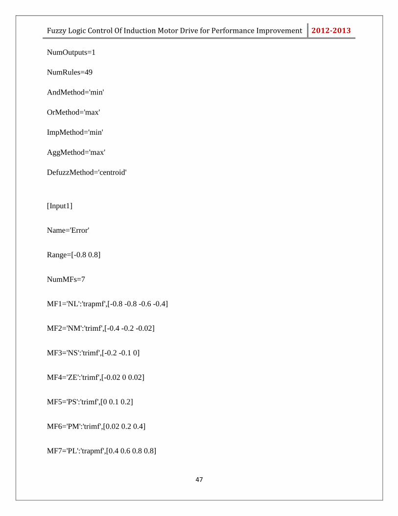
7.6 Programing with MATLAB:
To simulate the fuzzy controller in MATLAB, first the rules have to be coded.
Coded rules:
[System]
Name='rules'
Type='mamdani'
Version=2.0
NumInputs=2
Fuzzy Logic Control Of Induction Motor Drive for Performance Improvement 2012-2013
47
NumOutputs=1
NumRules=49
AndMethod='min'
OrMethod='max'
ImpMethod='min'
AggMethod='max'
DefuzzMethod='centroid'
[Input1]
Name='Error'
Range=[-0.8 0.8]
NumMFs=7
MF1='NL':'trapmf',[-0.8 -0.8 -0.6 -0.4]
MF2='NM':'trimf',[-0.4 -0.2 -0.02]
MF3='NS':'trimf',[-0.2 -0.1 0]
MF4='ZE':'trimf',[-0.02 0 0.02]
MF5='PS':'trimf',[0 0.1 0.2]
MF6='PM':'trimf',[0.02 0.2 0.4]
MF7='PL':'trapmf',[0.4 0.6 0.8 0.8]
Fuzzy Logic Control Of Induction Motor Drive for Performance Improvement 2012-2013
48
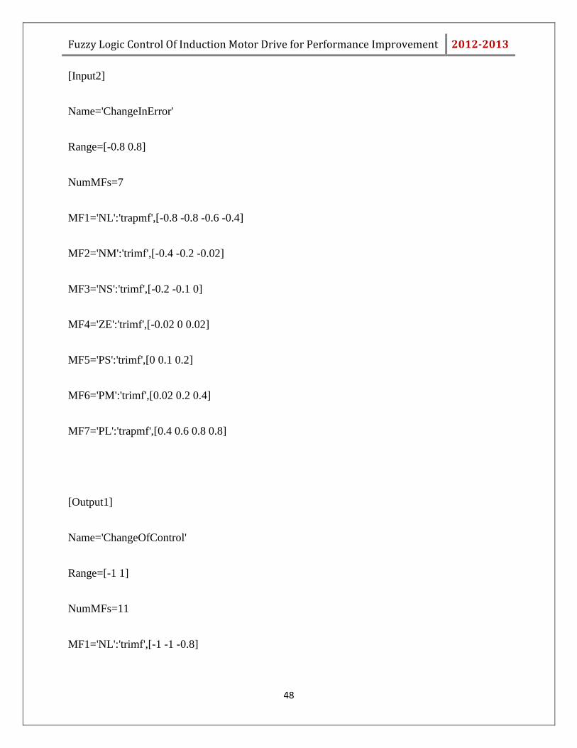
[Input2]
Name='ChangeInError'
Range=[-0.8 0.8]
NumMFs=7
MF1='NL':'trapmf',[-0.8 -0.8 -0.6 -0.4]
MF2='NM':'trimf',[-0.4 -0.2 -0.02]
MF3='NS':'trimf',[-0.2 -0.1 0]
MF4='ZE':'trimf',[-0.02 0 0.02]
MF5='PS':'trimf',[0 0.1 0.2]
MF6='PM':'trimf',[0.02 0.2 0.4]
MF7='PL':'trapmf',[0.4 0.6 0.8 0.8]
[Output1]
Name='ChangeOfControl'
Range=[-1 1]
NumMFs=11
MF1='NL':'trimf',[-1 -1 -0.8]

Fuzzy Logic Control Of Induction Motor Drive for Performance Improvement 2012-2013
49
MF2='NLM':'trimf',[-0.7 -0.5 -0.3]
MF3='NM':'trimf',[-0.6 -0.4 -0.2]
MF4='NMS':'trimf',[-0.3 -0.2 -0.1]
MF5='NS':'trimf',[-0.4 -0.2 0]
MF6='ZE':'trimf',[-0.2 0 0.2]
MF7='PS':'trimf',[0 0.2 0.4]
MF8='PSM':'trimf',[0.1 0.2 0.3]
MF9='PM':'trimf',[0.2 0.4 0.6]
MF10='PML':'trimf',[0.3 0.5 0.7]
MF11='PL':'trimf',[0.8 1 1]
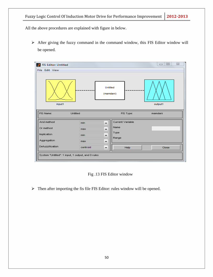
Procedure to simulate the fuzzy controller in MATLAB:
1. First rules have to coded and written in m-file and saved with .fis extension.
2. Then the FIS editor will be opened by typing fuzzy in the command window.
3. Then the required fis file has to be imported by browsing.
4. After the loading of fis file the controller is ready to be operated.
Fuzzy Logic Control Of Induction Motor Drive for Performance Improvement 2012-2013
50
All the above procedures are explained with figure in below.
After giving the fuzzy command in the command window, this FIS Editor window will
be opened.
Fig .13 FIS Editor window
Then after importing the fis file FIS Editor: rules window will be opened.
Fuzzy Logic Control Of Induction Motor Drive for Performance Improvement 2012-2013
51
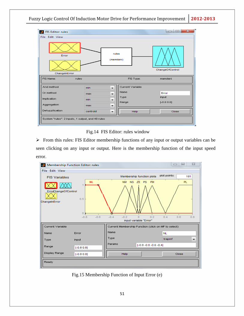
Fig.14 FIS Editor: rules window
From this rules: FIS Editor membership functions of any input or output variables can be
seen clicking on any input or output. Here is the membership function of the input speed
error.
Fig.15 Membership Function of Input Error (e)
Fuzzy Logic Control Of Induction Motor Drive for Performance Improvement 2012-2013
52
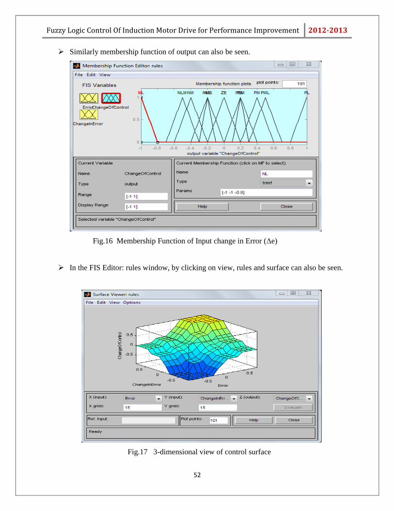
Similarly membership function of output can also be seen.
Fig.16 Membership Function of Input change in Error (Δe)
In the FIS Editor: rules window, by clicking on view, rules and surface can also be seen.
Fig.17 3-dimensional view of control surface
Fuzzy Logic Control Of Induction Motor Drive for Performance Improvement 2012-2013
53
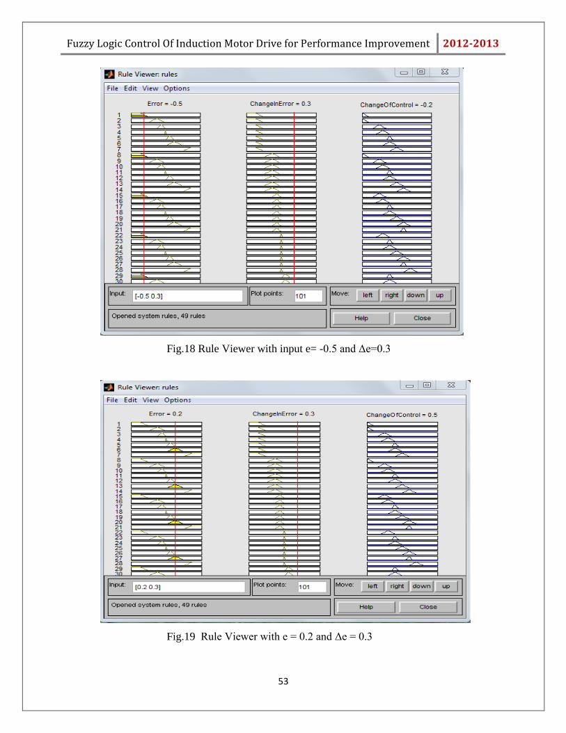
Fig.18 Rule Viewer with input e= -0.5 and Δe=0.3
Fig.19 Rule Viewer with e = 0.2 and Δe = 0.3

Fuzzy Logic Control Of Induction Motor Drive for Performance Improvement 2012-2013
54
7.7 Summary:
Here in this chapter we have designed a fuzzy logic based controller. To design the controller,
first fuzzy set and membership functions are chosen, then rule base is designed. Rules, surfaces
and membership function of input and output variables are also verified in the FIS Editor
window. The controller designed has used the mamdani model with Centroid Of Area
defuzzification technique.
Fuzzy Logic Control Of Induction Motor Drive for Performance Improvement 2012-2013
55
Chapter 8
MATLAB Simulation
Fuzzy Logic Control Of Induction Motor Drive for Performance Improvement 2012-2013
56
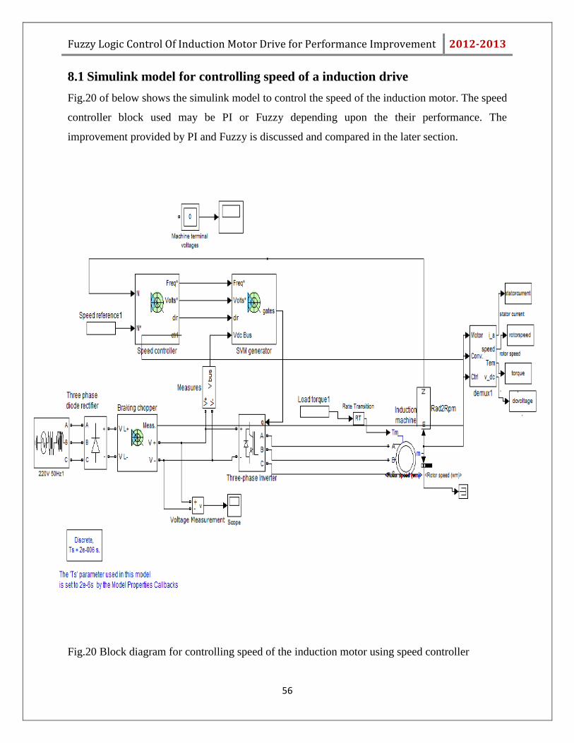
8.1 Simulink model for controlling speed of a induction drive
Fig.20 of below shows the simulink model to control the speed of the induction motor. The speed
controller block used may be PI or Fuzzy depending upon the their performance. The
improvement provided by PI and Fuzzy is discussed and compared in the later section.
Fig.20 Block diagram for controlling speed of the induction motor using speed controller
Fuzzy Logic Control Of Induction Motor Drive for Performance Improvement 2012-2013
57
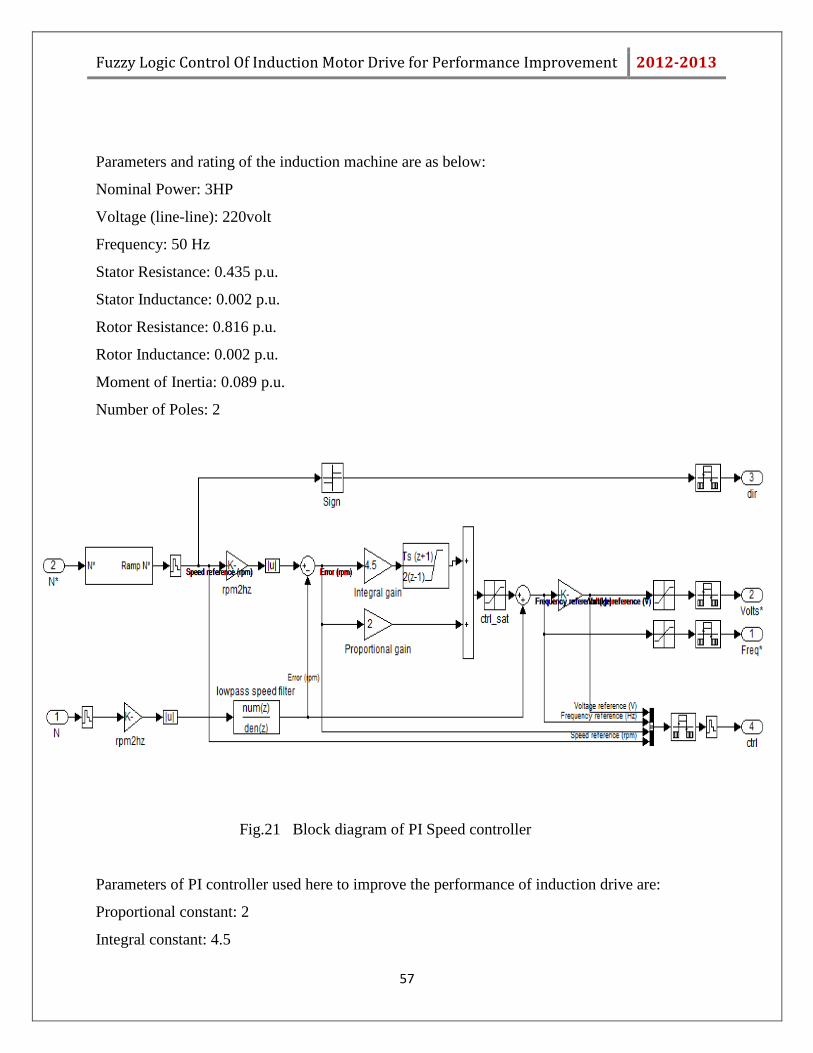
Parameters and rating of the induction machine are as below:
Nominal Power: 3HP
Voltage (line-line): 220volt
Frequency: 50 Hz
Stator Resistance: 0.435 p.u.
Stator Inductance: 0.002 p.u.
Rotor Resistance: 0.816 p.u.
Rotor Inductance: 0.002 p.u.
Moment of Inertia: 0.089 p.u.
Number of Poles: 2
Fig.21 Block diagram of PI Speed controller
Parameters of PI controller used here to improve the performance of induction drive are:
Proportional constant: 2
Integral constant: 4.5
Fuzzy Logic Control Of Induction Motor Drive for Performance Improvement 2012-2013
58
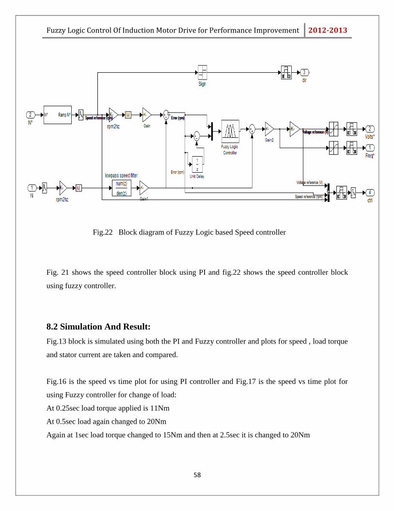
Fig.22 Block diagram of Fuzzy Logic based Speed controller
Fig. 21 shows the speed controller block using PI and fig.22 shows the speed controller block
using fuzzy controller.
8.2 Simulation And Result:
Fig.13 block is simulated using both the PI and Fuzzy controller and plots for speed , load torque
and stator current are taken and compared.
Fig.16 is the speed vs time plot for using PI controller and Fig.17 is the speed vs time plot for
using Fuzzy controller for change of load:
At 0.25sec load torque applied is 11Nm
At 0.5sec load again changed to 20Nm
Again at 1sec load torque changed to 15Nm and then at 2.5sec it is changed to 20Nm
Fuzzy Logic Control Of Induction Motor Drive for Performance Improvement 2012-2013
59
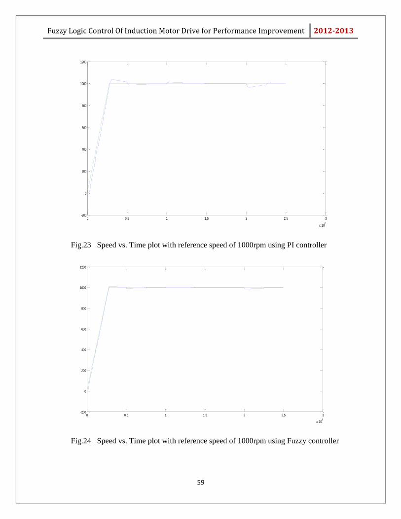
Fig.23 Speed vs. Time plot with reference speed of 1000rpm using PI controller
Fig.24 Speed vs. Time plot with reference speed of 1000rpm using Fuzzy controller
0 0.5 1 1.5 2 2.5 3
x 106
-200
0
200
400
600
800
1000
1200
0 0.5 1 1.5 2 2.5 3
x 106
-200
0
200
400
600
800
1000
1200
Fuzzy Logic Control Of Induction Motor Drive for Performance Improvement 2012-2013
60
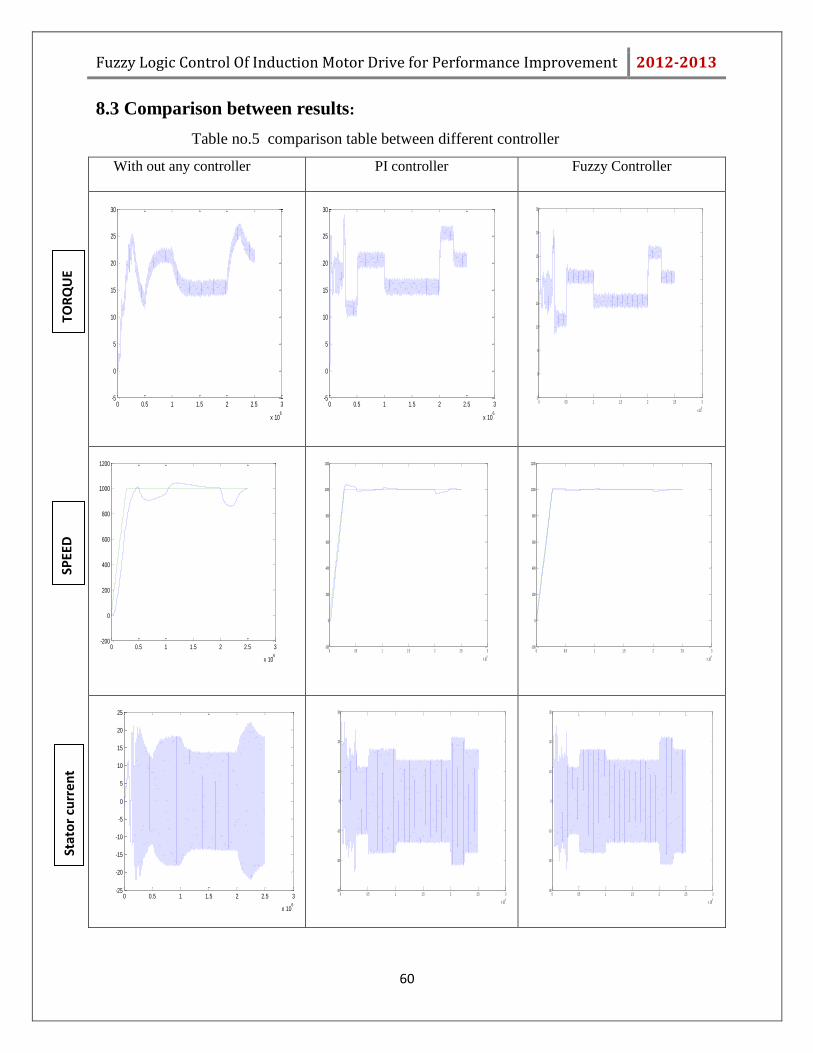
8.3 Comparison between results:
Table no.5 comparison table between different controller
With out any controller
PI controller Fuzzy Controller
0 0.5 1 1.5 2 2.5 3
x 106
-5
0
5
10
15
20
25
30
0 0.5 1 1.5 2 2.5 3
x 106
-5
0
5
10
15
20
25
30
0 0.5 1 1.5 2 2.5 3
x 106
-5
0
5
10
15
20
25
30
35
0 0.5 1 1.5 2 2.5 3
x 106
-200
0
200
400
600
800
1000
1200
0 0.5 1 1.5 2 2.5 3
x 106
-200
0
200
400
600
800
1000
1200
0 0.5 1 1.5 2 2.5 3
x 106
-200
0
200
400
600
800
1000
1200
0 0.5 1 1.5 2 2.5 3
x 106
-25
-20
-15
-10
-5
0
5
10
15
20
25
0 0.5 1 1.5 2 2.5 3
x 106
-30
-20
-10
0
10
20
30
0 0.5 1 1.5 2 2.5 3
x 106
-30
-20
-10
0
10
20
30
Stat
or
curr
ent
SPEE
D
TOR
QU
E
Fuzzy Logic Control Of Induction Motor Drive for Performance Improvement 2012-2013
61
From the above figure it can be easily seen that without using a controller, drop of speed during
load change is very high and also the torque and the stator current is not smoothly varying. It
needs some time to provide the desired torque to the load.
But after using controller, all these problems are solved. Speed drop occurring during load
changes reduced to a great amount and the torque is not much fluctuating and it does not take
much time to change its magnitude and provide the desired torque. Stator current waveform is
also smoothened after using the controller.
When comparing PI controller and fuzzy controller, it can be clearly seen that overshoot is more
in PI controller. Also the settling time is more and it needs more time to reach at the steady state
value. After every load change fuzzy controller based drive reach to the steady state speed of
1000rpm in lesser time as compared to PI controller controlled drive.
We can see that at the starting there is a distortion in current and torque waveform before the
drive reaches to steady state. The reason behind this distortion is the transient during the starting
of induction motor. Other than that part current is entirely sinusoidal and steady. Torque is also
constant with only little oscillation.
8.4 Conclusion:
The fuzzy controller controlled drive is providing better results in improving the performance of
the induction motor than PI controller. Whenever the machine is loaded, the speed of the
machine fell to some extent but this fall in speed is very less in case of fuzzy controller
controlled drive. So we can say that overshoot is more in case of PI controller. And overall we
can say that Fuzzy controller is proving better result than PI controller

Fuzzy Logic Control Of Induction Motor Drive for Performance Improvement 2012-2013
62
Chapter 9
Conclusion
Fuzzy Logic Control Of Induction Motor Drive for Performance Improvement 2012-2013
63
9.1 Comparison between FLC and Conventional Controller: A. Overshoot is high in case of conventional controller.
B. Settling time is also more in case of conventional controller.
C. Conventional controller provides better result for linear system. But as induction motor is
a highly non-linear device, conventional does not guarantee good performance.
D. Fuzzy controller is based on rule base, which is user defined. So it is highly suitable for
induction motor (highly non-linear device) and provides better result than conventional
controller. By using the fuzzy controller in the induction motor drive, motor speed
follows the desired speed with very minimum error.
From the results it is clearly seen and can be concluded that performance of the induction motor
is getting better when controlled by a controller. Speed drop during the load change is reduced to
a great extent. Also the torque and stator current waveform becomes better.
9.2 Discussion:
The main objective or the main concern of this project is to control the speed and provide better
performance with frequent load changes. With this objective we focused to develop a fuzzy logic
based controller with possible precision. For that we have chosen appropriate membership
function and some If-Then rules. Also we tried to tune the controller by slightly changing MFs
and rules.
In this project a Fuzzy Logic based Controller is designed with the help of MATLAB, which can
be utilized in speed control of induction motor. The controller takes numerical input of speed
error (e) and change in speed error (Δe), processes those inputs according to the rule framed and
then provide a output called change in control. All the rules have been verified with the help of
FIS editor rule viewer. Results are also shown for different error and change in error.
After simulating and comparing the results with conventional controller, it is concluded that
fuzzy controller works efficiently for induction motor drive.
Fuzzy Logic Control Of Induction Motor Drive for Performance Improvement 2012-2013
64
9.3 Future Scope:
Both the speed controller block based on fuzzy logic and the block diagram to control the speed
of induction motor using that speed controller is shown in fig.22 and fig.20 respectively. These
blocks are simulated and results are analysed. Also the controller is tuned when needed to
provide desired results.
This control mechanism based on fuzzy logic is not restricted to the induction motor only. It is
applicable and can be used for other areas also. Now days a number of fuzzy logic-based
Precision environmental control systems are also available which are used for applications such
as digital switching sites.
Tuning of fuzzy controller has become easy due to different strategies like Genetic Algorithm.
Fuzzy Logic Control Of Induction Motor Drive for Performance Improvement 2012-2013
65
REFERENCES
[1] J.-S. R. Jang, C.-T. Sun, E. Mizutani, “Neuro-Fuzzy and Soft Computing,” Pearson
Education Pte. Ltd., ISBN 81-297-0324-6, 1997, chap. 2, chap. 3, chap. 4.
[2] Gilberto C. D. Sousa, Bimal K. Bose and John G. Cleland, “Fuzzy Logic Based On- Line
Efficiency Optimization Control of an Indirect Vector-Controlled Induction Motor Drive” IEEE
transaction on industrial electronics, vol 4, no 2, april 1995.
[3] G. El-Saady, A.M. Sharaf, A. Makky, M.K. Sherriny, and G. Mohamed, “A High
Performance Induction Motor System Using Fuzzy Logic Controller,” IEEE Trans. 07803-
1772-6/94, pp. 1058-1061, 1994.
[4] R.Ouiguini, K. Djeffal, A.Oussedik and R. Megartsi, “Speed Control of an Induction
Motor using the Fuzzy logic approach.”, ISIE‟97 - Guimariies, Portugal, IEEE Catalog
Number: 97TH8280, vol.3, pg. 1168 – 1172.
[5] J. Martínez García, J.A. Domínguez, “Comparison between Fuzzy logic and PI controls
in a Speed scalar control of an induction machine,” CIRCE – ge3 – Departamento
deIngeniería Eléctrica C.P.S., Universidad de Zaragoza, Conf. Paper
[6] K.L.Shi,T.F.Chan,Y. K. Yong and S.L.Ho: “Modeling and simulation of three phase
induction motor using Simulink/Matlab”,IEEE trnsactions on industry
applications,vol.37,no.5,September/October2001.
[7] Abdullah I. Al-Odienat, Ayman A. Al-Lawama, “The Advantages of PID Fuzzy
Controllers Over The Conventional Types,” American Journal of Applied Sciences 5 (6):653-
658, 2008, ISSN 1546-9239,pp.653–658.

66