Fuzzy Logic Based Selection Df Machining Parametersdoras.dcu.ie/18835/1/Kashmeri_Hashmi.pdf ·...
188
Fuzzy Logic Based Selection Df Machining Parameters Kashmeri Hashmi M.Sc. 1997 DUBLIN CITY UNIVERSITY
Transcript of Fuzzy Logic Based Selection Df Machining Parametersdoras.dcu.ie/18835/1/Kashmeri_Hashmi.pdf ·...

Fuzzy Logic Based Selection Df Machining Parameters
Kashmeri Hashmi
M.Sc. 1997
DUBLIN CITY UNIVERSITY

FUZZY LOGIC BASED SELECTION OF MACHINING PARAMETERS
A Thesis subm itted in fulfilm ent of the requirem ents for the Degree of M aster of Science
To
Dublin City University
by
K ashm eri H ashm i B.Sc. (Hons) Com puter Science School of C om puter Applications
Dublin City University
. «*
Supervisors : Professor M RyanDr M A El-Baradie
July, 1997
I

DECLARATION
I hereby certify that this material, which I now submit for assessment on the programme o f study leading to the award o f Master o f Science is entirely my own work and has not been taken from the work of others save and to the extent that such work has been cited and acknowledge within the text o f my work
Signed Kj^vtvVvie-Tn i H¿w Lwa i_______ ID No 94970696
Date
l

ABSTRACT /
Selecting cutting parameters for machining is a complex problem A fuzzy logic
based approach to setting these parameters is developed and implemented The
materials data used were for medium carbon leaded steel (BHN 125.-425) and
freemachming carbon wrought steel (BHN 225-425) Three different depths o f cut
(1mm, 4mm and 8mm) and four types o f tools were used for the study, i) High
Speed Steel Tool, 11) Carbide Tool-Coated, 111) Carbide Tool-Uncoated Brazed and
i v ) Carbide Tool-Uncoated indexable
The data used to evaluate the fuzzy model were taken from the Machinability Hand
Book [99] which contams the most appropriate values and ranges used for different
types o f materials in the industrial environment
Two fuzzy models were developed for carrying out these calculations In fuzzy
model- 1, the fuzzy metric arcs are overlapped at 50% and in fuzzy model- 2, the
fuzzymetnc arcs are overlapped at 33%
Computer software was developed to implement the model and to predict the cutting
conditions for the two materials mentioned above The results based on the initial
models were improved by tuning the models further The results were then in
excellent agreement with the machinability hand book The programme as it stands
is applicable for Medium carbon leaded steel and Freemachimng carbon wrought
steel only However, it could be extended to incorporate different work materials
and tool combinations once appropriate data is available

ACKNOWLEDGEMENTS
I would like to express my sincere thanks and gratitude to Dr Mohie El-Baradie for
his supervision, advice and encouragement during this study
I would like to express my sincere gratitude to Professor Michael Ryan, Head,
School o f Computer Applications, for being my supervisor and for givmg me the
opportunity to take up this research work His support, advice and guidance during
the various stages o f the work is greatly appreciated
I would like to thank my husband and children for their support and encouragement
during this study period
Finally, I would like to express my appreciation to Yvonne Patterson, Lesley Lawlor
and Michelle Considme for typing my thesis

TABLE OF CONTENTS
PageDeclaration 1Abstract 11Acknowledgements mTable o f Contents __iv
Chapter 1 Introduction 1
Chapter 2 Literature Survey
2 1 Literature Survey on Application o f Fuzzy Logic 72 11 Introduction
2 12 Application o f Fuzzy Logic in Control System 8
2 13 Application o f Fuzzy Logic m Robotics 10
2 14 Application o f Fuzzy Logic in Industrial Appliance ' 12
2 15 Application o f Fuzzy Logic in Medical Diagnosis 17
2 2 Literature Survey on Machinabihty 18
2 2 1 Introduction 18
2 2 2 Machinabihty Assessment 18
Chapter 3 Fuzzy Logic Theory
3 1 Introduction 25
3 2 Crisp Sets and Fuzzy Sets 27
3 3 Membership Functions 30
3 4 Fuzzy Rules 32
3 5 Fuzzy Partition o f input/output Umverse 33
3 6 Fuzzy Set Operations 34
3 7 Fuzzy Relation 40
3 8 Fuzzy Set Shapes 42
Chapter 4 Machinabilitv Assessment of a Material
4 1 Introduction 45
4 2 Machinabihty 45
4 2 1 Cutting Force 48
4 2 11 Continuous Chip 51
I V

4 2 12 Continuous Chip with Build Up Edge 51
4 2 13 Discontinuous Chip 52
4 2 2 Tool Life 52
4 2 3 Surface Roughness 56
4 3 Effect o f Machining Parameters on Surface Finish _58
4 3 1 Cutting Conditions 58
4 3 2 Cutting Tool Geometry 58
4 3 3 Work Piece Geometry 59
4 3 4 Machine Tool Rigidity 59
4 3 5 Work Piece Material 59
4 3 6 Tool Matenal 60
4 3 7 Cutting Fluid 60
Chapter 5. Development of Fuzzy Models
5 1 Introduction 61
5 2 Data Used 62
5 3 Membership Functions for Metal Cutting 64
5 4 Rule Construction for Fuzzy Model 66
5 5 Fuzzy Relation for Metal Cutting 67
5 6 Theoretical results using Fuzzy (model -1 ) and discussions 75
5 7 Development o f Fuzzy (m odel-2) 114
5 8 Theoretical results using fuzzy (model - 2) and discussions 119
Chapter 6 Fuzzy Software
6 1 Fuzzy Logic Simulation Program for Machining Data Selection 137
6 2 Flowchart o f the Fuzzy Software 139
Chapter 7 Conclusions and Recommendations
7 1 Conclusion 145
7 2 Recommendations for further works 146 -
References
Appendix: Program listing
147

CHAPTER 1 INTRODUCTION
Machinery has become indispensable to the modem world Today, machine tools
form the basis o f our industry and are used directly or indirectly in the manufacture
o f all the products o f modem civilisation Whatever metal is used in any-man-made
object, it must have reached its final stage through processing with machine tools
Even parts made from plastics require metal dies made with machine tools
The origins o f the machine tool industry can be traced to the early days o f stone age,
when men first learned to make round holes in stones using their hands to rotate a
wooden stick pressing sand against the surface being worked upon The history of
bow driven turning lathes, for making wooden ornaments, has been traced as far
back as 5000 B C In 1568, a lathe using a pedal and wooden spring and a tool rest
was m use for making things like plates, flasks, wind instruments etc In the
seventeenth century1, specialised turning shops producing only wooden dishware
were on the scene In the eighteenth century people used water power and horse
power for driving lathes in the production o f highly complicated articles such as
vases, tables, snuff boxes etc The cutting conditions were set by the individuals
based on years o f experience
Machines were made by skilled craftsman over a number o f years But the
requirements o f mass production resulting from the industrial revolution made it
necessary to create machines in order to produce machines Consequently the
developments m machine tool technology became much faster The most rapid
growth o f the machine tool industry and technology has occurred in the twentieth
century
The traditional machining operations include turning, boring, drilling, milling,
grinding etc The principle used in all machine tools is one o f generating the surface
required by providing suitable relative motions between the cutting tool and the
workpiece In machine tool operation two vital concerns of the manufacturing
1 Juneja, B L and Sekhon, G S , “Fundamentals o f Metal Cutting and Machine Tools”, John Wiley & Sons, 1987
1

engineer are production costs and production rates In practice, a high production
rate would probably mean low production cost, but the manufacturing conditions
giving the maximum production rate is generally not identical to those giving the
minimum cost o f production
In general the production o f a component will involve several machining operations
using a variety o f machine tools Given the appropnate tool and cutting fluid, the
cutting conditions to be determined are the cutting speed, the feed rate and the depth
o f cut In any operation, when either the cutting speed or feed rate are increased
while the other condition is held constant, the actual machining time will be reduced
and the tool-wear rate will increase Very low speeds and feeds will result m a high
production cost because o f the cost o f using the machine and operator for the long
machining time Alternatively, very high speeds and feeds may also result in a high
production time because of the frequent need to change cutting tools, and cost may
be high because o f the cost o f frequent tool replacement How to minimise both the
production time and production cost is the manufacturing engineer’s biggest
problem However, experience gamed over the years by the skilled operator has led
to certain empirical rules or guiding principles for choosing the optimum cutting
conditions for a given machining operation
Many researchers in this regard have suggested a machmability data system which
will provide information needed for the automatic selection o f machining data The
purpose of the data system is to generate the recommended cutting speed, feed rate,
and depth o f cut for different cutting tools Systematic collection and storage of
large quantities o f data from laboratory and industry has resulted in the so called
“Machmability hand book” which provides recommended cutting speeds, feed rates,
and depths o f cut for any specific cutting tool Data from industry are reliable in the
sense that it has been used successfully in practice Workpiece materials are
grouped according to their material Bnnell Hardness Number (BHN) Using the
machining hand book for choosing cutting conditions for material hardness that lies
at the middle o f the group is simple and straight forward But there exists a degree
o f vagueness for the boundary cases, where two choices o f cutting speeds are
applicable for one choice o f matenal hardness In this situation, the skilled operator
decides the appropnate cutting speed based on years o f experience However this
2
)

method o f choosing data by the individual operator is not desirable, because it may
vary from operator to operator It is desirable to have an operator independent
system for consistent machimng operation
The mam objectives o f the present research are -
1 - To investigate the application o f fuzzy logic for machimng data selection
2 - To develop fuzzy models for machimng medium carbon leaded steel and free
machining carbon wrought steel
3 - To develop a computer system based on the principles o f fuzzy logic for
automatic selection of machining parameters
The work programme o f this project is outlined m the following diagram
3

method o f choosing data by the individual operator is not desirable, because it may
vary from operator to operator It is desirable to have an operator independent
system for consistent machimng operation
The mam objectives o f the present research are - _
1 - To investigate the application o f fuzzy logic for machimng data selection
2 - To develop fuzzy models for machining medium carbon leaded steel and free
machining carbon wrought steel
3 - To develop a computer system based on the principles o f fuzzy logic for
automatic selection o f machining parameters
The work programme of this project is outlined in the following diagram
3

Application of fuzzy logic for machining data selection
work-matenal
TheoreticalInvestigation
- Cutting Tool
- Depths o f cut
Application o f fuzzy model
Softwaredevelopment
medium carbonleaded Steel (125-425) BHN
high speed steel carbide tool coated carbide tool uncoated brazedcarbide tool uncoated indexable
1mm, 4mm, 8mm
model 1-fuzzy sets overlapped by 50% model -2 fuzzy sets overlapped by 33%
free machining carbon-wrought Steel (225 - 425) BHN
high speed steel carbide tool coated carbide tool uncoated brazedcarbide tool uncoated indexable
1mm, 4mm, 8mm
model-1, fuzzy sets overlapped by 50%
automatic data selection
automatic data selection
Output (Recommended cutting conditions)
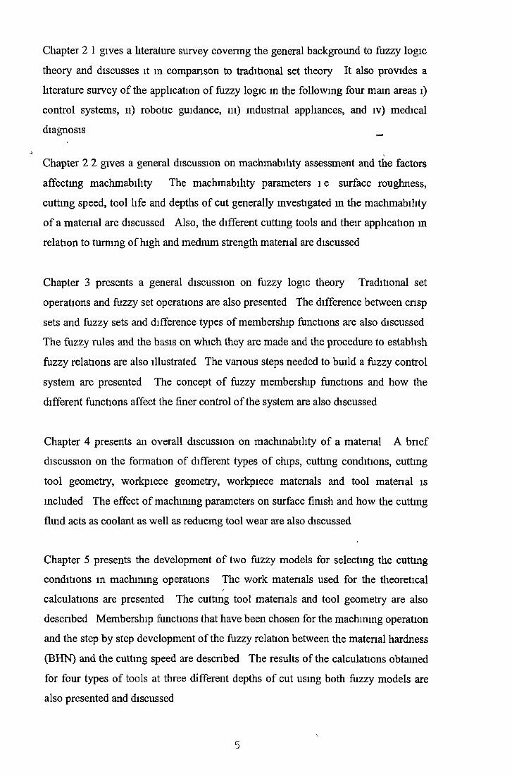
Chapter 2 1 gives a literature survey covering the general background to fuzzy logic
theory and discusses it in comparison to traditional set theory It also provides a
literature survey o f the application o f fuzzy logic in the following four mam areas 1)
control systems, 11) robotic guidance, 111) industrial appliances, and i v ) medical
diagnosis __
Chapter 2 2 gives a general discussion on machmability assessment and the factors
affecting machmability The machmability parameters l e surface roughness,
cutting speed, tool life and depths o f cut generally investigated m the machmability
o f a matenal are discussed Also, the different cutting tools and their application in
relation to turning o f high and medium strength matenal are discussed
Chapter 3 presents a general discussion on fuzzy logic theory Traditional set
operations and fuzzy set operations are also presented The difference between cnsp
sets and fuzzy sets and difference types o f membership functions are also discussed
The fuzzy rules and the basis on which they are made and the procedure to establish
fuzzy relations are also illustrated The vanous steps needed to build a fuzzy control
system are presented The concept o f fuzzy membership functions and how the
different functions affect the finer control o f the system are also discussed
Chapter 4 presents an overall discussion on machmability o f a matenal A bn ef
discussion on the formation of different types o f chips, cutting conditions, cutting
tool geometry, workpiece geometry, workpiece matenals and tool matenal is
included The effect o f machining parameters on surface finish and how the cutting
fluid acts as coolant as well as reducing tool wear are also discussed
Chapter 5 presents the development o f two fuzzy models for selecting the cutting
conditions in machining operations The work matenals used for the theoretical
calculations are presented The cutting tool matenals and tool geometry are also
descnbed Membership functions that have been chosen for the machining operation
and the step by step development o f the fuzzy relation between the matenal hardness
(BHN) and the cutting speed are descnbed The results of the calculations obtained
for four types o f tools at three different depths o f cut using both fuzzy models are
also presented and discussed
5

Chapter 6 presents the fuzzy logic simulation program that has been developed for
selecting cutting conditions m machining operations A brief description about the
program and how to use it is also presented
Finally, conclusions and recommendations for further work are discussed m
Chapter 7
6

CHAPTER 2 LITERATURE SURVEY
2. 1. Literature Survey of F u z z y Logic
2 . 1.1 Introduction
Fuzzy set theory was developed in 1965 by Lotfi Zadeh [1] o f the University o f
California at Berkeley. Most o f the traditional tools for formal modelling, reasoning
and computing are crisp, deterministic and precise in character. By crisp is meant
that attributes are of the ‘yes’ or ‘no’ rather than the ‘more’ or ‘less’ type. In
conventional logic, for instance, a statement can be true or false, but not in between.
An element is a member o f a certain set or not. The binary logic used in traditional
set theory has proved very effective and successful in solving many well defined
problem, where descriptions o f the process is being dealt with in quantitative form.
But real situations are very often not crisp and deterministic and cannot be described
precisely. Fuzzy set theory can be viewed as one approach to deal with these kind of
problems. L. Zadeh [1] introduced fuzzy sets as an extension to traditional set
theory and also developed the corresponding fuzzy logic to manipulate them. Lack
of crispness is an aspect o f many real world properties, and fuzzy logic allows us to
define the linguistic terms to name these properties. Over the past few decades,
fuzzy logic technology has been successfully applied in many industrial control
applications, especially since dedicated fuzzy logic processors started becoming
available in the 1980’s. The framework provided by fuzzy sets is perhaps the most
natural and accurate currently available for dealing with non-crisp properties. Its
major advantage is that it allows the description o f a system and its desired
performance in linguistic terms rather than in terms o f relationships between precise
numerical values. Since about 1985 there has been a strong growth in its use for
dealing with problems o f control, particularly in non-linear, ill-defined, time-varying
and complex situations. Various hardware products aimed at speeding up the
computations involved have appeared on the market. As a result, fuzzy logic based
control has boomed and has been applied in many areas, including subway
operations, automobile transmissions, object tracking, camcorder focusing, TV
colour tuning, washing machine automation, robot guidance, image processing,
character recognition and so on.
7

Application of fuzzy logic theory in the following four areas are described below.
1. Application o f fuzzy logic in control system
2. Application o f fuzzy logic in robotic guidance
3. Application o f fuzzy logic in industrial appliances
4. Application o f fuzzy logic in medical diagnosis
2.1.2 Application of Fuzzy Logic in Control System.
More than 2 decades ago, Professor L. A. Zadeh [1] o f the University o f California
published the first paper on fuzzy set theory. In 1980, about a dozen years later,
Smith Corp. in Denmark produced a fuzzy controller for a cement kiln.
Subsequently, many other developers in Japan and elsewhere constructed controllers
on an experimental basis, and now the concept enjoys widespread recognition for its
usefulness. Fuzzy logic is increasingly being incorporated in systems to provide
robust and effective control in a wide range of applications.
Sukvittayawong and Inasaki [2] have proposed a system for identifying chip form in
turning processes in an unmanned situation. Fuzzy set theory and neural networks
are applied to identify the chip form. The results o f the interaction between
workpiece, tool and machine tool are continuously monitored so that any change in
the turning environment can be sensed in order to take corrective action. The system
also used acoustic emission signal analysis to identify the chip form during cutting.
In experiments the percentage o f correct identification o f chip form using both the
methods is always higher than 90%.
Lewis, [3] presented a paper in 1994 where he described the implementation of
fuzzy logic (FL) as a new technique based on microprocessor capabilities that
enables control devices to ‘think’ more like humans. This capability helps to
automate systems that previously required constant monitoring and intervention. He
also expressed the view that since FL uses English syntax programming, it reduces
the size o f software programs and lets engineers develop control system in as little as
1/10 the time o f conventional methods.
8

Wang and Birdwell, [4] have developed a new fuzzy - PID controller, which
merged PID control and fuzzy control in order to improve system performance
especially when uncertainty and complexity are involved The proposed model
provided a mechanism to achieve PID controller selftunmg and encoded different
control strategies for use under different circumstances in fuzzy rulebases It has
been suggested that the derived controller can always equal or better the
performance o f any PID controller The new structure was implemented for several
plants and demonstrated significant improvements in system performance
Wang et al [5] have developed a fuzzy tracking system for rotation-invariant image
tracking A dual template strategy was proposed and only two parallel matched
filters and a simple fuzzy logic system were employed to construct the novel fuzzy
tracking system The experiments showed that the system can track the target more
accurately and rapidly and also less expensively than the conventional rotation-
invariant methods
DeCorte et al [6] reported that Cybermotion Inc has proved that the idea of dual-use
technology worked with their security robot the SR2 Due to the decreasing
overhead and since increasing security is always beneficial for both government and
the commercial world, this has led to the development o f an autonomous security
robot equipped with a fuzzy logic certainty system This robot with its fuzzy logic
system can furnish a significant and cost-effective safety function
Dhawan, [7] et al have developed a expert-fuzzy system called COGSA (core
geometry selection aid), which is a combination o f expert system and fuzzy logic
techniques for selecting optimum core geometry and core size for high frequency
power transformers COGSA aids the magnetic designer m the selection o f a core
geometry, taking into account various decision components such as power, cost,
heating and shielding in the form of IF-THEN statements Fuzzy rules were
manipulated by a forward chaining method and fuzzy logic was applied to consider
the uncertainty involved with the various factors. COGSA operates under the
Microsoft windows operating system, gathering inputs from the user and then
9
processes these inputs and displays the final output both numerically and in a
graphical form
Xiong and Holdtich, [8] earned out an investigation into the application o f fuzzy
logic to oil and gas well stimulation treatment design It has been concluded that
fuzzy logic theory can be used to build evaluators to help an engineer to select the
optimal stimulation
Gondo et al [9] have installed a paired crossed roll mill in no 1 Hot Stnp Mill in
NKK Fukuyama works in Japan m order to control hot stnp crown and flatness
effectively Mathematical models were developed using fuzzy logic and have been
applied to an on-line process control computer system They have reported that stnp
crown can be controlled accurately with this new fuzzy control system
Wong et al [10] have incorporated a senes o f fuzzy logic based algonthms for
recognition and classification o f the defects on high mtegnty casting surfaces
Fuzzy logic memberships were generated for the detection o f defects found on
casting surfaces Simulated model shapes o f quench cracks and mechanical cracks
were used to test the generated algonthm Results for recognition and classification
were very encouraging and they obtained very good results
2.1.3 Application of fuzzy logic in Robotics Guidance.
The Application o f fuzzy logic to robotics was first conducted by Uragami et al [11]
in 1976 The robot controls were based on fuzzy programs The fuzzy program
[11] were defined as an ordered sequence o f fuzzy instructions In the fuzzy
program, fuzzy instructions are translated into machine instructions by the use o f
max-method and back-trackmg
Similar work on robots was also reported by Goguan [12] Fuzzy linguistic hints
were used to aid a robot running through a maze
In 1985 a robot with a knowledge base o f movement was studied by Hirota et al
[13] The knowledge base is mainly composed o f control rules in terms of
probabilistic sets in extended fuzzy expressions The ambiguous instructions in
1 0

terms o f membership and vagueness are given to the robot and then the robot is able
to recognise these instructions and select an appropriate movement
Also in 1985, Scharf et al, [14] presented a fuzzy self organising controller (SOC)
for a robot arm The SOC consists o f the rule base, the performance matrix, rule
reinforcement and the history buffer Experiment shows that the performance o f the
SOC is superior to a conventional PID controller Further work on the SOC based
on fuzzy logic was earned out by Tanschett and Scharf [15] In the improved SOC,
the input signals, which are mapped to one o f 13 discrete levels, are processed by
using the rule-based control algonthm The output signals, m a linguistic form, are
mapped to a real value
In 1991 Kouatle and Jones [16] developed a fuzzy controller for a robot welding
system The objective was to control the speed of the robot arm to carry out the
welding process in the same manner as the human welding operator A scale for
partitioning the universe o f discourse was determined by using the expert’s
knowledge The fuzzy reasoning was based on a compositional rule o f inference
The speed of the robot arm controlled by the fuzzy logic controller vanes with the
cavity size o f the workpiece bemg welded
Sandis [17-19] has used a fuzzy logic based controller to construct linguistic
decision modules for intelligent robots The intelligent fuzzy logic controllers
proposed by Ray et al [20] have potential impact on future intelligent robots As
suggested in [20], under normal operating conditions the controller will receive
information from regular observations o f plant data and select a suitable control
strategy using the compositional rule o f inference Under abnormal conditions,
normal control actions are modified using a knowledge based decision theoretic
scheme
Chen and Tsao [21] have earned out the global analysis o f fuzzy dynamical systems
By using this method, approximate prediction o f the behaviour o f a fuzzy logic
controller can be achieved

The first fuzzy logic chip was designed by Togai and Watanabe [22] m 1985 These
fuzzy logic chips and computers [22-25] have been developed to speed up the fuzzy
inference processing The inference mechanism embedded in the VLSI chip is the
max-min logic operation A fuzzy logic accelerator (FLA) and fuzzy processor
based on this chip are also available now (26,27) _
In 1986, Yamakawa and Miki [23] developed basic fuzzy logic functions usmg the
standard CMOS process in current-mode circuit system
In 1990 Lim and Takefuji [25] pointed out that incorporating reasoning systems in
hardware is significant because expert system have to take a decision in real-time
Reasomng system hardware for a fuzzy processor system requires developing two
stages defining the fuzzy reasomng algorithm and designing special-purpose
hardware
These fuzzy chips and computers will speed up the application of fuzzy logic
controllers to intelligent robot systems
2.1.4 Fuzzy Logic in Industrial Applications
In 1992 Quail and Adnan [28] have provided an excellent review of the wealth o f
industrial product and consumer appliances that are bringing fuzzy logic application
to the market place In their paper they presented the state-of-art m appliance
technology usmg fuzzy set theory It has been suggested that in the house o f the
future, fuzzy logic will be commonly used in household appliances which will
automatically adjust to room factors such as the number o f people present,
temperature and light levels or even the cleanliness of the floor and m some cases,
the appliances will even operate themselves They commented that fuzzy logic has
helped bring these dreams to the achievable present It appears that this theory has
entered many aspects o f Japanese life and even some areas in the U S such as
automotive [29, 30, 31, 32, 33] air and spacecraft [40] and even the stock exchange
[31, 32, 34] The concept o f the fuzzy-controlled future home has already appeared
in Japanese trade shows and households Numerous appliance applications use

fuzzy logic to achieve design goals First goal is that the appliance be simple to
operate The second is that the appliance have a short development time The third
is that the appliance be cost effective compared to its standard logic counterpart and
finally the design should be dynamic, with the ability to adjust to new inputs and
different users _
Dr Zadeh could not have foreseen the electronic revolution that his obscure fuzzy
set theory has produced However, soon he predicts fuzzy logic will be part o f every
appliance “We’ll see appliances rated not on horse power but on IQ” [35] In
Japan, the revolution has been so strong that “fuzzy” has become a household word
[36] The Japanese use the term positively to denote intelligence Almost all
electronic products are based on fuzzy technology [37] “In Japan, electronics
goods with fuzzy logic are already so popular that it seems to me that those that do
not offer fuzzy applications withm a few years will not be able to survive” [38]
The growing trend is to streamline housework and to use the available time more
effectively Appliances with fuzzy logic controllers provide the consumer with
optimum settings that more closely approximate human perceptions and reactions
than standard control systems Products with fuzzy logic monitor user-dictated
settings then automatically set the equipment to function at the user’s generally
preferred level for a given task [39] The technology is well suited to making
adjustments m temperature, speed and other control conditions found in a wide
variety o f consumer products [38]
The following paragraphs discuss fuzzy logic as applied to various appliances
Washing Machine and Dryer
In 1991, in a journal o f Electromcs Industry, w as1 described a basic neuro-fuzzy
washing machine which uses sensors for water temperature and fabnc type, then
automatically selects one o f 250 modes These washing modes optimise water
temperature, water level, washing and cycle time and spm-drying time [38,41, 42]

The Sharp Domestic Appliance Manufacturer took a different step to make a
variation on the basic machme that shoots bubbles into the wash to completely
dissolve detergent The efficiency o f this machme is increased by 20% over non-
fuzzy machines, as claimed in a Japanese consumer electronics report in 1991 [43]
Some models go a step further These models are equipped with two optical sensors
that can sense the quality and quantity o f dirt m the wash [44, 45] The pair o f
sensors determine the degree of soiling from the wash waters turbidity and also
whether the stain was caused by oil or mud They also discriminate between liquid
or powder detergents and meter the amount o f detergent required [46] The fuzzy
controller analyses the accumulated data and then selects the most efficient cleaning
method from approximately 600 possible choices [45, 47]
The companion dryer uses three heat sensors that monitor load size, fabric type and
hot-air flow The fuzzy controller determines the optimum drying time, shutting
itself off when the contents are dry [46,48], thus saving on time and energy costs
V acuum C leaner
Mitsusada has described in the Japanese Economic Journal in 1996 [42] that the
basic fuzzy logic vacuum cleaner uses a single sensor to judge the amount o f dust
and the floor type By momtonng the change m dust, the controller decides whether
the floor is bare, where the dust comes up at once, or thick-pile carpeting, where the
dust is gradually released Based on that data, the fuzzy controller correlates the best
suction power and beater-bar speed for each specific job For example when a hard
floor is detected the motor and beater-bar are slowed because not much suction is
needed [49]
In addition to analysing the floor type and amount o f dust, the neuro-fiizzy version
also analyses the type o f dirt This information is used to adjust both the suction
power and brush rotation speed for a 45% increase in cleaning speed [48] The
efficiency and power savings m these cleaners is greatly increased over conventional
vacuums Another variation o f the basic fuzzy model is the Toshiba vacuum which
advertises power steering along with all o f its fuzzy features [35]
1 4
2

Microwave Oven
According to Remich and Norman [46] the basic fuzzy-logic microwave oven uses
three sensors infrared, humidity and ambient temperature The sensors monitor the
temperature o f the food and oven cavity as well as the amount o f steam emanating
from the food [46] Based on this information, the fuzzy controller performs
calculation on the type, size and weight o f the food, whether it is frozen or thawed,
whether the oven had been used immediately beforehand and the degree o f
“aloneness” The system results in the most efficient cooking time and usage o f
cooking condition such as roasting or hot-air-blower [46, 50] All o f the
microwaves advertise one touch operation and use fuzzy logic to simulate a cook’s
best judgement [50]
Refrigerator
Fuzzy logic has been used in Kenmore’s premier model to determine the most
efficient time to defrost as descnbed by Rogers and Hoshai in 1992 [35] But Sharp
has taken this application o f fuzzy logic much further This model uses a neuro-
fuzzy logic control system that learns the consumer’s usage patterns for optimum
operation [51]
The Sharp refrigerator memorises the time and frequency o f freezer door and drawer
openings When the usage pattern is learned for each compartment, the fuzzy
control system automatically begins a cooling cycle before heavy traffic periods
This feature minimises temperature fluctuations m the compartments [51]
Based on the memorised information, the unit also chooses the most appropriate
time o f day to defrost [52] An additional feature tells the unit not to make ice at
night which may disturb light sleepers The consumer pushes a button on the unit
before going to sleep m the night and the system memorises this time and repeat this
pattern every night [51]

Air Conditioner
The application o f fuzzy logic to air conditioners was first conducted by Mitsubishi
heavy industries in October 1989 The system uses 50 fuzzy rules, max-product
mferencmg and centroid defuzzification methods A thermistor was used to detect
room temperature and to control the inverter, compressor value, fan motor and heat
exchanger The results from both the simulation and production showed (compared
to the standard system) a 20% reduction in heating and cooling times, a two-fold
increase in temperature stability and an overall power saving o f 76% for the
simulation and 24% in production
Newer models have sensors that evaluates the shape/size o f a room and the
inside/outside temperature and humidity levels By using an infrared sensor, the unit
also determines the number o f people present and cools the room accordingly [35]
These inputs are used by the fuzzy controller to balance the room temperature with
the power needs o f the house resulting in the greatest possible efficiency [36, 42]
Dishwasher
In 1990 Reid [36] has applied fuzzy logic to dishwasher control This fuzzy
appliance detects the number o f dishes loaded and the amount and type o f food
attached on the plates The fuzzy controller efficiently vanes the soap, water and
cycle time based on these data
Rice Cooker
In 1990 the application of fuzzy logic to a nee cooker was conducted by Johnson,
[53] This nee cooker uses three sensors to monitor the steam temperature and the
volume o f nee A similar work on a nee cooker was also reported by Remich, et al
m 1991 [46] and 1992 [48] Once a minute, the sensors are checked and the
remaimng cooking time is calculated The unit has four pre-programmed settings
for different types o f nee such as white, pomdge, glutinous (sticky) and mixed
vanety

Toaster
The application of fuzzy logic to a toaster was also conducted by Reid [36] in 1990.
This particular toaster with fuzzy logic inside was termed “smart”. The toaster
adjusts the heat and toasting time depending on the type o f bread it senses in the
toaster. The user’s preferences are also learned and memorised.
2.1.5 Application O f Fuzzy Logic In M edical Diagnosis
Weinberg and Breggear [1991] [54] have applied a fuzzy set data base search
methodology for the modelling o f adverse animal reaction in drug research. The
model utilises a mathematical fuzzy set algorithm to identify links between the
molecular structure o f a new compound and regressively related molecular structures
o f compounds with known adverse animal reactions. Initial predictive trials have
shown a reliability in excess o f 95% and it has been concluded that fuzzy set
algorithms and the regression approach represent a highly promising and
immediately applicable alternative to live animal research in pre-investigatory new
drug (pre-IND) pharmaceutical development settings.
Meier et al, 1992 [55] have used a fuzzy logic controller to control mean arterial
pressure (MAP) which was taken as a measure o f the depth o f anaesthesia. The
main reason for automating the control o f depth o f anaesthesia is to release the
anaesthetist so that he or she can devote attention to other tasks as well - such as
controlling fluid balance, ventilation and drug application - that cannot yet be
adequately automated and thus to increase the patient’s safety. The model used a
rule-based controller and the design process was interactive with the membership
functions as well as the linguistic rules determined by trial and error.
Tsutsui, and Arita, [56] have constructed a closed-loop blood pressure control
system using fuzzy logic during enflurane anaesthesia. Four fuzzy rules were
constructed, based on published anaesthetic values to determine the relationship
between the changes o f input variables and output values. Anaesthetic control
started with the first map and was maintained with the succeeding maps. It has been
claimed that during anaesthesia, the systolic blood pressure (SBP) remained within
plus or minus 20% of the preanesthetic SBPs in 82% of the fuzzy control cases and
1 7

withm 83% during manual control The difference was not significant The
anaesthetist’s management o f the administration o f the inhaled anaesthetic enflurane
was imitated by fuzzy logic control o f the blood pressure
2.2 L itera tu re Survey O f M achinabilitv. , —
2.2.1 Introduction.
A good amount o f work regarding the machining o f high to mild strength materials
has been reported so far The following review is based on the turning o f mild and
high strength material
The following review is m relation to the surface finish, tool life, and cutting speed
obtained during turning of mild and high strength materials
2.2.2 M achinabilitv Assessment
Shaw and Nakyama [57] have discussed in great details the important aspects
involved m machining various materials In summary, they suggest that for
machining high strength matenals, the tool should be refractory to avoid plastic
flow, have high wear resistant to avoid wear and have good brittle fracture resistance
to avoid chipping
Taraman [58] has developed some mathematical models for cutting force, surface
finish and tool life in terms o f cutting speed, feed and depth o f cut The tests were
earned out under dry conditions and he developed the following equations based on
the expenmental results
Fc = 560V •“16 / ° 775 d 0 665
T = 24949 V '1 406 / 0 248 d 0177
R = 4626 V -0 363 / ' 1371 d 01835
Where Fc is cutting force (N) V is cutting speed (m/mm)
T is tool life (Hours) f is feed ra te (mm/rev)
R is surface roughness d is depth of cut (mm)
)
From these equations it has been concluded that a reduction in all the investigated
outputs (cutting force, surface roughness and tool life) is achieved with increase in
the cutting speed But if the feed increases, the surface roughness and cutting force
increases while the tool life is reduced An increase in the depth o f cut reduces tool
life and causes an increase in surface roughness and cutting force It has also been
noted that feed effect is dominant on surface roughness and the tool life is affected
most by cutting speed, less affected by feed rate and least affected by depth o f cut
Chang and Fuh [59] have studied the cutting performance m turning plain carbon
steel using three kinds o f tools 1 e TiN-coated, TiCN-coated and uncoated cemented
carbide tools with chamfered mam cutting edge (CMCE) They have also used pure
alumimum to study the mechanism o f secondary chip formation A special tool
holder and its geometry was designed for carrying out this study In the overall
performance, the coated CMCE tools were better than the uncoated CMCE In
regard to the cutting force, the surface roughness o f the work piece and the
temperature o f the tip surface, the levels o f coated CMCE tools were all smaller than
for the uncoated ones The cutting force for the TiCN-coated CMCE tools was
smaller than that o f the tm-coated ones From the surface roughness o f the work
piece, the tm-coated CMCE tools showed better results From the colour o f the mam
chip and the hardness o f the secondary chip, the temperature o f the secondary chip
was determined to be higher than that o f the mam chip
Research was conducted by Lin et al [60] to study the machinability o f a silicon
carbide reinforced aluminium metal matrix composite Continuous turning o f round
composite bars using tools with 25mm polycrystalline diamond (PCD) inserts was
selected as the test method Various cutting speeds and feed rates were selected for
the test while depth o f cut were kept constant The performance o f the tools was
based on development o f 0 25mm maximum flank wear, which were monitored by
optical and scanning electron microscopy They have found out from their test
results that the time required to reach the tool wear limit decreased with the
increases o f speed and feed However, the volume o f maternal removed before
reaching the wear limit actually increases with the higher feed rate
1 9

Wilson and El-Baradie [61] carried out a number of turning tests on Vitallium, a
cobalt base alloy, to investigate cutting forces, tool wear and surface finish using
carbide and cubic boron nitride (CBN) inserts having three different rake angles.
The test result showed a very high cutting forces up to 1000 N at a feed rate o f
0.08mm/rev and a depth of cut 0.25mm. Smallest cutting forces resulted from using
the cutting tool with a positive rake angle. The wear o f carbide tool with negative
rake angle and low cutting speed (<20m/min) was a combination o f adhesive,
abrasive and diffusive wear. With CBN inserts, flank wear curves did not show the
three distinctive zones (initial rapid wear, steady wear, and final abrupt wear). They
noticed when the cutting speed was in excess o f 30 m/min, the surface finish
produced by the carbide tool was improved. The surface finish using CBN tools was
extremely good.
Huet and Kramer [62] and Wright and Chow [63] have conducted some researches
to find the relationship between the cutting speed and temperature o f the cutting
edge during machining of nickel alloys such as inconel 718 and nimonic 75. Their
test result showed that at low speeds, the rate o f increases o f temperature o f the
cutting edge was very high and as the speed increased, this gradient was found to
decrease.
Albrao et al [64] presented tool life data for various grades of conventional ceramic
and PCBN cutting tool materials when turning hardened AISI H I3 hot work die
steel - (52 HRC) and hardened AISI E52100 bearing steel (62 HRC). They also
evaluated in details some aspects o f surface integrity following roughing and
finishing operations. Their test include 3D mapping o f surface texture and analysis
o f microstructure and microhardness variation. These test results indicated that
when maching the hot work die steel and finishing the bearing steel low
concentration PCBN and mixed alumina tooling provided the longest tool lives.
Dam et al [65] carried out a general survey o f the processes that govern the
ultrasonic maching o f ceramics. The experiments were carried out by drilling holes
in seven different ceramics and the aspects considered were production rate, tool
20

wear, precision and surface quality. In their investigation they found that tough
materials gave a low production rate, a high tool wear and a low surface roughness.
For brittle materials the relationships were reversed - that was high production rate,
low tool wear and high surface roughness. However they came to a conclusion that
there were important quantitative differences in the machined surfaces. Generally
tough materials gave material removed based on plasticity, and there seemed to be a
greater tendency for dense and non-porous materials to produce surfaces with
texture.
Komanduri and Schroeder [66] have produced machining conditions between the
cutting speed and the chips formed from their maching test o f high strength material
(400 BHN). At lower speed (< 30 m/min), the chips were continuous and coiled
while shear localization o f the chip began at speed between 30 to 90 m/min and the
segments were joined together in long coils. Isolated segments o f chips were formed
when the cutting speed was above 150m/min.
Sadat [67] conducted some experiments using natural and controlled contact length
at various cutting speeds under dry and lubricated conditions to machine high
strength material such as inconel 718 (38 RC) to examine the surface characteristics.
He selected a constant feed rate (0.01 mm/rev) and four levels o f cutting speed (6.6,
18, 36 and 60 m/min) for these tests. For a given cutting speed, both the tangential
and feed forces were lower under controlled contact length o f 0.15mm as compared
to 0.39mm contact length. These tool forces decreased with an increase in cutting
speed. The effect o f lubrications on the tool forces was negligible at high speed
cutting and the forces decreased with the increase o f cutting speed.
Investigation was carried out by Dontamsetti and Fischer [68] to find out the factors
affecting surface roughness in finish turning of grey cast iron (195 BHN). They
used uncoated tungsten carbide inserts. Four levels o f cutting speed and feed rate,
two levels o f nose radius and three levels o f tool were used as independent variables.
The cutting speed, feed and nose radius had significant affect on surface roughness.
Interactions between tool wear and each o f the other three variables were also highly
significant.
21

Lim [69] has investigated the wear on the tool for an effective unmanned machine-
turning system. He suggested that changes in the tool wear can be detected in the
vibration signatures during the machine turning operation. It was found that at
various cutting speeds, the vibration amplitudes consistently produce Jw o peaks
throughout the life o f the tool and also there was a strong correlation between the
tool flank wear and the acceleration amplitude. He suggested that this signal can be
incorporated in a software program for an on-line monitoring system to indicate the
onset o f tool failure thus assessing the life o f the cutting tool and also improving
cutting performance.
Mital and Mehta [70] conducted an experiment to collect surface finish data for a
wide variety o f metals and alloys (aluminium alloys 390 (71.5 BHN), ductile cast
iron (183 BHN), medium carbon leaded steel 10L45 (197 BHN), medium carbon
alloy steel 4130 (195 BHN) and inconel 718 (340 BHN) for a wide range of
machining conditions. They used a randomised complete block factorial design with
four levels o f feed rates (0.0508, 0.127, 0.2032 and 0.3048 mm/rev) and three nose
radii (0.794, 1.190 and 1.587mm). Three levels o f cutting speeds (243.8, 304.8 and
365.7 m/min) and (167.6, 213.4 and 259.1 m/min) were used for machining tests of
medium carbon leaded steel 10L45 and medium carbon alloy steel 4130
respectively. In case o f medium carbon leaded steel 10L45 the surface finish
improved significantly with tool nose radius (p > 0.01), but deteriorated with feed
(effect significant at less than 1% level). The effect o f speed was mixed and the
surface finish improved as the cutting speed increased to 304.8 m/min. In case of
medium carbon alloy steel 4130 the results were similar to those obtained for
medium carbon leaded steel 10L45. The results o f their study indicated that the
machining conditions for different metals significantly influenced their surface
finish. The effect o f feed was found to be more profound than either the effect o f
cutting tool nose radius or the effect o f cutting speed. They suggested that it helps to
employ a cutting tool with larger nose radius - because the surface finish improved
with the tool nose radius. In their investigation the negative and positive
correlation’s between speed and surface finish for different metals indicated that the
generalisation that higher speeds always lead to superior finish is invalid while
22
surface finish may improve with speed for some materials, it may deteriorate for
others. Similar conclusions were drawn by Karmaker 1970 [71] for medium carbon
steel, using ceramic tools and Chandiramani and Cook 1964 [72] for leaded and
resulphurized steels, using carbide tools.
Yaguchi [73] carried out a set o f experiments to measure the cutting forces and to
observe chip morphology in hot and cold drawn bars o f AISI 12L14 steel. The
cutting force o f cold drawn bars was found to be significantly lower than that o f hot
rolled bars, whereas only slight difference were detected in chip thickness.
Ohtani and Yokogawa [74] have investigated the wear mechanism of the cubic
boron nitride (CBN), ceramic and carbide tools and cutting forces encountered
when turning tool steel having several levels of hardness ranging from 18R,. - 601^.
A constant depth o f cut 0.2mm and feed rate o f 0.1 mm/rev and three levels o f
cutting speeds (100, 150 and 200 m/min) were used under dry condition. They
found that the life span of carbide tools decreased as the hardness of the workpiece
increased, while the life span o f CBN and ceramic tools showed the opposite results.
They also found the tool failure for CBN and ceramic was abrasion wear by hard
alloy carbide particles contained in the workpiece. The increasing rates o f cutting
force components against flank wear were slower for carbide tools than for the other
tool. They concluded that the stress distributed on the worn flank face was lower in
carbide tools.
Akhtar et al [75] tested the machinability o f 14 casts o f low carbon free machining
steel by the study o f the wear o f M2 high speed steel tools and tests were carried out
according to the International Standards Organisation testing procedures. The
curves o f the tool wear showed that the flank wear land width decreases with
increase in cutting speed or flank wear rate. They proposed a short-time test based
on tool wear which can be extrapolated either numerically or graphically to give the
time o f failure o f the tool.
Enomoto et al [76] carried out a set o f experiments to test the effect of work material
hardness on the cutting tool life. They used cubic boron nitride (CBN) and carbide
23

tools in the turning of chromium-molybdenum steels The CBN tool gave the
shortest tool life when the hardness was low On the contrary the carbide tool
exhibited shorter tool life with increase in work material hardness
Bandyopadhyay and Teo [77] developed surface roughness prediction jnodels for
high speed dry turning using coated carbide inserts They evaluated the effects o f
cutting speed, feed and depth o f cut on the surface finish based on the factonal
design o f experiments Five levels o f speed (200, 285, 400, 560 and 800 m/min),
feed (0 0584, 0 0737, 0 094, 0 1168 and 0 1480 mm/rev) and depth o f cut (0 344,
0 50, 0 71, 1 0 and 1 454 mm) were used in the experiments The workpiece
material was SAE 1020, 250mm long and 155mm m diameter They came to a
conclusion that the predicted roughness was significantly affected by the feed rate
Cutting speed and depth o f cut had a minor effect The experiments showed that
surface finish improved with the increase o f cutting speed
El-Baradie [78] developed a surface roughness prediction model using carbide
inserts under dry conditions for turning grey cast iron (154 BHN) The model was
based on cutting speed, feed rate, tool nose radius and a constant depth o f cut His
model showed that an increase in either the cutting speed or the tool nose radius
decrease the surface roughness, while an increase m the feed increases the surface
roughness
24

CHAPTER 3 FUZZY LOGIC THEORY
3.1 Introduction
Fuzzy logic theory was developed in 1965 by Lofti Zadeh [1], a professor o f the
University o f California at Berkeley Traditional set theory models the world as true
or false An element is a member o f a certain group or not Zadeh extended this
theory so that an element can be a member o f a particular set with a certain degree o f
truth, ranging from 0 to 1 Zero represents false and 1 represents absolute truth The
dual logic used in traditional set theory has been proven very effective and
successful in solving many well defined problems, which are characterised by
precise descriptions o f the process being dealt with in quantitative form However
there are many situations where the traditional set theory may prove inadequate, in
that, problems exist which are complex and ill-structural in nature and do not lend
themselves to such quantification These types o f problems are usually left for
human beings to deal with One is no longer dealing with clear-cut concepts like yes
or no, but with vague concepts such as more or less true From such realisations,
fuzzy set theory emerged Therefore fuzzy set theory can be viewed as one approach
for dealing with these problems
Zadeh introduced the theory o f fuzzy sets as an extension to traditional set theory,
along with the fuzzy logic to manipulate the fuzzy sets The beauty of fuzzy logic is
that it allows an element to have a degree of membership m the set other than 0 or 1
As an example o f fuzzy logic, consider classifying people using their height In
traditional set theory, classes are built with height boundaries such as the ‘short’ set
runs from 4 feet to 5 feet as shown m Fig 3 1, but the problem is that for someone
whose height is just over 4 feet, 4 001 say, is classified m a totally different way to
someone just under 4 feet, 3 999 say, although they are almost identical The
classification is discontinuous
In this situation fuzzy logic theory helps to solve the problem by allowing classes
with ‘soft’ boundaries For example lets take the case o f Lucy who is 5 feet 6 inches
in height Lucy could be said to belong to the medium tall class and tall class A
25
J

level o f membership will be associated with Lucy from both classes She will
belong to the class medium tall with a degree o f membership o f 0 8 and also she
belongs to the class tall with a degree o f membership o f 0 3 as shown in Fig 3 2
That means she is considered to be more medium tall than tall while accepting her to
be considered tall to a certain extent
veryshort
short mediumtall
tall verytall
----------------------►4 5 6 7 Height in feet
Fig. 3.1 Traditional point of view
Fig. 3.2 Fuzzy point of view
A membership function defines the grade o f membership in a fuzzy set for all the
possible members and is usually expressed as a mathematical function or a set of
discrete digital numbers Fuzzy logic theory permits human observations, expertise
knowledge and expressions to be more closely modelled Since its introduction,
fuzzy logic theory has attracted the attention of many researches m mathematical
and engineering fields Fuzzy set theory has been successfully established as an
alternative approach to reasoning under uncertainty. Fuzzy logic has been applied m
many areas, including process control, expert systems, pattern recognition and
linguistics
2 6

many areas, including process control, expert systems, pattern recognition and
linguistics
3.2 Crisps Sets and Fuzzy Sets
An ordinary ‘crisp’ set is defined by identifying those items which it contains for a
given universe o f discourse Each item or element in the universe either belongs to
the set or not The function XA of A gives each element o f the universe a
membership value o f either 1 or 0 The value 1 is assigned to each item in the
universe when the item has the property value ‘true’ or 0 when the item has the
property value “false” Usually it is expressed by the notation A = { x • P(x) }
where P is the property and P(x) = ‘true’ if and only if XA (x) = 1 The introduction
o f the fuzzy sets are based on the idea o f extending the range o f the function so that
it covers the real interval [0,1]
The membership value assigned to an item m the universe is no longer confined to
just two possibilities, but it can be 1, 0 and any value in between, such as 5, 2, 8
etc The membership property associated with a fuzzy set thus gives a wider band of
truth values than just ‘true’ or ‘false’ Fuzzy logic thus poses as multivalued logic
which is different from traditional two valued logic Real life is full o f complex
situations where things do not fit well into a ‘crisp’ framework for example a
medical treatment may depend on the patient’s age whether the patient is ‘young’,
‘middle-aged’ or ‘old’ The classification o f the age can be done as follows
Youth age <35 years
Middle age 35 < age <55 years
Old age age > 55 years
The application o f the ‘crisp’ approach to define the term middle-age does violence
to the underlying concept because it is inherently discontinuous and classifying ages
o f 54 and 55 as being quite different Therefore it is not a good fit for a continuous
process such as ageing
2 7

age’ than the cnsp set as shown m Fig 3 4 If a crisp approach were used then a
guideline is needed for explaining how to deal with the cases near the group
boundaries
Fuzzy sets corresponding to ‘youth and ‘old age’ can also be defined m the same
way as shown m Fig 3 5 The overlapping o f sets simply reflect the fact that an age
60 can be a member of both groups such as ‘middle-age’ and ‘old age’ There are no
sudden changes in age group As age increases, membership m ‘youth’ gradually
decreases to 0, instead o f suddenly changing from 1 to 0 Soft boundaries o f the
age-group ranges over a much more limited set o f values Each age group ‘youth’,
‘middle-age’ and ‘old age’ is regarded as a fuzzy set and has a corresponding
linguistic value Two different variables are related to age
I Age-in-years A numerical variable
with integer numerical values
I I Age-group A linguistic variable
taking the linguistic values
‘youth’, ‘middle-age’ and ‘old age’
28

-
Membershipfunction
Fig 3.3 Fuzzy Set - ‘Middle Age*
1.0-
■ MiddieageB
age0
I I 35 55
Fig 3.4 Crisp Set - ‘Middle Age*
Fig 3.5 Age Groups as Fuzzv Sets
29

3.3 M em bership functions
Membership for fuzzy sets can be defined two ways: numerical and functional. A
numerical definition expresses the degree o f membership function o f a fuzzy set as a
vector o f numbers whose dimension depends on the level o f discretisation. Al
functional definition defines the membership function o f a fuzzy set m an analytic
expression which allows the membership grade for each elementjn the defined
universe o f discourse to be calculated. There are certain standard shapes o f
membership functions commonly used for fuzzy sets which are based on the
universe U o f real numbers. Depending on the application, a membership function
can be defined m different forms such as a) S-Function, b) 7i-Function, c) triangular
form, d) trapezoid form and e) exponential form.
The S-Function is defined as follows:
0 for u < aS(u; a, b, c) = J 2 f(u-a) / (c-a)l2 for a £ u< b
-2 rfu-c) / (c-a)l2 for b < u < c 1 for u > c
(3-1)
Function in this type have an ‘S ’ shape whose precise appearance is determined by
the value o f the parameters a, b, c as illustrated in Fig 3.6.
Fig. 3.6 The S-function
The S-Function is flat at a value o f 0 for u £ a and at 1 for u ^ c. In between a and e
that S - function is a quadratic function o f u. The crossover point o f 0.5 occurs at b
= (a + c)/2.
30
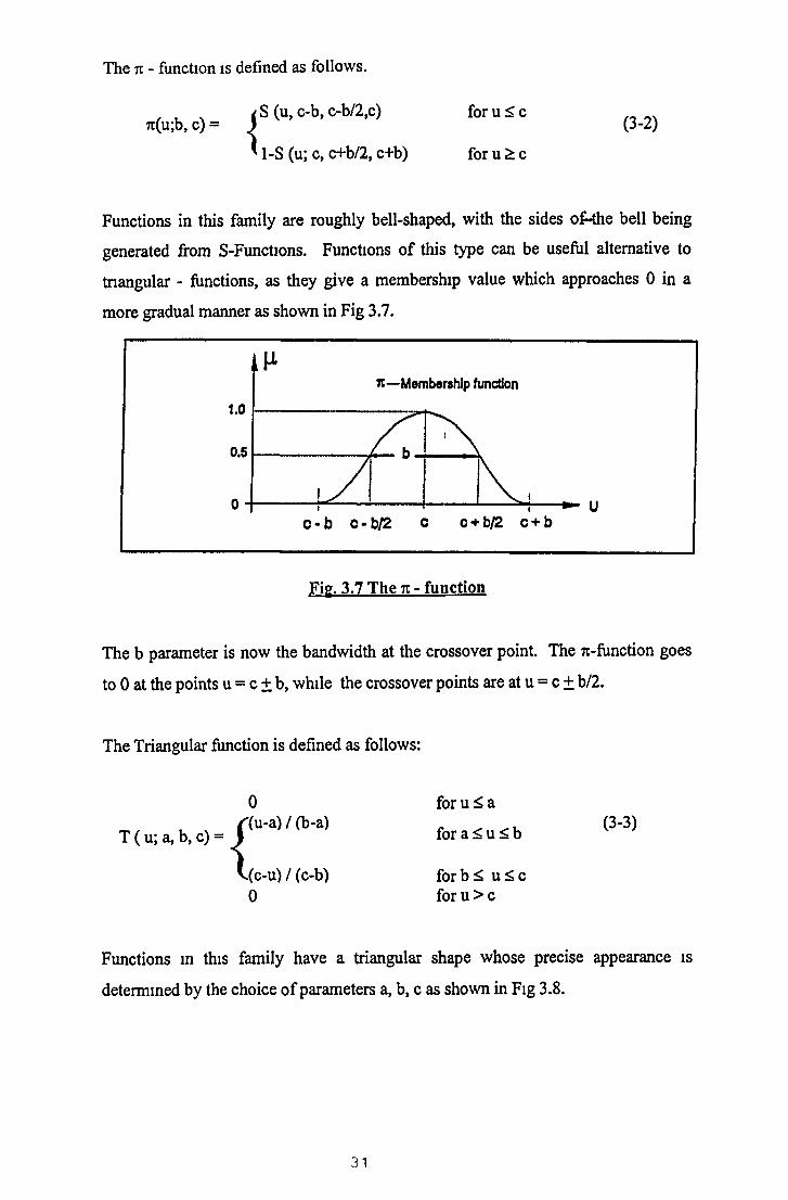
The 7t - function is defined as follows.
j S (u, c-b, c-b/2,c) for u < c7i(u;b, c) = j (3-2)
/ a ^u, C-O,
' 1-S (u; c, c+b/2, c+b) for u £ c
Functions in this family are roughly bell-shaped, with the sides o£-the bell being
generated from S-Functions. Functions o f this type can be useful alternative to
triangular - functions, as they give a membership value which approaches 0 in a
more gradual manner as shown in Fig 3.7.
Fig. 3.7 The n - function
The b parameter is now the bandwidth at the crossover point. The 7i-function goes
to 0 at the points u = c ± b, while the crossover points are at u = c ± b/2.
The Triangular function is defined as follows:
( u; a, b, c) = 1
V i
0 for u ^ a
for a £ u £ b '3'3)
(c-u)/(c-b) forb^ u ^ c0 for u > c
Functions m this family have a triangular shape whose precise appearance is
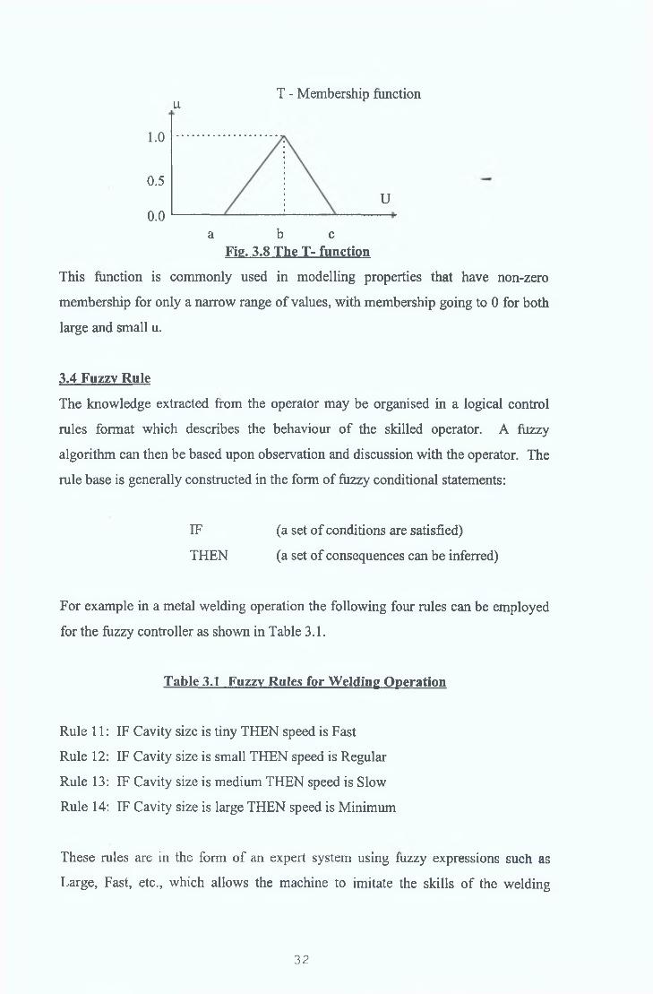
determined by the choice o f parameters a, b, c as shown in Fig 3.8.
31
uT - Membership function
1.0
0.5U
0.0a b c
Fig. 3.8 The T- function
This function is commonly used in modelling properties that have non-zero
membership for only a narrow range o f values, with membership going to 0 for both
large and small u.
3.4 Fuzzy Rule
The knowledge extracted from the operator may be organised in a logical control
rules format which describes the behaviour o f the skilled operator. A fuzzy
algorithm can then be based upon observation and discussion with the operator. The
rule base is generally constructed in the form o f fuzzy conditional statements:
For example in a metal welding operation the following four rules can be employed
for the fuzzy controller as shown in Table 3.1.
Rule 11: IF Cavity size is tiny THEN speed is Fast
Rule 12: IF Cavity size is small THEN speed is Regular
Rule 13: IF Cavity size is medium THEN speed is Slow
Rule 14: IF Cavity size is large THEN speed is Minimum
These rules are in the form o f an expert system using fuzzy expressions such as
Large, Fast, etc., which allows the machine to imitate the skills o f the welding
THEN
IF (a set o f conditions are satisfied)
(a set o f consequences can be inferred)
Table 3.1 Fuzzy Rules for W elding Operation
32

operator The input to the system is the cavity size and the output is the movement
(speed) o f the hand
3.5 Fuzzy Partition of Input/Output Universe
The fuzzy sets defined for input variables in the antecedent o f a fuzzy control rule
form a fuzzy input space with respect to the input universe o f discourse while those
in the consequent o f a fuzzy control rule form a fuzzy output space A fuzzy
partition determines how many fuzzy sets should be defined for each variable along
its universe o f discourse The number o f fuzzy sets m a fuzzy input space imposes
restrictions on the maximum number o f fuzzy control rules that can be constructed
But it should be taken into consideration that the fuzzy partition o f the fuzzy
input/output space is not deterministic and has no umque solution A tnal procedure
is usually needed to find a optimal partition The input universe should be\
partitioned according to the minimum and maximum values allowed to control the
system For example, the input universe o f cavity size might be split into 9 units,
because e g the maximum value allowed to control the process is approximately
three times the diameter of the electrode which is usually 3 mm The output
universe (speed) is split into 15 units according to the range of speed required, which
is between 20 and 35 cm/mm Any value above this range assumed to be infinity
and a zero value is assumed to be the minimum Example partitioning o f input
cavity size and output speed is shown below in Fig 3 9
33

bl Speed M em bership
Fig 3.9 M em bership Functions
3.6 Fuzzv Set Operation.
The use o f fuzzy set operation provides a basis for the systematic manipulation o f
vague and imprecise concepts. The fuzzy set operations are performed through
manipulating the membership functions involved. Some basic fuzzy set operations
are summarised below.
Let A and B be two fuzzy sets based on the same universe with membership
function p.A and jib respectively. Then the following fuzzy set operations can be
defined.
EQUALITY: Two fuzzy sets A and B are equal if they are defined on the same
universe and the membership function is the same for both, that is
|iA (u) = jaB (u) for all u e U (3-4)
Union : The union o f two fuzzy sets A and B with membership functions |x\(u) and (i b ( u ) is the fuzzy set whose membership function n (AUB) (u) is given by
Haub (u) = MAX { nA(u), n„(u)} for all u 8 U (3-5)
Fig 3.10 Union Operation
34
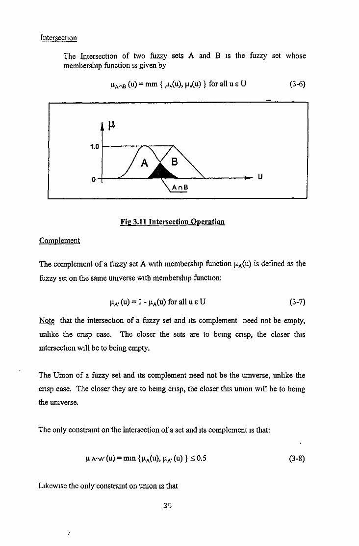
The Intersection o f two fuzzy sets A and B is the fuzzy set whose membership function is given by
1-atiB (u) = mm { nA(u), |iB(u )} for all u s U (3-6)
Intersection
Fig 3.11 Intersection Operation
Complement
The complement o f a fuzzy set A with membership function |aA(u) is defined as the
fuzzy set on the same universe with membership function:
jaA- (u) = 1 - jaA(u) for all u e U (3-7)
Note that the intersection o f a fuzzy set and its complement need not be empty,
unlike the cnsp case. The closer the sets are to being crisp, the closer this
intersection will be to being empty.
The Union o f a fuzzy set and its complement need not be the umverse, unlike the
cnsp case. The closer they are to being cnsp, the closer this union will be to being
the umverse.
The only constraint on the intersection o f a set and its complement is that:
H AnA' (u) = mm {P-A(u), \iA. ( u )} ^ 0.5 (3-8)
Likewise the only constraint on union is that
35
)

r
JJ-aua' (u) = max {nA(u), nA.(u )} £ 0.5 (3-9)
Depending on the membership function, various results can be achieved for fuzzy
sets which have no corresponding feature for crisp sets.
Fig 3.12 Fuzzy Complement
Normalisation
This process simply involves re-scalmg the membership function so that its
maximum value is 1, that is
janorm(A)(u) = jj.a (u )/ MAX(jaA (u )) u s U (3-10)
Concentration
A fuzzy set A can be ‘concentrated’ by modifying its membership function |iA(u) so
as to accentuate the membership o f the higher membership elements. This is done
by squaring the normalised membership function, that is
(j.coN(A) (u) = (Ha(u))2 for all u e U (3-11)
Fig 3.13 Concentration of a Fuzzy Set
36

Dilation
A fuzzy set A can be ‘dilated’ by modifying its membership function }iA(u) to
increase the importance o f lower membership elements This is done by taking the
square root o f the normalised membership function, that is
Hdil(A)(u) = (h a (u)) 0 5 for all u e U (3-12)
Fig 3.14 Dilation of a Fuzzy Set
Intensification
This operation moves the normalised fuzzy set closer to being crisp, by enhancing
the membership value o f those elements whose membership was above 0.5 and
diminishing that o f those elements with membership below 0.5. This corresponds to
a contrast enhancement type o f operation, as denoted by
umt ru)= ( 2(^a(u)2 , for 0 ^ fxA(u) 0.5 (3 . 13)^ (A)( ) 1-2 (l-u.fuY) for 0 .5 < u . r u ^ 1
Fig 3.15 intensification of a fuzzy set
37

Algebnc Product
The algebnc produce o f two fuzzy sets A and B with membership function ^ a ( u )
and |ab( u ) i s the fuzzy set whose membership function |i A.B(U) is given —
H a.b(u) = ( M u) # M u)} for all u s U (3-14)
Bounded Sum
The bounded sum of two fuzzy sets A and B with membership functions (I A(u) and
fO, B(u) is the fuzzy set whose membership function |Ha ©b ( U ) is given
Ha ©b (u) = min { 1, |xA(u) + |iB( u ) } for all u s U (3-15)
Where ‘+ ’ is the anthmetic sum operator
Bounded Product
The bounded product o f two fuzzy sets A and B with membership function |iA(u)
and |aB(u) is the fuzzy set whose membership function (J.A o b (u ) i s given
M,ao b(u ) = m a x { H a ( u ) + | ^ b ( u ) - 1 } for all u b U (3-16)
where *+’ is the anthmetic sum operator
Drastic Product
The drastic product o f two fuzzy sets A and B with membership functions |iiA(u) and
HB(u) i s the fuzzy set whose membership function M-a®b(U) is given
T |iA(u) for |iB(u) = 1
M’b(u) for ^ A(u) = 1 (3-17)
^ a®b(U) =
L 0 for |iA(u ) , |iB(u) < 1
38

Cartesian Product
I f A„ A2, A3 An are fuzzy sets m U„ U2j_U3 Un respectively, the Cartesian
product o f A„ A2, A3 An is a fuzzy set F in the product space U, x U2 x U3 x
Un with the membership function __
|aF (u, i^) = mm { |aA1(u,) u ^ u j } (mm) (3-18)Or
MP (U, un) = ^ A1(u1) ^„(Un) Product (3-19)
where F = A, x A2 x A3 x An
Sup-Star Composition
IF A and B are fuzzy relation in U x V and V x W respectively, the composition o f
A and B is a fuzzy relation known as AoB, where AoB is denoted by
AoB = {[(u,w), SUP ( h p ( u ,v ) * |iB(v,w))], usU, veV, weW (3-20)
Where * is the sup-star compositional operator and could be any compositional
operator m the class o f triangular norms, namely, minimum, algebnc product
bounded product, or drastic product
Example - The Max -Mm based compositional operator plays an important role in
establishing the fuzzy relation equation for a fuzzy knowledge base In fact, the
composition operation is the net effect o f applying one relation after another In
most applications, the composition can be defined by max-min functions which deal
with matnx product operations Let A and B be defined as follows
To 1 0 4] Co 2 0 6 0 8]
A = B =
L0 7 0 9 j L0 7 0 4 0 5j
Then the relation, R can be obtained using max-min compositional operations
TO 1 0 4 l f 0 2 0 6 0 8l
R = AoB = o
L0 7 0 9j 0 7 0 3 0 5j
39

fRii R 1 2 R n l
LR21 R22 R23J
where
R 11 = Max (min (0.1, 0.2), min (0.4, 0.7)}
= Max {0.1, 0.4}
= 0.4
R 12 = Max {min (0.1, 0.6), min (0.4, 0.3)}
= Max { 0.1, 0.3 }
= 0.3
R 13 = Max {min (0.1, 0.8), min (0.4, 0.5)}
= Max { 0.1, 0.4 }
= 0.4
R 21 = Max {min (0.7,0.2), min (0.9, 0.7)}
= Max { 0.2, 0.7 }
= 0.7
R 22 = Max {min (0.7, 0.6), min (0.9, 0.3)}
= Max { 0.6, 0.3 }
= 0.6
R23 = Max {min (0.71, 0.82), min (0.94, 0.57)}
= Max { 0.7 , 0.5 }
= 0.7
3.7 Fuzzy Relation.
The fuzzy relation is the relationship between the object in the condition section
(known as ‘input’) and the object in the consequence section (known as ‘output’).
For example, the object in the condition section (or input) in rule base 1 (see table
40

3.1) is referred to “cavity size” while the object in the consequence section (or
output) in rule base 1 is referred to “speed”.
Let the object in the condition section o f the jth rule base is denoted by INPUT* and
the object in the consequence section o f the jth rule be denoted by OUTPUTJ. Thus
from Table 3.1 the INPUT1 and OUTPUT’ can be outlined as follows:
Table 3.2: INPUT and OUTPUT Term s
RULEBASE INPUTJ OUTPUT1
1 Cavity Size Speed
For the ith rule in jth rule base Rji, the fuzzy relation between the input and output
can be denoted by
Rji = [INPUTj] j * [O U TPU T^ (3-21)
where * denotes the cartesian product for fuzzy relations.
The membership function (iRji, for the fuzzy relationship is given by:
= MIN { n[INPUTj]i, n[OUTPUTj] i } 3-22)
where
|a[INPUTJ]j----------- the membership in the descrete universe
corresponding to the ith fuzzy input term in the
condition section o f the jth rule base.
(j.[OUTPUTJ] , the membership in the descrete universe
corresponding to the ith fuzzy output term in
the consequence section o f the jth rule base.
41

By combining all the rules in the jth rule base using the fuzzy operator “OR”, the
membership function for the relationship between the INPUT and OUTPUT o f the
jth rule base is given by
M-fu = MAX { laRjl, (J.Rj2, (J.Rj3 ^Rjn} ~ (3-23)
Thus, the fuzzy relations between the INPUT and OUTPUT for all the rule bases can
be established by using e.g. (3-5) and e.g (3-6).
The defuzzified output which gives the average speed value can be obtained from
the following formula:
Average value = Z speed value x |i(s) / £ |i(s) (3-24)
3.8 Fuzzy Set Shapes.
Different applications o f the fuzzy control technique use specific shapes o f the fuzzy
sets which are dependent on the system behaviour identified by the knowledge
engineer. So far there is no standard method o f choosing the proper shape o f the
fuzzy set o f the control variables. The scale suggested for the fuzzy variables o f the
control systems are termed “fuzzyimetric arcs”. Since the main interest in this
project is the application o f the fuzzy control to manufacturing processes, the use o f
fuzzimetric arcs and the application o f fuzzy control theory has been selected to
demonstrate the more efficient metal cutting speed for different type o f metal
hardness.
The first step in establishing the fuzzy control system is the selection o f the proper
shape o f fuzzy sets o f the control variables based upon observation o f the system
behaviour. The fuzzy set shape is an influencing factor on the performance o f the
controller and may be altered to obtain the most suitable form o f the fuzzy variables.
Since a fuzzy control algorithm is one means o f imitating humans performance, the
shape o f the fuzzy sets o f the control variables should be logical and acceptable to
individuals. For example, as shown in Fig 3.16 for three fuzzy variables specified as
very soft, soft and medium soft in a universe o f discourse U, the output universe o f
42

discourse in metal cutting process would be all the possible values o f the cutting
speed
very soft soft medium soft very soft soft medium soft
Fig 3.16 Difference between unacceptable (a
and acceptable (b) fuzzy set shape.
An overlap between medium soft and soft or an overlap between soft and very soft is
logical and acceptable However an overlap between medium soft and very soft is
not acceptable to individuals, especially when dealing with numeric application o f
the type considered in manufacturing process
The fuzzy system vanables include input variables and output variables The input
variables, known as process state vanables, are measured from the controlled
process, while the output vanables, known as process control vanables, are inferred
from FLC (fuzzy logic control) The proper choice o f input vanables and output
vanables is essential to the successful design o f a fuzzy control system The
definition o f the fuzzy set for each system vanable has a substantial effect on the
performance o f an FLC
Depending on the complexity o f the fuzzy system the number o f input and output
vanables vanes For a system with n input vanables and m output vanables, it is
often called as n-mput-m-output system In the case that n=l and m =l, the fuzzy
system is said smgle-input-single-output (SISO) In the case that n > 2 and m = 1,
the fuzzy system is said multi-mput-single-output (MISO) In the case that n > 2
and m > 2, the fuzzy system is said multi-input-multi-output (MIMO)
The fuzzy sets for each variable are defined in linguistic terms such as VS (Very
Soft), SO (Soft), MS (Medium Soft), ME (Medium), MH (Medium Hard), HA
43

(Hard) and VH (Very Hard) etc The number o f the fuzzy sets defined for each
variable determines the granularity o f the control obtainable with an FLC To assist
the fuzzy reasomng, a fuzzy membership function has to be defined for each fuzzy
set m the corresponding universe o f discourse There are two ways to define the
membership for a fuzzy set numerical and functional as mentioned m section 3 3
A numerical definition expresses the degree o f membership function o f a fuzzy set
as a vector o f numbers whose dimension depends on the level o f discretisation m the
, universe o f discourse
A functional definition denotes the membership function o f a fuzzy set in a
functional form, such as S-Function, N-Function, triangular type, trapezoid type,
exponential type etc Either a numerical definition or a functional definition may be
used to assign the grades o f membership to a fuzzy set
Although the choice o f the number, range and shape o f membership functions for a
variable is based on subjective catena, they can still be determined for most fuzzy
logic based control system by using the following rules
a Aim for a symmetncal geometncal distnbution o f membership functions in
the defined universe o f discourse
b Odd number o f fuzzy sets for each vanable
c Overlap adjacent fuzzy sets to ensure more than one rule may be applied
CHAPTER 4 MACHINABILITY ASSESSMENT OF A MATERIAL
4.1 Introduction.
This chapter presents an overall description about machinabihty assessment and theIs
factors affecting machinabihty A brief discussion about the different cutting tool
materials is presented The different parameters usually investigated for a
machinabihty test are also dealt with
4.2 Machinability.
It has been suggested that the word “machinabihty” was first used in the 1920’s and
referred specifically to the speed/tool life relation [79] Now, machinabihty is
defined in various ways The term machinabihty is used to refer to the ease with
which a workpiece material is machined under a given set o f cutting conditions A
prior knowledge o f a workpiece material is important to the production engineer so
that its processing can be planned efficiently “Good machinabihty” can mean that
less power is required or a higher tool life is achievable or a better surface finish can
be obtained to machine that particular material Moreover, ease o f chip disposal,
cutting temperature, operator safety, etc are other criteria o f machinabihty as well
Machinabihty o f a one material may be better with respect to surface finish under a
set o f cutting conditions while machinabihty o f another material may be better with
respect to tool life under a different set o f cutting conditions
Boulger [80] has defined machinabihty as the removal o f chips with satisfactory tool
life and surface finish Boston [81] has defined machinabihty as the response o f a
metal to machining which gives long tool life under otherwise equal conditions
when compared with other materials, provides good surface finish, produces well
broken chips, gives uniform dimensional accuracy o f successive parts, produces
each part at the lowest overall cost, and requires lower power consumption in
removing a given quantity o f chips
45

e
According to Eamst [82], the term machinabihty means a complex physical property
o f a metal which involves true machmability, fimshabihty or ease o f obtaining a
good surface finish and abrasion undergone by the tool during cutting
Reen [83] has pointed out that for accurate rating o f machmability, three factors
namely, tool life, surface finish, and power consumed during cutting must be
considered Trent [84] has outlined that tool life, cutting force, chip shape, surface
finish/ integrity are all important parameters for machmability assessment o f a
material According to Sandvik [85] machmability o f a material is the ability o f the
work material to be machined
In general machmability o f a material can be considered as a combination o f small
cutting force, high metal removal rate, better surface fimsh/integnty, longer tool life,
well broken chips, and uniform dimensional accuracy The different factors
influencing machmability o f a material are (l) machining operations (11) workpiece
properties, (in) cutting conditions, ( i v ) tool properties, and (v) machine tool - tool-
workpiece dynamics
The machining operation may be a continuous cutting operation l e turning or an
intermittent cutting operation i e milling The cutting conditions which influence
the machmability parameters are cutting speed, depth of cut, feed rate, and cutting
fluid As the cutting speed increases, tool life decreases This is true for feed as
well Moreover, as the feed rate increases, the power consumption during cutting
also increases The higher the depth o f cut, the greater the power consumption
The tool material and its geometry have an influence on the machmability o f a
matenal The requirements o f a good cutting tool are its high hardness and
toughness, good wear resistance, mechanical and thermal shock resistance and the
ability to maintain these properties at the very high temperatures encountered during
metal cutting operations Rake angle o f a cutting tool has an effect on the cutting
force As the rake angle becomes positive, the cutting force decreases [86]
46

The workpiece properties also have a pronounced affect on machmabihty which are
its micro-structure, chemical composition, and physical properties A small change
m the microstructure o f a material can greatly affect its machmabihty [87] The
chemical composition o f a material also influence its machmabihty The presence o f
sulphur, lead, and phosphorous improves machmabihty o f a material while
chromium, vanadium, mckel and molybdenum retard machmabihty The presence
o f hard abrasive carbides in the microstructure can have a detrimental effect on
machmabihty [88] The physical properties o f a material affecting machmabilty are
its hardness and work hardening properties [89]
Tool material and geometry must be chosen carefully in relation to the workpiece
material to be machined and the kinematics and stability of the machine tool to be
employed The mam cutting tool materials m use are (i) high speed steel, (11) cast
alloys, (111) cemented tungsten carbides, ( i v ) coated cemented carbides, (v) T1C-T1N
based cements, (vi) ceramics, (vu) polyerystalhne diamond and cubic boron nitride,
and (vm) single crystal diamond
Tungsten based cemented carbide is the oldest among the hard cutting tool materials
in use The present tungsten carbides for cutting applications are classified into K,
M and P codes The K group is used for cutting materials such as grey cast irons,
non ferrous alloys, and non metals The M group is used for cutting materials with
long to medium chips such as steel castings, austemfic steels and ductile cast iron
The P group is for cutting materials with long chips such as carbon steel, alloy steels
and femtic steels Coated carbides have the advantage of wear resistance o f
ceramics and the strength o f cemented carbides The coating materials are TiC, TiN,
and A1203 and the coating layers may be single, or multiple with coating thickness
varying from 3 - 1 0 |am The mam factors affecting the cutting performance o f
coated tools are the kind o f coatings, the thickness o f the coating, the coating method
and the substrate
A range o f machmabihty tests have been developed, often to assess specific cutting
conditions, whilst others are used for more general assessment In general a
machmabihty test assesses the speeds and feeds which are varied by trial and error
r \
47

and with specified constrains [90] Nevertheless, the three mam parameters o f
machinability assessment are (1) cutting force, (11) tool life, and (111) surface finish
Figure 4 1 shows different machinability parameters in the form o f an mput/output
model o f a turning operation A brief discussion o f these parameters follows
4.2.1 Cutting Force.
The metal cutting process is a result o f relative movement between the cutting tool
and the workpiece material which has to be machined The relative movements
between the cutting edge and the work piece material results m an amount o f metal
corresponding to the depth o f cut being separated from the workpiece material m the
form o f chips whilst the feed movement brings new material m front o f the cutting
edge after a particular cut has been finished
An understanding o f the forces and velocities which occur during the various cutting
process is the essential basis for determining the size and material o f the load
transmitting elements together with the required driving power The machining
processes can be classified into (l) Orthogonal cutting processes and (11) oblique
cutting processes In orthogonal cutting, the cutting edge o f the tool is arranged to
be perpendicular to the direction o f relative work tool motion as shown in Fig 4.2(a)
and involves two forces The oblique cutting, as shown in Fig 4 2(b), on the other
hand, involves a three-force situation where the cutting edge o f the tool is inclined at
an angle to the cutting velocity Since orthogonal cutting represents a two-
dimensional force, it is widely used in theoretical and experimental work
The wedge-shaped cutting tool basically consists o f two surfaces intersecting to
form the cutting edge as shown in Fig 4 3
The surface along which the chip flows is known as rake face, or more simply as the
face, and that surface ground back to clear the new or machined workpiece surface is
known as the flank Thus during cutting a wedge -shaped “clearance crevice” exists
between the tool flank and the new workpiece surface
48

INPUT
M a c h i n i n g v a r i a b l e s S p e e d V ( m / m i n ) F e e d £ ( m m / r e v ) D e p t h o f c u t d ( m m )
W o rk p ie c eM a t e r i a l t y p e & g r a d e H a r d n e s s , S p . h e a t , t e n s i l e s t r e n g t h e t c .
C u t t i n g t o o lM a t e r i a l ( H S S , C a r b id e , C e r a m i c )
G e o m e t r y ( N o s e r a d iu s , r a k e & r e l i e f a n g l e , e t c .
MACHINING PROCESS
T u r n i n g , D r i l l i n g , M i l l i n g , e t c .
OUTPUTC u t t i n g t o r c eA x i a l F„R a d ia l FyT a n g e n t i a l F,
S u r f a c e r o u g h n e s s R , ( C . L . A )
P o w e rP = f ( F „ V )
■T o o l l i f e (T ) F la n k w e a r V B B C r a te r d e p t h K T
T = f ( V , f , d , V B B)
R , = f ( V , f , d , N R )
Figure4 .1 Various machinability parameters in a machining process.

Fig. 4.2 Orthogonal (ai and oblique cutting Ori
Working norma!
c lea ran ce
Fig. 4.3 Cutting Edge and Tool Flank
50
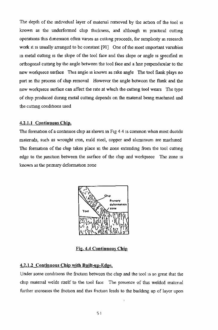
The depth o f the individual layer o f material removed by the action o f the tool is
known as the underformed chip thickness, and although m practical cutting
operations this dimension often vanes as cutting proceeds, for simplicity in research
work it is usually arranged to be constant [91] One o f the most important vanables
in metal cutting is the slope o f the tool face and this slope or angle is specified m
orthogonal cutting by the angle between the tool face and a line perpendicular to the
new workpiece surface This angle is known as rake angle The tool flank plays no
part in the process o f chip removal However the angle between the flank and the
new workpiece surface can affect the rate at which the cutting tool wears The type
o f chip produced dunng metal cutting depends on the matenal being machined and
the cutting conditions used
4.2.1.1 Continuous Chip.
The formation o f a continuos chip as shown in Fig 4 4 is common when most ductile
matenals, such as wrought iron, mild steel, copper and aluminium are machined
The formation of the chip takes place in the zone extending from the tool cutting
edge to the junction between the surface o f the chip and workpiece The zone is
known as the pnmary deformation zone
4.2.1.2 Continuous Chip with Built-up-Edffe.
Under some conditions the faction between the chip and the tool is so great that the
chip matenal welds itself to the tool face The presence of this welded matenal
further increases the friction and this friction leads to the building up of layer upon
Fig. 4.4 Continuous Chip
51

layer o f chip material The resulting pile o f welded chip material is referred to as a
built-up edge as shown m Fig 4 5 Often the built-up edge continues to grow and
then breaks down when it becomes unstable, the broken pieces being earned away
by the underside o f the chip and the new workpiece surface Fig 4 6 shows the
rough work piece surface obtained under these conditions This built-up edge
formation in metal cutting is one o f the most important factors affecting surface
finish and can have a considerable influence on cutting-tool wear
4.2.1.3 Discontinuous Chip.
Dunng the formation o f a chip the material undergoes severe strain and if the
workpiece material is brittle, fracture will occur in the primary deformation zone
when the chip is partly formed Under these conditions the chip is segmented as
shown m Fig 4 6 and this is known as discontinuous-chip Discontinuous chips are
always produced when machining such matenal as cast iron or cast brass but may
also be produced when machining ductile materials at very low speeds and high
feeds
4.2.2 Tool Life.
Tool life is defined as the cutting time required to reach a tool-life criterion The
most significant factor affecting tool life when workpiece matenal, tool matenal and
tool shape are chosen for a particular machining operation is the cutting speed In
metal cutting operations the tool life is one o f the most important economic
considerations In roughing operations, the vanous tool angles, cutting speed and
feed rates are usually chosen to give an economical tool life Any tool or work-
matenal improvement that increases tool life is beneficial Cutting tools are m metal
to metal contact with the chip and workpiece under conditions o f very high stress at
high temperature The existence o f extreme stress and temperature gradients near
the surface o f the tool further aggravates the situation
5 2
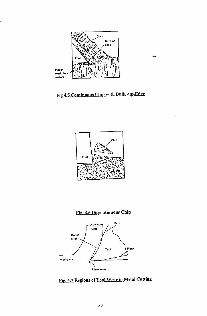
Fig 4.5 C o n t i n u o u s Chip w ith Built-UP-Edgg
Fig. 4.6 Discontinuous Chip
F lan k w ear
Fig. 4.7 Regions of Tool Wear in Metal Cutting
53

The term tool wear refers to the degradation of the cutting and/or clearance surface
o f the tool, fracture and a reduction of the tool mechanical properties due to high
temperature [92] Tool wear is a product o f a combination o f four load-factors
which continually attempt to change the geometry of the cutting edge [93] These
four factors are mechanical, thermal, chemical and abrasive which result in five
basic wear mechanisms such as (1) adhesive wear, (11) abrasive wear (111) diffusion
wear, ( i v ) fatigue wear and (v) oxidation wear Acting m isolation or in
combination, these mechanisms cause two distinct wear modes [92] The first type
is known as irregular wear which includes cracking, breakage, chipping and plastic
deformation o f the insert The second type is defined as regular wear consists o f
flank wear on the nose and the crater wear across the rake face o f the tool insert as
shown in Fig 4 7
Flank wear is generally the normal type o f tool wear and is caused by friction
between the newly machined workpiece surface and the contact area on the tool
flank
This results m a loss o f relief angle on the clearance face of the tool The width o f
the wear land gives an indication o f the amount of wear and can be readily measured
by means o f a toolmaker’s microscope
Flank wear is responsible for increasing the cutting force and the interfacial
temperature Crater wear, on the other hand, is usually observed when machining
steel and other high melting point metals at a relatively high cutting speeds The
crater formed on the tool face conforms to the shape o f the chip underside and is
restricted to the chip-tool contact area The crater is formed some distance away
from the cutting edge m the region where the tool is hottest In addition, the region
adjacent to the cutting edge where sticking friction or a built-up edge occurs is
subjected to relatively slight wear Under high temperature conditions high speedt
steel tools will wear very rapidly because o f thermal softening o f the tool material
With carbide-tool materials, although they retain their hardness at high temperature,
solid-state diffusion can cause rapid wear
54

In adhesion wear [94], the wear is caused by the formation o f welded joints and the
subsequent destruction o f these joints between the chip and tool materials In metal
cutting, junctions between the chip and tool materials are formed as part o f the
friction mechanism and when these junctions are fractured, small fragments o f tool
matenal can be tom out and earned away on the underside o f the chip or on the new
workpiece surface
Abrasive wear occurs when hard particles on the underside o f the chip pass over the
tool face and remove tool matenal by mechanical action These hard particles may
be highly stram-hardened fragments o f an unstable built-up edge, fragments o f the
hard tool matenal removed by adhesion wear or hard constituents in the workpiece
matenal Thus the abrasion process depends on the hardness, the elastic properties
and the geometry o f the two mating surface Usually, the larger the amount o f
elastic deformation a surface can sustain, the greater will be its resistance to abrasive
wear [95]
In diffusion wear, solid-state diffusion plays an important role when surface
temperature becomes very high and surface velocities are low Bowden and Tabor
[96] suggested that some diffusion must occur in the adhesion of contacting
aspenties In metal cutting operation, where intimate contact between the work and
tool matenals occurs and high temperatures exist, diffusion can take place where
atoms move from the tool matenal to the work matenal This leads to the
weakening o f the surface structure o f the tool
A tool life cntenon is defined as a predetermined threshold value o f a tool wear
measure which indicates that a tool is to be rejected after the threshold value is
reached In practical machining operation, the wear of the face and flank o f the
cutting tool is not uniform along the active cutting edge Therefore it is necessary to
specify the locations and degree o f the wear when deciding on the amount o f wear
permissible before rejecting the tool
55

4.2.3 Surface Roughness.
To produce a desired shape and size by removing the excess material from the
workpiece in the form of chips, the workpiece has to undergo machining operations.
The workpiece is subjected to intense mechanical stress and localised heating by
tools with one or more shaped cutting edge. In turning operation each cutting edge
leaves its own mark on the machined surface. Roughness o f a surface refers to a
property o f a machined surface. Surface roughness consists o f relatively closed
spaced or fine surface irregularities, mainly in the form of feed mark left by the
cutting tool on the machined surface. It is measured by the heights o f the
irregularities with respect to a reference line. The surface texture o f a machined
surface consists o f primary texture (roughness) and secondary texture. The primary
texture can be measured by various indices such as average arithmetic roughness
height Ra, smoothing depth Rp, maximum roughness Rt and root mean-square RMS
height [97], With the exception of RMS, these various indices (Ra, Rp, Rt) are
common in use. The index most commonly used is the arithmetic roughness height
The secondary texture, also known as ‘waviness’, is that part o f the surface texture
which underlies the roughness. All types o f machine vibrations and inaccuracies in
the machine tool movement may contribute to secondary texture. Fig 4.8 shows the
various components and parameters of a machined surface. According to the British
system the average arithmetic roughness Ra is also known as centre line average
CLA and in America Ra is known as AA which is arithmetic average. Ra is quoted
in microns representing a mean value of roughness. The CLA or AA roughness Ra
is obtained by measuring the mean deviations of the peaks from the centre line o f a
trace, the centre line being established as the line above and below which there is a
equal area between the centre line and the surface trace. The theoretical relationship
between the surface roughness value and the feed / is given by the following
equation [98]. Ra = 0.0321 f 2 / r E
where r E is the comer radius of the cutting tool and / (mm/rev) is the feed rate.
56

Rp (smoothening depth) is the distance between the highest point and the mean line
and usually results from the conditioning o f the cutting tool The maximum peak to
valley height within the tracing stroke o f a surface profile is known as Rt The RMS
is average geometric roughness and was an American standard Its numerical value
is some 11% higher than that o f R g .
A *« Roughness spacing R ,* Average arithm etic roughnessAw= Waviness (Secondary (exture) R * Smoothening depthR, - Roughness (Primary texture) RMS - Root-Mean-SquarcW + R, ■ Waviness + Roughness
Fig. 4.8 Various Components and Parameters of a machined surface.
57

4.3 Effect of Machining Parameters on Surface Finish.
Surface finish can be influenced by several machining parameters such as cutting
conditions, cutting tool geometry, workpiece geometry, machine tool rigidity,
workpiece material and tool matenal Each o f these parameters are discussed
briefly
4.3.1 Cutting Conditions.
At low cutting speed, the cutting forces are high and the tendency of forming built-
up edge is stronger But at a relatively small cutting speed, the built-up edge does
not form because o f the cutting temperature being too low As the speed is
increased, conditions become more and more favourable for built-up edge formation
But when the cutting speed is increased further, the built-up edge size starts
decreasing because o f the increased tool temperature Thus at a sufficiently high
speed, the built-up edge disappears altogether and surface finish becomes insensitive
to cutting speed Feed and depth of cut have a large effect on surface finish Feed
has the much larger effect o f the two Increase in depth o f cut tends to increase
waviness height
4.3.2 Cutting Tool Geometry.
The larger the rake angle, the smaller are the cutting forces and due to that
deflections and waviness heights are also small Rubbing by the tool imprints the
uneven-wear profile o f the cutting tool on the machined surface Adequate relief
angles help the escape o f the built-up edge fragments and avoid their getting
embedded on the machined surface When major and minor (l e the side and end-
cutting) edges are joined by a nose o f large radius it reduces the sharpness o f the tool
and lessens the sawtooth effect o f the feed marks and improves surface finish
However, an excessive nose radius is harmful because it can cause vibration and
chatter The side and end cutting edges have little effect on surface roughness
When the side-cutting edge angle is increased, it reduces true feed and improves
chip flow and surface finish Larger side-cutting edge angles may prove harmful to
surface finish by causing chatter Increase in the end-cuttmg edge angle increases
height o f feed marks and ends up with a worse finish
58

4.3.3 W orkpiece Geometry.
Workpieces have low stiffness against both static and dynamic forces when they are
long and slender. Due to that reason waviness effects are more pronounced. But if
the workpiece has a large cross-section or is rigidly clamped on the machine, the
waviness height is small.
4.3.4 M achine Tool Rigidity.
In a machining operation, high feed or large work-tool engagement may be limited
because o f “chatter”. Chatter is the condition where unwanted vibrational motion
exists between the workpiece and the tool and as a result of that it produces a pattern
o f irregularities on the workpiece surface. It also causes work-tool displacement.
The desirable conditions o f a machine tool are that it should have sufficient drive
power for all the cutting and feed motions so that it can maintain the required cutting
speed and feed without stalling, adequate stiffness against static deflections, rigidity
against vibration, proper foundation to minimise vibration and finally a means to
rigidly support the workpiece and the cutting tool relative to each other.
4.3.5 W orkpiece M aterial.
Chemical composition, hardness o f materials, microstructure and metallurgical
consistency affect surface finish. Steels having 0.1% or less carbon produce built-up
edge during chip formation and thus spoil the surface. On the other hand when a
free machining element such as sulphur, selenium or lead is added it helps to reduce
built-up edge. Cutting tools dig into a material with very low hardness and ductility
and can not produce the good surface finish. High hardness and strength and low
ductility result in good surface finish. Workpiece strain hardenability can be
improved by cold working and thus obtaining a good surface finish.
Fine grain size and high hardness o f microconstituents are favourable for getting a
good finish. Cutting action can turn the softer constituents into fragments and the
surface may become pitted. Uniformity o f finish of a machined surface can be
determined by the metallurgical consistency of the workpiece. Usually a rod or a
casting is comparatively softer at its core than at its surface. As the machining
59

operation continues, the surface roughness increases as the centre o f the bar is
approached
4.3.6 Tool Material.
Different tool materials have different degrees o f hot hardness, toughness and
frictional behaviour A tool can be used at high speed if its hot hardness is high and
thus built-up edge practically disappears High speed can be applied to cemented
carbide and oxides in this respect compared with carbon steels and high speed steel
(HSS) Larger rake and relief angles can be given to a tool made o f a tough material
without endangering the cutting edge In this regard HSS is a better tool material
than cemented carbide and oxides Usually if the friction between the tool and the
work-matenal is smaller then it produces better surface finish on the workpiece
Carbides and oxides are better m this respect when compared with high speed steel
(HSS)
4.3.7 Cutting Fluid.
Cutting fluid acts as a coolant during machining It reduces tool wear and helps to
keep the cutting edge intact, and thus has an indirect effect on tool life It also
reduces the friction between the sliding surface o f the tool, work and chip by acting
as a lubricant All the points mentioned above collectively tend to improve the
surface finish o f the machined surface
60

CHAPTER 5 DEVELOPMENT OF FUZZY MODELS
5.1 Introduction.
Constructing fuzzy control rules is one of the most important steps in designing a
fuzzy control model Fuzzy control rules provide a convenient way to create fuzzy
relations between input and output variables Most fuzzy logic control (FLC)
designs are based on expert experience and control engineering knowledge which
are expressed in IF-THEN rules In many control system, the mput-output relations
are not known with sufficient precision to make it possible to employ classical
control theory for modelling and simulation In that situation modelling the
operators’ control actions is earned out by observing the actions o f human
controllers in terms o f the mput-output operating data
To model a fuzzy logic system we need the following steps
Step -1 .
Determine the important known input and unknown output parameters
Step - 2.
Establish a number o f rules to express the relation between known input
parameters and unknown output parameters
Step - 3.
Divide the range for each input and output parameter into a number o f fuzzy
sets o f tnangular or other suitable overlapping shapes
Step - 4.
Establish membership functions for these fuzzy sets for each parameter
Complete the table using the descretized universe for each parameter
showing (i values for each fuzzy set
Step - 5.
Construct the table o f relationship for each rule used in step-2
61

Step - 6.
Demonstrate that for known input and for the corresponding relations, the
output can be calculated
Step - 7.
Establish the composite relation table for any output by combining all the
rule bases and fuzzy algorithm
r
5.2 Data Used.
The materials used for this work are,
1) Free Machining Carbon Wrought Steel
2) Medium Carbon Leaded Steel
The first material (Free Machimng Carbon Steel) is divided into four groups
depending on the hardness (BHN) These groups are as follows
1 From 225 -275
2 From 275 -325
3 From 325 -375
4 From 375-425
The second material (Medium Carbon Leaded) is divided into six groups depending
on the hardness (BHN) The groups are as follows
1 From 125 - 175
2 From 175 -225
3 From 225 -275
4 From 275 -325
5 From 325 - 375
6 From 375 -425
Data for three different depths o f cut (1mm, 4mm„ 8mm) and four different types o f
tools were used for the calculations The four different types o f tools are as follows
62
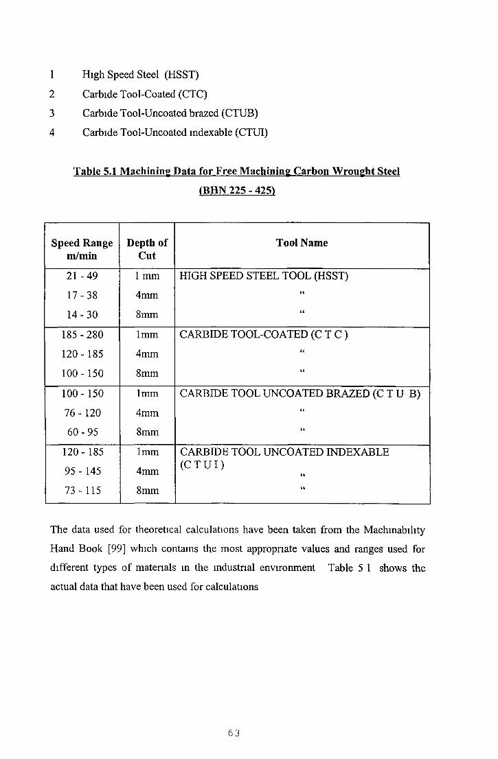
1 High Speed Steel (HSST)
2 Carbide Tool-Coated (CTC)
3 Carbide Tool-Uncoated brazed (CTUB)
4 Carbide Tool-Uncoated indexable (CTUI)
Table 5.1 Machining Data for Free Machining Carbon Wrought Steel
(BHN 225 - 425^
Speed Range m/min
Depth of Cut
Tool Name
2 1 -4 9
1 7 -3 8
1 4 -3 0
1 mm
4mm
8mm
HIGH SPEED STEEL TOOL (HSST)«
185 -280
120-185
100-150
1mm
4mm
8mm
CARBIDE TOOL-COATED ( C T C )<<
100-150
76 -120
6 0 -9 5
1mm
4mm
8mm
CARBIDE TOOL UNCOATED BRAZED ( C T U B )<4
«
120-185
95 - 145
73 - 115
1mm
4mm
8mm
CARBIDE TOOL UNCOATED INDEXABLE ( C T U I )
a
The data used for theoretical calculations have been taken from the Machmability
Hand Book [99] which contains the most appropriate values and ranges used for
different types o f materials in the industrial environment Table 5 1 shows the
actual data that have been used for calculations
63

5.3 Membership Functions for Metal Cutting.
The triangular membership function is employed to describe the fuzzy sets. In
model one the fuzzy sets overlapped at the 50% level In model two the fuzzy sets
overlapped at the 33% level. The fuzzy sets for the input fuzzy variable
HARDNESS are listed below and shown m Fig 5 1 and membership functions for
the fuzzy sets are shown m Fig 5.2
Fuzzy Sets
Fig 5.1. Input Fuzzy Variables
Hardness
Fig 5.2. Hardness Membership (model-1^
The fuzzy sets for the output fuzzy variable cutting SPEED are listed below in F ig ,
5 3 and membership functions for the fuzzy sets are shown in Fig 5 4

Fuzzy Sets
VSLOW - VERY SLOWSPEED
SLOW - SLOW SPEED
MSLOW - MEDIUM SLOW SPEED
MDHI - MEDIUM HIGH SPEED
HI - HIGH SPEED
VHIGH - VERY HIGH SPEED
Fig 5.3 O utpu t Fuzzy Variables
Fig 5.4 C utting Speed M em bership (Model-1)
The universe o f input (Hardness) and output (Cutting Speed) has been partitioned
according to the assigned range o f the fuzzy variables and different membership
values are assigned to each element o f the discrete universe. From Fig 5.2 and 5.4
the descretized universe o f fuzzy variables (Hardness and Cutting Speed) has been
derived as shown in Table 5.2 and Table 5.3 respectively.
Table 5.2 Descretized Universe of H ardness
fuzzy
terms
0 I 2 3 4 5 6 7 8 9 10 11 12 13 14 15 16 17 18 19 20
V S 1 •75 '50 '25 0 0 0 0 0 0 0 0 0 0 0 0 0 0 0 0 0
so 0 *25 •50 •75 1 ’75 ’50 ’25 0 0 0 0 0 0 0 0 0 0 0 0 0MED 0 0 0 0 0 -25
OiS)c. •75 1 •75 '50 '25 0 0 0 0 0 0 0 0 0
MH 0 0 0 0 0 0 0 0 0 •25 •50 •75 1 •75 '50 •25 0 0 0 0 0
HA 0 0 0 0 0 0 0 0 0 0 0 0 0 •25 ' 5 0 '75 1 •75 ’ 50 -25 0
VH 0 0 0 0 0 0 0 0 0 0 0 0 0 0 0 0 0 •25 - 5 0 '75 1
SPEED
65
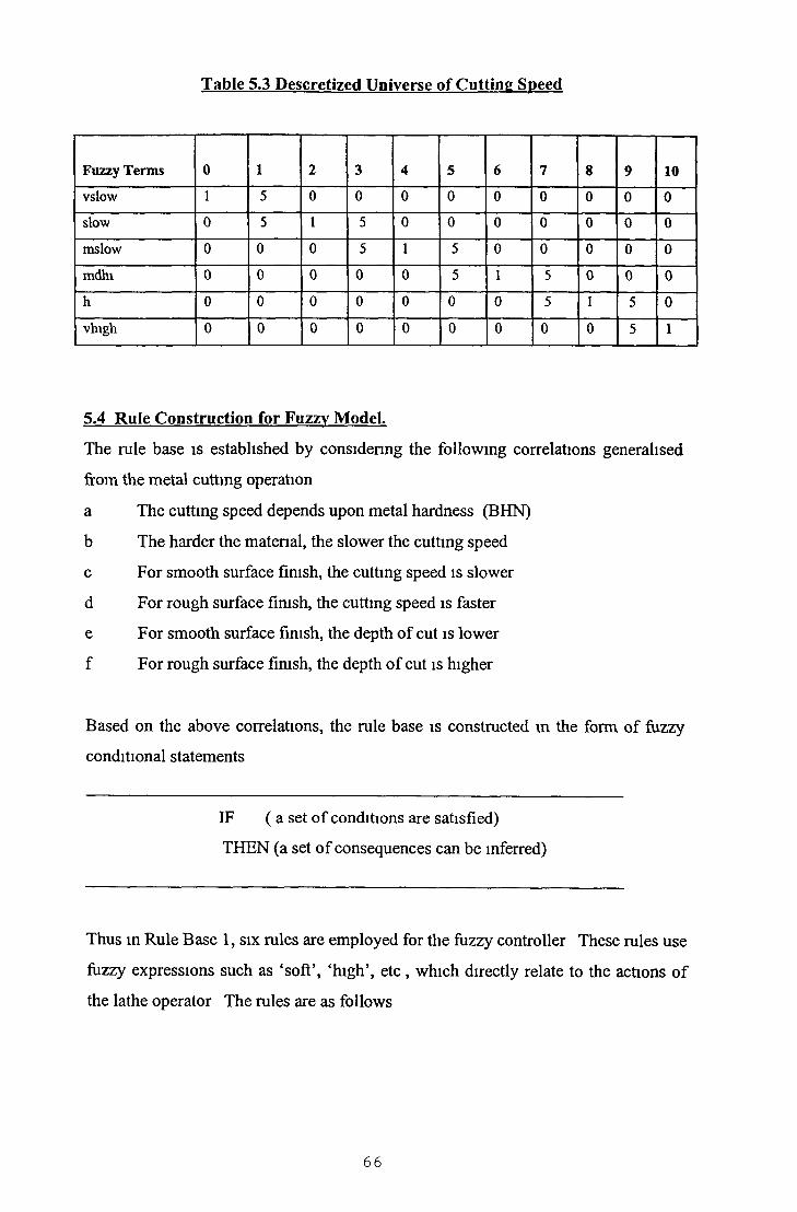
Table 5.3 Descretized Universe of Cutting Speed
Fuzzy Terms 0 1 2 3 4 5 6 7 8 9 10
vslow 1 5 0 0 0 0 0 0 0 0 0
slow 0 5 1 5 0 0 0 0 0 0 0
mslow 0 0 0 5 1 5 0 0 0 0 0
mdhi 0 0 0 0 0 5 1 5 0 0 0
h 0 0 0 0 0 0 0 5 1 5 0
vhigh 0 0 0 0 0 0 0 0 0 5 1
5.4 Rule Construction for Fuzzy Model.
The rule base is established by considering the following correlations generalised
from the metal cutting operation
a The cutting speed depends upon metal hardness (BHN)
b The harder the material, the slower the cutting speed
c For smooth surface finish, the cutting speed is slower
d For rough surface finish, the cutting speed is faster
e For smooth surface finish, the depth of cut is lower
f For rough surface finish, the depth o f cut is higher
Based on the above correlations, the rule base is constructed in the form of fuzzy
conditional statements
IF ( a set o f conditions are satisfied)
THEN (a set o f consequences can be inferred)
Thus in Rule Base 1, six rules are employed for the fuzzy controller These rules use
fuzzy expressions such as ‘soft’, ‘high’, etc , which directly relate to the actions o f
the lathe operator The rules are as follows
66

RULES IFHARDNESS
THENCUTTING SPEED
R ll VS (very soft) VHIGH (very high speed)
R12 SO (soft) HI (high speed)
R13 MED (medium) MDHI (medium high speed)
R14 MH (medium hard) MSLOW (medium slow speed)
R15 HA (hard) SLOW (slow speed)
R16 VA (very hard) VLSOW (very slow speed)
The input to the system is the material hardness (BHN) and output is the cutting
speed The input universe o f hardness is partitioned into 0 -20 umts and the output
universe o f cutting speed is split into 0 - 1 0 units or segments The choice of
number o f segments has an essential influence on how fine a control can be
obtained, that is the number o f segments determine the control resolution For
example, if a universe o f discourse is quantised for every ten units of measurements
instead o f twenty units, then the controller is twice as sensitive to the observed
variables
5.5 Fuzzy Relation for Metal Cutting.
Now the procedure to establish the fuzzy relations between Input1 and Output1 for
the Rule Base 1 by using e g (3-22) and (3-23) from Chapter 3 in the metal cutting
process are as follows
Referring to Table 5 4,
INPUT1 = “HARDNESS”
OUTPUT1 = “CUTTING SPEED”
For the first rule R ,, in the rule base 1 the fuzzy input term for INPUT1 is “VS” and
the fuzzy output term for OUTPUT1 IS ‘VHIGH’ Thus refemng to Table (5 2) the
fuzzy set ‘VS’ can be defined as
67

i
n [VS] = 1/10 + 75/1 + 50/2-^ 25/3 + 0/4 + 0/5 + 0/20 (5-1)
and referring to Table 5 3 the fuzzy set ‘VHIGH’ can be defined as
|i [VHIGH] = 0/0 + 0/1 + 0 /8 + 5 /9 + 1 /1 0 (5-2)
To find the relation between VS (very soft) and VHIGH (very high) one may
substitute eq (5-1) and (5-2) into eq (3-22) in Chap 3 and obtain the following -
68

Table 5.5 uRn
Universe of Cutting Speed
0 1 2 3 4 5 6 7 8 9 10
0 0 0 0 0 0 0 0 0 0 5 1
1 0 0 0 0 0 0 0 0 0 .5 75
2 0 0 0 0 0 0 0 0 0 .5 5
3 0 0 0 0 0 0 0 0 0 .25 25
4 0 0 0 0 0 0 0 0 0 0 0
5 0 0 0 0 0 0 0 0 0 0 0
6 0 0 0 0 0 0 0 0 0 0 0
7 0 0 0 0 0 0 0 0 0 0 0
8 0 0 0 0 0 0 0 0 0 0 0
9 0 0 0 0 0 0 0 0 0 0 0
10 0 0 0 0 0 0 0 0 0 0 0
11 0 0 0 0 0 0 0 0 0 0 0
12 0 0 0 0 0 0 0 0 0 0 0
13 0 0 0 0 0 0 0 0 0 0 0
14 0 0 0 0 0 0 0 0 0 0 0
15 0 0 0 0 0 0 0 0 0 0 0
16 0 0 0 0 0 0 0 0 0 0 0
17 0 0 0 0 0 0 0 0 0 0 0
18 0 0 0 0 0 0 0 0 0 0 0
19 0 0 0 0 0 0 0 0 0 0 0
20 0 0 0 0 0 0 0 0 0 0 0
In a similar manner Table 5 6 for Rule h r12 has been established and the relationship
o f the third, fourth and fifth and sixth rules can be developed

Table 5.6 Rp
Universe of Cutting Speed
Unlverse
of
Meta1
Hard
ess
Thus the second relation ( jlxR |2) can be combined only when an input is such that it is
within the ‘SO’ (Soft) hardness classification and allows the ‘HIGH’ cutting speed
value to be inferred It is obvious that the first and second relationships may be
combined to produce one which allows an input to be either VS or SO The
combination operator may be assumed to be ‘OR’ function which is represented as
0 1 2 3 4 5 6 7 8 9 10
0 0 0 0 0 0 0 0 0 0 0 0
1 0 0 0 0 0 0 0 25 25 25 0
2 0 0 0 0 0 0 0 5 5 5 0
3 0 0 0 0 0 0 0 5 75 5 0
4 0 0 0 0 0 0 0 5 1 5 0
5 0 0 0 0 0 0 0 5 75 5 0
6 0 0 0 0 0 0 0 5 5 5 0
7 0 0 0 0 0 0 0 25 25 25 0
8 0 0 0 0 0 0 0 0 0 0 0
9 0 0 0 0 0 0 0 0 0 0 0
10 0 0 0 0 0 0 0 0 0 0 0
11 0 0 0 0 0 0 0 0 0 0 0
12 0 0 0 0 0 0 0 0 0 0 0
13 0 0 0 0 0 0 0 0 0 0 0
14 0 0 0 0 0 0 0 0 0 0 0
15 0 0 0 0 0 0 0 0 0 0 0
16 0 0 0 0 0 0 0 0 0 0 0
17 0 0 0 0 0 0 0 0 0 0 0
18 0 0 0 0 0 0 0 0 0 0 0
19 0 0 0 0 0 0 0 0 0 0 0
20 0 0 0 0 0 0 0 0 0 0 0
70

the maximum of the membership value of the two different relations The fuzzy
statement combined from two fuzzy rules
(J.R,, and (j.R12 will be
IF HARDNESS IS ‘VS’ THEN CUTTING SPEED IS ‘VHIGH’ OR
IF HARDNESS IS ‘SO’ THEN CUTTING SPEED IS ‘HIGH’
Which is equivalent to p.R) i, + p.R)2 = Max {|a.Rn , fiR^}
and is represented m the following Table 5 7 (by using the eq (3-23) in Chap 3
Thus the total combination o f the six relations using ‘OR’ operator is the maximum
o f the memberships Thus the fuzzy algorithmi
IF HARDNESS = VS THEN SPEED = VHIGH OR
IF HARDNESS = SO THEN SPEED = HIGH OR
IF HARDNESS = MED THEN SPEED = MDHI OR
IF HARDNESS = MH THEN SPEED = MSLOW OR
IF HARDNESS = HA THEN SPEED = SLOW OR
IF HARDNESS = VA THEN SPEED = VSLOW
Can be represented m the relation (J.R1 which has a membership function of
jxRl = Max { p.Rn» HRi2> f ^ i 3, 1^14,^15,1^16,}
Hence using eq (3-23) m Chap 3 one can obtain the membership function as shown
m Table 5 8, for the relations between the “hardness” and the “cutting speed” in rule
base 1
71

Table 5.7 nRy_+ fiRi;
Universe of Cutting Speed
0 1 2 3 4 5 6 7 8 9 10
0 0 0 0 0 0 0 0 0 0 5 1
1 0 0 0 0 0 0 0 25 25 5 75
u2 0 0 0 0 0 0 0 5 5 5 5
n 3 0 0 0 0 0 0 0 5 75 5 .25lV
4 0 0 0 0 0 0 0 5 1 .5 0
e 5 0 0 0 0 0 0 0 5 75 .5 0rs
6 0 0 0 0 0 0 0 5 5 .5 0
e 7 0 0 0 0 0 0 0 25 25 25 0
of 8 0 “0 0 0 0 0 0 0 0 0 0
Me
9 0 0 0 0 0 0 0 0 0 0 0
10 0 0 0 0 0 0 0 0 0 0 0ta
11 0 0 0 0 0 0 0 0 0 0 0
1 12 0 0 0 ’ 0 0 0 0 0 0 0 0
H13 0 0 0 0 0 0 0 0 0 0 0
a 14 0 0 0 0 0 0 0 0 0 0 0rd
15 0 0 0 0 0 0 0 0 0 0 0
n 16 0 0 0 0 0 0 0 0 0 0 0
s 17 0 0 0 0 0 0 0 0 0 0 0
s 18 0 0 0 0 0 0 0 0 0 0 0
19 0 0 0 0 0 0 0 0 0 0 0
20 0 0 0 0 0 0 0 0 0 0 0
Using the same method, the rest membership function, \xRn, p .R14 ^ r i5 and ^ R ,6 can
be obtained
72

Table 5.8 Membership Function for Rule Base 1
Universe of Cutting Speed
0 1 2 3 4 5 6 7 8 9 100 0 0 0 0 0 0 0 0 0 5 1
1 0 0 0 0 0 0 0 25 25 5 75
2 0 0 0 0 0 0 0 .5 5 5 5
3 0 0 0 0 0 0 0 5' 75 5 25
4 0 0 0 0 0 0 0 5 1 5 0
5 0 0 0 0 0 25 25 5 75 5 0
6 0 0 0 0 0 5 5 .5 5 5 0
7 0 0 0 0 0 5 75 5 25 25 0
8 0 0 0 0 0 5 1 5 0 0 0
9 0 0 0 25 25 .5 75 5 0 0 0
10 0 0 0 5 5 5 5 5 0 0 0
11 0 0 0 5 75 5 25 25 0 0 0
12 0 0 0 5 1 5 5 0 0 0 0
13 0 25 25 5 75 5 0 0 0 0 0
14 0 5 5 5 5 5 0 0 0 0 0
15 0 5 75 5 25 25 0 0 0 0 0
16 0 5 1 5 0 0 0 0 0 0 0
17 25 5 75 5 0 0 0 0 0 0 0
18 5 5 5 5 0 0 0 0 0 0 019 75 5 25 25 0 0 0 0 0 0 020 1 5 0 0 0 0 0 0 0 0 0
i
This relation is the model o f the action o f the machine tool operator Combimng this
relation with any value o f the material hardness that lies in its universe [0-20] results
in the required average speed output as follows
73

The defuzzified output which gives the average speed value can be obtained by using the eq (3-24) in Chap 3, which is average valúe = £ speed value x n(sYX|
For a hardness universe ‘7’ for example the average speed result would be
Speed Value = 5 x 5 + 75 x 6 + 5 x 7 + 25 x 8 + 25 x 95 + 75 + 5 + 25+ 25
= 14 75 = 6 56 2 25
The following Table 5 9 gives the relationship between the hardness [0-20] and the
average values o f output speed
Average Speed Values for Cutting Speed
Table 5.9
H ardness Universe Partitioning
Average Speed Values
0 9 671 9 002 8 503 8 254 8 005 7 446 7 007 6 568 6 009 5 4410 5 0011 4 5612 4 0013 3 4414 3 0015 2 5616 2 0017 1 7518 1 5019 1 0020 0 33
I k

J
5.6 Theoretical Results using Fuzzv (model-1) and Discussions for Free
machining Carbon wrought Steel.
Figures 5 5 and 5 5a show two different graphical presentation o f the same results
obtained by applying Fuzzy Model-1 to free machining carbon wrought steel and
using a high speed steel tool at a depth o f cut o f 1mm HARDNESS is represented
on the x-axis and SPEED is represented on the y-axis In Figure 5 5 the fuzzy
cutting speed values are plotted along with the upper and lower band limits o f the
cutting speed These upper and lower band limits o f the cutting speed are obtained
by plotting the data from the machining data handbook [99]
In Figure 5 5a the fuzzy cutting speed values are plotted in an alternative manner
along with the speed range obtained from the machining data handbook [99], where
the workpiece materials are grouped according to their material hardness (BHN) and
one particular speed is applicable to that hardness range For example, when the
matenal hardness range is between 225 to 275, the prescribed cutting speed is 49
m/min and for hardness values between 275 to 325, the prescribed cutting speed is
41 m/mm
Either o f the two different graphical presentations m Figure 5 5 and 5 5a can be used
for presenting all the results obtained m this study Therefore, the graphical
presentation with the upper and lower band limit will be used to present the rest of
the results o f this thesis
As can be seen from Figure 5 5 that the fuzzy cutting speeds values obtained using
Fuzzy Model 1 for Free Machining carbon wrought steel at a depth o f cut 1 mm and
using a high speed steel tool, generally lie within the band o f the machining data
However, the cutting speed for lower hardness value fall a little below the lower
limit o f the experimental data band and the fuzzy cutting speed for higher hardness
value fall a little above the upper limit o f the data band The hardness value used for
this calculation is 225 to 425 and speed value used is 21 to 49 m/min taking from the
machining data handbook [99]
75

It would be desirable that the cutting speed values according to the fuzzy model
should be in between the lower and upper limit o f the expenmental data band It
was therefore felt that tuning would be required to make these fuzzy cutting speed
values lie along the midrange o f the data band To achieve this, the appropriate
cutting speed for the midpoint o f the hardness range is used Therefore the hardness
value used for depth o f cut 1 mm (Free machining carbon wrought steel), using a
high speed steel tool, is 250 to 400 and cutting speed is 21 to 49 For example,
previously, the cutting speed value o f 49 m/nun was assigned for the hardness o f
225 for fuzzy logic model even though this cutting speed is prescribed for the
hardness range 225 to 275 according to expenmental data In the revised approach,
the cutting speed o f 49 m/min has been assigned for 250 (mid value o f hardness
range) for the fuzzy calculation These new fuzzy cutting speed values are plotted in
Figure 5 6 As can be seen from Figure 5 6 the fuzzy cutting speed values he nicely
at the middle o f the upper and lower limit o f data band, showing very good fuzzy
presentation The same technique was used for the rest o f the calculations for both
matenals, at three different depths o f cut 1 mm, 4 mm and 8 mm and using four
different cutting tools - 1) High speed steel tool, 11) Carbide tool-coated, 111) Carbide
tool-uncoated brazed and iv ) Carbide tool-uncoated indexable
The results o f the calculations obtained for free machining carbon wrought steel at
three different depths o f cut (1mm, 4mm and 8mm) and using four different types o f
cutting tools are shown in Table 5 10 , Table 5 11 and Table 5 12 respectively
76

Cut
ting
sp
eed
m/m
in.
2 0 0 2 5 0 3 0 0 35 0 4 0 0 4 5 0 5 00
M e ta l h a r d n e s s (B H N )
F ig 5.5 F u z z y c u t t i n g s p e e d f o r F r e e m a c h i n i n g c a r b o nw r o u g h t s t e e l a t d.o c 1 mm u s i n g H i g h s p e e d t e e l t oo l
( m o d e l - 1)
77
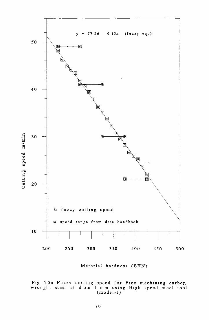
Cut
ting
sp
eed
m/m
in
200 2 5 0 300 350 400 450 500
M a te r i a l h a r d n e s s (B H N )
Fi g 5.5a F u z z y c u t t i n g s p e e d f o r F r e e m a c h i n i n g c a r b o nw r o u g h t s t e e l at d o.c 1 mm u s i n g H i g h s p e e d s t e e l t oo l
( m o d e l - 1)
78

Table 5.10 Fuzzy Cutting Speed for
Free Machining Carbon W rought Steel
(D.O.C. = 1mm)
(BHN) H SS.T C .T .C C.T .U .B . C .T .U .I.225 52 33 291.30 155 95 192 73
235 50 60 285 42 152 85 188 71245 48 86 279 54 149 76 184 69255 47 13 273.66 146 66 180 66265 45 40 267 78 143 57 176 64275 43 66 261 90 140 47 172 61285 41 93 256 02 137 38 168 59295 40 20 250 14 134 28 164 57305 38 46 244 26 131 19 160 54315 36 73 238 38 128 09 156 52325 35 00 232 50 125 00 152 50335 33 26 226 61 121 90 148 47345 31 53 220 73 118 80 144 45355 29 79 214 85 115 71 140 42365 28 06 208 97 112 6 1 136 40375 26 33 203 09 109.52 132 38385 24 59 197 21 106 42 128 35395 22 86 191 33 103 33 124 33405 21 13 185 45 100 23 120 30415 19 39 179 57 97 14 116 28425 17 66 173 69 94 04 112 20
Where D O C . = Depth o f CutBHN = Material hardness HSS T = High Speed Steel Tool
Tool C T C = Carbide Tool-CoatedUsed C T U B = Carbide Tool-Uncoated brazed
C T U I = Carbide Tool-Uncoated Indexable
79

Table 5.11 Fuzzy Cutting Speed for
Free Machining Carbon W rought Steel
(D.O.C. = 4mni>
B H N H SST C .T .C . C .T .U .B . C .T .U .I.225 40 50 192 73 125.23 150 95235 39 20 188.71 122 51 147 85245 37 90 184 69 119 79 144 76255 36 60 180 66 117 06 141 66265 35.30 176 64 114 34 138 57275 34 00 172 61 111.61 135 47285 32 70 168 59 108 89 132 38295 31 40 164 57 106 17 129 28305 30 10 160 54 103 44 126 19315 28 80 156 52 100 72 123 09325 27.50 152.50 97.99 120 00335 26 20 148 47 95 27 116 90345 24 90 144.45 92 55 113 80355 23 60 140.42 89 82 110 7 1365 22 30 136 40 87 10 107 61375 21 00 132 38 84 38 104 52385 19 70 128 35 81 65 101 42395 18 40 124 33 78 93 98 33405 17 10 120.30 76 20 95 23415 15 80 116 28 73 48 92 14425 14.50 112 26 70 76 89 04
Where D O C = Depth o f CutBHN = Material hardness
HSS T = High Speed Steel Tool Cutting Tool C T C = Carbide Tool-Coated Material C T.U B = Carbide Tool-Uncoated brazed
C T U I = Carbide Tool-Uncoated Indexable
80

Table 5.12 F uzzy Cutting Speed for
Free Machining Carbon W rought Steel
(D.O.C. = 8mm)
BH N H SST C .T .C . C.T .U .B . C.T .U .I.225 31 90 155 95 99 16 120 00235 30 91 152 85 97 00 117 40245 29 92 149 76 94 83 114 80255 28 93 146 66 92 66 112 20265 27 94 143 57 90 50 109 60275 26 95 140 47 88 33 107 00285 25 96 137 38 86 16 104 40295 24 97 134 28 84 00 101 80305 23 98 131 19 81 83 99 20315 22 99 128 09 79 66 96 60325 22 00 125 00 77 50 94 00335 21 00 121 90 75 33 91 40345 20 01 118 80 73 16 88 80355 19 02 115 71 71 00 86 20365 18 03 11261 68 83 83 60375 17 04 109 52 66 66 81 00385 16 05 106 42 65 50 78 40395 15 06 103 33 62 33 75 80405 14 07 100 23 60 16 73 20415 13 08 97 14 58 00 70 60425 12 09 94 04 55 83 68 00
Fig 5 6 to Fig 5 17 shows the graphical presentation o f the results obtained by
applying Fuzzy Model 1 Fig 5 6 shows the results using a high speed steel cutting
tool and depth o f cut o f 1mm The relationship between the cutting speed and
hardness shown m this figure can be represented by the equation
Y = 9 1 3 4 - 0 1 7 X ( 5 - 3 )
Fig 5 7 shows the results using a high speed steel cutting tool and depth o f cut of
4mm The relationship between the cutting speed and hardness shown in this figure
can be represented by the equation
Y = 69 75 - 0 13X (5 -4 )
81

Fig 5 8 shows the results using a high speed steel cutting tool and depth o f cut of
8mm. The relationship between the metal hardness and cutting speed shown m this
figure can be represented by the equation
Y = 54 1 9 - 0 10 X . . . ( 5 - 5 )
Fig 5 9 shows the results using a carbide coated tool and depth o f cut o f 1mm The
relationship between the metal hardness and cutting speed shown in this figure canr
be represented by the equation
Y = 423 62 - 0 59X . ( 5 - 6 )
Fig 5 10 shows the results using a carbide coated tool and depth o f cut o f 4mm The
relationship between the cutting speed and metal hardness (BHN) shown in this
figure can be represented by the equation
Y = 283 27 - 0 40X . ( 5 - 7 )
Fig 5 11 shows the results using a Carbide coated tool and depth of cut o f 8mm The
relationship between the cutting speed and hardness shown in this figure can be
represented by the equation
Y = 225 60 - 0 31X . . (5 -8 )
Fig 5 12 shows the results using a carbide tool-uncoated brazed and depth o f cut o f
1mm The relationship between the cutting speed and hardness shown m this figure
can be represented by the equation
Y = 225 60 - 0 31X . ( 5 - 9 )
Fig 5.13 shows the results using a Carbide tool-uncoated brazed and depth o f cut o f
4mm The relationship between the cutting speed and hardness shown in this figure
can be represented by the equation
Y = 186 52 -t) 27X (5 -10)
82

Fig 5.14 shows the results using a Carbide tool-uncoated brazed and depth of cut of
8mm. The relationship between the cutting speed and hardness shown in this figure
can be represented by the equation
Y = 147.71 - 0 .22X ....................... (5 - 11)
Fig 5.15 shows the results using a Carbide tool-uncoated indexable and depth o f cut
o f 1mm. The relationship between the cutting speed and hardness shown in this
figure can be represented by the equation
Y = 283.27-0 .4 0 X ........................ (5 - 12)
Fig 5.16 shows the results using a Carbide tool-uncoated indexable and depth o f cut
o f 4mm. The relationship between the hardness and cutting speed shown in this
figure can be represented by the equation
Y = 220.60 - 0.3I X ......................... (5-13)
Fig 5.17 shows the results using a Carbide tool-uncoated indexable and depth o f cut
o f 8mm. The relationship between the cutting speed and hardness shown in this
figure can be represented by the equation
Y = 178.50 - 0 .26X ......................... (5 - 14)
Figures 5.6 to 5.8 represents the fuzzy cutting speeds obtained for Free machining
carbond wrought steel at three depth of cut 1mm, 4 mm and 8 mm and using High
Speed steel tool. Figures 5.9 to 5.11 represents the fuzzy cutting speeds obtained for
Free machining carbon wrought steel at depth o f cut 1 mm, 4 mm and 8 mm and
using a carbide coated tool. Figures 5.12 to 5.14 represents the fuzzy cutting speeds
using a carbide tool uncoated brazed at three depth o f cut 1 mm, 4 mm and 8 mm for
Free machining carbon wrought steel. Figures 5.15 to 5.17 represents the fuzzy
cutting speeds obtained for Free machining carbon wrought steel at three depths of
cut 1mm, 4 mm and 8 mm and using a carbide tool- uncoated indexable.
83

Cut
ting
sp
eed
m/m
in
2 0 0 2 5 0 3 0 0 35 0 4 0 0 4 5 0 5 0 0
M ater ia l h a r d n e s s ( B H N )
F ig 5.6 F u z z y c u t t i n g s p e e d f o r F r e e m a c h i n i n g c a r b o nw r o u g h t s t e e l a t d o. c 1 m m u s i n g H i g h s p e e d s t e e l t oo l
( m o d e l - 1)
84

Cut
ting
sp
eed
m/m
in
2 0 0 2 5 0 3 00 3 50 4 0 0 45 0 50 0
M a t e r i a l h a r d n e s s ( B H N )
Fi g 5 7 F u z z y c u t t i n g s p e e d f o r F r e e m a c h i n i n g c a r b o nw r o u g h t s t e e l a t d . o . c 4 mm u s i n h H i g h s p e e d s t e e l t oo l
( m o d e l - 1)
85

Cut
ting
sp
eed
m/m
in
2 0 0 2 5 0 3 0 0 350 4 0 0 4 5 0 50 0
M a t e r i a l h a r d n e s s ( B H N )
Fi g 5.8 F u z z y c u t t i n g s p e e d f o r F r e e m a c h i n i n g c a r b o nw r o u g h t s t e e l a t d . o . c 8 mm u s i n g H i g h s p e e d s t e e l t oo l
( m o d e l - 1)
86

Cut
tinh
sp
eed
m/m
in350
y = 4 2 3 6 2 - 0 5 9 x ( f u z z y e q u )
2 0 0 2 5 0 3 0 0 35 0 4 0 0 45 0 500
M a t e r i a l h a r d n e s s ( B H N )
Fi g 5.9 F u z z y c u t t i n g s p e e d f o r F r e e m a c h i n i n g c a r b o nw r o u g h t s t e e l at d o c 1 mm u s i n g C a r b i d e c o a t e d t oo l
( m o d e l - 1)
87

Cut
ting
sp
eed
m/m
in
2 0 0 2 5 0 30 0 350 4 0 0 4 50 500
M a t e r i a l h a r d n e s s ( B H N )
Fi g 5.10 F u z z y c u t t i n g s p e e d f o r F r e e m a c h i n i n g c a r b o nw r o u g h t s t e e l a t d o c 4 mm u s i n g C a r b i d e c o a t e d t oo l
( m o d e l - 1)
88

Cut
ting
sp
eed
m/m
in
2 0 0 25 0 30 0 350 4 0 0 45 0 500
M a t e r i a l h a r d n e s s ( B H N )
Fi g 5.11 F u z z y c u t t i n g s p e e d f o r F r e e m a c h i n i n g c a r b o nw r o u g h t s t e e l at d o c 8 mm u s i n g C a r b i d e c o a t e d t oo l
( m o d e l - 1)
89

180
170
160
150
140
130
120
110
100
90
80
70
10 2 5 0 3 00 350 4 0 0 4 5 0 50
M a t e r i a l h a r d n e s s ( B H N )
I F u z z y c u t t i n g s p e e d f o r F r e e m a c h i n i n g c a r b o ns t ee l a t d . o . c 1 mm u s i n g C a r b i d e u n c o a t e d b r a z
t o o l ( mo d e l - 1 )
90

Cut
ting
sp
eed
m/m
in
2 0 0 2 5 0 3 0 0 35 0 4 0 0 4 50 500
M a t e r i a l h a r d n e s s ( B H N )
F i g 5.13 F u z z y c u t t i n g s p e e d f o r F r e e m a c h i n i n g c a r b o nw r o u g h t s t e e l at d o c 4 mm u s i n g C a r b i d e u n c o a t e d b r a z e d
t oo l ( m o d e l - 1 )
91
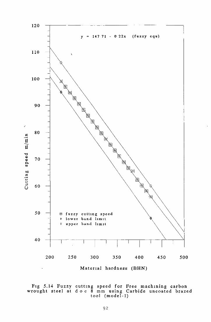
Cut
ting
sp
eed
m/m
in
2 0 0 2 5 0 30 0 3 50 4 0 0 4 5 0 5 00
M a t e r i a l h a r d n e s s ( B H N )
Fi g 5.14 F u z z y c u t t i n g s p e e d f o r F r e e m a c h i n i n g c a r b o nw r o u g h t s t e e l at d o c 8 mm u s i n g C a r b i d e u n c o a t e d b r a z e d
t oo l ( mo d e l - 1 )
92
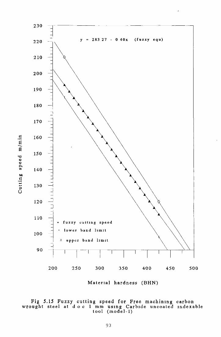
Cut
ting
sp
eed
m/m
in
2 0 0 2 5 0 30 0 35 0 4 0 0 45 0 50 0
M a t e r i a l h a r d n e s s ( B H N )
Fi g 5.15 F u z z y c u t t i n g s p e e d f o r F r e e m a c h i n i n g c a r b o nw r o u g h t s t e e l a t d o c 1 mm u s i n g C a r b i d e u n c o a t e d i n d e x a b l e
t oo l ( m o d e l - 1 )
93

180
170
160
150
140
130
120
110
100
90
80
70
y = 2 2 0 6 0 - 0 3 1 x ( f u z z y e q u )
10 2 5 0 30 0 350 4 0 0 4 5 0 50
M a t e r i a l h a r d n e s s ( B H N )
6 F u z z y c u t t i n g s p e e d f o r F r e e m a c h i n i n g c a r b o iee l at d.o c 4 m m u s i n g C a r b i d e u n c o a t e d i n d e x
t oo l ( mo d e l - 1 )
94

140
130
120
110
100
90
80
70
60
50
Fig
y = 178 5 0 - 0 2 6 x ( f u z z y e q u )
0 f u z z y c u t t i n g s p e e d
+ l o w e r b a n d l i m i t
0 u p p e r b a n d l i m i t
10 2 50 300 350 4 0 0 450 50
M a t e r i a l h a r d n e s s ( B H N )
17 F u z z y c u t t i n g s p e e d f o r F r e e m a c h i n i n g c a r b ot e e l a t d.o c 8 mm u s i n g C a r b i d e u n c o a t e d i nde :
t oo l ( m o d e l - 1 )
95

From Figures 5 6 to 5 17 it can be seen that the fuzzy cutting speeds obtained by
applying the Fuzzy Model one are fitted nicely at the middle o f the expenmental
data band
Table 5 13 shows the actual data for medium carbon leaded steel that have been used
for calculations
Table 5.13 M achining Data for M edium C arbon Leaded Steel
SpeèdR ange m/min "
; D epth of C ut1 /
Tool Name
20-55 1mm High Speed Steel Tool (H S S T )17-43 4 mm11-34 8mm a
160-310 1mm Carbide Tool - Coated (C T C )105-205 4mm <<
84-160 8mm i i
87-170 1mm Carbide Tool-Uncoated Brazed (C T U I )67-130 4mm52-100 8mm
115-220 1mm Carbide Tool Uncoated Indexable (C T U I )85-170 4mm69-130 8mm
The results o f the calculations obtained for Medium carbon leaded steel at three
different depths o f cut 1mm, 4mm and 8mm and using four different types o f cutting
tools are shown m Table 5 14, Table 5 15 and Table 5 16 respectively
96

Table 5.14 - Fuzzv Cutting Speed for
Medium Carbon Leaded Steel
(D.O.C. = 1 mmi
(BHN) H.S.S.T C.T.C. C.T.U.B. C.T.U.I.
125 57 00 318 57 174 14 225.99
140 55 05 31021 170 11 220 14
155 53 10 301 85 165 49 214 29
170 51 15 293 50 160 87 208 44
185 49 20 285 14 156 24 202 59
200 47 25 276 78 151 62 196 75
215 45 30 268.42 146 99 190 90
230 43 35 260 07 142 37 185 05
245 41 40 251 71 137 74 179 20
260 39 45 243 35 133 12 173 35
275 37 50 235 00 128 50 167 50
290 35 55 226 64 123 87 161 65
305 33 60 218 28 119 25 155 80
320 31 65 209 92 114 62 149 95
335 29 70 201 57 110 00 144 10
350 27 75 193 21 105 37 138 25
365 25 79 184 85 100 75 132 40
380 23 84 176 50 96 12 126 55
395 21.89 168 14 91 50 120 70
410 19 94 159 78 86 88 114 85
425 17 99 151 42 82 25 109 00
Where D O C = Depth o f cutBHN = Material hardness
Tool H S S T = High speed steel toolMaterials C T C = Carbide tool-coated
C.T.U.B = Carbide tool-uncoated brazed C T U I = Carbide tool-uncoated indexable
97
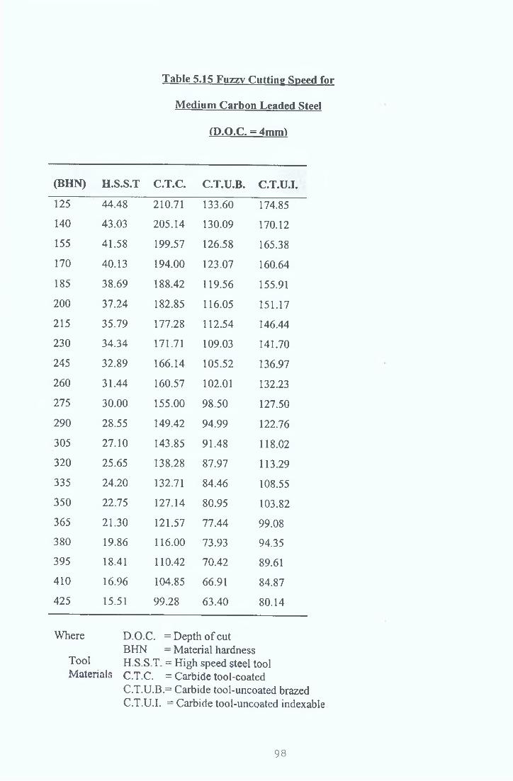
Table 5.15 Fuzzv Cutting Speed for
Medium Carbon Leaded Steel
(D.O.C. = 4mmi
(BHN) H.S.S.T C.T.C. C.T.U.B. C.T.U.I.
125 44.48 210.71 133.60 174.85
140 43.03 205.14 130.09 170.12
155 41.58 199.57 126.58 165.38
170 40.13 194.00 123.07 160.64
185 38.69 188.42 119.56 155.91
200 37.24 182.85 116.05 151.17
215 35.79 177.28 112.54 146.44
230 34.34 171.71 109.03 141.70
245 32.89 166.14 105.52 136.97
260 31.44 160.57 102.01 132.23
275 30.00 155.00 98.50 127.50
290 28.55 149.42 94.99 122.76
305 27.10 143.85 91.48 118.02
320 25.65 138.28 87.97 113.29
335 24.20 132.71 84.46 108.55
350 22.75 127.14 80.95 103.82
365 21.30 121.57 77.44 99.08
380 19.86 116.00 73.93 94.35
395 18.41 110.42 70.42 89.61
410 16.96 104.85 66.91 84.87
425 15.51 99.28 63.40 80.14
Where D.O.C. = Depth o f cutBHN - Material hardness
Tool H.S.S.T. = High speed steel toolMaterials C.T.C. = Carbide tool-coated
C.T.U.B.= Carbide tool-uncoated brazed C.T.U.I. = Carbide tool-uncoated indexable
98

Table 5.16 Fuzzy Cutting Speeds for
Medium Carbon Leaded Steel
(D .O .C . = 8 m m i
(B H N ) H .S .S .T C .T .C . C .T .U .B . C .T .U .I .
125 35 31 164 34 102 74 133 48140 34 03 160 10 100 06 130 08
155 32 75 155 87 97 39 126 68
170 31 47 151 64 94 72 123 29
185 30 18 147 40 92 04 119 89
2 0 0 28 90 143 17 89 37 116 49
215 2 7 62 138 93 86 69 113 09
2 3 0 26 34 134 70 84 02 109 69
245 25 06 130 46 81 34 106 29
2 6 0 23 78 126 23 78 67 102 89
275 22 50 122 00 76 00 99 50
2 9 0 21 21 117 76 73 32 96 10
305 19 93 113 53 70 65 92 70
3 2 0 18 65 109 29 67 97 89 30
335 17 37 105 06 65 30 85 90
3 5 0 16 09 100 82 62 62 82 50
365 14 81 96 59 59 95 79 10
3 8 0 13 53 92 35 57 28 75 70
395 12 24 88 12 54 60 72 31
4 1 0 10 96 83 89 51 93 68 91
425 9 68 79 65 49 25 65 51
Where D O C = Depth o f cutBHN = Material hardness
Tool h S S T = High speed steel toolMaterials C T C = Carbide tool-coated
C T U B = Carbide tool-uncoated brazed C T U I = Carbide tool-uncoated indexable
99
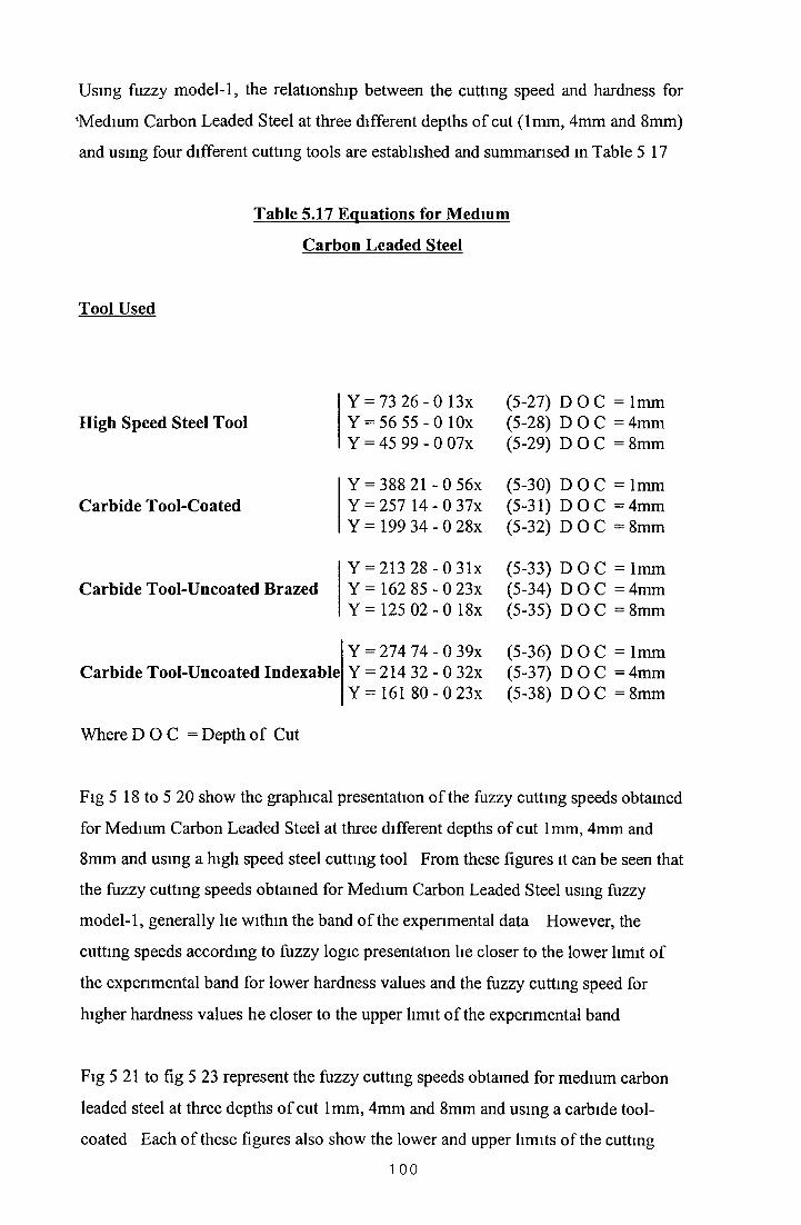
Using fuzzy model-1, the relationship between the cutting speed and hardness for
'Medium Carbon Leaded Steel at three different depths of cut (1mm, 4mm and 8mm)
and using four different cutting tools are established and summarised in Table 5 17
Table 5.17 Equations for Medium
Carbon Leaded Steel
Tool Used
High Speed Steel Tool
Carbide Tool-Coated
Carbide Tool-Uncoated Brazed
Carbide Tool-Uncoated Indexable
Y = 73 2 6 - 0 13x (5-27) D O C = 1mmY = 56 55 -0 lOx (5-28) D O C = 4mmY = 45 99 - 0 07x (5-29) D O C = 8mm
Y = 388 21 - 0 56x (5-30) D O C = 1mmY = 257 1 4 - 0 37x (5-31) D O C = 4mmY = 199 3 4 - 0 28x (5-32) D O C = 8mm
Y = 213 28 -0 31x (5-33) D O C = 1mmY = 162 85 -0 23x (5-34) D O C = 4mmY = 125 0 2 - 0 18x (5-35) D O C = 8mm
Y = 274 74 - 0 39x (5-36) D O C = 1mmY = 214 3 2 - 0 32x (5-37) D O C = 4mmY = 161 8 0 - 0 23x (5-38) D O C = 8mm
Where D O C = Depth o f Cut
Fig 5 18 to 5 20 show the graphical presentation o f the fuzzy cutting speeds obtained
for Medium Carbon Leaded Steel at three different depths of cut 1mm, 4mm and
8mm and using a high speed steel cutting tool From these figures it can be seen that
the fuzzy cutting speeds obtained for Medium Carbon Leaded Steel using fuzzy
model-1, generally lie within the band o f the experimental data However, the
cutting speeds according to fuzzy logic presentation lie closer to the lower limit of
the experimental band for lower hardness values and the fuzzy cutting speed for
higher hardness values he closer to the upper limit o f the experimental band
Fig 5 21 to fig 5 23 represent the fuzzy cutting speeds obtained for medium carbon
leaded steel at three depths o f cut 1mm, 4mm and 8mm and using a carbide tool-
coated Each of these figures also show the lower and upper limits of the cutting
1 0 0

speed band obtained by plotting the data from the machining data hand book [9 9 ].
From the figures it can be seen that the cutting speed values obtained from the fuzzy
model 1 generally lie towards the middle o f the band o f the machining data.
The fuzzy cutting speeds presentation for 1mm and 8 mm in Figs. 5.21 and 5.23 fall
almost at the middle o f the experimental data band, whereas the fuzzy cutting speed
for 4 mm in Fig. 5.22 has slight tendency to go closer to the upper band o f the
cutting speed data for higher hardness values.
Figs 5.24 to 5.26 show the graphical presentation o f the fuzzy cutting speeds
obtained for medium carbon leaded steel at three depths o f cut 1mm, 4mm and 8mm
and using a carbide tool-uncoated brazed. Each o f these figures also presents the
lower and upper limits o f the cutting speed band obtained by plotting the data from
reference [99]. From these figures it can be seen that the fuzzy cutting speeds fall
within the lower and the upper limit o f the data band.
The fuzzy cutting speeds for depth o f cut o f 1 mm and 8 mm in Figs. 5.24 and 5.26
respectively lie at the middle o f the experimental lower and upper band limits o f the
cutting speed. For depth o f cut o f 4 mm in Fig. 5.23 the cutting speed values for
higher hardness values have little inclination towards the upper band limit whereas
the cutting speed values for lower hardness values have tendency for staying close to
the lower band limit o f the experimental data.
Figs 5.27 to 5.29 represent the fuzzy cutting speeds obtained for medium carbon
leaded steel at three depths o f cut 1mm, 4mm, 8mm and using a carbide tool-
uncoated indexable. Each o f these figures also shows the lower and upper limits o f
the experimental data obtained by plotting from reference [99]. From the graphical
representation it shows that the fuzzy cutting speeds obtained from the fuzzy model
1 lie reasonably within the lower and upper limit o f the experimental data band. But
the fuzzy cutting speed for lower hardness value at depth o f cut o f 1 mm in Fig.
5.27 fall close to the lower limit and the fuzzy cutting speed for higher hardness
value fall close to the upper limit o f the experimental data band.
101
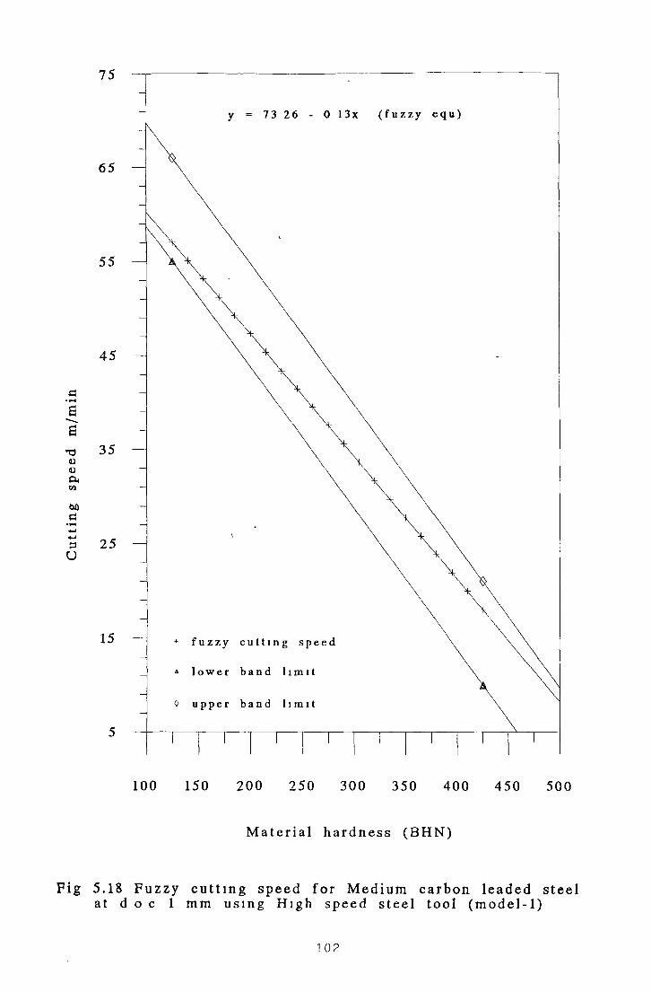
Cu
ttin
g sp
eed
m/m
in75
y = 73 26 - 0 13x ( f u z z y e q u )
1 0 0 1 5 0 2 0 0 2 5 0 3 0 0 3 5 0 4 0 0 4 5 0 5 0 0
M a t e r i a l h a r d n e s s ( B H N )
F ig 5.18 F u z z y c u t t i n g s p e e d f o r M e d i u m c a r b o n l e a d e d s t e e la t d o c 1 m m u s i n g Hi g h s p e e d s t e e l t oo l ( mo d e l - 1 )
1 02

Cut
ting
sp
eed
m/m
in
100 150 2 0 0 2 5 0 3 0 0 35 0 4 0 0 4 5 0 500
M a t e r i a l h a r d n e s s ( B H N )
Fi g 5 .19 F u z z y c u t t i n g s p e e d f o r M e d i u m c a r b o n l e a d e d s t e e lat d . o . c 4 mm u s i n g H i g h s p e e d s t e e l t o o l ( mo d e l - 1 )
1 03

Cut
ting
sp
eed
m/m
in
100 2 0 0 3 0 0 4 0 0 500
M a t e r i a l h a r d n e s s ( B H N )
Fi g 5. 20 F u z z y c u t t i n g s p e e d f o r M e d i u m c a r b o n l e a d e d s t e e la t d . o . c . 8 mm u s i n g Hi g h s p e e d s t e e l t oo l ( mo d e l - 1 )
1 04

Cut
ting
sp
eed
m/m
in
100 150 2 0 0 2 5 0 3 0 0 3 50 4 0 0 4 5 0 50 0
M a t e r i a l h a r d n e s s ( B H N )
F i g 5.21 F u z z y c u t t i n g s p e e d f o r M e d i u m c a r b o n l e a d e d s t e e lat d . o . c 1 mm u s i n g C a r b i d e c o a t e d t oo l ( mo d e l - 1 )
1 05
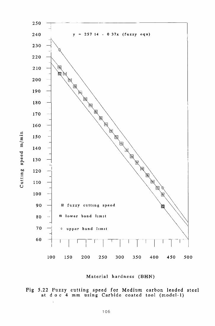
25 0
2 4 0
2 3 0
220
210
2 0 0
190
180
170
160
150
140
130
120
110
100
90
80
70
60
g 5,
y = 2 5 7 1 4 - 0 3 7 x ( f u z z y e q u )
0 150 2 0 0 25 0 30 0 35 0 4 0 0 4 5 0 5C
M a t e r i a l h a r d n e s s ( B H N )
F u z z y c u t t i n g s p e e d f o r M e d i u m c a r b o n l e a d e do c 4 m m u s i n g C a r b i d e c o a t e d t o o l ( mo d e l - 1 )
s
1 06
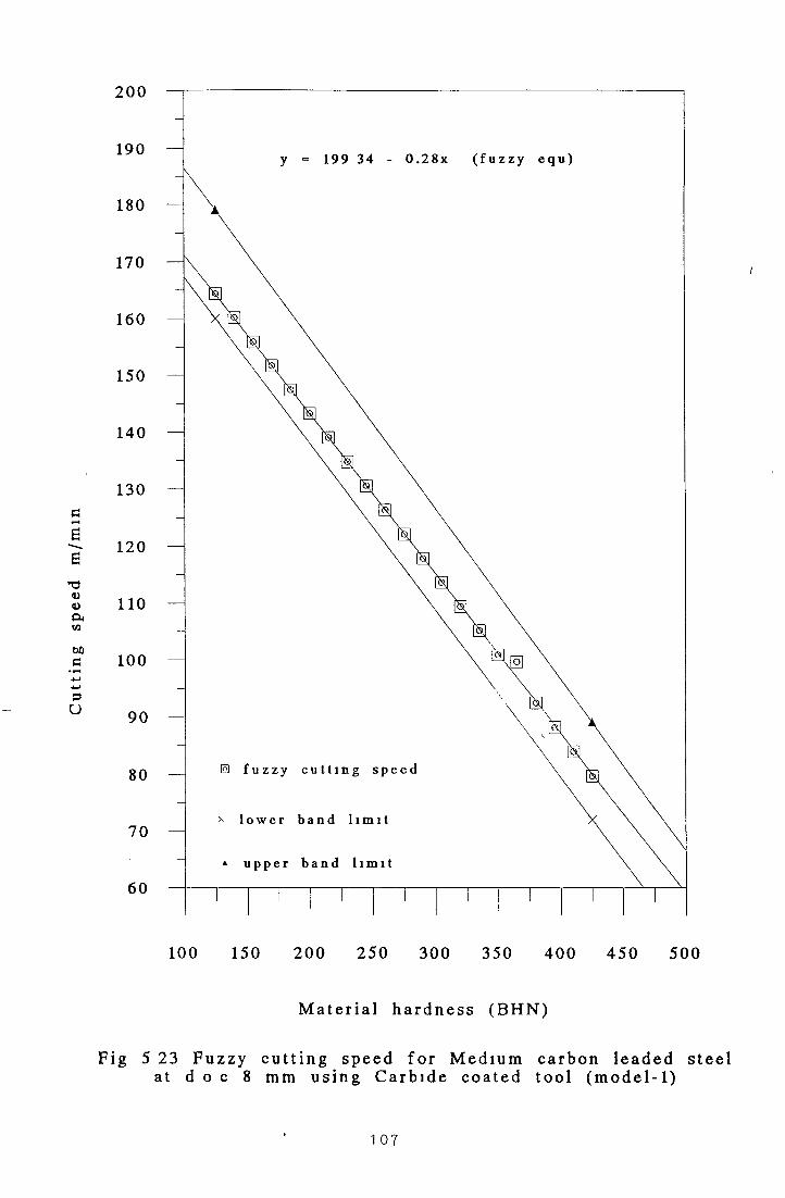
190
180
170
160
150
140
130
120
110
100
90
80
70
60
R 5
y - 199 3 4 - 0 . 2 8 x ( f u z z y e q u )
3 150 2 0 0 2 5 0 30 0 350 4 0 0 4 5 0 5
M a t e r i a l h a r d n e s s ( B H N )
F u z z y c u t t i n g s p e e d f o r M e d i u m c a r b o n l e a d e dd o c 8 mm u s i n g C a r b i d e c o a t e d t o o l ( m o d e l - 1 )
1 0 7

2 0 0
190
180
170
160
150
140
130
120
110
100
90
80
70
60
5 . 24d o c
y - 2 1 3 2 8 - 0 3 1 x ( f u z z y e q u )
f u z z y c u t t i n g s p e e d
l o w e r b a n d l i m i t
o u p p e r b a n d l i m i t
0 150 2 0 0 2 5 0 3 0 0 350 4 0 0 4 5 0 50
M a t e r i a l h a r d n e s s ( B H N )
j z z y c u t t i n g s p e e d f o r M e d i u m c a r b o n l e a d e d st(mm u s i n g C a r b i d e u n c o a t e d b r a z e d t o o l ( m o d e l -
1 08

160
150
140
130
120
110
100
90
80
70
60
50
40
5.2d o
y - 1 6 2 8 5 - 0 2 3 x ( f u z z y e q u )
f u z z y c u t t i n g s p e e d
+ l o w e r b a n d l i m i t
0 u p p e r b a n d l i m i t
0 150 2 0 0 2 5 0 3 0 0 350 4 0 0 4 5 0 50
M a t e r i a l h a r d n e s s ( B H N )
' u z z y c u t t i n g s p e e d f o r M e d i u m c a r b o n l e a d e d stmm u s i n g C a r b i d e u n c o a t e d b r a z e d t o o l ( mo d e l
1 09

Cut
ting
sp
eed
m/m
in
100 150 2 0 0 2 5 0 30 0 350 4 0 0 4 5 0 500
M a t e r i a l h a r d n e s s ( B H N )
Fi g 5. 26 F u z z y c u t t i n g s p e e d f o r M e d i u m c a r b o n l e a d e d s t e e lat d o c 8 mm u s i n g C a r b i d e t o o l - u n c o a t e d b r a z e d ( mo d e l - 1 )
1 1 o

2 60
2 5 0
2 4 0
2 3 0
220
2 0 0
190
180
170
160
150
140
130
120
110
100
90
80
I 5.d o
y = 2 7 4 7 4 - 0 3 9 x ( f u z z y e q u )
0 150 2 0 0 25 0 3 00 35 0 4 0 0 4 5 0 50
M a t e r i a l h a r d n e s s ( B H N )
F u z z y c u t t i n g s p e e d f o r M e d i u m c a r b o n l e a d e d s m m u s i n g C a r b i d e t o o l - u n c o a t e d i n d e x a b l e ( m o d
1 1 1

Cut
ting
sp
eed
m/m
in
100 150 2 0 0 2 5 0 3 0 0 350 4 0 0 45 0 500
M a t e r i a l h a r d n e s s ( B H N )
Fi g 5.28 F u z z y c u t t i n g s p e e d f o r M e d i u m c a r b o n l e a d e d s t e e lat d o c 4 mm u s i n g C a r b i d e t o o l - u n c o a t e d i n d e x a b l e ( mo d e l - 1 )
11 2

160
150
140
130
120
110
100
90
80
70
60
50
; 5.:d o.<
y = 161 8 0 - 0 2 3 x ( f u z z y e q u )
0 150 2 0 0 2 5 0 3 0 0 350 4 0 0 4 5 0 50
M a t e r i a l h a r d n e s s ( B H N )
7u z z y c u t t i n g s p e e d f o r M e d i u m c a r b o n l e a d e d s m m u s i n g C a r b i d e t o o l - u n c o a t e d i n d e x a b l e ( m o d i
1 1 3

In Figs. 5.28 and 5.29 the fuzzy cutting speed for lower hardness at depth o f cut o f 4
mm and 8 mm lie closer to the lower band limit whereas the fuzzy cutting speed for
higher hardness value lie within the middle o f the bands showing very good fuzzy
presentation o f experimental data.
5.7 Development of Fuzzy (Model-2)
The similar triangular shapes have been employed to describe the fuzzy sets for
fuzzy input/output variables. In this model the fuzzy sets overlapped with the
adjacent set at 33% level. Seven fuzzy sets for input fuzzy variable (HARDNESS)
are listed below and shown in Fig 5.30.
Input Fuzzy V ariable Fuzzy Sets
HARDNESS
V S ................(very soft)S O ................(soft)M S ............... (medium soft)M E ................ (medium)M H ............... (medium hard)H A ................ (hard)V H .................(very hard)
Fig 5.30 Fuzzy Sets for Input V ariable (HARDNESS)
Membership functions for material hardness is shown in Fig. 5.31.
Fig 5.31 Metal Hardness Membership (Model-2)
1 1 4

Seven fuzzy sets for output fuzzy variable (SPEED) are listed below and shown in
Fig 5 32.
O utpu t F u z z y V ariable F u z z y Sets
SPEED
VSLOW. SLOW . . MSLOW MEDI . MHIGH HIGH .. VHIGH
(very slow). .(slow)
.. .(medium slow) . . (medium).. (medium high)
..(high)... .(very high)
Fig 5.32 Fuzzy Sets for Output V ariable (SPEED)
Membership functions for cutting speed is shown m Fig 5 33.
Fig 5.33 C utting Speed M em bership (Model-2)
The universe o f input (HARDNESS) and output (SPEED) have been partitioned into
(0-12) units as shown in Fig 5 31 and Fig 5 33 From Fig 5 31 and 5 33. Different
membership values are assigned to each fuzzy sets and the descretized universe o f
fuzzy variables (HARDNESS, and SPEED) have been developed as shown in Table
5 18 and Table 5.19 respectively

Table 5.18 Descretized Universe of M aterial Hardness
FuzzyTerms 0 1 2 3 4 5 6 7 8 9 10 11 12
VS 1 67 33 0 0 0 0 0 0 0 0 0 0
SO 33 67 1 67 0 0 0 0 0 0 0 0 0
MS 0 0 33 67 1 67 33 0 0 0 0 0 0
ME 0 0 0 0 33 67 1 67 33 0 0 0 0
MH 0 0 0 0 0 0 33 67 1 67 33 0 0
HA 0 0 0 0 0 0 0 0 33 67 1 67 33
VH 0 0 0 0 0 0 0 0 0 0 33 67 1
Table 5.19 Discretized Universe of C utting Speed
0 1 2 3 4 5 6 7 8 9 10 11 12
VSLOW 1 67 33 0 0 0 0 0 0 0 0 0 0
SLOW 33 67 1 67 33 0 0 0 0 0 0 0 0
MSLOW 0 0 33 67 1 67 33 0 0 0 0 0 0
MEDI 0 0 0 0 33 67 1 67 33 0 0 0 0
MEDH 0 0 0 0 0 0 33 67 1 67 33 0 0
HIGH 0 0 0 0 0 0 0 0 33 67 1 67 33
VHIGH 0 0 0 0 0 0 0 0 0 0 33 67 1
Rules for Model-2
Seven rules are employed for the fuzzy controller m model-2 and they are listed in
Table 5 20
Table 5.20 Fuzzy Rules for Model-2
Rule 1 IF material HARDNESS is VS THEN SPEED is VHIGH
Rule 2 IF material HARDNESS is SO THEN SPEED is HIGH
Rule 3 IF material HARDNESS is MS THEN SPEED is MEDH
Rule 4 IF material HARDNESS is ME THEN SPEED IS MEDI
Rule 5 IF material HARDNESS is MH THEN SPEED IS MSLOW
1 1 6

Rule 6 IF material HARDNESS is HA THEN SPEED IS SLOW
Rule 7 IF material HARDNESS is VH THEN SPEED IS VSLOW
Fuzzy Relation.
Fuzzy relation between input and output fuzzy sets has been worked out exactly the
same way as for model-1 The total combination o f the seven relations using ‘OR’
operator is the maximum o f the membership Thus the fuzzy algorithm
IF matenal hardness = VS, THEN speed = VHIGH OR
IF matenal hardness = SO, THEN speed = HIGH OR
IF matenal hardness = MS, THEN speed = MHIGH OR
IF matenal hardness = ME, THEN speed = MEDI OR
IF matenal hardness = MH, THEN speed = MSLOW OR
IF matenal hardness = HA, THEN speed = SLOW OR
IF matenal hardness = VH, THEN speed = VSLOW
can be represented m the relation R which has a membership function o f
(j.r = Max {nR1, n R2 (j.R3 (j.R4> fiR5; ^ R6 p.R7}
This |j,R is represented in Table 5 21
1 1 7{

Table 5.21 Membership Function for Seven Rules
Model-2
n Universe of Cutting Speed1V
er 0 1 2 3 4 5 6 7 8 9 10 11 12se
0 0 0 0 0 0 0 0 0 33 33 33 67 1
of
Me
1 0 0 0 0 0 0 0 0 33 67 67 67 67
2 0 0 0 0 0 0 33 33 33 67 1 67 33
3 0 0 0 0 0 0 33 67 67 67 67 67 33
ta
4 0 0 0 0 33 33 33 67 1 67 33 33 33
1 5 0 0 0 0 33 67 67 67 67 67 33 0 0
H 6 0 0 33 33 33 67 1 67 33 33 33 0 0ar
7 0 0 33 67 67 67 67 67 33 0 0 0 0
dn
8 33 33 33 67 1 67 33 33 33 0 0 0 0
e 9 33 67 67 67 67 67 33 0 0 0 0 0 0ss 10 33 67 1 67 33 33 33 0 0 0 0 0 0
11 67 67 67 67 33 0 0 0 0 0 0 0 0
12 1 67 33 33 33 0 0 0 0 0 0 0 0
The defuzzified output which gives the average speed value for hardness universe
(0-12) can be obtained by using the eg (3-24) in Chap 3 and shown m Table 5 22
1 1 8

Table 5.22 Average Speed for Hardness (0-12)
H ardness
Universe
Partitioning
Average
Speed
0 10 63
1 10 22
2 9 37
3 9 00
4 8 00
5 7 00
6 6 00
7 5 00
8 4 00
9 3 00
10 2 63
11 1 77
12 1 37
5.8 Theoretical Results using Fuzzy (Model-2) and Discussions
The results o f the calculations obtained for Medium Carbon Leaded Steel using
Model-2, at three different depths o f cut (1mm, 4mm and 8mm), using four different
types o f cutting tools are shown m Table 5.23, Table 5 24 and Table 5 25
respectively
The relationship between the cutting speed and material hardness for medium carbon
leaded steel are established and summarised in Table 5 26
1 1 9

Table 5.23 Fuzzy Cutting Speed for
Medium Carbon Leaded Steel Model-2
(D.O.C. = 1mm)
(BHN) H.S.S.T C.T.C. C.T.U.B. C.T.U.I.
125 54 81 311 00 170 22 220 70
150 51 81 298 50 163 22 211 95
175 48 81 286 00 156 22 203 20
200 45 81 273 50 149 22 194 45
225 42 21 261 00 142 22 185 70
250 39 81 248 50 135 22 176 95
275 36 81 236 00 128 22 168 20
300 33 81 223 50 121 22 159 45
325 30 81 211.00 114 22 150.70
350 27 81 198 50 107 22 141.95
375 24 81 186 00 100 22 133 20
400 31 81 173 50 93 22 124 45
425 18 81 161 00 86 22 115 70
where
ToolMaterials
BHN = Material HardnessD O C = Depths o f CutH S S T = High Speed Steel ToolC T C = Carbide Tool-CoatedC T U B = Carbide Tool-Uncoated BrazedC T U I = Carbide Tool-Uncoated indexable
1 20

Table 5.24 Fuzzy Cutting Speed for Medium Carbon
Leaded Steel (Model-2)
D.O.C. = 4 mm.
(BHN) H.S.S.T C.T.C. C.T.U.B. C.T.U.I.
125 42 75 204 83 130 42 169 73
150 40 50 196 33 125 17 162 48
175 38 25 187 83 119 92 155 23
200 36 00 179 33 114 67 147 98
225 33 30 170 83 109 42 140 73
250 31 50 162 33 104 17 133 48
275 29 25 153 83 98 92 126 23
300 27 00 145 33 93 67 118 98
325 24 75 136 83 88 42 111 78
350 22 50 128 33 83 17 104 48
375 20 25 119 83 77 92 97 23
400 18 00 111 33 72 67 89 98
425 15 75 102 83 67 42 82 73
where
ToolMaterials
BHN = Material HardnessD O C = Depths o f CutH S S T. = High Speed Steel ToolC T C = Carbide Tool-CoatedC T U B = Carbide Tool-Uncoated BrazedC T.U I = Carbide Tool-Uncoated indexable
1 21

Table 5.25 Fuzzv Cutting Speed for Medium
Carbon Leaded Steel (Model-2)
D.O.C. = 8 m.m.
(BHN) H.S.S.T C.T.C. C.T.U.B. C.T.U.I.
125 33 73 159 67 100 32 130 82
150 31 73 153 17 96 32 125 82
175 29 73 146 67 92 32 120 82
200 27 73 140 17 88 32 115 82
225 25 73 133 67 84 32 110 82
250 23 73 127 17 80 32 105 82
275 21 73 120 67 76 32 100 82
300 19 73 114 17 72 32 95 82
325 17 73 107 67 68 32 90 82
350 15 73 101 17 64 32 85 82
375 13 73 94 67 60 32 80 82
400 11 73 88 17 56 32 75 82
425 9 73 81 67 52 32 70 82
where
ToolMaterials
BHN = Material HardnessD O C = Depths o f CutH S S T = High Speed Steel Tool
C T C = Carbide Tool-CoatedC T U B = Carbide Tool-Uncoated BrazedC T U I = Carbide Tool-Uncoated indexable
1 22

Table 5.26 Equations for Medium Carbon Leaded Steel
Tool Material used
High Speed Steel Tool
Carbide Tool-Coated
Carbide Tool-Uncoated Brazed
Carbide Tool-Uncoated indexable
y = 69 81 - 0 12x DOC = 1mm
y = 54 00 - 0 09x DOC = 4mm
y = 43 80 - 0 08x DOC = 8mm
y = 373 50 - 0 50x DOC = 1mm
y = 247 33 - 0 34x DOC = 4mm
y = 192 1 7 -0 26x DOC = 8mm
y = 205 22 - 0 28x DOC = 1mm
y = 156 6 7 -0 21x DOC = 4mm
y = 120 3 2 -0 16x DOC - 8mm
y = 264 45 - 0 35x DOC = 1mm
y = 205 98 - 0 29x DOC = 4mm
y = 155 8 2 -0 20x DOC = 8mm
Where DOC = Depth of Cut
Figs 5 34 to 5 45 show the graphical presentation o f the results obtained by applying
fuzzy model 2 to Medium Carbon Leaded Steel at three different depths of cut
(1mm, 4mm, 8mm) and using four different cutting tools From the graphical
representation it is evident that although the fuzzy cutting speeds lie reasonably
within the lower and upper limits o f the experimental data band, in most cases, fuzzy
cutting speed values for lower hardness values he closer to the lower data band and
the fuzzy cutting speeds for higher hardness values tend to he closer to the upper
limit o f the experimental data band Comparing the results obtained from both fuzzy
models in the metal cutting operation, model 1 produces better presentation showing
good correlation with the Machining Data Handbook’s recommended cutting speed

Therefore, computer software was developed to implement the fuzzy model 1 to
predict the cutting conditions for Freemachinmg carbon wrought steel (BHN 225-
425) and Medium carbon leaded steel (BHN 125-425)

Cut
ting
sp
eed
m/m
in
100 150 2 0 0 2 5 0 3 0 0 35 0 4 0 0 4 5 0 500
M a t e r i a l h a r d n e s s ( B H N )
F ig 5 .34 F u z z y c u t t i n g s p e e d f o r M e d i u m c a r b o n l e a d e d s t e e la t d o c 1 mm u s i n g H i g h s p e e d s t e e l t o o l ( m o d e l - 2 )
1 25

Cut
ting
sp
eed
m/m
in
100 150 2 0 0 2 5 0 3 0 0 35 0 4 0 0 45 0 500
M a t e r i a l h a r d n e s s ( B H N )
Fi g 5 .35 F u z z y c u t t i n g s p e e d f o r M e d i u m c a r b o n l e a d e d s t e e lat d o c 4 m m u s i n g H i g h s p e e d s t e e l t oo l ( m o d e l - 2 )
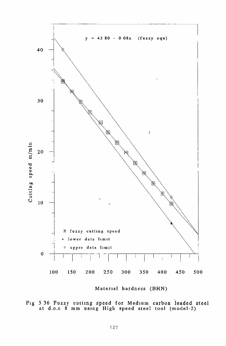
Cut
ting
sp
eed
m/m
in
100 150 2 0 0 2 5 0 3 0 0 350 4 0 0 45 0 500
M a t e r i a l h a r d n e s s ( B H N )
Fi g 5 36 F u z z y c u t t i n g s p e e d f o r M e d i u m c a r b o n l e a d e d s t e e lat d . o . c 8 mm u s i n g H i g h s p e e d s t e e l t o o l ( m o d e l - 2 )
1 27

Cut
ting
sp
eed
m/m
in
100 150 2 0 0 2 5 0 30 0 350 4 0 0 4 5 0 50 0
M a t e r i a l h a r d n e s s ( B H N )1
F i g 5 .37 F u z z y c u t t i n g s p e e d f o r M e d i u m c a r b o n l e a d e d s t e e la t d o c 1 m m u s i n g C a r b i d e t o o l - c o a t e d ( m o d e l - 2 )
1 28

Cut
ting
sp
eed
m/m
in
100 150 2 0 0 2 5 0 30 0 350 4 0 0 4 5 0 50 0
M a t e r i a l h a r d n e s s ( B H N )
F i g 5 .38 F u z z y c u t t i n g s p e e d f o r M e d i u m c a r b o n l e a d e d s t e e lat d o c 4 m m u s i n g a C a r b i d e t o o l - c o a t e d ( m o d e l - 2 )

Cut
ting
sp
eed
m/m
in
100 150 2 0 0 2 5 0 30 0 35 0 4 0 0 4 5 0 500
M a t e r i a l h a r d n e s s ( B H N )
F i g 5 .39 F u z z y c u t t i n g s p e e d f o r M e d i u m c a r b o n l e a d e d s t e e lat d . o . c 8 mm u s i n g a C a r b i d e t o o l - c o a t e d ( m o d e l - 2 )

190
180
170
160
150
140
130
120
110
100
90
80
70
60
g 5d . o
2 0 5 2 2 - 0 2 8 x ( f u z z y e q u )
f u z z y c u t t i n g s p e e d
l o w e r d a t a b a n d
0 u p p e r d a t a b a n d
0 150 2 0 0 2 5 0 3 0 0 350 4 0 0 45 0 50
M a t e r i a l h a r d n e s s ( B H N )
F u z z y c u t t i n g s p e e d f o r M e d i u m c a r b o n l e a d e d s. m m u s i n g a C a r b i d e t o o l - u n c o a t e d b r a z e d ( mo d
131
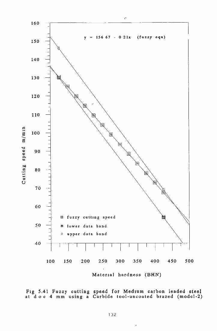
Cut
ting
sp
eed
m/m
inr
100 150 2 0 0 2 5 0 3 0 0 350 4 0 0 4 5 0 5 00
M a t e r i a l h a r d n e s s ( B H N )
Fi g 5.41 F u z z y c u t t i n g s p e e d f o r M e d i u m c a r b o n l e a d e d s t e e la t d o c 4 mm u s i n g a C a r b i d e t o o l - u n c o a t e d b r a z e d ( m o d e l - 2 )
1 32
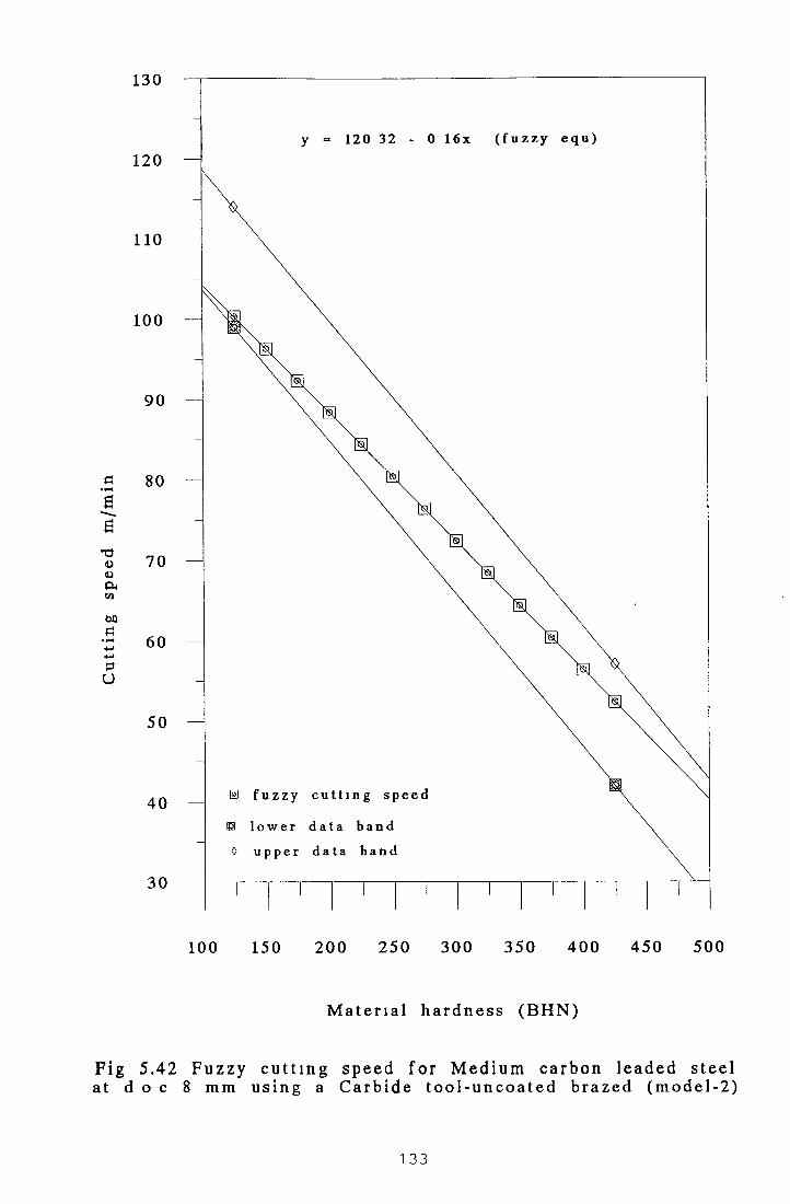
130
120
110
100
90
80
70
60
50
40
30
5.4
Cut
ting
sp
eed
m/m
in260
100 150 2 0 0 2 5 0 3 0 0 35 0 4 0 0 4 5 0 500
M a t e r i a l h a r d n e s s ( B H N )
Fi g 5.43 F u z z y c u t t i n g s p e e d f o r M e d i u m c a r b o n l e a d e d s t e e lat d o c 1 m m u s i n g a C a r b i d e t o o l - u n c o a t e d i n d e x a b l e
( m o d e l - 2 )
1 34

Cut
ting
sp
eed
m/m
in
100 150 2 0 0 2 5 0 30 0 350 4 0 0 4 5 0 50 0
M a t e r i a l h a r d n e s s ( B H N )
F i g 5. 44 F u z z y c u t t i n g s p e e d f o r M e d i u m c a r b o n l e a d e d s t e e lat d o c 4 mm u s i n g a C a r b i d e t o o l - u n c o a t e d i n d e x a b l e
( m o d e l - 2 )
1 35

160
150
140
130
120
110
100
90
80
70
60
50
5 .45a t d
r
y - 155 8 2 - 0 2 0 x ( f u z z y e q u )
f u z z y c u t t i n g s p e e d
l o w e r d a t a b a n d
0 u p p e r d a t a b a n d
0 150 2 0 0 2 5 0 30 0 350 4 0 0 450 50
M a t e r i a l h a r d n e s s ( B H N )
u z z y c u t t i n g s p e e d f o r M e d i u m c a r b o n l e a d e d st8 mm u s i n g a C a r b i d e t o o l - u n c o a t e d i n d e x a b l e
( m o d e l - 2 )
1 36

CHAPTER 6
6.1 Fuzzy Logic Simulation Program for Machining Data Selection.
A computer program has been developed in QBASIC to facilitate automatic
selection of cutting speed for known cutting tool, surface finish and hardness o f
material to be cut. There are two main modules in the program.
(i) DISPLAYMENU is for the programmer to incorporate data for new material.
(ii) USERMENU is for the operator to use for data selection.
When the DISPLAYMENU is activated, it allows the user to input a new material
name, tool name, and depth o f cut. It also takes the material hardness ranges and
cutting speed ranges. From these input data the membership function for each fuzzy
set for hardness and speed are calculated and descritized universe o f metal hardness
and cutting speed are created in an array form. From these two descritized universe
o f metal hardness and cutting speed, a fuzzy relational table has been established.
An average constant speed table has been created from this fuzzy relation table and
stored in an array form. The actual cutting speed has been calculated for each
hardness value, based on a known cutting tool and depth o f cut. Using these
hardness values and cutting speeds, equations have been established employing least
square curve fitting method and the relevant parameters have been stored in a
random access file called “Tool DAT”.
When the USERMENU is activated it offers the operator two types o f material that
are available on the system for machining data selection. It allows the operator to
input metal hardness, his choice o f tool and the required surface finish. Appropriate
program module takes this data and starts searching for the corresponding equation
in the file Tool.DAT and calculates the cutting speed and also displays the cutting
conditions on the screen for the operator. This USERMENU has been designed with
a do-loop manner so that the operator can obtain the cutting conditions as many
times as required for different input data. As two materials, four different types of
tools and three different depths o f cut were used for this research, there are 24
different records stored in the file Tool.DAT. This software has been designed in a
1 37

modular fashion to perform different tasks independently A full program listing can
be seen in Appendix while a flow chart is given at Section 6 2
Using this software, calculations have been earned out to obtain the cutting
conditions in terms o f cutting speed and depth o f cut for different types o f cutting
tool matenals This software also determines the relationship between the hardness
- value o f the matenal and the cutting speed and stores them m a random access file
Therefore, it facilitates the operator to determine the cutting conditions for any
hardness value for two matenals (1) medium carbon-leaded steel and (11)
freemachming carbon wrought steel The results obtained by using this software are
shown m the tables and figures m chapter five

6.2 Flow Chart of the Fuzzy Software
PerformIMita
Uted?taRoutine
PerformGethanJRottine
PerfonnGetodRoutine
PerfonnGetrcgfnush
Routine
PerformGctfile
1 39
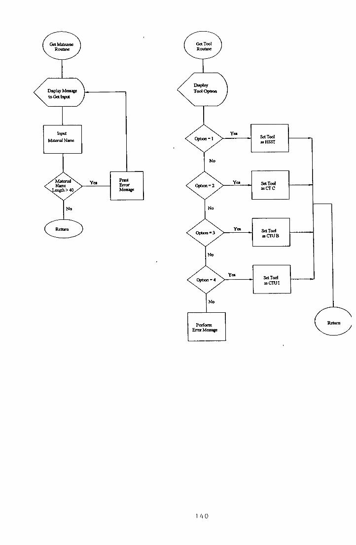
Get Mainarne Routine
Get Tool Routine
1 AO

Hard Spbt Roctme

baleniate M cabcnkip Value for Fuzzy Set V S (v a y toft)
baleniate M cabcnhp Value Tor Fuzzy Set SO (n ft)
Ideatale M an b ad u p Value Tar F vzq Set M E D (medium)
ik o h t c Membership V ah e for Fuzzy Se tM E D H (medium high)
ilc u h te Membership Value for Fuzzy Set HA (hard)
Calculate Mem beniup Value for Fuzzy
Set V H (vo y bard)
1 42

143
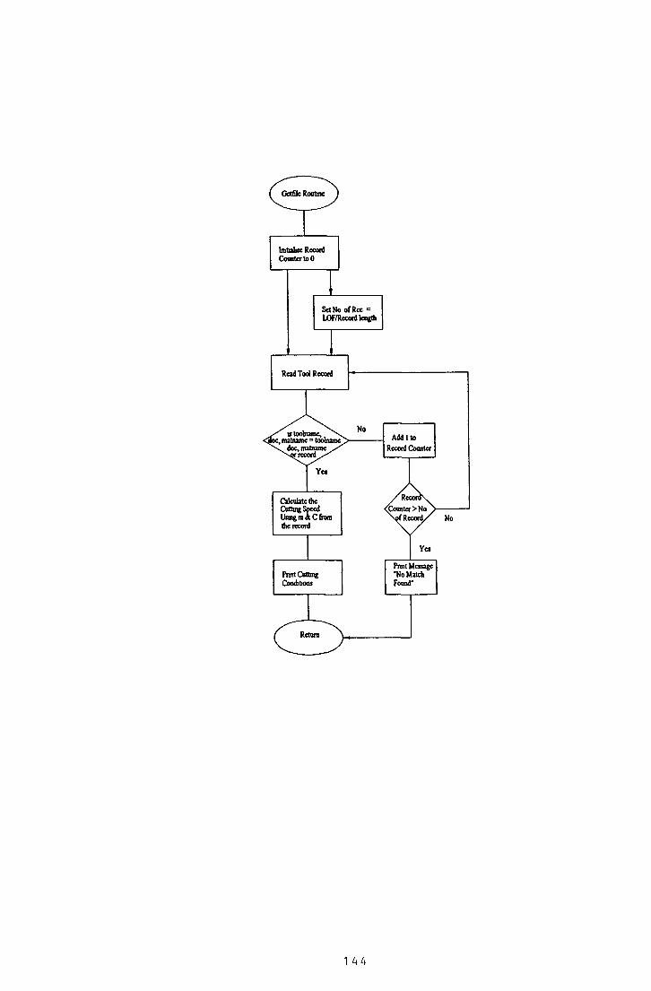
ProitCut
ComfatKMtmgu
Prmt M enage 'N o M atch Foand"

CHAPTER 7 CONCLUSIONS AND RECOMMENDATIONS
7.1 Conclusion.
A Fuzzy logic based model was employed for selecting cutting conditions in
machining operations Two materials, medium carbon leaded steel and
freemachinmg carbon wrought steel were used at three different depths o f cut (1mm,
4mm and 8mm) for theoretical calculations based on experimental data Four
different types o f cutting tools were used for theoretical calculations and they were l)
High Speed Steel Tool, 11) Carbide tool-uncoated, in) carbide tool-uncoated brazed
and i v ) carbide tool-uncoated indexable
Two fuzzy models were developed for these calculations In Model -1 fuzzy
sets were overlapped at 50% and in model-2 fuzzy sets were overlapped at
33%
Computer software was developed to implement the fuzzy logic principles
and to produce the cutting conditions for machining operations
automatically
Fuzzy model 1 produces theoretical results which fits better with the
experimental data than the results obtained using model 2
In both models the fuzzy cutting speeds in terms o f different cutting
conditions, lie within the lower and upper limits o f the experimental data
bands
Equations have been established between the hardness values and fuzzy
cutting speed values
Results show that the fuzzy logic method can be used satisfactorily to present
the cutting conditions in a compressed way
It has been assumed that the cutting speed obtained using fuzzy logic
principles would produce better cutting results in terms of either better
1 45
surface finish, or lower cutting force or longer tool life Experimental work
will be necessary to be earned out in order to venfy this assumptions
However such expenmental works were beyond the scope of the present
study
7.2 Recommendations for Further Work
In this study only two matenals were used Expenmental data for other
matenals could also be represented by the fuzzy logic model
Expenmental works should be earned out to venfy the predicted results
obtained by employing the fuzzy logic models
Expenmental works should be earned out to venfy the fuzzy logic
predictions m terms o f satisfactory surface quality
In this study, the hardness o f the workpiece has been used as the only
matenal property Other matenal properties which have significant effect on
the machining quality o f the workpiece matenal, for example matenal
toughness (ductility/bnttleness) should be considered
A fuzzy logic model can be developed based on a minimum of two such
mechanical properties (hardness and ductility) and used as a predictive tool
for machining conditions for new matenals for which there is no
expenmental data currently existing

REFERENCES
1 Zadeh, L A , “Fuzzy Sets” , Information & Control, Vol 8, pp 338 - 353, 1965
2 Sukvittayawong, Saw ai, “Identification o f chip form in turning process”, JSME Int J.
Series 3 Vibration, Control Engineering, Engineering for Industry, Vol 34, n4, pp
553-560, 1991
3 Lewis, Mark, “Fuzzy Logic a new tool for the control engineer’s toolbox”, Power
transmission design, Vol 36, n9, pp 29-32, 1994
4 Wang, Yongm ei, Birdwell, J D ouglas, “Nontiness PID-type controller utilising fuzzy
logic”, Proc o f the IEEE/IF AC Joint Symposium on Computer Aided Control System
Design, pp 89-94, 1994 1
5 Wang, W , Lie, W , Chen, Y , “Fuzzy-computing method for rotation-invariant image
tracking”, Proc of the 1994 1st IEEE Inter Conference on Image Processing, Part 1
(of 3), Vol l , p p 540-5444,1994
6 DeCorte, C , Holland, J Martin, A , “Security robots A dual-use technology”,
Defence Electronics, Vol 26, n8, pp 19-20, 1994
7 Dhawan, R K Davis, P , Naik, R , “Expert systems/fuzzy logic select core geometry
for HF power transformers part lifundamentals, power conversion + intelligent motion
The Fusion o f Power & Motion Technology & Applications, Vol 21, n4, pp 4, 1995
8 Xiong, H , and Holdtich, S A , “Investigation into the application o f fuzzy logic to well
stimulation treatment design”, Proc o f the Premian Basion Oil + Gas Recovery
Conference, Publ by Society o f Petroleum Engineers (SPE), Richardson, TX, USA,
pp 157-168, 1994
1 4 7

9 Gondo, H , Kikuchi, T , Furukawa, T , Motoyaochiki, Y , “Development o f stnp
crown control system in hot strip mill”, Proc o f the 20th Inter Conf on Industrial
Electronics, Control and Instrumentation, Voi 3, pp 1999-2004, 1994
10 Wong, B K , Elliot, M P , Rapley, C W , “Automatic casting surface defect recognition
and classification”, Machine Vision Application in Industrial Inspection [1], Vol 2423,
pp 292-300, 1995
11 Uragami, M , et al, “Fuzzy robot controls”, J Cybernetics, Vol 6, 1976, pp 39-64
12 Goguen, J , “On fuzzy robot planning”, in fuzzy sets and application to cognitive
decision processes, (cds) by Zadeh, 2 et al, 1977 pp 429-447
13 Hirota, K et al, “Robot Control based on membership and vagueness” in Approximate
Reasoning in Expert Systems, (eds ) by Gypta, M M , et al, 1985, pp 621-635
14 Scharf, E M , Mandic, N J , and Mamdani, E H , “A self organising algorithm for the
control o f a robot arm”, Proc 23 rd ISMM Int Symp Mini and Microcomputers and
their applications, pp 843, 1983
15 Tanscheit, R and Scharf, E M , “Experiments with the use o f a rule-based self-
organising controller or robotics application”, Fuzzy Sets and Systems, Vol 26, pp
195 -214, 1988
16 Kouatli, I and Jones, B , “An improved design procedure for fuzzy control systems”,
Int J Mach Tools and M anufact, Vol 31, No 1, 1991, pp 107-122
17 Saradis, G N , “Intelligent Robotic Control”, IEEE Trans on AC, Vol AC-28, No 5
1983, pp 547-557
18 , “Foundations o f the theory o f intelligent controls”, IEEE workshop on
intelligent control, USA 1986 pp 23-28
1 48

Saradis, G N and Graham, J H , “Linguistic decision seemata for intelligent robots”,
Automatica vol 20, no 1, 1984, pp 121-126
Ray K S , et al “Structure o f an intelligent fuzzy logic controller and its behaviour”, in
Approximate Reasoning in Expert Systems, (eds) by Gupta, M M , et al, 1985, pp 593
-619
Chen Y Y and Tsao, T C , “A description o f the dynamical behaviour o f fuzzy
systems”, IEEE Trans On Sys t , Man, and Cybern , Vol 19, no 4, 1989, pp 745 -
755
Togai, M and Watanabe, H , “Expert systems on a chip An engine for real-time
approximate reasoning”, IEEE Expert, Fall 1986 pp 55 - 62
Yamakawa, T and Miki, K , “The current mode fuzzy logic integrated circuits
fabricated by the standard CMOS process”, IEEE Trans On computer, Vol C-35,
No 2, 1986, pp 161 - 167
Eshera, M A and Barash, S C , “Parallel rule based fuzzy inference on mesh-connected
systolic arrays”, IEEE Expert, Winter, 1989, pp 27 - 35
Lim, M H and Takefuji, Y , “Implementing fuzzy rule-based system on silicon chips”,
IEEE Expert, Feb 1990, p 31 - 45
Waller, L , “Fuzzy logic It’s comprehensible, it’s practical . . . and it’s
commercial”, Electronics March, 1989
Williams, T , “Fuzzy logic simplifies complete control problems” Computer design,
March 1991, pp 90 - 102

Quail, S , and Adnan,S , “State o f the art in household appliance using fuzzy logic”,
Proc o f the second international workshop - industrial fuzzy control o f intelligent
systems, IEEE Press, College Station, TX, pp 204 - 213, 1992
Berardims, L , “Building better models with fuzzy logic”, Machine Design, Vol 64,
No 11, 1992
Buckley, T , “Forecast for a fuzzy future”, marketing computers, pub date Dec 1990
Self, K , “Designing with fuzzy logic”, IEEE Spectrum, Vol 27, No 11, 1990
Sibigtroth, J M , “Creating fuzzy micros”, Embedded systems programming, Vol 4,
No 12, 1991
Williams, T , “Fuzzy logic is anything but fuzzy”, Computer Design, Pub Date April,
1992
Wong, F S , et al, “Fuzzy neural systems for stock selection”, Financial Analysis
Journal, Vol 48, Vol 1, 1992
Rogers, M , an d Hoshai, Y , “The future looks fuzzy”, Newsweek, Vol 115, No 22,
1990
Reid, T R , “The future o f electronics looks fuzzy”, Japanese firms selling computer
logic products, The Washington Post, Financial Sectm, p H -l, 1990
Anonymous, NEC and omron to make fuzzy microcomputer, Newsbytes News
Network, Pub date 08/05/91
Anonymous, “Fuzzy logic is clearly a trend”, Korea high tech review, Vol 5, No 11,
1990
Anonymous, “Domotechmca '91 emphasises high-tech, environmental protection”,
Journal o f the electronics industry, Vol 38, No 4

40. Berardinis, L., “Strong bonds link neural and fuzzy computing,” Machine design, Vol.
64, No. 15, 1992.
41. Hirota, K., “Fuzzy concept very clear in Japan”, Asahi Evening News, p. 35, 1991.
42. Mitsuada, H., “Fuzzy logic moving smoothly into the home”, The Japanese Economic
Journal, Pub. Date 06/16/90.
43. Anonymous, Sharp introduces bubble action washing machine, Japan Consumer
Electronics Scan, Pub. Date 07/08/91.
44. Hulme, D., “Japan stants fuzzy logic II”, Machine design, Vol. 64, No. 18, 1992.
45. Jurgen, R.K., “Consumer electronics”, IEEE spectrum, Vol. 28, No. 1, 1991.
46. Remich, Jr. and Norman, C., “Fuzzy logic appliances”, Appliance manufacturer, Vol.
39, No. 4, 1991.
47. Slutsker, G., “Why fuzzy logic is good business”, Forbes, Vol. 147, No. 10, 1991.
48. Remich, Jr. and Norman, C., “Fuzzy logic now across most appliance lines”, Appliance
manufacture, Vol. 40, No. 4, 1992.
49. Pargh, A., “Vacuum cleaners getting smarters”, Design news, Vol. 48, No. 7, 1992.
50. Inaba, M., Matsushita 'Fuzzy logic’ M wave. HFD, pp. 252, Pub. Date 10/08/90.
51. M.A. Fuzzy logic refrigerator. Appliance manufacturer, Vol. 40, No. 2, 1992.
52. Babyak, R.J., “Designing the future”, Appliance manufacturer, Vol. 40, No. 7, 1992.
151

53. Johnson, R.C., “Fuzzy logic escapes the laboratory”, Electronic Engineering Times, p.
16, Pub. Date 08/02/90.
54. Weinberg, B.; Breggear, M., Fuzzy set database search methodology for the modelling
o f adverse animal reactions in drug research”, 13 th Annual International Conference of
the IEEE Engineering in Medicine and Biology Society, pp. 1347 - 1348, 1991.
55. Meier, R. et al (1992). “Fuzzy logic control o f blood pressure during anaesthesia”,
IEEE control syst., pp 12 - 17, December, 1992.
56. Tsutsui, Toshinori, and Arita, Seizaburou., “Fuzzy logic control o f blood pressure
through enflurane anaesthesia” , Journal o f Clinical Monitoring, vol, 10, n 2, p.p. 110 -
117, 1994.
57. Shaw, M.C., and Nakayama, M., “Machining High Strength Materials”, Annals o f the
CIRP, VOL.15, p.p. 45 - 59, 1967.
58. Taraman, K., “Multi Machining Output-Multi Independent Variable Turning Research
by Response Surface Methodology”, Int.J. o f Prod. Res., Vol. 12(2), p.p. 233-245,
1974.
59. Chang and Fuh, “Study o f cutting performance in turning plain carbon steel using tin-
coated, ticn-coated, and uncoated cemented carbide tools with chamfered main cutting
edge, “Materials and Manufacturing Processes, vol. 10, n3, p.p. 453-472, 1995.
60. Lin, J.I., Bhattacharyya, D., Lane, C., “Machinability o f a silicon carbide reinforced
aluminium metal matrix composite”, 10th Int. Conf on wear o f Materials BOSTON,
USA
Part 2., vol 181 - 183 n 2, p.p. 883 - 888, 1995.
61. Wilson, M. and EL-Baradie, M., “Machining High Strength Materials : Cobalt-Base
Alloys, Proc. 23rd Int. Machine Tool Design and Research (MATADOR) Conf.,
VMIST, Manchester, p.p. 171 - 182, 1982.
1 52
62. Huet, J.F. and Kramer, B .M., “The Wear o f Ceramic Cutting Tools”, Proc. x
NAMRC, SME, p.p. 297 - 304, 1982.
63. Wright, P. K. and Chow, J. G., “Deformation Characteristics o f Nickel Alloys during
Machining”, J. o f Engineering Materials and Technology, Transaction of the ASME,
vol. 104, p.p. 85-93, 1982
64. Abrao, A. M., Aspinwall, D.K., Wise, M.L.H., “Tool life and workpiece surface
integrity evaluations when machining hardened AISI H I3 and AISIE52100 steels with
conventional ceramic and PCBN tool materials”, Proc. NAMRC XXIII Conf.
Houghton, MI, USA, p.p. 9, 1995.
65. Dam, H., Quist, P., Schreiber, M.P., “Productivity, surface quality and tolerances in
ultrasonic machining o f ceramics “, J. o f Materials Processing Technology, vol 51 n 1 -
4, p.p. 358 -368, 1995.
66. Komanduri, R and Schroeder, R. A., “On shear Instability in Machining Nickel-Based
Superalloys”, J. Engineering for Industry, Transaction o f ASME, vol. 108, p.p. 93 -
100, 1986.
67. Sadat, A.B., “Surface Characteristics ofMachined Inconel - 718 Nickel-Base
Superalloy using National and Controlled Contact Length Tools”, International Journal
o f Machine Tools Manufacture, vol. 27(3), p.p. 333-342, 1987.
68. Dontamsetti, S.K. and Fischer, G.W., “Factors Affecting Surface Roughness in Finish
Turning o f Grey Cast Iron”, Advanced Materials and Manufacturing Processes, Vol.
3(4), p.p. 689 -725, 1988.
69. Lim, G. H , “Tool-Wear Monitoring in Machine Turning”, J. of Materials Processing
Technology, Vol. 51, n 1 - 4, p.p. 25 - 36, 1996.
1 53

70 Mital, A and Mehta, M , “Surface Finish Prediction Models for Fine Turning”, Int J
o f Prod Res , vol 26(12), p p 1861-1876,1988
71 Karmakar, A , “Factors Influencing Surface Finish During Fine Turning”, Proc 4th All
India Machine Tool Design and Research Conf INDIA, p p 123 - 128, 1970
72 Chandiramani, K L , and Cook, N H , “Investigations on the Nature o f Surface Finigh
and its Variation with Cutting Speed”, J o f Engineering for Industiy, 86 - 87, series
B, 134 - 140, 1964
73 Yaguchi, H , “Effect o f Cold Working on the Machinability o f low-carbon leaded free-
machming steel”, 13th NAMRC, North American Manufacturing Research Conference
Proceedings, p p 245 - 251, 1985
74 Ohatani, T and Yokogawa, H , “The Effects o f Workpiece Hardness on Tool Wear
Characteristics - Machining o f Cold Work Tool Steel with CBN, Ceramic and Carbide
Tool”, Bull Japan Soc ofP rec E ngg ,vo l 22 (3), p p 229-231 ,1988
75 Akhtar, S , Redford, A. H , Mills, B , “Short-Time Method for Assessment o f the
Machinability o f Low Carbon Free Machining Steels”, Int Journal o f Machine Tool
Design and Research, vol 16, n 1, p p 7 1 - 75 , 1976
76 Enomoto, S , Kato, M , Miyazawa, S , and Ono, T , “Characteristics o f Tool Life of
CBN Cutting Tool in Turing Chromium-Molybdenum Steels o f Various Hardness”,
Bull Japan Soc ofPrec Engg , vol 21 (3), p p 209 - 210, 1987
77 Bandyopadhyay, B P and Teo, E H , “Application o f Factorial Design o f Experiment
in High Speed Turning “, Proc Manufacturing International ‘90, Part 4 Advance in
Materials and Automation, Atlanta, GA, USA, ASME publication, p p 3 - 8 , 1990
78 EL-Baradie, M A , “Surface Roughness model for Turning Grey Cast Iron
(154BHN)”, Proc, Instn Mech Engrs „ Vol 207, IMechE, p p 43 - 54, 1993
154

79 Armarego, E J A and BROWN, R H , “The machining o f metals”, Prentice Hall, Inc ,
New Jersey, 1976
80 Boulgar, F W , “Machining - Theory and Practice”, paper 69, Cleveland, Ohio, 1950
81 Boston, “Machmabihty o f Ordnance Steels”, paper no sp -123 Soc o f Automative
Engineers 1958
82 Eamst, H , “Physics o f Metal Cutting”, ASM, Cleveland, Ohio, 1938
83 Reen, O W , “Modem Developments in Power Metallurgy”, MPIF Publishers,
Pnncetown, NJ, vol 10, p p 431 -451,1977
84 Trent, E M , Metal Cutting, Butterworths, London, 1977
85 Sandvik, Modem Metal Cutting, Sandvik Coromant, Sweden, 1994
86 Cherry, J , “Practical Investigation in Metal Cutting”, The Production Engineer, vol,
81,1962
87 Field, M , “Relation o f Microstructure to the Machmabihty o f Wrought Steel and Cast
Irons”, Int Production Engineering Research C onf, ASME 1963
88 Howe, R , “Productivity/Machmabihty o f Space-Age and Conventional Materials”
ASTME, 1968
89 Kronenberg, M , Machining Science and Application, Pergamon Press, 1966
90 Smith, G T , “Surface Integrity Aspects o f Machmabihty Testing o f Fe-Cu-C powder
metallurgy components”, Powder Metallurgy, vol 33 (2), p p 157 - 164, 1990
1 55

91 Boothroyd, G / ’Fundamentals o f Metal Machining and Machine Tools”, McGraw-Hill
Book Company, 1975
92 Rao, S B , “Tool Wear Monitoring Through the Dynamics o f Stable Turning”, J of
Engineering for Industry, Transaction o f ASME, Vol 108(3), p p 183 - 190,1986
93 Sandvik, Coromant, Modem Metal Cutting - A practical handbook 1994
94 Bowden, F P , and Tabor, D , “Faction and Lubrication o f Solids”, Oxford
University Press, London, 1954
95 Oberle, T L “Properties Influencing Wear o f Metals”, Journal o f Metals vol 3, p p
438,1951
96 Bowden, F P and Tabor, D , The Faction and Lubrication o f Solids, part II, Oxford
Clarendon Press, 1964
97 Nicolls, M O , “The measurement o f Surface Finish”, De Beers Technical Service
Centre, UK
98 Boothroyd, G , “Fundamental o f Metal Machining and Machine Tools”, McGraw -
Hill Book Company, 1985
99 Metcut Research Associates Inc , “Machining Data Handbook”, 3rd Edn, vols 1 and 2,
Cincinnati (1980)
1 56

APPENDIX
Programme Listing

Fuzzy.bas
Program Name
Purpose
Author
Context
Language used
System requirements
Date Completed
Version
FUZZY
Provides a Fuzzy Logic based approach to selecting machining parameters
Ms Kashmen Hashmi
Submitted as part o f thesis for the award M Sc in Computer Applications
QBASIC
IBM PC or equivalent running M S-DOS
20 March 1997
1 00
Page 1

u
Fuzzy bas
' Subroutines used are declared below
DECLARE SUB CHANGEDATA 0 DECLARE SUB TESTING 0 DECLARE SUB ERRORMESSAGE 1 ()DECLARE SUB ERRORMESSAGE2 ()DECLARE SUB OPMENU 0 DECLARE SUB GETTOOL 0 DECLARE SUB GETREQFINISH 0 DECLARE SUB MAIN MENU 0 DECLARE SUB ERRORMESSAGE3 0 DECLARE SUB GETMATNAME 0 DECLARE SUB DISPLAYMENU 0 DECLARE SUB USERMENU 0 DECLARE SUB GETNEWDATA 0 DECLARE SUB HARDSPLIT ()DECLARE SUB SPEEDSPLIT 0 DECLARE SUB HARDTABLE 0 DECLARE SUB SPEEDTABLE 0 DECLARE SUB TRUTHTABLE 0 DECLARE SUB CONSTABLE 0 DECLARE SUB FINALCALC 0 DECLARE SUB MAKEQUA 0 DECLARE SUB USEDATA 0 DECLARE SUB GETNAME 0 DECLARE SUB GETHARD ()DECLARE SUB GETFILE 0 DECLARE SUB ERRORMESSAGE 0
’ End of declaration of all the subroutines
1 Array used
AS SINGLE AS SINGLE AS SINGLE AS SINGLE AS SINGLE AS SINGLE AS SINGLE
DIM SHARED DIM SHARED DIM SHARED DIM SHARED DIM SHARED DIM SHARED DIM SHARED
hd(20)SP(10)HARD(5, 20) SPEED(5, 10) FINALTABLE(20, 10) CONSPEED(20) ACULSPEED(20)
End of reserving all the arrays for future use
Page 2

Fuzzy bas
Declaration of shared variables
COMMON SHARED choice AS INTEGERCOMMON SHARED lowrange AS INTEGERCOMMON SHARED highrange AS INTEGERCOMMON SHARED highspeed AS INTEGERCOMMON SHARED lowspeed AS INTEGERCOMMON SHARED doc AS INTEGERCOMMON SHARED result AS SINGLECOMMON SHARED userchoice AS INTEGERCOMMON SHARED toolname AS STRING* 40COMMON SHARED matname AS STRING* 40COMMON SHARED finish AS STRING* 15COMMON SHARED hardness AS SINGLECOMMON SHARED cutspeed AS SINGLE
End of declaration of all common shared variables
Define record layout
TYPE toolrecmname AS STRING * 40tname AS STRING * 40doct AS INTEGERhardlow AS INTEGERequam AS SINGLEequac AS SINGLE
END TYPECOMMON SHARED cd AS toolrec
*****************************************************
MAIN PROGRAM STARTS HERE
OPEN "c tool dat" FOR RANDOM AS #1 LEN = 94
CALL DISPLAYMENU This menu is for programer's use only
CALL USERMENU This menu is for operator only'to find the cutting conditions 'of a metal
CLOSE #1
END 'End of main program
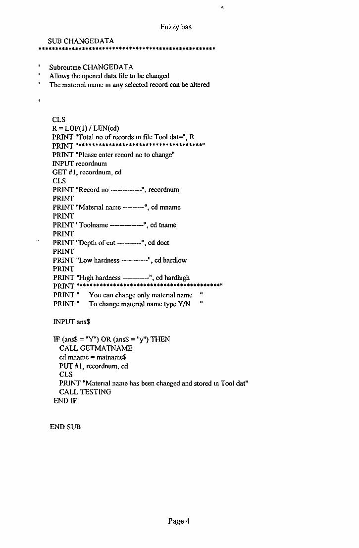
' Subroutine CHANGEDATA' Allows the opened data file to be changed1 The material name in any selected record can be altered
Fuzzy bas
SUB CHANG ED ATA* * * * * * * * * * * * * * * * * * * * * * * * * * * * * * * * * * * * * * * * * * * * * * * * * * * * *
CLSR = L0F(1) / LEN(cd)PRINT "Total no of records in file Tool dat=", R PRINT "*************************************"PRINT "Please enter record no to change"INPUT recordnum GET #1, recordnum, cd CLSPRINT "Record no------------ ", recordnumPRINTPRINT "Material name---------", cd mnamePRINTPRINT "Toolname------------- ", cd tnamePRINTPRINT "Depth of cu t----------", cd doctPRINTPRINT "Low hardness----------", cd hardlowPRINTPRINT "High hardness--------- ", cd hardhighPRINT "******************************************"PRINT " You can change only material name "PRINT " To change material name type Y/N "
INPUT ans$
IF (ans$ = "Y") OR (ans$ = "y") THEN CALL GETMATNAME cd mname = matnameS PUT #1, recordnum, cd CLSPRINT "Material name has been changed and stored in Tool dat" CALL TESTING
END IF
END SUB
Page 4

Fuzzy bas
Subroutine CONSTABLE
SUB CONSTABLE*******************************************************
Creates the average speed values shown in Table 5 9 in Chap 5
CLSFOR i = 0 TO 20
LET sum = 0 LET suml = 0 FORj = 0 TO 10
sum = sum + FINALTABLE(i, j) * j sum l = sum l + FINALTABLE(i, j)
NE X T j
result = sum / sum 1 conspeed(i) = result
NEXT i
END SUB
SUB DISPLAYMENUi * * * * * * * * * * * * * * * * * * * * * * * * * * * * * * * * * * * * * * * * * * * * * * * * * * * * *
' Subroutine DISPLAYMENU1 Displays a menu for use by the system administrator only 1
I
CLS
DOMAIN MENU SELECT CASE choice
CASE 1 GETNEWDATA
CASE 2 CHANGEDATA
CASE 3PRINT "Thankyou for using fuzzy expert system " PRINT "Goodbye "PRINT
CASE ELSE ERRORMESSAGE
END SELECT LOOP UNTIL (choice = 3)
END SUB
Page 5

Fuzzy bas
Subroutine ERRORMESSAGEUsed to display error messeages for DISPLAYMENU
SUB ERRORMESSAGE**********************************************************
CLSPRINT "You must enter 1 or 2 or 3 only "PRINTPRINT "Please try again "PRINT
END SUB
SUB ERRORMESSAGE 1 * * * * * * * * * * * * * * * * * * * * * * * * * * * * * * * * * * * * * * * * * * * * * * * * * * * * * * *
Subroutine ERRORMESSAGE 1Used to display error messages for GETTOOL
CLS
PRINTPRINT "You must enter 1 or 2 or 3 or 4 only" PRINT "please try again "PRINT
END SUB
SUB ERRORMESSAGE2 * * * * * * * * * * * * * * * * * * * * * * * * * * * * * * * * * * * * * * * * * * * * * * * * * * * * * *
Subroutine ERRORMESSAGE2Used to display error messages for GETREQFINISH
CLSPRINT "You have pressed the wrong key"PRINTPRINT "Please try again"
END SUB
Page 6

Fuzzy bas
Subroutine ERRORMESSAGE3Used to display error messages for GETHARD
SUB ERR0RMESSAGE3*****************************************************
CLSPRINTPRINT "You have entered wrong hardness for ", matnameS PRINTPRINT "Please try again "PRINT
END SUB
SUB FINALCALC ***************************************************
Subroutine FINALCALC Calculates the final cutting speeds
diff = highspeed - lowspeed CLSPRINT "Speed difference betwee high and low speed is as follows "PRINT"*********************************************************" PRINTPRINT "Speed difference^ ", diffPRINTPRINTCALL TESTING
FOR 1 = 0 TO 20 ACULSPEED(i) = conspeed(i) / 10 * diff + lowspeed
NEXT i
END SUB
Page 7

Fuzzy bas
SUB GETFILE
' Subroutine GETFILE' Opens data file and searches for corresponding record ' and performs calculations and displays cutting parameters ' when match is found
CLSP R IN T "**********************************♦*********************" PRINTPRINT "Material name requisted by the operator **", matname$PRINTPRINT "Hardness o f the material *****************"5 hardness PRINTPRINT "Toolname requested by the operator * * * * * * * * t toolnameS PRINTPRINT "Surface finish requested for this operation**", finish$P R IN T "********************************************************" PRINT PRINT
CALL TESTING R = LO F(l) / LEN(cd) match = 0FOR recnum - 1 TO R
GET #1, recnum, cd IF (cd mname = matname$)AND (cd tname - toolnameS)AND (cd doct = doc)THENcutspeed = (cd equam * hardness) + cd equac match - match + 1 CLS PRINTPRINT "Cutting parameters for material ", cd mnamePRINTPR IN T " are as follows "PRINTPRINT "For material hardness(BHN)-------------- ", hardnessPRINTPRINT "Cutting speed(m/min)--------------------- ", cutspeedPRINTPRINT "Depth o f cut(mm)-------------------------- ", cd doctPRINTPRINT "Cutting tool is--------------------------- ", cd tnamePRINTCALL TESTING
END IF NEXT recnum
'Holds the screen 'Total number o f records
'Get the next record
Page 8

Fuzzy bas
IF match = 0 THEN CLSPRINT " Matching data not found " PRINT" *********************** «PRINTPRINTCALL TESTING
END IF
END SUB
SUB GETHARDi * * * * * * * * * * * * * * * * * * * * * * * * * * * * * * * * * * * * * * * * * * * * * * * * * *, J
' Subroutine GETHARD ' accepts material hardness from user
entrhardCLSPRINT "Material hardness (BHN) for MEDIUM CARBON LEADED should PRINT "be in the range between 125-425 "PRINTPRINT "Material hardness (BHN) for FREE MACHINING CARBON WROUGHT " PRINTPRINT "be m the range between 225—425 "PRINTPRINT "Now enter your required hardness "PRINTINPUT hardnessIF (userchoice = 1) AND ((hardness < 125) OR (hardness > 425)) THEN
CLSCALL ERRORMESSAGE3 CALL TESTING GOTO entrhard
END IFIF (userchoice = 2) AND ((hardness < 225) OR (hardness > 425)) THEN
CLSCALL ERRORMES SAGE3 CALL TESTING GOTO entrhard
END IF END SUB
Page 9

Fuzzy bas
SUB GETMATNAME
' Subroutine GETMATNAME ' Accepts new material name from programer
CLSmaterial
PRINT "Enter material name please"PRINTPRINT "Name should be maximum 40 characters long" PRINTINPUT matnameS IF LEN(matname$) > 40 THEN
PRINT "Material name length out of range"PRINTPRINT "Please try again "CALL TESTING GOTO material
END IF
END SUB
SUB GETNEWDATA **************************************************
Subroutine GETNEWDATADevelops Fuzzy model step by step for incorporating new data
CALL GETMATNAME CALL GETTOOL CALL GETREQFINISH CALL HARDSPLIT CALL SPEEDSPLIT CALL HARDTABLE CALL SPEEDTABLE CALL TRUTHTABLE CALL CONSTABLE CALL FINALCALC CALL MAKEQUA
END SUB
Page 10

I
Fuzzy bas
SUB GETREQFINISH
' Subroutine GETREQFINISH ' Accepts the required surface finish from user selects ' the depth of cut
CLSfinishstart
PRINT "Choose surface finish from the following options " PRINTPRINT "For smooth finish type------------------ S "PRINTPRINT "For medium finish type----------------- M "PRINTPRINT "For rough finish type -------------------R "PRINTINPUT sfimshSIF (sfimshS = "S") OR (sfimshS = "s") THEN
doc = 1finishS = "Smooth finish"
ELSEIF (sfimshS = "M") OR (sfimshS = "m") THEN doc = 4finishS = "Medium finish"
ELSEIF (sfimshS = "R") OR (sfimshS = V ) THEN doc = 8finishS = "Rough finish"
ELSECALL ERRORMESSAGE2 CALL TESTING GOTO finishstart
END IF
END SUB
Page 11

s
Fuzzy bas
SUB GETTOOLI**************************************************
' Subroutine GETTOOL1 Displays choices of tools available on the system and ' accepts user's choice
CLStoolstart
PRINT "Choose cutting tool from the following options PRINTPRINT "For High speed steel (HSS) type---------------------- 1PRINTPRINT "For Carbide tool coated (CTC) type------------------2PRINTPRINT "For Carbide tool uncoated brazed (CTUB)----------3PRINTPRINT "For Carbide tool uncoated mdexable(CTUI)---------4PRINTINPUT toolnum
IF (toolnum = 1) THEN tooInameS = "high speed steel tool"
ELSEIF (toolnum = 2) THEN toolnameS = "carbide tool coated"
ELSEIF (toolnum = 3) THEN toolnameS = "carbide tool uncoated brazed"
ELSEIF (toolnum = 4) THEN toolnameS = "carbide tool uncoated indexable"
ELSECALL ERRORMESS AGE 1 CALL TESTING GOTO toolstart
END IF
END SUB
Page 12

Fuzzy bas
SUB HARDSPLIT
' Subroutine HARDSPLIT' Accepts material hardness range from programmer and ' pertitions the hardness universe
CLSstart
midhard = 25PRINT "Insert metal hardness for the new material"PRINTPRINT "Type lowrange and then highrange in integer only" PRINT
INPUT "lowrange-', lownum INPUT "highrange-', highnum
IF lownum > highnum THEN CALL ERRORMESSAGE2 GOTO start
ELSE lowrange = lownum highrange = highnum lownum = lownum + midhard highnum = highnum - midhard
FOR 1 = 0 TO 20 hd(i) = (highnum - lownum) / 20 * i + lownum
NEXT i END IF
END SUB
SUB HARDTABLE
1
' Subroutine HARDTABLE' Calculates membership values for each fiizzy sets o f HARDNESS ' and develops descntized universe o f hardness shown in Table 1 5 2 m Chap 5I
LET a = 0 LET b = 4 LET c = 8 LET d = 12 LET e = 16 LET f = 20
Page 13

Fuzzy bas
FOR 1 = 0 TO 5 IF i = 0 THEN
FOR h = 0 TO 20 IF h <= b THEN
VS HARD(i, h) = (b - h) / (b - a)END IF
NEXTh END IF
SOFT IF i = 1 THEN FOR h = 0 TO 20
IF (h = a) OR (h < b) THEN HARD(i, h) = (h - a) / (b - a)
ELSEIF (h = b) OR (h <= c) THEN HARD(i, h) = (c - h) / (c - b)
END IF
NEXTh
END IF MED IF l = 2 THEN
FOR h = 0 TO 20 IF (h >= b) AND (h <= c) THEN
HARD(i, h) = (h - b) / (c - b)ELSEIF (h >= c) AND (h <= d) THEN
HARD(i, h) = (d - h) / (d - c)END IF
NEXTh END IF
MEDH IF i = 3 THEN FOR h = 0 TO 20
IF (h >= c) AND (h <= d) THEN HARD(i, h) = (h - c) / (d - c)
ELSEIF (h >= d) AND (h <= e) THEN HARD(i, h) = (e - h) / (e - d)
END IF NEXTh
END IF
HA IF i = 4 THENFOR h = 0 TO 20
IF (h >= d) AND (h <= e) THEN HARD(i, h) = (h - d) / (e - d)
ELSEIF (h >= e) AND (h <= f) THEN HARDO, h) = ( f - h) / ( f - e)
END IF NEXTh
END IF
Page 14
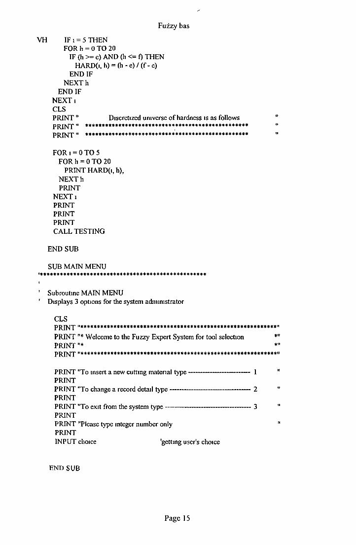
VH IF i = 5 THENFOR h = 0 TO 20
IF (h >= e) AND (h <= f) THEN HARD(i, h) = (h - e) / ( f - e)
END IF N E X T h
END IF NEXT i CLSPRINT" Discretized universe o f hardness is as follows "P R IN T " ************************************************* "PR IN T " ************************************************* "
FOR i = 0 TO 5 FOR h = 0 TO 20
PRINT HARD(i, h),N E X T h PRINT
NEXT i PRINT PRINT PRINTCALL TESTING
END SUB
SUB MAIN MENU ***************************************************
I
' Subroutine MAIN MENU ' Displays 3 options for the system administrator
CLSPRINT "***********************************************************" PRINT "* Welcome to the Fuzzy Expert System for tool selection *"PRINT "* *"PR IN T "***********************************************************"
PRINT "To insert a new cutting material ty p e------------------------------- 1 "PRINTPRINT "To change a record detail ty p e---------------------------------------- 2 "PRINTPRINT "To exit from the system ty p e------------------------------------------ 3 "PRINTPRINT "Please type integer number only 11PRINTINPUT choice 'getting user's choice
Fuzzy bas
END SUB
Page 15

Fuzzy bas
SUB MAKEQUA ***********************************************************
Subroutine MAKEQUAEstablishes the relationship between material hardness and cutting speed in the form o f an equation y=mx+c, using least square method
CLSLET n = 21 LET m = 0 LET c = 0 LET x = 0 LET y = 0 LET z = 0 LET xy = 0
FOR i = 0 TO 20 x = x + hd(i) 'Holds all the sums o f x
z = z + (hd(i) * hd(i)) 'Hold all the sums o f xA2
y = y + ACULSPEED(i) 'Holds all the sums o f y
xy = xy + (hd(i) * ACULSPEED(i)) 'Holds all the sums o f xy
NEXT ii
m = ((y / n) - (xy / x)) / ((x / n) - (z / x)) c = (y / n) - (m / n * x)
cd mname = LCASES(matnameS) cd tname = LCASE$(toolname$) cd doct = doc cd hardlow = lowrange cd hardhigh = highrange cd equam = m cd equac - c
Page 16

Fuzzy bas
PRINT " material name ********* ", cd mname PRINTPRINT " toolname ************** ", cd tname PRINTPRINT " depth of cut ********** ", cd doct PRINTPRINT " matenal lowrange ***** ", cd hardlow PRINTPRINT " material highrange **** ", cd hardhigh PRINTPRINT " m part of the equation ", cd equam PRINTPRINT " c part of the equation ", cd equac PRINTPRINT " Is it ok to save this record"PRINTPRINT " Please typeY/N"INPUT ans$IF (ans$ = "Y") OR (ans$ = "y") THEN
R = LOF(l) / 94 R = R + 1PUT # 1, R, cd 'Writes the record to Tool dat CLSPRINT "I have just written one record in the file" PRINTCALL TESTING
END IFnumber = lowrange FOR k = 0 TO 20
hd(k) = (m * number) + c number = (highrange - lowrange) / 20 + number
NEXT kPRINT "Fuzzy cutting speeds for ****", cd mnamePRINTPRINT "Hardness low range ********", cd hardlowPRINTPRINT "Hardness high range ********", cd hardhighPRINTPRINT "For depth ofcut(mm) ********", cd doctPRINTPRINT "Using cutting tool ********", cd tnamePRINTPRINT" are as follows "
FOR k = 0 TO 20 PRINT hd(k),
NEXTk PRINT PRINTCALL TESTING
END SUB
Page 17

Fuzzy bas
Subroutine OPMENUOffers two types of materials that are available on the system and accepts user's choice
CLS
PRINT"***********************************************************" PRINT " Welcome to the fuzzy expert system for "PRINT" selecting cutting conditions of materials "PRINT"***********************************************************" PRINT "This system only caters for 2 types of material "PRINT" at the moment "PRINTPRINT "1 Medium carbon leaded steel(BHN) 125—425 "PRINTPRINT "2 Free machining carbon wrought (BHN) 225—425 "PRINTPRINT "To select MEDIUM CARBON LEADED STEEL type-1 "PRINTPRINT "To select FREE MACHINING CARBON WROUGHT type-2 " PRINTPRINT "To end this session type—3 "PRINTPRINT "You must enter integer number only "INPUT userchoice
SUB OPMENU**********************************************************
END SUB
SUB SPEEDSPLIT '**********************************************************
' Subroutine SPEEDSPLIT1 Accepts cutting speed range for the new material and 1 pertitions the speed universe
CLSspeedstart
PRINT "Enter speed range for the new material "PRINTPRINT "Type lowrange and then highrange in integer only " PRINTPRINT"-----------------------------------------------PRINT
INPUT "Lowrspeed-speedlow INPUT "highspeed-spccdhigh highspeed = speedhigh lowspecd = speedlow
Page 18

c
Fuzzy bas
IF speedlow > speedhigh THEN CALL ERRORMESSAGE GOTO speedstart
ELSE FOR ctr = 0 TO 10
SP(ctr) = (speedhigh - speedlow) / 10 * ctr + speedlow NEXT ctr
END IF
END SUB
SUB SPEEDTABLE **********************************************************
Subroutine SPEEDTABLE -Calculates the membership values for each fuzzy setsof output variables SPEED as descntized universe,shown in Table 5 3 in Chap 5LET al = 0LETbl = 2LET cl = 4LET dl = 6LET el = 8LET fl = 10
FOR i = 0 TO 5
IF i = 0 THEN FOR k = 0 TO 10
IF (k <= bl) THEN VSLOW SPEED(i, k) = (bl - k) / (bl - al)
END IF NEXTk
END IF
SLOW IF i = 1 THEN FOR k = 0 TO 10
IF (k = al) OR (k < bl) THEN SPEED(i, k) = (k - a l) / (bl - a l)
ELSEIF (k = bl) OR (k < cl) THEN SPEED(i, k) = (cl - k) / (cl - bl)
END IF NEXTk
END IF
Page 19

Fuzzy bas
MSLOW IF i = 2 THEN FOR k = 0 TO 10
IF (k >= bl) AND (k <= cl) THEN SPEED(i, k) = (k - bl) / (cl - bl)
ELSEIF (k >= cl) AND (k <= dl) THEN SPEED(i, k) = (dl - k) / (d 1 - cl)
END IF NEXTk
END IF
MDHI IF i = 3 THEN FOR k = 0 TO 10
IF (k >= cl) AND (k <= dl) THEN SPEED(i, k) = (k - cl) / (dl - cl)
ELSEIF (k >= dl) AND (k <= el) THEN SPEED(i, k) = (el - k) / (el - dl)
END IF NEXTk
END IF
HIGH IF i = 4 THEN FOR k = 0 TO 10
IF (k >= dl) AND (k <= el) THEN SPEED(i, k) = (k - dl) / (el - dl)
ELSEIF (k >= el) AND (k <= fl) THEN SPEED(i, k) = (fl - k) / (fl - el)
END IF NEXTk
END IF VHIGH IF i = 5 THEN
FOR k = 0 TO 10 IF (k >= el) OR (k = fl) THEN
SPEED(i, k) = (k - el) / (fl - el)END IF
NEXTk END IF
NEXT i CLSPRINT " Discretized universe of cutting speed is as follows "PRINT "******************************************************" PRINTFOR i = 0 TO 5
FOR k = 0 TO 10 PRINT SPEED(i, k),
NEXTk PRINT
NEXT i PRINT PRINT PRINTCALL TESTING END SUB
Page 20
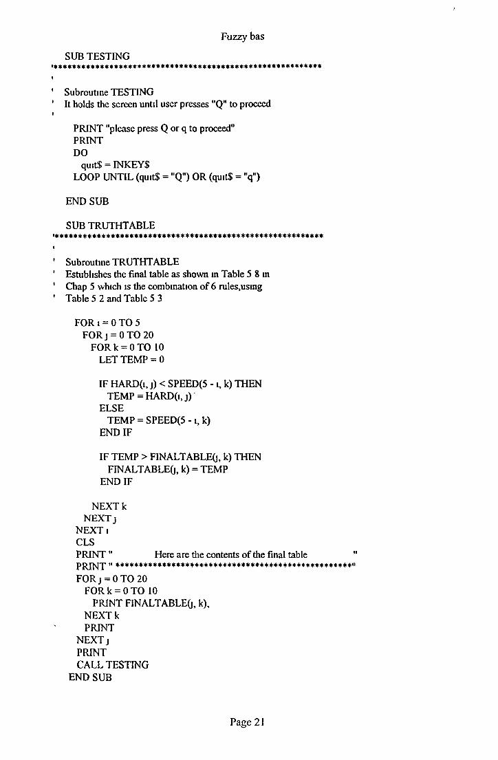
/
SUB TESTING**********************************************************
Subroutine TESTINGIt holds die screen until user presses "Q" to proceed
PRINT "please press Q or q to proceed"PRINTDO
quit$ = INKEYS LOOP UNTIL (quitS = "Q") OR (quitS = "q")
END SUB
SUB TRUTHTABLE * * * * * * * * * * * * * * * * * * * * * * * * * * * * * * * * * * * * * * * * * * * * * * * * * * * * * * * * * *
Subroutine TRUTHTABLE Establishes the final table as shown m Table 5 8 in Chap 5 which is the combination o f 6 rules,using Table 5 2 and Table 5 3
F O R i = 0 TO 5 FO Rj = 0 TO 20
FO Rk = 0 TO 10 LET TEMP = 0
IF HARD(i, j) < SPEED(5 - l, k) THEN TEMP = HARD(i, j)
ELSETEMP = SPEED(5 - i, k)
END IF
IF TEMP > FINALTABLEO, k) THEN FINALTABLEG, k) = TEMP
END IF
N EXTk NEXT j
NEXT i CLSPRINT " Here are the contents of the final table "PRINT " ***************************************************" FO Rj = 0 TO 20
FORk = 0 TO 10 PRINT FINALTABLEO, •<),
NEXTk PRINT
NEXT j PRINTCALL TESTING
END SUB
Fuzzy bas
Page 21

Fuzzy bas
SUB USEDATA**********************************************************
Subroutine USEDATA
Calls 4 other subroutines to find the cutting parameters requisted by the user
GETHARD 'Accepts material hardness(BHN) from user
GETTOOL 'Accepts tool name required by the user
GETREQFINISH 'Accepts required surface finish from the user
GETFILE 'Opens DATA file and performs all the'calculations based on the data m hand 'such as tool type, depth of cut,'material hardness(BHN) ect to find cutting speed 'and also prints the cutting parameters on screen 'for the metal cutting operation
END SUB
SUB USERMENU ***********************************************************
' Subroutine USERMENU' Calls OPMENU subroutine to display operator's menu 1 on the screen
CLSDO
OPMENUSELECT CASE userchoice
CASE 1matnameS - "medium carbon leaded"CALL USEDATA
CASE 2matnameS = "free machining carbon wrought"CALL USEDATA
CASE 3 CLSPRINT "***********************************************" PRINT "* Thankyou for using fuzzy expert system * "
PRINT "* Goodbye *"PRINT "************************************************"
CASE ELSE ERRORMESSAGE2 CALL TESTING
END SELECT LOOP UNTIL (userchoice = 3)
END SUB
Page 22

Fuzzy bas
\
Page 23


![Chapter 3: Fuzzy Rules & Fuzzy Reasoning513].pdf · CH. 3: Fuzzy rules & fuzzy reasoning 1 Chapter 3: Fuzzy Rules & Fuzzy Reasoning ... Application of the extension principle to fuzzy](https://static.fdocuments.net/doc/165x107/5b3ed7b37f8b9a3a138b5aa0/chapter-3-fuzzy-rules-fuzzy-513pdf-ch-3-fuzzy-rules-fuzzy-reasoning.jpg)