Future Directions of Supersonic Combustion Research-- Air Force-NASA Workshop on Supersonic...
40
1 Future Directions of Supersonic Combustion Research: Air Force/NASA Workshop on Supersonic Combustion Julian M. Tishkoff * Air Force Office of Scientific Research Bolling Air Force Base J., Philip Drummond ✣ NASA Langley Research Center Tim Edwards ❖ Abdollah S. Nejad ❖ Aero Propulsion and Power Directorate Wright-Patterson Air Force Base Abstract The Air Force Office of Scientific Research, the Air Force Wright Laboratory Aero Propulsion and Power Directorate, and the NASA Langley Research Center held a joint supersonic combustion workshop on 14-16 May 1996. The intent of this meeting was to: (1) examine the current state-of-the-art in hydrocarbon and/or hydrogen fueled scramjet research; (2) define the future direction and needs of basic research in support of scramjet technology; and (3) when appropriate, help transition basic research findings to solve the needs of developmental engineering programs in the area of supersonic combustion and fuels. A series of topical sessions were planned. Opening presentations were designed to focus and encourage group discussion and scientific exchange. The last half-day of the workshop was set aside for group discussion of the issues that were raised during the meeting for defining future research opportunities and directions. The following text attempts to summarize the discussions that took place at the workshop. Nomenclature A area a speed of sound C f skin friction coefficient D 1 Damkohler first number, L/ut c D 2 Damkohler second number, η c Δh c / H t E a activation energy e p flow distortion H t total flow enthalpy h t specific enthalpy L combustor length M Mach number Mc convective Mach number, (U 2 - U 1 )/(a 1 +a 2 ) n overall reaction order P pressure q dynamic pressure, 1/2(ρu 2 ) R 0 universal gas constant r velocity ratio, U 2 /U 1 s density ratio, ρ 2 /ρ 1 T temperature * Program Manager, Associate Fellow, AIAA ✣ Senior Research Scientist, Associate Fellow, AIAA ❖ Senior Research Scientist, AIAA Member
Transcript of Future Directions of Supersonic Combustion Research-- Air Force-NASA Workshop on Supersonic...
1
Future Directions of Supersonic Combustion Research:
Air Force/NASA Workshop on Supersonic Combustion
Julian M. Tishkoff *
Air Force Office of Scientific Research
Bolling Air Force Base
J., Philip Drummond C
NASA Langley Research Center
Tim Edwards v
Abdollah S. Nejad v
Aero Propulsion and Power Directorate
Wright-Patterson Air Force Base
Abstract
The Air Force Office of Scientific Research,
the Air Force Wright Laboratory Aero
Propulsion and Power Directorate, and the
NASA Langley Research Center held a joint
supersonic combustion workshop on 14-16
May 1996. The intent of this meeting was to:
(1) examine the current state-of-the-art in
hydrocarbon and/or hydrogen fueled scramjet
research; (2) define the future direction and
needs of basic research in support of scramjet
technology; and (3) when appropriate, help
transition basic research findings to solve the
needs of developmental engineering programs
in the area of supersonic combustion and fuels.
A series of topical sessions were planned.
Opening presentations were designed to focus
and encourage group discussion and scientific
exchange. The last half-day of the workshop
was set aside for group discussion of the
issues that were raised during the meeting for
defining future research opportunities and
directions. The following text attempts to
summarize the discussions that took place at
the workshop.
Nomenclature
A area
a speed of sound
Cf skin friction coefficient
D1 Damkohler first number, L/utc
D2 Damkohler second number, ηc ∆hc/ Ht
Ea activation energyep flow distortion
Ht total flow enthalpy
ht specific enthalpy
L combustor length
M Mach number
Mc convective Mach number, (U2-
U1)/(a1+a2)
n overall reaction order
P pressure
q dynamic pressure, 1/2(ρu2)
R0 universal gas constant
r velocity ratio, U2/U1
s density ratio, ρ2/ρ1
T temperature* Program Manager, Associate Fellow, AIAA
C Senior Research Scientist, Associate Fellow, AIAAv Senior Research Scientist, AIAA Member
Luo Wenlei
高亮

2
tc characteristic combustion time
U, u flow velocity
w laminar burning rate
Z altitude
∆hc heat of combustion
ηc combustion efficiency
ρ density
Subscripts
0 free stream condition
1, 2 stream 1, stream 2
4 isolator entrance condition
ad adiabatic flame conditionavg average valuemax maximum value
Introduction
This paper summarizes the discussions held at
an Air Force/NASA Workshop on Supersonic
Combustion, in Newport News, Virginia on
May 14-16, 1996. The purposes of the
workshop were: (1) to review current design,
performance, and testing practices for
scramjets -- supersonic combustion ramjets
used in high-speed airbreathing propulsion
systems; and (2) to investigate the application
of novel analytical methods, including
experimental, theoretical, and computational
approaches, to improve scramjet designs.
Recent programs for developing high-speed
aerospace vehicles that utilize airbreathing
propulsion provided the motivation for this
workshop. Many of these programs were
discussed at the recent AIAA 7th International
Space Planes and Hypersonics Systems and
Technologies Conference held in Norfolk,
Virginia on November 18-22, 1996. Despite a
high level of activity and financial investment
in scramjet development for high-speed flight,
no operational example of a scramjet currently
exists. The cancellation of the United States
National Aero Space Plane (NASP) program
reflects the difficulties in developing this mode
of propulsion successfully.
The intention of the organizers of the
workshop was to provide a unique forum in
which the developers and testers of
propulsion technology could interact directly
with members of the research community.
The workshop was organized to intersperse
formal presentations with open discussion in
order to find common ground between two
professional activities that otherwise might
not have opportunities for such direct contact.
To facilitate these interactions and
discussions, invitations to attend the
workshop were extended to approximately
sixty participants, as summarized in Table 1.
These participants were invited because of
their experience and records of
accomplishments in areas of research and
technology relevant to scramjet design and
testing. The organizers recognized that many
other scientists and engineers possess
knowledge and capabilities appropriate to the
workshop but believed that an excessively
large number of participants would hinder the
interactions. The presence or absence of any
scientist or engineer in Table 1 therefore does
not represent anyone’s opinion about the
professional merits of participants versus non-
participants.
The workshop was conducted over a 2-1/2
day period. The first two days were devoted
to presentations and related discussions. The
topics and presenters are listed in Table 2.
The body of this paper will review these
presentations. This paper also may contain
some additional ideas and comments that the
authors have assembled since the workshop
was held, but the primary content reflects the
presentations and related discussions at the
workshop. On the last half day of the

3
workshop an open discussion was conducted
in which general suggestions were made for
future activities. A brief summary of these
suggestions is given in Appendix A.
Table 1. Workshop Invitees
Name Affiliation
Mr. Griffin Anderson NASA Langley Research Center
Dr. Fred Billig Applied Physics Laboratory, Johns Hopkins
University
Dr. Garry Brown Princeton University
Dr. Dennis Bushnell NASA Langley Research Center
Dr. Harsha Chelliah University of Virginia
Dr. S M Correa GE Research Center
Dr. E. T. Curran WL/PO, Wright Laboratory
Dr. Stephen D'Alessio Applied Physics Laboratory, Johns Hopkins
University
Dr. Paul Dimotakis California Institute of Technology.
Mr. Glenn Diskin NASA Langley Research Center
Dr. James F. Driscoll University of Michigan
Dr. J. Philip Drummond NASA Langley Research Center
Dr. Craig Dutton University of Illinois
Dr. Raymond Edelman Rocketdyne
Dr. Tim Edwards WL/POSF, Wright Laboratory
Dr. Fokion N. Egolfopoulos University of Southern California
Dr. John Erdos GASL
Dr. G. M. Faeth University of Michigan
Dr. Alan Garscadden WL/CA, Wright Laboratory
Dr. Peyman Givi State Univ. of New York
Mr. Edward S. Gravlin WL/POP(HyTech), Wright Laboratory
Mr. Wayne Guy NASA Langley Research Center
Dr. R K Hanson Stanford University
Dr. William Heiser HQ USAF/DFAN Department of Aeronautics
Dr. Casey Jachimowski NASA Langley Research Center
Dr. Ajay Kumar NASA Langley Research Center
Dr. C K Law Princeton University
Dr. Ron Lehrach United Technologies Research Center
Dr. Frank Marble California Institute of Technology
Dr. Atul Mathur Rocketdyne Division, Rockwell International.
Corporation
Mr. Chuck McClinton NASA Langley Research Center
Mr. Bob Mercure NASA Headquarters
Lt Col Richard Moore WL/POP, Wright Laboratory
Dr. Abdollah Nejad WL/POPT, Wright Laboratory

4
Dr. G. B. Northam NASA Langley Research Center
Dr. Elaine Oran US Naval Research Laboratory
Dr. Gerald Pellett NASA Langley Research Center
Dr. S B Pope Cornell University
Dr. David Pratt University of Washington
Dr. David Riggins University of Missouri
Mr. Kenneth Rock NASA Langley Research Center
Dr. Clay Rogers NASA Langley Research Center
Dr. Klaus Schadow Naval Air Warfare Center
Dr. Joseph A. Schetz Virginia Polytechnic Inst. and State University
Dr. Munir Sindir Rocketdyne Division, Rockwell International
Corporation
Dr. Mike Smith NASA Langley Research Center
Dr. Louis Spadaccini United Technologies Research Center
Dr. Scott Thomas NASA Lewis Research Center
Mr. Michael Thompson Applied Physics Laboratory, Johns Hopkins
University
Dr. Julian M. Tishkoff AFOSR/NA
Mr. Carl Trexler NASA Langley Research Center
Dr. David Van Wie Applied Physics Laboratory, Johns Hopkins
University
Mr. Randy Voland NASA Langley Research Center
Dr. Robert W. Walters AeroSoft, Inc.
Dr. P J Waltrup Applied Physics Laboratory, Johns Hopkins
University
Dr. James Weber WL/POP
Dr. Al Wieting NASA Langley Research Center
Dr. Michael Winter United Technologies Research Center
5
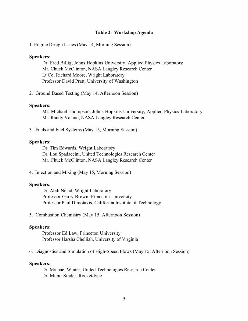
Table 2. Workshop Agenda
1. Engine Design Issues (May 14, Morning Session)
Speakers:
Dr. Fred Billig, Johns Hopkins University, Applied Physics Laboratory
Mr. Chuck McClinton, NASA Langley Research Center
Lt Col Richard Moore, Wright Laboratory
Professor David Pratt, University of Washington
2. Ground Based Testing (May 14, Afternoon Session)
Speakers:
Mr. Michael Thompson, Johns Hopkins University, Applied Physics Laboratory
Mr. Randy Voland, NASA Langley Research Center
3. Fuels and Fuel Systems (May 15, Morning Session)
Speakers:
Dr. Tim Edwards, Wright Laboratory
Dr. Lou Spadaccini, United Technologies Research Center
Mr. Chuck McClinton, NASA Langley Research Center
4. Injection and Mixing (May 15, Morning Session)
Speakers:
Dr. Abdi Nejad, Wright Laboratory
Professor Garry Brown, Princeton University
Professor Paul Dimotakis, California Institute of Technology
5. Combustion Chemistry (May 15, Afternoon Session)
Speakers:
Professor Ed Law, Princeton University
Professor Harsha Chelliah, University of Virginia
6. Diagnostics and Simulation of High-Speed Flows (May 15, Afternoon Session)
Speakers:
Dr. Michael Winter, United Technologies Research Center
Dr. Munir Sinder, Rocketdyne

6
Engine Design Issues
The workshop began with a review of current
practices for designing scramjet engines.
Practical system issues such as mission
requirements, integration of the inlet/isolator,
combustor, nozzle, airframe, fuel system
specification, and cooling concepts were
addressed. The objective of this session was
to discuss global design challenges associated
with both cryogenic and hydrocarbon-fueled
scramjets with the intent of identifying basic
research opportunities to impact scramjet
technology needs. However, at the time of the
workshop, the Air Force had already defined a
national program to develop technologies
required for the development of a fixed
geometry scramjet engine capable of operation
over Mach 4 - 8 flight regime using
conventional JP-based hydrocarbon fuels.
Therefore, the majority of the discussion
centered around technical challenges associated
with the development of tactical missiles using
storable fuels capable of acceleration from
Mach 4 and cruise at Mach 8.
For this discussion, high speed vehicles were
divided into the following two classes: a)
aircraft or man-rated; b) expendable. The
choice of high speed propulsion system
(airbreathing, and rocket) hinges on many
design and mission requirements. Factors such
as size, weight, design complexity,
maintainability, longevity, storability,
production and life cycle costs, and logistic
supportability were identified to be just as
important as the performance characteristics
(speed, range, and efficiency) of the
hypersonic vehicle. Billig [1] listed some of
the characteristics of hypersonic air-breathing
vehicles, see Table 3. It is interesting to note
that the combustor length remains virtually
constant at 2-6 ft for the three classes of
hypersonic vehicles, suggesting that
supersonic combustion processes are
inherently mixing-limited. The trade-off
strategy to attain high combustion efficiency is
much more complex in supersonic combustors,
where shear losses can drastically reduce
engine performance. Simply adding combustor
length for optimization of mixing/combustion
efficiency is usually not the prudent
engineering solution.
The choice of air-breathing ramjet engine
cycles depends on the flight Mach number.
For example, at lower flight Mach numbers
(M < 5 - 6) the subsonic integral rocket-
ramjet is the preferred cycle. At high Mach
numbers (M > 6 - 7) the scramjet cycle is the
preferred mode of operation. However, a
tactical missile -- an expendable, low cost, low
weight, and therefore fixed geometry flow path
design capable of operating at high flight Mach
numbers M > 6.5 using conventional storable
liquid hydrocarbon -- must operate as a ramjet
at low flight speeds and as a scramjet at
hypersonic speeds. Fortunately, if adequate
combustor-inlet isolation is provided, the
scramjet will function in a subsonic
combustion mode at low Mach numbers with
slightly lower efficiency than that of a
conventional ramjet. However, a
hydrocarbon-fueled scramjet designed to
operate efficiently at Mach 7 - 8 using a fixed
geometry flow path has not been shown to
operate efficiently at Mach 4 flight conditions
without resorting to use of massive auxiliary
piloting [2], or without the use of large
amounts of stored reactive oxidizer, e.g.,
chlorine trifluoride [3]. An interesting example
of a massively piloted scramjet concept is the
Dual Combustor Ramjet (DCR) which was
designed and tested at Johns Hopkins
University, Applied Physics Laboratory, and
is schematically shown in Figure 1. This is an
axisymmetric design in which the forebody

7
serves as the initial compression surface of the
supersonic inlet. In this concept, the incoming
flow is divided into eight segments at the cowl
lip. Four smaller inlets supply air to a
subsonic dump combustor. They operate
supercritically (the normal shock is
swallowed) to avoid the interaction of the
normal shock with the flow entering the larger
inlets that feed the supersonic combustor. In
order to provide stable combustor operation
over a wide range of flight Mach numbers, the
flow passages to the subsonic combustor have
an increasing cross sectional area in the
streamwise direction. The major portion of
the air is captured by the four larger inlets and
the external cowl compression surface and
turned supersonically inward toward the
engine axis. Captured flow is spread radially
to form an annulus of supersonic flow that
surrounds the outlet of the dump combustor.
The aft sections of these supply ducts have
slightly diverging flow passages in the
streamwise direction, which effectively act as
the combustor-inlet isolator. When the
propulsion system is operating at a high
equivalence ratio and/or at low flight Mach
numbers, the isolator section can sustain a
shock train with a pressure rise equivalent to
that of normal shock. In this mode of
operation the combustor inlet Mach number is
less than one, and the mean Mach number at
the combustor exit is either sonic or
supersonic. At lower engine equivalence ratios
and/or higher flight Mach numbers the isolator
shock train pressure rise is equivalent to that
of an oblique wave structure. With the
inlet/isolator operating in the oblique shock
mode, the mean flow Mach number
throughout the scramjet is supersonic. This
dual-mode engine operation has been discussed
fully in the literature [4-6].
The issue of coupling combustor burner
characteristics to vehicle cooling requirements
is very important. The endothermicity of
hydrocarbon fuels requires vehicle structural
components to act as a heat exchanger/thermal
cracking reactor. The composition of the
cracked products depends on the time-
temperature history of the cracking process
throughout the vehicle structure. Changes in
chemical composition or the state of the fuel
directly affect burner operational
characteristics; the time required for a radical
pool to reach flammable conditions is linearly
dependent on concentration, quadratically
dependent on pressure, and exponentially
dependent on the temperature. Therefore,
precise control of the thermal cracking process
is essential to the production of the desired
fuel conversion (constituents) at the burner
entry throughout the flight trajectory.
However, the coupling of the heat
exchanger/reactor to the combustor is not
without its engineering challenges. Many tests
of heat exchanger reactors have shown severe
acoustic instability, leading to catastrophic
failure. Tests of regeneratively cooled
structures with endothermic fuels feeding a
combustor have shown system instabilities
between the two systems. The source of
these acoustic instabilities may be the fact that
hydrocarbon fuel remains near the
thermodynamic critical point within the heat
exchanger, where thermodynamic properties
such as density, viscosity, latent heat, ratio of
specific heats, and speed of sound show large
variations with respect to small changes in
temperature and pressure.
Mixing and heat release are significant
engineering challenges in supersonic flows.
However, when the engineer considers all
aspects of the system design, mixing
optimization, and/or combustion efficiency
may not be the driving factors. Thus,

8
combustor and isolator lengths may not dictate
the internal duct length. Since the internal drag
can reduce the performance of a scramjet
engine significantly, combustor designs with
large surface areas should be avoided.
Furthermore, the designers are usually careful
in using intrusive injectors. Aside from the
severe cooling requirements, the base and wave
drag of many hyper-mixers render them
ineffective in a practical device. Therefore,
one must optimize and balance system overall
performance, (i.e., maximizing net positive
thrust), at the expense of not achieving
complete mixing.
To develop a scramjet, designers require a
design strategy. The following process was
proposed: (1) start with a conceptual vehicle
design; (2) optimize the design by sensitivity
analysis; (3) select inlet(s), and conduct inlet
tests, preferably in conjunction with the
isolator, combustor, and injector components;
(4) analyze the experimental data to update
the cycle analysis codes to assess the
performance potential of the scramjet design;
(5) optimize the combustor/injector design
concept. In order to implement this design
strategy, accurate models for predicting jet
penetration, mixing, combustion, heat transfer,
and combustor-inlet interaction are required.
To develop such models, research efforts must
be ongoing for better understanding of the
physics of supersonic combustion to evaluate
and update the empirical design models used
by the engineers. Free jet, semi-free jet, and
direct connect tests must be conducted in
sufficient detail to allow meaningful
assessment of the performance and operational
characteristics of the design and generation of
benchmark data to aid with the development
and validation of the analytical tools.
Ground Testing
The objective of this session was to introduce
and discuss the state of testing and
measurement technology used for assessment
of scramjet performance in ground based
facilities. The speakers outlined test
procedures, instrumentation and measurement
accuracy requirements, analytical modeling of
the aerothermochemical processes, and error
analysis procedures used for performance
testing of the scramjet flow path.
Conventional ramjets and scramjets designed
for Mach 6 - 8 flight push the limit of long
duration (~ seconds to minutes) ground test
direct-connect or free-jet test facilities.
Mission FlightMach #
PropulsionSystem
Flow PathGeometry
Fuel FlightDuration
Vehicle length(ft)
TacticalMissile
6 - 8 Dual CombustorRamjet and/or
Rocket
FixedGeometry,passivelycooled
Liquid HC,Slurry,
Solid HC
10 -12Minutes
Overall 5 - 15Combustor 2 - 5
Nozzle 2 - 5
Trans-atmospheric
Missiles
0 - 25 Dual modeRamjet/Scramjet +many low speed
options
VariableGeometry
Liquid H2
Liquid O2
20 - 30Minutes
100 cycle
Overall 100- 200Combustor 2 - 6Nozzle 50 - 80
HypersonicCruise
0 - 80 - 15
Mach 6-8Turboramjet
M 15 scramjet
VariableGeometry,ActivelyCooled
Mach 6-8,HC
Mach 15,Liquid H2
M = 6 - 8, 1 - 3 Hours
M = 151 Hour
Overall 100- 200Combustor 2 - 6Nozzle 50 - 80
Table 3. General Characteristics of Hypersonic Vehicles

9
Higher speed flight conditions (M >10) are
simulated in pulsed facilities that can generate
flight enthalpies in excess of M = 15
conditions, but only for a few milliseconds. In
this session most of the discussion centered
around testing scramjets in direct-connect and
free-jet facilities. Figure 2 is a schematic
illustration of a direct connect test facility.
These facilities are relatively straightforward
and are composed of the following key
elements: (1) a high pressure air source; (2) an
air heater (vitiated/arc-heated/pebble-bed/gas
fired heat exchanger) for proper simulation of
flight enthalpy; (3) a facility nozzle for proper
simulation of combustor/isolator inlet Mach
number in direct-connect tests or flight Mach
number in free-jet tests; (4) a combustor
and/or scramjet test article; (5) a load
measuring system for thrust measurement; and
(6) a steam calorimeter for estimation of
combustion efficiency. Typical scramjet
combustor entrance properties [7] are depicted
in Table 4. In theory, it is desirable to
duplicate or match these properties as closely
as possible. However, practical requirements -
- such as: power generation; fabrication of
hardware to sustain the pressure; and facility
and model cooling requirements for testing at
flight enthalpy, which increase linearly with
facility size (mass flow rate) and quadratically
with flight Mach number-- may prevent
duplication of all flight parameters. Anderson
et al. [8] defined pressure, temperature,
velocity, gas composition, and characteristic
length scale as the primitive variables that
describe the scramjet flowfield. Voland and
Rock [9] have pointed out that, since complete
duplication of the flight parameters in ground
test facilities may not be possible, then one
must identify parameters that impact the
physical processes of supersonic combustion.
It is generally agreed that these parameters are:
flight Mach number, total enthalpy, Reynolds
number, Stanton number, Damkohler first and
second numbers, and the wall enthalpy ratio.
Voland and Rock observed that the process of
matching flight total enthalpy and Mach
number allows proper simulation of the
Damkohler second number D2 -- the kinetic-
to-thermal energy ratio. If the flight dynamic
pressure is not matched due to power
requirements or facility constraints and mass
flow limitations forces, testing a smaller scale
engine becomes necessary. Then the
Damkohler first number D1 -- the ratio of flow
residence time to chemical reaction time -- is
not simulated properly. If combustion is
kinetically limited, then ignition delay
characteristics of the fuel and the reaction
times become a critical issue, and proper
simulation of D1 becomes critical. However, if
the combustion is mixing limited, proper
simulation of D1 is not an issue. Dynamic
pressure and geometric scaling also affect the
ratio of the inertial to viscous forces
(Reynolds number). Recall that the Reynolds
number was identified as an important
parameter to match in ground testing of
engines. When scaling reduces the flow path
size excessively, then one should question the
extrapolation of the results due to mixing,
shock-boundary layer interaction, boundary
layer thickness, injector nozzle discharge
coefficient, etc.
With few exceptions, instrumentation in these
facilities is rather conventional and is limited
to electromechanical devices for measuring
pressure, temperature, gas composition,
thrust, and combustion efficiency. Complexity
and safety requirements compound the
difficulty of incorporating advanced laser-
based diagnostic techniques. Most often,
steam calorimetry is used in long duration test
facilities to quantify the amount of energy
release, hence combustion efficiency. Several

10
accurate measurements must be made to
account for a proper energy balance from the
heater to the calorimeter exit plane. These
include: temperatures and flow rates of air,
make up oxygen, fuel (heater and combustor),
quench water, total temperature at the exit
plane of the calorimeter, and heat loss through
the facility nozzle and combustor walls. In
this technique, water is injected downstream
of the combustor exit plane to rapidly quench
chemical reactions. The precision of the total
temperature measurement at the calorimeter
exit plane significantly impacts the analysis
and the results. Stevens and Thompson [10]
schematically illustrate the procedures used
for analysis of an arc-heated facility, Figure 3.
They also point out that various issues, such
as precise determination of the heater
stagnation condition, facility nozzle effective
flow rate and discharge coefficient, combustor
entrance and exit conditions, and calorimeter
exit conditions are extremely important for
precise estimation of scramjet combustion
efficiency using a steam calorimeter.
In general it is recommended that, in addition
to steam calorimetry, other measurements
such as thrust, combustor pressure
distribution, skin friction, Pitot pressure, and
gas sampling should also be attempted. Table
5 shows the relative accuracy of the derived
combustion efficiency (ηc) and the skin
friction coefficient (Cf) as functions of
measured parameters.
Free Stream Conditions Isolator entrance Conditions
Mo Zo (Kft)Po
(psia)To(
oR)
Uo(ft/sec)
qo(lbf/ft2)
hto(BTU/lbm) M4 Ao/A4 P4/Po
P4
(psia)T4
(oR)
U4
(ft/sec)
3 47.95 1.868 390 2904 1694 133.3 1.529 2.86 7.8 14.51 744 2034
4 57.48 1.183 390 3872 1910 264.3 1.945 4.91 15.7 18.57 930 2885
5 65.72 0.7978 390 4840 2011 432.8 2.363 6.92 24.9 19.86 1102 3799
6 73.30 0.5569 394 5839 2020 646.7 2.767 8.91 35.3 19.65 1279 4770
7 80.07 0.4049 397.7 6844 2000 902.3 3.143 10.85 47.0 19.03 1451 5757
10 95.50 0.1984 406.1 9879 2000 1918.2 4.143 16.49 89.6 17.78 1958 8744
15 114.25 0.0857 424.8 15155 1945 4561.0 5.502 25.23 185.9 15.94 2880 13908
20 137.76 0.0319 460.8 21040 1287 8824.3 6.650 33.11 313.6 10.02 4074 19468
26.9 178.21 0.0067 480.5 28865 425.8 16629.8 7.688 40.12 472.9 3.20 5187 27205
Table 4. Typical ramjet/scramjet freestream and combustor inlet conditions
Measurement ηc Cf
Static Pressure Good Fair
Temperature Good Poor
Water Concentration Good Very Poor
Total Pressure Poor Good
Velocity Very Poor Very Poor
Table 5. Measurement Sensitivity

11
Fuels and Fuel Systems
"Fuel is becoming the integrating factor of the
complete {high-speed vehicle} system” --E. T.
Curran in [11]. "The problem is, we don't
know how to make the scramjet combustor
work efficiently using conventional fuels at
low flight speeds corresponding to end-of-
boost" -- F. Billig at this workshop.
There have been many recent workshops [11-
13] and books [14, 15] in the supersonic
combustion area that included discussions of
fuels issues. A general consensus is: storable
JP-type hydrocarbon fuels can be used up to
Mach 6-8, although the upper end of this
range will be a significant technical challenge
that will require chemically reactive
"endothermic" fuels. Lou Spadaccini of
United Technologies Research Center briefed
the workshop on endothermic fuels [16].
Liquid methane could be used to somewhat
higher Mach numbers, but speeds in excess of
about Mach 10 will require liquid hydrogen.
Air Force perspective
With the demise of NASP, the Air Force (AF)
has focused its high-speed propulsion effort
on storable hydrocarbon-fueled vehicles.
Storable-fueled hypersonics is viewed as an
important technology for the AF for various
future missions [17]. However, hydrocarbon
fuels have significant shortcomings in
supersonic combustion when compared to
hydrogen, notably relatively long ignition
delays and limited cooling capability [12, 13].
One issue that needs to be addressed in
practical engine design is the transition of the
fuel injection and combustion processes that
occur as the fuel temperature rises in the
vehicle cooling passages. Early in the flight,
cooling requirements are minimal, and the fuel
is injected in a liquid phase. As the flight
progresses and the flight speed increases, fuel
may be heated to be well above its
thermodynamic critical point. In both
advanced gas turbines and scramjet engines,
the fuel may be partially reacted (cracked or
dehydrogenated) through its use as a coolant
before reaching the combustor. It is of
significant AF interest to determine the effect
of this change in fuel character on the
combustion process. It is anticipated that this
partially reacted fuel will burn as well as, say,
ethylene, with some claims that the
combustion properties (such as ignition delay
or reactivity) may approach or exceed that of
hydrogen. Appropriate questions that need to
be addressed are: (a) will the ignition delay of
a partially cracked or dehydrogenated fuel
under engine conditions approach that of (e.g.)
ethylene or even hydrogen; and (b) how will
the combustion efficiency/reactivity of a fuel
change as it is heated and is partially reacted in
the fuel system. The first step in kerosene-
range hydrocarbon fuel combustion is often
cracking of the C12-level molecules to C1-C3
species. How will the combustion process be
affected if these cracking reactions occur
"upstream" of the combustor?
The use of fuel as a coolant in advanced
engines can lead to thermal and catalytic
reactions in the fuel, yielding H2, CH4, C2H4,
C2H6, etc. [16, 18-21]. As these partially
reacted, hot (e.g., 1200 0F/650 0C) fuels are
injected into a gas turbine or scramjet
combustor, it is appropriate to consider how
the hot, partially reacted state of the fuel
might affect the combustion process. As the
liquid fuel is heated at pressure, it becomes a
supercritical fluid with significantly different
physical properties, such as density and
viscosity [29]. This could be expected to
significantly change injection behavior [30].
As the fuel begins to react in the fuel system,
chemical changes in the injected fluid could

12
also affect the combustion process. For
example, ignition is considered to be a "radical-
poor" process [22], and ignition delay is
affected by radicals present due to air vitiation
[23]. Are there sufficient radicals present in
the "reacted" fuel at ~ 1200 0F to reduce
ignition delay in a similar manner? In some
cases, the reacted fuel can contain large mole
percent levels of H2, especially for
endothermic fuels such as methylcyclohexane
that are dehydrogenated. Does this H2 content
improve the ignition delay? Note again that
the relatively long ignition delay time of
hydrocarbons relative to H2 is a key limitation
for hydrocarbon-fueled scramjets [12, 13].
There is evidence from shock tube tests that
the ignition delay of hydrocarbons is reduced
by the presence of hydrogen, but still is orders
of magnitude larger than that for pure
hydrogen [24]. The kinetics of combustion are
also of interest. Does the reacted fuel burn in
a manner similar to its measured stable
constituents, or does the presence of
(significant?) amounts of hydrocarbon radicals
change the reactivity? Another factor affecting
combustion is that significant fractions of
hydrogen could be generated in the fuel fed to
the combustor either by fuel dehydrogenation
or by "steam reforming" a fraction of the fuel
{CxHy + xH2O → xCO + (x+0.5y)H2}. An
issue that may be significant is the effect of
coke particles or soot precursors in the reacted
fuel on combustion. Coking is a significant
issue for high temperature fuels [16, 18, 25],
and some fuels may form aromatics as part of
the cracking process. Supercritical fuel
increases the solubility of coke precursors
(oligomers) from catalysts [26, 27]. How will
these fuel-borne aromatics, particulates, and
oligomers affect soot formation (and thus
radiative heat loads in the combustor and
emissions)?
The consensus at the workshop appeared to
be that the answers to most of these questions
are not known. To obtain this information, it
was suggested that the effects of changes in
the fuel must be studied in a realistic
simulation of the scramjet combustion
process, i.e. one that represents the diffusive
nature of the combustion. One sub-scale
possibility is co-annular or opposed-jet
burners [28] that would burn hot, partially
reacted fuels. Premixed combustion devices
appear to be inadequate to address the
important issues.
NASA Perspective on Fuels
The NASA Langley Research Center (LaRC)
has been examining both hydrogen and
hydrocarbon-fueled hypersonic vehicles
concepts, including dual-fueled (H2 + HC)
vehicles. Dual-fueled systems have
advantages, as demonstrated by the dual-
fueled Apollo missions. Chuck McClinton
briefed the workshop on the status of LaRC’s
scramjet work in these areas. NASA studies
have confirmed the Mach 7-8 limit for
hydrocarbon-fueled vehicles. NASA work, as
discussed above, has shown the ignition,
combustion, and cooling difficulties of
hydrocarbon fuels. Hydrogen is a much better
scramjet fuel, except in the areas of volumetric
fuel energy density and logistical
supportability. Published NASA vehicle
designs for both hydrocarbon-fueled [31] and
hydrogen-fueled [32] vehicles were mentioned.
NASA is supporting the Air Force HyTech
program with analysis and modeling, although
the primary focus of NASA/LaRC’s work is
flight tests of a H2 dual-mode scramjet system.
Combustion Chemistry
This portion of the workshop addressed the
identification of detailed chemical kinetic
mechanisms for scramjet combustion and the
13
reduction of those mechanisms to produce
kinetic models for combustor design codes.
Discussions were also directed at approaches
to model turbulence-chemistry interactions.
The computational complexity of solving
turbulent fluid transport equations provides a
strong incentive for simplifying the
description of chemical kinetics as much as
possible in combustor design codes. The
degree of success of such simplifications
depends on the information that is required for
each calculation. For example, equilibrium
chemistry is adequate for calculations of non-
optimum, non-critical global performance and
has been used successfully for such
applications as predicting overall energy
release in internal combustion engines.
However, the accuracy of simplified or
reduced chemistry must be scrutinized
carefully for other calculations.
An example of the limitations of simplified
chemical kinetic models can be found in the
calculation of laminar flame propagation using
one-step global chemistry [33]. Equation 1
provides an Arrhenius expression to represent
one-step model for the laminar burning rate w:
w ~ Pn/2 exp[-Ea/2R0Tad] (1)
where symbols are defined in theNomenclature.
The simplest form of the one-step expression
would have n as a constant. However, even if
n were treated as a pressure-dependent
variable, this expression can be shown to be
deficient.
To test the validity of eq. (1) with n as a
variable, Egolfopoulos and Law [33] measured
the laminar flame propagation of methane-
oxygen-nitrogen mixtures in a counterflow,
twin-flame configuration. Figures 4-5 show
the behavior of the laminar burning rate w and
the overall reaction order n, respectively.
According to eq. (1) w should exhibit a
monatonic, exponential dependence on
pressure. Figure 4 does not confirm this
dependence. Figure 5 shows that the exponent
n is always less than 2, which is incompatible
with n as a constant. n also has considerable
variation with pressure and even can assume
negative values. Thus, eq. (1) is a poor
estimator of laminar flame behavior.
The physicochemical basis for the deficiency
of eq. (1) lies in the inability to account for the
complexities of the competition between two-
body chain branching reactions and multibody
termination reactions in determining flame
propagation. The presence of nonreactive
third bodies to serve as collision sites in the
termination reactions makes these reactions
particularly sensitive to pressure.
If more complex reduced chemical mechanisms
are needed, then how are they to be derived?
The essential first step in producing reduced
kinetic mechanisms is the identification of
complete chemical reaction mechanisms for
representative fuel combustion conditions.
For hydrogen fuel, this process is
straightforward. For example a complete
chemical reaction mechanism for H2-O2-CO2
can involve 13 species and 27 reaction steps.
However, for hydrocarbon fuels, it is more
complex and difficult. Even a simple methane-
air mechanism can include 16 species with 40
reaction steps, while hydrocarbon-air
combustion chemistry can involve 40 species
with 100 reaction steps for more complex
hydrocarbon species. In hypersonic
applications, with fuel needed for cooling
purposes, the identification of specific fuel

14
components represents the initial challenge.
For example, recent testing of endothermic
fuels suggested that ethylene was a major
product of endothermic catalytic reactions
[16]. However, more recent results, as
discussed by Edwards in this workshop,
contradict this choice. Processes such a soot
formation remain elusive because of their
complexity.
A second obstacle to the measurement of
complete reaction mechanisms is limitations in
reactor and diagnostic capabilities. Kinetics
must be measured under thermodynamic and
fluid dynamic conditions that simulate high
speed propulsion environments. Note that,
measurement capability must be adequate for
all critical species.
Two steps are generally used for simplifying
chemical kinetic mechanisms: development of
“starting” mechanisms and “reduced”
mechanisms. The starting mechanism
represents a subset of the detailed mechanism,
obtained by elimination of elementary
reactions to diminish the number of total
species in the system by as much as 90%.
Further simplifications of the starting
mechanism may be achieved by the
introduction of systematic “reductions” based
on the chemical and flow time scales of the
problem. Since calculation times ~ (number
of species)2, these simplifications can produce
dramatic savings in computational time.
Two approaches have been identified to
produce starting mechanisms:
1. “Systematic” approaches first use intuitive
arguments to eliminate noncritical species
and then use sensitivity analysis to reduce
the number of reaction steps. Peters [34]
introduced steady-state or partial
equilibrium approximations to achieve
such simplifications. This approach raises
concerns that the results may be specific
to the type of flame being calculated.
2 Automated procedures. This systematic
approach produces mechanisms that span
the full range of known experimental
results and should not be unique to any
individual experiments. Automated
reaction procedures have been suggested
by Lam [35], Chelliah [36], and Pope [37].
This approach has been applied to
unsteady zero dimensional (homogeneous)
systems but not as yet to combustion
involving diffusive transport. Figure 6
[36] illustrates the application of this
approach to predict heat release in a
nonpremixed counterflow methane-air
flame. This figure shows a comparison
between a 16 species, 40 reaction step
starting mechanism and two systematically
reduced mechanisms, developed by
introducing steady state approximations.
A 31% representative saving in
computational time may be expected from
such reductions. Similar calculations are
underway for oblique detonation wave
combustion.
A strategy was suggested to implement
automated reduction:
1. Obtain a detailed, comprehensive data base
for C7-C12 aliphatic fuels.
2. Select a surrogate fuel.
3. Derive [34-37] an appropriate reduced
mechanism for the intended application.
Table lookup procedures were suggested in the
workshop as an alternative to embedded
15
solution of reduced chemical kinetic equations
in combustion calculations. Lookup methods
are linearly proportional to the number of
species, as opposed to the quadratic
dependence noted above for reduced
mechanisms. The utility of lookup procedures
depends on computational efficiency. Pope
[37] recently has suggested novel methodology
to accelerate table lookup.
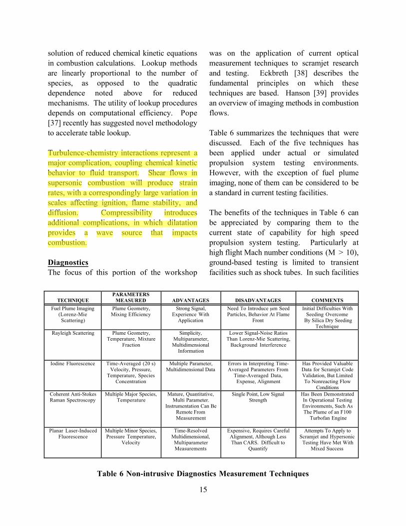
Turbulence-chemistry interactions represent a
major complication, coupling chemical kinetic
behavior to fluid transport. Shear flows in
supersonic combustion will produce strain
rates, with a correspondingly large variation in
scales affecting ignition, flame stability, and
diffusion. Compressibility introduces
additional complications, in which dilatation
provides a wave source that impacts
combustion.
Diagnostics
The focus of this portion of the workshop
was on the application of current optical
measurement techniques to scramjet research
and testing. Eckbreth [38] describes the
fundamental principles on which these
techniques are based. Hanson [39] provides
an overview of imaging methods in combustion
flows.
Table 6 summarizes the techniques that were
discussed. Each of the five techniques has
been applied under actual or simulated
propulsion system testing environments.
However, with the exception of fuel plume
imaging, none of them can be considered to be
a standard in current testing facilities.
The benefits of the techniques in Table 6 can
be appreciated by comparing them to the
current state of capability for high speed
propulsion system testing. Particularly at
high flight Mach number conditions (M > 10),
ground-based testing is limited to transient
facilities such as shock tubes. In such facilities
TECHNIQUE
PARAMETERS
MEASURED ADVANTAGES DISADVANTAGES COMMENTS
Fuel Plume Imaging(Lorenz-MieScattering)
Plume Geometry,Mixing Efficiency
Strong Signal,Experience With
Application
Need To Introduce µm SeedParticles, Behavior At Flame
Front
Initial Difficulties WithSeeding Overcome
By Silica Dry SeedingTechnique
Rayleigh Scattering Plume Geometry,Temperature, Mixture
Fraction
Simplicity,Multiparameter,Multidimensional
Information
Lower Signal-Noise RatiosThan Lorenz-Mie Scattering,
Background Interference
Iodine Fluorescence Time-Averaged (20 s)Velocity, Pressure,
Temperature, SpeciesConcentration
Multiple Parameter,Multidimensional Data
Errors in Interpreting Time-Averaged Parameters From
Time-Averaged Data,Expense, Alignment
Has Provided ValuableData for Scramjet CodeValidation, But LimitedTo Nonreacting Flow
Conditions
Coherent Anti-StokesRaman Spectroscopy
Multiple Major Species,Temperature
Mature, Quantitative,Multi Parameter.
Instrumentation Can BeRemote FromMeasurement
Single Point, Low SignalStrength
Has Been DemonstratedIn Operational TestingEnvironments, Such AsThe Plume of an F100
Turbofan Engine
Planar Laser-InducedFluorescence
Multiple Minor Species,Pressure Temperature,
Velocity
Time-ResolvedMultidimensional,MultiparameterMeasurements
Expensive, Requires CarefulAlignment, Although LessThan CARS. Difficult to
Quantify
Attempts To Apply toScramjet and Hypersonic Testing Have Met With
Mixed Success
Table 6 Non-intrusive Diagnostics Measurement Techniques
Luo Wenlei
高亮
Luo Wenlei
高亮
Luo Wenlei
高亮

16
time per test can be limited to milliseconds,
with only a few tests per day. Thus, data
acquisition becomes a primary factor in
establishing the duration and cost of any
testing program.
Methods currently used in scramjet testing
include electromechanical devices such as
thermocouples and pressure transducers for
quantitative information, photographic and
videographic image recording, spontaneous
emission spectroscopy, and mechanical
sampling. The electromechanical devices are
point measurement techniques, so that an
extensive array is needed to determine time-
resolved spatial variations in temperature and
pressure. These measurements are intrusive
into the flowfield if they are mounted on
probes. Otherwise they are restricted to
surface characterization.
Image recording can be based on emitted light
or on shadowgraph or schlieren approaches,
which utilize a light source. Images recorded
in this manner provide path-averaged,
qualitative interpretations of flowfield
behavior. Attempts have been made to expand
schlieren capability by spectrally-resolved
recording (color schlieren).
Sampling and spontaneous emissions
spectroscopy have provided data on
combustion chemistry. Sampling is a point
measurement that is not temporally resolved.
The extraction of the sample also can allow
additional chemical reactions to occur in the
sample, representing a source of error in the
measurement. Spontaneous emissionspectroscopy shares the path averaginglimitations of image recording methods andrequires assumptions regarding excited statepopulation fractions.
As indicated in Table 6, recent advances in
laser-based measurement techniques offer the
hope of overcoming many of the limitations
noted above for current measurements.
However, the application of these methods to
practical testing environments is in its infancy,
and lessons learned thus far show that the
application process generally will not be
straightforward or easy.
In Table 6 the results for fuel plume imaging
were based on seeding the injected fuel with
silica (SiO2) particles as scattering sites for
light. As noted in the table, initial problems
were encountered by approaches to create
these particles through the reaction of silane
with oxygen according to the following
reaction mechanism:
H2 + SiH4 + 2O2 → H2 + SiO2(s) + 2H2O + heat
These approaches produced some problems
with nonuniform particle size and particle
agglomeration. Furthermore, water vapor
would then be present in the fuel as a
consequence of this chemical reaction.
Subsequently, an alternative approach in
which uniform size silica particles were seeded
directly into the fuel prior to injection
removed this difficulty. For both approaches
particle agglomeration and residues proved to
be problems. Particle vaporization also was a
concern, and the technique worked best for
noncombusting tests, in which fuel was
injected into nitrogen gas.
Experience with the optical methods of Table
6 has indicated some common areas of
concern:
1. Windows. Optical access is a major design
concern for a test apparatus. Proper
design requires windows to be sufficiently
durable and not to alter system behavior.

17
If cleaning or replacement is required, then
ease in performing these maintenance
functions should be incorporated into the
design of the apparatus.
2. Noise and vibration. Noise should be
considered in the general electromagnetic
sense. Electrical noise from flow
generating equipment and from
instrumentation can be a significant
interference to low amplitude signal
generation. The Lorenz, Mie, and
Rayleigh scattering techniques in Table 6
are examples of elastic scattering, in which
the signal radiation is at the same
wavelength as the incident radiation.
Therefore, spectral filtering methods to
reduce background radiation may be more
difficult than with the laser-induced
fluorescence and coherent anti-Stokes
Raman measurements. Mechanical
vibrations represent a serious challenge to
optical alignment and the durability of
optical components and lasers.
3. Extreme thermodynamic conditions. The
high temperatures and pressures associated
with combustion testing represent a hazard
to both measuring equipment and human
operators. In some previous tests
measurement system design required a
capability for remote adjustment and
alignment while measurements were being
performed.
4. Environmental and safety regulations. The
safety requirements for propulsion test
facilities and those for the operation of
laser-based measurement instrumentation
are not always directly compatible.
Recent experience at one scramjet testing
facility that was located outdoors near an
airport necessitated enclosing laser beams
to shield them from nearby aircraft. These
considerations impose additional design
requirements that are not directly related
to the measurements.
The potential benefits of the methods listed in
Table 6, as well as other methods currently
under study, must be taken into consideration
in future scramjet development programs.
Although these methods generally have not
been utilized sufficiently to make their
application easy as yet, in some cases unique
and extremely valuable data have been
obtained that could not be measured by any
other means. The rapid advancement of
optical measurement technology, including
such developments as fiber optics and diode
lasers, should facilitate their adoption in the
future. Furthermore, routine usage should
simplify measurement practices, so the
participation of Ph.D spectroscopists will not
be required.
Simulation
The role of computational fluid dynamics
(CFD) in the design of a hypersonic
propulsion system was described by Sindir in
this session. The application of
computational techniques to major scramjet
components, including the inlet/isolator,
combustor, and nozzle, was first discussed.
The relevant flow physics in each component
was considered, followed by the current
approaches for analyzing that flowfield.
Deficiencies in the current approaches were
then described, and new technology required
to deal with these deficiencies were discussed.
The experiments and data needed to validate
the computational tools applied to each
component were also discussed. Following
the discussion of the analysis and design of
individual engine components, modeling of the
integrated flow path was considered.
Luo Wenlei
高亮

18
CFD has several roles in the design of a
hypersonic propulsion system. It primarily
serves as an engineering tool for detailed design
and analysis. In addition, results from CFD
analyses provide input data for cycle decks
and performance codes. Finally, CFD has
several uses in engine test programs used to
develop an engine concept. CFD is first used
to guide the test setup and to determine the
proper location for the placement of
instrumentation in the engine. It has also
proven to be an effective tool for determining
the effects of the facility on testing, for
example, the effects of contaminants in a
combustion heated facility on an engine
combustor test. During and following a test,
CFD is useful to predict flowfield
measurements as a complement to measured
data.
The inlet/isolator of a scramjet engine supplies
the combustor with a required quantity of air
at a specified pressure, velocity, and flow
uniformity. The physics of the flow in an
inlet are characterized by:
1. Moderate strength shock waves
2. Shock-boundary layer interactions
3. Flow separation in unfavorable pressure
gradients
4. Compressibility effects
5. Transition to turbulence
6. High leading edge thermal loads
7. Possible unstart
Computational analyses of inlets typically
employ codes that solve the Euler equations or
Euler iterated with the boundary layer
equations for viscous effects for initial
analyses. More detailed calculations utilize
either the parabolized Navier-Stokes equations
or the full Navier-Stokes equations if
significant flow separation must be considered.
All of the calculations typically solve the
steady-state equations so that the simulations
can be completed in reasonable times.
Turbulence is modeled using either algebraic or
two-equation turbulence models with
empirical compressibility corrections and wall
functions. Transition models are not currently
being employed. Thermodynamic properties
are generally determined by assuming that the
inlet flow behaves as a perfect gas or
equilibrium air. Calculations are conducted on
fixed grids of 100,000 to 2,500,000 points in
multizone domains. A limited degree of
dynamic grid adaptation is employed when
necessary. Typical run times range from a few
minutes to 50 hours on a Cray C-90 computer.
A typical high-speed inlet calculation by
Sindir is shown in Figure 7. The inlet shown
in the figure utilizes side wall compression to
achieve the desired outflow conditions into a
combustor. The flow in the inlet is modeled
using a full Navier-Stokes code with an
algebraic turbulence model. The calculation is
conducted on a grid of 240,000 points.
Computed pressure contours are
superimposed on the picture of the inlet. The
plot in the figure shows a comparison between
the computed wall pressures plotted as a
function of downstream distance and measured
data. The agreement between the computation
and the measured data is excellent. Data away
from the inlet walls is not available for
comparison.
Based on the current state of the art for inlet
calculations and the future technology needs,
the following advancements are needed. More
efficient parabolized and full steady-state
Navier-Stokes codes with a factor of five
increase in run time efficiency are needed.
Significant improvements are also required for

19
temporal Navier-Stokes codes for the analysis
of unsteady inlet flowfields, including inlet
unstart. Improvements should occur with
algorithmic advancements, with one promising
area being multigrid methods [40]. Continuing
advancements in computer architectures will
also enhance code speed. Improved methods
for dynamic grid adaptation would also
enhance the ability of computational
algorithms to capture flowfield features.
There is a serious need for the development of
advanced transition and turbulence models.
This is likely the most limiting area for
accurate modeling of inlet flowfields.
Promising work is now underway to develop
new algebraic Reynolds stress turbulence
models with governing equations that can be
efficiently solved [41, 42]. For nonequilibrium
flows, the differential Reynolds stress
equations must be solved, however, and
further work is necessary for this to be done
more efficiently. Advances in large eddy
simulation, with the development of subgrid
scale models appropriate to high-speed
compressible flow, may also allow this
technique to be applied to inlet flows in the
future [43]. Finally, work is needed to
develop improved transition models for inlet
flows, particularly with flows exhibiting
adverse pressure gradients.
Experiments must also be conducted to
provide code validation data for inlet
flowfields. When these experiments are
conducted, more extensive wall pressure
measurements are required, along with detailed
wall heat transfer and skin friction data. There
should also be an accurate definition of the
shock structure present in the inlet flow.
Finally, in addition to the wall pressure
measurements, in-stream measurements are
critical for code validation. Initially, velocity
profiles would be very useful. Pressure and
temperature profiles are also needed.
Measurements of these quantities in high-
speed compressible flow are quite difficult,
stretching the state-of-the-art in flow
diagnostic techniques. To accurately measure
these quantities in inlet flows, significant work
will also be required to develop nonintrusive
diagnostic techniques to collect the required
validation data.
The flowfield in the combustor of a scramjet
engine is characterized by much of the flow
physics of the inlet, but it is further
complicated by:
1. A wide range of flow velocities
inhomogeneously distributed
throughout the combustor.
2. Small and large scale vortical flows (for
mixing).
3. Separated flows (for flameholding)
4. Complex mixing phenomena.
5. Finite rate chemical reaction (that may
equilibrate).
6. High temperatures and heat fluxes
7. High degrees of anisotropy and
nonequilibrium transfer of turbulence
energy.
8. Interactions between turbulence and
kinetics that affect chemical reactions
and the turbulence field.
Computations of combustor flowfields
typically employ codes that solve either the
parabolized or full Navier-Stokes equations,
depending upon the region of the combustor
being modeled and the degree of flow
separation and adverse pressure gradient being
encountered. Steady-state methods are
normally used with limited unsteady analyses
for mixing studies or the analysis of
combustion instabilities. Turbulence is again
modeled using algebraic or two-equation
Luo Wenlei
高亮
Luo Wenlei
高亮
Luo Wenlei
高亮
Luo Wenlei
高亮
Luo Wenlei
高亮
Luo Wenlei
高亮
Luo Wenlei
高亮
Luo Wenlei
高亮
Luo Wenlei
高亮
Luo Wenlei
附注
This paragraph is very important. And careful reading is needed!
Luo Wenlei
附注
“Luo Wenlei”设置的“MigrationConfirmed”
20
models with empirical compressibility
corrections and wall functions. There is a
limited use of models to account for
turbulence-chemistry interactions based on
assumed probability density functions.
Thermodynamic properties are determined
utilizing perfect gas or, in some cases, real gas
models. Chemical reaction is modeled with
reduced reaction set finite rate models. For the
hydrogen-air reactions occurring in a hydrogen
fueled scramjet, a typical reaction mechanism
includes nine chemical species and eighteen
chemical reactions, although other mechanisms
are employed as the case dictates [44].
Hydrocarbon-fueled scramjet concepts are
modeled with more complex mechanisms that
must be further reduced to allow practical
computations. Calculations in each case are
typically conducted on fixed structured grids
of 200,000 to 2,500,000 points in multizone
domains. Typical run times on a Cray C-90
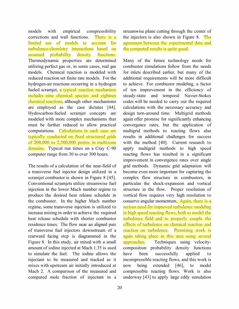
computer range from 30 to over 300 hours.
The results of a calculation of the near-field of
a transverse fuel injector design utilized in a
scramjet combustor is shown in Figure 8 [45].
Conventional scramjets utilize streamwise fuel
injection in the lower Mach number regime to
produce the desired heat release schedule in
the combustor. In the higher Mach number
regime, some transverse injection is utilized to
increase mixing in order to achieve the required
heat release schedule with shorter combustor
residence times. The flow near an aligned pair
of transverse fuel injectors downstream of a
rearward facing step is diagrammed in the
Figure 8. In this study, air mixed with a small
amount of iodine injected at Mach 1.35 is used
to simulate the fuel. The iodine allows the
injectant to be measured and tracked as it
mixes with upstream air initially introduced at
Mach 2. A comparison of the measured and
computed mole fraction of injectant in a
streamwise plane cutting through the center of
the injectors is also shown in Figure 8. The
agreement between the experimental data and
the computed results is quite good.
Many of the future technology needs for
combustor simulations follow from the needs
for inlets described earlier, but many of the
additional requirements will be more difficult
to achieve. For combustor modeling, a factor
of ten improvement in the efficiency of
steady-state and temporal Navier-Stokes
codes will be needed to carry out the required
calculations with the necessary accuracy and
design turn-around time. Multigrid methods
again offer promise for significantly enhancing
convergence rates, but the application of
multigrid methods to reacting flows also
results in additional challenges for success
with the method [40]. Current research to
apply multigrid methods to high speed
reacting flows has resulted in a significant
improvement in convergence rates over single
grid methods. Dynamic grid adaptation will
become even more important for capturing the
complex flow structure in combustors, in
particular the shock-expansion and vortical
structure in the flow. Proper resolution of
vortical flow requires very high resolution to
conserve angular momentum. Again, there is a
serious need for improved turbulence modeling
in high speed reacting flows, both to model the
turbulence field and to properly couple the
effects of turbulence on chemical reaction and
reaction on turbulence. Promising work is
again taking place in this area using several
approaches. Techniques using velocity-
composition probability density functions
have been successfully applied to
incompressible reacting flows, and this work is
now being extended [46], to model
compressible reacting flows. Work is also
underway [43] to apply large eddy simulation
Luo Wenlei
高亮
Luo Wenlei
高亮
Luo Wenlei
高亮
Luo Wenlei
高亮
Luo Wenlei
高亮
Luo Wenlei
高亮

21
(LES) techniques to compressible reacting
flows. Subgrid scale models for the LES of
these flows are currently being developed
using methods previously applied for
modeling the full range of flow scales. Finally,
further work is needed to simplify the
modeling of chemical reaction in combustor
flowfields. Methods for systematically
reducing the number of reactions in a full
reaction mechanism are required to reduce the
computational work [47]. A number of
promising methods are under development.
They were discussed in a previous section.
As with the modeling of inlet flowfields,
experiments are also required to provide data
for the validation of combustor codes. In
addition to the data required for validating inlet
modeling, combustor code validation will
require extensive temperature and species
concentration measurements, as well as the
correlations of these quantities with each other
and with velocity for validation of advanced
turbulence models. Measurements of all of the
required flow variables are more difficult to
obtain in the reacting flow environment of a
scramjet combustor. Significant work will
again be required to develop nonintrusive
diagnostic techniques suitable for making the
required measurements.
The flowfield in the nozzle of a scramjet
engine is characterized by much of the flow
physics of the inlet and combustor, but
additional requirements include the modeling
of:
1. Strong aerodynamic and chemical non-
uniformities.
2. Very high velocities and high
temperatures.
3. Significant divergence and skin friction
losses.
4. Changing thermochemical state.
5. Potential relaminarization of the flow.
6. Energy-bound chemical radicals that
will not relax in the nozzle.
7. Excited vibrational states and their
relaxation.
Computations of nozzle flowfields are usually
conducted with Euler codes or Euler codes
iterated with boundary layer calculations for
initial engineering design studies, and with
either parabolized or full Navier-Stokes codes
for more detailed studies. Steady-state
methods are normally employed. Turbulence
is modeled by algebraic or two-equation
models with empirical compressibility
corrections and wall functions. Perfect gas or,
when necessary, real gas models are used to
determine thermodynamic properties.
Chemical reaction is modeled with reduced
kinetics models as utilized in the upstream
combustor flow. Finite rate analyses are still
required in the nozzle to assess the degree of
reaction that continues to take place and to
determine the extent of recombination
reactions that add to the available thrust.
Calculations for complete nozzles are
typically carried out on structured grids of
100,000 to 500,000 nodes grouped in
multizone domains. Typical run times range
from 1 to 40 hours on a Cray C-90 computer.
The results of a simulation by Sindir to
optimize nozzle performance are given in
Figure 9. A parametric study is performed on
a three-dimensional nozzle using a distribution
of inflow profiles that are given in the figure.
Profiles are characterized in terms of the flow
distortion, given by ep = Pavg/Pmax. Mass and
stream thrust are held constant for all of the
profiles. Simulations using each profile are
conducted using a 3D Euler code. The effects
of the various flow profiles are characterized
Luo Wenlei
高亮
Luo Wenlei
高亮

22
in terms of nozzle efficiency, thrust, and
thrust vector angle. Plots of nozzle efficiency
and thrust vector angle vs. the distortion
parameter are also given in Figure 9. Clearly,
nozzle performance is greatly affected by flow
non-uniformity. Efficiency tends to increase
when the distortion parameter becomes more
negative with increasing pressure toward the
cowl side of the engine. Therefore, high inflow
distortion, oriented appropriately, can
favorably affect nozzle performance.
Future technology needs for nozzle
simulations, even though less demanding,
follow very similar lines to the requirements
for combustor simulations. A factor of five
improvement in the efficiency of the steady-
state Navier-Stokes codes is needed. Dynamic
grid adaptation will also be useful for
capturing shock structure and resolving
possible wall separation due to shock-
boundary layer interactions. There is a need
for improved turbulence models for describing
nozzle flows. Algebraic Reynolds stress
turbulence models offer significant promise for
describing these flowfields [41, 42]. The
reduced kinetics models currently being
applied to nozzle flows appear to be
reasonably accurate, although some further
work to improve the description of
recombination may be warranted. Validation
requirements for nozzle codes are similar to
those required for combustor codes.
Injection and Mixing
The critical issues of fuel injection and mixing
in a scramjet combustor were discussed in this
session by Nejad, Brown, and Dimotakis. A
number of key issues for efficient fuel
injection, mixing and combustion were first
considered. The shear/mixing layer flow was
then discussed to provide a mechanism for a
better understanding of the fundamental
physics of fuel-air mixing and combustion. A
number of conventional fuel injection
strategies were then described followed by
several new less conventional techniques.
Finally, an appraisal of these injection
strategies were made.
There are several key issues that must be
considered in the design of an acceptable fuel
injector. Of particular importance are the total
pressure losses created by the injector and the
injection processes, that must be minimized
since they reduce the thrust of the engine. The
injector design also must produce rapid mixing
and combustion of the fuel and air. Rapid
mixing and combustion allow the combustor
length and weight to be minimized, and they
provide the heat release for conversion to
thrust by the engine nozzle. The fuel injector
distribution in the engine also should result in
as uniform a combustor profile as possible
entering the nozzle so as to produce an
efficient nozzle expansion process. At
moderate flight Mach numbers, up to Mach
10, fuel injection may have a normal
component into the flow from the inlet, but at
higher Mach numbers, the injection must be
nearly axial since the fuel momentum provides
a significant portion of the engine thrust.
Intrusive injection devices can provide good
fuel dispersal into the surrounding air, but
they require active cooling of the injector
structure. The injector design and the flow
disturbances produced by injection also should
provide a region for flameholding, resulting in a
stable piloting source for downstream ignition
of the fuel. The injector cannot result in too
severe a local flow disturbance, that could
result in locally high wall static pressures and
temperatures, leading to increased frictional
losses and strict wall cooling requirements.
Luo Wenlei
高亮
Luo Wenlei
高亮
Luo Wenlei
高亮
Luo Wenlei
高亮
Luo Wenlei
高亮
Luo Wenlei
高亮
Luo Wenlei
高亮
23
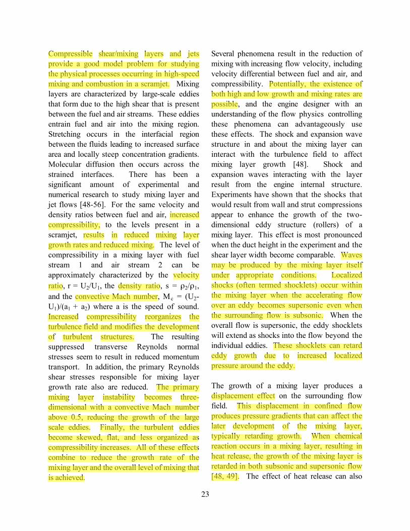
Compressible shear/mixing layers and jets
provide a good model problem for studying
the physical processes occurring in high-speed
mixing and combustion in a scramjet. Mixing
layers are characterized by large-scale eddies
that form due to the high shear that is present
between the fuel and air streams. These eddies
entrain fuel and air into the mixing region.
Stretching occurs in the interfacial region
between the fluids leading to increased surface
area and locally steep concentration gradients.
Molecular diffusion then occurs across the
strained interfaces. There has been a
significant amount of experimental and
numerical research to study mixing layer and
jet flows [48-56]. For the same velocity and
density ratios between fuel and air, increased
compressibility, to the levels present in a
scramjet, results in reduced mixing layer
growth rates and reduced mixing. The level of
compressibility in a mixing layer with fuel
stream 1 and air stream 2 can be
approximately characterized by the velocity
ratio, r = U2/U1, the density ratio, s = ρ2/ρ1,
and the convective Mach number, M c = (U2-
U1)/(a1 + a2) where a is the speed of sound.
Increased compressibility reorganizes the
turbulence field and modifies the development
of turbulent structures. The resulting
suppressed transverse Reynolds normal
stresses seem to result in reduced momentum
transport. In addition, the primary Reynolds
shear stresses responsible for mixing layer
growth rate also are reduced. The primary
mixing layer instability becomes three-
dimensional with a convective Mach number
above 0.5, reducing the growth of the large
scale eddies. Finally, the turbulent eddies
become skewed, flat, and less organized as
compressibility increases. All of these effects
combine to reduce the growth rate of the
mixing layer and the overall level of mixing that
is achieved.
Several phenomena result in the reduction of
mixing with increasing flow velocity, including
velocity differential between fuel and air, and
compressibility. Potentially, the existence of
both high and low growth and mixing rates are
possible, and the engine designer with an
understanding of the flow physics controlling
these phenomena can advantageously use
these effects. The shock and expansion wave
structure in and about the mixing layer can
interact with the turbulence field to affect
mixing layer growth [48]. Shock and
expansion waves interacting with the layer
result from the engine internal structure.
Experiments have shown that the shocks that
would result from wall and strut compressions
appear to enhance the growth of the two-
dimensional eddy structure (rollers) of a
mixing layer. This effect is most pronounced
when the duct height in the experiment and the
shear layer width become comparable. Waves
may be produced by the mixing layer itself
under appropriate conditions. Localized
shocks (often termed shocklets) occur within
the mixing layer when the accelerating flow
over an eddy becomes supersonic even when
the surrounding flow is subsonic. When the
overall flow is supersonic, the eddy shocklets
will extend as shocks into the flow beyond the
individual eddies. These shocklets can retard
eddy growth due to increased localized
pressure around the eddy.
The growth of a mixing layer produces a
displacement effect on the surrounding flow
field. This displacement in confined flow
produces pressure gradients that can affect the
later development of the mixing layer,
typically retarding growth. When chemical
reaction occurs in a mixing layer, resulting in
heat release, the growth of the mixing layer is
retarded in both subsonic and supersonic flow
[48, 49]. The effect of heat release can also
Luo Wenlei
高亮
Luo Wenlei
高亮
Luo Wenlei
高亮
Luo Wenlei
高亮
Luo Wenlei
高亮
Luo Wenlei
高亮
Luo Wenlei
高亮
Luo Wenlei
高亮
Luo Wenlei
高亮
Luo Wenlei
高亮
Luo Wenlei
高亮
Luo Wenlei
高亮
Luo Wenlei
高亮
Luo Wenlei
高亮
Luo Wenlei
高亮
Luo Wenlei
高亮

24
vary spatially as a function of the local
stoichiometry and chemical reaction.
Dimotakis noted that the retarded growth in
both instances can be reversed, however, by
allowing the bounding wall to diverge relative
to the initial wall angles where retarded growth
was noted [50].
Several options are available for injecting fuel
and enhancing the mixing of the fuel and air in
high speed flows typical of those found in a
scramjet combustor. Nejad discussed the two
traditional approaches for injecting fuel include
injection from the combustor walls and in-
stream injection from struts. The simplest
approach for wall injection involves the
transverse injection of the fuel from wall
orifices. Transverse injectors offer relatively
rapid near-field mixing and good fuel
penetration. Penetration of the fuel stream
into the crossflow is governed by the jet-to-
freestream momentum flux ratio. The fuel jet
interacts strongly with the crossflow,
producing a bow shock and a localized highly
three-dimensional flow field. Resulting
upstream and downstream wall flow
separations also provide regions for radical
production and flameholding, but they can also
result in locally high wall heat transfer.
Compressibility effects noted earlier for
mixing layer flows also are evident in the
mixing regime downstream of a transverse jet.
Compressibility again retards eddy growth and
breakup in the mixing layer and suppresses
entrainment of fuel and air, resulting in a
reduction in mixing and reaction. Noncircular
orifice injectors, including elliptical and wedge
shaped [59] cross-sections, produce a weaker
bow shock and reduced separations, resulting
in lower losses and wall heating problems.
The lateral spread of the fuel jet is also
enhanced, and overall mixing is improved,
although there is some reduction in transverse
penetration.
Improved mixing has also been achieved using
alternative wall injector designs. Wall injection
using geometrical shapes that introduce axial
vorticity into the flow field has been
successful. Vorticity can be induced into the
fuel stream using convoluted surfaces or small
tabs at the exit of the fuel injector.
Alternatively, vorticity can be introduced into
the air upstream of the injector using wedge
shaped bodies placed on the combustor walls.
When strong pressure gradients are present in
the flowfield, e.g. at a shock, vorticity aligned
with the flow can be induced at a fuel-air
interface, where a strong density gradient
exists, by virtue of the baroclinic torque. Fuel
injection ramps have proven to be an effective
means for fuel injection in a scramjet engine.
Two ramp injector schemes are diagrammed in
Figures 10 a & b. Fuel is injected from the
base of the ramp. The unswept ramp
configuration provides nearly streamwise
injection of fuel to produce a thrust
component. Flow separation at the base of
the ramp provides a region for flame holding
and flame stabilization through the buildup of
a radical pool. The ramp itself produces
streamwise vorticity as the air stream sheds
off of its edges, improving the downstream
mixing. The swept ramp design provides all of
the features of the unswept ramp, but the
sweep results in better axial vorticity
generation and mixing. A novel variation on
the swept wedge injector, termed the aero-
ramp injector, is also shown in Figure 10c. It
utilizes three arrays of injector nozzles at
various inclination and yaw angles to
approximate the physical swept ramp design.
The aero-ramp injector has many of the
features of the swept ramp design without the
losses associated with an intrusive device. A
comparison of the two injectors is given in
Luo Wenlei
高亮
Luo Wenlei
高亮
Luo Wenlei
高亮

25
Figure 11, where transverse fuel penetration,
lateral spread, plume area, and mass fraction
decay are shown. While transverse
penetration and plume area are reduced with
the aero-ramp, lateral spread and mass fraction
decay are nearly the same as those for the
swept ramp injector.
In-stream injection also has been utilized for
fuel injection in a scramjet. Traditional
approaches involve fuel injection from the
sides and the base of an instream strut.
Transverse injection results in behavior
identical to transverse fueling from the wall.
Injection from the base of the strut results in
slower mixing as compared to transverse
injection. A combination of transverse and
streamwise injection, varied over the flight
Mach number range, often has been utilized to
control reaction and heat release in a scramjet
combustor. As noted earlier, however,
streamwise injection has the advantage of
adding to the thrust component of the engine.
To increase the mixing from streamwise
injectors, many of the approaches utilized to
improve wall injection, including noncircular
orifices, tabs, and ramps, have been utilized
successfully. Several new concepts have
emerged as well. Pulsed injection using either
mechanical devices or fluidic oscillation
techniques have shown promise for improved
mixing. A fluidic approach using a Hartmann-
Sprenger tube, shown schematically in Figure
12a, offers a possible means of producing a
rapid pressure oscillation with large amplitude
by means of a geometrically simple device.
Fuel injection schemes integrated with cavities
also provide the potential for improved mixing
and flameholding. One possible design is
shown in Figure 12b. This integrated fuel
injection/flameholding device, utilizing fuel
injection into a cavity and from its base,
integrates the fuel injection with a cavity that
provides flameholding, flame stabilization, and
mixing enhancement if the cavity is properly
tuned.
Even with these results regarding the behavior
of mixing layer flows and a number of
techniques for enhancing fuel-air mixing, a
number of issues remain to be studied. Indeed,
a controversy still exists that questions
whether fuel-air mixing will even be a problem
in a scramjet engine in flight. The issue is
whether or not the turbulence present in the
atmosphere and ultimately present in the inlet
flow will provide sufficient turbulent mixing of
fuel and air in the combustor. Since all of the
work to study high-speed mixing flows has
been conducted (or simulated) using a different
(earth bound) environment, the need for
enhanced mixing still remains unresolved.
Concluding Remarks
The presentations and discussion periods of
the workshop resulted in a number of
interchanges between engine developers and
members of the associated research
community that provided a better
understanding of the efforts in each topical
area, in keeping with the workshop objectives.
The status of the overall engineering effort was
described, as were critical needs for successful
extensions.
The status of current research in supersonic
mixing and combustion was described to the
engineering community. A number of plans
for future research were discussed. In many
instances, the current work and future research
plans were consistent with the engineering
needs. In other instances, however, needs
became apparent that are not being addressed
directly.
While the procedures for engine design are well
Luo Wenlei
高亮
Luo Wenlei
高亮
Luo Wenlei
高亮
Luo Wenlei
高亮
Luo Wenlei
下划线
Luo Wenlei
下划线
Luo Wenlei
高亮
Luo Wenlei
高亮
Luo Wenlei
下划线
Luo Wenlei
下划线
Luo Wenlei
下划线
Luo Wenlei
高亮
Luo Wenlei
高亮
Luo Wenlei
高亮
Luo Wenlei
高亮
Luo Wenlei
下划线
26
established and fruitful, the inability to make
the all of the necessary measurements clearly
necessitates further work to develop additional
measurement and diagnostic tools.
Measurement sensitivities for several critical
engine parameters are given in Table 5.
Weaknesses requiring improved measurement
techniques and devices are also pointed out in
the table. Accurate in-stream measurements of
velocity, temperature, pressure, and chemical
species in engine flow fields using nonintrusive
diagnostics are also critical to develop a
successful engine design. A summary of
diagnostic capabilities for laser-based
instrumentation applied to scramjet testing is
given in Table 6. The problems for each
approach described in the Table must be
resolved, or new methods must be developed
where necessary. Future approaches must be
based on inexpensive and robust technologies,
and the resulting instrumentation must be
useful in hostile testing environments.
Simulation and modeling capabilities must be
extended to allow more routine application to
realistic engine geometries. An order of
magnitude increase in computational speed
must be achieved before engine design codes
can meet this challenge. Multigrid methods
appear to be one approach for achieving this
goal, but significant work is needed before
applying this method to high-speed reacting
flows. Improving computer architectures,
particularly parallel processors, also will
provide some of the needed enhancement.
Turbulence modeling also requires significant
work. Research is needed not only to improve
the capability for modeling the flowfield
turbulence, but also to describe the interaction
of turbulence with chemistry in a compressible
reacting flow. For the analysis of engine
component flows, large eddy simulation may
provide a means for computing (rather than
modeling) a larger proportion of the scale of
the flow. To model chemical reaction of fuel
and air in an engine, reduced kinetic models
must be developed to reduce computational
time required for solving the species equations,
particularly for hydrocarbon fuels. To
support hydrocarbon-based scramjet engine
development, a comprehensive data base for
C7 - C12 aliphatic fuel components under
scramjet conditions should be developed. In
addition, surrogate hydrocarbon fuels should
be selected based upon available information
about endothermic behavior and catalysis.
And finally, the aliphatic fuels data base
should be utilized to derive suitable starting
and reduced mechanisms for candidate fuels.
Several approaches for fuel injection in the
combustor were discussed. Designs utilizing
geometries or flow alterations that induce
streamwise vorticity to enhance mixing appear
to be most promising. Losses induced by the
injection process reduce the efficiency of the
injector in most designs, however. Future
work to optimize the injector design for
maximum mixing enhancement with minimum
losses will be needed. Work to relate findings
from simulations or ground based testing to
actual conditions in flight should be included.
Issues regarding the thermochemical and
transport behavior of the fuels were also
raised. A better understanding of the state of
hydrocarbon fuels as their temperature
increases in vehicle cooling passages is
important for design. Changes in the state of
the fuel can affect the reactivity of the fuel and
the resulting combustion efficiency
significantly. There is a lack of understanding
of the physical processes that may contribute
to these effects. To understand these
phenomena, changes in the fuel state must be
studied in a realistic simulation of the scramjet
Luo Wenlei
下划线
Luo Wenlei
高亮
Luo Wenlei
高亮
Luo Wenlei
高亮
Luo Wenlei
下划线
Luo Wenlei
下划线
Luo Wenlei
下划线
Luo Wenlei
下划线
Luo Wenlei
高亮
Luo Wenlei
高亮
Luo Wenlei
高亮

27
preheating and combustion processes. A co-
annular or opposed-jet burner that would burn
hot, partially reacted fuels represents one
possible relevant experiment for such studies.
Traditional premixed combustion devices
appear to be inadequate to address the
important issues.
Acknowledgment
The authors wish to thank all of the
participants in the workshop for volunteering
to attend and for their valuable contributions
to the discussions. The authors especially
express their gratitude to the presenters at the
workshop, not only for the presentations, but
also for their comments to improve our
attempts to summarize their thoughts in this
paper.
References
1. Billig, F. S. "Propulsion Systems From
Takeoff to High Speed Flight," Reprint from
High-speed Flight Propulsion System, Vol.
137 of Progress in Astronautics and
Aeronautics, AIAA.
2. Kay, I. W. et al., "Hydrocarbon Fueled
Scramjet, Vol. VIII, Piloting and Flame
Propagation Investigation," AFAPL TR 68-
146, May 1971.
3. Heins, A. E., et al., "Hydrocarbon
Scramjet Feasibility Program Part III. Free Jet
Engine Design and Performance," AFAPL
TR-74, Jan 1971.
4. Billig, F. S., "Combustion Processes in
Supersonic Flow," Journal of Propulsion and
Power, Vol. 4, May-June 1988, pp. 209-216.
5. Burnette, T. D., "Dual Mode Scramjet,"
The Marquardt Corporation, AFAPL-TR-67-
132, June 1968.
6. Harshman, D. L., "Design and Test of a
Mach 7 - 8 Supersonic Combustion Ramjet
Engine," AIAA Propulsion Specialist Meeting,
July 1967, Washington, DC.
7. Billig, F. S., “Research in Supersonic
Combustion,” AIAA Paper 92-0001, Jan 1992
8. Anderson, G. Kumar, A., and Erdos, J.
“Progress in Hypersonic Combustion
Technology with Computastion and
Experiment,” AIAA Paper 90-5254, Oct.
1990.
9. Voland, R. and Rock, K., “Concept
Demostration Engine and Subscale Parametric
Engine Tests,” AIAA Paper 95-6055, April
1995.
10. Stevens, R. Thompson, M. W., “Steam
Calorimetry Uncertainty Analysis for Direct-
Connect Arc Tunnel Combustor tests, GWP #
107A,” APL-NASP-94-016, Jan. 1995
11. JANNAF Ramjet Subcommittee
Workshop, "Fuels for Future High-Speed
Flight Vehicles," CPIA Publication 518 (2
vol.), June 1988.
12. Northam, G. B., ed., "Workshop
Report: Combustion in Supersonic Flow,"
22nd JANNAF Combustion Meeting
Proceedings, CPIA Publication 432, Vol. 1,
1985.
13. Beach, H. L., "Supersonic Combustion
Status and Issues," in Major Research Topics
in Combustion, Hussaini, Kumar, and Voigt,
eds, Springer Verlag, NY, 1992.
14. Heiser, W. H., Pratt, D. T., Hypersonic
Airbreathing Propulsion, AIAA.
Luo Wenlei
高亮

28
15. Murthy, S. N. B., and Curran, E. T.,
eds, High-Speed Flight Propulsion Systems,
AIAA Progress in Astronautics and
Aeronautics, Vol. 137, AIAA, 1991.
16. Sobel, D. R., and Spadaccini, L. J.,
"Hydrocarbon Fuel Cooling Technologies for
Advanced Propulsion," ASME-95-GT-226,
June 1995.
17. New World Vistas, Air and Space
Power for the 21st Century, Aircraft and
Propulsion Volume, 1996.
18. Ianovski, L. S., "Endothermic Fuels for
Hypersonic Aviation," Symposium on Fuels
and Combustion Technology for Advanced
Aircraft Engines, AGARD-CP-536, pp. 44-1
to 44-8, Sept. 1993.
19. Ianovski, L., Sapgir, G., "Heat and
Mass Transfer to Hydrocarbon Fuels at
Thermal Decomposition in Channels of
Engines," AIAA Paper 96-2683, July, 1996.
20. Lander, H., Nixon, A. C., "Endothermic
Fuels for Hypersonic Vehicles," Journal of
Aircraft, Vol. 8, No. 4, pp. 200-207, 1971.
21. Favorskii, O. N., Kurziner, R. I.,
"Development of Air-Breathing Engines for
High Speed Aviation by Combining Advances
in Various areas of Science and Engineering,"
High Temperature (translation of Teplofizika
Vysokikh Temperature), Vol. 28, No. 4, pp.
606-614, 1990.
22. Warnatz, J., "Rate Coefficients in the
C/H/O System," in Combustion Chemistry,
W. C. Gardiner, ed., Springer Verlag, New
York, pp. 197-360, 1984.
23. Spadaccini, L. J., Colket, M. B.,
"Ignition Delay Characteristics of Methane
Fuels," Prog. Energy Combust. Sci., Vol. 20,
pp. 431-460, 1994.
24. Faith, L. E., Ackerman, G. H., Heck, C.
K., Henderson, H. T., Ritchie, A. W. Ryland,
L. B., "Hydrocarbon Fuels for Advanced
Systems," AFAPL-TR-70-71, Dec. 1971.
(AIAA Journal, Vol. 4, pp. 513-520, 1966).
25. Edwards, T., "Recent Research Results
in Advanced Fuels," ACS Petroleum
Chemistry Division Preprints, Vol. 41, No. 2,
pp. 481-487, 1996.
26. Savage, P. E., et al, "Reactions at
Supercritical Conditions: Applications and
Fundamentals," AIChE Journal, Vol. 41(7),
pp. 1723-1778, 1995.
27. Dardas, Z., et al, "High-Temperature,
High-Pressure in Situ Reaction Monitoring of
Heterogeneous Catalytic Processes under
Supercritical Conditions by CIR-FTIR," J.
Catalysis, Vol. 159, pp. 204-211, 1996.
28. Pellett, G. L., Northam, G. B., Wilson,
L. G., "Counterflow Diffusion Flames of
Hydrogen, and Hydrogen Plus Methane,
Ethylene, Propane, and Silane, vs Air: Strain
Rates at Extinction," AIAA Paper 91-0370,
Jan. 1991.
29. Edwards, T., "USAF Supercritical
Hydrocarbon Fuels Interests", AIAA Paper
93-0807, January 1993.
30. Chen, L.-D., Sui, P.-C., "Atomization
During the Injection of Supercritical Fluid Into
High Pressure Environment," paper presented
at 1994 IUTAM on Droplets and Sprays, 6-
10 Dec. 1994, Tainan, Taiwan.

29
31. Petley, D. H., Jones, S. C., “Thermal
Management for a Mach 5 Cruise Aircraft
Using Endothermic Fuel,” Journal of Aircraft,
Vol. 29(3), pp. 384-389, 1992.
32. Pegg, R. J., Hunt, J. L., Petley, D. H.,
“Design of a Hypersonic Waverider-Derived
Airplane,” AIAA Paper 93-0401, 1993.
33. Egolfopoulos, F. N. and Law, C.K.,
“Chain mechanisms in the Overall Reaction
Orders in Laminar Flame Propagation,”
Combustion and Flame, Volume, 80, pp. 7-16,
1990.
34. Peters, N., “Numerical and Asymptotic
Analysis of Systematically Reduced Reaction
Schemes for Hydrocarbon Flames,” Numerical
Simulation of Combustion Phenomena,
Lecture Notes in Physics, Vol. 241, pp. 90-
109, 1985.
35. Lam, S. H., “Reduced Chemistry
Modeling and Sensitivity Analysis,” 1994-
1995 Lecture Series: Aerothermochemistry for
Hypersonic Technology, Von Karman
Institute for Fluid Dynamics, 1995.
36. Chelliah, H. et al., “Reduced Kinetic
Mechanisms for Application in Combustion
Systems,” Peters and Rogg, editors, Springer
Verlad, 1993.
37. Pope, S. B., “Computationally Efficient
Implementation of Combustion Chemistry
Using In-Situ Adaptive Tabulation,” Cornell
University Report FDA 96-02, 1996.
38. Eckbreth, A.C., Laser Diagnostics for
Combustion Temperature and Species, Second
Edition. Combustion science and Technology
Book Series, Vol. 3, Gordon and Breach
Publishers, SA, 1996.
39. Hanson, R. K., “Combustion
Diagnostics: Planar Flowfield Imaging,”
Twenty First Symposium (International) on
Combustion, The Combustion Institute, pp.
1677-1691, 1986.
40. Edwards, J. R., “Development of an
Upwind Relaxation Multigrid Method for
Computing Three-Dimensional Viscous
Internal Flows,” AIAA Paper 95-0208, Jan.
1995.
41. Adumitroaie, V., Colucci, P. J., Taulbee,
D. B., and Givi, P., “LES, DNS and RANS for
the Analysis of High-Speed Turbulent
Reacting Flows,” Annual Report, NASA
Grant NAG 1-1122, 1994.
42. Girimaji, S. S., Galilean, A., “Invariant
Explicit Algebraic Reynolds Stress Model for
Curved Flows,” NASA CR-198340, pp. 1-28
June 1996.
43. Colucci, P. J., Jaberi, F. A., Givi, P.,
and Pope, S. B., “Filtered Density Function
for Large Eddy Simulation of Turbulent
Reacting Flows,” Submitted for publication,
Physics of Fluids.
44. Jachimosksi, C. J., “An Analytical
Study of the Hydrogen-Air Reaction
Mechanism with Application to Scramjet
Combustion,” NASA TP-2791, Feb. 1988.
45. Eklund, D. R., Northam, G. B., and
Hartfield, R. J., “A Detailed Investigation of
Staged Norman Injection into a Mach 2 Flow,”
Proceedings of the 27th JANNAF
Combustion Meeting, Cheyenne, Wyoming,
Nov. 5-9, 1990.
46. Delarue, B. J., and Pope, S. B.,

30
“Application of PDF Methods to
Compressible Turbulent Flows,” Submitted
for publication, Physics of Fluids.
47. Mass, U., and Pope, S. B., “Simplifying
Chemical Kinetics: Intrinsic Low-Dimensional
Manifolds in Composition Space,”
Combustion and Flame, V. 88, pp. 239-264,
1992.
48. Dimotakis, P. E., “Turbulent Free Shear
Layer Mixing and Combustion,” High Speed
Flight Propulsion Systems, Chapter 7,
Progress in Astronautics and Aeronautics, vol.
137, 1991.
49. Drummond, J. P., Carpenter, M. H.,
and Riggins, D. W., “Mixing and Mixing
Enhancement in High Speed Reacting Flows,
High Speed Flight Propulsion Systems,”
Chapter 7, Progress in Astronautics and
Aeronautics, vol. 137, 1991.
50. Givi, P., and Riley, J. .J., “Some
Current Issues in the Analysis of Reacting
Shear Layers: Computational Challenges,”
Major Research Topics in Combustion,
Editors: M. Y. Hussaini, A. Kumar and R. G.
Voigt, pp. 588-650, Springer-Verlag, New
York, NY,
1992.
51. Drummond, J. P., and Givi, P.,
“Suppression and Enhancement of Mixing in
High-Speed Reacting Flow Fields,”
Combustion in High-Speed Flows, pp. 191-
229, Editors: J. Buckmaster, T.L. Jackson and
A. Kumar, Kluwer Academic Publishers,
Boston, MA, 1994.
52. Goebel, S. G., and Dutton, J. C.,
“velocity Measurements of Compressible,
Turbulent Mixing Layers,” AIAA Paper 90-
0709, January 1990.
53. Smith, S. H., Lozano, A., Mungal, M.
G., and Hanson, R. K., “Scalar Mixing in the
Subsonic Jet in Crossflow.” AGARD
Computational and Experimental Assessment
of Jets in Crossflow, Winchester, pp. 6.1-
6.13, 1993.
54. Hall, J. L., Dimotakis, P. E., and
Rosemann, H. “Experiments in Non-reacting
Compressible Shear Layers,” AIAA Paper 91-
0629, January 1991.
55. Samimy, M., Zaman, K. B. M .Q., and
Reeder, M. F., “Effect of tabs on the Flow and
Noise Field of an Axisymmetric jet,” AIAA
Journal, Vol. 31, No. 4, pp. 609-619, 1993.
56. Cox, S. K., Fuller, R. P., Schetz, J. A.,
and Walters, R. W., “Vortical interactions
Generated by an Injector Array to Enhance
Mixing in Supersonic Flow” AIAA Paper 94-
0708, January 1994.
Appendix A
Research Problems for Future Work
• Affordability - minimize weight,size,complexity, part count for a givenmission profile
• Methodology for optimization
• Materials and structures
– scaling of leading edges tominimize drag
– “cheating” by injecting liquid,ablating, etc.
• Inlet design
• Fuel characterization
• Unsteadiness
• Fuel injection and mixing
Luo Wenlei
高亮

31
• Recovery of kinetic energy to producethrust
GROUND BASED TESTING
• Influence of contaminants on ignition-vitiation; combustion and expansionbesides ignition; effects on radiation
• Turbulence - no current data
• Nonequilibrium
• Boundary layer effects
• Scaling to flight conditions
• Complementary experimental programfor relevant phenomena
• Utilization of pulsed facilities
− elimination of vitiation effects
FUELS AND FUEL SYSTEMS
• Experimental program to determineenergy yields of fuels
• Creation of kinetics data base for long-term use
• Low temperature starting and pilotingsystems
– trimethyl Al additives
– GASL micro rocket
– plasma torch
– embedded ramjets
– gelled fuels (GASL)
• Improvement of fuel specific ...
• Nano particle carbon particles
• Micro encapsulated fuels
INJECTION AND MIXING
• Exploitation of longitudinal vorticity formixing enhancement
• Interaction between injectors
• Minimization of losses
• Thermodynamic state of fuel at injection
• Cold flow studies?
• Curvature-induced Rayleighdestabilization; role of pre-existingturbulence
• Systems studies to optimize, but notnecessarily minimize, losses
• German-Russian work on three injectorclasses-micro pylons
• Relationship to flame holding
COMBUSTION CHEMISTRY
• Compile and validate kinetic data base atthree levels
– detailed
– skeletal
– reduced
• Ignition enhancers
• Liquid-phase kinetics; supercriticalkinetics
• Recombination kinetics
– catalytic additives
• Role of soot
• Combustion at high strain rates
• Unsteadiness
• Incorporating kinetics mechanisms indesign codes
• Development of subscale experiments
– Russian results by Baev?
– opposed jet burner?
DIAGNOSTICS
• Skin friction measurements
• Heat flux measurements, includingradiation
• Detailed measurements of boundary andinitial conditions
• Application of non-intrusiveinstrumentation to free jet tests
• Measurement of velocity profiles
• Determination of measurementuncertainties
Luo Wenlei
高亮

32
• Turbulence intensity levels(concentration in supersonic flow)
• Instantaneous measurements todetermine turbulence-chemistryinteractions
• Pressure-sensitive paint to measuresurface pressures
• Mapping of total pressure and totaltemperature
• Design of well-posed experiment
• Concentration measurements
– mean and fluctuating
– spectrally resolved
SIMULATION
• Stochastic models
• Sensitivity to unsteadiness
• Algebraic closure models
– stress
– scalar flux
• Solvers for particle methods
– improved efficiency
• Well-posed validation experiment
• Preprocessing
– adaptive gridding
• Solvers
– increased efficiency (factor of 10)
– provisions for real time (dynamic)grid adaptation
– domain and functiondecomposition capability formassively parallel and/ornetworked computers
• Physical models
– turbulence/chemistry interactionmodels
– testing of higher orderphenomenological turbulencemodels
– assessment of LES techniques forrealistic geometries and flowconditions
– testing of fast reduced kineticsmechanisms
BILLIG’S COMMENTS
• Inlets-Isolators
– streamline tracing
– analogy between C-I-I &aerodynamic phenomena
– shear high temperature reduction
– sweep
– starting
• Fuels
– densification
– additives
– storability
– toxicity
– rheology
• Fuel Preparation
– heat pipes (open-closed)
– plasma generators
• Injection - Mixing
– subsonic imbedded zones(cavities, steps, bases)
• Ignition
− radical generators
• Combustion-Combustors
– physical vs. thermal throats
– shear, high temperature
– recombination kinetics
– transpiration
• Nozzles
– shear, high temperature
– recombination
– exploitation of non-uniformentrance flow
Luo Wenlei
高亮
Luo Wenlei
高亮
Luo Wenlei
高亮
Luo Wenlei
高亮
Luo Wenlei
高亮
Luo Wenlei
高亮
Luo Wenlei
高亮
Luo Wenlei
高亮
Luo Wenlei
高亮
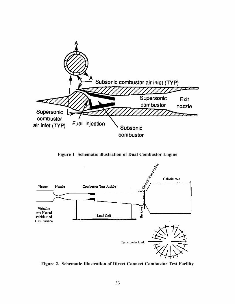
33
Figure 1 Schematic illustration of Dual Combustor Engine
Figure 2. Schematic Illustration of Direct Connect Combustor Test Facility
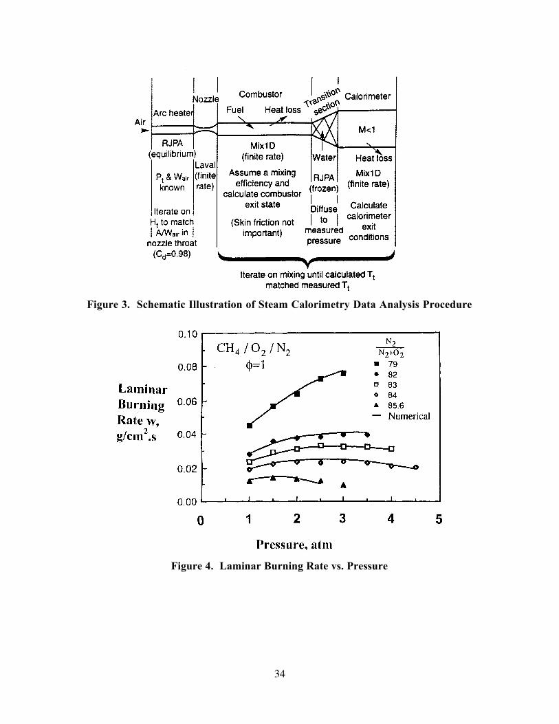
34
Figure 3. Schematic Illustration of Steam Calorimetry Data Analysis Procedure
Figure 4. Laminar Burning Rate vs. Pressure
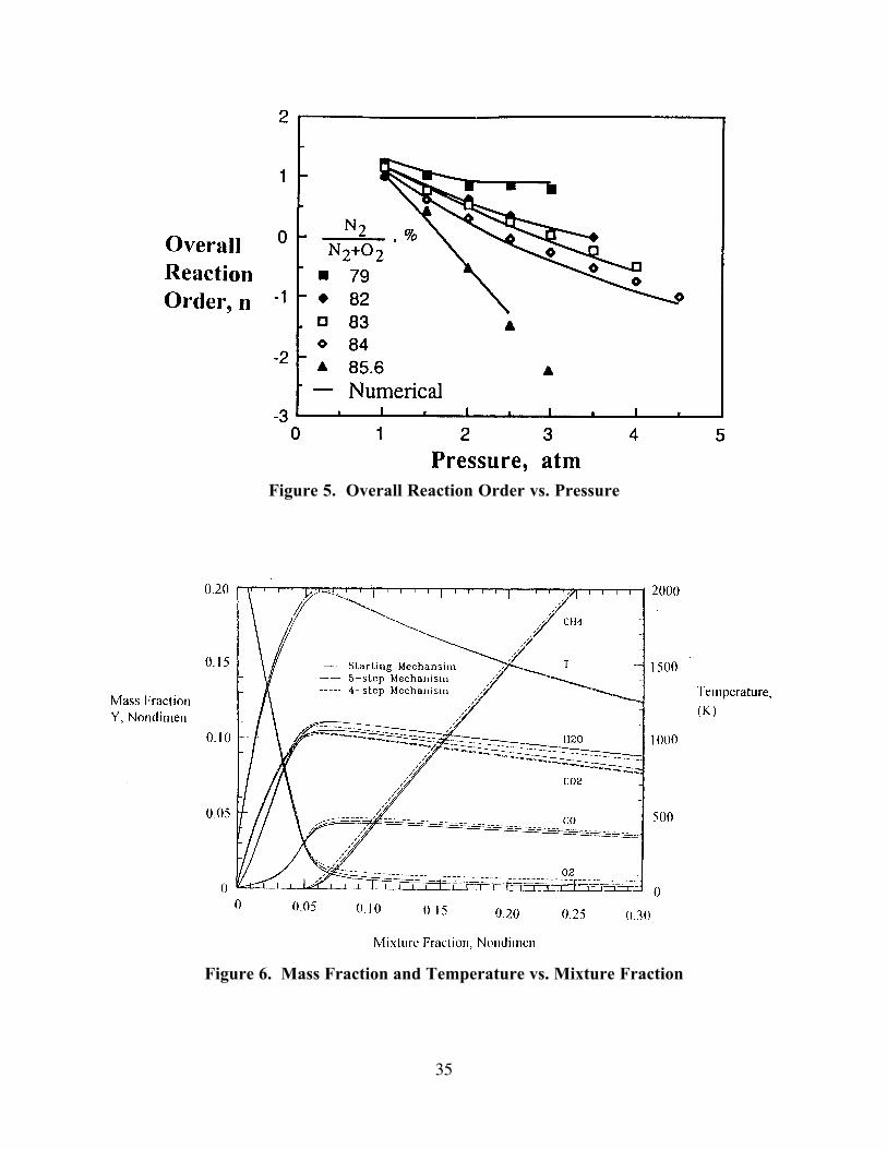
35
Figure 5. Overall Reaction Order vs. Pressure
Figure 6. Mass Fraction and Temperature vs. Mixture Fraction
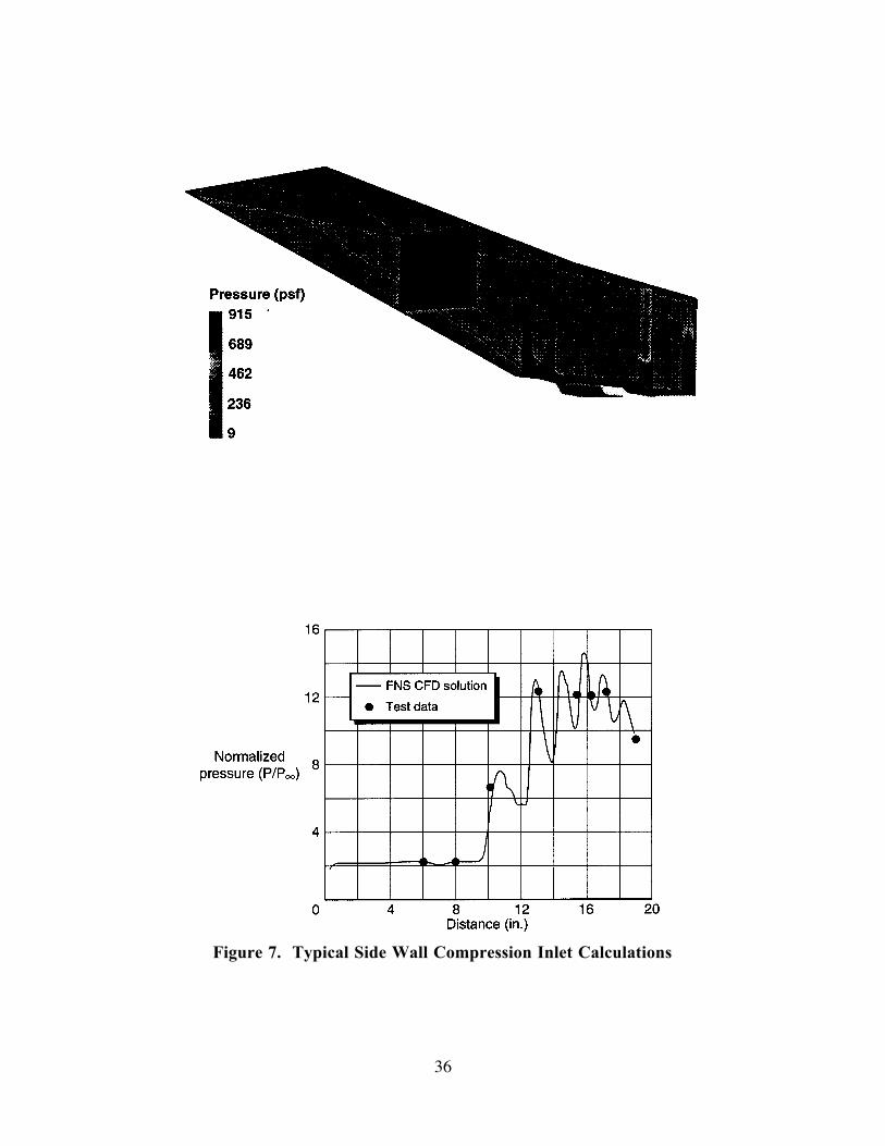
36
Figure 7. Typical Side Wall Compression Inlet Calculations
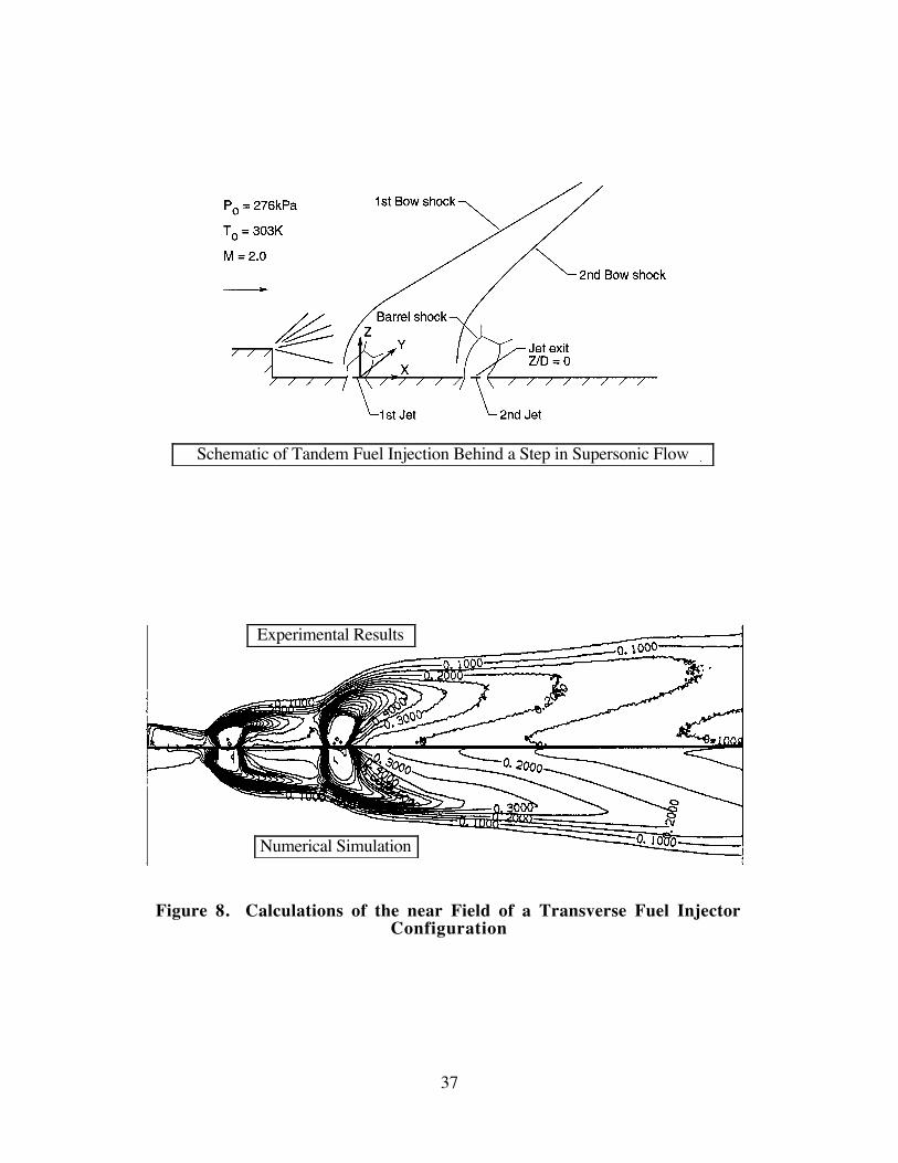
37
Figure 8. Calculations of the near Field of a Transverse Fuel InjectorConfiguration
Numerical Simulation
Experimental Results
Schematic of Tandem Fuel Injection Behind a Step in Supersonic Flow

38
Figure 9. Optimization of Nozzle Performance Based on Nozzle Inflow Profiles
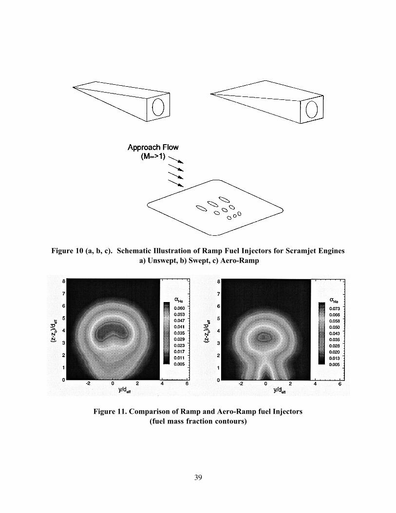
39
Figure 10 (a, b, c). Schematic Illustration of Ramp Fuel Injectors for Scramjet Engines
a) Unswept, b) Swept, c) Aero-Ramp
Figure 11. Comparison of Ramp and Aero-Ramp fuel Injectors
(fuel mass fraction contours)
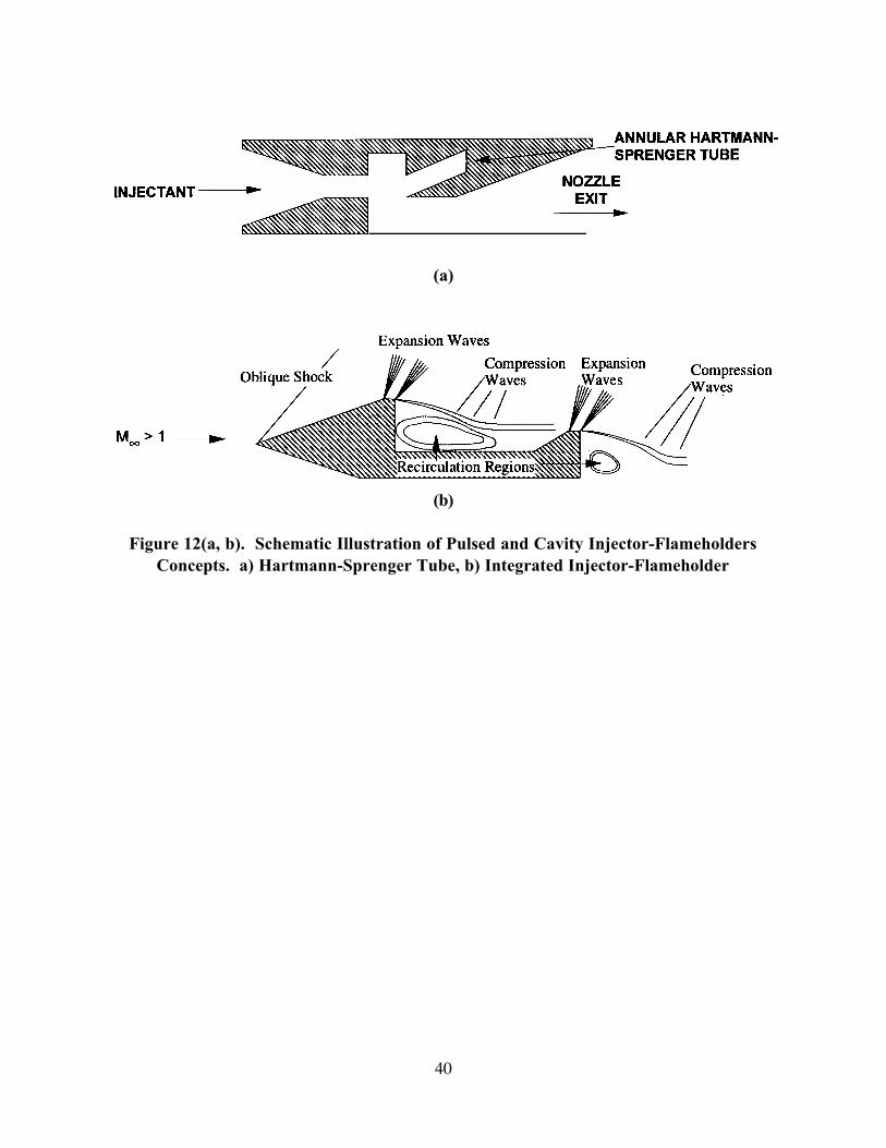
40
(a)
(b)
Figure 12(a, b). Schematic Illustration of Pulsed and Cavity Injector-Flameholders
Concepts. a) Hartmann-Sprenger Tube, b) Integrated Injector-Flameholder