Futaba - largest U.S. distributor of radio-control and...
26
Futaba DIGITAL PROPORTIONAL RADIO CONTROL FP-7UAP PCM 1024 SYSTEM FP-7UAF FM SYSTEM D60460
Transcript of Futaba - largest U.S. distributor of radio-control and...
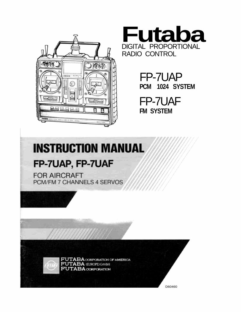
FutabaDIGITAL PROPORTIONALRADIO CONTROL
FP-7UAPPCM 1024 SYSTEM
FP-7UAFFM SYSTEM
D60460
Thank you for purchasinga Futaba digital proportional radio control set.
Please read this manualcarefully before using your setThe last page of this manual
is a double foldout showing the nameof each part of the transmitter.
Please open it when reading this manual.
foldout
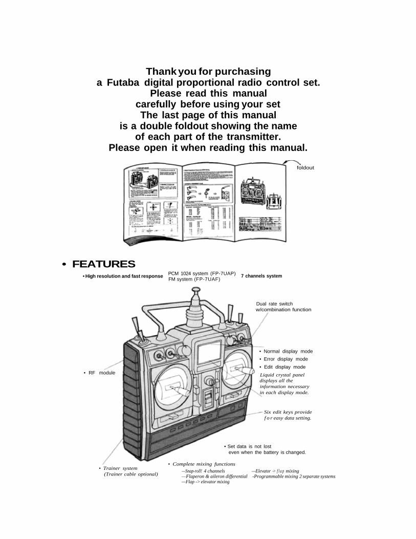
• FEATURES• High resolution and fast response PCM 1024 system (FP-7UAP)
FM system (FP-7UAF)7 channels system
Dual rate switchw/combination function
• RF module
• Trainer system(Trainer cable optional)
• Normal display mode
• Error display mode
• Edit display mode
Liquid crystal paneldisplays all theinformation necessaryin each display mode.
Six edit keys providef o r easy data setting.
• Complete mixing functions
—Snap-roll! 4 channels —Elevator -> f l a p mixing—Flaperon & aileron differential -Programmable mixing 2 separate systems—Flap -> elevator mixing
• Set data is not losteven when the battery is changed.

• TABLE OF CONTENTS
SET CONTENTS . . . . . . . . . . . . . . . . . . . . . . . . . . . . . . . . . . . . . . . . . . . 2BEFORE USING . . . . . . . . . . . . . . . . . . . . . . . . . . . . . . . . . . . . . . . . . . 3-5DISPLAY FUNCTIONS
NORMAL DISPLAY MODE . . . . . . . . . . . . . . . . . . . . . . . . . . . . . . 6ERROR DISPLAY MODE . . . . . . . . . . . . . . . . . . . . . . . . . . . . . . . . 7EDIT DISPLAY MODE . . . . . . . . . . . . . . . . . . . . . . . . . . . . . . . . . . 7
FUNCTIONS AND DATA SETTINGADJUSTABLE TRAVEL VOLUME . . . . . . . . . . . . . . . . . . . . . . . . 8DUAL RATE . . . . . . . . . . . . . . . . . . . . . . . . . . . . . . . . . . . . . . . . . . 8E X P O N E N T I A L . . . . . . . . . . . . . . . . . . . . . . . . . . . . . . . . . . . . . . . . 9REVERSE . . . . . . . . . . . . . . . . . . . . . . . . . . . . . . . . . . . . . . . . . . . . 9FAIL SAFE . . . . . . . . . . . . . . . . . . . . . . . . . . . . . . . . . . . . . . . . . . . 10PROGRAMMABLE MIXING 1 . . . . . . . . . . . . . . . . . . . . . . . . . . . . 11PROGRAMMABLE MIXING 2 . . . . . . . . . . . . . . . . . . . . . . . . . . . . 12ELEVATOR -> FLAP MIXING . . . . . . . . . . . . . . . . . . . . . . . . . . . . 13FLAP -> ELEVATOR MIXING . . . . . . . . . . . . . . . . . . . . . . . . . . . . 14SNAP-ROLL . . . . . . . . . . . . . . . . . . . . . . . . . . . . . . . . . . . . . . . . . . 15AILERON DIFFERENTIAL . . . . . . . . . . . . . . . . . . . . . . . . . . . . . . 16FLAPERON . . . . . . . . . . . . . . . . . . . . . . . . . . . . . . . . . . . . . . . . . . . 17FLAP TRIM . . . . . . . . . . . . . . . . . . . . . . . . . . . . . . . . . . . . . . . . . . . 18SUB T R I M . . . . . . . . . . . . . . . . . . . . . . . . . . . . . . . . . . . . . . . . . . . . . 18
COMBINATION SWITCH . . . . . . . . . . . . . . . . . . . . . . . . . . . . . . . . 18MODULATION . . . . . . . . . . . . . . . . . . . . . . . . . . . . . . . . . . . . . . . . 19
OTHER FUNCTIONS . . . . . . . . . . . . . . . . . . . . . . . . . . . . . . . . . . . . 19-20USING THE ACCESSORIES . . . . . . . . . . . . . . . . . . . . . . . . . . . . . . . 20-21NOMENCLATURE (DOUBLE FOLDOUT) . . . . . . . . . . . . . . . . . . . . . . 22SERVO EXPLODED VIEW . . . . . . . . . . . . . . . . . . . . . . . . . . . . . . . . . . . 23
ABBREVIATIONS
ATV ADJUSTABLE TRAVEL FLPR FLAPERONVOLUME FLTR FLAP TRIM
D/R DUAL RATE STRM SUB TRIMEXP EXPONENTIAL COMB COMBINATION SWITCHREV REVERSE MOD MODULATIONF/S FAILSAFE AUX AUXILIARYPMX PROGRAMMABLE MIXING PCM PULSE CODE MODULATI2 ->6 ELEVATOR^ FLAP MIXING PPM PULSE POSITION6 - > 2 FLAP -> ELEVATOR MIXING MODULATIONSNP SNAP-ROLL B.F/S BATTERY FAIL SAFEDIFF AILERON DIFFERENTIAL
— 1 —
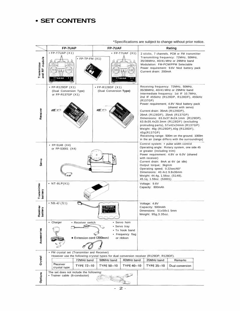
• SET CONTENTS
*Specifications are subject to change without prior notice.
FP-7UAP FP-7UAF Rating• FP-T7UAP ( X 1 ) • FP-T7UAF (X1) 2 s t icks , 7 channels, PCM or FM transmitter
Transmitting frequency: 72MHz, 50MHz,35/36MHz, 40/41 MHz or 29MHz bandModulation: FM-PCM/PPM SelectablePower requirement: 9.6V Nicd battery packCurrent drain: 200mA
• FP-TP-FM (X1)
• FP-R129DP (X1)(Dual Conversion Type)or FP-R137GP (X1)
• FP-R128DF (X1)(Dual Conversion Type)
Receiving frequency: 72MHz, 50MHz,35/36MHz, 40/41 MHz or 29MHz bandIntermediate frequency: 1st IF 10.7MHz,2nd IF 455kHz (R129DP, R128DF), 455kHz(R137GP)Power requirement; 4.8V Nicd battery pack
(shared with servo)Current drain: 35mA (R129DP),
26mA (R128DF), 25mA (R137GP)Dimensions: 63.0x37.8x24.1mm (R129DP).63.8x35.4x20.3mm (R128DF) (excludingprotruding parts), 57x42x24mm (R137GP)Weight: 45g (R129DP),40g (R128DF),45g(R137GP)Receiving range: 500m on the ground. 1000min the air (range differs with the surroundings]
Control system: + pulse width controlOperating angle: Rotary system, one side 45or greater (including trim)Power requirement: 4.8V or 6.0V (sharedwith receiver)Current drain: 8mA at 6V (at idle)Output torque; 3kg/cmOperating speed; 0.22sec/60°Dimensions: 40.4x1 9.8x36mmWeight: 44.4g, 1.56oz. (S148),45.1q, 1.59oz. (S3001)
Voltage: 9.6VCapacity: 800mAh
Voltage: 4.8VCapacity: 500mAhDimensions: 51x58x1 5mmWeight: 95g,3.35oz.
• FP-S148 (X4)or FP-S3001 (X4)
• NT-8LP(X1)
• NR-4J (X1)
• Charger • Receiver switch • Servo horn
• Servo tray
• Tx hook band
• Frequency flagor ribbon
• FM crystal set (Transmitter and Receiver)However use the following crystal types for dual conversion receiver (R129DP, R128DF).
The set does not include the following:• Trainer cable (6-conductor)
- 2 -
• BEFORE USING
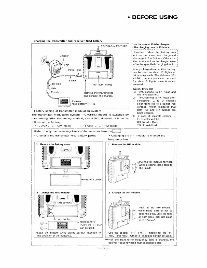
• Charging the transmitter and receiver Nicd battery*Use the special Futaba charger.• The charging time is 15 hours.
[However when the battery wasnot used for some time, charge anddischarge it 2 — 3 times. Otherwise,the battery will not be charged evenafter the specified charging time !
• Factory setting of transmitter modulation system
The transmitter modulation system (PCM/PPM mode) is switched by
data setting. (For the setting method, see P19.). However, it is set as
follows at the factory:
FP-T7UAP . . . . . PCM mode FP-T7UAF . . . . . PPM mode
A fully-charged transmitter batterycan be used for about 10 flights of10 minutes each. The airborne NR-4J Nicd battery pack can be usedfor about 6 flights when 6 servosare used.
Notes: (PBC-8B)1) First, connect to TX Nicad and
red lamp goes on.2) Then, connect to RX Nicad after
connecting, L, E, D, changescolor from red to greenish red(orange) which indicates thatboth TX and RX Nicads arebeing charged.
3) In case of separate charging, L,E, D, color will be:RX Nicad - GreenTX Nicad- Red
ReceiverNicd battery NR-4J
Remove the charging capand connect the charger.
(NT-8LP inside)
Tx sideRx side
Male
Female
Charger
LED
Power plug
FP-7UAPor FP-7UAF
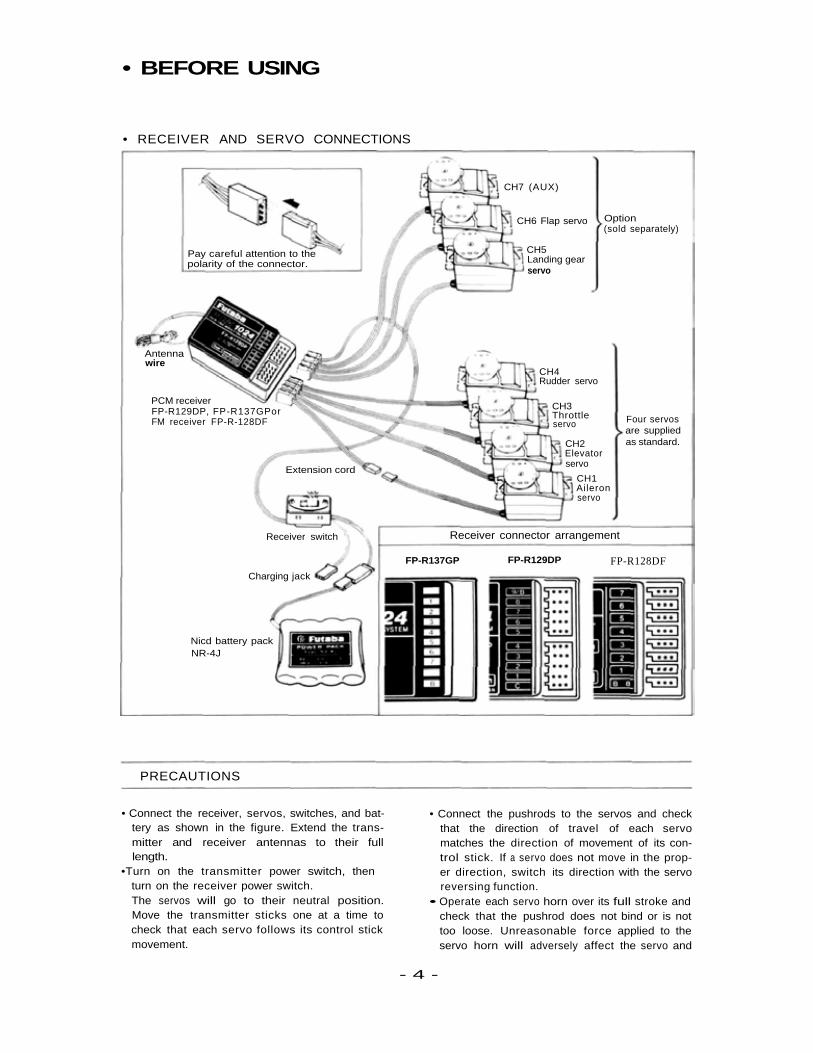
• Changing the transmitter Nicd battery pack • Changing the RF module to change the
frequency band
Remove the battery cover.
— 3 —
Battery cover
1 Remove the RF module.
Pull the RF module forwardwhile pressing these tabs tothe inside
2 Change the Nicd battery. 2 Change the RF module.
® side contact-Nicd battery
(Only the NT-8LPcan be used.)
*Load the battery while paying careful attention tothe direction of the contacts.
Push in the new module,while being careful not tobend the pins, until the tabsat both sides lock into placewith a "click".
*Use the special FP-TP-FM RF module for the FP-7UAP and 7UAF. Other RF modules cannot be used.
•When the transmitter frequency band is changed, thereceiver frequency band must be changed also.
Refer to only the necessary items of the items enclosed in
• BEFORE USING
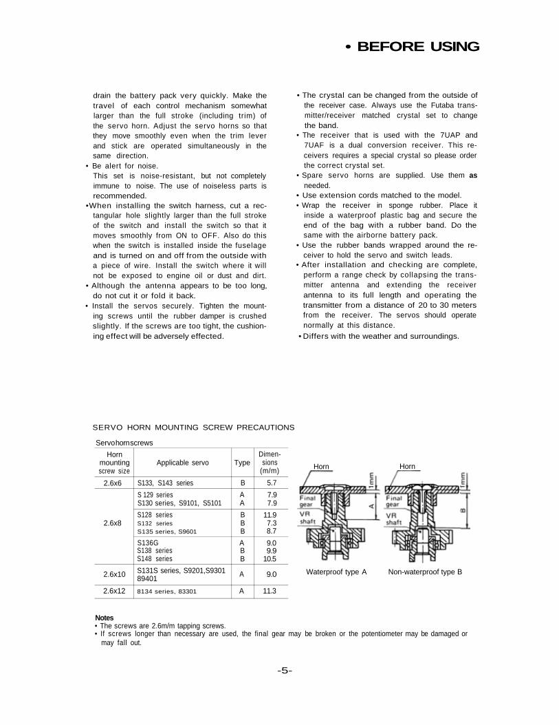
• RECEIVER AND SERVO CONNECTIONS
Pay careful attention to thepolarity of the connector.
CH7 (AUX)
CH6 Flap servo
CH5Landing gearservo
Option(sold separately)
Antennawire
PCM receiverFP-R129DP, FP-R137GPorFM receiver FP-R-128DF
CH4Rudder servo
CH3Throttleservo Four servos
are suppliedas standard.CH2
Elevatorservo
CH1Aileronservo
Extension cord
Receiver switch
Charging jack
Receiver connector arrangement
FP-R137GP FP-R129DP FP-R128DF
Nicd battery packNR-4J
PRECAUTIONS
• Connect the receiver, servos, switches, and bat-tery as shown in the figure. Extend the trans-mitter and receiver antennas to their fulllength.
•Turn on the transmitter power switch, thenturn on the receiver power switch.The servos will go to their neutral position.Move the transmitter sticks one at a time tocheck that each servo follows its control stickmovement.
• Connect the pushrods to the servos and checkthat the direction of travel of each servomatches the direction of movement of its con-trol stick. If a servo does not move in the prop-er direction, switch its direction with the servoreversing function.
• Operate each servo horn over its full stroke andcheck that the pushrod does not bind or is nottoo loose. Unreasonable force applied to theservo horn will adversely affect the servo and
- 4 -
• BEFORE USING
drain the battery pack very quickly. Make thetravel of each control mechanism somewhatlarger than the full stroke (including trim) ofthe servo horn. Adjust the servo horns so thatthey move smoothly even when the trim leverand stick are operated simultaneously in thesame direction.
• Be alert for noise.This set is noise-resistant, but not completelyimmune to noise. The use of noiseless parts isrecommended.
•When installing the switch harness, cut a rec-tangular hole slightly larger than the full strokeof the switch and install the switch so that itmoves smoothly from ON to OFF. Also do thiswhen the switch is installed inside the fuselageand is turned on and off from the outside witha piece of wire. Install the switch where it willnot be exposed to engine oil or dust and dirt.
• Although the antenna appears to be too long,do not cut it or fold it back.
• Install the servos securely. Tighten the mount-ing screws until the rubber damper is crushedslightly. If the screws are too tight, the cushion-ing effect will be adversely effected.
• The crystal can be changed from the outside ofthe receiver case. Always use the Futaba trans-mitter/receiver matched crystal set to changethe band.
• The receiver that is used with the 7UAP and7UAF is a dual conversion receiver. This re-ceivers requires a special crystal so please orderthe correct crystal set.
• Spare servo horns are supplied. Use them asneeded.
• Use extension cords matched to the model.• Wrap the receiver in sponge rubber. Place it
inside a waterproof plastic bag and secure theend of the bag with a rubber band. Do thesame with the airborne battery pack.
• Use the rubber bands wrapped around the re-ceiver to hold the servo and switch leads.
• After installation and checking are complete,perform a range check by collapsing the trans-mitter antenna and extending the receiverantenna to its full length and operating thetransmitter from a distance of 20 to 30 metersfrom the receiver. The servos should operatenormally at this distance.
• Differs with the weather and surroundings.
SERVO HORN MOUNTING SCREW PRECAUTIONS
Servo horn screws
Hornmountingscrew size
2.6x6
2.6x8
2.6x10
2.6x12
Applicable servo
S133, S143 series
S 129 seriesS130 series, S9101, S5101
S128 seriesS132 seriesS135 series, S9601
S136GS138 seriesS148 series
S131S series, S9201,S930189401
8134 series, 83301
Type
B
AA
BBB
ABB
A
A
Dimen-sions
(m/m)
5.7
7.97.9
11.97.38.7
9.09.9
10.5
9.0
11.3
Horn Horn
Waterproof type A Non-waterproof type B
Notes• The screws are 2.6m/m tapping screws.• If screws longer than necessary are used, the final gear may be broken or the potentiometer may be damaged or
may fall out.
-5-
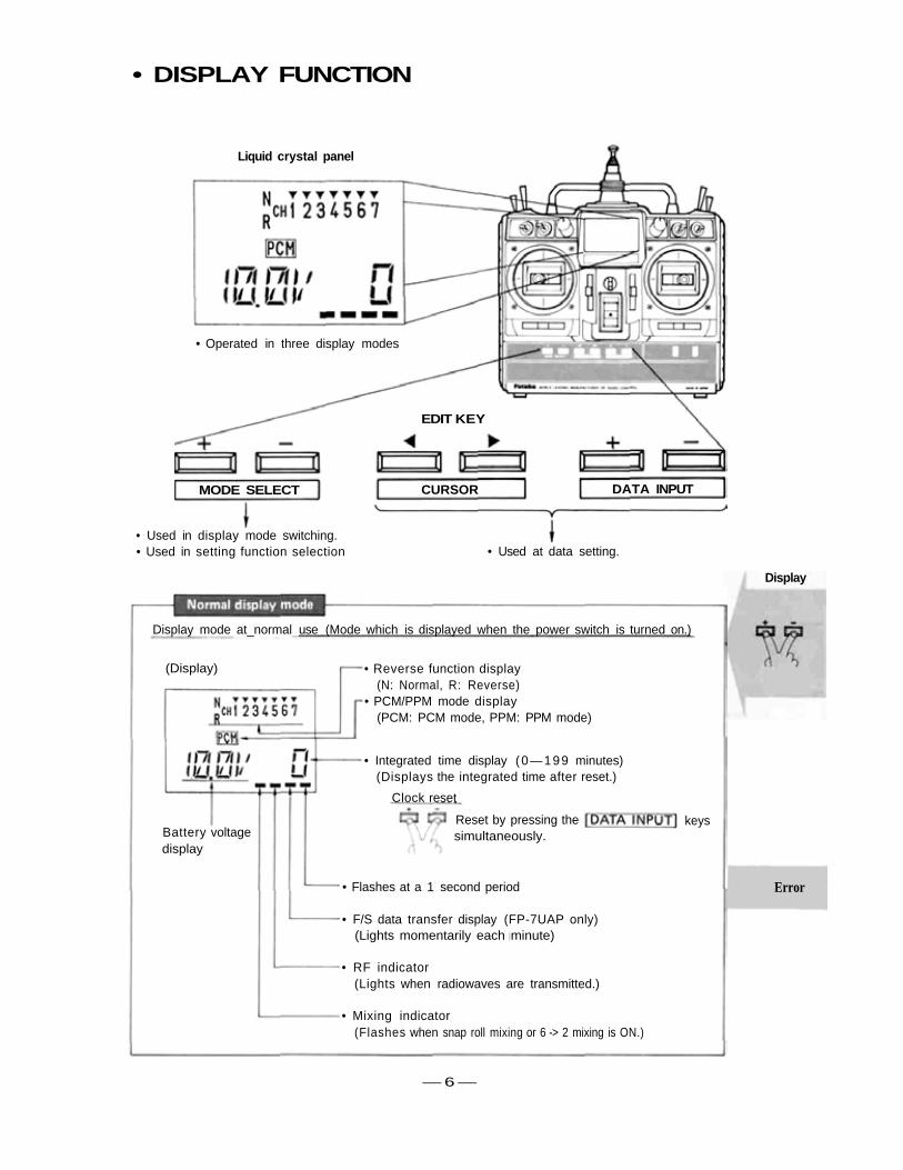
• DISPLAY FUNCTION
• Used in display mode switching.• Used in setting function selection • Used at data setting.
Liquid crystal panel
• Operated in three display modes
CURSOR DATA INPUTMODE SELECT
EDIT KEY
Display
Display mode at_normal use (Mode which is displayed when the power switch is turned on.)
(Display)
Battery voltagedisplay
• Reverse function display(N: Normal, R: Reverse)
• PCM/PPM mode display(PCM: PCM mode, PPM: PPM mode)
• Integrated time display (0—199 minutes)(Displays the integrated time after reset.)
Clock reset
— 6 —
• Flashes at a 1 second period
• F/S data transfer display (FP-7UAP only)(Lights momentarily each minute)
• RF indicator(Lights when radiowaves are transmitted.)
• Mixing indicator(Flashes when snap roll mixing or 6 -> 2 mixing is ON.)
Error
Reset by pressing the keyssimultaneously.
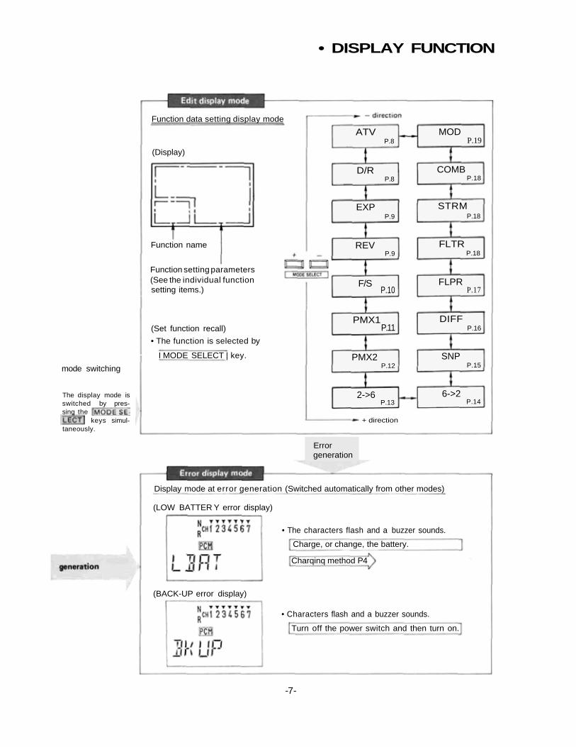
• DISPLAY FUNCTION
mode switching
The display mode isswitched by pres-sinq the
keys simul-taneously.
(Set function recall)
• The function is selected by
I MODE SELECT | key.
Function setting parameters(See the individual functionsetting items.)
Function name
(Display)
Function data setting display mode
ATV MOD
D/R
P.8 P.19
P.8 P.18COMB
EXP STRMP.18P.9
REVP.9
FLTRP.18
F/SP.10
FLPRP.17
PMX1P.11
DIFFP.16
PMX2P.12
SNPP.15
2->6P.13
6->2P.14
+ direction
Errorgeneration
Display mode at error generation (Switched automatically from other modes)
(LOW BATTER Y error display)
• The characters flash and a buzzer sounds.
Charge, or change, the battery.
Charqinq method P4
• Characters flash and a buzzer sounds.
Turn off the power switch and then turn on.
(BACK-UP error display)
-7-
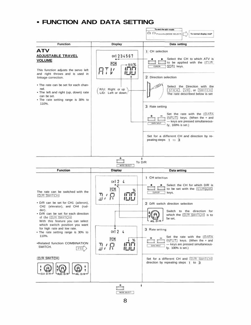
• FUNCTION AND DATA SETTING
Set for a different CH anddirection by repeating steps to
Set the rate with thekeys. (When the + and
— keys are pressed simultaneous-ly. 100% is set.)
•Related function COMBINATIONSWITCH.
• D/R can be set for CH1 (aileron),CH2 (elevator), and CH4 (rud-der).
• D/R can be set for each directionof theWith this feature you can selectwhich switch position you wantfor high rate and low rate.
• The rate setting range is 30% to110%.
The rate can be switched with the
Switch to the direction forwhich the is tobe set.
D/R switch direction selection
Select the CH for which D/R isto be set with thekeys.
To D/R
Set for a different CH and direction by re-peating steps
Set the rate with thekeys. (When the + and
— keys are pressed simultaneous-ly, 100% is set.)
The rate described below is set, or
Select the Direction with theR/U: Right or upL/D: Left or down
• The rate can be set for each chan-nel.
• The left and right (up, down) ratecan be set.
• The rate setting range is 30% to110%.
This function adjusts the servo leftand right throws and is used inlinkage correction.
Select the CH to which ATV isto be applied with the
keys.
CH selection
Direction selection
Rate setting
ATVADJUSTABLE TRAVELVOLUME
Press the [MODE SELECT] To normal display mod*
Function Display Data setting
8
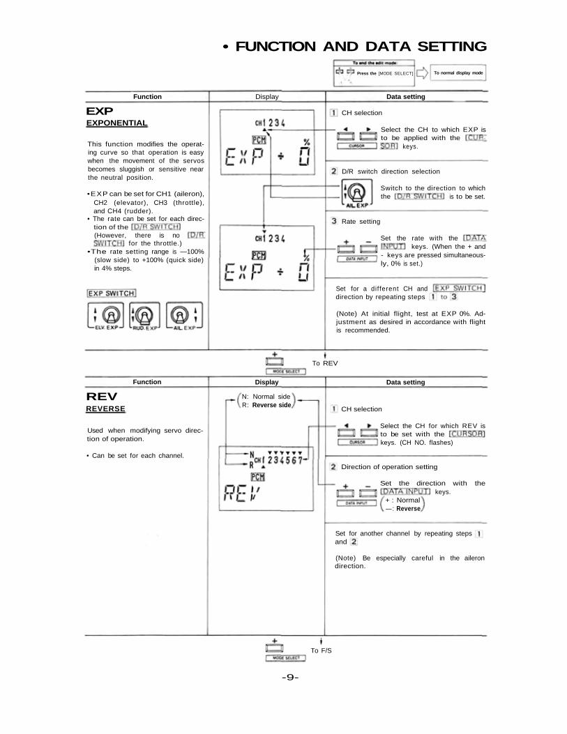
• FUNCTION AND DATA SETTING
To REV
To F/S
Function Display Data setting
CH selection
Select the CH to which EXP isto be applied with the
keys.
EXPEXPONENTIAL
This function modifies the operat-ing curve so that operation is easywhen the movement of the servosbecomes sluggish or sensitive nearthe neutral position.
•EXP can be set for CH1 (aileron),CH2 (elevator), CH3 (throttle),and CH4 (rudder).
• The rate can be set for each direc-tion of the(However, there is no
for the throttle.)•The rate setting range is —100%
(slow side) to +100% (quick side)in 4% steps.
D/R switch direction selection
Switch to the direction to whichthe is to be set.
Rate setting
Set the rate with thekeys. (When the + and
- keys are pressed simultaneous-ly, 0% is set.)
Set for a dif ferent CH anddirection by repeating steps
(Note) At initial flight, test at EXP 0%. Ad-justment as desired in accordance with flightis recommended.
Function Display Data setting
REVREVERSE
Used when modifying servo direc-tion of operation.
• Can be set for each channel.
N: Normal sideR: Reverse side
CH selection
Select the CH for which REV isto be set with thekeys. (CH NO. flashes)
Direction of operation setting
Set the direction with thekeys.
+ : Normal—: Reverse
Set for another channel by repeating stepsand
(Note) Be especially careful in the ailerondirection.
Press the [MODE SELECT] To normal display mode
-9-
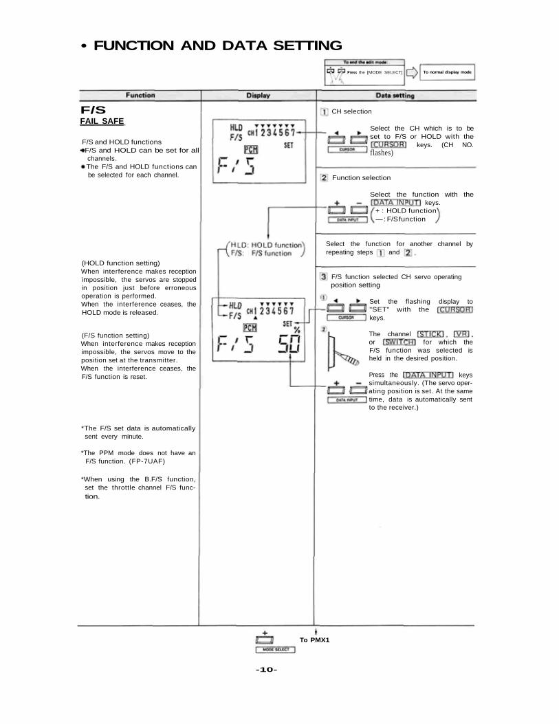
• FUNCTION AND DATA SETTING
Press the [MODE SELECT] To normal display mode
CH selection
Select the CH which is to beset to F/S or HOLD with the
keys. (CH NO.flashes)
Function selection
Select the function with thekeys.
+ : HOLD function— : F/S function
Select the function for another channel byrepeating steps and
F/S function selected CH servo operatingposition setting
Set the flashing display to"SET" with thekeys.
The channelor for which theF/S function was selected isheld in the desired position.
Press the keyssimultaneously. (The servo oper-ating position is set. At the sametime, data is automatically sentto the receiver.)
To PMX1
*The F/S set data is automaticallysent every minute.
*The PPM mode does not have anF/S function. (FP-7UAF)
*When using the B.F/S function,set the throttle channel F/S func-tion.
(F/S function setting)When interference makes receptionimpossible, the servos move to theposition set at the transmitter.When the interference ceases, theF/S function is reset.
(HOLD function setting)When interference makes receptionimpossible, the servos are stoppedin position just before erroneousoperation is performed.When the interference ceases, theHOLD mode is released.
F/S and HOLD functions• F/S and HOLD can be set for all
channels.• The F/S and HOLD functions can
be selected for each channel.
F/SFAIL SAFE
-10-
• FUNCTION AND DATA SETTING
Press the [MODE SELECT] To normal display mode
Mixing activate/inhibit mode setting
Set the mode with thekeys.
+ : Activate—: Inhibit
Master channel selection
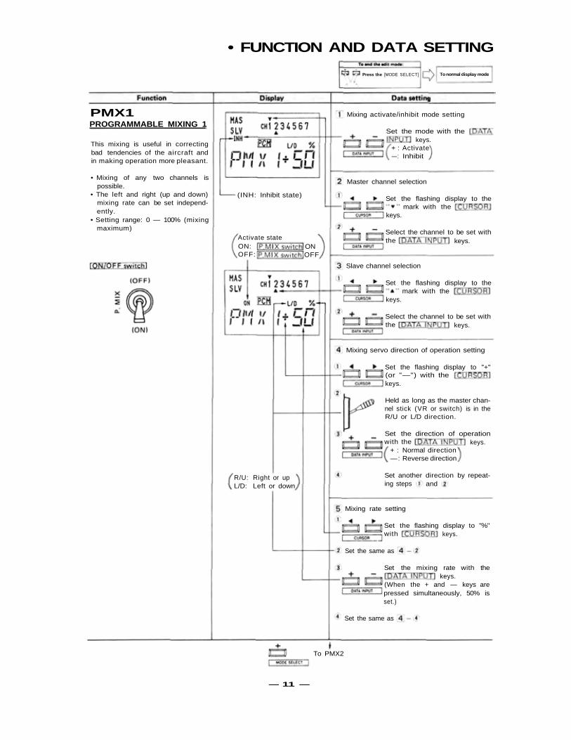
PMX1PROGRAMMABLE MIXING 1
This mixing is useful in correctingbad tendencies of the aircraft andin making operation more pleasant.
• Mixing of any two channels ispossible.
• The left and right (up and down)mixing rate can be set independ-ently.
• Setting range: 0 — 100% (mixingmaximum)
(INH: Inhibit state)
Activate stateON:OFF:
ONOFF
Set the flashing display to themark with the
keys.
Select the channel to be set withthe keys.
Slave channel selection
Set the flashing display to themark with the
keys.
Select the channel to be set withthe keys.
Mixing servo direction of operation setting
Set the flashing display to "+"(or "—") with thekeys.
Held as long as the master chan-nel stick (VR or switch) is in theR/U or L/D direction.
Set the direction of operationwith the keys.
+ : Normal direction—: Reverse direction
Set another direction by repeat-ing steps and
R/U: Right or upL/D: Left or down
Mixing rate setting
Set the flashing display to "%"with keys.
Set the same as
Set the mixing rate with thekeys.
(When the + and — keys arepressed simultaneously, 50% isset.)
Set the same as
To PMX2
— 11 —

• FUNCTION AND DATA SETTING
Press the [MODE SELECT] To normal display mode
Mixing activate/inhibit mode setting
Set the mode with thekeys.
+ : Activate-: Inhibit
Master channel selection
Set the flashing display to themark with the
keys.
Select the channel to be set withkeys.the
Slave channel selection
Set the flashing display to themark with the
keys.
Select the channel to be set withkeys.the
Mixing servo direction of operation setting
Set the flashing display to "+'(or "—") with thekeys.
Held as long as the master chan-nel stick (VR or switch) is in theR/U or L/D direction.
Set the direction of operationwith the keys.
+ : Normal direction- : Reverse direction
Set another direction by repeat-ing steps andR/U: Right or up
L/D: Left or down
Mixing rate setting
Set the flashing display to "%"with keys.
Set the same as
Set the mixing rate with thekeys.
(When the + and — keys arepressed simultaneously, 50% isset.)
Set the same as
To 2-6
PMX2PROGRAMMABLE MIXING 2
This mixing is useful in correctingbad tendencies of the aircraft andin making operation more pleasant.
• Mixing of any two channels ispossible.
• The left and right (up and down)mixing rate can be set independ-ently.
—12—
• FUNCTION AND DATA SETTING
Pressthe [MODE SELECT] To normal display mode
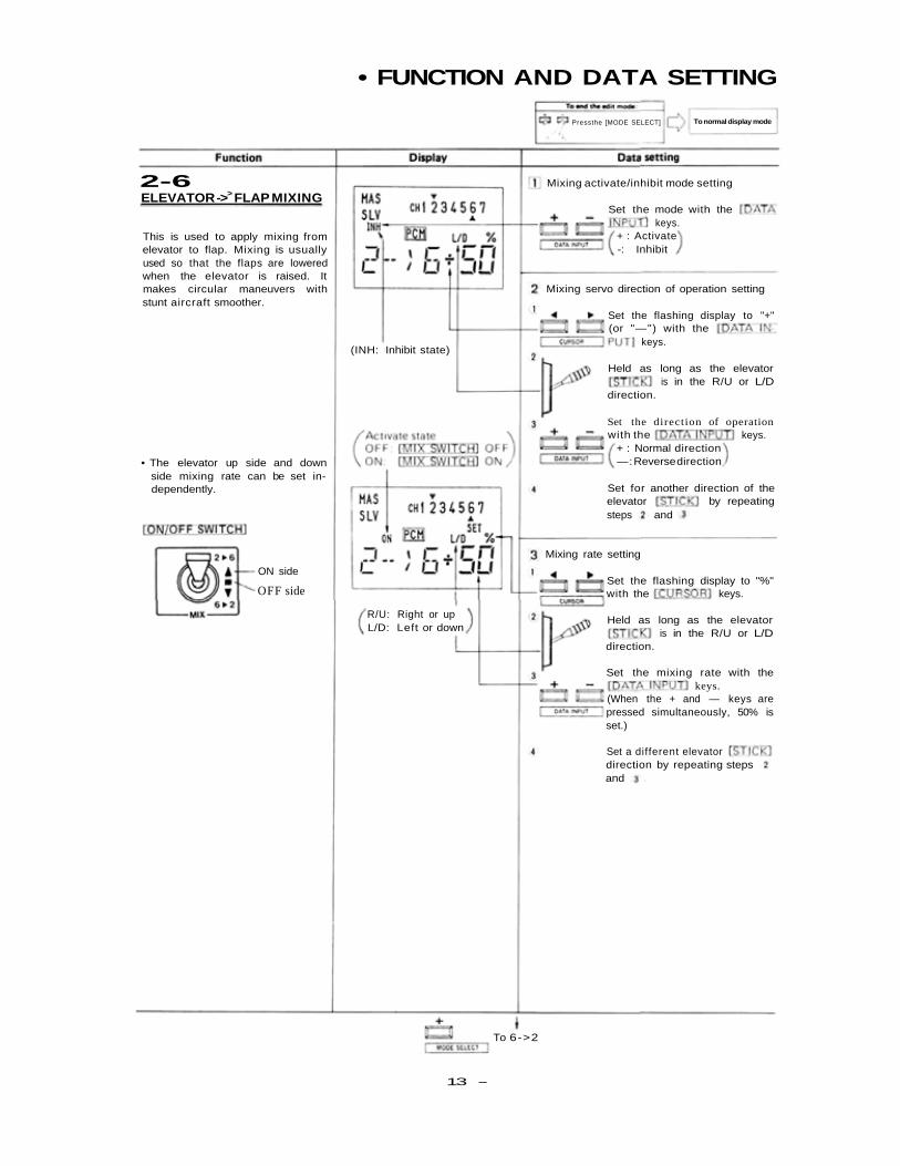
2-6ELEVATOR ->> FLAP MIXING
Mixing activate/inhibit mode setting
Set the mode with thekeys.
+ : Activate-: Inhibit
This is used to apply mixing fromelevator to flap. Mixing is usuallyused so that the flaps are loweredwhen the elevator is raised. Itmakes circular maneuvers withstunt aircraft smoother.
Mixing servo direction of operation setting
Set the flashing display to "+"(or "—") with the
keys.
Held as long as the elevatoris in the R/U or L/D
direction.
Set the direction of operationwith the keys.
+ : Normal direction—: Reverse direction
Set for another direction of theelevator by repeatingsteps and
Mixing rate setting
Set the flashing display to "%"with the keys.
Held as long as the elevatoris in the R/U or L/D
direction.
Set the mixing rate with thekeys.
(When the + and — keys arepressed simultaneously, 50% isset.)
Set a different elevatordirection by repeating stepsand
To 6->2
R/U: Right or upL/D: Left or down
ON side
OFF side
• The elevator up side and downside mixing rate can be set in-dependently.
(INH: Inhibit state)
13 -
• FUNCTION AND DATA SETTING
Press the [MODE SELECT] To normal display mode
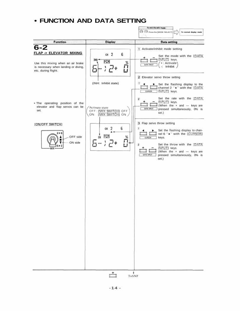
Activate/inhibit mode setting
Set the mode with thekeys.
+ : Activate-: Inhibit
Elevator servo throw setting
Set the flashing display to thechannel 2 with the
keys.
Set the rate with thekeys.
(When the + and — keys arepressed simultaneously, 0% isset.)
Flap servo throw setting
Set the flashing display to chan-nel 6 with thekeys.
Set the throw with thekeys.
(When the + and — keys arepressed simultaneously, 0% isset.)
ToSNP
OFF side
ON side
• The operating position of theelevator and flap servos can beset.
(INH: Inhibit state)
Use this mixing when an air brakeis necessary when landing or diving,etc. during flight.
6-2FLAP -> ELEVATOR MIXING
-14 -
• FUNCTION AND DATA SETTING
Press the [MODE SELECT] To normal display mode
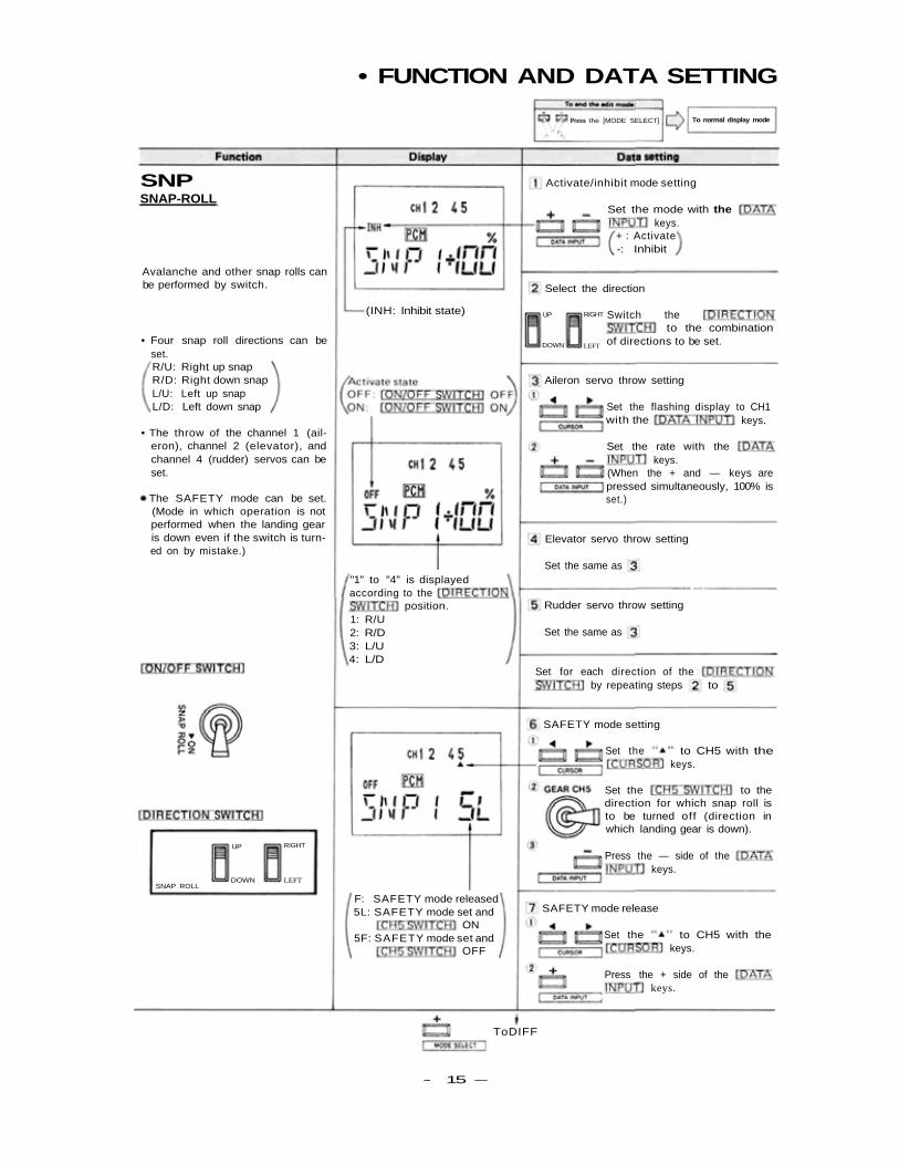
Activate/inhibit mode setting
Set the mode with thekeys.
+ : Activate-: Inhibit
Select the direction
Switch theRIGHTUP
DOWN LEFT
to the combinationof directions to be set.
Aileron servo throw setting
Set the flashing display to CH1with the keys.
Set the rate with thekeys.
(When the + and — keys arepressed simultaneously, 100% isset.)
Elevator servo throw setting
Set the same as
Rudder servo throw setting
Set the same as
Set for each direction of theby repeating steps to
SAFETY mode setting
Set the to CH5 with thekeys.
Set the to thedirection for which snap roll isto be turned off (direction inwhich landing gear is down).
Press the — side of thekeys.
SAFETY mode release
Set the to CH5 with thekeys.
Press the + side of thekeys.
ToDIFF
F: SAFETY mode released5L: SAFETY mode set and
ON5F: SAFETY mode set and
OFF
SNAP ROLL
UP RIGHT
LEFTDOWN
"1" to "4" is displayedaccording to the
position.1: R/U2: R/D3: L/U4: L/D
• The SAFETY mode can be set.(Mode in which operation is notperformed when the landing gearis down even if the switch is turn-ed on by mistake.)
• The throw of the channel 1 (ail-eron), channel 2 (elevator), andchannel 4 (rudder) servos can beset.
• Four snap roll directions can beset.R/U: Right up snapR/D: Right down snapL/U: Left up snapL/D: Left down snap
(INH: Inhibit state)
SNPSNAP-ROLL
Avalanche and other snap rolls canbe performed by switch.
- 15 —
• FUNCTION AND DATA SETTING
Pressthe (MODE SELECT]keys simultaneously
To normal display mode
Activate/inhibit mode setting
Set the mode with thekeys.
+ : Activate-: Inhibit
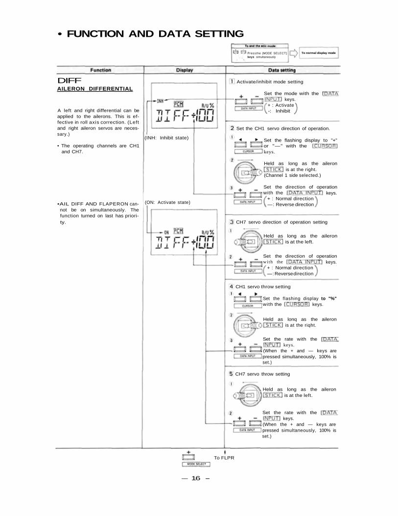
Set the CH1 servo direction of operation.
Set the flashing display to "+"or "—" with thekeys.
Held as long as the aileronis at the right.
(Channel 1 side selected.)
Set the direction of operationwith the keys.
+ : Normal direction—: Reverse direction
CH7 servo direction of operation setting
Held as long as the aileronis at the left.
Set the direction of operationwith the keys.
+ : Normal direction—: Reverse direction
CH1 servo throw setting
Set the flashing display to "%"with the keys.
Held as lonq as the aileronis at the riqht.
Set the rate with thekeys.
(When the + and — keys arepressed simultaneously, 100% isset.)
CH7 servo throw setting
Held as long as the aileronis at the left.
Set the rate with thekeys.
(When the + and — keys arepressed simultaneously, 100% isset.)
To FLPR
•AIL DIFF AND FLAPERON can-not be on simultaneously. Thefunction turned on last has priori-ty.
A left and right differential can beapplied to the ailerons. This is ef-fective in roll axis correction. (Leftand right aileron servos are neces-sary.)
• The operating channels are CH1and CH7.
DIFFAILERON DIFFERENTIAL
(INH: Inhibit state)
(ON: Activate state)
— 16 -
• FUNCTION AND DATA SETTING
Press the [MODE SELECT] To normal display mode
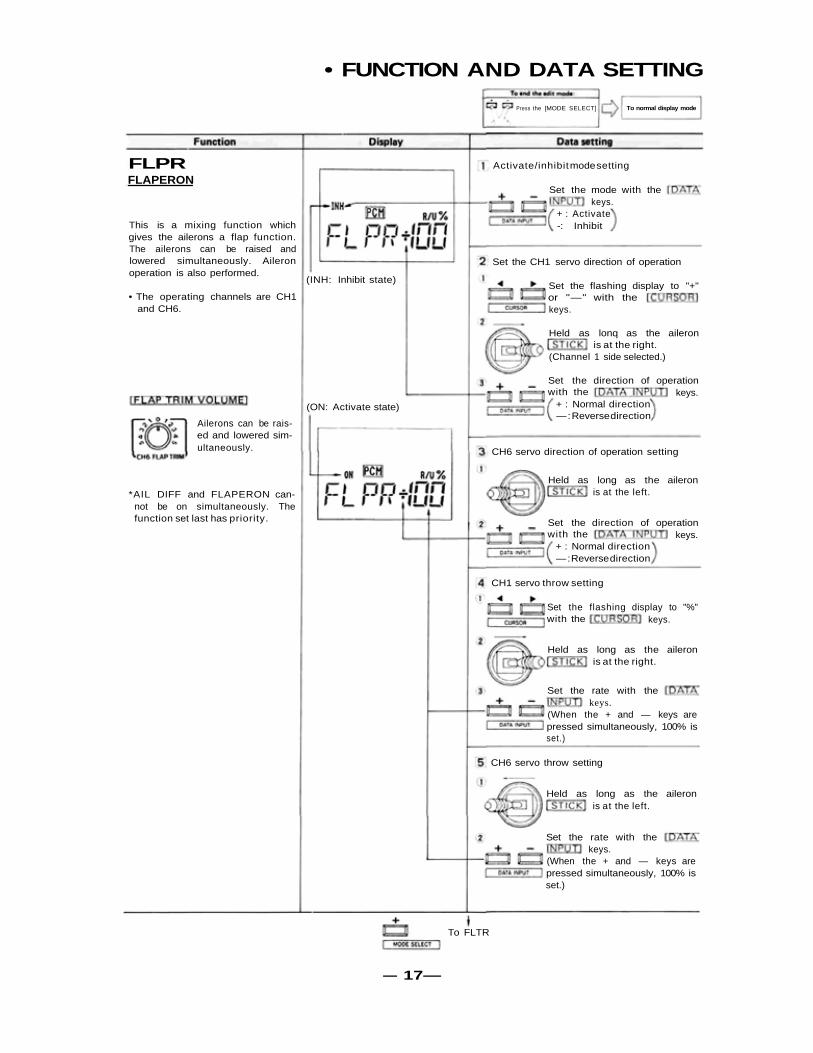
Activate/inhibit mode setting
Set the mode with thekeys.
+ : Activate-: Inhibit
Set the CH1 servo direction of operation
Set the flashing display to "+"or "—" with thekeys.
Held as lonq as the aileronis at the right.
(Channel 1 side selected.)
Set the direction of operationkeys.with the
+ : Normal direction—: Reverse direction
CH6 servo direction of operation setting
Held as long as the aileronis at the left.
Set the direction of operationwith the keys.
+ : Normal direction—: Reverse direction
CH1 servo throw setting
Set the flashing display to "%"with the keys.
Held as long as the aileronis at the right.
Set the rate with thekeys.
(When the + and — keys arepressed simultaneously, 100% isset.)
CH6 servo throw setting
Held as long as the aileronis at the left.
Set the rate with thekeys.
(When the + and — keys arepressed simultaneously, 100% isset.)
To FLTR
(ON: Activate state)
(INH: Inhibit state)
FLPRFLAPERON
This is a mixing function whichgives the ailerons a flap function.The ailerons can be raised andlowered simultaneously. Aileronoperation is also performed.
• The operating channels are CH1and CH6.
Ailerons can be rais-ed and lowered sim-ultaneously.
*AIL DIFF and FLAPERON can-not be on simultaneously. Thefunction set last has priority.
— 17—
• FUNCTION AND DATA SETTING
Press the. [MODE SELECT] To normal display mode
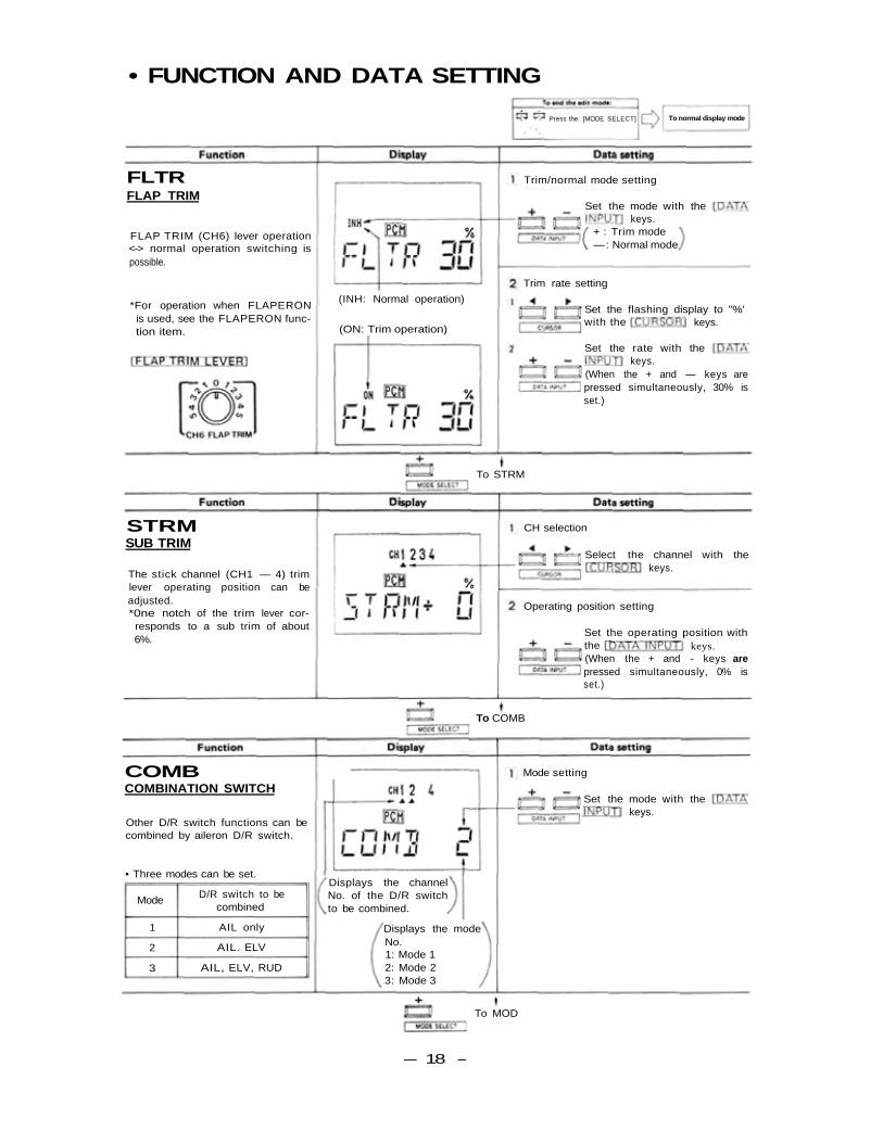
FLTRFLAP TRIM
FLAP TRIM (CH6) lever operation<-> normal operation switching ispossible.
*For operation when FLAPERONis used, see the FLAPERON func-tion item.
STRMSUB TRIM
The stick channel (CH1 — 4) trimlever operating position can beadjusted.*0ne notch of the trim lever cor-
responds to a sub trim of about6%.
COMBCOMBINATION SWITCH
Other D/R switch functions can becombined by aileron D/R switch.
• Three modes can be set.
Mode
1
2
3
D/R switch to becombined
AIL only
AIL. ELV
AIL, ELV, RUD
To MOD
Displays the modeNo.1: Mode 12: Mode 23: Mode 3
Displays the channelNo. of the D/R switchto be combined.
(INH: Normal operation)
(ON: Trim operation)
Trim/normal mode setting
Set the mode with thekeys.
+ : Trim mode—: Normal mode
Trim rate setting
Set the flashing display to "%'keys.with the
Set the rate with thekeys.
(When the + and — keys arepressed simultaneously, 30% isset.)
CH selection
To STRM
Select the channel with thekeys.
Operating position setting
Set the operating position withkeys.the
(When the + and - keys arepressed simultaneously, 0% isset.)
To COMB
Mode setting
Set the mode with thekeys.
— 18 -
• FUNCTION AND DATA SETTING• OTHER FUNCTIONS
Press the [MODE SELECT] To normal display mode
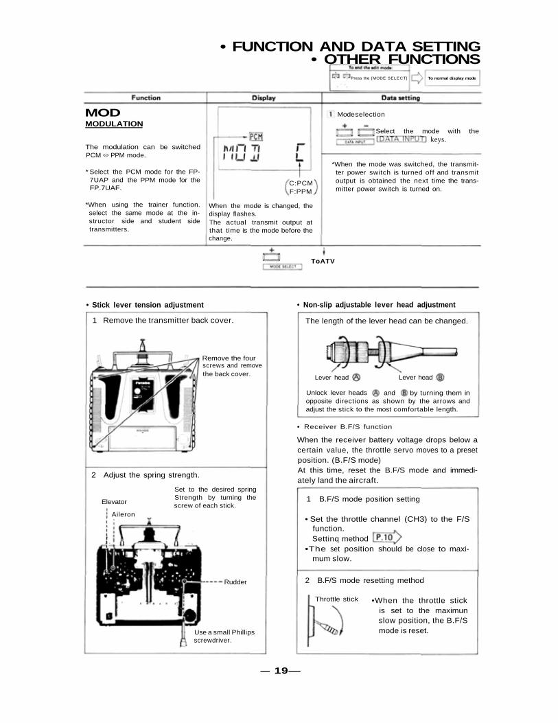
Mode selectionMODMODULATION
The modulation can be switchedPCM <-> PPM mode.
* Select the PCM mode for the FP-7UAP and the PPM mode for theFP.7UAF.
*When using the trainer function.select the same mode at the in-structor side and student sidetransmitters.
When the mode is changed, thedisplay flashes.The actual transmit output atthat time is the mode before thechange.
*When the mode was switched, the transmit-ter power switch is turned off and transmitoutput is obtained the next time the trans-mitter power switch is turned on.
Select the mode with thekeys.
C:PCMF:PPM
ToATV
• Non-slip adjustable lever head adjustment• Stick lever tension adjustment
1 Remove the transmitter back cover.
Remove the fourscrews and removethe back cover.
The length of the lever head can be changed.
Lever head Lever head
Unlock lever heads and by turning them inopposite directions as shown by the arrows andadjust the stick to the most comfortable length.
• Receiver B.F/S function
When the receiver battery voltage drops below acertain value, the throttle servo moves to a presetposition. (B.F/S mode)At this time, reset the B.F/S mode and immedi-ately land the aircraft.
2 Adjust the spring strength.
Set to the desired springStrength by turning thescrew of each stick.Elevator
Aileron
Rudder
Use a small Phillipsscrewdriver.
1 B.F/S mode position setting
• Set the throttle channel (CH3) to the F/Sfunction.Settinq method
•The set position should be close to maxi-mum slow.
2 B.F/S mode resetting method
Throttle stick •When the throttle stickis set to the maximunslow position, the B.F/Smode is reset.
— 19—

• OTHER FUNCTIONS• USING THE ACCESSORIES
• Trainer function (Trainer cable optional)
2 Operating at the instructor side
Operation is possible by turning on theinstructor transmitter power switch. Atthis time, turn off the trainer switch.
1 Connection to transmitter
Trainer switch
Student transmitter
Instructor transmitter
Trainer cable (6-conductor)
3 Operating at the student side
Operation is possible at the studenttransmitter while the trainer switch atthe instructor side is held in the ONstate.*Operation is impossible if the instructor transmitter modulation
mode and student transmitter modulation mode is different. Setto the same mode before using. Setting methodAlways turn off the student transmitter power switch. Do notoperate the trainer switch either.
*Use the functions of the other two transmitters with the samesetting.
• SPLINED HORNSThis horn permits shifting of theservo neutral position at the servohorn. Setting and shifting theneutral position.a) Angle divisions
1) The splined horn has 25 seg-ments. The amount of change persegment is; 360/25=14.4°.2) The minimum adjustable angleis determined by the number ofarms or number of the holes. Forfour arms, the minimum adjust-able angle is:
b) Effect
To shift the holes center line tothe right (clockwise) relative tobaseline A, shift arm 2 to the po-sition of arm 1 and set it to theposition closest to baseline A.[Example] For a four arm horn,the angular shift per segment is14.4°. The shift to the right is 90°- (14.4 x 6) = 3.6°.To shift by the same angle in theopposite direction, use the oppo-site arm number.
For a six arm horn, turn the armcounterclockwise and set arm 2to the position of arm 1. The ad-justable angle is 60° - (14.4 x 4)=2.4°.Arm 3 shift 4.8° to the right, arm6 shifts 2.4° to the left, and arm 4shifts 7.2° to the right and left.
The following splined horns are optional.
— 20—
HORN A(FSH6X)
HORN B(FSH 6)
HORN C(FSH 6A)
HORN D(FSH 6W)
HORN E HORN F HORN G
• USING THE ACCESSORIES
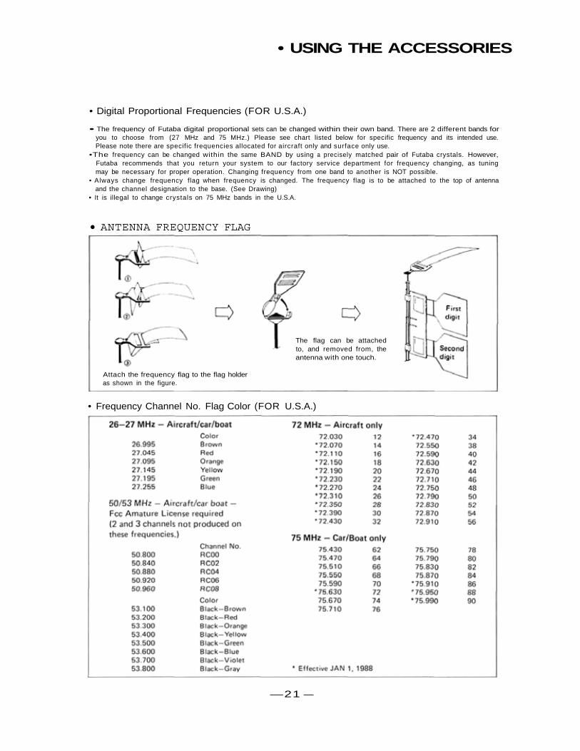
• Digital Proportional Frequencies (FOR U.S.A.)
• The frequency of Futaba digital proportional sets can be changed within their own band. There are 2 different bands foryou to choose from (27 MHz and 75 MHz.) Please see chart listed below for specific frequency and its intended use.Please note there are specific frequencies allocated for aircraft only and surface only use.
•The frequency can be changed within the same BAND by using a precisely matched pair of Futaba crystals. However,Futaba recommends that you return your system to our factory service department for frequency changing, as tuningmay be necessary for proper operation. Changing frequency from one band to another is NOT possible.
• Always change frequency flag when frequency is changed. The frequency flag is to be attached to the top of antennaand the channel designation to the base. (See Drawing)
• It is illegal to change crystals on 75 MHz bands in the U.S.A.
• ANTENNA FREQUENCY FLAG
• Frequency Channel No. Flag Color (FOR U.S.A.)
—21 —
The flag can be attachedto, and removed from, theantenna with one touch.
Attach the frequency flag to the flag holderas shown in the figure.
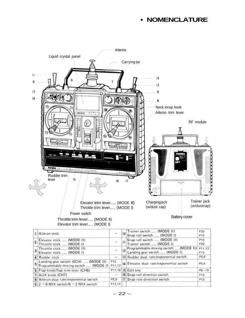
• NOMENCLATURE
Elevator trim lever..... (MODE II)Throttle trim lever..... (MODE I)
Power switch
Throttle trim lever..... (MODE II)Elevator trim lever..... (MODE I)
Battery cover
Trainer jack(w/dustcap)
Charging jack(w/dust cap)
Neck strap hookAileron trim lever
RF module
Carrying bar
Antenna
Liquid crystal panel
Rudder trimlever
— 22 —
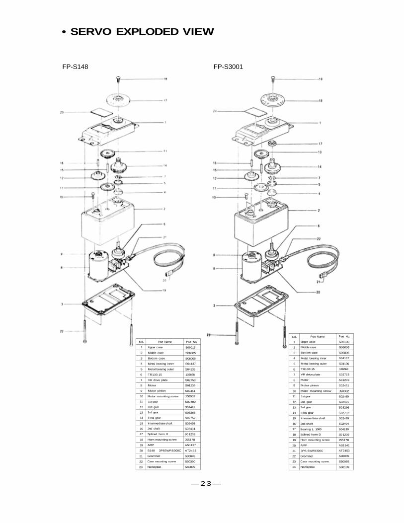
• SERVO EXPLODED VIEW
FP-S148 FP-S3001
No.
1
2
3
4
5
6
7
8
9
10
11
12
13
14
15
16
17
18
19
20
21
22
23
Part Name
Upper case
Middle case
Bottom case
Metal bearing inner
Metal bearing outer
TR133 15
VR drive plate
Motor
Motor pinion
Motor mounting screw
1st gear
2nd gear
3rd gear
Final gear
Intermediate shaft
2nd shaft
Splined horn 0
Horn mounting screw
AMP
S148 3P8SWRB300C
Grommet
Case mounting screw
Nameplale
Part No.
S06015
S06005
S06006
S04137
S04136
139668
S02753
S91239
S02461
J50002
S02490
S02491
S03266
S02752
S02495
S02494
SO 1239
J55178
AS1157
AT2453
S90045
S50360
S60099
No.
1
2
3
4
5
6
7
8
9
10
11
12
13
14
15
16
17
18
19
20
21
22
23
24
Part Name
Upper case
Middle case
Bottom case
Metal bearing inner
Metal bearing outer
TR133 15
VR drive plate
Motor
Motor pinion
Motor mounting screw
1st gear
2nd gear
3rd gear
Final gear
Intermediate shaft
2nd shaft
Bearing L 1060
Splined horn D
Horn mounting screw
AMP
3PB-SWRB300C
Grommet
Case mounting screw
Nameplate
Part No.
S06100
S06005
S06006
S04137
S04136
139668
S02753
S91239
S02461
J50002
S02490
S02491
S03266
S02752
S02495
S02494
S04130
SO 1239
J55178
AS1341
AT2453
S90045
S50085
S60189
— 2 3 —
Printed in Japan/900330CC