SWITCHES, FUSES, & CIRCUIT BREAKERS. OVERVIEW Switches Fuses Circuit Breakers.

All contents copyrighted © 2010 Seven Wanders LLC. All rights reserved
Circuit Protection Fundamentals
What is circuit protection?
Protection is something that people place a high value on. Protection of all forms are visible throughout our daily lives. From the insurance policies that protect vehicles in accidents from severe fi nancial impact to the seat belts and air bags contained in the modern vehicles protecting the occupants from life threatening injuries. Electronic circuits require protection as well. The fundamental way to protect an electronic circuit is to break or stop the fl ow of electrical current. There are many methods by which that result can be achieved. There are also many things about the circuit that must be considered to help infl uence which circuit protection method is most appropriate.
Basic circuit protection addresses three objectives.
1. Proper circuit protection allows enough electrical current to fl ow insuring the proper operation of the equipment when an appropriate value and method of protection are chosen correctly.
2. Proper circuit protection, once engaged or activated, protects the equipment from damage in case of excess current draw.
3. Proper circuit protection, once engaged or activated, protects the battery and other vehicle electrical components from serious damage in case of a defective audio component or wiring to components.
Where is circuit protection installed?
To adequately protect a circuit, the protection device must have control over the circuit. The protection device must be able to MAKE the connection when the circuit is under normal operation, but BREAK the connection when the circuit is in need of protection. This type of connection is called a SERIES connection, or “in line” with the circuit.
Fusing and Circuit BreakersBASIC ELECTRICAL
OBJECTIVES
Discuss the purpose of Fuses and Circuit Breakers in an electrical system Describe the different types of Fuses used in an automotive application Describe the different types of Circuit Breakers used in an automotive application
INTRODUCTION
This lesson explores the fundamental characteristics of electrical circuit protection as well as the devic-es used to protect circuits. Although most people have heard of fuses and circuit breakers, there are many as-pects to consider when choosing the most appropriate type of circuit protection. Simply picking a particular fuse value and inserting it into the circuit may not protect the circuit at all, or it may repeatedly fail and be a source of frustration. With a proper understanding of a variety of circuit protection characteristics, the mobile electron-ics installer is ideally poised to create installations that are safe, functional and that protects the equipment as well as the vehicle and it’s occupants.
1
All contents copyrighted © 2010 Seven Wanders LLC. All rights reserved
2
While it is traditionally the practice of mobile electronic installations to add circuit protection devices on the (+) positive side of the circuit, the protection would be equally as effective if placed on the (-) negative side of the circuit. Since the definition of a circuit is a circular path of electrons flowing, any device that creates a break in that circuit which stops the flow of electrons is, fundamentally, a protection circuit. Where the break happens to occur, whether in the (+) positive or (-) negative portion of the circuit, is virtually of no concern. Methods of circuit protection vary widely and are based on the particular needs of the user and the elec-trical circuit performance. Circuit protection devices are rated by reaction time, current capability, voltage range and environmental use. Some circuit protection devices are able to reset for multiple uses, although the major-ity of circuit protection devices that “trip” and “reset” multiple times have a weaker protection threshold each consecutive cycle. All mobile audio, video, and high current security system components must be protected from short circuits as well as be protected from damaging the vehicle they’re installed in. According to the MECP Basic Installer Study Guide, the purpose for the circuit protection on a wire that connects the amplifier to the (+) battery post is to protect the wire itself (from burning up if shorted) and to protect the vehicle from anything that would be affected by that short circuit or amplifier malfunction. Though this aspect is often overlooked, the primary reason circuit protection is installed is to isolate problems and shut down the operation of that circuit or device, rather than to shut down the entire vehicle elec-trical system. A secondary benefit of protecting each circuit individually is that the protection will likely engage quickly enough to prevent any major component damage to the device(s) connected in the circuit.
Fuses
A fuse is simply a conductive element that heats up and melts (breaks apart) when too much current has passed across the fuse element.
History
The very first fuses were simple open wire devices which were not surrounded by glass, plastic, or any other materials. These were effective for circuit protection, but ambient air temperature created a wide variable in the reliability of the rating of the fuse. With the wire element simply exposed to the ambient air, it was diffi-cult to control the current (electrical heat) that caused the wire to melt and protect the circuit. Good idea, yet too unreliable to be commercially accepted. In the 1890’s, Thomas Edison was creating fuses that were thin wires within a lamp base making the am-bient air effect less significant. As the fuses were built enclosed in a well insulated material, they became more reliable over a wide range of temperatures. By 1904 Underwriters Laboratories (UL) had created some specifications regarding fuse sizes and how they were to be rated to meet the growing demand for reliability of the fuse as a safety device. After all, how safe could a fuse be when no one can ever be sure when it’s going to kick in? By 1914 automotive specific fuses were being used as circuit protection for components of the vehicles electrical system. As early vehicles were typically owned by the wealthy and by important individuals, the pro-tection for the passengers from accidental electrical fires was paramount to the commercial success of the early automobile industry. Shortly after this, two companies began producing fuses for a variety of applications, including for auto-motive uses. The two companies, Bussman and Littlefuse, still manufacture the majority of fuses used in electri-cal systems and electronic products throughout the world.
Fuse Specifications
There are several important specifications that determine the value of a particular fuse. Each area allows a fuse to fit a particular application most efficiently.
All contents copyrighted © 2010 Seven Wanders LLC. All rights reserved
3
Current Rating
This is the nominal amperage value marked on the fuse itself. This rating is intended to have met a particular current threshold during a manufacturers controlled set of test conditions, generally meant to replicate real world scenarios.
Reaction Time
The time a fuse takes to open the circuit path is called the reaction time. Some fuses are “fast acting” while others are “slow blow” types. Depending on the necessity of the fuse to tolerate a brief spike or period of overrated current, a fast or slow reacting fuse would be chosen. Generally in mobile electronic installations, fast acting fuses provide the most protection.
Derivation of nominal melting
This is a testing procedure that verifies both the current rating and a reaction time based on a set of pa-rameters. The actual mathematical process is:
Current Squared x Time = Nominal Melting Current
The process uses a short 8 millisecond pulse (0.008 seconds) as the fixed time to determine the current required to blow the fuse. The current represents the nominal threshold of melting the fuse without affecting the heat on to the other conductive portions of the circuit. The measured current, squared, multiplied by the 8 mil-lisecond pulse (unless the time was LESS than 8ms.) renders the nominal melting current of the fuse element.
Voltage Limit
The voltage limit rating of a fuse indicates the amount of voltage that the circuit can supply while still being safely interrupted if the fuse blows. It is okay to use a fuse with a higher voltage rating than the supply voltage in the circuit, but it is dangerous to do the opposite. Fuses should never be used in an application where the supply voltage exceeds the rated voltage of the fuse. The voltage rating exists because voltage acts as electrical pressure. When there is enough pressure pres-ent, the small gap of a blown fuse element can “arc” and conduct electricity if enough voltage is applied across the fuse. It’s sort of like sparking a metal door handle in a home or office after walking across the carpet. The human body has created a charge of electrical potential difference and, just before the hand meets the handle, the electric spark is conducted. An underrated fuse works the same way. This is the reason why colored plastic automotive fuses are never used in power supplies that are directly plugged into a wall outlet at home.
Fuse Types
AG Fuses
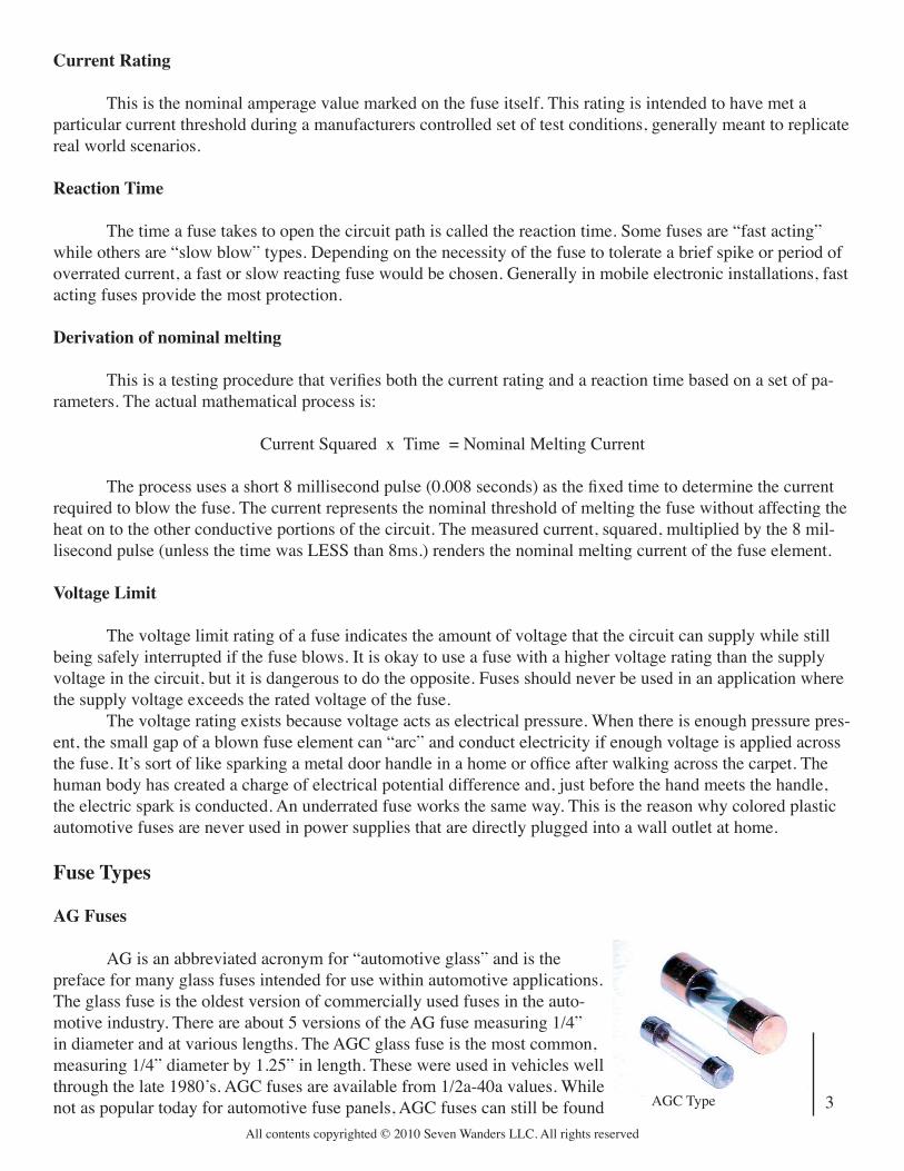
AG is an abbreviated acronym for “automotive glass” and is the preface for many glass fuses intended for use within automotive applications. The glass fuse is the oldest version of commercially used fuses in the auto-motive industry. There are about 5 versions of the AG fuse measuring 1/4” in diameter and at various lengths. The AGC glass fuse is the most common, measuring 1/4” diameter by 1.25” in length. These were used in vehicles well through the late 1980’s. AGC fuses are available from 1/2a-40a values. While not as popular today for automotive fuse panels, AGC fuses can still be found AGC Type
All contents copyrighted © 2010 Seven Wanders LLC. All rights reserved
4
used as internal fuse protection in some mobile audio equipment. AGC styles also have a similar looking “SFE” style cousin with similar dimensional characteristics.
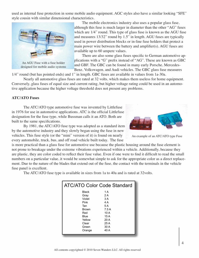
The mobile electronics industry also uses a popular glass fuse, although this fuse is much larger in diameter than the other “AG” fuses which are 1/4” round. This type of glass fuse is known as the AGU fuse and measures 13/32” round by 1.5” in length. AGU fuses are typically used in power distribution blocks or in-line fuse holders that protect a main power wire between the battery and amplifi er(s). AGU fuses are available up to 60 ampere values. There are also some glass fuses specifi c to German automotive ap-plications with a “G” prefi x instead of “AG”. These are known as GBC and GBF. The GBC can be found in many early Porsche, Mercedes-Benz, Volkswagen, and Audi vehicles. The GBC glass fuse measures
1/4” round (but has pointed ends) and 1” in length. GBC fuses are available in values from 1a-30a. Nearly all automotive glass fuses are rated at 32 volts, which makes them useless for home equipment. Conversely, glass fuses of equal size and current rating, but higher voltage rating could be used in an automo-tive application because the higher voltage threshold does not present any problems.
ATC/ATO Fuses
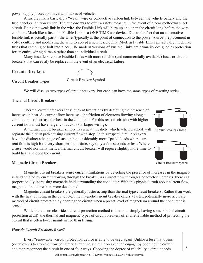
The ATC/ATO type automotive fuse was invented by Littlefuse in 1976 for use in automotive applications. ATC is the offi cial Littlefuse designation for the fuse type, while Bussman calls it an ATO. Both are built to the same specifi cations. By 1981, the ATC/ATO fuse type was adopted as a standard item by the automotive industry and they slowly began using the fuse in new vehicles. This fuse style (or the “mini” version of it) is found on nearly every automobile, truck, bus, and off road vehicle built today. The fuse is more practical than a glass fuse for automotive use because the plastic housing around the fuse element is not prone to breakage under the extreme vibrations experienced within a vehicle. Additionally, because they are plastic, they are color coded to refl ect their fuse value. Even if one were to fi nd it diffi cult to read the small numbers on a particular value, it would be somewhat simple to ask for the appropriate color as a direct replace-ment. Due to the nature of the blades that extend out of the fuse, the contact with the terminals in the vehicle fuse panel is excellent. The ATC/ATO fuse type is available in sizes from 1a to 40a and is rated at 32volts.
An AGU Fuse with a fuse holder designed for mobile audio systems
An example of an ATC/ATO type Fuse
ATC/ATO Color Code StandardBlack 1 AGray 2 AViolet 3 APink 4 ATan 5 ABrown 7.5 ARed 10 ABlue 15 AYellow 20 AClear 25 AGreen 30 AOrange 40 A

All contents copyrighted © 2010 Seven Wanders LLC. All rights reserved
5
Mini (ATM) Fuses
The “Mini Blade” fuse is the offi cial name patented by Littlefuse in 1989 for this miniaturized version of the ATC/ATO style fuse. Mini versions of the ATC/ATO, now known as “Mini” or “ATM” style fuses, were cre-ated to address the continuing need for electrical circuit protection as vehicles continue to have more electrical accessories. With the Mini (ATM) type fuse, an automotive manufacturer can fi t more fuse locations in a given amount of space within a vehicle fuse panel. Virtually all new vehicles now use the Mini (ATM) type fuse. The fuses have silver plating on the blade area to ensure minimal resistance between the fuse and the fuse panel receptacle. Mini (ATM) type fuses are available in sizes from 2a to 30a and are rated at 32volts.
MAXI Fuses
The MAXI version of the ATC/ATO fuse is used primarily for high current circuits in under-the-hood fuse panel applications. The high temperature polymer body of the fuse makes it ideal for environments prone to heat such as the engine compartment. These fuses replace what was once the job of a device known as a fus-ible link. Virtually all new American vehicles now use the MAXI type fuse in an under hood fuse box applica-tion. Like the Mini versions, the MAXI fuses have silver plating on the blade area to ensure minimal resistance between the fuse and the fuse panel receptacle. MAXI type fuses are available in sizes from 20a to 80a and are rated at 32volts.
An example of a Mini (ATM) type Fuse
Mini (ATM) Color Code StandardGray 2 AViolet 3 APink 4 ATan 5 ABrown 7.5 ARed 10 ABlue 15 AYellow 20 AClear 25 AGreen 30 A
An example of a MAXI type Fuse
MAXI Fuse Color Code StandardYellow 20 AClear 25 AGreen 30 AOrange 40 ARed 50 ABlue 60 ANatural 80 A

All contents copyrighted © 2010 Seven Wanders LLC. All rights reserved
6
Mini (ATM)
ATC/ATO
MAXI
Mini (ATM)
ATC/ATO
MAXI
ANL Fuses
ANL Fuses are also known as CNL type fuses and are designed for use in applications as the main power fuse that feeds a distribution block down the line. The ANL fuse is also used to fuse batteries that might be linked together or other applications where high current is present. Due to the wafer style design, the ANL fuse is able to physically bolt down to a dedicated fuse holder. This ensures the
best contact in situa-tions where high current could create unnecessary contact heat that could prematurely melt the fuse (or even the fuse holder). ANL/CNL type fuses are available in sizes from 35a to 500a and are rated at 32volts. Although the fuses are commercially available up to 500a, mobile electronics accessory companies typically offer sizes only as high as 200 to 250a ratings. Any more than 200 to 250 amperes worth of current will exceed the capabilities of the largest available wire to carry the current, and the wire itself then becomes the fuse.
MEGA Fuses
The MEGA fuse is a more refined and heavy duty version of ANL/CNL type fuses. Unlike the ANL/CNL type, the MEGA fuse can be found as OEM equipment on select Ford, Chrysler, and GM
1 2
Here are some examples of newer vehicle fuse panels using Mini (ATM) and MAXI fuse applica-tions. Photo 1 shows the under hood fuse and relay panel in a 2001 Chevrolet Corvette. Photo 2
shows the interior fuse panel (located behind the drivers side dash) in a 2000 model Toyota Corolla
An example of an ANL type Fuse
An ANL Fuse in a fuse holder designed for mobile audio systems

All contents copyrighted © 2010 Seven Wanders LLC. All rights reserved
7
vehicles. Typical applications include main battery fuses or alternator output fuses in OEM electrical systems. MEGA fuses are available in sizes from 100a to 250a (in 25 ampere increments) and are rated at 32volts. Very few aftermarket mobile electronics companies offer a MEGA style fuse holder at this time.
MIDI Fuses
The MIDI fuse was specially created for certain ultra high current applications in BMW and Chrysler vehicles. MIDI fuses are available in 40a, 50a, and 80a sizes and are rated at 32volts. Very few aftermarket mobile electronics companies offer a MIDI style fuse holder at this time.
JCASE (FMX) Fuses
The JCASE fuses were patented by Littlefuse in 1997 and are an alternative fuse for use in under hood applications where the MAXI style fuses have too large a footprint. Also known as the “Female MAXI” or FMX style fuse, the JCASE fuses are commonly found in Japanese vehicles in under hood fuse panels. JCASE (FMX) fuses are available in sizes from 20a to 80a (in 10 ampere increments) and are rated at 32volts. No aftermarket mobile electronics companies offer a JCASE (FMX) style fuse holder at this time. Any JCASE or FMX fuse applications simply involve replacing a fuse in an OEM application.
An example of MEGA (top) and MIDI (bottom) Fuses
Fusible Links
Fuses are generally designed to protect individual circuits, while a Fusible Link is designed to protect an entire electrical circuit or a series of smaller individual circuits that share a common source of power. Fusible Links were more popular for use in older vehicles up to the early 1990’s. As vehicle electrical systems have become more demanding, the Fusible Link has gone by the way of MAXI and JCASE (FMX) style circuit protection as well as MEGA and MIDI style fuses for main
An example of a JCASE (FMX) fuse in a under hood application on a Toyota vehicle
Fusible Link Symbol
All contents copyrighted © 2010 Seven Wanders LLC. All rights reserved
8
power supply protection in certain makes of vehicles. A fusible link is basically a “weak” wire or conductive carbon link between the vehicle battery and the fuse panel or ignition switch. The purpose was to offer a safety measure in the event of a near meltdown short circuit. Being the weak link in the wire, the Fusible Link will burn up and open the circuit long before the wire can burn. Much like a fuse, the Fusible Link is a ONE TIME use device. Due to the fact that an automotive fusible link is actually part of the wire (typically at the point of connection to the power source), replacement in-volves cutting and modifying the wire to accept a new fusible link. Modern Fusible Links are actually much like fuses that can plug or bolt into place. The modern versions of Fusible Links are primarily designed as protection for an entire wiring harness rather than an individual circuit. Many installers replace Fusible Links with more reliable (and commercially available) fuses or circuit breakers that can easily be replaced in the event of an electrical failure.
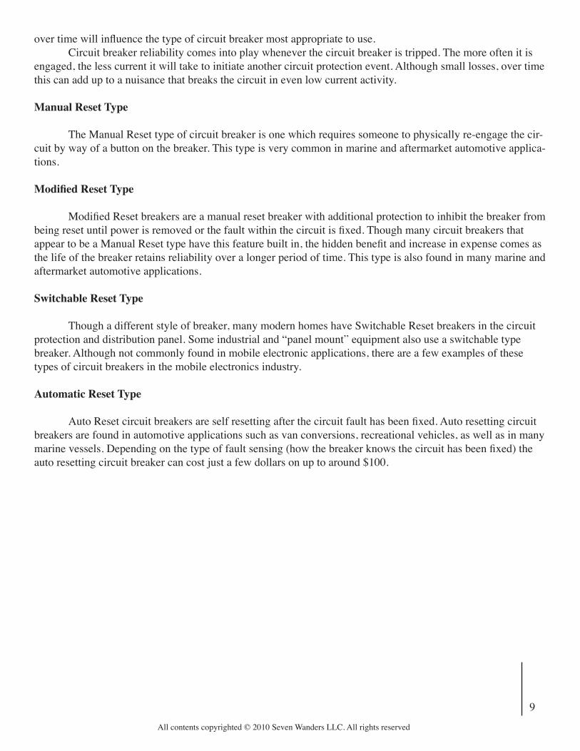
Circuit Breakers
Circuit Breaker Types
We will discuss two types of circuit breakers, but each can have the same types of resetting styles.
Thermal Circuit Breakers
Thermal circuit breakers sense current limitations by detecting the presence of increases in heat. As current flow increases, the friction of electrons flowing along a conductor also increase the heat in the conductor. For this reason, circuits with higher current flow must have larger conductors (or larger wiring). A thermal circuit breaker simply has a heat threshold which, when reached, will separate the circuit path causing current flow to stop. In this respect, circuit breakers have the distinct advantage of sustaining considerably more “peak” loads where cur-rent flow is high for a very short period of time, say only a few seconds or less. Where a fuse would normally melt, a thermal circuit breaker will require slightly more time to build heat and open the circuit.
Magnetic Circuit Breakers
Magnetic circuit breakers sense current limitations by detecting the presence of increases in the magnet-ic field created by current flowing through the breaker. As current flow through a conductor increases, there is a proportionally increasing magnetic field surrounding the conductor. With this physical truth about current flow, magnetic circuit breakers were developed. Magnetic circuit breakers are generally faster acting than thermal type circuit breakers. Rather than work with the heat building in the conductor, the magnetic circuit breaker offers a faster, potentially more accurate method of circuit protection by opening the circuit when a preset level of magnetism around the conductor is sensed. While there is no clear ideal circuit protection method (other than simply having some kind of circuit protection at all), the thermal and magnetic types of circuit breakers offer a renewable method of protecting the circuit that is often lower maintenance than fusing.
How do Circuit Breakers Reset?
Every “renewable” circuit protection device is able to be used again. Unlike a fuse that opens (or “blows”) to stop the flow of electrical current, a circuit breaker can engage by opening the circuit and then reconnect the circuit in one of four ways. Choosing the degree of reliability a circuit needs
Circuit Breaker Symbol
Circuit Breaker Closed
Circuit Breaker Opened
All contents copyrighted © 2010 Seven Wanders LLC. All rights reserved
9
over time will influence the type of circuit breaker most appropriate to use. Circuit breaker reliability comes into play whenever the circuit breaker is tripped. The more often it is engaged, the less current it will take to initiate another circuit protection event. Although small losses, over time this can add up to a nuisance that breaks the circuit in even low current activity.
Manual Reset Type The Manual Reset type of circuit breaker is one which requires someone to physically re-engage the cir-cuit by way of a button on the breaker. This type is very common in marine and aftermarket automotive applica-tions.
Modified Reset Type
Modified Reset breakers are a manual reset breaker with additional protection to inhibit the breaker from being reset until power is removed or the fault within the circuit is fixed. Though many circuit breakers that appear to be a Manual Reset type have this feature built in, the hidden benefit and increase in expense comes as the life of the breaker retains reliability over a longer period of time. This type is also found in many marine and aftermarket automotive applications.
Switchable Reset Type
Though a different style of breaker, many modern homes have Switchable Reset breakers in the circuit protection and distribution panel. Some industrial and “panel mount” equipment also use a switchable type breaker. Although not commonly found in mobile electronic applications, there are a few examples of these types of circuit breakers in the mobile electronics industry.
Automatic Reset Type
Auto Reset circuit breakers are self resetting after the circuit fault has been fixed. Auto resetting circuit breakers are found in automotive applications such as van conversions, recreational vehicles, as well as in many marine vessels. Depending on the type of fault sensing (how the breaker knows the circuit has been fixed) the auto resetting circuit breaker can cost just a few dollars on up to around $100.