Fundamentals of Refining and Petrochemicals Processes
322
NNPC MODIFIED FOUNDATION SKILLS TRAINING PROGRAM LECTURE NOTES ON 1
-
Upload
neocentricgenius -
Category
Documents
-
view
250 -
download
18
description
Notes for Refining Course
Transcript of Fundamentals of Refining and Petrochemicals Processes

NNPC MODIFIED FOUNDATION SKILLS TRAINING
PROGRAM
LECTURE NOTES
ON
FUNDAMENTALS OF REFINING AND PETROCHEMICALS PROCESSES
1

GENERAL OVERVIEW OF REFINING AND PETROCHEMICALS COMPLEX
2

CONTENT
INTRODUCTION
REFINING PROCESSES - FUELS
COMMON PROCESS UNITS IN THE REFINERY
SITING OF REFINING PLANTS
SAFETY AND ENVIRONMENTAL CONCERNS
EVOLUTION OF REFINING PROCESSES
DEVELOPMENT OF REFINING IN NIGERIA
REFINING OPERATIONS :
TYPES OF REFINING PROCESSES ( 4 STEPS ) :
3

INTRODUCTION
Crude oil processing is mainly aimed towards the production of fuels and so only a small fraction of its products is used for specialty chemicals and petrochemicals production. Consequently refineries are set up primarily to produce transportation fuels; Aviation fuels, Gasoline(Petrol) and Automotive Gas oil (Diesel Oil). It is the need to produce more and more of these products from the a barrel of crude oil that has been the force driving refining process design and catalyst technology. Production of speciality products ( solvents, lubricants, petrochemical feedstocks, etc. ) is ancillary to transportation fuels production.
Indeed ⅔ modern conversion refinery output is unleaded gasoline (PMS) and the balance of ⅓ is distributed between LPG, Jet fuels, Diesel fuel, coke, Solvent Extraction for lubricants manufacture and Petrochemicals units to recover Propene, Butenes, Benzene, Toluene and Xylenes for further processing into Polymers.
4

REFINING PROCESSES - FUELS
Crude oil is a very complex mixture of materials, several thousands of them; a lot of some, a little of the others, but thousand of kinds in any case. Crude oils chemical constituents vary with location, age and the depth of the individual well.
As a mixture, Crude Oil is off little practical use but we are able to obtain more than 3000 useful and saleable products from it.
Petroleum Refininig Plants are large sprawling industrial complexes typically with extensive network of pipings carrying streams of fluids between large chemical processing units where Crude Oil is processed into useful petroleum products (LPG, Gasoline / Petrol, Kerosene, Diesel Oil, Heating Oils, Lubricants and Byproducts). In other words, a refinery comprises group of manufacturing plants (units) which vary in number with the variety of products produced.
Refinery Byproducts are processed to products such as Solvents, Detergents, Plastics, Elastomers (Synthetic Rubbers) and Fibres (Nylon and Polyesters).
Refining processes have evolved continuously since the advent of crude distillation in response to changing consumer demand for various premium products and environment protection.
There are three types of Refinery :
5

1. Topping Refinery – a simple refinery made up of CDU, Gas plant and Light hydrocarbon recovery and the necessary Utility system. It produces large amounts of unfinished oils, Residuals.
2. Hydro-skimming Refinery – Topping Refinery into which Hydro-treating and Catalytic Reforming Units have been incorporated. Usually about half of its output is residual fuel oil ( Old PHC Refinery). Operations can be seriously jeopardized in an era of low sulfur fuel oil demand.
3. Conversion Refinery – Hydro-skimming Refinery plus Cat Cracking, Hydro-cracking, Coking, etc., to sharply reduce or eliminate residual fuels
6

COMMON PROCESS UNITS IN THE REFINERY
The number and nature of process units determine Complexity Index of a Refinery. But the Refinery Configuration is the number of the types of processes employed to produce the desired product slate.
The following items are what one may expect to find in a modern day refinery :
The Desalter reduces salts and other contaminants from Crude Oil before distillation.
Atmospheric Distillation for Crude Oil processing into the different cuts and Vacuum Distillation for Residues.
Naphtha Hydrotreater which substantially reduces S, N and metallic impurities from Intermediate stocks.
Catalytic Reforming produces high octane Reformate.
Distillate Hydrotreater desulphurises, denitrogenates and demetallises Middle and Heavy distillates.
Fluid Catalytic Cracker upgrades heavy fractions into lighter and more valuble products.
Hydrocracker is catalytic cracking of heavy fractions but with hydrogenation superimposed.
Visbreaker upgrades heavy residual Oils by thermal cracking into lighter, more valuable products with reduced viscosity.
Coker (Delayed, Fluid- and Flexi-) unit processes very heavy residual Oils into Gasoline, Diesel Oil and Petroleum Coke.
7

Merox unit removes bad odour from LPG, Kerosene and Jet Fuels.
Alkylation unit produces high octane Gasoline blend components.
Dimerisation unit converts Olefins to high octane Gasoline blend components : Butene to Isooctene then Isooctane.
Isomerisation unit converts linear molecules to high octane branched molecules for Gasoline blend.
Steam Reforming for Hydrogen production and Light Olefins.
Amine Gas Treater removes acid gases, e.g. Hydrogen Sulphide from gas streams.
Claus unit converts Hydrogen Sulphide in Tail Gases to Sulphur.
LPG storage Spheres or Bullets.
Storage tanks for Crude Oil, Intermediate and Finished products, usually cylindrical with vapour emission control surrounded by Bound Wall to contain spills.
Utility units such as :
Cooling Towers for circulating cooling water.
Boilers for steam generation.
Compressed Air unit for instrument air and Nitrogen production.
8

Power generation unit and Electrical Sub-Stations.
Waste water collection and treatment facilities to make foul water suitable for reuse or disposal.
Solvent Refining unit to remove unwanted asphaltenic materials and polynuclear aromatics from lube base stocks.
Solvent Dewaxing to remove heavy waxy components from High Vacuum distillates for pour point control.
Solvent Deoiling of Slack waxes to produce Hard Waxes.
9

SITING OF REFINERY AND PETROCHEMICALS PLANT.
The principles are similar to those for other chemical plants:
Reasonable distance from residential areas.
Easy access to raw materials.
Easy access of products delivery to market.
Adequate avalibity of processing energy requirements.
No difficuties in waste (liquid and solids ) disposal.
For plants which use large amounts of process steam and cooling water, an abundant source of water is important. Hence location near navigable rivers or on a sea shore associated to a port.
This also makes cheap transport by river or sea available although transport by pipeline is most economical.
Choice of Areas where abundant space is available so the same company or others can construct Petrochemicals Plants, Solvent manufacturing or similar Plants which will then have easy access to large output of Refinery products and Byproducts.
10

SAFETY / ENVIRONMENTAL CONCERNS
Petroleum Refinery and Petrochemicals Plants release numerous different chemicals into the atmosphere ( fugitive emissions ) : there is substantial air pollution and notable odour accompany their presence.
Other concerns are :
Waste water concerns.
Solid and Sludge disposal
Noise health hazards due to industrial noises.
Risk of accidents such as fire and explosion.
Therefore many government agencies place restrictions on these contaminants, pollution and risks.
Hence most Plants have installed equipment needed to comply with the requirements of the pertinent Environmental Protection Regulatory Agency.
Compliance with these requirements makes it difficult to construct new Plants in some countries (Marathon’s Garyville Louissiana since 1976).
11

EVOLUTION OF REFINING PROCESSES (FIRST COMMERCIAL OIL WELL, 1859)
YEAR PROCESS NAME PURPOSE BY-PRODUCT
1862
1870
1913
1916
1930
1932
1932
1933
1935
1935
Atmospheric Distillation
Vacuum Distillation
Thermal Cracking
Sweetening
Thermal Reforming
Hydrogenation
Coking
Solvent extraction
Solvent Dewaxing
Cat. Oligomerization
Produced kerosene initially
Lubricants (originally) Cracker feedstocks (1930's)
Increased gasoline production
Reduces sulfur& odor
Improves octane number
Remove sulfur and Nitrogen
Produces more gasoline
Lubricant Base oils, Improves viscosity index
Improves pour point
Improve gasoline yield& octane number
Naphtha, tar, etc
Asphalt, residual Coker feed stocks
Bunker fuel
Sulfur
Residual
Sulfur
Coke
Aromatics
Waxes
Petrochemical feedstocks
YEAR PROCESS NAME PURPOSE BY-PRODUCT,
1937
1939
1940
1940
1942
1950
1952
1954
1956
1957
1960
1974
1975
Catalytic Cracking
Visbreaking
Alkylation
Isomerization
Fluid Catalytic Hydrocracker
Deasphalting
Catalytic Reforming
Hydrodesulfurization
Inhibitor sweetening
Catalytic Isomerization
Hydrocracking
Catalytic dewaxing
Residual Hydrocracking
Higher octane gasoline product
Reduces viscosity
Increases gasoline octane & yield
Produces alkylation feedstock
Increases gasoline yield/octane
Upgrades heavy fractions
Increases cracker feedstock
Treats low-quality naphtha
Removes sulfur & Nitrogen
Removes mercaptans
Converts to high octane number
Improves quality/ reduces sulfur
Improves pour point
Increases gasoline yield from residual Oils
Petrochem. feed stocks
Increased distillate, tar
High-octane aviation gasoline
Naphtha
Petrochem. feed stocks
Asphalt
Aromatics
Sulfur
Disulfides
Alkylation feedstocks
Alkylation feedstocks
Wax
Distillates
12

DEVELOPMENT OF PETROLEUM REFINING IN NIGERIA
OLD PORT HARCOURT REFINERY
Commissioned In 1965, Initial Capacity = 35,000 BPSD.
Debottle-necked In 1972 To 60,000 BPSD.
Built To Produce Fuels (PMS Kero, AGO). Hitherto Imported From Europe.
WARRI REFINERY
Commissioned In 1978, Initial Capacity: - 100,000 BPSD.
Debottle Necked In 1986 To A Capacity Of 125,000 BPSD.
KADUNA REFINERY
Commissioned In 1980, Initial Capacity: - 100,000 BPSD.
Debottle Necked In 1986 To A Capacity Of 110,000 BPSD.
NEW PORT HARCOURT REFINERY
COMMISSIONED IN 1989, CAPACITY: - 150,000 BPSD.
13

TYPES OF REFINING PROCESSES
Refining processes can be conveniently grouped into 3 major types:
Separation Processes involving Physical Changes that separate crude into the various fractions depending on the nature of the crude
Conversion Processes involving Chemical Changes / Reactions resulting in the production of marketable materials from crude by skeletal alteration or even alteration fo the chemical type of crude components and may involve Decrease / Increase in Average Molecular Weights or neither.
Catalytic Reforming, Catalytic Cracking, Hydrocracking, Hydrodealkylation, Alkylation, Isomerisation and Polymerisation all involve reactions initiated by acid-type catalyst that promotes carbenium in formation. The other processes are heterogeneous Hydrogenation.
Finishing Processes : Quality Improvement : removal of contaminants and blending various stocks, adding appropriate additives and provide short term storage before products are sold out.
14

REFINING PROCESS - FUELS SCHEMES
REFINING PROCESS SCHEMES
DIFFERENT TYPES AND COMPONENTS
Pages 11 to 13 list different types of Process Units that may be seen in a Refinery and the last page of this note shows KRPC Fuels Plant Flow Scheme.
Components will invariably include Columns, Drums, Coolers, Heat exchangers, Fired heaters, Reactors, Fans, Turbines, Electric Motors, Pumps, Compressors and Net works of pipe line and Instrumentation items.
FACTORS INFLUENCING CHOICE OF SCHEME:
All crude oils are assayed and valued depending on their processibility and potential yields. Crude oils with low assay numbers, called “Opportunity Crudes”, are difficult to process due to higher levels of contaminants and water and are cheap.
15

RAW MATERIAL (FEED STOCK)
CRUDE OILS
16

RAW MATERIAL (FEED STOCKS) – CRUDE OILS
INTRODUCTION: WHAT IS CRUDE OIL
Crude Oil or Petroleum (GK: Petra – Rock; Oleum – Oil or Rock Oil) because found only under Sedimentary Rocks .
Usually greenish brown or blackish gelatinous and free flowing liquid with Boiling Point range: 37.8oC to 760oC (100oF to 1,400oF) and easily transported through pipe lines, barges and ocean liners.
The term crude oil is the name applied to the degassed raw petroleum that has been removed from the ground. Petroleum on the other hand, is the general name applied to an oily, usually dark-colored liquid that occur naturally in many parts of the world. Physically, petroleum is a liquid containing gaseous, liquid, and solid element and its consistency can vary from a liquid as thin as kerosene to a liquid so thick that it can barely flow. Petroleum is believed to be the product of decomposition of certain types of plants or animals. Over a period of hundreds of years these decomposed of organic substances were buried by the decomposed of sand or other inorganic substances and chemical altered by the action of heat and pressure deep within the earth to form petroleum. Petroleum is usually associated with salt water and with natural gas, forming three layers, with the gas above and the salt water below the petroleum. When a well is sunk into the petroleum layer, the petroleum is forced to the surface by the pressure of the natural gas.
17

From the wellhead, the petroleum is run to a high-pressure vessel for flashing off the dissolved natural gas before being run to crude oil storage tanks.
At one time, petroleum was only burned for its fuel content but today it is refined to manufacture fuels such as gasoline, diesel oil, and coke plus specialty products such as benzene and styrene.
Another definition for petroleum is a non-homogeneous mixture of substances of which the main constituents are hydrocarbons along with various quantities of sulfur, oxygen and nitrogen derivatives of hydrocarbons.
Petroleum may also contain dissolved gases in varying amounts and small amounts of metallic compounds.
Petroleum differs widely among themselves in their physical properties.
This is the ratios of hydrocarbon types present. Non-dissolved water is commonly associated with petroleum.
The ratios of the different types of hydrocarbons in a specific crude oil are important in determining the refining process to be used.
ORIGIN OF CRUDE OIL
Crude oils are confirmed to have been formed from Marine Organisms (both Plants and Animals) that lived and died Millions of Years ago. And evidence of its Biological origin stems from presence in it, some of these chemical constituents :
18

Isoprenoids : Natural rubber monomer.
Steriods : Hormones.
Porphyrins : Usually associated with the metallic ( V, Ni or Fe ) contaminants ; Haemoglobin and Chlorophyll.
Many of its compounds have even number of carbon atoms (De-carboxylation).
An American, Edwin L. Drake discovered the first commercial Crude Oil well on–shore in Pennsylvania 1859. Wells are now drilled both on- and off-shore.
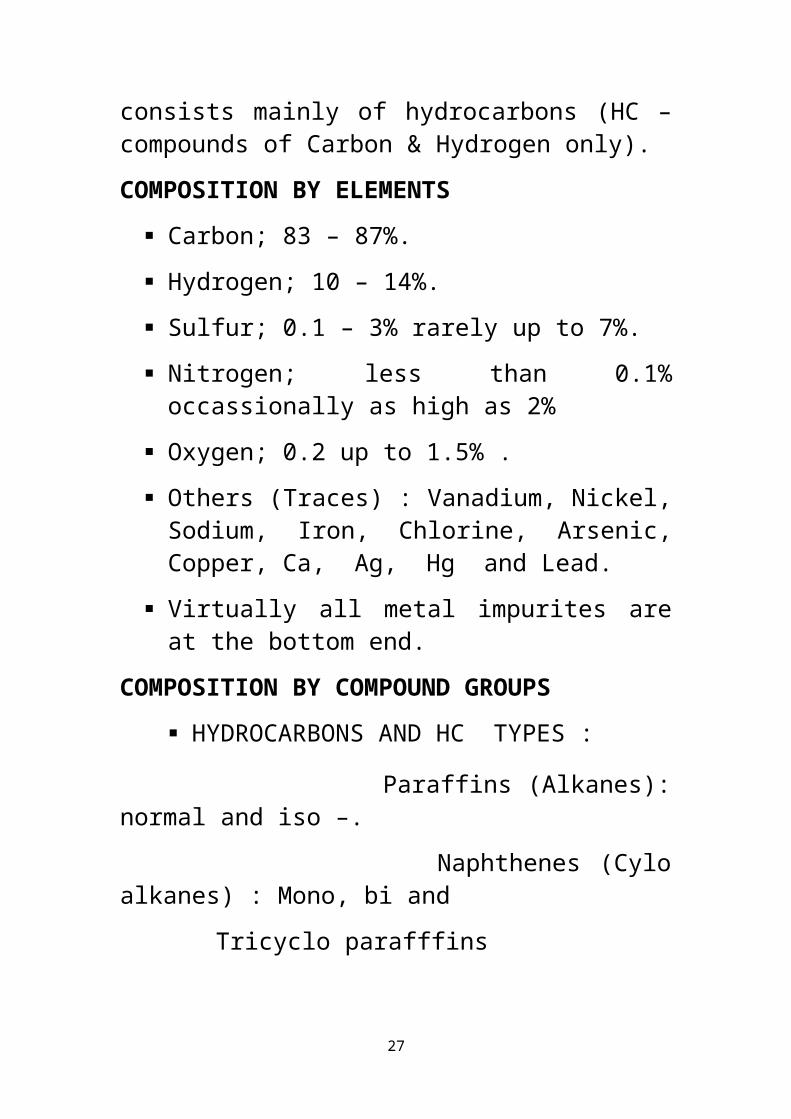
COMPOSITION OF CRUDE OIL
Crude oil is a complex mixture with highly individual composition not exactly matched by any other crude and consists mainly of hydrocarbons (HC – compounds of Carbon & Hydrogen only).
COMPOSITION BY ELEMENTS
Carbon; 83 – 87%.
Hydrogen; 10 – 14%.
Sulfur; 0.1 – 3% rarely up to 7%.
Nitrogen; less than 0.1% occassionally as high as 2%
Oxygen; 0.2 up to 1.5% .
Others (Traces) : Vanadium, Nickel, Sodium, Iron, Chlorine, Arsenic, Copper, Ca, Ag, Hg and Lead.
19

Virtually all metal impurites are at the bottom end.
COMPOSITION BY COMPOUND GROUPS
HYDROCARBONS AND HC TYPES :
Paraffins (Alkanes): normal and iso –.
Naphthenes (Cylo alkanes) : Mono, bi and
Tricyclo parafffins
Aromatics : Benzene, Naphthalene, Anthracene, Phenanthrene, Fluorene, Pyrene, etc.
Hybrid Molecules with alkyl groups attached to Naphthene or Aromatic ring or Naphthenoaromatics.
NON – HC COMPONENTS
Sulfur ( organic and inorganic ) compounds: H2S, Alkylmercaptans, Linear and cyclic sulfides and Disulfides; Thiols, Thiophenol, Thiophene and Diphenyl Disulfide.
Nitrogen compounds: include Pyrrole, Indole, Pyridine, Hydroxipyridine, Quinolines, Hydroxiquinoline, Carbazole, Acridine and Phenanthridine.
Oxygen compounds: Phenols, Aryl Fatty Acids, Naphthenic Acids etc are responsible for crude oil acidity.
Metal ( V, Ni, Fe, etc ) precursors.
20

NB: Olefinic and Acetylenic compounds are not usually present in the crude oil but are products of its processing.
CRUDE OIL ANALYSIS
The tests that are applied to crude and its fractions for effective utilisation and potential market value are:
Physical Properties Measurements (SG, Viscosity etc).
ASTM Distillation for TBP curves.
Chemical Analysis for Sulfur, Nitrogen, Chlorides and Trace metals.
Compounds Data :
Individual Saturates up C8.
Paraffins up to C30 and above.
Naphthenes.
Aromatics.
Hybrid Molecules : Alkyl naphthenes and Alkyl aromatics.
Semi-empirical tests – Pour Point, Cloud point, Octane Rating etc.
The data so generated provide information for Planning, Plant Construction and assessing Suitability for Speciality Products manufacture .
21

CLASIFICATION OF CRUDE OILS
Knowledge of the constituents of crude oil to be processed is important to a refiner if the purpose is to produce chemicals or to modify process variables. In most refineries where atmospheric distillation is one of the processes used to produce conventional fuels, detailed knowledge of the crude oil is not necessary. For this reason, plus the economy of a simple process to determine the characteristics of crude, a broad classification of crudes has been developed based on some physical and chemical properties.
Crude oils are generally characterized as belonging to one of four types depending upon the relative amounts of waxes and asphalts present. The wax content shows the degree to which the crude is
1. Paraffinic- crude oils with a relatively low wax content.
2. Highly Paraffinic- crude with high wax content and relatively low asphalt content in residue.
3. Naphthenic- crude oils with trace amounts of waxes and high asphalt content in the residue.
4. Aromatic- crude with high aromatic content in the residue.
The term “mixed crude” is used when the crude has average properties between paraffinic and naphthenic.
Some types of crude oils have economic advantages as sources of fuels and or lubricants, with highly
22

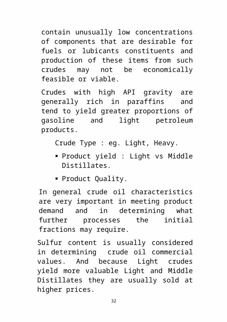
restrictive characteristics, because they require less specialised processes than that needed for the production of the same products from many cude oil types. Others may contain unusually low concentrations of components that are desirable for fuels or lubicants constituents and production of these items from such crudes may not be economically feasible or viable.
Crudes with high API gravity are generally rich in paraffins and tend to yield greater proportions of gasoline and light petroleum products.
Crude Type : eg. Light, Heavy.
Product yield : Light vs Middle Distillates.
Product Quality.
In general crude oil characteristics are very important in meeting product demand and in determining what further processes the initial fractions may require.
Sulfur content is usually considered in determining crude oil commercial values. And because Light crudes yield more valuable Light and Middle Distillates they are usually sold at higher prices.
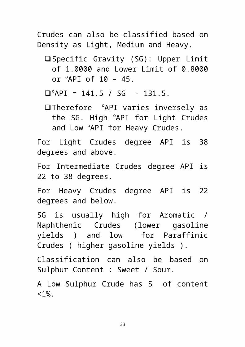
Crudes can also be classified based on Density as Light, Medium and Heavy.
Specific Gravity (SG): Upper Limit of 1.0000 and Lower Limit of 0.8000 or oAPI of 10 – 45.
oAPI = 141.5 / SG - 131.5.
23

Therefore oAPI varies inversely as the SG. High oAPI for Light Crudes and Low oAPI for Heavy Crudes.
For Light Crudes degree API is 38 degrees and above.
For Intermediate Crudes degree API is 22 to 38 degrees.
For Heavy Crudes degree API is 22 degrees and below.
SG is usually high for Aromatic / Naphthenic Crudes (lower gasoline yields ) and low for Paraffinic Crudes ( higher gasoline yields ).
Classification can also be based on Sulphur Content : Sweet / Sour.
A Low Sulphur Crude has S of content <1%.
Medium Sulphur Crudes have S content of 1 – 3% and
High Sulphur Crudes have S content >3%.
Sweet Crudes have premium prices.
PHYSICAL SEPARATION
The crude in the ground is usually sandwiched between a water layer below it and Asssociated Natural gas layer above. The dissolved gas pressure propels the crude to the surface where it is subjected to dewatering, solid removal and gas recovery before being made ready for sale. The Base Sediment and Water ( BS&W ), usually 1 – 3%, is one of the major market specifications. Others are the SG, API Gravity, Viscosity, Asphaltene and Wax contents ( tranportation consideration ), Hydrocarbon
24

types , Organic acids, Sulfur content ( Process considerations ), etc.
TRANSPORTATION
Crude oil is normally transported from the field storage tanks through pipeline to the loading terminal then to barges or ocean liners to the importer destination and from a receiving Jetty and another pipeline to storage tanks from where it is pumped again through pipeline to the Refinery and finally to the Process Units.
There is usually a designated custody transfer point where quality and quantity are agreed on apart from other shipping documentations for financial purposes.
INITIAL AND FURTHER USES
The primary use of crude oil, before the advent of motor car, was mainly for kerosene product to illuminate lamps. With Industrial Revolution came mechanization and wider uses for crude oil thereby accelerating the development of complex Petroleum Refining and Petrochemicals Process Technology.
Now increasing demand for energy and environmental concerns are the forces driving Technology.
Main driving force: relatively cheap source of Energy. The world is 87% dependent on Fossil Fuels: Oil, Gas and Coal as primary energy sources.
Oil - 37%; Gas - 24%; Coal - 16%;
25

Non – Fossil Fuels - 14%.
• Nuclear Energy - 6.15%
• Hydro Energy - 6.11%
• Others (Wind, Solar, Biofuel) - 1.51%
To Date “ Petroleum energy is the most economical and efficient energy reserve for transportation fuels”.
REFINERY CRUDE DISTILLATION
PLUS REFORMING
PLUS CAT CRACKER
PLUS ALKYLATION
Product %Wt
Gas 1.0 7.0 2.4
Gasolines 23.5 33.4 38.0
Middle Distillates
13.5 11.8 11.8
Fuel Oil 62.0 46.1 46.1
Loss - 1.7 1.7
TOTAL 100.0 100.0 100.0
26
FUNDAMENTALS OF PROCESS ENGINEERING
27

CONTENTS
PROCESS
PROCESS VARIABLES
DENSITY, SPECIFIC GRAVITY AND API GRAVITY
FLOWRATES
MASS, MOLE, MASS FRACTION AND MOLE FRACTION
AVERAGE ( MEAN ) MOLECULAR WEIGHT
CONCENTRATION
PRESSURE
TEMPERATURE
TABLE OF EQUIVALENTS ( CONVERSION FACTORS )
VAPOR PRESSURE AND PARTIAL VAPOR PRESSURE
DALTON’S LAW OF PARTIAL PRESSURES AND RAOULT’S LAW
THEIR APPLICATION TO BINARY MIXTURES
CONCEPT OF MATERIAL BALANCE
FLOW SHEETS( CHARTS ) AND THEIR FEATURES
28

PROCESS
A Process is any change or a series of changes effected to achieve a given goal.
The change may be chemical or physical and generally there are two sides to a process : Input ( Feed ) and Output (Product ).
A process can also have many stages, each being carried out in a Unit which has its own input and output.
A process can also be a Batch process in which inputs are rapidly feed to a tank and outputs (products) and unused feeds removed sometime later when the system has come to an equilibrium.
A continuous process involves movement of input species and outputs species continuously throughout the duration of the process like in continuous distillation.
A semibatch process is neither batch nor continuous. An example is slow blend of several liquids into a tank from which nothing is being removed at least temporarily.
Process Design involves developing a process flow diagram which indicates the amount, compostion and conditions of both the input stream(s) and output stream(s).
Process Operations is the daily routine monitoring of the processes to ensure that input and output rates are as
29

designed and output has the specified properties, that is, is on-spec or meets specifications.
Important variables in design and operations are :
Density(ρ) which relates the mass and volume of a given quantity of a substance.
Specific gravity ( SG ) relates the density of a substance to that of a reference substance, usually water, at a given condition and since it is a ratio it has no dimension.
Density of water at 4oC = 1.000gm/cm3
= 1000kg/m3
= 62.43lb(m)/ft3
The density of any liquid or solid in g/cm3 is numerically equal to its specific gravity.
FLOW RATES : This is usually applied to fluids ( liquids and gases ) and can be mass flow rate ( kg of fluid/sec ) or volumetric or cubic flow rate ( m3/sec ). The fluid density is used to convert one to the other. Flow rates are normally measured with a Rotameter or an Orifice meter using the difference in pressure between the upstream and downstream of an orifice plate.
MOLECULAR WEIGHT AND MOLE : The molecular weight of any substance is the summation of the atomic weights of the constituent elements.
The mole is a given mass divided by the molecular weight. Hence 1gm-mole or simply mole of a substance is the mass, in gm, that is equal to its molecular weight.
30

Other ways of expression are kg-mole(kmole), lb-mole, ton-mole etc.
In general if the molecular weight is “M”, then there is Mkg/kgmole, Mgm/mole or Mlb(m)/lbmole.
NB : 1gm-mole of any substance contains 6.02x10²³
( Avogadro Number ) molecules of the substance.
454gm = 1lb(m)
1mole of gas occupies 22.4litres @ STP
Mass flow rate can readily be converted to
Molar flow rate by dividing the mass flow
by the molecular weight.
MASS FRACTION, MOLE FRACTION AND AVERAGE MOLECULAR WEIGHT :
These terms are used to define the composition of mixture of substances.
The mass fraction of component A (aA) = Mass of A / Total Mass of all components.
The mole fraction of component A ( xA ) = Moles of A / Total Moles of all components.
It is possible to convert one to the other .
Consider a gas mixture with the composition( mass fraction) :
O = 20%, Steam = 63%, CO2 = 17%.
Assumig a total mass of 100kg gives
31
O = 0.2x100kg = 20kg, mole = 20/32 = 0.63
H2O(v) = 0.63x100kg = 63kg, mole = 63/18 = 3.5
CO = 0.17x100kg = 17kg, mole = 17/28 = 0.61
Total moles = 0.63 + 3.5 + 0.61 = 4.74
Mole fraction for O = 0.63/4.74 = 0.133
Mole fraction for steam = 3.5/4.74 = 0.738
Mole fraction CO = 0.61/4.74 = 0.129
The Average / Mean Molecular Weight ( Ma ) of a mixture is given by the equation :
If x1 is the mole fraction of one component with molecular weight M1 then
Ma = x1M1 + x2M2 + x3M3+ -------------- + xiMi
And if a1 is the mass fraction then
1/Ma = a1/M1 + a2/M2 + a3/M3 + --------- ai/Mi
CONCENTRATION
Concentration can be expressed as mass concentration or molar concentration
The mass concentration of component in a mixture or solution is its mass per unit volume of the mixture or solution , that is, gm/cm3, lb(m)/ft3 or kg/m3.
The molar concentration is the number of moles / unit volume; gmole/cm3, kmol/m3 or lbmol/ft3.
The Molarity of a solution is the number of moles of the solute / litre of solution.
32
Mass or molar concentration can be used to determine sample volume and mass or molar flow rates and total flow rate.
PARTS PER MILLION (ppm) AND PARTS PER BILLION (ppb) are used to express concentrations of substances present in minute amounts in a mixture of fluids. They can be mass ratio for liquids and molar ratio for gases and indicate parts (grams or moles) of the substance present / million or billion (grams or moles) of the mixture.Parts per thousand barrel(ptb) is used to express salt concentration in crude.
If yi is the fraction of component y in solution or the mixture then,
ppmi = 10-6yi and ppbi = 10-9yi
FLUID ( LIQUID OR GAS ) PRESSURE AND STATIC HEAD
Pressure is defined by the quotient of Force and the Area on which the force is exerted, that is , P = F/A. The common units are lb/in2 (psi), dynes/cm2 or N/m2 = 1Pascal(Pa).
The pressure exerted by a column of a liquid at the bottom of the container is given by :
P = Ptop + ρgh where g = gravitation acceleration and h = column height.
If Ptop = 0, then P = ρgh and since ρ and g are constant, then P α h.
33

The pressure exerted by a height of a fluid is called the Head of the fluid, which for water is 0.433psi since the density for water is 62.4lb/ft3(62.4/12 x 12).
Pressure is usually measured with Bourdon tubes, bellows, diaphgram or more commonly with a Manometer.
Pabsolute = Patmos + Pgauge.
TEMPERATURE
Temperature is a measure of the average energy of motion(kinetic energy) of the atoms or molecules of a substance which can be measured indirectly using some physical property which is temperature dependent in a known and precise way. For example expansion or volume change of a given mass of fluid in the Thermometer, electrical resistance of a conductor in a Resistance thermometer, voltage developed at the junction of two dissimilar metals in the Thermocouple or the radiation spectrum in the Pyrometer.
Temperature scale is developed in an arbitrary way by giving values to two measurable temperatures that are readily reproducible, e.g., 0 value for the freezing point and BP at 1bar, 100 value thereby giving value to the length of a unit temperature interval called a degree as 1/100 as the distance between the two specified points on the scale. A degree is therefore both a temperature and a temperature interval.
As a consequence we have the following temperature scales :
34

Celsius or Centigrade scale has 0o and 100o as the reference points.
Fahrenheit has 32o and 212o as the reference points.
Absolute Zero (the minimum temp that can be theoretically attained) is -273.15oC on the Celsius scale and -459.67oF on the Fahrenheit scale.
The Kelvin(K) and the Rankine(R) Scales have absolute Zero with 0o value and the value of a degree is the same as on the Celsius scale for K and Farenheit for R scales respectively.
The conversion of one to the other are as follow ;
K = oC + 273, R = oF + 460, oF = 1.8oC + 32.
VAPOR PRESSURE AND PARTIAL VAPOR PRESSURES
If a liquid like water is kept in a sealed container, a certain amount of it will evaporate to form vapor which will exert a pressure like any gas does and as long as the temperature remains the same an equilibrium (Evap = Cond) is soon established between the liquid phase and the vapor phase. The vapor pressure thus established depends on the nature of the fluid and is a constant at any given temperature and is called the saturated vapor pressure (simply VP) of the fluid. For example the VP of water @ 25oC is 23.76mmHg (0.46psi) and 760mmHg (14.7psi) @ 100oC. It is obvious from these values that VP is temperature dependent(See Attachment – Graph of VP vs Temp for some HCs).
35

As the container above is heated, more and more liquid evaporates and the VP rises. However as long as the VP is maintained, the liquid exhibits no further tendency to evaporate into the gas phase.
At a lower pressure, liquid will evaporate while at higher pressure vapor will condense till another equilibrium is established.
VP is therefore a measure of the tendency of atoms or molecules to escape from the liquid or solid body.
The atmospheric Boiling Point of a liquid is the temperature at which its VP equals the surrounding atmospheric pressure and is called its Normal Boiling Point. The higher the VP at a given temperature, the lower the BP of the liquid.
NB : Evaporation is accompanied by Heat absorption and Condensation by Heat release and for a pure substance, Heat absorbed at evaporation is numerically equal to the Heat released at condensation at a constant temp.
DALTON’S LAW OF PARTIAL PRESSURES
Different gases or vapors inside one container diffuse or mix rapidly and each exerts a pressure as if it alone occupies the total space in the container. The pressure thus exerted is called the partial pressure of the component and is a measure of the thermodynamic activities of its molecules.
Gases will always flow from a higher P to a lower P and the larger the ∆P, the faster the flow. Hence gases
36

dissolve, diffuse and react according to their partial pressures and not necessarily according to their concentration in a gas mixture.
John Dalton(1801) propounded his law of partial pressures which states that at constant temp., the total pressure (PT) exerted by a mixture of gases in a definite volume is equal to the sum of the individual pressures each gas would exert if it alone occupies the same total volume : PT = p1 + p2 + p3 + ------------- + pi (1).
It has been proved in Physical Chemistry that for Ideal gas mixtures and for any component i that :
Pi = yiPT (2) where pi = partial presure and yi = mole fraction of the component. In other words, the PP of any component in gas mixture is equal to the product of its mole fraction and the total pressure( PT ) exerted by the mixture.
Equation (2) above is very important in Chemical and Chemical Engineering calculations since it relates the PP of a gas to the total pressure, which is easily measured, of the gas mixture and the mole fraction relates the moles of a given component to the total number of moles of the gases present.
It is easily proved that the summation of mole fraction is equal to 1 (one) in liquid and gas mixtures and solutions.
RAOULT’S LAW
This law deals with the behavior of liquid mixture.
The VP of an Ideal liquid solution is dependent on the VP of each component and the mole fraction of the
37

component in the solution. Once the components in solution are at equilibrium and if they are volatile and completely miscible and non-reactive, then the PP of a component equals the product of its mole fraction in the mixture and the VP of the pure component :
pi = xiPio (3)
Hence as the number of the components increases, the individual VP decreases since mole fraction of each component decreases with each additional component.
Consider two volatile and completely miscible liquids A and B in a sealed container.
By Raoult’s law :
pa =xaPao and pb = xbPb
o ( 4- 1 & 4-2)
And by Dalton;s law, the total VP exerted above the solution will be
PT = pa + pb (5)
= xaPao + xbPb
o (6)
But xa + xb = 1 or xa = 1 - xb or xb = 1- xa (7)
Hence PT = Pao(1-xb) + xbPb
o
= xb(Pbo – Pa
o) + Pao (8)
Similarly,
PT = xa(Pao – Pb
o) + Pbo (9)
For any system at a given temperature; Pao and Pb
o are constant, hence a plot of PT vs xb in (8) gives a straight line with PT = Pa
o at xb = 0 and PT = Pbo at xb = 1.
38

The dotted lines in the Attachment( Fig 8.3) are plots of pa = xaPa
o and pb = xbPbo of each component and these
vary linearly from pa = Pao for xa = 1 and Pb
o = 0 for xb = 0 to Pa
o = 0 and pb = Pbo at xb = 1.
The PT for each concentration, say x’, lies on the straight line joining Pa
o and Pbo and is also the sum of the PP
ordinates.
LIQUID - VAPOR COMPOSITION
If yb is the mole fraction of B in the vapor phase above the solution with composition xb then, yb = pb/PT by
Dalton’s law and pb = xbPbo by Raoult’s law.
Therefore yb = xbPbo / xb(Pb
o – Pao) + Pa
o from eqn 8.
The above relation shows that a definite vapor composition corresponds to a definite liquid composition and that yb can not be equal to xb except Pa
o
= Pbo and then there is no longer a mixture but one
component .
Using this last equation, a VP vs Vapor compositon graph can be constructed showing the composition of vapor corresponding to a given liquid composition. We can now relate these theoretical assumptions to the behavior of a binary mixture of two HCs in the Attachments already with you. This is the basis for both batch and continuous distillations.
39

MASS OR MATERIAL BALANCE
A mass or material balance is an application of the Law of Conservation of Mass to the analysis of physical or chemical systems. By accounting for materials entering and leaving a system, mass flows can be identified which might have been unknown or difficult to measure without this technique as will be illustrated in the Sugar Plant later.
The exact techniques used in the analysis of the system depends on the context of the problem but all revolve around conservation of mass, that is , that matter can not disappear or be created spontaneously.
Closely related and complementary analysis techniques include Energy Balance and the somewhat more complex Entropy Balance.
The general form for Mass Balance is The Mass that enters a system must, by conservation of mass, either leave the system or accumulate within the system.
Mathematically represented for a system without a chemical reaction is as follows :
INPUT = OUTPUT + ACCUMULATION ---------------(1)
In the absence of a chemical reaction, the amount of any species flowing in and out will be the same giving rise to an equation for each species in the system since it must be accounted for. However if this is not the case, then the mass balance equation must be amended to allow for the generation or depletion of any chemical
40

species. Mass is negative for depletion and positive for generation.
What has been stated above is true for both batch operation and also for continuous operation over any chosen time interval.
The amended form is :
INPUT+GENERATION = OUTPUT+ACCUMULATION – (2)
This simplifies to (1) if generation is 0.
In the absence of a nuclear reaction, the amount of species flowing in and out must be the same, even in the presence of a chemical reaction.
The boundaries of the system must be well defined.
Mass balances can be taken over systems in multiple
stages.
Mass balances can be simplified with the assumption
of steady state where accumulation is Zero.
Mass and Energy balances are very important in an industry. Material balances are fundamental to the control of processing, especially in the control of yields of products.
The first material balances are determined in the exploratory stages of a new process, improved on with Pilot plant experiments when the process is being planned and tested, checked out when the plant is commissioned and then fine-tuned and maintained as a control instrument as production continues. When
41

changes occur in the process, the material balances need to be determined again.
Material and Energy balances can be simple, at times can be very complicated, but the basic approach is general. Experience in working with simpler systems such as individual unit operations will usually help develop the ability to extend the method to the more complicated situations.
The increasing availability of computer programs has made it possible to set up and manipulate very complex mass and energy balances quite readily and therefore be used in everyday process management to maximise yields and minimise costs.
BASIC PRINCIPLES
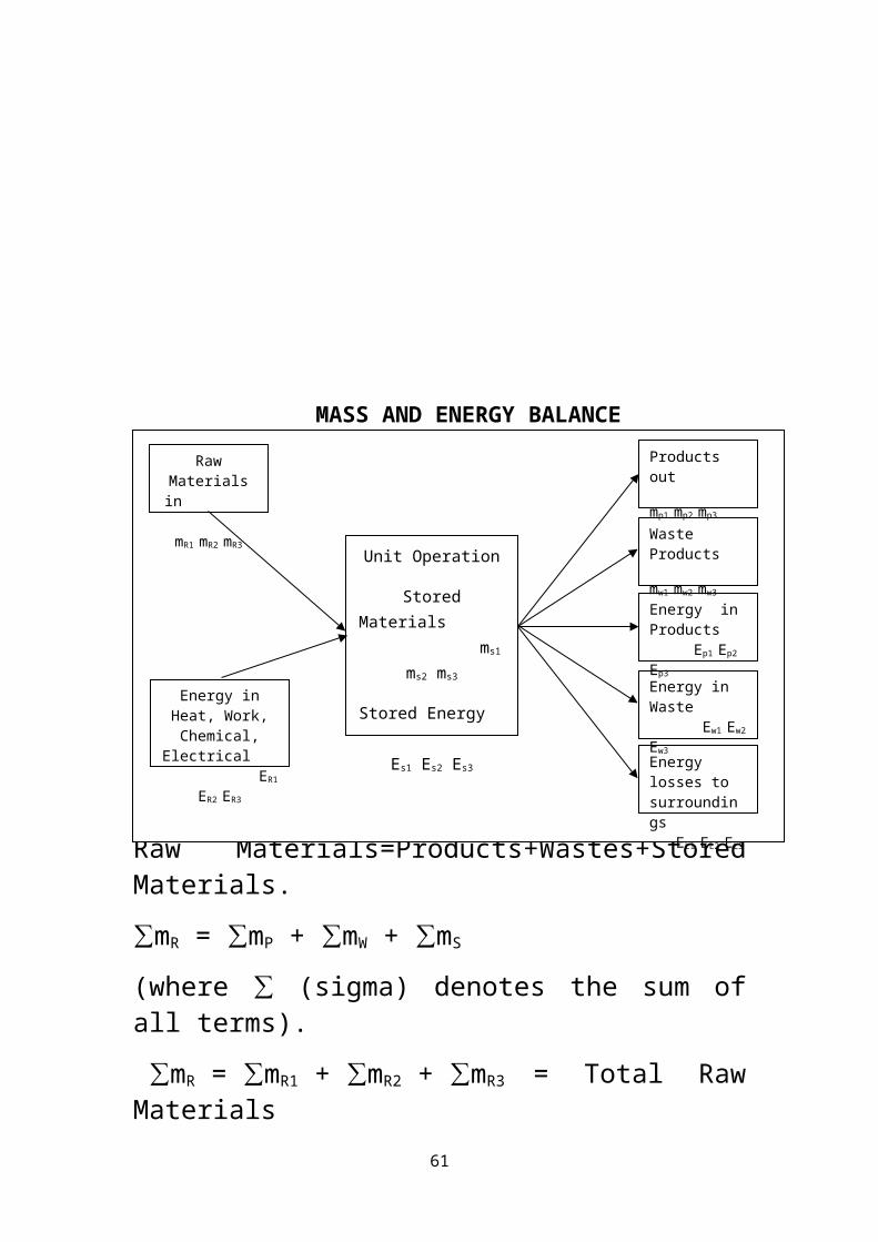
If the Unit operation, whatever its nature, is seen as a whole then it may be represented diagramatically as a box as shown on the next page. The mass and energy going in must balance with the mass and energy coming out. Our focus, however, is Mass balance.
42

Mass In = Mass Out + Stored Materials.
Raw Materials=Products+Wastes+Stored Materials.
∑mR = ∑mP + ∑mW + ∑mS
(where ∑ (sigma) denotes the sum of all terms).
∑mR = ∑mR1 + ∑mR2 + ∑mR3 = Total Raw Materials
∑mP = ∑mP1 + ∑mP2 + ∑mP3 = Total Products.
∑mW = ∑mW1 + ∑mW2 + ∑mW3 = Total Waste Products
∑mS = ∑mS1 + ∑mS2 + ∑mS3 = Total Stored Products
And, that is, Total RM = Total P + Total W + Total SM.
If there are no chemical changes occuring in the plant, the Law of Conservation of Mass will apply to each component in the system and so for component ‘A’:
mA in entering materials = mA in exit materials + mA stored
For example, in Sugar producing plant, if the total amount of sugar coming in is not equalled by total of purified sugar and sugar in the waste liquors, then
43
Unit Operation
Stored Materials ms1 ms2 ms3
Stored Energy Es1 Es2 Es3
Products out
mp1 mp2 mp3
Waste Products
mw1 mw2 mw3
Energy in Products Ep1 Ep2 Ep3
Energy in Waste Ew1 Ew2 Ew3
Energy losses to surroundings EL1 EL2 EL3
Raw Materials in mR1 mR2 mR3
Energy in Heat, Work, Chemical, Electrical
ER1 ER2 ER3
MASS AND ENERGY BALANCE

something is wrong. Sugar is either being burned (chemically changed) or accumulating in the plant or going unnoticed down the drain somewhere. In this case,
mA = mAP + mAW + mAU
where mAU is the unknown loss and needs to be identified. So we now have :
RawMat = Products + Waste Products + Stored Products + Losses
where Losses are the unidentified materials
The first step is to look at the three basic categories : materials in, materials out and materials stored. Then consider the materials in each category to determine if they are to be treated as a whole, a gross mass balance or whether various constituents need to be treated separately and if so which one. For example, it might be to take dry solids as opposed to total material; meaning separation into two groups of materials; Non-water and water. More complete dissection can separate out into chemical types.
The choice and detail depend on the reason for making the balance and on the information that is required.
A major factor in industry is, of course, the value of the materials and so, expensive raw materials are more likely to be considered than cheaper ones and products than wastes.
Having decided which constituent to be considered, the basis for the calculations has to be decided. This might be some mass of raw material entering the process on a
44

batch system or some mass per hour in a continuous process. It could be some mass of a particular predominant constituent (a given or assume mass of flour entering in a bakery) or some unchanging constituent, such as in combustion calculations with air where it is helpful to relate everything to the inert Nitrogen component.
Sometimes it is not important what basis is chosen and in such cases, a convenient quantity such as the total raw materials into one batch or passed in per hour to a continuous process are often selected. Having selected the basis, then the unit may be chosen such as mass or concentration which can be weight or molar .
Material balances can be based on total mass, mass of dry solid or mass of a particular component as shown in the calculations examples below.
45

PROCESS FLOW CHARTS
The identification and drawing up a unit operation /process is prerequisite for material balance and is explained below.
Flow charts are schematic representation of the production process , involving various input resources, conversion steps and output and recycle streams.
The process flow may be constructed stepwise i.e. by specifying the input / output / waste at each stage of the process as shown in the figure below :
Input of the process could include raw materials, water, steam, etc,
Process Steps should be sequentially drawn from raw materials to finished product. Intermediates and any other byproducts should also be represented as well as operating parameters such as temperature, pressure, %concentration, etc.
The flow rate of the various streams should be stated in the appropriate units ( m3/h, kg/h, lb(m)/ft3, moles/h, etc ) . Batch process should include total cycle time.
46
PROCESS
STEP -1
PROCESS
STEP -2Inputs
Inputs
Wastes
Wastes
OutputPROCESS FLOW CHART

Wastes or Byproducts could include solids, water, etc. For each process step ( unit operation ) as well as for an entire plant mass balance should be drawn.
47

MASS BALANCE CALCULATIONS
Example 1
Using mass balance to check the results of an air pollution monitoring study.
A fabric bag filter is used to remove dust from an inlet gas stream so that the outlet gas stream meets the required emission standards say in a cement or fertilizer plant
During the study, the inlet gas flow to the bag is 169,920m3/h with a dust loading of 4577mg/m3. The filter outlet is 185,040m3/h and the dust loading is 57mg/m3.
What is the maximum quantity of ash removed / hour from the bag filter hopper based on these test results ?
Solution
Based on dust balance :
Mass In = Mass Out.
Inlet gas stream dust = Outlet gas stream dust + Hopper Ash.
48
FABRIC FILTER169920 m3/hr
4577 mg/Nm3
185040 m3/hr
57 mg/Nm3
ASH = x kg/hr
DUST REMOVAL

Calculate Inlet and Outlet dust quantities in kg/h.
Inlet Quantity = 169920m3/h x 4577mg/m3 x 1/106kg/mg
= 777.7kg/h
Outlet Quantity = 185040m3 /h x 57mg/m3 x 1/ 106 kg/mg
= 10.6kg/h
Ash Quantity Reqd to be removed /h is given by
Hopper Ash = Inlet dust quantity – outlet dust quantity
= 777.7kg/hr - 10.6kg/h = 767.1kg/h
Example 2
Consider a slurry flowing into a settling tank to remove the solids which are collected at the bottom of the tank using a conveyor belt partly submerged in the tank and water exit via an overflow pipe.
There are thus two species; solids and water which concentrate in each output stream, ie. Water to solid ratio being higher in the overflow than in the inlet and the solids concentration at
49

the exit of the belt is also higher than at the inlet as indicated in the sketch.
Assume a steady state and a non-reactive system, accumulation is zero
Analysis :
Analysis of slurry gives a mass composition of the inlet: 50% solid and 50% water with a mass flow rate of 100kg/min and combined solid and water outlet is 60kg/min.
Slurry removal efficiency of the tank is 60%.
What is the water/solid amounts in each output stream ?
Solution
Since efficiency is 60%, then the water outlet will contain
40% x 50%solids x 100kg/min = 20kg/min of solidsThe amount of water leaving with solids on the conveyor
belt : ???Example 3
Skim milk is made by removing some fat from whole milk. The skim milk on analysis has the following composition :
90.5% Water, 3.5% Protein, 5.1% Carbohydrate,
0.1% Fat and 0.8% Ash.
Given that the whole milk contains 4.5% Fat and that only fat was removed and no losses, calculate the composition of the original whole milk .
50
SKIMMERINPUT: WHOLE MILK
FAT = 4.5%
OUTPUT: SKIM MILK
WATER = 90.5%, PROTEIN = 3.5%, FAT = 0.1%, ASH = 0.8%, CARBOHYDRATE = 5.6%.
Solution
Basis : Assume 100kg of skim milk.
Fat content = 0.1%
Let the fat removed from the whole milk = x kg
Therefore total original fat = ( x + 0.1 ) kg
Total original mass = ( 100 + x ) kg
Since the original fat is 4.5%, then
( x + 0.1)/(100 + x) = 4.5/100= 0.045 kg and this gives
X = 4.6kg.
And total original mass = 100kg + 4.6kg = 104.6kg
Hence the composition of the whole milk will be :
Fat = 4.5%, 90.5/104.6% = 86.5%water,
3.5/104.6% = 3.3%protein, 5.1/104.6% = 4.9% carbohydrate
And 0.8/104.6% = 0.8%ash.
Example 4
A common salt solution was prepared by dissolving 20kg of salt in 100kg of water to give a solution with a density of 1323kg/m3.
Calculate salt concentration in solution as :
a) weight fraction, b) weight/volume fraction, c) mole fraction and d) molar concentration.
Solution
a) Weight fraction : 20/ 120 0.167, %wt/wt = 16.7%
b) Weight/volume : From the density, 1m3 of soln weighs
51

1323kg, hence 1323kg of solution contains
20x1323kg salt/120 = 220.5kg/m3
Wt/volume fraction = 220.5/1000 = 0.2205 = 22.05%
c) Moles of water = 100/18 = 5.56
Moles of salt = 20/58.5 = 0.34
Total moles = 5.9
Hence mole fraction of salt = 0.34/5.9 = 0.058
d) Molar conc ( M ) = 220.5/58.5 = 3.77moles/m3
Note : For dilute solutions, mole fraction of solute approx = moles of solute/moles of solvent. This applies to solid/liquid mixtures. For solid/solid mixture, concentrations are normally expressed as simple weight fractions.
With gases concentrations are primarily expressed as weight/unit volume or as partial pressures using the Gas Law :
pV =nRT as illustrated below; R = 0.08206m3atm/moleK and 1 atm = 100 kPa
Wt conc = nM/V, M = Gas molecular wt.
Example 5
Air consists of 77%wt nitrogen and 23%wt oxygen.
Calculate : a) mean molecular wt of air.
b) mole fraction of oxygen and
c) concentration of oxygen in mole/m 3 and kg/m3 at 25oC and 1.5 atm. Use R value supplied above.
Solution
52

Basis : 100kg of air
a) Moles of N = 77/28 = 2.75, moles of O = 23/32 = 0.72
Total moles = 2.75 + 0.72 = 3.47
Mean molecular wt of air = 100/3.47 = 28.8
b) Mole fraction of O = 0.72/3.47 = 0.21
c) pV = nRT, R = 0.08206m3atm/moleK, T = 298K, V = 1m3 and p= 1.5atm
Hence n = pV/RT = 1.5 x 1/ 0.0820 x 298 = 0.061
Wt of air = 0.061 x mean mol wt = 0.061 x 28.8 = 1.76kg/m3
Wt of O = 23% x 1.76 = 0.4kg/m3 = 0.4/32= 0.013mole/m3
When a gas is dissolved in a liquid, the gas mole fraction in the liquid is calculated using the Gas law to obtain the number of moles. The total volume is usually taken as that of the liquid and then moles of liquid is determined.
Example 6
In the carbonation of a soft drink, the total amount of CO2 reqd is equivalent to 3 volumes of gas to one volume of water at 0oC and 1 atm P.
Calculate a) mass fraction and b) mole fraction of CO2 in the soft drink, ignoring all other components except CO2 and water.
Solution
Basis : 1m3 of water = 1000kg ( Density )
Therefore volume of carbon dioxide = 3m3
From Gas law, pV = nRT
Hence n = 3 x 1 / 0.08206 x 273 = 0.134
Wt of carbon dioxide = 0.134 x 44 =5.9kg
53

Mass fraction = 5.9 / 1000 + 5.9 = 5.9 x 10⁻³
Mole fraction = 0.134/ ( 1000/18 + 0.134 ) = 2.41 x 10⁻³
CONTINUOUS PROCESSES
In continuous processes, time enters into consideration and balances are related to unit time. If material holdup is constant both in mass and composition, then quantities entering and leaving in different streams in unit time are constant and a mass balance can be written on this basis. Such analysis assumes the process is in a steady state, i. e., flows and quantities held up do not change with time.
Example 7 : MILK CENTRIFUGE – A CONTINUOUS PROCESS
35,000kg of whole milk with 4% fat is to be centrifuged in 6 hours into skim milk containing 0.45% fat and cream with 45% fat. What will be the flow rates of the two output streams from the continuous centrifuge to accomplish this separation ?
Basis : 1 hour’s flow of whole milk.
Mass In :
Total mass of whole milk/hr = 35,000/6kg = 5833kg
Fat content + 0.04 x 5833kg = 233kg
Hence water and others = (5833 – 233)kg = 56,000kg
Mass Out :
If the mass of cream is x kg then its total fat = 0.45x kg
54
CENTRIFUGEINPUT: WHOLE MILK
35, 000kg, FAT = 4%
OUTPUT
SKIM MILK WITH 0.45% FAT.
CREAM WITH 45% FAT.6 HOURS

Therefore mass of skim milk = (5833 – x) kg and its total fat content is 0.0045(5833 – x)kg
Mass Balance On Fat
Fat In = Fat Out
233 = 0.0045(5833 – x ) = 0.45x
x = 465kg
Hence the flow of cream = 465kg/hr and
Skim milk = (5833 – 465)kg/hr = 5368kg/hr
Example 8
A srubber is used to remove fine particle or dust from the inlet gas stream with a spray or a liquid, typically water, so that the outlet gas stream meets the required process or emission standard ( see figure below )
55

How much water must be continually added to wet the scrubber in order to keep the unit running ?
Each stream is identified by a number within a diamond symbol. Stream 1 is the recirculation liquid flow stream back to the scrubber at 4.54m3/hr. The mass flow liquid being withdrawn for treatment and disposal ( stream 4 ) is 0.454kg m3/hr
Assume inlet gas stream ( #2 ) is completely dry and the oulet stream ( #6 ) has 272.16kg/hr of moisture evaporated in the scrubber. The water being added is stream #5.
Solution
Step 1 : Set up material balance around the scrubber
Convert form kg/hr to m3/hr for stream #6 to keep units constistent; 272.16kg/hr x m3/1000kg = 0.272m3/hr.
Then set up MB equation and solve for stream #3, viz :
InputScrubber = OutputScrubber
Stream 1 + Stream 2 = Stream 3 + Stream 6
4.54 m3/hr + 0 = y m3/hr + 0.272 m3/hr
Hence Stream 3 ( y m3/hr ) = ( 4.54 – 0.272 ) m3/hr
= 4.27m3/hr
Step 2 : Do MB around the recirculation tank and solve for
Stream 5.
InputTank = OutputTank
Stream 3 + Stream 5 = Stream 1 + Stream 4
4.27m3/hr + x m3/hr = 4.54m3/hr = 0.454m3/hr
Hence Stream 5 = 4.994m3/hr - 4.27m3/hr
56

= 0.724m3/hr
If it is to calculate only the makeup water , Stream 5, then
Stream 5 = ( 0.454 + 0.272 ) m3/hr = 0.73m3/hr
One of the key steps in solving this Example is drawing a simple sketch of the system.
This is absolutely necessary so that it is possible to conduct material balances. Drawings are a valuable first stpe when solving a wide variety of porblems, even one that looks simple.
Drawing is a very useful way to summarise what we know and what we need to know. It helps visualise the solution.
If the problem involves dimensional quantities, the dimensions should be included on the sketch. They serve as reminder of the need to convert the data into consistent units
57

FUELS REFINING PROCESSES
58

CONTENTSPHYSICAL SEPARATION PROCESSES
CRUDE OIL DESALTING
CRUDE DISTILLATION
CRUDE DISTILLATION COLUMN INTERNALS
DIFFFERENT COLUMN OVERHEADS AND PRODUCT DRAW OFFS.
STABILISATION, STRIPPING AND SPLITTING
VACUUM DISTILLATION
CONVERSION PROCESSES :
QUALITY IMPROVEMENT :
HYDROTREATING
CATALYTIC REFORMING
ISOMERISATION
DECREASING AVERAGE MOLECULAR WEIGHT:
CRACKING - THERMAL AND CATALYTIC, HYDROPROCESSING ( HYDROGENATION – HYDROTREATING, HYDROCRACKING )
INCREASING AVERAGE MOLECULAR WEIGHT:
ALKYLATION AND DIMERISATION
59

AUXILLARY PROCESSES –
HYDROGEN GENERATION
STEAM REFORMING AND
SHIFT CONVERSION
AMINE TREATMENT
SULFUR RECOVERY
60
PHYSICAL SEPARATION PROCESSES
61

CRUDE OIL DESALTING
This is the first process crude oil is subjected to in the refinery. Crude oil often contains water, inorganic salts, suspended solids, and water-soluble compounds of some metals.
Desalters are sized to allow water and oil to settle and separate according to Stoke’s law.
Desalting process helps to remove contaminants from crude and hence helps to reduce corrosion, plugging and fouling of equipment and to prevent poisoning the catalysts in downstream processing units and therefore improves on the reliability of these units and reduces total cost of refinery operation.
The major contaminants – The contaminants-salt, water, added chemicals and solids if not removed from the crude can cause serious damage to distillation equipment, limit on-steam time, and cause inefficient operation throughout the crude distillation unit. Specific effects resulting from the salts in the crude are;
(a) hydrolysis to hydrochloric acid which will cause severe corrosion in the crude distillation tower and lines;
(b) the salt acts as a catalyst for coke formation in furnace tubes and transfer lines;
(c) salts and solids are deposited on heat exchanger and furnace tubes causing plugging, reduced heat transfer rates in the exchangers and “hot spots” in the furnace tubes.
62

Residual products such as asphalt and fuel oils are contaminated when effective desalting of the crude is not accomplished.
This is due to the fact that inorganic salts remaining in the crude tend to concentrate in the distillation residuums. Such contamination in fuel oils can cause clogging of burner or the deposition of slag on furnace tubes and brickwork of boiler installations. The most efficiently designed refinery will suffer from corrosion and lost on-steam time if effective desalting equipment does not function continuously.
Consequently, the separation of crude oil, salt, water and other impurities has been a major refining problem.
One of the early methods of separating crude oil from entrained impurities consisted primarily of settling. Improvement was made by heating the oil before settling. Sometimes the addition of chemical to the mixture before settling gave further improvements. However, obtaining consistently good results was difficult and practically all refiners now use electrical desalting equipment.
The major contaminants are :
-Chloride salts of Na, Ca and Mg
-Solids ; iron sulfides, sand, silts, clay from drilling mud mostly responsible for exchanger and heater fouling.
-Water as brine from the oil field (Spec. 1 – 3% in water). High BS&W reduces feed rate, increases energy cost,
63

contributes to downstream equipment corrosion and increased waste water production
Benefits of desalting are:
-Protection of downstream equipment
-Reduces corrosion and hence maintenance costs
- Maximizes throughput
-Extends run length
-Stabilises unit operations
-Reduces energy cost
-Reduces slops treatment cost
Desalting Process:
Crude-oil desalting is usually by chemical injection and electrostatic separation or precipitation.
a. Electrical desalting is the application of high-voltage electrostatic charges to concentrate suspended water globules in the bottom of the settling tank ( Desalter).
b. Water and chemical surfactant (demulsifiers) are usually added to the heated crude, so that salts and other impurities dissolve into the water which then settles out.
64

PROCESS VARIABLES
(a)Water and salt content.
(b)Pressure drop across the mixing valve
©Chemical addition.
(d)Wash water rates 3 to 10 volume per cent based on crude oil charge.
(e)Settling time in accordance with stokes law.
(f)Temperature as determined by the viscosity of the oil.
(g)Alternating electric field.
(h)Pressure to keep the system from boiling.
(i)Desalter level.
(j)Ph which has effect on conductivity.
(k)Oleophobic impurities.
What can go wrong with desalting :
-Poor dehydration of the crude ( water carry over)
-Oil in desalter water ( oil carry over )
65

-Low voltage or high current
-Widely fluctuating voltage and current
66

REFINING PROCESSES - SEPARATION PROCESSES
ATMOSPHERIC DISTILLATION
The first step in crude oil refining is by a process known as Distillation during which the crude is separated into a number of streams called fractions, each one having a certain boiling range and a distinct name. The Crude Distillation Unit carries out this process.
Distillation Theory
A working knowledge of this topic is necessary in order to have an understanding of the Crude Unit operation.
When a mixture of liquids is heated to boil, the first vapors from the mixture almost always have a composition that is different from the composition of the liquid mixture.
“Distillation is process in which a liquid or vapour mixture of two or more substances is separated into its component fractions of desired purity by the application of and removal of heat.”
Distillation is the most common separation technique. It is used to separate mixtures by enrichment of phases which occurs with boiling and depends on materials having different boiling points. Any two liquids having the same boiling points can not be effectively separated by distillation.
67

The difference between liquid and vapor compositions is the basis for distillation operation as earlier discussed.
This is based on the fact that the vapor of a boiling mixture will be richer in the components that have lower boiling points ( higher volatilities ). Therefore, when this vapor is cooled and condensed, the condensate will contain more of the volatile components while the original mixture will contain more of the less volatile components.
Distillation columns are designed to achieve this separation.
Therefore, the important variables in distillation are composition, pressure and temperature. The boiling point of a mixture is determined by composition and pressure and since distillation is a boiling process, distillation pressure and temperature are not independent for a known composition.
For a binary system with a component boiling at 150oC and the second at 250oC, if the pressure and composition are known then the BP is fixed and must be between these two temperatures. For more complex mixtures, the composition can only be estimated within a certain range.
The dew point is the temperature at which saturated vapor starts to condense and the bubble point is the temperature at which the liquid starts to boil.
68

Crude stills are the first major process unit in the refinery. They are used to separate crude oils into fractions according to boiling points so that the downstream processing units will have feedstocks that meet their particular specifications.
Crude distillation consumes enormous amounts of energy, both in terms of cooling and heating requirements and can constitute 40% to 50% of plant operating costs.
Distillation Column
A distillation or fractionating column is a piece of equipment designed to separate liquid mixtures continuously by enrichment from boiling feature of liquid mixtures in a multistage manner by continuously boiling and condensing mixtures of different compositions at different temperatures.
The feed mixture comes into the column some where in the middle and products are removed from the top, along the side and the bottom. The bottom is heated while the top is cooled with cold liquid to create a
69

70

continuous temperature profile down the column for boiling and condensing. In normal operation, the pressure of the column is held constant and since every component boils at a certain temperature and pressure, and with the pressure set, an observation of the temperature will indicate where in the column a particular component is located.
Inside fractionating column are horizontal steel trays( see the figure below) with openings in them to allow vapors from the tray below to pass through the top tray and to bubble through the liquid that is held up on the top tray. On each tray the liquid boils and vapors are condensed at the temperature of that tray.
Each tray has overflow pipe called the down comer. When the liquid level on a tray reaches a certain height, the liquid spills over the edge of the down comer and drains the condensed liquids from each tray back to the tray below, where the higher temperature causes re-evaporation until the desired degree of product purity is reached. The downcomer might be a circular pipe or might be made of the column wall and a flat plate mounted vertically at one side of the tray. The top edge of the pipe or plate forms a Weir (usually about 2” high), the height of which determines the height of liquid on the tray.
Then side streams from certain trays are taken off to obtain the desired fractions.
71

Diameter and Height are proportional to vapour and liquid rates and number of streams or fractions to be withdrawn:
About 110ft : 30 trays and 4 streams / fractions
and 160ft : 50 trays and 6 streams / fractions.
Trays are usually spaced 12 inches ( 300mm ) to 24 inches ( 600mm ) apart.
Columns are generally higher and slimmer with lighter materials but shorter and wider for heavy ones.
72

Column internal arrangements and configurations differ depending on the service requirement and design consideration
The active area of a tray is about 70% of the tray and provides the contact between up flowing vapor rich fluid and counter flowing liquid while a settling portion known as the free area serves as a flow pulsation dampner. The space between the wall and the end of the tray is hollow to allow for down flowing liquid from one tray to another – the downcomer. A weir is used to create a little head of liquid on the tray to enhance liquid / vapor contact.
TRAY TYPES : There are three basic types performing same function but using different methods;
Bubble Cap Tray – most efficient because liquid / vapor contact is
73
DIAGRAM OF A TYPICAL TRAY

much enhanced but more susceptible to fouling and hence high maintenance cost.
Sieve Tray – the simplest form with little efficiency since there is no special arrangement for liquid / vapor mixing.
Valve Tray – differs from the sieve tray by arrangement of the holes. Movable covers are provided for the holes with a device restricting the movement of the cover to vertical movement in accordance with up flowing vapor rate.
74

The column has many trays. The vapor bubbling through the liquid on one tray comes from boiling on the tray just below. The vapor condenses because the liquid on a tray is cooler than the vapor from the tray below. The heat of the condensation step causes some vapor to be boiled off and this vapor in turn goes up to the next higher tray. Hence each tray carries out an enrichment (from the boiling step) and this is done on a continuous basis.
Column operation must be kept in balance. Product rates must be kept equal to the feed rate. Similarly, heat removal rates must be kept equal to heat input rate. The pressure has to be held constant so that temperatures can be used to estimate compositions. Pressure is controlled by balancing vapor input with output or condensation, which is balancing heat input and output.
The overall goal is to have the desired product composition. With the pressure constant, composition is indicated by temperature; the top or bottom temperature should be controlled to obtain the desired composition.
The important variables are the flows of liquid and vapor down and up the column compared to the feed flow rate. The higher the internal rates, up to a certain limit, the better the separation. In practice, this comes from adjusting the reflux or the reflux ratio. This is the amount of liquid returned to the top tray as compared to the feed flow rate or top product rate. Usually automatic controllers are used to adjust reflux rates in order to maintain the column temperature profile.
75

Process Variables
Crude oil is usually pumped from storage tanks to the Unit after ensuring that it is fairly dry from the BSW result. This is to minimize the chance of large amounts of liquid water entering the unit. If this occurs, the water will vaporize causing a high pressure drop in the column or possibly derail or damage the trays.
In order to reduce the unit operating cost, as much heat as possible is recovered from the hot streams from the column by heat exchange with the cold crude charge, which then goes to the Desalter. The crude, ex the Desalter, is then heated to the desired feed temperature in the Charge heater or Furnace. The Heater outlet temperature is called “Transfer Temperature or Coil Outlet Temperature ( COT)” and can vary from 600oF ( 315oC ) to 800oF ( 425oC ) depending on the crude oil feed.
The furnace supplies all of the additional heat input necessary to the column in excess to that supplied by the heat exchange train.
The crude oil exiting the furnace is in two phases and hence some of it on entering the Flash Zone of the column, at about atmospheric pressure, flashes into vapor which rises up the column while the remaining liquid residue drops downward. This flash is a very rough separation; the rising vapors from the flash zone still contain some heavy ends, which must be rejected into the bottoms while the descending liquid contains some light ends which must be stripped out.
76

The flashed vapors rise up the column counter-current to the Internal Reflux flowing down the column. The lightest materials of Naphtha range pass overhead and are condensed into an overhead receiver. Uncondensables leave the receiver as gases and can be recovered by compression as required.
The fractionator top temperature is good measure of naphtha end point and is controlled by returning some naphtha as reflux along with naphtha side cut to the top of the column. Increasing this reflux rate lowers the top temperature and decreases the rate of the net overhead product with a lower end point. This loss must be recovered from the Kero draw off tray and this will reduce the initial boiling point of the material from this tray.
External reflux from the top of the column ( overhead receiver ) moves downward against rising vapors. The light ends from it are re-vaporised and move towards the top while the heavy ends in rising vapors are condensed and move down the column. This creates an internal reflux stream flowing from the top all the way to the flash zone and becoming progressively heavier as it descends.
Products heavier than the net overhead are withdrawn from portions of this internal reflux stream. The end point of a side cut depends on the amount of liquid being withdrawn. If the side cut withdrawal is increased, the extra product is part of the material which was formerly flowing down the column as internal reflux. Since reflux flow to the tray below is now reduced,
77

heavier vapors can now rise to the tray above resulting in heavier product.
Therefore varying draw off rate is the way side cut end point specs are maintained.
The temperature of the draw off tray is a fair indication of the product end point and an experienced operator may increase/decrease his draw off rate to hold a constant tray temperature and hence keep product on-spec.
The degree of fractionation is generally judged by the relationship between ASTM distillation temperature at 95% volume of the lighter product and 5% volume of the adjacent heavier product. Some use IBP, which varies with stripping and EP or FBP.
If the ∆T > 0, it is called a Gap and shows good separation.
If ∆T < 0, there is an Overlap, a sign of poor separation.
Sometimes a gap is difficult to achieve and all one can do is to reduce the overlap as much as possible.
Fractionation can be improved by increasing reflux rate by an appropriate increase in the COT.
Reflux is the liquid stream returned to the column and helps to achieve two purposes : extraction of heat from the column while at the same time strips heavy ends from the up flowing fluid (vapors). It also purifies the distillate stream while providing column stability.
78

There may be occasions where internal reflux required for good separation is so great that if it was all supplied from the top, the top trays will flood. An “Intermediate Circulating Reflux or Side Reflux or Pump Around” solves the problem. Some internal reflux materials are withdrawn, pumped through a cooler or an exchanger and returned colder to a few trays higher in the column. This cold reflux condenses extra vapors to liquid and increase the internal reflux below the inlet point.
Sometimes a draw off tray is pulled dry, that is, product withdrawal rate is greater than internal reflux rate. The trays below become dry and no fractionation occurs. Then either reducing product withdrawal rate or increasing internal reflux by increasing the COT or reducing the rate at which the next lighter product is being withdrawn will correct the problem.
FACTORS AFFECTING COLUMN OPERATION :
The performance of a distillation column is determined by many factors :
-Feed Conditions:- The state and composition of the feed and presence of contaminants that can severely affect the vapor-liquid equilibrium.
-Internal liquid and fluid flow conditions ( reflux )
-State of the trays and or packings and
-Weather conditions especially in temperate areas.
79

Other factors include changing operating conditions and throughputs, imposed by changes in upstream conditions and changes in the demand for products. All of these plus associated control system should be considered at the design stages because once a column is built and installed, nothing much can be done to rectify the situation without incurring significant costs.
CRUDE DISTILLATION: (See Diagram Below)
Crude oil is de-watered and desalted
Pre-Heating in heat exchangers
Fired Heater
Fractionation
80

81

CRUDE UNIT PROCESS FLOW DIAGRAM
82

DISTILLATION COLUMN WITH SIDESTREAM STEAM STRIPPER
83

Typical fractions from the Crude Tower are tabulated below :
FRACTION BP RANGE oC NIGERIAN GULF: %YIELD
VENEZUELAN LAGOMAR: %YIELD
WHOLE NAPHTHA
50 -170/175 21 17
SR KERO 165–245/250
20 16
LGO 230 – 360 26 15
HGO 300 – 370 5 7
LONG RESID >370 28 45
The Crude Unit overhead liquid distillate is called Naphtha, which is the generic name for very many different hydrocarbons with boiling range of 50oC to 200/205oC and which contains paraffins, naphthenes and aromatics ranging from those with four carbon atoms to those with 10 or 11 carbon atoms.
Naphtha can be further separated into LPG ( C3 / C4 ), Light Naphtha ( C4 - C6 ) and Heavy Naphtha ( C6 – C10 / C11 ) with the boiling range of about 90oC to 205oC.
84

OVERALL REFINERY FLOW
85

REFINERY BLOCK FLOW DIAGRAM

VACUUM DISTILLATION
Distillation in refining process is in three classes: Atmospheric distillation is the most known and occurs at between 1 – 2 atmospheres which is enough to separate petroleum products from crude oil. Further treatment of the initial fractions to obtain improved quality is carried out, for the medium to light distillates under the second class, Pressure distillation. This can occur at 3 – 30 atmospheres or higher as in NHU Stripper and CRU Stabiliser where LPG is separated from treated Naphtha and Reformate respectively.
For the heavier materials, conventional distillation under pressure will produce a lot of coke – that is thermal cracking – without giving the right quality of desired products.
The third class, Vacuum distillation allows separation under negative or reduced pressure without thermal cracking. For example material that will boil with cracking at 350°C/760mmHg can be made to boil without decomposition at 230°C/25-30mmHg. Vacuum distillation produces Vacuum gas oils and distillates ( about 25% - 35% of total crude oil ) for catalytic cracking units and lube base oils units in the purest possible form and is therefore a very important chain in maximizing crude oil utilization.
The diameter of the Vacuum Tower is usually much larger than that of the Crude Tower in order to minimize

large fluctuations in pressure resulting from the volume of vapors per unit volume of feed being much larger.
The principles are the same as those that govern distillation. However, operations of a typical vacuum tower presents as much difficulty to the operator as any unit equipment. This is most prevalent at start up.
The most noticeable failure is vacuum loss with the instant gas up of the pumps due to the low pressure and high vapor expansion.
The most common problems include :
-insufficient NPSH for the bottom pump.
-pressure built up in the tower.
-faulty ejectors.
-product linkage.
-plugged seal legs.
SIMPLIFIED DRAWING OF A TYPICAL VACUUM DISTILLATION COLUMN
VGO = Vacuum Gas OilLVGO = Light Vacuum Gas OilHVGO = Heavy Vacuum Gas Oil PA = Pumparound Circuit With Cooler

CONVERSION PROCESSES

CONVERSION PROCESSES
These are refining processes that involve chemical reactions and are of three types :
- those that improve quality; Hydrotreating, Reforming Alkylation and Isomerisation.
-those that decrease average molecular weights of hydrocarbons; Cracking process and Hydrocracking/Hydrogenolysis.
Cracking processes make it possible to obtain more and more valuable products from a given barrel of crude as shown in the Table on page 13.
-those that increase average molecular weights of hydrocarbons; Alkylation and Dimerisation

HYDROTREATING/HYDRODESULPHURISATION(HDS)
Hydrogenation is a class of chemical reactions in which the net result is the addition of hydrogen. Hydrogenolysis , a sweetening process, is type of hydrogenation that removes hetero atoms by the cleavage of the C-X bond, where C is a carbon atom and X = S, N, O or even a metal atom leading to the formation of a C-H and an H-X bonds, that is, S-H, N-H and O-H bond.
Hydrotreating or Hydrodesulfurisation is widely used to remove combined sulfur and nitrogen and other contaminants ( Unsaturates and Organometallics ) from natural gas and refined petroleum products ( gasoline, jet fuels, kerosene, Diesel and fuels oils ). This results from pressure to reduce from the environment SO2
( sulfur dioxide ) and NOx (nitrogen oxides) emissions resulting from using these fuels in vehicles, locomotive engines, aircrafts, ships, Power Plants, industrial furnaces and other forms of petroluem fuel combustion.
But the more important reason for sulfur removal from Naphtha, is that even in very low concentrations, it poisons Noble metal catalyst ( Platinum, Pt and Rhenium, Re ) in the Reforming Units used in the upgrade of octane rating of the heavy naphtha streams.
Hence HDS/HTU is a hydrogenolysis reaction and can, using ethanethiol as an example, be expressed as :

C2H5SH + H2 à C2H6 + H2S.
The Process : In industrial HDS unit, reactions occur in a fixed bed reactor at high temperature ( 300 – 400oC ) and a high pressure ( 30 – 130 atmospheres absolute ) typically in the presence of a catalyst consisting of Alumina impregnated with oxides of Cobalt ( Co ) and Molybdenum ( Mo ) or W/Al2O3 promoted with Ni ( 90%Ni-Mo, 10%Ni-W ) for Middle distillates or Hydrodenitrogenation ( HDN ), which requires more severe conditions. Ruthenium ( Ru ) is the most active and of course the most expensive.
The liquid naphtha feed is pumped to the required pressure and is joined by a stream of hydrogen rich gas from the Reforming Unit. The liquid-gas mixture is first preheated in the Reactor feed/effluent exchanger enroute to the fired heater ( furnace ) where the mixture is totally vaporised and heated to the required temperature before entering the Reactor and flowing through a fixed bed of catalyst where the reaction takes place.
The hot products from the reactor are partially cooled in the heat exchanger where the feed was preheated and then flows through an air cooler and a water cooler before going through a series of pressure reduction processes. Then the liquid products are feed into a Stripper where the dissolved gases and LPG are removed and finally to the Splitter which separates Light Naphtha from Heavy Naphtha, the main CRU feed.

NHU PROCESS VARABLES
Reactor Pressure
The unit pressure is chosen by catalyst life and product quality considerations, the catalyst is generally effective for a longer and the reactions are brought to a greater degree of completion. For desulfurization, 20 to 35 kg/cm2 reactor pressure is normally used If feed nitrogen and/or sulfur contents are higher than normal. Similarly, higher operating pressures are necessary to completely remove organic halides.
The selection of the pressure level is influenced to a degree by the hydrogen to feed ratio set in the design, since both of these parameters determine the hydrogen partial pressure imposed on the catalyst. The hydrogen partial pressure can be increased by operation at a higher ratio of gas to liquid at the reactor inlet. The extent of variation is determined by economic considerations.
Most units have been designed so that the desulfurization and denitrification reactions go substantially to completion at the design reactor temperature for a particular feedstock. Normal variations in pressure or hydrogen gas rates in the unit will not cause changes high enough to affect product quality.
Temperature :
Temperature has a significant effect in promoting hydrotreating raections. It’s effect is however is slightly different for each of the reactions that occur.
- desulfurization increases as temperature is raised.
- The decomposition of chloride compounds in low concentrations (<10ppm) will require about the same temperature as sulfur compound decomposition
- Olefin saturation behaves somewhat similar to the desulfurization reaction with respect to temperature except that olefin removal may level off at somewhat higher temperatures. The olefin content ofn feed must be limited to keep reactor peak temperature within an acceptable temperature range.
The higher the reactor inlet temperature the higher the reaction rate but the greater the coke formation. Therefore there is a temperature limit that must be kept and this is dictated by the state of the catalyst, severity of operations and feed rate.
Feed Quality:
For normal operation, daily changes in hydrotreater inlet temperature to accommodate changes in feed quality will not be necessary. However in cases when refinery is purchasing outside crude from different sources, the naphtha quality may change significantly to warrant adjustment of reactor inlet temperature. In this case it is

essential that the PONA analysis (feed Quality) of the new feed must carried out for comparison and judgement of pocess variables adjustment
Space Velocity (SV) : this is the volume of hydrocarbon feed/hr/unit catalyst volume and is calculated thus :
SV = Feed Rate (m3/hr at 15oC) / Catalyst Vol (m3)
The lower the SV (more feed/catalyst contact time), the higher the reaction rate and since the amount of catalyst is constant, SV can be changed by flow rate change. A decrease in flow rate decreases SV making it possible to operate at a lower temperature and vice versa.
Hydrogen Partial Pressure : The higher the hydrogen partial pressure, the less is the catalyst coking tendency and this is changed by acting on the system Total pressure to a maximum compatible with the unit vessels. The optimum value is equal to or greater than 6kg/sq.cm and is increased by increasing make up hydrogen rate. Hydrogen PP is calculated thus :
PPH = P *[ {y(q ÷mw)} ÷ {(Q ÷MW) + (q ÷mw)}]
P = pressure at the reactor outlet in kg/sq.cm.
y = mole fraction of hydrogen in the purge gas ( Lab).
q = total flow of purge gas from high pressure Separator in kg/hr
mw = molecular weight of purge gas (Lab).

MW = molecular weight of the feed naphtha (Lab).
Q = Feed rate in kg/hr
End Of Run (EOR) : As a result of some unavoidable hydrocracking occuring, coke gradually builds up on the catalyst reducing its activity. Rust and other solid materials from upstream equipment deposit on the top of the catalyst bed restricting flow. Increasing ∆T and ∆P across the reactor and reactor inlet temperature approaching 370/4000C to obtain the desired less than 1ppm of sulfur in the treated heavy naphtha are indicative of EOR conditions and the unit must be shut down for catalyst regeneration or change out if a previous regeneration(s) failed to achieve the desired result.

NAPHTHA HDS UNIT PROCESS FLOW DIAGRAM


CATALYTIC REFORMING
One of the major problems of a refiner is inadequate motor gasoline octane number.
One very important property of PMS is the octane number, which influences "knocking" or "pinking" behaviour in the engine of cars. Formerly, lead compounds (especially Tetra-ethyl lead) were added to petrol to improve the octane number. This has been discontinued due to health/environmental reasons.
One of the products of crude distillation process is a low octane gasoline fraction, normally referred to as Naphtha. Platforming is the process which reforms the molecules in the low octane Naphtha feed to produce a high-octane gasoline component, the Reformate.
Reforming is a refining process using controlled heat and pressure in the presence of a catalyst to rearrange or restructure the feed molecules thereby converting paraffinic and naphthenic types of hydrocarbons (low octane boiling range fractions) into petrochemical feed stocks and higher octane stocks suitable for blending into finished gasoline. The overall result is that the product, Reformate, contains HCs with more complex molecular shapes than in the naphtha feed. The Reformate is a mixture of Paraffins, Naphthenes and Aromatics containing C4 to C8 atoms.
In doing so, hydrogen atoms are separated from HC molecules thereby making very significant amounts of

byproduct hydrogen gas (as will be discussed later) available for use in a number of other processes in a modern petroleum refinery. Other byproducts are small amounts of small molecules of CH4, C2H6, C3H8
and C4H10, suggesting some cracking also occurs.
The Process : The feed is Treated Heavy Naphtha (with 6 – 10/11 carbon atoms), IBP 90/100oC and FBP 190/205oC. Heavy naphtha is used because Light naphtha tends to crack easily to produce non-octane enhancing molecules.
The Four basic Reforming reactions are :
Dehydrogenation of Naphthenes to Aromatics e.g.Methylclohexane or Dimethylcyclopentane to Toluene and Hydrogen at 80 - 90% volume yield but decreases as the number of carbon atoms increases such that about 5% remains unconverted.
Isomerization of n-Paraffins to branched or iso-Paraffins e.g. n-Octane to 2,5 – Dimethylhexane or n-heptane to Methylhexanes at almost 100% volume yield but no hydrogen is produced and the ratio of n- to iso- decreases with increasing molecular weight.
Dehydrocyclization of n-Paraffins to Aromatics e.g. n-Heptane to Toluene and Hydrogen at 70 – 80% volume yield. Reaction rate is low requiring greater severity and hence coke formation tendency. This reaction produces

four moles of hydrogen per mole of paraffin transformed.
Hydrocracking/Hydrogenolysis of paraffins, especially higher ones, to smaller molecules e.g. n-Heptane or Methylhexane or Methylcyclohexane / Dimethylcyclopentane ( these two via ring opening ) to Methane, Ethane, propane, butanes, pentanes and hexanes. The net result is consumption of hydrogen, low reformate yield, low hydrogen purity and shorter catalyst life due to coke lay down. Hydrocracking is promoted at high severity (high temperatures) operation. Rate is low at low temperature but increases faster than other reactions as temperature increases.
Dealkylation e.g. Toluene to Benzene and methane. This reaction does not increases octane but consumes hydrogen. It increases benzene production if aromatics are involved.
Dismutation / Disproportionation e.g. Toluene reacting with Methylcyclohexane to produce Benzene and Dimethylcyclohexane or two molecules of Toluene transformed to Benzene and Xylenes.
Alkylation is promted at low pressure and high temperature ( 500-550oC ). It does not improve octane nor comsume hydrogen but leads to the production of heavier

molecules boiling higher than gasoline range. These are coke precursors.
The first three reactions predominate as such the overall net hydrogen product at 0oC/60oF and one atmosphere is 50 – 200m3 or 300 – 1200ft3 per 1m3 or 1barrel of liquid Naphtha feed.
The first Reactor is usually the smallest containing the least catalyst load than others because Naphthenes → Aromatics reaction equilibriates faster than the other reactions. Dehydrocyclisation is slower equilibriating at the exit of #3 Reactor. Isomerisation and Hydrocracking are very slow reaching equilibrium at the exit of #4 Reactor. Hence other Reactors have progressively more catalyst load than #1 Reactor, making #4 Reactor usually the biggest.

THESE ARE POSSIBLE REACTIONS OF n-BUTYLBENZENE IN THE PRESENCE OF A TYPICAL REFORMING CATALYST

REFORMING CATALYST
Catalyst is noble metal, Platinum or combined Platinum/Rhenium on chlorinated alumina support base.The metal promotes hydrogenation/ dehydrogenation reactions while the alumina provides the Lewis acid sites for carbonium ion formation. This dual function is necessary for aromatisation and isomerisation. Pt/Re catalyst has been found to have greater stability, increased activity and selectivity leading to lower pressure operations. Pt/Re ratio of ≤ 0.5 is better than a ratio of 1.0 and can tolerate higher coke level (20-25% against 15-20%) and a higher sulfur level in the Naphtha feed ( > 1.0 ppm) resulting in increased run length.
REFORMING PROCESS
There are main types of Reforming process :
Semi-regenerative fixed bed Reactors (3 or 4 in series).
Swing Reactor system (3 Reactors and 1 spare regenerated Reactor on standby).
Continuous Catalyst Regeneration Reformer (CCR).
CRU PROCESS VARIABLES :
System Pressure : Low pressure is favorable to all the reactions that produce hydrogen. Higher pressures

result in cracking and lower pressures, coking. System pressure is related to catalyst activity and life span and the Recycle Gas compressor duty.
Temperature : Reactor inlet temperature is the same for all the reactors and decreases across each reactor due to the endothermic nature of most of the reactions. The ∆T is highest across Reactor #1. The reaction temperature is a function of the catalyst activity at any point in time. If other conditions are steady, the temperature has to be increased to increase octane number, generally 1:1 at the SOR to mid-Run and less so towards the EOR. However, higher temperature is usually used at low catalyst activity but results in lower yield of reformate and lower hydrogen purity.
Weight Space Velocity ( SV ) : is related to the average residence time of the feed on the catalyst and is defined by the equation;
Feed Rate( tons/hr) ÷ Overall Catalyst Quantity(tons).
Any change in SV results in change of the feed rate and hence in temperature change for the same severity and octane number.
If SV is to be increased, the temperature, first and then feed rate have to be reduced proportionally. The situation is reversed but feed rate first then temperature for any decrease in SV.
Hydrogen : Hydrocarbon Ratio : This is usually ≥ 6 and is defined by:
Pure Recycle H2 (kmol / hr) ÷ Feed Rate(kmol/hr).

High hydrogen purity and high recycle gas compressor capacity result in high H/HC ratio which results in lower reactor inlet temperatures. Also high ratio increases hydrogen partial pressure which extends catalyst life since it prevents coke formation but has little or no influence on product yield and octane rating.
Feed Quality: The physical properties of and the presence of impurities in the feed affect unit performance. In a fuels refinery where the criteria is to increase the octane number of the gasoline by the production of aromatics, the boiling range of the feed is not as sensitive a variable as in the case of a petrochemical refinery where production of BTX (Benzene, Toluene and Xylene) is crucial.
Recycle Ratio (Mole Ratio, R) is defined by the equation:
R = GHM / Fm
R = kg mole H2/ kg mole Feed
G = Flow of Recycle Gas, kg/hr
H = Mole fraction of H2 in Recycle gas ( Laboratory)
M = Molecular Weight of feed ( usually about 110 depending on feed Quality)
F = Feed Flow Rate, kg/hr
m = Average Molecular Weight of Recycle Gas ( Laboratory )

FEED (TREATED HEAVY NAPHTHA) AND REFORMATE HYDROCARBON TYPES
COMPONENTS HEAVY NAPHTHA REFORMATE
PARAFFINS 44 – 55% 30 – 50%
OLEFINS 0 - 2% 0%
NAPHTHENES 30 – 40% 5 – 10%
AROMATICS 5 – 10% 45 – 60%
OCTANE # 40 >90
CATALYTIC REFORMING SIMPLIFIED PROCESS FLOW


REFORMER PROCESS FLOW DIAGRAM


End Of Run For Semi-Regenerative CRU
With continued operations, the catalysts in the reactor beds get progressively deactivated due coke lay down, sulfur breakthrough and loss of acid sites resulting from water breakthrough leaching out the chlorine, etc.
The net results are high ∆P across the reactors, gradual loss of negative ∆T, decrease hydrogen purity, lower H/HC ratio and finally continued increase in temperature to obtain the same octane number which further increases coke build up on the catalyst .
At this point the unit has to be de-commissioned for catalyst regeneration. This can occur between 6 t0 24 months or more depending on the severity of operation.

CRACKING
Cracking is the process whereby complex high boiling heavy Hydrocarbons are broken into simpler and lighter molecules by the cleavage of C-C bonds, i.e long chains into shorter ones leading to the increased production of higher value Light and Middle distillates and light hydrocarbon Gases.
Cracking was initially Thermal( Thermolysis). Pyrolysis breaks down medium size alkanes into smaller more useful alkanes and alkenes. Thermolysis has now been displaced by Catalytic Cracking.
Examples of thermal cracking are Steam Reforming, Pyrolysis, Visbreaker and Coking.
THERMAL CRACKING
VISBREAKER
A visbreaker is used to reduce the amount of low value residuals with high viscosity and high pour point, which can not be readily used or transported especially in cold climates due to the presence of waxy materials, and hence to increase the yield of more valuable middle distillates (diesel and heating oils )
The unit thermally cracks large HC molecules in furnace tubes to reduce viscosity and in the process produce small amounts of light hydrocarbons ( LPG and gasoline).
The process name, visbreaker refers to the fact that it reduces( i.e. breaks ) the viscosity of the feed yielding gas, LPG, gasoline, gas oils and tar.

The tar can be processed in a Vacuum unit to produce VGO which can be further processed in a Cat cracker, Hydrocracker or other form of thermolysis. The vacuum-flashed tar is a feed to a Delayed coker to produce some specialty cokes such as Anode coke or Needle coke.
Vacuum Residue to the Visbreaker is composed of :
Ashaltenes : large polycyclic HCs suspended in oil in colloidal form.
Resins : also polycyclic HCs but of lower molecular weights than asphaltenes.
Aromatics : derivatives of benzene, toluenes and xylenes.
Paraffins : mainly alkanes.
Cracking temperature is usually 425 - 650oC.
Properties Feed Visbreaker Tar
Density (kg/l) 1.020 1.048
Viscosity @ 100oC (cSt) 930.0 115.0
Sulfur( wt% ) 40.0 4.7
Product Yields( wt % )
Gas and LPG 3.0
Gasoline 6.0
Middle Distillates 15.0
Tar ( Residue ) 76.0

COKER
A coker converts Atmospheric Residue or Vacuum Residue to low molecular weight HC gases, naphthas, LGO, HGO and Petroleum Coke by thermal cracking process.
The coke can be Fuel grade ( high in sulfur and metals ) or Anode grade ( low in sulfur and metals ). The straight run coke, also called Green coke, is further processed by calcining at 1302oC in a rotary klin to remove residual volatile HCs. The calcined coke is then treated in an Anode baking oven to yield anode coke of desired shape and physical properties used mainly in the Aluminium and Steel industries.
Chemistry of Thermolysis
One of the earliest thermal crackers was developed in 1912 and operated at 370 – 400oC and 90psia ( 620kPa ). In 1921, an advanced thermal cracker was developed and operated at 400 – 460oC. Modern high pressure thermal cracker operates at 7,000kPa ( slightly over 1,000psia ).
The usual feeds are C30 to C50 HCs and the overall result is the break down of heavy molecules into light ones.
The actual reaction is called Homolytic fission which produces alkenes for the production of polymers.
A large number of chain reactions occur which are based on Free Radicals, neutral or uncharged, lone or unpaired electron species which are extremely reactive and short-lived.

The main reactions include :
Initiation : where a single molecule divides into two free radicals which then drives the rest of the reactions. The bond broken is usually a C-C bond rather than a C-H bond, eg , H3C—CH3 → 2H3Ċ
Propagation :
Step 1 : H Abstraction – in this reaction a free radical abstract a hydrogen atom from a neutral molecule thereby creating another free radical;
H3Ċ + CH3 – CH3 → CH4 + H3C—ĊH2
Step 2 : Radical Decomposition - in which a free radical breaks apart into two species, one alkene and one a free radical; H3C – ĊH2 → H2C =CH2 + H•
Step 3 : Radical Addition – is the reverse of decomposition in which a radical adds on to an alkene to form a single larger free radical which may lead to polymerization ;
H2C=CH2 + H3C – ĊH2 → H3C-CH2-CH2-ĊH2
Step 4 : Alpha- and Beta- Scission – the former a break one carbon away from the free radical point while the latter is two carbon away.
The alpha-scission produces diradical which abstract H atoms from neutral HCs to produce methane and another free radical.
Beta-scission produces an alpha-alkene and a primary free radical with carbon atom number one being the radical,

R-CH2-CH2-CH2-CH2-ĊH2 → R-CH2-ĊH2 + H2C=CH-CH3
Termination : occurs when two free radicals react to give products which are not free radicals in one of two ways :
Recombination : where two radicals combine to form one larger molecule ;
H3Ċ + H3C-ĊH2 → H3C-CH2-CH3
OR
Disproportionation where one free radical transfers a H atom to another free radical to give an alkene and an alkane;
H3C-ĊH2 + H3C-ĊH2 → H2C=CH2 + H3C-CH3
STEAM REFORMING/CRACKING
This is thermal cracking process in which paraffins are broken down into smaller often unsaturated Hydrocarbons.
Light Hydrocarbon gases or liquids such as Ethane, LPG or Light Naphtha (C6 and less) produce light Alkenes such as Ethylene, Propylene, Propadiene, Butenes and Butadiene mainly for the Petrochemical industry.
This process is uually carried out at very high temperatures, 750 – 900oC or more. High temperature gives more olefins of higher molecular weights and Aromatics. High molecular weight hydrocarbons crack at

lower temperatures than the low molecular weight ones ( Ethane at 800°C, Naphtha at 675-700°C).
The HC feed is diluted with steam and then briefly heated in a furnace at around 900oC. In modern pyrolysis furnaces, the residence time is in milliseconds in order to improve the yield of desired products. After the cracking temperature has been reached, the vapors are quickly quenched to stop the reaction.
The products depends on the feed composition, HC to steam ratio, cracking temperature and the furnace residence time.
Light HCs ( ethane, LPG and light naphtha) yield light alkenes including ethene, propene and butadiene. Heavier HCs ( full range or heavy naphtha and others) not only produce these but also produce streams rich in aromatics and materials suitable for inclusion in gasoline or fuel oil.
The higher the cracking temperature ( severity ) the more the ethene and benzene produced. Lower severity produces relatively higher amounts of propene, C4 HCs and liquid products .
The process usually result in coke deposit on the inner wall of the furnace tubes and the furnaces have to be de-commissioned one after the other for de-coking.

Ethane Reforming
INITIATION :
CH3-CH3 → 2ĊH3
CH3-CH3 → CH3-ĊH2 + H˙
CH3-CH3 + ĊH3 → CH3ĊH2 + CH4
CH3-CH3 → CH2=CH2 + H2
→ 2C + 3H2
2C + 2H2O(v) → 2CO + 2H2
PROPAGATION :
CH2=CH2 + ĊH3 → CH3CH2ĊH2 → CH3CH=CH2 + H˙
CH2=CH2 + CH3-ĊH2 → CH3CH2CH2ĊH2
↓
Butene-1 CH3CH2CH=CH2 + H˙
Higher hydrocarbons are produced from similar sequence of reactions.
The following is an example of cracking of n-Butane :
#1 Possibility ( 48% ) : Breaking of a CH3―CH2 bond to produce: H₃Ċ + ĊH₂-CH₂-CH₃ free radicals which after a number of steps yields : CH₄ and CH₂=CH-CH₃.
#2 Possibility ( 38% ) : Breaking of the CH₂-CH₂ bond to give the free radicals ĊH₂-CH₃ + ĊH₂-CH₃ eventually leading to the production of CH₃-CH₃ and CH₂=CH₂.

#3 Possibility ( 14% ) : Breaking of a C-H bond to give ĊH₂-CH₂-CH₂-CH₃ + H· leading to the formation of
CH₃-CH₂-CH=CH₂ + H₂.
ENERGETICS OF THERMAL CRACKING
Thermal cracking energetics is dominated by entropy change (∆S°) rather than by enthalpy change (∆H°) in the Gibb’s Free Energy equation : ∆G° = ∆H° ― T∆S°
Minus ∆G°means the reaction is feasible, zero value means the process is in equilibrium and positive value means the reaction is not feasible.
Although C-C bond energy is relatively high (375kJ/mol), cracking is highly endothermic, producing large positive entropy ( degree of disorder) resulting from the fragmentation of one large molecule into several smaller ones which together with the required high temperature, make the T∆S° term much larger than ∆H° thereby favoring thermal cracking reactions

CATALYTIC CRACKING
Eugene Houdry, a French mechanical engineer , pioneerd catalytic cracking and developed the first commercially successful process.
The first commercial plant was built in 1936. This process almost doubles the amount of gasoline that could be produced from a barrel of crude.
The FCC produces a high yield of gasoline and LPG while the Hydrocracker is a major source of LPG, naphtha, jet fuel and diesel oil. Catalytically cracked gasoline has higher octane than Thermally cracked gasoline due to the catalyst promoting isomerisation and dehydrocyclisation reactions. Liquid products are also more stable due to lower olefins content – more saturated components
Catalytic cracking uses acid ( equivalent to 90% sulfuric acid ) silica-alumina and zeolite catalysts and moderately high temperatures ( 400 – 500oC ) to aid the process of breaking down large HC molecules into smaller ones by heterolytic breakage of bonds yielding pairs of ions of opposite charges, usually carbenium ion and very unstable hydride anion. Carbon localized free radicals and cations are very unstable and undergo processes of chain rearrangement, beta-C-C scission and inter- and intra-molecular hydrogen, hydride or methide transfer. In either case, the corresponding reactive intermediates (radicals or ions) are permanently regenerated and thus they proceed by a self-propagating chain mechanism

which is eventually terminated by radical or ion re-combination.
FLUID CATALYTIC CRACKING (FCC)
When heavy oil fractions, usually with IBP of 340oC and above, are heated over clay type materials, cracking reactions occur, which lead to significant yields of lighter hydrocarbons.
The modern FCC unit is a continuous process which operates 24 /7 for as much as 2 to 3 years between shutdown for routine maintenance.
There are a number of proprietary designs, each one available under a licence that must be purchased from the developer by any refiner desiring to construct and operate an FCC of a particular design
Basically, there two different configurations : the “stacked” type where the reactor and the regenerator are contained in a single vessel with the reactor above the Regen and the “side-by-side” type where the reactor and the Regen are in two separate vessels.
A typical FCCU is made up of many parts :
1. The Air Preheater for initial warm up of the entire cold Converter.
2. The Feed Preheater which heats up the hydrocarbon feed to between 300 to 400°C.
3. The Riser where actual cracking occurs.

4. The Disengager and Stripper which ensure separation of cracked HC vapors from the powdered catalyst.
5. The Main Fractionator which separates the cracked vapor into the different fractions.
6. The Regenerator where coke deposited on the catalyst is burnt off.
7. The Gas or Vapor Recovery System to maximize LPG and gasoline yields.
8. Gasoline And LPG Merox Systems – Sweetening processes.
9. CO Boiler or Flue Gas Heater for heat recovery.

A very simplified process flow is shown below:
FLUID CATALYTIC CRACKING PROCESS
LEGEND CT = CATALYST TRANSFER LINESPS = PRODUCT SEPARATIONRG = REGENERATIONRX = REACTION

In FCC, heavy oil fractions are passed in vapor phase through a bed of powdered zeolite catalyst at a suitable velocity (0.1-0.7m/s). The catalyst and the HC vapor form a system that behaves like liquid/fluid which can be continuously transported from a reactor vessel, where most of the cracking reactions take place, to the disengager and the regenerator vessels and then back to the reactor.
The Process:
The Reactor And The Regenerator
The preheated high boiling feed at about 315 to 430°C, made up of long chain HC molecules, is combined with some recycle slurry from the bottom of the Main Fractionator and injected into the Riser where it is vaporized and cracked into smaller molecules of vapor by contact and mixing with the very hot powdered catalyst from the Regenerator. All of the cracking reactions occur in the Riser. The HC vapors and powdered catalyst flow upward in the Riser at around 520 - 535°C and pressure of about 1.7barg and then empty into the Disengager where the two are separated by a set of two-staged cyclones. The spent catalyst flows downward through a steam Stripper to remove adhering HC molecules from the catalyst which then returns to the Regenerator with the flow regulated by a Slide or Plug valve in the spent catalyst line.
The cracking process produces carbonaceous material ( called Coke ) which deposits on the catalyst and which very rapidly reduces the catalyst activity. The catalyst is

regenerated by burning off the coke with air blown into the Regenerator, which is operated at about 700°C and 2.41barg. The combustion of the coke is exothermic, producing a large amount of heat that is partially absorbed by the regenerated catalyst and provides the heat required for the vaporization of the feed and the endothermic cracking reactions.
The hot catalyst (at >700°C) leaving the Regenerator flows into the catalyst withdrawal well where entrained combustion flue gas escapes and flows back to the upper part of the Regenerator. Another Slide or Plug valve in the regenerated catalyst line controls the flow of the catalyst to the feed injection point just below the Riser. The hot flue gas leaves the Regenerator after passing through multiple sets of two-staged cyclones that remove entrained catalyst from it. This prevents excessive catalyst losses.
The amount of catalyst circulating between the Regenerator and the Riser is about 5kg per kg of feed which is equivalent roughly to 4.66kg/ litre of feed. Hence an FCC unit processing 75,000barrels / day (about 12,000,000 litre/ day) will circulate about 55,900metric tons / day of catalyst.
Conversion is increased by higher temperature, longer residence time and high catalyst/oil ratio although these also promote coke lay down.


Distillation / Fractionation Column
The reaction product vapors at over 500°C and 1.72barg, flow from the top of the Disengager to the bottom of the column where they are distilled into the FCC end products: offgas, cracked naphtha, and heating/fuel oil ( Light Cycle Oil and Decanted oil) materials. After a process of sulfur removal, the naphtha becomes a high octane gasoline blend component.
The offgas is sent to the vapor recovery unit (VRU) where it is separated into low molecular weight gases ( H2, methane, ethane and ethene), propane and propene ( 65 – 70% ) and butanes and butenes (55 -60%).
The bottom product oil of the Fractionator contains residual catalyst particles which were not completely removed by the Disengager cyclones. This is why this oil is called Slurry, part of which is recycled back to fractionator above the disengaged vapor entry point to cool and partially condense the reaction product vapors as they enter the column and the balance of the slurry used as fuel oil blend component and or manufacture of Carbon Black.


Regenerator Flue Gas
The combustion air flow to the Regen is controlled to have the desired ratio of carbon dioxide and carbon monoxide in the hot flue gas (about 700°C and 2-41barg). This is then sent to the Seal Pot or a kind of separator to remove 70 to 90% of the entrained catalyst particles before the flue gas is either used first, in a turbo-expander to generate power and then in the CO Boiler / Flue Gas Heater to produce high pressure steam or straight for steam generation only.
Chemistry
The figure below is a very simplified diagram of how high boiling straight chain paraffins are broken down into smaller straight and branched alkanes, branched alkenes and cycloalkanes ( naphthenes).
Some of the smaller molecules are further converted into still smaller alkenes and branched alkenes such as ethane, propene, butenes and isobutenes for use as petrochemical feedstocks. Propene, butanes and isobutenes are also used in the Alkylation unit to produce high-octane gasoline blending components.
The initially formed naphthenes are converted to aromatics such as benzene, toluene and xylenes which boil in the gasoline boiling range and have much higher octane ratings than alkanes.
A very simplified series of chemical reactions occurring during cracking is exemplified in the Figure :

Fluid Catalytic Cracking In Summary: (See Diagram Below)
Maximizes Production of Gasoline.
Heating and Reaction.
Catalyst/Vapour Disengagment
Fractionation.
Gas Recovery for LPG production.
Catalyst Regeneration

UNICRACKER PROCESS FLOW DIAGRAM

COMPARISON BETWEEN CATALYTIC AND THERMAL CRACKING
Catalytic Cracking is different from Thermal Cracking in the following ways:
Uses a catalyst Lower temperature Lower pressure More flexible Different reaction mechanisms
- ionic vs free radical High thermal efficiency Good integration of cracking and regeneration High yields of gasoline and other distillates Low gas yields High product selectivity Low n-alkane yields High octane number Chain-branching and high yield of C4 olefins High yields of aromatics.
134

ALKYLATION PROCESS
This is chemical process whose purpose is to use light olefins and light iso-paraffins to produce high octane gasoline blend components and is basically the reverse of cracking, that is, combination of olefins with paraffins to form higher iso-paraffins, initially iso-butane with n-butene to form iso-octane. In Alkylation, small molecules are combined to produce larger molecules in the gasoline boiling range leading to an increase in the average molecular weight.
The reaction is acid catalysed and proceeds by ionic ( carbenium ion) mechanism similar to Cat Cracking. For example; Butenes react with Iso-butane to yield mainly 2,2,4 –trimethylpentane ( Iso-octane ).
Iso-butane is usually used instead of iso-pentane because the latter already has a sufficiently high octane number while the olefins usually used are propene, butenes / Isobutene and pentenes (amylene) : Olefins is usually 3 : 12.
Butenes produce the highest octane, pentenes intermediate octane and propene the lowest octane. However all give octane greater than 87.
Commonly used acids are concentrated (above 88%) sulfuric acid (more widely used) and concentrated hydrofluoric acid (more risky).
Products are LPG grade propane liquid, n-butane liquid, C₅+ alkylate and Tar (Heavy alkylate to Fuel oils materials).
135
UNICRACKER PROCESS FLOW DIAGRAM

Alkylation Reactions:
Example: But – 2 – ene + Iso-butane
Initiation: C – C = C – C + H+ C – C - C - C
C
H- Abstraction: C – C – C – C + H – C – C
C
C
C – C – C – C + +C – C
C
C C C
C – C+ + C – C – C – C – C
C C 2,2,3-Trimethylpentane plus other isomers.
ISOMERISATION PROCESS
Isomerisation was initially meant to convert n-butane to iso-butane, to provide feed for the Alkylation process. It is a small volume but important refinery process to produce highly branched hydrocarbon mixtures for gasoline blend. It converts normal paraffins components of low octane light gasoline fraction ( C4, C5 and C6 ) high octane constituents of gasoline in the presence of dual function catalyst activated either by organic or inorganic chlorides are , e.g., Pt with zeolite base or Aluminum chloride activated with hydrochloric acid
136
+
+
Addition:

which promotes carbenium ion formation either by hydride ion abstraction by the catalyst Lewis acid sites or olefins formed on the catalyst surface protonated followed by 1,2-hydride/methide shift. Hydrogen is usually added to inhibit side reactions (cracking and olefins formation)
Normal Hexane yields 2,2-dimethylbutane + 2,3-dimethylbutane + 2-methylpentane + 3-methylpentane and
137

AUXILIARY PROCESSES
138

HYDROGEN PRODUCTION
The hydrogen production from the CRU is generally not sufficient in a high conversion Refinery for the Hydrotreating and Hydrocracking processes. Consequently alternative source of more hydrogen has to be found.
One of the methods used is :
139

Steam Reforming : Methane and steam are reacted together in an exothermic reaction in the presence of catalyst made of 25 – 40% NiO / SiO₂ /Al₂O₃ at 760 – 816 °C as follows : CH₄ + H₂O → CO + 3H₂.
Shift Conversion: This is a reaction between CO and steam in the presence of Cr₂O₃ / Fe₂O₃ catalyst at about the same temperature resulting in the formation of CO₂ and H₂: CO + H₂O → CO₂ + H₂
Methanation Reaction: This is a side reaction and the reverse of the reforming reaction leading to the formation of methane which contaminates and reduces the yield of the produced hydrogen and occurs especially over Ni / Al₂ O₃ catalyst at roughly 220°C:
CO + 3H₂ → CH₄ + H₂ O
CO₂ + 4H₂ → CH₄ + 2H₂O
Consequently conditions are kept to reduce methanation as mush as possible.
AMINE TREATMENT: Processes in the industry that remove hydrogen sulfide and or mercaptans are usually called “sweetening” processes because the products no longer have the sour, foul odor of hydrogen sulfide and mercaptans.
Amine Treatment or Acid Gas Removal is one of these sweetening processes. It uses aqueous solutions of various alkanolamines to remove H₂S and CO₂ from not only gases but also from liquid HCs and LPG.
The different amine used could be one of the following:140

Monomethanolamine or Methanolamine, MEA.
Diethanolamine, DEA.
Methyldiethanolamine, MDEA.
Diisopropylamine, DIPA.
Aminoethoxyethanol or Diglycolamine ( DGA ).
Triethanolamine, TEA.
However the most commonly used ones are MEA, DEA and MDEA.
Gases containing H₂S or both H₂S and CO₂ are referred to as ‘sour or acid’ gases which come mainly from hydrodesulfurisation and cracking units.
Process: A typical amine treater consists of an Absorber column and a Regenerator column and their accessory equipment. In the absorber, a downflowing amine solution absorbs the two acids gases from an upflowing sour gas stream yielding a sweetened gas at the top and an amine solution rich in the absorbed acid gases at the bottom. The ‘rich’ amine solution is then routed into the regenerator (a stripper with a reboiler) to produce regenerated or ‘lean’ amine that is recycled for reuse in the absorber. The stripped overhead gas from the regenerator is concentrated H₂S and CO₂ (see the flow diagram below).
This H₂S-rich stripped gas stream is then normally sent to a Claus unit to be converted to elemental sulfur.
141

142

SULFUR RECOVERY:
The Claus process, the most important gas desulfurisation process, producing elemental sulfur from hydrogen sulfide, was invented some 100 years ago and has become the industry standard.
Substantial amount of the over 64 Million metric tons of sulfur produced worldwide was byproduct sulfur from the refineries and other hydrocarbon processing plants.
Gases with an HS content of over 25% are suitable for straight through Claus unit while leaner feeds can be fed into a split-flow set up or feed and air preheating unit.
The Claus technology is divided into two steps as shown in the diagram below.
The first is the Thermal step where the acid gas reacts ⅓ stoichiometric ratio of air at over 850°C such that elemental sulfur precipitates in the downstream cooler. The Burner Reactor reaction in this stage is :
2H₂S + 3O₂ → 2SO₂ + 2H₂O
and 60 – 70% of the total amount of sulfur produced is from this thermal stage:
This followed by the sulfur conversion reaction in fixed bed reactors or converters packed with activated alumina or titanium dioxide catalyst.
Typical inlet and outlet temperatures for the first reactor are about 230/232°C ( > than dew point of sulfur to prevent condensation on the catalyst ) and 315/330°C respectively. The condenser outlet temperature is at 177°C, higher than the melting point of sulfur to prevent premature solidification of sulfur. Often in the Burner side
143

reactions, COS (carbonyl sulfide) and CS₂ are formed. However the high temperature in the first converter stage helps to decompose these compounds. The reaction for the catalytic stage is :
2H₂S + SO₂ → 3S + 2H₂O.
The overall sulfur yield is 95/97% on the input stream and over 2.6 tons of steam is usually generated for every ton of sulfur produced.
The tail gas from the SRU still has combustible components and sulfur compounds ( H₂S, H₂ and CO ) and is either incinerated or further desulfurised in another tail gas treatment unit (e.g. an amine unit ) and the hydrogen sulfide recycled.
144

145

CRUDE OIL AND PRODUCT PIPELINES
A total of 166 tanks are available to handle crude,
Intermediate and finished products.
Product evacuation is by Road, Rail and Pipeline.
Capacity to load 192 trucks of 33,000 litres each daily.
146

Blending
Various Intermediate Components are Blended.
To Meet Market specifications.
And stored in Finished product tanks for evacuation.
147

LUBES BASE OILS, WAXES AND ASPHALT REFINING
148

CONTENT
INTRODUCTION
CLASSIFICATION OF LUBRICANTS
LIQUID - OILS
SEMI SOLIDS – GREASES AND THEIR PROPERTIES
CLASSIFICATION BASE OILS
FUNCTIONSPROPERTIESCOMPOSITIONNAPHTHENICPARAFFINIC
ADDITIVES
CRUDE SELECTION FOR BASE OILS PRODUCTION
PROCESSING SCHEMES
FEED STOCK MANUFACTURE HIGH VACUUM DISTILLATION UNIT (HVDU) PROPANE DEASPHALTING UNIT (PDU)
VISCOSITY INDEX AND COLOR IMPROVEMENT
149

FURFURAL EXTRACTION UNIT (FEU)
POUR POINT IMPROVEMENT MEK/TOLUENE DEWAXING UNIT (MDUWAXES: COMPOSITION, USES AND PRODUCTION MEK/TOLUENE DEOILING UNIT (MDOU) WAX HYDROFINISHING GRADES OF WAXES
PRODUCTION OF ASPHALT ASPHALT BLOWING UNIT (ABU) GRADES OF ASPHALT : LIQUIDS AND SOLIDS
150

INTRODUCTION TO LUBRICATION
A metal surface, no matter how well polished, is never geometrically flat but has some microscopic roughness due to asperities which tend to interlock and prevent one surface from gliding over the other when two metal surfaces are in contact. This resistance is called friction and some force must be applied to overcome it for the surfaces to glide.
Dry friction generates heat energy resulting in serious wears and eventually seizure when the metals melt. Consequently rubbing metal surfaces have to be separated by a film of lubricant which serves to replace metal-metal friction with much lower internal friction, measured by the viscosity of the lubricant separating them, so that the asperities no longer touch. Hence a lubricant controls friction and wear by introducing a friction reducing film between moving surfaces thereby facilitating motion.
Another important function of a lubricant is to remove the heat generated in the equipment being lubricated and solids from contact area and protect against corrosion by moisture.
A lubricant can be a Fluid, Solid or Polymer
151

CLASSIFICATION OF LUBRICANTS
Fluids - Oils an gases Solids - Graphite Semi Solid - Greases:
Greases are used where liquid lubricants can not provide required protection. They are easier to apply and requires little maintenance.
Properties of Greases:
Stay in place. Provide sealing action. Provide extra film thickness.
Components of Greases:
Base Oils. Thickners. Additives.
CLASSIFICATION OF LUBE OILS:
Classification is based on sources:
• Petroleum : Petro-lubes.• Biological : Animal and Plant Lubes. These no longer serve
modern requirements in nature and volume.• Synthetic Lubes.• Compounded Lubes.
Lube oils can be produced from most crude oils. They may be
distillates from Vacuum Distillation of Atmospheric Residue and range from thin free-flowing Light Spindle oil to the thick viscous Cylinder Oil or Bright Stock.
152

Consequently the Long Residue is regarded as the base material
for the manufacture of lube oils. Vacuum distillation of the residual
crude yields fractions of increasing boiling ranges and viscosities
and the Short or Vacuum Residue serves as the raw material very
viscous lube oil, Cylinder Oil or Bright Stock.
Petro Lubes are the most extensively used. Their uses are
numerous making it impossible to make the various grades directly. Rather a limited number of Primary ( Base) oils are manufactured in the Refinery and these are blended in various
proportions with or without additives to produce lube oils with the desired properties.
Petro-lubes are classified in two ways : based on how they are
produced or on their application.
Classification Based On How Produced : as either
a) Distillates and b) BS or CO.a) Distillates fall into three sub-classes :
Low Viscosity Index (LVI) Oils with VI less than 30.
Medium Viscosity Index (MVI) Oils with VI of 30 to 85.
High Viscosity Index (HVI) Oils with VI greater 85.
LVI oils are from Naphthenic distillates and have low wax153

content requiring little or no de-waxing to obtain the desired Pour
Point. Low VI oils are used where VI and oxidation stability are of secondary importance.
MVI oils are from both Naphthenic (MVIN) and Paraffinic
Distillates (MVIP) with de-waxing of the paraffinic distillates.
They are general purpose lubricants for application where the use
LVI oils is a disadvantage.
HVI oils are produced by Solvent Extraction and De-waxing of
paraffinic diistillates. Solvent extraction improves VI, oxidation
and color stability. HVI oils are used where good VI and
oxidation characteristics are of import, e.g motor oil and turbine
oil.
b) Bright Stocks (BS) are obtained by de-asphalting of VacuumResidues in a Solvent Extraction process followed by the de-waxing of the de-asphalted oil. BS are used as Cylinder oils but their major use is as blend components for heavier motor and diesel oils.
Classification based On Applications :
Industrial Lubes: Spindle, Turbine, Machine, Gear, Compressor
Oils, etc.
154

Internal Combustion Engine Oils:
Land – Petrol and Diesel Engine Oils. Marine – Cylinder and System Oils. Hydraulic Oil – Automatic Transmission Fluid (ATF). Metal Processing – As Cutting, Grinding, Rolling and Pressing Oils.
Preservation/Antirust Lubes.
The Functions of Liqiud Lubricants are :
Serve as an Antifriction. Serve as a Coolant. Serve as a Sealant . Help to disperse Stress (Load carrying capacity). Dust and Rust prevention. Cleaning / Detergency. Insulation (Transformer Oil).
Properties : The following properties are required for proper functioning:
• Viscosity during service should be constant.• A high flash point.• A low pour point.• Should be Non-corrosive.• Possession of oxidation stability: unstable oils discolor in
storage due to the formation of some insoluble materials; exposure to oxygen a higher temperatures may cause formation of corrosive acids and sludges resulting in increase in
155

viscosity. Resistance of an oil to oxidation is called oxidation stability.
• Satisfactory and stable colour for marketing purposes.• Must have low cracking tendency.
Chemical Composition:
Lubes distillates consist of complex hydrocarbons of Paraffinic,
Naphthenic and Aromatic structures with carbon atom numbers
ranging from C24 to C34. Some distillates also contain Nitrogen,
Oxygen and Sulfur compounds. These various hydrocarbon types
differ considerably in their suitabilty as lube base stocks.,
Paraffins have very good VI characteristics. Normal paraffins in
luboil boiling range have high melting points and hence are not
suitable for use and are removed by De-waxing process.
Iso-paraffins have much lower melting points but are
unfortunately present as minor components in the lube oil boiling
range.
Aromatics have poor VI properties and are the least suitable for
use as luboil constituents.
Hybrid HC molecules with naphthenic rings and long iso-paraffin side chains have been found to be the most suitable for use as luboils.
156
Some physical properties such as SG, VI and viscosity give some rough ideas of the chemical composition of luboils.
When HCs of different type but of the same number of Carbon atoms are compared :
SG increases in the order paraffins, naphthenes and aromatics.
Viscosity increases but VI decreases in the same order. As a result of these, Naphthenic petro-lubes usually have nil or very low wax content, low VI of 25 – 70 and are more oxidation stable while Paraffinic petro-lubes on the other hand have high wax content, high VI of 75 -105 but lower oxidation stability.
ADDITIVES : These are materials, usually chemical compounds, added to a base stock to reinforce existing qualities or confer additional characteristics and performance. They are usually named after their particular functions and some are multi-functional. Examples are :
Low temperature detergents additives.High temperature detergents additives.Antioxidants.VI improver.Pour point depressants.Anti-wear.Anti-foamers.Anti-rust.Emulsifiers. Load carrying improvers for mild and extreme
pressure conditions.
157

CRUDE OIL SELECTION FOR BASE OILS PRODUCTION
Scale of Operation For Lubricants :
Lubricants constitute 1 – 2% of total petroleum products consumed and only 2-4% refinery output of Crude throughput.
Consequently their production is concentrated at selected Refineries to benefit from “Scale of Operation”
The approximate boiling ranges of paraffinic base oil are:
OILS APPROXIMATE BOILING RANGES (oC)
Light Spindle Oil (LSPO) 100N 370 – 410
Heavy Spindle Oil (HSPO) 150N 410 – 450
Ligh Machine Oil (LMO) 250N 440 – 490
Medium Machine Oil (MMO) 500N 485 – 525
Bright Stock (BS) >525
For Naphthenic type of the same viscosity level, the boiling ranges are about 20oC less.
Crude Oil Composition Influencing Lubes Properties:
The general composition cude oils had already been discussed in some previous Module. Based on Lube oil production, Paraffinic Crudes give high VI products while Naphthenic Crudes give low VI products.
158

All finished base oils whatever be the viscosity, VI and pour point already existed in the Crude Oil.
However, not all crude oils contain high boiling fractions present in sufficient or desired quantity to be obtained by Refining treatments.
Hence only selected Crudes are used for lubes base oils production placing some constraint on the Refinery for the sake of these special products amounting to only 2 - 4% of Crude input.
PROCESSING SCHEMES
Base oils production from Crude oils is usually broken into three Stages, viz,
1. Feed Stocks Manufacturing stage,2. Viscosity Index and Color Improvement stage and 3. Pour Point Improvement stage
Feed Stock Manufacture
High Vacuum Distillation Unit (HVDU)This unit separates Atmospheric Residue/Long Residue (AR/LRS), BP > 350/3700C, into Vacuum Gas Oil for FCCU, Waxy Distillates and Vacuum or Short Residue. AR is distilled under vacuum (60 – 88mmHg abs at the column top and 120 – 150mmHg abs at Flash Zone). Steam is injected into the last of coils in the furnace radiant
159

zone to reduce residence time to reduce coking (cracking) and into the column bottom to aid fractionation.
HVDU is different from the Fuels Vacuum unit in that more fractions are produced. Therefore its column has more trays requiring intermediate cuts at varying heights along the column to supply the necessary refluxes. Demister pads prevent entrainment of heavier fractions into the Waxy distillates.
Vacuum Gas Oil (VGO) is the topmost stream and is an FCCU feed.
Four lube oil distillates (called Waxy Distillates) of increasing viscosity, LSPO, HSPO, LMO and MMO are withdrawn respectively at selected points down the column.
The Waxy distillates are steam stripped in separate strippers to improve separation. Waxy distillates heavier than spindle oil solidify at room temperature due to high wax content. The Black Vacuum or Short Residue still containing highest viscosity oil (Bright Stock- BS) is the column bottom product.
Propane Deasphalting Unit (PDU)Short Residue of naphthenic crudes is usually disposed of as fuel oil blend component or as bitumen. But Short Residue of waxy crudes, containing the heaviest oil and asphalt is the feed for the production of a valuable highly viscous base oil, Bright Stock (BS).
The extraction of this lubricating stock ( called De-asphalted oil, DAO) in PDU is the first stage in the production of BS.
Raw very viscous lube oil (BS) is dissolved out of the Vacuum Residue by counter current washing with liquid propane of 94% minimum
160
purity in a Rotating Disc Contactor (RDC). See diagram below. The RDC has settling compartments both at the top and bottom. These are separated from the turbulent section by calming grids. The oil dissolves preferentially in liquid propane, the solubility increasing wtih pressure but decreases with temperature. Asphalt solubility decreases with increasing volume of liquid propane used.
The processes involved are :
Extraction
DAO Recovery
Asphalt Recovery
Propane Compression for re-use.
RDC temperature gradient is 70-75oC at the top and 39-40oC at the bottom. Base pressure is about 29-32kg/cm2. Feed temperature is about 65°C. The .heavier vacuum residue feed (SG about 0.98), pre-diluted with the solvent to reduce viscosity and promote distribution, enters from the top and lighter liquid propane (SG 0.47 at 40oC) from the bottom.
Liquid propane dissolves the oil and the Deasphalted oil (DAO) leaves at the tower top (10% wt. Oil, 90% wt. liquid propane).
Propane asphalt (PAS) leaving the base contains about 23%wt of liqiud propane.
The amount of propane used is between 5vols and 10vols/volume of feed stock.
161

Both streams go to different evaporators and strippers for propane recovery.
Propane vapour from both recovery sections is compressed, cooled into an accumulator for recycling to the RDC.
The DAO is solid at room temperature due to its high wax content and its storage tanks are therefore provided with steam heated coil.
The DAO is further processed in MDU to reduce the wax content and the PAS is a blend component for the Asphalt Blowing Unit or for Cutback asphalt production.
162

163
SETTLING COMPACTMENT
SETTLING COMPARTMENT

Viscosity Index And Color Improvement
Furfural Extraction Unit (FEU)The waxy distillates for HVDU and the DAO from PDU contain complex polynuclear aromatics resulting in their having poor oxidation stability and poor VI. The non-aromatics oxidise especially at high temperatures forming acids but little sludge. The aromatics oxidise forming substantial amount of sludge.
These undesirable aromatics present in raw lube oils are removed in a counter current Liquid – Liquid extraction process using Phenol or Furfural (most widely used as the solvent). The solvent preferentially dissolves the aromatics.
Therefore FEU functions to reduce the aromatic content of its feed with the aim of increasing VI, improving oxidation and color stability and susceptibility to oxidation inhibitors.
The operation is carried out in an RDC similar to that of PDU. The solvent allows two phases to form : a solvent rich Extract phase and a solvent deficient Raffinate phase
The heavier Furfural enters from the top and the oil from the base of the RDC.
Operation is batch wise or block operation, each feed processed separately.
164
The extraction temperature at the top and bottom of the RDC and Furfural to oil ratio are adjusted to suit each feed to obtain the required VI.
Typically, the RDC top temperature is around 30 -110oC depending on feed viscosity and the bottom temperature is about 90oC.
Ratio : Furfural to oil is 1.5 vol to 4 vols, more viscous oils requiring heavier treatments.
The Raffinate stream leaving the top contains 15 – 20% of Furfural and 85 – 80% Waxy Raffinate, while the extract stream leaving the bottom contains 80 -90% Furfural and 20 - 15% Extract.
Both streams go through independent solvent recovery and steam stripping to remove all Furfural which is condensed, neutralised to reduce acidity, dried and recycled to the RDC.
By removing about 20% or more of aromatic extract from the feed, the wax originally present has been concentrated by a corresponding amount.
The oil products are referred to as Waxy Raffinates and are named :
100N from LSPO,
150N from HSPO,
250N from LMO,
500N from MMO and
BS from DAO.
165

They are fed to the De-waxing Unit in batch operation while the Extracts are used for ABU feed or Fuel oil blend.
The figure below shows the structure of a typical RDC.
166

our
167
SETTLING COMPACTMENT
SETTLING COMPARTMENT
FURFURAL INLET
RAFFINATE OUTLET
OIL INLET
EXTRACT OUTLET

PourPoint Improvement
Solvent MEK/TOLUENE Dewaxing Unit (MDU)Due to the high wax content of the waxy Raffinates, their pour points are so high that they congeal easily at ambient temperatures.
The wax can not easily be removed by direct filtration because of the high viscosity of the oils. Therefore, to separate the wax from oil, solvent extraction followed by chilling then filtration is used. The most commonly used solvent is a blend of Methylethylketone (MEK) and Toluene – the most moden dewaxing process.
Toluene dissolves the oil and wax, MEK is anti-wax, precipitating the wax and not dissolving appreciable amount of oil.
The solvent mix ratio is 52/48% MEK/Toluene.
The waxy raffinate is mixed with solvent (primary dilution solvent) and heated to a temperature of 25oC to ensure that the wax dissolves completely. The charge mix is then cooled to the filtration temperature, normally around -20oC, with the addition of further amounts of solvent.
The charge mix is chilled in scraped-surface double pipe heat exchangers and chillers.
Heat exchange is with cold filtration and the chilling medium is usually evaporating propane, liquefied by compression and cooling.
The chilled mixture goes to the rotary filters where filtration takes place under vacuum in continuous operation.
168
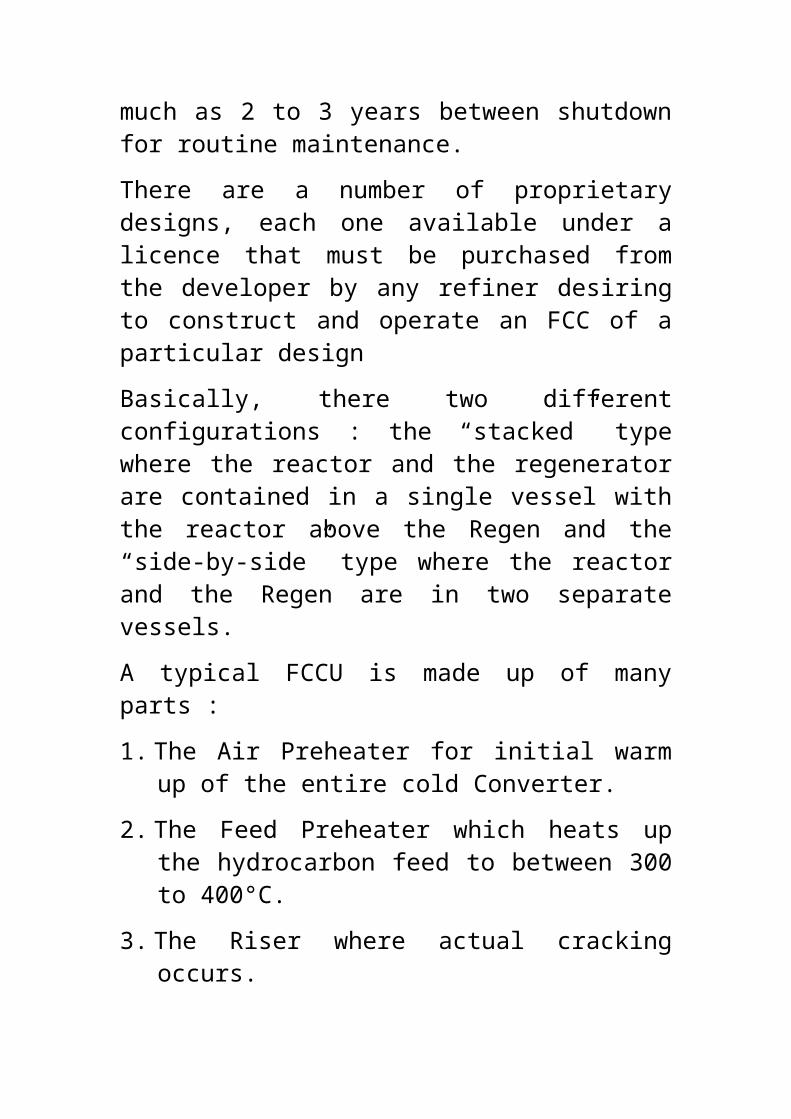
In the filters, the crystallized wax is separated from the oil in the form of a thin cake which is continuously removed from the drum by blowing back with inert gas, usually Nitrogen.
The size of the wax crystals that form as the feed is cooled influences, in an important way, filtration and washing of the crystallized wax.
Washing is with solvent to recover the oil that remains trapped between the wax crystals.
The total quantity of solvent (usually 3 – 5 vols./vol. of oil) added to the charge oil is governed by its viscosity and the filtration temperature. It is best to use the minmum quantity of solvent to reduce operating cost.
The higher the solvent ratio, the lower the charge oil viscosity and the larger the wax crystals. Large crystals result in good filtration rates but the filter cake will be loose with a high pore volume and consequently, a poor washing efficiency. Small crystals generally produce tightly packed cakes with lower filration rates but improved washing efficiency.
The dilution solvent can be a added to the oil feed in different ways and in this way the crystal size of the separating wax can be influenced.
The latest development in this field is the mutiple dilution system, in which the solvent is added to the oil charge in increments before and during chilling.
169

The incremental solvent addition ensures that the bond between the wax crystals is dissolved and thus, no large aggregates are formed. The individual crystals so obtained give an improved filtration rate and owing to the smaller pore volume, the cake will have improved washability characteristics.
It is important that the temperature of the secondary solvent added should be equal to that of the charge mix stream at the point of injection. If the dilution solvent is too cold, “shock chilling” may occur forming fine crystals. Higher temperature partially melts the wax crystals.
The filtrate cake is transferred by conveyors to the wax boots, from where it is pumped to the slack wax recovery section after steam heating.
The filtrate from the outlet of the filters first exchanges heat with the incoming feed mix and then goes to the dewaxed oil recovery system.
In both recovery sections the bulk of the solvent is removed by applying a double-effect evaporation system, additional heat being supplied by hot-oil heaters. From the second (high-pressure) flash column the oil or slack wax is transferred to a steam stripper, where the final traces of solvent are removed.
The solvent recovered from all these sources is returned for further use in the dewaxing process as moist or dry solvent, depending upon the source from which it is recovered.
Any solvent losses are made good by the addition of fresh solvent.170

The quantity of wax removed is typically 20 - 25% weight on waxy feed.
Conditions are adjusted to obtain product oil desired pour point usually -9 to -20oC.
Three grades of Slack waxes are produced in batch operation :
A grade from 100N and 150N waxy Raffinates.
B grade from 250N waxy Raffinates.
C grade from 500N waxy raffinates.
BS slack wax is FCC feed component.
The Table on the next page gives typical feed and product properties:
171

Waxes And Their Properties :
Refined waxes are solid or semi solid materials made up of a mixture of hydrocarbons obtained or derived from petroleum
172

fractions. They are mixture of normal paraffins and iso-paraffins, which may be attached to naphthene rings.
Waxes are grouped into three : Paraffin Waxes, Semi-microcrystalline Waxes and Microcrystalline Waxes.
Paraffin waxes contain a high amount of n-paraffins and are from Spindle and Light Machine oils Slack waxes; semi-microcrystalline ones have lower n-paraffins content but greater amount of iso-paraffins and naphtheno-paraffins and are from heavy distillate oil Slack waxes and microcrystalline waxes contain predominantly iso-paraffins and naphtheno-paraffins and are from de-asphalted oils (DAOs).
Paraffin waxes have molecular weight in the range of 320 to 400, melting or congealing point of 32°C to 73°C and oil content of less than 0.5%. Finished paraffin waxes are odorless and colorless as liquids and as white hard but fragile solids.
The molecular weight of microcrystalline waxes is between 450 to 1000 , congealing point of 60°C to 85°C and oil content of about 3%.. They are yellow or brown and plastic and soft as solids
Maximum oil content is 50% wt for Raw wax (Slack Waxes) and 0.5% to 1.0% wt maximum for commercial waxes.
Uses of Waxes: About 50% of commercial waxes is used in coating and imprenating paper (water-proofing), 10% in the manufacture of candles and the rest in textile, leather, cosmetics, electrical
173

insulation, electrotyping, polish compounding, tyre manufacture, etc.
These many uses of petroleum waxes explain why they are made in different grades to meet the requirements of the different end users.
Wax Production
Solvent MEK/TOLUENE Deoiling Unit (MDOU)Slack waxes produced as by-products of refined lube oils in the MEK Dewaxing Unit (MDU) still contain some oil components as well as undesired low melting point waxes.
The melting/congealing point is always determined because it has direct effect on many characteristics of waxes and their commercial applications. The melting/congealing point is therefore, the main property used for classifying waxes into different grades.
MDOU is designed to produce commercial paraffin waxes by deoiling lube oil slack waxes produced in MDU. The oil product is called Foots Oil and is usually routed to the FCCU feed tank.
In order to obtain waxes with the desired melting point and penetration, it is necessary to remove the oil components and the low melting point waxes; in this way the melting point of the deoiled wax will increase and its penetration will decrease meeting the required specification of commercial waxes.
The process used to remove the undesirable oil components from the slack waxes is called deoiling.
174

The slack waxes are deoiled by using a solvent mixture (MEK and Toluene). The process used to reduce the oil content in slack waxes (deoiling) is very similar to that of dewaxing which has already been discussed under MDU.
The feedstock is deoiled with a solvent mixture (MEK and Toluene). The principle of the process is that the feed is mixed with the solvent and chilled to a certain temperature and the wax which is crystallized at this temperature is separated from the oil by filtration through a rotary vacuum filter.
Everything regarding choice of the solvent is equally valid. In this particular case, use is made of a MEK/Toluene mixture, the composition of which varies from 60/40 (normal) to 70/30.
Methyl Ethyl Ketone is the agent which precipitates the waxes, i.e. given that waxes are barely soluble in it, as the temperature falls they separate in the form of crystals of a size suitable for the subsequent filtration. However, as its solvency versus oil is also limited, a large quantity of oil would also separate with the waxes.
The purpose of using toluene with the MEK is to keep the oil in solution, at the same time reducing its viscosity at low temperatures to aid separation during filtration. Toluene on its own would tend to dissolve even large quantities of waxes, but the presence of MEK prevents this.
The purpose of washing the wax cake is to remove the oil and the soft wax that remain blocked between the wax crystals; it is thus obvious that large crystals withhold large quantities of unwanted
175

compounds which worsen the properties of the finished wax (e.g. the melting point falls and penetration increases).
In the multiple dilution system, the solvent is added to the feed in incremental amounts before and during chilling.
For a particular slack wax feed the filtration temperature governs the melting point, penetration and yield of deoiled wax. When the filtration temperature is increased, the wax melting point is increased, the penetration is reduced and the wax yield is reduced. The opposite is the case when filtration temperature is decreased.
The Feed and product Hard Wax properties are shown in the Table in the below.
Wax Hydrofinishing Unit ( WHU )
176
GRADES
PROPERTIES A B C
Slack Wax
Hard Wax
Slack Wax
Hard Wax
Slack Wax
Hard Wax
Flash Point (°C) 195 195 220 220 225 225
Congealing Point (°C)
48 48 – 54 54 59 -62 60 66 – 70
Max. Oil Content (%weight)
15 0.5 20 0.5 25 1.0

The purpose of WHU is to produce food grade waxes by complying with some health regulations and is the final step in the manufacture of commercial waxes.
As earlier discussed, wax consists of redominantly n-paraffins ( above 70% ), the rest being mainly iso-paraffins and some aromatics, polyaromatics and organic compounds of sulfur, nitrogen and oxygen. The carbon chain length is usually 20 to 36, melting point ranges from 400c to 700c and sulfur content is usually between 0.01 and 0.5 %wt.
Hydrofinishing is a catalytic hydrogenation treatment of de-oiled waxes ( hard waxes ) in order to improve their color, color and oxidation stability, to reduce impurities ( O2, N2 and S compounds ) and to convert aromatics to naphthenes to meet FDA specifications .
The food and drug administration ( FDA ) test concerns the aromatic content in waxes and this must be lower than a specified value to pass the FDA test. This is because the product waxes are expected to be of food grade and the aromatics are carcinogenic.
The reaction occurs in a fixed bed reactor packed with a catalyst containing Nickel and Tungsten ( Wolfram, W ) on alumina support base at temperature range of 2500C to 4000C and pressure of 50 to 100 kg / cm2.
The main reaction is the de-aromatisation of the aromatics and polyaromatics to naphthenes and naphthenes fused with aromatics.
Break down of organo sulfur, nitrogen and oxygen compounds also occurs to produce H2S, ammonia and water with a small amount of
177

hydrocarbons with lower molecular weights and lower boiling points than the parent organic compounds.
Hydrocracking and isomerisation are also possible but because they produce some oils which will affect the properties of the wax ( oil content and melting point ), conditions are held such that these side reactions are substantially minimsed.
The Table below gives the key properties of the hydrofinished waxes.
PROPERTIES GRADES
A B C
1. CONGEALING/ MELTING PT 0C 54 - 58 59 – 60 66 – 71
2. SULFUR %WT - - -
3. MAX. OIL CONTENT %WT 0.5 0.5 1.0
4. COLOR WHITE WHITE WHITE
5. FDA TEST PASSED PASSED PASSED
178

ASPHALT BLOWING UNIT (ABU)
Asphalt is an amorphous dark brown to black, odorous, cement-like, combustible mixture of fused polynuclear aromatics with cross-linkages made of methylene, ether and thioether bonds.
It is usually obtained from petroleum processes and is insoluble in most pure hydrocarbons. Crude oil composition is vital in refining for asphalt beccause asphalt yields are practically set by crude oil composition while asphalt quality is subject to processing. API gravity and Carbon Residue can give a rough index of the quantity of asphalt present in crude oil.
Raw asphalt has poor characteristic : high penetration, very low softening point and other qualities.
Asphalt together with Resins (materials of similar composition but of linear polymers and hydrocarbons soluble) make up 5 – 15% of Crude Oil.
The oil fraction in asphalt is a mixture of oils similar to very heavy lube oils. Resins are solids and semi solids.
The solid fraction is called Asphaltene which is responsible for the consistency of asphalt: the more the asphaltene content the higher the viscosity and softening point but the lower the penetrattion.
Hence properties of asphalt vary over a wide range depending on the properties and the nature of the various constituents.
179

Sources of Raw Asphalt:
• Distillation: HVDU.• Air Blowing: ABU.• Precipitation or Solvent Extraction: PDU.
Distillation and Precipitation remove relatively fluid oils and waxes without chemical conversion
Asphalt Product Types:
• Solid grade : 80/100 Penetration. 60/70 Penetration.
50/60 Penetration.
• Liquid (Cut back) grade: Medium curing (MC). Rapid curing (RC).
Solid grades are usually produced by air blowing although 80/100 grade can also be produced by direct blend of PAS and Vacuum Residue - 2.
Liquid or Cut back grade is produced by blending a petroleum solvent with asphalt:
Volatile solvent like naphtha gives Rapid Curing (RC) grade which hardens very quickly due to the solvent which evaporates easily.
Medium Curing (MC) grade uses less volatile solvent like kerosene to blend and hence hardens less quickly.
RC and MC grade is each divided into 6 sub grades numbered 0, 1, 2, 3, 4 and 5 depending on the amount of solvent used in blending.
180

The 0 sub grade has the greatest amount of solvent and is most fluid, the 5 sub grade has the least amount.
The same sub grade in each class has the same fluidity i.e. RCO and MCO have the same fluidity but differ only in the length of time required for the solvent to evaporate.
Solid Grade Product Quality:
Softening Point is determined using Ring and Ball tester and is the temperature at which the ball placed on a ring of heated asphalt falls through the ring and it varies from 45oC for 80/100 to 58oC for 50/60 grade.
Penetration is a measure of hardness and is the distance a needle under a standard load will penetrate the asphalt in 5 seconds at a specified temperature, usually 77oF (25oC), measured in 1/10mm unit. The expression “50/60 Pen asphalt” refers to an asphalt with a hardness of between 50 and 60.
Flash Point varies from 225oC for 80/100 to greater 250oC for 50/60.
Fundamentals of ABU
The unit comprises of four (4) Sections:
the Oxidizer,
the Hot Oil System,
Oil Scrubbing System (to recover cracked oil) and
Fume Incinerator to burn foul smelling spent gases.
181

Air blowing is an oxidation reaction carried out in the oxidizer column. The main reaction is dehydrogenation by the oxygen in the blowing air and generation of water from reaction with hydrogen from the dehydrogenated hydrocarbon in a Condensation polymerization reaction.
Air blowing increases the asphaltene content at the expense of resins and oils leading to higher softening point and lower penetration.
The reaction is exothermic and temperature rises as the air rate increases. Temperature control is therefore vital and usually kept at 300oC maximum.
Product properties depend on reaction temperature, air rate and feed characteristics. Hence operation is carried out at appropriate conditions to produce products with desired properties.
Flow through the oxidizer is counter current: Asphalt from the top and air blowing from the bottom.
Asphalt product stream is withdrawn from the bottom and cracked oil vapour and gases from the top. The oil is scrubbed to recover it as FCCU feed. The scrubbed overhead vapour is burnt in the Incinerator.
Asphalt Blending :
Only Cutbacks and 80/100 grade are blended.
In-line blending is carried out based on laboratory bench result to determine components ratio and regular tests for softening point, penetration and flash point are carried out as control measures.
182

183

LUBES PLANT PROCESS SCHEME
184
1A 1B 2 3 4
1C
CRUDE OIL
SURPLUS DISTILLATES
PROPANE DEASPHALTING ASPHALT EXTRACT SLACK
WAX
CRACKER
FEED
WAX A
FUEL OIL BLEND
FINISHED BASE OILS
CRUDE UNIT VACUUM UNITSOLVENT
EXTRACTION DEWAXING FINNISHING
M
D
O
U
W
H
U
WAX B
WAX C
1A 1B 2 3 4
1C
CRUDE OIL
SURPLUS DISTILLATES
PROPANE DEASPHALTING ASPHALT EXTRACT SLACK
WAX
CRACKER
FEED
WAX A
FUEL OIL BLEND
FINISHED BASE OILS
CRUDE UNIT VACUUM UNITSOLVENT
EXTRACTION DEWAXING FINNISHING
M
D
O
U
W
H
U
WAX B
WAX C
LONG
RESID

STAGE 1A, B, C: FEED STOCK MANUFACTURE
STAGE 2: VISCOSITY – TEMPERATURE (VI) CHARACTERISTICS AND COLOR IMPROVEMENT
STAGE 3: POUR POINT IMPROVEMENT
STAGE4: STABILITY IMPROV EMENT, BLENDING, PACKAGING AND SHIPPING.
185

SCHEMATIC PROCESS FLOW DIAGRAM OF LUBESPLANT
Asphalt
Base Oils
Waxes
PropaneDe-asphalting
VDU-2
Asphalt Blowing
MEK-Deoiling
WAXHydro-
Treating
FUELSPLANT
CDU-2
Naphtha
Kero
Gas oil
ATM Residue-2
Sh
ort
Re
sid
ue-2
Waxy Distillates
100N150N150N500NBright Stock
GRADES A,B & C
GRADES50/6060/7080/100

187

KRPC receives both local and foreign crude from Warri through a 606 km pipeline.
188

Four crude tanks each are available for Local and Foreign crude oils. Each set of crude tanks has a capacity of 327,600 barrels or 6.5 days feedstock for Fuels Plant at 60,000 Barrels Per Stream Day(BPSD).
A total of 166 tanks are available to handle crude, intermediate and finished products.
Product evacuation is by Road, Rail and Pipeline and there is
capacity to load 192 trucks of 33,000 litres each daily.
189

190

Distillation Columns:Vacuum distillationAtmospheric distillationPressure Distillation
191

192

TANKAGE
TANK TYPES
Low Pressure : Cone Roof
High Pressure: Floating Roof
Spheres
Spheroids
Hemispheroids
Gas Holder
Safety: Flame Arrestor/Breather Valve
193

FEATURES ASSOCIATED WITH VESSELS OPERATION
Sizing or Capacity (how long and for what service?)Is it hot or very cold service (temperature sensitive)
lagging required?
It must have nozzles for inlet and outlet plus side streams and sensorsIt must breathe – very important for self protection (over pressure and under pressure can both be experienced)It must be accessibleIt must be supportedLabelsDrains and Utility Connections
AS OPERATOR YOU MUST:
Know the service of the vessels you operate – what does it handle.Understand the conditions inside each vessel.Know the accessories and the linkages.Understand the location – does it pose any threats? Is it near heaters?Are associated auxiliaries well Located? Can they be seen and serviced.Where the vessel drains to.
194

How much material the vessel holds.How to prepare the vessel for entry.
Grasp the associated risks with the vessel
195

PETROLEUM PRODUCTS AND THEIR USES
Category :
Petroleum products are usually grouped into three categories :
Light Distillates : LPG, Naphthas and Gasoline
Middle Distillates : Kerosine, Aircraft Jet Fuel and Diesel Oil
Heavy Distillates and Residium : Fuel Oil, Lubricating Oil, Waxes, Asphalt, Tar and coke
Liquefied Petroleum Gas (LPG)
LPG, which consists principally of propane and butane, is produced for use as fuel (cooking gas).
LPG is also an intermediate material for the production of light olefins used in the manufacture of Petrochemicals.
Premium Motor Spirit (PMS)/Petrol/Gasoline
Motor gasoline is the most important refinery product. It is a blend of hydrocarbons with boiling ranges up to about 204OC. The important qualities for gasoline are octane number (antiknock), volatility (starting and vapor lock), and vapor pressure (storage and environmental control).
196

Kerosene (Aviation, ATK and Domestic, HHK)
Straight Run Kerosene is used for cooking, lighting, heating (Domestic) or as Aviation jet fuel (ATK) after further processing in KHU. It is also used as solvent.
o Automotive Gas Oil (AGO)/Diesel
Used as diesel engine fuels and domestic heating oils.
Fuel Oils (LPFO and HPFO)
To power many marine vessels and Power Plants. Commercial buildings and industrial facilities use a blend of residual and diesel fuels (LPFO) for heating and processing.
Asphalt ( Cured and Solid Grades)
Asphalt is used for road pavement and as roofing materials because it is inert to most chemicals and weather conditions.
Lubricants ( Oils and Greases )
Special refining processes produce lubricating oil base stocks. Additives, such as demulsifiers, antioxidants, pour point depressant and viscosity improvers, thickners, etc are blended into the base stocks to provide the characteristics required for motor engine oils, industrial greases and other lubricants.
197

THE CHALLENGES
The major challenges being faced by the refining industry are from the environmentalist in terms of :
Reduction in air pollution by reducing :
Carbon oxides emissions
Nitrogen oxides emissions
Sulfur oxides emissions.
Particulates emissions
Reduction in industrial noise pollution
Water pollution and sludge/solid Wastes disposal.
Techonology is moving faster in the area of air pollution much more than the others increasing initial capital and mainteance costs as a result of refiners having to install additional pieces of equipment needed to comply with pertinent environmental restrictions as laid down by government Environmental Protection Regulatory Agencies.
Another important challenge is in the inadequacy of technical personnel, especially experienced operators and process engineers, resulting from aging work force and recruitment not matching the spate of retirementand other forms of staff attrition.
198

We also have the serious situation of responsibilty given to the operational SBUs and CSUs not being matched by adequate financial authority because these entities are not yet being run as commercial enterprises.
199

PETROCHEMICALS PROCESSES
200

CONTENT
INTRODUCTION
SOURCES OF RAW MATERIALS
EQUIPMENT
COMMON REACTIONS
PETROCHEMICALS PROCESSES
ANIONIC SURFACTANTS : DETERGENT ALKYLATES
LINEAR ALKYLBENZENES ( LAB ) PROCESS SCHEMES
CARBON BLACK PROCESS SCHEME
POLYMERISATION
POLYMERS
ALKENE MONOMER PRODUCTION
POLYETHENE PROCESS SCHEME
POLYPROPENE PROCESS SCHEME
USES OF POLYMERS
201

INTRODUCTION
The Petrochemicals industry is commonly called ‘molecular architecture’.
This because finished products are built up of basic building blocks e.g. CH3-, C2H5-, C3H7-, -COOH, -OH, -NH2, -CONH2, -SO3H, -O.SO3H, - O -, - S-S -, etc.
Petrochemicals processes convert refinery products /byproducts into intermediate or finished consumer products – several thousands of them.
Process plants are similar to those found in refining Plants. Hence Refining and Petrochemicals Plants are usually located next to each other and integrated into one huge complex.
The major difference is in product purity which is more important in Petrochemicals Plants and to achieve this, equipment are usually smaller, e.g. distillation columns are usually taller (more trays) but thinner (process less volume).
SOURCES OF RAW MATERIALS
1. Primary Raw Materials :
Natural Gas :
Mixture of CH4 (Methane) with small amounts of higher alkanes ( Ethane, Propane, C4 and C5 HCs), CO2, N2 and S compounds, H2O and water vapour.
It can be Associated – “Wet”, containing comparatively large amounts of easily liquefied HCs.
202

Or Non – associated “Dry”, although may have appreciable amounts of C2 and higher alkanes
Where it is virtually CH4 (methane) the range of uses is limited.
Where it contains higher paraffins, it is used as major source of lower alkenes (Olefins) – NGL.
Refinery Gases – FCC LPG which is high in olefinic content : 65-70% Propene and 55-60% Butenes.
Refinery Liquid Hydrocarbon Fractions : Naphtha, Kerosene, Reformate for BTX and Ethylbenzene extraction and Decanted oil ( Carbon Black ).
Secondary Raw Materials:
Ethane and higher Paraffins.
Ethene, Propene, Butenes and higher olefins.
EQUIPMENT
Typical Refinery pieces of equipment are also found in the Pertochemicals Plant.
Other equipment found in the Petrochemicals Industry are Crytallizers, Filters, Settling Tanks, Cyclones, Leaching Plants and Evaporators.
Reactors :
Batch Stirred Tank Reactor (BSTR).
Continuous Stirred Tank Reactor (CSTR).
Tubular Reactor and Fixed Bed Reactors.
203
COMMON REACTIONS
Hydrogenation: Benzene to Cyclohexane.
Dehydrogenation: Isopropanol to Acetone and Hydrogen.
Oxidation: Ethanol oxidised to acetaldehyde and water.
Ethene oxidised to Ethylene Oxide.
Reduction: Acetaldehyde is reduced to Ethanol with H2
Halogenation: reaction involving F, Cl, Br and I.
Chlorination: CH4 + Cl2 à CCl4 + HCl.
C2H4 + Cl2 à ClCH2 – CH2Cl.
Alkylation: Benzene + C8H18 (octane) à Octyl Benzene.
Isobutane and Propylene give isoheptane.
Benzene reacts with Ethene to yield Ethylbenzene.
De-alkylation: Toluene to Benzene or Benzene reacting with Xylene to give two molecules of Toluene.
Esterification: Ethanol + Acetic Acid give Ethyl Acetate ( the Ester ) and water.
204

Hydrolysis: EthylAcetate + H2O give Acetic and Ethanol. This is the reverse of Esterification.
Sulfonation (Sulphuric Acid + Sulfur trioxide).
Benzene + H2SO4/SO3 give Benzene Sulfonic Acid (R-SO2 – OH).
Sulfation : To produce Sulfate Ester with Aq. Sulfuric Acid)
Octene-1 + H2SO4 give Octyl, 2-Sulfuric Acid Ester (R-O-SO2-OH). R = Octyl radical.
Condensation: Two molecules reacting to give a more complex one and eliminating a smaller molecule (e.g. water).
2 moles of Acetone give Mesityloxide and water.
Polymerization:
Polymerisation is the most important reaction in the Petrochemical Industry. It is used in the manufacture of many consumer items called Polymers.
The word Polymer is derived from two Greek words : Poly – Many and Meros – Parts / Segments.
Polymers are high molecular weight materials, consisting of long chains of repeating single molecules or slight modification of them called Monomers.
A monomer can be mono functional (Olefins) or bifunctional (Amino acids) even trifunctional.
205

Polymerization is usually a catalysed reaction which can be:
Addition: one monomer adding to each other or one another (Olefins – Homopolymers / Copolymers / Terpolymer).
Condensation: monomer molecules combining together with the elimination of small molecules e.g. water.
• Homopolymer Condensation Polymerization: Amino acid to give Polyamide.
• Copolymer Condensation Polymerization: Ethylene glycol reacting with terephthalic acid give Terylene or PTF or a diamine reacting with a dicarboxylic acid producing Nylon material.
• Polymerisation can occur via Free Radical reaction or Ionic ( carbocation or carbanion )reaction. The reaction occcurs in three steps for either mechanism : Initiation. Propagation and Termination.
206

SOME PETROCHEMICALS PROCESS SCHEMES
SURFACE ACTIVE MATERIALS ( SURFACTANTS }
Anionic surfactants are the most important synthetic surfactant making up 60 – 70% of total production of synthetic detergents
Usually used as sodium salt of the organic sulfonic acids or less frequently sulphuric acid esters.
They are superior to soaps in that they form relatively soluble Ca and Mg salts and are completely ionized under all conditions of acidity.
They are ultimately derived from petroleum in most cases and are also cheaper than soaps in many applications.
The most important anionic surfactants are Alkylbenzene sulphonates manufactured by a straight forward Friedel-Crafts reaction between straight chain alkenes and benzene in the presence of an acid catalyst to produce alkylbenzenes which are then sulphonated with a 4% SO3-air mixture at 40 – 50oC.
Straight chain alkenes yield largely biodegradable products.
If a solid detergent is required the sulphonic acid is neutralized with caustic soda, NaOH, the resulting slurry mixed with builders, spray-dried to a smooth-flowing powder to which heat sensitive ingredents such as bleaches and enzymes may be added.
207

For liquid formulations, neutralization is effected with caustic potash, KOH or alkanolamines.
LINEAR ALKYL BENZENE PRODUCTION
Process Scheme : Five Units involved are :
Kerosene Hydrodesulfurisation Unit (HDS) : For Molex Feed Production.
The Molex Unit : Produces Normal Alkane.
The Pacol Unit : Produces Normal Alkene.
Benzene Production And Thermal Hydro-dealkylation Unit (THDA) – For Benzene Optimisation .
The HF Alkylation Unit.
HDS
The feed to this unit is raw kerosene from the Refinery Crude Units -1 and -2 but by design CDU- 2.
Its purpose is to remove S and N contaminants to avoid poisoning the Molex unit molecular sieves and Pacol unit catalyst.
The process is similar to NHU but operate at higher pressure.
The raw kero is pre-fractionated to eventually produce a four-carbon cut ( C10 – C13 for light LAB or C11 – C14 for heavy LAB ) which actually is what is desulfurised after preheat in the reactor and then
208

fed as Treated Kero to the Molex Unit after product stripping to remove light ends.
MOLEX UNIT
A UOP licensed process separates normal paraffins from isoparaffins and others using proprietary zeolite molecular sieves which adsorbs C10 – C14
(decane through tetradecane) fractions which are then desorbed using a low boiling hydrocarbon.
Products are Kero solvent raffinate, Isoparaffins and normal paraffins ( nC10 to nC13 for light LAB and nC11 to nC14 for heavy LAB ) as a ready stated.
PACOL UNIT
This is another UOP licensed process that converts linear or normal paraffins from the Molex Unit to linear Olefins using platinum on alumina support base as the catalyst.
The linear Olefins thus produced, altogether forms, one of the two feedstocks to the HF Alkylation Unit.
THDA UNIT
THDA produces benzene (the second feed) for HF Alkylation unit.
The feed to this unit is the Reformate from the Refinery CRU. The reformate is first stripped, to remove as the overhead product, benzene and C4 and lighter HCs as fuel gas.
The middle cut is Toluene, Xylenes, Ethylbenzene and little benzene.
209

The bottom product contains mostly C9+ with little C8
materials and is returned to refinery gasoline pool.
The C6 and C8 middle cut is then subjected to controlled hydrothermal cracking (hence the name , THDA ) resulting in increased yield of benzene from a given quantity of reformate after product stripping plus byproduct, Toluene concentrate.
HF ALKYLATION UNIT
The linear Olefins from Pacol Unit are reacted with benzene in the presence of Hydrofluoric (HF) acid as the catalyst.
The main product is Linear Alkyl Benzenes which are purified, freed from residual acid by neutralisation and then sold to end users ( detergent manufacturers ).
Byproduct is Heavy Alkylates which after being freed from acid also by neutralisation and purified are also sold to end users for the manufacture of transformer oil, ATF, etc.
210

211
212

213

CARBON BLACK PRODUCTION ( CB )
CB is poduced mainly by controlled incomplete combustion/thermal decomposition of the FCCU Decanted or Conversion oil or gases. Yield is high and control over CB properties (particle size and structure) is wide.
CB comprises fine elemental carbon particles: 90 – 99% carbon.
Process Scheme
The Reactor feed is filtered in a high voltage separator to remove entrained FCCU catalyst, coke and metals.
Filtered feed goes to the Reactor where controlled burning in pre-heated air and fuel gas (mainly C3) provide the heat necessary to crack DCO at about 1,000 – 1,200oC.
The residence time in reactor is controlled through quenching with steam or water.
Potassium nitrate ( KNO3 ) solution is also injected in controlled amounts to regulate carbon black particle size.
KNO3 additive injection, control of residence time in the reactor and control of temperature affect the specific surface area and structure of the various grades of CB produced.
The reactor effluent, comprising colloidal carbon black particles suspended in the off-gas stream, is
214

used to pre-heat the feed and then cooled in quench sprays.
The cooled CB is filtered in special fibreglass filter bags, pulverised and discharged into a surge tank after which it is pelletized into the desired spherical shape and dried to moisture level of less than 1%.
The dried CB is conveyed in a bucket and screw conveyors through a magnetic separator to remove metals before being sent to storage silos for bagging.
The capacity of the Plant is 104.51MT/DAY of Decant Oil and product yield is :
S/N PRODUCT QUANTITY
( MT/D )
YIELD
(%WT)
1 OFF GAS 50.01 47.85
2 HARD CARBON BLACK 54.50 52.15
3 TOTAL 104.51 100.00
215

Two main types of CB are produced:
TYPES GRADES
High Abrasion Furnance (HAF) N326, N330 and N375
Intermediate Super Abrasion Furnance (ISAF)
N220.
TYPICAL FLOW SCHEME OF A CARBON BLACK PLANT
216

SOME USES OF CARBON BLACK :
o Coloring agent for Ink and Paints
o Black pigment for inkjet ink and toners
o Resins and Film coloring agents: because of its high tinting strength, thermal stability and excellent high UV absorbing capacity, it is used with resins for the manufacture of car bumpers, wire coverings ( insullation ) and steel pipe linings.
o Electric Conductive Agent : CB has graphite type structure and hence has
217

high electric conductivity. Hence its use as conductive filler in plastics, elastomers, paints, films, adhesives and pastes.
And in fuel tank caps and pipes in cars to prevent generation of static electricity as an excellent –antistactic agent.
o Electronic Equipment Related Materials : due to its stable resistance it is used in display components and magnetic recording materials.
o It has reinforcing capability and hence imparts a high tensile strength and abrasion resistance to rubbers, therefore its use in tyre, fan belt and conveyor belt manufacture.
POLYMERISATION AND POLYMERS
A Polymer ( Greek : polymeros – many parts or segments ) is high molecular weight (between a few thousand and a few hundred thousand,say 10,000 – 200,000) material, consisting of long chains of repeating single molecules or slight modification of them called Monomers.
Classification
There are two ways of classifying Polymers
1. Based On The Source :
218

Natural – e.g. Proteins ( wool, silk, leader, muscle fibers, enzymes, nucleic acids ), Polysaccharides ( starch, cellulose [ cotton, wood, paper, hemp, sisal ,linen ] and Rubber.
Synthetic – e.g. Polyethylene, Terylene, Perspex, Nylon etc.
About 80% of world organic chemical industry is used in the production of synthetic polymers.
Synthetic polymers are as diverse as the natural ones. We put on polyester clothes, sit on PVC chairs, write on formica table top, work on formica kitchen table top, our carpets and rugs are polymer materials, paint our walls with latex paints and wooden floors with polyurethane. Our cars have man made rubber tyres and vinyl upholstery. Our dishes may be melamine. Others are food and bread wrappers, shopping bags, teflon coated frying pans, tooth brushes, hair brushes, electrical insulators, plastic jugs, plates, cups, buckets. Bowls, cutlery and heart valves, aircraft windshieds, etc.
Therefore synthetic polymers (plastics, elastomers and fibers) are the products of the chemical industry with which the man in the street is most familiar and which have had the greatest impact on his life.
2. Based On Structural Make Up :
Polymers are classified as Elastomers, Plastics and Fibers depending on their initial moduli of elasticity:
219

Elastomers ( with elastic properties ): 15 – 150 psi; e.g. Natural rubber, polychloroprene, polyisobutene and polybutadiene, etc.
Plastics ( thin sheets, hard and mouldable solids, coating, adhesives ): 1,500 – 15,000 psi; e.g. PVC, PVA and polystyrene, etc.
Fibers ( thread-like ): 150,000 – 1,500,000 psi; e.g. silk, cellulose, polyamides and terylene, rayon, etc.
Polymer properties of high viscosity, tensile and impact strength and toughness depend on molecular weight and chain length.
Mechanical strength develops from chain length of about 50 monomers and increases up to a chain length of 500 units after which not much difference is observed.
Synthetic polymers are usually named after the monomer / monomers with the prefix ; poly e.g. polyethylene, polyvinyl chloride, polyvinylidene chloride, polymethylmethacrylate, ABS ( poly acrylonitrilebutadienestyrene ), etc.
PLASTICS
There are two major types: Thermoplastics and
Thermosets.
Thermoplastics : When heated melt to liquid which on cooling forms a solid with no change in any of its properties and these processes can be repeated over and over again.
220

Action of heat only makes the solid plastic and pliable e.g. Polyethylene, Polyvinylchloride, Polypropylene, Polystyrene etc.
Thermosetting Plastics : Set by the action of heat, that is, once the polymer is heated, formed into a shape and cooled down, no amount of heating will cause the polymer to melt the second time.
Rather it will decompose or burn with increasing temperature.
These is due to cross linkages in their structures e.g. Bakelite: a Phenol -Formaldehyde polymer.
PLASTICS : POLYOLEFINS (POLYETHYLENE – PE; POLYPROPYLENE - PP)
Feed Stocks can be produced by :
Cracking of light alkanes e.g. NGL to produce mainly Ethylene and Propylene.
Cracking of Naphtha.
Cracking of Residual Oils ( Hydrocracking, Visbreaking and Coking).
221
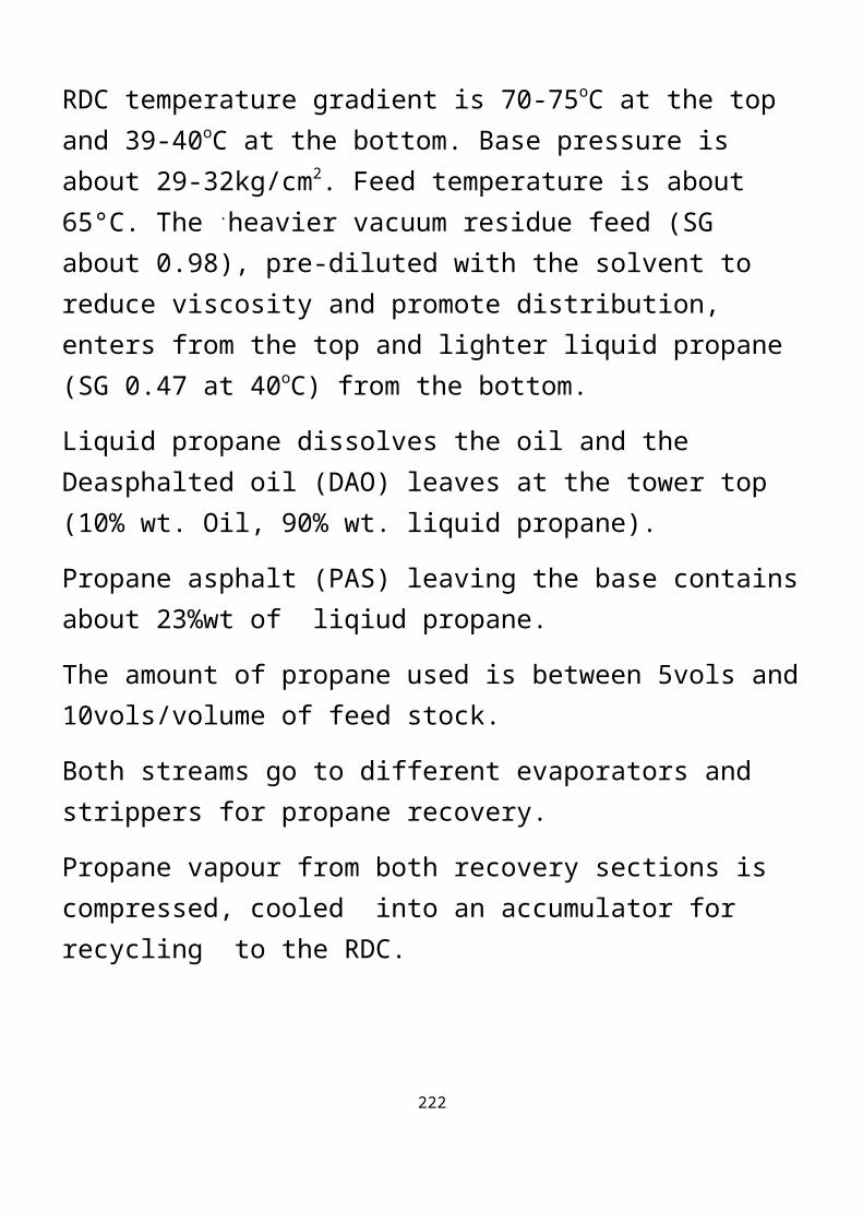
Stripping of FCCU LPG which is rich in Propene and Butenes ( see Sourcces Of Raw Materials above ).
THE OLEFINS PLANT
The diagram below is a Process Flow Diagram of a typical Olefins Plant where the feed NGL ( 89,900MTPA ) is steam reformed ( cracked ) and 98,000MTPA of Propylene Rich Feed ( PRF ) later added to the cracked materials to produce polymer grades of ethene ( 260,000MTPA ) and propene ( 126,000MTPA ) as the main products.
NGL at a pressure of about 36kg/sq.cm. and a temperaure of 34°C is first prefractionated in a column from which Virgin C₅+ is taken at the bottom and C₂ - C₄ alkanes are removed from the overhead.
These are then preheated and mixed with dilution steam and DMDS to reduce coking before being routed to the Pyrolysis furnaces; first through the Convection section where the mixture is heated to 624°C and then distributed into 192 radiant tubes for cracking at about 1000°C and very short residence time ( milliseconds ) to produce olefin-rich gas or vapor.
If there are six furnaces, five are usually in cracking mode and the sixth on decoke after about 12 days in operation and then kept on standby to be put back into service as soon as one other furnace is ready for decoking.
222

The cracked vapor from the operating furnaces are rapidly cooled by being used to generate ultra high pressure steam at about 105kg/cm2 in a series of quench heat exhangers to reduce secondary cracking reactions which can reduce ethylene and propylene yields.
In fact three levels of steam is generated in this Plant :
Ultra High Pressure Steam at 105kg/sqcm and 505°C.
High Pressure Steam at 46kg/sqcm and 400°C and
Low Pressure Dilution Steam at 8kg/sqcm and 192°C.
The vapors ex these exchangers are fed into a Water scrubber to wash and further cool the vapors. The HC ladden quench water is cooled to around 80°C before being sent to a separator where Quench water, process condensates, light and heavy oils are separated. The oils are pumped to the Offsite for burning.
The gas or vapor exiting the top of the Scrubber is compressed in five stages from 0.32kg/cm2 and 38° C with interstage cooling and water draining from the interstage knock out drums to 40kg/sq.cm.
The vapors are subjected to caustic wash after the fourth stage to remove Acid Gases ( mainly hydrogen sulfide and carbon dioxide ).
223

The 5th stage discharge is then combined with a Propylene –rich feed ( PRF ), cooled to about 13°C and sent to a separator from the top of which the Process gas goes to the Gas dryer packed with molecular sieves and then a filtered to remove water to less than 1ppm. The Process liquid from the separator is sent to a coalescer and then to a liquid dryer before joining the gas stream for a series of cooling and chilling to -120°C prior to entering the De-methaniser. Here , the overhead methane is sent to Fuel Gas and the 85% pure hydrogen sent to a Hydrogen Purification unit to yield 99.5% pure hydrogen for hydrogenation in the Converters.
The bottom of the De-methaniser is fed to the De-ethaniser. The top product is C2 material, containing ethene and acetylene, is routed to the Acetylene Converter where the acetylene content is mildly catalytically hydrogenated to ethene, ethane and Green oil. The green oil is removed in the Green Oil Absorber and the C2- / C2= mixture goes to the C2
Splitter ( 75m high ) from where the top ethene product is sent to storage tank or as direct feed to the Polyethylene Plant . The bottom ethane product is recycled to the furnaces for cracking.
The De-ethaniser bottom is sent to the De-propaniser to remove propene/propane mixture from the top. This mixture is sent to the Methylacetylene/Propadiene ( MAPD ) Converter where these compounds are mildly catalytically
224

hydrogenated to propene and propane. The Converter effluent is then sent to the C3 Splitter ( a 2-in-1, 70m high fractionator with180 trays ) which separates propene as the top product which is sent to tank and the bottom propane is also recycled to the furnaces for cracking.
The bottom of the De-propaniser goes to the De-butaniser to remove C4 material as the top product which is sent to the C4 Hydrogenation Reactor to convert Butenes/Butadiene to Butane which is recycled to the furnaces for cracking.
The De-butaniser bottom is heated, filtered and de-watered before being sent to a coalescer and then to a C5 Hydrogenation Reactor to produce Craked C5+ as the main product.
225

226
OLEFINS PLANT BLOCK FLOW DIAGRAM

POLYETHYLENE ( PE ) PROCESS SCHEME
The process description applies to EPCL PE Plant with a capacity of 270,000MTPA of Polyethylene and 22,000MTPA of but-1-ene.
The feed is ethene / hydrogen mixture with cyclohexane as a carrier solvent .
The Plant is divided into Areas :
1. Synthesis Area – The Reactors, etc.
2. Finishing Area – Extrusion, Pelletisation, etc.
3. Solvent Recovery Area.
Ethylene from tank and or from the Olefins Plant is admitted into a surge drum after which it is compreessed to 43kg/sq.cm., cooled and sent to a purifier/dryer to remove water and other impurities. The dried and cooled gaseous monomer is combined with dried liquid mixture of cyclohexane and but-1-ene forming a liquid-gas mixture which is also cooled before being sent to an Absorber with a packed internals where ethene and cyclohexane are absorbed in an exothermic process requiring heat removal. The combined feed is pumped to 34kg/sqcm then to 170kg/sqcm before being cooled to the Reactor inlet temperature of slightly over 100°C.
Three Ractors are used depending on the polymer grade to be produced :
227

Stirred Autoclave Reactor called Reactor #1.
Trimmer Reactor ( similar to the Tubular reactor ) called Reactor #2.
Pipe or Tubular Reactor called Reactor #3.
The reaction is fast at about 290°C and 170kg/sqcm and ethylene conversion of upto 95% is achieve and most of the co-monomer is also converted.
Hydrogen is added at a pressure depending on the grade to control the grade and act as chain terminator.
Catalyst used is Ziegler-Natta type, mainly Titanium tetrachloride blended with co-catalysts ; triethylalumnium, diethylaluminium chloride and tetraisobutyl-aluminoxane.
The grade of PE to be produced determines the relative amout of catalyst and co-catalysts to be used.
Catalyst and co-catalyst are ususally injected to Reactor #1 and de-activators, Pelargonic acid and Acetylacetone added after reactor #2 to help terminate the reaction and make for easy separation of unused catalyst system from the polymer in an Absober that absorbs the catalyst system.
Product separation occurs in two stages at the Intermediate Pressure Separator ( IPS ) and Low Pressure Separator ( LPS ) where most of the solvent carrier, cyclohexane and other vapors are flashed off.
The polymer exiting the LPS is fed to the Extruder where additives are added. The extruder pushes the polymer
228

to a Die Plate with 180 holes. A Pelletiser with 18 knives cut the polymer into small pellets as it emerges from the Die plate. A water current transports the pellets to the Delumper to remove over size pellets/resins then to a Stripper to remove residual cyclohexane which is routed to the Recovery area.
The resins are then conveyed to Spin dryers where the resins are separated from water using a stream of hot air.
The dried product is sent to Hold-up Bins, then to the Blenders and finally to product Silos ready for bagging and packaging.
229

230

POLYPROPYLENE ( PP ) PROCESS SCHEME
The capacity of the PP Plant is 80,000MTPA and it is easily expandable to 120,000MTPA. The plant can also produce co-polymer with ethylene.
The key points are :
The reaction is in liquid phase in tubular Reactors.
The process is continuous with short residence time in the reactors.
The catalyst is ( Ziegler-Natta ) Titanium tetrachloride supported in Magnesium chloride for stereo-specificity.
Co-catalysts used are Triethyl aluminium and cyclohexane dimethyl silane.
An anti-foulant is added downstream of the reactors to reduce the tendency of liquid polymer fouling the reactor by sticking on their hot walls.
Hydrogen is added to the system as a chain terminator and as such determines the molecular weight distribution and the strength of the polymer.
The feed to the plant propylene from the outside battery limit ( OSBL ) at about 95% purity. It is further purified to around 99% purity within the Plant. The impurities removed are mainly carbon monoxide, mercaptans and moisture.
231

Catalyst combination determines the stereo-regularity of the finished product.
There are three kinds of PP which are characterised by the regularity of the Methyl groups along the hydrocarbon chain.
PP product is steroeregular, that is, the methyl groups are oriented to the backbone of the molecule in a regular way:
In the Isotactic form they all lie on one side of the chain.
In the syndiotactic form they are on alternate sides.
Stereoregular polymers pack together more easily than non-stereoregular ( atactic ) ones in which the methyl groups haphazardly arranged on the chain. This accounts for why stereoregular products are more crystalline and more rigid.
The best product to make is one that is 95% isotactic and 5% atactic. This makes for easy processing by the end users.
Catalyst slurry is prepared by adding special mineral oil and petrolatum in a stirred drum for homogenisation.
The sequence of procedure at start up is :
Propene addition.
Add co-catalysts, triethylaluminium and the silane, after 1 hour.
Add hydrogen after another 1 hour.
Add the catalyst after yet another 1 hour.
232

This sequence makes for stability and prevents run-away reaction.
The reaction occurs in three reactors :
The first is the Pre-polymer reactor where reaction is initiated and the catalyst encapsulated. The reaction is exothermic is controlled at 20°C and 32kg/sqcm with a residence time of 4 minutes.
The other two reactors are operated at 70°C and same pressure for 1-5 hours each. Conversion of 65% is achieved in the second reactor and the balance of 35% in the third reactor.
The reactor effluent then goes to the Primary Flash line and is then routed to the Cyclone or Dynamic Separator which is operated at 18kg/sqcm where unreacted gases are separated from the heavy polymer slurry.
The polymer from the bottom of the cyclone is fed to the Bag filters at 1 kg/sqcm for further flashing and removal of entrained fines.
The solid polymer then goes to the steamer to remove residual gases and de-actvate the catalyst. Drying is by a stream of hot nitrogen.
Antioxidants are added to the powdery polymer before going to the Extruder then to the Pelletiser from where the pellets are moved in a stream of demin water to the dryer. The dried resins are moved to the Blender and finally to the storage Silos ready for bagging and packaging.
233

POLYPROPYLENE PLANT SIMPLIFIED FLOW DIAGRAM234

POLYPROPYLENE PLANT EXTRUSION UNIT235

SUMMARY
PE and PP are produced using low temperature and low pressure processes in the presence of Ziegler-Natta catalyst (a mixture of Triethylaluminium, Et3Al, and titanium tetrachloride, TiCl4)
Reactions are quite exothermic so heat removal is vital and must be carefuly controlled.
Reaction conditions can be adjusted to produce LLDPE or HDPE.
LLDPE molecular weight is 10,000 – 40,000 with density of 0.92gm/cm3.
HDPE has a density of 0.97gm/cm3
In both cases in PE Plant, reactor effluent is fed to series of flash drums to remove solvent (usually cyclohexane) and unreacted feed. Water is then added to destroy residual catalyst and the slurry centrifuged, dried and pelletized.
HDPE is unbranched and crystalline and has higher tensile strength, greater rigidity and high softening point than LDPE.
It can also withstand boiling water and not readily attacked by solvents.
236
LPDE has greater transparency.
PP has high strength, low density, high resilence in moulded parts, high softening point, excellent resistance to moisture and stress cracking and good electrical properties.
However, because of branching, it is very liable to oxidation promoted by light, heat or trace metals; hence its use with anti-oidants and light (UV) stablizers.
USES OF POLYMERS
Blow Moulding - Bottles.
Inject Moulding - Buckets, Bowls, Dustbins etc.
Roto Moulding
Filaments and Fibres.
Pipes, Conduit etc.
Electrical Insulation Materials.
Films and Sheets.
Engineering Plastics ( used in place of metals).
Furniture (formica), Upholstery ( PVC ) and Foams / Mattresses ( Polyurethanes ).
Vending Cups, Cartoons and Packagings.
Household Wares and Toys.
237

Fridge, TV, Radio Casings.
Business Machines/Telephone/Computer Casings.
Combs, Brushes etc.
Light Fittings and Signs.
Shoe Heels and Soles.
Flower Pots and Other Consumer Durables.
238

239