FUNDAMENTALS OF LIMIT SWITCHES WITH …...FUNDAMENTALS OF LIMIT SWITCHES WITH POSITIVE OPENING...
6
FUNDAMENTALS OF LIMIT SWITCHES WITH POSITIVE OPENING CONTACTS Application Note BACKGROUND MICRO SWITCH limit switches for safety- related applications include traditional limit switches with plunger or lever actuation, as well as key-interlock limit switches, hinge-lever limit switches, and cable/rope pull limit switches. These industrial limit switch series incorporate NEMA and/or IP environmental sealing and a number of these series have been certified to a SIL (Safety Integrity Level) category from an independent certifying agency. For an overview of Honeywell’s extensive line of limit switch series with positive- opening normally closed contacts refer to Table 1. SOLUTIONS COMMON SAFETY TECHNIQUES By design, a limit switch with positive- opening contacts has direct mechanical linkage within the limit switch which force the normally closed contacts open when the switch is actuated. In the case of a weld of the contacts, the action of the actuator will mechanically break the weld, opening the switch contacts. The normally closed contacts of these limit switches can not rely solely on a spring member to open the contacts per IEC 60947-5-1 Annex K. Honeywell designs and manufactures a wide range of limit switches for monitoring a variety of applications. This document will focus on limit switches with positive opening contacts that can be applied in safety-related installations. Limit switches with positive opening contacts are identified with the following symbol and the positive opening contacts are typically normally closed by design. LIMITS WITH POSITIVE OPENING CONTACTS Typical applications include monitoring positions of gates or guards on factory floor equipment, door and access panels for railroad equipment, rail passenger car doors, positions of linkage on machinery for off-road wheeled or track equipment such as scissor lifts, equipment that extends or retracts, or equipment with limited radial movement.
Transcript of FUNDAMENTALS OF LIMIT SWITCHES WITH …...FUNDAMENTALS OF LIMIT SWITCHES WITH POSITIVE OPENING...

FUNDAMENTALS OF LIMIT SWITCHES WITH POSITIVE OPENINGCONTACTS
Application Note
BACKGROUNDMICRO SWITCH limit switches for safety-
related applications include traditional
limit switches with plunger or lever
actuation, as well as key-interlock limit
switches, hinge-lever limit switches, and
cable/rope pull limit switches. These
industrial limit switch series incorporate
NEMA and/or IP environmental sealing
and a number of these series have been
certified to a SIL (Safety Integrity Level)
category from an independent certifying
agency.
For an overview of Honeywell’s extensive
line of limit switch series with positive-
opening normally closed contacts refer
to Table 1.
SOLUTIONSCOMMON SAFETY TECHNIQUESBy design, a limit switch with positive-
opening contacts has direct
mechanical linkage within the limit switch
which force the normally closed contacts
open when the switch is actuated. In the
case of a weld of the contacts, the action
of the actuator will mechanically break
the weld, opening the switch contacts.
The normally closed contacts of these
limit switches can not rely solely on a
spring member to open the contacts per
IEC 60947-5-1 Annex K.
Honeywell designs and manufactures a wide range of limit switches for monitoring a variety of applications. This document will focus on limit switches with positive opening contacts that can be applied in safety-related installations. Limit switches with positive opening contacts are identified with the following symbol and the positive opening contacts are typically normally closed by design.
LIMITSWITH POSITIVE OPENING CONTACTS
Typical applications include
monitoring positions of
gates or guards on factory
floor equipment, door and
access panels for railroad
equipment, rail passenger
car doors, positions of
linkage on machinery for
off-road wheeled or track
equipment such as scissor
lifts, equipment that extends
or retracts, or equipment with
limited radial movement.
APPLICATION NOTE | Fundamentals of Limit Switches with Positive-Opening Contacts | sensing.honeywell.com 2
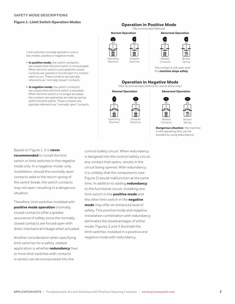
Figure 1. Limit Switch Operation Modes
SAFETY MODE DESCRIPTIONS
Operation in Negative Mode(Not recommended method for stand-alone only)
Operation in Positive Mode(Recommended Method)
OperatingMachine
StoppedMachine
WeldedContacts
BrokenSpring
WeldedContacts
BrokenSpring
OperatingMachine
StoppedMachine
Normal Operation Abnormal Operation
Limit switches normally operate in one or two modes, positive or negative mode.
• In positive mode, the switch contact(s) are closed when the limit switch is not actuated. When the limit switch is actuated the closed contacts are opened or forced open if a contact weld occurs. These contacts are typically referred to as “normally closed” contacts.
• In negative mode, the switch contact(s) are closed when the limit switch is actuated. When the limit switch is no longer actuated, the contacts are opened by an internal spring within the limit switch. These contacts are typically referred to as “normally open” contacts.
Dangerous situation: the machine is still operating (this can be avoided by using redundancy)
The contact is still open and the machine stops safely
Normal Operation Abnormal Operation
Based on Figure 1, it is never recommended to install the limit
switch or limit switches in the negative
mode only. In a negative-mode-only
installation, should the normally open
contacts weld or the return spring of
the switch break, the switch contacts
may not open, resulting in a dangerous
situation.
Therefore, limit switches installed with
positive mode operation (normally
closed contacts) offer a greater
assurance of safety since the normally
closed contacts are forced open with
direct mechanical linkage when actuated.
Another consideration when specifying
limit switches for a safety-related
application is whether redundancy (two
or more limit switches with contacts
in series) can be incorporated into the
control/safety circuit. When redundancy
is designed into the control/safety circuit,
any contact that opens, results in the
circuit being opened. With redundancy,
it is unlikely that the components (see
Figure 2) would malfunction at the same
time. In addition to adding redundancy
to the functional circuit, installing one
limit switch in the positive mode and
the other limit switch in the negative mode may offer an enhanced level of
safety. This positive mode and negative
installation combination with redundancy
eliminates the disadvantages of either
mode. Figures 2 and 3 illustrate the
limit switches installed in a positive and
negative mode with redundancy.
APPLICATION NOTE | Fundamentals of Limit Switches with Positive-Opening Contacts | sensing.honeywell.com 3
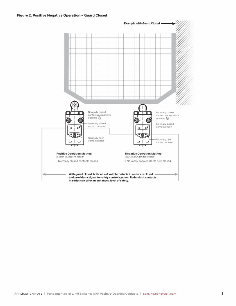
Figure 2. Positive Negative Operation – Guard Closed
Normally open contacts closed
Normally closed contacts open
Normally closed contacts are positive opening
Positive Operation Method (Switch plunger released)
With guard closed, both sets of switch contacts in series are closed and provides a signal to safety control system. Redundant contacts in series can offer an enhanced level of safety.
• Normally closed contacts closed
Negative Operation Method (Switch plunger depressed)
Example with Guard Closed
• Normally open contacts held closed
Normally open contacts open
Normally closed contacts closed
Normally closed contacts are positive opening

APPLICATION NOTE | Fundamentals of Limit Switches with Positive-Opening Contacts | sensing.honeywell.com 4
Figure 3. Positive Negative Operation – Guard Open
With guard open, both sets of switch contacts in series are open and provides no signal to safety control system. With redundancy, should one contact malfunction and remain closed, the other contact is open and the circuit is open.
Positive Operation Method (Switch plunger depressed)
• Normally closed contacts held open
Example with Guard Open
Normally open contacts open
Normally closed contacts closed
Normally closed contacts are positive opening
Normally open contacts closed
Normally closed contacts open
Normally closed contacts are positive opening
Negative Operation Method (Switch plunger released)
• Normally open contacts open

APPLICATION NOTE | Fundamentals of Limit Switches with Positive-Opening Contacts | sensing.honeywell.com 5
Table 1. Honeywell MICRO SWITCH Limit Switch Series with Positive-Opening, Normally Closed (NC) Contacts
EN50041 Global Limit Switches
GLA Series, metal housing, non-plug-inGLB Series, metal housing, plug-inGLF Series, metal housing, non-plug-in, 1 LED GLG Series, metal housing, plug-in, 1 LEDGLH Series, metal housing, non-plug-in, 2 LEDs
EN50047 Global Limit Switches
GLC Series, metal housing, non-plug-inGLD Series, plastic housing, non-plug-in GLE Series, plastic housing, non-plug-inGLL Series, plastic housing, non-plug-in
EN50041 Safety Series Limit Switches
GSA Series, metal housing, non-plug-in
Miniature Limit Switch Series
NGC Series, (miniature) metal or plastic housingSZL-VL-S Series, (miniature) with side rotary actuator24CE Series, (miniature) safety switch with metal housing924CE Series, (miniature) safety switch with metal housing
Hazardous Location Safety Switch Series
GSX Series, hazardous location switch with metal housing
Cable- and Rope Pull Switches
1CPS Series, single head cable/rope pull with metal housing2CPS Series, dual head cable/rope pull with metal housingCLSX Series, single head cable/rope pull with metal housing for hazardous locations
Key Interlock Safety Switches
GK Series, EN50041 mounting, metal housingGKE Series, EN50047 mounting, plastic housingGKM Series, miniature with metal housingGKN Series, plastic housing
THIS APPLICATION NOTE CONTAINS CLICKABLE LINKS...To review the datasheet for a particular series of limit switches with positive-opening contacts, click on the Series name below.

002427-2-EN | 2 | 09/19© 2019 Honeywell International Inc. All rights reserved.
Honeywell Sensing and Internet of Things9680 Old Bailes Road
Fort Mill, SC 29707
honeywell.com
FOR MORE INFORMATION
Honeywell Sensing and Internet of
Things services its customers through a
worldwide network of sales offices and
distributors. For application assistance,
current specifications, pricing, or the
nearest Authorized Distributor,
visit sensing.honeywell.com or call:
International +815 618 3231
USA/Canada +302 613 4491
WARRANTY/REMEDY
Honeywell warrants goods of its manufacture as being free of defective materials and faulty workmanship during the applicable warranty period. Honeywell’s standard product warranty applies unless agreed to otherwise by Honeywell in writing; please refer to your order acknowledgement or consult your local sales office for specific warranty details. If warranted goods are returned to Honeywell during the period of coverage, Honeywell will repair or replace, at its option, without charge those items that Honeywell, in its sole discretion, finds defective. The foregoing is buyer’s sole remedy and is in lieu of all other warranties, expressed or implied, including those of merchantability and fitness for a particular purpose. In no event shall Honeywell be liable for consequential, special, or indirect damages.
While Honeywell may provide application assistance personally, through our literature and the Honeywell web site, it is buyer’s sole responsibility to determine the suitability of the product in the application.
Specifications may change without notice. The information we supply is believed to be accurate and reliable as of this writing. However, Honeywell assumes no responsibility for its use.
mWARNINGIMPROPER INSTALLATION• Consult with local safety agencies
and their requirements when designing a machine control link, interface and all control elements that affect safety.
• Strictly adhere to all installation instructions.
Failure to comply with these instructions could result in death or serious injury.