
FUNDAMENTALS DESIGN OF HEAT EXCHANGER · PDF fileFoundation of Technical Education College of...
33
Foundation of Technical Education College of Technical/ Basrah 4 Lectures FUNDAMENTALS & DESIGN OF HEAT EXCHANGER 1. Classification of Heat Exchangers 2. Calculations of Heat Exchanger 3. Heat Transfer Applications 4. Construction of Shell-And-Tube Heat Exchangers Lecturer Mr. Amjed Ahmed Ali
Transcript of FUNDAMENTALS DESIGN OF HEAT EXCHANGER · PDF fileFoundation of Technical Education College of...

Foundation of Technical Education
College of Technical/ Basrah
4 Lectures
FUNDAMENTALS & DESIGN OF HEAT EXCHANGER
1. Classification of Heat Exchangers 2. Calculations of Heat Exchanger 3. Heat Transfer Applications 4. Construction of Shell-And-Tube Heat Exchangers
Lecturer
Mr. Amjed Ahmed Ali

Heat Exchanger College of Technical
Mr. Amjed Ahmed 2
HEAT EXCHANGER 1 PREFACE A Heat Exchanger: heat energy is transferred from one body or fluid stream to
another. heat transfer equations are applied to calculate this transfer of energy so as to carry it out efficiently and under controlled conditions. The equipment goes under many names, such as boilers, pasteurizers, jacketed pans, freezers, air heaters, cookers, ovens and so on. The purpose of the heat exchanger is :
1. To heat or cool a stream flowering from equipment to another. 2. To vaporize a liquid stream 3. To condensate a vapor stream. 2 CLASSIFICATION OF HEAT EXCHANGERS:
2.1. TYPES OF APPLICATION a. Boilers and Steam Generators b. Condensers c. Radiators d. Evaporators e. Cooling towers (direct contact) f. Regenerators (periodic heat flow hot and cold fluid alternately occupy
the space of the heat exchanger) g. Recuperates (continuous heat flow hot and cold fluid are separated by
a wall–shell and tube heat exchangers) 2.2 FLUID FLOW ARRANGEMENT
a) Co-current or parallel flow : The fluids can flow in the same direction through the equipment
b) Countercurrent flow: The fluids can flow in the opposite directions through the equipment
c) Cross flow: they can flow at right angles to each other.

Heat Exchanger College of Technical
Mr. Amjed Ahmed 3
Fig.(1) Double Pipe Heat Exchanger 2.3 Mixed and Unmixed fluid:
a. Both fluids unmixed b. One fluid mixed another unmixed c. Both fluids mixed
Fig.(2) Mixed and Unmixed fluid 3 CONTINUOUS-FLOW HEAT EXCHANGERS It is very often convenient to use heat exchangers in which one or both of the
materials that are exchanging heat are fluids, One of the fluids is usually passed through pipes or tubes, and the other fluid stream is passed round or across these. Most actual heat exchangers of this type have a mixed flow pattern, but it is often possible to treat them from the point of view of the predominant flow pattern.
3.1 DOUBLE-PIPE HEAT EXCHANGER A double-pipe heat exchanger is constructed from two pipes, one inside the
other. First fluid flows inside the inner pipe while the second fluid flows in the annular space between the two pipes. To obtain larger heat exchange area, several pipes are arranged side-by-side and fittings are attached to allow the fluids to contact the pipes in series.
Fig.(3) Double-Pipe Heat exchanger 3.2 SHELL-AND-TUBE HEAT EXCHANGER If very large heat exchange areas are required. Shown below is a bundle of
small-diameter tubes which are arranged parallel to each other and reside inside a much larger-diameter tube called the "shell", much like strands of uncooked Spagetti come in a tube-shaped container. The tubes are all manifolded together at either end so
1-1 Heat Exchanger that the "tube fluid" enters the left side and is distributed equally among all the tubes. At the right side, the fluid exits from each tube, is mixed together in a second manifold, then leaves as a single stream. The second fluid flows in the space in between the outside of tubes. Baffle plates inside the shell force the shell fluid to flow across the tubes repeatedly as the fluid moves along the length of the shell.
1-2 Heat Exchanger Half of the tubes have flow from left to right while the

Heat Exchanger College of Technical
Mr. Amjed Ahmed 4
other half have flow in the opposite direction.
1 pass of shell-1 pass of tubes
1 pass of shell-2 pass of tubes
2 pass of shell-4 pass of tubes
Fig.(4) Different type of shell and tube Heat exchanger

Heat Exchanger College of Technical
Mr. Amjed Ahmed 5
4 TYPES OF HEATING AND COOLING CURVES:
(c) Ch>>Cc or a condensing vapor (d) Ch<<Cc or an evaporating liquid
(e) Hot and cold fluid Changing phase (f) Hot fluid Changing phase
(g) cold fluid Changing phase (h) condensable and noncondensable components
Fig(11) Temperature distribution for a different counter current heat exchanger.
Tc out Th out
Th in
Tc in
Tc in
Th out Th in Tc out
Tc in Th out
Th in
Tc out
Tc in
Th out Th in
Tc out Tc in
Th out Th in
Tc out
Tc in
Th out Th in
Tc out
Tc in Th out
Th in
Tc out
Heating
Heating
Superheating Heating
Cooling
Condensing
Evaporating
Evaporating
Condensing
Desuperheating Subcooling
Partial
Condensing

Heat Exchanger College of Technical
Mr. Amjed Ahmed 6
4 HEAT TRANSFER CALCULATIONS The primary objective in the thermal design of heat exchangers is to determine
the necessary surface area required to transfer heat at a given rate for given fluid temperatures and flow rates. the fundamental heat transfer relation
q = UA∆T (1) the overall heat transfer coefficient U is proportional to the reciprocal of the
sum of the thermal resistances. For the common configurations which we shall encounter; cylindrical wall:
ii
o
i
oo
o
o
hrr
rr
kr
h
U1ln1
1
⎟⎟⎠
⎞⎜⎜⎝
⎛+⎟⎟⎠
⎞⎜⎜⎝
⎛+
= (2)
ii
oi
oo
ii
hrr
kr
hrr
U1ln1
1
+⎟⎟⎠
⎞⎜⎜⎝
⎛+⎟⎟
⎠
⎞⎜⎜⎝
⎛= (3)
UA=UoAo=UiAi where subscripts i and o represent the inside and outside surfaces of the wall,
respectively, the overall heat transfer coefficient and the surface area must be compatible, i.e.,
q = UoAo∆T = UiAi∆T (1) Table(1) gives approximate values of U for some commonly encountered fluids.
The wide range of values cited results: 1. A diversity of heat exchanger materials (of different k value) 2. A flow conditions (influencing the film coefficients, h), 3. Geometric configuration.

Heat Exchanger College of Technical
Mr. Amjed Ahmed 7
Table(1) Overall Heat Transfer Coefficient
Fouling Resistance The performance of heat exchangers depends upon the heat transfer surfaces
being clean and uncorrected. Should surface deposits be present, thermal resistance increases, resulting in decreased performance. This added resistance is usually accounted for by a fouling factor (Fouling Resistance, Rf) which must be included along with other thermal resistances when calculating the overall heat transfer coefficient.
ii
ofi
i
o
i
oofo
o
o
hrrR
rr
rr
krR
h
U1ln1
1
⎟⎟⎠
⎞⎜⎜⎝
⎛+⎟⎟
⎠
⎞⎜⎜⎝
⎛+⎟⎟
⎠
⎞⎜⎜⎝
⎛++
= (4)
ifi
i
oifo
o
i
oo
ii
hR
rr
krR
rr
hrr
U1ln1
1
++⎟⎟⎠
⎞⎜⎜⎝
⎛+⎟⎟
⎠
⎞⎜⎜⎝
⎛+⎟⎟
⎠
⎞⎜⎜⎝
⎛= (5)
Typical values of R, (m2.K/W) range from 0.00009 for clean vapors to 0.0002 for hot river water.
1. Material deposits on hot surfaces

Heat Exchanger College of Technical
Mr. Amjed Ahmed 8
2. Rust impurities 3. Strong effect when boiling occurs
Clean After some time
Fig.(5) fouling resistance in double pipe heat exchanger
5 LOG-MEAN TEMPERATURE DIFFERENCE(LMTD METHOD) 5.1 DOUBLE-PIPE HEAT EXCHANGER A parallel-flow flat-plate exchanger, whose temperature profiles are shown in
Fig.(2) We shall assume that: 1. U is constant 2. heat exchange takes place only between the two fluids 3. the temperatures of both fluids are constant over a given cross-section 4. the specific heats of the fluids are constant
Fig.(6) The ∆T1 and ∆T2 expressions in parallel-flow and counter-flow heat
exchanger
∆T1
∆T2
Rfo
Rfi
dA

Heat Exchanger College of Technical
Mr. Amjed Ahmed 9
the heat transfer between the hot and cold fluids for a differential length dx is dq = UdA(Th-Tc) (6)
since dA is the product of length dx and a constant width. The energy gained by the cold fluid is equal to that given up by the hot fluid,
dq = mcCcdTc= -mhChdTh (7) where m is the mass flow rate and C is the specific heat. Solving for the
temperature differentials from equation (7),
ccc Cm
dqdT = hh
h CmdqdT =
Taking Their difference, we get;
)11(cchh
ch CmCmdqdTdT +−=− (8)
Eliminating dq between (6) and (8) yields
)11)(()(cchh
chch CmCmTTUATTd +−−=− (9)
)11()()(2
1 cchhch
ch
CmCmUA
TTTTd
+−=−−
∫
which integrates to give
(10) where the ∆T terms are as shown in Fig. (5). And From an energy balance on
each fluid,
and substitution of these expressions into (10) gives
or, in terms of the differences in end temperatures,
(11) Upon comparing this result with eq.(1) , we see that
lmTTTTTT ∆=∆∆∆−∆
=∆)/ln( 12
12

Heat Exchanger College of Technical
Mr. Amjed Ahmed 10
This average effective temperature difference is called the log-mean temperature difference (LMTD). It can easily be shown that the subscripts 1 and 2 may be interchanged without changing the value of ∆Tlm.
5.2 MULTIPASS AND CROSS-FLOW HEAT EXCHANGERS For more complex heat exchangers, such as those involving multiple tubes,
several shell passes, or cross flow, determination of the average effective temperature difference is so difficult that the usual practice is to modify (1) by a correction factor, giving
q = UAF∆Tlm (1.3)
Correction factors F for several common configurations are given in Fig.(6). In these figures the notation (T1,T2 , t1, t2 ) to denote the temperatures of the two fluid streams has been introduced, since it is immaterial whether the hot fluid flows through the shell or the tubes.
It is normally correlated as a function of two dimensionless temperature ratios:

Heat Exchanger College of Technical
Mr. Amjed Ahmed 11

Heat Exchanger College of Technical
Mr. Amjed Ahmed 12

Heat Exchanger College of Technical
Mr. Amjed Ahmed 13
EXAMPLE 1 In a counter flow heat exchanger, water is being chilled by a sodium chloride
brine. If the rate of flow of the brine is 1.8 kg/s and that of the water is 1.05 kg/s , estimate the temperature to which the water is cooled if the brine enters at -8°C and leaves at 10°C, and if the water enters the exchanger at 32°C. If the area of the heat-transfer surface of this exchanger is 55 m2, what is the overall heat-transfer coefficient? Take the specific heats to be 3.38 and 4.18 kJ/kg °C for the brine and the water respectively.
Solution By heat balance, heat loss in brine = heat gain in water
1.8 x 3.38 x [10 - (-8)] = 1.05 x 4.18 x (32 - Tw2) Tw2 = 7°C.
for counterflow
∆T1 = [32 - 10] = 22°C and ∆T2 = [7 - (-8)] = 15°C. ∆Tm = (22 - 15)/ln(22/15) = 18.3°C. q= UA∆Tm
Therefore 3.38 x 1.8 x 18 = U x 55 x 18.3 U = 0.11 kJ/m2 °C
EXAMPLE 2 Determine the heat transfer surface area and length required for a heat
exchanger constructed from a 0.0254m OD tube to cool 6.93 kg/s of a 95% ethyl alcohol solution (cp = 3810 J/kg K) from 65.6°C to 39.4°C, using 6.30 kg/s of water available at 10°C (cp = 4187 J/kg K). Assume that the overall coefficient of heat transfer based on the outer-tube area is 568 W/m2 K and consider each of the following arrangements:
(a) Parallel-flow tube and shell (b) Counterflow tube and shell (c) Counterflow exchanger with 2 shell passes and 72 tube passes, the
alcohol flowing through the shell and the water flowing through the tubes (d) Cross-flow, with one tube pass and one shell pass, shell-side fluid mixed SOLUTION (a) Writing the energy balance as
mh cph (Th,in - Th out) = mccpc (Tc,out – Tc, in) we obtain
(6.93)(3810)(65.6 - 39.4) = (6.30)(4187)(Tc,out - 10) Tc, out=36.2°C
The rate of heat flow from the alcohol to the water is
q =mhcph (Th,in – Th,out) q =(6.93 kg/s)(3810 J/kg K)(65.6 - 39.4)(K) q = 691,800 W
=∆∆∆−∆
=∆)/ln( 12
12
TTTTTlm
From the heat transfer surface area is

Heat Exchanger College of Technical
Mr. Amjed Ahmed 14
0.0254m OD tube L=A/πD = 830 m
(b) For the counterflow arrangement, LMTD=65.6-36.2 = 29.4°C, because mccpc = mhcph. The required area is
which is about 40% less than the area necessary for parallel flow.
(c) For the counterflow arrangement, we determine the appropriate
mean temperature difference by applying the correction factor found from Fig.12.20 to the mean temperature for counterflow:
and the heat capacity rate ratio is
From the chart of Fig. 14, F = 0.97 and the heat transfer area is
The length of the exchanger for seventy-two 0.0254 m OD tubes in parallel
would be
(d) For the cross-flow arrangement Fig.(2)b , the correction factor is found from
the chart of Fig. 8.15 to be 0.88. The required surface area is thus 47.0 m2, about 10% larger than that for the reversed-current exchanger.

Heat Exchanger College of Technical
Mr. Amjed Ahmed 15
6 HEAT EXCHANGER EFFECTIVENESS (NTU METHOD) Another approach introduces a definition of heat exchanger effectiveness ε :
maxqqε = (13)
Where: 0 ≤ ε ≤ 1 and ε =0 (evaporation & condensation) q : Actual heat transfer qmax: maximum possible heat transfer is that which would result if one fluid
underwent a temperature change equal to the maximum temperature difference (Thi - Tci)
This method uses the effectiveness ε to eliminate the unknown discharge temperature and gives a solution for effectiveness in terms of other known parameters (m, C, A, and U). Letting C = mc,
q=Ch(Thi-Tho) =Cc(Tco-Tci) (15)
The maximum possible heat transfer occurs when the fluid of smaller C undergoes the maximum temperature difference available,
qmax = Cmin( Thi - Tci) (16)
This transfer would be attained in a counterflow exchanger of infinite area. Combining (14) and (16),we get the basic equation for determining the heat transfer in heat exchangers with unknown discharge temperatures:
qactual = ε Cmim (Thi - Tci) (17) 6.1 PARALLEL-FLOW HEAT EXCHANGER Consider the simple parallel-flow heat exchanger of Fig.(5) under the same
assumptions used in Section 5.1 to determine the log-mean temperature difference. Combining (13), (14) and (I5) , we get two expressions for effectiveness,
)T-(TC)T-(TC
)T-(TC)T-(TC
cihimin
cicoc
cihimin
hohih ==ε (18)
Since either the hot or the cold fluid may have the minimum value of C, there are two possible values of effectiveness:
)20(T-TT-Toncondensati
)19(T-TT-Tn evaporatio
cihi
cico
cihi
hohi
=>
=<
cch
hch
CC
CC
ε
ε
where subscripts on ε designate the fluid which has the minimum C. Returning to (9), it may be written in terms of the Cs to give
⎟⎟⎠
⎞⎜⎜⎝
⎛⎟⎟⎠
⎞⎜⎜⎝
⎛+−=
−
c
h
h CC
CUA 1exp
T-TTT
cihi
coho
From the energy balance equation (15),
Tco = Tci +Ch /Cc (Thi-Tho) (22)
Substituting this relation in to eq. (21) after adding and subtracting Thi gives

Heat Exchanger College of Technical
Mr. Amjed Ahmed 16
⎥⎦
⎤⎢⎣
⎡⎟⎟⎠
⎞⎜⎜⎝
⎛+−=
−+−
c
h
hcihi
hohichcihihiho
CC
CUA
-TT))-T (T /C +C(TTTT 1exp
Which simplified to:
⎥⎦
⎤⎢⎣
⎡⎟⎟⎠
⎞⎜⎜⎝
⎛+−=
+−−
c
h
hcihi
hohichhohi
cihi
cihi
CC
CUA
-TT)-T (T /CCTT
-TT-TT 1exp
⎥⎦
⎤⎢⎣
⎡⎟⎟⎠
⎞⎜⎜⎝
⎛+−−=
+−
c
h
hcihi
hohichhohi
CC
CUA
-TT)-T (T /CCTT 1exp1)(
) /CCCC
CUA
-TTTT
ch
c
h
h
cihi
hohi
+
⎥⎦
⎤⎢⎣
⎡⎟⎟⎠
⎞⎜⎜⎝
⎛+−−
=−
1(
1exp1)(
Substituting this relation in to equation (19)
(23) similarity in to eq.(20) we get,
(24) Equations (23) and (24) may both be expressed as
(25) It should be noted that (25) contains only the overall heat transfer coefficient,
area, fluid properties, and flow rates. Giving the effectiveness for a parallel-flow heat exchanger in terms of two
dimensionless ratios (UA/Cmin) and (Cmin/Cmax), a UA/Cmin, is called the Number of Transfer Units may be considered as a heat exchanger size factor,
NTU = UA/Cmin (26)
D

Heat Exchanger College of Technical
Mr. Amjed Ahmed 17
(mCp)hot > (mCp)cold (mCp)cold > (mCp)hot Cmin = (mCp)cold Cmin = (mCp)hot ∆Tc >∆Th ∆Th > ∆Tc
A=∞ A=∞
q=(mCp)cold (Thi-Tci) q=(mCp)hot (Thi-Tci)
Tc in
Th out
Th in Tc out ∆Th
∆Tc
Tc in Th out
Th in
Tc out ∆Th
∆Tc
Tc in
Th out
Th in= Tc out A=∞
Tc in= Th out
Th in
Tc out

Heat Exchanger College of Technical
Mr. Amjed Ahmed 18
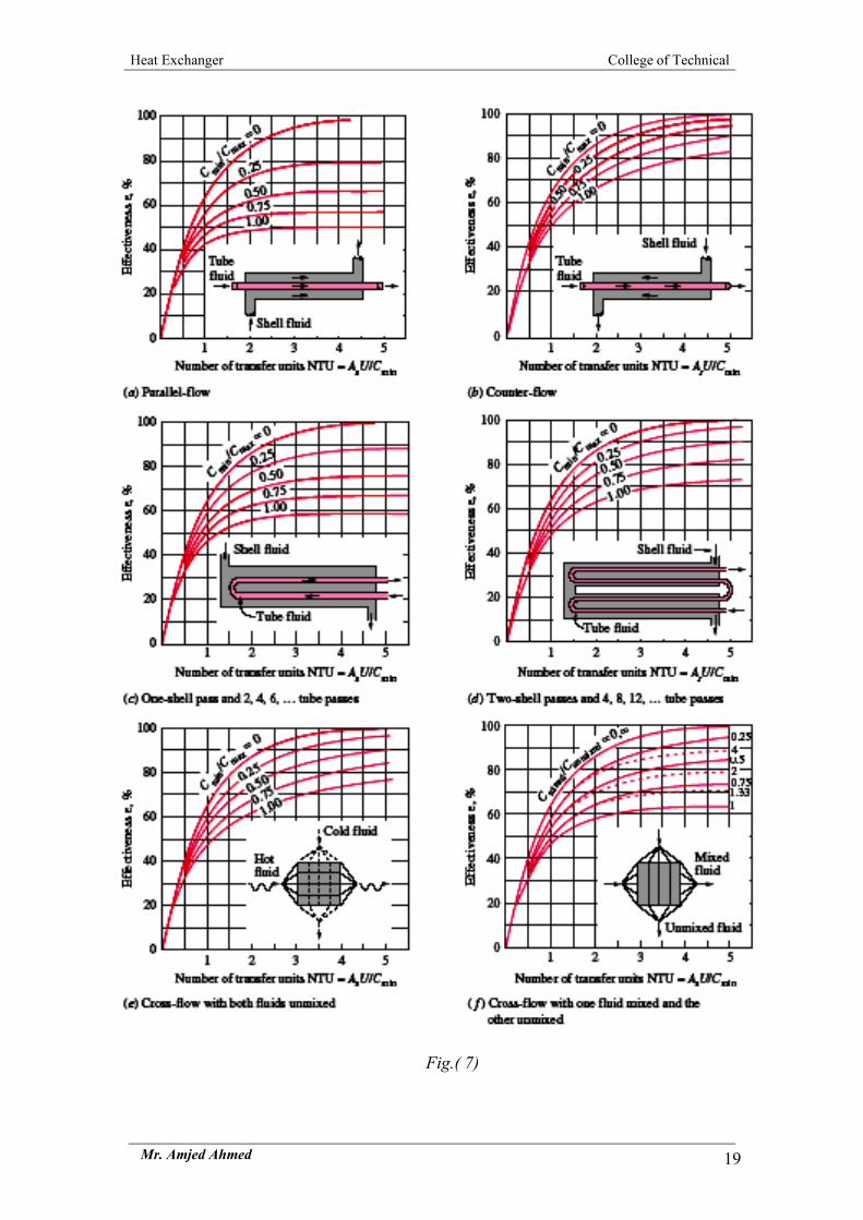
Table (2) Expressions for the effectiveness of other configurations where
C=Cmin/Cmax
Note that for an evaporator or condenser C = 0, because one fluid remains at a
constant temperature, making its effective specific heat infinite.
Heat Exchanger College of Technical
Mr. Amjed Ahmed 19
Fig.( 7)

Heat Exchanger College of Technical
Mr. Amjed Ahmed 20
Example 4 From a performance test on a well-baffled single-shell, two-tube-pass heat
exchanger, the following data are available: oil (cp = 2100 J/kg K) in turbulent flow inside the tubes entered at 340 K. at the rate of 1.00 kg/s and left at 310 K; water flowing on the shell side entered at 290 K and left at 300 K.
A change in service conditions requires the cooling of a similar oil from an initial temperature of 370 K but at three fourths of the flow rate used in the performance test. Estimate the outlet temperature of the oil for the same water flow rate and inlet temperature as before.
Solution
qh=qc Ch(Thi-Tho)= Cc(Tco-Tci) Cc= 6300 W/K
and the temperature ratio P is, from Eq. (8.19),
S=0.6 R=0.33 From Fig. 8.13. F = 0.94
the overall conductance is
Since the thermal resistant on the oil side is controlling, a decrease in velocity to 75% of the original value will increase (he thermal resistance by roughly the velocity ratio raised to the 0.8 power.
Under the new conditions, the conductance, the NTU, and the heat capacity rate ratio will therefore be approximately
UA =(2325)(0.75)0.8 = 1850 W/K
NTU=UA/Coil =1.17 Cmin=Coil =0.75×1.00 kg/s)(2100 J/kg K) Cmax=Cwater=6300 W/K
Cmin/ Cmax=0.25
from Fig. 8.19 the effectiveness is equal to 0.61. Hence
Toil out = Toil in – ε ∆Tmax. = 370 - [0.61(370 - 290)] = 321.2 K.

Heat Exchanger College of Technical
Mr. Amjed Ahmed 21
7 OTHER HEAT TRANSFER APPLICATIONS 7.1 JACKETED PANS In a jacketed pan, the liquid to be heated is contained in a vessel, which may
also be provided with an agitator to keep the liquid on the move across the heat-transfer surface, as shown in Fig.3(a).
The source of heat is commonly steam condensing in the vessel jacket. Practical considerations of importance are:
1. There is the minimum of air with the steam in the jacket. 2. The steam is not superheated as part of the surface must then be used as a de-
superheater over which low gas heat-transfer coefficients apply rather than high condensing coefficients.
3. Steam trapping to remove condensate and air is adequate. Some overall heat transfer coefficients are shown in Table 3. Save for boiling
water, which agitates itself, mechanical agitation is assumed. Where there is no agitation, coefficients may be halved.
Table(3) Some Overall Heat Transfer Coefficients In Jacketed Pans
Condensing fluid Heated fluid Pan material U (J/m2 s °C) Steam Thin liquid Cast-iron 1800 Steam Thick liquid Cast-iron 900 Steam Paste Stainless steel 300 Steam Water, boiling Copper 1800
7.2 HEATING COILS IMMERSED IN LIQUIDS In some processes, quick heating is required in the pan, a helical coil may be
fitted inside the pan and steam admitted to the coil as shown in Fig.3(b). This can give greater heat transfer rates than jacketed pans, because there can be a greater heat transfer surface and also the heat transfer coefficients are higher for coils than for the pan walls.
(a) Jacketed pans (b) Heating Coil
Fig.(8) Heat exchange equipment
Steam
Condensate
Heat Exchanger College of Technical
Mr. Amjed Ahmed 22
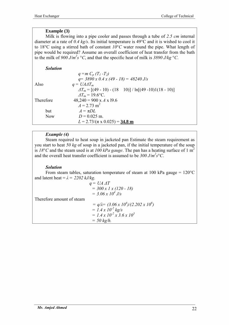
Example (3) Milk is flowing into a pipe cooler and passes through a tube of 2.5 cm internal
diameter at a rate of 0.4 kg/s. Its initial temperature is 49°C and it is wished to cool it to 18°C using a stirred bath of constant 10°C water round the pipe. What length of pipe would be required? Assume an overall coefficient of heat transfer from the bath to the milk of 900 J/m2s °C, and that the specific heat of milk is 3890 J/kg °C.
Solution
q =m Cp (T1 -T2) q= 3890 x 0.4 x (49 - 18) = 48240 J/s
Also q = UA∆Tm ∆Tm = [(49 - 10) - (18 10)] / ln[(49 -10)1(18 - 10)] ∆Tm = 19.6°C.
Therefore 48,240 = 900 x A x l9.6 A = 2.73 m2
but A = πDL Now D = 0.025 m.
L = 2.73/(π x 0.025) = 34.8 m Example (4) Steam required to heat soup in jacketed pan Estimate the steam requirement as
you start to heat 50 kg of soup in a jacketed pan, if the initial temperature of the soup is 18°C and the steam used is at 100 kPa gauge. The pan has a heating surface of 1 m2
and the overall heat transfer coefficient is assumed to be 300 J/m2s°C. Solution From steam tables, saturation temperature of steam at 100 kPa gauge = 120°C
and latent heat = λ = 2202 kJ/kg. q = UA ∆T
= 300 x 1 x (120 - 18) = 3.06 x 10⁴ J/s Therefore amount of steam
= q/λ= (3.06 x 10⁴)/(2.202 x 106) = 1.4 x 10⁻² kg/s = 1.4 x 10-2 x 3.6 x 103 = 50 kg/h.

Heat Exchanger College of Technical
Mr. Amjed Ahmed 23
7.3 SCRAPED SURFACE HEAT EXCHANGERS The processing industry particularly for products of higher viscosity, consists of
a jacketed cylinder with an internal cylinder concentric to the first and fitted with scraper blades, as illustrated in Fig.(9). The blades rotate, causing the fluid to flow through the annular space between the cylinders with the outer heat transfer surface constantly scraped. Coefficients of heat transfer vary with speeds of rotation but they are of the order of 900-4000 J/m2s°C. These machines are used in the freezing of ice cream and in the cooling of fats during margarine manufacture.
Fig.(9) Heat exchange equipment
7.4 PLATE HEAT EXCHANGERS A popular heat exchanger for fluids of low viscosity, is the plate heat exchanger,
where heating and cooling fluids flow through alternate tortuous passages between vertical plates as illustrated in Fig.(10). The plates are clamped together, separated by spacing gaskets, and the heating and cooling fluids are arranged so that they flow between alternate plates. Suitable gaskets and channels control the flow and allow parallel or counter current flow in any desired number of passes. A substantial advantage of this type of heat exchanger is that it offers a large transfer surface that is readily accessible for cleaning. The banks of plates are arranged so that they may be taken apart easily. Overall heat transfer coefficients are of the order of 2400-6000 J/m2s°C.

Heat Exchanger College of Technical
Mr. Amjed Ahmed 24
Fig.(10) Plate Heat exchange

Heat Exchanger Design College Of Technical
Mr. Amjed Ahmed 25
8 A DESIGN METHODOLOGY 1. Heat Exchanger Sizing Choose a typical value for U based on the type of
service, then determined the outlet temperatures based on the performance specifications (number of tube, baffle spacing, …etc) and the energy balance Q also calculate heat transfer area from Q=UAF∆Tlm.
2. Heat Exchanger Rating is the computational process in which the inlet flow rate and temperatures, the fluid properties and the heat exchanger parameter are taken as input. And the outlet temperatures and thermal duty Q (if the heat exchanger length is specified) on the required length is calculated as output else pressure drop of each stream. (U and A are known)
3. Heat Exchanger Design Is the process that determine the heat exchanger specifications such as (length and diameter of tube, shell thickness, spacing and cut baffle.)
• Determine heat transfer area based on sizing calculation • Determine number of tube and pass • Check the velocity if below acceptable range, choose suitable number of pass. • Calculate overall heat transfer coefficient and estimate the fouling resistance. • Check |Uassume -Ucalculate |< 0.001 • Check the pressure drop for shell and tube sides , then determine the pumping
power requirements for shell and tubes sides. 1. Kern Method
Kern Method is used to estimate the size of the heat exchanger for a given specification (Sizing Method), its restricted to a fixed baffecut (25%) and cannet adequately account for baffle-shell and tube-to-baffle leakages
Input (know) Output (unknown) Tci Tho Thi Q Tco di mh do mc
2. Bell Delaware's Method It's a rating analysis and give more satisfactory predications of the heat transfer
coefficient and pressure drop than Kern Method, and it is takes into account the effects of leakage and passing.
Data of Kern Method Data of Bell Method

Heat Exchanger Design College Of Technical
Mr. Amjed Ahmed 26
3. NTU Method It the heat duty is not known because only the inlet temperatures are given while
the outlet temperatures are not. On the other hand the heat exchanger length is fixed and the outlet temperatures and pressure drops are to be calculated.
Input (know) Output (unknown)
Tci Tho Thi Tco L di mh do mc ∆Ptubes ∆Pshell Q
4. F-Method When all of the terminal temperatures are known, than;
Q= UAF∆Tlm

Heat Exchanger Design College Of Technical
Mr. Amjed Ahmed 27
9. HEAT EXCHANGER DESIGN BY KERN METHOD
………………………………………. 1 ………………………………………. 2 ………………………………………. 3 ………………………………………. 4
………………………………………. 5 ………………………………………. 6 …………………. 7 ………………………………………. 8 ………………………………...…. 9 …………………………………... 10
Start
q =mCp(Tin -Tout) or q =mλ Calculate: t2 from Energy Balance
Calculate ( ) )ln(/1
212 T
TTTTlm ∆∆
∆−∆=∆
From Chart estimate: S,R Correction Factor
T1, T2, t1, Cph , Cpc
F < 0.85
Estimate: UAssume from Table(12.1) Calculate: A=q/UAssume F ∆Tlm
A <20 ft2
20≤A≤500 ft2
A >500 ft2
Select Coil Type
Select Double Pipe H.E. Type
Select Shell & Tube H.E. Type
1
3
2
Selection Tube Diameter(di, do) 3/8", 1/2", 1/4" Selection Tube Length (L) 8,10, 12, 16,20 ft
Choose Shell and Tube Passes
Yes
No
Select the type of flow Co-current ,Counter-current & Cross-flow
Estimate No. of Bundle Pass
Selection Another Type
Ao=πdoL No. of Tubes Np=Aoπ/DL or Np=A/Ao
Vt <2 m/s
Velocity fluid inside Tube VtSelection another di, do

Heat Exchanger Design College Of Technical
Mr. Amjed Ahmed 28
……………………………….…. 11 …………………………………. 12 ……………………………………. 13
……………………………………. 14 ……………………………………. 15 ……………………………………. 16 ………………………………….. 17 ………………………………….. 18 ………………………………….. 19
………………………………….. 20
………………………………….. 21
|U assume –U calculate |<0.05
ii
ofi
i
o
i
oofo
o hrr
Rrr
rr
kr
Rh
U1
ln1
1calculate
⎟⎟⎠
⎞⎜⎜⎝
⎛+⎟⎟
⎠
⎞⎜⎜⎝
⎛+⎟⎟
⎠
⎞⎜⎜⎝
⎛++
=
∆Ptube<10 Psi
∆P Tube
1
2
3
Selection tubes arrangement Triangular or Square Pitch
Baffle type & Space lB
Yes
Pumping Power of Tube (PPtube)
∆Pshell
No
No
No
End
Number of baffles Nb=(L/lB)-1
∆Pshell <3~7.3 Psi 3
Pumping Power of Shell (PPshell)
Shell Diameter Ds 8"~120"…
ho, hi
Uassume = Ucalculate
Yes
Yes

Heat Exchanger Design College Of Technical
Mr. Amjed Ahmed 29
Step 7. Choose tube type di and do
Assuming tube length (L) (6, 8, 12, 16) ft
Ao=πdoL Number of tube Nt = A/Ao
Step 12. Calculate the shell diameter Ds
a. [ ]22 )(637.0 PRNDCTKDs tOπ=
where K is the Tube layout constant K=1 for 90o and 45o K=0.87 for 30o and 60o CT is the tube count constant CT = 0.93 one tube pass CT = 0.90 Two tube pass CT = 0.85 Three tube pass PR is the tube Pitch ratio = Pt/do Pt is the tube Pitch
Fig(13) Tube patterns
b. Bundle Diameter Ds
Ds=Db + Clearance Db=do(Nt/K1)(1/n1)
Where K1 and n1 are constant from Table 12.4

Heat Exchanger Design College Of Technical
Mr. Amjed Ahmed 30
and clearance between bundle and the shell estimate from fig. (12.10)
Step 13. Baffle type & Space lB
5DslB =
or DslB )5.03.0( −=

Heat Exchanger Design College Of Technical
Mr. Amjed Ahmed 31
Step 14. Calculate heat transfer coefficient for inside tube hi
34.033.0PrRe ⎟⎟
⎠
⎞⎜⎜⎝
⎛==
wh
f
jKhidiNu
µµ
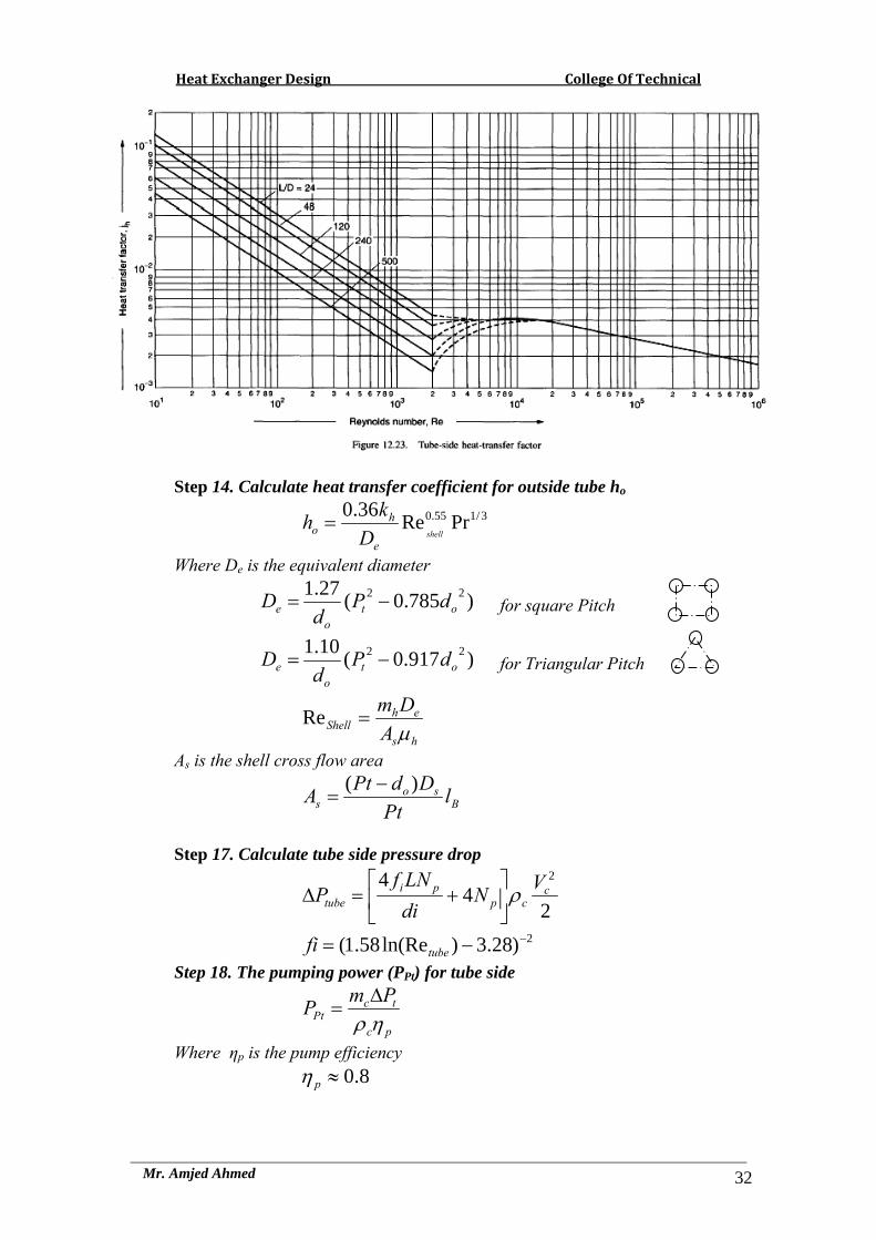
jh : heat transfer factor from fig.(12.23) Kf Thermal conductivity of the tube side fluid µw : Viscosity of the fluid at wall temperature Tw
⎥⎦⎤
⎢⎣⎡ +
++
=222
1 hohicociw
TTTTT
Heat Exchanger Design College Of Technical
Mr. Amjed Ahmed 32
Step 14. Calculate heat transfer coefficient for outside tube ho
3/155.0 PrRe36.0shell
e
ho D
kh =
Where De is the equivalent diameter
)785.0(27.1 22ot
oe dP
dD −= for square Pitch
)917.0(10.1 22ot
oe dP
dD −= for Triangular Pitch
hs
ehShell A
Dmµ
=Re
As is the shell cross flow area
Bso
s lPt
DdPtA )( −=
Step 17. Calculate tube side pressure drop
24
4 2c
cppi
tubeVN
diLNf
P ρ⎥⎦
⎤⎢⎣
⎡+=∆
2)28.3)ln(Re58.1( −−= tubefi Step 18. The pumping power (PPt) for tube side
pc
tcPt
PmPηρ∆
=
Where ηp is the pump efficiency 8.0≈pη

Heat Exchanger Design College Of Technical
Mr. Amjed Ahmed 33
Step 19. Calculate shell side pressure drop 14.02
28
−
⎟⎟⎠
⎞⎜⎜⎝
⎛⎟⎟⎠
⎞⎜⎜⎝
⎛⎟⎟⎠
⎞⎜⎜⎝
⎛⎟⎠⎞
⎜⎝⎛=∆
wBfshell
VlL
deDsjP
µµρ
Where jf is the fraction factor from fig.(12.30)
Step 20. The pumping power (PPshell) for shell side
ph
shellhPshell
PmPηρ∆
=
Step 21. Calculate the number of baffles
1−=B
b lLN