Functions and Compact NSX communication ... the BSCM module, the following information is...
10
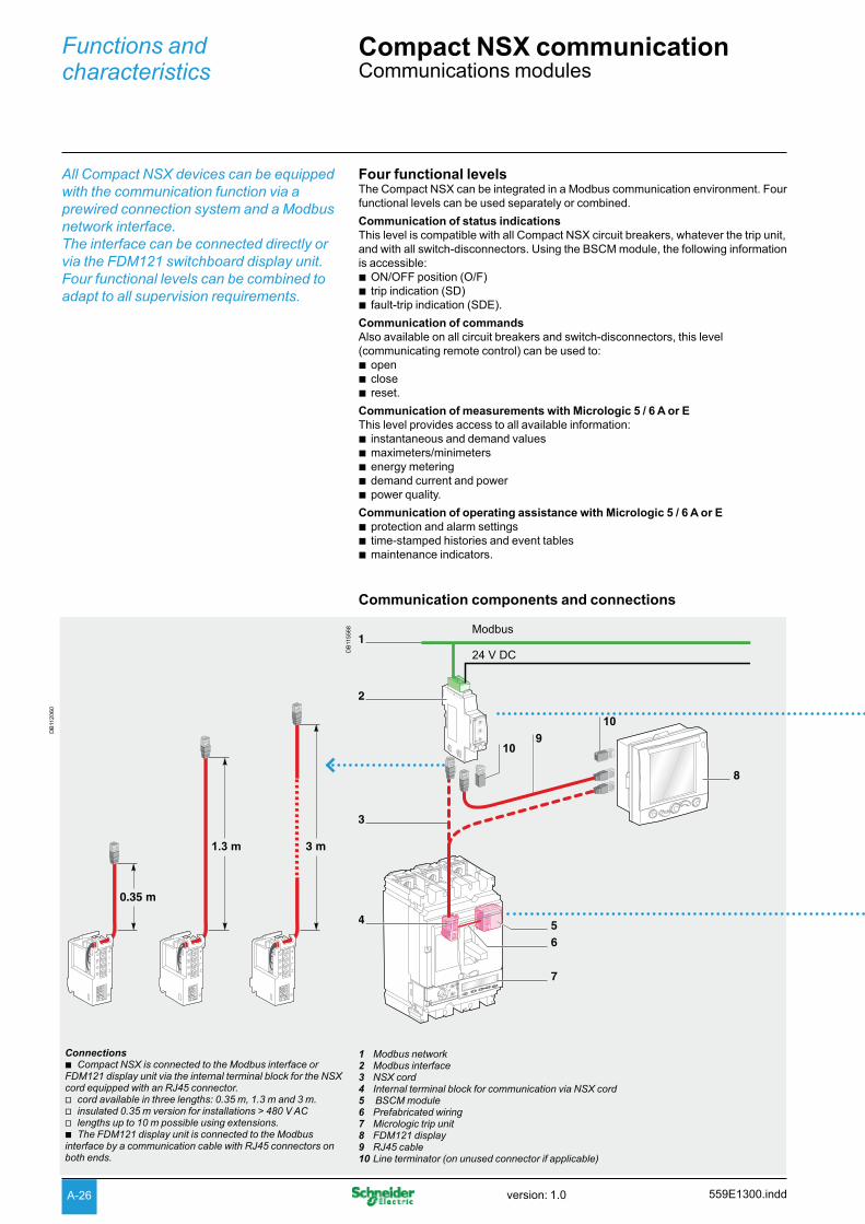
All Compact NSX devices can be equipped with the communication function via a prewired connection system and a Modbus network interface. The interface can be connected directly or via the FDM121 switchboard display unit. Four functional levels can be combined to adapt to all supervision requirements. A-26 Functions and characteristics Compact NSX communication Communications modules Four functional levels The Compact NSX can be integrated in a Modbus communication environment. Four functional levels can be used separately or combined. Communication of status indications This level is compatible with all Compact NSX circuit breakers, whatever the trip unit, and with all switch-disconnectors. Using the BSCM module, the following information is accessible: ON/OFF position (O/F) b trip indication (SD) b fault-trip indication (SDE). b Communication of commands Also available on all circuit breakers and switch-disconnectors, this level (communicating remote control) can be used to: open b close b reset. b Communication of measurements with Micrologic 5 / 6 A or E This level provides access to all available information: instantaneous and demand values b maximeters/minimeters b energy metering b demand current and power b power quality. b Communication of operating assistance with Micrologic 5 / 6 A or E protection and alarm settings b time-stamped histories and event tables b maintenance indicators. b 1 Modbus network 2 Modbus interface 3 NSX cord 4 Internal terminal block for communication via NSX cord 5 BSCM module 6 Prefabricated wiring 7 Micrologic trip unit 8 FDM121 display 9 RJ45 cable 10 Line terminator (on unused connector if applicable) Communication components and connections Connections Compact NSX is connected to the Modbus interface or b FDM121 display unit via the internal terminal block for the NSX cord equipped with an RJ45 connector. cord available in three lengths: 0.35 m, 1.3 m and 3 m. v insulated 0.35 m version for installations > 480 V AC v lengths up to 10 m possible using extensions. v The FDM121 display unit is connected to the Modbus b interface by a communication cable with RJ45 connectors on both ends. DB112060 1.3 m DB115568 Modbus 24 V DC 10 10 559E1300.indd version: 1.0
Transcript of Functions and Compact NSX communication ... the BSCM module, the following information is...
All Compact NSX devices can be equipped
with the communication function via a
prewired connection system and a Modbus
network interface.
The interface can be connected directly or
via the FDM121 switchboard display unit.
Four functional levels can be combined to
adapt to all supervision requirements.
A-26
Functions and characteristics
Compact NSX communication Communications modules
Four functional levelsThe Compact NSX can be integrated in a Modbus communication environment. Four
functional levels can be used separately or combined.
Communication of status indications
This level is compatible with all Compact NSX circuit breakers, whatever the trip unit,
and with all switch-disconnectors. Using the BSCM module, the following information
is accessible:
ON/OFF position (O/F) btrip indication (SD) bfault-trip indication (SDE). b
Communication of commands
Also available on all circuit breakers and switch-disconnectors, this level
(communicating remote control) can be used to:
open bclose breset. b
Communication of measurements with Micrologic 5 / 6 A or E
This level provides access to all available information:
instantaneous and demand values bmaximeters/minimeters benergy metering bdemand current and power bpower quality. b
Communication of operating assistance with Micrologic 5 / 6 A or E
protection and alarm settings btime-stamped histories and event tables bmaintenance indicators. b
1 Modbus network2 Modbus interface3 NSX cord4 Internal terminal block for communication via NSX cord5 BSCM module6 Prefabricated wiring7 Micrologic trip unit8 FDM121 display9 RJ45 cable10 Line terminator (on unused connector if applicable)
Communication components and connections
Connections
Compact NSX is connected to the Modbus interface or bFDM121 display unit via the internal terminal block for the NSX cord equipped with an RJ45 connector.
cord available in three lengths: 0.35 m, 1.3 m and 3 m. vinsulated 0.35 m version for installations > 480 V AC vlengths up to 10 m possible using extensions. vThe FDM121 display unit is connected to the Modbus b
interface by a communication cable with RJ45 connectors on both ends.
DB
112060
1.3 m
DB
115568 Modbus
24 V DC
10
10
559E1300.inddversion: 1.0
A-27
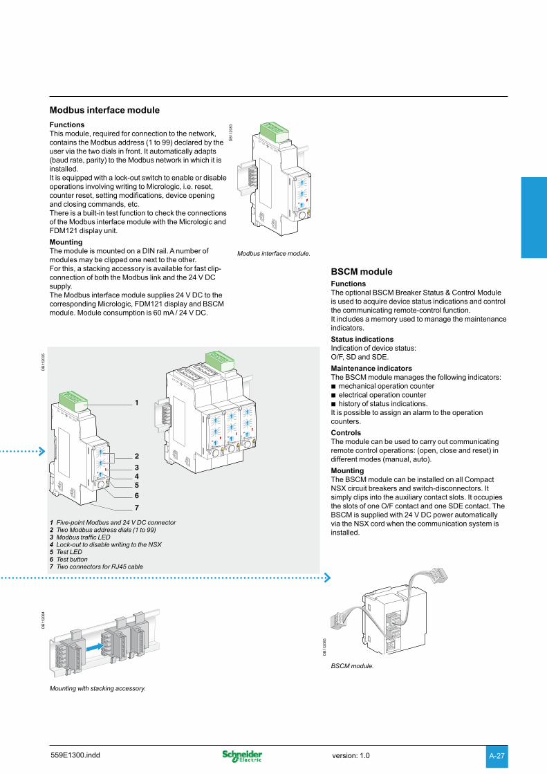
Modbus interface module
Functions
This module, required for connection to the network,
contains the Modbus address (1 to 99) declared by the
user via the two dials in front. It automatically adapts
(baud rate, parity) to the Modbus network in which it is
installed.
It is equipped with a lock-out switch to enable or disable
operations involving writing to Micrologic, i.e. reset,
counter reset, setting modifications, device opening
and closing commands, etc.
There is a built-in test function to check the connections
of the Modbus interface module with the Micrologic and
FDM121 display unit.
Mounting
The module is mounted on a DIN rail. A number of
modules may be clipped one next to the other.
For this, a stacking accessory is available for fast clip-
connection of both the Modbus link and the 24 V DC
supply.
The Modbus interface module supplies 24 V DC to the
corresponding Micrologic, FDM121 display and BSCM
module. Module consumption is 60 mA / 24 V DC.
BSCM module
Functions
The optional BSCM Breaker Status & Control Module
is used to acquire device status indications and control
the communicating remote-control function.
It includes a memory used to manage the maintenance
indicators.
Status indications
Indication of device status:
O/F, SD and SDE.
Maintenance indicators
The BSCM module manages the following indicators:
mechanical operation counter belectrical operation counter bhistory of status indications. b
It is possible to assign an alarm to the operation
counters.
Controls
The module can be used to carry out communicating
remote control operations: (open, close and reset) in
different modes (manual, auto).
Mounting
The BSCM module can be installed on all Compact
NSX circuit breakers and switch-disconnectors. It
simply clips into the auxiliary contact slots. It occupies
the slots of one O/F contact and one SDE contact. The
BSCM is supplied with 24 V DC power automatically
via the NSX cord when the communication system is
installed.
DB
112035
DB
112083
Modbus interface module.
DB
112084
Mounting with stacking accessory.
DB
112085
BSCM module.
1 Five-point Modbus and 24 V DC connector2 Two Modbus address dials (1 to 99)3 Modbus traffic LED4 Lock-out to disable writing to the NSX5 Test LED6 Test button7 Two connectors for RJ45 cable
559E1300.indd version: 1.0
A-28
Functions and characteristics
Compact NSX communication Networks and software
DB
115569
Firewall
Internet
Automatic
notification
Nomad
mode
Site Intranet
MPS100
Modbus Modbus
EGX400
Ethernet (TCP/IP/Modbus)
Consultation
RSU
RCU
Consultation
RSU
RCU
FDM121
Masterpact Compact NSX
Modbus
PowerLogic
Power MeterSepam
Compact NSX uses the Modbus
communication protocol, compatible with
SMS PowerLogic supervision systems.
Two downloadable utilities facilitate
implementation of communication functions.
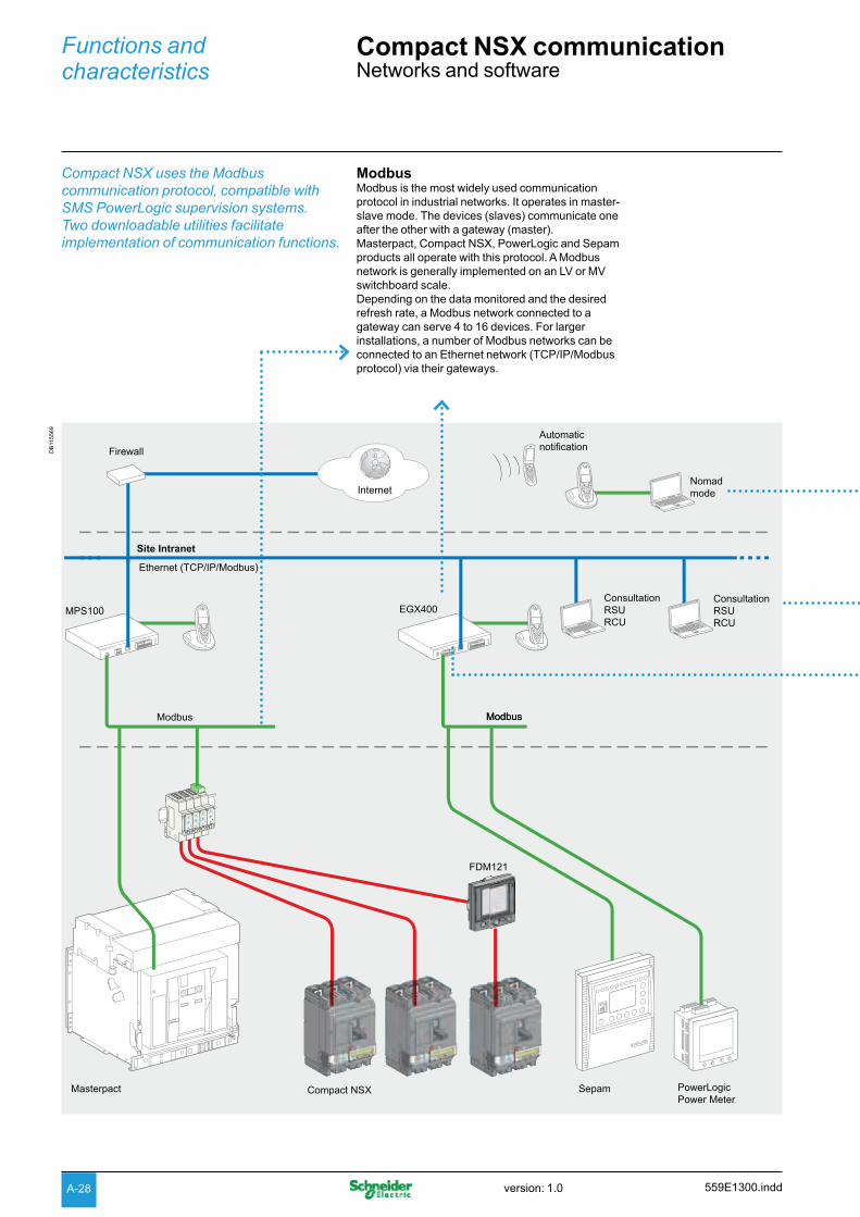
ModbusModbus is the most widely used communication
protocol in industrial networks. It operates in master-
slave mode. The devices (slaves) communicate one
after the other with a gateway (master).
Masterpact, Compact NSX, PowerLogic and Sepam
products all operate with this protocol. A Modbus
network is generally implemented on an LV or MV
switchboard scale.
Depending on the data monitored and the desired
refresh rate, a Modbus network connected to a
gateway can serve 4 to 16 devices. For larger
installations, a number of Modbus networks can be
connected to an Ethernet network (TCP/IP/Modbus
protocol) via their gateways.
559E1300.inddversion: 1.0
A-29
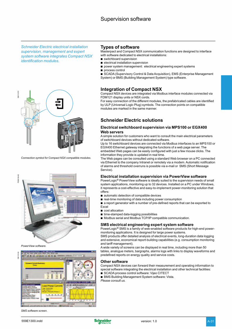
GatewayThe gateway has two functions:
access to the company intranet (Ethernet) by bconverting Modbus frames to the TCP/IP/Modbus
protocol
optional web-page server for the information from bthe devices.
Examples include MPS100, EGX400 and EGX100.
MPS100
Plug and play device. It comes loaded with a web- bpage application for graphic display of currents and
voltages and viewing of circuit-breaker status and
power and energy values.
To use the application, simply declare the Modbus
addresses of the connected slaves. Automatically
recognised devices include all Masterpact and
Compact NSX Micrologic trip units and the
PM500/700/800 and PM9c power monitoring units.
Can be used for automatic alarm notification via a bmessaging server available on the site intranet or via
mobile phones (e-mail converted into SMS).
Can be used for logging of data that can be bautomatically sent as e-mail attachments, e.g. a weekly
consumption report.
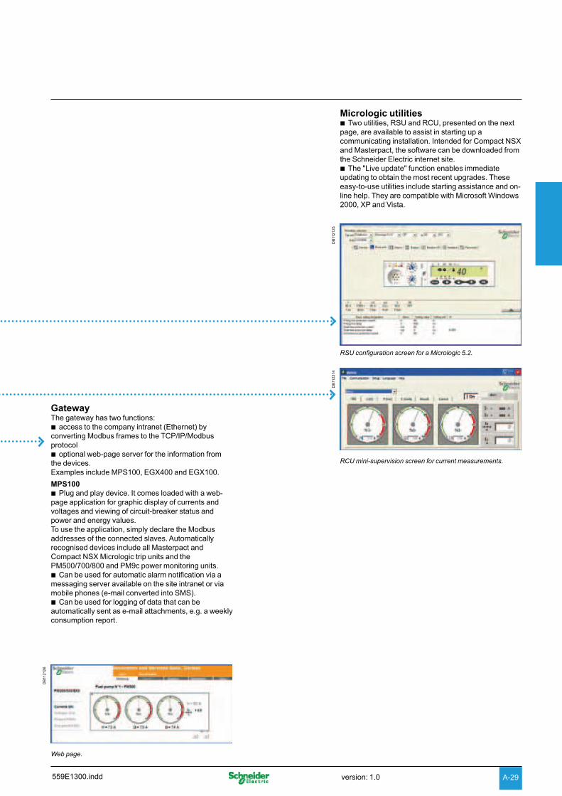
Micrologic utilitiesTwo utilities, RSU and RCU, presented on the next b
page, are available to assist in starting up a
communicating installation. Intended for Compact NSX
and Masterpact, the software can be downloaded from
the Schneider Electric internet site.
The "Live update" function enables immediate bupdating to obtain the most recent upgrades. These
easy-to-use utilities include starting assistance and on-
line help. They are compatible with Microsoft Windows
2000, XP and Vista.
DB
112125
RSU configuration screen for a Micrologic 5.2.
DB
112214
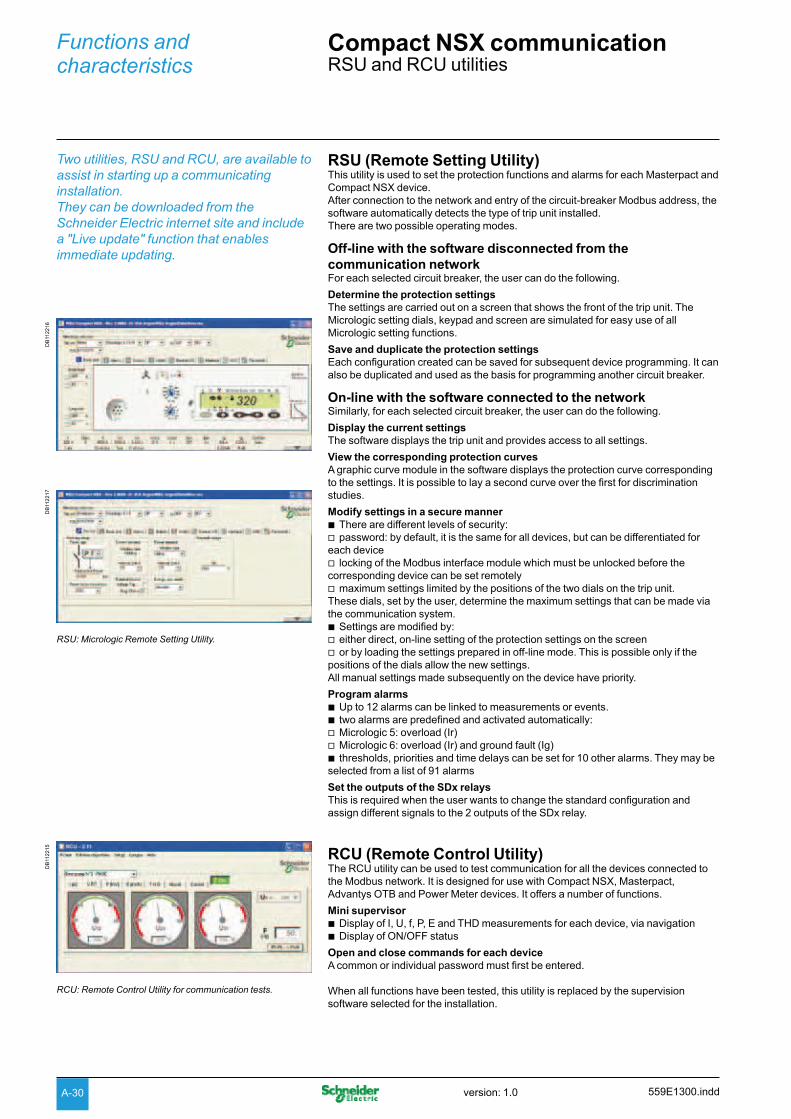
RCU mini-supervision screen for current measurements.
DB
112126
Web page.
559E1300.indd version: 1.0
A-30
Functions and characteristics
Compact NSX communication RSU and RCU utilities
RSU (Remote Setting Utility)This utility is used to set the protection functions and alarms for each Masterpact and
Compact NSX device.
After connection to the network and entry of the circuit-breaker Modbus address, the
software automatically detects the type of trip unit installed.
There are two possible operating modes.
Off-line with the software disconnected from the
communication network For each selected circuit breaker, the user can do the following.
Determine the protection settings
The settings are carried out on a screen that shows the front of the trip unit. The
Micrologic setting dials, keypad and screen are simulated for easy use of all
Micrologic setting functions.
Save and duplicate the protection settings
Each configuration created can be saved for subsequent device programming. It can
also be duplicated and used as the basis for programming another circuit breaker.
On-line with the software connected to the networkSimilarly, for each selected circuit breaker, the user can do the following.
Display the current settings
The software displays the trip unit and provides access to all settings.
View the corresponding protection curves
A graphic curve module in the software displays the protection curve corresponding
to the settings. It is possible to lay a second curve over the first for discrimination
studies.
Modify settings in a secure manner
There are different levels of security: bpassword: by default, it is the same for all devices, but can be differentiated for v
each device
locking of the Modbus interface module which must be unlocked before the vcorresponding device can be set remotely
maximum settings limited by the positions of the two dials on the trip unit. vThese dials, set by the user, determine the maximum settings that can be made via
the communication system.
Settings are modified by: beither direct, on-line setting of the protection settings on the screen vor by loading the settings prepared in off-line mode. This is possible only if the v
positions of the dials allow the new settings.
All manual settings made subsequently on the device have priority.
Program alarms
Up to 12 alarms can be linked to measurements or events. btwo alarms are predefined and activated automatically: bMicrologic 5: overload (Ir) vMicrologic 6: overload (Ir) and ground fault (Ig) vthresholds, priorities and time delays can be set for 10 other alarms. They may be b
selected from a list of 91 alarms
Set the outputs of the SDx relays
This is required when the user wants to change the standard configuration and
assign different signals to the 2 outputs of the SDx relay.
RCU (Remote Control Utility)The RCU utility can be used to test communication for all the devices connected to
the Modbus network. It is designed for use with Compact NSX, Masterpact,
Advantys OTB and Power Meter devices. It offers a number of functions.
Mini supervisor
Display of I, U, f, P, E and THD measurements for each device, via navigation bDisplay of ON/OFF status b
Open and close commands for each device
A common or individual password must first be entered.
When all functions have been tested, this utility is replaced by the supervision
software selected for the installation.
Two utilities, RSU and RCU, are available to
assist in starting up a communicating
installation.
They can be downloaded from the
Schneider Electric internet site and include
a "Live update" function that enables
immediate updating.
DB
112216
DB
112217
RSU: Micrologic Remote Setting Utility.
DB
112215
RCU: Remote Control Utility for communication tests.
559E1300.inddversion: 1.0
A-31
Types of softwareMasterpact and Compact NSX communication functions are designed to interface
with software dedicated to electrical installations:
switchboard supervision belectrical installation supervision bpower system management: electrical engineering expert systems bprocess control bSCADA (Supervisory Control & Data Acquisition), EMS (Enterprise Management b
System) or BMS (Building Management System) type software.
Integration of Compact NSXCompact NSX devices are integrated via Modbus interface modules connected via
FDM121 display units or NSX cords.
For easy connection of the different modules, the prefabricated cables are identified
by ULP (Universal Logic Plug) symbols. The connection points on compatible
modules are marked in the same manner.
Schneider Electric solutions
Electrical switchboard supervision via MPS100 or EGX400
Web serversA simple solution for customers who want to consult the main electrical parameters
of switchboard devices without dedicated software.
Up to 16 switchboard devices are connected via Modbus interfaces to an MPS100 or
EGX400 Ethernet gateway integrating the functions of a web page server. The
embedded Web pages can be easily configured with just a few mouse clicks. The
information they provide is updated in real time.
The Web pages can be consulted using a standard Web browser on a PC connected
via Ethernet to the company Intranet or remotely via a modem. Automatic notification
of alarms and threshold overruns is possible via e-mail or SMS (Short Message
Service).
Electrical installation supervision via PowerView softwarePowerLogic® PowerView software is ideally suited to the supervision needs of small
system applications, monitoring up to 32 devices. Installed on a PC under Windows,
it represents a cost-effective and easy-to-implement power-monitoring solution that
offers:
automatic detection of compatible devices breal-time monitoring of data including power consumption ba report generator with a number of pre-defined reports that can be exported to b
Excel
cost allocation btime-stamped data-logging possibilities bModbus serial and Modbus TCP/IP compatible communication. b
SMS electrical engineering expert system softwarePowerLogic® SMS is a family of web-enabled software products for high-end power-
monitoring applications. It is designed for large power systems.
SMS products offer detailed analysis of electrical events, long-duration data logging
and extensive, economical report-building capabilities (e.g. consumption monitoring
and tariff management).
A wide variety of screens can be displayed in real time, including more than 50
tables, analogue meters, bargraphs, alarms logs with links to display waveforms and
predefined reports on energy quality and service costs.
Other software Compact NSX devices can forward their measurement and operating information to
special software integrating the electrical installation and other technical facilities:
SCADA process control software: Vijeo CITECT bBMS Building Management System software: Vista. b
Please consult us.
PE
86106-6
2
PowerView software.
DB
112145
SMS software screen.
Supervision software
Schneider Electric electrical installation
supervision, management and expert
system software integrates Compact NSX
identification modules.
DB
111370
Connection symbol for Compact NSX compatible modules.
559E1300.indd version: 1.0
Functions and characteristics
Accessories for Micrologic trip units
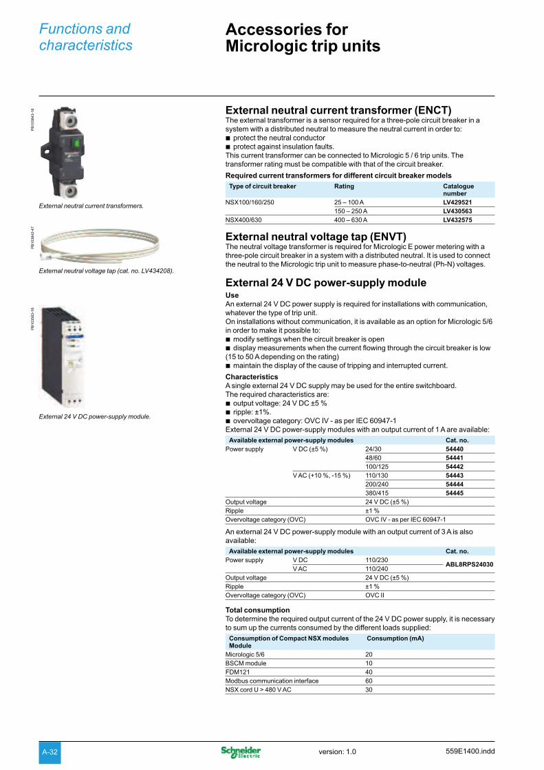
External neutral current transformer (ENCT)The external transformer is a sensor required for a three-pole circuit breaker in a
system with a distributed neutral to measure the neutral current in order to:
protect the neutral conductor bprotect against insulation faults. b
This current transformer can be connected to Micrologic 5 / 6 trip units. The
transformer rating must be compatible with that of the circuit breaker.
Required current transformers for different circuit breaker models
Type of circuit breaker Rating Catalogue number
NSX100/160/250 25 – 100 A LV429521
150 – 250 A LV430563
NSX400/630 400 – 630 A LV432575
External neutral voltage tap (ENVT)The neutral voltage transformer is required for Micrologic E power metering with a
three-pole circuit breaker in a system with a distributed neutral. It is used to connect
the neutral to the Micrologic trip unit to measure phase-to-neutral (Ph-N) voltages.
External 24 V DC power-supply moduleUse
An external 24 V DC power supply is required for installations with communication,
whatever the type of trip unit.
On installations without communication, it is available as an option for Micrologic 5/6
in order to make it possible to:
modify settings when the circuit breaker is open bdisplay measurements when the current flowing through the circuit breaker is low b
(15 to 50 A depending on the rating)
maintain the display of the cause of tripping and interrupted current. b
Characteristics
A single external 24 V DC supply may be used for the entire switchboard.
The required characteristics are:
output voltage: 24 V DC ±5 % bripple: ±1%. bovervoltage category: OVC IV - as per IEC 60947-1 b
External 24 V DC power-supply modules with an output current of 1 A are available:
Available external power-supply modules Cat. no.
Power supply V DC (±5 %) 24/30 54440
48/60 54441
100/125 54442
V AC (+10 %, -15 %) 110/130 54443
200/240 54444
380/415 54445
Output voltage 24 V DC (±5 %)
Ripple ±1 %
Overvoltage category (OVC) OVC IV - as per IEC 60947-1
An external 24 V DC power-supply module with an output current of 3 A is also
available:
Available external power-supply modules Cat. no.
Power supply V DC 110/230ABL8RPS24030
V AC 110/240
Output voltage 24 V DC (±5 %)
Ripple ±1 %
Overvoltage category (OVC) OVC II
Total consumption
To determine the required output current of the 24 V DC power supply, it is necessary
to sum up the currents consumed by the different loads supplied:
Consumption of Compact NSX modules Module
Consumption (mA)
Micrologic 5/6 20
BSCM module 10
FDM121 40
Modbus communication interface 60
NSX cord U > 480 V AC 30
PB
103843-1
8
External neutral current transformers.
PB
103583-1
8
External 24 V DC power-supply module.
PB
103842-4
7
External neutral voltage tap (cat. no. LV434208).
559E1400.inddversion: 1.0A-32
DB
115570
USB or Bluetooth link
Test connector
Display
110/240 V
TEST
30
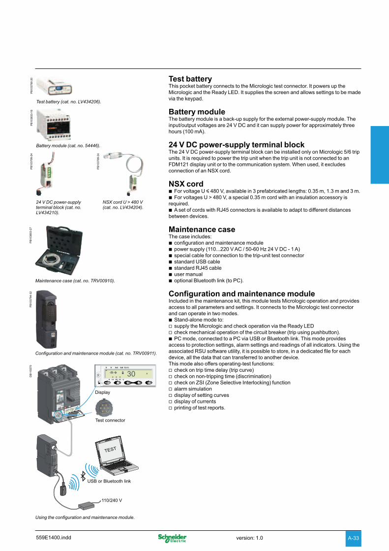
Using the configuration and maintenance module.
PB
103790-2
0
Test battery (cat. no. LV434206).
PB
103833-1
8
Battery module (cat. no. 54446).
PB
103799-2
4
PB
103789-2
4
24 V DC power-supply terminal block (cat. no. LV434210).
NSX cord U > 480 V (cat. no. LV434204).
PB
103803-2
7
Maintenance case (cat. no. TRV00910).
PB
103794-3
2
Configuration and maintenance module (cat. no. TRV00911).
Test batteryThis pocket battery connects to the Micrologic test connector. It powers up the
Micrologic and the Ready LED. It supplies the screen and allows settings to be made
via the keypad.
Battery moduleThe battery module is a back-up supply for the external power-supply module. The
input/output voltages are 24 V DC and it can supply power for approximately three
hours (100 mA).
24 V DC power-supply terminal blockThe 24 V DC power-supply terminal block can be installed only on Micrologic 5/6 trip
units. It is required to power the trip unit when the trip unit is not connected to an
FDM121 display unit or to the communication system. When used, it excludes
connection of an NSX cord.
NSX cordFor voltage U b y 480 V, available in 3 prefabricated lengths: 0.35 m, 1.3 m and 3 m.
For voltages U > 480 V, a special 0.35 m cord with an insulation accessory is brequired.
A set of cords with RJ45 connectors is available to adapt to different distances bbetween devices.
Maintenance case The case includes:
configuration and maintenance module bpower supply (110...220 V AC / 50-60 Hz 24 V DC - 1 A) bspecial cable for connection to the trip-unit test connector bstandard USB cable bstandard RJ45 cable buser manual boptional Bluetooth link (to PC). b
Configuration and maintenance moduleIncluded in the maintenance kit, this module tests Micrologic operation and provides
access to all parameters and settings. It connects to the Micrologic test connector
and can operate in two modes.
Stand-alone mode to: bsupply the Micrologic and check operation via the Ready LED vcheck mechanical operation of the circuit breaker (trip using pushbutton). vPC mode, connected to a PC via USB or Bluetooth link. This mode provides b
access to protection settings, alarm settings and readings of all indicators. Using the
associated RSU software utility, it is possible to store, in a dedicated file for each
device, all the data that can transferred to another device.
This mode also offers operating-test functions:
check on trip time delay (trip curve) vcheck on non-tripping time (discrimination) vcheck on ZSI (Zone Selective Interlocking) function valarm simulation vdisplay of setting curves vdisplay of currents vprinting of test reports. v
559E1400.indd version: 1.0 A-33
Functions and characteristics
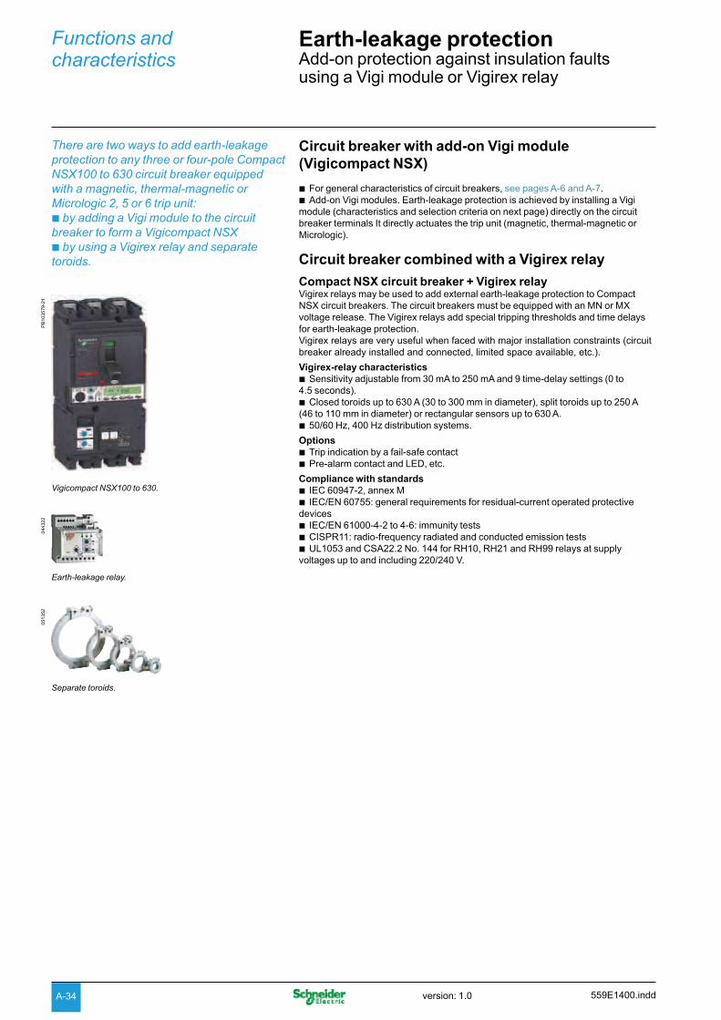
Earth-leakage protectionAdd-on protection against insulation faults using a Vigi module or Vigirex relay
There are two ways to add earth-leakage
protection to any three or four-pole Compact
NSX100 to 630 circuit breaker equipped
with a magnetic, thermal-magnetic or
Micrologic 2, 5 or 6 trip unit:
b by adding a Vigi module to the circuit
breaker to form a Vigicompact NSX
b by using a Vigirex relay and separate
toroids.
Circuit breaker with add-on Vigi module
(Vigicompact NSX)
For general characteristics of circuit breakers, b see pages A-6 and A-7.
Add-on Vigi modules. Earth-leakage protection is achieved by installing a Vigi bmodule (characteristics and selection criteria on next page) directly on the circuit
breaker terminals It directly actuates the trip unit (magnetic, thermal-magnetic or
Micrologic).
Circuit breaker combined with a Vigirex relay
Compact NSX circuit breaker + Vigirex relayVigirex relays may be used to add external earth-leakage protection to Compact
NSX circuit breakers. The circuit breakers must be equipped with an MN or MX
voltage release. The Vigirex relays add special tripping thresholds and time delays
for earth-leakage protection.
Vigirex relays are very useful when faced with major installation constraints (circuit
breaker already installed and connected, limited space available, etc.).
Vigirex-relay characteristics
Sensitivity adjustable from 30 mA to 250 mA and 9 time-delay settings (0 to b4.5 seconds).
Closed toroids up to 630 A (30 to 300 mm in diameter), split toroids up to 250 A b(46 to 110 mm in diameter) or rectangular sensors up to 630 A.
50/60 Hz, 400 Hz distribution systems. b
Options
Trip indication by a fail-safe contact bPre-alarm contact and LED, etc. b
Compliance with standards
IEC 60947-2, annex M bIEC/EN 60755: general requirements for residual-current operated protective b
devices
IEC/EN 61000-4-2 to 4-6: immunity tests bCISPR11: radio-frequency radiated and conducted emission tests bUL1053 and CSA22.2 No. 144 for RH10, RH21 and RH99 relays at supply b
voltages up to and including 220/240 V.
044322
Earth-leakage relay.
051352
Separate toroids.
PB
103579-2
1
Vigicompact NSX100 to 630.
559E1400.inddversion: 1.0A-34
PB
103579-2
1 Vigicompact NSX100 to 630 circuit breakers with
earth-leakage protectionAddition of the Vigi module does not alter circuit-breaker characteristics:
compliance with standards bdegree of protection, class II front-face insulation bpositive contact indication belectrical characteristics btrip-unit characteristics binstallation and connection modes bindication, measurement and control auxiliaries binstallation and connection accessories. b
Dimensions and weights NSX100/160/250 NSX400/630
Dimensions 3 poles 105 x 236 x 86 135 x 355 x 110
W x H x D (mm) 4 poles 140 x 236 x 86 180 x 355 x 110
Weight (kg) 3 poles 2.5 8.8
4 poles 3.2 10.8
Vigi earth-leakage protection modulesCompliance with standards
IEC 60947-2, annex B. bDecree dated 14 November 1988 (for France). bIEC 60755, class A, immunity to DC components up to 6 mA boperation down to -25 °C as per VDE 664. b
Remote indications
Vigi modules may be equipped with an auxiliary contact (SDV) to remotely signal
tripping due to an earth fault.
Use of 4-pole Vigi module with a 3-pole Compact NSX
In a 3-phase installation with an uninterrupted neutral, an accessory makes it
possible to use a 4-pole Vigi module with connection of the neutral cable.
Power supply
Vigi modules are self-supplied internally by the distribution-system voltage and
therefore do not require any external source. They continue to function even when
supplied by only two phases.
Vigi module selection
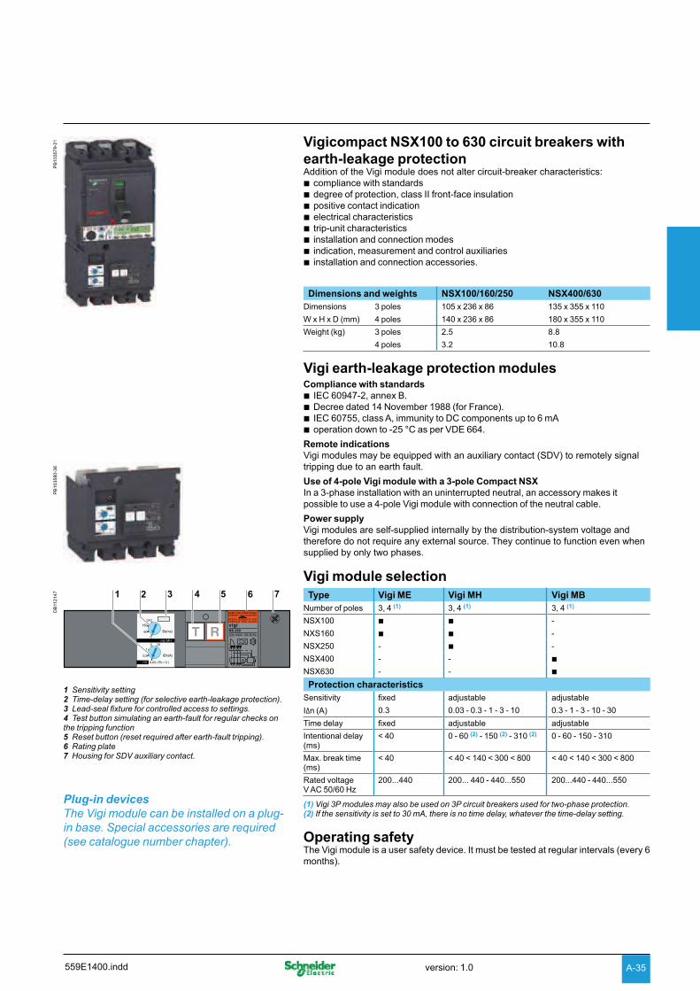
DB
112147
1 2 3 4 5 6 7
1 Sensitivity setting2 Time-delay setting (for selective earth-leakage protection).3 Lead-seal fixture for controlled access to settings.4 Test button simulating an earth-fault for regular checks on the tripping function5 Reset button (reset required after earth-fault tripping).6 Rating plate7 Housing for SDV auxiliary contact.
Plug-in devices
The Vigi module can be installed on a plug-
in base. Special accessories are required
(see catalogue number chapter).
Type Vigi ME Vigi MH Vigi MB
Number of poles 3, 4 (1) 3, 4 (1) 3, 4 (1)
NSX100 b b -
NXS160 b b -
NSX250 - b -
NSX400 - - b
NSX630 - - b
Protection characteristics
Sensitivity fixed adjustable adjustable
I n (A) 0.3 0.03 - 0.3 - 1 - 3 - 10 0.3 - 1 - 3 - 10 - 30
Time delay fixed adjustable adjustable
Intentional delay (ms)
< 40 0 - 60 (2) - 150 (2) - 310 (2) 0 - 60 - 150 - 310
Max. break time (ms)
< 40 < 40 < 140 < 300 < 800 < 40 < 140 < 300 < 800
Rated voltage V AC 50/60 Hz
200...440 200... 440 - 440...550 200...440 - 440...550
(1) Vigi 3P modules may also be used on 3P circuit breakers used for two-phase protection.(2) If the sensitivity is set to 30 mA, there is no time delay, whatever the time-delay setting.
Operating safetyThe Vigi module is a user safety device. It must be tested at regular intervals (every 6
months).
PB
103580-3
6
559E1400.indd version: 1.0 A-35