
Functional safety for SITRANS P, series DS III PROFIsafe · Abbreviations/Acronyms B SITRANS...
30
Introduction 1 General safety instructions 2 Device-specific safety instructions 3 Appendix A List of Abbreviations/Acronyms B SITRANS Pressure transmitter Functional safety for SITRANS P, series DS III PROFIsafe Product information 07/2006 A5E00849297-01 Supplement to the Operating Instructions
Transcript of Functional safety for SITRANS P, series DS III PROFIsafe · Abbreviations/Acronyms B SITRANS...

Introduction 1
General safety instructions 2
Device-specific safety instructions
3
Appendix A
List of Abbreviations/Acronyms
B
SITRANS
Pressure transmitter Functional safety for SITRANS P, series DS III PROFIsafe
Product information
07/2006 A5E00849297-01
Supplement to the Operating Instructions

Safety Guidelines This manual contains notices you have to observe in order to ensure your personal safety, as well as to prevent damage to property. The notices referring to your personal safety are highlighted in the manual by a safety alert symbol, notices referring only to property damage have no safety alert symbol. These notices shown below are graded according to the degree of danger.
Danger
indicates that death or severe personal injury will result if proper precautions are not taken.
Warning
indicates that death or severe personal injury may result if proper precautions are not taken.
Caution
with a safety alert symbol, indicates that minor personal injury can result if proper precautions are not taken.
Caution
without a safety alert symbol, indicates that property damage can result if proper precautions are not taken.
Notice
indicates that an unintended result or situation can occur if the corresponding information is not taken into account.
If more than one degree of danger is present, the warning notice representing the highest degree of danger will be used. A notice warning of injury to persons with a safety alert symbol may also include a warning relating to property damage.
Qualified Personnel The device/system may only be set up and used in conjunction with this documentation. Commissioning and operation of a device/system may only be performed by qualified personnel. Within the context of the safety notes in this documentation qualified persons are defined as persons who are authorized to commission, ground and label devices, systems and circuits in accordance with established safety practices and standards.
Prescribed Usage Note the following:
Warning
This device may only be used for the applications described in the catalog or the technical description and only in connection with devices or components from other manufacturers which have been approved or recommended by Siemens. Correct, reliable operation of the product requires proper transport, storage, positioning and assembly as well as careful operation and maintenance.
Trademarks All names identified by ® are registered trademarks of the Siemens AG. The remaining trademarks in this publication may be trademarks whose use by third parties for their own purposes could violate the rights of the owner.
Disclaimer of Liability We have reviewed the contents of this publication to ensure consistency with the hardware and software described. Since variance cannot be precluded entirely, we cannot guarantee full consistency. However, the information in this publication is reviewed regularly and any necessary corrections are included in subsequent editions.
Siemens AG Automation and Drives Postfach 48 48 90437 NÜRNBERG GERMANY
Order No.: A5E00849297-01 Edition 08/2006
Copyright © Siemens AG 2006. Technical data subject to change
Functional safety for SITRANS P, series DS III PROFIsafe Product information, 07/2006, A5E00849297-01 iii
Table of contents 1 Introduction............................................................................................................................................. 1-1
1.1 Purpose of this document .......................................................................................................... 1-1 1.2 Scope of this document ............................................................................................................. 1-1 1.3 History ........................................................................................................................................ 1-1 1.4 Further information..................................................................................................................... 1-2
2 General safety instructions ..................................................................................................................... 2-1 2.1 Safety-instrumented system ...................................................................................................... 2-1 2.2 Safety Integrity Level (SIL)......................................................................................................... 2-2
3 Device-specific safety instructions .......................................................................................................... 3-1 3.1 Application range ....................................................................................................................... 3-1 3.2 Safety function ........................................................................................................................... 3-2 3.3 Settings ...................................................................................................................................... 3-3 3.4 Behavior in case of faults........................................................................................................... 3-4 3.5 Maintenance/Checking .............................................................................................................. 3-4 3.6 Safety characteristics................................................................................................................. 3-5
A Appendix.................................................................................................................................................A-1 A.1 Literature and standards ............................................................................................................A-1 A.2 SIL Declaration of Conformity ....................................................................................................A-2 A.3 Test report (excerpt) ..................................................................................................................A-5
B List of Abbreviations/Acronyms...............................................................................................................B-1 B.1 Abbreviations .............................................................................................................................B-1
Glossary ..................................................................................................................................... Glossary-1 Index................................................................................................................................................ Index-1
Tables
Table 2-1 Safety Integrity Level ................................................................................................................. 2-3

Table of contents
Functional safety for SITRANS P, series DS III PROFIsafe iv Product information, 07/2006, A5E00849297-01

Functional safety for SITRANS P, series DS III PROFIsafe Product information, 07/2006, A5E00849297-01 1-1
Introduction 11.1 Purpose of this document
This document contains information and safety notes that you will require when using the pressure transmitter in safety-instrumented systems. It is aimed at persons who install the device mechanically, connect it electrically, parameterize and commission it, as well as at service and maintenance engineers.
1.2 Scope of this document This document deals with the pressure transmitters exclusively as a part of a safety function. This documentation is applicable only in connection with the following documentation:
No. Name Order number /1/ Operating Instructions for SITRANS P, series DS III PA A5E00053276
1.3 History This history establishes the correlation between the current documentation and the valid firmware of the device. The documentation of this edition is applicable for the following firmware:
Edition Firmware identification type
plate System integration Installation path for PDM
01 06/2006
FW: from 301.02.01K PDM V 6.0.2; DD version 01.02.01.50
SITRANS P DS III PA PROFIsafe
The most important changes in the documentation when compared with the respective previous edition are given in the following table.
Edition Remark 01 06/2006
First edition

Introduction 1.4 Further information
Functional safety for SITRANS P, series DS III PROFIsafe 1-2 Product information, 07/2006, A5E00849297-01
1.4 Further information
Information The contents of these instructions shall not become part of or modify any prior or existing agreement, commitment or legal relationship. All obligations on the part of Siemens AG are contained in the respective sales contract which also contains the complete and solely applicable warranty conditions. Any statements contained herein do not create new warranties or modify the existing warranty. The content reflects the technical status at the time of printing. We reserve the right to make technical changes in the course of further development.
Siemens Regional Offices If you need more information or have particular problems which are not covered sufficiently by the operating instructions, contact your local Siemens Regional Office. You will find the address of your local Siemens Regional Office on the Internet.
Product information on the Internet The Programming Manual forms a part of the supplied CD and is also available on the Siemens homepage on the Internet. On the supplied CD, you will also find the technical data sheet containing the ordering data, the Device Install software for SIMATIC PDM for subsequent installation and the generic station description (GSD).
See also Siemens Regional Offices (www.siemens.com/processinstrumentation/contacts) Product information on the Internet (http://www.siemens.com/sitransp) Instructions and Manuals (http://www.siemens.com/processinstrumentation/documentation)

Functional safety for SITRANS P, series DS III PROFIsafe Product information, 07/2006, A5E00849297-01 2-1
General safety instructions 22.1 Safety-instrumented system
Definition: Safety-instrumented system A safety-instrumented system executes the safety functions that are required to achieve or maintain a safe status in a system. It consists of a sensor, logic unit/control system and final controlling element. Example: A safety-instrumented system is made up of a pressure transmitter, a limit signal sensor and a control valve.
Definition: Safety function Defined function executed by a safety-instrumented system with the objective of achieving or maintaining a safe system status taking into account a defined dangerous occurrence. Example: Limit pressure monitoring
Definition: Dangerous failure Failure with the potential to bring the safety-instrumented system into a dangerous or non-functional status.
Description The sensor, logic unit/control system and final controlling element combine to form a safety-instrumented system, which executes a safety function.
Note This document deals with the SITRANS P pressure transmitter exclusively as a part of a safety function.
General safety instructions 2.2 Safety Integrity Level (SIL)
Functional safety for SITRANS P, series DS III PROFIsafe 2-2 Product information, 07/2006, A5E00849297-01
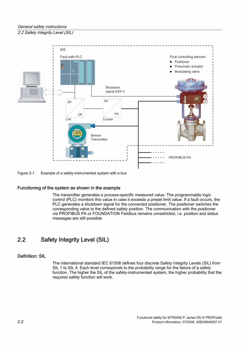
Figure 2-1 Example of a safety-instrumented system with a bus
Functioning of the system as shown in the example The transmitter generates a process-specific measured value. The programmable logic control (PLC) monitors this value in case it exceeds a preset limit value. If a fault occurs, the PLC generates a shutdown signal for the connected positioner. The positioner switches the corresponding valve to the defined safety position. The communication with the positioner via PROFIBUS PA or FOUNDATION Fieldbus remains unrestricted, i.e. position and status messages are still possible.
2.2 Safety Integrity Level (SIL)
Definition: SIL The international standard IEC 61508 defines four discrete Safety Integrity Levels (SIL) from SIL 1 to SIL 4. Each level corresponds to the probability range for the failure of a safety function. The higher the SIL of the safety-instrumented system, the higher probability that the required safety function will work.

General safety instructions 2.2 Safety Integrity Level (SIL)
Functional safety for SITRANS P, series DS III PROFIsafe Product information, 07/2006, A5E00849297-01 2-3
The achievable SIL is determined by the following safety characteristics: • Average probability of dangerous failure of a safety function in case of demand (PFDAVG) • Hardware fault tolerance (HFT) • Safe failure fractions (SFF)
Description The following table shows the dependency of the SIL on the "average probability of dangerous failures of a safety function of the entire safety-instrumented system" (PFDAVG) The table deals with "Low demand mode", i.e. the safety function is required a maximum of once per year on average.
Table 2-1 Safety Integrity Level
SIL PFDAVG 4 ≥ 10-5...< 10-4 3 ≥ 10-4...< 10-3 2 ≥ 10-3...< 10-2 1 ≥ 10-2...< 10-1
The "average probability of dangerous failures of the entire safety-instrumented system" (PFDAVG) is normally split between the three sub-systems in the following figure.
Figure 2-2 Example of PFD distribution
The following table shows the achievable Safety Integrity Level (SIL) for the entire safety-instrumented system for type B subsystems depending on the safe failure fraction (SFF) and the hardware fault tolerance (HFT). Type B subsystems include analog transmitters and shut-off valves without complex components, e.g. microprocessors (also see IEC 61508, Section 2).
HFT SFF 0 1 (0) 1) 2 (1) 1)
< 60 % Not permissible SIL 1 SIL 2 60 to 90 % SIL 1 SIL 2 SIL 3 90 to 99 % SIL 2 SIL 3 SIL 4 > 99 % SIL 3 SIL 4 SIL 4
1) As per IEC 61511-1, Section 11.4.4

General safety instructions 2.2 Safety Integrity Level (SIL)
Functional safety for SITRANS P, series DS III PROFIsafe 2-4 Product information, 07/2006, A5E00849297-01
As per IEC 61511-1, Section 11.4.4, the hardware fault tolerance (HFT) can be reduced by one (values in brackets) for sensors and final controlling elements with complex components if the following conditions are applicable for the device: • The device is ready for operation. • The user can configure only the process-related parameters, e.g. control range, signal
direction in case of a fault, limiting values, etc. • The configuration level of the firmware is blocked against unauthorized operation. • The function requires SIL of less than 4. The pressure transmitter fulfills these conditions.
See also Safety characteristics (Page 3-5)

Functional safety for SITRANS P, series DS III PROFIsafe Product information, 07/2006, A5E00849297-01 3-1
Device-specific safety instructions 33.1 Application range
Overview The pressure transmitter is available in versions like gauge pressure, differential pressure and absolute pressure. The output signal is a process-specific digital measured value. The measured value is displayed with the associated status. The pressure transmitter measures corrosive, non-corrosive and hazardous gases, vapors and liquids. You can use them for the following measurement types: • Gauge pressure • Differential pressure • Absolute pressure from the gauge pressure breaker range • Absolute pressure from the differential pressure breaker range With appropriate parameterization, you can also use it for the following additional measurement types: • Level • Volume • Mass • Flow You can install the transmitter of the appropriate version having the "intrinsically safe" type of protection EEx ia, EEx ib or "flameproof enclosure" EEx d in hazardous areas, on zone 0 and in zones 1 or 2. Devices have an EC-type examination certificate and fulfill the corresponding harmonized standards, e.g. European CENELEC.
Gauge pressure This version measures the gauge pressure of corrosive, non-corrosive and hazardous gases, vapors and liquids.
Differential pressure This version measures: • Differential pressure • Positive or negative gauge pressure • A flow rate with q ∼ , together with a throttling device It measures the pressure of corrosive, non-corrosive and hazardous gases, vapors and liquids.

Device-specific safety instructions 3.2 Safety function
Functional safety for SITRANS P, series DS III PROFIsafe 3-2 Product information, 07/2006, A5E00849297-01
Level The gauge pressure or differential pressure version measures the level of corrosive, non-corrosive and hazardous liquids with the help of appropriate parameterization. Wetted parts are made from different materials depending on the required corrosion resistance.
Flow The differential pressure version measures the flow rate of corrosive, non-corrosive and hazardous liquids with the help of appropriate parameterization. Wetted parts are made from different materials depending on the required corrosion resistance.
Absolute pressure These versions measure the absolute pressure of corrosive, non-corrosive and hazardous gases, vapors and liquids.
Requirements These pressure transmitters meet the following requirements: • Functional safety to SIL 2 under IEC 61508 or IEC 61511-1, from firmware version FW:
from 301.02.01K • Explosion protection for corresponding versions • Electromagnetic compatibility in compliance with EN 61326
3.2 Safety function
Safety function for pressure transmitters Measuring pressures is the safety function for SITRANS P. The pressure is converted to a digital measured value and transmitted by PROFIsafe communication. The measured value has an accuracy of ±2%. It is transmitted together with the status information "Validity" and "Quality". The safety function ensures that the diagnostic functions respond and signal an invalid measured value within 60 seconds in the worst case scenario.

Device-specific safety instructions 3.3 Settings
Functional safety for SITRANS P, series DS III PROFIsafe Product information, 07/2006, A5E00849297-01 3-3
Warning The binding settings and conditions are listed in the "Settings" and "Safety characteristics" sections. These conditions must be met in order to fulfill the safety function.
The calculated Mean Time Between Failures (MTBF) for the SITRANS P pressure transmitter is approximately 282 years.
See also Settings (Page 3-3) Safety characteristics (Page 3-5)
3.3 Settings The following settings must be adhered to after installing and commissioning as per the Operating Instructions:
Operation/configuration While operating/configuring, ensure that the technical data of the pressure transmitter are adhered to in their respective version.
Checking the safety function We recommend that: • You check the status for warnings and alarms. • You check the measured value limits. • Simulate various measured values and statuses. • You check the measuring accuracy that must be in the range of ± 2% for the safety
function. – You check the zero point, e.g. in a pressure-less state, for gauge and differential
pressure. – You check the zero point, e.g. with a defined pressure, for absolute pressure.
Protection against configuration changes After parameterizing/commissioning: 1. Set the lock mode in Mode 10 to write protection "L".
Operation via buttons and PROFIBUS communication is blocked. 2. Protect the keys from unintended change in the parameters, e.g. by lead-sealing.

Device-specific safety instructions 3.4 Behavior in case of faults
Functional safety for SITRANS P, series DS III PROFIsafe 3-4 Product information, 07/2006, A5E00849297-01
Reference You can find the operating instructions in the following documentation: Operating instructions SITRANS P, series DS III PA Order number A5E00053276
3.4 Behavior in case of faults
Repairs Defective devices should be sent in to the repair department with details of the fault and the cause. When ordering replacement devices, please specify the serial number of the original device. The serial number can be found on the rating plate. The address of the responsible SIEMENS repair center, contacts, spare parts lists, etc. can be found on the Internet.
See also Services & Support (http://www.siemens.com/automation/services&support) Partner (http://www.automation.siemens.com/partner)
3.5 Maintenance/Checking
Interval We recommend that the functioning of the pressure transmitter be checked at regular intervals of one year.
Checking the safety function We recommend that: • You check the status for warnings and alarms. • You check the measured value limits. • Simulate various measured values and statuses. • You check the measuring accuracy that must be in the range of ± 2% for the safety
function. – You check the zero point, e.g. in a pressure-less state, for gauge and differential
pressure. – You check the zero point, e.g. with a defined pressure, for absolute pressure.

Device-specific safety instructions 3.6 Safety characteristics
Functional safety for SITRANS P, series DS III PROFIsafe Product information, 07/2006, A5E00849297-01 3-5
Checking safety You should regularly check the safety function of the entire safety circuit in line with IEC 61508/61511. The testing intervals are determined during the calculation for each individual safety circuit in a system (PFDAVG).
Electronics The safety function of the transmitter is ensured only with the electronics delivered by the factory. It cannot be replaced.
3.6 Safety characteristics The safety characteristics necessary for using the system are listed in the "SIL declaration of conformity". These values apply under the following conditions: • The SITRANS P pressure transmitter is only used in applications with a low demand rate
for the safety function (low demand mode). • The safety-related parameters/settings have been entered by local operation or
PROFIBUS communication before commencing safety-instrumented operation. They are checked on the local display. (see "Settings" section)
• The safety function test is concluded successfully. • The transmitter is blocked against unwanted and unauthorized changes/operation. • The measured values transmitted with PROFIsafe are evaluated by a secure system. • The calculation of fault rates is based on a MTTR of 8 hours.
See also Settings (Page 3-3) SIL Declaration of Conformity (Page A-2)

Device-specific safety instructions 3.6 Safety characteristics
Functional safety for SITRANS P, series DS III PROFIsafe 3-6 Product information, 07/2006, A5E00849297-01

Functional safety for SITRANS P, series DS III PROFIsafe Product information, 07/2006, A5E00849297-01 A-1
Appendix AA.1 Literature and standards
No. Standard Description /1/ IEC 61508
Section 1-7 Functional safety of following systems: • Safety-instrumented • Electrical • Electronic • Programmable Target group: Manufacturers and suppliers of equipment
/2/ IEC 61511 Section 1-3
Functional safety - Safety systems for the process industry Target group: Planners, constructors and users

Appendix A.2 SIL Declaration of Conformity
Functional safety for SITRANS P, series DS III PROFIsafe A-2 Product information, 07/2006, A5E00849297-01
A.2 SIL Declaration of Conformity

Appendix A.2 SIL Declaration of Conformity
Functional safety for SITRANS P, series DS III PROFIsafe Product information, 07/2006, A5E00849297-01 A-3

Appendix A.2 SIL Declaration of Conformity
Functional safety for SITRANS P, series DS III PROFIsafe A-4 Product information, 07/2006, A5E00849297-01

Appendix A.3 Test report (excerpt)
Functional safety for SITRANS P, series DS III PROFIsafe Product information, 07/2006, A5E00849297-01 A-5
A.3 Test report (excerpt)

Appendix A.3 Test report (excerpt)
Functional safety for SITRANS P, series DS III PROFIsafe A-6 Product information, 07/2006, A5E00849297-01

Appendix A.3 Test report (excerpt)
Functional safety for SITRANS P, series DS III PROFIsafe Product information, 07/2006, A5E00849297-01 A-7

Appendix A.3 Test report (excerpt)
Functional safety for SITRANS P, series DS III PROFIsafe A-8 Product information, 07/2006, A5E00849297-01

Functional safety for SITRANS P, series DS III PROFIsafe Product information, 07/2006, A5E00849297-01 B-1
List of Abbreviations/Acronyms BB.1 Abbreviations Abbreviation Full term in English Meaning HFT Hardware Fault Tolerance Hardware fault tolerance:
Capability of a function unit to continue executing a required function in the presence of faults or deviations.
MTBF Mean Time Between Failures Average period between two failures MTTR Mean Time To Repair Average period between the occurrence of a fault in a device or
system and the repair PFD Probability of Failure on Demand Probability of dangerous failures of a safety function on demandPFDAVG Average Probability of Failure on
Demand Average probability of dangerous failures of a safety function on demand
SIL Safety Integrity Level The international standard IEC 61508 defines four discrete Safety Integrity Levels (SIL 1 to SIL 4). Each level corresponds to a range of probability for failure of a safety function. The higher the Safety Integrity Level of the safety-instrumented system, the lower the probability that it will not execute the required safety functions.
SFF Safe Failure Fraction Proportion of safe failures: Proportion of failures without the potential to bring the safety-instrumented system into a dangerous or non-permissible functional status.
FIT Failure in Time Frequency of failure Number of faults withing 109 hours
TI Test Interval Testing interval of the protective function Classification and description of the safety-instrumented system in terms of redundancy and the selection procedures used. "Y" Specifies how often the safety function is executed
(redundancy). "X" Determines how many channels have to work correctly.
XooY "X out of Y" voting
Example: Pressure measurement: 1oo2 architecture. A safety-instrumented system decides that a specified pressure limit has been exceeded if one out of two pressure sensors reaches this limit. In a 1oo1 architecture, there is only one pressure sensor.

List of Abbreviations/Acronyms B.1 Abbreviations
Functional safety for SITRANS P, series DS III PROFIsafe B-2 Product information, 07/2006, A5E00849297-01

Functional safety for SITRANS P, series DS III PROFIsafe Product information, 07/2006, A5E00849297-01 Glossary-1
Glossary
Dangerous failure Failure with the potential to bring the safety-instrumented system into a dangerous or non-functional status.
Fail-safe The capability of a control to maintain the safe state of the controlled device, e.g. machine, process, or to bring the device to a safe state even when faults/failures occur.
Failure/fault Failure A resource is no longer capable of executing a required function. Fault Undesired state of a resource indicated by the incapability of executing a required function.
Fault → Failure/fault
Fault tolerance Fault tolerance N means that a device can execute the intended task even when N faults exist. The device fails to execute the intended function in case of N+1 faults.
Final controlling element Converter that converts electrical signals into mechanical or other non-electrical variables.
Risk The combination of probability of a damage occurring and its magnitude.

Glossary
Functional safety for SITRANS P, series DS III PROFIsafe Glossary-2 Product information, 07/2006, A5E00849297-01
Safety function Defined function executed by a safety-instrumented system with the objective of achieving or maintaining a safe system status taking into account a defined dangerous occurrence. Example: Limit pressure monitoring
Safety Integrity Level → SIL
Safety-instrumented system A safety-instrumented system executes the safety functions that are required to achieve or maintain a safe status in a system. It consists of a sensor, logic unit/control system and final controlling element. Example: A safety-instrumented system is made up of a pressure transmitter, a limit signal sensor and a control valve.
Sensor Converter that converts mechanical or other non-electrical variables into electrical signals.
SIL The international standard IEC 61508 defines four discrete Safety Integrity Levels (SIL) from SIL 1 to SIL 4. Each level corresponds to the probability range for the failure of a safety function. The higher the SIL of the safety-instrumented system, the higher probability that the required safety function will work. The achievable SIL is determined by the following safety characteristics: • Average probability of dangerous failure of a safety function in case of demand (PFDAVG) • Hardware fault tolerance (HFT) • Safe failure fractions (SFF)

Functional safety for SITRANS P, series DS III PROFIsafe Product information, 07/2006, A5E00849297-01 Index-1
Index
C characteristics
Safety, 3-5 Checking, 3-4 Control system, 2-1
D documentation
required, 1-1
E Electronics, 3-5
F Final controlling element, 2-1
H History, 1-1
M Maintenance, 3-4 Mean Time Between Failures, 3-3
Measuring accuracy, 3-3 More information, 1-2 MTTR, 3-5
P Product information on the Internet, 1-2
S Safety
Checking, 3-5 Safety function, 2-1, 3-2
Checking, 3-3, 3-4 Sensor, 2-1 Settings, 3-3 Siemens Regional Office, 1-2 system
Safety-instrumented, 2-1
T Technical data, 3-3
W Write protection, 3-3

Index
Functional safety for SITRANS P, series DS III PROFIsafe Index-2 Product information, 07/2006, A5E00849297-01


