FUNCTIONAL INTEGRATION OF VERTICAL FLIGHT PATH AND …
21
FUNCTIONAL INTEGRATION OF VERTICAL FLIGHT PATH AND SPEED CONTROLUSING ENERGY PRINCIPLES A. A. Lambregts Boeing Commercial Airplane Company Seattle, Washington First Annual.NASA Aircraft Controls Workshop NASA Langley Research Center Hampton, Virginia October 25-27, 1983 389
Transcript of FUNCTIONAL INTEGRATION OF VERTICAL FLIGHT PATH AND …
FUNCTIONAL INTEGRATION OF VERTICAL FLIGHT PATH AND SPEED CONTROL USING ENERGY PRINCIPLES
A. A. Lambregts Boeing Commercial Airplane Company
Seattle, Washington
First Annual.NASA Aircraft Controls Workshop NASA Langley Research Center
Hampton, Virginia October 25-27, 1983
389
ABSTRACT
A generalized automatic flight control system has been developed which integrates all longitudinal flight path and speed control functions previously provided by a pitch autopilot and autothrottle. In this design, a net thrust command is computed based on total energy demand arising from both flight path and speed targets. The elevator command Is computed based on the energy distribution error between flight path and speed. The engine control is configured to produce the commanded net thrust. The design incorporates control strategies and hierarchy to deal systematically and effectively with all aircraft operational requirements, control nonlinearities, and performance limits. Consistent decoupled maneuver control is achieved for all modes and flight conditions without outer loop gain schedules, control law submodes, or control function duplication.
390

STATE-OF-ART AUTOPILOT/AUTOTHROTTLE
Virtually every automatic flight control system (AFCS) in use today has been designed using a single-input, single-output control strategy. Although the elevator control loop may be closed on either speed or flight path, the autopilot path control modes have become the most widely used. Automatic speed control using the throttles was then developed as a natural complement to the autopilot path control modes.
Unfortunately, this historic system evolution has not resulted in optimum AFCS capabilitSes and performance. For certain flight conditions, the autopilot path control at constant thrust produces speed instabilities, while autothrottle speed control at constant elevator results in path instability. Together, they can provide stable flight path and speed control. However, the operation is far from coordinated teamwork. Generally, the autopilot is designed first and satisfactory path control using the powerful elevator is often obtained at the expense of speed control. This leaves the autothrottle in a no-win situation: poor speed control with acceptable throttle activity or acceptable speed control with objectionable throttle activity.
For large autopilot path change commands, the conventional control strategy breaks down because thrust will limit, causing loss of autothrottle speed control, with the ensuing risk of stalling or overspeeding the aircraft.
----------1
I Autothrottle i
l Elevator and throttle each control one variable.
I I
r I
J+o+&q~,
L ----------
r-----------
! 1
I Elevator I b Control
Se I I
I L * I
I I I !
Airplane
1
I I .
:------------~ Autopilot 1
391

LIMITATIONS OF THE TRADITIONAL DESIGN APPROACH
The traditional single-input, single-output design approach has a number of other fundamental design limitations. Modes that have not specifically been designed to work together are generally incompatible. This has led to a proliferation of specialized control modes of limited use.
Still, pilots complain that the operation of the present generation automatic control systems is often contrary to the way the pilot uses the controls. The lack of short-term coordination of elevator and throttle commands results in undesirable and inefficient controller activity. This is especially true for the autothrottle system in energy-management-type situations.
Clearly, using the throttles to control speed is not an ideal control strategy. H. A. Soul6 summed it all up in the title of his article (ref. 1), "The Throttles Control Speed, Right? Wrong!"
In the present designs, the thrust control loop is subject to extreme variations in loop qain and dynamics due to variations in aircraft weight and engine characteristics for different conditions. Poor system robustness causes wide performance variations.
The fragmented bottom-up design approach makes it difficult to efficiently implement general design requirements, such as limiting of speeds and maneuver rates, because provisions have to be made in many places.
Research Background
Traditional Single-Input - Single-Output Design Approach Has Inherent Deficiencies:
l Each mode combination is new problem
l Performance of one mode depends on other engaged mode
l Deficiency of one mode often basis for design of another
l Lack of control coordination leads to undesirable coupling
l Control coupling limits achievable damping
l Difficult to deal effectively with performance/safety limits
l Many difficult and, iterative development programs have not resulted in fundamental design improvements
392
FUNCTIONAL OVERLAP
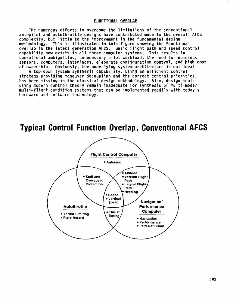
The numerous efforts to overcome the limitations of the conventional autopilot and autothrottle designs have contributed much to the overall AFCS complexity, but little to the improvement in the fundamental design methodology. This is illustrated in this figure showing the functional overlap in the latest generation AFCS. Basic flight path and speed control capability now exists in all three computer systems! This results in operational ambiguities, unnecessary pilot workload, the need for numerous sensors, computers, interfaces, elaborate configuration control, and high cost of ownership. Obviously, the underlying system architecture is not ideal.
A top-down system synthesis capability, using an efficient control strategy providing maneuver decoupling and the correct control priorities, has been missing in the classical design methodology. Also, design tools using modern control theory remain inadequate for synthesis of multi-mode/ multi-flight condition systems that can be implemented readily with today's hardware and software technology.
Typical Control Function Overlap, Conventional AFCS
/
Flight Control Computer
l Autoland
l Vertical Flight
Autothrottle Performance
l Thrust Limiting l Flare Retard
Computer
l Navigation l Performance
Y l Path Definition /
393
DESIGN OBJECTIVES FOR THE INTEGRATED SYSTEM
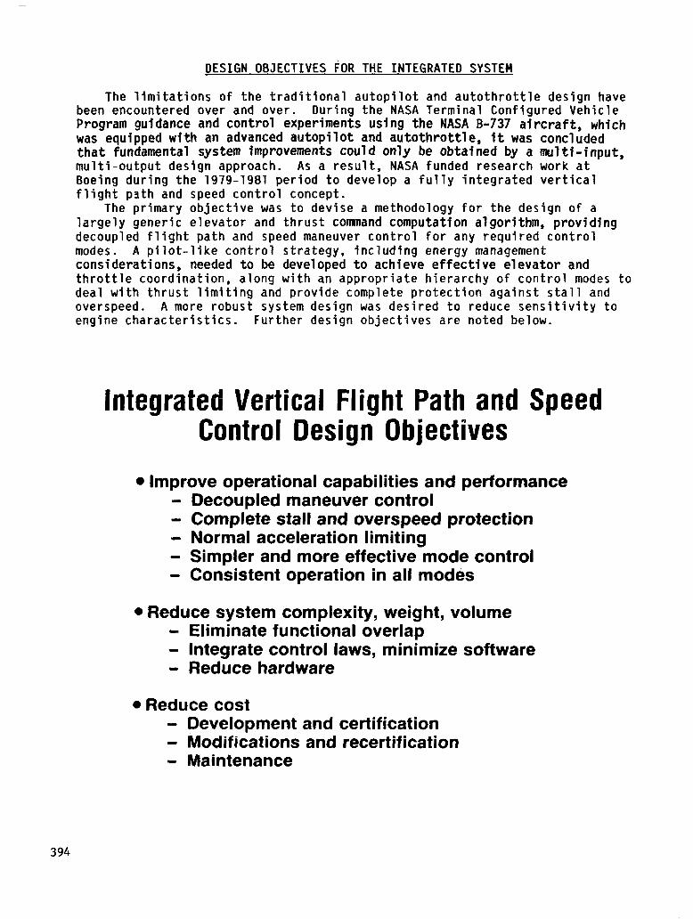
The limitations of the traditional autopilot and autothrottle design have been encountered over and over. During the NASA Terminal Configured Vehicle Program guidance and control experiments using the NASA B-737 aircraft, which was equipped with an advanced autopilot and autothrottle, it was concluded that fundamental system improvements could only be obtatned by a multi-input, multi-output design approach. As a result, NASA funded research work at Boeing during the 1979-1981 period to develop a fully integrated vertical flight path and speed control concept.
The primary objective was to devise a methodology for the design of a largely generic elevator and thrust connnand computation algorithm, providing decoupled flight path and speed maneuver control for any required control modes. A pilot-like control strategy, including energy management considerations, needed to be developed to achieve effective elevator and throttle coordination, along with an appropriate hierarchy of control modes to deal with thrust limiting and provide complete protection against stall and overspeed. A more robust system design was desired to reduce sensitivity to engine characteristics. Further design objectives are noted below.
Integrated Vertical Flight Path and Speed Control Design Objectives
l Improve operational capabilities and performance - Decoupled maneuver control - Complete stall and overspeed protection - Normal acceleration limiting - Simpler and more effective mode control - Consistent operation in all modes
l Reduce system complexity, weight, volume - Eliminate functional overlap - Integrate control laws, minimize software - Reduce hardware
l Reduce cost - Development and certification - Modifications and recertification - Maintenance
394
WGN APPROACH
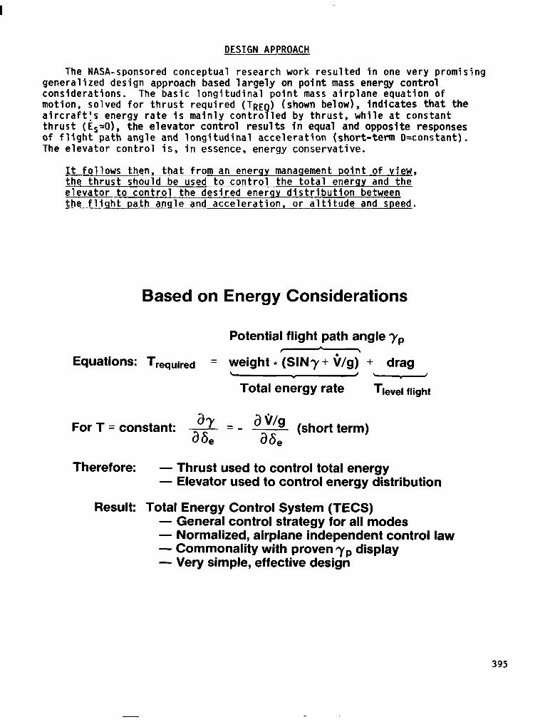
The NASA-sponsored conceptual research work resulted in one very promising generalized design approach based largely on point mass energy control considerations. The basic longitudinal point mass airplane equation of motion, solved for thrust required (TRE ) (shown below), indicates that the aircraftls energy rate is mainly contra 9 led by thrust, while at constant thrust (Es-O), the elevator control results in equal and opposite responses of flight path angle and longitudinal acceleration (short-term D-constant). The elevator control is, in essence, energy conservative.
It follows then, that from-an energy management point of view, the thrust should be used to control the total ener gy and the elevator to control the desired energy distribution between ihe flight-path angl.eeand acceleration, or altitude and speed.
Based on Energy Considerations
Potential flight path angle yr,
Equations: Trequired = weight *‘(SIN7 + V/g,’ + drag L J \ I
Total energy rate Tlevel flight
For T = constant: ay = _ a\i/g - ah a6 (short term) e
Therefore: - Thrust used to control total energy - Elevator used to control energy distribution
Result: Total Energy Control System (TECS) - General control strategy for all modes - Normalized, airplane independent control law - Commonality with proven 7yp display - Very simple, effective design
395
GENERIC TOTAL ENERGY AND ENERGY DISTRIBUTION CONTROL LAW
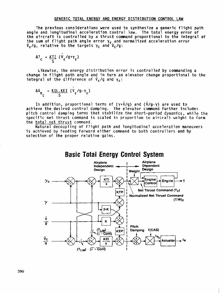
The previous considerations were used to synthesize a generic flight path angle and longitudinal acceleration control law. The total energy error of the aircraft is controlled by a thrust command proportional to the integral of the sum of flight path angle error y,.and normalized acceleration error V,/g, relative to the targets yc and Vc/g:
ATC = YTI upYE) S
Likewise, the energy distribution error is controlled by commanding a change in flight path angle and in turn an elevator change proportional to the integral of the difference of V,/g and yc:
"e C = KIL.KEI (;/g-y,)
S
In addition, proportional terms of (y+$/g) and (i/g-y) are used to achieve the desired control damping. The elevator command further includes pitch control damping terms that stabilize the short-period dynamics, while the specific net thrust command is scaled in proportion to aircraft weight to form the total net thrus.1 command.
Natural decoupling of flight path and longitudinal acceleration maneuvers is achieved by feeding forward either command to both controllers and by selection of the proper relative gains.
Basic Total Energy Control System Airplane I Airplane Independent ml- Dependent Design ! Weight Fesign
’ ’ IJ
Yc i t, ~~l~Engine~---T
, , , x 9 j \ Net Thrust Command ;;Gdjc l Normalized Net Thrust Command
Pitch Damping
(T,,,) . (; - Cont) i
396

IMPLEMENTATION OF FLIGHT PATH AND SPEED MODES
Using this generalized design approach, all needed flight path and speed control modes of the AFCS can be provided without replication of functions and with the proper hierarchy. The resulting system is called "total energy control system" (TEcS). For the outer loop flight path and speed control modes, the altitude and. speed errors are simply normalized to form the yc and Vc signals.
The control law calls for an exponential reduction of the altitude and speed errors with a time constant T inversely proportional to Kh, KV. Thus, to preserve decoupling for simultaneous altitude and speed maneuvers and to maintain the correct relative energy relationship between altitude and speed errors, Kh = KV must be chosen.
All flight path modes ultimately produce a flight path angle comand yc * All speed control modes produce a V,/g. The minimum and maximum speed limiting modes VHIN and VMAX enter downstream of all other speed modes and by autonomous engage logic provide stall and overspeed protection at all times. A more detailed system description is presented in reference 2.
TECS Architecture and Mode Hierarchy
h/g
Generalized Thrust
and Elevator
Command Computation
+Tc
397
USE OF ENERGY COMMAND RATE LIMITS
The total energy control system meets all functional, operational, and performance requirements of the overall automatic flight control system. General system requirements are met by generic design solutions, implemented at strategic points in the signal processing, so they apply to all intended modes and do not have to be replicated.
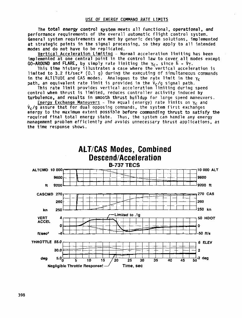
Vertical Acceleration Limiting - Normal acceleration limiting has been implemented at one central point in the control law to cover. all. modes except GO-AROUND and FLARE, by simply rate limiting the yc, since h = Vy.
This time history illustrates a case where the vertical acceleration is limited to 3.2 ft/sec2 (0.1 CJ) during the executing of simultaneous commands in the ALTITUDE and CAS modes. Analogous to the rate limit in the yc path, an equivalent rate limit is provided in the V,/g signal path.
This rate limit provides vertical acceleration limiting during s.peed control when thrust is limited, reduces controller activity induced by turbulence, and results in smooth thrust buildup for large speed maneuvers.
Enerqy Exchange Maneuvers - The equal (energy) rate limits on yc and V,/g assure that for dual opposing commands, the system first exchanges energy to the maximum extent possible before commanding thrust to satisfy the required final total energy state. Thus, the system can handle any energy management problem efficiently and avoids unnecessary thrust applications, as the time response shows.
ALTICAS Modes, Combined Descend/Acceleration
B-737 TECS ALTCMD 10 000 10 000 ALT
9600 9600
fi 9200 9200 ft
CASCMD 270 270 CAS
260 260
VERT 4 50 HDOT ACCEL
0 0
ttlsec2 -4 -50 ws
THROTTLE 55.0 6 ELEV
30.0 2
deg 5.0 -2 deg
Negligible Throttle Response! 1 Time, set
398
SPEED CONTROL PRIORITY
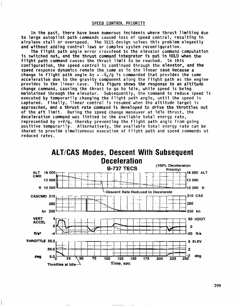
In the past, there have been numerous incidents where thrust limiting due to large autopilot path commands caused loss of speed control, resulting in airplane stall or overspeed. The TECS design solves this problem elegantly and without adding control laws or complex system reconfiguration.
The flight path angle error crossfeed to the elevator command computation is switched out, and the thrust command integrator is put in HOLD when the flight path command causes the thrust limit to be reached. In this configuration, the speed control is continued through the elevator, and the speed response dynamics remain the-same as in the linear case because a change in flight path angle Ay = -V,/g is commanded that provides the same acceleration due to the gravity component along the flight path as the engine provides in the linear case. This figure shows the response to an altitude change command, causing the thrust to go to idle, while speed is being maintained through the elevator. Subsequently, the command to reduce speed is executed by temporarily changing the flight path angle, until the speed is captured. Finally, linear control is resumed when the altitude target is approached, and a thrust rate command is developed to drive the throttles out of the aft limit. During the speed change maneuver at idle thrust, the deceleration command was limited to the available total energy rate, represented by ytV/g, thereby preventing the flight path angle from going positive temporarily. Alternatively, the available total energy rate can be shared to provide simultaneous execution of flight path and speed commands at reduced rates.
ALTXAS Modes, Descent With Subsequent
ALT 16 000 CMD
13 000
fl 10000
Deceleration B-737 TECS
(100% Deceleration Priority)
16
13
10
000 ALT
000
000 ft LDescent Rate Reduced to Decelerate
CASCMD 310 ~~ 310 . . . ..1........ . . . . . . . . . CAS .“.
280 l . . .
------ --~~~ ‘C. .- .- 280 -..
kn 250 -2250 kn
VERT 4 50 ACCEL
0 0
ftld -4 -50
HDOT
ftls
THROTTLE 55.0 8 ELEV
2
b2 deg
399
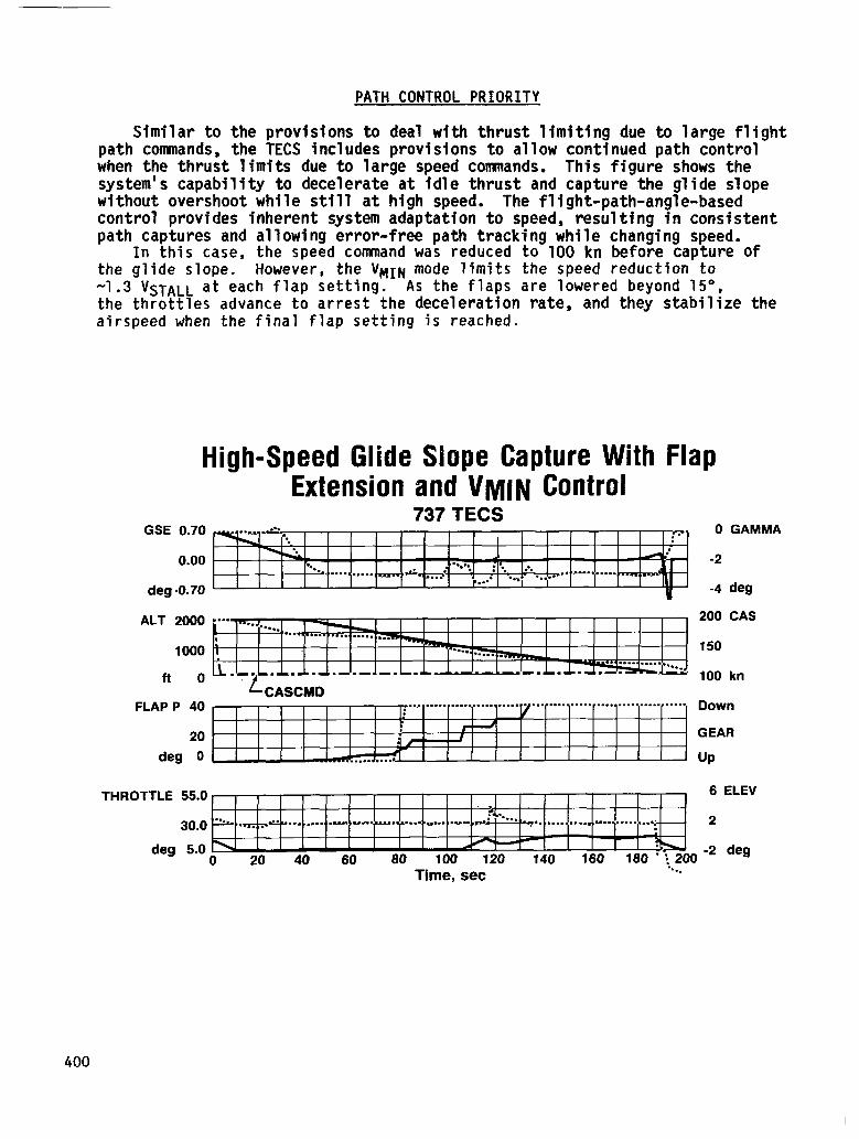
PATH CONTROL PRIORITY
Similar to the provisions to deal with thrust limiting due to large flight path commands, the TECS includes provisions to allow continued path control when the thrust limits due to large speed commands. This figure shows the system's capability to decelerate at idle thrust and capture the glide slope without overshoot while still at high speed. The flight-path-angle-based control provides inherent system adaptation to speed, resulting in consistent path captures and allowing error-free path tracking while changing speed.
In this case, the speed command was reduced to 100 kn before capture of the glide slope. However, the VMIN mode limits the speed reduction to -1.3 VSTALL at each flap setting. As the flaps are lowered beyond 15", the throttles advance to arrest the deceleration rate, and they stabilize the airspeed when the final flap setting is reached.
High-Speed Glide Slope Capture With Flap Extension and VM~N Control
737 TECS GSE 0.70
0.00
deg .0.70
ALT 2000
1000
ft 0
FLAP P 40
20
deg 0
0 GAMMA
-2
-4 deg
200 CAS
150
100 kn
Down
GEAR
UP
THROTTLE 55.0 6 ELEV
30.0 2
deg 5.0 0 20 40 60 60 100 120 140 160 180
’ :*200
-2 deg
Time, set *..
400
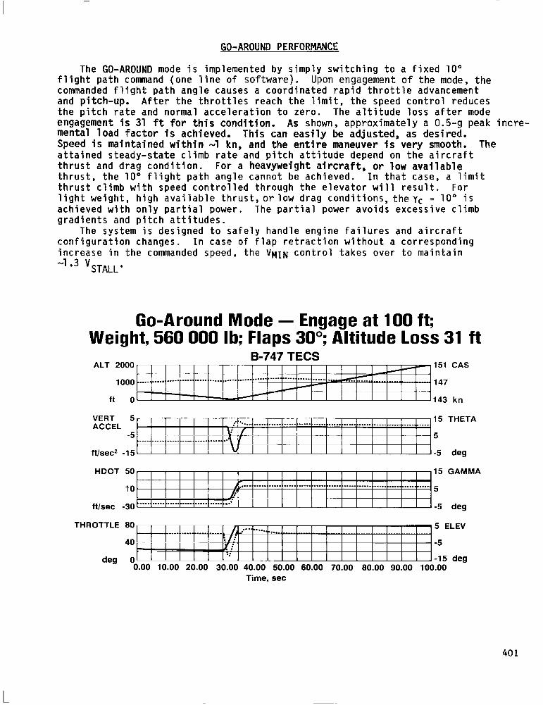
GO-AROUND PERFORMANCE
The GO-AROUND mode is implemented by simply switching to a fixed 10" flight path command (one line of software). Upon engagement of the mode, the commanded flight path angle causes a coordinated rapid throttle advancement and pitch-up. After the throttles reach the limit, the speed control reduces the pitch rate and normal acceleration to zero. The altitude loss after mode engagement is 31 ft for this condition. mental load factor is achieved.
As shown, approximately a 0.5-g peak incre- This can easily be adjusted, as desired.
Speed is maintained within -1 kn, and the entire maneuver is very smooth. The attained steady-state climb rate and pitch attitude depend on the aircraft thrust and drag condition. For a heavyweight aircraft, or low available thrust, the 10" flight path angle cannot be achieved. In that case, a limit thrust climb with speed controlled through the elevator will result. For light weight, high available thrust,orlow drag conditions, theyc = loo is achieved with only partial power. The partial power avoids excessive climb gradients and pitch attitudes.
The system is designed to safely handle engine failures and aircraft configuration changes. In case of flap retraction without a corresponding increase in the commanded speed, the VMTN control takes over to maintain
-lo3 "STALL' . .-.
Go-Around Mode - Engage at 100 ft; Weight, 560 000 lb; Flaps 30”; Altitude loss 31 ft
B-747 TECS ALT 2000
1000
ft 0
151 CAS
147
143 kn
VERT 5 15 THETA ACCEL
-5 5
ftlsec2 -15 -5 deg
HDOT 50 15 GAMMA
10 5
ftlsec -30 -5 deg
THROTTLE 80 5 ELEV
40 -5
deg 0 -15 deg 0.00 10.00 20.00 30.00 40.00 50.00 60.00 70.00 80.00 90.00 100.00
Time, set
401

COMPUTER-AUGMENTED MANUAL CONTROL
The total energy COrltrOl system is well suited for providing flight path angle based computer-augmented control because of the system's decoupled control characteristics. In this mode, also called Velocity Vector Control Wheel Steering (VCWS). a rate of change of flight path angle command (yc) proportional to the column force is developed. The column force signal is gain scheduled with l/V to provide constant stickforce per "g", and integrated to develop the flight path angle command yc. An inertial flight path angle feedback yI = h/VGROUNU iS used t0 develop the basic error Signal
yE, and provide long-term control relative to an inertial reference. This yc signal is also fed forward to the thrust and elevator comand to obtain the desired augmented response lag of y relative to yc without causing speed perturbations.
The time history shows responses tailored to yield xy = 2.5 set, the fastest response achievable with parallel servos while avoiding elevator over- control and stickforce reversal. It should be noted that this ~~ is too long for closure of the primary pilot loop using y display. To overcome this problem, the yc is displayed along with y. The yc had been shown on the NASA I3737 to be a satisfactory primary pilot display for the flight path angle CWS mode (ref. 3). This mode can be used on various transport aircraft to obtain virtually identical and optimized handling characteristics.
Velocity CWS Responses to 12-lb Column Pull/Push 6747 TECS
GAMCMD 0.10
0.00
deg -0.10
Flaps 30° Gear Down + 12 lb Pull/Push
1 GAMMA
0
-1 deg
COLUMN 20 FORCE
0
lb -20
CAS 174
170
kn 166
THROTTLE 80
40
deg 0 0 6 12 18 24 30 36
Time. set
42 48 54
8 VERT ACCEL
0
-8 ftls2
6000 ALT
5000
4000 ft
4 ELEV
0
-4 deg 60
402
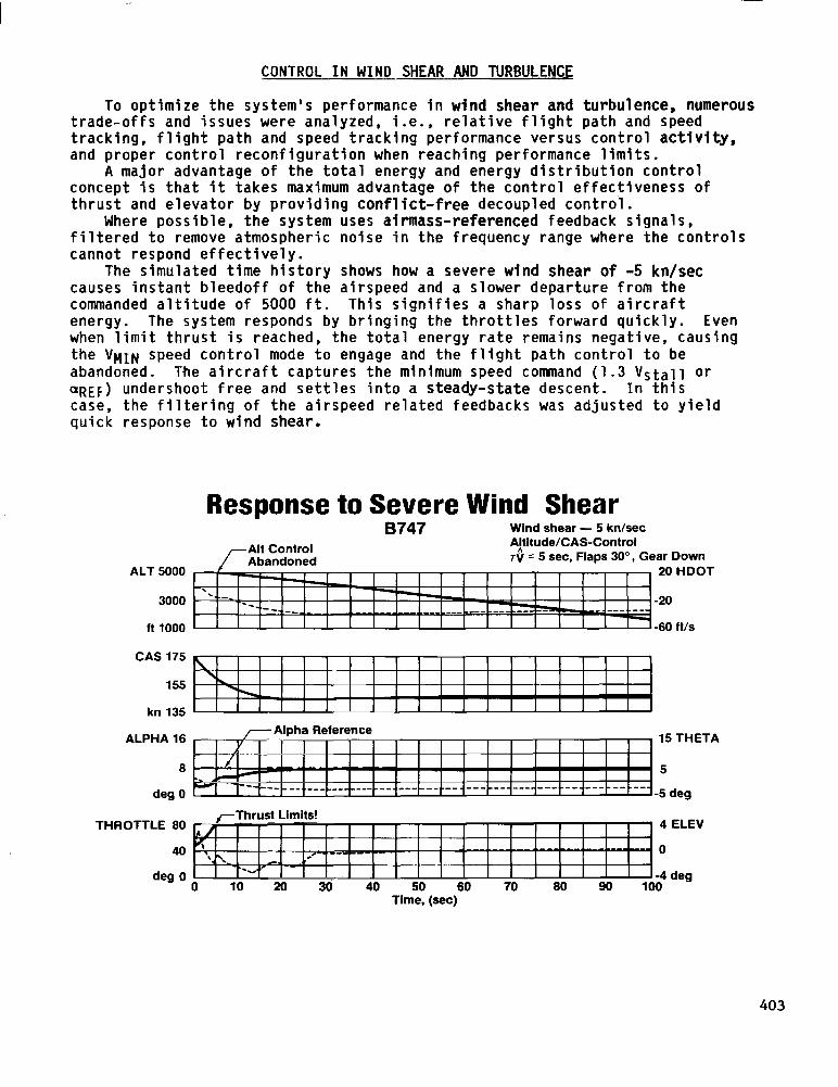
CONTROL IN WIND SHEAR AND TURBULENCE
To optimize the system's performance in wind shear and turbulence, numerous trade-offs and issues were analyzed, i.e., relative flight path and speed tracking, flight path and speed tracking performance versus control activity, and proper control reconfiguration when reaching performance limits.
A major advantage of the total energy and energy distribution control concept is that it takes maximum advantage of the control effectiveness of thrust and elevator by providing conflict-free decoupled control.
Where possible, the system uses airmass-referenced feedback signals, filtered to remove atmospheric noise in the frequency range where the controls cannot respond effectively.
The simulated time history shows how a severe wind shear of -5 kn/sec causes instant bleedoff of the airspeed and a slower departure from the commanded altitude of 5000 ft. This signifies a sharp loss of aircraft energy. The system responds by bringing the throttles forward quickly. Even when limit thrust is reached, the total energy rate remains negative, causing the VWTW speed control mode to engage and the flight path control to be abandoned. The aircraft captures the minimum speed command (1.3 Vstall or QREF) undershoot free and settles into a steady-state descent. In this case, the filtering of the airspeed related feedbacks was adjusted to yield quick response to wind shear.
Response to Severe Wind Shear B747 Wind shear - 5 kn/sec
ALT
11
ar Down 20 HDOT
60 ft/s
CAS 175
155
kn 135
ALPHA 16
8
deg 0
THROTTLE 80
40
deg 0
15 THETA
5
-5 deg
0 10 20 30 40 50 60 70 Time, (set)
ELEV
403
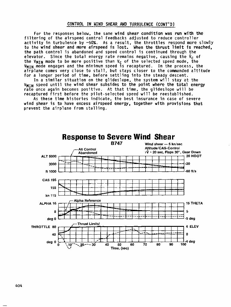
CONTROL IN WIND SHEAR AND TURBULENCE (CONT’D)
For the responses below, the same wind shear condition was run with the filtering of the airspeed control feedbacks adjusted to reduce controller activity in turbulence by -50%. As a result, the throttles respond more slowly to the wind shear and more airspeed is lost. When the thrust limit is reached, the path control is abandoned and speed control is continued through the elevator. Since the total energy rate remains negative, causing the Vc of the VMIW mode to be more positive than Vc of the selected speed mode, the VnIW mode engages and the minimum speed is recaptured. In the process, the airplane comes very close to stall, but stays closer to the commanded altitude for a longer period of time, before settling into the steady descent.
In a similar situation on the glideslope, the system will stay at the VHIN speed until the wind shear subsides to the point where the total energy rate once again becomes positive. At that time, the glideslope will be recaptured first before the pilot-.selected speed will be reestablished.
As these time histories indicate, the best insurance in case of severe wind shear is to have excess airspeed energy, together with provisions that prevent the airplane from stalling.
Response to Severe Wind Shear B747 Wind shear - 5 kn/sec
Altitude/CA!&Control ear Down
ALT 5000 20 HDOT
3000 -20
ft 1000 -60 ft/s
CAS 195
155
kn 115
ALPHA 16
8
deg 0
15 THETA
5
-5 deg
THROTTLE 80
40
deg 0 0 40 50 60 70 80 90
Time, (set)
ELEV
deg
404

MODE CONTROL PANEL DESIGN
The integration of functions and enhanced operational capabilities of the TECS is reflected in the example mode control panel layout below.
The modes have been chosen to provide all necessary tactical and strategic capabilities. All modes are operable over the entire flight envelope. Any flight path mode is compatible with every speed mode. The panel provides the complete mode and control configuration status. For example, when either flight path or speed control is abandoned due to thrust limiting, the appropriate VARIABLE indication on the bottom of the panel is lit. At the same time, the THRUST LIMIT light on the left of the panel lights. The thrust rating mode selection has been integrated in this panel because the performance capability of the vertical flight path and speed control modes depends directly on the selected thrust rating mode.
The CAS and Mach modes can be preselected for automatic mode transition during climb-out and descent.
The T-NAV, V-NAV, and L-NAV modes allow the navigation/performance computer target speed, target vertical, and lateral paths to be input to the TECS for execution. Reference 2 discusses the operational aspects in more detail.
THRUST MODE' TEMP SEL
p-jqT] TT;T;n
EPR REF
qfgsEL:i: 3s RTG
pzq pq p-1
CAS MACH
0 VARIABLE
FPA AiTITUDE -
-TRACK
LIIJ 1 5 0
N L H
TURN R
. INTEGRATED THRUS-I RATING
l PERFORMANCE LIMIT INDICATION
l INTEGRATED ALT SEL/ALT CLEARANCE
405
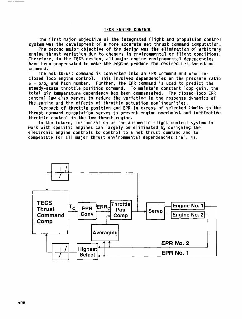
TECS ENGINE CONTROL
The first major objective of the integrated flight and propulsion control system was the development of a more accurate net thrust command computation.
The second major objective of the design was the elimination of arbitrary engine thrust variation due to changes in environmental or flight conditions. Therefore, in the TECS design, all major engine environmental dependencies have been compensated to make the engine produce the desired net thrust on comand.
The net thrust command is converted into an EPR command and used for closed-loop engine control. This involves dependencies on the pressure ratio 15 = p/p0 and Mach number. Further, the EPR command is used to predict the steady-state throttle position comand. To maintain constant loop gain, the total air temperature dependency has been compensated. The closed-loop EPR control law also serves to reduce the variation in the response dynamics of the engine and the effects of throttle actuation nonlinearities.
Feedback of throttle position and EPR in excess of selected limits to the thrust command computation serves to prevent engine overboost and ineffective throttle control in the low thrust region.
In the future, customization of the automatic flight control system to work with specific engines can largely be eliminated by designing the electronic engine controls to control to a net thrust command and to compensate for all major thrust environmental dependencies (ref. 4).
TECS Thrust Command Comp
I Averaging . 1
* A
-m ---+ Servo
- Engine No. 2 -
EPR No. 2
EPR No. 1
7 Highest’ Select . e
406
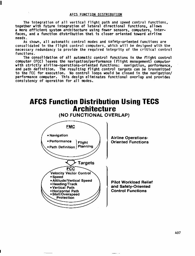
AFCS FUNCTION OISTRIBUTION
The integration of all vertical flight path and speed control functions, together with future integration of lateral directional functions, allows a more efficient system architecture using fewer sensors, computers, inter- faces, and a function distribution that is closer oriented toward airline needs.
As shown, all automatic control modes and safety-oriented functions are consolidated in the flight control computers, which will be designed with the necessary redundancy to provide the required integrity of the critical control functions.
The consolidation of all automatic control functions in the flight control computer (FCC) leaves the navigation/performance (flight management) computer with strictly airline-operations-oriented functions: navigation, performance, and-path definition. The resulting flight control targets can be transmitted to the FCC for execution. No control loops would be closed in the navigation/ performance computer. This design eliminates functional overlap and provides consistency of operation for all modes.
AFCS Function Distribution Using TECS Architecture
(NO FUNCTIONAL OVERLAP)
l Performance
l Altitude/Vertical Speed l Heading/Track l Vertical Path
Airline Operations- Oriented Functions
Pilot Workload Relief and Safety-Oriented Control Functions
407
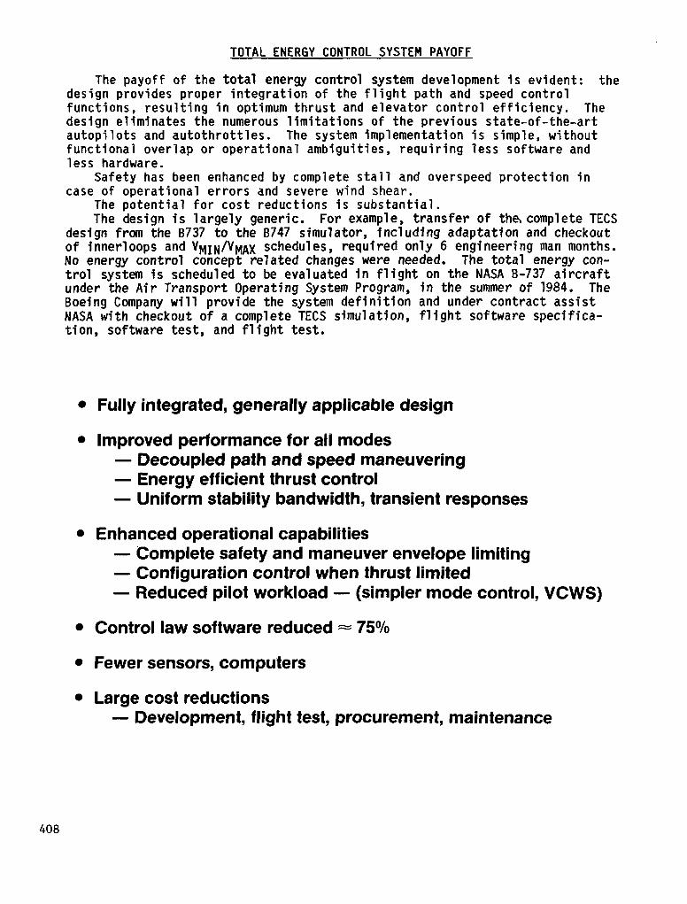
TOTAL ENERGY CONTROL SYSTEM PAYOFF
The payoff of the total energy control system development is evident: the design provides proper integration of the flight path and speed control functions, resulting in optimum thrust and elevator control efficiency. The design eliminates the numerous limitations of the previous state-of-the-art autopilots and autothrottles. The system implementation is simple, without functional overlap or operational ambiguities, requiring less software and less hardware.
Safety has been enhanced by complete stall and overspeed protection in case of operational errors and severe wind shear.
The potential for cost reductions is substantial. The design is largely generic. For example, transfer of the, complete TECS
design from the 8737 to the B747 simulator, including adaptation and checkout of innerloops and VMIN/V~X schedules, required only 6 engineering man months. No energy control concept related changes were needed. The total energy con- trol system is scheduled to be evaluated in flight on the NASA B-737 aircraft under the Air Transport Operating System Program, in the summer of 1984. The Boeing Company will provide the system definition and under contract assist NASA with checkout of a complete TECS simulation, flight software specifica- tion, software test, and flight test.
l Fully integrated, generally applicable design
l Improved performance for all modes - Decoupled path and speed maneuvering - Energy efficient thrust control - Uniform stability bandwidth, transient responses
l Enhanced operational capabilities - Complete safety and maneuver envelope limiting - Configuration control when thrust limited - Reduced pilot workload - (simpler mode control, VCWS)
l Control law software reduced = 75%
l Fewer sensors, computers
l Large cost reductions - Development, flight test, procurement, maintenance
408
REFERENCES
1. H. A. Soul& "The Throttles Control Speed, Right? Wrong!" AIAA Journal of Astronaut. & Aeronaut., vol. 7, no. 72, Dec. 7969, pp. 74-75 and 81.
2. A. A. Lambregts, "Operational Aspects of the Integrated Vertical Flight Path and Speed Control System," SAE Paper No. 831420, October 1983.
3. A. A. Lambregts and 0. G. Cannon, "Development of a Control Wheel Steering Mode and Suitable Displays That Reduce Pilot Workload and Improve Efficiency and Safety of Operation in the Terminal Area and in Windshear," AIAA Paper No. 79-1887, August 1979.
4. A. A. Lambregts, "Integrated System Design for Flight and Propulsion Control Using Total Energy Principles," AIAA Paper No. 83-2561, October 1983.
409