
Fulltext- Explicacion de Principales Teorias
15
SPECIAL ISSUE PAPER 197 Developments in modelling of metal cutting processes S L Soo ∗ and D K Aspinwall Department of Mechanical and Manufacturing Engineering, School of Engineering, The University of Birmingham, Edgbaston, Birmingham, UK The manuscript was received on 25 May 2007 and was accepted after revision for publication on 18 July 2007. DOI: 10.1243/14644207JMDA163 Abstract: Following a brief historical perspective on the development of orthogonal cutting model’s, including key work by Merchant and Oxley, the paper concentrates on the use of finite element techniques to simulate two-dimensional orthogonal turning and the subsequent tran- sition to three-dimensional formulations, thus enabling milling and drilling to be realistically modelled. Input requirements including material models, mechanical property data at elevated strain rates and temperatures, contact conditions, and other boundary conditions needed to ensure accurate simulation and predictions are discussed. Current academic research and com- mercial developments involving simulation of non-conventional processes, microscale cutting, workpiece surface integrity, and microstructure modelling, etc., are also highlighted. Keywords: finite element modelling, machining, three dimensional 1 INTRODUCTION The development of models to predict physical behaviour during metal cutting, has been a major preoccupation within the machining research com- munity over the past 60 years. From an economic viewpoint, it is evident that the ability to forecast key process parameters such as tool life, cutting forces, component surface roughness, and workpiece sur- face integrity, would be highly desirable as a means of realizing cost savings, increased productivity, and efficiency. Much of the early work revolved around analytical models that represented the basic physics and mechanics of metal cutting, using mathematical relationships. With these equations, the shear angle, tool/workpiece stresses, cutting forces, and tempera- tures can be estimated. However, all analytical models are based on simplifying assumptions that do not necessarily hold true under certain conditions. Nev- ertheless, despite such inherent weaknesses, research has continued to the present day in an effort to create more reliable and accurate models. ∗ Corresponding author: Department of Mechanical and Man- ufacturing Engineering, School of Engineering, The University of Birmingham, Edgbaston, Birmingham B15 2TT, UK. email: [email protected] The advent of computer-based simulation and in particular development of the finite element (FE) method, arguably brought about a ‘step change’ in the modelling of machining processes. First used by Tay et al. [1] in the early 1970s and subsequently by many other manufacturing researchers worldwide, the technique has proven to be a powerful and compre- hensive tool for studying the metal cutting process. Among the many advantages offered by FE simula- tion over traditional mechanistic models is the ability to accommodate the non-linear nature of the process within the analysis. It is possible to undertake simu- lation of chip morphologies, evaluation of the effects of tool geometry (e.g. nose radius, etc.) and analysis of process variables with output measures such as cut- ting forces, temperature, and workpiece/tool stresses, over the duration of the cutting operation. 2 ORTHOGONAL CUTTING MODEL ‘Orthogonal cutting’ is a term that was coined to describe the case where the cutting edge of the tool is straight and normal to both the cutting and feed direction. Piispanen [2], was the first to introduce a model to illustrate the orthogonal cutting process in the late 1930s. His so-called ‘card model’ involv- ing ‘blockwise slip’ depicted the workpiece material being cut as a ‘stack of cards’, where thin lamella’s JMDA163 © IMechE 2007 Proc. IMechE Vol. 221 Part L: J. Materials: Design and Applications
-
Upload
jonathan-catalan-avalos -
Category
Documents
-
view
28 -
download
1
Transcript of Fulltext- Explicacion de Principales Teorias

SPECIAL ISSUE PAPER 197
Developments in modelling of metal cutting processesS L Soo∗ and D K AspinwallDepartment of Mechanical and Manufacturing Engineering, School of Engineering, The University of Birmingham,Edgbaston, Birmingham, UK
The manuscript was received on 25 May 2007 and was accepted after revision for publication on 18 July 2007.
DOI: 10.1243/14644207JMDA163
Abstract: Following a brief historical perspective on the development of orthogonal cuttingmodel’s, including key work by Merchant and Oxley, the paper concentrates on the use of finiteelement techniques to simulate two-dimensional orthogonal turning and the subsequent tran-sition to three-dimensional formulations, thus enabling milling and drilling to be realisticallymodelled. Input requirements including material models, mechanical property data at elevatedstrain rates and temperatures, contact conditions, and other boundary conditions needed toensure accurate simulation and predictions are discussed. Current academic research and com-mercial developments involving simulation of non-conventional processes, microscale cutting,workpiece surface integrity, and microstructure modelling, etc., are also highlighted.
Keywords: finite element modelling, machining, three dimensional
1 INTRODUCTION
The development of models to predict physicalbehaviour during metal cutting, has been a majorpreoccupation within the machining research com-munity over the past 60 years. From an economicviewpoint, it is evident that the ability to forecast keyprocess parameters such as tool life, cutting forces,component surface roughness, and workpiece sur-face integrity, would be highly desirable as a meansof realizing cost savings, increased productivity, andefficiency. Much of the early work revolved aroundanalytical models that represented the basic physicsand mechanics of metal cutting, using mathematicalrelationships. With these equations, the shear angle,tool/workpiece stresses, cutting forces, and tempera-tures can be estimated. However, all analytical modelsare based on simplifying assumptions that do notnecessarily hold true under certain conditions. Nev-ertheless, despite such inherent weaknesses, researchhas continued to the present day in an effort to createmore reliable and accurate models.
∗Corresponding author: Department of Mechanical and Man-
ufacturing Engineering, School of Engineering, The University
of Birmingham, Edgbaston, Birmingham B15 2TT, UK. email:
The advent of computer-based simulation and inparticular development of the finite element (FE)method, arguably brought about a ‘step change’ inthe modelling of machining processes. First used byTay et al. [1] in the early 1970s and subsequently bymany other manufacturing researchers worldwide, thetechnique has proven to be a powerful and compre-hensive tool for studying the metal cutting process.Among the many advantages offered by FE simula-tion over traditional mechanistic models is the abilityto accommodate the non-linear nature of the processwithin the analysis. It is possible to undertake simu-lation of chip morphologies, evaluation of the effectsof tool geometry (e.g. nose radius, etc.) and analysis ofprocess variables with output measures such as cut-ting forces, temperature, and workpiece/tool stresses,over the duration of the cutting operation.
2 ORTHOGONAL CUTTING MODEL
‘Orthogonal cutting’ is a term that was coined todescribe the case where the cutting edge of the toolis straight and normal to both the cutting and feeddirection. Piispanen [2], was the first to introducea model to illustrate the orthogonal cutting processin the late 1930s. His so-called ‘card model’ involv-ing ‘blockwise slip’ depicted the workpiece materialbeing cut as a ‘stack of cards’, where thin lamella’s
JMDA163 © IMechE 2007 Proc. IMechE Vol. 221 Part L: J. Materials: Design and Applications
198 S L Soo and D K Aspinwall
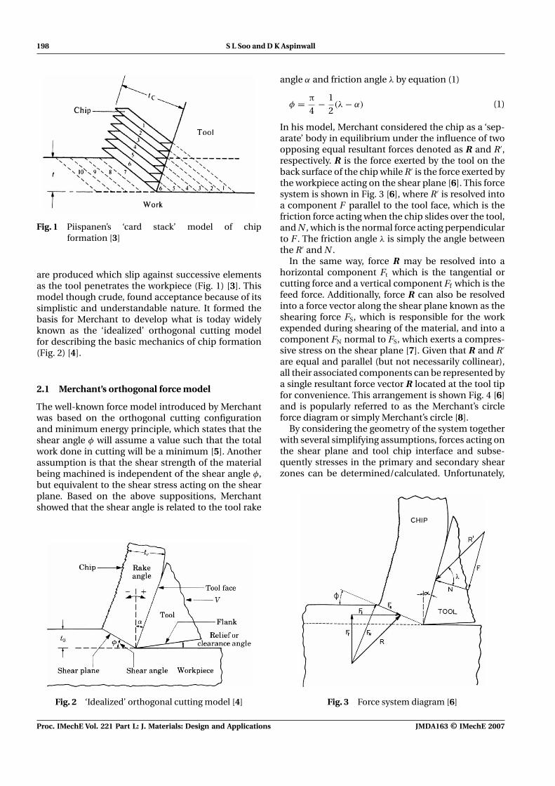
Fig. 1 Piispanen’s ‘card stack’ model of chipformation [3]
are produced which slip against successive elementsas the tool penetrates the workpiece (Fig. 1) [3]. Thismodel though crude, found acceptance because of itssimplistic and understandable nature. It formed thebasis for Merchant to develop what is today widelyknown as the ‘idealized’ orthogonal cutting modelfor describing the basic mechanics of chip formation(Fig. 2) [4].
2.1 Merchant’s orthogonal force model
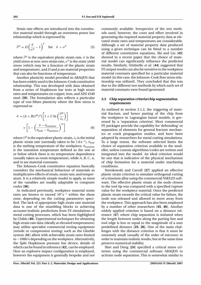
The well-known force model introduced by Merchantwas based on the orthogonal cutting configurationand minimum energy principle, which states that theshear angle φ will assume a value such that the totalwork done in cutting will be a minimum [5]. Anotherassumption is that the shear strength of the materialbeing machined is independent of the shear angle φ,but equivalent to the shear stress acting on the shearplane. Based on the above suppositions, Merchantshowed that the shear angle is related to the tool rake
Fig. 2 ‘Idealized’ orthogonal cutting model [4]
angle α and friction angle λ by equation (1)
φ = π
4− 1
2(λ − α) (1)
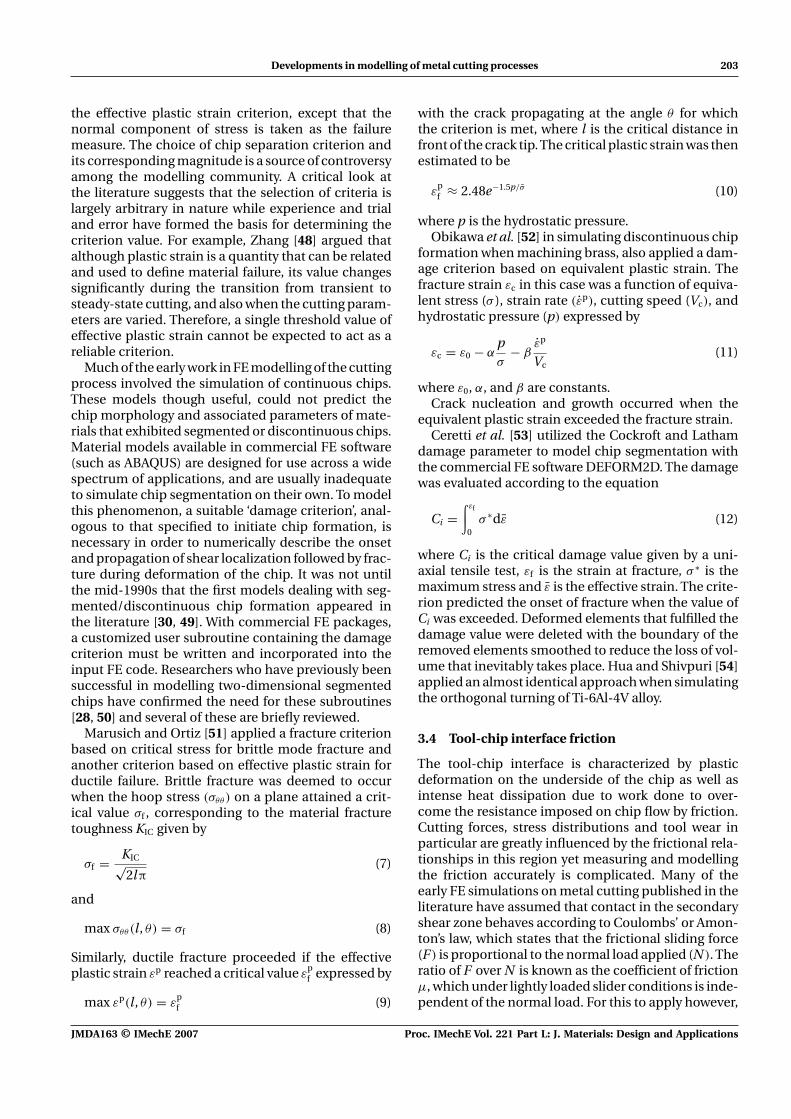
In his model, Merchant considered the chip as a ‘sep-arate’ body in equilibrium under the influence of twoopposing equal resultant forces denoted as R and R′,respectively. R is the force exerted by the tool on theback surface of the chip while R′ is the force exerted bythe workpiece acting on the shear plane [6]. This forcesystem is shown in Fig. 3 [6], where R′ is resolved intoa component F parallel to the tool face, which is thefriction force acting when the chip slides over the tool,and N , which is the normal force acting perpendicularto F . The friction angle λ is simply the angle betweenthe R′ and N .
In the same way, force R may be resolved into ahorizontal component Ft which is the tangential orcutting force and a vertical component Ff which is thefeed force. Additionally, force R can also be resolvedinto a force vector along the shear plane known as theshearing force FS, which is responsible for the workexpended during shearing of the material, and into acomponent FN normal to FS, which exerts a compres-sive stress on the shear plane [7]. Given that R and R′
are equal and parallel (but not necessarily collinear),all their associated components can be represented bya single resultant force vector R located at the tool tipfor convenience. This arrangement is shown Fig. 4 [6]and is popularly referred to as the Merchant’s circleforce diagram or simply Merchant’s circle [8].
By considering the geometry of the system togetherwith several simplifying assumptions, forces acting onthe shear plane and tool chip interface and subse-quently stresses in the primary and secondary shearzones can be determined/calculated. Unfortunately,
Fig. 3 Force system diagram [6]
Proc. IMechE Vol. 221 Part L: J. Materials: Design and Applications JMDA163 © IMechE 2007

Developments in modelling of metal cutting processes 199
Fig. 4 Merchant’s circle force diagram [6]
when applied to a range of workpiece materials, themodel does not provide accurate results, indeed it doesnot satisfactorily account for the influence of parame-ters such as cutting speed on machining behaviour [8].The description of friction at the tool/chip interfaceusing the Coulomb model is also thought to contributeto the weakness of the analysis. Nevertheless, Mer-chant’s circle remains an important milestone in metalcutting theory as it provides fundamental insight intothe forces and stresses involved in machining.
2.2 Oxley’s parallel sided shear zone theory
In re-examining Merchant’s theory with regard toshear angle prediction, Oxley found that whena wide range of cutting conditions was applied,Merchant’s theory showed very poor quantitativeagreement with experimentally measured values [9].Oxley subsequently criticized some of the necessaryassumptions, not least the disregard of effects due tostrain hardening, strain rate etc. [10]. Oxley and Welsh[11] introduced a new predictive analytical model todescribe the orthogonal cutting process which tookaccount of such aspects; furthermore, direct obser-vations of chip formation indicated that shearingactually occurred within a finite plastic zone insteadof on a simple shear plane (Fig. 5).
The Oxley and Welsh model represented this finiteplastic zone in the form of a parallel-sided shear zoneas shown in Fig. 6. Here the shear plane AB is assumedto extend to the boundaries marked by CD and EF,respectively, which are parallel and equidistant to ABand form the shear zone. The lines CD and EF like
Fig. 5 Chip formation occurring within a finite plasticzone [11]
AB are sliplines that represent the directions of max-imum shear stress and shear strain rate. The workvelocity is assumed to change to the chip velocityin the shear zone without any discontinuities, how-ever, the resultant force R does not in general passthrough the midpoint of AB. Furthermore, chip curl isneglected, while the state of strain and consequentlythe shear flow stress along each of the parallel sliplinesis constant [11]. The method of analysis involveddetermining the stresses along AB as a function of theshear angle and work material properties, and subse-quently selecting a value for φ such that the resultantforce transmitted by AB is in equilibrium with thefrictional conditions at the tool-chip interface (con-sistent with the direction of λ) [12]. Once the shearangle is found, various other components of forcecan be determined. A full description and treatmentof the theory can be found in reference [12]. Despite
Fig. 6 Parallel sided shear zone model [11]
JMDA163 © IMechE 2007 Proc. IMechE Vol. 221 Part L: J. Materials: Design and Applications

200 S L Soo and D K Aspinwall
the obvious improvements in Oxley and Welsh’s modelover some of its predecessor’s, the lack of sufficientstress/strain data at the level of strain rates and tem-peratures encountered in machining is a significantlimitation.
In addition to the shear angle based equations suchas those developed by Merchant and Oxley for deter-mining forces, stresses, strain, etc., there has alsobeen numerous theoretical models developed over theyears for the prediction of cutting temperatures at thetool-chip interface and shear plane, such as those byTrigger and Chao [13], Boothroyd [14], and Hou andKomanduri [15] to name but a few. Successive ana-lytical models have improved upon their predecessorsand given tremendous insight into the mechanics ofthe chip formation process. Despite the advantagesoffered by such solutions, analytical models have lim-ited practical application while many of the respectiveunderlying assumptions do not hold true for a greatmany materials and cutting conditions.
3 FE MODELLING
In the two decades following Tay et al.’s [1] pio-neering work, academic research continued to centremainly on two-dimensional, orthogonal-based mod-els with workpiece materials ranging from low car-bon steel, copper, stainless, and hardened steels tomore exotic alloys such as titanium and nickel basedsuperalloys (Inconel 718). The following sections dis-cuss the key requirements for realistic FE simula-tion of metal cutting, together with the more recentthrust towards more complex/representative three-dimensional-based models, including processes otherthan turning. Finally, recent developments which havefocused on areas such as surface integrity prediction(residual stress, microstructure, etc.) after machiningas well as simulation of microscale mechanical cut-ting and non-traditional machining processes suchelectrical discharge machining (EDM) are presented.
3.1 Model formulation
This refers to the way in which the FE mesh is ‘asso-ciated’ with the workpiece material. The three mainformulations are the Eulerian, Lagrangian, and thearbitrary Lagrangian–Eulerian (ALE).
3.1.1 Eulerian
In the Eulerian representation, the FE grid is spatiallyfixed, with the material flowing through the meshedcontrol volume [16]. The unknown material variablesare calculated at set locations as the material flowsthrough the mesh. Eulerian based models are free fromelement distortion problems as their shapes do not
alter throughout the course of the simulation, andhence no remeshing is necessary, which is a key bene-fit in terms of computational efficiency. Furthermore,a chip separation criterion to designate the parting ofnodes between the workpiece and chip is not required,as the material is not attached to the mesh. The natureof Eulerian type formulations, however, means that theinitial shape of chip and contact conditions must beknown or assumed in advance. This then excludes thepossibility of modelling unconstrained flow of mate-rial at the free boundaries and the natural formationof the chip as the result of deformation. The free sur-faces of the chip must therefore be adjusted manuallyduring a simulation, usually through an iterative pro-cedure [17]. In general, this involves checking thevelocities at the nodes along the free boundaries toensure that their components, which are normal toit, are zero and that other variables have converged[18]. The geometry of the chip is then updated with thecomputed velocities tangential to the free surfaces.
The method is suitable for studying steady-statecutting, where the relatively lengthy transition fromtransient incipient chip formation to steady-state con-ditions are not of interest [19]. Strenkowski and Moon[20] utilized an Eulerian FE model to predict steady-state chip geometry and chip/tool contact length. Thelatter parameter was determined by inspecting thenormal stress at each node along the tool-chip inter-face. A positive magnitude meant that the particularnode had been released from the interface. Althoughreasonable predictions have been reported by severalinvestigators using Eulerian based models [21, 22], itis widely agreed to be better suited for fluid mechanicsproblems rather than for machining.
3.1.2 Lagrangian
Here the FE mesh is attached to the workpiece materialand the elements deform together with the mate-rial during cutting. This makes it highly suitable forsolid mechanics analysis and appropriate for prob-lems where unconstrained material flow is involved[18]. For metal cutting simulations, the Lagrangianformulation is preferable due to the more convenientmodelling of the evolution of the chip from the incip-ient stage to steady. The geometry of the materialboundaries (or chip shape) does not have to be pre-determined, but develops during the course of theanalysis entirely as a function of the physical defor-mation process, machining parameters, and materialproperties [23].
The principal disadvantage of the Lagrangianapproach in machining simulations is that as the ele-ments generally experience severe distortion, geomet-rical as well as material non-linearities are introducedin the FE equations [17] that considerably increase thecomputational load. This poses substantial numerical
Proc. IMechE Vol. 221 Part L: J. Materials: Design and Applications JMDA163 © IMechE 2007

Developments in modelling of metal cutting processes 201
difficulties, which occasionally requires the mesh tobe regenerated to prevent the simulation from ‘break-ing down’ prematurely, besides adversely impactingon the efficiency and accuracy of the analysis. InLagrangian based models, the parting of the chip fromthe workpiece is traditionally achieved via separationof nodes in front of the tool tip along a predefinedline representing the depth of cut [24–27]. The nodeseparation procedure is governed by a material fail-ure condition, which is a function of one of severalcriteria and although simple and straightforward, themethodology does possess drawbacks. With the largedeformations encountered during metal cutting, thereis a tendency for the nodes in front of the tool along theparting line to be ‘pushed’ out of position, thus caus-ing ‘entanglement’ of the elements with the cuttingtool. Premature separation of nodes resulting in a gapin front of the tool tip is another common problem,which is usually caused by inappropriate specifica-tion of the magnitude of the separation criterion.Such effects contribute to reducing the accuracy andvalidity of the results. More recently, however, severalresearchers have investigated alternative methods ofachieving the cutting action such as element deletion[28, 29] and adaptive remeshing [30].
3.1.3 Arbitrary Lagrangian Eulerian (ALE)
The ALE procedure can be described as a gen-eral formulation that amalgamates both the classicalLagrangian and Eulerian techniques into one descrip-tion in order to exploit their respective merits. The FEmesh in an ALE simulation is neither fixed spatiallynor attached to the material, but instead is allowed tomove arbitrarily relative to the material [31]. The for-mulation is such that it can be reduced to Eulerianor Lagrangian descriptions as and when required [32].For metal cutting simulations, the idea is generally toapply features of the Eulerian type approach for mod-elling the area around the tool tip, while the Lagrangianform can be utilized for modelling the unconstrainedflow of material at the free boundaries [33]. In thisway, the problem of severe element distortion andentanglement in the cutting zone can be alleviatedwithout the need for remeshing. Furthermore the evo-lution of the shape and size of the chip can occurfreely and automatically as a function of the materialdeformation. A number of researchers have studiedthe problem of orthogonal turning with continuouschips using the ALE procedure [34, 35].
3.2 Workpiece material constitutiveequations/material properties testing
Constitutive equations describe the mechanicalbehaviour of the workpiece material undergoing load-ing and deformation, and are an essential input in any
FEM model. Under machining conditions, the work-piece material is generally subjected to high levels ofheat, strain and strain rate, which significantly influ-ences flow stress. In FE simulations, an ideal plasticitymodel for the workpiece would be one that can reli-ably describe the stress–strain response together withits dependence on strain-rate, temperature and workhardening [36]. The material property data for con-stitutive modelling was previously acquired throughstandard mechanical testing such as tension, com-pression, torsion or impact experiments. However,these test methods normally cannot attain the level ofstrains and strain rates that are encountered in typicalmachining processes [37]. Assumptions are there-fore customarily introduced according to the need ofthe application, partly to overcome the inadequaciesimposed by the experimentally obtained material dataand to simplify the modelling [36]. A brief discussion oftwo of the general constitutive plasticity models withstrain rate and temperature dependence that are avail-able in the commercial FE software ABAQUS (widelyused for metal cutting simulations) is presented.
The level of plastic deformation is such in the pri-mary and secondary shear zones that many modellersdiscount the elastic response of the workpiece mate-rial in their simulations for the sake of expediency.Nonetheless, elastic straining although small (usuallyof the order 10−3), does influence aspects such asthe residual stress and strain distribution in the chipand workpiece. In ABAQUS, the elastic (recoverable)and inelastic (non-recoverable) responses are separa-ble based on an assumption that there is an additiverelationship between the strain rate [38], such that
ε̇ = ε̇el + ε̇pl (2)
where ε̇ is the total strain rate, ε̇el the rate of changeof elastic strain, and ε̇pl the rate of change of plasticstrain.
The elastic response is modelled by the relativelysimple linear elasticity relationship given by
σ = Del: εel (3)
where σ is the total stress, εel the elastic strain, andDel is the elasticity tensor matrix that may depend ontemperature.
The classical plasticity model available in ABAQUSis based on the von-Mises yield surface used to defineisotropic yielding and hardening. Isotropic yieldingoccurs when the yield stress increases in all directionsas plastic straining occurs. The yield function can bewritten as
f (σ ) = σ0(εpl, θ) (4)
where σ0 is the equivalent (uniaxial) stress, εpl theplastic strain, and θ the temperature.
JMDA163 © IMechE 2007 Proc. IMechE Vol. 221 Part L: J. Materials: Design and Applications
202 S L Soo and D K Aspinwall
Strain rate effects are introduced into the constitu-tive material model through an overstress power lawrelationship which is expressed by
˙̄εpl = D(
σ̄
σ 0− 1
)p
for σ̄ > σ 0 (5)
where ˙̄εpl is the equivalent plastic strain rate, σ̄ is theyield stress at non-zero strain rate, σ 0 is the static yieldstress (which may be a function of the plastic strainand temperature), and D and p are material propertiesthat can also be functions of temperature.
Another plasticity model provided in ABAQUS thathas been widely used is the Johnson–Cook constitutiverelationship. This was developed with data obtainedfrom a series of Hopkinson bar tests at high strainrates and temperatures on copper, iron, and AISI 4340steel [39]. The formulation also reflects a particulartype of von-Mises plasticity where the flow stress isexpressed as
σ̄ = [A + B(ε̄pl)n][
1 + C ln( ˙̄εpl
ε̇0
)]
×[
1 −(
θ − θtransition
θmelt − θtransition
)m](6)
where ε̄pl is the equivalent plastic strain, ε̇0 is the initialplastic strain rate (normally taken to be 1.0 s−1), θmelt
is the melting temperature of the workpiece, θtransition
is the transition temperature defined as the one ator below which there is no temperature dependence(usually taken as room temperature), while A, B, C , n,and m are material constants.
The Johnson–Cook constitutive equation basicallyconsiders the mechanical behaviour of materials asmultiplicative effects of strain, strain rate, and temper-ature. It is a relatively simple model to apply, as mostof the variables are readily adaptable to computercodes [36].
As indicated previously, workpiece material strainrates are known to exceed 104 s−1 within the shearzone, depending on the cutting parameters speci-fied. The lack of appropriate high strain rate materialdata is one of the stumbling blocks to achievingaccurate/realistic predictions from FE simulations ofmetal cutting processes, which has been highlightedby Childs [40]. Experimental techniques for obtaininghigh strain rate data (ideally at elevated temperatures)may utilize specialist commercial testing equipment(tensile or compression testing) such as the Gleeblesystem [41] albeit with achievable strain rates limitedto ∼1000/s depending on the workpiece. Alternatively,the Split Hopkinson pressure bar device, details ofwhich can be found in reference [42], can be employed.Here an explosive impact configuration is employed,however the equipment is generally bespoke and not
commonly available. Irrespective of the test meth-ods used, however, the costs and effort involved ingenerating the required material property data at ele-vated strain rates and temperatures are considerable.Although a set of material property data producedusing a given technique can be fitted to a numberof different constitutive equations, Shi and Liu [43]showed in a recent paper that the choice of mate-rial model can significantly influence the predictedresults. Similarly, Umbrello et al. [44] suggested thatFE output results can also be sensitive to the workpiecematerial constants specified for a particular materialmodel (in this case, the Johnson–Cook flow stress rela-tionship was utilized). They concluded that this wasdue to the different test methods by which each set ofmaterial constants were found/generated.
3.3 Chip separation criteria/chip segmentationrequirements
As outlined in section 3.1.2, the triggering of mate-rial fracture, and hence parting of the chip fromthe workpiece in Lagrangian based models, is gov-erned by a ‘separation criterion’. Most commercialFE packages provide the capability for ‘debonding’ orseparation of elements for general fracture mechan-ics or crack propagation studies, and have beenadopted by researchers for metal cutting simulations.To a large extent, the software selected limits thechoice of separation criterion available to the mod-eller, unless custom algorithms/codes are written andintegrated into the model. An ideal criterion wouldbe one that is indicative of the physical mechanismof chip formation for a material under machiningconditions.
Strenkowski and Carroll [27] applied an effectiveplastic strain criterion to simulate orthogonal cuttingof a titanium alloy using the commercial NIKE2D soft-ware. The effective plastic strain at the node closestto the tool tip was compared with a specified rupturevalue for the workpiece material. Once the predictedplastic strain exceeds the critical value for failure, thenode was released and allowed to move away fromthe workpiece. This approach has also been employedby a number of other researchers [45, 46]. Anotherwidely applied criterion is based on a distance tol-erance [47] where chip separation is initiated whenthe length between nodes along the parting line andtool edge is less or equal to the magnitude of a userpredefined distance [25, 26]. One of the main chal-lenges with the distance criterion is that it must beextremely small (usually of the order of microns) inorder to maintain realistic results, but at the same timepreserve numerical stability.
Shet and Deng [24] specified a critical stress cri-terion using the commercial software ABAQUS toactivate node separation. This is somewhat similar to
Proc. IMechE Vol. 221 Part L: J. Materials: Design and Applications JMDA163 © IMechE 2007
Developments in modelling of metal cutting processes 203
the effective plastic strain criterion, except that thenormal component of stress is taken as the failuremeasure. The choice of chip separation criterion andits corresponding magnitude is a source of controversyamong the modelling community. A critical look atthe literature suggests that the selection of criteria islargely arbitrary in nature while experience and trialand error have formed the basis for determining thecriterion value. For example, Zhang [48] argued thatalthough plastic strain is a quantity that can be relatedand used to define material failure, its value changessignificantly during the transition from transient tosteady-state cutting, and also when the cutting param-eters are varied. Therefore, a single threshold value ofeffective plastic strain cannot be expected to act as areliable criterion.
Much of the early work in FE modelling of the cuttingprocess involved the simulation of continuous chips.These models though useful, could not predict thechip morphology and associated parameters of mate-rials that exhibited segmented or discontinuous chips.Material models available in commercial FE software(such as ABAQUS) are designed for use across a widespectrum of applications, and are usually inadequateto simulate chip segmentation on their own. To modelthis phenomenon, a suitable ‘damage criterion’, anal-ogous to that specified to initiate chip formation, isnecessary in order to numerically describe the onsetand propagation of shear localization followed by frac-ture during deformation of the chip. It was not untilthe mid-1990s that the first models dealing with seg-mented/discontinuous chip formation appeared inthe literature [30, 49]. With commercial FE packages,a customized user subroutine containing the damagecriterion must be written and incorporated into theinput FE code. Researchers who have previously beensuccessful in modelling two-dimensional segmentedchips have confirmed the need for these subroutines[28, 50] and several of these are briefly reviewed.
Marusich and Ortiz [51] applied a fracture criterionbased on critical stress for brittle mode fracture andanother criterion based on effective plastic strain forductile failure. Brittle fracture was deemed to occurwhen the hoop stress (σθθ ) on a plane attained a crit-ical value σf , corresponding to the material fracturetoughness KIC given by
σf = KIC√2lπ
(7)
and
max σθθ (l, θ) = σf (8)
Similarly, ductile fracture proceeded if the effectiveplastic strain εp reached a critical value ε
pf expressed by
max εp(l, θ) = εpf (9)
with the crack propagating at the angle θ for whichthe criterion is met, where l is the critical distance infront of the crack tip. The critical plastic strain was thenestimated to be
εpf ≈ 2.48e−1.5p/σ̄ (10)
where p is the hydrostatic pressure.Obikawa et al. [52] in simulating discontinuous chip
formation when machining brass, also applied a dam-age criterion based on equivalent plastic strain. Thefracture strain εc in this case was a function of equiva-lent stress (σ ), strain rate (ε̇p), cutting speed (Vc), andhydrostatic pressure (p) expressed by
εc = ε0 − αpσ
− βε̇p
Vc(11)
where ε0, α, and β are constants.Crack nucleation and growth occurred when the
equivalent plastic strain exceeded the fracture strain.Ceretti et al. [53] utilized the Cockroft and Latham
damage parameter to model chip segmentation withthe commercial FE software DEFORM2D. The damagewas evaluated according to the equation
Ci =∫ εf
0σ ∗dε̄ (12)
where Ci is the critical damage value given by a uni-axial tensile test, εf is the strain at fracture, σ ∗ is themaximum stress and ε̄ is the effective strain. The crite-rion predicted the onset of fracture when the value ofCi was exceeded. Deformed elements that fulfilled thedamage value were deleted with the boundary of theremoved elements smoothed to reduce the loss of vol-ume that inevitably takes place. Hua and Shivpuri [54]applied an almost identical approach when simulatingthe orthogonal turning of Ti-6Al-4V alloy.
3.4 Tool-chip interface friction
The tool-chip interface is characterized by plasticdeformation on the underside of the chip as well asintense heat dissipation due to work done to over-come the resistance imposed on chip flow by friction.Cutting forces, stress distributions and tool wear inparticular are greatly influenced by the frictional rela-tionships in this region yet measuring and modellingthe friction accurately is complicated. Many of theearly FE simulations on metal cutting published in theliterature have assumed that contact in the secondaryshear zone behaves according to Coulombs’ or Amon-ton’s law, which states that the frictional sliding force(F ) is proportional to the normal load applied (N ). Theratio of F over N is known as the coefficient of frictionμ, which under lightly loaded slider conditions is inde-pendent of the normal load. For this to apply however,
JMDA163 © IMechE 2007 Proc. IMechE Vol. 221 Part L: J. Materials: Design and Applications
204 S L Soo and D K Aspinwall
N must be below a certain critical value. As the normalforce increases, Coulombs’ equation no longer holdstrue as the real area of contact between the chip andtool rake face increases [3]. This is known as a highlyloaded slider state.
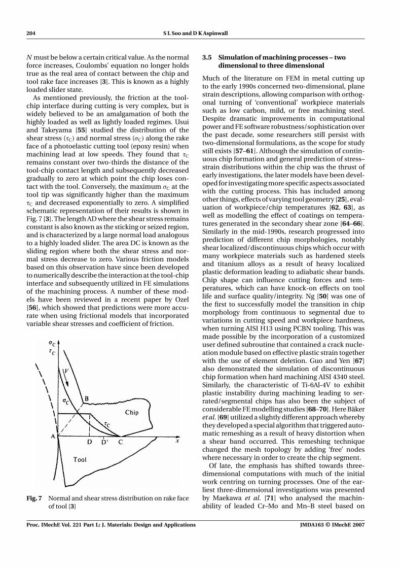
As mentioned previously, the friction at the tool-chip interface during cutting is very complex, but iswidely believed to be an amalgamation of both thehighly loaded as well as lightly loaded regimes. Usuiand Takeyama [55] studied the distribution of theshear stress (τC) and normal stress (σC) along the rakeface of a photoelastic cutting tool (epoxy resin) whenmachining lead at low speeds. They found that τC
remains constant over two-thirds the distance of thetool-chip contact length and subsequently decreasedgradually to zero at which point the chip loses con-tact with the tool. Conversely, the maximum σC at thetool tip was significantly higher than the maximumτC and decreased exponentially to zero. A simplifiedschematic representation of their results is shown inFig. 7 [3]. The length AD where the shear stress remainsconstant is also known as the sticking or seized region,and is characterized by a large normal load analogousto a highly loaded slider. The area DC is known as thesliding region where both the shear stress and nor-mal stress decrease to zero. Various friction modelsbased on this observation have since been developedto numerically describe the interaction at the tool-chipinterface and subsequently utilized in FE simulationsof the machining process. A number of these mod-els have been reviewed in a recent paper by Ozel[56], which showed that predictions were more accu-rate when using frictional models that incorporatedvariable shear stresses and coefficient of friction.
Fig. 7 Normal and shear stress distribution on rake faceof tool [3]
3.5 Simulation of machining processes – twodimensional to three dimensional
Much of the literature on FEM in metal cutting upto the early 1990s concerned two-dimensional, planestrain descriptions, allowing comparison with orthog-onal turning of ‘conventional’ workpiece materialssuch as low carbon, mild, or free machining steel.Despite dramatic improvements in computationalpower and FE software robustness/sophistication overthe past decade, some researchers still persist withtwo-dimensional formulations, as the scope for studystill exists [57–61]. Although the simulation of contin-uous chip formation and general prediction of stress–strain distributions within the chip was the thrust ofearly investigations, the later models have been devel-oped for investigating more specific aspects associatedwith the cutting process. This has included amongother things, effects of varying tool geometry [25], eval-uation of workpiece/chip temperatures [62, 63], aswell as modelling the effect of coatings on tempera-tures generated in the secondary shear zone [64–66].Similarly in the mid-1990s, research progressed intoprediction of different chip morphologies, notablyshear localized/discontinuous chips which occur withmany workpiece materials such as hardened steelsand titanium alloys as a result of heavy localizedplastic deformation leading to adiabatic shear bands.Chip shape can influence cutting forces and tem-peratures, which can have knock-on effects on toollife and surface quality/integrity. Ng [50] was one ofthe first to successfully model the transition in chipmorphology from continuous to segmental due tovariations in cutting speed and workpiece hardness,when turning AISI H13 using PCBN tooling. This wasmade possible by the incorporation of a customizeduser defined subroutine that contained a crack nucle-ation module based on effective plastic strain togetherwith the use of element deletion. Guo and Yen [67]also demonstrated the simulation of discontinuouschip formation when hard machining AISI 4340 steel.Similarly, the characteristic of Ti-6Al-4V to exhibitplastic instability during machining leading to ser-rated/segmental chips has also been the subject ofconsiderable FE modelling studies [68–70]. Here Bäkeret al. [69] utilized a slightly different approach wherebythey developed a special algorithm that triggered auto-matic remeshing as a result of heavy distortion whena shear band occurred. This remeshing techniquechanged the mesh topology by adding ‘free’ nodeswhere necessary in order to create the chip segment.
Of late, the emphasis has shifted towards three-dimensional computations with much of the initialwork centring on turning processes. One of the ear-liest three-dimensional investigations was presentedby Maekawa et al. [71] who analysed the machin-ability of leaded Cr–Mo and Mn–B steel based on
Proc. IMechE Vol. 221 Part L: J. Materials: Design and Applications JMDA163 © IMechE 2007

Developments in modelling of metal cutting processes 205
strain rate and temperature-dependent plastic flowmaterial properties. Their model was used to predictthe stress and temperature distribution together withthe wear rate on the rake face of the cutting tool. Amore recent contribution by Li and Shih [72] looked atmodelling the effects of cutting parameters and toolgeometry on cutting forces, temperature, and chipcurl/morphology when turning commercially puretitanium. This involved an updated Lagrangian FE for-mulation together with adaptive meshing techniquesand the application of a coupled thermal and mechan-ical analysis of the tool and workpiece deformation.In general, the results of their three-dimensionalmodel were successfully validated against correspond-ing experimental data, although the tangential forcewas typically under-estimated by up to 20 per centat the lower cutting speeds tested. The discrepancywas mainly attributed to the simplified friction modelapplied and limitations in the material property data.The simulation of alternative cutting processes suchas twist drilling and milling in particular, have startedto gain prominence in the last 5 years (Figs 8 and 9).For such operations, a three-dimensional model is notonly desirable but necessary in order to fully realize
Fig. 8 Three-dimensional FE simulation of twist drillingusing DEFORM3D (courtesy of SFT Corporation)
Fig. 9 Three-dimensional FE simulation of face millingusing AdvantEdge (courtesy of ThirdWaveSystems Inc.)
the problem due to the complex geometry and rotarymotion of the cutter.
Three-dimensional processes that have been simu-lated using FE methods include the drilling of stainlesssteel as a means to evaluate burr formation [73],twist milling of AISI 4140 steel [74] and simulationof high speed ball nose end milling of Inconel 718using ABAQUS Explicit [75] (Fig. 10). By studyingthe stress contours and workpiece edge deformationpredicted by the model, Guo and Dornfeld [73] pro-posed a mechanism for burr formation comprisingfour stages. These were outlined as burr initiation,burr development, pivoting point and finally burrformation. Although the height and thickness of thesimulated burrs were not compared to experimen-tal data, the characteristics of the burr in terms ofshape and cap formation were validated by resultsfrom drilling of 304L stainless steel and plasticine.With the twist milling simulation, Bacaria et al. [74]applied the Johnson–Cook damage criterion over theentire workpiece, which allowed the natural forma-tion of the chip as the tooth of the milling cutterpenetrated the workpiece, without the need for a pre-defined fracture line (which is virtually impossible
Fig. 10 (a) Three-dimensional simulation of high speed ball nose end milling of Inconel 718 usingABAQUS Explicit; (b) to (d) showing progression of chip formation [75]
JMDA163 © IMechE 2007 Proc. IMechE Vol. 221 Part L: J. Materials: Design and Applications

206 S L Soo and D K Aspinwall
to specify due to the complex trajectory of millingoperations). The work, however, only dealt with pre-liminary chip formation aspects, together with somestress distribution and cutting force predictions andwas not validated experimentally. A more recent con-tribution has been the three-dimensional modellingof the friction drilling process involving an aluminiumalloy Al-6061-T6 using ABAQUS Explicit [76]. In con-trast to conventional twist drilling, friction drillinginvolves rotating a conical tool against a workpiecematerial such that the resulting frictional contactbetween the tool-workpiece generates sufficient heatto soften the workpiece where the axial feed providespenetration. The model by Miller and Shih [76] wasable to successfully simulate the material deformationand temperature in the workpiece and was subse-quently validated against experimental measurementof torque, thrust force, and temperature. The torquepredictions in particular were found to deviate fromthe experimental data at higher tool feed rates, whichwas due to the limitation of the Coulomb frictionmodel.
3.6 Recent developments and future research
The use of FE modelling techniques as a design or opti-mization tool for bulk deformation processes such ascasting and to a lesser extent metal forming, is rel-atively accepted and widespread, particularly withinthe aerospace industry. Unfortunately, this technologyis less developed with regard to machining processesdespite the progress detailed in the previous section.Current commercial packages are not able to predictwith reasonable reliability and accuracy aspects suchas workpiece surface integrity postmachining, whichis of paramount importance with safety critical com-ponents such as aero-engine parts. There is, however,a growing interest in developing suitable expertisewithin this area, evident from the recent increase inthe number of publications on the subject, albeit withtwo-dimensional formulations. Salio et al. [77] devel-oped a two-dimensional plane strain model usingMSC MARC to evaluate the residual stress generatedafter finish turning of Inconel 718 turbine disc materialover a wide range of cutting parameters. The predictedresults were validated against calculations from ana-lytical models as well as experimental X-ray residualstress measurements. In general, the modelled resid-ual stresses were found to give good agreement whencompared with measured data. It was observed thattensile residual stress values at the workpiece surfaceincreased with smaller depths of cut and the crossoverto a compressive state occurred at a deeper level intothe workpiece material. The work also identified pre-ferred depth of cut values to provide minimum tensileresidual stresses.
Another related area that has received significantattention is the effect of tool geometry (in particu-lar tool edge radius) and associated cutting param-eters in relation to workpiece residual stress. Huaet al. [78] studied the effects of feed rate, workpiecehardness, and tool geometry on the subsurface resid-ual stress when hard facing bearing steel AISI 52100using a Lagrangian FE approach with DEFORM2D.Their simulations showed that in all conditions tested,compressive residual stress was produced at the work-piece surface. An increase in feed rate and workpiecehardness was found to significantly raise the magni-tude of compressive stress generated, although thelatter did not alter the depth of maximum residualstress. Similarly, an increase in tool hone radius andchamfer angle gave rise to a higher maximum resid-ual stress, with the former parameter having a moredominant effect. Cutting speed was observed to haveno major impact on the residual stress response. Thepredicted results were shown to agree closely with cor-responding X-ray diffraction measurements of actualmachined surfaces. Nasr et al. [79] developed an ALEmodel in ABAQUS Explicit to investigate the effect ofvarying tool edge radius on subsurface residual stresswhen orthogonal cutting AISI 316L stainless steel.They found that an increased tool edge radius gaverise to higher tensile residual stresses at the machinedsurface but also induced larger compressive stressesdeeper into the workpiece. This was attributed to thehigher cutting temperatures generated with a largertool edge radius (wider area of contact) and the greaterplastic deformation as a result of increased materialbeing ploughed into the machined surface. Similarmethodologies to predict surface integrity have alsobeen utilized by Ee et al. [80] and Zong et al. [81] whenevaluating the orthogonal cutting of AISI 1045 steeland diamond turning of OFHC copper, respectively.The work by Ee et al. [80] also investigated the effectof sequential/subsequent cuts on the residual stressprofiles and found that although no significant changewas recorded in terms of the maximum tensile stressat the workpiece surface, the residual stresses decayedto a neutral state at half the depth compared to thecase where only a single cut was made.
In addition to residual stress, the effects of machin-ing processes on workpiece/component microstruc-ture is likewise of great interest as they can have asignificant influence on part performance, properties,and fatigue life. Chuzhoy et al. [82] presented oneof the earliest studies on modelling the machiningof ductile iron which has a heterogeneous structurecomprising pearlite and ferrite together with specifiedamounts of graphite. The microstructure of the mate-rial was successfully generated and incorporated intothe FE mesh with the distribution and average size ofthe grains chosen to be representative of the actual
Proc. IMechE Vol. 221 Part L: J. Materials: Design and Applications JMDA163 © IMechE 2007

Developments in modelling of metal cutting processes 207
material. Each of the phases was explicitly modelledwith the hexagonal shaped pearlite and ferrite grainsinterspersed throughout the material while the circu-lar graphite nodules were embedded within the ferriteparticles. Furthermore, the corresponding propertiesof each phase was individually characterized prior tothe cutting simulation and subsequently accountedfor in the material model. The orthogonal cutting sim-ulation carried out on the multi-phase material wascapable of predicting cutting forces, temperatures,stress/strain distributions together with damage andchanges within each phase. The technique was able toillustrate the effect of the material microstructure onmachinability with the potential for alternative appli-cations. More recent studies relating to microstructuremodelling when machining have included work bySimoneau et al. [83] on chip formation in orthogo-nal turning of AISI 1045 steel and Pramanik et al. [84]when investigating the tool-particle interaction incutting of SiC reinforced aluminium metal matrixcomposites.
An important class of heterogeneous materialswhich is currently receiving much attention in indus-try are fibre reinforced composite materials. As thecost of composites is inherently expensive, the abil-ity to investigate the cutting of such materials throughsimulation rather than experimentation alone is veryattractive, indeed advances in FE techniques have ledto numerous publications on the subject of modellingcomposites when orthogonal machining. A reviewof the literature indicates that there are two princi-pal methods to model the properties of composites,namely use of an equivalent homogenous mate-rial (EHM) technique and a micromechanics basedapproach. With the former, the material is definedas a single ‘homogenous structure’ with the proper-ties of the fibre and matrix combined whereas themicromechanics technique considers the fibre andmatrix properties separately within the mesh. Thisenables modelling of local material behaviour effectsduring machining but imposes a high computationalload while the EHM methodology is less computation-ally intensive, but is unable to simulate interactionsbetween the fibre and matrix. Arola and Ramulu [85]published one of the earliest modelling studies onorthogonal cutting of fibre reinforced composites uti-lizing the EHM approach. They reported that while thepredicted main cutting forces agreed well with exper-imentally measured results, the thrust forces wereinconsistent. Other works based on the EHM methodhave also reported similar findings [86, 87]. Morerecent research using micromechanics modelling hasmanaged to overcome the discrepancy in the thrustforce prediction and is able to model aspects such asmatrix damage and fibre failure [88]. Multi-scale mod-elling techniques integrating micromechanics theoryhas also been used to simulate the laser assisted
cutting of silicon nitride ceramics [89]. Here, six-nodehexagonal continuum elements were used to repre-sent the bulk workpiece, while thin interfacial cohesiveelements were applied around the bulk material toenable initiation and crack propagation during thecutting process. The model was successful in predict-ing discontinuous chip morphology and was validatedagainst experimental measurement of cutting forceand residual stress.
In recent years, interest in microscale mechani-cal machining has quickened with processes such ashigh speed micromilling offering a viable and attrac-tive manufacturing route for producing miniaturizedcomponents for use in the bio-medical, telecommu-nications, automotive, and aerospace sectors [90].Although still in its infancy, FE research on microma-chining to complement experimental based researchhas already begun to appear in the literature [91, 92].Alternative modelling techniques such as moleculardynamics simulations have also been introduced, inparticular for applications relating to nanometric levelcutting [92]. Other recent developments have beenin the FE simulation of non-traditional cutting tech-niques such as EDM [93] and electro-chemical sparkmachining (ECSM) [94].
4 COMMERCIAL/INDUSTRIAL UTILIZATION
Up until the mid-1990s’, all work involved eithercustom made (usually written and tailored for aspecific process/problem) or general purpose com-mercial packages including ABAQUS, NIKE2D, ANSYS,MARC, etc., and were almost exclusively the domainof academia, as it required highly skilled specialistsfor the formulation of models and interpretationof results. In recent years, however, a commer-cial FE package AdvantEdge (by ThirdWave SystemsInc.), tailored specifically for modelling metal cuttingprocesses has been available, with a similar prod-uct (DEFORM2D/3D) also offered through ScientificForming Technology (SFT) Corporation. Both sys-tems incorporate highly user friendly modules suchas extensive parametric tool geometry and materialmodel libraries together with powerful adaptive mesh-ing capabilities. The automatic/adaptive remeshingprocedure present in both programs allows chipformation to progress without the traditional mate-rial separation mechanisms such as node separationor element deletion, etc., which is ideal for metalcutting simulation studies. All these features allowrelatively simple setup of even the most complexthree-dimensional models and make it feasible forapplication by industry. Commercial start-up costsinvolved are generally in the region of ∼£10 000–£15 000, which includes acquisition of the FE soft-ware license together with a relatively powerful PC
JMDA163 © IMechE 2007 Proc. IMechE Vol. 221 Part L: J. Materials: Design and Applications
208 S L Soo and D K Aspinwall
or workstation. From a research perspective, however,these application specific commercial systems havea number of drawbacks. For example, one of themajor shortcomings of AdvantEdge is that the built-in material property database and solver is a ‘closed’system with no provision for users to implementcustom defined constitutive equations or functions.This severely restricts the flexibility of the softwareand the ability of researchers to troubleshoot mod-els/simulations, which is generally required especiallywhen investigating new workpiece materials or pro-cesses. In a comparative study of three differentcommercial FE software (MSC Marc, DEFORM2D &AdvantEdge) when orthogonally cutting C15 steel,Bil et al. [95] demonstrated that while satisfactoryagreement was found with certain individual out-puts, none of the models were able to show goodcorrelation with all experimental measured processparameters. Although, DEFORM2D & MSC Marcgave reasonable predictions of main cutting force,AdvantEdge generally over estimated this compo-nent, however when considering thrust forces, noneof the simulations were able to provide adequateresults when compared against the experimentaldata. The authors attributed the reported discrepan-cies to the friction models utilized in the respectivesoftware.
ACKNOWLEDGEMENTS
The authors would like to thank James Farrar ofWildeFEA and David O’Hara of ThirdWave Systems forproviding some of the examples of simulations fromDEFORM3D and AdvantEdge software, respectively.
REFERENCES
1 Tay, A. O., Stevenson, M. G., and de Vahl Davis, G. Usingthe finite element method to determine temperature dis-tributions in orthogonal machining. Proc. Instn Mech.Engrs, 1974, 188(55), 627–638.
2 Piispanen,V. Theory of formation of metal chips. J. Appl.Phys., 1948, 19, 876–881.
3 Shaw, M. C. Metal cutting principles, 1984 (Oxford Sci-ence Publications, New York).
4 Kalpakjian, S. K. Manufacturing engineering and tech-nology, 3rd edition, 1995 (Addison-Wesley Publishing,Reading, MA).
5 Merchant, M. E. Mechanics of the metal cutting processII: plasticity conditions in orthogonal cutting. J. Appl.Phys., 1945, 16, 318–324.
6 Merchant, M. E. Basic mechanics of the metal cuttingprocess. J. Appl. Mech., 1944, 11, A168–A175.
7 Merchant, M. E. Mechanics of metal cutting process 1.Orthogonal cutting and type 2 chip. J. Appl. Phys., 1945,16(5), 267–275.
8 Trent, E. M. and Wright, P. K. Metal cutting, 4th edition,2000 (Butterworth Heinemann, Boston, MA).
9 Oxley, P. L. B. An analysis for orthogonal cutting withrestricted tool-chip contact. Int. J. Mech. Sci., 1962, 4,129–135.
10 Oxley, P. L. B. A strain-hardening solution for the ‘shearangle’ in orthogonal metal cutting. Int. J. Mech. Sci., 1961,3, 68–79.
11 Oxley, P. L. B. and Welsh, M. J. M. Calculating theshear angle in orthogonal metal cutting from fun-damental stress–strain–strain rate properties of thework material. In Proceedings of the 4th InternationalMachine Tool Design and Research Conference, 1963,pp. 73–86.
12 Oxley, P. L. B. Mechanics of machining: an analyticalapproach to assessing machinability, 1989 (Ellis HorwoodLtd, Chichester, UK).
13 Trigger, K. J. and Chao, B. T. An analytical evaluationof metal-cutting temperatures. Trans. ASME, 1951, 73,57–65.
14 Boothroyd, G. Temperatures in orthogonal metal cut-ting. Proc. Instn Mech. Engrs, 1963, 177(29), 789–802.
15 Hou, Z. B. and Komanduri, R. Modelling of thermome-chanical shear instability in machining. Int. J. Mech. Sci.,1997, 39(11), 1273–1314.
16 Athavale, S. M. and Strenkowski, J. S. Finiteelement modeling of machining: from proof-of-concept to engineering applications. In Proceedingsof the CIRP International Workshop on Modelingof Machining Operations, Atlanta, USA, May 1998,pp. 203–216.
17 Childs, T. H. C., Maekawa, K., Obikawa, T., and Yamane,Y. Metal machining, theory and applications, 2000(Arnold Publishers, London, UK).
18 Movahhedy, M., Gadala, M. S., and Altintas, Y.Simulation of the orthogonal metal cutting pro-cess using an arbitrary Lagrangian–Eulerian finite-element method. J. Mater. Process. Technol., 2000, 103,267–275.
19 Carroll, J. T. III and Strenkowski, J. S. Finite elementmodels of orthogonal cutting with application to sin-gle point diamond turning. J. Mech. Sci., 1988, 30(12),899–920.
20 Strenkowski, J. S. and Moon, K. J. Finite element predic-tion of chip geometry and tool-workpiece temperaturedistribution in orthogonal metal cutting. Trans. ASME,J. Eng. Ind., 1990, 112, 313–318.
21 Strenkowski, J. S. and Athavale, S. M. A partially con-strained Eulerian orthogonal cutting model for chipcontrol tools. Trans. ASME, J. Manuf. Sci. Eng., 1997, 119,681–688.
22 Kim, K. W. and Sin, H.-C. Development of athermo-viscoplastic cutting model using finite ele-ment method. Int. J. Mach. Tools Manuf., 1996, 36(3),379–397.
23 Leopold, J. FEM modeling and simulation of 3-Dchip formation. In Proceedings of the CIRP Interna-tional Workshop on Modeling of Machining Operations,Atlanta, USA, 1998, pp. 235–245.
24 Shet, C. and Deng, X. Finite element analysis of theorthogonal metal cutting process. J. Mater. Process. Tech-nol., 2000, 105, 95–109.
Proc. IMechE Vol. 221 Part L: J. Materials: Design and Applications JMDA163 © IMechE 2007
Developments in modelling of metal cutting processes 209
25 Shih, A. J. Finite element analysis of the rake angle effectsin orthogonal metal cutting. Int. J. Mach. Tools Manuf.,1996, 38(1), 1–17.
26 Komvopoulos, K. and Erpenbeck, S. A. Finite elementmodeling of orthogonal metal cutting. Trans. ASME,J. Eng. Ind., 1991, 113, 253–267.
27 Strenkowski, J. S. and Carroll, J. T. III A finite elementmodel of orthogonal metal cutting. Trans. ASME, J. Eng.Ind., 1985, 107, 349–354.
28 Ceretti, E. FEM Simulations of segmented chip for-mation in orthogonal cutting: further improvements.Proceedings of the CIRP International Workshop onModeling of Machining Operations, Atlanta, USA, 1998,pp. 257–263.
29 Ng, E.-G. and Aspinwall, D. K. Modelling of hardpart machining. J. Mater. Process. Technol., 2002, 127,222–229.
30 Marusich, T. D. and Ortiz, M. Modeling and simulationof high speed machining. Int. J. Numer. Methods Eng.,1995, 38, 3675–3694.
31 Wang, J. and Gadala, M. S. Formulation and survey ofALE method in nonlinear solid mechanics. Finite Elem.Anal. Des., 1997, 24, 253–269.
32 Gadala, M. S., Movahhedy, M. R., and Wang, J.On the mesh motion for ALE modeling of metalforming processes. Finite Elem. Anal. Des., 2002, 38,435–459.
33 Movahhedy, M. R., Altintas, Y., and Gadala, M. S.Numerical analysis of metal cutting with chamfered andblunt tools. Trans. ASME, J. Manuf. Sci. Eng., 2002, 124,178–188.
34 Joyot, P., Rakotomalala, R., Pantale, O., Touratier, M.,and Hakem, N. A numerical simulation of steady statemetal cutting. Proc. Instn Mech. Engrs, Part C: J. Mechan-ical Engineering Science, 1998, 122, 331–341.
35 Olovsson, L., Nilsson, L., and Simonsson, K. AnALE formulation for the solution of two-dimensionalmetal cutting problems. Comput. Struct., 1999, 72,497–507.
36 Liang, R. and Khan, A. S. A critical review of experimentalresults and constitutive models for BCC and FCC metalsover a wide range of strain rates and temperatures. Int.J. Plast., 1999, 15, 963–980.
37 Lei, S., Shin, Y. C., and Incropera, F. P. Material consti-tutive modeling under high strain rates and tempera-tures through orthogonal machining tests. Trans. ASME,J. Manuf. Sci. Eng., 1999, 121, 577–585.
38 Hibbitt, Karlsson & Sorenson, Inc. ABAQUS theorymanual, version 5.8, 1998, USA.
39 Johnson, G. R. and Cook, W. H. A constitutive modeland data for metals subjected to large strains, highstrain rates and high temperatures. In Proceedings of the7th International Symposium on Ballistics, The Hague,Netherlands, 1983, pp. 541–547.
40 Childs, T. H. C. Material property needs in mod-elling metal machining. Mach. Sci. Technol., 1998, 2(2),303–316.
41 Soo, S. L., Aspinwall, D. K., and Dewes, R. C. 3D FEmodelling of the cutting of Inconel 718. J. Mater. Process.Technol., 2004, 150, 116–123.
42 Gray, G. T. III Classic split-Hopkinson pressure bar test-ing. In ASM International metals handbook, mechanical
testing and evaluation, 10th edition, vol. 8, 2000 (ASMInternational, Metals Park, OH).
43 Shi, J. and Liu, C. R. The influence of material modelson finite element simulation of machining. Trans. ASME,J. Manuf. Sci. Eng., 2004, 126, 849–857.
44 Umbrello, D., M’Saoubi, R., and Outeiro, J. C. Theinfluence of Johnson–Cook material constants on finiteelement simulation of machining of AISI 316L steel. Int.J. Mach. Tools Manuf., 2007, 47, 462–470.
45 Xie, J. Q., Bayoumi, A. E., and Zbib, H. M. FEA modelingand simulation of shear localized chip formation in metalcutting. Int. J. Mach. Tools Manuf., 1998, 38, 1067–1087.
46 Liu, C. R. and Guo, Y. B. Finite element analysis of theeffect of sequential cuts and tool-chip friction on residualstresses in a machined layer. Int. J. Mech. Sci., 2000, 42,1069–1086.
47 Sasahara, H., Obikawa, T., and Shirakashi, T. FEManalysis of cutting sequence effect on mechanical char-acteristics in machined layer. J. Mater. Process. Technol.,1996, 62, 448–453.
48 Zhang, L. On the separation criteria in the simula-tion of orthogonal metal cutting using the finite ele-ment method. J. Mater. Process. Technol., 1999, 89–90,273–278.
49 Ceretti, E., Fallbohmer, P., Wu, W. T., and Altan, T.Application of 2D FEM to chip formation in orthogonalcutting. J. Mater. Process. Technol., 1996, 59, 169–180.
50 Ng, E. G. Modelling of the cutting process when machin-ing hardened steel with polycrystalline cubic boron nitride(PCBN) tooling. PhD Thesis, School of Manufacturingand Mechanical Engineering, University of Birmingham,2001.
51 Marusich, T. D. and Ortiz, M. Simulation of chip for-mation in high-speed machining. In Proceedings of the1995 Joint ASME Applied Mechanics and Materials Con-ference, Machining of Advanced Materials, AMD, 1995,vol. 208, pp. 127–139.
52 Obikawa, T., Sasahara, H., Shirakashi, T., and Usui, E.Application of computational machining method to dis-continuous chip formation. Trans. ASME, J. Manuf. Sci.Eng., 1997, 119, 667–674.
53 Ceretti, E., Lucchi, M., and Altan, T. FEM simulationof orthogonal cutting: serrated chip formation. J. Mater.Process. Technol., 1999, 95, 17–26.
54 Hua, J. and Shivpuri, R. Influence of crack mechanicson the chip segmentation in the machining of Ti-6Al-4V.In Proceedings of the 9th ISPE International Confer-ence on Concurrent Engineering, Cranfield, UK, 2002,pp. 357–365.
55 Usui, E. and Takeyama, H. A photoelastic analysis ofmachining stresses. Trans. ASME, J. Eng. Ind., 1960, 82,303–308.
56 Ozel, T. The influence of friction models on finite ele-ment simulations of machining. Int. J. Mach. ToolsManuf., 2006, 46, 518–530.
57 Mamalis, A. G., Horvath, M., Branis, A. S., andManolakos, D. E. Finite element simulation of chip for-mation in orthogonal metal cutting. J. Mater. Process.Technol., 2001, 110, 19–27.
58 Dirikolu, M. H., Childs, T. H. C., and Maekawa, K. Finiteelement simulation of chip flow in metal machining. Int.J. Mech. Sci., 2001, 43, 2699–2713.
JMDA163 © IMechE 2007 Proc. IMechE Vol. 221 Part L: J. Materials: Design and Applications
210 S L Soo and D K Aspinwall
59 Li, K., Gao, X.-L., and Sutherland, J. W. Finite elementsimulation of the orthogonal metal cutting process forqualitative understanding of the effects of crater wear onthe chip formation process. J. Mater. Process. Technol.,2002, 127, 309–324.
60 Ko, D. C., Ko, S. L., and Kim, B. M. Rigid-thermoviscoplastic finite element simulation ofnon-steady-state orthogonal cutting. J. Mater. Process.Technol., 2002, 130–131, 345–350.
61 Shi, G., Deng, X., and Shet, C. A finite element study ofthe effect of friction in orthogonal metal cutting. FiniteElem. Anal. Des., 2002, 38, 863–883.
62 Lei, S., Shin, Y. C., and Incropera, F. P. Thermo-mechanical modeling of orthogonal machining processby finite element analysis. Int. J. Mach. Tools Manuf.,1999, 39, 731–750.
63 Ng, E. G., Aspinwall, D. K., Brazil, D., and Monaghan, J.Modelling of temperature and forces when orthogonallymachining hardened steel. Int. J. Mach. Tools Manuf.,1999, 39, 885–903.
64 Chandrasekaran, H. and Thuvander, A. Modeling toolstresses and temperature evaluation in turning usingfinite element method. Mach. Sci. Technol., 1998, 2(2),355–367.
65 Monaghan, J. and MacGinley, T. Modelling the orthog-onal machining process using coated carbide cuttingtools. Comput. Mater. Sci., 1999, 16, 275–284.
66 MacGinley, T. and Monaghan, J. Modelling the orthog-onal machining process using coated cemented car-bide cutting tools. J. Mater. Process. Technol., 2001, 118,293–300.
67 Guo, Y. B. and Yen, D. W. A FEM study on mechanismsof discontinuous chip formation in hard machining.J. Mater. Process. Technol., 2004, 155–156, 1350–1356.
68 Owen, D. R. J. and Vaz, M. Jr Computational techniquesapplied to high-speed machining under adiabatic strainlocalization conditions. Comput. Methods Appl. Mech.Eng., 1999, 171, 445–461.
69 Bäker, M., Rosler, J., and Siemers, C. Finite element sim-ulation of segmented chip formation of Ti6Al4V. Trans.ASME, J. Manuf. Sci. Eng., 2002, 124, 485–488.
70 Bäker, M., Rosler, J., and Siemers, C. The influenceof thermal conductivity on segmented chip formation.Comput. Mater. Sci., 2003, 26, 175–182.
71 Maekawa, K., Ohhata, H., Kitagawa, T., and Childs, T.H. C. Simulation analysis of machinability of leaded Cr-Mo and Mn-B structural steels. J. Mater. Process. Technol.,1996, 62, 363–369.
72 Li, R. and Shih, A. J. Finite element modelling of 3D turn-ing of titanium. Int. J. Adv. Manuf. Technol., 2006, 29,253–261.
73 Guo, Y. B. and Dornfeld, D. A. Finite element mod-eling of burr formation process in drilling 304 stain-less steel. Trans. ASME, J. Manuf. Sci. Eng., 2000, 122,612–619.
74 Bacaria, J.-L., Dalverny, O., and Caperaa, S. A three-dimensional transient numerical model of milling. Proc.Instn Mech. Engrs, Part B: J. Engineering Manufacture,2001, 215(B8), 1147–1150.
75 Soo, S. L. 3D modelling when high speed end millingInconel 718 superalloy. PhD Thesis, University ofBirmingham, 2003.
76 Miller, S. F. and Shih, A. J. Thermo-mechanical finiteelement modeling of the friction drilling process. Trans.ASME, J. Manuf. Sci. Eng., 2007, 129, 531–538.
77 Salio, M., Berruti, T., and De Poli, G. Prediction of resid-ual stress distribution after turning in turbine disks. Int.J. Mech. Sci., 2006, 48, 976–984.
78 Hua, J., Shivpuri, R., Cheng, X., Bedekar, V., Matsumoto,Y., Hashimoto, F., and Watkins, T. R. Effect of feed rate,workpiece hardness and cutting edge on subsurfaceresidual stress in the hard turning of bearing steel usingchamfer + hone cutting edge geometry. Mater. Sci. Eng.,2005, A394, 238–248.
79 Nasr, M. N. A., Ng, E.-G., and Elbestawi, M. A. Modellingthe effects of tool-edge radius on residual stresses whenorthogonal cutting AISI 316L. Int. J. Mach. Tools Manuf.,2007, 47, 401–411.
80 Ee, K. C., Dillon, O. W. Jr, and Jawahir, I. S. Finite elementmodeling of residual stresses in machining induced bycutting using a tool with finite edge radius. Int. J. Mech.Sci., 2005, 47, 1611–1628.
81 Zong,W. J., Sun,T., Li, D., Cheng, K., and Liang,Y. C. FEMoptimization of tool geometry based on the machinednear surface’s residual stresses generated in diamondturning. J. Mater. Process. Technol., 2006, 180, 271–278.
82 Chuzhoy, L., Devor, R. E., Kapoor, S. G., andBammann, D. J. Microstructure-level modelling of duc-tile iron machining. Trans. ASME, J. Manuf. Sci. Eng.,2002, 124(2), 162–169.
83 Simoneau, A., Ng, E., and Elbestawi, M. A. Modeling theeffects of microstructure in metal cutting. Int. J. Mach.Tools Manuf., 2007, 47, 368–375.
84 Pramanik, A., Zhang, L. C., and Arsecularatne, J. A. AnFEM investigation into the behaviour of metal matrixcomposites: tool-particle interaction during orthogonalcutting. Int. J. Mach. Tools Manuf., 2007, 47, 1497–1506.
85 Arola, D. and Ramulu, M. Orthogonal cutting of fiber-reinforced composites: a finite element analysis. Int.J. Mech. Sci., 1997, 39, 597–613.
86 Mahdi, M. and Zhang, L. A finite element model forthe orthogonal cutting of fiber-reinforced compositematerials. J. Mater. Process. Technol., 2001, 113, 373–377.
87 Arola, D., Sultan, M. B., and Ramulu, M. Finite elementmodeling of edge trimming fiber reinforced plastics.Trans. ASME, J. Manuf. Sci. Eng., 2002, 124, 32–41.
88 Venu Gopala Rao, G., Mahajan, P., and Bhatnagar, N.Micro-mechanical modeling of machining of FRP com-posites – cutting force analysis. Compos. Sci. Technol.,2007, 67, 579–593.
89 Tian, Y. and Shin, Y. C. Multiscale finite element model-ing of silicon nitride ceramics undergoing laser-assistedmachining. Trans. ASME, J. Manuf. Sci. Eng., 2007, 129,287–295.
90 Chae, J., Park, S. S., and Freiheit, T. Investigation ofmicro-cutting operations. Int. J. Mach. Tools Manuf.,2006, 46, 313–332.
91 Simoneau, A., Ng, E., and Elbestawi, M. A. Chip forma-tion during microscale cutting of a medium carbon steel.Int. J. Mach. Tools Manuf., 2006, 46, 467–481.
92 Liu, X., Devor, R. E., Kapoor, S. G., and Ehmann, K. F.The mechanics of machining at the microscale: assess-ment of the current state of the science. Trans. ASME,J. Manuf. Sci. Eng., 2004, 126(4), 666–676.
Proc. IMechE Vol. 221 Part L: J. Materials: Design and Applications JMDA163 © IMechE 2007

Developments in modelling of metal cutting processes 211
93 Marafona, J. and Chousal, J. A. G. A finite element modelof EDM based on the Joule effect. Int. J. Mach. ToolsManuf., 2006, 46, 595–602.
94 Bhondwe, K. L., Yadava, V., and Kathiresan, G. Finiteelement prediction of material removal rate due toelectro-chemical spark machining. Int. J. Mach. ToolsManuf., 2006, 46, 1699–1706.
95 Bil, H., Kilic, S. E., and Tekkaya, A. E. A comparison oforthogonal cutting data from experiments with three dif-ferent finite element models. Int. J. Mach. Tools Manuf.,2004, 44, 933–944.
APPENDIX
Notation
a rake angle (◦)ECSM electro-chemical spark machiningEDM electrical discharge machiningF frictional force (N)Ff feed force in turning (N)Fr radial force in turning (N)
Ft tangential force in turning (N)FN normal force acting on shear
plane (N)FS force along shear plane (N)KIC fracture toughnessp hydrostatic stress/pressure (MPa)R resultant force (N)tc deformed chip thickness (mm)to undeformed chip thickness (mm)V cutting speed (m/min)VC chip velocity (m/min)
s1 width/thickness of shear zoneε strainε̇ strain rate (/s)θ temperature (◦C)λ friction angle (◦)μ coefficient of frictionσ normal stress (MPa)τ shear stress (MPa)φ shear angle (◦)
JMDA163 © IMechE 2007 Proc. IMechE Vol. 221 Part L: J. Materials: Design and Applications