Full THE PRESIDENT’S LETTER - ppsa-online.com lenging hot tap and STOPPLE ... TDW developed a...
12
Welcome to the June 2014 PPSA newsletter. First things first, my name is Steve Mayo and I am honoured to be elected as President for the forthcoming year. My thanks go to Terry Delasalle, a good friend of mine, who did a fantastic job as President last year. It is fair to say that he and I had a „comprehensive‟ handover on his recent visit to Aberdeen for the PPSA seminar. I‟m happy to report Terry survived the various Scottish dishes he sampled, including the haggis! The AGM was held on the 11 th Febru- ary in Houston and there were a couple of changes to the PPSA Board. Our thanks go to Basil Hostage, Paul Birkinshaw and Ben Cottam, who all stepped down as Directors. An equally warm welcome goes to our new Board members: Paul Mallaburn, of PII Solutions Ltd, Iain Shepherd of Halliburton, Evert Witkop of ROSEN Group and Paul Job of Jee Ltd. It is an exciting time for our industry as a whole, with technical and opera- tional advancements, like some of those shared at the recent PPSA semi- nar in Aberdeen, making our services more efficient, relevant and essential for operators than ever before. I know that I personally get a genuine thrill when my colleagues and I come up with a new, innovative way of meeting our clients‟ needs… and this is something which I hope many of you also experience and will share at our next PPSA seminar, which incidentally will go ahead in Aberdeen on 19 th November 2014. Ahead of that though, the PPSA are pleased to be attending the IPE expo- sition, Calgary, in September. This, combined with our regular involve- ment with the PPIM in Houston gives us a great and varied platform to meet new people and further the interests of our industry. Finally, a quick note on our recent golf tournament. It was the 9 th an- nual event and a great day was had by all. Congratulations to the winning teams and of course our thanks go to the sponsors (see below). As always, the PPSA continues to provide a fantastic service, with the technical enquiries facility proving to be a real highlight and entry point for customers into our field. Thanks to Diane Cordell, who does a fantastic job at keeping it all running smoothly and providing us all with the guid- ance we need to ensure the PPSA remains at the forefront of the sector. THE PRESIDENT’S LETTER By Steve Mayo, Pipelines 2 Data (P2D) Ltd June 2014 Full Precision Pigging, LLC USA Tulsa Valve, USA Dacon Inspection, Services Co. Ltd, Thailand Associate Bakercorp UK Ltd, UK Individual André Hognestad, Norway Golf Results: First Place: Courtney Zimmerman (TDW) Mitch Zimmerman (Williams) Jason Flauhes (NOV) Second Place: Monty McDonough (Applus RTD) Larry Legendre (Williams) Joe Campos (BP) Rick Odegard (Applus RTD) A huge thanks to our sponsors: Third Place: George Carlisle (N-SPEC) Carl Bayer (Kinder Morgan) Mark Slaughter (Weatherford) Closest to the Hole: Courtney Zimmerman (TDW) Longest Drive: Courtney Zimmerman (TDW) PPSA Annual Golf Tournament— Houston, 2014
Transcript of Full THE PRESIDENT’S LETTER - ppsa-online.com lenging hot tap and STOPPLE ... TDW developed a...

Welcome to the June 2014 PPSA
newsletter. First things first, my name
is Steve Mayo and I am honoured to be
elected as President for the
forthcoming year. My thanks go to
Terry Delasalle, a good friend of mine,
who did a fantastic job as President
last year. It is fair to say that he and I
had a „comprehensive‟ handover on
his recent visit to Aberdeen for the
PPSA seminar. I‟m happy to report
Terry survived the various Scottish
dishes he sampled, including the
haggis!
The AGM was held on the 11th Febru-
ary in Houston and there were a couple
of changes to the PPSA Board. Our
thanks go to Basil Hostage, Paul
Birkinshaw and Ben Cottam, who all
stepped down as Directors. An
equally warm welcome goes to our
new Board members: Paul Mallaburn,
of PII Solutions Ltd, Iain Shepherd of
Halliburton, Evert Witkop of ROSEN
Group and Paul Job of Jee Ltd.
It is an exciting time for our industry
as a whole, with technical and opera-
tional advancements, like some of
those shared at the recent PPSA semi-
nar in Aberdeen, making our services
more efficient, relevant and essential
for operators than ever before.
I know that I personally get a genuine
thrill when my colleagues and I come
up with a new, innovative way of
meeting our clients‟ needs… and this
is something which I hope many of
you also experience and will share at
our next PPSA seminar, which
incidentally will go ahead in
Aberdeen on 19th November 2014.
Ahead of that though, the PPSA are
pleased to be attending the IPE expo-
sition, Calgary, in September. This,
combined with our regular involve-
ment with the PPIM in Houston gives
us a great and varied platform to meet
new people and further the interests
of our industry.
Finally, a quick note on our recent
golf tournament. It was the 9th an-
nual event and a great day was had by
all. Congratulations to the winning
teams and of course our thanks go to
the sponsors (see below).
As always, the PPSA continues to
provide a fantastic service, with the
technical enquiries facility proving to
be a real highlight and entry point for
customers into our field. Thanks to
Diane Cordell, who does a fantastic
job at keeping it all running smoothly
and providing us all with the guid-
ance we need to ensure the PPSA
remains at the forefront of the sector.
THE PRESIDENT’S LETTER
By Steve Mayo, Pipelines 2 Data (P2D) Ltd
June 2014
Full
Precision Pigging, LLC USA
Tulsa Valve, USA
Dacon Inspection, Services Co. Ltd, Thailand
Associate Bakercorp UK Ltd, UK
Individual
André Hognestad, Norway
Golf Results:
First Place:
Courtney Zimmerman (TDW)
Mitch Zimmerman (Williams)
Jason Flauhes (NOV)
Second Place:
Monty McDonough (Applus RTD)
Larry Legendre (Williams)
Joe Campos (BP)
Rick Odegard (Applus RTD)
A huge thanks to our sponsors:
Third Place:
George Carlisle (N-SPEC)
Carl Bayer (Kinder Morgan)
Mark Slaughter (Weatherford)
Closest to the Hole:
Courtney Zimmerman (TDW)
Longest Drive:
Courtney Zimmerman (TDW)
PPSA Annual Golf Tournament— Houston, 2014

TDW’s largest ever subsea pipeline
pressure intervention in Indonesia
T.D. Williamson, Inc. (TDW), performed a complex
subsea pipeline pressure intervention in record time,
that helped to prevent a major gas supply interruption
for millions of residents and businesses in Jakarta.
The operation was the largest subsea pipeline pressure
intervention that TDW has ever executed. The chal-
lenging hot tap and STOPPLE® plugging operation
was carried out for main contractor Timas Suplindo
in cooperation with Offshore Construction Specialists
on behalf of Pertamina EP, on sections of the pipe-
line network attached to the Lima Flow Station in the
North West Java Sea. Work was carried out as part of
the Lima Subsidence Remediation Project. The initia-
tive aims to raise the Lima Flow Station that has been
slowly subsiding since 1997. The flow station con-
sists of compression, service and process platforms, as
well as a platform bridge, flare bridge and tower.
Stabilizing the L-PRO platform on the seabed by lift-
ing and consolidating it made it necessary to shut
down several lines connected to it. A complete shut-
down would have severely disrupted the flow of natu-
ral gas from the Lima field. “Nine million live in Ja-
karta; half of whom rely upon natural gas supplied
from Lima field, so the stakes were extraordinarily
high,” said Edward Sinaga, Execution Lead for Per-
tamina EP. “Without gas from Lima field, much of
the city would have been thrown into chaos, without
power and in some cases, electricity, which was ut-
terly unacceptable. It was critical that supply to the
city remained while jacking operations took place.”
To ensure that production and supply would continue
uninterrupted, several lines were to be installed to
bypass the 14-inch and 20-inch MGL pipelines that
extend from the TLA and TLD platforms to the L-
PRO platform and the 24-inch MGL pipeline that ex-
tends between the L-PRO and Cilamaya, where the
pipelines make landfall. Pertamina EP engaged TDW
to isolate the affected lines so that temporary bypass
lines could be installed.
The operator afforded TDW only five months to plan
and execute the project. Each phase – preparation,
engineering assessment, fabrication, simulation, mo-
bilization and execution – had to be carried out to per-
fection in order to meet the deadline. To maintain
flow and facilitate the installation of the bypass lines,
TDW developed a solution that required an intricate
series of subsea activities: nine hot taps followed by
simultaneously executing STOPPLE® plugging opera-
tions in six different locations. Because Pertamina EP
required that all intervention work be completed
within three months, TDW quickly mobilized equip-
ment from North America, Europe and Asia Pacific,
accompanied by a team of experienced technicians, to
the hot tap and STOPPLE® plugging operation site.
Following the installation and commissioning of the
temporary bypass lines upon the successful comple-
tion of nine hot taps, the TDW team began setting the
STOPPLE® plugs in six different locations. Working
from dive support vessels at depths up to 131 ft. (40
m), the five-member team used a full complement of
specialist machines to hot tap the pipelines, and
STOPPLE® plugging systems with Lock-O-Ring®
Plus fittings to plug them for final completion. Once
the line has been safely isolated, cold-cutting of the
isolated pipeline for the installation of sub-sea in-line
ball valve commenced. In 25 days all of the lines were
hot tapped, STOPPLE plugs set and successfully iso-
lated, making it the fastest such operation for TDW.
For 22 days the lines remained safely isolated and the
operation was completed in just 63 days. Natural gas
flowed through the temporary bypass lines to Jakarta.
2

STATS Group’s effective isolation :
deadleg removal
Petroleum Development Oman (PDO) had a
requirement to remove 14 bends from 20” bypass
pipework around block valves on their main oil
pipeline while the main oil line remained live and at
operating pressure. PDO is the foremost hydrocarbon
exploration and production company in the Sultanate
of Oman. It accounts for more than 70% of the
country's crude oil production and nearly all of its
natural gas supply.
STATS Group were asked by PDO to engineer a so-
lution whereby an isolation tool could be deployed to
isolate the branch below the bend to allow the safe
removal of 20” bypass pipework on the main oil line.
PDO have 1760 km of main oil pipeline with a total
of 31 Block Valve Stations (BVS), 12 of which are on
the main oil line from Nahada to Mina Al Fahal. The
current layout of the BVS consists of an above ground
bypass with three isolation valves. Following routine
inspection of the pipeline, internal corrosion issues
had been discovered on the bypass pipework included
corrosion on the valve flange faces and pitting
corrosion on the 90 degree bends.
PDO developed an upgrade strategy to carry out the
required maintenance activities in a timely manner
and with limited disruption to production. Out of the
12 BVS‟s that required maintenance, five were com-
pleted during a scheduled shutdown, however seven
sites would need the bypass pipework to be isolated to
allow upgrade to take place while at an operating
pressure of 55 bar (797 psi) and without interrupting
production. The planned upgrade work would include
reconfiguring the BVS and piping layout so that the
bends were completely removed and replaced with a
straight vertical section. This allowed the design to be
kept simple and prevent integrity issues resulting from
stagnant product.
As full bore access to the bypass pipework was avail-
able, STATS proposed the use of a tethered Tecno
Plug deployed from a temporary launcher by a flexi-
ble stem bar. Typically, however 1.5D bends are not
designed to be piggable, so the engineering challenge
was to design and manufacture a Tecno Plug™ capa-
ble of negotiating 20” 1.5D long radius bends. As
STATS Tecno Plugs™ incorporate both seals in a
single module, this provides a tool with a compact
body allowing the Tecno Plug™ to be deployed
around the corroded bend and positioned in the short
pipe section. This ensures the bypass section is iso-
lated without interrupting the flow of the main line.
STATS also engineered a hydraulic deployment sys-
tem to deliver the Tecno Plug™ to the exact isolation
location, as positioning of the tool was critical due to
the space restrictions. This novel concept ensured an
efficient and controlled deployment on each of the 14
occasions, positioning the isolation plug below the
section of pipework to be cut and removed.
With the bypass pipework isolated crude oil was dis-
placed behind the Tecno Plug™ with nitrogen and the
pipework was cut below the bend and safely removed.
A weld-neck flange was then welded directly behind
the Tecno Plug™ and Non-Destructive Testing was
performed; this would provide the tie-in point to
reconnect a new 20" full bore valve to the system in a
vertical arrangement. During the maintenance work
the Tecno Plug™ was constantly monitored.
Prior to reconnecting the ball valve, the Tecno Plug™
control lines and deployment stem bar were recon-
nected, allowing the Tecno Plug™ to be recovered
into the temporary launcher. Once the ball valve and
launcher were rigged into position and bolted, a
service test was performed against the rear of the
Tecno Plug™ while isolation was maintained;
proving the integrity of the new flanged joints. The
Tecno Plug™ could then be unset and recovered
vertically into the launcher for removal to complete
the workscope and allow the equipment to be
transported to the next location. Having initially esti-
mated that the entire project would take three months,
it was completed three weeks ahead of schedule.
3
Controlling wax in the Gudrun Oil
Export Pipeline—Statoil
The Gudrun field is located 55 km north of Sleipner
in the North Sea. The field contains both oil and
gas. Statoil plans to develop this field with oil and
gas transported to Sleipner in separate pipelines for
onward export to Kårstø, Norway. There is an
estimated recoverable volume of 150 million barrels
of oil equivalent from the field.
The oil and gas export lines to Sleipner are multi-
diameter and as such special care must be taken in the
design and selection of any pre-commissioning
(RFO), operational and inspection pigs for the system.
The oil line is 10” x 12” with 10” risers and a 12”
pipeline where wax is expected to deposit. This de-
serves special attention in order to control this wax.
Initial pigging frequency will be weekly. The diame-
ter change is 23% and the challenge is to clean the
wax from the large bore pipeline as effectively as pos-
sible. By their nature, dual diameter pigs are not ag-
gressive in the large bore pipeline. Pig design, devel-
opment and testing have been performed to establish a
more aggressive pig for this pipeline without compro-
mising its ability to negotiate the line.
Overview of Gudrun Oil Export
In 2007, Statoil initiated an R&D program to examine
wax removal from oil and condensate pipelines with a
focus on recovery of heavily waxed pipelines, wax
control in dual diameter lines and wax removal and
transport in gas dominated two phase pipelines. The
results of the findings of this work have been used to
address a practical application – the Gudrun Oil Ex-
port 10” x 12” line.
The pig design for Gudrun Operational pigging for
wax management resulted from the design of the pre-
commissioning pigs (Flooding, cleaning and gauging /
dewatering) with an increase in aggression along with
input from new styles of scraper elements from the
Dewaxing R&D project.
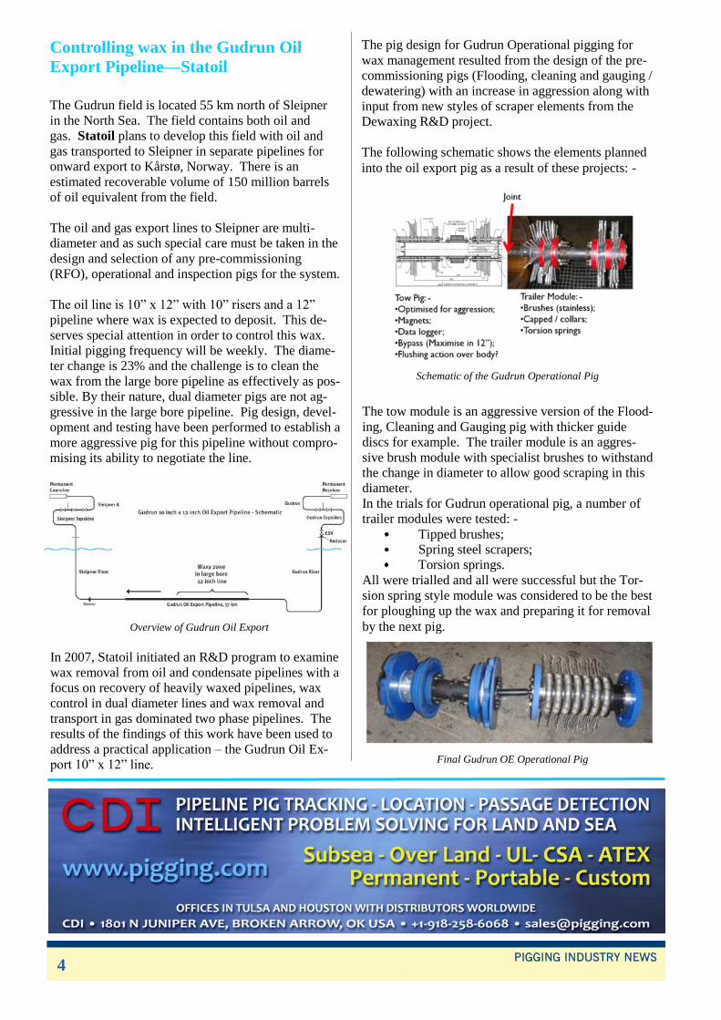
The following schematic shows the elements planned
into the oil export pig as a result of these projects: -
Schematic of the Gudrun Operational Pig
The tow module is an aggressive version of the Flood-
ing, Cleaning and Gauging pig with thicker guide
discs for example. The trailer module is an aggres-
sive brush module with specialist brushes to withstand
the change in diameter to allow good scraping in this
diameter.
In the trials for Gudrun operational pig, a number of
trailer modules were tested: -
Tipped brushes;
Spring steel scrapers;
Torsion springs.
All were trialled and all were successful but the Tor-
sion spring style module was considered to be the best
for ploughing up the wax and preparing it for removal
by the next pig.
Final Gudrun OE Operational Pig
4

The operation of the torsion springs are noted below.
By its very nature, a torsion spring is ideal for dual
diameter pigging in general as large angular
deflections can be accommodated (90, 180, even 270
degrees rotation). Pre-tension can be designed in,
thus maximising the force on the pipeline wall in the
large bore. The large deflection and small contact
area with the wax makes it ideal for any diameter
change and penetration of hard wax deposits: -
Action of the Torsion Springs
A torsion spring can have
angular deflections up to
270 degrees. This means
that they can be held in
tension and deflect
through 90 degrees from
one diameter pipe to an-
other.
The small contact area
means that the resulting
force can penetrate
through the wax to the
pipe wall thus ploughing
it up in preparation for the
next pig run.
Monitoring the Gudrun OE pigging would help to
provide valuable feedback on the success of this de-
sign. The aim is to try to keep the line clean for hy-
draulic efficiency but also for inspection of the line
every 5 years: -
There is a data logger provided for the Gudrun OE
pigs which can indicate the build up of wax in the
line (increased differential pressure, reduced vibra-
tion etc). It is planned to perform a base line run at
the start of the project and then follow this up with
other data logger runs two or three times per year.
This will help to establish the success of the Gudrun
pig aggression;
The ability of the pig bypass system (high area in
12” and low area in 10”) will be assessed. The pig
uses the 10” sealing discs to control bypass in the
small diameter line and higher bypass will be used
than would normally be possible. The pig is also
designed to flush wax off the body but this will only
be assessed on receipt of the pigs;
Action of torsion springs on a thick hard wax during trials
Although 6 mm of hard wax is
not expected to build up in the
line and the whole objective of
this development is to prevent
this, the tests were performed
on this worst case scenario to
see which technique would be
best at removing such a deposit.
The Torsion springs work by ploughing into hard wax
deposits and preparing them for removal by subse-
quent pigs run through the line. Population of the
trailer module with more and more springs can be
done to increase the aggression.
Two dewaxing Pig runs during tests (using data logger)
The graphs show data logger output during the initial
run to remove a short section of 6 mm thick hard wax
(top plot) and the second run (lower plot). The reduc-
tion in differential pressure over the hard wax zone
shows that the majority of the wax has been removed.
By comparing this to a base case run in the line it is
possible to monitor the pigs ability to control wax in
the line.
The maintenance requirements for these pigs can be
assessed based on the wear and tear on the various
components such as discs, springs and other
components.
For Gudrun it is planned to use the pig and data log-
ger to optimise the pigging frequency over time. This
could then also be applied to other dual diameter
waxy pipelines in the future and allow control of such
wax deposits. To do this will require good records
from Gudrun to establish if such an optimisation is
possible.
5

The unnoticed niche – Permanent Pigging A case study provided by JOERG LIS engineering
& project management.
Conventional heat exchangers require downtimes for
extensive cleaning resulting in production loss. A
corrugated cardboard factory was facing downtimes
of a plate heat exchanger often after only a few hours
use and at best it would last for five days. The new
heat exchanger system with a permanent cleaning sys-
tem by running pigs was developed and patented by
Jaske and Wolf GmbH an Energy & Water Solutions
company in Lingen, Germany. This is a great success
as no downtime is required anymore for cleaning.
Permanent pigging means that the pigs remain in the
pipeline systems and will frequently run as required,
e.g. every hour or every day.
Fig. 1: permanent cleaning pigs for different conditions.
Fig.: 2 pig stations (dark grey boxes), each station controls 4
pigs in 4 different pipelines
Conclusion: a permanent pig system is successfully
proven to be extreme efficient. This is a smart
solution for several purposes and many industries.
Joint ventures are being sought to enter the interna-
tional market and new fields of application.
The chart shows the efficiency over the first 23 days.
The system is successfully proven and has already
operated for over 25000 hours. Today, further heat
exchangers with permanent cleaning pigs are in
operation in several industries. The pig run intervals
can be adjusted as needed, e.g. regulated by
differential temperature. In this specific case, cleaning
pigs circulate every 30 minutes. The pigs remain in
the system and can be replaced quickly if required.
The DUPUR® heat exchanger with its permanent pig-
ging system is a suitable application for petrochemical
industry, food industry, biodiesel plants, paint indus-
try, thermal oil circuits in power distribution systems,
geothermal heat recovery from mine water (surface
brown coal mining) for buildings and more.
The advantages are:
No filter for pre-cleaning of the medium required
(high dirt contamination can be handled)
Surface cleaning within seconds
Cleaning intervals adjustable in accordance to the
level of debris
Intervals can be controlled by temperature
(automated control)
Heat transfer remains steady on a high level
Silt, crust formation, calcification and fouling in
heat exchangers is effectively avoided
No chemicals necessary for cleaning
Elimination of redundant replacement systems
and more
The lifetime of the pigs depends on the kind and
amount of debris. Some pigs were removed after 4
weeks. Other pigs have been running for over 3 years.
Debris will be removed automatically during
uninterrupted operation.
6

CPPI launches 40inch and 48inch
Tri-axial MFL inspection tools
China Petroleum Pipeline Inspection Technologies
Co.,Ltd (CPPI) has launched two new diameters of
its Tri-axial MFL inspection technology-40inch and
48inch. The new tools are equipped with Speed
Control System and Mapping Unit.
In late April 2013, the first Tri-axial MFL tool for
28-inch pipe made its debut in the Southwest Oil and
Gas Field pipe. The operator was pleased with the
process and results, and scheduled several additional
segments for inspection in the coming months. From
now on, operators of larger diameter pipelines can
also achieve the benefits from CPPI‟s new 40inch and
48inch tools.
CPPI has started the basic research of Tri-axial MFL
technology since 2009. Magnetic field is a three-
dimensional vector, using a cylindrical coordinate, the
vector can be divided into 3 components, axial, radial
and transverse. Compared with Uni-axial MFL
inspection, Tri-axial MFL inspection technology can
obtain more magnetic field distribution characteristics.
Probability of detection (POD), probability of identifi-
cation (POI) and sizing accuracy are enhanced
through a 13-in-1 sensor technology that incorporates
four main Hall Effect corrosion sensors oriented in
axial, radial and transverse vectors respectively,
combined with an eddy current sensor for internal/
external discrimination.
The 40inch and 48inch Tri-axial MFL inspection tools
will continue to assist pipeline operators in improving
pipeline integrity. The Tri-axial MFL inspection tools
is currently available in 20inch, 28inch, 40inch,
42inch and 48inch.
Second Queen’s Award for the Online
Electronics Group
Online Electronics Limited of Aberdeen the parent
company of business units in Houston, Dubai,
Singapore, Perth W.A. and specialist Online Valves
Limited has been awarded the most prestigious
Queen‟s Award for Enterprise 2014 for achieving
outstanding results in International Trade.
Recipients of the Award in 2008 the business is again
one of an elite group of companies that have been
recognised as deserving winners of the UK‟s highest
accolade for business success.
Founded in 1996 now with fifty employees, Online
Electronics, designs and manufactures pipeline pig
monitoring, pipeline data communication and logging
systems. It wins the Queen‟s Award 2014 Interna-
tional Trade for sustained growth in overseas export
earnings over the last five years, entering 30 new
markets in the period.
Managing Director Brian Gribble commented,
“Receiving the Queen‟s Award on a second occasion
is a great honour and an incredible achievement made
possible by the professional standard of work
delivered by all of our staff in Aberdeen and across all
of our overseas business units.”
CPPI launches 40” and 48” Tri-axial MFL inspection tool
7

Clock Spring Marker
Bands
Introduction
Pipelines require periodic
inspection to detect imperfec-
tions in the wall of the pipe
that could lead to subsequent
failure. Inspection is done by
several methods, the most
common of which is running
an inspection tool through the
pipe, known as in-line inspection.
These tools are designed to in-
spect the steel for imperfections
by use of various technologies
including, but not limited to, ultra-
sonic and magnetic flux
leakage (MFL). MFL is the most
common technology used for this
inspection task. It is valuable for a
pipeline operator to be able to
detect prior repairs on subsequent
inspection so that time is not spent
determining the disposition of a
defect detected by the inspection
equipment. The older more tradi-
tional repairs are identifiable in the
magnetic flux leakage inspection
tool data but the Clock Spring
composite repairs are invisible to
this technology due to their non-
metallic nature.
Clock Spring Marker Bands are
steel bands that are installed at each
end of the Clock Spring repair.
These bands are clearly detectable
by MFL inspection tools and they
indicate the position of a Clock
Spring repair. Figure 1 shows MFL
readings of two defects close to a
girth weld that have been repaired
with Clock Springs that had the
markers bands installed.
Figure 1. Detection of Marker Bands by MFL
tool. The Clock Spring is situated between the
two marker bands
The Design
The design of the marker band is
quite simple in principal but was a
result of considerable thought.
Clock Springs have been carefully
designed and it was important that
the marker bands did not affect or
modify the composition of the
composite material in anyway. The
elegant solution was to wrap a steel
band around the repair at each end
of the repair area. Research
conducted during the design of the
Clock Spring had already shown
that steel in contact with the outside
of the Clock Spring composite
caused no issues. Also installing
these bands would be a quick and
simple procedure.
Other methods to allow the repair
to be MFL tool detectable could
have been used. One of these was
to modify the structure of the
composite to include steel in its
makeup. This was not considered
by Clock Spring as a viable option.
Having a steel member sandwiched
within the composite causes a
number of potential long term per-
formance issues. The addition of
steel within the composite structure
reduces the ratio of glass to resin.
In a Clock Spring the ratio is
approximately 66% E glass to 33%
resin. This ratio was carefully de-
termined during the extensive long
term durability testing in the R&D
phase of the Clock Spring‟s devel-
opment. Significant reduction in the
E glass percentage causes a signifi-
cant reduction in the performance
and durability of the composite.
Also Steel has a very different
modulus to the E-glass that is used
in the manufacture of the compos-
ite. Continued stresses within the
repair would create the potential for
the resin/fibre matrix to separate
from the steel component. Not only
would this damage the composite it
would also create capillary paths
that would draw moisture into the
composite material. This moisture
would cause internal swelling
which would cause further damage
and create further capillary paths
for moisture ingress. The result
would be a runaway situation that
could seriously reduce the strength
of the repair in a relatively short
space of time. In addition to this
any moisture drawn in by capillary
action would cause the steel to rust.
Rust has a larger volume than steel
and this would mean an additional
mechanism of swelling within the
composite matrix.
Use in the Field
To date many thousands of Clock
Spring marker bands have been
installed and no evidence of any
reduction in performance of the
composite has come to light.
8

Figure 2 shows marker bands being
installed. Figure 3 shows the
marker bands installed over the
repair however, you will see in
Figure 2 that some operators prefer
to install the markers bands outside
of the repair area. This is an
acceptable method providing that
the marker bands are well insulated
from the pipe ensuring that metal to
metal contact is not possible. Both
methods of installation are in
accordance with Clock Spring‟s
documented literature.
Figure 2. Clock Spring Marker Bands being
installed
Figure 3. Clock Spring Marker Bands
installed as per standard procedure
Defect Shielding Caused by Steel
Markers The presence of steel acting as a
marker can shield the defect from
detection by the MFL tool. If steel
in some form was to be incorpo-
Figure 4: The Clock Spring Marker Bands
are seen along with a girth weld
Summary The design of the Clock Spring sys-
tem is the result of extensive testing
and validation. Clock Spring
Marker Bands are a method of al-
lowing MFL tool detection without
creating any deleterious effects to
the long term characteristics to the
Clock Spring repair. They have
been used extensively and have
been proven in service. Other meth-
ods of making a composite sleeve
MFL detectable are available.
However, any pipeline operators
considering such methods should
satisfy themselves that the marking
system will cause no detriment to
the repair.
For an installation video please
visit:
https://www.youtube.com/watch?
v=C_fsJenjrbo
rated into the composite structure
its location within the repair would
be fixed. The position of Clock
Spring Marker Bands can be ad-
justed to avoid shielding of the de-
fects. Having fixed markers can
lead to a situation where it is im-
possible not to have the marker
over the defect location. The defect
would then be shielded from future
MFL surveys.
NDT Global’s UT
inspection tool for crack
detection of 6" pipelines
NDT Global has announced the
commercial availability of
LineExplorer UC crack detection
Intelligent Inline Inspection (ILI)
tool for 6-inch pipelines.
The new ultrasonic ILI tool detects
and sizes axial cracks and crack-
like features such as fatigue cracks,
stress corrosion cracking (SCC) or
weld cracks.
Six-inch size pipelines are
predominantly used for the
transportation of refined products
as well as crude oil over relatively
short distances. The tool handles
inspection distances up to 80 km
and has 1.5D bend capability. Its in
-house designed sensor carrier is
equipped with 144 newly
developed crack inspection sensors
to secure optimum inspection data
quality.
Cracks and crack-like features can
appear during manufacturing, con-
struction and operational life of a
pipeline. Inline Inspection and sub-
sequent data analysis ensure early
detection of cracks thus preventing
pipeline failure which happens
when the crack dimension reaches a
material-specific critical size.
NDT Global's new 6-inch ultra-
sonic tool is a result of the
company's tool expansion program
and reflects the growing demand
for enhanced inline inspection data
accuracy and integrity services by
pipeline operators and owners.
9 9

US natural gas supplier
uses innovative inspection
technology from
3P Services
3P Services has created new
inspection tools for the US natural
gas supplier Pacific Gas and
Electric (PG&E). They have been
successfully deployed in their high
pressure gas pipeline system in late
February 2014.
The intelligent inspection tools, also
known as “smart PIGs”, are spe-
cially created for the 1m diameter
and 20km long pipeline which
includes extremely narrow bends.
The 1950s-vintage line also shows
diameter changes between 30” and
36”, and the tools will provide
PG&E with a highly detailed
analysis of the condition of their
pipelines.
The inspection tools collect
different kinds of parameters such
as geometric deformations, corro-
sion and metal loss. They use the
gas in the pipeline to make it travel,
which means there will be no
interruption of gas service.
“This is the first time in our his-
tory since the pipelines have been
installed that we‟ve launched an
inline inspection tool to assess the
integrity of our pipelines,” said
Sumeet Singh, PG&E‟s vice
president of assets and risk man-
agement in gas operations.
When the data is analyzed, PG&E
will have detailed information
about the pipeline that was
unobtainable before.
The inspection operations were
captured by various media such as
NBC, Bay Area TV and radio
reporters. This has a particular
reason. The inspected pipeline is
part of the natural gas distribution
system for the densely populated
peninsula between the Pacific
Ocean and San Francisco Bay.
That is where one of the most
serious US pipeline accidents
happened about 3 years ago. A
gas line section exploded in San
Bruno, south of San Francisco. 8
humans lost their lives and a fire
wall of 300m height destroyed
dozens of homes. The pipeline
operator, PG&E, sought for
modern inspection technologies
and met the specialists of 3P
Services of Lingen, Germany. A
contract was awarded to design,
build and test the inspection tools
two years ago.
After the PG&E representatives
have approved the inspection de-
vices in last winter, it was time to
run the special tools in the pipe-
line under real conditions. It has
been a success and 3P Services is
looking forward to inspecting
more “unpiggable” pipelines for
PG&E.
New software helps
operators manage
pressure cycle fatigue
analysis in aging pipelines
Quest Integrity Group recently
released Pacifica™, a new software
solution to perform pressure cycle
fatigue analysis on seam crack
flaws in pipelines.
In aging pipelines, failures can
occur after long run times due to an
accumulation of pressure cycles.
Since the safety and environmental
consequences of a pipeline failure
are highly significant, Quest Integ-
rity Group developed Pacifica to
help operators manage the cyclic
fatigue on their pipelines. Based on
the American Petroleum Institute‟s
advanced Fracture Mechanics
methodology, this software solution
helps operators meet regulatory
expectations, observe best prac-
tices, and effectively manage the
risk of failure due to pressure cycle
fatigue. In addition, this
solution increases the information
yield from operators‟ existing
investments in SCADA systems
and on-line monitoring sensors.
Fatigue growth analysis is
performed using actual pressure
data for real-time monitoring, while
hydraulic modeling determines true
pressure loading at crack locations
throughout the pipeline for accurate
growth predictions. Pacifica also
uses a database structure to store
pressure data for future analysis.
With the support of Quest Integrity
engineers, the analysis data guides
prioritization of anomaly investiga-
tions, hydrotest and in-line inspec-
tion schedules, material property
testing requirements and evaluation
10
of the impact of operations on seam
weld integrity.
Pacifica adds to Quest Integrity‟s
advanced analytics solution set
focusing on pipeline integrity
management. Pipeline operators
can now accurately model crack
fatigue growth in pipelines, set
re-inspection schedules, prioritize
anomaly investigations and
enhance their overall program by
utilizing this new software.

Innospection Ltd’s subsea
riser scanner MEC-
MPS200+ demonstrates
superior defect detection
A successful defect detection
verification trial of the external
SLOFEC based subsea riser
scanning system, MEC-MPS200+,
was performed on coated heavy-
walled steel riser pipe samples by
Innospection for an Operator in the
Gulf of Mexico.
The 6”, 8” and 20” riser test
samples with wall thickness up to
ROSEN introduces new
ATEX Certified EPD
device
To localize and track inspection or
cleaning tools during their run, they
are usually either equipped with an
ITX Transmitter or with strong
magnets, whose fields penetrate the
pipe wall or magnetize it. The
signals of the ITX Transmitter or
the magnetic fields can be received
by a receiver outside the pipeline.
ROSEN has now developed a new
generation of ATEX certified
instruments for tool localization at
its Research and Technology Cen-
ter in Lingen, Germany.
Today ATEX certification is an
essential requirement if a product is
to be used in potentially explosive
atmospheres. The certification must
be provided by a recognized certifi-
cation body.
These bodies check and verify on
the one hand, whether the design is
in compliance with current stan-
dards. On the other hand, statutory
tests are performed. The ROSEN
ATEX EPD (EPD - Electronic Tool
Detector) has this assessment and
all tests were successfully com-
pleted and documented by a EC-
Certificate of Conformity.
The new ATEX EPD combines
essential features of previous re-
ceivers. In addition, the partially
very weak electromagnetic fields
can be displayed on an LCD dis-
play with the ATEX EPD, improv-
ing the readability of the received
signals significantly. The new
ATEX EPD with carrier
The following list summarizes the
key features of the new ATEX
EPD:
ITX Transmitter Locating
ITX and MFL Tracking
Yoke Detection
ATEX and IEC Ex Compliance
Graphic LCD Display, GPS,
Bluetooth
The first devices were already
successfully used in Mexico and
Colombia and customers are
showing great interest.
New multi-million pound
offices for IKM Testing
(UK) Ltd IKM Testing (UK) Ltd is investing
in a new multi-million pound
facility for its pipeline and process
operations. The £3.82 million
purpose-built facility, located in
Westhill Business Park near
Aberdeen, UK, will provide a
22,500sq ft base for IKM„s
11
ATEX EPD is a completely revised
and expanded device. Aberdeen International Division
headquarters.
Mark Rasmusen, director of IKM‟s
International Division, said the firm
was going to have an exciting 2014.
He said: “We have outgrown our
old office and workshop/yard in
recent years as we‟ve considerably
expanded our operations.
“The new high specification build-
ing will allow us to continue our
growth and provide us with a
purpose-built facility with a larger
office, workshop and yard space
incorporating a training facility
and designated test bay.
“The move will allow us to consoli-
date our existing properties in
Aberdeen in an easily accessible
location, which will make us more
streamlined and allow a bigger
work capacity, and also shows our
commitment to the UK market, not
just to clients but also to our
employees.

Signals display showing detectability down from 10% wall loss
onwards for Ø10mm and Ø20mm internal defects on 6” coated
riser sample
12
1” and external Splashtron coating of 12.7mm were
the subject of the verification trial. Artificial 10mm
and 20mm external and internal defects with wall loss
varying from 5% to 80% were machined onto the
coated riser samples. The target of the verification
trial was to show the defect detection capabilities of
the SLOFEC technique on external and internal
defects having a wall loss of at least 10%.
The full detectability down to 10% wall loss was
achieved for both the 10mm external and internal
defect on all three coated pipe samples. In addition,
this target was exceeded as the MEC-MPS200+
scanner was able to detect the 20mm external defects
having a wall loss of 5% on all three coated pipe
samples. This demonstrated the superior detection
capability of the SLOFEC technique despite the fairly
thick pipe coating.
In conclusion, the quality of the obtained test data was
good and the artificial defects were classified as well
detectable when the corresponding Eddy Current
signals show a signal-to-background ratio of 6 dB and
higher. The ratio between the pipe wall thickness and
coating thickness showed relevance to the field
penetration and detection capability.
Although the MEC-MPS200+ scanner is configured
for inspecting comparable pipe wall thickness and
coating thickness as in this verification trial, some
other tests performed have shown additional
inspection capabilities of the SLOFEC technique with
additional induced field strength.
With the completion of this verification trial, a
mobilisation to perform an external inspection of five
coated hull risers on a platform in the Gulf of Mexico
will follow shortly.