FUKUDA Storage Battery Co.fukuda.com.sg/wp-content/uploads/2015/11/kpx.pdf · battery, the positive...
17
FUKUDA ® Nickel Cadmium Batteries are designed and manufactured for the requirements of high reliability where risk of failure is unacceptable. With a comprehensive range of cells, FUKUDA ® KPX range of Nickel Cadmium Batteries are the best choice to meet the modern industries’ rigorous rang of operating conditions! APPLICATIONS • Petrochemical Industry • Fire & Security systems • Process Control systems • Telecommunications • Mass Transits systems • Emergency lighting • Railway signaling • Switchgears BENEFITS • Wide range of operating temperatures • Resistant to Mechanical and Electrical abuses • Excellent performance, high energy storage • Designed life of up to 20 years • Complete reliability, no sudden deaths • Simple maintenance • High charging rate acceptable • Low installation cost FUKUDA STORAGE BATTERY CO., LTD
Transcript of FUKUDA Storage Battery Co.fukuda.com.sg/wp-content/uploads/2015/11/kpx.pdf · battery, the positive...

FUKUDA® Nickel Cadmium Batteries are designed and manufactured for the requirements of high reliability where risk of failure is unacceptable.
With a comprehensive range of cells, FUKUDA® KPX range of Nickel Cadmium Batteries are the best choice to meet the modern industries’ rigorous rang of operating conditions!
FUKUDA® Storage Battery Co.
APPLICATIONS
• Petrochemical Industry
• Fire & Security systems
• Process Control systems
• Telecommunications
• Mass Transits systems
• Emergency lighting
• Railway signaling
• Switchgears
BENEFITS
• Wide range of operating temperatures • Resistant to Mechanical and Electrical abuses • Excellent performance, high energy storage • Designed life of up to 20 years
• Complete reliability, no sudden deaths • Simple maintenance • High charging rate acceptable • Low installation cost
FUKUDA STORAGE BATTERY CO., LTD
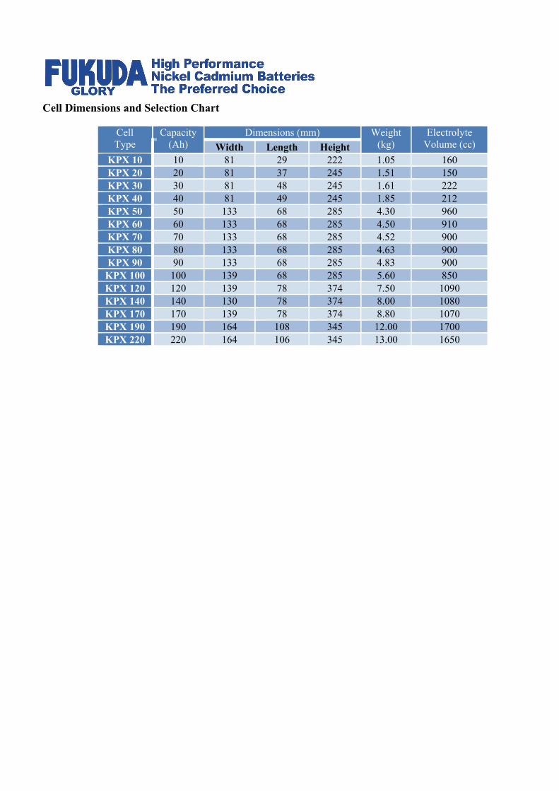
Cell Dimensions and Selection Chart
Cell Type
Capacity (Ah)
Dimensions (mm) Weight (kg)
Electrolyte Volume (cc) Width Length Height
KPX 10 10 81 29 222 1.05 160 KPX 20 20 81 37 245 1.51 150 KPX 30 30 81 48 245 1.61 222 KPX 40 40 81 49 245 1.85 212 KPX 50 50 133 68 285 4.30 960 KPX 60 60 133 68 285 4.50 910 KPX 70 70 133 68 285 4.52 900 KPX 80 80 133 68 285 4.63 900 KPX 90 90 133 68 285 4.83 900
KPX 100 100 139 68 285 5.60 850 KPX 120 120 139 78 374 7.50 1090 KPX 140 140 130 78 374 8.00 1080 KPX 170 170 139 78 374 8.80 1070 KPX 190 190 164 108 345 12.00 1700 KPX 220 220 164 106 345 13.00 1650

PERFORMANCE CHARACTERISTICS
FOR FUKUDA
NICKEL CADMIUM BATTERY
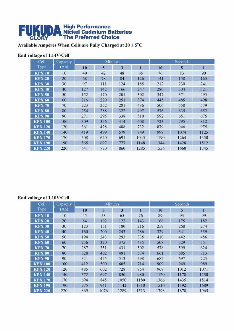
Available Amperes When Cells are Fully Charged at 20 ± 5oC
End voltage of 1.14V/Cell Cell Type
Capacity (Ah)
Minutes Seconds 10 5 3 1 10 5 1
KPX 10 10 40 42 48 65 76 83 90 KPX 20 20 68 78 84 126 141 158 165 KPX 30 30 97 111 124 185 212 230 241 KPX 40 40 127 142 166 247 280 304 321 KPX 50 50 152 170 201 302 347 371 495 KPX 60 60 216 229 251 374 445 485 498 KPX 70 70 223 252 281 436 506 558 579 KPX 80 80 254 288 322 497 576 635 652 KPX 90 90 271 295 338 510 592 651 675
KPX 100 100 309 356 414 608 723 795 812 KPX 120 120 361 428 488 732 879 946 975 KPX 140 140 419 499 579 849 998 1074 1125 KPX 170 170 508 620 691 1045 1190 1264 1350 KPX 190 190 565 697 777 1148 1344 1428 1512 KPX 220 220 641 770 860 1285 1556 1660 1745
End voltage of 1.10V/Cell
Cell Type
Capacity (Ah)
Minutes Seconds 10 5 3 1 10 5 1
KPX 10 10 45 53 65 76 89 93 99 KPX 20 20 84 102 122 143 168 175 182 KPX 30 30 123 151 180 216 259 268 274 KPX 40 40 160 200 243 286 329 341 359 KPX 50 50 194 243 293 335 410 442 456 KPX 60 60 256 320 375 435 508 529 551 KPX 70 70 287 351 431 502 578 599 624 KPX 80 80 328 402 491 574 661 685 713 KPX 90 90 341 425 513 598 682 697 725
KPX 100 100 412 500 605 714 909 949 989 KPX 120 120 485 602 728 854 968 1012 1071 KPX 140 140 572 697 850 980 1120 1178 1250 KPX 170 170 694 845 1050 1180 1366 1435 1514 KPX 190 190 775 941 1142 1310 1510 1592 1689 KPX 220 220 869 1076 1289 1513 1798 1878 1965

Available Amperes When Cells are Fully Charged at 20 ± 5oC
End voltage of 1.05V/Cell Cell Type
Capacity (Ah)
Minutes Seconds 10 5 3 1 10 5 1
KPX 10 10 48 66 85 109 131 143 154 KPX 20 20 92 128 161 210 256 275 302 KPX 30 30 136 188 238 305 380 411 458 KPX 40 40 185 241 311 401 520 564 603 KPX 50 50 221 295 397 496 652 706 746 KPX 60 60 278 375 451 600 802 866 920 KPX 70 70 322 427 517 693 887 963 1060 KPX 80 80 368 489 591 765 1014 1101 1205 KPX 90 90 394 502 621 813 1090 1156 1254
KPX 100 100 450 610 779 992 1302 1412 1501 KPX 120 120 540 711 920 1189 1580 1701 1797 KPX 140 140 630 820 998 1380 1725 1968 2075 KPX 170 170 758 1002 1171 1670 2170 2345 1489 KPX 190 190 850 1120 1338 1850 2460 2656 2812 KPX 220 220 984 1250 1488 2130 2804 3014 3275
End voltage of 1.00V/Cell
Cell Type
Capacity (Ah)
Minutes Seconds 10 5 3 1 10 5 1
KPX 10 10 51 82 102 121 184 198 201 KPX 20 20 100 162 201 240 360 389 401 KPX 30 30 153 243 298 355 533 567 599 KPX 40 40 199 318 389 463 710 750 789 KPX 50 50 243 395 473 587 879 927 984 KPX 60 60 302 460 587 705 1088 1123 1178 KPX 70 70 347 521 681 772 1253 1311 1362 KPX 80 80 400 600 780 889 1423 1498 1560 KPX 90 90 431 642 802 904 1521 1597 1674
KPX 100 100 501 788 950 1102 1798 1880 1967 KPX 120 120 606 931 1125 1255 2178 2250 2321 KPX 140 140 698 1012 1311 1460 2513 2610 2701 KPX 170 170 845 1189 1609 1783 3095 3196 3289 KPX 190 190 943 1350 1799 1950 3378 3455 3556 KPX 220 220 1098 1500 1987 2204 3710 3809 3989

Available Amperes When Cells are Fully Charged at 20 ± 5oC
End voltage of 0.85 V/Cell Cell Type
Capacity (Ah)
Minutes Seconds 10 5 3 90 60 30 10 5 1
KPX 10 10 56 98 115 140 190 205 215 347 250 KPX 20 20 105 162 221 260 360 390 420 480 500 KPX 30 30 167 324 367 420 530 570 611 650 689 KPX 40 40 209 371 470 560 700 760 809 876 897 KPX 50 50 250 420 590 700 880 940 1007 1134 1190 KPX 60 60 330 480 730 840 1140 1240 1300 1400 1499 KPX 70 70 394 592 840 980 1197 1330 1400 1501 1621 KPX 80 80 450 610 970 1140 1280 1390 1520 1660 1730 KPX 90 90 478 629 1050 1190 1294 1410 1527 1680 1756
KPX 100 100 530 805 1147 1330 1600 1930 1854 2000 2106 KPX 120 120 660 966 1380 1580 2100 2260 2389 2510 2800 KPX 140 140 780 1160 1680 1824 2400 2580 2710 2900 3012 KPX 170 170 920 1420 1874 2220 2800 3110 3250 3490 3601 KPX 190 190 1000 1508 2001 2510 3000 3300 3501 3667 3723 KPX 220 220 1200 1700 2300 2860 3500 3640 3809 4100 4206
End voltage of 0.65V/Cell
Cell Type
Capacity (Ah)
Minutes Seconds 10 5 3 90 60 30 10 5 1
KPX 10 10 55 106 123 156 215 240 310 370 410 KPX 20 20 121 203 238 290 420 468 606 720 800 KPX 30 30 185 315 390 460 617 690 908 1039 1150 KPX 40 40 240 396 505 610 821 930 1207 1408 1500 KPX 50 50 298 490 580 800 1034 1150 1480 1740 1870 KPX 60 60 371 600 814 1010 1310 1460 1750 1997 2209 KPX 70 70 410 689 908 1120 1465 1610 2010 2150 2405 KPX 80 80 483 755 1150 1280 1697 1850 2107 2400 2601 KPX 90 90 510 840 1190 1320 1785 1990 2304 2447 2808
KPX 100 100 600 947 1321 1600 2110 2300 3004 3401 3705 KPX 120 120 720 1122 1610 1920 2479 2620 3210 3885 4209 KPX 140 140 845 1301 1730 2240 2900 3210 3605 3981 4398 KPX 170 170 1105 1502 1980 2720 3300 3700 4209 4001 4948 KPX 190 190 1201 1690 2080 2900 3457 3900 4318 4827 5188 KPX 220 220 1390 1800 2450 3300 4003 4300 4857 5010 5800

OPERATION & MAINTENANCE
MANUAL FOR FUKUDA
NICKEL CADMIUM BATTERY
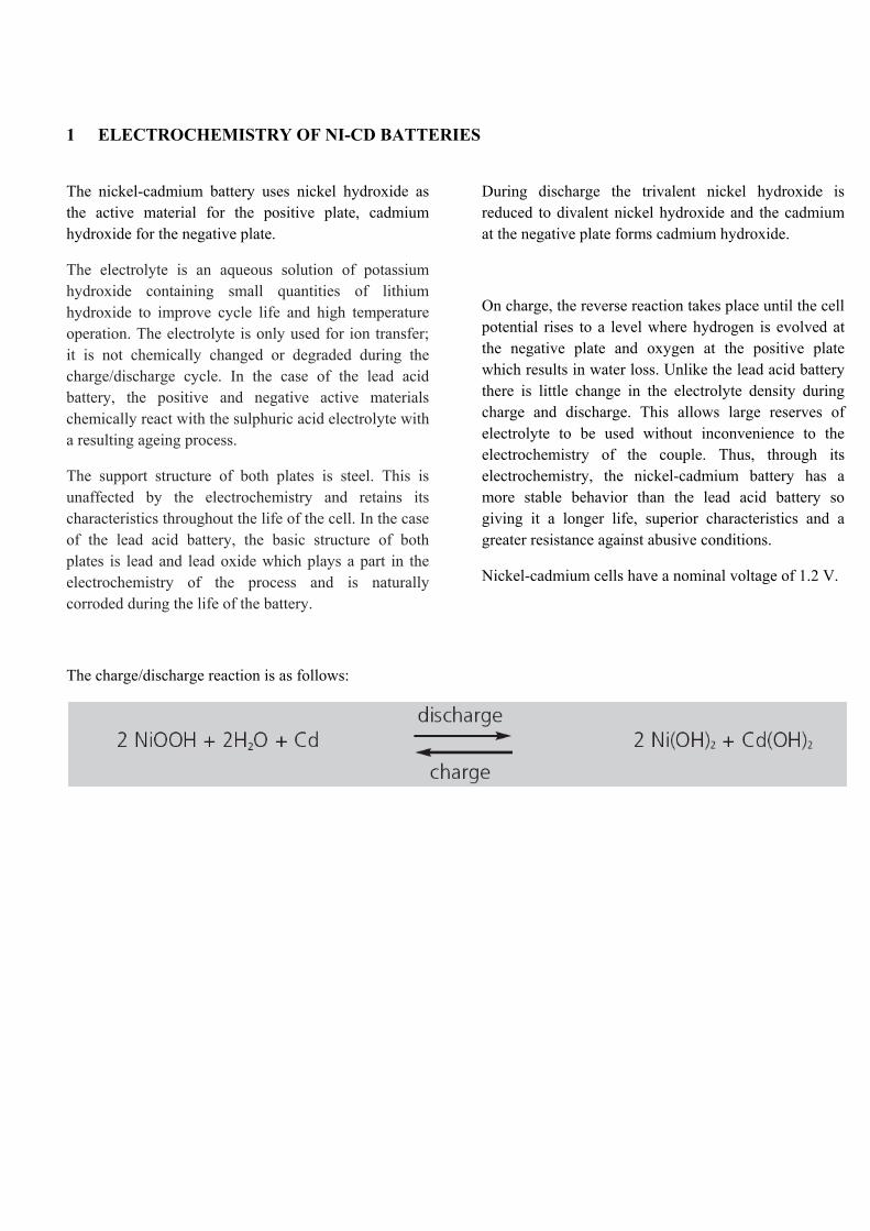
1 ELECTROCHEMISTRY OF NI-CD BATTERIES
The nickel-cadmium battery uses nickel hydroxide as the active material for the positive plate, cadmium hydroxide for the negative plate.
The electrolyte is an aqueous solution of potassium hydroxide containing small quantities of lithium hydroxide to improve cycle life and high temperature operation. The electrolyte is only used for ion transfer; it is not chemically changed or degraded during the charge/discharge cycle. In the case of the lead acid battery, the positive and negative active materials chemically react with the sulphuric acid electrolyte with a resulting ageing process.
The support structure of both plates is steel. This is unaffected by the electrochemistry and retains its characteristics throughout the life of the cell. In the case of the lead acid battery, the basic structure of both plates is lead and lead oxide which plays a part in the electrochemistry of the process and is naturally corroded during the life of the battery.
During discharge the trivalent nickel hydroxide is reduced to divalent nickel hydroxide and the cadmium at the negative plate forms cadmium hydroxide.
On charge, the reverse reaction takes place until the cell potential rises to a level where hydrogen is evolved at the negative plate and oxygen at the positive plate which results in water loss. Unlike the lead acid battery there is little change in the electrolyte density during charge and discharge. This allows large reserves of electrolyte to be used without inconvenience to the electrochemistry of the couple. Thus, through its electrochemistry, the nickel-cadmium battery has a more stable behavior than the lead acid battery so giving it a longer life, superior characteristics and a greater resistance against abusive conditions.
Nickel-cadmium cells have a nominal voltage of 1.2 V.
The charge/discharge reaction is as follows:

2 CONSTRUCTION FEATURES OF KPX BATTERIES
2.1 Positive Plate
The positive plate used in the cell is of the sintered type. This is obtained by chemical impregnation of nickel hydroxide into a porous nickel structure, which is obtained by sintering nickel powder into a thin, perforated, nickel-plated strip.
2.2 Negative Plate
The negative electrode is a plastic-bonded cadmium electrode, produced with a continuous process. This involves blending together the active material, binder and additives, continuously spreading this onto a perforated nickel-plated steel substrate, drying and, finally, passing the coated band through rollers for dimensioning.
2.3 Plate Tab
The electrodes are seam welded to the plate tabs so producing a continuous interface between the two components. This ensures high current transfer and maximum strength. The plate tab material is nickel-plated steel and the plate tab thickness is chosen to ensure a satisfactory current carrying capability consistent with the application.
2.4 Separator
The separator consists of a sandwich of micro-porous polymer and non-woven felt which maintains an optimised distance between the electrodes. The separator system has been developed to give an optimum balance between performance, reliability and long life.
2.5 Terminal Pillars
The material used for the terminal pillars (copper or steel) and the number of terminals per cell are chosen as a function of the intended application. The terminal pillars are nickel-plated.
2.6 Electrolyte
The electrolyte used is a solution of potassium hydroxide and lithium hydroxide, is optimised to give the best combination of performance, life, energy efficiency and a wide temperature range.
The concentration of the standard electrolyte is such as to allow the cell to be operated down to temperature extremes as low as –20°C and as high as +50°C. This allows the very high temperature fluctuation found in certain regions to be accommodated.
For very low temperatures a special high density electrolyte can be used. It is an important consideration for all nickel-cadmium batteries that the electrolyte concentration does not change during charge and discharge. It retains its ability to transfer ions between the cell plates, irrespective of the charge level. In most applications, the electrolyte will retain its effectiveness for the life of the battery and will never need replacing.
The electrode material is less reactive with the alkaline electrolyte (nickel-cadmium secondary batteries) than with acid electrolytes (lead acid secondary batteries). Furthermore, during charging and discharging in alkaline batteries the electrolyte works mainly as a carrier of oxygen or hydroxyl ions from one electrode to the other, hence the composition or the concentration of the electrolyte does not change noticeably. In the charge/discharge reaction of the nickel-cadmium battery, the potassium hydroxide is not mentioned in the reaction formula. A small amount of water is produced during the charging procedure (and consumed during the discharge). The amount is not enough to make it possible to detect if the battery is charged or discharged by measuring the density of the electrolyte.
Once the battery has been filled with the correct electrolyte at the battery factory, there is no need to check the electrolyte density periodically. The density of the electrolyte in the battery either increases or decreases as the electrolyte level drops because of water electrolysis or evaporation or rises at topping-up.
Interpretation of density measurements is difficult and could be misleading.

3 OPERATING FEATURES
3.1 Capacity
The electrical capacity is rated in ampere-hours (Ah) and is the quantity of electricity at 20°C which it can supply for a 5 hour discharge to 1.0 V after being fully charged at 7.5 hours at 0.2 C5 A. This figure is in agreement with the IEC 60623 standard.
3.2 Cell Voltage
The cell voltage of nickel-cadmium cells results from the electrochemical potentials of the nickel and the cadmium active materials in the presence of the potassium hydroxide electrolyte. The nominal voltage for this electrochemical couple is 1.2 V.
3.3 Internal Resistance
The internal resistance of a cell varies with the type of service and the state of charge and is, therefore, difficult to define and measure accurately.
The most practical value for normal applications is the discharge voltage response to a change in discharge current.
For cells 50% discharged, the internal resistance is about 20% higher, and when 90% discharged it is about 80% higher. The internal resistance of a fully discharged cell has very little meaning.
Reducing the temperature also increases the internal resistance and, at 0°C, the internal resistance is about 15% higher.
3.4 Effect of Temperature on Performance
Variations in ambient temperature affect the performance of the battery and these are planned for.
Low temperature operation has the effect of reducing the performance but the higher temperature characteristics are similar to those at normal temperatures. The effect of temperature is more marked at higher rates of discharge.
The factors which are required in sizing a battery to compensate for temperature variations are given in a graphical form in Figure 1 for an operating temperature range of –20°Cto + 40°C.
Figure 1 : Temperature de-rating factor for different rate discharge
3.5 Effect of Temperature on Lifetime
The batteries are designed as a twenty year life product but, as with every battery system, increasing temperature reduces the expected life.
However, the reduction in lifetime with increasing temperature is very much lower for the nickel-cadmium battery than the lead acid battery.
The reduction in lifetime for the nickel-cadmium battery and, for comparison, a high quality lead acid battery is shown graphically in Figure 2
Figure 2 : Effect of temperature on lifetime

4 BATTERY CHARGING
4.1 Constant Voltage Charging Method
Batteries in stationary applications are normally charged by a constant voltage float system and this can be two types: the two-rate type where there is an initial constant voltage charge followed by a lower floating voltage, or a single rate floating voltage
The single voltage charger is necessarily a compromise between a voltage high enough to give an acceptable charge time and low enough to give a low water usage. However it does give a simpler charging system and accepts a smaller voltage window than the two-rate charger.
The two-rate charger has an initial high voltage stage to charge the battery followed by a lower voltage maintenance charge. This allows the battery to be charged quickly, and yet, have low water consumption due to the low voltage maintenance level.
For float applications, the values used for Ni-Cd Batteries for single and two-rate charge systems are:
• Single rate charge: 1.41 ± 0.01 V/cell at +20°C • Dual rate charge:
High rate: 1.45 ± 0.01 V/cell at +20°C Float charge: 1.40 ± 0.01 V/cell at +20°C
In case of frequent cycling, the recommended charge voltages are:
• Single rate charge: 1.45 - 1.55 V/cell at +20°C
• Dual rate charge: High rate: 1.45 - 1.60 V/cell at +20°C Float charge: 1.40 ± 0.01 V/cell at +20°C
To minimise the water usage, it is important to use a low charge voltage, and so the minimum voltage for the single level and the two level charge voltage is the normally recommended value. This also helps within a voltage window to obtain the lowest, and most effective, end of discharge voltage.
4.2 Charge Acceptance
A discharged cell will take a certain time to achieve a full state of charge.
Figure 3 gives the capacity available for typical charging voltages recommended for the XHP range during the first 24 hours of charge from a fully discharged state.
This graph gives the recharge time for a current limit of 0.2 C5 A. Clearly, if a lower value for the current is used, e.g. 0.1 C5 A, then the battery will take longer to charge.
If a higher current is used then it will charge more rapidly. This is not in general a pro rata relationship due to the limited charging voltage.
If the application has a particular recharge time requirement then this must be taken into account when calculating the battery.
Figure 3 : Available capacity for typical charging voltages

4.3 Charge Efficiency
The charge efficiency of the battery is dependent on the state of charge of the battery and the temperature. For much of its charge profile, it is recharged at a high level of efficiency.
In general, at states of charge less than 80% the charge efficiency remains high, but as the battery approaches a fully charged condition, the charging efficiency falls off. This is illustrated graphically in Figure 7.
4.4 Temperature Effects
As the temperature increases, the electrochemical behavior becomes more active, and so for the same floating voltage, the current increases. As the temperature is reduced then the reverse occurs. Increasing the current increases the water loss, and reducing the current creates the risk that the cell will not be sufficiently charged. For standby application, it is normally not required to compensate the charging voltage with the temperature. However if water consumption is of main concern, temperature
compensation should be used if the battery is operating at high temperature such as +35ºC. At low temperature (<0ºC), there is a risk of poor charging and it is recommended to adjust the charging voltage or to compensate the charging voltage with the temperature.
Value of the temperature compensation: – 2 mV/ºC, starting from an ambient temperature of 20ºC to 25ºC
Figure 4 : Charge efficiency as a function of state of charge
5 INSTALLATION AND OPERATING INSTRUCTIONS
Important Recommendations
• Never allow an exposed flame or spark near the battery, particularly while charging.
• Never smoke while performing any operation on the battery.
• For protection, wear rubber gloves, long sleeves, and appropriate splash goggles or face shield.
• The electrolyte is harmful to skin and eyes. In the event of contact with skin or eyes, wash immediately with plenty of water. If eyes are affected, flush with water, and obtain immediate medical attention.
• Remove all rings, watches and other items with metal parts before working on the battery.
• Use insulated tools.
• Avoid static electricity and take measures for protection against electric shocks.
• Discharge any possible static electricity from clothing and/or tools by touching an earth - connected part “ground” before working on the battery.
5.1 Receiving the shipment
Unpack the battery immediately upon arrival. Do not overturn the package. Transport seals are located under the cover of the vent plug.
The battery is normally shipped filled, discharged and ready for installation
The battery must never be charged with the plastic transport seals in place as this can cause permanent damage.
5.2 Storage
Store the battery indoors in a dry, clean and cool (0°C to +30°C) location.
• Do not store in unopened packing crates. The lid and the packing material on top of the cells must be removed.
• Make sure that the transport seals remain in place during storage.
•
• Do not store in direct sunlight or exposed to excessive heat.
• A battery delivered discharged and filled may be stored for many years before it is installed.
• A battery delivered exceptionally 80% charged (for starting application) must not be stored for more than 3 months (including transport).
5.3 Installation
5.3.1 Location Install the battery in a dry and clean room. Avoid direct sunlight, strong daylight and heat.
The battery will give the best performances and maximum service life when the ambient temperature is between 10°C to 30°C.
The batteries can be fitted on to stands, floor-mounted or fitted into cabinets.
Local standards or codes normally define the mounting arrangements of batteries, and these must be followed if applicable. However, if this is not the case, the following comments should be used as a guide.
When mounting the battery, it is desirable to maintain an easy access to all cells; they should be situated in a readily available position.
Distances between stands, and between stands and walls, should be sufficient to give good access to the battery.
The overall weight of the battery must be considered and the load bearing on the floor taken into account in the selection of the battery accommodation.
If the battery is enclosed in a cabinet or other such enclosed space, it is important to provide sufficient space to disperse the gases given off during charging, and also to minimise condensation.
It is recommended that at least 200 mm be allowed above cell tops, to ensure easy access during inspection and water replenishment, and that enough space is allowed between cabinet walls and the battery to avoid any risk of short-circuits. Flip-top vents may be turned through 180° to achieve the most convenient position for water replenishment.
5.3.2 Ventilation Note that special regulations for ventilation may be valid in your area depending on the application.
When the battery is housed in a cubicle or enclosed compartment, it is necessary to provide adequate ventilation.
During the last part of high-rate charging, the battery is emitting gases (oxygen and hydrogen mixture).
If it is required to establish that the ventilation of the battery room is adequate, then it is necessary to calculate the rate of evolution of hydrogen to ensure that the concentration of hydrogen gas in the room is kept within safe limits.
The theoretical safe limit for hydrogen concentration is 4%. However, some standards call for more severe levels than this, and levels as low as 1% are sometimes required.
To calculate the ventilation requirements of a battery room, the following method can be used:
1 Ah of overcharge breaks down 0.366 cm3 of water, and 1 cm3 of water produces 1.865 litres of gas in the proportion 2/3 hydrogen and 1/3 oxygen. Thus 1 Ah of overcharge produces 0.42 litres of hydrogen.
Therefore, the volume of hydrogen evolved from a battery per hour
= number of cells x charge current x 0.42 litres (0.00042 m3)
The volume of hydrogen found by this calculation can be expressed as a percentage of the total volume of the battery room, and from this, the number of air changes required to keep the concentration of hydrogen below a certain level can be calculated.
5.3.3 Electrolyte The electrolyte to be used is: E4.
When checking the electrolyte levels, a fluctuation in level between cells is not abnormal and is due to the different amounts of gas held in the separator of each cell. The level should be at least 15 mm above the minimum mark and there is normally no need to adjust it.
When the cells are charged, the electrolyte level can be above the high level mark.
5.4 Commissioning
Verify that the ventilation is adequate during this operation.
• For filled and discharged cells stored up to 1 year, a commissioning charge is normally not required and the cells are ready for immediate use. If full performances are necessary immediately, a commissioning charge is recommended as mentioned in the section below.
• For cells stored more than 1 year, a commissioning charge is necessary. A constant current charge is preferable: 8 h at 0.2 C5 A.
• When the charger maximum voltage setting is too low to supply constant current charging, divide the battery into two parts to be charged individually.
• Constant potential charge: 1.50 V/cell minimum.
Charging time: 24 h if the charging current is limited to 0.2 C5 A, 48 h if the charging current is limited to 0.1 C5 A.
Please note: if cells have been stored in charged conditions for more than 3 months (including transport), or if cells have been stored for a few years or show difficulties in recovering performance, constant current charging becomes necessary and the following values are recommended:
a) 15 h charge at 0.2 C5 A
b) discharge at 0.2 C5 A down to 1.0 V/cell
c) 8h charge at 0.2 C5 A
d) the battery is ready for use.
5.5 Charging in service
At continuous parallel operation, the battery is on continuous charge and has only occasional discharges.
Recommended charging voltage at ambient temperatures:
• for dual charge level:
Float level: 1.40 ± 0.01 V/cell High level: 1.45 ± 0.01 V/cell
• for single charge level:
1.41 ± 0.01 V/cell For use at temperature outside ambient temperatures, the correcting factor for charge voltage is –2 mV/°C/cell.
5.6 Periodic maintenance
• Keep the battery clean using only water. Do not use a wire brush or solvents of any kind. Vent caps can be rinsed in clean water if necessary.
• Check visually the electrolyte level. Never let the level fall below the minimum level mark. Use only distilled or deionized water to top-up. Experience will tell the time interval between topping-up. Note: Once the battery has been filled with the correct electrolyte at the battery factory, there is no need to check the electrolyte density periodically. Interpretation of density measurements is difficult and could be misleading.
• Check every two years that all connectors are tight. The connectors and terminal nuts should be corrosion-protected by coating with neutral vaseline.
• Check the charging voltage. It is important that the recommended charging voltage remains unchanged. The charger should be checked at least once a year. High water consumption of the battery is usually caused by improper voltage setting of the charger.
5.7 Charging electrolyte
Due to the sintered electrode plastic-bonded technology, it is not necessary to change the electrolyte during the lifetime of the cell.

6 MAINTAINING THE BATTERIES IN SERVICE
In a correctly designed standby application, the batteries require the minimum of attention. However, it is good practice with any system to carry out an inspection at least once a year, or at the recommended water replenishment interval period, to ensure that the charger, the battery and the auxiliary electronics are all functioning correctly.
When this inspection has been done, it is recommended that certain procedures should be carried out to ensure that the battery is maintained in a good state.
6.1 Cleanliness/mechanical
Cells must be kept clean and dry at all times, as dust and damp cause current leakage. Terminals and connectors should be kept clean, and any spillage during maintenance should be wiped off with a clean cloth. The battery can be cleaned, using water. Do not use a wire brush or a solvent of any kind. Vent caps can be rinsed in clean water, if necessary.
Check that the vents are tightly fitted and that there are no deposits on the vent cap.
Terminals should be checked for tightness, and the terminals and connectors should be corrosion-protected by coating with a thin layer of neutral grease or anti-corrosion oil.
6.2 Water replenishment
Check the electrolyte level. Never let the level fall below the lower MIN mark. Use only approved distilled or deionized water to replenish. Do not however, overfill the cells.
Excessive consumption of water indicates operation at too high a voltage or too high a temperature. Negligible consumption of water, with batteries on continuous low current or float charge, could indicate under-charging. A reasonable consumption of water is the best indication that a battery is being operated under the correct conditions. Any marked change in the rate of water consumption should be investigated immediately. It is recommended that, initially, electrolyte levels should be monitored monthly to determine the frequency of water topping-up required for a particular installation.
6.3 Capacity check
Electrical battery testing is not part of normal routine maintenance, as the battery is required to give the back-up function and cannot be easily taken out of service.
However, if a capacity test of the battery is needed, the following procedure should be followed:
a) Charge of 7.5 h at 0.2 C5 A
b) Discharge the battery at the rate of 0.2 C5 A to a final average voltage of 1.0 V/cell (i.e. 92 V for a 92 cell battery)
c) Charge of 7.5 h at the same rate used in a)
d) Discharge at the same rate used in a), measuring and recording current, voltage and time every quarter hour. This should be continued until a final average voltage of 1.0 V/cell is reached. The overall state of the battery can then be seen, and if individual cell measurements are taken, the state of each cell can be observed.
6.4 Recommended maintenance procedure
In order to obtain the best from your battery, the following maintenance procedure is recommended:
Yearly • Check charge voltage settings • Check cell voltage • Check float current of battery Every 2 years • Clean cell lids and battery area • Check torque values • Protect terminal nuts and terminals with vaseline Every 5 years or as required • Capacity check As required • Replenish with deionized water
It is also recommended that a maintenance record be kept which should include a record of the temperature of the battery room.
6.5 Disposal
For proper disposal of waste batteries, please contact Fukuda Storage Batteries.


![Sulphuric Acid Data[1]](https://static.fdocuments.net/doc/165x107/577d23741a28ab4e1e99d41e/sulphuric-acid-data1.jpg)