Fuel System Pressure Increase for Enhanced … Automotive ABSTRACT The ... injector dynamics, ......
9
INTRODUCTION Gasoline engines with direct fuel introduction are well established as automotive power source with the overall scope of improved fuel economy and increased specific performance. After the mid-1990s when the first gasoline direct injection engines (GDi) was introduced to the market, the engine operation was focused on stratified part load combustion to gain higher efficiency mainly by reducing the pumping losses, a preferable lean charge composition and a higher compression ratio. The expensive and sophisticated aftertreatment and the required fuel quality limits the global usage of stratified operation. Today the dominating efficiency improvement approach is shifting the load regime of the engine towards higher values. In order to keep or even improve the vehicle dynamics turbo-charging is a widely introduced and accepted technology in the meantime also for gasoline engines. The temporal flexibility of the fuel injection enables very effective scavenging operation at low engine rpm's minimizing the turbo lag compared to conventional port fuel injection (PFI) turbocharged engines and consequently makes longer gear ratios acceptable (downspeeding). The significant higher power density by turbo-charging enables in addition a reduction of the engine displacement (downsizing) which allows the operation in a more efficient engine load range. Figure 1 displays the progression of the GDi high pressure fuel system, since its market introduction in the mid-Nineties. These systems supported stratified combustion and operated in the range of 10 [MPa] fuel system pressure. The broader introduction of turbocharging for GDi engines require extended flow ranges which can be accommodated by the variable fuel pressure [1]. The second driver for the higher fuel pressure is the requirement for better atomization and improved mixture formation, primarily effected by introduction of the spray- stratified (second generation) combustion systems in 2006 [2]. Future legislation for the CO 2 / fuel consumption and emission reduction are spurring significant development efforts of the GDi injection system. The reduction of fuel consumption is a primary driver to improve the combustion efficiency. A more effective atomization obtainable with higher fuel system pressure has shown the potential for improvement of the Fuel System Pressure Increase for Enhanced Performance of GDi Multi- Hole Injection Systems Guy Hoffmann, Bizhan Befrui, Axel Berndorfer, Walter F. Piock, and Daniel L. Varble Delphi Automotive ABSTRACT The progressive trend towards the GDi engine downsizing, the focus on better fuel efficiency and performance, and the regulatory requirements with respect to the combustion emissions have brought the focus of attention on strategies for improvement of in-cylinder mixture preparation and identification and elimination of the sources of combustion emissions, in particular the in-cylinder particulate formation. This paper discusses the fuel system components, injector dynamics, spray characteristics and the single cylinder engine combustion investigation of a 40 [MPa] capable conventional GDi inwardly-opening multi-hole fuel injection system. It provides results of a study of the influence of fuel system pressure increase between 5 [MPa] to 40 [MPa], in conjunction with the injector static flow and spray pattern, on the combustion characteristics, specifically the particulate and gaseous emissions and the fuel economy. The combustion data shows the marked effect of fuel pressure increase on reduction of the combustion emissions and improvement of fuel consumption. It also illustrates an influence of the injector specifications that is evident at all system pressures. The data highlights the complex relation of the fuel system pressure, the injector specifications and the combustion characteristics, which must be taken into consideration for GDi homogeneous combustion system optimization. CITATION: Hoffmann, G., Befrui, B., Berndorfer, A., Piock, W. et al., "Fuel System Pressure Increase for Enhanced Performance of GDi Multi-Hole Injection Systems," SAE Int. J. Engines 7(1):2014, doi:10.4271/2014-01-1209. 2014-01-1209 Published 04/01/2014 Copyright © 2014 SAE International doi:10.4271/2014-01-1209 saeeng.saejournals.org
-
Upload
trannguyet -
Category
Documents
-
view
221 -
download
0
Transcript of Fuel System Pressure Increase for Enhanced … Automotive ABSTRACT The ... injector dynamics, ......
INTRODUCTIONGasoline engines with direct fuel introduction are well established as automotive power source with the overall scope of improved fuel economy and increased specific performance. After the mid-1990s when the first gasoline direct injection engines (GDi) was introduced to the market, the engine operation was focused on stratified part load combustion to gain higher efficiency mainly by reducing the pumping losses, a preferable lean charge composition and a higher compression ratio. The expensive and sophisticated aftertreatment and the required fuel quality limits the global usage of stratified operation. Today the dominating efficiency improvement approach is shifting the load regime of the engine towards higher values. In order to keep or even improve the vehicle dynamics turbo-charging is a widely introduced and accepted technology in the meantime also for gasoline engines. The temporal flexibility of the fuel injection enables very effective scavenging operation at low engine rpm's minimizing the turbo lag compared to conventional port fuel injection (PFI) turbocharged engines and consequently makes longer gear ratios acceptable (downspeeding). The significant
higher power density by turbo-charging enables in addition a reduction of the engine displacement (downsizing) which allows the operation in a more efficient engine load range.
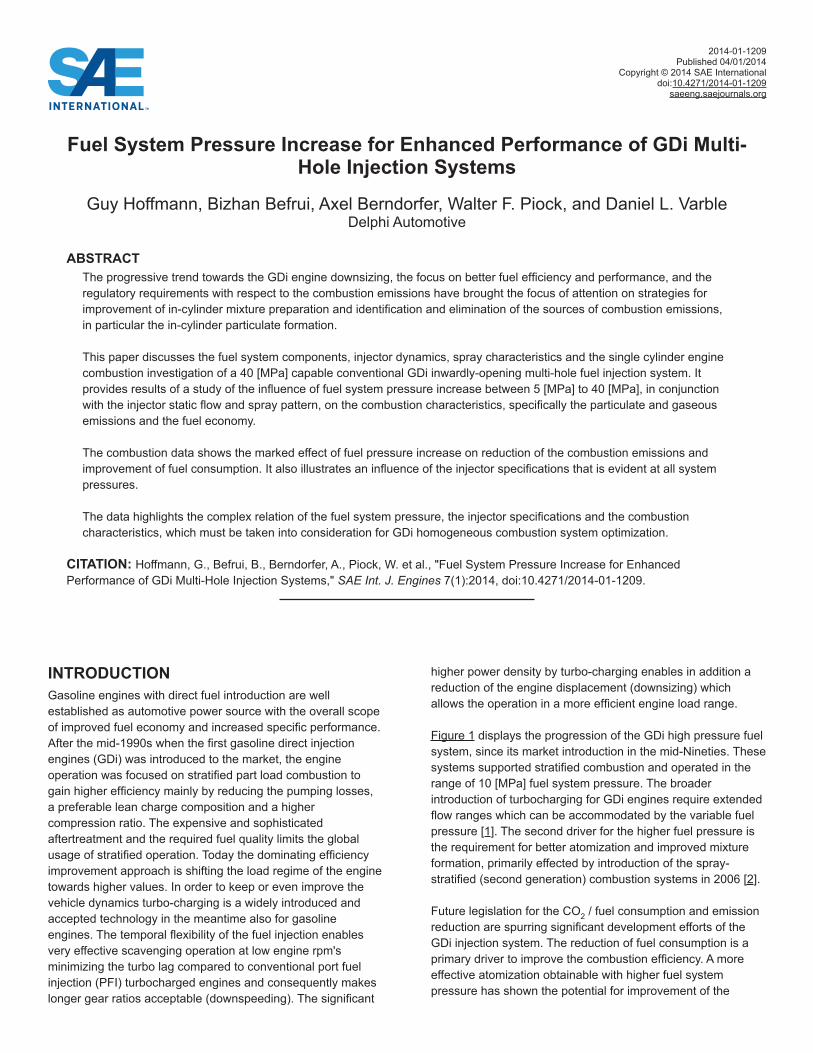
Figure 1 displays the progression of the GDi high pressure fuel system, since its market introduction in the mid-Nineties. These systems supported stratified combustion and operated in the range of 10 [MPa] fuel system pressure. The broader introduction of turbocharging for GDi engines require extended flow ranges which can be accommodated by the variable fuel pressure [1]. The second driver for the higher fuel pressure is the requirement for better atomization and improved mixture formation, primarily effected by introduction of the spray-stratified (second generation) combustion systems in 2006 [2].
Future legislation for the CO2 / fuel consumption and emission reduction are spurring significant development efforts of the GDi injection system. The reduction of fuel consumption is a primary driver to improve the combustion efficiency. A more effective atomization obtainable with higher fuel system pressure has shown the potential for improvement of the
Fuel System Pressure Increase for Enhanced Performance of GDi Multi-Hole Injection Systems
Guy Hoffmann, Bizhan Befrui, Axel Berndorfer, Walter F. Piock, and Daniel L. VarbleDelphi Automotive
ABSTRACTThe progressive trend towards the GDi engine downsizing, the focus on better fuel efficiency and performance, and the regulatory requirements with respect to the combustion emissions have brought the focus of attention on strategies for improvement of in-cylinder mixture preparation and identification and elimination of the sources of combustion emissions, in particular the in-cylinder particulate formation.
This paper discusses the fuel system components, injector dynamics, spray characteristics and the single cylinder engine combustion investigation of a 40 [MPa] capable conventional GDi inwardly-opening multi-hole fuel injection system. It provides results of a study of the influence of fuel system pressure increase between 5 [MPa] to 40 [MPa], in conjunction with the injector static flow and spray pattern, on the combustion characteristics, specifically the particulate and gaseous emissions and the fuel economy.
The combustion data shows the marked effect of fuel pressure increase on reduction of the combustion emissions and improvement of fuel consumption. It also illustrates an influence of the injector specifications that is evident at all system pressures.
The data highlights the complex relation of the fuel system pressure, the injector specifications and the combustion characteristics, which must be taken into consideration for GDi homogeneous combustion system optimization.
CITATION: Hoffmann, G., Befrui, B., Berndorfer, A., Piock, W. et al., "Fuel System Pressure Increase for Enhanced Performance of GDi Multi-Hole Injection Systems," SAE Int. J. Engines 7(1):2014, doi:10.4271/2014-01-1209.
2014-01-1209Published 04/01/2014
Copyright © 2014 SAE Internationaldoi:10.4271/2014-01-1209
saeeng.saejournals.org
combustion performance for GDi homogeneous systems [3, 4]. The future emission legislation of Euro 6C [5, 6], becoming effective in Europe in 2017, is another major driver for a GDi fuel system pressure increase. Especially in the case particulate emissions - mass as well as number - a higher fuel pressure is capable to sustainably reduce the engine emissions [7, 8].
Figure 1. Pressure Evolution for GDi Systems and Future Trend
In the following chapters, the requirements and implications of a system pressure increase to 40 [MPa] for the GDi conventional multi-hole fuel system components are discussed. Then, the influence of fuel injection increase between 5 [MPa] and 40 [MPa] on the injector hydraulic performance and the spray structure, penetration and atomization are illustrated with the aid of experimental data. The effect of fuel system pressure on the combustion characteristics is of primary interest: in this context the single-cylinder engine combustion data for three GDi multi-hole injectors -with different spray patterns and static flows - operating at different fuel pressures are presented and discussed. Finally, a summary of the main findings of this study is provided.
FUEL SYSTEM ASPECTSOne reason for introduction of GDi systems is to improve the fuel economy of gasoline powered vehicles. Therefore it is necessary to carefully assess all required measures, with respect to the fuel system, and implications for total engine outputs in order to meet this overall objective. A fuel system pressure increase can be expected to elevate the parasitic losses and, on this ground alone, will be counterproductive for engine CO2 reduction. A comprehensive review and optimization of the entire fuel system - from the fuel tank to the injector - needs to performed. This must include all pertinent aspect of a fuel system pressure increase, for instance the structural, hydraulic as well as the system component interactions, in order to guarantee a safe and efficient operation in engine applications.
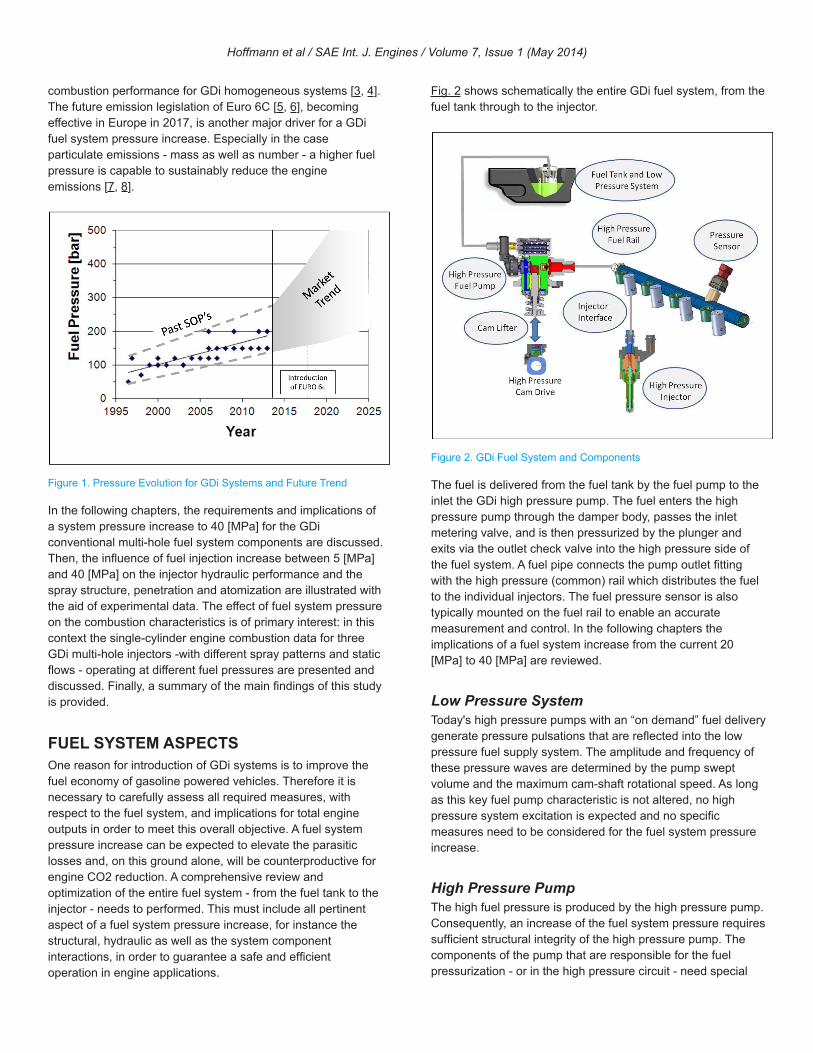
Fig. 2 shows schematically the entire GDi fuel system, from the fuel tank through to the injector.
Figure 2. GDi Fuel System and Components
The fuel is delivered from the fuel tank by the fuel pump to the inlet the GDi high pressure pump. The fuel enters the high pressure pump through the damper body, passes the inlet metering valve, and is then pressurized by the plunger and exits via the outlet check valve into the high pressure side of the fuel system. A fuel pipe connects the pump outlet fitting with the high pressure (common) rail which distributes the fuel to the individual injectors. The fuel pressure sensor is also typically mounted on the fuel rail to enable an accurate measurement and control. In the following chapters the implications of a fuel system increase from the current 20 [MPa] to 40 [MPa] are reviewed.
Low Pressure SystemToday's high pressure pumps with an “on demand” fuel delivery generate pressure pulsations that are reflected into the low pressure fuel supply system. The amplitude and frequency of these pressure waves are determined by the pump swept volume and the maximum cam-shaft rotational speed. As long as this key fuel pump characteristic is not altered, no high pressure system excitation is expected and no specific measures need to be considered for the fuel system pressure increase.
High Pressure PumpThe high fuel pressure is produced by the high pressure pump. Consequently, an increase of the fuel system pressure requires sufficient structural integrity of the high pressure pump. The components of the pump that are responsible for the fuel pressurization - or in the high pressure circuit - need special
Hoffmann et al / SAE Int. J. Engines / Volume 7, Issue 1 (May 2014)
attention. In particular, interfaces on the high pressure side that are normally welded must be rigorously design optimized in order to withstand a significant higher fatigue stress levels.
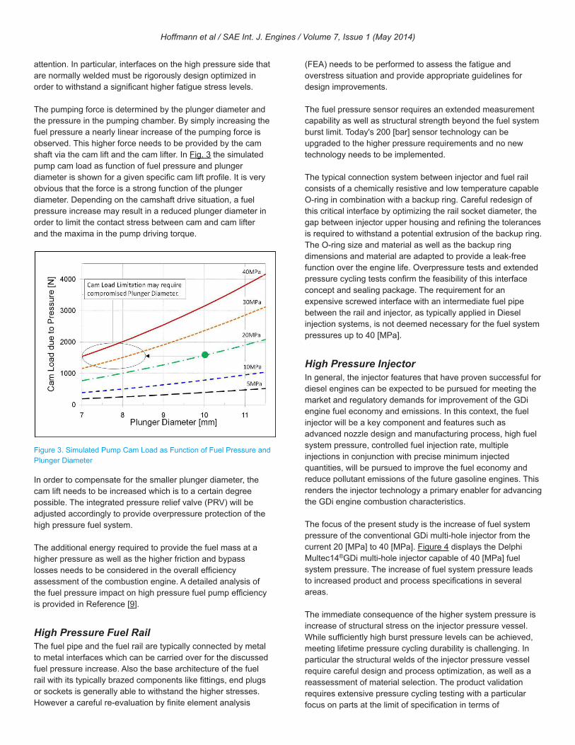
The pumping force is determined by the plunger diameter and the pressure in the pumping chamber. By simply increasing the fuel pressure a nearly linear increase of the pumping force is observed. This higher force needs to be provided by the cam shaft via the cam lift and the cam lifter. In Fig. 3 the simulated pump cam load as function of fuel pressure and plunger diameter is shown for a given specific cam lift profile. It is very obvious that the force is a strong function of the plunger diameter. Depending on the camshaft drive situation, a fuel pressure increase may result in a reduced plunger diameter in order to limit the contact stress between cam and cam lifter and the maxima in the pump driving torque.
Figure 3. Simulated Pump Cam Load as Function of Fuel Pressure and Plunger Diameter
In order to compensate for the smaller plunger diameter, the cam lift needs to be increased which is to a certain degree possible. The integrated pressure relief valve (PRV) will be adjusted accordingly to provide overpressure protection of the high pressure fuel system.
The additional energy required to provide the fuel mass at a higher pressure as well as the higher friction and bypass losses needs to be considered in the overall efficiency assessment of the combustion engine. A detailed analysis of the fuel pressure impact on high pressure fuel pump efficiency is provided in Reference [9].
High Pressure Fuel RailThe fuel pipe and the fuel rail are typically connected by metal to metal interfaces which can be carried over for the discussed fuel pressure increase. Also the base architecture of the fuel rail with its typically brazed components like fittings, end plugs or sockets is generally able to withstand the higher stresses. However a careful re-evaluation by finite element analysis
(FEA) needs to be performed to assess the fatigue and overstress situation and provide appropriate guidelines for design improvements.
The fuel pressure sensor requires an extended measurement capability as well as structural strength beyond the fuel system burst limit. Today's 200 [bar] sensor technology can be upgraded to the higher pressure requirements and no new technology needs to be implemented.
The typical connection system between injector and fuel rail consists of a chemically resistive and low temperature capable O-ring in combination with a backup ring. Careful redesign of this critical interface by optimizing the rail socket diameter, the gap between injector upper housing and refining the tolerances is required to withstand a potential extrusion of the backup ring. The O-ring size and material as well as the backup ring dimensions and material are adapted to provide a leak-free function over the engine life. Overpressure tests and extended pressure cycling tests confirm the feasibility of this interface concept and sealing package. The requirement for an expensive screwed interface with an intermediate fuel pipe between the rail and injector, as typically applied in Diesel injection systems, is not deemed necessary for the fuel system pressures up to 40 [MPa].
High Pressure InjectorIn general, the injector features that have proven successful for diesel engines can be expected to be pursued for meeting the market and regulatory demands for improvement of the GDi engine fuel economy and emissions. In this context, the fuel injector will be a key component and features such as advanced nozzle design and manufacturing process, high fuel system pressure, controlled fuel injection rate, multiple injections in conjunction with precise minimum injected quantities, will be pursued to improve the fuel economy and reduce pollutant emissions of the future gasoline engines. This renders the injector technology a primary enabler for advancing the GDi engine combustion characteristics.
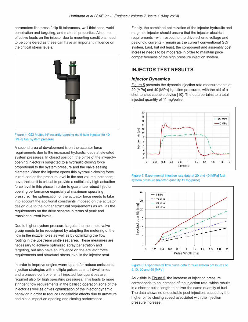
The focus of the present study is the increase of fuel system pressure of the conventional GDi multi-hole injector from the current 20 [MPa] to 40 [MPa]. Figure 4 displays the Delphi Multec14®GDi multi-hole injector capable of 40 [MPa] fuel system pressure. The increase of fuel system pressure leads to increased product and process specifications in several areas.
The immediate consequence of the higher system pressure is increase of structural stress on the injector pressure vessel. While sufficiently high burst pressure levels can be achieved, meeting lifetime pressure cycling durability is challenging. In particular the structural welds of the injector pressure vessel require careful design and process optimization, as well as a reassessment of material selection. The product validation requires extensive pressure cycling testing with a particular focus on parts at the limit of specification in terms of
Hoffmann et al / SAE Int. J. Engines / Volume 7, Issue 1 (May 2014)
parameters like press / slip fit tolerances, wall thickness, weld penetration and targeting, and material properties. Also, the effective loads on the injector due to mounting conditions need to be considered as these can have an important influence on the critical stress levels.
Figure 4. GDi Multec14®inwardly-opening multi-hole injector for 40 [MPa] fuel system pressure
A second area of development is on the actuator force requirements due to the increased hydraulic loads at elevated system pressures. In closed position, the pintle of the inwardly-opening injector is subjected to a hydraulic closing force proportional to the system pressure and the valve sealing diameter. When the injector opens this hydraulic closing force is reduced as the pressure level in the sac volume increases; nevertheless it is critical to provide a sufficiently high actuation force level in this phase in order to guarantee robust injector opening performance especially at maximum operating pressure. The optimization of the actuator force needs to take into account the additional constraints imposed on the actuator design due to the higher structural requirements as well as the requirements on the drive scheme in terms of peak and transient current levels.
Due to higher system pressure targets, the multi-hole valve group needs to be redesigned by adapting the metering of the flow in the nozzle holes as well as by optimizing the flow routing in the upstream pintle seat area. These measures are necessary to achieve optimized spray penetration and targeting, but also have an influence on the actuator force requirements and structural stress level in the injector seat.
In order to improve engine warm-up and/or reduce emissions, injection strategies with multiple pulses at small dwell times and a precise control of small injected fuel quantities are required also for high operating pressures. This leads to more stringent flow requirements in the ballistic operation zone of the injector as well as drives optimization of the injector dynamic behavior in order to reduce undesirable effects due to armature and pintle impact on opening and closing performance.
Finally, the combined optimization of the injector hydraulic and magnetic injector should ensure that the injector electrical requirements - with respect to the drive scheme voltage and peak/hold currents - remain as the current conventional GDi system. Last, but not least, the component and assembly cost increase needs to be moderate in order to maintain price competitiveness of the high pressure injection system.
INJECTOR TEST RESULTS
Injector DynamicsFigure 5 presents the dynamic injection rate measurements at 20 [MPa] and 40 [MPa] injection pressures, with the aid of a shot-to-shot capable device [10]. The data pertains to a total injected quantity of 11 mg/pulse.
Figure 5. Experimental injection rate data at 20 and 40 [MPa] fuel system pressure (injected quantity 11 mg/pulse)
Figure 6. Experimental flow curve data for fuel system pressures of 5,10, 20 and 40 [MPa]
As visible in Figure 5, the increase of injection pressure corresponds to an increase of the injection rate, which results in a shorter pulse length to deliver the same quantity of fuel. The data shows no undesirable post-injection, caused by the higher pintle closing speed associated with the injection pressure increase.
Hoffmann et al / SAE Int. J. Engines / Volume 7, Issue 1 (May 2014)
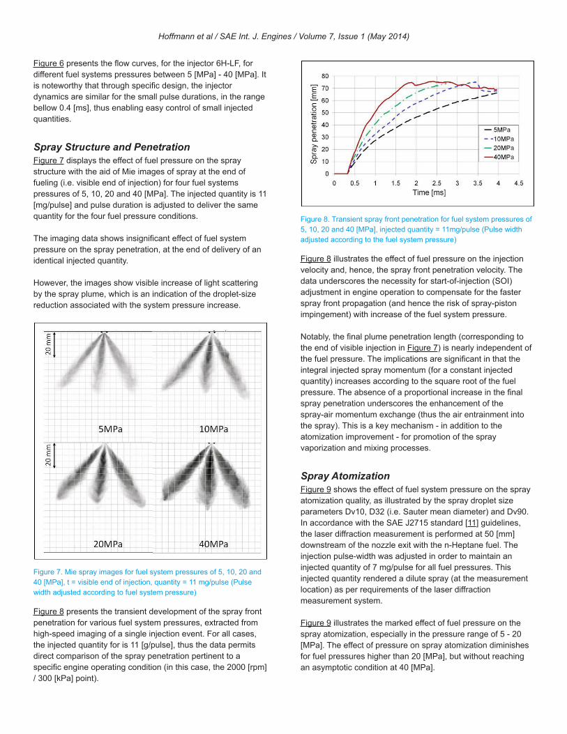
Figure 6 presents the flow curves, for the injector 6H-LF, for different fuel systems pressures between 5 [MPa] - 40 [MPa]. It is noteworthy that through specific design, the injector dynamics are similar for the small pulse durations, in the range bellow 0.4 [ms], thus enabling easy control of small injected quantities.
Spray Structure and PenetrationFigure 7 displays the effect of fuel pressure on the spray structure with the aid of Mie images of spray at the end of fueling (i.e. visible end of injection) for four fuel systems pressures of 5, 10, 20 and 40 [MPa]. The injected quantity is 11 [mg/pulse] and pulse duration is adjusted to deliver the same quantity for the four fuel pressure conditions.
The imaging data shows insignificant effect of fuel system pressure on the spray penetration, at the end of delivery of an identical injected quantity.
However, the images show visible increase of light scattering by the spray plume, which is an indication of the droplet-size reduction associated with the system pressure increase.
Figure 7. Mie spray images for fuel system pressures of 5, 10, 20 and 40 [MPa], t = visible end of injection, quantity = 11 mg/pulse (Pulse width adjusted according to fuel system pressure)
Figure 8 presents the transient development of the spray front penetration for various fuel system pressures, extracted from high-speed imaging of a single injection event. For all cases, the injected quantity for is 11 [g/pulse], thus the data permits direct comparison of the spray penetration pertinent to a specific engine operating condition (in this case, the 2000 [rpm] / 300 [kPa] point).
Figure 8. Transient spray front penetration for fuel system pressures of 5, 10, 20 and 40 [MPa], injected quantity = 11mg/pulse (Pulse width adjusted according to the fuel system pressure)
Figure 8 illustrates the effect of fuel pressure on the injection velocity and, hence, the spray front penetration velocity. The data underscores the necessity for start-of-injection (SOI) adjustment in engine operation to compensate for the faster spray front propagation (and hence the risk of spray-piston impingement) with increase of the fuel system pressure.
Notably, the final plume penetration length (corresponding to the end of visible injection in Figure 7) is nearly independent of the fuel pressure. The implications are significant in that the integral injected spray momentum (for a constant injected quantity) increases according to the square root of the fuel pressure. The absence of a proportional increase in the final spray penetration underscores the enhancement of the spray-air momentum exchange (thus the air entrainment into the spray). This is a key mechanism - in addition to the atomization improvement - for promotion of the spray vaporization and mixing processes.
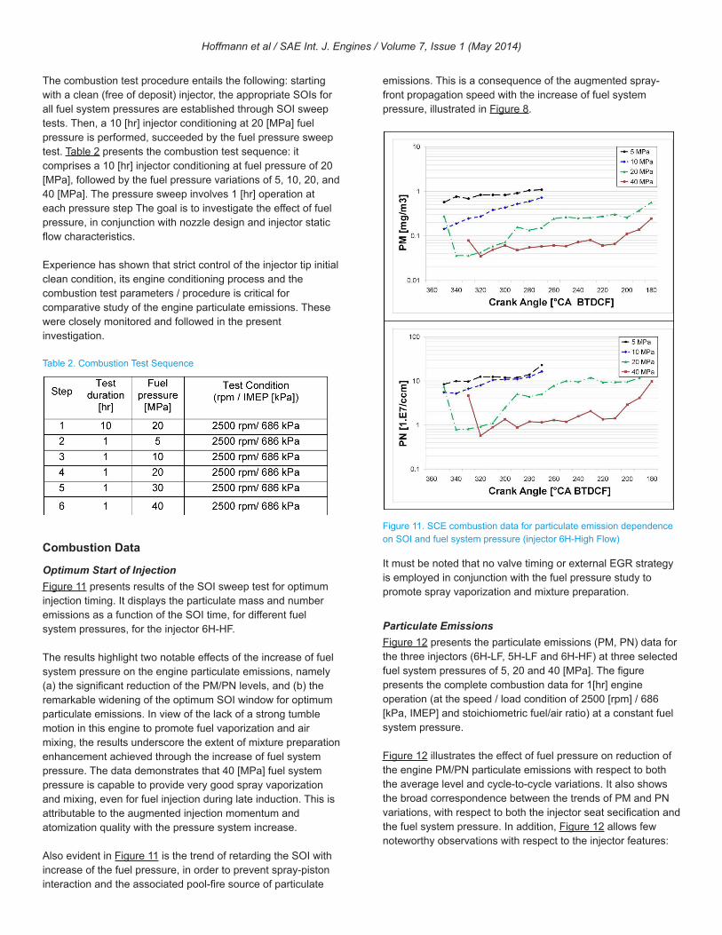
Spray AtomizationFigure 9 shows the effect of fuel system pressure on the spray atomization quality, as illustrated by the spray droplet size parameters Dv10, D32 (i.e. Sauter mean diameter) and Dv90. In accordance with the SAE J2715 standard [11] guidelines, the laser diffraction measurement is performed at 50 [mm] downstream of the nozzle exit with the n-Heptane fuel. The injection pulse-width was adjusted in order to maintain an injected quantity of 7 mg/pulse for all fuel pressures. This injected quantity rendered a dilute spray (at the measurement location) as per requirements of the laser diffraction measurement system.
Figure 9 illustrates the marked effect of fuel pressure on the spray atomization, especially in the pressure range of 5 - 20 [MPa]. The effect of pressure on spray atomization diminishes for fuel pressures higher than 20 [MPa], but without reaching an asymptotic condition at 40 [MPa].
Hoffmann et al / SAE Int. J. Engines / Volume 7, Issue 1 (May 2014)
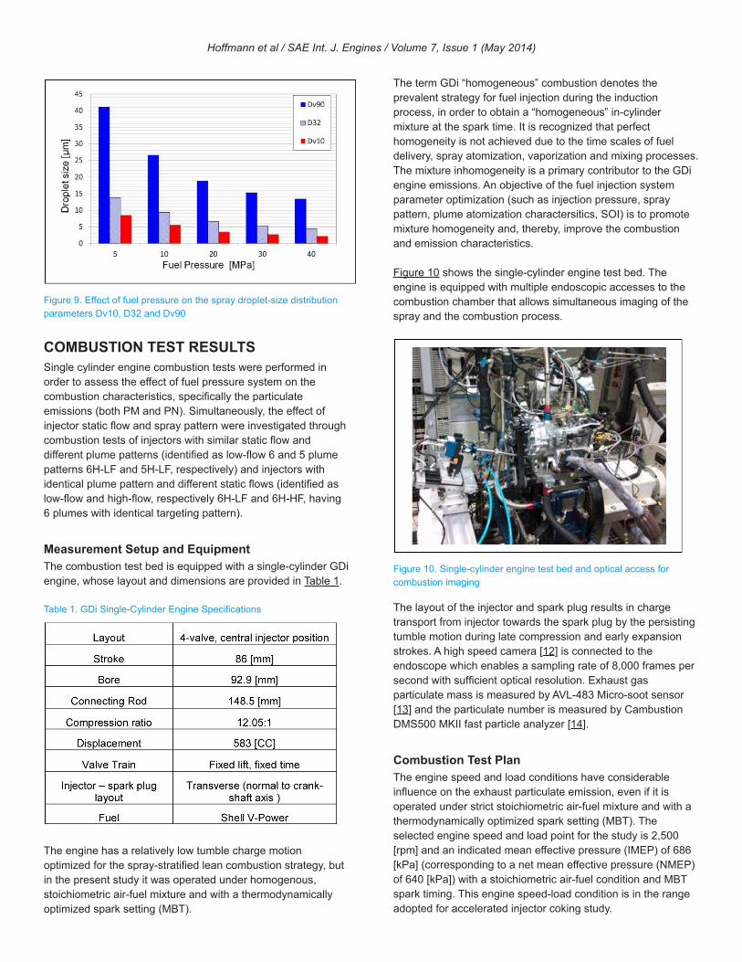
Figure 9. Effect of fuel pressure on the spray droplet-size distribution parameters Dv10, D32 and Dv90
COMBUSTION TEST RESULTSSingle cylinder engine combustion tests were performed in order to assess the effect of fuel pressure system on the combustion characteristics, specifically the particulate emissions (both PM and PN). Simultaneously, the effect of injector static flow and spray pattern were investigated through combustion tests of injectors with similar static flow and different plume patterns (identified as low-flow 6 and 5 plume patterns 6H-LF and 5H-LF, respectively) and injectors with identical plume pattern and different static flows (identified as low-flow and high-flow, respectively 6H-LF and 6H-HF, having 6 plumes with identical targeting pattern).
Measurement Setup and EquipmentThe combustion test bed is equipped with a single-cylinder GDi engine, whose layout and dimensions are provided in Table 1.
Table 1. GDi Single-Cylinder Engine Specifications
The engine has a relatively low tumble charge motion optimized for the spray-stratified lean combustion strategy, but in the present study it was operated under homogenous, stoichiometric air-fuel mixture and with a thermodynamically optimized spark setting (MBT).
The term GDi “homogeneous” combustion denotes the prevalent strategy for fuel injection during the induction process, in order to obtain a “homogeneous” in-cylinder mixture at the spark time. It is recognized that perfect homogeneity is not achieved due to the time scales of fuel delivery, spray atomization, vaporization and mixing processes. The mixture inhomogeneity is a primary contributor to the GDi engine emissions. An objective of the fuel injection system parameter optimization (such as injection pressure, spray pattern, plume atomization charactersitics, SOI) is to promote mixture homogeneity and, thereby, improve the combustion and emission characteristics.
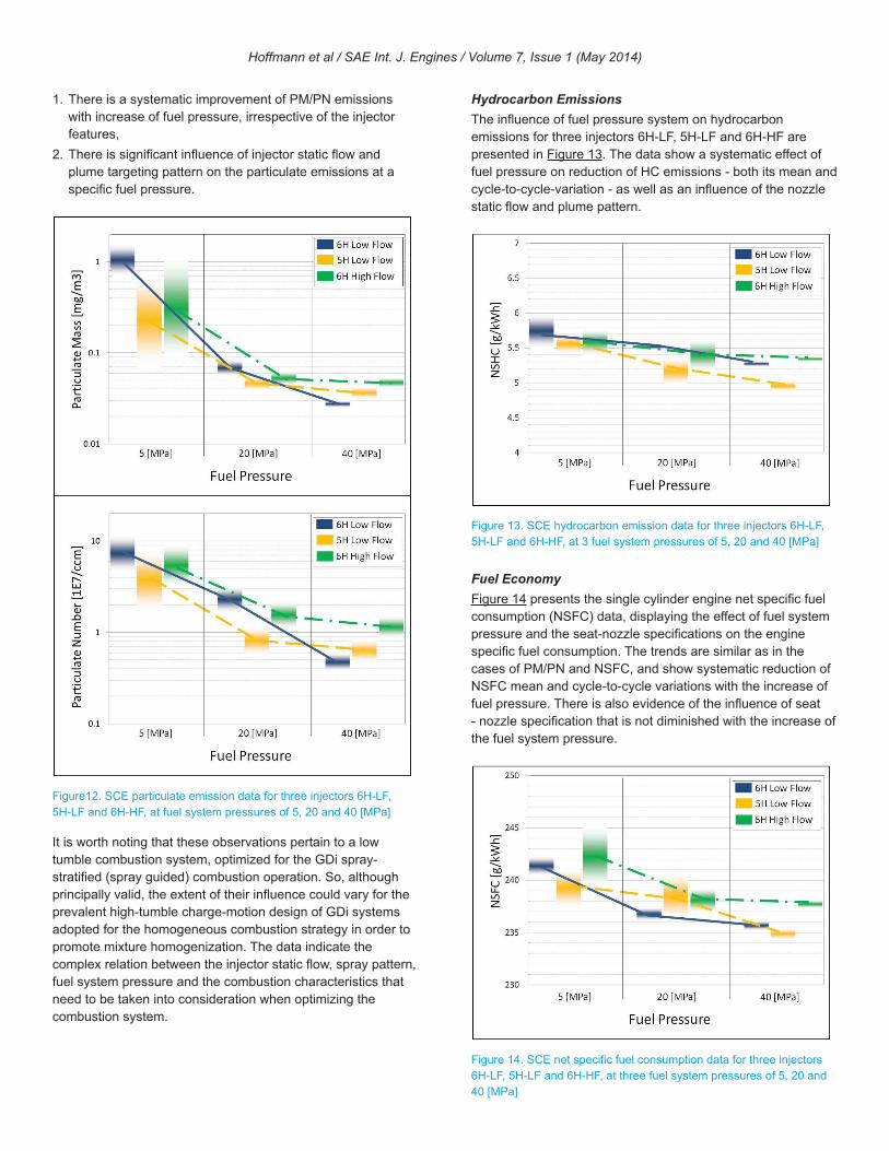
Figure 10 shows the single-cylinder engine test bed. The engine is equipped with multiple endoscopic accesses to the combustion chamber that allows simultaneous imaging of the spray and the combustion process.
Figure 10. Single-cylinder engine test bed and optical access for combustion imaging
The layout of the injector and spark plug results in charge transport from injector towards the spark plug by the persisting tumble motion during late compression and early expansion strokes. A high speed camera [12] is connected to the endoscope which enables a sampling rate of 8,000 frames per second with sufficient optical resolution. Exhaust gas particulate mass is measured by AVL-483 Micro-soot sensor [13] and the particulate number is measured by Cambustion DMS500 MKII fast particle analyzer [14].
Combustion Test PlanThe engine speed and load conditions have considerable influence on the exhaust particulate emission, even if it is operated under strict stoichiometric air-fuel mixture and with a thermodynamically optimized spark setting (MBT). The selected engine speed and load point for the study is 2,500 [rpm] and an indicated mean effective pressure (IMEP) of 686 [kPa] (corresponding to a net mean effective pressure (NMEP) of 640 [kPa]) with a stoichiometric air-fuel condition and MBT spark timing. This engine speed-load condition is in the range adopted for accelerated injector coking study.
Hoffmann et al / SAE Int. J. Engines / Volume 7, Issue 1 (May 2014)
The combustion test procedure entails the following: starting with a clean (free of deposit) injector, the appropriate SOIs for all fuel system pressures are established through SOI sweep tests. Then, a 10 [hr] injector conditioning at 20 [MPa] fuel pressure is performed, succeeded by the fuel pressure sweep test. Table 2 presents the combustion test sequence: it comprises a 10 [hr] injector conditioning at fuel pressure of 20 [MPa], followed by the fuel pressure variations of 5, 10, 20, and 40 [MPa]. The pressure sweep involves 1 [hr] operation at each pressure step The goal is to investigate the effect of fuel pressure, in conjunction with nozzle design and injector static flow characteristics.
Experience has shown that strict control of the injector tip initial clean condition, its engine conditioning process and the combustion test parameters / procedure is critical for comparative study of the engine particulate emissions. These were closely monitored and followed in the present investigation.
Table 2. Combustion Test Sequence
Combustion Data
Optimum Start of InjectionFigure 11 presents results of the SOI sweep test for optimum injection timing. It displays the particulate mass and number emissions as a function of the SOI time, for different fuel system pressures, for the injector 6H-HF.
The results highlight two notable effects of the increase of fuel system pressure on the engine particulate emissions, namely (a) the significant reduction of the PM/PN levels, and (b) the remarkable widening of the optimum SOI window for optimum particulate emissions. In view of the lack of a strong tumble motion in this engine to promote fuel vaporization and air mixing, the results underscore the extent of mixture preparation enhancement achieved through the increase of fuel system pressure. The data demonstrates that 40 [MPa] fuel system pressure is capable to provide very good spray vaporization and mixing, even for fuel injection during late induction. This is attributable to the augmented injection momentum and atomization quality with the pressure system increase.
Also evident in Figure 11 is the trend of retarding the SOI with increase of the fuel pressure, in order to prevent spray-piston interaction and the associated pool-fire source of particulate
emissions. This is a consequence of the augmented spray-front propagation speed with the increase of fuel system pressure, illustrated in Figure 8.
Figure 11. SCE combustion data for particulate emission dependence on SOI and fuel system pressure (injector 6H-High Flow)
It must be noted that no valve timing or external EGR strategy is employed in conjunction with the fuel pressure study to promote spray vaporization and mixture preparation.
Particulate EmissionsFigure 12 presents the particulate emissions (PM, PN) data for the three injectors (6H-LF, 5H-LF and 6H-HF) at three selected fuel system pressures of 5, 20 and 40 [MPa]. The figure presents the complete combustion data for 1[hr] engine operation (at the speed / load condition of 2500 [rpm] / 686 [kPa, IMEP] and stoichiometric fuel/air ratio) at a constant fuel system pressure.
Figure 12 illustrates the effect of fuel pressure on reduction of the engine PM/PN particulate emissions with respect to both the average level and cycle-to-cycle variations. It also shows the broad correspondence between the trends of PM and PN variations, with respect to both the injector seat secification and the fuel system pressure. In addition, Figure 12 allows few noteworthy observations with respect to the injector features:
Hoffmann et al / SAE Int. J. Engines / Volume 7, Issue 1 (May 2014)
1. There is a systematic improvement of PM/PN emissions with increase of fuel pressure, irrespective of the injector features,
2. There is significant influence of injector static flow and plume targeting pattern on the particulate emissions at a specific fuel pressure.
Figure12. SCE particulate emission data for three injectors 6H-LF, 5H-LF and 6H-HF, at fuel system pressures of 5, 20 and 40 [MPa]
It is worth noting that these observations pertain to a low tumble combustion system, optimized for the GDi spray-stratified (spray guided) combustion operation. So, although principally valid, the extent of their influence could vary for the prevalent high-tumble charge-motion design of GDi systems adopted for the homogeneous combustion strategy in order to promote mixture homogenization. The data indicate the complex relation between the injector static flow, spray pattern, fuel system pressure and the combustion characteristics that need to be taken into consideration when optimizing the combustion system.
Hydrocarbon EmissionsThe influence of fuel pressure system on hydrocarbon emissions for three injectors 6H-LF, 5H-LF and 6H-HF are presented in Figure 13. The data show a systematic effect of fuel pressure on reduction of HC emissions - both its mean and cycle-to-cycle-variation - as well as an influence of the nozzle static flow and plume pattern.
Figure 13. SCE hydrocarbon emission data for three injectors 6H-LF, 5H-LF and 6H-HF, at 3 fuel system pressures of 5, 20 and 40 [MPa]
Fuel EconomyFigure 14 presents the single cylinder engine net specific fuel consumption (NSFC) data, displaying the effect of fuel system pressure and the seat-nozzle specifications on the engine specific fuel consumption. The trends are similar as in the cases of PM/PN and NSFC, and show systematic reduction of NSFC mean and cycle-to-cycle variations with the increase of fuel pressure. There is also evidence of the influence of seat - nozzle specification that is not diminished with the increase of the fuel system pressure.
Figure 14. SCE net specific fuel consumption data for three injectors 6H-LF, 5H-LF and 6H-HF, at three fuel system pressures of 5, 20 and 40 [MPa]
Hoffmann et al / SAE Int. J. Engines / Volume 7, Issue 1 (May 2014)

SUMMARY AND OUTLOOKThe single cylinder engine combustion data shows a pronounced influence of fuel pressure on reduction of the PM and PN emissions, both the mean and the cycle-to-cycle variations, concurrent with parallel improvements of the gaseous emissions and fuel consumption. The data also offers evidence of significant influences of the injector static flow and the spray pattern on the combustion and emission characteristics.
The data underscore the complex relation of the injector specifications, fuel system pressure and the combustion characteristics. It is noteworthy that although the magnitude of the fuel pressure influence on the combustion characteristics varies for individual injectors, overall, the effect of injector specifications is not diminished by the increase of the fuel system pressure.
The single cylinder combustion tests were carried out with due care to ensure the injectors were subjected to identical conditioning and tests procedure. This is an absolute requirement to ensure the PN/PM emissions data are not influenced by uncontrolled parameters.
It is recognized that due the low-tumble charge motion design of the single-cylinder engine, the fuel injection system plays a major role in the mixture preparation in the present study. On this, the single-cylinder engine may differ from the prevalent high-tumble GDi homogeneous engines. This underscores the necessity for combustion system optimization, taking into account the injector specification, spray pattern, fuel system pressure and the engine design and performance parameters.
Further investigations of the influence of fuel system pressure on the GDi homogenous combustion fuel economy and emissions are in progress and will be reported.
REFERENCES1. Piock, W., Pinter, A., and Fraidl, G., “Gasoline Direct Injection and
Engine Boosting,” SAE International TOPTEC, Aug. 2002.2. Waltner A., Lueckert P., Schaupp U., Rau E., Kemmler R. Weller
R., “Future Technology of the Spark-ignition Engine: Spray-guided Direct Injection with Piezo Injector,” 27th Vienna Motor Symposium 2006
3. Nauwerck, A., Pfeil, J., Velji, A., Spicher, U. et al., “A Basic Experimental Study of Gasoline Direct Injection at Significantly High Injection Pressures,” SAE Technical Paper 2005-01-0098, 2005, doi:10.4271/2005-01-0098.
4. Herweg R., Haase D., Dieler T., Berndt F., Rottenkolber G.: “Lean Burn Combustion for Gasoline Engines: Potential of High Frequency Ignition and High Pressure Injection,” 13th Stuttgart International Conference Automotive and Engine Technology, 2013
5. Regulation (EF) No 715 /2007 of the European Parliament and the Council of 20 June 2007, http://eurlex.europa.eu/LexUriServ/LexUriServ.do?uri=OJ:L:2007:171:0001:0001:EN:PDF
6. Commission Regulation (EU) No 459/2012 of 29 May 2012, http://eur-lex.europa.eu/LexUriServ/LexUriServ.do?uri=CELEX:32012R0459:en:NOT
7. Berndorfer, A., Breuer, S., Piock, W., and Von Bacho, P., “Diffusion Combustion Phenomena in GDi Engines caused by Injection Process,” SAE Technical Paper 2013-01-0261, 2013, doi:10.4271/2013-01-0261.
8. Klauer N., Klüting M., Schünemann E., Schwarz C., Steinparzer F.:“BMW TwinPower Turbo Gasoline Engine Technology - Enabling Compliance with worldwide Exhaust Gas Emissions Requirements,” 34th Vienna Motor Symposium, 2013
9. Husted, H., Spegar, T., and Spakowski, J., “The Effects of GDi Fuel Pressure on Fuel Economy,” SAE Technical Paper 2014-01-1438, 2014, doi:10.4271/2014-01-1438.
10. Mexus diesel and gasoline light duty shot-to-shot injection measuring system, Loccioni Group, http://mobility.loccioni.com/pdf/MexusDLD-GLD.pdf
11. Hung, D., Harrington, D., Gandhi, A., Markle, L. et al., “Gasoline Fuel Injector Spray Measurement and Characterization - A New SAE J2715 Recommended Practice,” SAE Int. J. Fuels Lubr. 1(1):534-548, 2008, doi:10.4271/2008-01-1068.
12. Technical documentation: MotionBLITZ EoSens ® mini1, Mikrotron GmbH, Germany, 2011.
13. Technical Documentation: Micro Soot Sensor, AVLGmbH, Austria, 2008.
14. Technical Documentation: DMS500 MkII Transient Engine Particulate Analyzer, Cambustion LTD, UK, 2011.
ACKNOWLEDGMENTSThe authors would like to acknowledge the significant efforts of colleagues at the Delphi Technical Center Rochester and the Delphi Customer Technology Centre Luxembourg, specifically N. Mastro, D. Dalo, P. Spiekermann, C. Deliege and C. Majerus, who made this project possible.
ABBREVIATIONSATDC - After top dead center
CAD - Crank Angle Degrees
MBT - Maximum brake torque
NMEP - Net mean effective pressure
NSFC - Net specific fuel consumption
PM - Particulate Mass emission
PN - Particulate Number emission
SOI - Start of Injection (start of injector energizing)
Euro-6C - Commission Regulation (EU) No 459/2012 of 29 May 2012
All rights reserved. No part of this publication may be reproduced, stored in a retrieval system, or transmitted, in any form or by any means, electronic, mechanical, photocopying, recording, or otherwise, without the prior written permission of SAE International.
Positions and opinions advanced in this paper are those of the author(s) and not necessarily those of SAE International. The author is solely responsible for the content of the paper.
Hoffmann et al / SAE Int. J. Engines / Volume 7, Issue 1 (May 2014)