Fuel Cell Systems Overview - ocw.snu.ac.kr
30
Fuel Cell Systems Overview
Transcript of Fuel Cell Systems Overview - ocw.snu.ac.kr

Fuel Cell Systems Overview

Fuel Cell Systems

Fuel Cell Stacks

Fuel Cell Stacks

Fuel Cell Stacks

Tubular SOFC

Tubular SOFC

Tubular SOFC

Flat Tubular SOFC
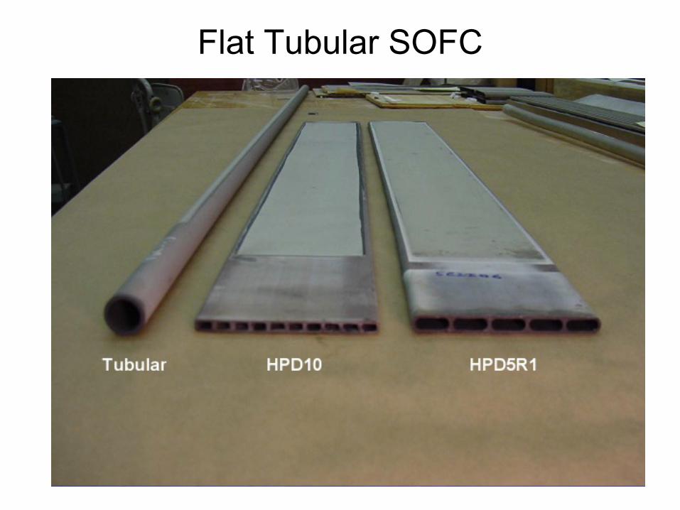
Flat Tubular SOFC

Flat Tubular SOFC
8
1.0 REPORT DETAILS
Introduction The components of the LGFSC Solid Oxide Fuel Cell (SOFC) power plant are shown in Figure 1. Flat porous ceramic tubes (1) are the substrate for fuel cells printed with industrial screen-printing equipment (2). The fuel cell tubes (3) are assembled into strips (4) with manifolds to direct the flow of fuel inside the tubes. The strips are incorporated into Integrated Block (IB) (5), which direct the flow of air and fuel, control the thermal environment and extract electrical power. The IB’s are combined into a fuel cell vessel (6) with a turbo generator (8) to supply air and pressure to form the Generator Module (GM) (7). The GM is packaged with Balance of Plant (BOP) equipment to form the system.
Figure 1 LGFSC Solid Oxide Fuel Cell (SOFC) Power Plant
Task 1.0 - Project Management LG Fuel Cell Systems Inc. (LGFCS) will manage and direct the project in accordance with a Project Management Plan to meet all technical, schedule and budget objectives and requirements. LGFCS will coordinate activities to accomplish the work. LGFCS will ensure that

Planar SOFC’s
Ceres Power – Metal supported SOFC
R.T. Leah, A. Bone, E. Hammer, A. Selcuk, M. Rahman, A. Clare, S. Mukerjee, M. Selby ECS Transactions. 78 (2017) 87.
17

Thermal Management

Thermal Management
Honda’s cooling channel design

Fuel Delievary/Processing
•Energy density of fuel
•Hydrogen storage

Hydrogen Storage
•Compressed hydrogen•Easy to store and retrieve
•Safety issue
•Additional energy to compress (10% loss for 300bar)
•Liquid hydrogen•High energy density
•Additional energy to liquify (30% loss)
•Boil off due to phase change

Hydrogen Storage•Metal hydride
•Excellent volumetric density
•Poor gravimetric density
•Expensive materials (e.g. Pd)
•Hydrogen embrittlement
•May Need cooling or heating during charging/discharging

Hydrogen Storage Technology

Hydrogen Storage Technology

Hydrogen Carrier
•Hydrocarbon
-Methane(CH4), ethane(C2H6), propane(C3H8)…
-Methanol(CH3OH), formic acid(HCOOH)
-Gasoline(CnH1.87n), diesel…
•Chemical hydride
-Sodium borohydride(NaBH4), Ammonia(NH3)..

Hydrogen Carrier
•Direct electro-oxidation
-DMFC, DFAFC, DBFC…
-Complicated & slow kinetics: low efficiency
ex)DMFC: Anode: CH3OH + H2O => CO2 + 6H+ + 6e-
Cathode: 1.5O2 + 6H+ + 6e => 3H2O
DBFC: Anode: NaBH4 + 8OH- => NaBO2 + 6H2O + 8e-Cathode: 2O2 + 4H2O + 8e- => 8OH-

Hydrogen Carrier•External reforming
-High energy density of fuel
-CO issue, hydrogen separation
Ex) steam reforming
CH3OH + H2O => CO2 + 3H2
C (coal) + 2H2O => CO2 + 2H2

Delivered Hydrogen Cost
*The National Academies, 2004

Hydrogen Carrier•Internal Reforming
-Simple system
-Appropriate for high temperature fuel cells
-Careful on catalyst design

DOE Target

Power Regulation•Loading of fuel cells tend to change
•DC/DC conversion: 85~98% efficiency
•Step-up or step-down

Power Inversion•DC/AC conversion
•Appropriate stationary, automotive application
Ex) Pulse width modulation

Monitoring/Control, Power Supply Management

Fuel Cell vs Fuel

Ragone Plot