
FTD-ILD sub-detector power distribution system prototype based on Supercapacitors I.Echevarria, M....
22
FTD-ILD sub-detector power distribution system prototype based on Supercapacitors I.Echevarria, M. Iglesias, A. Pradas , FJ. Piedrafita, Dr. F. Arteche, 6-10 October 2014 International Workshop on Future Linear Colliders (LCWS14) Belgrade, Serbia, October 2014
-
Upload
douglas-simmons -
Category
Documents
-
view
215 -
download
2
Transcript of FTD-ILD sub-detector power distribution system prototype based on Supercapacitors I.Echevarria, M....

FTD-ILD sub-detector power distribution system prototype based on Supercapacitors
I.Echevarria, M. Iglesias, A. Pradas , FJ. Piedrafita,
Dr. F. Arteche,
6-10 October 2014
International Workshop on Future Linear Colliders (LCWS14)Belgrade, Serbia, October 2014

OUTLINE
• 1. Introduction• 2.Supercapacitors• 3. Supercapacitors based power
distribution. • 4. FTD-ILD power group prototype
–Power dissipation test results
• 5.Conclusions
2 de 22International Workshop on Future Linear Colliders (LCWS14)
Belgrade, Serbia, October 2014

1. Introduction• The mstrip-FTD-ILD system is a silicon strip tracker located in the innermost
part of the tracker region of the ILD.– It consists of 10 disks.– Each disk has 16 petals
3 de 22International Workshop on Future Linear Colliders (LCWS14)
Belgrade, Serbia, October 2014
• The FTD electronics will operate synchronously (or coordinated) with ILC accelerator....• 1 ms bunch train every 200ms ( Duty cycle of 0.5%)

1. Introduction
• Several conservative considerations have been assumed in the electronics operation:– Electronics duty cycle operation (2.5% - 5ms / 200ms).
• 1 ms power up / down• 3 ms operation state to stabilize power and operate.• It minimizes transients
– Power consumption during the standby (20% Pmax). !!!• It is a critical parameter (100W / 20W): 22 W/cycle
– 2.5W/cycle - FEE ON ( 11%)– 19.5W/cycle – STAND BY (89 %)
• If standby power 10W : Ptotal = 12.25 W/cycle• If FEE operation time 2.5ms: : Ptotal=21W/cycle
4 de 22International Workshop on Future Linear Colliders (LCWS14)
Belgrade, Serbia, October 2014
Electronics duty cycle /power ?Pstandby = 20% Pmax
Pmax

1. Introduction• The total Strip-FTD current / power demanded is:
– Bunch crossing state 458 A (≈ 860 W)– Stand-by state 91.6A (≈ 171W)
• System – Granularity: 1/4 Petal– Based on reliability and system design issues
5 de 22International Workshop on Future Linear Colliders (LCWS14)
Belgrade, Serbia, October 2014
( CMS upgrade TK elec.)

1. Introduction• There are several topologies that may be used for FTD.
– DC-DC-based power distribution– Super-capacitor based power distribution
• Each of them has advantages and disadvantages.– A detailed study was presented in LCWS 2012 – Arlington (Texas)
International Workshop on Future Linear Colliders (LCWS14)Belgrade, Serbia, October 20146 de 22
DC-DC

2. Supercapacitors• The most important element in SC-LV
regulation option is the super-capacitor.– It is new for HEP but not for industrial
applications
• Super-capacitors are electrochemical capacitors with very high capacitance
• The most common super-capacitor is the double layer capacitor.
• Double layer capacitor structure– Electrodes: Activated Carbon– Separator: Cellulose– Electrolyte: Quaternary salt & acetonitrile.– Other: Aluminum
• Very light – few g / size 1-3 cm
7 de 22International Workshop on Future Linear Colliders (LCWS14)
Belgrade, Serbia, October 2014

2. Supercapacitors• There are four elements that have to be analyzed in detail
for HEP applications– Material Budget.– Magnetic field issues – Cycling issues – Radiation issues
• Cycling issues (Reliability).– Super-capacitor should be able to operate more that 10 million
of cycles per year (DC-DC too)• After 1e6 of full duty cycles a SC may decrease the 20% of capacitance
• Radiation issues– Type of radiation: gammas & electrons– Total dose: 1 or 2 Mrad
8 de 22International Workshop on Future Linear Colliders (LCWS14)
Belgrade, Serbia, October 2014
It seems OK but a detailed evaluation is required
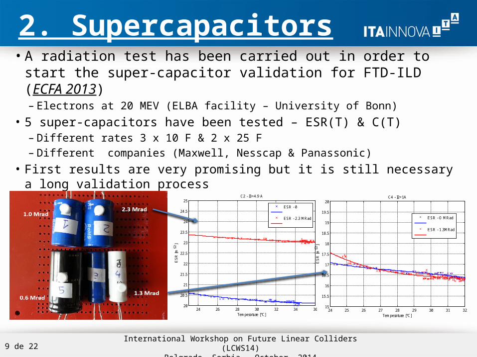
2. Supercapacitors• A radiation test has been carried out in order to start the super-
capacitor validation for FTD-ILD (ECFA 2013)– Electrons at 20 MEV (ELBA facility – University of Bonn)
• 5 super-capacitors have been tested – ESR(T) & C(T)– Different rates 3 x 10 F & 2 x 25 F– Different companies (Maxwell, Nesscap & Panassonic)
• First results are very promising but it is still necessary a long validation process
9 de 22International Workshop on Future Linear Colliders (LCWS14)
Belgrade, Serbia, October 2014
24 26 28 30 32 34 3620
20.5
21
21.5
22
22.5
23
23.5
24
24.5
25
Temperature [ºC]
ES
R [
m
]
C2 - I3=4.9 A
ESR - 0
ESR - 2.3 MRad
24 25 26 27 28 29 30 31 3215
15.5
16
16.5
17
17.5
18
18.5
19
19.5
20
Temperature [ºC]E
SR
[m
]
C4 - I2=1A
ESR - O MRad
ESR - 1.3MRad

3. Supercapacitor based PS
• The main elements of this topology are:–Supercapacitors:
• Pulse power – Transients locally–LV regulators:
• Stabilize FEE voltage–Current source :
• Controls super-capacitor voltage
10 de 22International Workshop on Future Linear Colliders (LCWS14)
Belgrade, Serbia, October 2014

3. Supercapacitor based PS
11 de 22International Workshop on Future Linear Colliders (LCWS14)
Belgrade, Serbia, October 2014
FTD +6
Time
0s 0.1s 0.2s 0.3s 0.4s 0.5s 0.6s 0.7s 0.8s 0.9s 1.0sI(R17)
0A
5A
10A
14A
Time
0s 0.1s 0.2s 0.3s 0.4s 0.5s 0.6s 0.7s 0.8s 0.9s 1.0sI(R19)
0A
5A
10A
14A
Time
0s 0.1s 0.2s 0.3s 0.4s 0.5s 0.6s 0.7s 0.8s 0.9s 1.0sI(C17)
0A
5A
10A
14A
Time
0s 0.1s 0.2s 0.3s 0.4s 0.5s 0.6s 0.7s 0.8s 0.9s 1.0sV(R6:1) V(R10:1) V(R12:2)
0V
1.0V
2.0V
3.0V
4.0V
5.0V

3. Supercapacitor based PS• The high capacitance has two advantages:
– It will protects the system in case mains failure – Similar to UPS• It helps shutdown the system in a controlled way.
– The dynamic response of primary power unit may be very slow• Remote regulation of the supercap voltage will be easy
12 de 22International Workshop on Future Linear Colliders (LCWS14)
Belgrade, Serbia, October 2014
Time
0s 1s 2s 3s 4s 5s 6s 7s 8s 9s 10sV(R17:2) V(R6:1) V(R10:1) -I(I10)
0
1.0
2.0
3.0
4.0
5.0
• The duration of the shut-down capability will depends on :• Capacitance • Voltage

4. FTD-ILD power group prototype• A real prototype of 1 Group of FTD sub-detector (FTD +6) has been
developed– 4 load boards - It simulates the FEE (hybrid) per petal– 2 Super-capacitors (several distance to Dummy loads – 50cm /10cm)– 1CF structure – It has been developed by FERMILAB–CMS Tracker II– Ip=13.5A – Isb =2.7A (Per petal – Ip=3.4A / Isb=0.7A)– Vsc = 4.2 V / Vinp=4V
13 de 22International Workshop on Future Linear Colliders (LCWS14)
Belgrade, Serbia, October 2014

4. FTD-ILD power group prototype• An ILC-FEE emulator has been
designed– Testing points– 3 LV regulators
• 2x1.5V / 1x2.5V– Pulse load: 3 x (2 resistors)– 3 x MOSFET– Driven by Texas Instruments CB
14 de 22International Workshop on Future Linear Colliders (LCWS14)
Belgrade, Serbia, October 2014
Operation condition = Simulation
5ms(2.5%)
T= 200ms

4. FTD-ILD power group prototype
15 de 22International Workshop on Future Linear Colliders (LCWS14)
Belgrade, Serbia, October 2014

4. FTD-ILD power group prototype
16 de 22International Workshop on Future Linear Colliders (LCWS14)
Belgrade, Serbia, October 2014
0 0.1 0.2 0.3 0.4 0.5 0.6 0.7 0.8 0.9 10
0.5
1
1.5
2
2.5
3
3.5
4
4.5
5
Time [s]
Curr
ent
[A]
/ V
oltage [
V]
Ip
Vsc
0 0.1 0.2 0.3 0.4 0.5 0.6 0.7 0.8 0.9 11
1.5
2
2.5
3
3.5
4
4.5
Time [s]
Voltage [
V]
Vbus
VoutREG1VoutREG2
0 0.1 0.2 0.3 0.4 0.5 0.6 0.7 0.8 0.9 10
2
4
6
8
10
12
14
Time [s]
Cur
rent
[A
]
Ipulse

4. FTD-ILD power group prototype
17 de 22International Workshop on Future Linear Colliders (LCWS14)
Belgrade, Serbia, October 2014
TRANSIENTS

4. FTD-ILD power group prototype
18 de 22International Workshop on Future Linear Colliders (LCWS14)
Belgrade, Serbia, October 2014
Regulator Transient
& Cable inductance

4. FTD-ILD power group prototype
19 de 22International Workshop on Future Linear Colliders (LCWS14)
Belgrade, Serbia, October 2014
T=4s
T=2s
LVReg1.5V LVReg2.5V
Major Fault – UPS capability

4.1 FTD-ILD power group prototype:Power dissipation test
• A very simple temperature test has been performed• Temperature sensors were installed on each board:
– One Termistor (PTC) per LV regulator– Temperature is processed by the control board
• A fan has been installed on one side of the CF structure– It has been switched on /off
• Systems were running more than 3 hours• Baseline Temperature : 21ºC
20 de 22International Workshop on Future Linear Colliders (LCWS14)
Belgrade, Serbia, October 2014
P2 P1P4P3

0 10 20 30 40 50 60 7020
25
30
35
40
45
50
55
60
Time [min]
Tem
p [
ºC]
P1-TReg25
P2-TReg25P3-TReg25
P4-TReg25
4.1 FTD-ILD power group prototype:Power dissipation test
• LVReg (1.5V) dissipates more power than LV (2.5V)• From the point of view of electronics, “this prototype” does not need to be
cooled (resistances dissipate power too)• Not Cooled: Tmax(P1)≈51ºC (ΔT ≈ 30ºC) / Tmin(P3)≈ 46ºC (ΔT ≈ 25ºC) • Cooled: Tmax(P2)≈34ºC (ΔT ≈ 13ºC) / Tmin(P3)≈ 25ºC (ΔT ≈ 4ºC) • Pulsing effect is very small from the point of view temperature
21 de 22International Workshop on Future Linear Colliders (LCWS14)
Belgrade, Serbia, October 2014
0 10 20 30 40 50 60 7020
25
30
35
40
45
50
55
60
Time [min]
Tem
p [º
C]
P1-TReg15
P2-TReg15P3-TReg15
P4-TReg15
Fan onFan off
Fan off
Fan on

5. Conclusions• A general overview of the supercapacitor based power
supply distribution system for FTD-ILD has been presented• Main characteristics and key elements have been shown
– Operation condition ( regulation , pulsing , supercapacitors..)
• Supercapacitors fit quite well power pulsing requirements– Radiation hardness shows no stoppers
• It still requires a detail analysis
• A real prototype of 1 group has been developed and tested– Very good agreement with simulations
• Power dissipation aspects :– From electronics point of view, this system does not need to be cooled– The pulsing effect seems not to have a big impact
• The results are very promising but a long study of the system is required in order to define final specification22 de 22
International Workshop on Future Linear Colliders (LCWS14)Belgrade, Serbia, October 2014


