FTB-8120NGE/FTB-8130NGE Power Blazer Next-Generation Multiservice Test Modules · 2009-03-06 ·...
16
FTB-8120NGE/8130NGE Power Blazer NETWORK TESTING — TRANSPORT AND DATACOM NEXT-GENERATION MULTISERVICE TEST MODULES Fully integrated multiservice test solution supporting next-generation SONET/SDH, optical transport network (OTN), Ethernet and Fibre Channel test functions DS0/E0 to OC-192/STM-64/OTU2; 10 Mbit/s to 10 Gbit/s LAN/WAN as well as 1x, 2x, 4x and 10x Fibre Channel testing in the industry’s smallest form factor Fully integrated solution for assessing the performance of Ethernet transport networks, including RFC 2544, BER testing and multistream generation and analysis Comprehensive Fibre Channel test capabilities, including framed and unframed BERT, buffer-to-buffer credit estimation and round-trip latency measurements OTN forward error correction (FEC) and optical channel data unit (ODU) multiplex testing capabilities as per ITU-T G.709 Ethernet-over-SONET/SDH (EoS) testing via GFP, VCAT and LCAS software options Platform Compatibility FTB-400 Universal Test System FTB-200 Compact Platform Next-Generation Network Assessment
Transcript of FTB-8120NGE/FTB-8130NGE Power Blazer Next-Generation Multiservice Test Modules · 2009-03-06 ·...

FTB-8120NGE/8130NGE Power Blazer
NETWORK TESTING — TRANSPORT AND DATACOM
NEXT-GENERATION MULTISERVICE TEST MODULES
Fully integrated multiservice test solution supportingnext-generation SONET/SDH, optical transportnetwork (OTN), Ethernet and Fibre Channel testfunctions
DS0/E0 to OC-192/STM-64/OTU2; 10 Mbit/s to 10 Gbit/s LAN/WAN as well as 1x, 2x, 4x and 10x Fibre Channel testing in the industry’ssmallest form factor
Fully integrated solution for assessing the performance of Ethernettransport networks, including RFC 2544, BER testing and multistreamgeneration and analysis
Comprehensive Fibre Channel test capabilities, including framed and unframed BERT, buffer-to-buffer credit estimation and round-triplatency measurements
OTN forward error correction (FEC) and optical channel data unit(ODU) multiplex testing capabilities as per ITU-T G.709
Ethernet-over-SONET/SDH (EoS) testing via GFP, VCAT and LCASsoftware options
Platform Compatibility
FTB-400 Universal Test System
FTB-200 Compact Platform
Next-Generation Network Assessment
FTB-8120NGE/8130NGENext-Generation Multiservice Test Modules
The Choice for Integrated Multiservice Transport Testing The responsibilities of traditional SONET/SDH telecom field installation personnel have evolved over the last few years. With the adventof packet-aware SONET/SDH add-drop multiplexers—including multiservice transport platforms (MSTPs) and new reconfigurable add-drop multiplexers (ROADMs)—technicians must not only perform traditional SONET/SDH tests, but are now also responsible forverifying packet-based services such as Ethernet, 10 Gigabit Ethernet and Fiber Channel running over the same network elements.
This has resulted in a growing need for multitechnology test solutions to support the deployment, operation and maintenance of thesemultiservice platforms and the corresponding data-aware SONET/SDH networks.
EXFO's FTB-8120NGE (2.5/2.7 Gbit/s) and FTB-8130NGE (10/10.7Gbit/s) Power Blazer test modules have been designed tospecifically address such field commissioning and maintenance requirements, providing SONET/SDH, Ethernet and Fibre Chanel testfunctions in the industry’s smallest and most efficient form factor and setting a new standard for multiservice field testing.
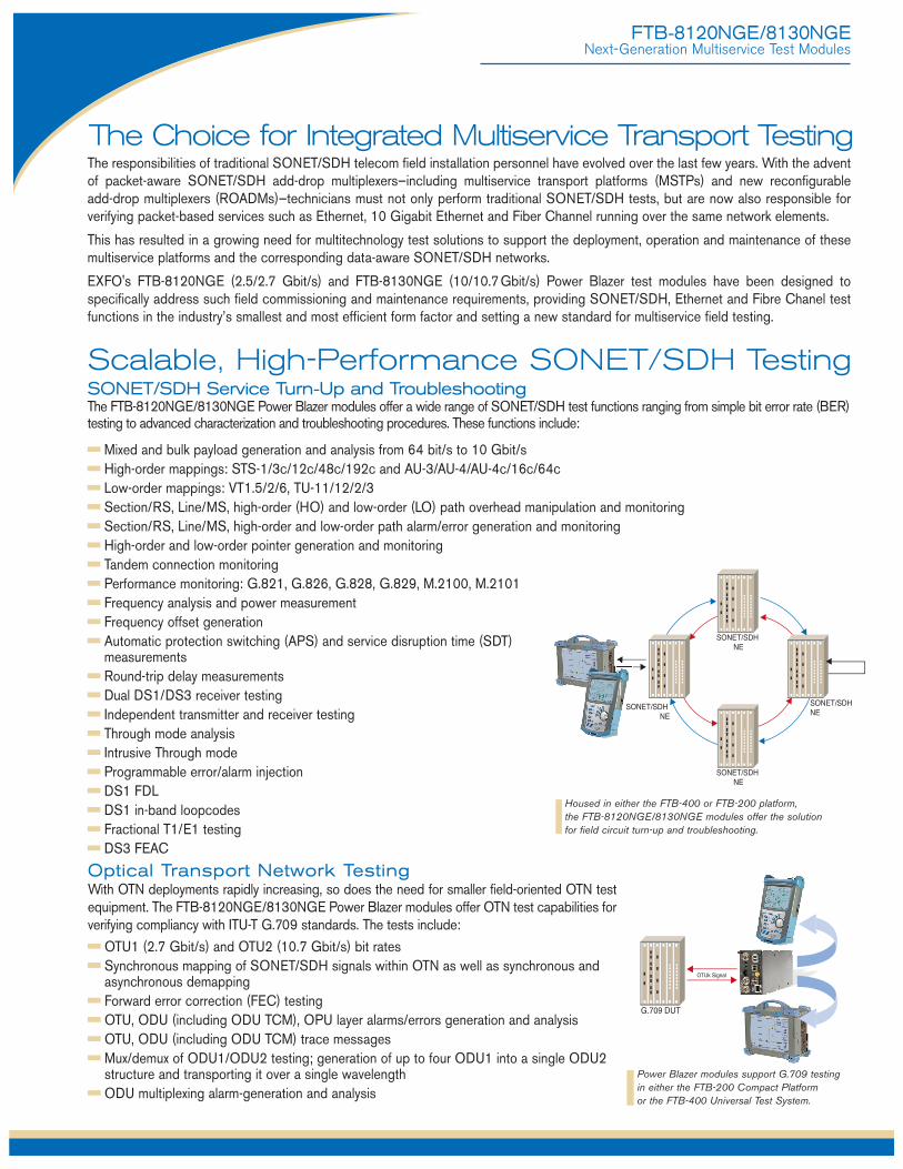
SONET/SDH Service Turn-Up and TroubleshootingThe FTB-8120NGE/8130NGE Power Blazer modules offer a wide range of SONET/SDH test functions ranging from simple bit error rate (BER)testing to advanced characterization and troubleshooting procedures. These functions include:
Mixed and bulk payload generation and analysis from 64 bit/s to 10 Gbit/sHigh-order mappings: STS-1/3c/12c/48c/192c and AU-3/AU-4/AU-4c/16c/64cLow-order mappings: VT1.5/2/6, TU-11/12/2/3Section/RS, Line/MS, high-order (HO) and low-order (LO) path overhead manipulation and monitoringSection/RS, Line/MS, high-order and low-order path alarm/error generation and monitoringHigh-order and low-order pointer generation and monitoringTandem connection monitoringPerformance monitoring: G.821, G.826, G.828, G.829, M.2100, M.2101Frequency analysis and power measurementFrequency offset generationAutomatic protection switching (APS) and service disruption time (SDT)measurementsRound-trip delay measurementsDual DS1/DS3 receiver testingIndependent transmitter and receiver testingThrough mode analysisIntrusive Through modeProgrammable error/alarm injectionDS1 FDLDS1 in-band loopcodesFractional T1/E1 testingDS3 FEAC
Housed in either the FTB-400 or FTB-200 platform, the FTB-8120NGE/8130NGE modules offer the solution for field circuit turn-up and troubleshooting.
SONET/SDH NE
SONET/SDH NE
SONET/SDH NE
SONET/SDH NE
Optical Transport Network TestingWith OTN deployments rapidly increasing, so does the need for smaller field-oriented OTN testequipment. The FTB-8120NGE/8130NGE Power Blazer modules offer OTN test capabilities forverifying compliancy with ITU-T G.709 standards. The tests include:
OTU1 (2.7 Gbit/s) and OTU2 (10.7 Gbit/s) bit ratesSynchronous mapping of SONET/SDH signals within OTN as well as synchronous andasynchronous demappingForward error correction (FEC) testingOTU, ODU (including ODU TCM), OPU layer alarms/errors generation and analysisOTU, ODU (including ODU TCM) trace messagesMux/demux of ODU1/ODU2 testing; generation of up to four ODU1 into a single ODU2structure and transporting it over a single wavelengthODU multiplexing alarm-generation and analysis
Power Blazer modules support G.709 testing in either the FTB-200 Compact Platform or the FTB-400 Universal Test System.
G.709 DUT
OTUk Signal
Scalable, High-Performance SONET/SDH Testing

FTB-8120NGE/8130NGENext-Generation Multiservice Test Modules
Next-Generation SONET/SDH TestingAvailable next-generation SONET/SDH test functionalities include generic framing procedure (GFP), virtual concatenation (VCAT)and link capacity adjustment scheme (LCAS). These options are available when the FTB-8120NGE/8130NGE are installed in theFTB-400 platform.
SmartMode: Real-Time Signal StructureDiscovery and MonitoringEXFO’s FTB-8120NGE/8130NGE Power Blazer modules support a uniquefeature called SmartMode. This provides users with full visibility of all high-order(STS/AU) and low-order (VT/TU) mixed mappings within the incomingSONET/SDH/OTN test signal.
SmartMode automatically discovers the signal structure of the OC-n/STM-nline including mixed mappings and virtual concatenation (VCAT) members. In addition to this in-depth multichannel visibility, SmartMode performs real-time monitoring of all discovered high-order paths and user-selected low-order paths simultaneously, providing users with the industry’s mostpowerful SONET/SDH/OTN multichannel monitoring and troubleshootingsolution. Real-time monitoring allows users to easily isolate network faults,saving valuable time and minimizing service disruption. SmartMode alsoprovides one-touch test case start, allowing users to quickly configure a desired test path and SmartMode specific reporting.
GFP
Generation and analysis of frame types(client management/client data)
Alarm/error generation and monitoring
Overhead manipulation and monitoring
Transmission and reception statisticsmonitoring
Supported over contiguous or VCATcontainers
VCAT
High-order and low-order VCATsupport
Simultaneous manipulation andmonitoring of each member
Alarm/error generation and monitoring
Sequence-indicator manipulation and processing
Group-summary monitoring
Differential delay analysis and insertion
LCAS
Emulation and analysis of LCASprotocol (Automatic and Manualmodes)
Source and sink state machinescontrol and monitoring
Real-time generation and monitoring of LCAS control fields
Real-time insertion and monitoring of LCAS alarms/errors
FTB-8120NGE/8130NGE SmartMode: multichannel signal discoverywith real-time alarm scan (shown in the FTB-400 user interface).

FTB-8120NGE/8130NGENext-Generation Multiservice Test Modules
Ethernet Performance Validation and ReliabilityEXFO’s FTB-8120NGE/8130NGE Power Blazers offer a wide range of Ethernet test functions aimed at performance validation andreliability testing.
InterfacesThese modules support multiple Ethernet interfaces,both electrical and optical:
ApplicationsThe FTB-8120NGE/8130NGE Power Blazer modules deliver thefeatures required to perform Ethernet service acceptance testing,namely RFC 2544 and BER testing.
RFC 2544 TestingIn cases where the Ethernet service is delivered via switchedtransport, the RFC 2544 measurements provide a baseline forservice providers to define SLAs with their customers. They enableservice providers to validate the quality of service (QoS) deliveredand can provide them with a tool to create value-added servicesthat can be measured and demonstrated to customers. For example, these tests provide performance statistics andcommissioning verification for virtual LANs (VLANs), virtual privatenetworks (VPNs) and transparent LAN services (TLS), all of whichuse Ethernet as an access technology.
The FTB-8120NGE/8130NGE Power Blazer modules come witha complete set of RFC 2544 test capabilities, including:
Throughput testingBurst (back-to-back) testingFrame loss analysisLatency measurement
BER TestingBecause the transparent transport of Ethernet services overphysical media is becoming common, Ethernet is increasinglycarried across a variety of layer 1 media over longer distances. Thiscreates a growing need for the certification of Ethernet transporton a bit-per-bit basis, which can be done using bit-error-ratetesting (BERT).
BERT uses a pseudo-random binary sequence (PRBS)encapsulated into an Ethernet frame, making it possible to go from a frame-based error measurement to a bit-error-rate measurement.This provides the bit-per-bit error count accuracy required for theacceptance testing of physical-medium transport systems.
In addition to BER testing, the FTB-8120NGE/8130NGE PowerBlazer modules also provide service disruption time (SDT)measurements.
Dual Test SetThe dual test set configuration allows the user to test asymmetricallywith two end ports and two test sets while being in direct control of only one test set. Two test sets are required for local/remotetesting, also known as head-to-head testing. The user operates one
test set, designated as the “local test set”, which controls the other,designated as the “remote test set”.
This configuration enables the user to carry out RFC 2544benchmark tests and achieve better visibility to the direction used(local to remote, remote to local, simultaneous) than by viewingroundtrip results. Configuring a test set in remote mode at the farend allows the user to detect all remote modules available for end-to-end RFC testing from the local unit, select one and sync up toit, then execute tests according to the desired direction with allresults of the far end being transmitted and shown on the near end.
Ethernet and IP QOS testingData services are making a significant shift toward supporting avariety of applications on the same network. This shift has fuelledthe need for QoS testing to ensure the condition and reliability ofservices. By providing the ability to configure different Ethernetand IP QoS parameters such as VLAN ID (802.1Q), VLAN priority(802.1p), VLAN stacking (802.1ad Q-in-Q), ToS and DSCP onmultiple streams, the FTB-8120NGE/8130NGE Power Blazermodules allow service providers to simulate and qualify differenttypes of applications running over their Ethernet network. The frameanalysis feature enables multi-stream traffic generation andanalysis as well as packet-jitter measurement (RFC 3393) andout-of-sequence testing. These measurements let serviceproviders efficiently benchmark transport networks when it comesto Ethernet services, carrying multiple applications such as tripleplay offerings (voice, video and data).
IP Test ToolsThe FTB-8120NGE/8130NGE Power Blazer modules providethe Ping and traceroute tools to execute connectivity tests at theIP layer.
ELECTRICAL OPTICAL10 Mbit/s 100 Mbit/s100 Mbit/s 1000 Mbit/s (GigE)1000 Mbit/s 10 Gbit/s (10 GigE)—FTB-8130NGE only
Networkunder test
Dual-test-set configuration (arrows show direction of traffic).

FTB-8120NGE/8130NGENext-Generation Multiservice Test Modules
Multiplatform Support and VersatilityThe FTB-8120NGE and FTB-8130NGE modules share a uniquearchitecture that allows them to be supported and interchangeable onboth the FTB-400 Universal Test System and the FTB-200 CompactPlatform. This cross-platform support provides users with addedflexibility to select the platform that best suits their testing needs. EXFOis the first and only test solution provider to offer this versatility, deliveringsingle to multi-application test solutions with the same hardware module,which in turn dramatically reduces capital expenditures.
Once inserted into the FTB-200 Compact Platform, the FTB-8120NGE/FTB-8130NGE Power Blazer modules deliver theindustry’s most compact integrated SONET/SDH, Ethernet and FibreChannel solution focused on field testing applications. Available withpowerful options—high-precision power meter, visual fault locator andfiber inspection probe—the FTB-200 provides all the critical test toolsrequired for day-to-day activities, eliminating the need to carry andmanage multiple test sets.
The FTB-400 platform configuration—used with either the four-slot (GP-404) or eight-slot (GP-408) module receptacle—provides userswith an all-in-one solution supporting a mix of SONET/SDH/OTN,Ethernet, Fibre Channel and optical-layer test modules, making it theindustry’s first truly integrated network testing platform. The resultingmodularity enables users to upgrade their systems in the field accordingto their testing needs. This multitechnology test platform is the idealsolution for field, central office and lab applications.
Product Option FlexibilityWith the FTB-8120NGE and FTB-8130NGE Power Blazer modules,users can purchase one or more next-generation options (e.g., GFP, VCAT, LCAS)and/or OTN options (OTU1, OTU2) via fieldupgrades to customize their configuration asnew needs arise. This avoids having toperform complete hardware and/or platformretrofits, therefore significantly decreasingcapital and training expenses.
In terms of Ethernet support, the FTB-8120NGE comes standard withEthernet testing capabilities up to GigE rate.On the FTB-8130NGE, users can select upto Gigabit Ethernet support or 10 GigabitEthernet support, or both.
Also, EXFO’s FTB-8120NGE supports1x/2x/4x Fibre Channel testing options, whilethe FTB-8130NGE supports 1x/2x/4x/10xFibre Channel testing options.
UnsurpassedConfiguration and Operational Flexibility
Fibre Channel NetworkIntegrity TestingEXFO’s FTB-8120NGE/8130NGE Power Blazer modules alsoallow comprehensive testing capabilities for Fibre Channelnetwork deployment.
InterfacesThese modules support multiple Fibre Channel interfaces:
ApplicationsSince most SANs cover large distances and Fibre Channelhas stringent performance attributes that must berespected, it is imperative to test at each phase of networkdeployment to ensure appropriate service levels. EXFO’sFTB-8120NGE/8130NGE Fibre Channel option providesfull wire-speed traffic generation at FC-0, FC-1 and FC-2logical layers, allowing BER testing for link integritymeasurements. Latency, buffer-to-buffer credit measurementsfor optimization, and login capabilities that enable end-to-endFibre Channel network testing features are also supported.
Buffer-to-Buffer Credit EstimationFlow control engine is the Fibre Channel buffer creditmechanism. This is a crucial configuration parameter foroptimal network performance. Usually, network administratorscalculate the value by taking the traveled distance and thedata rate into consideration; however, since latency issues arenot considered, poor accuracy is to be expected. The FTB-8120NGE/8130NGE modules are capable of estimatingbuffer-credit values with respect to latency by calculating thedistance according to the round-trip latency time.
INTERFACE RATE (Gbit/s)1x 1.06252x 2.1254x 4.2510x 10.51875

FTB-8120NGE/8130NGENext-Generation Multiservice Test Modules
DS1 E1/2M E2/8M E3/34M DS3/45M STS-1e/STM-0e/52M E4/140M STS-3e/STM-1e/155MTx Pulse Amplitude 2.4 to 3.6 V 3.0 V 2.37 V 2.37 V 1.0 ± 0.1 V 0.36 to 0.85 V 1.0 ± 0.1 Vpp 0.5 VTx Pulse Mask GR-499 G.703 G.703 G.703 G.703 GR-253 G.703
Figure 9.5 Figure 15 Figure 15 Figure 16 Figure 17 Figure 4-10/4-11 Figure 18/19Tx LBO Preamplification Power dBdsx
+0.6 dBdsx (0-133 ft) 0 to 225 ft 0 to 225 ft 0 to 225 ft+1.2 dBdsx (133-266 ft) 225 to 450 ft 255 to 450 ft+1.8 dBdsx (266-399 ft)+2.4 dBdsx (399-533 ft)+3.0 dBdsx (533-655 ft)
Cable Simulation Power dBdsx–22.5 dBdsx 450 to 900 (927) ft 450 to 900 (927) ft–15.0 dBdsx–7.5 dBdsx0 dBdsx
Rx Level Sensitivity For 772 kHz: For 1024 kHz: For 1024 kHz: For 4224 kHz: For 17.184 MHz: For 22.368 MHz: For 25.92 MHz: For 70 MHz: For 78 MHz:TERM: ≤ 26 dB (cable TERM: ≤ 6 dB TERM: ≤ 6 dB TERM: ≤ 6 dB TERM: ≤ 12 dB TERM: ≤ 10 dB TERM: ≤ 10 dB TERM: ≤ 12 dB TERM: ≤ 12.7 dB loss only) at 0 dBdsx Tx (cable loss only) (cable loss only) (cable loss only) (coaxial cable loss only) (cable loss only) (cable loss only) (coaxial cable loss only) (coaxial cable loss only)DSX-MON: ≤ 26 dB MON: ≤ 25 dB MON: ≤ 26 dB MON: ≤ 26 dB MON: ≤ 26 dB DSX-MON: ≤ 26.5 dB MON: ≤ 25 dB MON: ≤ 26 dB MON: ≤ 26 dB (20 dB resistive loss + (20 dB resistive loss (20 dB resistive loss + (20 dB resistive loss + (20 dB resistive loss + (21.5 dB resistive loss (20 dB resistive loss (20 dB resistive loss (20 dB resistive loss cable loss ≤ 6 dB) + cable loss ≤ 6 dB) cable loss ≤ 6 dB) cable loss ≤ 6 dB) cable loss ≤ 6 dB) + cable loss ≤ 5 dB) + cable loss ≤ 5 dB) + cable loss ≤ 6 dB) + cable loss ≤ 6 dB)Bridge: ≤ 6 dB Bridge: ≤ 6 dB Bridge: ≤ 6 dB (cable loss only) (cable loss only) (cable loss only)Note: measurement units = dBdsx Note: measurement units = dBm Note: measurement units = dBm Note: measurement units = dBm Note: measurement units = dBm Note: measurement units = dBm Note: measurement units = dBm Note: measurement units = dBm Note: measurement units = dBm
Transmit Bit Rate 1.544 Mbit/s ± 4.6 ppm 2.048 Mbit/s ± 4.6 ppm 2.048 Mbit/s ± 4.6 ppm 8.448 Mbit/s ± 4.6 ppm 34.368 Mbit/s ± 4.6 ppm 44.736 Mbit/s ± 4.6 ppm 51.84 Mbit/s ± 4.6 ppm 139.264 Mbit/s ±4.6 ppm 155.52 Mbit/s ± 4.6 ppmReceive Bit Rate 1.544 Mbit/s ± 140 ppm 2.048 Mbit/s ± 100 ppm 2.048 Mbit/s ± 100 ppm 8.448 Mbit/s ± 100 ppm 34.368 Mbit/s ± 100 ppm 44.736 Mbit/s ± 100 ppm 51.84 Mbit/s ± 100 ppm 139.264 Mbit/s ± 100 ppm 155.52 Mbit/s ± 100 ppmMeasurement Accuracy Frequency ±4.6 ppm ±4.6 ppm ±4.6 ppm ± 4.6 ppm ±4.6 ppm ±4.6 ppm ±4.6 ppm ±4.6 ppm ±4.6 ppm
Electrical Power DSX range: ±1.0 dB NORMAL: ±1.0 dB NORMAL: ±1.0 dB NORMAL: ±1.0 dB NORMAL: ±1.0 dB DSX range: ±1.0 dB DSX range: ±1.0 dB NORMAL: ±1.0 dB NORMAL: ±1.0 dBDSX-MON range: ± 2.0 dB MONITOR: ± 2.0 dB MONITOR: ± 2.0 dB MONITOR: ± 2.0 dB MONITOR: ±2.0 dB DSX-MON range: ±2.0 dB DSX-MON range: ±2.0 dB MONITOR: ±2.0 dB MONITOR: ±2.0 dB
Peak-to-Peak Voltage ±10 % down to 500 mVpp ± 10% down to 500 mVpp ± 10% down to 500 mVpp ± 10% down to 400 mVpp ±10% down to 200 mVpp ±10% down to 200 mVpp ±10% down to 200 mVpp ±10% down to 200 mVpp ±10% down to 200 mVppFrequency Offset Generation 1.544 Mbit/s ± 140 ppm 2.048 Mbit/s ± 70 ppm 2.048 Mbit/s ± 70 ppm 8.448 Mbit/s ± 50 ppm 34.368 Mbit/s ± 50 ppm 44.736 Mbit/s ± 50 ppm 51.84 Mbit/s ± 50 ppm 139.264 Mbit/s ± 50 ppm 155.52 Mbit/s ± 50 ppmIntrinsic Jitter (Tx) ANSI T1.403 section 6.3 G.823 section 5.1 G.823 section 5.1 G.823 section 5.1 G.823 section 5.1 GR-449 section 7.3 GR-253 section G.823 section 5.1 G.825 section 5.1
GR-499 section 7.3 G.751 section 2.3 (categories I and II) 5.6.2.2 (category II) GR-253 section 5.6.2.2 Input Jitter Tolerance AT&T PUB 62411 G.823 section 7.1 G.823 section 7.1 G.823 section 7.1 G.823 section 7.1 GR-449 section 7.3 GR-253 section 5.6.2.2 G.823 section 7.1 G.825 section 5.2
GR-499 section 7.3 (categories I and II) (category II) G.751 section 3.3 GR-253 section 5.6.2.3Line Coding AMI and B8ZS AMI and HDB3 AMI and HDB3 HDB3 HDB3 B3ZS B3ZS CMI CMIInput Impedance 100 ohms ± 5%, balanced 120 ohms ± 5%, balanced 75 ohms ± 5%, unbalanced 75 ohms ± 5%, unbalanced 75 ohms ± 5%, unbalanced 75 ohms ±5%, unbalanced 75 ohms ±5%, unbalanced 75 ohms ± 10%, unbalanced 75 ohms ± 5%, unbalanced(Resistive Termination)Connector Type BANTAM and RJ-48C BANTAM and RJ-48C BNC BNC BNC BNC BNC BNC BNC
STS-3eGR-253Figure 4-12/4-13/4-14
STM-1e/155MG.703Figure 4-14/22, 23
DS-3GR-499Figure 9-8
45-MG.703Figure 14
The following section provides detailed information on all supported SONET/SDH electrical interfaces.
External Clock DS1/1.5M External Clock E1/2M External Clock E1/2M Trigger 2 MHzTx Pulse Amplitude 2.4 to 3.6 V 3.0 V 2.37 V 0.75 to 1.5 VTx Pulse Mask GR-499 figure 9.5 G.703 figure 15 G.703 figure 15 G.703 figure 20
Typical power dBdsx+0.6 dBdsx (0-133 ft)
Tx LBO +1.2 dBdsx (133-266 ft)Preamplification +1.8 dBdsx (266-399 ft)
+2.4 dBdsx (399-533 ft)+3.0 dBdsx (533-655 ft)
Rx Level TERM: ≤ 6 dB (cable loss only) TERM: = ≤ 6 dB (cable loss only) TERM: = ≤ 6 dB (cable loss only) ≤ 6 dB (cable loss only)Sensivity (at 772 kHz for T1) DSX-MON: MON: ≤ 26 dB (20 dB resistive loss MON: ≤ 26 dB (resistive loss
≤ 26 dB (20 dB resistive loss + cable loss ≤ 6 dB) + cable loss ≤ 6 dB)+ cable loss ≤ 6 dB)Bridge: ≤ 6 dB (cable loss only) Bridge: ≤ 6 dB (cable loss only) Bridge: ≤ 6 dB (cable loss only)
Transmission Bit Rate 1.544 Mbit/s ± 4.6 ppm 2.048 Mbit/s ± 4.6 ppm 2.048 Mbit/s ± 4.6 ppmReception Bit Rate 1.544 Mbit/s ± 50 ppm 2.048 Mbit/s ± 50 ppm 2.048 Mbit/s ± 50 ppmIntrinsic Jitter (Tx) ANSI T1.403 section 6.3 G.823 G.823 G.703
GR-499 section 7.3 section 6.1 section 6.1 table 11Input Jitter AT&T PUB 62411 G.823 section 7.2 G.823 section 7.2Tolerance GR-499 SECTION 7.3 G.813 G.813Line Coding AMI and B8ZS AMI and HDB3 AMI and HDB3Input Impedance 75 ohms ± 5%, 75 ohms ± 5%, 75 ohms ± 5%, 75 ohms ± 5%,(Resistive Termination) unbalanced unbalanced unbalanced unbalancedConnector Type BNC a BNC a BNC BNC
10/100/1000 Base-T (Add/Drop)Compliance 10 Mbit/s: IEEE 802.3 section 14
100 Mbit/s: IEEE 802.3 section 251000 Mbit/s: IEEE 802.3 section 40
Connector RJ-45 EthernetGigabit Ethernet (Add/Drop)Interface/connector SFP/Dual LCCompliance 1000 Mbit/s: IEEE 802.3 Section 40 b
Wavelength/Max Tx level 850, 1310 nm/—3 dBm1550 nm/+5 dBm
Ref-Out InterfaceParameter ValueTx pulse amplitude 600 ± 150 mVppTransmission frequency
SONET/SDH/10 GigE WAN 10 GigE LANClock divider = 16 622.08 MHz 644.53 MHzClock divider = 32 311.04 MHz 322.266 MHzClock divider = 64 155.52 MHz 161.133 MHz
Output configuration AC coupledLoad impedance 50 ohmsMaximum cable length 3 metersConnector Type SMA
NOTES
a. Adaptation cable required for BANTAM.
b. SFP/XFP transceivers comply with IEC 60825 and 21 CFR 1040.10(except for deviations pursuant to Laser Notice 50, dated July, 2001), for Class 1 or 1M lasers.
SONET/SDH Electrical Interfaces
SYNCHRONISATION INTERFACES ETHERNET ADD/DROP INTERFACE
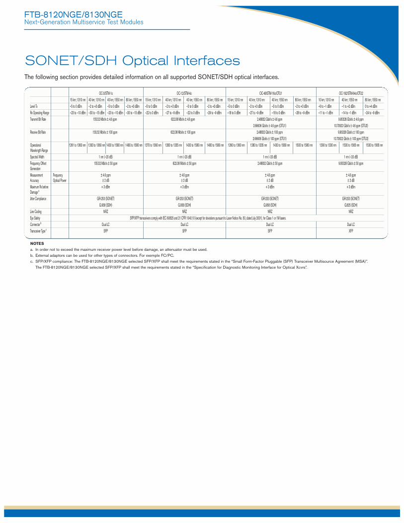
OC-3/STM-1o OC-12/STM-4o OC-48/STM-16o/OTU1 OC-192/STM-64o/OTU215 km; 1310 nm 40 km; 1310 nm 40 km; 1550 nm 80 km; 1550 nm 15 km; 1310 nm 40 km; 1310 nm 40 km; 1550 nm 80 km; 1550 nm 15 km; 1310 nm 40 km; 1310 nm 40 km; 1550 nm 80 km; 1550 nm 10 km; 1310 nm 40 km; 1550 nm 80 km; 1550 nm
Level Tx –5 to 0 dBm –2 to +3 dBm –5 to 0 dBm –2 to +3 dBm –5 to 0 dBm –2 to +3 dBm –5 to 0 dBm –2 to +3 dBm –5 to 0 dBm –2 to +3 dBm –5 to 0 dBm –2 to +3 dBm –6 to –1 dBm –1 to +2 dBm 0 to +4 dBmRx Operating Range –23 to –10 dBm –30 to –15 dBm –23 to –10 dBm –30 to –15 dBm –22 to 0 dBm –27 to –9 dBm –22 to 0 dBm –29 to –9 dBm –18 to 0 dBm –27 to –9 dBm –18 to 0 dBm –28 to –9 dBm –11 to –1 dBm –14 to –1 dBm –24 to –9 dBm Transmit Bit Rate 155.52 Mbit/s ± 4.6 ppm 622.08 Mbit/s ± 4.6 ppm 2.48832 Gbit/s ± 4.6 ppm 9.95328 Gbit/s ± 4.6 ppm
2.66606 Gbit/s ± 4.6 ppm (OTU1) 10.70922 Gbit/s ± 4.6 ppm (OTU2)Receive Bit Rate 155.52 Mbit/s ± 100 ppm 622.08 Mbit/s ± 100 ppm 2.48832 Gbit/s ± 100 ppm 9.95328 Gbit/s ± 100 ppm
2.66606 Gbit/s ± 100 ppm (OTU1) 10.70922 Gbit/s ± 100 ppm (OTU2)Operational 1261 to 1360 nm 1263 to 1360 nm 1430 to 1580 nm 1480 to 1580 nm 1270 to 1360 nm 1280 to 1335 nm 1430 to 1580 nm 1480 to 1580 nm 1260 to 1360 nm 1280 to 1335 nm 1430 to 1580 nm 1500 to 1580 nm 1290 to 1330 nm 1530 to 1565 nm 1530 to 1565 nmWavelength RangeSpectral Width 1 nm (–20 dB) 1 nm (–20 dB) 1 nm (–20 dB) 1 nm (–20 dB)Frequency Offset 155.52 Mbit/s ± 50 ppm 622.08 Mbit/s ± 50 ppm 2.48832 Gbit/s ± 50 ppm 9.95328 Gbit/s ± 50 ppmGenerationMeasurement Frequency ± 4.6 ppm ± 4.6 ppm ± 4.6 ppm ± 4.6 ppmAccuracy Optical Power ± 2 dB ± 2 dB ± 2 dB ± 2 dBMaximum Rx before + 3 dBm + 3 dBm + 3 dBm + 3 dBmDamage a
Jitter Compliance GR-253 (SONET) GR-253 (SONET) GR-253 (SONET) GR-253 (SONET)G.958 (SDH) G.958 (SDH) G.958 (SDH) G.825 (SDH)
Line Coding NRZ NRZ NRZ NRZEye Safety SFP/XFP transceivers comply with IEC 60825 and 21 CFR 1040.10 (except for deviations pursuant to Laser Notice No. 50, dated July 2001), for Class 1 or 1M lasers.Connector b Dual LC Dual LC Dual LC Dual LCTransceiver Type c SFP SFP SFP XFP
FTB-8120NGE/8130NGENext-Generation Multiservice Test Modules
The following section provides detailed information on all supported SONET/SDH optical interfaces.
NOTES
a. In order not to exceed the maximum receiver power level before damage, an attenuator must be used.
b. External adaptors can be used for other types of connectors. For exemple FC/PC.
c. SFP/XFP compliance: The FTB-8120NGE/8130NGE selected SFP/XFP shall meet the requirements stated in the “Small Form-Factor Pluggable (SFP) Transceiver Multisource Agreement (MSA)”.
The FTB-8120NGE/8130NGE selected SFP/XFP shall meet the requirements stated in the “Specification for Diagnostic Monitoring Interface for Optical Xcvrs”.
SONET/SDH Optical Interfaces

FTB-8120NGE/8130NGENext-Generation Multiservice Test Modules
SONET AND DSn SDH AND PDHOptical interfaces OC-3, OC-12, OC-48, OC-192 Optical interfaces STM-1, STM-4, STM-16, STM-64Available wavelengths (nm) 1310, 1550 Available wavelengths (nm) 1310, 1550Electrical interfaces DS1, DS3, STS-1e, STS-3e Electrical interfaces a 1.5M (DS1), 2M (E1), 8M (E2), 34M (E3),
45M (DS3), 140M (E4), STM-0e, STM-1eDS1 framing Unframed, SF, ESF 2M framing Unframed, PCM30, PCM31, PCM30 CRC-4,
PCM31 CRC-4DS3 framing Unframed, M13, C-bit parity 8M, 34M, 140M framing Unframed, framedClocking Internal, loop-timed, external (BITS), inter-module Clocking Internal, loop-timed, external (MTS/SETS),
2 MHz, inter-moduleMappings b Mappings b
VT1.5 Bulk, DS1, GFP c TU-11-AU-3, TU-11-AU-4 Bulk, 1.5M, GFP c
VT2 Bulk, E1, GFP c TU-12-AU-3, TU-12-AU-4 Bulk, 1.5M, 2M, GFP c
VT6 Bulk, GFP c TU-3-AU-4 Bulk, 34M, 45M, GFP c
STS-1 SPE Bulk, DS3, GFP c TU-2-AU-3, TU-2-AU-4 Bulk, GFP c
STS-3c/6c/9c/12c/24c/ Bulk, GFP c AU-4 Bulk, 140M, GFP c
48c/96c/192c, SPE AU-4-2c/3c/4c/8c/16c/32c/64c Bulk, GFP c
SONET overhead analysis A1, A2, J0, E1, F1, D1-D12, K1, K2, S1, M0, E2, J1, SDH overhead analysis A1, A2, J0, E1, F1, D1-D12, K1, K2, S1, M0, and manipulation E2, J1, C2, C2, G1, F2, H4, Z3, Z4, Z5, N1, N2 and manipulation G1, F2, F3, K3, N1, N2Error insertion Error insertionDS1 Framing bit, BPV, CRC-6, bit error E1 (2M) Bit error, FAS, CV, CRC-4, E-bitDS3 BPV, C-bit, F-bit, P-bit, FEBE, bit error E2 (8M), E3 (34M), E4 (140M) Bit error, FAS, CVSTS-1e, STS-3e Section BIP (B1), line BIP (B2), path BIP (B3), STM-0e, STM-1e RS-BIP (B1), MS-BIP (B2), HP-BIP (B3),
BIP-2, REI-L, REI-P, REI-V, BPV, bit error MS-REI, HP-REI, LP-BIP-2, LP-REI, bit error, CVOC-3, OC-12, Section BIP (B1), line BIP (B2), path BIP (B3), STM-1, STM-4, RS-BIP (B1), MS-BIP (B2), HP-BIP (B3), MS-REI, OC-48, OC-192 BIP-2, REI-L, REI-P, REI-V, FAS, bit error STM-16, STM-64 HP-REI, LP-BIP-2, LP-REI, FAS, bit errorError measurement Error measurementDS1 Framing bit, BPV, CRC-6, excess zeros, bit error E1 (2M) Bit error, FAS, CV, CRC-4, E-bitDS3 BPV, C-bit, F-bit, P-bit, FEBE, bit error E2 (8M), E3 (34M), E4 (140M) Bit error, FAS, CVSTS-1e, STS-3e Section BIP (B1), line BIP (B2), path BIP (B3), STM-0e, STM-1e RS-BIP (B1), MS-BIP (B2), HP-BIP (B3),
BIP-2, REI-L, REI-P, REI-V, BPV, bit error MS-REI, HP-REI, LP-BIP-2, LP-REI, bit error, CVOC-3, OC-12, Section BIP (B1), line BIP (B2), path BIP (B3), STM-1, STM-4, RS-BIP (B1), MS-BIP (B2), HP-BIP (B3), MS-REI, OC-48, OC-192 BIP-2, REI-L, REI-P, REI-V, FAS, bit error STM-16, STM-64 HP-REI, LP-BIP-2, LP-REI, FAS, bit errorAlarm insertion Alarm insertionDS1 LOS, RAI, AIS, OOF, pattern loss E1 (2M) LOS, LOS Mframe, LOS CRC Mframe, LOF,
AIS, TS16 AIS, RAI, RAI Mframe, pattern lossDS3 LOS, RDI, AIS, OOF, DS3 idle, pattern loss E2 (8M), E3 (34M), E4 (140M) LOS, LOF, RAI, AIS, pattern lossSTS-1e, STS-3e, OC-3, LOS, LOF, SEF, AIS-L, RDI-L, AIS-P, LOP-P, LOM, STM-0e, STM-1e, STM-1, LOS, LOF, OOF, MS-AIS, MS-RDI, AU-AIS,OC-12, OC-48, OC-192 PDI-P, RDI-P, ERDI-PCD, ERDI-PPD, ERDI-PSD, STM-4, STM-16, STM-64 AU-LOP, H4-LOM, HP-PDI, ERDI-PSD,
UNEQ-P, AIS-V, LOP-V, RDI-V, ERDI-VCD, ERDI-VPD, ERDI-PCD, ERDI-PPD, HP-UNEQ, TU-AIS, ERDI-VSD, RFI-V, UNEQ-V, pattern loss LP-RFI, LP-RDI, ERDI-VCD, ERDI-VPD,
ERDI-VSD, LP-RFI, LP-UNEQ, pattern lossAlarm detection Alarm detectionDS1 LOS, loss of clock (LOC), RAI, AIS, OOF, E1 (2M) LOS, LOS Mframe, LOS CRC Mframe, LOC,
pattern loss LOF, AIS, TS16 AIS, RAI, RAI Mframe, pattern lossDS3 LOS, LOC, RDI, AIS, OOF, DS3 idle, pattern loss E2 (8M), E3 (34M), E4 (140M) LOS, LOC, LOF, RAI, AIS, pattern lossSTS-1e, STS-3e, OC-3, LOS, LOC, LOF, SEF, TIM-S, AIS-L, RDI-L, AIS-P, STM-0e, STM-1e, STM-1, LOS, LOF, LOC, OOF, RS-TIM, MS-AIS, MS-RDI, OC-12, OC-48, OC-192 LOP-P, LOM, PDI-P, RDI-P, ERDI-PCD, ERDI-PPD, STM-4, STM-16, STM-64 AU-AIS, AU-LOP, H4-LOM, HP-RDI, ERDI-PSD,
ERDI-PSD, PLM/SLM-P, UNEQ-P, TIM-P, AIS-V, ERDI-PCD, ERDI-PPD, HP-PLM/SLM, HP-UNEQ, LOP-V, RDI-V, ERDI-VCD, ERDI-VCD, ERDI-VPD, HP-TIM, TU-AIS, LP-RFI, LP-RDI, ERDI-VPD, ERDI-VSD, RFI-V, UNEQ-V, TIM-V, PLM/SLM-V, ERDI-VSD, LP-RFI, LP-UNEQ, LP-TIM, LP-PLM/SLM,pattern loss pattern loss
Frequency alarm on all supported interfaces.Patterns PatternsDS0 2E9-1, 2E11-1, 2E20-1, 1100, 1010, 1111, 0000, E0 (64K) 2E9-1, 2E11-1, 2E20-1, 1100, 1010, 1111, 0000,
1-in-8, 1-in-16, 3-in-24, 32 bit programmable 1-in-8, 1-in-16, 3-in-24, 32 bit programmable(inverted or non-inverted), bit errors (inverted or non-inverted), bit errors
DS1 2E9-1, 2E11-1, 2E15-1, 2E20-1, 2E23-1, 2E31-1, E1 (2M) 2E9-1, 2E11-1, 2E15-1, 2E20-1, 2E23-1, 2E31-1, 1100, 1010, 1111, 0000, QRSS, 1-in-8, 1-in-16, 1100, 1010, 1111, 0000, 1-in-8, 1-in-16, 3-in-24, 3-in-24, 32 bit programmable (inverted or non-inverted), 32 bit programmable (inverted or non-inverted), bit errorsT1-DALY, 55-Octet, bit errors
DS3 2E9-1, 2E11-1, 2E15-1, 2E20-1, 2E23-1, 2E31-1, 1100, E2 (8M), E3 (34M), E4 (140M) 2E9-1, 2E11-1, 2E15-1, 2E20-1, 2E23-1, 2E31-1, 1100, 1010, 1111, 0000, 1-in-8, 1-in-16, 3-in-24 d, 1010, 1111, 0000, 1-in-8, 1-in-16, 3-in-24 d, 32 bit programmable (inverted or non-inverted), bit errors 32 bit programmable (inverted or non-inverted), bit errors
VT1.5/2/6 2E9-1, 2E11-1, 2E15-1, 2E20-1, 2E23-1, 2E31-1, TU-11/12/2/3 2E9-1, 2E11-1, 2E15-1, 2E20-1, 2E23-1, 2E31-1, 1100,1100, 1010, 1111, 0000, QRSS, 1-in-8, 1-in-16, 1010, 1111, 0000, 1-in-8, 1-in-16,32 bit programmable (inverted or non-inverted), bit errors 32 bit programmable (inverted or non-inverted), bit errors
STS-1, STS-3c/12c/48c/192c 2E9-1, 2E11-1, 2E15-1, 2E20-1, 2E23-1, 2E31-1, 1100, AU-3/AU-4/AU-4c/16c/64c 2E9-1, 2E11-1, 2E15-1, 2E20-1, 2E23-1, 2E31-1, 1100, 1010, 1111, 0000, 1-in-8, 1-in-16, 32 bit 1010, 1111, 0000, 1-in-8, 1-in-16, 32 bitprogrammable (inverted or non-inverted), bit errors programmable (inverted or non-inverted), bit errors
Pattern loss and bit error generation and analysis supported on all patterns.
NOTES
a. 1.5M (DS1) and 45M (DS3) interfaces described under SONET and DSn column.
b. VCAT mappings are also available. Please refer to the VCAT section of this document for details.
c. GFP supported only with purchase of GFP-F option.
d. Not supported for E4 (140M).
SONET/SDH Functional Specifications

FTB-8120NGE/8130NGENext-Generation Multiservice Test Modules
NEXT-GEN SONET NEXT-GEN SDHGeneric framing procedure (GFP) Generic framing procedure (GFP)Standards compliance As per ITU-T G.7041, and ANSI T1.105.02 Standards compliance As per ITU-T G.7041, G.707, and ANSI T1.105.02Payload PRBS pattern; Ethernet Payload PRBS pattern; EthernetEthernet add/drop Ability to add/drop Ethernet payload to/from GFP Ethernet add/drop Ability to add/drop Ethernet payload to/from GFP
mapped OC-n/OTU signal mapped STM-n/OTU signalError insertion Correctable core HEC, uncorrectable core HEC, Error insertion Correctable core HEC, uncorrectable core HEC,
correctable type HEC, uncorrectable type HEC, correctable type HEC, uncorrectable type HEC, correctable extension HEC, uncorrectable extension correctable extension HEC, uncorrectable extension HEC,HEC, payload FCS payload FCS
Error monitoring Correctable core HEC, uncorrectable core HEC, Error monitoring Correctable core HEC, uncorrectable core HEC, correctable type HEC, uncorrectable type HEC, correctable type HEC, uncorrectable type HEC, correctable extension HEC, uncorrectable extension correctable extension HEC, uncorrectable extension HEC, HEC, payload FCS payload FCS
Alarm insertion Loss of client signal (LOCS) and loss of client character Alarm insertion Loss of client signal (LOCS) and loss of client character synchronization (LOCCS) with configurable time interval synchronization (LOCCS) with configurable time interval between 10 and 1200 ms, and loss of frame delineation (LFD) between 10 and 1200 ms, and loss of frame delineation (LFD)
Alarm monitoring Loss of client signal (LOCS), loss of client character Alarm monitoring Loss of client signal (LOCS), loss of client character synchronization (LOCCS) and loss of frame delineation (LFD) synchronization (LOCCS) and loss of frame delineation (LFD)
Statistics Transmit: client data frames (including payload bytes), Statistics Transmit: client data frames (including payload bytes), client client management frames, total frames, idle frames, management frames, total frames, idle frames, GFP bandwidthGFP bandwidth usage (%), GFP mapping efficiency (%) usage (%), GFP mapping efficiency (%) Receive: client data frames (including payload bytes), Receive: client data frames (including payload bytes), client client management frames, total frames, idle (control) frames, management frames, total frames, idle (control) frames, reserved (control) frames, invalid frames, discarded frames, reserved (control) frames, invalid frames, discarded frames, EXI mismatches, UPI mismatches, CID mismatches, EXI mismatches, UPI mismatches, CID mismatches, GFP GFP bandwidth usage (%), GFP mapping efficiency (%) bandwidth usage (%), GFP mapping efficiency (%)
Header manipulation PTI, PFI, EXI, UPI, CID and spare (extension header) fields Header manipulation PTI, PFI, EXI, UPI, CID and spare (extension header) fieldsHeader monitoring PLI, PTI, PFI, EXI, UPI, CID, spare (extension header) fields, Header monitoring PLI, PTI, PFI, EXI, UPI, CID, spare (extension header) fields,
cHEC, tHEC, eHEC cHEC, tHEC, eHECVirtual concatenation (VCAT) Virtual concatenation (VCAT)Standards compliance Supports high-order and low-order virtual concatenation Standards compliance Supports high-order and low-order virtual concatenation
as per ANSI T1.105 as per ITU G.707Mappings High-order Mappings High-order
STS-1-Xv (X = 1 to 21) VC-3-Xv (X = 1 to 21)STS-3-Xv (X = 1 to 7) VC-4-Xv (X = 1 to 7)
Low-order Low-orderVT1.5-Xv (X = 1 to 64) VC-11-Xv (X = 1 to 64)VT-2-Xv (X = 1 to 64) VC-12-Xv (X = 1 to 64)
VC-3-Xv in AU-4 (X = 1 to 21)Alarm insertion LOM, OOM1, OOM2, SQM Alarm insertion LOM, OOM1, OOM2, SQM
VCAT and Path alarms can be generated independently on VCAT and Path alarms can be generated independently any member of a VCG on any member of a VCG
Alarm monitoring LOM, OOM1, OOM2, SQM, LOA Alarm monitoring LOM, OOM1, OOM2, SQM, LOADifferential delay Analysis Differential delay Analysis
Range: 0 to 256 ms Range: 0 to 256 msDisplay: numerical and graphical Display: numerical and graphical
Insertion InsertionRange: 0 to 256 ms Range: 0 to 256 ms
Sequence number Sequence range: 0 to 63 Sequence number Sequence range: 0 to 63manipulation and processing Sequence number monitoring: current AcSQ manipulation and processing Sequence number monitoring: current AcSQ
(accepted SQ) monitored against the ExSQ (expected SQ); (accepted SQ) monitored against the ExSQ (expected SQ); SQM alarm raised on mismatch SQM alarm raised on mismatch
SONET/SDH Functional Specifications (Cont’d)

FTB-8120NGE/8130NGENext-Generation Multiservice Test Modules
NEXT-GEN SONET/SDH (CONT’D)Link capacity adjustment scheme (LCAS)Standards compliance As per ITU G.7042; supported for both low-order
and high-order VCAT groupsTest functions Emulation of source and sink state machines
Automatic and manual control of source and sink state machinesIndependent overwrite capability at the source and sink for each memberAutomatic SQ management
Source state machine control Add/remove member(s)Configure: RS-ACK timeout, remote DUT, PLCT thresholdStatistics count: received RS-ACK, unexpected RS-ACKError/alarm generation: CRC errors, group ID (GID) mismatchError/alarm monitoring: loss of partial transport capacity, loss of total transport capacity, failure of protocol transmission, CRC errors, unexpected member status
Sink state machine control Add/remove member(s)Configure Hold-Off and Wait-to-Restore timers, PLCR thresholdToggle RS-ACKStatistics count: transmitted RS-ACKError/alarm generation: CRC errors, group ID (GID) mismatchError/alarm monitoring: loss of partial transport capacity, loss of total transport capacity, failure of protocol reception, CRC errors, unexpected member status
OTNStandards compliance ITU-T G.709, ITU G.798, ITU G.872Interfaces OTU1 (2.7 Gbit/s) and OTU2 (10.7 Gbit/s)Client types multiplexing a All supported SONET/SDH mappings (including next-generation GFP, VCAT, LCAS), NULL, PRBS (2E31-1), ODU1 into OTU2 OTU LayerErrors OTU-FAS, OTU-MFAS, OTU-BEI , OTU-BIP-8Alarms LOF, OOF, LOM, OOM, OTU-AIS, OTU-TIM, OTU-BDI, OTU-IAE, OTU-BIAETraces 64-bytes Trail Trace Identifier (TTI) as defined in ITU-T G.709ODU TCM LayerErrors TCMi-BIP-8, TCMi-BEI (i = 1 to 6)Alarms TCMi-AIS, TCMi-LTC, TCMi-OCI, TCMi-LCK, TCMi-TIM, TCMi-BDI, TCMi-IAE, TCMi-BIAETraces 64-bytes Trail Trace Identifier (TTI) as defined in ITU-T G.709ODU LayerErrors ODU-BIP-8, ODU-BEIAlarms ODU-AIS, ODU-OCI, ODU-LCK, ODU-TIM, ODU-BDI, ODU-FSF, ODU-BSF, ODU-FSD, ODU-BSDTraces Generates 64-bytes Trail Trace Identifier (TTI) as defined in ITU-T G.709FTFL b As defined in ITU-T G.709OPU LayerAlarm OPU-PLMPayload type (PT) label Generates and displays received PT value Forward Error Correction (FEC)Errors FEC-Correctable (Codeword), FEC-Uncorrectable (Codeword), FEC-Correctable (Symbol), FEC-Correctable (Bit),
and FEC-Stress (Codeword) ODU Multiplexing c
Alarms OPU-MSIM, ODU-LOFLOM
NOTES
a. Available with ODUMUX option.
b. Fault type and fault location.
c. Available on the FTB-8130NGE only.
SONET/SDH Functional Specifications (Cont’d)

FTB-8120NGE/8130NGENext-Generation Multiservice Test Modules
ADDITIONAL TEST AND MEASUREMENT FUNCTIONS
Power measurements Supports power measurements, displayed in dBm (dBdsx for DS1), for optical and electrical interfaces.Frequency measurements Supports clock frequency measurements (i.e., received frequency and deviation of the input signal clock from nominal frequency), displayed in ppm and b/s (bps),
for optical and electrical interfaces.Frequency offset generation Supports offsetting the clock of the transmitted signal on a selected interface to exercise clock recovery circuitry on network elements. Dual DSn receivers Supports two DS1 or DS3 receivers, allowing users to simultaneously monitor two directions of a circuit under test in parallel, resulting in quick isolation
of the source of errors.Performance monitoringThe following ITU-T recommendations, and corresponding performance monitoring parameters, are supported on the IQS-8100 product line.
ITU-T recommendation Performance monitoring statisticsG.821 ES, EFS, EC, SES, UAS, ESR, SESR, DMG.826 ES, EFS, EB, SES, BBE, UAS, ERS, SESR, BBERG.828 ES, EFS, EB, SES, BBE, SEP, UAS, ESR, SESR, BBER, SEPIG.829 ES, EFS, EB, SES, BBE, UAS, ESR, SESR, BBERM.2100 ES, SES, UAS, ESR, SESRM.2101 ES, SES, BBE, UAS, ESR, SESR, BBERPointer adjustment and analysisGeneration and analysis of HO/AU and LO/TU pointer adjustments as per GR-253, and ITU-T G.707Generation
• Pointer increment and decrement• Pointer jump with or without NDF• Pointer value
Analysis• Pointer increments• Pointer decrements• Pointer jumps (NDF, no NDF)• Pointer value and cumulative offset
Programmable error/alarm injection Ability to inject errors/alarms in the following modes: Manual, Constant Rate, Burst, Periodic Burst and Continuous.Service disruption time (SDT) measurements The service disruption time test tool measures the time during which there is a disruption of service due to the network switching from the active channels to the
backup channels.User-selectable triggers: all supported alarms and errors.Measurements: last disruption, shortest disruption, longest disruption, average disruption, total disruption, and service disruption count.
Round-trip delay (RTD) measurements The round-trip delay test tool measures the time required for a bit to travel from the FTB-8120NGE/8130NGE transmitter back to its receiver after crossing a far-endloopback. Measurements are supported on all supported FTB-8120NGE/8130NGE interfaces and mappings. a
Measurements: last RTD time, minimum, maximum, average, measurement count (no. of successful RTD tests), failed measurement count.APS message control and monitoring Ability to monitor and set up automatic protection switching messages (K1/K2 byte of SONET/SDH overhead).Synchronization status Ability to monitor and set up synchronization status messages (S1 byte of SONET/SDH overhead). Signal label control and monitoring Ability to monitor and set up payload signal labels (C2, V5 byte of SONET overhead).Through mode Ability to perform Through mode analysis of any incoming electrical (DSn, PDH) and optical line (OC-3/STM-1, OC-12/STM-4, OC-48/STM-16, OC-192/STM-64, OTU1
and OTU2).M13 mux/demux Ability to multiplex/demultiplex a DS1 signal into/from a DS3 signal. (Note: E1 to DS3 mux/demux available with G.747 software option.)DS1 FDL Support for DS1 Facility Data Link testing. DS1 loopcodes Support for generation of DS1 in-band loopcodes.DS3 FEAC Support for DS3 for-end alarms and loopback codewords.Tandem connection monitoring (TCM) b Tandem connection monitoring (TCM), Option 2 c, is used to monitor the performance of a subsection of a SONET/SDH path routed via different network providers.
The FTB-8120NGE/8130NGE supports transmitting and receiving alarms and errors on a TCM link; also, transmission and monitoring of the tandem connection (TC)trace can be generated to verify the connection between TCM equipment.Error generation: TC-IEC, TC-BIP, TC-REI, OEIError analysis: TC-IEC, TC-REI, OEI, TC-VIOLAlarm generation: TC-RDI, TC-UNEQ, ODI, TC-LTC, TC-IAISAlarm analysis: TC-TIM, TC-RDI, TC-UNEQ, ODI, TC-LTC, TC-IAIS
ADDITIONAL FEATURESScripting The built-in scripting engine and embedded macro-recorder provide a simple means of automating test cases and routines. Embedded scripting routines provide a
powerful means of creating advanced test scripts. Available only on the FTB-400.Reports Supports generation of test reports in .html, .csv, .txt, .pdf formats.
Contents of reports are customizable by the user.Power-up and restore In the event of a power failure to the unit, the active test configuration and test logger are saved and restored upon bootup.Store and load configurations Ability to store and load test configurations to/from non-volatile memory.Alarm hierarchy Alarms are displayed according to a hierarchy based on root cause. Secondary effects are not displayed. This hierarchy serves to facilitate alarm analysis.Configurable test views This allows users to customize their test views, i.e., to dynamically insert or remove test tabs/windows, in addition to creating new test windows, so as to accurately
match their testing needs. Available only on the FTB-400 user interface.Configurable test timer Provides the ability for a user to set pre-defined test start and stop times.Remote control Available with Windows-based remote management software known as Visual Guardian Lite (optional software package). This allows users to remotely monitor and
control the FTB-8120NGE/8130NGE modules via standard Ethernet connection.
NOTES
a. Except on OTN mappings.
b. HOP and LOP supported.
c. G.707 option 2.
SONET/SDH Functional Specifications (Cont’d)

FTB-8120NGE/8130NGENext-Generation Multiservice Test Modules
ELECTRICAL INTERFACES
10Base-T 100Base-T 1000Base-TTx bit rate 10 Mbit/s 125 Mbit/s 1 Gbit/sTx accuracy (ppm) ±100 ±100 ±100Rx bit rate 10 Mbit/s 125 Mbit/s 1 Gbit/sRx measurement accuracy (ppm) ±4.6 ±4.6 ±4.6Duplex mode Half and full duplex Half and full duplex Full duplex Jitter compliance IEEE 802.3 IEEE 802.3 IEEE 802.3Connector RJ-45 RJ-45 RJ-45Maximum reach (m) 100 100 100
100 Mbit/s AND GigE OPTICAL INTERFACES100Base-FX 100Base-LX 1000Base-SX 1000Base-LX 1000Base-ZX
Wavelength (nm) 1310 1310 850 1310 1550Tx level (dBm) —20 to —15 —15 to —8 —9 to —3 —9.5 to —3 0 to +5Rx level sensitivity (dBm) —31 —28 to —8 —20 —22 —22Maximum reach 2 km 15 km 550 m 10 km 80 kmTransmission bit rate (Gbit/s) 0.125 0.125 1.25 1.25 1.25Reception bit rate (Gbit/s) 0.125 0.125 1.25 1.25 1.25Tx operational wavelength range (nm) 1280 to 1380 1261 to 1360 830 to 860 1270 to 1360 1540 to 1570Measurement accuracy
Frequency (ppm) ±4.6 ±4.6 ±4.6 ±4.6 ±4.6Optical power (dB) ±2 ±2 ±2 ±2 ±2
Maximum Rx before damage (dBm) +3 +3 +6 +6 +6Jitter compliance ANSI X3.166 IEEE 802.3 IEEE 802.3 IEEE 802.3 IEEE 802.3Ethernet classification ANSI X3.166 IEEE 802.3 IEEE 802.3 IEEE 802.3 IEEE 802.3Laser type LED FP VCSEL FP DFBEye safety CLASS 1 CLASS 1 CLASS 1 CLASS 1 CLASS 1Connector LC LC LC LC LCTransceiver type SFP SFP SFP SFP SFP
10 GigE OPTICAL INTERFACES10GBASE-SW 10GBASE-SR 10GBASE-LW 10GBASE-LR 10GBASE-EW 10GBASE-ER
Wavelength (nm) 850 850 1310 1310 1550 1550 Multimode Multimode Singlemode Singlemode Singlemode Singlemode
Tx level (802.3ae-compliant) (dBm) –7.3 to –1 –7.3 to –1 –8.2 to +0.5 –8.2 to +0.5 –4.7 to +4.0 –4.7 to +4.0 Rx level sensitivity (dBm) –9.9 to –1.0 –9.9 to –1.0 –14.4 to +0.5 –14.4 to +0.5 –15.8 to –1.0 –15.8 to –1.0 Transmission bit rate 9.95328 Gbit/s ± 4.6 ppm a 10.3125 Gbit/s ± 4.6 ppm a 9.95328 Gbit/s ± 4.6 ppm a 10.3125 Gbit/s ± 4.6 ppm a 9.95328 Gbit/s ± 4.6 ppm a 10.3125 Gbit/s ± 4.6 ppm a
Reception bit rate 9.95328 Gbit/s ± 135 ppm 10.3125 Gbit/s ± 135 ppm 9.95328 Gbit/s ± 135 ppm 10.3125 Gbit/s ± 135 ppm 9.95328 Gbit/s ± 135 ppm 10.3125 Gbit/s ± 135 ppmTx operational wavelength range 840 to 860 840 to 860 1260 to 1355 1260 to 1355 1530 to 1565 1530 to 1565 (802.3ae-compliant) (nm)Measurement accuracy
Frequency (ppm) ±4.6 ±4.6 ±4.6 ±4.6 ±4.6 ±4.6 Optical power (dB) ±2 ±2 ±2 ±2 ±2 ±2
Maximum Rx before damage (dBm) 0 0 +1.5 +1.5 +4.0 +4.0 Jitter compliance IEEE 802.3ae IEEE 802.3ae IEEE 802.3ae IEEE 802.3ae IEEE 802.3ae IEEE 802.3aeEthernet classification IEEE 802.3ae IEEE 802.3ae IEEE 802.3ae IEEE 802.3ae IEEE 802.3ae IEEE 802.3aeLaser type VCSEL VCSEL DFB DFB EML EMLEye safety Class 1 laser; complies Class 1 laser; complies Class 1 laser; complies Class 1 laser; complies Class 1M laser; complies Class 1M laser; complies
with 21 CFR 1040.10 with 21 CFR 1040.10 with 21 CFR 1040.10 with 21 CFR 1040.10 with 21 CFR 1040.10 with 21 CFR 1040.10 and IEC 60825-1 and IEC 60825-1 and IEC 60825-1 and IEC 60825-1 and IEC 60825-1 and IEC 60825-1
Connector Duplex LC Duplex LC Duplex LC Duplex LC Duplex LC Duplex LCTransceiver type XFP XFP XFP XFP XFP XFP(compliant with XFP MSA)
Ethernet Interfaces
NOTE
a. When clocking is in internal mode.

FTB-8120NGE/8130NGENext-Generation Multiservice Test Modules
Ethernet Functional Specifications TESTING (10M TO GigE)RFC 2544 Throughput, back-to-back, frame loss and latency measurements according to RFC 2544.
Frame size: RFC-defined sizes, user-configurable.BERT Unframed, framed layer 1, framed layer 2 supported with or without VLAN Q-in-Q.Patterns (BERT) PRBS 2E9-1, PRBS 2E11-1, PRBS 2E15-1, PRBS 2E20-1, PRBS 2E23-1, PRBS 2E31-1, CRPAT, CSPAT, CJTPAT, Short CRTPAT,
Long CRTPAT and up to 10 user patterns. Capability to invert patterns.Error insertion (BERT) FCS, bit and symbol.Error measurement Jabber/giant, runt, undersize, oversize, FCS, symbol, idle, carrier sense, alignment, collision, late collision, excessive
collision, UDP and IP header checksum.Error measurement (BERT) Bit error, symbol error, idle error, bit mismatch 0, bit mismatch 1, performance monitoring (G.821 and G.826).Alarm insertion (BERT) LOS, pattern loss.Alarm detection LOS, link down, pattern loss, no traffic.Service disruption time Defect or No Traffic mode. Disruption time statistics include shortest, longest, last, average, total and count.measurement (BERT)VLAN stacking Capability to generate one stream with up to three layers of VLAN (including IEEE 802.1ad Q-in-Q tagged VLAN). Ethernet statistics Multicast, broadcast, unicast, N-unicast, frame size distribution, bandwidth, utilization, frame rate.Flow control statistics Pause time, last pause time, max. pause time, min. pause time, paused frames, abort frames, frames Tx, frames Rx.Advanced auto-negotiation Capability to auto-negotiate the rate, duplex and flow control capabilities with another Ethernet port.
Configurable auto-negociation parameters.Display of link partner capabilities.Fault injection: offline, link failure, auto-negotiation error.
Remote ENIU configuration Capability to support the operation, administration and maintenance (OAM) layer between an FTB-8120NGE/8130NGE and ADC ENIUs. This includes detection of ENIUs in the network and sending loopback commands.
Multistream generation Capability to transmit up to 10 streams. Configuration parameters are packet size, transmission mode (N-Frames, Burst, N-Burst, Ramp, N-Ramp and Continuous), MAC source/destination address, VLAN ID, VLAN priority, IP source/destination address, ToS field, DSCP field, TTL,UDP source/destination port and payload. (Available with Frame-Analyzer software option.)
Traffic analysis Capability to analyze the incoming traffic and provide statistics according to a set of up to 10 configurable filters. Filters can be configured for MACsource/destination address, VLAN ID, VLAN priority, IP source/destination address, ToS field, DSCP field, TCP source/destination port and UDPsource/destination port. VLAN filtering can be applied to any of the stacked VLAN layers. (Available with Frame-Analyzer software option.)
Ethernet statistics Multicast, broadcast, unicast, N-unicast, pause frame, frame size distribution, bandwidth, utilization, frame rate, frame loss, out-of-sequence framesand in-sequence frames. (Available with Frame-Analyzer software option.)
Jitter statistics generation Packet-jitter simulation—VoIP G.711, VoIP G.723.1, G.729, user-defined. Analysis: delay variation statistics (ms)—min., max., last, average, numberof samples and jitter measurement estimate. (Available with Frame-Analyzer software option.)
ADDITIONAL TEST AND MEASUREMENT FUNCTIONS (10M TO GigE)Power measurement Supports optical power measurement, displayed in dBm.Frequency measurement Supports clock frequency measurements (i.e., received frequency and deviation of the input signal clock from nominal frequency).Frequency offset measurement Range: ±120 ppm
Resolution: 1 ppmAccuracy: ±4.6 ppm
Dual test set Performs end-to-end, bidirectional performance testing (as required by leading standards bodies)—remote FTB-8120NGE/8130NGEcontrolled via the LAN connection under test.
DHCP client Capability to connect to a DHCP server to obtain its IP address and subnet mask for connecting on to the network.Smart Loopback Capability to return traffic to the local unit by swapping packet overhead up to layer 4 of the OSI stack.
TESTING (10 GigE)RFC 2544 Throughput, back-to-back, frame loss and latency measurements according to RFC 2544. Frame size: RFC-defined sizes, user-configurable.Patterns (BERT) PRBS 2E9-1, PRBS 2E11-1, PRBS 2E15-1, PRBS 2E20-1, PRBS 2E23-1, PRBS 2E31-1, and up to ten user patternsError insertion (BERT) FCS, bit, 64B/66B Block Error measurement LAN/WAN: jabber/giant, runt, undersize, oversize, FCS, 64B/66B Block
WAN: B1, B2, B3, REI-L, REI-PUDP, TCP and IP header checksum
Error measurement (BERT) Bit error, bit mismatch 0, bit mismatch 1, performance monitoring (G.821 and G.826)Alarm insertion LOS, link down, local fault, remote fault, pattern loss (BERT)
WAN: SEF, LOF, AIS-L, RDI-L, AIS-P, RDI-P, LCD-P, LOP-P, ERDI-PSD, ERDI-PCD, ERDI-PPD, UNEQ-PAlarm detection LOS, link down, local fault, remote fault, frequency offset, pattern loss (BERT)
WAN: SEF, LOF, AIS-L, RDI-L, AIS-P, RDI-P, LCD-P, LOP-P, ERDI-PSD, ERDI-PCD, ERDI-PPD, PLM-P, UNEQ-P, link (WIS)Service disruption time measurement (BERT) Defect or No Traffic mode. Disruption time statistics include shortest, longest, last, average, total and count.VLAN stacking Capability to generate one stream with up to three layers of VLAN (including IEEE802.1ad Q-in-Q tagged VLAN). Ethernet statistics Multicast, broadcast, unicast, N-unicast, frame size distribution, bandwidth, utilization, frame rate.Flow control statistics Pause time, last pause time, max. pause time, min. pause time, paused frames, abort frames, frames Tx, frames Rx.Multistream generation Capability to transmit up to 10 streams. Configuration parameters are packet size, transmission mode (N-Frames, Burst, N-Burst, Ramp,
N-Ramp and Continuous), MAC source/destination address, VLAN ID, VLAN priority, IP source/destination address, ToS field, DSCP field, TTL,UDP source/destination port and payload. (Available with Frame-Analyzer software option.)
Traffic analysis Capability to analyze the incoming traffic and provide statistics according to a set of up to 10 configurable filters. Filters can be configured for MACsource/destination address, VLAN ID, VLAN priority, IP source/destination address, ToS field, DSCP field, TCP source/destination port and UDPsource/destination port. VLAN filtering can be applied to any of the stacked VLAN layers. (Available with Frame-Analyzer software option.)
Ethernet statistics Multicast, broadcast, unicast, N-unicast, pause frame, frame size distribution, bandwidth, utilization, frame rate, frame loss, out-of-sequence framesand in-sequence frames. (Available with Frame-Analyzer software option.)
Jitter statistics generation Packet-jitter simulation—VoIP G.711, VoIP G.723.1, G.729, user-defined. Analysis: delay variation statistics (ms)—min., max., last, average, numberof samples and jitter measurement estimate. (Available with Frame-Analyzer software option.)
ADDITIONAL TEST AND MESUREMENT FUNCTIONS (10 GigE)Power measurement Supports optical power measurement, displayed in dBm.Frequency generation and measurement Supports clock frequency generation and measurements (i.e., received frequency and deviation of the input signal clock from nominal frequency).
Frequency offset generation:Range: ±50 ppmResolution: ±1 ppmAccuracy: ±4.6 ppm
Frequency offset measurement: Range: ±135 ppmResolution: ±1 ppmAccuracy: ±4.6 ppm
Signal label control and monitoring Ability to configure and monitor J0 Trace, J1 Trace and payload signal label C2 (WAN).Dual test set Performs end-to-end, bidirectional performance testing (as required by leading standards bodies)—remote FTB-8120NGE/8130NGE
controlled via the LAN connection under test.DHCP client Capability to connect to a DHCP server to obtain its IP address and subnet mask to connect to the network. Smart Loopback Capability to return traffic to the local unit by swapping packet overhead up to layer 4 of the OSI stack.
FTB-8120NGE/8130NGENext-Generation Multiservice Test Modules
Ethernet Functional Specifications (Cont’d)
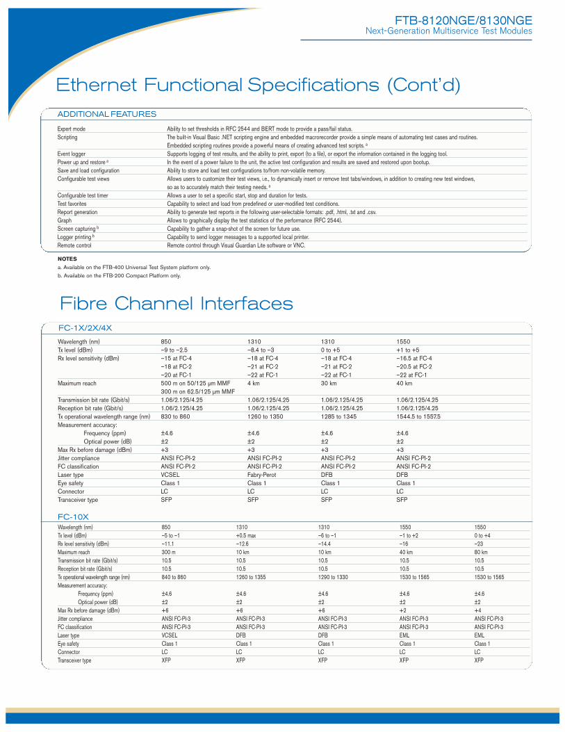
Expert mode Ability to set thresholds in RFC 2544 and BERT mode to provide a pass/fail status.Scripting The built-in Visual Basic .NET scripting engine and embedded macrorecorder provide a simple means of automating test cases and routines.
Embedded scripting routines provide a powerful means of creating advanced test scripts. a
Event logger Supports logging of test results, and the ability to print, export (to a file), or export the information contained in the logging tool.Power up and restore a In the event of a power failure to the unit, the active test configuration and results are saved and restored upon bootup.Save and load configuration Ability to store and load test configurations to/from non-volatile memory.Configurable test views Allows users to customize their test views, i.e., to dynamically insert or remove test tabs/windows, in addition to creating new test windows,
so as to accurately match their testing needs. a
Configurable test timer Allows a user to set a specific start, stop and duration for tests. Test favorites Capability to select and load from predefined or user-modified test conditions. Report generation Ability to generate test reports in the following user-selectable formats: .pdf, .html, .txt and .csv.Graph Allows to graphically display the test statistics of the performance (RFC 2544).Screen capturing b Capability to gather a snap-shot of the screen for future use.Logger printing b Capability to send logger messages to a supported local printer.Remote control Remote control through Visual Guardian Lite software or VNC.
ADDITIONAL FEATURES
NOTES
a. Available on the FTB-400 Universal Test System platform only.
b. Available on the FTB-200 Compact Platform only.
Wavelength (nm) 850 1310 1310 1550Tx level (dBm) –9 to –2.5 –8.4 to –3 0 to +5 +1 to +5Rx level sensitivity (dBm) –15 at FC-4 –18 at FC-4 –18 at FC-4 –16.5 at FC-4
–18 at FC-2 –21 at FC-2 –21 at FC-2 –20.5 at FC-2–20 at FC-1 –22 at FC-1 –22 at FC-1 –22 at FC-1
Maximum reach 500 m on 50/125 µm MMF 4 km 30 km 40 km300 m on 62.5/125 µm MMF
Transmission bit rate (Gbit/s) 1.06/2.125/4.25 1.06/2.125/4.25 1.06/2.125/4.25 1.06/2.125/4.25Reception bit rate (Gbit/s) 1.06/2.125/4.25 1.06/2.125/4.25 1.06/2.125/4.25 1.06/2.125/4.25Tx operational wavelength range (nm) 830 to 860 1260 to 1350 1285 to 1345 1544.5 to 1557.5Measurement accuracy:
Frequency (ppm) ±4.6 ±4.6 ±4.6 ±4.6Optical power (dB) ±2 ±2 ±2 ±2
Max Rx before damage (dBm) +3 +3 +3 +3Jitter compliance ANSI FC-PI-2 ANSI FC-PI-2 ANSI FC-PI-2 ANSI FC-PI-2 FC classification ANSI FC-PI-2 ANSI FC-PI-2 ANSI FC-PI-2 ANSI FC-PI-2 Laser type VCSEL Fabry-Perot DFB DFBEye safety Class 1 Class 1 Class 1 Class 1Connector LC LC LC LCTransceiver type SFP SFP SFP SFP
FC-10XWavelength (nm) 850 1310 1310 1550 1550Tx level (dBm) –5 to –1 +0.5 max –6 to –1 –1 to +2 0 to +4Rx level sensitivity (dBm) –11.1 –12.6 –14.4 –16 –23Maximum reach 300 m 10 km 10 km 40 km 80 kmTransmission bit rate (Gbit/s) 10.5 10.5 10.5 10.5 10.5Reception bit rate (Gbit/s) 10.5 10.5 10.5 10.5 10.5Tx operational wavelength range (nm) 840 to 860 1260 to 1355 1290 to 1330 1530 to 1565 1530 to 1565Measurement accuracy:
Frequency (ppm) ±4.6 ±4.6 ±4.6 ±4.6 ±4.6Optical power (dB) ±2 ±2 ±2 ±2 ±2
Max Rx before damage (dBm) +6 +6 +6 +2 +4Jitter compliance ANSI FC-PI-3 ANSI FC-PI-3 ANSI FC-PI-3 ANSI FC-PI-3 ANSI FC-PI-3FC classification ANSI FC-PI-3 ANSI FC-PI-3 ANSI FC-PI-3 ANSI FC-PI-3 ANSI FC-PI-3Laser type VCSEL DFB DFB EML EMLEye safety Class 1 Class 1 Class 1 Class 1 Class 1Connector LC LC LC LC LCTransceiver type XFP XFP XFP XFP XFP
FC-1X/2X/4X
Fibre Channel Interfaces
FTB-8120NGE/8130NGENext-Generation Multiservice Test Modules
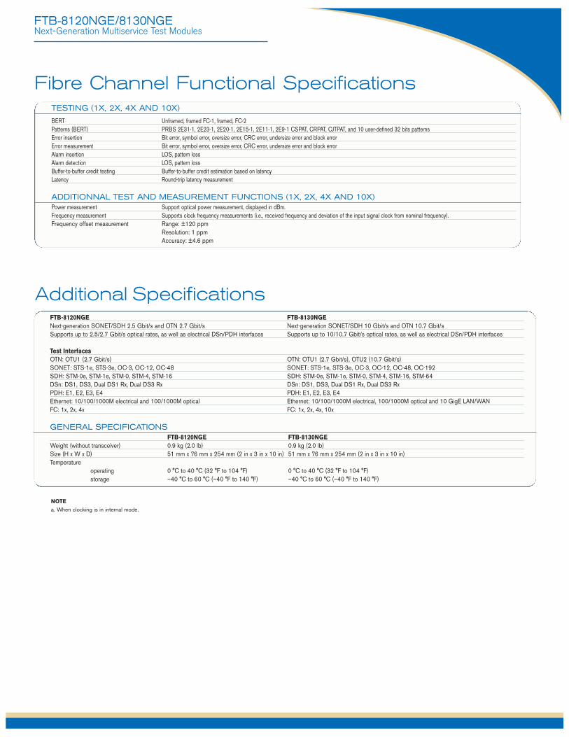
FTB-8120NGE FTB-8130NGENext-generation SONET/SDH 2.5 Gbit/s and OTN 2.7 Gbit/s Next-generation SONET/SDH 10 Gbit/s and OTN 10.7 Gbit/sSupports up to 2.5/2.7 Gbit/s optical rates, as well as electrical DSn/PDH interfaces Supports up to 10/10.7 Gbit/s optical rates, as well as electrical DSn/PDH interfaces
Test InterfacesOTN: OTU1 (2.7 Gbit/s) OTN: OTU1 (2.7 Gbit/s), OTU2 (10.7 Gbit/s)SONET: STS-1e, STS-3e, OC-3, OC-12, OC-48 SONET: STS-1e, STS-3e, OC-3, OC-12, OC-48, OC-192SDH: STM-0e, STM-1e, STM-0, STM-4, STM-16 SDH: STM-0e, STM-1e, STM-0, STM-4, STM-16, STM-64DSn: DS1, DS3, Dual DS1 Rx, Dual DS3 Rx DSn: DS1, DS3, Dual DS1 Rx, Dual DS3 RxPDH: E1, E2, E3, E4 PDH: E1, E2, E3, E4Ethernet: 10/100/1000M electrical and 100/1000M optical Ethernet: 10/100/1000M electrical, 100/1000M optical and 10 GigE LAN/WANFC: 1x, 2x, 4x FC: 1x, 2x, 4x, 10x
GENERAL SPECIFICATIONSFTB-8120NGE FTB-8130NGE
Weight (without transceiver) 0.9 kg (2.0 lb) 0.9 kg (2.0 lb)Size (H x W x D) 51 mm x 76 mm x 254 mm (2 in x 3 in x 10 in) 51 mm x 76 mm x 254 mm (2 in x 3 in x 10 in)Temperature
operating 0 °C to 40 °C (32 °F to 104 °F) 0 °C to 40 °C (32 °F to 104 °F)storage –40 °C to 60 °C (–40 °F to 140 °F) –40 °C to 60 °C (–40 °F to 140 °F)
Additional Specifications
NOTE
a. When clocking is in internal mode.
Fibre Channel Functional Specifications
BERT Unframed, framed FC-1, framed, FC-2Patterns (BERT) PRBS 2E31-1, 2E23-1, 2E20-1, 2E15-1, 2E11-1, 2E9-1 CSPAT, CRPAT, CJTPAT, and 10 user-defined 32 bits patternsError insertion Bit error, symbol error, oversize error, CRC error, undersize error and block errorError measurement Bit error, symbol error, oversize error, CRC error, undersize error and block errorAlarm insertion LOS, pattern lossAlarm detection LOS, pattern lossBuffer-to-buffer credit testing Buffer-to-buffer credit estimation based on latencyLatency Round-trip latency measurement
ADDITIONNAL TEST AND MEASUREMENT FUNCTIONS (1X, 2X, 4X AND 10X)Power measurement Support optical power measurement, displayed in dBm.Frequency measurement Supports clock frequency measurements (i.e., received frequency and deviation of the input signal clock from nominal frequency).Frequency offset measurement Range: ±120 ppm
Resolution: 1 ppmAccuracy: ±4.6 ppm
TESTING (1X, 2X, 4X AND 10X)
EXFO Corporate Headquarters > 400 Godin Avenue, Quebec City (Quebec) G1M 2K2 CANADA | Tel.: +1 418 683-0211 | Fax: +1 418 683-2170 | [email protected]
Toll-free: +1 800 663-3936 (USA and Canada) | www.EXFO.com
EXFO America 3701 Plano Parkway, Suite 160 Plano, TX 75075 USA Tel.: +1 800 663-3936 Fax: +1 972 836-0164 EXFO Asia 151 Chin Swee Road, #03-29 Manhattan House SINGAPORE 169876 Tel.: +65 6333 8241 Fax: +65 6333 8242EXFO China No. 88 Fuhua First Road Shenzhen 518048 P. R. CHINA Tel.: +86 (755) 8203 2300 Fax: +86 (755) 8203 2306 Central Tower, Room 801, Futian District Beijing New Century Hotel Office Tower, Room 1754-1755 Beijing 100044 P. R. CHINA Tel.: +86 (10) 6849 2738 Fax: +86 (10) 6849 2662 No. 6 Southern Capital Gym RoadEXFO Europe Omega Enterprise Park, Electron Way Chandlers Ford, Hampshire S053 4SE ENGLAND Tel.: +44 2380 246810 Fax: +44 2380 246801EXFO Service Assurance 285 Mill Road Chelmsford, MA 01824 USA Tel.: +1 978 367-5600 Fax: +1 978 367-5700
SPFTB-8120NGE/8130NGE.3AN © 2008 EXFO Electro-Optical Engineering Inc. All rights reserved. Printed in Canada 08/12
EXFO is certified ISO 9001 and attests to the quality of these products. This device complies with Part 15 of the FCC Rules. Operation is subject to the following two conditions: (1) this device may not cause harmful interference, and (2) this devicemust accept any interference received, including interference that may cause undesired operation. EXFO has made every effort to ensure that the information contained in this specification sheet is accurate. However, we accept no responsibility forany errors or omissions, and we reserve the right to modify design, characteristics and products at any time without obligation. Units of measurement in this document conform to SI standards and practices. In addition, all of EXFO’s manufacturedproducts are compliant with the European Union’s WEEE directive. For more information, please visit www.EXFO.com/recycle. Contact EXFO for prices and availability or to obtain the phone number of your local EXFO distributor.
For the most recent version of this spec sheet, please go to the EXFO website at http://www.EXFO.com/specs
In case of discrepancy, the Web version takes precedence over any printed literature.
FTB-8120NGE/8130NGENext-Generation Multiservice Test Modules
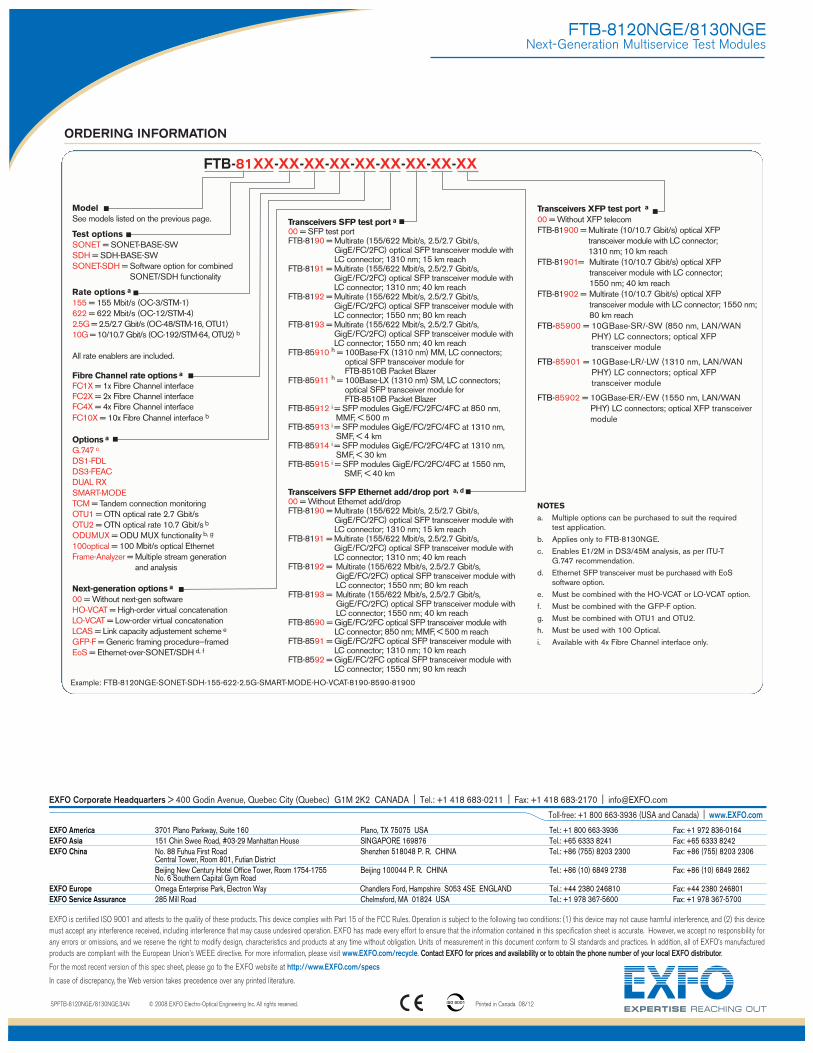
ORDERING INFORMATION
ModelSee models listed on the previous page.
Test optionsSONET = SONET-BASE-SWSDH = SDH-BASE-SWSONET-SDH = Software option for combined
SONET/SDH functionality
Rate options a
155 = 155 Mbit/s (OC-3/STM-1)622 = 622 Mbit/s (OC-12/STM-4)2.5G = 2.5/2.7 Gbit/s (OC-48/STM-16, OTU1)10G = 10/10.7 Gbit/s (OC-192/STM-64, OTU2) b
All rate enablers are included.
Fibre Channel rate options a
FC1X = 1x Fibre Channel interfaceFC2X = 2x Fibre Channel interfaceFC4X = 4x Fibre Channel interfaceFC10X = 10x Fibre Channel interface b
Options a
G.747 c
DS1-FDLDS3-FEACDUAL RXSMART-MODETCM = Tandem connection monitoringOTU1 = OTN optical rate 2.7 Gbit/sOTU2 = OTN optical rate 10.7 Gbit/s b
ODUMUX = ODU MUX functionality b, g
100optical = 100 Mbit/s optical EthernetFrame-Analyzer = Multiple stream generation
and analysis
Next-generation options a
00 = Without next-gen softwareHO-VCAT = High-order virtual concatenationLO-VCAT = Low-order virtual concatenationLCAS = Link capacity adjustement scheme e
GFP-F = Generic framing procedure—framedEoS = Ethernet-over-SONET/SDH d, f
Example: FTB-8120NGE-SONET-SDH-155-622-2.5G-SMART-MODE-HO-VCAT-8190-8590-81900
Transceivers SFP test port a
00 = SFP test portFTB-8190 = Multirate (155/622 Mbit/s, 2.5/2.7 Gbit/s,
GigE/FC/2FC) optical SFP transceiver module withLC connector; 1310 nm; 15 km reach
FTB-8191 = Multirate (155/622 Mbit/s, 2.5/2.7 Gbit/s,GigE/FC/2FC) optical SFP transceiver module withLC connector; 1310 nm; 40 km reach
FTB-8192 = Multirate (155/622 Mbit/s, 2.5/2.7 Gbit/s,GigE/FC/2FC) optical SFP transceiver module withLC connector; 1550 nm; 80 km reach
FTB-8193 = Multirate (155/622 Mbit/s, 2.5/2.7 Gbit/s,GigE/FC/2FC) optical SFP transceiver module withLC connector; 1550 nm; 40 km reach
FTB-85910 h = 100Base-FX (1310 nm) MM, LC connectors;optical SFP transceiver module for FTB-8510B Packet Blazer
FTB-85911 h = 100Base-LX (1310 nm) SM, LC connectors;optical SFP transceiver module for FTB-8510B Packet Blazer
FTB-85912 i = SFP modules GigE/FC/2FC/4FC at 850 nm, MMF, < 500 m
FTB-85913 i = SFP modules GigE/FC/2FC/4FC at 1310 nm, SMF, < 4 km
FTB-85914 i = SFP modules GigE/FC/2FC/4FC at 1310 nm, SMF, < 30 km
FTB-85915 i = SFP modules GigE/FC/2FC/4FC at 1550 nm, SMF, < 40 km
Transceivers SFP Ethernet add/drop port a, d
00 = Without Ethernet add/dropFTB-8190 = Multirate (155/622 Mbit/s, 2.5/2.7 Gbit/s,
GigE/FC/2FC) optical SFP transceiver module withLC connector; 1310 nm; 15 km reach
FTB-8191 = Multirate (155/622 Mbit/s, 2.5/2.7 Gbit/s,GigE/FC/2FC) optical SFP transceiver module withLC connector; 1310 nm; 40 km reach
FTB-8192 = Multirate (155/622 Mbit/s, 2.5/2.7 Gbit/s,GigE/FC/2FC) optical SFP transceiver module withLC connector; 1550 nm; 80 km reach
FTB-8193 = Multirate (155/622 Mbit/s, 2.5/2.7 Gbit/s,GigE/FC/2FC) optical SFP transceiver module withLC connector; 1550 nm; 40 km reach
FTB-8590 = GigE/FC/2FC optical SFP transceiver module with LC connector; 850 nm; MMF, < 500 m reach
FTB-8591 = GigE/FC/2FC optical SFP transceiver module with LC connector; 1310 nm; 10 km reach
FTB-8592 = GigE/FC/2FC optical SFP transceiver module with LC connector; 1550 nm; 90 km reach
Transceivers XFP test port a
00 = Without XFP telecomFTB-81900 = Multirate (10/10.7 Gbit/s) optical XFP
transceiver module with LC connector; 1310 nm; 10 km reach
FTB-81901= Multirate (10/10.7 Gbit/s) optical XFP transceiver module with LC connector; 1550 nm; 40 km reach
FTB-81902 = Multirate (10/10.7 Gbit/s) optical XFP transceiver module with LC connector; 1550 nm;80 km reach
FTB-85900 = 10GBase-SR/-SW (850 nm, LAN/WANPHY) LC connectors; optical XFPtransceiver module
FTB-85901 = 10GBase-LR/-LW (1310 nm, LAN/WANPHY) LC connectors; optical XFPtransceiver module
FTB-85902 = 10GBase-ER/-EW (1550 nm, LAN/WANPHY) LC connectors; optical XFP transceivermodule
FTB-81XX-XX-XX-XX-XX-XX-XX-XX-XX
NOTES
a. Multiple options can be purchased to suit the required test application.
b. Applies only to FTB-8130NGE.
c. Enables E1/2M in DS3/45M analysis, as per ITU-T G.747 recommendation.
d. Ethernet SFP transceiver must be purchased with EoSsoftware option.
e. Must be combined with the HO-VCAT or LO-VCAT option.
f. Must be combined with the GFP-F option.
g. Must be combined with OTU1 and OTU2.
h. Must be used with 100 Optical.
i. Available with 4x Fibre Channel interface only.