
ft E I k - Defense Technical Information Center · pu preliminary design of a modular unmanned elec...
220
PU PRELIMINARY DESIGN OF A MODULAR UNMANNED ELEC ft E I k RESR V RESE RCH VEH CLEJA N 1 8 1989' VOLUME ONE: SYSTEM DESIGN DOCUMENT DESIGN STUDY D -7Sl"ATEMENI A Approved P*r pIyc raleage( D i j u i bu ll c j- .7- - t e d " DEPARTMENT OF THE AIR FORCE AIR UNIVERSITY AIR FORCE INSTITUTE OF TECHNOLOGY - Wright-Patterson Air Force Base, Ohio 89 n
Transcript of ft E I k - Defense Technical Information Center · pu preliminary design of a modular unmanned elec...

PU
PRELIMINARY DESIGN OF A MODULAR UNMANNED ELEC
ft E I k
RESR VRESE RCH VEH CLEJA N 1 8 1989'VOLUME ONE: SYSTEM DESIGN DOCUMENT
DESIGN STUDY D
-7Sl"ATEMENI AApproved P*r pIyc raleage(
D i j u i bu ll c j- .7- - t e d "
DEPARTMENT OF THE AIR FORCE
AIR UNIVERSITY
AIR FORCE INSTITUTE OF TECHNOLOGY -
Wright-Patterson Air Force Base, Ohio
89 n

*l
AFIT/GSE/AA/88D-2
* DTICS§--ZECTE
JN1 8 1989
*C
PRELIMINARY DESIGN OF A MODULAR UNMANNEDD Tt C
RESEARCH VEHICLE gpINSPECTM
VOLUME ONE: SYSTEM DESIGN DOCUMENT
DESIGN STUDYAct
N TS I SAFIT/GSE/AA /88D-2 i-,L
D2
Approved for public release; distribution unlimited.
--- --- -

AFIT/GSE/AA/88D-2
PRELIMINARY DESIGN OF A MODULAR
UNMANNED RESEARCH VEHICLE
* VOLUME ONE: SYSTEM DESIGN DOCUMENT
DESIGN STUDY
* Presented to the Faculty of the School of Engineering
of the Air Force Institute of Technology
Air University
In Partial Fulfillment of the
Requirements for the Degree of
Master of Science
Christopher D. Hall, B.S., Captain, USAF
Richard L. Johnson, B.S.
Peter J. Lamatsch, B.S., Captain, USAF
Douglas A. McCabe, B.S., Captain, USAF
Paul J. Mueller, I1, B.S., Captain, USAF
Michael E. Paul, B.S., Captain, USAF
Letitia M. Pohl, B.S., Captain, USAF
* Graduate Systems Engineering
December 1988
Approved fnr public release; distribution unlimited.

Acknowledgments
We undertook the design of a Modular Unmanned Research Vehicle after we were presented
with the basic idea by Major Lanson Hudson from the Department of Aeronautics and Astronautics
at the Air Force Institute of Technology. This document describes the approach, analysis, and
results of the design study. The document is divided into three volumes: Volume One is the
System Design Document and contains the system level information; Volume Two, Subsystem
Technical Development, details the design of the various subsystems which make up the MURV;
and Volume Three contains the appendices.
We would like to thank our advisor, Major Stuart Kramer, for his encouragement and guidance
* throughout this effort. We also thank the other members of our committee for their contributions to
our work: Major Lanson Hudson, Lieutenant Colonel Paul King, and Dr. Curtis Spenny provided
many useful comments over the course of this design study.
• We received continual assistance from two offices of the Air Force Wright Aeronautical Labo-
ratory (AFWAL): the Unmanned Research Vehicle Branch (AFWAL/FIGL), and the Performance
Analysis Branch (AFWAL/TXAD). In particular, we would like to thank Bill Lindsay, Dave Ham-
* mond, and Max Zink for their help in completing this project.
Last, but certainly not least, we express our deepest gratitude to our families for their
love, support, and patience during these trying months: Rhoda and Duncan Hall, Joan Johnson,
Stephanie Lamatsch, Doris Paul, Ed Pohl, and Mike McCabe.
For additional information concerning this project, contact Major Stuart Kramer at AFIT/ENY,
Wright-Patterson AFB, OH 45433. AUTOVON 785-6998 or (513) 255-6998.
ii

Table of Contents
Page
VOLUME ONE: SYSTEM DESIGN DOCUMENT
Acknowledgm ents .... ............................ ....... iii
Table of Contents . . .. .. ... .. .... .. . .... ... . ... ... .... . .. iv
List of Figures ......................................... xi
SList of Tables ......................................... xiii
List of Sym bols . . . . . . . . . . . . . . . . . . . . . . . . . . . . . . . . . . . . . . . . xiv
* List of Abbreviations ..................................... xix
A bstract . . .. . . .. . . . .. . . .. . . . .. . . .. . . . .. . .. . . . . .. . . .. xxii
1. Introduction ................................................ 1-1
1.1 Background and Problem Statement ......................... 1-1
1.2 Scope ........... .................................... 1-3
1.2.1 The First Iteration ........ ........................ 1-3
1.2.2 Review of Current Literature ...... .................. 1-9
1.2.3 Level of Detail of Design ...... ..................... 1-13
1.3 Thesis Overview ......... .............................. 1-14
II. Development Design Criteria ......... ............................. 2-1
2.1 Overview of Systematic Systems Approach .................... 2-1
2.2 Revised Problem Statement ........ ........................ 2-5
2.2.1 Needs ......... ............................... 2-6
2.2.2 Constraints ......... ............................ 2-7
2.2.3 Value System Design .............................. 2-8
* 2.2.4 Subsystem Design Objectives ........................ 2-10
iv

Page
11l. Conceptual Design Phase .. .. .. ... ... .... ... ... ... ... ...... 3-1
03.1 Identification of Primary Design Drivers .. .. .. .. ... ... ...... 3-1
3.1.1 Modularity .. .. .. ... ... ... ... ... .... ....... 3-2
3.1.2 Data Acquisition. .. .. .. ... ... ... ... .... ..... 3-3
*3.1.3 Superinaneuverability .. .. .. ... ... ... ... ........ 3-4
3.1.4 Summnary. .. .. .. ... ... ... .... ... ... ...... 3-6
3.2 Selection of the Fighter-Like Concept .. .. .. ... .... ... ..... 3-6
3.2.1 Engine Type Restriction .. .. .. .. ... ... ... ........ 3-7
3.2.2 General Layout .. .. .. .. ... ... ... ... .... ..... 3-7
3.2.3 MURV General Sizing. .. .. .. ... ... ... ... ...... 3-T
3.3 Summary .. .. .. ... ... ... ... ... ... .... ... ...... 3-8
IV. Performance Objectives. .. .. ... ... ... ... ... ... ... .... ..... 4-1
4.1 Introduction .. .. .. .... ... ... ... ... ... ... ........ 4-1
*4.2 Experimental Requirements .. .. .. .. ... ... .... ... ...... 4-1
4.2.1 Maneuvering .. .. .. ... ... ... ... ... .... ..... 4-2
4.2.2 Integrated Controls. .. .. ... ... ... ... ... ...... 4-4
4.2.3 Propulsion/Airframe Integration. .. .. .. ... .... ..... 4-4
4.2.4 Configuration Trade Studies. .. .. .. .. ... ... ........ 4-5
4.2.5 Testing Special Hardware. .. .. .. ... ... ... ........ 4-5
4.2.6 Evaluation of Test Techniques. .. .. ... ... ... ...... 4-5
4.2.7 Dynamic Aeroelastic and Aerothermoelastic Testing ..... 4-5
4.3 Data Collection Requirements .. .. .. .. ... ... ... ... ...... 4-6
4.3.1 Required Parameters .. .. .. .. ... ... ... ... ...... 4-7
4.3.2 Summary of Data Requirements. .. .. ... ... ... ..... 4-11
4.4 Performance Objectives .. .. .. ... ... ... ... ... .... ... 4-12
4.4.1 The Herbst Maneuver and Supermaneuverability .. .. .. ... 4-14
*4.4.2 Range Performance. .. .. ... ... ... ... .... ..... 4-16
v

0
Page
4.4.3 Takeoff and Landing Performance ..... ............... 4-17
* 4.4.4 Summary of Performance Objectives ................... 4-21
4.5 Stability and Control Objectives ...... ..................... 4-21
4.5.1 Stability and Control Rules of Thumb ................. 4-22
* 4.5.2 Control Surface Design Guidelines .................... 4-25
4.5.3 Stability and Control Objectives ...... ................ 4-26
4.6 Dynamical Similarity ........ ............................ 4-27
* 4.7 Summary .......... .................................. 4-30
V. Preliminary Design .......... .................................. 5-1
5.1 External Arrangement and Vehicle Sising ...... ................ 5-1
* 5.1.1 Configuration Enhancements ...... .................. 5-2
5.1.2 The MURV-320 Preliminary Design ..... .............. 5-5
5.1.3 Aerodynamic Characteristics ...... .................. 5-5
• 5.1.4 Stability and Control Characteristics .................. .5-9
5.2 Propulsion System ........ ............................. 5-10
5.2.1 Turbojet Engine ........ ......................... 5-10
5.2.2 Preliminary Inlet Design ............................ 5-13
5.2.3 Nossle Considerations ....... ...................... 5-14
5.2.4 Fuel System Design ....... ....................... 5-16
5.2.5 Electrical Power system ...... ..................... 5-18
5.2.6 Propulsion System Summary ...... .................. 5-18
5.3 Flight Control System Design ....... ....................... 5-19
5.3.1 Mission Scenarios ................................ 5-20
5.3.2 Measurement and Discrete Data Requirements ............ 5-20
5.3.3 Control Surface Requirements ........................ 5-22
5.3.4 Flight Control System Architecture ..... .............. 5-24
5.3.5 FCS Design Summary ....... ...................... 5-30
vi

Page
5.4 Lau nch /Recovery System. .. .. .. ... ... .... ... ... ..... 5-30
*5.4.1 Launch System .. .. .. .. ... ... .... ... ... ..... 5-31
5.4.2 Recovery System .. .. .. .. ... ... .... ... ... ... 5-34
5.5 Data Acquisition System Design. .. .. .. .... ... ... ... ... 5-36
*5.5.1 System Description. .. .. .. .. ... .... ... ... ..... 5-37
5.5.2 Data Collection .. .. .. .. ... ... ... ... ... ...... 5-39
5.5.3 Signal Conditioning .. .. .. ... ... ... .... ... ... 5-41
5.5.4 Telemetry .. .. .. .. ... ... ... .... ... ... ..... 5-42
5.5.5 Data Processing and Recording. .. .. .. .. .... ... ... 5-43
5.5.6 Data Acquisition System Design Summary. .. .. ... ..... 5-45
5.6 Structural Design. .. .. .. .. ... ... ... .... ... ... ..... 5-45
5.6.1 Fuselage Structure. .. .. .. ... ... ... .... ... ... 5-45
5.6.2 Wing Design .. .. .. ... ... ... ... .... ... ..... 5-56
5.6.3 Empennage Design. .. .. .. .. .... ... ... ... ..... 5-58
5.6.4 Summary .. .. .. .. ... .... ... ... ... ... .... 5-60
5.7 Modularity .. .. .. ... ... ... ... ... .... ... ... ..... 5-61
5.7.1 Structural Modularity. .. .. .. ... ... ... .... ..... 5-61
05.7.2 Aero Shells. .. .. .. ... ... .... ... ... ... ..... 5-70
5.7.3 Electrical Modularity. .. .. ... ... ... ... .... ... 5-72
5.7.4 Internal Arrangement. .. .. .. ... .... ... ... ..... 5-72
*5.7.5 Application of Modularity Features into Baseline and Alternate
Configurations .. .. .. ... ... ... ... .... ... ... 5-75
5.8 Remote Cockpit .. .. .. ... ... ... .... ... ... ... ..... 5-82
5.8.1 Overall Layout .. .. .. .. .... ... ... ... ... .... 5-83
5.8.2 Description of Controls and Instruments .. .. .. .. ... ... 5-83
5.9 Tracking System .. .. .. ... ... ... ... ... ... .... ..... 5-90
5.10 Reliability Summary .. .. .. .. ... ... ... ... .... ... ... 5-91
vii

Page
5.10.1 Failure Modes and Effects Analysis ................... 5-91
* 5.10.2 Critical Items List ....... ........................ 5-96
VI. Implementation Recommendations ........ .......................... 6-1
6.1 External Arrangement and Vehicle Sizing ...... ................ 6-1
6.1.1 Refined Weight Estimate ....... .................... 6-1
6.1.2 External Arrangement ....... ...................... 6-1
6.2 Aerodynamics ......... ............................... 6-3
* 6.2.1 Computational Flow Analysis ........................ 6-3
6.2.2 Wind Tunnel Tests ........ ........................ 6-4
6.3 Propulsion System ......... ............................. 6-5
* 6.3.1 Turbojet Engine Selection ........................... 6-5
6.3.2 Engine Integration ........ ........................ 6-5
6.3.3 Electrical Power System ....... ..................... 6-6
6.3.4 Propulsion System Summary ...... .................. 6-7
6.4 Control System Implementation ....... ..................... 6-7
6.4.1 Data Sarnpling Rates ........ ...................... 6-7
6.4.2 Measurement Accuracy and Error ..... ............... 6-8
6.4.3 Data Interface Requirements ...... .................. 6-9
6.4.4 Control Surface Requirements ........................ 6-9
6.4.5 Flight Control Computers ........................... 6-9
6.4.6 Control Law Development .......................... 6-10
6.4.7 Control Law Interface Considerations ..... ............. 6-10
6.4.8 Onboard Control System Considerations ................ 6-10
• 6.4.9 Backup Control Modes ....... ..................... 6-11
6.4.10 Implementation Summary .......................... 6-11
6.5 Launch/Recovery System ........ ......................... 6-11
* 6.6 Ground Support Equipment and Safety Equipment ............... 6-12
viii
0

Page
6.7 Data Acquisition System ........ ......................... 6-14
• 6.7.1 Data Collection ........ .......................... 6-14
6.7.2 Telemetry System ........ ........................ 6-15
6.7.3 Data Acquisition Ground Station ..... ................ 6-16
* 6.7.4 Summary ........ ............................. 6-16
6.8 Structural Design/Modularity ...... ....................... 6-16
6.9 Remote Cockpit ......... .............................. 6-18
6.10 Tracking System ......... .............................. 6-18
6.11 Reliability and Maintainability ....... ...................... 6-20
VII. Sumuary ............ ........................................ 7-1
VOLUME TWO: SUBSYSTEM TECHNICAL DEVELOPMENT
I. Introduction .......... ...................................... 1-1
* II. Vehicle Configuration Development ....... ......................... 2-1
III. Propulsion System .......... ................................... 3-1
IV. Flight Control System Development ........ ......................... 4-1
V. Launch/Recovery System .......... ............................... 5-1
VI. Data Acquistion ........... .................................... 6-1
VII. Structural Design/Modularity ......... ............................ 7-1
VIII. Remote Cockpit Development ......... ............................ 8-1
IX. Data Processing and Recording ......... ........................... 9-1
X. Tracking System .......... .................................... 10-1
* XI. Airframe Concept Selection ......... .............................. 11-1
ix

Page
Bibliography .......... .......................................... BIB-1
VOLUME THREE: APPENDICES
A. Target Experiments .................................. A-I
- B. Takeoff and Landing Computer Programs and Results .................... B-I
C. Additional Dynamical Similarity Analyses ....... ..................... C-I
D. Aircraft Analysis With IDAS ......... ............................. D-I
E. Current Production Low Thrust Engines ........ ...................... E-I
F. Engine Selection ........... .................................... F-I
G. The Analytic Hierarchy Process ......... ........................... G-1
H. SIRPP Computer Program ......... .............................. H-I
I. MURV Inlet Length Optimisation Results ........ ...................... I-I
J. Preliminary Engine Installed Thrust Values ....... ..................... J-1
K. Battery Characteristics ......... ................................ K-I
L. MURV-320 Takeoff Distance Estimation ....... ....................... L-I
M. Aircraft Configuration Optimisation ........ ......................... M-I
N. Test Sites ............ ........................................ N-i
0. Transducer Selection ........ .................................. 0-I
P. Launch/Recovery System ......... ............................... P-1
x0

0
List of Figures
0 Figure Page
2.1. MURV Design Approach ....................................... 2-32.2. Objective Hierarchy .......... .................................. 2-10
4.1. Schematic of a Pitot-Static Measurement ........ ...................... 4-6
4.2. Maximum Wing Loading Versus Braking Friction for Landing (CD = 0.2) . . .. 4-21
* 4.3. Location of Aerodynamic Center, Center of Gravity, and Neutral Point ...... ... 4-24
5.1. The MURV-320 Configuration ......... ............................ 5-7
5.2. Drag Polar for Preliminary Design ........ .......................... 5-10
* 5.3. MURV Inlet Design .......... .................................. 5-15
5.4. Fuel Tank Design .......... ................................... 5-17
5.5. Central Flight Control Program ........ ........................... 5-25
5.6. Primar3 Flight Control Program ........ ........................... 5-26
5.7. Backup Flight Control Program ........ ........................... 5-27
5.8. Digital Flight Control System #2 ........ .......................... 5-29
5.9. MURV Launch System ......... ................................ 5-31
5.10. MURV Recovery System ......... ............................... 5-35
5.11. MURV Onboard Data Acquisition System ............................. 5-38
5.12. Schematic of the MURV Data Acquisition Ground Station ................ 5-44
5.13. Side View of Fuselage ......... ................................. 5-46
5.14. Fuselage Cross-Section ......... ................................ 5-46
5.15. Cross-Section View of Engine Mounting in Fuselage ..................... 5-48
5.16. Fuselage Rail Joint Design ......... .............................. 5-49
5.17. Sidewall Joint Design ......... ................................. 5-51
5.18. Nosecone Pivot Feature ......... ................................ 5-54
* 5.19. Top View of Boattail with Speedbrakes ....... ....................... 5-55
xi
0
Figure Page
5.20. Wing Installation .......... ................................... 5-57
* 5.21. Vertical Tail Mounting Concept ........ ........................... 5-58
5.22. Horizontal Empennage Mounting Concept ....... ..................... 5-59
5.23. Mid-height Horizontal Empennage Mounting Concept .................... 5-60
• 5.24. Fuselage Side View .......... .................................. 5-64
5.25. Fuel Tank Placement Envelope ........ ............................ 5-65
5.26. Engine Placement Envelope ........ .............................. 5-65
5.27. Front Landing Gear Placement Envelope ....... ...................... 5-67
5.28. Cross-sectional View of Front Gear Envelope ....... .................... 5-67
5.29. Wing Placement Envelope ......... .............................. 5-68
5.30. Empennage Placement Envelope ........ ........................... 5-69
5.31. Avionics Computers Placement Envelope ....... ...................... 5-70
5.32. Aero Shell Mounting Concept ........ ............................. 5-71
5.33. Baseline MURV Internal Arrangement ............................... 5-76
5.34. Baseline Configuration ......... ................................ 5-77
5.35. Alternate Configuration ......... ................................ 5-78
5.36. Forebody Strakes Installation Concept ............................... 5-81
xii

List of Tables
0Table Page
1.1I. MOE Ratings for Alternative Concepts. .. .. .. ... ... ... .... ....... 1-7
1.2. First Iteration Alternative Ranking .. .. .. ... ... ... ... ... ... .... 1-8
4.1. Impact of Experiments on System Flexibility .. .. .. .. ... .... ... ..... 4-2
4.2. Impact of Experiments on System Simplicity. .. .. .. ... ... ... ... .... 4-3
4.3. Impact of Experiments on System Risk. .. .. .. ... ... ... ... ........ 4-3
4.4. Constants Required in Using Measured Data .. .. .. .. ... ... .... ..... 4-12
4.5. Parameters Requiring In-Flight Measurement. .. .. .. .. ... ... .... ... 4-13
4.6. Basic Aircraft Performance Objectives and MOEs .. .. .. ... ... ... ..... 4-16
4.7. Ranges for Parameters Affecting Takeoff Distance .. .. .. ... ... ... ..... 4-19
4.8. Ranges for Parameters Affecting Landing Distance. .. .. .. .. ... ... .... 4-20
4.9. Performance Objectives and MOEs. .. .. .. .... ... ... ... ... .... 4-22
4.10. Stability and Control Objectives and MOEs .. .. .. ... ... ... .... ... 4-26
4.11. Nondiniensional 1-Variables for Dynamical Similarity. .. .. .. ... ... ..... 4-27
4.12. Dynamical Similarity Objective and MOEs. .. .. .. ... ... ... ... .... 4-28
*4.13. F-16 Geometric and Performance Data (typical). .. .. .. ... ... .... ... 4-29
4.14. Ranges for F-16 Operation .. .. .. ... ... ... ... ... ... ... ...... 4-29
4.15. Ranges for MURV Geometry Parameters. .. .. .. ... ... .... ... ..... 4-29
* ~~4.16. Results of Optimizing IIDS............................................ 4-30
5.1. MURV-320 Preliminary Design Summary. .. .. .. ... ... ... ... ...... 5-6
5.2. Aerodynamic Characteristics of the Preliminary Design .. .. .. .. .... ..... 5-9
05.3. MURV Inlet Parameters. .. .. .. .. ... ... ... ... .... ... ... ... 5-14
5.4. HiMat Actuator Parameters .. .. .. ... ... ... ... ... .... ... ... 5-23
5.5. Proportional Onboard Measurements .. .. .. ... ... ... ... ... ...... 5-40
*5.6. Onboard Health Indicators. .. .. .. ... ... ... ... ... .... ... ... 5-41
xIa

List of Symbols
- Symbol Description
a Acoustic speed
A Area
A, Inlet freestreani area
A, Inlet throat area
0 A1, Inlet capture area of highlight
ADLD Boundary layer diverter projected area
A' Area corresponding to Mach flow
0 AR Aspect ratio
b Wing span
c Wing chord
E Mean aerodynamic chord
CD Drag coefficient
CDA Inlet corrected additive drag coefficient
• CD.4d Inlet additive drag coefficient
CD.rr Drag coefficient at landing approach
CDOLD Boundary layer diverter drag coefficient
* CH Hinge moment coefficient
CL Lift coefficient
CL.. Slope of CL versus a
* CL-.. Maximum lift coefficient
CL. Lift coefficient for level unaccelerated flight
CM Moment coefficient
* CM, Slope of CM versus a
xiv

Ca/. CM at aL=o
CS Engine installation cross section
D Diameter of engine face or inlet duct exit
D Drag
Dhzj Inlet highlight diameter or height
DP Differential pressure
F Net or installed thrust
F,, Net thrust
g Acceleration due to gravity
h Altitude0
H Hinge moment
I Characteristic length
Kodd Empirical correction for lip suction
L Lift
L Inlet length
LB Boundary layer diverter offset length
L, Engine length
m Mass
rh Mass flow
M Mach number
M Moment
n Number of bits per digital word
p Roll rate
p,px Static pressure
PM Percentage of fuel at maneuver condition
0
xv
0a
A
Pt Total pressure
Pt Total pressure
tInlet pressure ratio
ANozzle pressure ratioP"s
q Pitch rate
q Dynamic pressure
Number of discrete levels in digital code
r Yaw rate
R Universal gas constant
R/C Rate of climb
Re Reynolds number
s Takeoff or landing distance
SS, Wing planform area
S, Canard planform area
St Tail planform area
t Time
t! Tine of fuel available
i Aerodynamic time
T Free stream air temperature
T Thrust
Tt Total temperature
T1W Thrust-to-weight ratio
uo Unperturbed velocity along longitudinal axis
V True airspeed
V Velocity vector
xvi

Vr Acceleration vector
Vt Tail volume coefficient
I " Freestreant velocity
W, Engine weight
WE Airframe empty weight
WF Fuel weight
HWPL Payload weight
W/S Wing loading
xFlat plate friction length
Q Angle of attack
Angle of attack for CL,,..
GL=O Angle of attack for sero lift
Angle of sideslip
-V Ratio of specific heats
ly Flight path angle
AY Inlet vertical offset
6, Turbulent boundary layer thickness
6,7 Control surface deflection
17 Inlet pressure recovery
7t Tail efficiency factor
9BLD Boundary layer diverter compression ramp angle
A Wing leading edge sweep angle
•A Wing taper ratio
p Friction coefficient
Ab Braking coefficient
xvii

Roiling coefficient
absolute viscosity coefficient
V, Kinematic viscosity
lIDS Dynamic similarity parameter
Sp Air density
0vi
List of Abbreviations
0 Abbreviation Description
a.c. aerodynamic center
AC Alternating Current
A/C Aircraft
AF Air Force
AFB Air Force Base
AFFTC Air Force Flight Test Center
AFIT Air Force Institute of Technology
AFWAL Air Force Wright Aeronautical Laboratory
0 AGL Above Ground Level
AM Amplitude Modulation
AOA Angle of Attack
* ASD Aeronautical Systems Division
ASL Above Sea Level
BDR Battle Damage Repair
0 c.g. center of gravity
C.S. Control Surface
CAM Configuration Analysis Module (IDAS)
* CDM Configuration Development Module (IDAS)
DC Direct Current
ECM Electronic Counter Measures
* EGT Exhaust Gas Temperature
EMC Electromagnetic Compatibility
EMI Electromagnetic Interference
* FM Frequency Modulation
ix
GINO General Interactive Optimizer
HiMAT Highly Maneuverable Aircraft Technology
Hz Hertz (cycles per second)
IDAS Integrated Design and Analysis System
IRIG Inter-Range Instrumentation Group
JPG Jefferson Proving Ground
KVA Kilovolt-amp
Ib,,& pounds mass
lb! pounds force
lb st pounds static thrust
LEF Leading Edge Flap
LRS Launch/Recovery System
MFP Mass Flow Parameter
MHz Mega Hertz (10' cycles per second)
MOE Measure of Effectiveness
MSL Mean Sea Level
MURV Modular Unmanned Research Vehicle
n.p. neutral point
NASA National Aeronautics and Space Administration
PAM Pulse Amplitude Modulation
PCM Pulse Code Modulation
PM Phase Modulation
PSM Parametric Synthesis Module (IDAS)
PSM Post Stall Maneuver
PST Post Stall Turn
xx

RCS Radar Cross-Section0
RPM Revolutions Per Minute
rf radio frequency
RPV Remotely Piloted Vehicle
SFC Specific Fuel Consumption
SNF Supernormal Flight
SRV Spin Research Vehicle
TMN Throat Mach number
TOGW Takeoff Gross Weight
UHF Ultra High Frequency
URV Unmanned Research Vehicle
USAF United States Air Force
WPAFB Wright-Patterson Air Force Base
Ix'

0
Abstract
This thesis presents the analysis and development of a modular unmanned research vehicle
(MURV) to support aeronautical research for the Air Force Institute of Technology. The MURV is
proposed as a test vehicle to permit experimental efforts beyond the restrictions of pure analytical
and wind tunnel research, yet less costly and more accessible than full-scale flight tests. A classical
. systems approach was applied, in concert with a conventional aircraft design process(which em-
phasized system level needs and objectives in the design of MURV subsystems. The primar) design
drivers were the need for adequate data acquisition for anticipated experiments, structural and
functional modularity to permit simple reconfiguration, and focus on a set of unique experiments
relating to fighter-like supermaneuverability. The supermaneuverability experiments dictated that
the general arrangement of the MURV baseline design would resemble a typical modern fighter
aircraft configuration, the recommended baseline being a turbojet-powered delta wing design with
canards, single vertical tail, and control-configured ventral fins. Modularity implications resulted in
the design of a flexible, digital flight control system with primary functions distributed between the
vehicle and a remote pilot/control ground station, and a fuselage design which allows for relocation
and replacement of wings and tails or canards. The data acquisition system is fully integrated with
the flight control system and the remote ground station. The MURV is capable of flight speeds
approaching 260 knots for altitudes up to 20,000 feet, and has fuel to fly for well over 30 minutes.
Several follow-on studies are identified which are necessary to complete the design and bring the
MURV to an operational status.
Xxii

01
* PRELIMINARY DESIGN OF A MODULAR UNMANNED RESEARCH
VEHICLE
I. Introduction
1.1 Background and Problem Statement
* In the Department of Aeronautics and Astronautics at the Air Force Institute of Technology
(AFIT), much of the research focuses on the analysis of problems relative to the design and capa-
bilities of USAF aircraft and missile systems. There are numerous problems to solve, technologies
* to investigate, and tests to perform in support of advancing the war fighting capabilities of the
Air Force. Many of these challenges are perfectly adaptable as research topics for master's theses,
and among these are scores of topics involving air vehicle-oriented analyses which require analysis
* of an entire vehicle's capabilities. Examples of these include aircraft trajectories and maneuvers,
vehicle attitude control, subsystem integration studies, and vehicle configuration trade studies.
These topics generate significant interest from students seeking thesis topics and from the AFIT
* faculty as well. By the very nature of the topic, the research is incomplete unless some analysis of
vehicle capabilities is performed at the aircraft system level. A hypothetical example would be a
thesis to develop a control law for a fighter aircraft's flight control system to perform a post-stall
* combat maneuver. The student could develop a detailed analysis on paper, or a detailed computer
simulation, but he or she could not validate the results without performing a flight test to see if
what is predicted actually occurs.
* Therein lies the crux of vehicle-oriented research - the need for some reasonable form of
validation of analytical results. In large-scale USAF programs, validation normally entails a flight
test program of the aircraft or prototype, at an exorbitant expense of funds and manpower. Large-
* scale USAF programs are specifically funded for this purpose. However, a student researcher at
1-I

0
AFIT lacks any such backing and, in general, is left to the resources and capabilities available at
*j AFIT, which has no capability to conduct such air vehicle experiments, as it has no vehicle with
which to test. In very rare instances, a stunent might get the support of a test organization, such
as the 4950th Test Wing at Wright-Patterson AFB, Ohio, or the Air Force Flight Test Center at
* Edwards AFB, California. Even in these instances, the student is at the mercy of the schedule and
priorities of the outside organization. It is not difficult to imagine significant delays in executing
all the required tests, gathering and assimilating the required data from the test organization, and
*coordinating all aspects of the effort.
Many USAF problems of interest to AFIT researchers are aircraft-related and cannot be
adequately researched without some form of validation of the analytical results. The shortcoming
* is the lack of a means to conduct such research and validation at AFIT. There is a desire to conduct
research in these areas, as expressed by several faculty members in the Department of Aeronautics
and Astronautics [53]. These observations lead to the problem statement for this research effort.
Problem Statement: An efficient, yet inexpensive system is needed at AFIT to provide the
capability to conduct fundamental air vehicle-oriented experimental research.
Flight testing offers a valuable research capability for investigating new methods and tactics
for aircraft design and operational use not found in purely analytical or laboratory research. Even
more can be gained in high-risk technologies if an unmanned research vehicle (URV) is used. Exotic
combat maneuvers, such as the post-stall maneuvering (PSM) previously mentioned, can be flown
and tested at a much lower cost, and at no risk to a human operator, through the use of a URV.
In general, the vehicle can be designed much lighter, smaller, simpler, and cheaper, and perform a
wider range of maneuvers, if it is unmanned. For a program or organization with limited resources,
yet with a need to perform a variety of aircraft experiments, the URV is most likely the optimum
solution.
1-2
1. 2 Scope
This problem was originally suggested to the design team as the need for a "modular flying test
bed" with interchangeable components for performing various flight vehicle tests [45]. Preliminary
investigation resulted in the formal Problem Statement given above. Since this definition of the
problem is more general than the original, it was necessary to look at a range of solutions broader
than the "modular flying test bed." The first iteration of the design process effected a narrowing of
the range of solutions, and was conducted at a qualitative level. Because this step is substantially
0 different from subsequent iterations, and because it is so fundamental to the overall design, it is
described here in detail.
1.2.1 The First Iteration In the first iteration, a concerted effort was made to determine
specific system requirements. From these, measures of effectiveness (MOEs) were established to
provide a means of differentiating between a number of alternative system concepts which were
developed as feasible solutions. Each system concept was evaluated and rated for each measure,
and the best alternative was chosen based on a subjective weighting of the measures.
1.2.1.1 Target Ezperiments To determine system requirements, the users, AFIT fac-
0 ulty members potentially interested in flight vehicle research, were queried via a simple question-
naire about possible experiments to be conducted. The resulting categories of experiments are
described in detail in Appendix A. Six of the them were chosen by the design team as being
more general than the rest, and hence more relevant to evaluating alternative concepts. These six
categories are:
9 Trajectory analysis - prediction and analysis of flight trajectories; for example, terrain fol-
lowing.
* Integrated controls - sophisticated control systems implementing state-of-the-art control
* theory.
1-3

" Maneuvering - "edge of the envelope" flight maneuvers such as the post-stall turn and
* dynamic lift generation.
" Propulsion/airframe integration - effects of inlet and nozzle design, and thrust vectoring.
* Validating computational analysis - extending analytical results into the experimental flight
test realm.
* Communications, jamming, ECM, RCS - studying the sensitivities of the relevant electronic
systems during flight.
1.2.1.2 Constraints Before establishing measures of effectiveness, it was necessary to
identify all relevant system constraints. In fact, there are two fundamental constraints:
1. Cost - the system must be affordable enough for AFIT to implement. Since a definite cost
ceiling was not available, it was necessary to subjectively decide whether this constraint was
met by a given alternative.
2. Safety - the system must meet the safety requirements wherever it is operated.
To be considered feasible, any potential system solution must meet these constraints.
1.2.1.3 Measures of Effectiveness With the given experiments as a basis for the sys-
tem design requirements, it was evident that versatility was the most fundamental and important
measure of effectiveness. Here, versatility simply means the ability to perform multiple experiments
well, providing useful and reliable data. In addition, since the system will be used primarily by
AFIT faculty and students, and maintained and modified primarily by AFIT staff, it should be
• simple to use and maintain. Thus, the second measure was simplicity.
The safety constraint was extended to provide another measure: risk. Beyond basic risk to
personnel and property, it is important to minimise the risk of loss of data, and to minimise the
• development risk.
1-4

Finally, even though the system is only intended for small-scale implementation, cost was an
important consideration. The cost of the research for the design is largely offset by the availability
of AFIT students to do the work, but the actual manufacture should be as inexpensive as possible.
Furthermore, the annual operation and maintenance cost must be minimized.
Thus, there are four basic measures with which to evaluate the alternatives in the first itera-
tion:
1. Versatility - Maximize the ability to perform multiple experiments well, providing useful,
reliable data.
2. Simplicity - Minimize the simplicity of design, construction, use, and modification.
0 3. Risk - Minimise the risk of damage to property or personnel, loss of data, or development.
4. Cost - Minimize the cost of research and development, manufacture, and operation and
maintenance.
1.2.1.4 Design Concepts Having established some basic system requirements and a
differentiating set of measures of effectiveness, group and individual brainstorming resulted in a
• set of alternative design concepts. All the concepts are vehicles of one sort or another, since the
fundamental requirement is to be able to conduct flight vehicle research. The primary difference
between the alternatives is method of propulsion. The seven alternative design concepts considered
* were:
Free-flying powered vehicle - a remotely-piloted vehicle (RPV), taking off and landing under
its own power.
Glider - an unpowered RPV relying on airlift or "slingshot" for launch.
Tethered powered vehicle - a powered RPV connected to its pilot by a tether providing con-
munications and restraint.
1-5

Tethered unpowered vehicle - an airplane-like body tether-mounted to an automobile, the
auto providing the velocity by towing.
Auto-mounted vehicle - an airplane-like body rigidly mounted external to an automobile, the
auto providing the velocity.
Rail-mounted vehicle - an airplane-like body mounted on sled/rail system.
Free-flying wind tunnel model - a powered RPV designed specifically for free flight in a wind
tunnel.
1.2.1.5 Concept Evaluation Each of these concepts was evaluated against each of the
four measures. For versatility, each alternative was rated on each of the six representative experi-
- ments: a design received a 0 if it was determined to be inadequate to perform the experiment, a
if it was capable of performing the experiment in a degraded fashion, and a I if it was satisfactory
for performing the given experiment. Each experiment was considered equally important, and the
*, ratings were summed, so that the versatility of a particular design was given by
6
v=
* where -, E {0, 1, 1} is the rating of the design for the ith experiment. Thus, each alternative
received a rating 0 < v < 6.
For the simplicity, risk, and cost measures, the alternatives were simply rank-ordered from
* 1 to 7, allowing for possible ties. For example, we decided the free-flying wind tunnel model was
more complex, more expensive, and of greater risk than the other alternatives because of its required
interaction with an expensive host wind tunnel. Thus this alternative received the lowest rating
* (1) in all three of these measures. The free-flying powered vehicle and the glider were ranked equal
for cost, since the glider's launch system could easily prove as expensive as the powered vehicle's
engine. The results of these evaluations are provided in Table 1.1.
1-6

0
Table I.I. MOE Ratings for Alternative Concepts
• Concept [ Versatility Simplicity ]Risk J Cost]Free-flying powered vehicle 6 4 1 2Glider 3 2 2 2Tethered powered vehicle 2 4 3 6Tethered unpowered vehicle 1.5 5 6 7Auto-mounted vehicle 1.5 6 7 4Rail-mounted vehicle 1.5 7 7 5Free-flying wind tunnel model 2 1 1 1
1.2.1.6 Choosing the Best Concept The next step was to establish a weighting of the
• four measures of effectiveness. The relative importance of the measures was clear at the outset.
Versatility and simplicity were derived directly from the system requirements; that is, there were no
system constraints affecting these measures. Cost and risk, however, are constrained variables, and
any potential solution must satisfy the constraints. This meant that no matter which concept was
chosen in the first iteration, subsequent iterations must still result in systems that are affordable
and meet all safety regulations. Based on these observations and the discussion of the measures
*• of effectiveness above, we decided that versatility was the most important measure, followed by
simplicity. Because of the system constraints requiring some minimal risk and cost, and because
the ratings for risk and cost were obtained subjectively, these measures were given lower weighting.
* The weights for each measure were assigned so that their sum was an even number (10) to simplify
their use with the normalizing scheme discussed next. Thus, the measures were weighted as follows:
wT = (w, w, w,. wc] = [5 2.5 1 1.5 (1.)
where the subscripts v, a, r, and c denote versatility, simplicity, risk, and cost, respectively.
Before applying these weightings to the alternatives, we normalized the matrix of Table 1.1, by
• dividing each element by the sum of the elements in its column. This resulted in each column being
1-7

reduced to a unit vector with Ilvl = 1. The resulting matrix is:
0.343 0.138 0.037 0.074
0.171 0.069 0.074 0.074
0.114 0.138 0.111 0.222
M= 0.086 0.172 0.222 0.259 (1.2)
0.086 0.207 0.259 0.148
0.086 0.241 0.259 0.185
0.114 0.034 0.037 0.037
where the rows represent the same alternatives as the rows of Table 1.1, and the columns represent
the same measures as the columns of the table. Next, we pre-multiplied the vector of Equation 1.1
by the matrix of Equation 1.2, to obtain the ranking of the alternatives, given by
r T = wTMT = [2.207 1.215 1.361 1.471 1.427 1.569 0.750] (1.3)
Normalizing this vector so that the lowest value is 1.000, we obtained Table 1.2, ranking the
alternatives from best to worst.
Table 1.2. First Iteration Alternative Ranking
Concept Score]
Free-flyixg powered vehicle 2.943Rail-mounted vehicle 2.092Tethered unpowered vehicle 1.961
Auto-mounted vehicle 1.903Tethered powered vehicle 1.814
Glider 1.620Free-flying wind tunnel model 1.000
The free-flying powered vehicle was clearly the leading alternative, and we decided to continue
the design process with this single option. With this alternative in mind, a comprehensive review of
the literature was undertaken to gain a more detailed knowledge in the subject of remotely-piloted
vehicles.
1-8

0
1.2.2 Review of Current Literature An important step in the system design process is the
* gathering of data. With the free-flying powered vehicle objectives in mind, a literature review was
conducted to identify past and current efforts in the area of remotely piloted vehicles and their
use in experimental flight test. The use of RPVs in flight test was examined in some detail, with
* particular emphasis on the pros and cons of unmanned flight and the effects of using a sub-scale
model.
1.2.2.1 Use of RPVs in Flight Test The majority of RPVs in the U.S. military are
used for direct support of military operations rather than flight test research. NASA Ames Research
Center, Dryden Flight Research Facility, has been the major proponent of unmanned vehicles for
flight test and has managed successful RPV test programs, such as the highly maneuverable aircraft
technology (HiMAT) program. The HiMAT is a 0.44-scale version of a hypothetical fighter design
with twin tails and a center-line engine. Close-coupled canards, aeroelastic tailoring and relaxed
static stability were the major technologies incorporated in the HiMAT RPV [23:1-14].
An earlier RPV program, also conducted by NASA/Dryden, was the flight testing of an
unpowered, remotely piloted spin research vehicle at high angles of attack. The tests evaluated
the effects of a nose boom and nose strake on the vehicle's stall/spin characteristics. The remotely
piloted vehicle concept was essential to this testing because of the ability to obtain steady state
spin data without risk or discomfort to the pilot [48:1].
* DEI-Tech, Inc., working with NASA-Amies/Dryden Flight Research Facility, conducted a
flight test program using a 0.13-scale model of the F-16. The flight data were used to predict
aerodynamic coefficients using parameter estimation techniques. Comparisons of the parameters
* derived from the flight test data and wind tunnel data indicate that RPVs can make a valuable
contribution in flight test data acquisition [102:6.4-1].
NASA-Ames/Dryden is not the only organization using RPVs for research. The Flight Dy-
* namics Laboratory (AFWAL/FIGL) at WPAFB has a facility dedicated to the flight testing of an
1-9

AFWAL-designed unmanned research vehicle (URV). The XBQM-106 is an RPV that was origi-
• nally designed as a strike and harrassment system, but has in recent years been used for testing
flight control systems, including reconfigurable flight controls. Reconfigurable flight controls com-
monly require adaptability to battle damage, e.g., the loss of a control surface. Ejecting an aileron
* during flight or freezing a control surface in a fixed position is an example of the type of testing
that, for safety reasons, would not be permitted in manned aircraft. The low-cost RPV allows
testing to be accomplished that would be considered too hazardous for full-scale manned flight test
* [65].
1.2.2.2 Advantages and Disadvantages of Unmanned Vehicles The most potent argu-
ment for unmanned research vehicles is the ability to test unproven and advanced technology or to
fly in a scenario that would be hazardous to a human pilot. For example, the use of the unmanned
spin research vehicle allowed a more in-depth study into stall/spin characteristics in a high risk
environment. This technique "allows the flight envelope to be expanded more rapidly than con-
ventional flight test methods" [48:1]. In an unmanned program, higher risk levels are accepted and
the reliability and redundancy requirements normally imposed are relaxed. An increased risk of
system failure can be accepted in exchange for reduced development costs. Justification for fewer
preliminary tests and more reliance on analytical models can be made [22:3].
The flight testing of RPVs allows programs to be conducted at low cost and in quick response
to demand. Greater risks are accepted and reliability requirements relaxed when the potential
economic loss is reduced to such a degree. In particular, some of the simpler research RPVs can
be reconfigured and flight tested for preliminary results in far less time than a wind tunnel model
could be built and instrumented. Where warranted by these preliminary results, more detailed
testing could then be accomplished [65].
There are several disadvantages in an unmanned vehicle, however. The RPV pilot is still an
* important factor in the flight test, but he flies with limited visual and motion cues. The subjective
1-10

"handling qualities" of the aircraft cannot he adequately evaluated in an RPV, and unusual aircraft
* motion, such as buffeting before stall, cannot be "felt" by the remote pilot.
The RPV, in most cases, must have considerable ground support during flight. The pilots
of research RPVs normally have standard cockpit flight instruments available, but if the RPV is
flown beyond visual range there is usually a camera on board, spotters on the ground, and/or a
chase plane [34:3]; [22:3-4]; [102:1]; [65]. The importance of the communications link is emphasized
by a risk seen with unmanned aircraft - the loss of communication. This risk prompted NASA
to design a backup control system (BCS) for the relatively elaborate HiMAT, which would be
activated automatically in the event of certain system failures or loss of signal [34:3].
Several sources maintain that a factor in unmanned flight test in the U.S. Air Force that is
not readily apparent is the effect of pilot enthusiasm. Reference [34] states that unmanned test
programs have less support from the pilot community, which possibly adversely affects the duration
of unmanned flight test programs [23:11]; [34:38].
A major impact on the effectiveness of the RPV is the limited volume for instrumentation and
fuel. The volume of a vehicle decreases according to the cube of the scale factor [34:111; [65]. The
length of a test flight is severely limited by the amount of fuel on board. Although RPV flights are
much less costly than full-scale flights, the number of flights necessary to obtain the same amount of
data is increased. The HiMAT program overview points out that the HiMAT should have required
more than twice as many flights as a full-scale counterpart in order to obtain the same amount
of data. The amount of flight time required was reduced by carefully planning each flight using a
simulator in order to maximize flight data time (34:11].
* 1.2.2.3 Sub-Scale Effects The considerations in designing a sub-scale vehicle involve a
great deal more than correct geometric sizing. Other factors that affect the flight characteristics of
a scale rsodel are Reynolds number differences and elastic and dynamic sinilarity transformations
* [22:3]; [48]. Besides the scaling effects on aircraft similitude, the decreased size impacts flight time,
1-11
0
but in mo-t cases, results in lower cost systems.
The flow characteristics over a surface are a function of the Reynolds number, which is
dependent on the velocity of the flow, the properties of the fluid, and the geometry of the surface.
In most cases, testing with scale models cannot achieve Reynolds numbers as high as those seen
0 for the full-scale vehicle, due to the difference in surface area. Methods for inducing similar flow
conditions on wind tunnel models sometimes involve applying boundary layer trips, or surface
roughness, to the model to induce turbulence [48]. These techniques for handling Reynolds number
differences have been developed through extensive testing in a highly controlled environment such
as wind tunnel testing. A requirement for accurate aerodynamic data in a test may limit the
application of an RPV. However, many flight test missions are relatively insensitive to Reynolds
* number differences. The methods used for controlling aerodynamic similarity in RPVs and the
time devoted to such an activity will depend to a large extent upon the objectives of the flight test
program.
Elastic scaling effects refer to the differences in elastic properties of the vehicle structure
and their influence on the dynamic behavior of the RPV. A sub-scale model will commonly be
more rigid than its full-scale counterpart, thus the resonances will occur at higher frequencies. In
addition, the short period frequency dies out quickly due to increased structural damping [48]. The
influence of these properties on the structural integrity of the airframe and the instrumentation will
not be representative of the full-scale vehicle. The actual construction techniques and materials
frequently differ; therefore an RPV is also limited in its ability to validate construction methods
for full-scale aircraft. When attempts to "unstiffen" the vehicle are made to acheive the correct
elastic properties, the strength requirements for the flight scenarios must be carefully considered
[48]. An understanding of these factors would be essential for a test which incorporates aeroelastic
tailoring.
A scaling factor closely related to elastic effects is dynamic similarity. Dynamic similarity is
0
1-12

highly dependent on the vehicle mass and mass moments of inertia. A radical reduction in inertia
* allows higher resonances and less inertial resistance to motion, such as rotational acceleration.
These scaling effects show the difficulties involved in designing an elastically and dynamically
similar sub-scale aircraft. In addition, a dynamically scaled RPV is valid only for the flight condi-
0 tions for which it was scaled. These problems emphasise the importance of designing the RPV for
its test mission. Research in the field of aerodynamic parameter extraction of RPVs [102:6.4-1) is a
new technology using statistical methods, which strives to eliminate the need for dynamic scaling.
0 Research of this type will increase the applicability of RPVs to a broader range of flight test areas.
1.2.2.4 Conclusions The initial literature search revealed that NASA Ames Research
Center, Dryden Flight Research Facility, has been the major proponent of unmanned vehicles fnr
flight test and has managed successful RPV test programs. The Flight Dynamics Laboratory at
WPAFB has done valuable work in the field of research RPVs, but has no published papers of their
work. Despite the limited literature available, it is apparent that RPVs may have an increasing
role in flight testing. RPVs allow testing at low cost and quick response to demand, without the
associated risks of flight testing unproven technologies. The RPV approach could not replace full-
scale flight testing, for there are certain lintitations in its application. However, a properly designed
RPV appears to be a feasible option for a low cost, highly flexible research tool for AFIT.
1.2.3 Level of Detail of Design The result of this study is a preliminary design for a low-cost,
* versatile flight test vehicle for advanced experiments in free flight conditions. Implementation of
this design will significantly enhance AFIT's research capability. As a preliminary design, however,
the results are necessarily limited in detail. Specifically, the entire design process has focused on the
* form and functional requirements for the vehicle. The design identifies a basic vehicle configuration
and its primary subsystems' design and interface requirements. Additionally, the vehicle's basic
capabilities in terms of performance, growth, and modularity are identified in some detail. Details
* that are not part of the design include such items as specific subsystem component selection and
1-13
0

S
engineering drawings. These are expected to be provided by a follow-on detailed design effort.
* A significant part of this effort has been in planning for the transition front preliminary design
through detailed design to operational capability.
*, 1.3 Thesis Overview
This design study is divided into three volumes. Volume One contains the system level
development, consisting of six chapters, while Volume Two details the subsystem level development,
0 and Volume Three contains the appendices.
The remainder of this volume (Volume One) consists of five chapters. Chapter II provides a
brief overview of the systems approach used for the design, and proceeds to detail the first steps of0
that approach as applied here. In particular, a more detailed set of system needs and constraints
are developed, and the classical systems approach is tailored for the MURV project. In Chapter III,
significant design drivers from the system requirements are identified and discussed in some detail,
leading to the conceptual design. In Chapter IV specific performance objectives are developed for
use in the subsystem designs. The final preliminary design is described in detail in Chapter V, and
recommendations for further work on this design are included in Chapter VI.
11
1-14

II. Development Design Criteria
2.1 Overview of Systematic Systems Approach
The design of the MURV was developed using a method based on the "classical" systematic
* design process. In the classical approach as defined by Hall [37], the design of the system is
developed by going through a seven step process in an iterative manner, going into more and more
detail in each iteration. The seven steps, in order, are:
1. Problem Definition: the most important step, because it identifies the problem and sets
boundaries on the nature of the solution. The general needs of the problem are identified
(e.g. the system needs to be inexpensive, the system needs to be reliable, etc.).
2. Value System Design: the needs are translated into more specific constraints and objectives.
For example, a constraint might be that the cost could not exceed a certain number of dollars,
and an objective could be to minimize cost. The objectives are used to establish measures of
effectiveness over which the designs can be evaluated.
3. System Synthesis: multiple design alternatives or solutions are generated.
* 4. System Analysis: solutions are rated according to the measures cf e4Fe:t,"veness making up
the Value System.
5. Optimization: any solutions that are inferior in all areas of measure are eliminated. Also, the
solutions are tailored so that they best meet the objectives as laid out in the Value System.
6. Decision Making: the different aspects of the problem are weighted according to their per-
ceived importance and the solutions are assessed based on how well they meet these weighted
objectives. The best one or two solutions are then selected for implementation, or to be
carried into the next iteration.
7. Planning for Action: the work necessary to implement the solution(s) is identified.
2-1

This classical approach implies that each of the design iterations be made at the integrated,
* "system" level. With each iteration more detail is established and the decisions are made at the
system level, with all possible variations on the system being measured against the system-level
objectives.
The overall design process is outlined in Figure 2.1. For the first iteration of the design
process, described in Chapter I of this volume, the classical approach was followed. The overall
problem was defined, and system-level objectives were established. Different design concepts were
created and evaluated, and the most promising one, a free-flying vehicle, was selected.
Because the design had been narrowed to a flight vehicle, the systematic systems approach was
used in concert with a conventional aircraft design approach in the subsequent iterations to reach
a preliminary design for the MURV. The aircraft design approach consists of three phases [75:1-
10-1-12]:
* Phase I-Conceptual Design aircraft missions are identified and used to establish main design
drivers. These are used to define the sise of the airplane, its general layout and type of
propulsion system.
• Phase fl-Preliminary Design specific subsystems are identified, designed, and integrated.
Materials are identified. Rough aerodynamic and structural analyses are performed. De-
sign parameters such as weight, cruise duration, etc. are estimated.
Phase IMi-Detail Design actual components are designed, dimensions finalized, and aircraft
construction can begin.
* The seven step process occurs at least once in each phase. The design of the MURV was developed
through the Preliminary Design in this thesis.
The second iteration of the systematic systems approach comprised the Conceptual Design
* Phase. The Problem Definition was modified to focus on free-flying vehicles. A Value System was
2-2

Introduction First Iteration
Ch I General Problem Classical
Result: Fliaht Vehicle ApproachII
Ch II Value System DesignSecond Iteration
-- - - --- ClassicalApproach
* Ch III Conceptual Design Phase
Ch IV Performance Objectives
Third andSubsequentIterations
Preliminary Design Phase Modified
VolTwo Subsystem Objectives Approach
and Design
Result: Preliminary DesignChVII
Ch VI To Detail Design Phase
Figure 2.1. MURV Design Approach
2-3

0i
then developed from the needs identified in the Problem Definition by identifying the constraints
and objectives. Instead of using all of the objectives and constraints to decide on a conceptual
design, only those objectives and constraints which pointed to a particular kind of aircraft in
terms of size, overall layout, and type of propulsion system were used. These main objectives and
constraints, the design drivers, are explained later in this chapter. Potential designs were created
and evaluated with respect to the design drivers, resulting in a very general conceptual design
described in Chapter 3.
For the Preliminary Design Phase, the classical systematic systems approach was modified.
The "classical systematic systems approach" is used in this context to mean the process in which all
of the possible design variations are compared at the "system" level, using "system level" objectives.
While this approach would guarantee an optimum design, for a complex system it is very inefficient.
Even a moderate number of subsystems, each with several components, quickly leads to an enormous
number of possible solutions. Evaluating all the possible combinations with respect to the system
objectives and comparing them at that uppermost level would be very time-consuming. Instead,
the Preliminary Design of the MURV was developed using a modified approach. The Problem
Statement and Value System for the entire system were still used, but most of the actual design
work occurred at the subsystem level.
After the Conceptual Design had been established, the first step of the Preliminary Design pro-
cess was to identify the major subsystems. Each team member was assigned one or two subsystems,
with the Group Leader in charge of integrating all individual efforts into a unified development pro-
grain. For each subsystem, the group member responsible developed a Value System based on the
overall Value System. The subsystem was then carried through the Synthesis/Analysis/Decision-
Making process individually. Where conflicts or impacts with other subsystems arose, the decision-
making was coordinated with all other affected areas. When the best one or two designs were
established for each subsystem, they were brought up into the system level for integration into the
0
2-4
0 1I

total system detign. At this point they were tailored to produce the optimum overall system design.
If any of the subsystems had more than one "best" design, they were incorporated into separate
system designs, which were then compared at the system level and the best one selected.
This approach had other benefits besides arriving at the best design more rapidly. It also
allowed individual group members to develop expertise in their areas of discipline, and it allowed
them to get more design work done without having to involve every dezision in full-group discussion.
The subsystem approach had disadvantages as well. First, it ran the risk of selecting a corn-
bination of optimized subsystems which would be inferior to a design of non-optimized components
comprising a superior overall system. Also, potential subsystem designs could have been overlooked
by the single person responsible for that subsystem. Third, designing separate, closely related sub-
systems required a high level of interaction among the designers. For example, the data acquisition
system and the flight control system had to be designed almost as a unit for best performance,
but the amount of work required two separate designers. They had to constantly interact in order
to produce mutually compatible designs. A concerted effort was made to alleviate these problems
by having frequent group discussions and maintaining close technical interaction among the group
members on a daily basis.
While the majority of the design work on the MURV was done at the subsystem level, the
foundations for the process were the Problem Definition and Value System for the total system.
These are developed and described in the following section.
2.2 Revised Problem Statement
Once it had been established that the MURV would be a free flying vehicle, the Problem
Statement was revised to reflect this:
Problem Statement: A free flying, powered air vehicle is needed at AFIT to provide the capa-
* bility to conduct flight test oriented experimental research.
2-5

Overall standards for the MURV were developed using the systems approach. This involved
* establishing needs, constraints, objectives, and measures of effectiveness (MOEs) for the design
based on the interpretation of the problem.
2.2.1 Needs The overall needs of the design consisted of statements, in the most general
sense, of what the design should be able to do, what its major features should be, as well as any
other basic requirements of the design.
• The first need identified was that the MURV should be capable of doing many different types
of flight tests, such as testing maneuverability, reconfigurable controls, and trajectory analysis. A
specific family of supermianeverability experiments was identified as the baseline tests the MURV
should be able to perform.
The second need identified was that the MURV should be easily modifiable so that it could
be transformed into many different aircraft configurations for performing these tests. For example,
• different configurations could be made up by having a high or low wing, conventional layout (front
wing/rear tail) or canard layout, jet engines or propeller engines, with many smaller variations still
possible for a given baseline configuration. The configuration for the baseline aircraft was centered
* around the supermaneuverability test, with modularity designed in so that reconfiguration could
be done with a minimum of cost, effort, and time.
The MURV also should provide accurate data for all of the types of experiments for which it
* was designed. Desire for accuracy implies tests should be repeatable with consistent results.
Another obvious need was to keep the cost of construction and operation of the MURV to a
minimum. The vehicle should also be designed so that it can be built and flown within a few years,
with a lifespan of approximately ten years. To support this need, the MURV should be designed
to maximise the use of off-the-shelf components, and, where manufacture is required, to use the
AFIT model fabrication shop extensively with a minimum of off-base contracting.
2-6

The next need was the test site should be close to AFIT. This was to mininize the travel
time needed to conduct a flight test.
The MURV should be easy to use. Since it is anticipated that the MURV will be used by many
different AFIT students over several years, it should be easy to operate. To maximize the time
available for testing, the amount of time required for the setup and breakdown must be minimized.
This implies a simple design, which directly contributes to the next need: maximize reliability and
maintainability.
The MURV should be able to operate for long periods without breakdown, and it should be
fault-tolerant enough so that no single in-flight failure will cause catastrophic failure. The design
should also allow for easy repair of failures and regular maintenance.
The final need is that the MURV should be safe to operate, both to the personnel operating
the MURV and to the local population.
*_ These general needs were used to derive the more specific constraints and objectives.
2.2.2 Constraints Constraints are limits on any facet of the design, such as a cost ceiling.
A design was not considered feasible unless it satisfied all the constraints. The areas in which
constraints existed were defined early, though some of the quanitative constraints may change as
the design matures in detailed design.
There are constraints regarding the actual use of the vehicle. First, the MURV must be
able to perform supermaneuverability tests. Additionally, the MURV must comply with any laws
or regulations applicable to its operation or transportation. For example, any aircraft flown in
WPAFB Area B must be no heavier than 100 pounds, with a wing span not exceeding ten feet [65].
Other constraints pertain to the cost and time required to develop the MURV. The total man-
ufacturing cost and the maximum yearly operating costs excluding modification must be affordable.
The MURV must be capable of becoming operational within two years, and must have a minimum
2-7
0

lifespan of five years. Implied within this constraint is the requirement that only currently available
technology be used in the design.
2.2.3 Value System Design The needs were also used to identify the more specific objectives
of the design process. The objectives were then broken into subobjectives where appropriate, with
the idea of reducing each objective to a set of tangible measures of effectiveness.
The objectives for the MURV paralleled the established needs. Accordingly, the first objective
* was to maximize versatility in terms of the different tests to be accomplished. This was measured
by quantifying, for each anticipated test, 1) the cost and time required to modify the MURV to do
that test, and 2) the expected accuracy of the results attained for that test.
* The next objective was to maximize the versatility of the MURV in terms of the different flight
configurations it could assume. This was evaluated by determining how many different configuration
items (such as high wing, low wing, canard, front wing, delta wing, etc.) each particular design
* could accomodate. "Accomodate" in this case means the ability of the design to allow for specified
reconfigurations with minimal rework or new part fabrication.
The third objective was to minimize life cycle cost. This was divided into the original procure-
* ment cost and yearly operation and maintenance cost. The costs of incorporating changes to the
MURV to perform different tests or to change the configuration were not included in this measure;
they were considered through the versatility objectives.
The next objective was to make the MURV as easy to use as possible. This was divided into
two subobjectives: maximize ease of use from a personnel standpoint and from a test operations
standpoint. The measures for the "personnel" subobjective were the training time required to
bring the operator(s) to satisfactory knowledge and skill levels, and the number of crewmembers
required to operate the MURV for a typical test. The "test operations" subobjective was measured
by the level of administrative coordination required to perform a test, the amount of time needed
for preparation to conduct a test, and the forecasted setup and breakdown time at the test site.
2-8

Another objective was to maximize the reliability and maintainability of the MURV. Tile
* reliability was measured by a Failure Modes and Effects Analysis (FMEA) and Critical Items
List; while maintainability was measured by the ease of component replacement, and the overall
access to the interior of the MURV. While these were not complete measures of the reliability and
* maintainability of the MURV, they were adequate for evaluation purposes.
The next objective was to optimize the schedule which consisted of two subobjectives. The
first was to minimize the time to Initial Operating Capability (IOC), which was measured from the
beginning of tle Detailed Design Phase to the end of flight test validation. The second subobjective
was to maximize the total projected lifespan of the vehicle.
The objective of minimizing risk was the most subjective of all. The measure for risk was a
rating given to the design based on the following factors:
1. the ability to abort an in-progress launch safely,
• 2. the likelihood of fire in a crash,
3. the amount of damage it could cause during a crash,
4. behavior in the case of loss of the command data link,
5. any hazards it presents in ground handling, such as hot jet exhaust,
6. the structural safety factors, and
• 7. the developmental risk inherent in the design which encompasses the confidence of producing
the proposed alternative and achieving the stated performance.
The objectives and their associated measures of effectiveness are outlined in the Objective
Hierarchy shown in Figure 2.2. Some of the objectives and measures of effectiveness were not
used in a specific way for the preliminary design of the MURV. Neither the objective to minimize
cost or the total lifespan measure were applied in the synthesis or analysis of particular solutions.
2-9

00
00
LLLJ
LUU
V
(A
z _i
2-10
0 C

0
They were subjectively evaluated in the process of developing the MURV subsystems. While no
* quantitative evaluation was made in either of these areas, both were considered important to the
overall design and should be evaluated during the detailed design phase of the MURV.
2.2.4 Subsystem Design Objectives The systems approach was used to derive specific mea-
sures of effectiveness from the general needs of the design. Using the modified systems approach
of this project, the system objectives and subobjectives were used as a framework for determining
more specific subsystem objectives and measures of effectiveness. For each area of technical de-
velopment, only a subset of the system objectives was necessary for subsystem development. This
subset of differentiating objectives was used to develop subsystem measures of effectiveness. These
measures of effectiveness, with the appropriate level of resolution, were used for comparison of
candidate subsystems. Some of these subsytem objectives and measures related to more than one
system level objective. For example, during fuselage design, a subsytem objective was to maximize
structural strength. This objective falls under test versatility, configuration versatility, and risk.
In the decision-making process, various weighting factors were applied to the measures of effective-
ness, reflecting their relative importance in the design. This process of using system objectives as a
framework helped to guide the subsystem technical development toward optimal system solutions.
To achieve the optimal system solution, the primary design drivers needed to first be identified
to focus the study on the most important requirements stated earlier.
2-11

III. Conceptual Design Phase
Introduction Thus far, attention has been focused on describing how we defined,
then refined, the problem definition and -cope for this effort, and developed objectives and measures
of effectiveness (MOEs). Section 2.1 also described the conventional Three-Phase Aircraft Design
approach which was implemented in the development process once we decided on a flying vehicle.
That is, the conventional aircraft design approach was not interjected into the study until all
objectives and measures had been defined. As a result of these definitions, we restricted the
potential solutions to flight vehicles.
In the Conceptual Design Phase an array of pottntial solutions to the problem were available,
all flying vehicles of some sort; these had to be narrowed to a more selective range of flying vehicle
concepts tailored for this application. To better define the implications of narrowing the range of
solutions, the needs and objectives were re-evaluated to identify those that were most critical to
the design of a flying vehicle. This culminated in the identification of the primary design drivers.
3.1 Identification of Primary Design Drivers
• With the diverse applications expected, a wide range of designs could be generated for the
MURV, many having incompatible characteristics. For example, a design optimized for maximum
range and endurance, such as a U-2 type of aircraft, would probably not perform well when at-
* tempting high-g maneuvers. Likewise, a vehicle designed strictly to minimum cost and weight might
not have sufficient instrumentation and on-board electrical power to gather accurate experimental
measurements. Thus, recognition of the most important requirements for an AFIT test vehicle was
* needed to reconcile the conflicting factors and focus the design effort. This also helped establish a
point of departure for designing the MURV: start with the most important requirements and filter
these into the entire system design.
3-1
These primary requirements, or design drivers, were determined by close examination of
• the basic problem statement for this research effort, which is for AFIT to have a capability to
conduct vehicle-oriented research. From this need, three crucial requirements for a test vehicle
and its support system became apparent: (1) it must be capable of performing a wide variety of
* experiments, (2) it must be able to gather the necessary data with sufficient accuracy, and (3) it
must provide a unique capability that is unavailaible to AFIT elsewhere at an equivalent cost. The
specific design considerations for the MURV which evolved from these factors were to maximize its
• modularity both in structural design and functional capability, provide an adequate data acquisition
system both on board the vehicle and at the ground control station, and optimize the performance
capability for a selected unique experiment - supermaneuverabiity flight tests. Each of these
* design considerations influenced the evolution of the MURV design in a powerful way.
3.1.1 Modularity For maximum utility the MURV must perform a wide range of exper-
inents, including aerodynamic, propulsion, electronic, and flight control tests. Many of these
experiments may require different vehicle configurations seeking different experimental data. This
could involve changing the wing shape or location, nose-cone shape, fuselage length, number and
type of control surfaces, and instrumentation. Thus, an important criteria for the MURV is that
it be reconfigurable in ways such as these, and more, in supporting diverse experimental needs.
In addition to altering the external shape, the electronic hardware and software must be as easily
reconfigurable, if not more so.
This leads to the concept of modularity; building the system in component fashion wherein
components may be removed, added, or modified with relative ease. This idea was the genesis of
the MURV concept and became a fundamental design focus. Without modularity, the range of
tests which the MURV could perform would be quite prohibitive, and the cost and level of effort
required to redesign or reconfigure would increase dramatically.
* In addition to being modular, the baseline vehicle must be designed with a significant built-
3-2

in growth capability. The built-in growth nmist consider extra payload weight and volume, basic
0 vehicle weight increases, subsystem enhancements such as engine thrust vectoring, and computer
memory storage and computing capability needs. This concept complements modularity in the
sense that, as vehicle configurations change and become more complex, the designed-in growth
0 is available to handle the additional sensors, data acquisition hardware and software, and their
associated weights and volumes.
3.1.2 Data Acquisition The most significant difference between a small-scale flight test ve-
hicle and a normal radio-controlled model is data acquisition. To be a valid research tool the MURV
must acquire the necessary data for all desired experimental conditions. Therefore, another pri-
mary design driver is the adequacy of the data acquisition system. To convey the criticality of this
subsystem to the MURV concept, a brief discussion of its purpose and composition is warranted.
In the thesis research environment, accurate flight test data can be used to verify theoreti-
* cal/analytical predictions (or not verify, as the case may be), demonstrate a real application of a
theoretical concept, or simply create or expand a technical data base. Practical limitations may
be found during flight testing which the researcher had not foreseen or perhaps neglected. These
limitations might prompt additional research or redirect existing efforts. But, in any event, no
analytical research can be verified without gathering accurate experimental data to use as a basis
for comparison at the conditions of interest.
* The data acquisition system is designed to take the measurements required for any particular
experiment, condition the data, and either record it on board the vehicle or telemeter it down to
a ground station for recording. In addition, the system must measure and transmit the required
• information needed to control the vehicle and its subsystems. A typical system might include sensors
to measure the physical phenomena in raw form, filters to reduce the noise of the measurements,
processors to transform the data signal into a usable format, transmitters to relay the data (if not
• recorded on board) to a ground station, receivers at the ground station, and recorders. The system
3-3

0
must be closely integrated with the flight control system and the remote cockpit station as they
* require various measurements to keep the vehicle under control and to establish the desired initial
flight conditions for the experiment. Obviously, the data acquisition system is vital to the success
of the system in carrying out its mission of performing research.
A side benefit associated with the inclusion of the data acquisition is that, when preparing
the MURV for flight tests, the researcher must resolve problems such as how to gather the required
data, what instrumentation is required, and how the histrumentation or other special equipment
interfaces with other MURV susbsytems. Concerns for subsystem integration will appear whether
it involves selecting specific sensors and instruments to gather data, rewriting flight control system
software, or redesigning the wing. This will provide valuable insight into the problem under study,
0 and do so in ways not found in analytical research. So, in some ways, the MURV itself can become
a learning tool.
A crucial addendum to the requirement for adequate data gathering capability is that, just
as for practically all subsystems, there must be significant built-in growth. For the data system,
this refers to both the initial capacity of the system and the level and ease of expandability. This
might be manifested through expanded computer memory storage, extra data channels, interface
commonality, and/or oversized on-board electrical power capability.
With such a data system available, the MURV can be used to perform the important task
of validating theoretical research, and do so for a wide variety of experiments and experimental
conditions.
3.1.3 Supermaneuverability When proposing a new flight test vehicle, one recognizes that,
0 among the many test vehicles that exist today, there are relatively few areas of air vehicle research
that have not been or are not currently being tested. One wonders then how a new vehicle will
contribute any additional capability to what is now available. However, there do exist areas of little
* or no test experience, and some of extreme interest within the Air Force, which a newly designed
3-4

test aircraft might exploit. One particular area of interest is fighter "supermaneuverabdity".
Supermaneuverability is a field that is just beginning to be explored for use in air combat
tactics. Supermaneuverability, in broad terms, refers to any maneuvering beyond the normal realm
and capability of conventional fighters. Some examples of supermaneuvers are turning the aircraft
without banking, climbing without pulling the nose up, and "pointing" the nose of the aircraft while
maintaining a straight course. The USAF-sponsored Advanced Fighter Technology Integration
(AFTI) program looked at these and other supermaneuvers using a sprcially configured F-16 and
found significant tactical advantages in several important air-to-air and air-to-ground scenarios [10].
A particular type of superm4,ieuver not attempted during the AFTI F-16 flights was "post-
stall maneuvering", or PSM. This involves maneuvering the vehicle at extreme angles-of-attack
and sideslip. Herbst [42] describes a PSM which can be used to great tactical advantage in air
combat, provided the vehicle has certain inherent capabilities such ,s high thrust-to-weight and
low weight-to-wing area (wing loading) ratios, along with some form of sideforce generation at low
speed. However, unlike the maneuvers flown during the AFTI F-16 tests, no vehicle has ever flown
this particular maneuver, dubbed the "Herbst maneuver", other than via simulation. The primary
reason is that such maneuvers are quite dangerous to perform with conventional vehicle designs,
and the risk of losing the pilot and vehicle is too great. Even for organizations that test full-scale
unmanned vehicles, the cost of replacement and the consistent need for sponsorship and funding of
such a program are prohibitive.
If a less expensive vehicle were able to perform such maneuvers and gather meaningful data
at a much lower cost and risk, supermaneuverability technology would benefit greatly and possible
USAF applications could be realised much sooner. This embodies the third main design driver:
provide a capability to AFIT to perform research in areas with little or no experimental history,
yet with keen Air Force interest. The area we have identified as a unique contribution to USAF
technology development is in fighter supermaneuverability.
3-5

0
3.1.4 Summary Realization of the influence of these design drivers was paramount to the
S success of the MURV. The degree of modularity of the vehicle is a direct measure of the flexibility
of the design, and the quality of the design can be assessed in part by the adequacy of the data
acquisition system and the capability to perform supermaneuverability experiments (after some
* further configuration refinements). These three design drivers formed the basis for narrowing the
potential solutions from a generic flying vehicle to a design intended to serve AFIT as a test bed
for advanced aeronautical research.
3.2 Selection of the Fighter-Like Concept
The purpose of the conceptual phase was to narrow the range of possible solutions from
the generic class of flight vehicles to airframe concepts which evolved directly from the design
drivers. This was done to establish design guidelines appropriate for a vehicle expected to perform
supermaneuvers, gather accurate data, and be reconfigurable at the same time. Though there were
conceivably a large number of vehicle configurations which might satisfy the objectives, there were
intangible, yet important, benefits to be gained in restricting the configurations to those that have
external geometries similar to typical modern fighters.
There is no question that test results from vehicles which are more similar to the real article
than others receive greater credibility, if all other experimental factors are equivalent. Since most
research in supermaneuverability is geared to fighter applications (42];[41];[40], the MURV will
receive widest acceptance as a credible test bed for such experiments if it is designed to look like
a fighter, as well. By this reasoning, only designs which had the appearance of a typical modern
fighter were considered in the Preliminary Design Phase. In the context of the MURV, the design
characteristics which were most affected by this new constraint were the wing shape and engine
type. The details of the wing planform and engine development are presented later in this chapter.
But, because the limiting assumption for the engine type is so fundamental to the development
3-6

of the MURV configuration and sizing, a brief description of the thought process surrounding this
* decision is warranted.
3.2.1 Engine Type Restriction Practically every fighter designed and built since World War
II has either a turbojet or turbofan propulsion system [95]. This observation alone provided sig-
nificant impetus to select a similar type of engine for the MURV. However, another contributing
factor was that, with a turbojet or turbofan engine, a researcher could investigate tii ust vectoring
concepts without changing out the propulsion system. Thrust vectoring was one of the primary
experiments intended for the MURV, and would not be as easily executed with a propeller engine.
Also, future fighters which might employ thrust vectoring into their design will most certainly
have turbojet or turbofan engines as the propulsive force. As stated previously, similarity with
actual fighter designs is a prime design objective. For these reasons we restricted the selection of
propulsion systems for the MURV exclusively to turbojets and turbofans.
0 3.2.2 General Layout The desire to make the MURV fighter-like led to the general layout
of a single fuselage, with wings and empennage attached directly to the fuselage. It would not have
twin tailbooms, for example, nor would it be a flying wing. Also, for it to look like a fighter, the
0 engine(s) would be placed inside the rear of the fuselage.
3.2.3 MURV General Sizing Some rough sizing guidelines were identified for the MURV as
0 part of the Conceptual Design Phase. These guidelines were established to minimize the ground
handling and transportation requirements for the vehicle. Since the MURV must gather accurate
data, it had to be large enough to house various sensors and test equipment, and to allow the
0 experimental data gathered to be "scaled up" to apply to full-scale aircraft. This placed a minimum
weight and volume restriction on the vehicle, which could not be fully established until the data
acquisition subsystem and other subsystems were identified.
* A system-level need identified for the MURV were that it be easy to use by AFIT. In this
3-7
0

context, "e&ay to use" meant that it should be easy to transport to and from the test site and to
move about at the test site. Since the most likely means of transporting the MURV is via a truck
or trailer over the highway, the MURV must also fit onto such vehicles. A small group of people
must be able to remove it from a trailer, move it about at the test site, and place it back onto the
• trailer. Another implication of the ease of usage is that it must fit into a suitable storage facility,
such as a hangar or open bay area. Together, these guidelines established a maximum weight
limitation of 500 pounds and length and width limits of 15 and 10 feet, respectively. Throughout
* the Preliminary Design Phase the dimensions of the MURV were further refined according to more
specific knowledge of its subsystems and performance capabilities.
• 3.3 Summary
Chapter I provided the background from which this particular problem emerged and defined
the nature and scope of this thesis effort. The classical approaches used to solve the problem
were described, together with how we tailored the application of those approaches to streamline
the synthesis to analysis to decision making process. Then, using these classical frameworks as
a guide, the problem definition was further dissected and, from it, the important development
criteria were extracted. Three particular design drivers were identified which had greater influence
over the design than all others. These three design drivers, modularity, data acquisition, and
supermaneuverability, narrowed the range of potential flying vehicle solutions to a single concept
- a fighter-like vehicle with a turbojet/fan propulsion system weighing less than 500 pounds and
dimensions less than 16 feet long and 10 feet wide. From this starting point, all subsequent MURV
designs evolved.
The analyses and design of the subsystems is presented in Volume Two, and describes the
more detailed development from the perspective of the individual technical disciplines involved. As
noted in Section 2.1, the classical problem solving approach was tailored by applying the concepts
3-8
and tenets of system theory at the subsystem level. What that meant to this process was that the
individual subsystems were designed according to criteria derived from the system-level needs and
objectives. In each area, the overall objectives were considered in determining the more specific
requirements and objectives for the subsystem. The following sections describe the criteria applied
* in the design of each subsystem, how those criteria relate to the overall objectives, and the process
of synthesizing, analyzing, and selecting solutions for that area. As a result of the subsystem design
and analyses presented in this chapter, a single baseline airframe was selected and carried forward
• into the next iteration of the preliminary design.
3-9

IV. Performance Objecfives
4.1 Introduction
At the preliminary design level, the most important objectives were those that related to the
* ability of the MURV to perform its proposed mission, i.e., its ability to conduct a wide variety
of experiments and provide accurate engineering data. In this chapter, we describe the analysis
that led to a more detailed set of objectives defining the desired capabilities in terms of aircraft
* performance and stability and control. The target experiments, described briefly in Chapter I
of this volume, and described in more detail in Appendix A, were the primary drivers for the
MURV's performance and stability requirements. Data acquisition, of course, is an important aspect
* of experimentation, so the variables requiring in-flight measurement were identified, leading to
objectives and measures for the data acquisition system. The performance and stability and control
objectives were developed based on supermaneuverability goals and takeoff and landing constraints.
• Finally, a first-ordet dimensional analysis was conducted to address some of the concerns mentioned
in Section 1.2.2.3 of this volume, Sub-Scale Effects; in particular, the requirements for the MURV
to be dynamically similar to a "real" fighter were determined.
4.2 Ezperimental Requirements
In the first iteration described in Section 1.2.1, six experiment categories were used to dif-
* ferentiate between the seven alternate concepts, leading to the selection of the free-flying remotely
piloted vehicle as the fundamental design concept. After selecting the primary design drivers in
Section 3.1, the class of supermaneuverability experiments led to a further narrowing of the MURV
* concept to a fighter-like vehicle. Next, in the Preliminary Design Phase, we examined each experi-
ment category in some detail, expanding some and streamlining others, attempting to determine the
effects of the experiments on the performance, data acquisition, and general system requirements
• for the MURV. For several of the experiment categories, prototype experiments were selected as
4-1

representative of the general classes. First the effects on flexibility were considered; Table 4.1 sum-
* marizes the results. Similarly, the effects on simplicity are summarized in Table 4.2, and the effects
on risk are in Table 4.3. A more detailed discussion of the effects of some of these experiments
follows.
0 Table 4.1. Impact of Experiments on System Flexibility
Experiment Ft ERequirementsCategory Prototype Flight Envelope Data Design
Trajectory Terrain e Direct lift 9 Terrain map • Radar altimeterAnalysis following * Low altitude # Altitude 9 Ground radar
•_High speed 9 Computer memoryManeuvering High a . Side force * Altitude * Wing size/shape
post-stall * Direct lift 9 Aerodynamic * Tail size/location* c limits 9 Propulsion * Flight controls* '0 limits
Integrated Reconfigurable N/A e Actuators * # surfaces* Controls flight controls e Control system type,
architecture, andflexibility
Propulsion/ Thrust vectoring e g limits e Trajectory * Engine typeAirframe Thrust reversing 9 Propulsion * Nozzle designIntegration * Engine installation
* * Control systemarchitecture
EMI/EMC/ N/A N/A • Power * Data busRCS/ECM * FrequencyConfiguration Canards, wing N/A * Flow field * StructuralTrade Studies planform, etc. modularity
0
4.2.1 Maneuvering This category includes the post-stall turn or Herbst maneuver, as well
as all other forms of supermaneuverability. The chosen prototype, the post-stall turn, is currently
outside the conventional aircraft performance envelope, and is certainly one of the most demand-
ing of the experiments considered. To begin, a significant problem is that certain non-standard
attitudes, such as high angle-of-attack (AOA or a), may invalidate standard data measurement
techniques. For example, at high angle of attack, a standard pitot tube mounted parallel to the
fuselage may give highly inaccurate pressure indications.
Another design impact of high angle of attack flight is the requirement for large ranges of
4-2

0
Table 4.2. Impact of Experiments on System Simplicity
S[Experiment RequirementsCategory Prototype
Trajectory Terrain * Increased setup timeAnalysis following * Varying terrain
Maneuvering High a * Increased training for operator
post-stall 9 Stall recovery proceduresIntegrated Reconfigurable e Programming of FCSControls flight controls I
Propulsion/ Thrust vectoring * Increased training for operatorAirframe Thrust reversing 9 Control of thrust vectoring
Integration* EMI/EMC/ N/A N/A
RCS/ECMConfiguration Canards, wing * ConnectorsTrade Studies planform, etc.
Table 4.3. Impact of Experiments on System Risk
Experiment Category Requirements
Trajectory AnalysisManeuvering Spin chute
Integrated Controls Fail-safe FCSPropulsion/Airframe Integration Redundancy
* EMI/EMC/RCS/ECM Pre-flight analysisConfiguration Trade Studies
motion of the control surfaces. This requirement is well illustrated in the following description of
* supernormal flight, Dynamics Engineering, Inc.'s term for their own high-a experiments:
The aircraft wing is either partially or completely stalled, while the longitudinal sta-bilizing and control surfaces are deflected to approximately the same magnitude, butof opposite sign, as the aircraft's angle-of-attack so that they remain effective throughlarge ranges (approaching 90 degrees) of the angle-of-attack, pitch, and flight path [102].
For the MURV to attempt supernormal flight, the post-stall turn, or any other high angle-of-attack
maneuvers, it is evident that the control surfaces will require ranges of motion on the order of -900.
* Another problem at high angle of attack is that, for a stable aircraft, the pitching moment is
negative, or noe-down, and increasing nonlinearly in magnitude. If sufficient positive pitch control
force is not available to keep the nose up, an uncontrolled dive is possible. It is critical that the
* longitudinal control surfaces remain effective at high angle of attack. There are also some significant
4-3

0
performance requirements incurred by the choice of supermaneuverability as a design driver. These
* are discussed in Section 4.4 of Volume Two.
4.2.2 Integrated Controls The pivotal component in all control related experiments is of
course the flight control system. The basic experiment, reconfigurable controls, is on the cutting
edge of modern flight control technology. Reconfigurable controls experiments require the capability
to freeze, free, or even eject a control surface while in flight. The flight control system must recognize
the failure and modify its input expectations and its output accordingly. Based on this experiment,
the MURV flight control system must be flexible in two ways: it should be reprogrammable for
varying experimental setups, and it should provide capabilities for experiments in dynamic self-
reconfiguration.
In addition, the complement of control surfaces must support the flight control system by
being adequately instrumented to provide position and hinge moment for each control surface. It
is also desirable to have room to grow, both for physically adding control surfaces, and for adding
flight control functions.
4.2.3 Propulsion/Airframe Integration By itself, this experiment category was less impor-
0 tant in the MURV design than others. However, the two prototype experiments listed in Tables 4.1
and 4.2, thrust vectoring and thrust reversing, may play important roles in meeting other MURV
performance requirements. For example, thrust vectoring is a recommended method of obtaining
the required pitch and yaw force for the Herbst maneuver [42], and thrust reversing may be used to
improve the MURV's landing performance. The principle design requirements resulting from these
experiments were:
" Modularity of engine installation, and
" Availability of real time engine performance data.
* The details of propulsion system requirements are discussed in Chapter III of Volume Two.
4-4
0

4.2.4 Configuration Trade Studies The ability to quickly run a series of tests while making
simple configuration changes was a key aspect of the MURV's modularity concept. As such, the
relevant objectives are deferred until Chapter VII of Volume Two, where they are discussed in
detail. This category of experiments also impacted the data acquisition system, requiring accurate
collection of aerodynamic and structural dynamic data.
4.2.5 Testing Special Hardware While it was not difficult to imagine specific items in this
• category, it would certainly have been counter-productive to attempt an exhaustive list. The
primary impact was on growth: additional payload, sensors, data channels, and flight control
system channels may be required.
4.2.6 Evaluation of Test Techniques While there are many tried and true flight test tech-
niques, there is always room for improvement. A MURV design that addresses the system and
subsystem level objectives will provide a useful tool for contributing to the improvement of flight
test techniques.
4.2.7 Dynamic Aeroelastic and Aerothermoelastic Testing During high angle of attack and
other stressful maneuvers, flexible components may have dynamic effects on vehicle behavior. Etkin,
for example, states that "the stability and control characteristics of high-speed flexible airplanes
may be significantly influenced by the distortions of the structure under transient loading condi-
* tions" [30:119]. Equations of motion are available which take these effects into account [30:121-125],
but are based on the assumptions of linearisation. Useful experimentation in this area would com-
bine structural, aerodynamic, and dynamic data in an analysis of the described dynamic effects.
• Such experiments would require high frequency measurements of stress, strain, and bending in
structural components, in addition to accurate pressure and temperature distributions and the air-
craft's fundamental performance characteristics. The effect on the MURV design is the requirement
for extensive growth capability in sensor placement and data channels to handle the recording of
4-5

structural data, and pressure and temperature distributions.
4.3 Data Collection Requirements
The purpose for performing experiments is to generate "new laws, theories, and processed
* data" [88:8]. An intermediate objective, though, is to identify the parameters in equations believed
to describe the physics of the experiment. To motivate the discussion that follows, consider the well-
known, simple example of determining an aircraft's velocity using a pitot-static tube [1:94-108]. As
* depicted in Figure 4.1, the device measures static and total pressure at orifices A and B, respectively.
Total pressure measured here
* Flow with velocity VI B
Static pressure orifice
Sttc17 _CPitot tubeStrat ic .•
pressuremeasured here
Differential pressure gage
[1:97]
* Figure 4.1. Schematic of a Pitot-Static Measurement
With the addition of a temperature sensor (not shown) providing the static air temperature, we
can determine the aircraft's velocity using the perfect gas equation of state
p =(4.1)
and Bernoulli's equation
1 2Srp+ IpVf = pf (4.2)
4-6

0
where
0
p = static pressure
pt = total pressure
R = universal gas constant
V1 = aircraft (or free stream) velocity
p = free stream density
Solving Equations 4.1 and 4.2, we obtain the following expression
V, = V2 t --/ (4.3)
thus determining the velocity by experimentally measuring the pressure and temperature of the air
flow. (This equation is for incompressible flow only; for compressible flow, Equations 4.1 and 4.2
do not apply and more complicated equations using the same variables are required.)
This simple example does not address saving the data for later use. This is the function of
a data acquisition system, and is addressed in detail in Section 6.2.1 of Volume Two. In order to
develop a data acquisition system, it was necessary to determine all of the parameters required to
conduct basic experinents with the MURV, and to identify experiment-specific data requirements
for the various experiment categories.
* 4.3.1 Required Parameters In order to use the MURV for effective experimentation, it will
be necessary to completely characterize the aircraft's performance in both aerodynamics, and dy-
nanic stability and control. This requirement allowed us to establish a minimum set of parameters
* that must be measured and recorded. As noted in the discussion of the pitot-static tube, the
three parameters p, pt, and T are needed to determine the aircraft's velocity. Clearly these are
elements of the minimum set of parameters. To determine the others, it was necessary to examine
* the equations governing the aerodynamics and motion of an aircraft in flight.
4-7

0
4.3.1.1 Aerodynamics As may be expected, the aerodynamic characteristics of an air-
* craft depend on several parameters. In Introduction to Flight, Anderson argues that the aerody-
nanic lift L, "for a given shape airfoil at a given angle of attack," can be written as
L (V- ,
where the subscript oo denotes the free stream condition, and
V, = velocity
p, = density
S = wing area
A'3C, = viscosity coefficient
a, = acoustic speed
with similar expressions for the aerodynamic drag D, and the aerodynamic moment M [1:149]. Since
* this is for "a given angle of attack," it is evident that L is also a function of the angle of attack,
a. The wing area S would of course be known for a given aircraft, as would other characteristics
of the wing and airplane geometry, so these variables do not require in-flight measurement. Recall
* that V, is determined by measuring T, p, and pt, so that V is not measured directly, and that
p, is a function of pressure and temperature (Equation 4.1). Further note that the acoustic speed
is given by
a (4.4)
where R is the universal gas constant, - is the ratio of specific heats cr/c,, and T is the temperature.
Both R and -y are constant for normal atmospheric conditions, so that the acoustic speed is only
a function of temperature [1:81-89]. Thus we arrived at the following list of required variable
4-8

parameters for determining the basic aerodynamic forces:
px static pressure
pt total pressure
T, temperature
0 a angle of attack
p, viscosity coefficient
With the values of these parameters, practically all of the important aerodynamic characteristics of
0 an aircraft in unaccelerated flight can be readily determined. There are, however, other important
elements of dynamic flight. For these, we turned to the aircraft equations of motion.
4.3.1.2 Equations of Motion A classic text on the aircraft dynamics is Bernard Etkin's
Dynamics of Flight, where some some 18 differential equations are developed to describe the motion
of a rigid airplane [30:103]. Careful study of these equations and their development resulted in the
following list of additional variable parameters that are required:
V velocity (3-D vector)
Vlinear acceleration
•fi angle of sideslip
p roll rate
l roll acceleration
q pitch rate
4 pitch acceleration
r yaw rate
yaw acceleration
H,I control surface hinge moment
* 6,n control surface deflection
4-9

0
Once the basic requirements were determined, further consideration of the target experiments was
*undertaken to determine what, if any, experiment-specific data requirements may exist.
4.3.1.3 Ezperiment- Unique Data Requirements The purpose here is simply to reiterate
and expand on the data-related discussion of Section 4.2, Ezperimental Requirements. The general
effects of the target experiments on the data acquisition requirements are on the accuracy, diversity,
and expandability of the data acquisition capability.
Accuracy - An engineering experiment is only as good as its resultant data. The biggest impact
of inaccurate data is that the experiment must be executed many times if the resulting
conclusions are to be significant. The MURV's data acquisition system should collect and
* store data as accurately as possible.
Diversity - Experiments involving supermaneuverability may invalidate standard data measure-
ment techniques. The "best" data acquisition system will provide multiple sources for such
data as angle-of-attack, angle-of-sideslip, temperature, and pressure.
Expandability - For supermaneuverability, it was easy to determine in advance the additional
data acquisition capabilities needed. For other experiments, the requirements are not so
simple. Dynamic aeroelastic tests, for example, require a number of additional sensors to
measure deflections and accelerations of the relevant structural members. The exact number
is determined by the nature of the expected dynamics. Similarly, other experiments require
unique sensors. So, by expandability, we mean the data acquisition system should have as
many spare data channels as possible, and the MURV should be able to accommodate as
many additional sensors as possible.
In addition, there are some specific experiment-unique data requirements. Trajectory analysis
experiments require magnetic heading, and any experiments involving the propulsion system will
* require as much engine data as possible, e.g., RPM, fuel flow, pressures, and temperatures. Finally,
4-10

the electrical system currents and voltages may be required for electronic countermeasures and
* other electromagnetic experiments. Note that all of these parameters may prove useful in the
analysis of other more general experiments.
4.3.1.4 Relative Importance of Parameters Certainly, an important objective was to
collect as much data as possible. It was important, though, to determine which parameters, if any,
were more important than others. For the aerodynamics and stability and control analyses, the
following quote provides a reasonable basis for establishing relative importance:
The minimum instrumentation for a complete handling qualities investigation shouldprovide measurements of air speed, altitude, control positions, control forces, angle ofsideslip, angle of attack, accelerations along- three mutually perpendicular axes, andangular velocities about these axes [28:856-857].
The same source states, however, that angular accelerations are to be obtained by differenti4ting
the angular rate data [28:787). It is well-known that differentiating experimental data magnifies the
effects of high-frequency noise; thus, if sensors capable of directly measuring angular acceleration
are available, they should be used.
In addition, the safe operation of the engine would require real-time collection and display of
* engine RPM and temperature.
4.3.2 Summary of Data Requirements In summary, the required constants are listed in
Table 4.4, and the required parameters are listed in Table 4.5, The tentative set of objectives for
the data acquisition system are:
" Maximize accuracy - incorporate quality sensors and sufficient sampling rates to provide
* experimental data as accurately as possible.
" Maximize number of parameters collected - provide for collection of as many as possible of
the parameters in Table 4.5 (with emphasis on the starred parameters in the table).
4-11

" Maximize diversity - provide for multiple sources of such attitude-sensitive data as angle-
of-attack and angle-of-sideslip.
" Maximize expandability - provide for growth capability both in number of data channels,
and in the ability to add new sensors.
These lists were used and expanded in the design of the data acquisition system and the remote
pilot cockpit, described in Chapters VI and VIII of Volume Two.
* Table 4.4. Constants Required in Using Measured Data
Coastant Descriptione Wing mean aerodynamic chord
R Universal gas constantS Wing area
* 5,, Control surface area"y Ratio of specific heats
* 4.4 Performance Objectives
In tht study of aircraft performance, the engineer attempts to predict certain characteristics
about the airplane's ability to do its mission. "Typical characteristics of interest include range,
* endurance, rate of climb, top speed, and how far it will go with engines off" [38:1]. Basic air-
craft performance is determined by considering the airplane as "a rigid body on which is exerted
four natural forces: lift, drag, propulsive thrust, and weight" [1:206]. An extremely rough set of
* objectives relevant to most aircraft designs is:
9 Maximize lift,
* * Minimize drag,
e Maximize thrust, and
* Minimize weight.
4-12
0~eI i liil iiiH ml

Table 4.5. Parameters Requiring In-Flight Measurement
• Parameter I DescriptionHI * Control surface hinge moment
P-x * Static pressurePt * Total pressurep * Roll rate
p Roll acceleration
Sq * Pitch ratePitch acceleration
r * Yaw ratei Yaw acceleration
T-1 * TemperatureV * Velocity (3-D vector)
*v * Linear accelerationoa * Angle of attack
* Angle of sideslip6,) * Control surface deflection
_ A__. Viscosity coefficientMH Magnetic heading
* _ _ Fuel flowRPM * Engine speed
p_ Engine pressure(s)
T * Engine temperature(s)i Current(s)v Voltage(s)
* These parameters are essential.
4-13

Augmenting these with the three system-level design drivers discused in Section 3.1, we were
• able to obtain more specific objectives. To begin, we note the general effects of these system-level
requirements on the MURV performance requirements:
1. Supermaneuverability as an experimental objective had a number of important effects on
MURV performance requirements. Simply put, the MURV should have a large thrust-to-
weight ratio (T/W -- 1.0), and should have "sufficient" control power to fly at low speed and
high angle of attack (M 0.1, a 2 700) [40]; [41]; [42].
2. More importantly, the requirement to conduct experiments and obtain accurate data means
the MURV must spend enough time in flight to gather the required data. Thus, maximizing
range and endurance were typical performance objectives.
3. Finally, the objective to minimize the distance to the test site led the Design Team to focus on
Jefferson Proving Ground (JPG, see Appendix N) in southeastern Indiana as a potential test
* site. Although most details of test site dependence were put off for future decisions, Jefferson
Proving Ground's limited available runway provided a useful soft constraint for takeoff and
landing distance.
Each of these is discussed in detail below, as well as some other performance requirements not
related to the primary design drivers.
S4.4.1 The Herbst Maneuver and Supermaneuverability Initially, the Herbst maneuver was
the most influential experiment considered in the MURV design, and we had hoped to design a
vehicle with the required capabilities. After a more detailed look at the requirements described
• by Herbst in References [40], [41], and [42], we realized the Herbst maneuver itself was somewhat
beyond the capabilities of current fighter technology, and we decided to design an aircraft that
could eventually achieve the required performance capabilities.
• The requirements as defined by Herbst are:
4-14

* Sufficient control power in pitch, roll, and yaw at Mach numbers as low as 0.1, and angle of
• attack as high as 700,
" Sustained flight at Mach numbers up to 0.6, and
" Thrust-to-weight ratio at least 0.7, preferrably near 1.0 [42].
In addition, Herbst estimates the average duration of a post-stall turn to be about five seconds [40].
For the first requirement, Herbst states that conventional aerodynamic controls, e.g., ailerons,
will be adequate for providing the required roll moment, but that augmented control power for pitch
and yaw are required beyond about 300 angle-of-attack. To provide this power, he recommends
a 100 conical thrust vectoring capability with quick actuation and efficient integration into the
flight control system [41]. The thrust vectoring requirement is the troublesome part of the Herbst
maneuver from the MURV design point of view. Thrust vectoring is not currently available for
production full-scale engines, and apparently has not been seriously investigated for small-scale
• engines such as the MURV might use. This brought up an interesting example of the MURV's
potential usefulness though: AFIT students interested in thrust vectoring, or other state-of-the-art
directed force mechanisms, could develop candidate systems, and after suitable ground testing,
* •actually flight test their designs using the MURV.
The high subsonic Mach number requirement (M . 0.6) presented another difficulty with
achieving the Herbst maneuver. Even if this kind of performance could be realised, it may not be
possible to use it at Jefferson Proving Ground.
As for the thrust-to-weight requirement, it appeared possible for the MURV to get close to
the desired T/W - 1.0, and maximizing this value became one of the performance objectives. The
availability of suitable engines is discussed in detail in Volume Two, Section 3.1.2.
Another result of the Herbst maneuver objective was the selection of a target altitude. Typical
manned fighter test programs use 10, 000' as a lower limit for stall and spin tests; if the airplane
4-15

descends to 10, 000' and is in an uncontrollable spin, the pilot ejects. An analogous limit for the
* MURV was needed to establish an altitude to use for evaluating performance. Since the MURV will
be smaller, and will be unmanned, it was appropriate to select a lower altitude. With limited data
to select a specific altitude, we made an ad hoc decision to use 5000' above ground level (AGL) as
* the target altitude for all performance analyses. Furthermore, using Jefferson Proving Ground as
a likely test site, we assumed ground level to be 1000' above sea level (ASL), so that 5000' AGL is
equivalent to 6000' ASL.
4.4.2 Range Performance To conduct an experiment at 5000' AGL, it is first necessary to
achieve that altitude. Once there it is necessary tc spend as much time there as is needed to
set up initial conditions, execute the experiment, and collect the data; and there must be enough
fuel remaining to effect a safe return and landing. While it was difficult to place any lower limits
on these performance objectives, it was possible to choose useful measures with which to compare
alternatives. Combined with the Herbst maneuver requirement for M 0.6, a useful set of measures
was derived for the basic aircraft performance objectives; they are listed in Table 4.6.
Table 4.6. Basic Aircraft Performance Objectives and MOEs
Objective MOEMaximize rate of climb Rate of climb to 5000'Maximize experiment time Cruise range for given fuel
Cruise time for given fuel
Achieve M 0.6 M,,,.z at 5000'
These objectives and measures were viewed as a simple six-leg sortie where the legs were
defined in terms of initial and final altitudes (hi and hf ), and initial and final Mach numbers (M
and M 1 ). With all altitudes defined as above ground level, the six legs of the target mission are:
e Takeoff from test site: hi, = hf, = 0', Mi, = 0, Ml = V,a (where V is lift off speed, and
a, is acoustic speed at 0')
e * Climb to target altitude: hi, = 0', hf, = 5000', Mi, = Mi,, M, = Mf,
4-16

" Accelerate to M,,,,,,: hi, = ht, = h12, Al', = M=, M M, = ,,,
* Cruise at fixed Mt using available fuel: hi. = hf, = 5000', Mi. = =Mt
* Descend to test site: hi, = 5000', h1, = 0', Mi. = M, Mt. = Va (where V is contact
speed)
" Land at test site: h,, = h, = 0', Mi = MA., Mlf =0
4.4.3 Takeoff and Landing Performance As stated above, the system level objective to min-
imize the distance to the test site led us to focus on Jefferson Proving Ground as a probable location
for MURV flights. While there were several details of the test site potentially affecting the design,
the most signifi -nt was the length of the usable runway. While Jefferson has a long runway (one
mile), most of it is in poor shape; the improved portion is 600' of new asphalt. Since we had already
decided to use a jet engine for the MURV, the possibility -," foieign object damage to the engine
caused by taking off from or landing on the unimproved runway led us to establish a soft constraint
0 on the system. Subtracting a 20% safety margin from the available 600', the constraint was: the
MURV must be able to land and take off in under 480'. The constraint is soft because a decision
to use a different site will change the constraint.
The effect of this constraint was to establish a feasible region in the space defined by the
parameters T/W, WS, CD, CL.,.,. and .. The following analysis is based on Dommasch's
Airplane Aerodynamics [27:310-331]. Although the equations and techniques involved are similar
for takeoff and landing, we present them separately.
4.4.3.1 Takeoff Analysis For an aircraft taking off with no wind, Dommasch shows
that the takeoff distance can be expressed as
2g(I Fg) F) (4.5)
4-17
1b

where
s = takeoff distance
W = airplane weight
V = liftoff speed
g = acceleration due to gravity
F, = longitudinal force at start of run
• Fq = longitudinal force at end of run
The liftoff speed V is typically taken to be 20% greater than the stall speed, i.e.,
W 2* V -= 1.2V,,- = 1.2 s pCL... (4.6)
where p is the free stream air density, CL.. is the maximum lift coefficient for the airplane, and
W/S is the wing loading. Dommasch shows that useful engineering approximations for F, and Fg
* can be found from
F, = T,,,,alv~o - ,W (4.7)
Fg = (T.a,,ai - D)Iv=v, (4.8)
where
T,,,.i = available thrust at given condition
D = aerodynamic drag force
Ar = coefficient of rolling friction
• We assume T.,,aij is constant, and note that the drag can be written a
D- !PV2CDS (4.9)2
4-18
0m n m m ~ mnmnuumnme mem u -

where CD is the drag coefficient. Substituting Equations 4.6, 4.7, 4.8, and 4.9 into Equation 4.5,
• we obtain the following expression for the takeoff distance:
1.44EpCL... I T/W - .s g (CD/CL. \T/W - CD/CL. (4.10)
Using a simple computer program, and assuming a coefficient of rolling friction of j4 = 0.02
(typical for rubber tires on asphalt, [27:312]), the takeoff distance was calculated while varying the
parameters T/W, WIS, CD, and CL-.., over the ranges shown in Table 4.7. These ranges were
chosen based on accumulated knowledge of the typical ranges of such parameters. If subsequent
MURV designs produced parameters falling outside of these ranges, additional calculations would
have to be accomplished to ensure adequate takeoff performance. The results of the calculations
showed that takeoff performance will not be a problem for a MURV design unless it has low thrust-
to-weight ratio, high wing loading, high drag, and low maximum lift coefficient.
Table 4.7. Ranges for Parameters Affecting Takeoff Distance
Low [ Parameter [ High]
* 0.5 T/W 1.15.0 w/s 14.00.1 CD 0.41.0 CL,. 2.0
W/S units are lbf/ft2
4.4.3.2 Landing Analysis While the takeoff analysis indicated that the runway con-
straint would have little impact on the MURV design, the landing analysis was not as encouraging.
Again using Dommasch's equations, we started with the basic expression for landing distance and
expressed it in terms of the desired parameters. The resulting equation was used to identify the
feasible region in the space of those parameters, and graphs were made to aid in selection of design
• values of the parameters.
Dommasch expresses landing distance as
-s (4.11)4gF
4-19

where
V = contact speed
F,,, = mean longitudinal force over landing run
* Again V, = 1.2Vtu was taken as typical. The mean force over the landing run is approximated by
F.. = F, - F (4.12)ln(F,Fc)
Here F, and F, are the longitudinal forces at the beginning and end of the landing run, respectively,
and are given by
F, = ubW (4.13)
Fc = DIv=v, (4.14)
where Ab is the braking friction coefficient.
• Substituting Equations 4.9, 4.12, 4.13, and 4.14 into Equation 4.11, we obtain
1.44E In (IubCL_../1.44CD)= (4.15)pgCL_.. (pub - 1.44CD/CL. .,)
Again, a range was established for each parameter, and the landing distance was calculated through-
out the defined space. The ranges are shown in Table 4.8.
Table 4.8. Ranges for Parameters Affecting Landing Distance
Low I Parameter [ High0.05 Ab 1.055.0 W/S 14.00.1 CD 0.41.0 CL,.. 2.0
W/S units are lbf/ft2
Solving Equation 4.15 for WIS, and using the soft constraint value of 480' for the landing
distance s, data were generated and used to produce four graphs of six curves each. Each graph
* depicts the maximum wing loading for a particular drag coefficient as a function of the braking
4-20

and maximum lift coefficients. The graph for CD = 0.2 is shown in Figure 4.2. The three graphs
*for CD = 0.1, 0.3, and 0.4 are in Appendix B, along with a listing of the computer program that
generated the data. For a MURV design to be feasible, it had to fall below the curve corresponding
to the design's CL.... on the graph corresponding to the design's CD.
0 25~
CI 1.0
a =1.2
SCI =1.4
0 0 Cl 1.6
Cl = 1.85
I I I I I
0.05 0.25 0.45 0.,65 0.85 1.050.15 0.35 0.55 0.75 0.95
* Braking Coefficient (4b)
Figure 4.2. Maximum Wing Loading Versus Braking Friction for Landing (CD = 0.2)
4.4.4 Summary of Performance Objectives By way of summary, the performance objectives
and measures for the MURV are shown together in Table 4.9.
4.5 Stability and Control Objectives
The analysis and prediction of the stability and control characteristics of an airplane are0
somewhat more complicated than the performance analysis of the previous section. In the prelim-
inary design phase, our approach was to compile a list of stability and control rules of thumb, and
apply those rules in the MURV design process. Practically all of these rules affect the geometry of
4-21

Table 4.9. Performance Objectives and MOEs
* Objective MOE Origin
Maximize T/W T/W HerbstMaximize X.. M,,,_ _ Herbst/TakeoffMaximize experiment time Range (distance and time) ExperimentsMaximize rate of climb Rate of climb to 5000' AGL ExperimentsMinimize wing loading W/S Takeoff/LandingMinimize C-D.. CD.,., TakeoffMaximize CD.r, CDrr LandingMaximize CL-. CL_.. Takeoff/LandingMinimize s ,I TakeoffMaximize Ib Ab Landing
0the aircraft and its coitrol surfaces.
4.5.1 Stability and Control Rules of Thumb The most basic stability principle is the rela-
tionship
CM. < 0 AND CM,, > 0 static longitudinal stability (4.16)
which, in English, states: If the slope of the moment coefficient versus angle of attack curve is
n,-gative, and the moment coefficient is positive when there is zero lift, then the aircraft is statically
stable about the pitch axis. If CM = 0, then the aircraft is said to be neutrally stable.
This requirement has a number of implications for the geometric configuration of the airplane.
To begin with, a typical wing has a negative zero-lift moment coefficient (CM,,. < 0), so the
horizontal tail or canard must be designed to offset this contribution to instability [1:277]. There
are two tail/canard parameters that directly affect that surface's contribution to static stability.
The first is the tail volume coefficient. Defined in terms of the locations of the aircraft center of
gravity (c.g.), and the tail aerodynamic center (a.c.), the tail volume coefficient is given by
• = ---E (4.17)
where
1 = distance from tail a.c. to aircraft c.g.
4-22

St = tail planform area
•Z = wing mean aerodynamic chord
S = wing planform area
The second is the tail efficiency factor, given by
17 = _- -L (4.18)
where
qt = dynamic pressure at tail
q = free stream dynamic pressure
Each of these parameters has a positive contribution to static stability; that is, increasing either Vt
or 77t increases the static stability [27:443].
The requirements on CM, are also reflected in the location of the aircraft center of gravity
relative to two important stations on the longitudinal axis: the aerodynamic center (a.c.), and the
neutral point (n.p.). These terms are defined as follows:
* aerodynamic center: the point of the wing-body combination about which CM does not vary
with a.
neutral point: the point of the complete airplane about which CM does not vary with a.
The nominal locations of these points relative to the c.g. are depicted in Figure 4.3.
In effect, the c.g. must lie forward of the neutral point for stability, but may lie aft of the
* aerodynamic center if the tail/canard's contribution to stability is great enough. An important
parameter describing this relationship is the static margin, defined by the ratio
SM = (4.19)
4-23

0
0
[27:417]
Figure 4.3. Location of Aerodynamnic Center, Center of Gravity, and Neutral Point.
where z,,p is the distance from the c.g. to the n.p., and e is the mean aerodynamic chord. Following
* the convention that z., is negative if the c.g. is forward of the n.p., it is clear that SM < 0 is
required for a stable aircraft. In any case, moving the c.g. forward contributes to static stability.
Dommasch makes the important point that "if, in the design of an airplane, the center of gravity
* is considered variable, the neutral point should be so located that an adequate static margin exists
for all selected positions of the center of gravity" [27-447].
Another useful observation is that "the effect of airfoil selection on the stability characteristics
is negligible if the airfoils selected for wing and tail have a constant value of CMC" [274431. Based
on the definition of the aerodynamic center, it appears that in the usual case, the airfoil shape does
not affect the stability of the aircraft.
A final guideline for designing for stability concerns the effects of jet propulsion on static
stability. Consider an airplane in level unaccelerated flight; for this condition, T = D. Now, if a
disturbance causes an increase in angle of attack, the drag increases, and, if level flight is to be
maintained, the thrust must also increase. If the thrust acts through a line above the c.g., the
increase in thrust causes a negative (nose-down) pitching moment, tending to decrease the angle of
attack. On the other hand, if the thrust acts through a line below the c.g., the resulting positive
4-24

pitching moment will tend to increase the angle of attack, which in turn increases drag, which in
turn increases required thrust. It is clear then that for static stability the thrust should act through
a line above the center of gravity of the aircraft.
Analogous to these rules of thumb, there are some basic principles relating to the design of
control surfaces. These are discussed in the next section.
4.5.2 Control Surface Design Guidelines Since maneuverability was one of the MURV's
primary objectives, it made sense to maximize the number and types of control surfaces on the
basic vehicle, allowing of course for expandability in the future. With this in mind, a basic set of
control surfaces was defined:
Trailing edge flaps - one per wing, both acting in the same direction to provide increased lift
for takeoff, and increased drag for landing.
Leading edge flaps - one per wing, same purpose as trailing edge flaps.
Ailerons - one per wing, both acting in the same direction for lift and drag augmentation, acting
in opposite directions for roll moment control.
Vertical rudder - one per vertical tail, providing yaw control.
Ventral rudder - one or two on underside of fuselage, providing yaw control at high angle of
attack.
Elevators - one per horizontal tail surface, providing pitching moment control.
Canards - two, providing pitching moment control.
As with stability and control, there are some basic control surface design guidelines that
appear throughout the literature. In the preliminary design phase, most of these were not relevant;
however, two of the principles were so important that we felt they should be mentioned here. The
first is stated unequivocally by Dommasch: "It is of utmost importance that the center of gravity
4-25

of any control surface lie either on the hinge axis or slightly forward of the hinge axis, never aft of
the hinge axis" [27:4141. The airfoil shape of a control surface is also of "utmost importance." A
control surface should be flat or slightly concave, because convex control surfaces are susceptible
to flutter, which can of course destroy the control surface. In addition, control surfaces should be
as rigid as possible, as flexibility also leads to flutter [27:415].
4.5.3 Stability and Control Objectives Based on the principles related in the previous pages,
and on the basic MURV design objectives, we established some fundamental stability and control
objectives and measures of effectiveness.
The process of landing an airplane can be dangerous, since it is effectively a controlled stall at
ground level. Instabilities at this flight condition can be catastrophic. For this reason, an important
objective was that the MURV be stable in the landing approach flight condition. At the same time,
ezcessive stability detracts from maneuverability. Since maneuverability is so fundamental to the
MURV mission, another objective was that the aircraft be neutrally stable at a maneuver point
with M = M,,,r at 5000' AGL, and at a maneuver point with M = 0.2 at 5000' AGL. These
objectives and their respective measures of effectiveness are combined with others derived in this
section and listed in Table 4.10.
Table 4.10. Stability and Control Objectives and MOEs
Objective MOE
Maximize stability CM < 0at approach CM,, > 0Neutral stability CM z 0at maneuver pointsMaximize benefits Vtof tail/canard 77tMaximize number Number ofof control surfaces control surfacesMinimize engine Distance from linecontributions of thrust to c.g.
4-26

4.6 Dynamical Similarity
Having decided to design a sub-scale, fighter-like RPV with the ability to perform superma-
neuverability experiments as a tvajor goal, it was necessary to verify that MURV results will be
relevant to full-scale fighter performance. Thc literature review of Section 1.2.2.3 addressed some
sub-scale effects relating to RPV design and performance. As part of the Preliminary Design Phase,
a first-order dimensional analysis was conducted to investigate the premise that MURV results will
be applicable to the real world of USAF fighter performance.0
Fortunately, there exists a large body of work in dimensional analysis which appears to begin
with the publication in October 1914 of E. Buckingham's "On Physically Similar Systems; Illus-
trations of the Use of Dimensional Equations" [17]. The primary result of this paper is commonlyS
known as the Buckingham H Theorem, and is the underlying pririple of modern dimensional
analysis. Briefly, the n Theorem states that:
If there exists a unique relation O(A1 , A2,..., A,,) = 0 among n physical quantities that5involve k primary dimensions, then there also exists a relation
,7r2, ... , 7,,-k) = 0
among the n - k dimensionless products made up of the A s [88:94].
The application of this theorem to aircraft dynamics has been accomplished by Etkin [30:111-
113], resulting in the five r-variables defined in Table 4.11. As Etkin states, "complete dynamical
similarity exists between different members of the class of geometrically similar aircraft when all
the nondinensional parameters . . . are the same for each member" [30:113].
Table 4.11. Nondimensional fl-Variables for Dynamical Similarity
Symbol [ Definition [ Name/Description
M V. /a. Mach numberRe Ve/v Reynolds numberCL0 W/q,S Steady state lift coefficient
S m/p5e Relative density parameter
i t/(l/V ) Aerodynamic time
4
4-27
S

Based on these w-variables, we defined a dynamical similarity parameter, HIDS, by
M + Re + (f.
4iS = 1 + (4.20)
where the unprimed parameters represent the full-scale aircraft, and the primcd pi.nleteis repre-
sent the sub-scale MURV. (The parameter i was not included in iIDS because the evaluation oft
requires knowledge of the rates of motion in particular maneuvers. See Appendix C for discussion
and an example.) Since lIDS = 0 if the two vehicles are dynamically similar, the objective to
maximize dynamical similarity is equivalent to minimizing lIDS. Thus lIDS became the principal
measure for this objective; accordingly, Table 4.12 identifies the objective and its measures.
Table 4.12. Dynamical Similarity Objective and MOEsObjective ]MOEs
* IIDSMaximize dynamical M,,,asimilarity of MURV Re
to real fighter CL.'
Armed with the necessary definitions to determine dynamical similarity, it remained to eval-
uate the w-variables for a typical fighter, and determine how the objective to maximize dynamical
* similarity affected the MURV design. We began by choosing a typical high-performance fighter
as the target for the dynamical similarity analysis. Since the F-16 was selected by the USAF for
the Advanced Fighter Technology Integration program, we followed suit and used F '6 values of
the nondimensional parameters to judge the MURV's effectiveness at predicting real world fighter
performance. The relevant geometric and performance data for the F-16 were taken from a scale
drawing in Reference [33], and are summarized in Table 4.13.
* One method for evaluating IIDs would be to simply choose an altitude and Mach number for
the target aircraft, and evaluate the four relevant w-variables in Equation 4.20. Then, when M',,
S', et cetera, were determined, lIDS could be evaluated in a straightforward manner. A more
* flexible approach was taken here, though. A simple computer program was written to minimise
4-28

Table 4.13. F-16 Geometric and Performance Data (typical)
* Parameter ] Value I Units
Thrust (T) 24,000 lbfWeight (W) 24,000 lbfWing area (S) 180 ft2
Mean chord (e) 6 ftMaximum speed (M,,a4 1.95 -Ceiling (h,,,.a) 60,000 ft
IIDS while varying h and M for the F-16 according to the ranges defined in Table 4.14, and varying
e, S, and W for the MURV within the ranges defined in Table 4.15. In addition, the MURV's Mach
number was fixed at 0.3, and its altitude was taken as the target altitude of 5000', or 6000' above
sea level for Jefferson Proving Ground. These MURV ranges were based on preliminary results
from other miembers of the Design Team.
Table 4.14. Ranges for F-16 Operation
Low Parameter High
10,000' AGL h 60,000' AGL0.1 M 0.6
Table 4.15. Ranges for MURV Geometry Parameters
Low IParameter(Units) High
2 (ft) 416 S (ft) 22
200 W (lbf) 300
Calculation of the parameters required determining values for the density (p), the kinematic
viscosity (v), and the acoustic speed (a) as functions of altitude. These physical quantities are not
linear with altitude, so a simple straight line approximation was not appropriate, and a higher order
polynomial was used. Accordingly, each of the three quantities was assumed to be representable
by a quartic polynomial, i.e.,
p = co +clh + c2 h2 + c3 h3 + cih 4 (4.21)
4-29

Table 4.16. Results of Optimizing IIDS
• Parameter L Value Units
lIDS 5.98 -
M/M' 2.00 -Re/Re' 3.95 -
CL0,/CLo' 3.22 -1/u' 5.59 -
2.67 ftS' 17.38 fw' 200.00 lbfh 10,000 ft AGL
M 0.6 -
where h = h/1000, and the ci must be determined. Similar expressions were assumed for v and a.
The discrete atmospheric data were taker from Table 60 in Reference [54], and the coefficients of the
three polynomials were determined using linear regression techniques. The resulting polynomials
were used in the program to calculate a, M, and p. The source listing and results are contained in
Appendix C.
* The results of this optimization process are shown in Table 4.16. Thus, for each of the
dimensionless parameters, the values for a typical MURV design were well within an order of
magnitude of the values for the F-16. There was certainly room for improvement, however, and
it was clear that CLo and Re offered the most opportunity. Although we demonstrated that the
MURV approximates dynamical similarity with the F-16, we believe more work is necessary in this
area to improve the MURV design.
4.7 Summary
In this chapter, we have described the analysis leading to the major performance and stability
• objectives and measures for the MURV design. It has also been demonstrated that the MURV's
results will be applicable to full-scale fighter aircraft. The objectives and measures that were carried
into the overall configuration and subsystem designs are contained in Tables 4 9, 4.10, and 4.12.
* The subsystem analyses are contained in Volume Two; the next chapter of this volume describes
4-30

2the preliminary design selected for further implementation.
0
0
6
0
S
S
0
0
0
4-31
0

V. Preliminary Design
Introduction This chapter presents the recommended preliminary design for the
MURV. The refined objectives of Chapter IV were applied in developing the subsystems, as pre-
sented in Volume Two, Subsystem Technical Development. The recommended design for each
subsystem area is presented in this chapter. For a more complete understanding of the recoin-
nended design presented in this chapter, the reader is referred to the material in Volume Two.
Some aspects of the design were unable to be completed in the Preliminary Design Phase. In
areas such as these, the functional requirements for the subsystem were identified to assist in the
formulation of related follow-on efforts. Chapter VI of this volume identifies several areas where
follow-on work is required to complete the MURV design.
5.1 Ezternal Arrangement and Vehicle Sizing
As a result of the configuration development analyses described in Volume Two, Chapter XI,
the recommended baseline airframe/engine design was the delta wing and canard coaifiguration of
MURV-1 installed with the Teledyne 320 engine. This configuration, which has been designated
0 the MURV-320, was selected due to its advantages in controllability at high angles-of-attack, its
superior flexibility in tailoring the desired level of longitudinal stability at minimal penalty, and
for the TIW capability at the supermaneuver flight condition. Though it was selected as the
* preferred design, the external arrangement was further optimized to improve the aerodynamic
efficiency and controllability. Additional control surfaces were added, such as flaps, ventral fins,
and a speedbrake. The vehicle size, including the gross weight, wing area, aspect ratio, and fuel tank
* capacity, was optimized for the Teledyne 320 engine according to tile process outlined in Volume
Two, Section 11.6.1. The results of the resizing are presented at the end of this section. Finally,
the fuselage cross-section was modified to reflect the single engine installation for the Teledyne 320.
5-1

The methods used to bring about these changes are described below. This section concludes with
*a summary description of the baseline preliminary design.
5.1.1 Configuration Enhancements Configuration enhancements were added to the vehicle
to complete the preliminary design and to augment the vehicle's ability to execute basic maneuvers
and certain supermaneuvers. The supermaneuvers of primary interest for the baseline MURV-
320 configuration were direct side force and lift generation, vertical translation, level turns, and
fuselage aiming. The additional control surfaces needed to perform these maneuvers were a rudder,
ailerons, and ventral fins (vertical canards). Trailing edge flaps and a speedbrake were also added
to provide additional trajectory control and aerodynamic braking for landing performance. For
the preliminary design, general guidelines were followed in sizing and locating the added control
surfaces. Detailed optimization studies are deferred to recommended follow-on efforts.
5.1.1.1 Rudder Design The rudder was sized according to the ratio of rudder surface
* area to total vertical tail surface area. The deflection limits were established to be consistent with
modern fighters. These guidelines sized the rudder to 25% of the total vertical tail area [75:2001
and set the deflection limits to ±300. The detailed design of the rudder must consider the rolling
* and yawing dynamics of the entire vehicle, and is recommended as a follow-on design study.
5.1.1.2 Aileron Design A first-order approximation of the aileron surface area and
location was made using historical data of fighter aircraft as a basis [84:200]. The surface area
was estimated as a percentage of the total wing area, and the spanwise location was determined
as a percentage of the semispan. From the reference, the nominal range for the ratio of aileron
surface area to wing area is 0.05 - 0.13. The value selected for the MURV-320 design was 0.10,
which resulted in a total area of 1.7 square feet, or 0.85 square feet per wing. The chord length
was selected from the same data to be 25% of the wing chord, and the ailerons span the outer 50%
of the trailing edge of each wing.
5-2

5.1.1.3 Flap Design Trailing edge flaps were added to increase the lift capability,
• particularly during takeoff and landing conditions. The flaps were sized using a method similar to
that for the aileron design; that is, they were sized as a percentage of the total wing area. Using the
same method as described above, the flap area was selected to be 15% of the total wing planform
r* area, or 3.3 square feet, thus the individual flap area was 1.65 square feet. This area was determined
to be adequate to obtain a CL,. of about 1.6, which was recommended for meeting the takeoff
and landing constraints.
5.1.1.4 Ventral Fin Design Configure-controllable ventral fins are needed to generate
a predictable aerodynamic moment forward of the center of gravity in the yaw plane during level
turns and fuselage aiming maneuvers. Configure-controllable means that the fins pivot (rotate)
about their center spar, thus allowing for variable side-force generation. Canting the fins outboard
causes an upward vertical force to be produced as well, which can be used to offset a downward
force due to negative canard deflection, if needed. The AFTI F-16 was designed with ventral fins
located under the fuselage on the bottom of the inlet duct. The MURV-320's ventral fins are also
located under the fuselage and were sized according to the same ratio of ventral fin area to vertical
tail area as the AFTI F-16, since the fins must counter the moment generated by the vertical tail.
This resulted in a single fin area of 0.55 square feet with the same aspect ratio as the vertical tail
(1.04). The cant angle was set at 300 to gain the control flexibility mentioned, but also to reduce
the required length for the nose gear strut and to minimize the aerodynamic disturbances which
might enter the inlet.
5.1.1.5 Speedbrake Design Symmetric speedbrake surfaces were placed on the sides of
* the fuselage near the trailing edge of the wing. The speedbrake surface area was sized to decelerate
the vehicle using the additional drag created by deployment from 120 feet per second to 100 feet
per second in five seconds. Thim criteria was established in consideration of an approach condition
• where the aircraft is coming in too fast, yet still at idle power so that aerodynamic braking is
5-3

required. A first-order approximation of the deceleration was computed by summing the external
• forces in the direction of the velocity vector and using Newton's Second Law
dVd-- = T - D - Wsin (5.1)
where T is thrust, D is the total aerodynamic drag, and -y is the flight path angle, and are oriented as
shown in Figure 2.5 in Section 2.2 of Volume Two. To break out the contribution of the speedbrake,
drag was written as
D = Dba ic + Dob
where Db .... is the drag of the basic vehicle at the given flight condition, and Db is the additional
drag introduced by the speedbrake. Since D = 1/2pV 2 CDS, the speedbrake area, SAb could be
found by solving Equation 5.1 for D and from knowing the engine thrust at approach and the
contribution of the basic vehicle drag, Db,,,,. An average value of dV/dt was computed by simply
dividing the velocity difference by the time to decelerate.
* (~AV) VIttv vf - V,( -At -r At
Assuming a typical glide slope on approach of 100, thrust of 40 pounds (idle power), and a weight
at approach of 200 pounds (equivalent to about 25% fuel remaining), the total drag required to
achieve the deceleration is found from Equation 5.1
D = T- Wsin-y- = 30.14 (Ib)g At ,g
Dba,.i was determined from
Db.,ic = 1/2pV ogCb.,,Sw
where an average velocity, V.,q, was assumed which was the average of the initial and final velocities
for the deceleration. On approach, CDb.,,, = 0.08 and S = 17.08, so that Db.,ic = 19.1 pounds.
Now D,b = 11.14 pounds, so the product of the speedbrake drag coefficient and surface area
required could be talculated
CDbS~b = (2)(11.04) (ft 2 )• Co.S~b = pV2
5-4
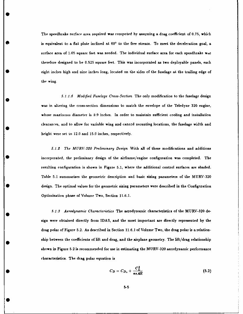
The speedbrake surface area required was computed by assuming a drag coefficient of 0.75, which
• is equivalent to a flat plate inclined at 600 to the free stream. To meet the deceleration goal, a
surface area of 1.05 square feet was needed. The individual surface area for each speedbrake wo.
therefore designed to be 0.525 square feet. This was incorporated as two deployable panels, each
* eight inches high and nine inches long, located on the sides of the fuselage at the trailing edge of
the wing.
5.1.1.6 Modified Fuselage Cross-Section The only modification to the fuselage design
was in altering the cross-section dimensions to match the envelope of the Teledyne 320 engine,
whose maximum diameter is 9.9 inches. In order to maintain sufficient cooling and installation
clearances, and to allow for variable wing and canard mounting locations, the fuselage width and
height were set to 12.0 and 15.0 inches, respectively.
5.1.2 The MURV-320 Preliminary Design With all of these modifications and additions
* incorporated, the preliminary design of the airframe/engine configuration was completed. The
resulting configuration is shown in Figure 5.1, where the additional control surfaces are shaded.
Table 5.1 summarizes the geometric description and basic sizing parameters of the MURV-320
* design. The optimal values for the geometric sizing parameters were described in the Configuration
Optimization phase of Volume Two, Section 11.6.1.
5.1.3 Aerodynamic Characteristics The aerodynamic characteristics of the MURV-320 de-
sign were obtained directly from IDAS, and the most important are directly represented by the
drag polar of Figure 5.2. As described in Section 11.6.1 of Volume Two, the drag polar is a relation-
ship between the coefficients of lift and drag, and the airplane geometry. The lift/drag relationship
shown in Figure 5.2 is recommended for use in estimating the MURV-320 aerodynamic performance
characteristics. The drag polar equation is
* CD = CDo + (5.2)reAR
5-5

Table 5.1. MURV-320 Preliminary Design Summary
OVERALL WING
TOGW 254 (lb) ALE 450(T/W)To 0.643 AR 3.50(W/S)To 11.25 (t-i) S 22.57 ft 2
Length 10.0 (ft) A 0.32Span 8.89 (ft) __5.81 (ft)
Height 2.97 (ft) Sa 1,.,/S 0.15
VERTICAL TAIL
__ALE_ 450 CANARD
AR, 1.04 AR, 2.75". 2.04 (f) VC 0.204
sT/S" 0.25 s_ 2.5 (ft 2)Travel Limit J ±300 Travel Limit ±900
VENTRAL FIN ENGINE
ALEj, 450 FSLS (uninst) 200 (Ib)
AR,, 1.04 FSLS (inst) 164 (Ib)
S,_ 1.10 (ft 2 ) SFCSLS (uninst) 1.05* Travel Limit =±300 SFCSLS (iUst) 1.2 8 ( /hrt
5-6

Il
Fiue510h UV-2 ofgrto
0-

where
CD = drag coefficient
CD. = profile drag coefficient
CL = lift coefficient
e = span efficiency factor
AR = wing aspect ratio
Other aerodynamic characteristics which relate to the degree of optimality of the configuration are
listed in Table 5.2. Recall that the objectives were to maximize CL,.., acL,.,, and CD,,.., and
minimize CD.... The values of CL, . .... etc , and CD-. were taken directly from the IDAS
results for MURV-1, with some modification for the configuration enhancements.
Maximizing the drag coefficient for approach, CD.,, was done in part by adding the speed-
brake and ventral fins. Another method for increasing CD., is to deflect the canard after touch-
down so as to produce a downward force on the nose. This increases the aerodynaimc drag and the
friction force on the nose gear simultaneously, thus enhancing the landing performance. For this
phase, this was not pursued since this method of employment is limited by the strength of the gear
strut and the hinge moment limits for the canard actuators. For the preliminary design Cp... was
estimated for the baseline MURV-320 configuration and the following relationship
• CD.pr = CDb..i- +ACD. b + ACD. ! + ACDI,
where
CDb.,, = CD from drag polar
ACDb = drag due to speedbrakes
ACD., = drag due to ventral fins
* ACDI, = drag due to landing gear
5-8
S I I

The minimum drag coefficient is basically the same as for MURV-l, though a slight increase
* can be expected for the additional drag of the ventral fins. CL.... was increased to the goal value
of 1.6 by adding trailing edge flaps. Finally, the maximum angle-of-attack, ac¢i.* , will be higher
than 24.40 due to the addition of flaps, though the extent of the increase could not be estimated
* with the tools available in the Preliminary Design Phase, thus the nomenclature 24.40+. All of
these values apply to "more is better" objectives within the limits of safe flight conditions. Given
these characteristics, the MURV-320 will be able to meet the performance constraints of takeoff and
* landing, and simultaneously be an agile baseline vehicle capable of achieving the flight conditions
necessary for a Herbst maneuver (post-stall turn). Its range and endurance capabilities are sufficient
to allow for well over 30 minutes of experimental flight time. These capabilities combine to make
* the MURV-320 baseline vehicle a high-performing baseline aircraft.
Table 5.2. Aerodynamic Characteristics of the Preliminary Design
Parameter [ Value
CL... 1.60ac*_ 24.40+
CD i, 0.025CD-11 0.344
5.1.4 Stability and Control Characteristics The stability and control characteristics were
designed according to the criteria described in Chapter IV and implemented into the configuration
as shown in Volume Two, Chapter XI. These influences resulted in a neutrally (statically) stable
* vehicle design for the maneuver condition (i.e., Cm. = 0). Ventral fins were added to assist in
executing flat turns, fuselage pointing maneuvers, vertical translation, and direct force management.
These flight modes were made feasible for the MURV-320 due to the canard/ventral fin/delta wing
* arrangement. Therefore, a wide range of supermaneuvers can be performed without adding or
modifying vehicle control surfaces. One exception is the post-stall turn, which requires a significant
side-force generation capability at high angles-of-attack and low speeds. The most effective means
• of providing the side-force at these conditions is through thrust vectoring, which was not considered
5-9

0.60
0.50
.. 0.40
oS U
0.20
* 0.10 -
0.00.0 0.2 C.4 0.6 0.8 1.0 1.2 1.4
* (Lift Coefficient (CL)
Figure 5.2. Drag Polar for Preliminary Design
for the baseline MURV design. This modification is deferred to follow-on studies.
5.2 Propulsion System
This section will outline the preliminary design for the propulsion system components of the
MURV. The propulsion system is made up of the turbojet engine, inlet, nosle, fuel system, and
electrical power system. The technical development of these systems is covered in Volume Two,
* Chapter III and only the preliminary designs will be discussed in this section. The first system
which will be covered is the engine.
5.2.1 Turbojet Engine In the conceptual design phase the The MURV was designed to have
fighter-like aircraft characteristics with a propulsion system which produced jet-like thrust. To
achieve this type of propulsion, turbojet, turbofan, pulsejet and ducted fan engines were considered.
The engine selection process was discussed in Chapter III of Volume Two and the turbojet best
5-10

suited to the needs of the MURV was determined in Section 3.1.2. The list of turbojet engines
• shown in Table 3.2 was narrowed to the two Teledyne CAE turbojet engines using the analytical
hierarchy process described in Section 3.1.2.1. The installed thrust for the two candidate engines was
calculated and used in the aircraft configuration design in Volume Two, Section 11.6 to determine
* the best engine based upon the performance analysis. These considerations and the attributes of the
engines led to the selection of the Teledyne Model 320 as the preliminary engine recommendation
for the MURV.
The Teledyne Model 320 is a low thrust, single stage centrifugal compressor turbojet designed
primarily for missile and drone use. The Model 320 has a length of 16.8 inches and a diameter of
9.9 inches. Time engine burns JP-4, JP-5, or JP-10 fuels, has a specific fuel consumption of less
* than 1.10 lbs,, /hr/lbj, and produces sea level gross thrust of 200 lbs1 . The Model 320 engine has
a substantial growth potential and may be uprated to produce more than 350 pounds thrust. The
increase in thrust will come with an increase in engine length but not diameter. This is ideally
* suited for the MURV's modular fuselage which can be easily lengthened to house and support
the longer engine. AU engine accessories are located within the engine diameter so no additional
installation clearance is needed [12]. The engine will be equipped with an alternator which will
* produce 2.0-2.5 KVA for the Model 320 [4]. An oil lubrication system will be used increase the life
of the bearings and will need to be inspected and replaced by the manufacturer after approximately
35 hours of use [12]. Engine bearing life is a function of how the engine will be used. The life is
• lengthened if the engine is run at partial power because the operating temperature is not as high.
The engine will have an exciter box driving an igniter plug to help prevent a flame out during a
post stall maneuver and to relight the engine if it does occur during a rapid turn. The exciter
* box and igniter would be turned on before the maneuver and turned off after completion of the
test. This system will help increase the reliability of the engine during abnormal flight regimes.
The exciter box could be controlled by the pilot, flight engineer or be programmed into the flight
* control system depending on the type on flight testing being performed.
5-11
SI

The cost for the engine is uncertain depending on whether the engine goes into full production
*in the future. The cost range is from $15,000 for a line production engine to $40,000 for a specially
manufactured and instrumented engine [2]. Some special modifications will have to be made to
the engine used in the MURV such as provisions for the sensors and starting system. This makes
*the lower cost figure unrealistic since it reflects an engine pulled out of a production run of 10,000
or more engines without modification. The projected lead time to procure one of the Teledyne
CAE engines is from seven to nine months after contract negotiation [4]. More specific engine
* information is listed in Appendices F and J.
5.2.1.1 Engine Starting System The Teledyne engines can be started with a cartridge
or using high pressure air impinging on the compressor to spin the engine up. The air starting
option was chosen in Volume Two, Section 3.7 because of the lighter weight of the system and
the greater control over the starting process. An access panel in the fuselage wall or cover will be
needed to connect the air hose to a quick disconnect fitting, and the ground equipment required
will be a high pressure air bottle, hose, and regulator. The required engine instrumentation will be
covered in the next section.
5.2.1.2 Engine Instrumentation As a test vehicle, the MURV has a substantial need
for data gathering capability. Engine sensors needed to support the flight testing will be installed
on the engine to measure the following quantities:
1. Engine RPM
2. Exhau- t gas temperature (EGT)
• 3. Exhaust gas pressure
4. Inlet temperature
5. Inlet pressure
5-12

0
The engine RPM, inlet temperature, and inlet pressure are standard sensors on the Teledyne
* engines, while the exhaust gas temperature and pressure sensors will have to be custom installed.
These sensors will be sampled by the data acquisition system and recorded for analysis. Engine
RPM and inlet temperature will also be used by the digital throttle controller to determine the fuel
* flow scheduling. The preliminary inlets for the MURV will be discussed in the next section.
5.2.2 Preliminary Inlet Design A preliminary inlet was designed in Volume Two, Sec-
tion 3.2.2 to meet the Model 320 airflow requirements specified by the manufacturer. This inlet was
optimized to increase the pressure recovery and the efficiency of the inlet. The inlet was shaped
with a blunt leading edge to prevent separation of flow when the capture area is less than the free
stream area required. A 45 degree extension was added to the front of the inlet which is typical
of a Mach 2 type aircraft to make the MURV appear fighter-like and to increase the capture area
of the inlet a high angles of attack. The oval cross section of the highlight was chosen because
a rounded shape has less pressure distortion than a rectangular shape. The oval was also chosen
because it has a lower profile than a circular shape. A boundary layer diverter was used to prevent
the low energy turbulent air near the fuselage from entering the inlet. The diverter also will help
prevent the inlet from being blocked from the airstream by the fuselage during negative angle of
attack flight conditions. The duct was shaped to provide uniform diffusion from the throat to the
end of the second turn in front of the engine. The height of the inlet also uniformly increased from
the throat to the exit of the second turn. A cooling air bleed interface was placed between the
second turn and the engine face. The air is split by an inner sleeve with the inside air going to
the engine compressor and the outer air going around the outside of the engine for cooling and
exiting out the boattail. The inlet will be mounted to the engine face and to the bottom structural
rails of the fuselage. The inlet is modular only in the aspect that it is easy to remove and replace
with a different duct in the event of any changes to the design. The inlet can be made out of
e-glass, s-glass, or kevlar depending upon the temperature of the engine face and the structural
5-13

loads analysed during the detailed design phase. The thick lip and throat areas can be made by
• wrapping the glass and resin around styrofoam to give the correct shape and light weight. The
inlet is shown graphically in Figure 5.3 and the key parameters are listed in Table 5.3. The nossle
considerations will be discussed next.
Table 5.3. MURV Inlet Parameters
Parameter II Model 320
Ah 19.2g2inWhi 6.56 inDhl 3.28 inA, 13.34 in2
W, 5.46 inDi 2.74 inA 2 19.63 in'
BLD 2.00 inAy 11.23 inL 38.20 in
Turn radius 13.10 inCDA 0.0004
DRAGA 1.82 lb1LB 3.69 in
• ABLD 10.60 in2
OBLD 11.010
CDEDV 0.0631DRAGBLD 2.00 lb1
17 0.918
5.2.3 Nozzle Considerations The MURV was designed with the initial mission of performing
supermaneuverability experiments. To do the Herbst maneuver, the aircraft will have to be able to
* produce some type of side forces to generate the moments required to yaw the nose around during
the post-stall condition. Thrust vectoring is one way to produce the side forces which are necessary
for this experiment. A thrust vectoring nozzle is not a part of the vehicle's baseline design because
* of the technological barriers imposed by the system. Thrust vectoring is a complex process and
is an area ideally suited as a follow on experiment for the MURV. Provisions have been made for
later efforts in this area through the fuselage's modularity. The boattail can easily be redesigned to
* accommodate a more complex nozzle and the modular rail mount can handle the additional weight
5-14

00
LL IL cI II L .
I I
I I5I 15

and loads. The only type of nozzle which the baseline MUTRV will have is a simple convergent
* nozzle which will be procured from the engine manufacturer in the required length. The length will
depend upon the final engine selection and location determined during the detailed design effort.
The next subsystem discussed is the fuel system.
5.2.4 Fuel System Design The fuel system for the vehicle is comprised of a flexible fuel
tank, throttle control system, and a fuel flow meter. The fuel tank designed in Volume Two,
Section 3.5.1 is made out of rubber and filled with open cell low density foam to reduce danger of
fire and explosion in the event of a crash. The tank will have cutouts to fit the fuselage rails for
a compact design and reduce the unused space in the fuel tank compartment. When the engine
placement and inlet design are finalized in the detail design phase, the fuel tank may have to have
a small cutout in the bottom to form fit over the inlet if a conflict exists between them. The foam
filling will displace approximately three percent of the volume of the tank and cause the tank to
have about three percent of unusable fuel due to wetting and saturation [9]. The foam will also
have the benefits of reducing fuel slosh during flight and helping the tank to maintain its shape
when depleted of fuel. The cell can be constructed of 0.020 or 0.040 inch thick material depending
on the rigidity required. The thinner and lighter material should be satisfactory for the ten gallon
tank required by the MURV. The bladder will not be affected by g loading because the tank will be
constrained on all sides by the bulkheads, floor, and ceiling which will bear the actual loads during
flight. The bladder will be compressed between the fuel and constraining surface, but this should
not be a problem [9]. The tank can be custom fit to any configuration at cost ranging from $200
for a simple design to $1000 for a more complex design. The lead time required for delivery of this
type of tank from a manufacturer, Aero Tek Laboratories, is from 2-6 weeks. The fuel tank design
is shown in Figure 5.4.
One advantage of the Teledyne engine is that the weight, complexity and electrical power
consumption are reduced because it does not require an external fuel pump. The engine has an
5-16

0
Top
Fro nt Side
Fuselage Rail • Inlet CutoutCutouts
Figure 5.4. Fuel Tank Design
* internal liquid ring pump and requires a low pressure fuel system. The fuel system is pressurized
during engine start by tapping the compressor. The small pressure loss of 0.10 percent will not
affect the performance of the engine [12]. The fuel will be routed from the fuel tank to a fuel flow
rate sensor which will be sampled by the data acquisition system and monitored on the ground. The
amount of fuel remaining on board the aircraft will be calculated from the flow rate and displayed
on the ground control console. This reading is only for back up purposes since the amount of fuel
required for the flight test plus a safety margin must be estimated and loaded before the flight.
The fuel will then go to the throttle control system which is made up of a digital controler and
a fuel flow valve. The fuel control system will be supplied with the engine by Teledyne CAE. To
command the range of idle to full thrust, the digital controller will require a 0.0-5.0 volt analog
signal from the flight control system.
0
5-17
0

5.2.5 Electrical Power system The MURV has a large requirement for electrical power be-
cause of the research missions it was designed for. There are three major electrical systems on
board the aircraft. The primary power system is the engine alternator which will produce between
2.0 and 2.5 KVA [4]. This will be augmented with the auxiliary power system made up of batteries.
• The last power system is the backup battery system which would pick up the minimum load needed
by the MURV to get the vehicle to the ground safely if the alternator should fail. Only flight critical
systems would be powered by the backup system since the mission would be aborted and the only
0 concern would be to land the vehicle safely.
The largest users of electrical power on the vehicle are the flight control and the data ac-
quisition systems. The flight control system will use power to operate the flight control computer,
electronics and electric actuators. The data acquisition system will use the power to operate the
receivers, transmitters, data gathering equipment and video system. Because of the wide variance
of power requirements for the different types of equipment available, an estimate of the number of
watt hours required for the auxiliary and backup power systems can not be determined until more
work is done and components are selected in the detailed design phase. The best type of battery
to be used can not be determined without more specific loading and cycle information, which will
• be determined in the detailed design phase. A list of battery types most likely to be used for the
MURV is located in Appendix K.
5.2.6 Propulsion System Summary Tne integration of the engine and related subcompo-
nents have been discussed and the preliminary designs outlined. The Teledyne Model 320 engine
characteristics were listed and the matching optimized inlet was described. The fuel system was
* presented with the preliminary fuel tank design. The electrical power system was outlined with
most of the design left to the detailed phase of the project because of the dependence upon sub-
component selection and power needs.
5-18

5.3 Flzght Control System Design
This section presents the conceptual design of the control system as applied to the MURV-320
configuration. The development identified mission requirements and used them to specify sensor
and control surface requirements. Control system architecture was developed in accordance with
design objectives derived from the objective hierarchy.
MURV-320 provides many possibilities for advanced control concepts. The main design fea-
ture is the use of a forebody canard which eliminates the requirement for a horizontal tail and
provides a higher degree of maneuverability. This will enhance MURV mission flexibility achieved
through flight control system variations. The design objectives of the MURV flight control system
were to provide:
1. Provide mission flexibility
2. Provide adequate control for defined missions
3. Provide adequate reliability
4. Minimize constraints on functional interfaces
5. Minimize on-board weight
6. Minimize on-board volume
7. Be affordable
A digital flight control system is required to make the MURV capable of a performing a range
of flight tests. A benefit of a digital flight control system is that it easily provides a range of feasible
aerodynamic designs. The aerodynamic characteristics, e.g. marginal stability, of MURV-320 make
the MURV suitable for advanced control methods specified earlier. For the conceptual design of
the control system our goal was to:
1. Select specific mission scenarios
* 2. Develop control system functional requirements
3. Identify/analyze feasible designs
4. Develop interface requirements
5-19

5.3.1 Mission Scenarios Of the types of experiments considered in Volume One, Chapter
* 4, supernianeuverability was selected and used to identify MURV flight modes. These flight modes
are representative of advanced control concepts which could be implemented by AFIT researchers.
The MURV will be capable of the following flight phases and maneuver flight modes.
* Conventional flight phases
- Take-off
- Climb
- Cruise
- Standard turn
- Landing
* Maneuver flight modes
• - Pitch Pointing
- Vertical Translation
- Direct Lift
- Yaw Pointing
- Lateral Translation
- Direct Sideforce
5.3.2 Measurement and Discrete Data Requirements For each of the flight modes identified
* previously, measurement and command requirements were defined. The following list includes the
entire suite of sensor data and remote cockpit commands required to support the control system.
* Onboard data
* - Pitch attitude
- Pitch,roll and yaw rates
- Normal and lateral acceleration
- Dynamic pressure
- Static pressure
- Angle-of-attack
- Angle-of-sideslip
- RH and LH Canard Position
- RH and LH Aileron Position
- RH and LH Elevator Position
5-20

- RH and LH Ventral Fin Position
- RH and LH Trailing Edge Flap Position
- RH and LH Spoiler Position
- Rudder Position
- Engine RPM
- Fuel flow rate
9 Remote cockpit
- Stick pitch and roll forces/positions
- Stick rudder force/position
- Throttle position
Flight critical data, data required for the safe operation of the MURV, must be identified.
Parameters identified as such should have backup sensors which would be available to both the
primary and backup control loops. In addition, the remote cockpit will provide the following
discrete information to the flight control system.
1. Flight mode selection - implement particular control law
2. Built-in-test - conduct system diagnostic test
3. Engage back up control system - pilot initiated switch
4. Preplanned flight maneuver - execute preprogrammed flight plan
In addition to the aforementioned data, subsystem status acquired on-board should be pro-
cessed on-board and transmitted with the proportional data to provide the pilot with system status.
Some component failures will result in automatic transfer to the backup control system while others
will switch to redundant components. In all, twenty six proportional parameters and an undefined
number of discrete commands are required for the flight control system.
5..2.1 Data Rates The MURV will be statically unstable during some mission phases
making the digital flight control system necessary for stable controlled flight. The sampling rates
5-21

of the desired measurements is a critical design factor in this application. Based on comparable
• flight systems, data sampling frequencies on the order of 220 Hz with command rates on the order
of 40 - 55 Hz can be expected.
5.3.2.2 Measurement Accuracy and Error The effects of sensor accuracy and error
requires the characterization of the sensor noise and analog-to-digital conversion errors. These
models will be used with the candidate control laws to generate performance data for comparison
to design specifications. The results can lead to tighter sensor specifications or alternative control
algorithms. See Chapter 6, Section 6.4 for further information
5.3.2.3 Interface Considerations Each particular flight mode has a set of required
state information needed for implementation. Future experiment designs may require the addition
of some states. The goal in the preliminary design was to identify foreseeable requirements and
include them in the baseline. Discrete data requirements will vary. Addition of functions, such
as, air brakes, two position forebody strakes and a parachute introduce requirements in both the
telemetry system and the remote cockpit.
5.3.3 Control Surface Requirements Normally, control about the lateral axis is achieved by
means of the horizontal tail. MURV-320, the proposed vehicle configuration, has no horizontal tail.
The plain trailing edge will be split into a minimum of two sections combining the functions of the
ailerons and elevators. In the following discussion, the split trailing edge will be referred to as these
functional elements. Preliminary control surfaces requirements are:
* RH and LH Canards
* RH and LH Ailerons
e RH and LH Elevators
* RH and LH Ventral Fins
* RH and LH Trailing Edge Flaps
* RH and LH Spoilers
• * Rudder
5-22
0 . . . ... ... .......

Table 5.4. HiMat Actuator Parameters
Control Surface Rate (deg/s) Maximum Deflections (degs)
Elevators 76.6 +28 to -21
Elevons 87.2 +27.5 to -20
Rudder 65.6 +10 to -10Ailerons 86.8 +20 to -20Canard 87.3 +18 to -20
If the detailed design of the MURV results with these conventional surfaces, some provision
• should be made for the potential failure of a flight critical control surfaces. One level of redundancy
will be provided for each flight critical surface. The following control surfaces may be required to
achieve performance requirements.
1. Leading edge flaps - provides increased wing lift
2. Dorsal fins - provides directional stability at medium angles of attack
* •3. Forebody strakes - provides increased yaw effectiveness at high angles of attack
Once the control surfaces are sized and the flight envelopes defined the actuators can be specified
in terms of:
1. Maximum hinge moments
2. Maximum surface deflections
3. Maximum surface rates
Table 5.3.3 contains the rate and range of the hydraulic powered control surfaces employed
* on NASA's HiMat remotely piloted research vehicle [55]. The range of these parameters provide
some insight for future design efforts.
The selection of the actuation system was deferred to detailed design. An all-electric actua-
* tion system will improve the modularity of the MURV and would reduce total flight control system
5-23
Si

weight compared to a hydraulic system. The actuator system represents 60 % of the total flight
* control system weight in full scale aircraft [63]. Due to the scale size of thee MURV this percentage
could be higher. Actuators also occupy volume and consume power, two other constrained design
parameters. The volume of actuators will be considered in the final scaling of the MURV config-
ie urations. The power distribution unit must provide adequate and reliable power for the actuator
system. As a flight critical element the power distribution unit will have a backup battery to
provide a power level sufficient for safe operation.
5.3.4 Flight Control System Architecture Feasible flight control system designs were devel-
oped and evaluated based on the following design objectives:
1. Minimize on-board weight
2. Minimise on-board volume
3. Maximize flexibility of flight control system
4. Maximize reliability of flight control system
5. Make flight control system affordable
5.3.4.1 Requirements for the Flight Control System One of the most critical interfaces
of the flight control system is the data acquisition system. These elements will be compatible and
provide suitable performance specified in terms of response times, data word length, addressable
memory and method of processing, paralel versus serial.
The flight control system will perform the following tasks:
* 1. Process the input data via resident control laws
2. Provide a command vector for telemetry uplink
3. Provide servo-actuator control
4. Provide failure detection and isolation of flight critical components
5. Provide sensor data processing
5-24

6. Provide uplink and downlink data processing
The central computer of the flight control system is a flight critical component. Therefore,
there will some provision for a failed central computer. The selected flight control system concept
for the MURV is composed of three flight computers: a ground based central computer and on-
board primary and backup flight computers. Figures 5.3.4.1, 5.3.4.1, and 5.3.4.1 are preliminary
breakdowns of the functional elements of the MURV flight control programs.
SCENTRAL
0r
CFLIGHI
u~~ws EXECUTIVE]TS
KE MOTEDECOE
r~~o~ss j PMossRCOES
0R
CONWERSIOM T
Figure 5.5. Central Flight Control Program
5-25
0

FUL I -
PROCES~tC INTT AT
F F948A 1RTE RRUPT OROrti
* ~NTL IN FPoRINLESE U1
L TELMETR
P~OCE~IPGPROCESSIN
0P ;(
Figure 5.6. Primary Flight Control Program
5-26

FMEHTPiRO<;PAkd
<XOONTP(CL EECUTIET't LAWS
F~O~AM KIT PRINPUT AND PcA
IMMAL,,ATU PROCSS ING ,C
E -SO 1TL EMETRT KPYUAO
I.TA LIPLINK FLIGHT CON toO
PROCESSING h2DES
Figure 5.7. Backup Flight Control Program
5-27

Later design efforts will define the computer requirements such as:
1. Clock speed
2. Read only memory capacity
3. Random access memory
4. Word length
* 5. Data interface bus
While no detailed requirements can be analytically developed at this point of the design, we
recommend the 32-bit class of microprocessors for the MURV system. The use of 32-bit processors
is proliferating as an affordable alternative for high performance control applications [66]. The
growth capability of the MURV should be enhanced by the specification of a 32-bit microprocessor.
While it is unlikely the full potential of the 32-bit machine will be required initially, it will provide
flexibility for the control system designers.
5.3.4.2 Control Law Development Since control law development and test is one of
• the purposes for the MURV system, requirements in terms of control methods were not defined.
The MURV will employ advanced control concepts relating to je; fighter performance. Performance
requirements are available in the "Flying Qualities of Piloted Airplanes", MIL-F-8785C [26], and
* "RPV Flying Qualities Design Criteria" [80].
5.3.4.3 Functional Allocation Elements of the flight control system which must reside
on-board are:
1. Sensors
2. Signal conditioners
3. Control surface actuators
• 4. Servo-motor controllers
5. Onboard flight controller
The selected architecture, Figure 5.3.4.3, locates the central flight computer on the ground
* and a primary and backup computer on-board the vehicle. The central computer program residing
5-28

in the ground computer will contain the MURV flight control laws and preplanned flight maneuvers.
* The preplanned maneuvers are required to provide experimental repeatability for data acquisition.
BACKUP ,:DMt PLITEPB RACKUP uONTROL MUDES. T
S SO': P- .- ' D.ATA PPI'OCEE!ING A
E -TELEMETRY LJF'LIrfi:. .C
P - SEN S I:R ['; A PR-:'DE SS5IN: US - .:R" I:.I' v AT' TAI'S*e0'I ST-- I,,- I 1 T
TELEMETF!fY TELEMETRY IDIJ .,VN LIN K t Ip N K _
PR I MAR",( COMPUTER
Sn O- b :u rdGrourd Bu:sed
TEL EMI ETF"r -ELEM ETRY'iREC 'EIVER TRANS
CENTRAL COMPUTER
D.IA REMOTEFRi)E'-.JR COCK PIT PREPLANNED ENCODER
FLT PLANS
Figure 5.8. Digital Flight Control System #2
* The primary flight compiter tasks include sensor processing, component health and status
monitoring, telemetry data processing and servo-control. Sensor processing includes signal filtering,
smoothing and redundant sensor data comparison. Health and status will be provided for all
• elements of the flight control system. Software should be developed respond to flight critical
5-29

S
component failures located on-board the MURV. Data management for the telemetry uplink and
*s downlink should be provided. The controller-actuator interface, not yet defined, should provide
closed loop servo control.
The backup flight control computer performs functions similar to the primary. The exceptions
are the system status and telemetry processing requirements. The backup controller should provide
both open loop control and preplanned flight modes for independent operation.
* 5.3.5 FCS Design Summary This section presented the conceptual design for the MURV
flight control system. Using the design objective and the supermaneuverability flight modes, re-
quirements were developed for sensors, control surfaces and the functional allocation of the control
* system. The elements of the flight control system which are important for the success of the MURV
concept were emphasized. These include actuator requirements, primary control loop cycle time
and on-board weight, volume and power requirements. At this stage of the actuator and cycle
times were not were not specified. They are addressed in Volume One, Chapter 6, Section 6.4
which provides a summary of the detailed design efforts to be conducted.
5.4 Launch/Recovery System
The launch/recovery system of the MURV ended up as two separate designs: one a detachable
dolly for the launch, and the other an onboard set of rear skids and front wheel for recovery. The
* primary reason for the separate designs was the high weighting that was given to the estimated
weight of onboard Launch/Recovery System equipment in the selection process (see Section 5.4.5
of Volume Two for additional details). The outcome of this weighting factor was the removal of any
* equipment needed for the launch from the MURV itself and placing it on the dolly instead. The
following sections are descriptions for each of these two designs including the major components
and their features.
5-30

5.4.1 Launch System The launch system is based on a typical tricycle undercarriage ar-
rangement with the two main wheels located behind the MURV's c.g. and a single steerable nose
wheel located in front. Figure 5.9 shows the overall launch system and the following is a description
of the major components identified in this figure.
a. I
0 5. - OCWr
1. Sa AM*
0. s m
Figure 5.9. MURV Launch System
1. The rear axle of the doily is a single piece made up of either a solid core composite tubular
design or tubular steel design. The ends are designed to attach the rear wheels with no
complex linkages, bearings, or brakes. This type of design is extremely simple, however, it
still has very high strength and shock absorption properties.
5-31
0#

2. The rear wheels are essentially all-terrain bicycle wheels with built-in bearings such as those
* used in motocross bikes. A possible modification would be to replace the inner tube tire
with a solid rubber tire to eliminate any posssibility of a flat tire during the takeoff roll.
Using standard mototcross bike wheels with solid core tires would simplify the design without
* sacrificing any strength or reliability.
3. The rear axle is attached to the structure of the dolly with a set of bungee shock cords
to dampen the loads experienced in the acceleration down the runway. These shock cords
would be wound around the attachment points between the axle and the frame of the dolly.
This simple, but effective shock absorption method has been revived for use in modern ultra-
light and light aircraft design. The figure in Section 5.5.2.1 of Volume Two shows a typical
attachment using this type of design.
4. The structure of the dolly is based on a simple truss design using either composite or aluminum
tubular materials. Gussets for strength will be used where needed. By using a truss design
the weight of the structure can be minimised without impacting the strength of the structure.
5. The cradle of the dolly will conform to the contour of the bottom of the MURV's fuselage
with modifications wherever necessary to accomodate the wing, strakes, inlet, or any other
protruding member. This should allow the MURV to be reconfigured with only a slight if any
modification to the dolly.
* 6. A screen is incorporated in to the cradle to protect the inlet of the MURV's internal turbojet
engine from foreign object damage (FOD). By using a material such as the metal mesh from
a house screen door the probability of FOD can be significantly reduced.
* 7. The front nose gear is a simple telescopic strut with the addition of a steering linkage at
the top of the strut. The strut incorporates a "positive trail" (see Section 5.5.3.2 of Volume
Two) to allow proper castering of the nose wheel. The wheels and need not be any more
* complex than those of the rear wheels and as such a small bicycle wheel would suffice. The
5-32
0"

bearings might require a small improvement over those used in the rear wheels because of the
* requirement for steering. The use of a tubed tire is included because the increase in the grip
of this type of tire increases the steering authority for the nose wheel during the low speed
turning.
8. The steering linkage from the nose gear is connected to an actuator situated at the base of the
dolly structure. This actuator, in turn, is connected to a receiver which will receive command
inputs from the operator and thereby command the steering of the dolly. The inputs to the
steering of the dolly are linked electronically with the inputs to the rudder. This linkage
is critical for the takeoff because the operator uses inputs to the dolly nose wheel steering
for low speed steering, but needs to smoothly transition to inputs to the rudder as airspeed
increases. This is due to the fact that the rudder has very little control authority at low
airspeeds whereas the nose wheel has its highest control authority. As the airspeed increases
this control authority reverses between the two. Therefore it is essential that the operator
0 should not have to switch from one to the other during the takeoff.
9. Located at the rear of the dolly, the canister for the drogue chute has a spring loaded plunger
which deploys the chute into the airstream where it would rapidly inflate and decelerate the
dolly. A shock cord attached to the drogue lines dampens the shock of the parachute's initial
inflation. This design was preferred over the use of brakes because of its simplicity, weight
savings and deceleration capability.
10. (Not shown in Figure 5.9). In the event that the combined weight of the MURV and its
dolly are so great that the thrust provided by the MURV's internal engine can not accelerate
the MURV to takeoff velocity within the constraint of the runway at the Jefferson Proving
Ground, an additional propulsive force could be added to the dolly. This additional force
could be supplied by many means such as a small electric motor, a small gasoline engine, or
a flywheel. Currently, the combined weight of the MURV and its dolly does not appear to
5-33

pose a problem.
5.4.2 Recovery System The recovery system for the MURV uses the same general tricycle
type arrangement as the launch system, however, the rear landing gear is made up of skids rather
than wheels. A major difference with the launch system is that the rear skids and nose wheel for
the recovery system are pretracted (i.e. they are stored in the fuselage prior to landing). This
feature was due to a constraint from the selection process found in Section 5.1.5 of Volume Two.
This constraint required that the MURV be capable of having a clean aerodynamic surface so that
it could perform supermanueverability tests. Figure 5.10 shows the overall recovery system and the
following is a description of the various components identified in this figure.
1. The rear main strut is based on the properties of a cantilevered spring (see Section 5.5.2.1,
Volume Two for details). By using a composite construction cantilevered spring a very strong,
light weight strut with a considerable weight savings over a comparable steel or aluminum
strut is realized.
2. The skids are attached to the struts by way of a restricted motion joint. The restricted motion
joint is used because of the small amount of pivoting required by the skids. Some method
to ensure the skids remain oriented, parallel to the centerline of the fuselage (possibly cables
running between the two skids on the front and back of the skid as shown in the figure) must
be included.
3. The best material for the bottom of the skid is hard rubber because of its high coefficient
of friction. However, after the MURV has landed, this ruaber material will have received a
certain amount of abrasive damage. To alleviate this problem the skid design incorporates a
rubber boot that can be easily replaced after the landing so as not to impact the aerodynamics
of the MURV.
5-34

<... E ii ----
/ / 4 G
tI
0 S
* Figure 5.10. MURV Recovery System
4. The decision on the type of shock absorber within the front strut was not deemed necessary
at this point (see Section 5.5.3.2, Volume Two). However, a strut incorporating a "positive
tradl (explained in the same section referred to above) was required. The nose gear strut
depicted in Figure 5.10 is a likely candidate for the MURV.
5. The nose wheel for the recovery system has many of the design properties of the nose wheel for
the launch system discussed previously. However, because of the higher loads due to landing,
a wider tube tire with better shock absorption characteristics is preferred.
5-35

6. Located at the top of the nose strut is the steering linkage. This linkage is connected to an
0 on board actuator that will be given inputs by the flight control computer that match the
inputs to the rudder.
7. The nose gear door for the MURV is hinged along the side of the nose wheel well with the
addition of a spring within the hinge to restrict the amount the door can open and to prohibit
the door from fluttering in the airstream.
8. Because of the potential for FOD in the inlet for the internal turbojet, two precautionary
devices are envisioned. The first is a small shield (similar to an automobile mud guard)
located just behind the front nose wheel. The second device is an inlet cover (made up of a
metal mesh similar to a house screen door) that deploys just prior to landing.
9. To allow the operator to have positive indications for the landing gear for both the stowed
position and the down and locked position, sensors are needed to transmit this data via the
telemetry link.
5.5 Data Acquisition System Design
* The primary objective of the MURV data acquisition system was to provide the necessary
data to allow command and control of the MURV and to provide for experimental needs. It was
also necessary to maintain the flexibility to perform various experiments on a number of different
* aircraft configurations. This section outlines the design developed to accomplish that objective,
and cites the functional requirements for the data system. The design and requirement specification
was done based on the following subsystem objectives:
1. Maximise data accuracy
2. Maxinise design flexibility by providing for:
* (a) Subsystem modularity
5-36

(b) Expansion capability
3. Minimize onboard equipment weight and volume
4. Maximize system reliability
5. Minimize complexity and cost
6. Maximize market availability of components
The analyses that led to the following design can be found in Volume Two, Chapter VI.
5.5.1 System Description A functional diagram of the onboard data acquisition system,
which was derived from Reference [361, is shown in Figure 5.11. The system consists of the aircraft
sensors, signal conditioning circuits, multiplexer, analog-to-digital converter for interface with the
data and control bus, PCM (Pulse Code Modulation) encoder and transmitter. Also included is a
system clock for data synchronization, interfaces for engine and control surface actuator control,
and the receiver for the telemetry command uplink. It can be seen that in this configuration the
video camera requires a separate transmitter. All of the functions shown here are controlled by a
microprocessor, with the use of a programmable data bus.
Figure 5.11 is a candidate solution for the MURV data acquisition system and may not rep-
resent the final design architecture. Each telemetry system manufacturer will have a different
implementation of the same functions. The onboard data system should be purchased as a sys-
tent, with modular components and expansion capabilities, in an effort to reduce the component
integration requirements. The optimum solution, based on system performance alone, would pro-
vide software and bus control of all of the functions shown. However, the consideration of other
objectives, such as cost, equipment weight and volume, may justify the selection of a system that
does not provide processor control of all the functions shown in Figure 5.11. To provide the flexi-
bility required for the MURV, signal conditioning, multiplexing, A/D conversion and PCM frame
• construction, as a minimum, must be software controlled.
5-37
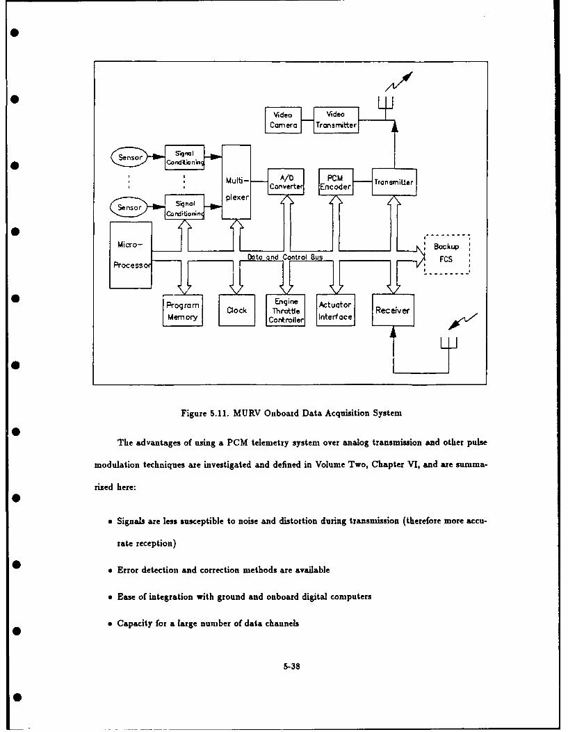
4 Vide o V Irside
TS .
plexer Coer er
Micro- I Backup
Figure 5.11. MURV Onboard Data Acquisition System
The advantages of using a PCM telemetry system over analog transmission and other pulse
modulation techniques are investigated and defined in Volume Two, Chapter VI, and are summa-
rized here:
* Signals are less susceptible to noise and distortion during transmission (therefore more accu-
rate reception)
• * Error detection and correction methods are available
* Ease of integration with ground and onboard digital computers
* Capacity for a large number of data channels
5-38

" Ability to increase data accuracy by increasing digital word length
e Flexibility provided by supercommutation and subcommutation
* Widely used in aircraft testing
* The flexibility and advantages of a software-controlled data acquisition system are evidenced
by the fact that practically every element of the telemetry system can be tested, controlled and
modified in software. This reduces the need for time-consuming, specialized changes in hardware.
• Also, the programmable data and control bus allows addition of modularized components to the
data system, with a minimum of system changes. The advantages of the microprocessor-controlled
system are summarized below:
" Software alteration of sampling rates, parameter resolution, signal conditioning requirements,
and PCM frame construction
* Comprehensive built-in-test capability
" Greater system growth potential
" Increased system modularity
5.5.2 Data Collection The data to be collected onboard the MURV is listed in Table 5.5.
As noted in Volume Two, Section 6.2.1, the ranges listed here are preliminary and must be verified
and refined as the design progresses.
There are a number of health indicators required by the pilot and/or flight control system in
order to recognize potential problems, or verify the actuation of a discrete command. An initial
• estimate of these requirements as shown in Table 5.6. These status indicators may be displayed
on a cockpit instrument, such as a battery voltage gauge, or simply actuate a warning light. In
the first case, the parameters must be measured and sent down as a proportional reading. In the
• latter, it would be necessary only to transmit a discrete, or two-position, signal.
5-39

Table 5.5. Proportional Onboard Measurements
SrParameter f Units Range_ _ Minimum Maximum
Normal Acceleration G -3 9Longitudinal Acceleration G -3 3Lateral Acceleration G -3 3Angle of Attack Degrees -30 90Angle of Sideslip Degrees -45 45Pitch Angle Degrees -90 90Roll Angle Degrees -180 180Pitch Rate Deg/sec -100 100Roll Rate Deg/sec -720 720Yaw Rate Deg/sec -30 30Static Pressure psia 0 15Total Pressure psia 0 35Air Temperature Deg C -55 85Magnetic Heading Degrees 0 360Engine RPM RPM 20,000 72,000Engine Fuel Flow Rate lbs/hr 0 150
0 Engine Inlet Temperature Deg -55 85Engine Exhaust Temperature Deg R 510 2100Engine Inlet Pressure psia * *Engine Exhaust Pressure psia * *Video Camera Picture N/A N/A N/AControl Surface Positions and Hi ge MomentsLeft/Right Canard Positions Degrees * *Left/Right Aileron Positions Degrees * *Left/Right Flap Positions 2-3 positions N/A N/ALeft/Right Spoiler Postions Degrees * *
Left/Right Ventral Fin Positions Degrees * *
Rudder Position Degrees * *• *To be determined in a follow-on study.
5.5.2.1 Air Data Measurement Methods for measuring air data (total and static pres-
sure, angle of attack and angle of sideslip) in a highly maneuverable environment on an aircraft
that is subject to configuration changes is investigated in Volume Two, Section 6.2.3. The rec-
ommended solution is an integrated differential pressure probe, with error compensation, mounted
on the fuselage nose boom. The error compensation can be provided by the digital transducers
described in Reference [35], or in the onboard data processing module.
5.5.2.2 Flight Critical Parameters Flight critical parameters are the minimum data
* requirements necessary for the control of the MURV. The measurement and transmittal of these
5-40

Table 5.6. Onboard Health Indicators
• Health Indicator Sensing Method
Telemetry uplink status Carrier-operated relay in airborne receiverTelemetry downlink status Carrier-operated relay in ground receiverVideo camera status Carrier-operated relay in ground TV receiverGenerator/Alternator status Acceptable voltage levelBattery status Acceptable voltage level
* Backup FCS engaged indication Main computer signalLanding gear position (up/down) Pressure switchLanding gear locked/unlocked Pressure switch
parameters are essential to the operation of the MURV, therefore provisions must be made to ensure
reliable system operation. All flight critical transducers should be double or triple redundant, with
a voting or averaging concept to resolve the multiple sensor inputs. This decision logic would
be accomplished by the onboard processing system in order to limit the number of transmitted
data channels and because this critical data is also required by the onboard flight control system.
Additionally, sensor integrity checks, such as the monitoring of signal voltage levels, could aid in
the voting logic or be used to reprogram the flight control system to neglect that parameter, as
needed.
5.5.3 Signal Conditioning Onboard signal conditioning will be required for the transducer
* outputs and commands transmitted from the ground in a number of areas, including amplification,
signal conversion, and filtering. Specific signal conditioning requirements must be defined based
on the selection of transducers and the telemetry system components. General requirements are
• defined below:
" Low pass filtering to prevent aliasing must be accomplished for all analog signals prior to
sampling.
" Signal amplification (e.g., voltage, power) will be required for low output transducers.
* Signal conversion may be required for compatibility with other system components (e.g.,
* conversion of an AC analog signal to a DC analog signal with range 0-5 volts).
5-41

" Analog transducer signals require analog-to-digital conversion before transmission on data
* bus or signal carrier.
* Digital control commands may require conversion to analog signals in order to execute the
command.
The signal conditioning hardware and software design should be modularized to allow modification
for system changes.
5.5.4 Telemetry The selection of a PCM/FM telemetry system was made based on the
factors outlined above. The telemetry system, which encompasses the functions of multiplexing,
PCM encoding, and transmission, is a critical element of the MURV data acquisition system. The
requirements defined for the telemetry system are contained in this section.
5.5.4.1 PCM Encoding PCM encoding involves converting analog or digital signals to
* a binary code that is compatible with the transmission and receiving systems. In some telemetry
systems, the particular PCM code (e.g., non-return-to-zero, biphase) is selectable in software [35].
This would be desirable in the MURV system. The selection of resolution for proportional data
should also require only a software change, and be a minimum of 12 bits per word.
5.5.4.2 Transmitters and Receivers We recommend that the PCM downlink, PCM
command uplink, and video downlink be modulated on separate transmission frequencies. The
appropriate frequency band for aircraft telemetry systems is L-band (1435-1540 MHz) [97]. The
telemetry transmitters and receivers should be capable of being tuned to all frequencies in the
L-band range.
It is possibile to multiplex the PCM and video camera signals for sinultaneous transmission.
A survey of telemetry equipment suppliers would be required to ensure that such an arrangement
5-42

would provide sufficient bandwidth for the PCM data. Since this arrangement would require only
• one onboard transmitter, the potential exists for onboard weight, volume and power savings.
A discussion with a telemetry equipment manufacturer II01) revealed that PCM systems with
the capability for bit rates of I MHz are "normal." Based on the preliminary data rate calculation
0 done in Volume Two, Section 6.3.5, 1 MHz would provide more than five times the required speed.
Transmission bandwidth allocation is specified as narrow, medium or wideband [97]. A nar-
rowband channel of 1 MHz should be sufficient for both PCM links. The video transmission will
require a mediumband or wideband allocation (typically requires 3-6 MHz bandwidth).
Telemetry transmitters use either frequency modulation or phase modulation. FM will be
used to modulate the MURV carrier signals due to its superior signal-to-noise ratio performance
and more efficient bandwith usage [96:3.0-2-3.0-51.
5.5.5 Data Processing and Recording The data acquisition system ground functions are
* depicted in Figure 5.12 and include receiving in-flight data, data processing, data recording, real-
time display, and transmitting command and control information. This figure also shows the general
interfaces between the data acquisition system and the flight control system.
The data processing system may be a separate computer or an allocated function in the main
ground computer that includes the flight control system. The functions that may be performed by
the data processing system include:
e Calibration (conversion to engineering units)
e Calculation of derived parameters, such as aerodynamic coefficients
5 * Data compression
* Signal conversion of inputs to the remote cockpit
* Processing data for real-time display
5-43

0
*Data
W Control TransmitterRec eiv er Pro ce ssi ng System
Rec eiv er Co ckpit
• _ Real-time
Display
* Figure 5.12. Schematic of the MiRV Data Acquisition Ground Station
9 Data manipulation for recording
* Data storage of calculated values for quick-look analysis
Digital data recording is necessary for preserving the flight data for post-test analysis and
permanent data storage. The most promising methods for digital recording are on digital magnetic
* tape or computer disk. The advantages and disadvantages of each are discussed in Volume Two,
Chapter VI. Individual parameters may be recorded in a serial bit stream or in parallel channels
after, or prior to, calibration and/or data compression. These functions will be automatically
• controlled and may be easily changed through software at the ground station.
Real-time analysis involves display of flight data in a form that can be used for immediate
interpretation. This may be required for safety-of-flight reasons, and can ensure the most efficient
use of flight time for any test. The methods for display, such as a CRT screen, analog or digital in-
5-44

dicators, or strip chart recorders, can also be used for post-test analysis at the test site immediately
• following the test.
5.5.6 Data Acquisition System Design Summary The subsystem objectives of the MURV
data acquisition system were used to specify the preliminary design for both the onboard data
acquisition equipment and the ground station equipment. As outlined in this section, data accuracy,
modularity, design flexibility and system reliability had a significant impact on every functional
component of the data system. The other objectives which were considered, but did not have
as large an effect on the design at this stage, were minimization of equipment weight, volume,
complexity, cost and maximization of market availability. These factors will more greatly influence
the design as the detail increases and actual component selection takes place.
5.6 Structural Design
Introduction This section will describe the structural design of the MURV, in-
cluding the fuselage, wing, empennage, and how the other subsystems and components attach to
the fuselage. A description of how this design was developed is in the Structural Design/Modularity
Chapter in Volume Two.
5.6.1 Fuselage Structure The fuselage will be made up of three sections, the nosecone, main
fuselage, and boattail (Figure 5.13).
5.6.1.1 Main Fuselage The main fuselage will have a constant cross section throughout
its length. This cross section will be a rectangle with rounded corners. A cross-sectional view of
the fuselage structure is shown in Figure 5.14.
Fuselage Rails The "rails" are the main structural elements of the main fuselage.
They will extend the full length of the main fuselage. They will be square aluminum box-beam
5-45

Main fuselage
• Nosecone Boattai
* Figure 5.13. Side View of Fuselage
Cover
S id ew aIlI
•=ff Rail
* Figure 5.14. Fuselage Cross-Section
5-46

tubes, approximately 1 1/2 inches on a side with 3/16 inch thick walls. They will have smooth-bore
* holes every two to four inches along the sides to which the sidewalls will attach, and tapped holes
every one to two inches on the other three sides. The holes will be about 1/4 inch in diameter. It
is important to note that all dimensions in this section are only first estimates; further analysis is
* required to establish the actual dimensions.
All of the load-carrying structures (the wing, empennage, landing gear, etc.) will attach to
the rails, as will all the components inside the fuselage (such as the engine and avionics computers).
They will attach with bolts, which will thread into the tapped holes in the rails. The constant cross
section, along with the holes along the length of the rails, will allow the items attached to the rails
to be shifted fore and aft with a minimum of effort. Most of the internal equipment will attach to
0 frames, which will mount to the rails. The engine will be installed this way, and an installation
concept is shown in Figure 5.15. The size of the fuselage is based on the engine diameter. There will
be an approximate one inch gap between the planes formed by the outer surfaces of the rails and
0 the engine at its widest point. Thus, for the Teledyne 320 engine which has a 9.9 inch maximum
diameter (see Section 5.2.1), the fuselage will be approximately 12 inches wide. The height of the
fuselage, without covers, will also be about 12 inches.
The rail design allows for simple addition, removal, or replacement of fuselage sections by
having joints in the rails at various locations along the fuselage. The baseline MURV will not have
any rail joints. A joint would consist of a square inner sleeve with tapped holes, which would fit
inside the ends of two rails butted together. The sleeves would be made of aluminum, or perhaps a
stronger material if the loads require it. The last few holes in the rails would be smooth-bored and
would match up with the holes in the sleeve. Each rail would then be bolted to the sleeve, forming
a butt joint (Figure 5.16).
If a piece of equipment needed to be attached to the rails at a point where there was a joint,
the bolt which would normally thread into a tapped hole in the rail would instead go through the
5-47

Engine
Mountingframe
Figure 5.15. Cross-Section View of Engine Mounting in Fuselage
5-48

Sleeve
00F
00
Figure 5.16. Fuselage Rail Joint Design
5-49

smooth-bored hole in the rail and thread into the tapped hole in the sleeve. Tightening the bolt
would then secure the equipment to the rail and tighten the rail joint simultaneously.
More joints can be added by cutting the rails between two sets of holes and boring out the
holes in the rails on either side of the cut. A joining sleeve can then be inserted into the ends of
the rails and fastened in place with bolts as shown in Figure 5.16.
Fuselage Sidewalls The sidewalls will be made of 1/16 to 1/8 inch composite,
either fiberglass or a stronger composite such as KEVLAR. Which material is to be used will
depend on further loads analysis. The sidewalls will attach to the rails with flush, quick-release
fasteners placed every two to four inches along the length of the main fuselage. The fasteners will
fit through holes in the sidewalls and into the holes in the rails. A brand of fastener which could be
used is Camloc (manufactured by Rexnord Aerospace Products [82]). Using composite material
for the sidewalls will require that they be made with the holes "built-in", to maximize strength.
The sidewalls would also have joints. A sidewall joint would consist of two sidewalls butting up
to each other, with a flat sheet of sidewall material covering the joint on the inside of the fuselage.
The flat sheet would be approximately four to six inches wide, and would fill the area between
the fuselage rails in the vertical direction. The sidewalls would be attached to the joining sheet
by removable flush fasteners so that the the exterior of the joint would be smooth. The baseline
MURV will have a single pair of sidewall joints (one on either side of the fuselage), immediately
forward of the front end of the fuel tank. A typical sidewall joint is illustrated in Figure 5.17.
Fuselage Covers Top and bottom fuselage covers will be mounted on the fuselage
in the areas where no aerodynamic surfaces will be attached. The skin will be made of composite,
and the supports for the rounded portions of the covers will be made of a lightweight wood, such
as spruce. The skin will be between 1/16 and 1/8 inch thick, and the complete covers will be ap-
proximately 1 1/2 inches tall. This will make the height of the fuselage, with covers, approximately
5-50
0

0
0
Figure 5.17. Sidewall Joint Design

15 inches.
The covers will attach to the rails with standard machine screws, which will go through holes
in the wood corner supports and thread into the holes in the rails. The holes in the covers will be
counterbored so that the screw heads will not protrude into the airstream. The holes will then be
covered with tape to reduce drag.
A typical cover would be about one foot long. The length, number, and placement of the covers
will be designed around the particular wing/empennage configuration and internal arrangement.
There will be no structural "joints" between adjacent covers, they will simply butt up to one
another.
* Bulkheads and Stiffeners Bulkheads will be mounted where necessary at various
points along the length of the fuselage to give it strength in the vertical and lateral directions. These
bulkheads, attached to the rails, will be movable to allow for changing internal arrangements. The
I •baseline MURV will have two bulkheads, one at either end of the fuel tank. The MURV can also
have stiffeners mounted to the rails, for added strength. Further structural analysis needs to be
performed before it is known whether the baseline MURV will need stiffeners.
5.6.1.2 Nosecone Design The nosecone will start from a pointed or rounded tip, and
gradually increase in diameter until its surfaces match up with the outer surfaces of the main
fuselage (with covers attached). It will be attached structurally to the fuselage rails, and will be
hinged so that it can pivot horisontally as shown in Figure 5.18. Any wiring, etc. going from the
fuselage into the nosecone will have to allow for the full pivoting range. The hinges and latches
will be attached to the fuselage rails, and will be the the main load-transmitting devices to the
fuselage in flight. They will be completely inside the fuselage, so when the nosecone is latched to
the fuselage in the flight position, there will be no visible fasteners. The latches, as well as the
interior of the nosecone, will be accessed by removing either of the covers or the sidewalls of the
5-52

fuselage adjacent to the nosecone. The hinges and latches will be easily removable from the fuselage
• rails so that the nosecone can be completely removed and replaced with a new design.
The nosecone will be made of fiberglass or some other composite, laid up around a wood
framework. It will also have a window for the TV camera to look through. It will be a structural
element, designed to carry payload such as the TV camera, ballast, sensors (including a boom-
mounted pitot tube), and/or computer components. Equipment can either be mounted to the
nosecone structure itself and pivot with it, or be mounted to the fuselage rails and protrude into
the nosecone volume. The only requirement is that it not hinder the pivoting of the nosecone.
5.6.1.3 Boattail Design The boattail section will bolt onto the rear end of the main
• fuselage, to the ends of the fuselage rails. It will also be a composite laid up around a wood
framework. It will start out flush with the outer surfaces of the main fuselage (with covers), and
gradually taper down to within a few inches of the end of the engine jetpipe. The jetpipe may
• or may not protrude out the rear of the boattail, depending on the length of the boattail and the
longitudinal engine placement. The boattail will be easily removable, but it will not pivot like the
nosecone.
* For the baseline MURV, speedbrakes will be included in the boattail design. In the stowed
position, they will lie along the sides of the boattail, and when deployed, they will protrude out
into the airstream. A top view of the concept for the speedbrakes is shown in Figure 5.19. One
• is deployed and one is retracted to illustrate their operation. When used for pure braking, both
would be deployed at the same time. It is possible that they could be deployed individually, to
provide a yawing moment. In addition to housing the speedbrakes, the boattail will be attached to
• the end of the engine jetpipe to suppress vibration.
It should be noted that, for the baseline MURV, the nosecone and boattail structures were
not designed to allow any empennage to be mounted to them. If deemed necessary for a future
variation of the MURV, the nosecone could be replaced with a new design that includes canards,
5-53

0p
d) -
0 0aSz
Le
5-54

Extended speedbrake
Boattail
* Engine jetpipe
Figure 5.19. Top View of Boattail with Speedbrakes

0
distance along the ground, the computer would also need to use the MURV altimeter information
* to calculate the ground distance.
The two-axis tracking antenna would pivot in two directions, around a vertical axis and
a horizontal axis [931. It would follow the MURV as it climbs, so both azimuth and elevation
(angle above the horizon) information could be retreived from the antenna controller. The range
information could be found as before.
Combining the telemetry and tracking functions into one antenna would probably be cheaper
titan buying a telemetry antenna and a radar unit. But the radar would have an advantage from
a safety and reliability standpoint because even if the downlink were lost, the pilot would still
be able to see where the MURV was on the position display, and track it as it goes through its
preprugrammed maneuvers in the backup flight control system. If contact were reestablished, the
pilot would already know the location of the MURV. Even in the worst case, if contact were not
reestablished, the pilot would be able to tell where the vehicle crash lands. With a tracking antenna,
losing the downlink would also mean completely losing track of the vehicle.
These considerations, plus many others, will have to be traded off against one another if the
decision is made to include a tracking system in the MURV design.
6.11 Reliability and Maintainability
All of the design work in the Detail Design Phase needs to be done with the objectives to
maximize reliability and maintainability in the forefront. Aside front this, there remain two areas
in reliability and maintainability which need further analysis. First, as the design becomes more
detailed, the Failure Modes and Effects Analysis (FMEA) and Critical Items List (CIL) need to
be completed for all potential failures. If any critical failure points are found, the design or the
operating procedures should be modified to reduce the criticality of the failures. Specifically, three
of the five Criticality I failures already identified should be eliminated if possible. They are:
6-20

* Uplink failure
0 * Ground power failure
* Downlink failure
* All can be solved by redundancy. The question to be addressed is whether or not it is worth tile
cost and/or weight penalties to provide fully redundant systems. Second, as the design is finalized,
a list of all the possible maintenance items with their repair procedures should be made up. If
* there are any questions about a maintenance item, such as whether a certain fastener could be
reached, then mockups should be made or some other technique used to verify the design before it
is finalized.
6-21
0 ae l aa a mai laa mam

VII. Summary
This document has presented the results of a system engineering study for the preliminary
design of a modular unmanned research vehicle (MURV). The system is proposed to satisfy the
* expressed need to perform flight test research in several fields of study at AFIT. After polling the
AFIT faculty several target experiments were identified to serve as a basis for the design objec-
tives of the MURV. From these objectives three factors arose as the primary design drivers for the
* MURV system: (1) accurate and adequate data acquisition, (2) modularity in construction and
functional capability, and (3) provision of a unique test capability to AFIT unavailable elsewhere
at an equivalent cost. The third factor was accomplished by designing the MURV to perform super-
• maneuverability experiments. Each of these objectives influenced the design of the MURV system,
its subsystems, and their interface requirements, sometimes directly, but more often indirectly.
A classical systems approach was applied in the overall design which took system-level needs
* and objectives from which more specific subsystem requirements emerged. These sulsystem re-
quirements were used in concert with a traditional three-phase aircraft design process to arrive at
the recommended preliminary design of the vehicle itself and the associated support equipment and
functions.
Much of the design was influenced by the selection of the potential test site - Jefferson
Proving Ground in southern Indiana and the 600 foot runway available there. The decision to
* test there influenced the takeoff and landing requirements, tracking requirements, and to some
degree, the transportability and auxiliary power requirements. The vehicle was sized, in terms
of takeoff thrust-to-weight, wing loading, and launch/recovery system design, to safely operate
• from the 600 foot runway. The tracking system and auxiliary power subsystem needs were not
specifically determined here, since they are heavily dependent on the final vehicle design and power
requirements of the specific ground support equipment.
7-1
0I

The baseline MURV itself is a delta wing/canard configuration with forward vertical fins and
• single vertical tail, powered by a Teledyne 320 turbojet engine. Trailing edge flaps, ailerons, rudder,
and symmetric speedbrakes augment the basic aerodynamics of the vehicle to perform normal
aircraft maneuvers, as well as a class of supermaneuvers, such as flat turns, pitch pointing, and
* vertical translation. The digital flight control system allows for such maneuvers, and significantly
more complicated applications, through the use of distributed processing of the control functions
both on-board the vehicle and at the ground station. The data acquisition system is designed to
• provide and record all the data required by the flight control system and the remote cockpit, plus
has additional channels for experiment-unique data requirements. In all, up to 85 channels of data
may be utilized in the baseline system. A pulse code modulation telemetry system is recommended
0 for its flexibility and resistance to transmission noise.
Throughout the design of all MURV subsystems modularity was a prime concern, particu-
larly in the structural design of the fuselage. The fuselage design allows for wing and empennage
0 replacement, relocation, and additions, and for external contour tailoring through the use of foam
shells. Different nose shapes, wing shapes, and empennage arrangements are easily accommodated
in the flexible fuselage design. A specific example of a possible reconfiguration from the baseline
0 was described in some detail.
To reduce the vehicle weight and to improve its up-and-away aerodynamics, a dolly is used
for takeoff which accelerates using the thrust of the MURV engine and stays on the ground. Upon
0landing, a retractable nose gear and rear skids are deployed for controlling the vehicle on the ground.
As a result of this study we are confident the MURV will satisy the need for a flight test
capability at AFIT, and will provide much more. The MURV is specifically designed to provide
as a strong baseline maneuvering vehicle and can perform a range of supermaneuvers without
reconfiguration, thus providing AFIT a unique flight test capability. The design is well suited to
perform the Herbst maneuver, or post-stall turn, when conical thrust vectoring is added. We believe
7-2
0

th~ese capabilities warrant a follow-on detailed design effort to bring the MURV fromi preliminary
0 design to operational status.
7-

and/or the boattail could be replaced with another boattail with tail surfaces included.
5.6.2 Wing Design The wing will be one piece, made of a styrofoam core with a composite
skin. It will not contain any fuel bladders. One or more spars will be the main spanwise load-
carrying members. To mount the wing to the fuselage, the wing will also have "rails", which will
mount directly to the fuselage rails. The spars will go through the rails, thereby transferring their
loads to them. The space between the wing rails will be open, with the spars being the only
members crossing the opening. In the baseline MURV, the intake will protrude down through the
opening in the wing.
Figure 5.20 illustrates the installation of a top-mounted wing with a single spar. A top-
* mounted wing is shown for clarity. The baseline MURV will have a bottom-mounted wing with
two spars, mounted in the same fashion to the bottom fuselage rails. The engine inlet will protrude
between the spars.
* The wing rails will have smoothbore holes every few inches along their length. Attachment
bolts, inserted from the exterior, will pass through the wing rail holes and thread into the fuselage
rail holes. The wing rail holes will be slotted lengthwise to allow for finer adjustments in wing
* position. The bolts holding the wing to the fuselage are not included in the figure, to illustrate
the slotted holes in the wing rails. The inner surfaces of the wing rails may have tapped holes to
provide more equipment attach points. Simple flush covers would be bolted to the wing rails in the
• areas where the intake did not protrude. These covers are also excluded from the figure for clarity.
The wings for the variations of the MURV can have various control surfaces, including ailerons,
flaps, slats, variable incidence outer wing panels, spoilers, and speedbrakes. The actuators will be
embedded in the wing, and the wing will have electrical connectors as the only control interfaces
with the fuselage-mounted flight control computer.
5-56

0
*
C
*C'
*I I
xx"I' -
* w
~N\ *,~ 0
U,
V
r34
0
0
0
5-57
0
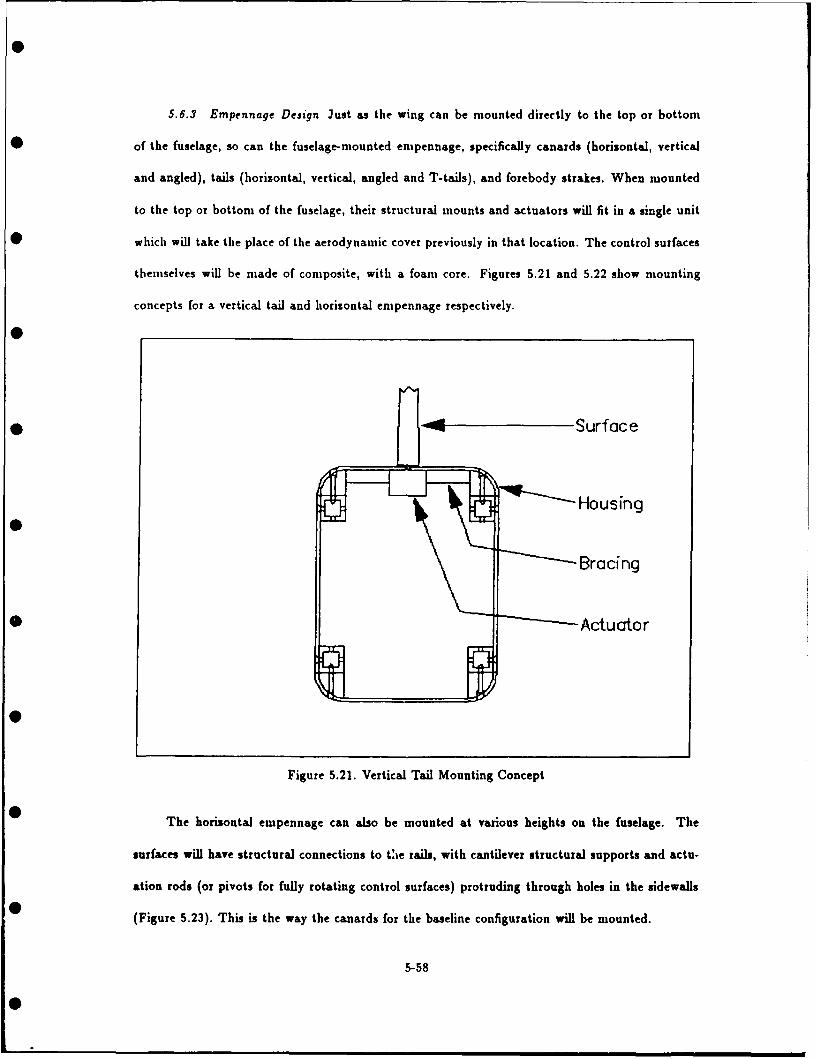
5.6.3 Empennage Design Just as the wing can be mounted directly to the top or bottom
of the fuselage, so can the fuselage-mounted empennage, specifically canards (horizontal, vertical
and angled), tails (horizontal, vertical, angled and T-tails), and forebody strakes. When mounted
to the top or bottom of the fuselage, their structural mounts and actuators will fit in a single unit
which will take the place of the aerodynamic cover previously in that location. The control surfaces
themselves will be made of composite, with a foam core. Figures 5.21 and 5.22 show mounting
concepts for a vertical tail and horizontal empennage respectively.
i -Surface
rth Hou sin g
'--- Bracing
_- --- Actucror
Figure 5.21. Vertical Tail Mounting Concept
The horizontal empennage can also be mounted at various heights on the fuselage. The
surfaces will have structural connections to tie rails, with cantilever structural supports and actu-
ation rods (or pivots for fully rotating control surfaces) protruding through holes in the sidewalls
(Figure 5.23). This is the way the canards for the baseline configuration will be mounted.
5-58

Surface
Figure 5.22. Horizontal Empennage Mounting Concept
5-59

Surface
•Bracin Actuator
Figure 5.23. Mid-height Horizontal Empennage Mounting Concept
A fuselage-mounted speedbrake can also be mounted on this fuselage design. It would be
mounted on the top of the fuselage by replacing one or more of the fuselage covers with the
speedbrake unit. The unit would mount directly to the tops of the rails.
5.6.4 Summary The fuselage will be of semfionocoque construction, consisting of four
longitudinal "rails", to which structural sidewalls and top and bottom fuselage "covers" will be
attached. Its approximate dimensions will be 12 inches wide by 15 inches tall. The wing will have
a monocoque design, with a foam core surrounded by a composite covering. It will be of one-piece
construction, with two parallel spars running spanwise. It will mount to the fuselage rails, on the
• top or the bottom of the fuselage. The wing will mount to the bottom of the fuselage on the
baseline MURV. The empennage (canards, tails, etc.) will also have foam cores with a composite
shells, and will mount to the top and/or bottom of the fuselage, or somewhere in between. For
S the baseline MURV, the single vertical tail will mount to the top of the fuselage, and the canards
5-60

0
will mount part way up the fuselage, just below the top fuselage rails. The engine and all other
* internal equipment will be installed inside the fuselage. This concludes the discussion of the MURV
structural design. The next section will discuss its modularity capabilities.
* 5.7 Modularity
Introduction This section will summarize the modularity capabilities of the MURV,
from both structural and electrical standpoints. It will then describe the arrangement of the in-
ternal equipment of the baseline configuration. It will also give an example of how the baseline
configuration could be transformed into a completely different "alternate configuration".
5.7.1 Structural Modularity The different components of the MURV (wing, engine, landing
gear, etc.) vary in how much they can be moved in or on the fuselage. The components and
structural members are broken into three categories, depending on their mobility: Fired Parts,
Parts with Placement Envelopes, and Parts with Random Placement. The Fired Parts are those
which have set locations in or on the fuselage, meaning their placement would not change from
configuration to configuration. They form the backbone of nonmoving parts to which the movable
parts attach. The Parts with Envelopes are movable, but their movement areas are limited to
certain "envelopes" on the fuselage. The Parts with Random Placement can be mounted anywhere,
so long as there is room for them.
* The combination of the fixed, envelope, and random components, and their locations, together
constitute the most generic description of the MURV design from a modularity standpoint. The
baseline configuration and the alternate configuration, described at the end of this section, are just
• specific incarnations of the general MURV design.
5.7.1.1 Fired Parts Very few of the items in the MURV have fixed locations, which
makes it extremely modular. By design, most of the structural parts are fixed, to form a framework
5-61

for component mounting and to minimize the changes in structural behavior from configuration to
• configuration. These items are the fuselage rails, the sidewalls, the nosecone, and the boattail. The
fuselage covers could not be fixed because their configuration depends directly on the location of
the wing, empennage, and any other externally mounted equipment.
Even though these items are "fixed", this does not mean that they will be identical through-
out all the potential configurations of the MURV. The rails will be fixed in that the distances
between the rails (both horizontally and vertically) will not change. Changing these dimensions
would require substantial modifications to various items, including the sidewalls and covers, engine
mounting frame, all internal bulkheads and stiffeners, equipment mounting racks, and the nosecone
and boattail. So while it would be possible to change the distances between the rails, the amount
0 of work required makes it very unlikely to happen as part of a "typical" modification to the MURV.
It will be possible to change the length of the rails and the sidewalls by the use of the rail and
sidewall joints described in Section 5.6.
The nosecone and boattail will only be fixed in terms of their location on the fuselage. The
entire nosecone and boattail sections can be replaced with different designs, the only requirement
being that they have the same interface dimensions where they mate with the main fuselage.
The video camera's location will also be fixed, which is in the bottom of the nosecone. This
is "fixed" only because it appears to be the best location at this point in the design, and there does
not seem to be any need to allow for movable placement.
The pitot tube, gyroscopes, and accelerometers also have "best" places to be located, and
hence fall into the "fixed" category. The pitot tube will be located on a boom extending from the
tip of the nose, and the gyros and accelerometers (referred to simply as "gyros" from now on) will
be installed in the fuselage covers above or below the fuel tank. This in order to have them as
close as possible to the vehicle center of gravity. If the wing were located such that one of its spars
interfered with the gyros, they could be moved to the cover on the other side of the fuselage. For
5-62
S"

example, for a low-mounted wing whose spar(s) passed under the fuel tank, the gyros could be put
* in the upper fuselage cover above the fuel tank.
Since the gyros will not be placed exactly at the vehicle center of gravity, their output will be
biased and will have to be corrected by the software in the data acquisition system. Depending on
0 the difficulty of this, it may be better to place the gyros at the vehicle center of gravity, and to have
the fuel tank be designed with a cutout so it could fit around them. Since different configurations
of the vehicle would have different center of gravity locations, the fuel tank and the gyros would be
0 shifted as a single unit to the various center of gravity locations. This would require a longer fuel
tank (reducing usable volume for other fuselage internal equipment and/or reducing the effective
fuel tank movement range) and special mounting considerations for the gyros. This tradeoff still
0 needs to be evaluated.
5.7.1.2 Parts with Placement Envelopes These items can be placed anywhere inside
their own regions of the fuselage, called "envelopes". The envelopes will be shown as shaded areas
over a side view of the fuselage, which is shown in Figure 5.24. In this figure, the fuselage is drawn
without bottom covers and with top covers, to illustrate their installation.
* The envelopes shown in the drawings in this section are not necessarily dimensionally exact;
they are shown to give an impression of the general range of movements of the components. When
actually installed in a particular MURV configuration, the components will only occupy a portion
of the space shown. Since the envelopes for different components will overlap, it will be up to the
person designing a new MURV configuration to come up with the best nonconflicting arrangement.
In reality, since the main fuselage has a constant cross-section, many of the items can be
* mounted anywhere along its length. But in this discussion, their envelopes were restricted to those
regions where the components would most efficiently be placed. For example, the fuel tank could
physically be mounted near the front of the aircraft, but this would cause the MURV center of
* gravity to shift during flight as fuel is consumed. So the envelope for the fuel tank is centered on
5-63

0
. Nosecone Covers
Rail Boattail
Figure 5.24. Fuselage Side View
the vehicle center of gravity, with only a few inches of movement allowed fore or aft. Since the
vehicle center of gravity can shift significantly from configuration to configuration, the actual range
of fuel tank placements is quite wide. This region is shown in Figure 5.25 as the shaded area. The
envelopes for the other components will be shown in the same manner.
The engine would also have an envelope in which it could be mounted, which is shown in
* Figure 5.26. The engine would be mounted in a frame, which would then mount to the four fuselage
rails. Its position could be changed by unbolting the frame from the rails, sliding the assembly
to a new position, and bolting it back down. In addition to holding the engine, the frame would
* add strength to the fuselage in that area. The aft limit to engine mounting would be determined
either by its getting too close to the walls of the boattail or by the rearmost frame-to-rail fastening
points reaching the ends of the rails. If the interference were with the boattail, the boattail could
* be modified or replaced with a new design to accommodate the engine. The engine is capable of
using different length nozzles, so the nozzle length could also be changed if necessary.
Since the fuel tank would need to be mounted close to the MURV center of gravity, the engine
* could only be moved forward to the point where the intake (bolted to the front of the engine) would
5-64

0
Figure 5.25. Fuel Tank Placement Envelope
0
Figure 5.26. Engine Placement Envelope
06
5-65

interfere with the fuel tank. The sloped front end of the engine envelope in the drawing represents
* the front edge of the intake, where it curves down and exits the fuselage. The intake would also
bolt to the lower two rails, at the point where it passes between them. The intake itself can also
be removed and replaced with a different design, if need be. It is not required to protrude out of
* the bottom of the fuselage - the removable sidewalls and covers allow for the intake (or intakes)
to exit the fuselage on the sides or the top as well.
The engine could also be replaced with a different model of jet engine, so long as the new model
had the same or smaller diameter. A different boattail is anticipated to match a different design of
engine. The design of the removable boattail also allows the possibility of using a propeller-type
engine. The propeller engine, installed in a pusher configuration, would be mounted in the same
location as the jet engine, but without a boattail. The length of the propeller may require the
landing gear struts to be lengthened, to insure that the propeller would not hit the ground.
The rear landing skids will fit in a housing, immediately behind the intake, on the underside
of the fuselage. Their basic location behind the intake does not change, but they may shift slightly
if the location of the inlet or the vehicle center of gravity moves.
The front landing gear can occupy the region shown in Figure 5.27. The actual location will
be determined by such factors as ground handling stability and interference with other items in
the MURV forward fuselage, notably the avionics computers. As with the other components, it
would mount to the fuselage rails. The front gear housing will probably only occupy a portion of
the volume in the bottom of the fuselage, as shown in the cross-section view in Figure 5.28.
The envelope for the wing consists of the areas above the top fuselage rails and below the
bottom rails, all along the length of the main fuselage (Figure 5.29). Wings with any planform can
be mounted, as well as ones with dihedral or anhedral. And more than one wing can be installed,
as in the case of a joined wing configuration. The main interference concerns are with the intake
and the front gear. The wing would have to be designed so that its spars do not interfere with
5-66

Figure 5.27. Front Landing Gear Placement Envelope
0
Figure 5.28. Cross-sectional View of Front Gear Envelope
5-67

either of these.
Figure 5.29. Wing Placement Envelope
The empennage could be mounted all along the top and bottom of the fuselage (horizontal,
vertical, or angled surfaces), as well as along the sides of the fuselage (horizontal surfaces only), in
the areas shown in Figure 5.30. The horizontal surfaces could not be mounted at the same height
as the fuselag-" rails, because the rails would interfere with the control surface actuation linkage or
pivots. The regions are at either end of the fuselage, and not in the middle, so that the empennage
can provide a torque around the center of gravity for vehicle control.
There are several interference concerns, the first of which is that any rear ventral fins will
have to be specially designed so as to not interfere with the deployment of the landing skids. Also,
the placement of a mid-height horizontal tail will be limited by interference of its interior actuators,
bracing, etc., with the engine. Twin vertical surfaces can be mounted on either side of the front
gear, but they will have to be designed so as to not interfere with the operation of the gear. And
finally, the design of vertical surfaces mounted in the same area as the wing will need to take into
account the fact that the fuselage rails will be "covered up" by the wing rails in that area. The
surfaces could be designed to attach directly to the wing rails, for example.
5-68

Figure 5.30. Empennage Placement Envelope
The last components which could be mounted in a general region of the fuselage are the
avionics computers. In this context, the term "avionics computers" refers to the on-board portions
of the flight control and data acquisition systems, not including sensors or actuators. They will
occupy the unused open volume inside the fuselage, forward or aft of the fuel tank. This also
includes any unused volume in the nosecone. This envelope is shown in Figure 5.31. Since the
envelopes for the avionics computers and the fuel tank overlap significantly, they will trade off
space with each other. Moving the fuel tank forward will probably require moving some of the
avionics equipment behind the fuel tank, and vice versa. The other major interference problem was
already mentioned, with the front landing gear. The front gear housing probably will not reach
from wall to wall in the bottom of the fuselage, so some of the avionics equipment could fit on
either side of it, if necessary.
* 5.7.1.3 Parts with Random Placement This last category considers those components
which could be placed virtually anywhere in the fuselage. They are: batteries, antennas, sensors,
ballast, and fuselage bulkheads and stiffeners. The batteries, antennas, and sensors could be placed
* in the empty space inside the fuselage covers, nosecone, and around the intake, between where it is
5-69

0
Figure 5.31. Avionics Computers Placement Envelope
attached to the engine face and where it bends down and exits the fuselage. The ballast could also
be put in any of these areas, but it will most likely be placed in the nosecone to have the greatest
effect on the MURV center of gravity. The bulkheads could be placed where necessary, and could
be tailored to fit around any interfering equipment. The stiffeners will attach to the rails, and
provide strength around the perimeter of the fuselage. They could be placed in any location where
there was no interference.
5.7.2 Aero Shella The baseline MURV will not require aero shells, but they can be added
later if desired. The shells will be made up of styrofoam sections which will attach to the outside of
* the fuselage to form a smooth aerodynamic surface. A typical concept is shown in Figure 5.32. One
method of attaching the shells would be to hold them temporarily in place with rubber cement,
and then cover the joints with heat-shrink tape and heat it to seal the shells in place. The tape
* could be cut along the joints to remove the shells. To replace the shells, new tape would be applied
and heated. If the shells were covered with a surface from which the old tape could be removed
before adding new tape, the shells could be reused indefinitely. If not, this process would lead to
* an eventual buildup of tape, and new shells would need to be made.
5-70

. . . . . .
...0. . .
. . . . ..0. .
.
........ Aero shells
* Figure 5.32. Aero Shell Mounting Concept
5-71

Covering the MURV with aero shells may require modifying the landing gear, aerodynamic
surfaces, and the nosecone and boattail to insure the best aerodynamic shape and no movement
interference.
5.7.3 Electrical Modularity The electrical modularity feature of the MURV consists of two
areas: power supply and signal distribution. The power supply will be modular in that additional
batteries can easily be added to the main and backup power sources if necessary. The modularity
of the signal distribution system is more complicated.
Tlhe "signal distribution system" refers to the wires running between the onboard avionics
computers and the actuators and sensors. The wires will be fitted with metal contacts, which will fit
into plastic or metal connectors. The connectors will range from single wire capacity up to perhaps
thirty or forty wire capacity at the computer interfaces. The individual wires will be detachable
from the connectors. The connectors will also be easy to separate (thereby disconnecting all the
wires passing through them in one operation), to make components with many wire attachments
easy to remove. The bundles of wires extending down the length of the fuselage will not be covered
in sheathing, but they will be routed through wire bundle holders, stationed at intermittent points
along the length of the fuselage.
5.7.4 Internal Arrangement Once all of the locations for the different components in the
fuselage had been established, the optimal internal arrangement of those components was defined
for the baseline configuration. This arrangement is described below.
The fuel tank center of gravity needed to be located as near to the center of gravity of the
MURV as possible, to niininmize center of gravity travel as fuel is consumed. Another objective
was to allow the fuel tank to be movable fore/aft in the fuselage, so that it could be shifted to
coincide with thf center of gravity of each particular MURV configuration Preliminary analyses
for two potential baseline configurations indicated that the fuel tank needed to be immediately
5-72

0i
(approximately one inch) in front of the intake (Volume Two, Figures 2.2 and 2.3), and for the third
* configuration it needed to be further aft but the intake was in the way (Volume Two, Figure 2.4).
This indicated that the fuel tank should be mounted immediately forward of the intake. It would
be placed between movable bulkheads which would give the fuselage strength and keep the fuel
* tank from sliding back and forth during maneuvers. Flat sheets or "pans" would also be placed
above and below the fue' tank to hold it'in place in the vertical direction.
The objectives for the positioning of the rear landing gear were to minimize the form drag in
* the stowed position and to minimize the nose-down torque on touchdown. The landing gear was
designed as tricycle-type, with the rear gear (skids) touching down first on landing. The friction of
the skids on the runway would create a tremendous torque on the MURV, forcing the nose down
very quickly, thus requiring a very substantial nosegear to avoid damage. The objective to minimize
nose-down torque on landing pushed the rear gear location forward on the fuselage, towards the
center of gravity, to minimize the moment arm of the landing friction when the rear skids touch
* down.
But the intake, protruding down out of the fuselage, limited how far forward the rear gear
could be stowed. So the position of the rear gear was determined to be immediately behind the
intake on the underside of the fuselage. Postioning the gear at this point and having the skids, when
stowed, reach from the bottom of the intake to the fuselage underside, had the added benefit of
"filling in" the area behind the intake, forming a smooth path behind the intake for the airflow, thus
reducing form drag. The section on Wing Structural Design/Mounting explained how the MURV
would have one or more wing spars crossing the fuselage. In order to eliminate the possibility of
the spars of a bottom-mounted wing being in the way of the pivot path for the landing gear, the
gear pivot point was designed to be under the plane of the wing spars.
The objective for the location of the front gear was to maximize the stability of the MURV
during ground handling. This pushed the gear pivot location forward, as far from the MURV
5-73

center of gravity as possible. But the overall objective of minimizing interference among subsystems
* required that the forward gear not impact the nosecone design. This placed the retractable gear
in the front of the main fuselage, immediately aft of the nosecone joint. The gear could be moved
slightly aft if needed due to interference problems with the avionics computers, so long as ground
handling stability was maintained.
The TV camera needed to provide the best field of view for the pilot, especially for landing.
In order to provide a good view for landing, the camera needed to be somewhere along the bottom
* of the MURV, looking slightly downward. Putting the camera in the bottom of the main fuselage
would cause interference problems if the wing or other control surfaces needed to be mounted ill
the same area. So the camera would be mounted in the bottom of the nosecone, looking slightly
• downward through a window.
In some configurations, the center of gravity may be too far aft for stability or fuel tank center
of gravity mismatch reasons. In these cases, one remedy would be to add ballast. In order to move
* the center of gravity as far forward with the minimum weight of ballast, the ballast would need to
be as far forward as possible, in the nosecone.
Many internal components did not have any requirements as to their location. For the baseline
MURV, this included onboard computers, batteries, and some sensors. Other configurations may
require various kinds of parachutes (main, drogue, or spin recovery), extra computers, extra sensors,
recorders, etc. These items could be located in the remaining open areas in the fuselage. The only
large open area remaining was the area forward of the fuel tank, including the open area in the
nosecone. So this area would be the location for the bulkiest components, most likely the main
computer. It should be noted that the wheelwell for the nosewheel would occupy some of this space,
possibly creating some interference problems. The smaller components could be placed in almost
any open space in the fuselage, notably the area above the sloped portion of the intake and the
unoccupied volume in the fuselage top and bottom covers. A drawing of the internal arrangement
5-74

of the baseline configuration is shown in Figure 5.33.
0 Although they are not actually components, the locations of the sidewall joints also needed
to be established for the baseline MURV. Two sidewall joints (on opposite sides of the fuselage)
would be placed between the front end of the fuel tank and the avionics computers. This is for two
0 reasons. First, it allows the sidewalls covering the avionics computers to be removed (for access)
without removing both entire sidewalls. Second, if the location of the canards were to be changed,
that section of sidewall would have to be replaced with one with the proper hole locations for the
! •actuator pivots. A joint allows replacement of a short section, instead of the entire sidewall.
This section explained how the internal arrangement of the baseline MURV was developed.
A similar line of reasoning would be followed to establish any internal arrangements for different
MURV configurations.
5.7.5 Application of Modularity Features into Baseline and Alternate Configurations The
* purpose of this section is to describe the baseline configuration and an alternate configuration of
the MURV design. It will explain what work sould be required to change the baseline into the
alternate, as an illustration of the modularity of the MURV.
5.7.5.1 Baseline Configuration The baseline configuration is shown in Figure 5.34. Its
internal arrangement was just described, and its external arrangement is summarised here: it will
have a low, delta wing, with a fully pivoting canard mounted just below the top fuselage rail. There
will also be twin ventral canards on the bottom of the front fuselage, angled 30 degrees outward
from vertical. It will have a pair of horizontally acting speedbrakes installed in the boattail. It
will not have any external aero shells. It will have a single Teledyne Model 320 turbojet engine,
without thrust vectoring.
5.7.5.2 Alternate Configuration In order to best illustrate the modularity of the MURV,
* an alternate configuration was chosen that would use as many of the modularity features as pos-
5-75
0

C)0
CfU)
* HcnI ~ \j
\i~\ 5-76

Speedbrake
Hor~zontal Canard
**", Ventral Angled Canard
* Figure 5.34. Baseline Configuration
5-77

sible. Admittedly, some of the features are arbitrary, included just to illustrate modularity. This
0 alternate configuration is shown in Figure 5.35.
Thrust vectoring paddles
0
0
0 Speedbrake
Forebody strake
Figure 5.35. Alternate Configuration
* The alternate configuration has a joined wing configuration, with a front-mounted, low, swept
front wing which is joined at the wingtips with a rear-mounted, high, forward swept rear wing. It
has wingtip vertical surfaces which join the wingtips of the front and rear wings. It also has
* forebody strakes (for generating vortices), which would be used along with the wingtip surfaces for
yaw control. The fuselage is lengthened to accomodate the forebody strakes. It is also fitted with
stryofoam aero shells to produce a different aerodynamic shape. The nosecone would be replaced
* with one that incorporates this shape, and the aero shells would not "begin" until just behind the
nosecone.
The new configuration is fitted with an uprated Teledyne turbojet engine, with a larger intake
* and paddle-type thrust vectoring. Since the higher thrust engine allows for a heavier MURV and
5-78
0

also leads to a higher landing speed, the alternate configuration includes a large fui.elage-mounted
* speedbrake. The higher thrust engine also consumes more fuel, so the fuel tank is larger. The thrust
vectoring mechanism is heavy, so ballast is required in the nose to keep the center of gravity forward
and the MURV stable. The particular load distribution of the alternate configuration makes sonle
stiffeners between the fuselage rails necessary.
5.7.5.3 Summary of Work Required to Transform the Baseline into the Alternate Con-
figuration In order to turn the baseline MURV into the alternate configuration, both hardware and
software would have to be changed. Discussing software first, the most basic change would be that
the flight control laws in both the ground and flight computers would have to be changed to reflect
the new aerodynamic configuration. Also, the software in the data acquisition system controlling
the multiplexing and demultiplexing of the telemetry signal would have to be changed to incorpo-
rate the larger number of on-board actuators (for the thrust vectoring system and strakes, among
others).
Now, the hardware will be addressed, in a rough chronological order. First, all of the top and
bottom fuselage covers, including the flush covers mounted to the wing rails, would be removed for
access. Then the engine would be replaced.
The first step in removing the engine would be to separate the intake from the engine, detach
it from the fuselage rails, and remove it by sliding it out through the opening between the wing
rails. The boattail would then be removed by unbolting it from the ends of the fuselage rails, and
then the old engine and its frame would be removed by detaching them from the fuselage rails and
sliding them out the rear of the fuselage. The new engine and its frame could then be slid into
position in the end of the fuselage and fastened to the rails. The new boattail, with its thrust
vectoring mechanism, could then be bolted to the ends of the fuselage rails. Next, the new intake
would be inserted into place in the fuselage through the opening in the wing, and bolted to the
front of the engine and secured to the lower fuselage rails.
5-79

The rear vertical tail and mounting assembly would then be removed by unbolting it from
• the upper fuselage rails. The rear landing skids and their housing would be detached from the
wing rails and/or lower fuselage rails. The delta wing would then be removed by unbolting its rails
from the lower fuselage rails. The two sections of the new joined wing would be attached to the
fuselage, the front wing to the lower fuselage rails and the rear wing to the upper fuselage rails.
The tips of the wings would then be fastened to the vertical wingtip control surfaces, forming the
joined wing. Then the rear landing gear assembly would be reattached to the lower fuselage rails.
* Its attachment to the fuselage might have to be modified, since the wing rails would no longer be
attached to the fuselage rails in that area.
Next, the avionics computers, front landing gear, and nosecone would be removed in prepara-
* tion for extending the front part of the fuselage. They would be removed by detaching them from
the fuselage rails. The sections of sidewall with the horizontal canards would be removed next,
by disconnecting their attachments to the rails and disassembling the sidewall joints immediately
* forward of the fuel tank. This would leave the four bare fuselage rails protruding forward, with
nothing connecied to them. The rails would then be extended by attaching short new sections of
rail to the ends of the existing rails using the fuselage rail joint design described in Section 5.6.
• First, the last holes in the ends of the existing rails would be drilled out, so that the bolts could
easily slide through them. Next, the new rail joint sleeves would be inserted into the ends of the
rails and secured by bolts going through the enlarged holes in the rails and threading into tapped
* holes in the sleeves. The new rail sections would then slide over the protruding ends of the sleeves,
and bolted down similarly.
Once the rails had been extended, new longer sections of sidewall would be fastened to the
* rails and the sidewall joints would be reassembled. The camera and other equipment would be
transferred from the old nosecone to the new one, and it would be attached to the ends of the rails,
at the front of the main fuselage. The avionics and front gear would then be reinstalled.
5-80

0
Next, the fuel tank would be removed. First, the flat "pans" above and below the tank would
* be removed. Then the tank would be compressed and pulled out through the fuselage rails. The
fuselage bulkheads which had been on either end of the fuel tank would be detached from the rails,
moved to their new positions, and reattached. The new fuel tank would then be set in place, and
* larger top and bottom pans installed. Next, the fuselage stiffeners would be installed, providing
more structural support to the rails.
The forebody strakes would be part of a unit which would then be installed on the top of the
* fuselage, immediately behind the nosecone. A concept of what the cross-section would look like
(after the foam shells have been attached) is in Figure 5.36.
Actuatortrk
Stra ke
* Aero shells
* Figure 5.36. Forebody Strakes Installation Concept
Next, the fuselage-mounted speedbrake unit would be mounted to the top fuselage rails,
behind the strake assembly. All the remaining equipment would be installed in the fuselage and
5-81

inside the recesses of the the new fuselage covers. Then the new covers, plus any old ones to
* be reused, would be installed on the fuselage. Finally, foam aero shells would be fabricated and
installed on the fuselage.
After the installation of the last aero shell, the MURV would then be in the new configura-
* tion. It would have a totally different outward appearance and many of the components would be
different, but the basic underlying structure would not have changed.
5.8 Remote Cockpit
The remote cockpit is that portion of the ground system which the pilot will use to fly the
MURV. It will not contain any other data displays - its only function will be to provide the pilot
with the controls and instruments necessary to fly the MURV safely and to perform flight tests. All
other functions of the ground station, such as real-time data display for analysis, data recording,
automatic flight control, and telemetry, will be performed by the other two systems in the ground
station, the data acquisition system and the flight control system. Only one person, the pilot, will
be required to actually fly the MURV. Other personnel (most likely including the student or faculty
member who designed the test) will watch the real time displays of the data acquisition system.
The cockpit will function as the interface between the pilot and these systems, which will
control the MURV via radio link. The cockpit will relay the pilot's control inputs to the ground
portion of the flight control system, and the data acquisition system will provide the flight data to
the cockpit in a form that the instruments can use directly. The commands which the flight control
computer will not control, such as landing gear deploy commands, will bypass the ground flight
control computer and be sent directly to the vehicle.
It has not been decided if the remote cockpit will be "custom built" for the MURV or whether
an existing RPV remote cockpit will be procured and modified. This section will describe what
features the cockpit should have, regardless of whether it is bought or built.
5-82

5.8.1 Overall Layout The remote cockpit will he used outdoors, rather than inside a vehicle
* or other shelter. It will not be a fully enclosed "mock cockpit", but instead be something that
could be mounted on a tabletop or be part of a console. It will not have rudder pedals, so all of
the controls (including rudder controls) will be worked by hand. It will have a handheld control
* box, connected to the main cockpit by cable, with the basic controls needed to takeoff and land the
MURV. This will either be an inherent part of the controls housing design or a unit with redundant
controls. The handheld box will allow the pilot to get up from his position in front of the cockpit
* instruments and visually follow the MURV when it is near the runway area.
5.8.2 Description of Controls and Instruments The cockpit will have a basic complement
of controls and instruments, which will be available regardless of the particular aerodynamic con-
figuration of the MURV or the test it is to perform. It will also have a number of "generic" controls
and instruments, which can be tailored to support a specific configuration or test to be performed.
The functions of these items would change from configuration to configuration, and from test to
test. In many cases, not all of the available instruments and controls will be needed for a series of
flights.
• 5.8.2.1 Controls
* Pitch/roll control (stick)
* Throttle/rudder control
* Front gear deploy
* Rear gear deploy
* Nosewheel steering engage/disengage
* Backup flight control system engage/disengage
• Initiate self-test
5-83

" Flight mode select-approximately 6 flight modes
* * Preprogrammed maneuver engage-approximately 4 maneuvers
" Approximately 10 return-to-neutral switches
The pitch/roll control will be a two-degree-of-freedom joystick, sprung to return to center in
both axes. It will not necessarily be for direct aileron/elevator control, but rather to send attitude
position or rate information to the flight control computer, which will translate it into actuator
commands for the variable control surfaces. The only directly controllable variable control surface
will be the rudder (or equivalent surfaces to be used for yaw control on other MURV configurations).
The throttle/rudder control will also be a two degree-of- freedom joystick. It will be sprung
• to return to center in the left/right direction and would remain in position in the forward/backward
direction. The rudder or equivalent control surface(s) will be controlled by the left/right movement
of the joystick. It will be directly controlled by the pilot when the MURV is in the "conventional"
• flight control mode. In this mode, the MURV will behave like a three-axis controlled aircraft,
like the majority of airplanes flying today. In an integrated control mode, the rudder may be
controlled automatically by the flight control system (to coordinate turns, for example), and the
rudder control on the cockpit console would have no effect. The throttle would be controlled by
the forward/backward movement of the joystick. It would be like a conventional aircraft throttle,
in which the location of the handle indicates the throttle setting.
* The landing gear controls will only deploy (not retract) the landing gear because the gear
are one-time deploy (no retraction) type. The nosewheel steering will be used during crosswind
takeoffs and landings, at the lower speeds where the rudders are ineffective. Engaging the nosewheel
* steering will allow the rudder control to be used to turn the dolly nosewheel during takeoff and the
MURV nosewheel during landing. The backup flight control system engage/disengage will allow
the pilot to command the backup flight control system to take over flight control of the MURV,
* and to disengage it and resume control.
5-84

The initiate self-test switch will be used to make sure the flight control system is working
* properly before each flight. It would cause the flight control system to perform automatic checks
of all the software, its interfaces with the sensors and actuators, verify the integrity of the primary
and backup control loops, and to cycle each of the control actuators on the MURV to verify proper
* operation.
The rest of the controls will be "programmable", to allow them to be used for different tests
or MURV configurations. For example, for a MURV configuration with a speedbrake, a particular
• switch could be used to extend and retract the speedbrake, and it would be labeled as such. But
for a new configuration which has retractable outrigger wheels on the wingtips, the switch could
be reprogrammed to extend or retract the wheels. It would be relabeled on the console, and its
• command signal would be rerouted by the flight control and data acquisition systems to activate
the proper servos on board the MURV.
The numbers of these controls which will be in the cockpit design are first estimates, based on
* the current design of the flight control system and a prediction of how many "extra" different types
of control surfaces or other devices that any one configuration of the MURV could have. These
numbers will probably change as the design is developed in more detail.
The flight mode select control will allow the pilot to switch among various "flight modes"
available in the flight control computer. The flight control system will have a default flight mode,
the "conventional" flight mode, introduced above. In this mode, the stick will control pitch position
and roll rate, and the rudder control will control yaw position. This flight mode will be common
to all configurations of the MURV.
The selector could also pick other flight modes, which would be programmed into the flight
control computer depending on the MURV configuration or tests to be flown. Examples of different
flight modes include pitch pointing, vertical translation, and direct sideforce modes. The computer
might or might not accept stick or rudder commands, depending on the flight mode. The pilot
5-85

would control the throttle level in all flight modes.
*The preprogranimed maneuver engage would allow the pilot to initiate a preprogrammed
maneuver stored in the flight control computer. Once a preprogrammed maneuver was initiated,
the flight control computer would not allow any control inputs from the pilot, such as stick or
*throttle commands. The pilot would be able to abort a maneuver by switching back to one of the
available control modes and taking over control. The baseline MURV will not have any prepro-
grammed maneuvers. A more detailed discussion of the flight control computer, flight modes, and
preprogranmed maneuvers is in Section 5.3.
The return-to-neutral switches will be used for discrete position (as opposed to variable po-
sition) control surfaces or other devices, such as parachutes. The switches will be used for both
* mechanisms or surfaces under the sole control of the pilot and ones which would be controlled by
both the pilot and the flight control computer. "Return-to-neutral" means that the controls will
not indicate the status of the surface or device by their position. This is to avoid conflicting switch
* and surface positions after the flight computer has changed the position of a control surface without
moving the switch on the cockpit console. The controls will be toggle switches which will be sprung
to return to a neutral position. They will have two energized positions (up and down) as well as
* the neutral position (center). The baseline will use three of these switches fcr speedbrake, flap, and
engine igniter control.
The control of flap settings will be used as an example of how these switches would be used.
The baseline MURV will have flaps which will have extended and retracted positions, as well as
some intermediate settings such as 10 degrees and 20 degrees. The pilot (or the flight computer)
will only be able to choose from these discrete settings. A single switch with two energized positions
would be used to control the flap setting. The switch would either step up or step down the flap
setting by one increment at a time, depending on which direction the switch was moved. If the
flaps were fully retracted and the pilot wanted to extend them to the 20 degree position, he would
5-86
0

push the switch up and allow it to return to center once (moving the flaps to 10 degrees), and
* repeat the movement (moving the flaps to 20 degrees). To retract the flaps, he would reverse the
procedure, this time pushing the switch down twice.
5.8.2.2 Handheld Boz Controls The controls needed for takeoff, landing, and flight
around the runway area will be included on the handheld control box. They are:
* Pitch/roll control (stick)
* Throttle/rudder control
* Front gear deploy
* Rear gear deploy
* Nosewheel steering engage/disengage
* 4 Programmable return-to-neutral switches
The baseline MURV will use two of the return-to-neutral switches for flap and speedbrake
control. The other programmable controls will not be used.
* •5.8.2.3 Instruments The cockpit will also include the following instruments:
* Attitude Direction Indicator (Artificial Horizon)
• * Airspeed Indicator
* Vertical Velocity Indicator
" Altimeter
" Angle of Attack
" Health indicators (all with audible alarm)
* - Uplink status
5-87

- Downlink status
0 - Flight control computer status
- Backup flight control system engaged status
- Backup flight control system health status
- Main onboard electrical power status
* Front gear position
9 Rear gear position
* Video
* e MURV location display
* 18 On/Off Indicators (including flight mode indicators and preprogrammed maneuver indi-
cators)
0 12 Graduated Indicators
The first five instruments are necessary to fly the MURV. The health indicators are used
to monitor the status of critical systems or components in the flight vehicle and ground systems.
They will all be connected to an audible alarm, which will sound for a few seconds if one of the
indicators is activated. The gear position indicators are used to inform the pilot of landing gear
• position during flight beyond visual range. The video display will show a black-and-white image
of the view looking out the nose of the MURV. It will help the pilot to understand the MURV
attitude during flight beyond visual range, and will also help him to line up on the runway during
* final approach.
The MURV location display will show the location of the vehicle in the test area. It will
show the MURV as a moving point or cursor, in reference to the ground station and possibly other
* landmarks. The area covered by the display will be large enough to cover the entire test area plus
5-88

a small overage to allow some margin of overshoot before the MURV leaves the screen altogether.
The tracking system, which will supply the position information to the display, is briefly described
in Section 5.9.
The remaining indicators will be used for different parameters, depending on the particular
MURV configuration or the test being performed. They will be of two types, on/off indicators
(such as lights) and graduated indicators (such as dials or vertical scales). Approximately six
on/off indicators will be used to show which flight mode the MURV is in, and approximately
four of them will indicate whether certain preprogrammed test maneuvers are in progress. These
numbers are based on the current estimates of the capabilities of the flight control system, and the
total numbers of the graduated and on/off indicators are estimates of how many will be needed
in order to accommodate all the potential configurations of the MURV. As with the numbers of
programmable controls, they will probably change as the design is finalized.
These instruments will be "programmable", in the sense that they will be used to display
different information for different configurations or tests. For example, the baseline MURV with
its turbojet engine would require an instrument to display the exhaust gas temperature. But a
propeller-driven configuration would not need exhaust gas temperature to be displayed, though the
pilot might need to know the cylinder head temperature. So the dial used to indicate exhaust gas
temperature would be relabeled and rescaled to indicate cylinder head temperature, and the portion
of the data acquisition system controlling the dial would be reprogrammed to send it cylinder head
temperature information.
For the baseline configuration, four of the graduated indicators will be used to show oil
pressure, exhaust gas temperature, flap position, and speedbrake position. One of the on/off
indicators will show engine igniter status.
There are also some instruments which would be good to have, but are not required for the
cockpit. These are:
5-89

* Sideslip angle
* Turn/slip indicator
" Machmeter
* G-meter
" Fuel level (including 'uel flowmeter status)
These would all help the pilot know the flight conditions of the MURV, but are not absolutely
necessary to fly the aircraft safely. For example, the pilot could fly the MURV for a specific time
duration rather than use a fuel remaining indicator to tell him how long he can fly. Their inclusion
in the cockpit design would not add any requirements to the data acquisition system, since all of
these measurements can be produced by the baseline data system without any new sensors. Using
the fuel level as an example, the computer would use the initial full level of the fuel tank and the
fuel flowrate to calculate the remaining fuel level. The tank full level is constant and could be
programmed into the computer, and the flowrate is already measured for other reasons.
This completes the discussion of the remote cockpit design. The development of this design
is discussed in Volume Two, Chapter VIII.
5.9 Tracking System
The tracking system will provide inputs to a display in the remote cockpit which will show
the postion of the MURV relative to the ground station at all times during flight. The display will
be an overhead view of the test area, showing the MURV as a moving point or cursor, plus the
ground station and possibly other landmarks.
It is quite possible that the tracking function will be provided by a portable radar unit at
Jefferson Proving Ground in southern Indiana (see Appendix N). If not, a tracking system will
need to be designed and included as part of the MURV ground system. It is not known if the
5-90

MURV will fly at Jefferson Proving Ground, or if the radar there can be used. So while the MURV
will definitely require a tracking system, the decision whether or not it will actually be a part of
the MURV ground system (and owned by AFIT) has not yet been made.
5.10 Reliability Summary
Introduction This section performs a basic reliability analysis of the preliminary
MURV design. Since the design at this point does not include any specific components (except the
* engine) or specify any safety factors in the structural design, the reliability analysis is limited to a
very general Failure Modes and Effects Analysis, resulting in a preliminary Critical Items List.
5.10.1 Failure Modes and Effects Analysis The MURV was analysed on a subsystem level
in order to develop the Failure Modes and Effects Analysis. Only the most probable failure modes
are included here, and only single failures are considered. The entries have the following elements:
e Failure mode
* Means of detection (in parentheses)
o Corrective action and/or effect
o Criticality level
The failure mode is a description of which item fails, how it fails, and any circumstances which
* would have an effect on the outcome. The means of failure detection refer to the way(s) that the
pilot would be informed of the failure. Most of these are indicators on the remote cockpit console.
For those failures in which the computer automatically takes corrective action, the computer's
* means of detecting the failure will not be listed. The effects and criticality level will be those
resulting if either the computer automatically takes corrective action or the pilot detects the failure
and takes proper corrective action. The criticality levels are defined as follows:
5-91

Criticality 1 Destruction of or major damage to MURV (includes uncontrolled crash or computer-
* controlled crash landing in a wooded area)
Criticality 2 Moderate damage to MURV (includes running off runway or crash landing on runway
or grassy area)
0Criticality 3 Loss of some test data (includes aborted flights)
Criticality 4 No significant effect (includes minor damage to MURV)
0. In these definitions, major damage means that many major components and/or structural parts
are damaged. Moderate damage means that one or two major components are damaged, and/or
the MURV cannot fly without repairs. Minor damage refers to mostly superficial damage which
*- does not preclude the MURV from safely performing flight tests.
5.10.1.1 Propulsion System
- Engine fails during takeoff roll (audible, engine RPM indicator, primary power status indica-
tor) Abort takeoff, vehicle possibly runs off end of runway. Criticality 2.
Engine fails immediately after liftoff (audible, engine RPM indicator, primary power status
indicator) MURV stalls and crashes. Criticality 1.
Engine fails at low altitude (ezhaust gas temperature indicator, engine RPM indicator, pri-
mary power status indicator) Automatic switchover to backup batteries, pilot looks for suit-
able landing area and performs a deadstick crash landing. Criticality 2.
Engine fails at high altitude (exhaust gas temperature indicator, engine RPM indicator, pri-
mary power status indicator) Automatic switchover to backup batteries, pilot puts vehicle in
a dive and restarts engine using igniter switch in the remote cockpit. Flight is aborted due
to drained backup batteries, with a controlled landing on runway. Criticality 3.
5-92

Engine fails on landing approach (audible, engine RPM indicator, primary power status indi-
cator) Automatic switchover to backup batteries, pilot performs a deadstick crash landing.
Criticality 2.
Engine fails after touchdown (audible, engine RPM indicator, primary power status indicator)
• Automatic switchover to backup batteries, normal rollout. Criticality 4.
Loss of primary electrical power (primary power status indicator) Automatic switchover to
backup batteries, mission abort, and controlled landing on runway. Criticality 3.
Engine throttle control fails (engine RPM indicator) Abort flight, pilot returns MURV to run-
way area and puts it into a racetrack pattern until the fuel runs out, then performs a deadstick
landing on the runway. Criticality 3.
exhaust gas temperature sensor output failure (ezhaust gas temperature indicator) Abort
flight, controlled landing on runway. Criticality 3.
* Fuel tank leakage (preflight fueling inspection) No flights until leak is fixed. Criticality 2.
Engine igniter failure (None) None - requires two failures, engine flameout and igniter failure.
Criticality 4.
Oil system failure (oil pressure indicator) Pilot shuts down engine, performs deadstick crash
landing. Criticality 2.
* 5.10.1.2 Launch/Recovery System
Flaps fail to deploy for landing (flap position indicator) Pilot lands MURV at higher speed,
vehicle possibly runs off end of runway. Criticality 2.
Flaps fail to retract after takeoff (flap position indicator) Flight can continue if flight can still
produce good test data; otherwise abort flight. Criticality 3.
5-93

Dolly rear tire blowout during takeoff (audible, visual) Abort takeoff, vehicle and dolly run
* off runway. Criticality 2.
Dolly nosewheel tire blowout during takeoff (audible, visual) Abort takeoff, vehicle and dolly
run off runway. Criticality 2.
Nosewheel tire blowout during landing (audible, visual) Vehicle runs off runway. Critical-
ity 2.
Front gear fails to deploy for landing (visual, front gear position indicator) Vehicle nose scrapes
on runway, vehicle possibly runs off runway. Criticality 2.
Gear deploys in flight while beyond visual range (front or rear gear position indicator) Pi-
lot would have to compensate for increased drag, and the flight could continue if the test data
were still valid; otherwise abort flight. Criticality 3.
Rear gear fails to deploy for landing (visual, rear gear position indicator) Underside of vehi-
* cle (including intake) scrapes on runway, vehicle possibly runs off runway. Criticality 2.
Nosewheel steering locks during landing rollout (visual) Vehicle runs off runway. Critical-
ity 2.
5.10.1.3 Data Acquisition System
Uplink failure (uplink status indicator) On-board backup flight control system automatically
* takes over, guides vehicle to a controlled crash landing if contact is not reestablished. Crash
landing could be in a wooded area, resulting in destruction of the vehicle. Criticality 1.
Ground power failure (all indicators go dead) Same as uplink failure above. Criticality 1.
Downlink failure (downlink status indicator) If MURV is within sight, pilot attempts to land
without instruments. If beyond visual range, pilot engages the BFCS and it guides the
MURV to a controlled crash landirg if contact is not reestablished. Criticality 1.
5-94
0

MURV flies beyond range (uplink or downlink status indicators) BFCS takes over, guides ve-
hicle to a controlled crash landing. Criticality 1.
Note: sensors which have been deemed critical for the operation of the main or backup flight
control systems will have redundancy (i.e. at least two of each). A single failure would cause the
_. •flight to be aborted, because only one would remain. Thus, they would be Criticality 3. Any
failures of the remaining noncritical sensors will either cause the backup flight control system to
take over, with a resulting flight abort, or will merely cause a loss of data. In either case, they
• would be Criticality 3 failures.
5.10.1.4 Flight Control System
* Control surface actuator failure (backup flight control system engaged indicator) Automatic
switch to the backup flight control system, mission abort, and controlled landing on runway.
Criticality 3.
* Central ground computer failure (Primary flight control system status indicator, backup flight
control system engaged indicator) Automatic switch to backup control system, mission abort,
and controlled landing on runway. Criticality 3.
* Primary flight computer failure (Primary flight control system status indicator, backup flight
control system engaged indicator) Automatic switch to backup control system, flight abort,
and controlled landing on runway. Criticality 3.
Backup flight computer failure (backup flight control system health status indicator) Flight
abort and controlled landing on runway. Criticality 3.
Primary-Backup computer interface failure (backup flight control system health status indi-
cator) Flight abort and controlled landing on runway. Criticality 3.
Note: control surfaces which have been deemed critical for the safe operation of the MURV
will have redundant actuators. A failure of one of these actuators will cause a flight abort because
5-95

0
there would be only one actuator left for that control surface. Therefore, all actuators for te
*' critical surfaces are Criticality 3. Noncritical surfaces will not have redundant actuators, but a
failure of one of them would result in a flight abort in the worst case. So all of the actuators will
be Criticality 3 or "better".
05.10.2 Critical Items List The Critical Items List is just a recap of the most critical failure
modes, the Criticality 1 failures. These would result in major damage to or destruction of the
MURV, and are:
S
" Engine fails immediately after liftoff
" Uplink failure
* Ground power failure
* Downlink failure
*= * MURV flies beyond range
The first and last of these will be difficult, if not impossible, to eliminate. The other three could
be eliminated through redundancy. The decision of whether to make these systems redundant or
not has not been made.
00
S
5-96

VI. Implementation Recommendations
Introduction The MURV-320 was carried to an early stage of preliminary design.
The overall shape and size of the vehicle were defined, and the wing and primary control surfaces
were sized and located on the fuselage. Several areas of detailed design work remain before the
MURV-320 is ready for operational use. This section provides a brief decription of several follow-on
efforts required for the definition of the external arrangement and the vehicle size. This list is not
intended to be complete, as several design iterations are still required in the detailed development
of the vehicle. Also, unanticipated requirements might be added to the MURV concept which could
alter the preliminary configuration description recommended here. Those described here represent
at best a minimum number of studies required in approaching a complete definition of the system.
6.1 External Arrangement and Vehicle Sizing
* 6.1.1 Refined Weight Estimate The weight estimates of this study were conducted with
incomplete knowledge of the subsystems' designs and weights; in fact, it was not pos.iible or logical
to define all of the necessary components at this stage of development. A follow-on study is required
to define the subsystem and component weights (and volumes) and identify the distribution of
those weights throughout the vehicle to obtain an accurate estimate of the center of gravity. This
knowledge should be made available to the aerodynamics and stability and control engineers to
determine the aerodynamic moments generated during flight. The movement of the center of
gravity as fuel is burned should also be determined.
6.1.2 External Arrangement
6.1.2.1 Wing Section Design A study is needed to investigate more recently developed
wing sections for possible inclusion into the MURV wing design, and to determine the optimum
* wing thickness ratio, t/c. The NACA 64 Series airfoil, though it is a good design by aerodynamic
6-1

0
standards, was not optimized for low speed flight. A review of newer technology airfoils could
• identify one or more wing sections with superior low speed aerodynamic qualities. The measures of
interest should be the lift curve slope, CL,., the maximum angle-of-attack before stall, and the post-
stall lift characteristics. These qualities should be examined to identify an airfoil which behaves
1 •most optimally during a post-stall maneuver at extreme angles-of-attack. Additionally, the wing
thickness should be optimized to reduce the structural weight while maintaining adequate strength
and volume.
6.1.2.2 Wing Planform Shaping For the baseline wing shape, tie trailing edge was
set normal to the flow direction, i.e., a sweep of 00. Alternate trailing edge sweep angles should
be investigated for optimal high angle-of-attack conditions. Wing twist should be considered to
control the spanwise flow and induced drag at high pitch angles.
6.1.2.3 High-Lift Devices Design A great deal of detailed design work is needed to
* •complete the high-lift devices design, particularly since the MURV is to perform supermaneuvers
requiring unconventional control surface implementation. The trailing edge flaps must be sized
to meet the takeoff and landing distance constraints for all potential weight conditions. They
_ •should also be optimized to augment the vehicle maneuvering capability during post-stall, and
more conventional, maneuverability flight tests. The ranges of angle-of-attack to investigate should
go above 700, and at least 100 of yaw. The deployment schedules for these devices must be developed
* for takeoff, landing, and extreme pitch angles, as a minimum. Flight envelope restrictions for device
deployment, such as a dynamic pressure limit, must be identified as well.
6.1.2.4 Lateral/Directional Control Surface Design The nontrol surfaces of the rec-
ommended design address longitudinal stability and control primarily. Lateral motion (rolling)
and directional motion (yawing) must be fully addressed before the vehicle design is completed.
The aileron design must be refined to provide the rolling moments needed, possibly augmented by
6-2

other control surfaces such as the rudder, to achieve a desired roll rate. The rudder design must
* be optimized to ensure there is adequate control authority in yawing and rolling motion to avoid
instabilities at all normal flight conditions, particularly at high angles-of-attack. It must be noted
that any such design work will apply only to the baseline configuration, the MURV-320. As the
• vehicle is modified for a different set of experiments, all control surface designs must be reviewed
for compatibility with the new configuration and redesigned as necessary.
6.1.2.5 Subsystem Integration As the MURV subsystems mature and their weights,
volumes, and locations become better defined, the external configuration must be refined accord-
ingly. Attention must be given to the location of sensors, onboard computer hardware, transmission
and receiving antennae, and all other internal components. As the configuration is refined, the vehi-
cle performance must be reviewed to ensure that the system meets the requirements and objectives
identified throughout this document.
6.2 Aerodynamics
The aerodynamic analyses conducted thus far have been adequate to obtain a first-order
approximation of the lift and drag characteristics of the MURV-320 configuration. A significant
number of detailed analyses of the aerodynamics of the design are needed before the design can be
completed. Rather than pinpoint specific parameters to investigate, an approach to the aerody-
namic analyses required is provided here.
6.2.1 Computational Flow Analysis A computerized model of the vehicle configuration
should be generated to perform computational fluid dynamic analyses. The analyses should deter-
* mine the MURV-320 lift and drag characteristics, the drag polar, thoughout the flight envelope.
Additionally, surface pressure distributions should be generated to identify potential areas of flow
separation and high turbulence, and to optimize the location of sensors. The effects of deployed
* control surfaces should be analysed for adverse aerodynamic effects. The model should generate
6-3

the aerodynamic (static) stability derivatives for use in a stability analysis of the vehicle. The
model could be used in investigating alternative vehicle configurations, so long as the configuration
changes are not extreme.
6.2.2 Wind Tunnel Tests Though a mathematical model is convenient for certain types
of aerodynamic studies, there are areas where the model will prove inadequate for analysing the
vehicle aerodynamics and stability and control. These areas generally occur at extreme attitudes
where vehicle control is paramount. Therefore, prior to flight testing, a wind tunnel test should be
performed with a scale model of the complete vehicle. The purpose of the test should be to reduce
the risk of flight and to investigate areas where the computational analyses are inadequate, such as in
regions of high turbulence or flow separation. The tests should investigate the forces and moments
generated in normal flight, maneuvering flight, and in the takeoff and landing configurations as
well. All potential control surface deflections, including simultaneous deployment of several surfaces,
should be tested. Since the vehicle is expected to operate at extreme attitudes where flow separation
is a strong possibility, water tunnel tests are also recommended to qualitatively investigate the flow
qualitities at such conditions.
If thrust vectoring is to be added to the design, a test should be performed dedicated to
investigating its effects on vehicle aerodynamics, stability, and controllability. The purpose should
be to determine the change in vehicle lift, drag, and moments for all phases of flight, including
takeoff, landing, and extreme maneuver conditions. The effect of the redesigned engine exhaust
nozzle should be investigated initially, without considering vectoring capability. The effects of
vectoring on lift and drag should be tested as a function of mass flow rate through the nozzle, since
a deflected nozzle asserts a vertical force on the vehicle, and the force is a function of the mass
flow rate. The resulting change in the stability derivatives must be determined and fed into the
stability computer model for analysis and for flight control system development.
6-4

6.3 Propulsion System
• The follow on efforts for the propulsion system focus mainly on the final selection of the
engine and resulting integration. Further refinement will have to be done in the detailed design
phase as the subsystems evolve from the functional preliminary designs to the detailed hardware
* designs to be implemented.
6.3.1 Turbojet Engine Selection The Teledyne Models 312 and 320 were rated the best for
the vehicle in the engine selection process discussed in Volume Two, Section 3.1.2. These two engines
were used to develop subsystems and to do performance analysis on the aircraft configurations.
Based upon the ability of the Model 320 to better satisfy the system objectives, it was chosen as
the recommended engine to be used in the detailed design phase of the MURV project. A survey
of newly developed engines should be made before final engine selection during the detailed design
phase to determine if a better powerplant has become available. The Teledyne growth engine may
be available at that time and should be considered as an alternative to the current design.
6.3.2 Engine Integration Once the final engine selection has been made, the propulsion
subsystems must be reexamined. The inlet design has been based upon data supplied by Teledyne
CAE specifically for the Model 320 engine. If another engine is selected, then the inlet must be
redesigned to meet the required airflows. A detailed thermodynamic analysis needs to be performed
based upon temperature data from the manufacturer. The analysis will determine the amount of air
* needed for cooling to prevent damage to the engine compartment sidewalls. This airflow will need to
be factored into the inlet design to control the throat Mach number and efficiency. Another aspect
of inlet design which should be analysed is the effect on pressure recovery of adding supplementary
• blow-in doors to the bottom of the inlet. During high angle-of-attack flight conditions, the blow-in
doors would allow auxiliary airflow, possibly preventing an engine flame-out. The boundary layer
diverter will be mounted to the fuselage rails, and the inlet duct will be mounted to the boundary
* layer diverter and the engine face. The details of the mounting need to be addressed after the final
6-5

0
engine selection.
* After the inlet design is finalized, the pressure recovery of the inlet must be predicted and
used to determine the installed thrust of the vehicle. The inlet drag will need to be calculated and
used with the installed thrust to define the predicted aircraft performance envelope.
All other subsystems will have to be reexamined as well. The fuel tank wil need to be sized to
meet the flight requirements of 25 minutes at full thrust plus a reserve. The fuel delivery system has
been designed for the Teledyne engine with an internal fuel pump. Other engines may require an
external fuel pump and different throttle control interfaces with the flight control system. During
the final aircraft component placement, the convergent nozzle length will be determined, and the
nozzle can be ordered at the same time as the engine.
The engine mount must be designed for the specific engine selected, and an analysis must be
done to determine the loadings the engine will transmit to the fuselage rails. The engine starting
system needs to be integrated into the fuselage structure. An access panel is required with a quick
disconnect fitting for the impingement air hose. The engine starting procedures and maintenance
schedules will have to be worked out with the engine manufacturer.
The types of materials for the subcomponents must be analysed and selected to meet the
needs of the designs. For example, the inlet duct may need to be formed out of high temperature
KEVLAR or other composite materials, depending on the temperature at the engine face.
* 6.S.3 Electrical Power System The electrical power requirements must be determined after
the data acquisition and flight control systems are finalized and subcomponents are selected. The
alternator output from the engine and the electrical needs of the aircraft will be used to deter-
* mine the amount of auxiliary power and associated discharge rates required from batteries. This
information will help determine the type of cells used in the battery. The size, weight, and cost
of the battery pack can then be determined. During the detailed design of the flight control sys-
* tem, the power requirements foi the flight critical systems can be determined and used to size the
6-6
0

01
backup battery system. Depending on the space and weight limitations of the final MURV design,
4 the decision will have to be made to incorporate the backup battery system with the auxiliary
power system to save space and weight. The weight savings must be traded off against the higher
reliability and cost of an independent tertiary system.
06.3.4 Propulsion System Summary The follow on work for the propulsion system will de-
pend upon the final engine selection. If the recommended Teledyne Model 320 is selected, the
required follow on work will be minimized. Any other engine selection will force a step back to
0reexamine and redesign the major engine subsystems. After the final selection, the detailed design
and analysis of the inlet, nozzle, fuel, and electrical systems must accomplished and finalized.
6.4 Control System Implementation
The efforts to this point have been conceptual in nature. There are several distinct areas
requiring more detailed treatment to define the specifications of the flight control system, the
most important of which is software support environment to provide the necessary models for each
element of the system. The following areas should be characterized and form the basis of a system
model.
1. Aircraft dynamics
2. Spectrum of disturbances
3. Actuator and motor dynamics
4. Sensor and digital-to-analog conversion dynamics
5. Telemetry transmission model
6. Digital-to-analog conversion dynamics
7. Aircraft model
6.4.1 Data Sampling Rates The required sampling rates will need to be analysed. This will
require a the use of the MURV system model [51]. The system response, the desired performance
goals and the computational capability of the selected flight computer will be used to bound the
6-7

sampling time. The desired aircraft performance measures and disturbance models are available in
• MIL-F-8785C and AFFDL-TR-76-125. Aircraft dynamics will be MURV configuration dependent
and are specified by their perturbed equations of motion. Components of the flight control system,
such as actuators, motors and sensors, each have dynamic characteristics usually documented in
* specification sheets. For preliminary performance analysis standard models of these components
are employed. The telemetry links introduce dynamics and also introduce a detrimental time delay.
Finally, highly complex control laws and a high fidelity aircraft model increase the computational
load of the central computer and increase the total computation cycle time.
A key assumption made in the development of a sampled-data control system is that of
infinitesimal processing time. This stipulates that the A/D and D/A conversion times and the
0 computation time is much less then the sampling time,
T'a/d + 'rc, p + Td/. << T
The upper limit to sampling time is defined by Shannon's sampling theorem [44],
IT>wf.
where w, is the bandwidth frequency of the input signal. This is the maxinum sampling time
allowed to reconstruct the sampled sensor signal.
One way to analytically evaluate a candidate sampling time is to develop a Z-plane represen-
tation of the closed-loop MURV system. A trial and error approach to sample time determination
is common; typically a sampling frequency of 10 times the highest frequency of the sampled input is
tried initially. An alternative method utilizes the stochastic system dynamics and knowledge of ex-
pected stochastic disturbances to determine the error growth rates in the state measurements [14].
Given an acceptable error limit, the sampling time can be determined.
6.4.2 Measurement Accuracy and Error The characterization of measurement noise, data
* word length, method of A/D conversion and the structure of the control law should be specified.
6-8

The effects of these should be compared to a set of performance requirements and modification
made as required. A complete error analysis includes the following.
1. Identification of required measurements
2. Characterization of sampling rate effects on control laws
3. Characterization of effects of measurement accuracy on control laws
• 4. Characterization of effects of measurement error on control laws
The effect of each error source on system performance call be evaluated once an error model
is defined with the following assumptions [44].
1. The error sequence is a stationary random process
2. The error random process has a uniform probability density function
3. The error is linearly independent of the sampled signal
* 4. The error random variables are linearly independent
6.4.3 Data Interface Requirements As the design develops there could be new data require-
ments for the flight control system. The data acquisition system and remote cockpit development
should be closely integrated with the control system. The use of redundant sensors should be re-
quired. The primary and backup flight controllers should be capable of checking data quality and
selecting the operational sensor once a sensor fails.
6.4.4 Control Surface Requirements Based on the MURV flight envelope, an aerodynamic
model of the configuration and handling quality specifications, actuators can be specified. The
* designer should select feasible actuators based on a study which trades minimum weight and volume
of the flight control system against minimum power requirements. Flight critical actuators should
have redundancy. Once weight and volume estimates are made, the data will be provided to the
* configuration, power distribution and data acquisition system designers.
6.4.5 Flight Control Computers Computer requirements will be defined in terms of clock
speed, read only memory capacity, random access memory capacity and the word length of internal
6-9

registers and the data interface bus. The design factors can be specified when sampling time,
* accuracy requirements, control system performance requirements, control law complexity and flight
computer programs are developed.
6.4.6 Control Law Development Control law development begins with specification of the
MURV system model. Once the design principle is selected and the state variables are identified
the performance requirements must be identified. One purpose of the MURV is to utilize advanced
control concepts relating to jet fighter performance. The military specification "Flying Qualities of
Piloted Airplanes", MIL-F-8785C, and "RPV Flying Qualities Design Criteria", AFFDL-TR-76-
125, provide desired RPV response characteristics for particular flight phases under various flight
conditions [26,80]. The main difference between these specifications concerns the effect of a remote
pilot.
"RPV stability and response requirements for manual control are expected to be differ-ent from those of piloted aircraft. The limitations of the visual displays and the absenceof kinesthetic motion cues are expected to result in different, if not more restrictive, lim-
* itations on the stability and response parameters [74]".
6.4.7 Control Law Interface Considerations The control laws developed should satisfy the
mission requirements. For the MURV the mission requirements will vary possibly requiring different
control laws. The complexity of the control law should be compatible with the the data sampling
rates and the computational capability of the flight computers.
6.4.8 Onboard Control System Considerations Once on-board computer specifications are
determined and the actuator system is specified the detailed architecture of the on-board flight
control system should be developed. Once completed these specifications should used to identify
* possible hardware components and their associated power, weight and volume estimates. The
estimates should be provided to the configuration, data acquisition system and power distribution
system designers.
6-10
01

6.4.9 Backup Control Modes The DFCS designer should develop appropriate control modes
* for implementation on the backup flight computer. The identification of flight critical sensors and
actuators is important for this process. Flight critical sensors are used to support the backup
control laws. Changes in these control laws should be provided to the data acquisition system
* •designer.
6.4-.10 Implementation Summary The items discussed here are the stepping stones for future
design efforts. The important tasks are the specification of the aircraft model and the development
of a system model to support the efforts described in this section. The specification of actuator
requirements, data sampling time for the primary control loop and flight control system components
are the more critical are the next steps. The results of each effort should be fed back into the design
process to address potential changes in interface requirements.
6.5 Launch/Recovery System
Before any detailed design of the launch and recovery systems can be started a considerable
amount of work on the final configuration needs to be finished first. Included in this work would
be:
1. Refinements of the aerodynamic characterics of the MURV (see Section 6.2).
2. An accurate estimate of the c.g. locations for the most forward and aft positions on the
MURV based on refined weight estimates.
3. A structural analysis (NASTRAN or a comparable finite element analysis program) of the
structure of the MURV, particulary in those areas that impact the LRS attachment locations.
4. An accurate estimate of the locations and volumes required for all internal and external
components (in particular the inlet).
6-11

0!
Once the results of these analyses are available the detailed design of the launch and recovery
• systems can begin. Included in this work are:
1. Refined estimates of the takeoff and landing distances required.
2. An analysis of the loads and deflections for both the launch and recovery systems. Ladislao
Pasinany's text Landing Gear Design for Light Aircraft, Volume I [76] is an excellent source
for this analysis as well as for almost all other aspects of the detailed design of the LRS.
* 3. structural analysis of the truss design for the dolly and the rear and front struts.
4. A manufacturers search for LRS components that could be purchased and integrated into the
two designs.
5. Much of the analysis from Chapter V, Volume Two must be re-estimated for the final config-
uration to verify the conclusions reached in this design iteration.
6. Integration analysis with the flight control computer to link the dolly steering with the rudder
inputs.
6.6 Ground Support Equipment and Safety Equipment
Two elements of the MURV system that as of yet has not yet been addressed are the Ground
Support Equipment and Safety Equipment. This is not due to a relaxation of the design process,
but rather that these two are so highly dependent on the final design of the MURV. If the use of the
MURV was to be more widespread than just by AFIT and possibly a few other organisations, the
design of the Ground Support and Safety Equipment would have a greater impact on the overall
system design. But, because of this and the small number of MURVs to be built (more than likely
only one), the actual design of these equipments can be delayed until almost the completion of the
fabrication of the MURV.
6-12

This is not to say that preliminary work can not or should not be done based on the forecasted
requirements for the MURV system. We identified the following preliminary requirements for the
Ground Support Equipment:
1. Transportation to and from the site. Some method of transportation for the MURV, all of
its equipment, and personnel must be provided.
2. Loading and unloading the MURV and its equipment. Some method for loading and unloading
* the MURV at the test site must be provided. Additionally, any equipment required for the
MURV must be able to be either hand carried or some other means to load and unload them
after transportation must be provided.
* 3. Fueling and defueling. Because the MURV is to be powered by a turbojet using jet fuel a
method to fuel the vehicle for a flight and to defuel the vehicle for either short term storage
at the site or transportation from the site must be provided. An adequate storage receptacle
• must be included both for use at the site and for transportation of the fuel.
4. Recovery after landing. Because the MURV takes off from a dolly which is not attached
to the vehicle some method needs to be provided that can lift it back on to the dolly after
• completion of its mission.
5. Electrical Power. Somes means of providing power for the remote cockpit and data acquisition
system is required.
We also identified the following requirements for the Safety Equipment:
1. Because of the need to transport the MURV and its equipment, research into all the applicable
* local, state and federal laws and regulations must take place. Adequate design of the safety
features for the transportation e,.ipment, including the use of tie downs, storage racks, fuel
containers, etc., must be ensured.
2. Any applicable OSHA standards must be identified and incorporated.
6-13

3. The design of the loading and unloading aparatus must have suitable safety features built in
* to the design.
4. The design of the lifting aparatus for after completion of a mission must include safety pro-
visions.
5. Because of the use of jet fuel adequate safety features for ventilation, spillage control, and
vehicle grounding must be explicitely defined.
6. In the event of a fire at the test site, some fire extinguishing method must be available.
7. Before the actual first flight of the MURV a comprehensive set of operating procedures must
be written with all possible safety aspects considered.
* These two ists are not considered to be all inclusive, but rather a starting point for defining
all the requirements that will need to be identified and adherred to in the design of the Ground
Support and Safety Equipment for the MURV.
6.7 Data Acquisition System
The preliminary design of the MURV data acquisition system was presented in Section 5.5
• of this volume. This section discusses the follow-on efforts necessary to develop a more detailed
design.
6.7.1 Data Collection Section 5.5 outlines the baseline data requirements for the MURV
configuration chosen, with provisions for data channel expansion. The parameters and initial
estimates of range are presented in Table 5.5, however, refinement of these estimates and definition
of accuracy requirements, resolution requirenhent 3 , and frequency response for each parameter must
be done before the actual component selection can be made.
6.7.1.1 Transducer Selection Following further definition of parameter characteristics
* comes the task of selecting transducers. The factors influencing transducer selection are:
6-14

0
* Parameter range
0 * Parameter accuracy requirements
* Resolution requirements (for digital transducers only)
e Transducer frequency response (based on data bandwidth)
* Environmental conditions
e Transducer finesse
Further discussion of transducer selection can be found in Appendix 0. Based on the transducer
selection, the onboard signal conditioning requirements, such as filtering, signal conversion and
amplification must be made.
6.7.2 Telemetry System A PCM telemetry system was chosen for transmission of onboard
tranJ,,cer signals to the ground station and pilot and flight control system commands to the
• aircraft. The major task remaining is to select the hardware required. As discussed in previous
sections, the goal in design was to make the data system as modular as possible to allow for
adaption to changing test requirements. Selection of components should be made with this goal
in mind. An alternative solution to custom design that would be potentially more economical,
would be to purchase an off-the-shelf telemetry system that meets the accuracy and transmission
rate requirements and would require less custom characterization. This solution might limit the
* flexibility of overall system performance. In that case, a trade-study would be required.
6.7.2.1 PCM Encoding The specific PCM code chosen should be a standard type for
greater compatibility with standard telemetry components. The Telemetry Applications Handbook
includes information on non-return-to-zero (NR:) and biphase (Manchester) codes [96]. NRZ
coding makes more efficient use of bandwidth than biphase coding and therefore has a higher
maximum bit rate [96:3.0-2-3.0-3].
6-15

6.7.2.2 Antenna Selection A single antenna can he used for both receiving and trans-
mnitting signals. RPVs are commonly equipped with two onboard antennas, one mounted on the top
and the other on the bottom of the aircraft, to maintain control during maneuvering. Determining
the necessity for this will require a trade-study of factors such as antenna types (cost and weight),
*O desired flight range, transmitter power and the inclusion of diversity combining.
The requirement for a ground-based tracking antenna would have an impact on the total
cost of the MURV implementation, therefore it is important to specify the antenna requirements
as soon as the appropriate information is available. The antenna(s) selected should provide for
reliable command and control of the MURV and for aircraft position data, if necessary.
6.7.3 Data Acquisition Ground Station The design of the data acquisition ground station
must be refined to include further definition of the data processing requirements and a selection of
the type of digital recording, i.e., digital magnetic tape versus disk.
6.7.4 Summary The areas in the data acquisition system that require further work in order
to implement the design, include further characterization of the parameters that have been identified
for in-flight measurement and selection of transducers. Additionally, the hardware and software
implementation of the telemetry system design must be accomplished, and specification of detailed
data processing and recording requirements for the ground data system must be made.
6.8 Structural Design/Modularity
Both structural design and modularity are included in this section because the future devel-
opment of the structure will greatly affect the modularity of the design. The structural design must
continue to be developed with modularity as a primary concern. The following work remains to be
done in the design of the MURV structure.
First, the loads on the fuselage during the most stressful maneuvers should be determined.
6-16

These would be used to establish the materials and dimensions of the rails, sidewalls, and covers.
0 The size and spacing of the holes in the rails should be set, and fasteners need to be identified.
The engine selected will serve as the basis for the dimensions of the fuselage. These dimensions
will be used to set the sidewall height, the width of the fuselage covers, the interface dimensions
of the nosecone and boattail, and the dimensions of any internal equipment to be mounted to the
rails, such as bulkheads, stiffeners, the engine frame, and equipment racks.
Further structural analysis will need to be performed to establish the locations and designs
of any extra bulkheads or stiffeners between the fuselage rails.
The structure, materials, and dimensions of the nosecone and boattail will need to be specified,
* as well as the details of their attachment to the main fuselage.
The wing will also need to be designed in detail, including the material and dimensions of
the wing rails, and the length and spacing of their slotted holes. The number, location, material,
* and shape of the spars will need to be set, including the method for transmitting their loads to
the wing rails. The specific materials for the foam core and fiberglass skin will need to be chosen.
The dimensions of the wing, including cutouts for control surfaces and the locations of actuators,
have to be determined. And finally, the method of bonding the wing roots to the rails needs to be
designed.
The empennage and landing gear designs need to be completely defined, including their
* location on and attachment to the fuselage. The location of the internal equipment also needs to
be specified. Once all of this has been done, the joints in the sidewalls can be located and their
design finalized. And finally, the flush covers to be attached to the wing rails and the regular top
* and bottom fuselage covers, including the location of their "joints", need to be designed in detail.
Finally, the wiring system needs to be designed in more detail, including choosing wire types,
connectors (including the end-of-wire terminals which will fit in them) and the location and design
of the wire bundle holders along the length of the fuselage.
6-17

Once this work is completed and documented in drawings, the MURV structure can be built.
6.9 Remote Cockpit
The next major decision concerning the remote cockpit is whether to try to build it in-house
or get an existing one and modify it to meet the needs of the MURV. The interaction of the remote
cockpit with the ground portions of the data acquaisition system and the flight control system will
have a large effect on whether it is better to build or buy the remote cockpit. It may be cheaper
in the long run to buy a complete integrated RPV ground station, with the cockpit, flight control
system, data recording, and telemetry system included. A good source for information about RPVs
and iheir ground stations is Jane's All the World's Aircraft.
Another possibility which should be explored is whether there are any surplus government-
owned control stations no longer in use which might be usable. The organizations which fly target
drones at Eglin AFB, Florida, and RPVs at Hill AFB, Utah may have extra ground stations which
are not being used. Also, a unit at Wright-Patterson AFB used to fly a jet-powered F-106 scale
model approximately ten years ago [29], and its ground cockpit may still exist and be usable. One
other possibility is that there may be leftover prototype ground stations from the U.S. Army's
cancelled Aquila program.
One last possibility to look into is if an agreement could be reached with AFWAL/FIGL (the
group at the Flight Dynamics Laboratory who fly RPVs), that AFIT and FDL could jointly fly
the MURV, using their ground station. If not, their ground station would serve as a good example
for AFIT to use to design and build its own ground station.
6.10 Tracking System
The next thing that needs to be done concerning the tracking system is to decide whether
* to include a tracking system in the MURV design or to rely on the radar system at the Jefferson
6-18

Proving Ground (JPG). Before the JPG radar can be counted on, the personnel at JPG must agree
* to allow the MURV to be flown there and also to allow the radar to be used. If the choice is to use
the JPG radar, then its specifications and interfacres need to be researched, and the design of the
MURV ground station made compatible with it.
If the decision is made to include a tracking system as part of the MURV ground station,
then its design needs to be developed. There are several types of radar and antenna systems which
can perform this function. The most promising ones are included below:
" Radar Unit
" Single-Axis Tracking Antenna
" Two-Axis Tracking Antenna
Of the three, only the radar unit would be separate from the telemetry system, which is
• already part of the MURV design. All of the antenna-type tracking systems would be incorporated
as additional functions or features of the telemetry uplink/downlink system.
The radar unit would emit electromagnetic pulses which would be reflected off the MURV
* and received back at the radar antenna. From the time delay and the direction of the reflection, the
radar unit would determine the MURV auimuth (North-South-East-West direction) and distance.
The single-axis tracking antenna would pivot around a vertical axis, to keep the MURV within
its "view". The pivoting would be done automatically by the antenna controller [93). The azimuth
direction information could be pulled off from the controller. It would determine the distance by
sending a "range pulse" as part of the uplink telemetry stream, which the MURV would receive
and return as part of the downlink stream. Knowing the reception-to-transmission time delay of
the onboard system, the ground computer would use the total signal delay to figure the distance to
the MURV (81]. Since this distance would be the line-of- sight distance to the MURV instead of the
6-19

0
distance along the ground, the computer would also need to use the MURV altimeter information
0 to calculate the ground distance.
The two-axis tracking antenna would pivot in two directions, around a vertical axis and
a horizontal axis [93]. It would follow the MURV as it climbs, so both azimuth and elevation
(angle above the horizon) information could be retreived from the antenna controller. The range
information could be found as before.
Combining the telemetry and tracking functions into one antenna would probably be cheaper
than buying a telemetry antenna and a radar unit. But the radar would have an advantage from
a safety and reliability standpoint because even if the downlink were lost, the pilot would still
be able to see where the MURV was on the position display, and track it as it goes through its
preprogrammed maneuvers in the backup flight control system. If contact were reestablished, the
pilot would already know the location of the MURV. Even in the worst case, if contact were not
reestablished, the pilot would be able to tell where the vehicle crash lands. With a tracking antenna,
losing the downlink would also mean completely losing track of the vehicle.
These considerations, plus many others, will have to be traded off against one another if the
* decision is made to include a tracking system in the MURV design.
6.11 Reliability and Maintainability
* All of the design work in the Detail Design Phase needs to be done with the objectives to
maximize reliability and maintainability in the forefront. Aside from this, there remain two areas
in reliability and maintainability which need further analysis. First, as the design becomes more
* detailed, the Failure Modes and Effects Analysis (FMEA) and Critical Items List (CIL) need to
be completed for all potential failures. If any critical failure points are found, the design or the
operating procedures should be modified to reduce the criticality of the failures. Specifically, three
*• of the five Criticality I failures already identified should be eliminated if possible. They are:
6-20

" Uplink failure
" Ground power failure
* Downlink failure
* All can be solved by redundancy. The question to be addressed is whether or not it is worth the
cost and/or weight penalties to provide fully redundant systems. Second, as the design is finalized,
a list of all the possible maintenance items with their repair procedures should be made up. If
* there are any questions about a maintenance item, such as whether a certain fastener could be
reached, then mockups should be made or some other technique used to verify the design before it
is finalized.
6-21

VII. Summary
This document has presented the results of a system engineering study for the preliminary
design of a modular unmanned research vehicle (MURV). The system is proposed to satisfy the
* expressed need to perform flight test research in several fields of study at AFIT. After polling the
AFIT faculty several target experiments were identified to serve as a basis for the design objec-
tives of the MURV. From these objectives three factors arose as the primary design drivers for the
* MURV system: (1) accurate and adequate data acquisition, (2) modularity in construction and
functional capability, and (3) provision of a unique test capability to AFIT unavailable elsewhere
at an equivalent cost. The third factor was accomplished by designing the MURV to perform super-
* maneuverability experiments. Each of these objectives influenced the design of the MURV system,
its subsystems, and their interface requirements, sometimes directly, but more often indirectly.
A classical systems approach was applied in the overall design which took system-level needs
* and objectives from which more specific subsystem requirements emerged. These subsystem re-
quirements were used in concert with a traditional three-phase aircraft design process to arrive at
the recommended preliminary design of the vehicle itself and the associated support equipment and
functions.
Much of the design was influenced by the selection of the potential test site - Jefferson
Proving Ground in southern Indiana and the 600 foot runway available there. The decision to
test there influenced the takeoff and landing requirements, tracking requirements, and to some
degree, the transportability and auxiliary power requirements. The vehicle was sized, in terms
of takeoff thrust-to-weight, wing loading, and launch/recovery system design, to safely operate
from the 600 foot runway. The tracking system and auxiliary power subsystem needs were not
specifically determined here, since they are heavily dependent on the final vehicle design and power
requirements of the specific ground support equipment.
7-1

The baseline MURV itself is a delta wing/canard configuration with forward vertical fins and
* single vertical tail, powered by a Teledyne 320 turbojet engine. Trailing edge flaps, ailerons, rudder,
and symmetric speedbrakes augment the basic aerodynamics of the vehicle to perform normal
aircraft maneuvers, as well as a class of supermaneuvers, such as flat turns, pitch pointing, and
* vertical translation. The digital flight control system allows for such maneuvers, and significantly
more complicated applications, through the use of distributed processing of the control functions
both on-board the vehicle and at the ground station. The data acquisition system is designed to
• provide and record all the data required by the flight control system and the remote cockpit, plus
has additional channels for experiment-unique data requirements. In all, up to 85 channels of data
may be utilized in the baseline system. A pulse code modulation telemetry system is recommended
• for its flexibility and resistance to transmission noise.
Throughout the design of all MURV subsystems modularity was a prime concern, particu-
larly in the structural design of the fuselage The fuselage design allows for wing and empennage
replacement, relocation, and additions, and for external contour tailoring through the use of foam
shells. Different nose shapes, wing shapes, and empennage arrangements are easily accommodated
in the flexible fuselage design. A specific example of a possible recon.figuration from the baseline
was described in some detail.
To reduce the vehicle weight and to improve its up-and-away aerodynamics, a dolly is used
for takeoff which accelerates using the thrust of the MURV engine and stays on the ground. Upon
landing, a retractable nose gear and rear skids are deployed for controlling the vehicle on the ground.
As a result of this study we are confident the MURV will satisy the need for a flight test
* capability at AFIT, and will provide much more. The MURV is specifically designed to provide
as a strong baseline maneuvering vehicle and can perform a range of supermaneuvers without
reconfiguration, thus providing AFIT a unique flight test capability. The design is well suited to
* perform the Herbst maneuver, or post-stall turn, when conical thrust vectoring is added. We believe
7-2

the-te capabilities warrant a follow-on detailed design effort to bring the MTTRV from preliminary
design to operational status.
7-3

Bibliography
1. Anderson, John D., Jr. Introduction to Flight: Its Engineering and History. New York:McGraw-Hill Book Company, 1978.
2. Apel, James R, Director, Dayton Operations. Technical Interchange Meeting. Teledyne CAE,Wright-Patterson AFB OH 45433, 1 September 88.
3. Apel, James R, Director, Dayton Operations. Personal interview. Teledyne CAE, Wright-Patterson AFB OH 45433, 4 November 88.
4. - , Director, Dayton Operations. Telephone Interview. Teledyne CAE, Dayton OH, 25October, 1988.
5. Athey, Thomas H. Systematic Systems Approach. Englewood Cliffs NJ: Prentice-Hall, Inc.,* 1982.
6. Axtell, H. W. IDAS Configuration Analysis Module User's Manual. Los Angeles: RockwellInternational, 1986.
7. Babister, A. W. Aircraft Stability and Control. New York: Pergamon Press, 1961.
8. Bailey, John, Flight Test Radar Officer. Telephone Interview. 4950TESTW/DOMC, Wright-0 Patterson AFB OH, 24 Oct 1988.
9. Barnes, Alan, Vice President for Research and Development. Telephone Interview. Aero TekLaboratories, Inc. Ramsey NJ, 20 October 1988.
10. Batchelder, M. E. AFTI/F16 Development and Integration Program: DFCS Phase Final Tech-nical Report, Vol 6, Part 3. AFWAL-TR-84-3008. December 1984.
11. Beauchamp, K. G. and C. K. Yuen. Data Acquisition for Signal Analysis. London: GeorgeAllen & Unwin, 1980.
12. Benstein, Eli, Chief Scientist, Teledyne CAE. Technical Interchange Meeting. Wright-PattersonAFB OH 45431, 1 September 88.
13. Bent, Ralph D. and James L. McKinley. Aircraft Electricity and Electronics. New York:McGraw-Hill Book Company, 1981.
14. Berman, Howard and Richard Gran. "An Organized Approach to the Digital Autopilot DesignProblem," AIAA Paper 73-848, 1973.
15. Brahey, James H. "FBW Damage Repair Concepts Examined," Aerospace Engineering, 12-15,July 1988.
16. Brown, William D. Parachutes. London: Sir Isaac Pitman & Son, Ltd., 1951.
17. Buckingham, E. "On physically similar systems; illustrations of the use of dimensional equa-tions," Physical Review, 4: 345-376 (1914).
18. Carlson, A. Bruce. Communication Systems: An Introduction to Signals and Noise in ElectricalCommunication. New York: McGraw Hill Book Company, 1968.
19. Chin, J. et al. "X-29A Flight Control Control System Design Experiences," AIAA Paper82-1538, 1982.
20. Conway, Hugh G. Landing Gear Design. London: Chapman & Hall Ltd., 1958.
21. Curray, Norman S. Landing Gear Design Handbook. Marietta GA: Lockheed Georgia Company,* 1983.
BIB-I

22. Deets, Dwain A. and Lewis E. Brown. "Wright Brothers Lectureship in Aeronautics: Experi-
* ence with HiMAT Remotely Piloted Research Vehicle - An Alternate Flight Test Approach,"AIAA Paper 86-2754, 1986.
23. Deets, Dwain A. et al. HiMAT Flight Program: Test Results and Program AssessmentOt,erview. NASA Technical Memorandum 86725. National Aeronautics and Space Admin-istration, Scientific and Technical Information Branch, June 1986.
• 24. Defense Mapping Agency Aerospace Center. Area Planning, Special Use Airspace, North andSouth America. DoD Flight Information Publication AP/1A. St. Louis MO: Defense MappingAgency Aerospace Center, 20 Oct 1988.
25. Defense Mapping Agency Aerospace Center. Tactical Pilotage Chart. TPC G-20B. St. Louis
MO: Defense Mapping Agency Aerospace Center, June 1988.
0 26. Department of the Air Force Military Specification. Flying Qualities of Piloted Aircraft. MIL-
F-8785C. Washington: HQ USAF, 5 November 1980.
27. Donimasch, Daniel 0. et al. Airplane Aerodynamics (Fourth Edition). New York: PitmanPublishing Corporation, 1967.
28. Donovan, A. F. et al (Editors). High Speed Problems of Aircraft and Experimental Methods.• Princeton NJ: Princeton University Press, 1961.
29. Driscoll, Dave, AFIT Model Fabrication Division Technician. Personal Interview. Air ForceInstitute of Technology, Wright-Patterson AFB OH, 30 August 1988.
30. Etkin, Bernard. Dynamics of Flight - Stability and Control (Second Edition). New York:
John Wiley & Sons, Inc., 1982.
0 31. Foster, LeRoy E. Telemetry Systems. New York: John Wiley & Sons, Inc., 1965.
32. Gracey, William. Measurement of Aircraft Speed and Altitude. New York: John Wiley & Sons,Inc., 1981.
33. Gunston, Bill. The Illustrated Encyclopedia of the World's Modern Military Aircraft. London:Salamander Books, 1977.
* 34. Gwynne, Peter. "Remotely Piloted Vehicles Join the Service," High Technology, 7: 38-43(January 1987).
35. Hagen, Floyd W. and Richard V. DeLeo. "Accuracies for Digital Multiple Output Air Data Sys-tems for Angle of Attack, Pitot and Static Pressure Measurements," IEEE National Aerospace
and Electronics Conference 1987, 2: 383-390 (1987).
* 36. Hales, John C. "Advantages of General Purpose Telemetry Data and Control Systems," 1985International Telemetering Conference, Volume XXI: 353-360 (October 1985).
37. Hall, Arthur. "A Three-Dimensional Morphology of Systems Engineering," IEEE Transactionson Systems Science and Cybernetics, SSC-5, 156-160, 1969.
38. Hall, Christopher D. Flight Performance Analysis of Both Propellor and Jet Aircraft. Unpub-* lished report. Department of Aerospace Engineering, Auburn University, Auburn AL: August
1983.
39. Heath, Bart, Air Vehicle Design Engineer. Telephone Interview. AFWAL/FIGC, Wright-Patterson AFB OH, 3 May 1988.
40. Herbst, W. B. "Future Fighter Technologies," Journal of Aircraft, 17: 561-566 (August 1980).
* 41. - . "Future Fighter Maneuverability for Air Combat," AIAA Design Systems and Oper-ations Meeting. Fort Worth TX. 17-19 October 1983.
BIB-2

42. - . "Supermaneuverability," Joint Automatic Control Conference. Charlottesville VA. 17-* 19 June 1981.
43. Holder, William G. and William D. Siuru, Jr. General Dynamics F-16. Falibrook CA: AeroPublishers, Inc., 1976.
44. Houpis, Constantine H. and Gary B. Lamont. Digital Control Systems. New York NY:McGraw-Hill Book Company, 1985.
* 45. Hudson, MAJ Lanson J. Presentation to GSE-88D, School of Engineering, Air Force Instituteof Technology (AU), Wright-Patterson AFB OH, March 1988.
46. Hudson, Robert, Technical Director. Telephone Interview. Jefferson Proving Ground, MadisonIN, 24 October 1988.
47. Hulgan, Capt Toni, Instructor. Telephone interview. USAF Test Pilot School, Edwards AFB,* CA, 7 September 1988.
48. Iliff, Kenneth W. "Stall/Spin Flight Results for the Remotely Piloted Spin Research Vehicle,"AIAA Paper 80-1563, 1980.
49. Information Handling Services, Vendor Product Comparison Catalog VSMF, Cartridge A121,September 1988.
0 50. "International Gas Turbine Engines," Aviation Week & Space Technology, 124: 188-90 (March10, 1986).
51. Isernian, Rolf. Digital Control Systems. New York NY: Springer-Verlag, 1981.
52. Johnson, Richard L. "SIRPP FORTRAN Program," Aeronautical Systems Division/ENFTA,Wright-Patterson AFB OH.
53. Johnson, R. et al. "Statement of Work for Research of a Modular Unmanned Research Vehicle."GSE-88D Thesis Proposal. Air Force Institute of Technology (AU), Wright-Patterson AFB OH,7 April 1988.
54. Keenan, Joseph H. et al. Gas Tables (Second Edition). New York: John Wiley & Sons, Inc.,1980.
55. Kenipel, Robert W. and Michael R. Earls. Flijht Control Systems Development and Flight
Test Experience With the HiMAT Research Vehicles. NASA Technical Paper 2822. NationalAeronautics and Space Administration, Scientific and Technical Information Division, June1988.
56. Kent, William. Kent's Mechanical Engineer's Handbook: Volume II, Power Systems. New* York: John Wiley & Sons, Inc., 1950.
57. Kermode, Alfred C. The Aeroplane Structure. London: Sir Issac Pittman & Sons Ltd., 1964.
58. Killian, M. J. IDAS Configuration Development Module User's Manual. Los Angeles: RockwellInternational, 1988.
59. Kramer, MAJ Stuart C. Class notes from SENG 520, Systems Analysis for Design, School of
* Engineering, Air Force Institute of Technology (AU), Wright-Patterson AFB OH, July 1987.
60. Kuethe, Arnold M. and Chuen-Yen Chow. Foundations of Aerodynamics: Bases of Aerody-namic Design (Third Edition). New York: John Wiley & Sons, Inc., 1976.
61. Lambie, Jack. Composite Construction For Homebuilt Aircraft Humnmelstown PA: AViation
Publishers, 1985.
62. Lawford, J. A. and K. R. Nippress. AGARD Flight Test Techniques Series, Volume 1, onCalibration of Flow Direction Sensors. AGARD, September 1983.
BIB-3

63. Leonard, John B. "A System Look at Actuation Concepts and Alternatives for Primary Flight* Control," SAE Paper 851753, 1985.
64. Liebman, Judity et al. Modeling and Optimization with GINO. Palo Alto CA: The ScientificPress, 1986.
65. Lindsey, Bill, URV Program Manager. Personal Interviews. AFWAL/FIGL, Wright-PattersonAFB OH, 6 April through 3 May 1988.
0 66. Roy, Doug, URV Avionics Contractor. Personal Interviews. AFWAL/FIGL, Wright-PattersonAFB OH, 26 October through 7 November 1988.
67. Mairs, Ron. IDAS Parametric Synthesis Module User's Manual. Los Angeles: Rockwell Inter-national, 1986.
68. Mattingly, Jack D. et al. Aircraft Engine Design. New York: American Institute of Aeronautics* and Astroiiautics, 1987.
69. McGuire, Darryl, Application Engineer. Telephone interview. Decom Systems, San Marcos,CA, 4 November 1988.
70. McNeil, Ronnie, Base Operations Specialist. Personal Interview. Wright-Patterson AFB OH,19 October 1988.
71. McRuer, Duane and others. Aircraft Dynamics and Automatic Control. Princeton, NJ: Prince-ton University Press, 1973.
72. Model 320-Xl Estimated Performance Data Pack No. 1093, Teledyne CAE, 16 October 1986.
73. Morris, David J. Introductzon to Communication Command and Control Systems. Oxford:Pergamon Press, 1977.
74 Neighbor T. L. and C. D. Wiler. "RPV flying Qualities Design Criteria," AIAA Paper 78-1271,1978.
75. Nicolai, Leland M. Fundamentals of Aircraft Design. San Jose CA: METS, Inc., 1975.
76. Pazmany, Ladislao. Landing Gear Design for Light Aircraft. San Diego CA: Pazmany AircraftCorporation, 1986.
77. Perkins, Courtland D. and Robert E. Hage. Airplane Performance Stability and Control. NewYork: John Wiley & Sons, Inc., 1949.
78. Porter, B. and A. Bradshaw. "Singular Perturbation Methods in the Design of Tracking Sys-tenis Incorporating High-Gain- Error-Actuated Controllers," International Journal of SystemsScience, 1: 1169-1179 (1981).
79. Quattro User's Guide. Product Manual. Scotts Valley CA: Borland International, 1987.
80. Prosser, Charles F. and Cutiss D. Wiler. RPV Flying Qualities Design Criteria, AFFDL-TR-76-125 December 1976.
81. Radcliffe, Paul. "Low Cost Versatile Remotely Piloted Vehicle (RPV) Data Links," Proceed-ings of the 1987 International Telemetering Conference. 403-410. Research Triangle Park NC:Instrument Society of America, 1987.
82. Rexnord Aerospace Products advertisement, Aerospace Engineering, Vol 8, No 10: A6 (Octo-ber 1988).
83. Roskan, Jan. Airplane Design: Part I, Preliminary Sizing of Airplanes. Ottawa KA: RoskamnAviation and Engineering Corp., 1985.
84. - . Airplane Design: Part II, Preliminary Configuration Design and Integration of thePropulsion System. Ottawa KA: Roskam A.viation and Engineering Corp., 1985.
BIB-4

85. - . Airplane Design: Part IV, Layout Design of Landing Gear and Systems. Ottawa KA:* Roskain Aviation and Engineering Corp., 1985.
86. Sarrafian, Shahan K. "Simulator Evaluation of a Remotely Piloted Vehicle Visual LandingTask," Journal of Guidance, Control, and Dynamics, 9: 80-84 (January-February 1986).
87. SCAT. Subsonic Compact All-Purpose Turbojet Fact Sheet. Teledyne CAE, Toledo OH, un-dated.
0 88. Schenck, Hilbert. Theories of Engineering Ezperimentation (Third Edition). New York:
McGraw-Hill Book Company, 1979.
89. Sobel, Kenneth M. and Eliezer Y. Shapiro. "Eigenstructure Assignment for Design of Multi-
mode Flight Control Systems," IEEE Control Systems Magazine, 9-14 (May 1985)
90. Stevenson, James Perry. Grumman F-14 "Tomcat". Fallbrook CA: Aero Publishers, Inc., 1975.
91. Strock, 0. J. Telemetry Computer Systems. Englewood Cliffs NJ: Instrument Society of Anmer-ica, 1983.
92. "Subsonic Diffusers for Highly Survivable Aircraft." Final Oral Briefing Package by McDonnellAircraft Company to Aeronautical Systems Division, Air Force Systems Command. ContractF33615-82-C-3018. Wright-Patterson AFB OH. 5 February 1986.
93. Sullivan, Arthur. "Selection of Optimum Antennas for Tracking Telemetry Instrumented Air-
borne Vehicles," Proceedings of the 1980 International Telemetering Conference. 597-607. Re-search Triangle Park NC: Instrument Society of America, 1980.
94. Taylor, John W. R. ed. Jane's Weapons 1986-87. New York: Jane's Publishing Inc., 1985.
95. Taylor, John W. R. ed. Jane's All the World's Aircraft 1987-88. New York: Jane's Publishing0 Inc., 1987.
96. Telemetry Group, Range Commanders Council. Telemetry Applications Handbook. Document119-88. U.S. Army White Sands Missile Range: Secretariat, Range Commanders Council,
February 1988.
97. Telemetry Group, Range Commanders Council. Telemetry Standards. IRIG Standard 106-86.0 U.S. Army White Sands Missile Range: Secretariat, Range Commanders Council, May 1986.
98. USAF Test Pilot School. Introduction to Flight Test Instrumentation. Edwards Air Force BaseCA: USAF Test Pilot School, January 1985.
99. "U.S. Gas Turbine Engines," Aviation Week &4 Space Technology, 124: 186-187 (March 10,1986).
0 100. Van Meter, MAJ Larry, Scheduling Officer. Telephone Interview. Atterbury Reserve Forces
Training Area IN, 25 October 1988.
101. Warsavich, Tony, Sales Representative. Telephone interview. Ayden Vector, Newtown, PA, 4
November 1988.
102. White, Richard E. et al. "Flight Tests and Preliminary Aerodynamic Parameter Extraction of* an Externally Piloted Vehicle Aircraft Model," Society of Flight Test Engineers, 16th Annual
Symposium Proceedings 1985. 6.4-1-6.4-7. Society of Flight Test Engineers, 1985.
103. Wilson, Tim, Safety Officer. Telephone interview. Jefferson Proving Ground, Madison IN, 24October 1988.
104. Woolley, M. "The Evolution of a Remotely Piloted Vehicle Microprocessor Flight Control*0 System," AIAA Paper 78-1273, 1978.
BIB-5

UNCIASSIFIEDSECURITY CLASSIFICATION OF THIS PAGE
i I Form ApprovedREPORT DOCUMENTATION PAGE OMB No e704-018
la. REPORT SECURITY CLASSIFICATION lb. RESTRICTIVE MARKINGS
UNCLASSIFIED2a. SECURITY CLASSIFICATION AUTHORITY 3. DISTRIBUTION JAVAILABILTY OF REPORT
Approved for public release;2b. DECLASSIFICATION / DOWNGRADING SCHEDULE distribution unlimited.
4. PERFORMING ORGANIZATION REPORT NUMBER(S) S. MONITORING ORGANIZATION REPORT NUMBER(S)
AFIT/GSE/AA/88D-2
6a. NAME OF PERFORMING ORGANIZATION 6b. OFFICE SYMBOL 7a. NAME OF MONITORING ORGANIZATION(If applicable)
School of Engineering AFIT/EY
6c. ADDRESS (City, State, and ZIP Code) 7b. ADDRESS (City, State, and ZIP Code)
Air Force Institute of Technology (AU)Wright-Patterson AFB, OH 45433-6583
8a. NAME OF FUNDING/SPONSORING 8b. OFFICE SYMBOL 9. PROCUREMENT INSTRUMENT IDENTIFICATION NUMBERORGANIZATION (if applicable)
8c. ADDRESS (City, State, and ZIP Code) 10. SOURCE OF FUNDING NUMBERS
PROGRAM PROJECT TASK WORK UNITELEMENT NO. NO. NO. ACCESSION NO.
11. TITLE (Include Security Classification)
Preliminary Design of a Modular Unmanned Research Vehicle,VolLue One: System Design Document
12. PERSONAL AUTHOR(S)
See Reverse13a. TYPE OF REPORT 13b. TIME COVERED 14. DATE OF REPORT (Year, Month, Day) 115. PAGE COUNT
MS Thesis FROM TO 1988 December 212
16. SUPPLEMENTARY NOTATION
17. COSATI CODES 18. SUBJECT TERMS (Continue on reverse if necessary and identify by block number)
FIELD GROUP SUB-GROUP Modular Unmanned Research Vehicle
01 03 10 bVLRV01 03 12 Test Vehicles
19. ABSTRACT (Continue on reverse if necessary and identify by block number)
Thesis Chairman: Stuart C. Kramer, Major, USAFAssistant Professor of Aerospace and Systems Engineering
Abstract: See Reverse
20. DISTRIBUTION/AVAILABILITY OF ABSTRACT 21. ABSTRACT SECURITY CLASSIFICATION
UNCLASSIFIED/UNLIMITED 0 SAME AS RPT. DTIC USERS UNCLASSIFIED22a. NAME OF RESPONSIBLE INDIVIDUAL 22b. TELEPHONE (Incluae Area Code) 22c. OFFICE SYMBOL
Stuart C. Kramer, Major, USAF (513)255-6998 1AFIT/aiY
* DD Form 1473, JUN 86 Previous editions are obsolete. SECURITY CLASSIFICATION OF THIS PAGE
UNCIASSIFIED

UNCLASSIFIED
Block 12 Christopher D. Hall, Captain, USAFRichard L. JohnsonPeter J. Lamatsch, Captain, USAFDouglas A. McCabe, Captain, USAFPaul J. Mueller, III, Captain, USAFMichael E. Paul, Captain, USAFLetitia M. Pohl, Captain, USAF
Block 18 Remotely Pilo-ed VehiclesUrniannedFlight TestingModular ConstructionFlight Control SystemsDigital SystemsDigital CamunicationsDistributed Data ProcessingData AcquisitionLanding GearTurbojet Engines
Block 19 This thesis presents the analysis and development of a modular unmannedresearch vehicle (MURV) to support aeronautical research for the Air ForceInstitute of Technology. The MURV is proposed as a test vehicle to permitexperimental efforts beyond the restrictions of pure analytical and windtunnel research, yet less costly and more accessible than full-scale flighttests. A classical systems approach was applied, in concert with aconventional aircraft design process, which emphasized system level needsand objectives in the design of MURV subsystems. The primary design driverswere the need for adequate data aquisition for anticipated experiments,structural and functional modularity to penrmit simple reconfiguration, -andfocus on a set of unique experiments relating to fighter-like supermaneuver-ability. The supezTraneuverability experiments dictated that the generalarrangement of the MURV baseline design would resemble a typical modernfighter aircraft configuration, the recommended baseline being a turbojet-powered delta wing design with canards, single vertical tail, and control-configured ventral fins. Modularity implications resulted in the design ofa flexible, digital flight control system with primary functions distributedbetween the vehicle and a remote pilot/control ground station and a fuselge-design which allows for relocation and replacement of wings and tails orcanards. The data acquisition system is fully integrated with the flightcontrol system and the remote ground station. The MRV is capable of flightspeeds approaching 260 knots for altitudes up to 20,000 feet, and has fuelto fly for well over 30 minutes. Several follow-on studies are identifiedwhich are necessary to complete the design and bring the UIRV to anoperational status.
UNCLASSIFIED