
FSP1004G-2 Rev1.0 FireShield
132
GE Security FireworX Fire & Life Safety FireworX Fire Alarm Control Panel Technical Reference Manual P/N 3101172 • REV 1.0 • 13JUL07
-
Upload
bruno-demmian-cabrera-letzkus -
Category
Documents
-
view
241 -
download
13
description
detección incendios
Transcript of FSP1004G-2 Rev1.0 FireShield
GE Security FireworX Fire & Life Safety
FireworX Fire Alarm Control Panel Technical Reference Manual P/N 3101172 • REV 1.0 • 13JUL07
DEVELOPED BY GE Security 8985 Town Center Parkway Bradenton, FL 34202 (941) 739-4200
COPYRIGHT NOTICE Copyright © 2007 GE Security, Inc.
This manual is copyrighted by GE Security, Inc. (GE Security). You may not reproduce, translate, transcribe, or transmit any part of this manual without express, written permission from GE Security.
This manual contains proprietary information intended for distribution to authorized persons or companies for the sole purpose of conducting business with GE Security. Unauthorized distribution of the information contained in this manual may violate the terms of the distribution agreement.
TRADEMARKS FireworX and Genesis are registered trademarks of GE Security, Inc. SuperDuct is a trademark of GE Security, Inc. NFPA 72 and National Fire Alarm Code are registered trademarks of the National Fire Protection Association.
DOCUMENT HISTORY
Date Revision Reason for change
13JUL07 1.0 Initial release
FireworX Technical Reference Manual i
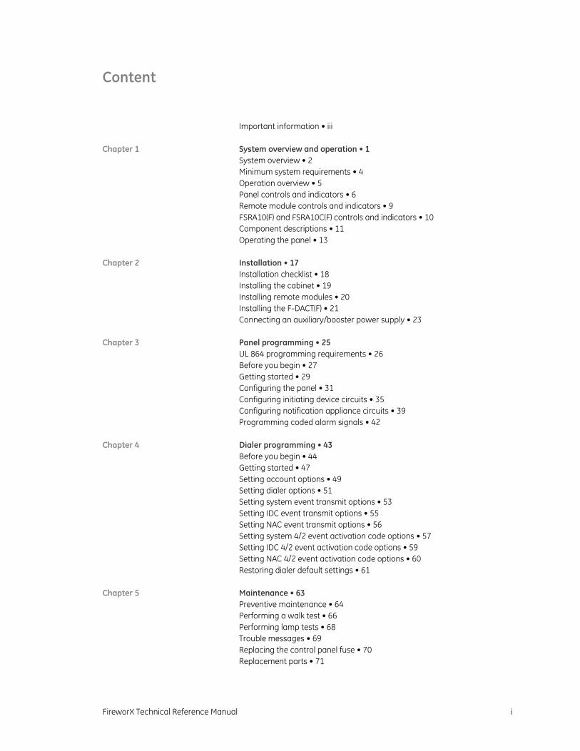
Content
Important information • iii
Chapter 1 System overview and operation • 1 System overview • 2 Minimum system requirements • 4 Operation overview • 5 Panel controls and indicators • 6 Remote module controls and indicators • 9 FSRA10(F) and FSRA10C(F) controls and indicators • 10 Component descriptions • 11 Operating the panel • 13
Chapter 2 Installation • 17 Installation checklist • 18 Installing the cabinet • 19 Installing remote modules • 20 Installing the F-DACT(F) • 21 Connecting an auxiliary/booster power supply • 23
Chapter 3 Panel programming • 25 UL 864 programming requirements • 26 Before you begin • 27 Getting started • 29 Configuring the panel • 31 Configuring initiating device circuits • 35 Configuring notification appliance circuits • 39 Programming coded alarm signals • 42
Chapter 4 Dialer programming • 43 Before you begin • 44 Getting started • 47 Setting account options • 49 Setting dialer options • 51 Setting system event transmit options • 53 Setting IDC event transmit options • 55 Setting NAC event transmit options • 56 Setting system 4/2 event activation code options • 57 Setting IDC 4/2 event activation code options • 59 Setting NAC 4/2 event activation code options • 60 Restoring dialer default settings • 61
Chapter 5 Maintenance • 63 Preventive maintenance • 64 Performing a walk test • 66 Performing lamp tests • 68 Trouble messages • 69 Replacing the control panel fuse • 70 Replacement parts • 71
ii FireworX Technical Reference Manual
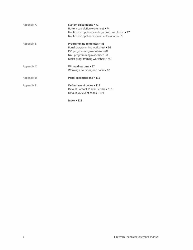
Appendix A System calculations • 73 Battery calculation worksheet • 74 Notification appliance voltage drop calculation • 77 Notification appliance circuit calculations • 79
Appendix B Programming templates • 85 Panel programming worksheet • 86 IDC programming worksheet • 87 NAC programming worksheet • 89 Dialer programming worksheet • 90
Appendix C Wiring diagrams • 97 Warnings, cautions, and notes • 98
Appendix D Panel specifications • 115
Appendix E Default event codes • 117 Default Contact ID event codes • 118 Default 4/2 event codes • 119
Index • 121
FireworX Technical Reference Manual iii
Important information
Limitation of liability
This product has been designed to meet the requirements of NFPA 72 National Fire Alarm Code, UL 864 Standard for Control Units and Accessories for Fire Alarm Systems, and ULC S527 Standard for Control Units for Fire Alarm Systems. Installation in accordance with this manual, applicable codes, and the instructions of the authority having jurisdiction is mandatory. GE Security shall not under any circumstances be liable for any incidental or consequential damages arising from loss of property or other damages or losses owing to the failure of GE Security products beyond the cost of repair or replacement of any defective products. GE Security reserves the right to make product improvements and change product specifications at any time.
While every precaution has been taken during the preparation of this manual to ensure the accuracy of its contents, GE Security assumes no responsibility for errors or omissions.
FCC warning This equipment can generate and radiate radio frequency energy. If this equipment is not installed in accordance with this manual, it may cause interference to radio communications. This equipment has been tested and found to comply with the limits for Class A computing devices pursuant to Subpart B of Part 15 of the FCC Rules. These rules are designed to provide reasonable protection against such interference when this equipment is operated in a commercial environment. Operation of this equipment is likely to cause interference, in which case the user at his own expense, will be required to take whatever measures may be required to correct the interference.
F-DACT(F) FCC information
Cautions
To ensure proper operation, this dialer must be installed according to the enclosed installation instructions. To verify that the dialer is operating properly and can successfully report an alarm, it must be tested immediately after installation, and periodically thereafter, according to the enclosed test instructions.
In order for the dialer to be able to seize the phone line to report an alarm or other event when other customer equipment (telephone, answering system, computer modem, etc.) connected to the same line is in use, the dialer must be connected to a properly installed RJ-31X jack. The RJ-31X jack must be connected in series with, and ahead of, all other equipment attached to the same phone line.
iv FireworX Technical Reference Manual
Series installation of an RJ-31X jack is depicted in the wiring diagram. If you have any questions concerning these instructions, you should consult your telephone company or a qualified installer.
Testing
When programming emergency numbers or making test calls to emergency numbers, remain on the line and briefly explain to the dispatcher the reason for the call. Perform programming and testing activities in the off-peak hours, such as early morning or late evenings.
Compliance requirements
For equipment approved before July 23, 2001: This dialer complies with Part 68 of the FCC rules. A label attached to the dialer contains, among other information, the FCC registration number and ringer equivalence number (REN) for this equipment. If requested, this information must be provided to the telephone company.
For equipment approved after July 23, 2001: This dialer complies with Part 68 of the FCC rules and the requirements adopted by the Administrative Council for Terminal Attachments (ACTA). A label attached to the dialer contains, among other information, a product identifier in the format US:AAAEQ##TXXXX. If requested, this information must be provided to the telephone company.
The plug and jack used to connect the dialer to the premises wiring and telephone network must comply with the applicable FCC Part 68 rules and requirements adopted by ACTA. The dialer must be connected to a compliant RJ-31X or RJ-38X jack using a compliant cord. If a modular telephone cord is supplied with the dialer, it is designed to meet these requirements. See installation instructions for details.
A ringer equivalence number (REN) is used to determine how many devices you can connect to a telephone line. If the total REN value for all devices connected on a telephone line exceeds that allowed by the telephone company, the devices may not ring on an incoming call. In most (but not all) areas the total REN value should not exceed 5.0. To be certain of the total REN value allowed on a telephone line, contact the local telephone company.
For products approved after July 23, 2001, the REN is part of the product identifier in the format US:AAAEQ##TXXXX. The digits ## represent the REN without a decimal point. Example: 03 is an REN of 0.3. For earlier products the REN is listed separately.
If the dialer is harming the telephone network, the telephone company will notify you in advance that temporary discontinuance of service may be required. If advance notice isn’t practical, the telephone company will notify you as soon as possible. You will also be advised of your right to file a complaint with the FCC, if you believe it is necessary.

FireworX Technical Reference Manual v
The telephone company may make changes to its facilities, equipment, operations, or procedures that could affect the operation of the dialer. If this happens, the telephone company will provide advance notice in order for you to make necessary modifications to maintain uninterrupted service.
If you are experiencing problems with the dialer, contact GE Technical Support at 1-800-655-4497 for repair or warranty information. If the dialer is harming the telephone network, the telephone company may request that you disconnect the dialer until the problem is resolved.
The dialer contains no user serviceable parts. In case of defects, return the dialer for repair.
You may not connect the dialer to a public coin phone or a party line service provided by the telephone company.
Industry Canada information
The Industry Canada label identifies certified equipment. This certification means that the equipment meets certain telecommunications network protective, operational, and safety requirements. Industry Canada does not guarantee the equipment will operate to the user’s satisfaction.
Before installing this equipment, users should ensure that it is permissible to be connected to the facilities of the local telecommunications company. The equipment must also be installed using an acceptable method of connection. The customer should be aware that compliance with the above conditions may not prevent degradation of service in some situations.
Repairs to certified equipment should be made by an authorized Canadian maintenance facility designated by the supplier. Any repairs or alterations made by the user to this equipment, or equipment malfunctions, may give the telecommunications company cause to request the user disconnect the equipment.
Users should ensure for their own protection that the electrical ground connections of the power utility, telephone lines, and internal metallic water pipe system, if present, are connected together. This precaution may be particularly important in rural areas.
The Load Number (LN) assigned to each terminal device denotes the percentage of the total load to be connected to a telephone loop which is used by the device, to prevent overloading. The termination on a loop may consist of any combination of devices subject only to the requirements that the sum of the Load Numbers of all the devices does not exceed 100.
Caution: Users should not attempt to make such connections themselves, but should contact the appropriate electric inspection authority, or electrician, as appropriate

vi FireworX Technical Reference Manual
FireworX Technical Reference Manual 1
Chapter 1 System overview and operation
Summary
This chapter provides an overview of the panel and major system components. It describes the controls and indicators located on the panel and components. In addition, detailed instructions are given for operating the panel.
Content
System overview • 2 Minimum system requirements • 4 Operation overview • 5 Panel controls and indicators • 6 Remote module controls and indicators • 9 FSRA10(F) and FSRA10C(F) controls and indicators • 10 Component descriptions • 11 Operating the panel • 13
Resetting the panel • 13 Silencing the panel and FSRSI buzzers • 13 Silencing notification appliances • 14 Resounding an alarm condition • 14 Disabling an IDC • 15 Disabling an NAC • 15 Enabling a disabled IDC or NAC • 15 Using the drill command • 16
Chapter 1: System overview and operation
2 FireworX Technical Reference Manual
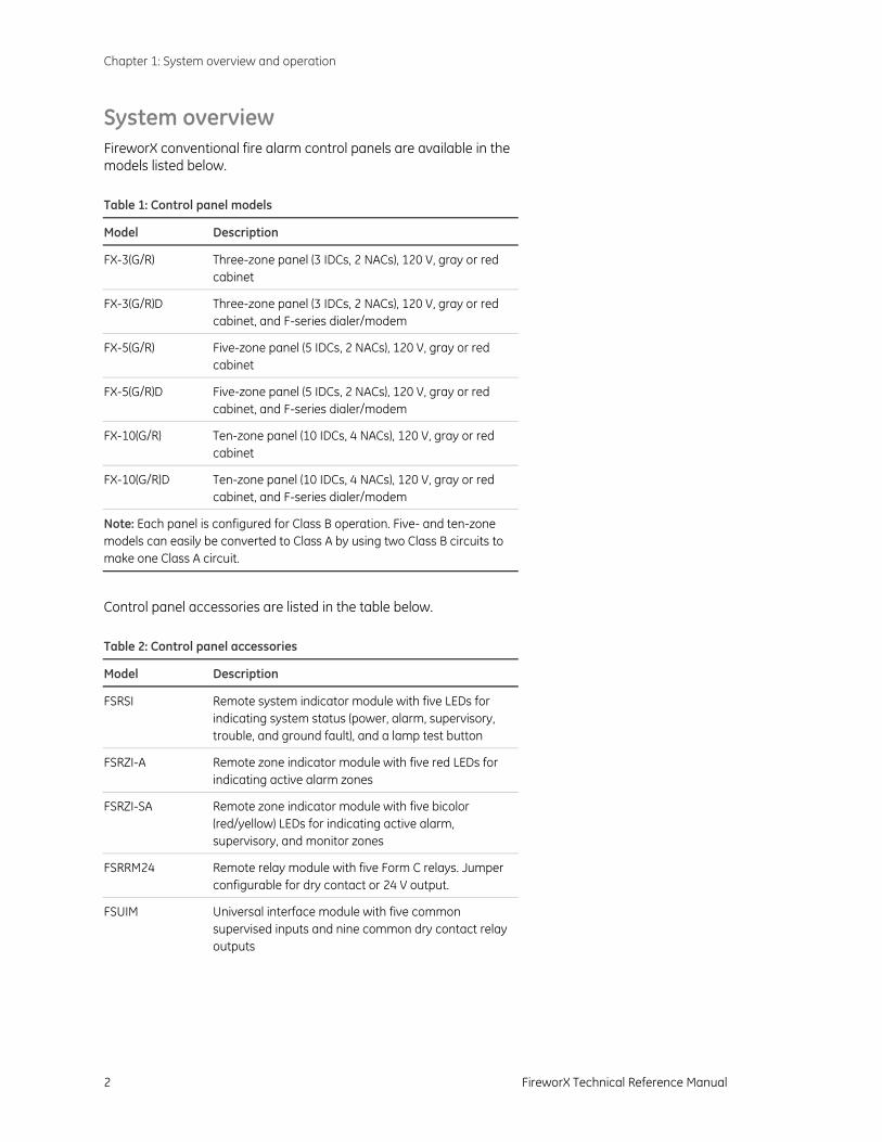
System overview FireworX conventional fire alarm control panels are available in the models listed below. Table 1: Control panel models
Model Description
FX-3(G/R) Three-zone panel (3 IDCs, 2 NACs), 120 V, gray or red cabinet
FX-3(G/R)D Three-zone panel (3 IDCs, 2 NACs), 120 V, gray or red cabinet, and F-series dialer/modem
FX-5(G/R) Five-zone panel (5 IDCs, 2 NACs), 120 V, gray or red cabinet
FX-5(G/R)D Five-zone panel (5 IDCs, 2 NACs), 120 V, gray or red cabinet, and F-series dialer/modem
FX-10(G/R) Ten-zone panel (10 IDCs, 4 NACs), 120 V, gray or red cabinet
FX-10(G/R)D Ten-zone panel (10 IDCs, 4 NACs), 120 V, gray or red cabinet, and F-series dialer/modem
Note: Each panel is configured for Class B operation. Five- and ten-zone models can easily be converted to Class A by using two Class B circuits to make one Class A circuit.
Control panel accessories are listed in the table below. Table 2: Control panel accessories
Model Description
FSRSI Remote system indicator module with five LEDs for indicating system status (power, alarm, supervisory, trouble, and ground fault), and a lamp test button
FSRZI-A Remote zone indicator module with five red LEDs for indicating active alarm zones
FSRZI-SA Remote zone indicator module with five bicolor (red/yellow) LEDs for indicating active alarm, supervisory, and monitor zones
FSRRM24 Remote relay module with five Form C relays. Jumper configurable for dry contact or 24 V output.
FSUIM Universal interface module with five common supervised inputs and nine common dry contact relay outputs
Chapter 1: System overview and operation
FireworX Technical Reference Manual 3
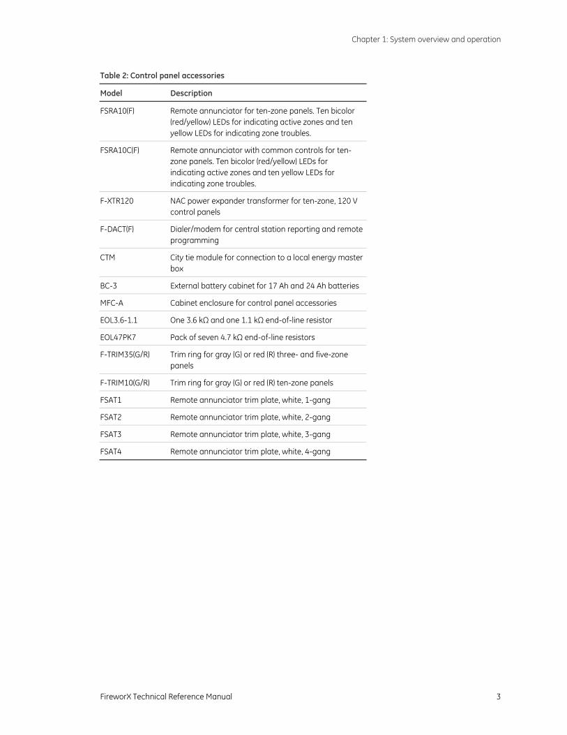
Table 2: Control panel accessories
Model Description
FSRA10(F) Remote annunciator for ten-zone panels. Ten bicolor (red/yellow) LEDs for indicating active zones and ten yellow LEDs for indicating zone troubles.
FSRA10C(F) Remote annunciator with common controls for ten-zone panels. Ten bicolor (red/yellow) LEDs for indicating active zones and ten yellow LEDs for indicating zone troubles.
F-XTR120 NAC power expander transformer for ten-zone, 120 V control panels
F-DACT(F) Dialer/modem for central station reporting and remote programming
CTM City tie module for connection to a local energy master box
BC-3 External battery cabinet for 17 Ah and 24 Ah batteries
MFC-A Cabinet enclosure for control panel accessories
EOL3.6-1.1 One 3.6 kΩ and one 1.1 kΩ end-of-line resistor
EOL47PK7 Pack of seven 4.7 kΩ end-of-line resistors
F-TRIM35(G/R) Trim ring for gray (G) or red (R) three- and five-zone panels
F-TRIM10(G/R) Trim ring for gray (G) or red (R) ten-zone panels
FSAT1 Remote annunciator trim plate, white, 1-gang
FSAT2 Remote annunciator trim plate, white, 2-gang
FSAT3 Remote annunciator trim plate, white, 3-gang
FSAT4 Remote annunciator trim plate, white, 4-gang
Chapter 1: System overview and operation
4 FireworX Technical Reference Manual
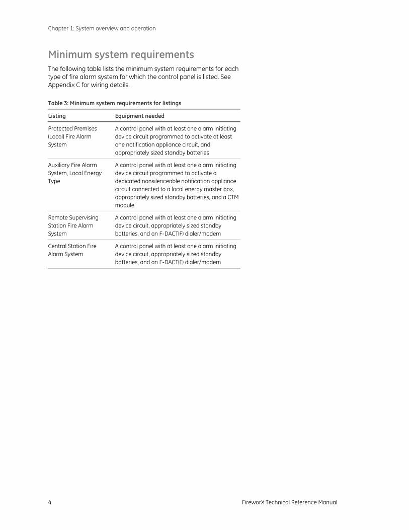
Minimum system requirements The following table lists the minimum system requirements for each type of fire alarm system for which the control panel is listed. See Appendix C for wiring details. Table 3: Minimum system requirements for listings
Listing Equipment needed
Protected Premises (Local) Fire Alarm System
A control panel with at least one alarm initiating device circuit programmed to activate at least one notification appliance circuit, and appropriately sized standby batteries
Auxiliary Fire Alarm System, Local Energy Type
A control panel with at least one alarm initiating device circuit programmed to activate a dedicated nonsilenceable notification appliance circuit connected to a local energy master box, appropriately sized standby batteries, and a CTM module
Remote Supervising Station Fire Alarm System
A control panel with at least one alarm initiating device circuit, appropriately sized standby batteries, and an F-DACT(F) dialer/modem
Central Station Fire Alarm System
A control panel with at least one alarm initiating device circuit, appropriately sized standby batteries, and an F-DACT(F) dialer/modem
Chapter 1: System overview and operation
FireworX Technical Reference Manual 5
Operation overview The panel operates in normal mode in the absence of any alarm, supervisory, trouble, or monitor events. In normal mode, the control panel monitors the system.
The panel operates in off-normal mode any time an event is introduced into the system. When this happens, the panel:
• Changes contact positions on appropriate common relays
• Activates alarm outputs (for alarm events only)
• Turns on the appropriate LEDs and the panel buzzer
• Executes the appropriate programmed output response for the input that activated the event
• Communicates event information to appropriate optional components
If a dialer is installed, the panel:
• Sends a record of the event to the F-DACT(F) LCD and to the history log
• Transmits event activation and restoration codes to a monitoring station as programmed
Chapter 1: System overview and operation
6 FireworX Technical Reference Manual
Panel controls and indicators
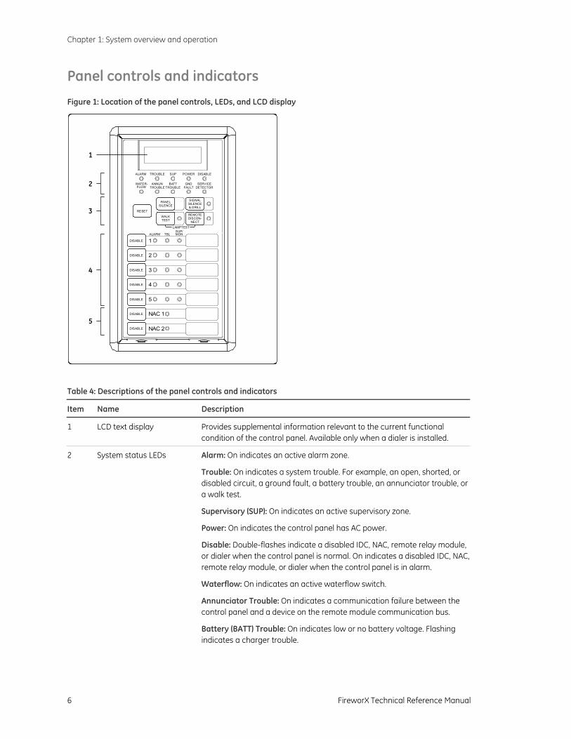
Figure 1: Location of the panel controls, LEDs, and LCD display
ALARM TBLSUP/MON
RESET
1
DISABLE 3
DISABLE 5
DISABLE NAC 1
DISABLE NAC 2
DISABLE 2
DISABLE 4
DISABLE
WALKTEST
SIGNALSILENCE& DRILL
REMOTEDISCON-
NECT
PANELSILENCE
ALARM TROUBLE SUP POWER DISABLE
WATER-FLOW
ANNUNTROUBLE
BATTTROUBLE
GNDFAULT
SERVICEDETECTOR
LAMPTEST
1
2
3
5
4
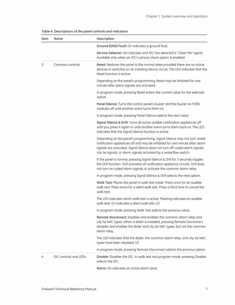
Table 4: Descriptions of the panel controls and indicators
Item Name Description
1 LCD text display Provides supplemental information relevant to the current functional condition of the control panel. Available only when a dialer is installed.
2 System status LEDs Alarm: On indicates an active alarm zone.
Trouble: On indicates a system trouble. For example, an open, shorted, or disabled circuit, a ground fault, a battery trouble, an annunciator trouble, or a walk test.
Supervisory (SUP): On indicates an active supervisory zone.
Power: On indicates the control panel has AC power.
Disable: Double-flashes indicate a disabled IDC, NAC, remote relay module, or dialer when the control panel is normal. On indicates a disabled IDC, NAC,remote relay module, or dialer when the control panel is in alarm.
Waterflow: On indicates an active waterflow switch.
Annunciator Trouble: On indicates a communication failure between the control panel and a device on the remote module communication bus.
Battery (BATT) Trouble: On indicates low or no battery voltage. Flashing indicates a charger trouble.
Chapter 1: System overview and operation
FireworX Technical Reference Manual 7
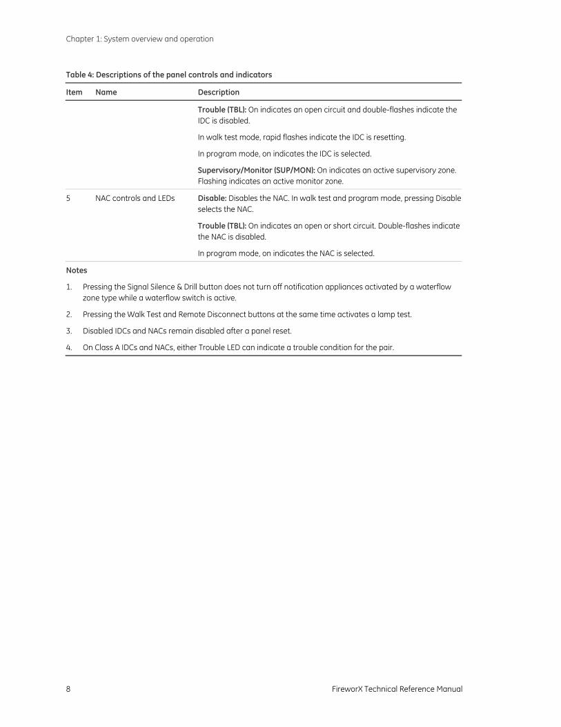
Table 4: Descriptions of the panel controls and indicators
Item Name Description
Ground (GND) Fault: On indicates a ground fault.
Service Detector: On indicates and IDC has detected a “Clean Me” signal. Available only when an IDC’s service check option is enabled.
3 Common controls Reset: Restores the panel to the normal state provided there are no active devices or switches on an initiating device circuit. The LED indicates that the Reset function is active.
Depending on the panel’s programming, Reset may be inhibited for one minute after alarm signals are activated.
In program mode, pressing Reset enters the current value for the selected option.
Panel Silence: Turns the control panel’s buzzer and the buzzer on FSRSI modules off until another event turns them on.
In program mode, pressing Panel Silence selects the next value.
Signal Silence & Drill: Turns all active audible notification appliances off until you press it again or until another event turns them back on. The LED indicates that the Signal Silence function is active.
Depending on the panel’s programming, Signal Silence may not turn visible notification appliances off and may be inhibited for one minute after alarm signals are activated. Signal Silence does not turn off coded alarm signals, city tie signals, or alarm signals activated by a waterflow switch.
If the panel is normal, pressing Signal Silence & Drill for 2 seconds toggles the Drill function. Drill activates all notification appliance circuits. Drill does not turn on coded alarm signals or activate the common alarm relay.
In program mode, pressing Signal Silence & Drill selects the next option.
Walk Test: Places the panel in walk test mode. Press once for an audible walk test. Press twice for a silent walk test. Press a third time to cancel the walk test.
The LED indicates which walk test is active. Flashing indicates an audible walk test. On indicates a silent walk test. [2]
In program mode, pressing Walk Test selects the previous value.
Remote Disconnect: Disables and enables the common alarm relay and city tie NAC types. When a dialer is installed, pressing Remote Disconnect disables and enables the dialer and city tie NAC types, but not the common alarm relay.
The LED indicates that the dialer, the common alarm relay, and city tie NAC types have been disabled. [2]
In program mode, pressing Remote Disconnect selects the previous option.
4 IDC controls and LEDs Disable: Disables the IDC. In walk test and program mode, pressing Disable selects the IDC.
Alarm: On indicates an active alarm zone.
Chapter 1: System overview and operation
8 FireworX Technical Reference Manual
Table 4: Descriptions of the panel controls and indicators
Item Name Description
Trouble (TBL): On indicates an open circuit and double-flashes indicate the IDC is disabled.
In walk test mode, rapid flashes indicate the IDC is resetting.
In program mode, on indicates the IDC is selected.
Supervisory/Monitor (SUP/MON): On indicates an active supervisory zone. Flashing indicates an active monitor zone.
5 NAC controls and LEDs Disable: Disables the NAC. In walk test and program mode, pressing Disableselects the NAC.
Trouble (TBL): On indicates an open or short circuit. Double-flashes indicate the NAC is disabled.
In program mode, on indicates the NAC is selected.
Notes
1. Pressing the Signal Silence & Drill button does not turn off notification appliances activated by a waterflow zone type while a waterflow switch is active.
2. Pressing the Walk Test and Remote Disconnect buttons at the same time activates a lamp test.
3. Disabled IDCs and NACs remain disabled after a panel reset.
4. On Class A IDCs and NACs, either Trouble LED can indicate a trouble condition for the pair.
Chapter 1: System overview and operation
FireworX Technical Reference Manual 9
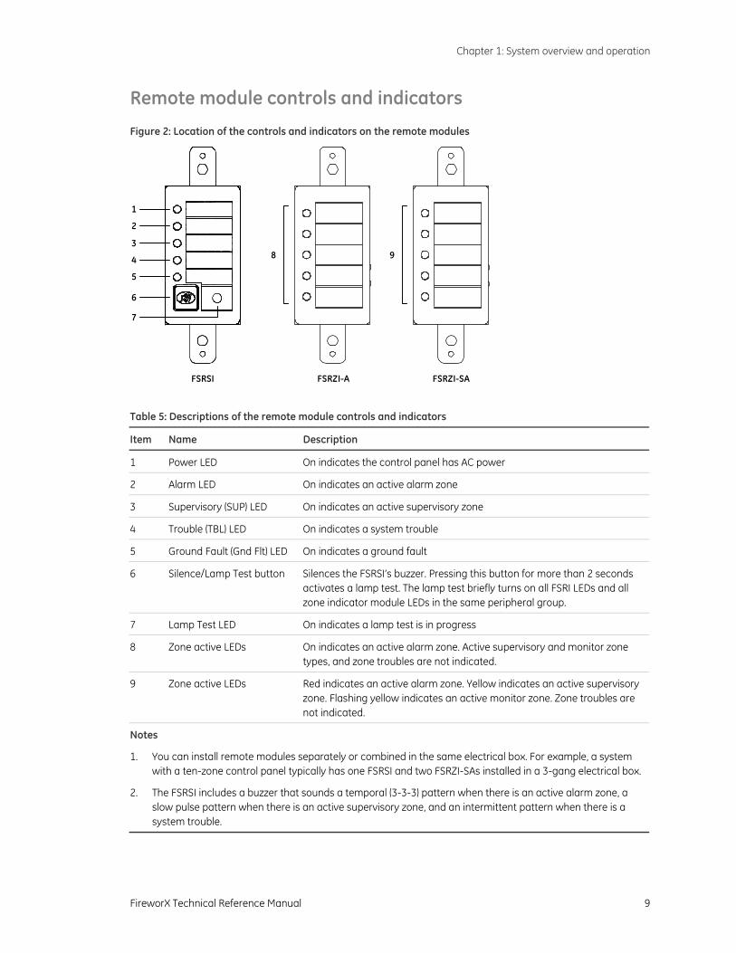
Remote module controls and indicators
Figure 2: Location of the controls and indicators on the remote modules
1
FSRSI
2
3
4
5
6
7
FSRZI-A
8
FSRZI-SA
9
Table 5: Descriptions of the remote module controls and indicators
Item Name Description
1 Power LED On indicates the control panel has AC power
2 Alarm LED On indicates an active alarm zone
3 Supervisory (SUP) LED On indicates an active supervisory zone
4 Trouble (TBL) LED On indicates a system trouble
5 Ground Fault (Gnd Flt) LED On indicates a ground fault
6 Silence/Lamp Test button Silences the FSRSI’s buzzer. Pressing this button for more than 2 seconds activates a lamp test. The lamp test briefly turns on all FSRI LEDs and all zone indicator module LEDs in the same peripheral group.
7 Lamp Test LED On indicates a lamp test is in progress
8 Zone active LEDs On indicates an active alarm zone. Active supervisory and monitor zone types, and zone troubles are not indicated.
9 Zone active LEDs Red indicates an active alarm zone. Yellow indicates an active supervisory zone. Flashing yellow indicates an active monitor zone. Zone troubles are not indicated.
Notes
1. You can install remote modules separately or combined in the same electrical box. For example, a system with a ten-zone control panel typically has one FSRSI and two FSRZI-SAs installed in a 3-gang electrical box.
2. The FSRSI includes a buzzer that sounds a temporal (3-3-3) pattern when there is an active alarm zone, a slow pulse pattern when there is an active supervisory zone, and an intermittent pattern when there is a system trouble.
Chapter 1: System overview and operation
10 FireworX Technical Reference Manual
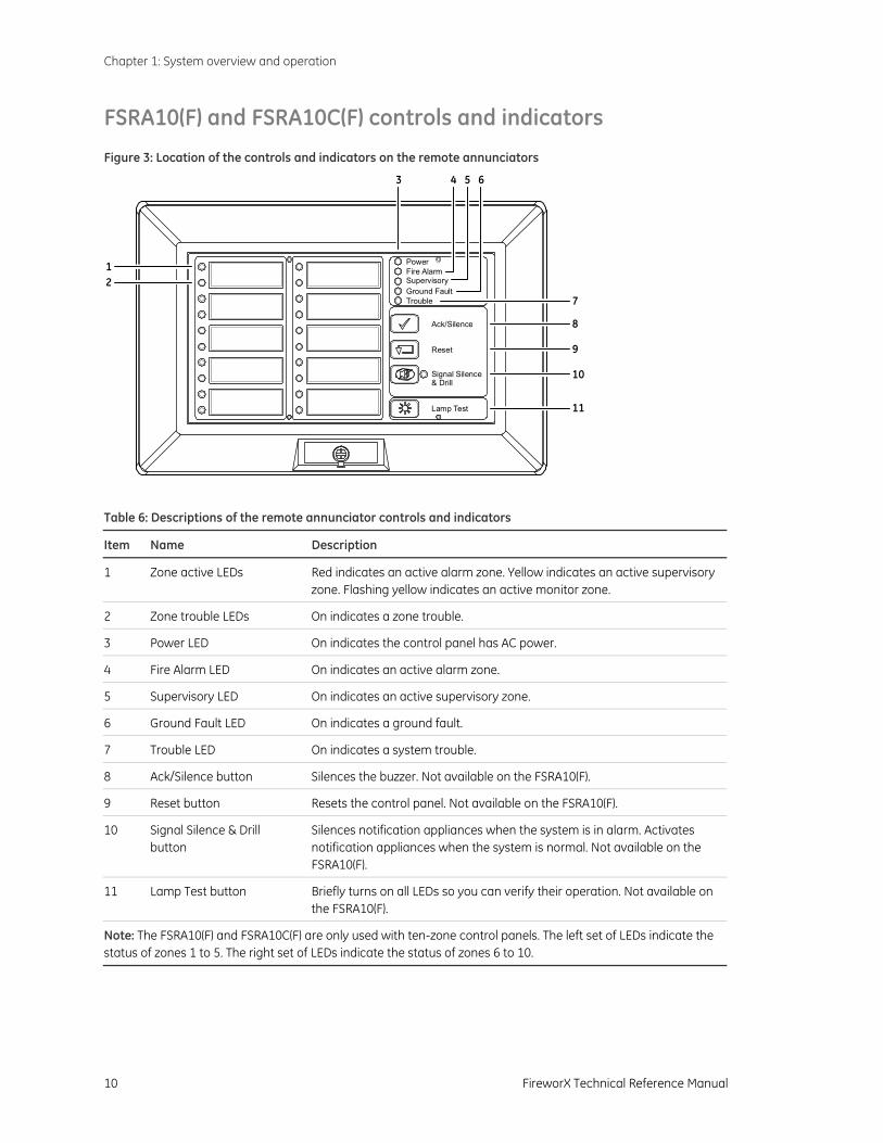
FSRA10(F) and FSRA10C(F) controls and indicators
Figure 3: Location of the controls and indicators on the remote annunciators
Lamp Test
PowerFire AlarmSupervisoryGround FaultTrouble
Signal Silence& Drill
Reset
Ack/Silence
12
3 4 5 6
8
9
10
11
7
Table 6: Descriptions of the remote annunciator controls and indicators
Item Name Description
1 Zone active LEDs Red indicates an active alarm zone. Yellow indicates an active supervisory zone. Flashing yellow indicates an active monitor zone.
2 Zone trouble LEDs On indicates a zone trouble.
3 Power LED On indicates the control panel has AC power.
4 Fire Alarm LED On indicates an active alarm zone.
5 Supervisory LED On indicates an active supervisory zone.
6 Ground Fault LED On indicates a ground fault.
7 Trouble LED On indicates a system trouble.
8 Ack/Silence button Silences the buzzer. Not available on the FSRA10(F).
9 Reset button Resets the control panel. Not available on the FSRA10(F).
10 Signal Silence & Drill button
Silences notification appliances when the system is in alarm. Activates notification appliances when the system is normal. Not available on the FSRA10(F).
11 Lamp Test button Briefly turns on all LEDs so you can verify their operation. Not available on the FSRA10(F).
Note: The FSRA10(F) and FSRA10C(F) are only used with ten-zone control panels. The left set of LEDs indicate the status of zones 1 to 5. The right set of LEDs indicate the status of zones 6 to 10.
Chapter 1: System overview and operation
FireworX Technical Reference Manual 11
Component descriptions
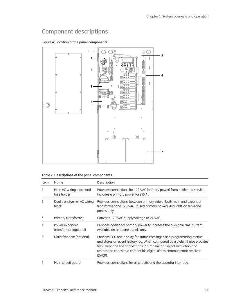
Figure 4: Location of the panel components
1
2
3
4
5
6
7
Table 7: Descriptions of the panel components
Item Name Description
1 Main AC wiring block and fuse holder
Provides connections for 120 VAC (primary power) from dedicated service. Includes a primary power fuse (5 A).
2 Dual transformer AC wiring block
Provides connections between primary side of both main and expander transformer and 120 VAC (fused primary power). Available on ten-zone panels only.
3 Primary transformer Converts 120 VAC supply voltage to 24 VAC.
4 Power expander transformer (optional)
Provides additional primary power to increase the available NAC current. Available on ten-zone panels only.
5 Dialer/modem (optional) Provides LCD text display for status messages and programming menus, and stores an event history log. When configured as a dialer, it also providestwo telephone line connections for transmitting event activation and restoration codes to a compatible digital alarm communicator receiver (DACR).
6 Main circuit board Provides connections for all circuits and the operator interface.
Chapter 1: System overview and operation
12 FireworX Technical Reference Manual
Table 7: Descriptions of the panel components
Item Name Description
7 Standby batteries Provide secondary (standby) power in the absence of primary power. We recommend using the following:
For 3- and 5-zone control units: GE Security models 12V4A or 12V6A5, or equivalent
For 10-zone control units: GE Security models 12V4A, 12V6A5, or 12V10A, or equivalent
Larger batteries must be installed in a BC-3 battery cabinet.
Chapter 1: System overview and operation
FireworX Technical Reference Manual 13
Operating the panel
Resetting the panel
Pressing Reset restores the control panel to the normal state provided there are no active devices on a circuit. When you reset the panel:
• All LEDs on the panel turn on for five seconds
• The trouble and power LEDs remain on for an additional 15 seconds
• When reset is complete, the buzzer sounds (then turns off) and the trouble LED turns off
While the control panel is resetting:
• All panel indicators are temporarily cleared
• All notification appliances are turned off
• All latched IDCs are cleared
• Alarm, trouble, and supervisory relays are returned to the inactive state
• Resettable auxiliary power momentarily turns off
At the conclusion of the reset, if an IDC is in an off-normal state, the panel treats the event as a new event and activates the programmed responses. Pressing Disable for the active IDC within 30 seconds after the panel has reset turns off the NACs and disables the IDC.
If one or more IDCs are disabled prior to initiation of the reset, those IDCs remain disabled.
If signal silence inhibit or reset inhibit is enabled, system reset is inhibited during the silence or reset inhibit period.
To reset the panel:
1. Press the Reset button.
Silencing the panel and FSRSI buzzers Both the panel and the optional FSRSI module have buzzer silence buttons. Pressing the Panel Silence button silences the buzzer on the panel and on remote FSRSIs.
Pressing the FSRSI Silence button silences the buzzer on the FSRSI only.
WARNING: Notification appliances should not be silenced until the building is fully evacuated and the cause of the alarm has been determined.
Chapter 1: System overview and operation
14 FireworX Technical Reference Manual
To silence the panel buzzer:
1. Press the Panel Silence button on the panel.
2. Determine the type of condition that caused the buzzer to sound: alarm, trouble, supervisory, or monitor.
3. Determine the cause of the condition.
To silence the FSRSI buzzer:
1. Press the Silence button on the FSRSI.
2. Determine the type of condition that caused the buzzer to sound: alarm, trouble, supervisory, or monitor.
3. Determine the cause of the condition.
Silencing notification appliances
Pressing the Signal Silence & Drill button turns off all audible notification appliances. Visible notification appliances or NAC circuits may or may not turn off, depending on panel programming.
When you silence the signals, the Signal Silenced LED turns on, indicating that the notification appliances are off. The panel does not indicate a trouble condition. If Genesis, horn/strobe, or horn-only devices are used on NACs programmed for Genesis operation, Signal Silence & Drill silences only the horns.
To silence notification appliances:
1. Press the Signal Silence & Drill button.
When the auto signal silence timer is programmed
When an event activates the notification appliances, the auto signal silence timer is activated. The notification appliances are activated for the time period defined during programming. When the timer expires, any NACs that are programmed as silenceable are deactivated, and the Signal Silenced LED turns on.
If another event takes place that activates the previously silenced notification appliances, the Signal Silenced LED turns off. At any time, you can deactivate silenceable NACs by pressing Signal Silence & Drill.
Resounding an alarm condition Pressing the Signal Silence & Drill button again turns the audible devices back on if they were silenced.
To resound notification appliances:
1. Press the Signal Silence & Drill button.
WARNING: Notification appliances should not be silenced until the building is fully evacuated and the cause of the alarm has been determined.
Note: NACs activated by IDCs programmed as waterflow cannot be silenced until the activated devices are restored to normal. After the devices restore, the Signal Silence & Drill button or the auto signal silence timer can silence the NACs.
Note: NACs resound automatically if a new alarm (from another IDC) is received.
Chapter 1: System overview and operation
FireworX Technical Reference Manual 15
Disabling an IDC
Pressing an IDC Disable button prevents the panel from responding to any status change from that IDC. When you disable an IDC:
• The common Disable LED double-flashes
• The IDC Trouble LED double-flashes
• The common Trouble LED turns on and the panel goes into the trouble state
• The common trouble relay changes state
Resetting the panel has no effect on a disabled IDC, but removing all power from the panel clears the disable and enables the IDC.
To disable an IDC:
1. Press the Disable button for the IDC you want to disable.
Disabling an NAC
When you disable an NAC:
• The common Disable LED double-flashes
• The NAC Trouble LED double-flashes
• The common Trouble LED turns on and the panel goes into a trouble state
• The common trouble relay changes state
Resetting the panel has no effect on a disabled NAC, but removing all power from the panel clears the disable and enables the NAC.
To disable an NAC:
1. Press the Disable button for the NAC that you want to disable.
Enabling a disabled IDC or NAC When you enable a disabled IDC or NAC:
• The common Disable LED turns off
• The IDC or NAC trouble LED turns off
• The common Trouble LED turns off and the panel returns to normal
• The IDC or NAC LEDs are updated to show current status
Example: If the IDC or NAC is in trouble, the Trouble LED turns on.
After enabling an IDC, alarms from that IDC are inhibited for 30 seconds. During this time, the IDC can be disabled to avoid an unwanted alarm.
Note: During an alarm condition, all flashing LEDs go steady.
Chapter 1: System overview and operation
16 FireworX Technical Reference Manual
To enable a disabled IDC or NAC:
1. Press the Disable button for the IDC or NAC you want to enable.
Using the drill command
You can use the drill command to activate all of the notification appliance circuits. Pressing Drill activates all audibles and visibles according to the panel programming, but does not activate the panel’s common alarm relay. The F-DACT(F) can be programmed to transmit a drill condition, but it will never report the drill as an alarm. Drill will not operate with an active alarm or supervisory event at the panel.
To perform a fire drill:
1. Press and hold the Signal Silence & Drill button for one second.
2. To stop the drill, press and hold the Signal Silence & Drill button for one second.
FireworX Technical Reference Manual 17
Chapter 2 Installation
Summary
This chapter provides instructions for installing the fire alarm system. It is intended for trained installers who are familiar with all applicable codes and regulations.
Content
Installation checklist • 18 Installing the cabinet • 19 Installing remote modules • 20 Installing the F-DACT(F) • 21
NFPA 72 compliance requirements • 21 Receiver compatibility • 22
Connecting an auxiliary/booster power supply • 23
Chapter 2: Installation
18 FireworX Technical Reference Manual
Installation checklist
Prepare the site. Make sure the installation location is free from construction dust and debris and extreme temperature ranges and humidity.
Unpack the equipment.
Install the cabinet. See “Installing the cabinet“ on page 19 for cabinet dimensions.
Remove the clear protective plastic from the front panel display.
Install the F-DACT(F), if required. For more information, see "Installing the F-DACT(F)" on page 21.
Connect the field wiring. For details, see Appendix C “Wiring diagrams“ on page 97 or the panel door label.
Meter for opens, grounds, and shorts before connecting wires.
For more information on remote modules, see “Installing remote modules“ on page 20.
Connect AC power and ground. For wiring diagrams, see Appendix C or the panel label.
Connect the batteries. For wiring diagrams, see Appendix C or the panel door label.
Program the panel. See Chapter 3 “Panel programming“ on page 25.
Program the dialer, if installed. See Chapter 4 “Dialer programming“ on page 43.
Test the system for proper operation.
WARNING: Make sure that the AC power circuit breaker is off before connecting wires to the terminal block.
Note: The panel will not turn on if AC power is not applied.
Chapter 2: Installation
FireworX Technical Reference Manual 19
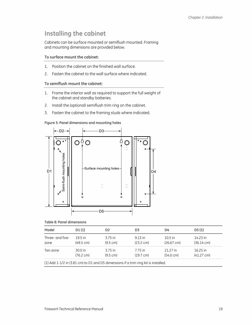
Installing the cabinet Cabinets can be surface mounted or semiflush mounted. Framing and mounting dimensions are provided below.
To surface mount the cabinet:
1. Position the cabinet on the finished wall surface.
2. Fasten the cabinet to the wall surface where indicated.
To semiflush mount the cabinet:
1. Frame the interior wall as required to support the full weight of the cabinet and standby batteries.
2. Install the (optional) semiflush trim ring on the cabinet.
3. Fasten the cabinet to the framing studs where indicated.
Figure 5: Panel dimensions and mounting holes
D1
D2 D3
D4
D5
Surface mounting holes
Sem
i-flu
sh m
ount
ing
hole
s
Table 8: Panel dimensions
Model D1 [1] D2 D3 D4 D5 [1]
Three- and five- zone
19.5 in (49.5 cm)
3.75 in (9.5 cm)
9.13 in (23.2 cm)
10.5 in (26.67 cm)
14.23 in (36.14 cm)
Ten-zone 30.0 in (76.2 cm)
3.75 in (9.5 cm)
7.75 in (19.7 cm)
21.27 in (54.0 cm)
16.25 in (41.27 cm)
[1] Add 1-1/2 in (3.81 cm) to D1 and D5 dimensions if a trim ring kit is installed.
Chapter 2: Installation
20 FireworX Technical Reference Manual
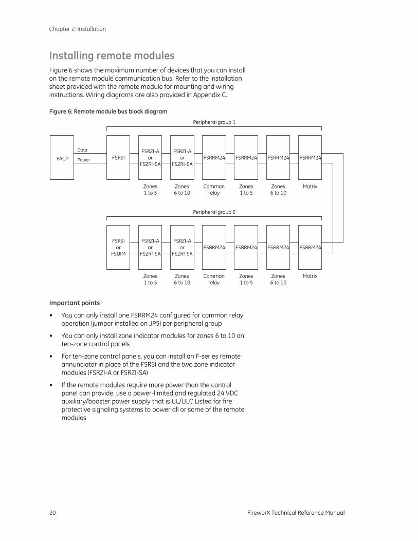
Installing remote modules Figure 6 shows the maximum number of devices that you can install on the remote module communication bus. Refer to the installation sheet provided with the remote module for mounting and wiring instructions. Wiring diagrams are also provided in Appendix C.
Figure 6: Remote module bus block diagram
Power
Data
FSRSIFSRZI-A
orFSZRI-SA
FSRRM24 FSRRM24 FSRRM24 FSRRM24FACP
Peripheral group 1
Zones1 to 5
FSRZI-Aor
FSZRI-SA
Zones6 to 10
Commonrelay
Zones1 to 5
Zones6 to 10
Matrix
FSRSIor
FSUIM
FSRZI-Aor
FSZRI-SAFSRRM24 FSRRM24 FSRRM24 FSRRM24
Peripheral group 2
Zones1 to 5
FSRZI-Aor
FSZRI-SA
Zones6 to 10
Commonrelay
Zones1 to 5
Zones6 to 10
Matrix
Important points
• You can only install one FSRRM24 configured for common relay operation (jumper installed on JP5) per peripheral group
• You can only install zone indicator modules for zones 6 to 10 on ten-zone control panels
• For ten-zone control panels, you can install an F-series remote annunciator in place of the FSRSI and the two zone indicator modules (FSRZI-A or FSRZI-SA)
• If the remote modules require more power than the control panel can provide, use a power-limited and regulated 24 VDC auxiliary/booster power supply that is UL/ULC Listed for fire protective signaling systems to power all or some of the remote modules
Chapter 2: Installation
FireworX Technical Reference Manual 21
Installing the F-DACT(F) The F-DACT(F), also called the dialer, is a digital alarm communicator transmitter (DACT). The dialer transmits event activation and restoration codes to a compatible digital alarm communicator receiver (DACR) over standard loop-start telephone lines. The dialer is capable of split reporting to two different accounts and telephone numbers.
In addition to the dialer functions, the F-DACT(F) provides:
• An alphanumeric LCD to display system messages and programming prompts
• An event history log of panel and DACT events, viewable through compatible software
• A modem for uploading and downloading panel configuration, history, and current status to a PC running compatible software
The F-DACT(F) can be programmed to operate as a single- or dual-line DACT/Modem/LCD display, a Modem/LCD display, or an LCD display only.
NFPA 72 compliance requirements
For the dialer to be NFPA 72 CS compliant, the following conditions are required:
• The factory installed warning label must be removed from the F-DACT(F)’s LINE 2 phone jack.
• A second phone line, independent of that used for line one must be connected to the F-DACT(F)’s LINE 2 phone jack.
• The F-DACT(F) must be programmed to transmit a test signal at least once every 24 hours.
In addition, NFPA 72 requires that you perform a reacceptance test after you make any changes to the panel programming (also called the site-specific software). See NFPA 72 National Fire Alarm Code for testing requirements.
For additional download security, the F-DACT(F) can be programmed to perform a callback function.
Note: The F-DACT(F) modem is only rated for 2400 baud communication. Some PC modems may not be compatible with this baud rate.
Chapter 2: Installation
22 FireworX Technical Reference Manual
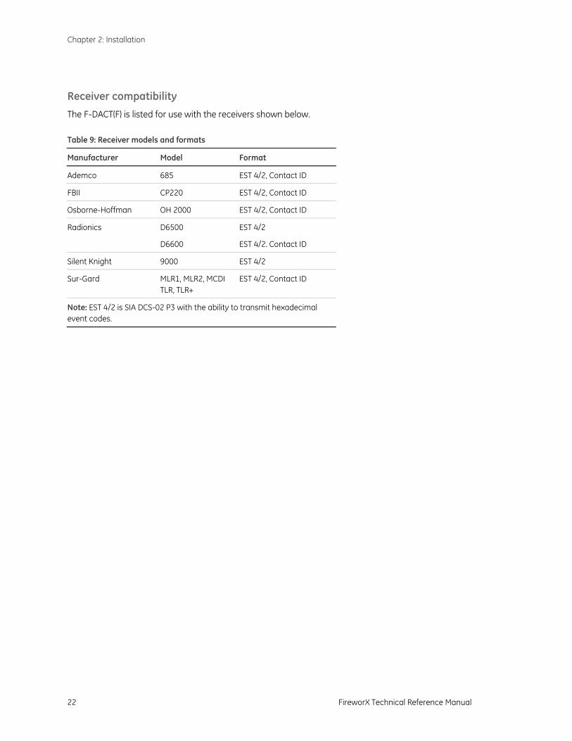
Receiver compatibility
The F-DACT(F) is listed for use with the receivers shown below. Table 9: Receiver models and formats
Manufacturer Model Format
Ademco 685 EST 4/2, Contact ID
FBII CP220 EST 4/2, Contact ID
Osborne-Hoffman OH 2000 EST 4/2, Contact ID
Radionics D6500 EST 4/2
D6600 EST 4/2. Contact ID
Silent Knight 9000 EST 4/2
Sur-Gard MLR1, MLR2, MCDI TLR, TLR+
EST 4/2, Contact ID
Note: EST 4/2 is SIA DCS-02 P3 with the ability to transmit hexadecimal event codes.
Chapter 2: Installation
FireworX Technical Reference Manual 23
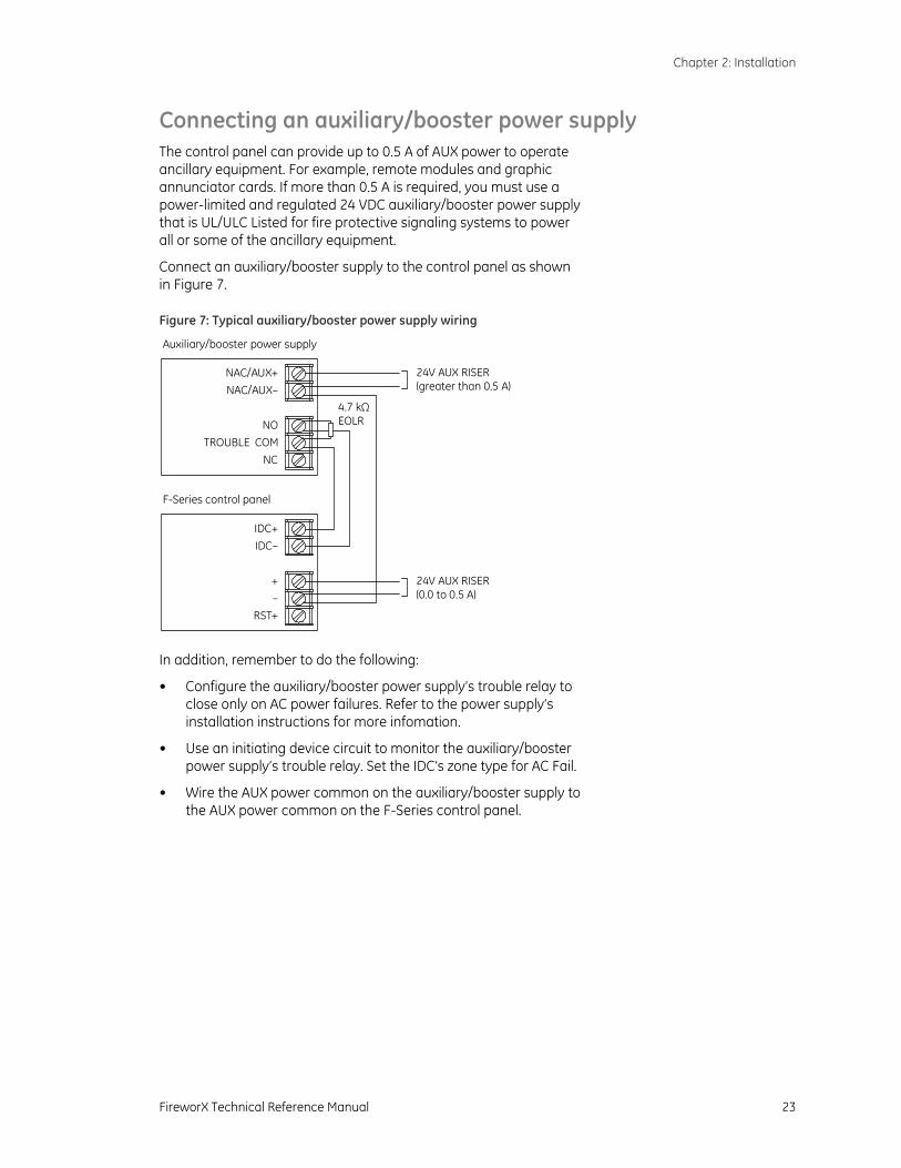
Connecting an auxiliary/booster power supply The control panel can provide up to 0.5 A of AUX power to operate ancillary equipment. For example, remote modules and graphic annunciator cards. If more than 0.5 A is required, you must use a power-limited and regulated 24 VDC auxiliary/booster power supply that is UL/ULC Listed for fire protective signaling systems to power all or some of the ancillary equipment.
Connect an auxiliary/booster supply to the control panel as shown in Figure 7.
Figure 7: Typical auxiliary/booster power supply wiring
–+
RST+
IDC+IDC–
NAC/AUX+NAC/AUX–
TROUBLE COMNO
NC
24V AUX RISER(greater than 0.5 A)
24V AUX RISER(0.0 to 0.5 A)
Auxiliary/booster power supply
F-Series control panel
4.7 kΩEOLR
In addition, remember to do the following:
• Configure the auxiliary/booster power supply’s trouble relay to close only on AC power failures. Refer to the power supply‘s installation instructions for more infomation.
• Use an initiating device circuit to monitor the auxiliary/booster power supply’s trouble relay. Set the IDC’s zone type for AC Fail.
• Wire the AUX power common on the auxiliary/booster supply to the AUX power common on the F-Series control panel.

Chapter 2: Installation
24 FireworX Technical Reference Manual

FireworX Technical Reference Manual 25
Chapter 3 Panel programming
Summary
This chapter provides instructions for programming the control panel using the panel’s keypad. It includes instructions for configuring the panel operation, initiating device circuits, and notification appliance circuits.
For dialer configuration instructions, see Chapter 4 “Dialer programming“ on page 43.
Instructions for programming the control panel using the Fire Systems Configuration Utility (FSCU) are provided in the FSCU’s online Help.
Content
UL 864 programming requirements • 26 Before you begin • 27
Programming methods • 27 Entering and exiting local program mode • 27 Selecting panel options • 27 Entering values for panel options • 28 When you finish • 28
Getting started • 29 Restoring panel default settings • 29 Enabling passcode protection • 29 Changing the passcode • 29 Detecting remote modules • 30
Configuring the panel • 31 Configuring initiating device circuits • 35 Configuring notification appliance circuits • 39 Programming coded alarm signals • 42
Chapter 3: Panel programming
26 FireworX Technical Reference Manual
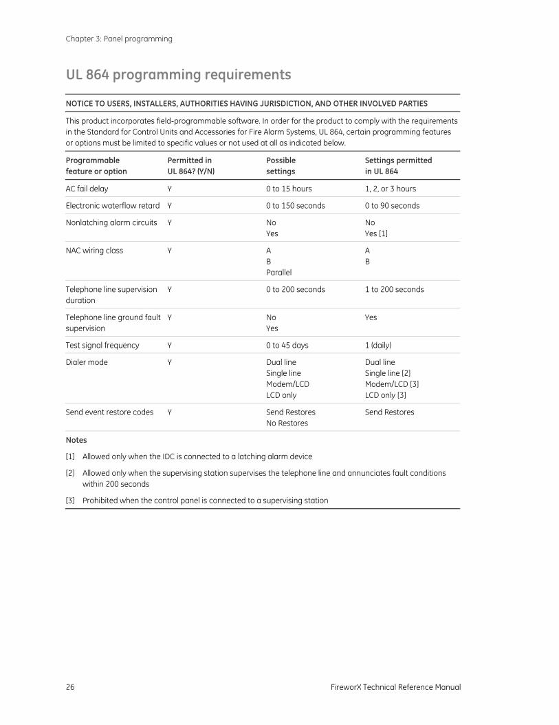
UL 864 programming requirements
NOTICE TO USERS, INSTALLERS, AUTHORITIES HAVING JURISDICTION, AND OTHER INVOLVED PARTIES
This product incorporates field-programmable software. In order for the product to comply with the requirements in the Standard for Control Units and Accessories for Fire Alarm Systems, UL 864, certain programming features or options must be limited to specific values or not used at all as indicated below.
Programmable feature or option
Permitted in UL 864? (Y/N)
Possible settings
Settings permitted in UL 864
AC fail delay Y 0 to 15 hours 1, 2, or 3 hours
Electronic waterflow retard Y 0 to 150 seconds 0 to 90 seconds
Nonlatching alarm circuits Y No Yes
No Yes [1]
NAC wiring class Y A B Parallel
A B
Telephone line supervision duration
Y 0 to 200 seconds 1 to 200 seconds
Telephone line ground fault supervision
Y No Yes
Yes
Test signal frequency Y 0 to 45 days 1 (daily)
Dialer mode Y Dual line Single line Modem/LCD LCD only
Dual line Single line [2] Modem/LCD [3] LCD only [3]
Send event restore codes Y Send Restores No Restores
Send Restores
Notes
[1] Allowed only when the IDC is connected to a latching alarm device
[2] Allowed only when the supervising station supervises the telephone line and annunciates fault conditions within 200 seconds
[3] Prohibited when the control panel is connected to a supervising station
Chapter 3: Panel programming
FireworX Technical Reference Manual 27
Before you begin
Programming methods
There are two ways you can program the control panel. You can use the control panel’s keypad (also called front panel programming). You can also use a computer and the Fire Systems Configuration Utility (FSCU).
To program the control panel using the FSCU, you must install an F-DACT(F) in the control panel. Configure the F-DACT(F) for dialer or modem operation.
Front panel programming does not require that you have an F-DACT(F) installed.
Entering and exiting local program mode The panel must be in local program mode before you can change any of the panel’s current settings.
To enter local program mode:
1. Install the jumper on J3 (PRG).
The panel status LEDs start flashing to indicate local program mode is activated.
2. If passcode protection is enabled, enter the passcode.
To exit local program mode:
1. Remove the jumper from J3 (PRG).
The panel automatically resets after the jumper on J3 is removed.
Programming mode times out about 90 seconds after the last programming button is pressed. The panel status LEDs start flashing to indicate that the panel has timed out.
Pressing the Signal Silence & Drill button returns you to local programming mode at the point you left. If passcode protection is enabled, you must enter the correct passcode to continue.
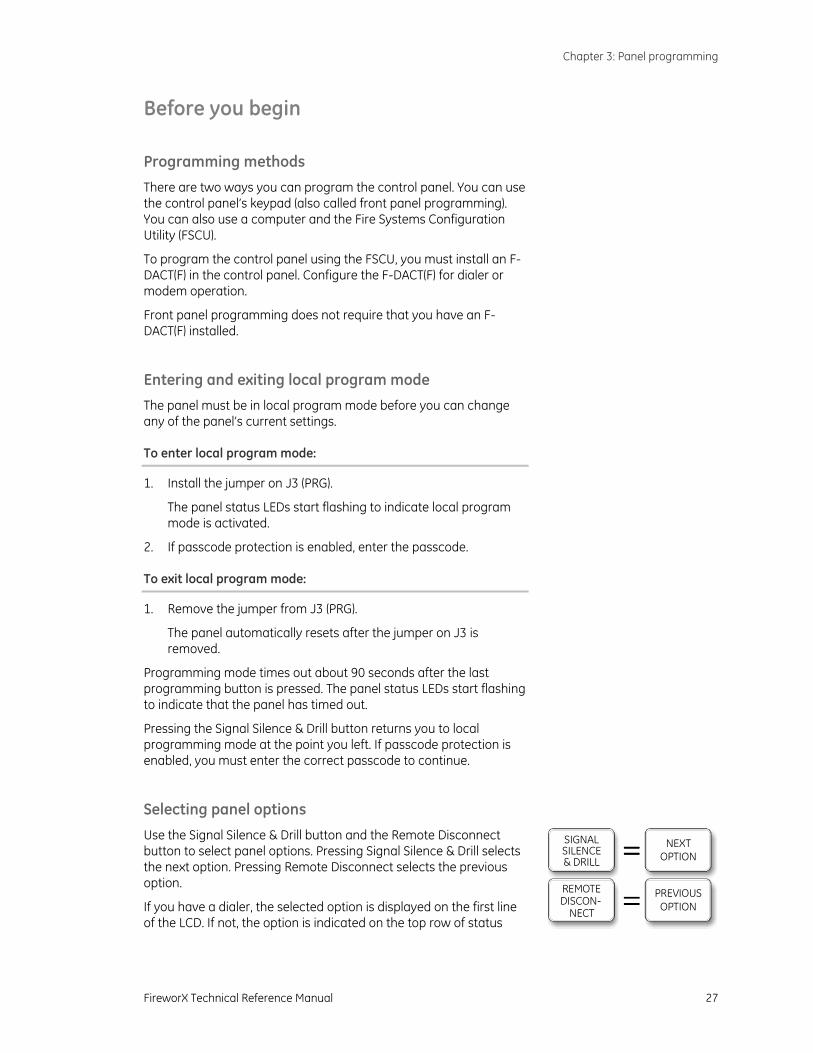
Selecting panel options
Use the Signal Silence & Drill button and the Remote Disconnect button to select panel options. Pressing Signal Silence & Drill selects the next option. Pressing Remote Disconnect selects the previous option.
If you have a dialer, the selected option is displayed on the first line of the LCD. If not, the option is indicated on the top row of status
SIGNALSILENCE& DRILL
NEXTOPTION
REMOTEDISCON-
NECT
PREVIOUSOPTION
Chapter 3: Panel programming
28 FireworX Technical Reference Manual
LEDs.
In the programming instructions that follow, when you see “select the <option_name> option,” press Signal Silence & Drill or Remote Disconnect until the option is displayed on the LCD or indicated on the status LEDs.
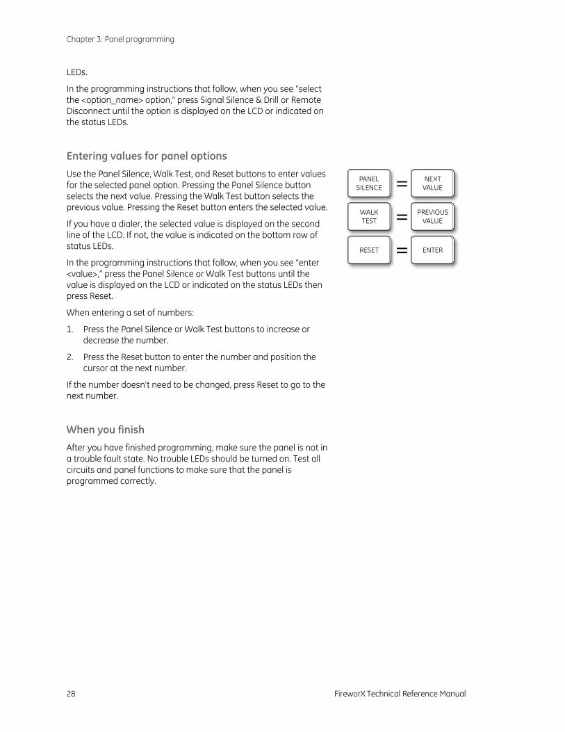
Entering values for panel options
Use the Panel Silence, Walk Test, and Reset buttons to enter values for the selected panel option. Pressing the Panel Silence button selects the next value. Pressing the Walk Test button selects the previous value. Pressing the Reset button enters the selected value.
If you have a dialer, the selected value is displayed on the second line of the LCD. If not, the value is indicated on the bottom row of status LEDs.
In the programming instructions that follow, when you see “enter <value>,” press the Panel Silence or Walk Test buttons until the value is displayed on the LCD or indicated on the status LEDs then press Reset.
When entering a set of numbers:
1. Press the Panel Silence or Walk Test buttons to increase or decrease the number.
2. Press the Reset button to enter the number and position the cursor at the next number.
If the number doesn’t need to be changed, press Reset to go to the next number.
When you finish
After you have finished programming, make sure the panel is not in a trouble fault state. No trouble LEDs should be turned on. Test all circuits and panel functions to make sure that the panel is programmed correctly.
NEXTVALUE
PREVIOUSVALUE
ENTER
PANELSILENCE
WALKTEST
RESET
Chapter 3: Panel programming
FireworX Technical Reference Manual 29
Getting started
Restoring panel default settings
Control panels are shipped from the factory with default settings for a typical system. Use the Load Defaults option to restore the panel default settings.
To restore panel default settings:
1. Select the Load Defaults option.
2. Enter Yes.
Enabling passcode protection Passcode protection prevents unauthorized access to the panel’s programming. The default passcode is 1111.
This option is only available when a dialer is installed.
To enable passcode protection:
1. Select the Enable Passcode option.
2. Enter Yes.
Changing the passcode
After enabling the passcode, you should change it at your earliest convenience. Write down the new passcode and store it in a safe place.
This option is only available when a dialer is installed and the passcode is enabled.
To change the passcode:
1. Select the Edit Passcode option.
2. Enter the new passcode.
A passcode consists of four characters. Valid characters are the numbers 0 to 9 and the letters A to F.
Caution: Restoring panel default settings disables passcode protection. If you want passcode protection you must enable it again.
Note: Restoring panel default settings doesn’t change the passcode and doesn’t restore dialer default settings.

Chapter 3: Panel programming
30 FireworX Technical Reference Manual
Detecting remote modules
Use the Find Peripherals option to detect which remote modules are connected to the control panel when you first configure the control panel and anytime you add or remove remote modules from the system.
To detect remote modules:
1. Select the Find Peripherals option.
2. Enter Yes.
The bottom status LEDs will flash until the control panel has completed the detection process. This may take up to 40 seconds. When finished, the control panel displays how many remote modules were detected, as shown in Table 10.
Table 10: Find Peripherals results
Step Option Values
LCD first line ALAR
M
TRO
UBL
E
SUP
POW
ER
DIS
ABLE
LCD second line WAT
ERFL
OW
ANN
TRO
UBL
E
BATT
TRO
UBL
E
GN
D F
AULT
SERV
ICE
DET
ECTO
R
9 Find Peripherals was XX now 00
was XX now 01
was XX now 02
was XX now 03
was XX now 04
was XX now 05
was XX now 06
was XX now 07
was XX now 08
was XX now 09
was XX now 10
was XX now 11
was XX now 12
was XX now 13
was XX now 14
Note: Do not remove the jumper on J3 (PRG) until the control panel has completed the detection process. If you do, you must remove all power from the panel before you can enter local programming mode again.

Chapter 3: Panel programming
FireworX Technical Reference Manual 31
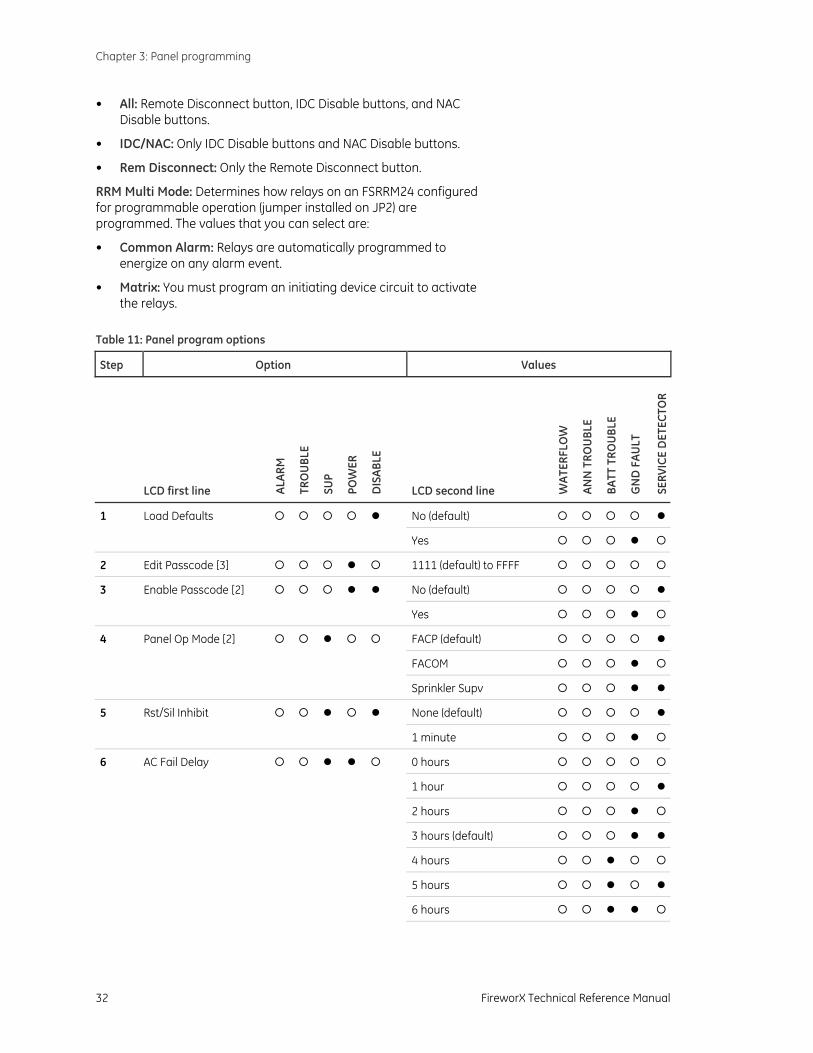
Configuring the panel To configure the panel, assign values to the panel program options as indicated in Table 11. Record your settings on the panel programming worksheet in Appendix B.
Follow this general sequence of steps:
1. Restore the panel default settings.
2. If passcode protection is required, enable the passcode. You should also change the passcode from its default value.
3. Starting with Panel Operating Mode, enter a value for each option. You can skip an option if its default value is acceptable.
4. Detect which remote modules are connected to the control panel.
The panel program options are described below.
Panel Op Mode: Determines the basic operation of the control panel. The values that you can select are:
• FACP: Panel operates as a fire alarm control panel. By default, all initiating device circuits are latching alarm circuits. A manual reset is required to return the panel to normal.
• FACOM: Panel operates as a dialer for fire alarm control panels that do not have a dialer. By default, all initiating device circuits are nonlatching alarm circuits. The control panel resets automatically after the central station receiver acknowledges that it received all events from the control panel.
• Sprinkler Supv: Panel operates as an unattended sprinkler supervisory panel. For alarm and waterflow events, the panel operates as a fire alarm control panel. For all other events, the control panel resets automatically after the central station receiver acknowledges that it has received all events from the control panel.
Rst/Sil Inhibit: Determines how long you must wait after an alarm event before you can silence notification appliances or reset the control panel. You can select None (to silence notification appliances or reset the control panel immediately) or 1 minute.
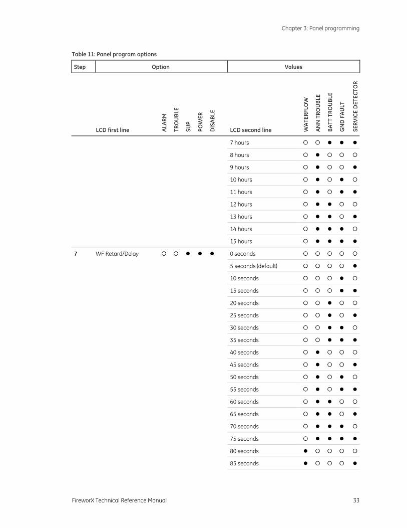
AC Fail Delay: Determines how long the panel must be without AC power or a remote AC fail zone type must be active before the dialer transmits an AC fail event. You can select between 0 and 15 hours.
WF Retard/Delay: Determines how long a waterflow switch must be closed before a waterflow-retard or a waterflow-retard/supervisory zone type is activated. You can select between 0 and 150 seconds.
Disable Lockout: Determines which control panel buttons are inoperable (locked out). The values that you can select are:
• None: No buttons are locked out.
Note: The panel operating mode option is only available when an F-DACT(F) is installed. By default, the panel operates as a fire alarm control panel.
Note: To meet UL 864 9th edition requirements, set AC Fail Delay for 1, 2, or 3 hours.
Note: To meet NFPA 72 2002 edition requirements, set WF Retard/Delay between 0 and 90 seconds.
Chapter 3: Panel programming
32 FireworX Technical Reference Manual
• All: Remote Disconnect button, IDC Disable buttons, and NAC Disable buttons.
• IDC/NAC: Only IDC Disable buttons and NAC Disable buttons.
• Rem Disconnect: Only the Remote Disconnect button.
RRM Multi Mode: Determines how relays on an FSRRM24 configured for programmable operation (jumper installed on JP2) are programmed. The values that you can select are:
• Common Alarm: Relays are automatically programmed to energize on any alarm event.
• Matrix: You must program an initiating device circuit to activate the relays.
Table 11: Panel program options
Step Option Values
LCD first line ALAR
M
TRO
UBL
E
SUP
POW
ER
DIS
ABLE
LCD second line WAT
ERFL
OW
ANN
TRO
UBL
E
BATT
TRO
UBL
E
GN
D F
AULT
SERV
ICE
DET
ECTO
R
1 Load Defaults No (default)
Yes
2 Edit Passcode [3] 1111 (default) to FFFF
3 Enable Passcode [2] No (default)
Yes
4 Panel Op Mode [2] FACP (default)
FACOM
Sprinkler Supv
5 Rst/Sil Inhibit None (default)
1 minute
6 AC Fail Delay 0 hours
1 hour
2 hours
3 hours (default)
4 hours
5 hours
6 hours
Chapter 3: Panel programming
FireworX Technical Reference Manual 33
Table 11: Panel program options
Step Option Values
LCD first line ALAR
M
TRO
UBL
E
SUP
POW
ER
DIS
ABLE
LCD second line WAT
ERFL
OW
ANN
TRO
UBL
E
BATT
TRO
UBL
E
GN
D F
AULT
SERV
ICE
DET
ECTO
R
7 hours
8 hours
9 hours
10 hours
11 hours
12 hours
13 hours
14 hours
15 hours
7 WF Retard/Delay 0 seconds
5 seconds (default)
10 seconds
15 seconds
20 seconds
25 seconds
30 seconds
35 seconds
40 seconds
45 seconds
50 seconds
55 seconds
60 seconds
65 seconds
70 seconds
75 seconds
80 seconds
85 seconds

Chapter 3: Panel programming
34 FireworX Technical Reference Manual
Table 11: Panel program options
Step Option Values
LCD first line ALAR
M
TRO
UBL
E
SUP
POW
ER
DIS
ABLE
LCD second line WAT
ERFL
OW
ANN
TRO
UBL
E
BATT
TRO
UBL
E
GN
D F
AULT
SERV
ICE
DET
ECTO
R
90 seconds
95 seconds
100 seconds
105 seconds
110 seconds
115 seconds
120 seconds
125 seconds
130 seconds
135 seconds
140 seconds
145 seconds
150 seconds
8 Disable Lockout None (default)
All
IDC/NAC
Remote Disconnect
9 Find Peripherals [4] XX now on buss
Find devices
10 RRM Multi Mode [5] Common Alarm (default)
Matrix
Notes
1. = OFF, = ON
[2] Available only when an F-DACT(F) is installed
[3] Available only when an F-DACT(F) is installed and the panel’s Enable Passcode option is set for Yes
[4] For result display options, see Table 10 on page 30
[5] Available only when an FSRRM24 configured for programmable operation (jumper installed on JP2) is detected on the peripheral bus
Chapter 3: Panel programming
FireworX Technical Reference Manual 35
Configuring initiating device circuits To configure the initiating device circuits (IDCs), assign values to the IDC program options as indicated in Table 12. Record your settings on the IDC programming worksheet in Appendix B.
Follow this general sequence of steps:
1. Select the IDC zone type option. IDC 1 is automatically selected for you.
2. Enter the IDC zone type value for each IDC. To select a different IDC, press the IDC’s disable button. The panel indicates which IDC you are programming by turning on the IDC’s trouble LED.
If the IDC is an alarm zone type or a waterflow zone type, press the Disable button for each NAC that you want the IDC to turn on. The panel indicates which NAC you selected by turning on the NAC’s trouble LED.
3. Select the next option and enter a value for each IDC before proceeding to the next option.
The IDC programming options are described below.
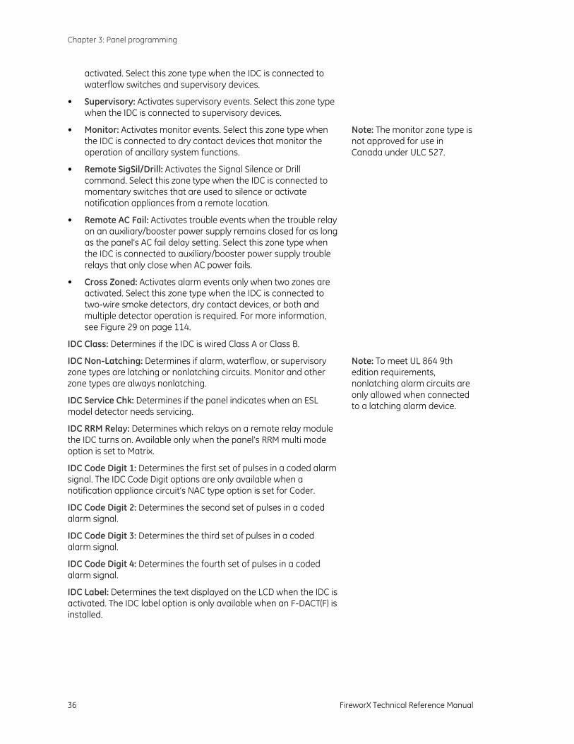
IDC Zone Type: Determines the type of event that the IDC activates and other operating characteristics. The values that you can select are:
• Alarm-unverified: Activates alarm events. Select this zone type when the IDC is connected to two-wire smoke detectors, dry contact devices, or both.
• Alarm-verified: Activates alarm events immediately for dry contact devices and at the end of the alarm verification cycle for two-wire smoke detectors. Select this zone type when the IDC is connected to two-wire smoke detectors, dry contact devices, or both.
• WaterFlow-retard: Activates alarm events when a waterflow switch remains closed for as long as the panel’s waterflow retard/delay setting. Select this zone type when the IDC is only connected to waterflow switches.
• WaterFlow: Activates alarm events when a waterflow switch closes, regardless of the panel’s waterflow retard/delay setting. Select this zone type when the IDC is only connected to waterflow switches.
• WF-retard/Supv: Activates alarm events when a waterflow switch remains closed for as long as the panel’s waterflow retard/delay setting and supervisory events when a supervisory device is activated. Select this zone type when the IDC is connected to waterflow switches and supervisory devices.
• WF/Supervisory: Activates alarm events when a waterflow switch closes, regardless of the panel’s waterflow retard/delay setting, and supervisory events when a supervisory device is
Chapter 3: Panel programming
36 FireworX Technical Reference Manual
activated. Select this zone type when the IDC is connected to waterflow switches and supervisory devices.
• Supervisory: Activates supervisory events. Select this zone type when the IDC is connected to supervisory devices.
• Monitor: Activates monitor events. Select this zone type when the IDC is connected to dry contact devices that monitor the operation of ancillary system functions.
• Remote SigSil/Drill: Activates the Signal Silence or Drill command. Select this zone type when the IDC is connected to momentary switches that are used to silence or activate notification appliances from a remote location.
• Remote AC Fail: Activates trouble events when the trouble relay on an auxiliary/booster power supply remains closed for as long as the panel’s AC fail delay setting. Select this zone type when the IDC is connected to auxiliary/booster power supply trouble relays that only close when AC power fails.
• Cross Zoned: Activates alarm events only when two zones are activated. Select this zone type when the IDC is connected to two-wire smoke detectors, dry contact devices, or both and multiple detector operation is required. For more information, see Figure 29 on page 114.
IDC Class: Determines if the IDC is wired Class A or Class B.
IDC Non-Latching: Determines if alarm, waterflow, or supervisory zone types are latching or nonlatching circuits. Monitor and other zone types are always nonlatching.
IDC Service Chk: Determines if the panel indicates when an ESL model detector needs servicing.
IDC RRM Relay: Determines which relays on a remote relay module the IDC turns on. Available only when the panel’s RRM multi mode option is set to Matrix.
IDC Code Digit 1: Determines the first set of pulses in a coded alarm signal. The IDC Code Digit options are only available when a notification appliance circuit’s NAC type option is set for Coder.
IDC Code Digit 2: Determines the second set of pulses in a coded alarm signal.
IDC Code Digit 3: Determines the third set of pulses in a coded alarm signal.
IDC Code Digit 4: Determines the fourth set of pulses in a coded alarm signal.
IDC Label: Determines the text displayed on the LCD when the IDC is activated. The IDC label option is only available when an F-DACT(F) is installed.
Note: The monitor zone type is not approved for use in Canada under ULC 527.
Note: To meet UL 864 9th edition requirements, nonlatching alarm circuits are only allowed when connected to a latching alarm device.
Chapter 3: Panel programming
FireworX Technical Reference Manual 37
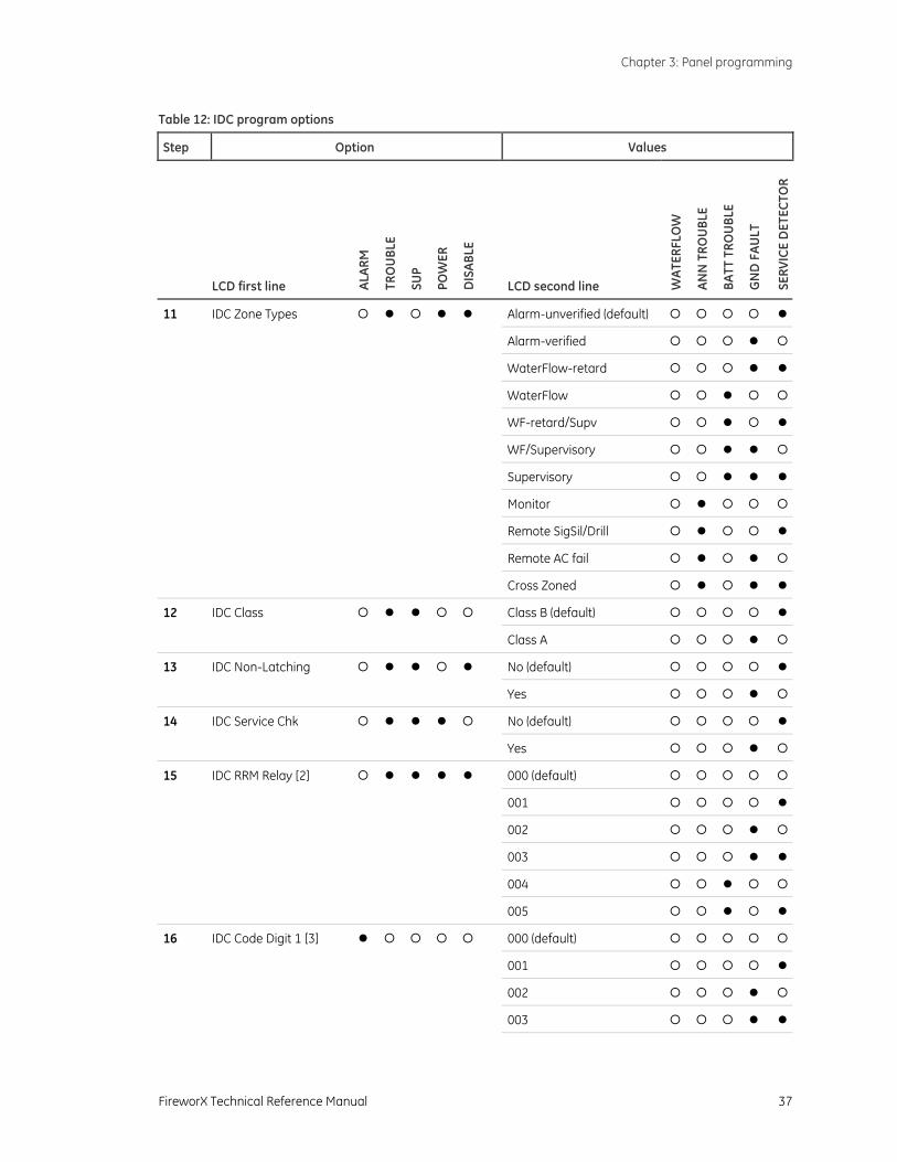
Table 12: IDC program options
Step Option Values
LCD first line ALAR
M
TRO
UBL
E
SUP
POW
ER
DIS
ABLE
LCD second line WAT
ERFL
OW
ANN
TRO
UBL
E
BATT
TRO
UBL
E
GN
D F
AULT
SERV
ICE
DET
ECTO
R
11 IDC Zone Types Alarm-unverified (default)
Alarm-verified
WaterFlow-retard
WaterFlow
WF-retard/Supv
WF/Supervisory
Supervisory
Monitor
Remote SigSil/Drill
Remote AC fail
Cross Zoned
12 IDC Class Class B (default)
Class A
13 IDC Non-Latching No (default)
Yes
14 IDC Service Chk No (default)
Yes
15 IDC RRM Relay [2] 000 (default)
001
002
003
004
005
16 IDC Code Digit 1 [3] 000 (default)
001
002
003
Chapter 3: Panel programming
38 FireworX Technical Reference Manual
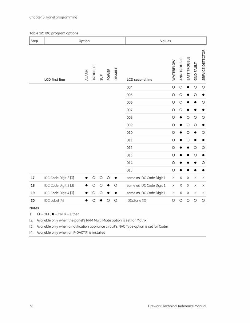
Table 12: IDC program options
Step Option Values
LCD first line ALAR
M
TRO
UBL
E
SUP
POW
ER
DIS
ABLE
LCD second line WAT
ERFL
OW
ANN
TRO
UBL
E
BATT
TRO
UBL
E
GN
D F
AULT
SERV
ICE
DET
ECTO
R
004
005
006
007
008
009
010
011
012
013
014
015
17 IDC Code Digit 2 [3] same as IDC Code Digit 1 X X X X X
18 IDC Code Digit 3 [3] same as IDC Code Digit 1 X X X X X
19 IDC Code Digit 4 [3] same as IDC Code Digit 1 X X X X X
20 IDC Label [4] IDC/Zone XX
Notes
1. = OFF, = ON, X = Either
[2] Available only when the panel’s RRM Multi Mode option is set for Matrix
[3] Available only when a notification appliance circuit’s NAC Type option is set for Coder
[4] Available only when an F-DACT(F) is installed
Chapter 3: Panel programming
FireworX Technical Reference Manual 39
Configuring notification appliance circuits To configure the notification appliance circuits (NACs), assign values to the NAC program options as indicated in Table 13. Record your settings on the initiating device circuit programming worksheet in Appendix B.
Follow this general sequence of steps:
1. Select the NAC type option. NAC 1 is automatically selected.
2. Enter the NAC type value for each NAC. To select a different NAC, press the NAC’s disable button. The panel indicates which NAC you are programming by turning on the NAC’s trouble LED.
3. Select the next option and enter a value for each NAC before proceeding to the next option.
NAC program options are described below.
NAC type: Determines the type of signal that the NAC outputs and other operating characteristics. The values that you can select are:
• Continuous: Outputs an unsynchronized 24-volt continuous (steady) signal. Select this NAC type when the NAC is connected to compatible audible and visible notification appliances, other than Genesis.
• Temporal (3-3-3): Outputs an unsynchronized 24-volt temporal signal. Select this NAC type when the NAC is connected to compatible audible notification appliances, other than Genesis, that are designed or configured to output a steady tone.
• GENESIS: Outputs a synchronized 24-volt continuous (steady) signal, and a horn-only signal silence command. Select this NAC type when the NAC is connected to Genesis audible and visible notification appliances and Signal Silence is for horns only.
• GENESIS (AV Sil): Outputs a synchronized 24-volt continuous (steady) signal. Select this NAC type when the NAC is connected to Genesis audible and visible notification appliances and Signal Silence is for both horns and strobes.
• Coder: Outputs an unsynchronized 24-volt coded signal that is four rounds of an IDC’s zone code. Select this NAC type when the NAC is connected to compatible audible notification appliances designed or configured to output a steady tone.
• City Tie: Outputs an unsynchronized 24-volt continuous (steady) signal that can’t be silenced or disabled. Select this NAC type when the NAC is connected to a city tie module.
NAC Class: Determines if the NAC is wired Class A, Class B.
Automatic Sig Silence: Determines how long NACs stay on after an alarm event before they are automatically silenced. Select between 0 minutes (NACs stay on indefinitely) and 30 minutes.
NAC Silenceable: Determines if the NAC can be silenced.
Chapter 3: Panel programming
40 FireworX Technical Reference Manual
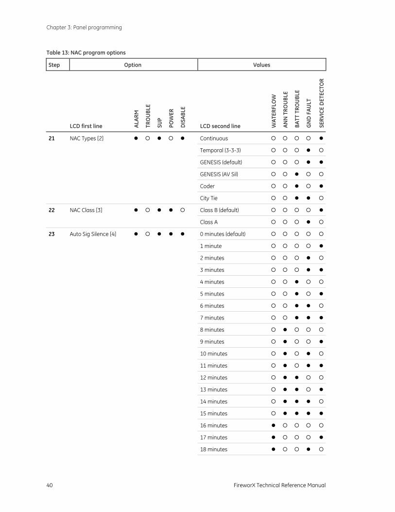
Table 13: NAC program options
Step Option Values
LCD first line ALAR
M
TRO
UBL
E
SUP
POW
ER
DIS
ABLE
LCD second line WAT
ERFL
OW
ANN
TRO
UBL
E
BATT
TRO
UBL
E
GN
D F
AULT
SERV
ICE
DET
ECTO
R
21 NAC Types [2] Continuous
Temporal (3-3-3)
GENESIS (default)
GENESIS (AV Sil)
Coder
City Tie
22 NAC Class [3] Class B (default)
Class A
23 Auto Sig Silence [4] 0 minutes (default)
1 minute
2 minutes
3 minutes
4 minutes
5 minutes
6 minutes
7 minutes
8 minutes
9 minutes
10 minutes
11 minutes
12 minutes
13 minutes
14 minutes
15 minutes
16 minutes
17 minutes
18 minutes
Chapter 3: Panel programming
FireworX Technical Reference Manual 41
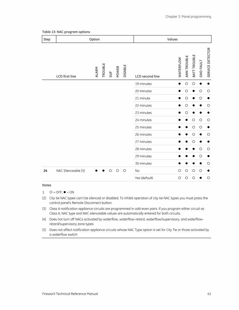
Table 13: NAC program options
Step Option Values
LCD first line ALAR
M
TRO
UBL
E
SUP
POW
ER
DIS
ABLE
LCD second line WAT
ERFL
OW
ANN
TRO
UBL
E
BATT
TRO
UBL
E
GN
D F
AULT
SERV
ICE
DET
ECTO
R
19 minutes
20 minutes
21 minute
22 minutes
23 minutes
24 minutes
25 minutes
26 minutes
27 minutes
28 minutes
29 minutes
30 minutes
24 NAC Silenceable [5] No
Yes (default)
Notes
1. = OFF, = ON
[2] City tie NAC types can’t be silenced or disabled. To inhibit operation of city tie NAC types you must press the control panel’s Remote Disconnect button.
[3] Class A notification appliance circuits are programmed in odd-even pairs. If you program either circuit as Class A, NAC type and NAC silenceable values are automatically entered for both circuits.
[4] Does not turn off NACs activated by waterflow, waterflow-retard, waterflow/supervisory, and waterflow-retard/supervisory zone types
[5] Does not affect notification appliance circuits whose NAC Type option is set for City Tie or those activated by a waterflow switch
Chapter 3: Panel programming
42 FireworX Technical Reference Manual
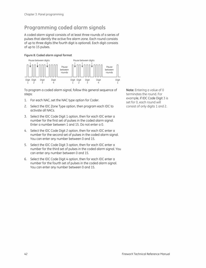
Programming coded alarm signals A coded alarm signal consists of at least three rounds of a series of pulses that identify the active fire alarm zone. Each round consists of up to three digits (the fourth digit is optional). Each digit consists of up to 15 pulses.
Figure 8: Coded alarm signal format
Digit1
Pause between digits
Digit2
Digit3
Digit4
Pausebetweenrounds
Pausebetweenrounds
Pause between digits
Digit1
Digit2
Digit3
Digit4
Digit1
To program a coded alarm signal, follow this general sequence of steps:
1. For each NAC, set the NAC type option for Coder.
2. Select the IDC Zone Type option, then program each IDC to activate all NACs.
3. Select the IDC Code Digit 1 option, then for each IDC enter a number for the first set of pulses in the coded alarm signal. Enter a number between 1 and 15. Do not enter a 0.
4. Select the IDC Code Digit 2 option, then for each IDC enter a number for the second set of pulses in the coded alarm signal. You can enter any number between 0 and 15.
5. Select the IDC Code Digit 3 option, then for each IDC enter a number for the third set of pulses in the coded alarm signal. You can enter any number between 0 and 15.
6. Select the IDC Code Digit 4 option, then for each IDC enter a number for the fourth set of pulses in the coded alarm signal. You can enter any number between 0 and 15.
Note: Entering a value of 0 terminates the round. For example, if IDC Code Digit 3 is set for 0, each round will consist of only digits 1 and 2.
FireworX Technical Reference Manual 43
Chapter 4 Dialer programming
Summary
This chapter provides instructions for programming the dialer using the panel’s keypad. It includes instructions for setting the system clock, setting daylight saving time, and configuring the dialer.
Instructions for programming the dialer using the Fire Systems Configuration Utility (FSCU) are provided in the FSCU’s online Help.
Content Before you begin • 44
Programmable features • 44 Entering and exiting dialer program mode • 44 Selecting dialer options • 45 Entering values for dialer options • 45 Entering telephone numbers for dialer accounts • 45
Getting started • 47 Setting the system clock • 47 Setting daylight saving time options • 47 Selecting a dialer mode • 48
Setting account options • 49 Setting dialer options • 51 Setting system event transmit options • 53 Setting IDC event transmit options • 55 Setting NAC event transmit options • 56 Setting system 4/2 event activation code options • 57 Setting IDC 4/2 event activation code options • 59 Setting NAC 4/2 event activation code options • 60 Restoring dialer default settings • 61
Chapter 4: Dialer programming
44 FireworX Technical Reference Manual
Before you begin Programming the F-DACT(F) sets up the dialer for communication with the central monitoring station. It also sets a number of other options such as date, time, phone numbers, etc. Many of the options have default settings, which are detailed below.
Programmable features
Here are some of the dialer’s programmable features:
• Passcode protection: Prevents unauthorized access to the panel’s programming.
• Daylight saving time: Determines how much the system clock is adjusted for daylight saving time and when it is adjusted.
• Dialer operating mode: Determines if the F-DACT(F) operates as a dual- or single-line dialer, a modem, or only an LCD text display.
• Blind call dialing: Determines if the F-DACT(F) can dial out without waiting for a dial tone.
• Callback security: Prevents someone at another location from dialing into your control panel to access information.
You can only program this feature using the Fire Systems Configuration Utility:
• Swinger shutdown: Limits the number of consecutive identical events transmitted for the same point.
Entering and exiting dialer program mode Dialer program mode provides a separate set of options just for the dialer. It is only available when a dialer is installed.
To enter dialer program mode:
1. Install the jumper on J3 (PRG).
The panel status LEDs start flashing to indicate local program mode is activated.
2. If passcode protection is enabled, enter the passcode.
3. Select the Program DACT option. The quickest way is to press Signal Silence & Drill then Remote Disconnect.
4. Enter Yes.
To exit dialer program mode:
1. Remove the jumper from J3 (PRG).
Chapter 4: Dialer programming
FireworX Technical Reference Manual 45
The panel automatically resets after the jumper on J3 is removed.
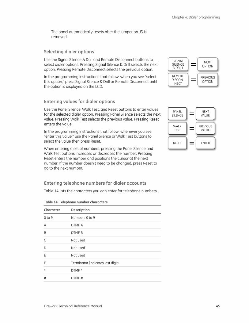
Selecting dialer options
Use the Signal Silence & Drill and Remote Disconnect buttons to select dialer options. Pressing Signal Silence & Drill selects the next option. Pressing Remote Disconnect selects the previous option.
In the programming instructions that follow, when you see “select this option,” press Signal Silence & Drill or Remote Disconnect until the option is displayed on the LCD.
Entering values for dialer options
Use the Panel Silence, Walk Test, and Reset buttons to enter values for the selected dialer option. Pressing Panel Silence selects the next value. Pressing Walk Test selects the previous value. Pressing Reset enters the value.
In the programming instructions that follow, whenever you see “enter this value,” use the Panel Silence or Walk Test buttons to select the value then press Reset.
When entering a set of numbers, pressing the Panel Silence and Walk Test buttons increases or decreases the number. Pressing Reset enters the number and positions the cursor at the next number. If the number doesn’t need to be changed, press Reset to go to the next number.
Entering telephone numbers for dialer accounts Table 14 lists the characters you can enter for telephone numbers. Table 14: Telephone number characters
Character Description
0 to 9 Numbers 0 to 9
A DTMF A
B DTMF B
C Not used
D Not used
E Not used
F Terminator (indicates last digit)
* DTMF *
# DTMF #
SIGNALSILENCE& DRILL
NEXTOPTION
REMOTEDISCON-
NECT
PREVIOUSOPTION
NEXTVALUE
PREVIOUSVALUE
ENTER
PANELSILENCE
WALKTEST
RESET

Chapter 4: Dialer programming
46 FireworX Technical Reference Manual
Table 14: Telephone number characters
Character Description
, DTMF , (inserts a pause between digits)
Chapter 4: Dialer programming
FireworX Technical Reference Manual 47
Getting started
Setting the system clock
The control panel uses a system clock to time-stamp events. Time is presented in 24-hour format. Dates are presented in month-day-year format.
To set the system clock:
1. Select the Date option.
2. Enter the month, day, and year.
3. Under Time, enter the time in hours and minutes
4. Under Current Day, enter the day of the week.
Setting daylight saving time options The daylight saving time options determine how much the system clock is adjusted for daylight saving time and when it is adjusted.
The default DST settings adjust the system clock forward one hour on the second Sunday in March at 2:00 a.m. and back one hour on the first Sunday in November at 2:00 a.m.
To change daylight saving time settings:
1. Select the Daylight Saving option.
2. Enter Set.
3. For DST Adjustment, enter how many minutes you want the system clock adjusted when DST begins and ends. The default value is 60 minutes.
Enter 00 minutes to prevent daylight saving time from automatically adjusting the system clock.
4. For DST Start Month, enter the month that DST begins. The default value is 03 (March).
5. For DST Start Week, enter the week that DST begins. The default value is 2nd.
6. For DST Start Day, enter the day that DST begins. The default value is Sunday.
7. For DST Start Hour, enter the hour that DST begins. The default value is 02 (2:00 a.m.).
The start hour is in 24-hour format. 00 = 12:00 a.m. (midnight), 01 = 1:00 a.m., 12 = 12:00 p.m. (noon), 23 = 11:00 p.m.
8. For DST End Month, enter the month that DST ends. The default value is 11 (November).
Chapter 4: Dialer programming
48 FireworX Technical Reference Manual
9. For DST End Week, enter the week that DST ends. The default value is First.
10. For DST End Day, enter the day that DST ends. The default value is Sunday.
11. For DST End Hour, enter the hour that DST ends. The default value is 02 (2:00 a.m.).
Selecting a dialer mode
The dialer mode option determines how the F-DACT(F) operates. The values that you can select are:
• Dual-Line DACT: Dialer is used to transmit event codes to a central station on LINE 1 and LINE 2, and to perform modem functions/LCD functions.
• Single-Line DACT: Dialer is used to transmit event codes to a central station on LINE 1 only, and to perform modem functions/LCD functions.
• Modem/LCD only: Dialer is used to communicate with a computer running the FSCU, and to display text. Dialer functions are disabled.
• LCD only: Dialer is only used to display text. Dialer and modem functions are disabled.
If Single-Line DACT is selected, dual-line programming is skipped. If Modem/LCD only is selected, all account and receiver related programming is skipped. If LCD only is selected, all account, receiver, and telephone related programming is skipped.
To select a dialer mode:
1. Select the Dialer Mode option.
2. Enter a mode.
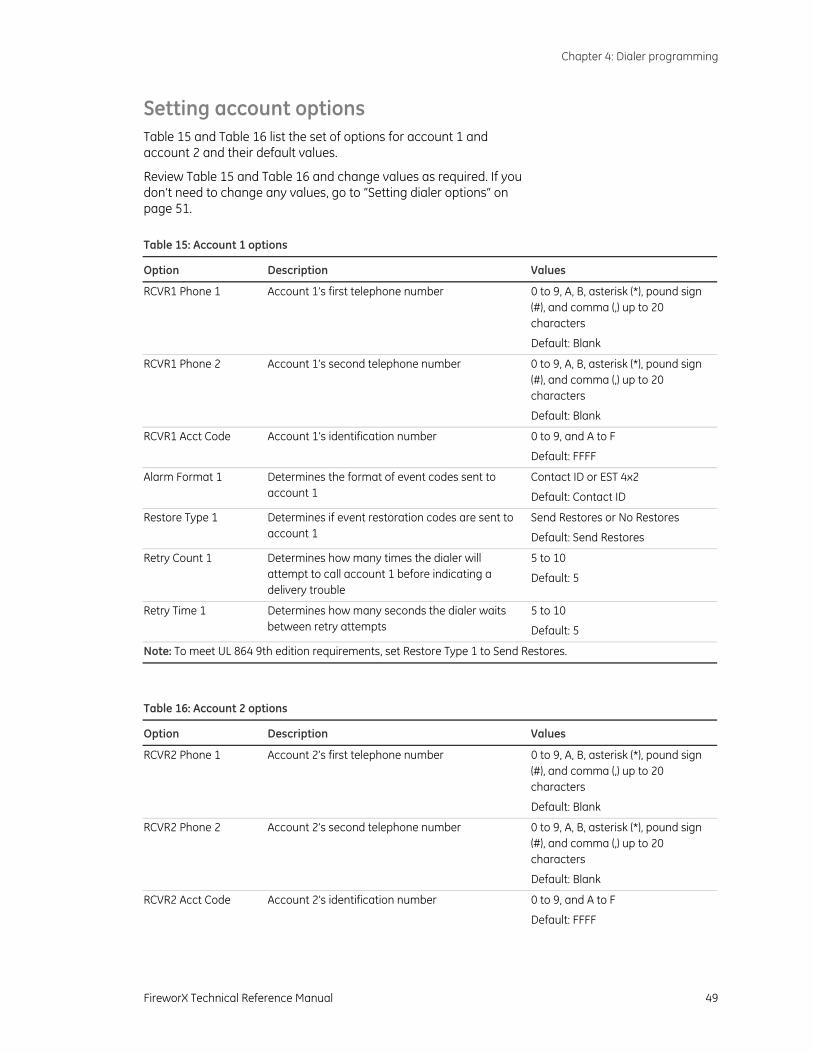
Chapter 4: Dialer programming
FireworX Technical Reference Manual 49
Setting account options Table 15 and Table 16 list the set of options for account 1 and account 2 and their default values.
Review Table 15 and Table 16 and change values as required. If you don’t need to change any values, go to “Setting dialer options“ on page 51. Table 15: Account 1 options
Option Description Values
RCVR1 Phone 1 Account 1’s first telephone number 0 to 9, A, B, asterisk (*), pound sign (#), and comma (,) up to 20 characters
Default: Blank
RCVR1 Phone 2 Account 1’s second telephone number 0 to 9, A, B, asterisk (*), pound sign (#), and comma (,) up to 20 characters
Default: Blank
RCVR1 Acct Code Account 1’s identification number 0 to 9, and A to F
Default: FFFF
Alarm Format 1 Determines the format of event codes sent to account 1
Contact ID or EST 4x2
Default: Contact ID
Restore Type 1 Determines if event restoration codes are sent to account 1
Send Restores or No Restores
Default: Send Restores
Retry Count 1 Determines how many times the dialer will attempt to call account 1 before indicating a delivery trouble
5 to 10
Default: 5
Retry Time 1 Determines how many seconds the dialer waits between retry attempts
5 to 10
Default: 5
Note: To meet UL 864 9th edition requirements, set Restore Type 1 to Send Restores.
Table 16: Account 2 options
Option Description Values
RCVR2 Phone 1 Account 2’s first telephone number 0 to 9, A, B, asterisk (*), pound sign (#), and comma (,) up to 20 characters
Default: Blank
RCVR2 Phone 2 Account 2’s second telephone number 0 to 9, A, B, asterisk (*), pound sign (#), and comma (,) up to 20 characters
Default: Blank
RCVR2 Acct Code Account 2’s identification number 0 to 9, and A to F
Default: FFFF
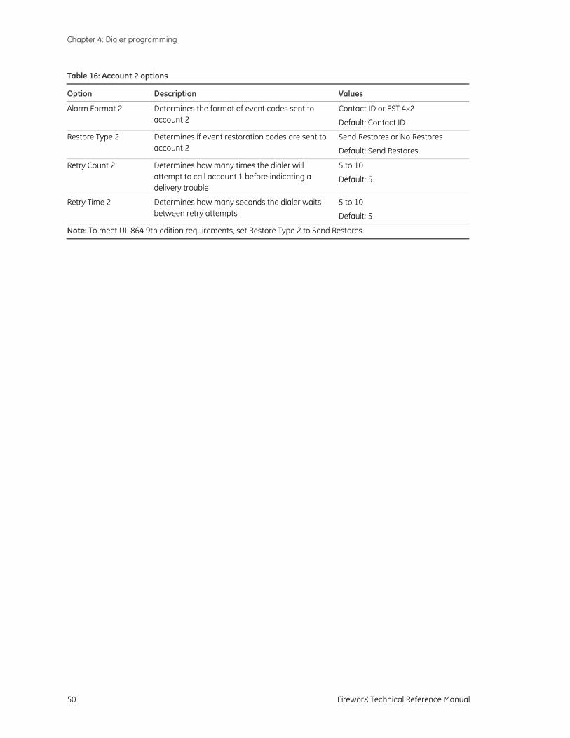
Chapter 4: Dialer programming
50 FireworX Technical Reference Manual
Table 16: Account 2 options
Option Description Values
Alarm Format 2 Determines the format of event codes sent to account 2
Contact ID or EST 4x2
Default: Contact ID
Restore Type 2 Determines if event restoration codes are sent to account 2
Send Restores or No Restores
Default: Send Restores
Retry Count 2 Determines how many times the dialer will attempt to call account 1 before indicating a delivery trouble
5 to 10
Default: 5
Retry Time 2 Determines how many seconds the dialer waits between retry attempts
5 to 10
Default: 5
Note: To meet UL 864 9th edition requirements, set Restore Type 2 to Send Restores.
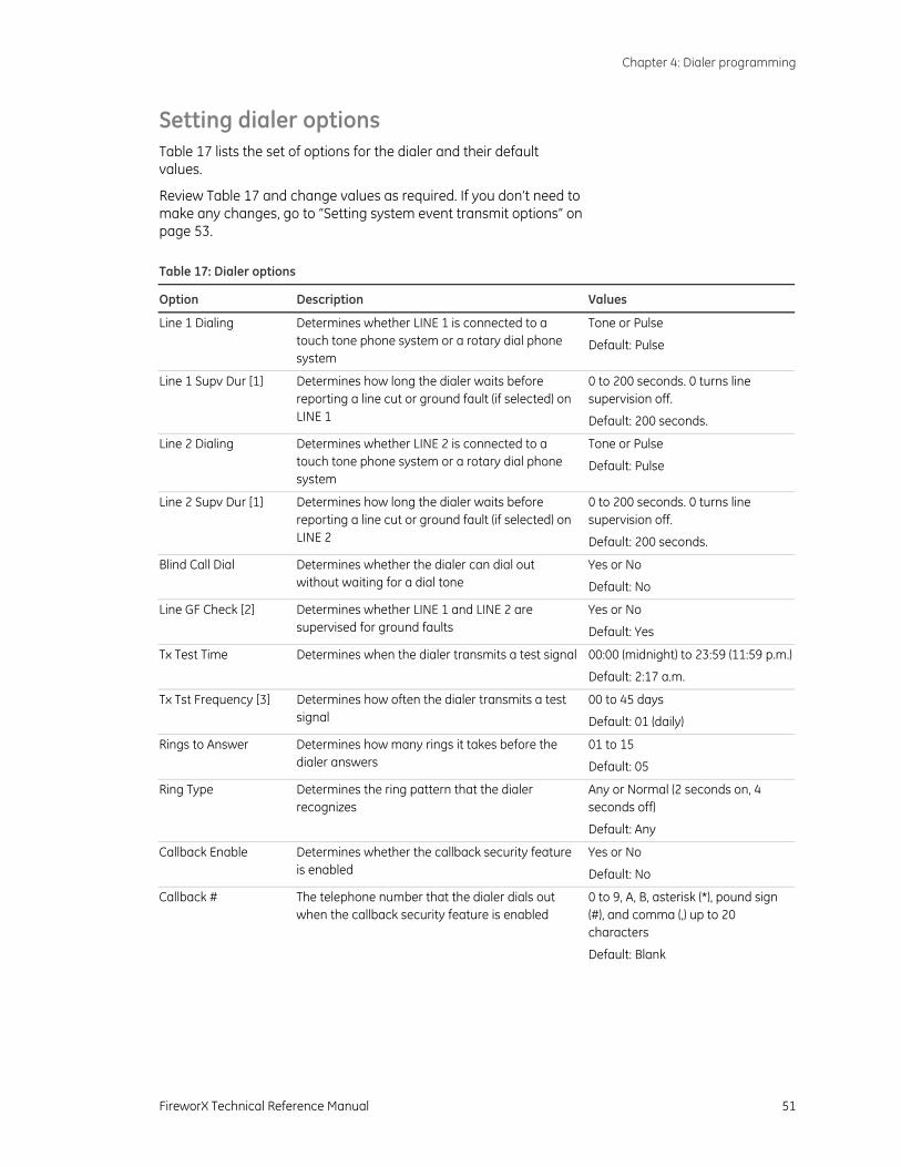
Chapter 4: Dialer programming
FireworX Technical Reference Manual 51
Setting dialer options Table 17 lists the set of options for the dialer and their default values.
Review Table 17 and change values as required. If you don’t need to make any changes, go to “Setting system event transmit options“ on page 53. Table 17: Dialer options
Option Description Values
Line 1 Dialing Determines whether LINE 1 is connected to a touch tone phone system or a rotary dial phone system
Tone or Pulse
Default: Pulse
Line 1 Supv Dur [1] Determines how long the dialer waits before reporting a line cut or ground fault (if selected) on LINE 1
0 to 200 seconds. 0 turns line supervision off.
Default: 200 seconds.
Line 2 Dialing Determines whether LINE 2 is connected to a touch tone phone system or a rotary dial phone system
Tone or Pulse
Default: Pulse
Line 2 Supv Dur [1] Determines how long the dialer waits before reporting a line cut or ground fault (if selected) on LINE 2
0 to 200 seconds. 0 turns line supervision off.
Default: 200 seconds.
Blind Call Dial Determines whether the dialer can dial out without waiting for a dial tone
Yes or No
Default: No
Line GF Check [2] Determines whether LINE 1 and LINE 2 are supervised for ground faults
Yes or No
Default: Yes
Tx Test Time Determines when the dialer transmits a test signal 00:00 (midnight) to 23:59 (11:59 p.m.)
Default: 2:17 a.m.
Tx Tst Frequency [3] Determines how often the dialer transmits a test signal
00 to 45 days
Default: 01 (daily)
Rings to Answer Determines how many rings it takes before the dialer answers
01 to 15
Default: 05
Ring Type Determines the ring pattern that the dialer recognizes
Any or Normal (2 seconds on, 4 seconds off)
Default: Any
Callback Enable Determines whether the callback security feature is enabled
Yes or No
Default: No
Callback # The telephone number that the dialer dials out when the callback security feature is enabled
0 to 9, A, B, asterisk (*), pound sign (#), and comma (,) up to 20 characters
Default: Blank
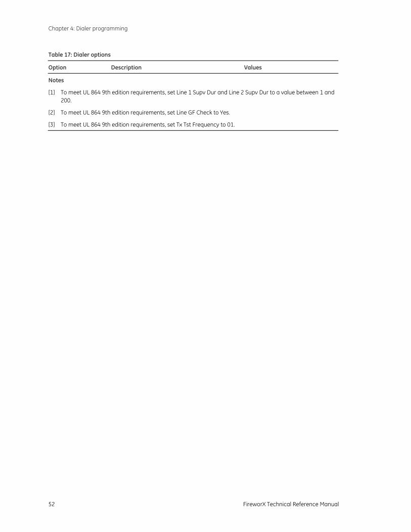
Chapter 4: Dialer programming
52 FireworX Technical Reference Manual
Table 17: Dialer options
Option Description Values
Notes
[1] To meet UL 864 9th edition requirements, set Line 1 Supv Dur and Line 2 Supv Dur to a value between 1 and 200.
[2] To meet UL 864 9th edition requirements, set Line GF Check to Yes.
[3] To meet UL 864 9th edition requirements, set Tx Tst Frequency to 01.
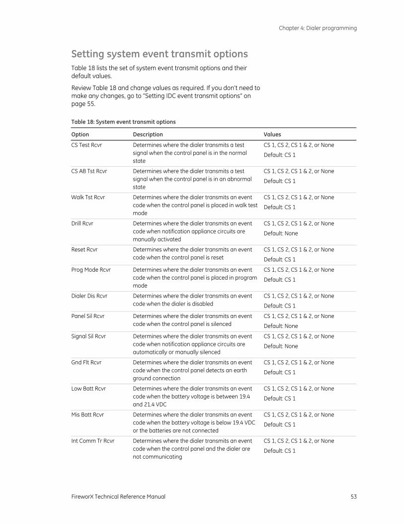
Chapter 4: Dialer programming
FireworX Technical Reference Manual 53
Setting system event transmit options Table 18 lists the set of system event transmit options and their default values.
Review Table 18 and change values as required. If you don’t need to make any changes, go to “Setting IDC event transmit options“ on page 55. Table 18: System event transmit options
Option Description Values
CS Test Rcvr Determines where the dialer transmits a test signal when the control panel is in the normal state
CS 1, CS 2, CS 1 & 2, or None
Default: CS 1
CS AB Tst Rcvr Determines where the dialer transmits a test signal when the control panel is in an abnormal state
CS 1, CS 2, CS 1 & 2, or None
Default: CS 1
Walk Tst Rcvr Determines where the dialer transmits an event code when the control panel is placed in walk test mode
CS 1, CS 2, CS 1 & 2, or None
Default: CS 1
Drill Rcvr Determines where the dialer transmits an event code when notification appliance circuits are manually activated
CS 1, CS 2, CS 1 & 2, or None
Default: None
Reset Rcvr Determines where the dialer transmits an event code when the control panel is reset
CS 1, CS 2, CS 1 & 2, or None
Default: CS 1
Prog Mode Rcvr Determines where the dialer transmits an event code when the control panel is placed in program mode
CS 1, CS 2, CS 1 & 2, or None
Default: CS 1
Dialer Dis Rcvr Determines where the dialer transmits an event code when the dialer is disabled
CS 1, CS 2, CS 1 & 2, or None
Default: CS 1
Panel Sil Rcvr Determines where the dialer transmits an event code when the control panel is silenced
CS 1, CS 2, CS 1 & 2, or None
Default: None
Signal Sil Rcvr Determines where the dialer transmits an event code when notification appliance circuits are automatically or manually silenced
CS 1, CS 2, CS 1 & 2, or None
Default: None
Gnd Flt Rcvr Determines where the dialer transmits an event code when the control panel detects an earth ground connection
CS 1, CS 2, CS 1 & 2, or None
Default: CS 1
Low Batt Rcvr Determines where the dialer transmits an event code when the battery voltage is between 19.4 and 21.4 VDC
CS 1, CS 2, CS 1 & 2, or None
Default: CS 1
Mis Batt Rcvr Determines where the dialer transmits an event code when the battery voltage is below 19.4 VDC or the batteries are not connected
CS 1, CS 2, CS 1 & 2, or None
Default: CS 1
Int Comm Tr Rcvr Determines where the dialer transmits an event code when the control panel and the dialer are not communicating
CS 1, CS 2, CS 1 & 2, or None
Default: CS 1
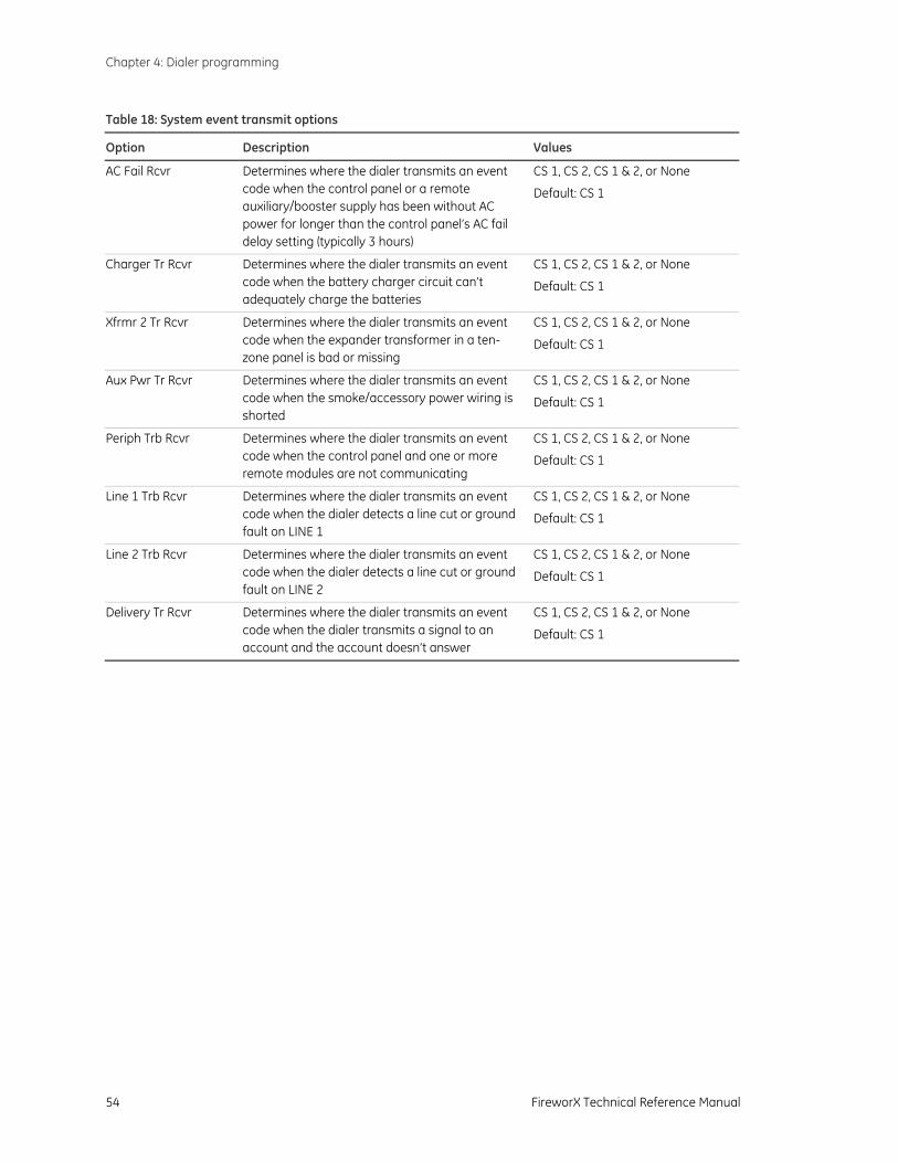
Chapter 4: Dialer programming
54 FireworX Technical Reference Manual
Table 18: System event transmit options
Option Description Values
AC Fail Rcvr Determines where the dialer transmits an event code when the control panel or a remote auxiliary/booster supply has been without AC power for longer than the control panel’s AC fail delay setting (typically 3 hours)
CS 1, CS 2, CS 1 & 2, or None
Default: CS 1
Charger Tr Rcvr Determines where the dialer transmits an event code when the battery charger circuit can’t adequately charge the batteries
CS 1, CS 2, CS 1 & 2, or None
Default: CS 1
Xfrmr 2 Tr Rcvr Determines where the dialer transmits an event code when the expander transformer in a ten-zone panel is bad or missing
CS 1, CS 2, CS 1 & 2, or None
Default: CS 1
Aux Pwr Tr Rcvr Determines where the dialer transmits an event code when the smoke/accessory power wiring is shorted
CS 1, CS 2, CS 1 & 2, or None
Default: CS 1
Periph Trb Rcvr Determines where the dialer transmits an event code when the control panel and one or more remote modules are not communicating
CS 1, CS 2, CS 1 & 2, or None
Default: CS 1
Line 1 Trb Rcvr Determines where the dialer transmits an event code when the dialer detects a line cut or ground fault on LINE 1
CS 1, CS 2, CS 1 & 2, or None
Default: CS 1
Line 2 Trb Rcvr Determines where the dialer transmits an event code when the dialer detects a line cut or ground fault on LINE 2
CS 1, CS 2, CS 1 & 2, or None
Default: CS 1
Delivery Tr Rcvr Determines where the dialer transmits an event code when the dialer transmits a signal to an account and the account doesn’t answer
CS 1, CS 2, CS 1 & 2, or None
Default: CS 1
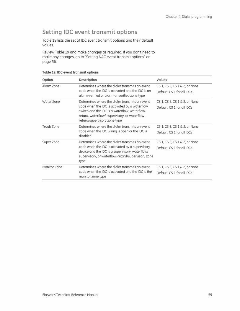
Chapter 4: Dialer programming
FireworX Technical Reference Manual 55
Setting IDC event transmit options Table 19 lists the set of IDC event transmit options and their default values.
Review Table 19 and make changes as required. If you don’t need to make any changes, go to “Setting NAC event transmit options“ on page 56. Table 19: IDC event transmit options
Option Description Values
Alarm Zone Determines where the dialer transmits an event code when the IDC is activated and the IDC is an alarm-verified or alarm-unverified zone type
CS 1, CS 2, CS 1 & 2, or None
Default: CS 1 for all IDCs
Water Zone Determines where the dialer transmits an event code when the IDC is activated by a waterflow switch and the IDC is a waterflow, waterflow-retard, waterflow/ supervisory, or waterflow-retard/supervisory zone type
CS 1, CS 2, CS 1 & 2, or None
Default: CS 1 for all IDCs
Troub Zone Determines where the dialer transmits an event code when the IDC wiring is open or the IDC is disabled
CS 1, CS 2, CS 1 & 2, or None
Default: CS 1 for all IDCs
Super Zone Determines where the dialer transmits an event code when the IDC is activated by a supervisory device and the IDC is a supervisory, waterflow/ supervisory, or waterflow-retard/supervisory zone type
CS 1, CS 2, CS 1 & 2, or None
Default: CS 1 for all IDCs
Monitor Zone Determines where the dialer transmits an event code when the IDC is activated and the IDC is the monitor zone type
CS 1, CS 2, CS 1 & 2, or None
Default: CS 1 for all IDCs
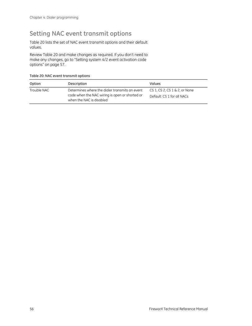
Chapter 4: Dialer programming
56 FireworX Technical Reference Manual
Setting NAC event transmit options Table 20 lists the set of NAC event transmit options and their default values.
Review Table 20 and make changes as required. If you don’t need to make any changes, go to “Setting system 4/2 event activation code options“ on page 57. Table 20: NAC event transmit options
Option Description Values
Trouble NAC Determines where the dialer transmits an event code when the NAC wiring is open or shorted or when the NAC is disabled
CS 1, CS 2, CS 1 & 2, or None
Default: CS 1 for all NACs
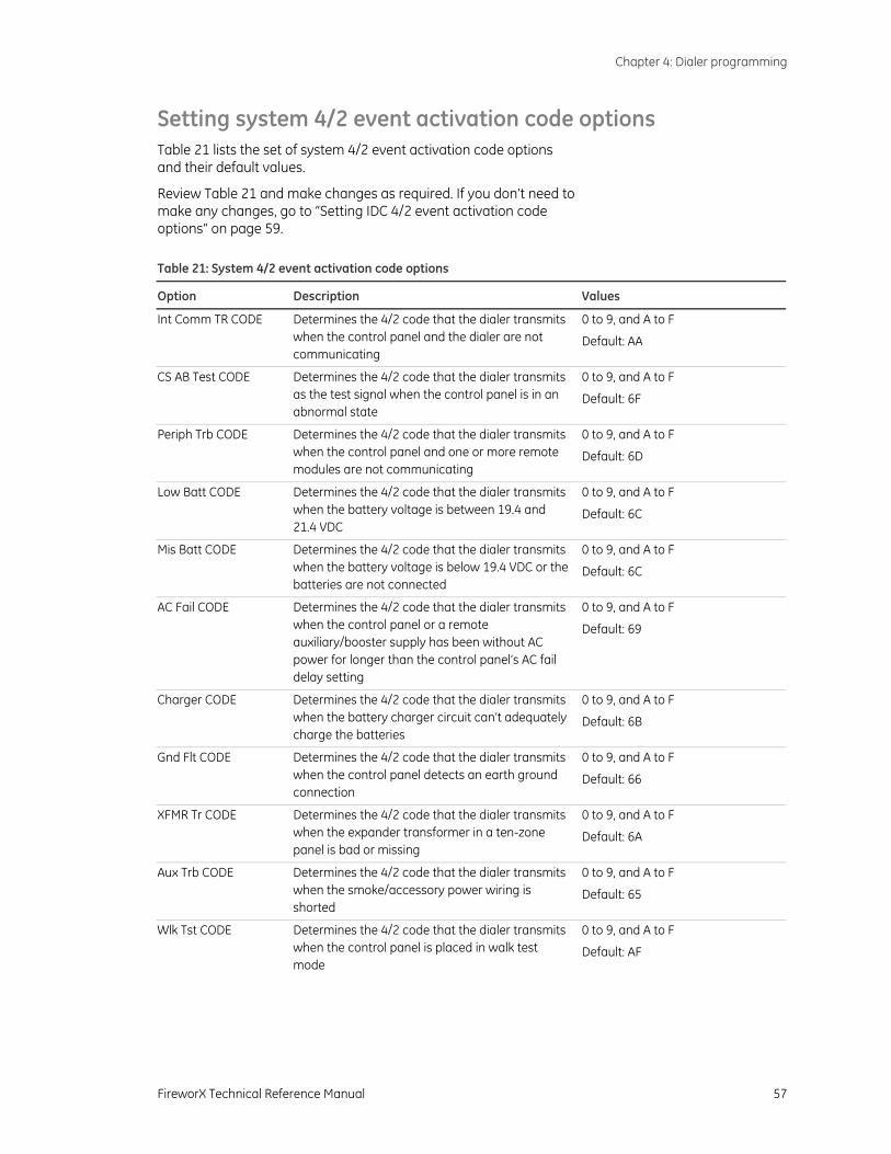
Chapter 4: Dialer programming
FireworX Technical Reference Manual 57
Setting system 4/2 event activation code options Table 21 lists the set of system 4/2 event activation code options and their default values.
Review Table 21 and make changes as required. If you don’t need to make any changes, go to “Setting IDC 4/2 event activation code options“ on page 59. Table 21: System 4/2 event activation code options
Option Description Values
Int Comm TR CODE Determines the 4/2 code that the dialer transmits when the control panel and the dialer are not communicating
0 to 9, and A to F
Default: AA
CS AB Test CODE Determines the 4/2 code that the dialer transmits as the test signal when the control panel is in an abnormal state
0 to 9, and A to F
Default: 6F
Periph Trb CODE Determines the 4/2 code that the dialer transmits when the control panel and one or more remote modules are not communicating
0 to 9, and A to F
Default: 6D
Low Batt CODE Determines the 4/2 code that the dialer transmits when the battery voltage is between 19.4 and 21.4 VDC
0 to 9, and A to F
Default: 6C
Mis Batt CODE Determines the 4/2 code that the dialer transmits when the battery voltage is below 19.4 VDC or the batteries are not connected
0 to 9, and A to F
Default: 6C
AC Fail CODE Determines the 4/2 code that the dialer transmits when the control panel or a remote auxiliary/booster supply has been without AC power for longer than the control panel’s AC fail delay setting
0 to 9, and A to F
Default: 69
Charger CODE Determines the 4/2 code that the dialer transmits when the battery charger circuit can’t adequately charge the batteries
0 to 9, and A to F
Default: 6B
Gnd Flt CODE Determines the 4/2 code that the dialer transmits when the control panel detects an earth ground connection
0 to 9, and A to F
Default: 66
XFMR Tr CODE Determines the 4/2 code that the dialer transmits when the expander transformer in a ten-zone panel is bad or missing
0 to 9, and A to F
Default: 6A
Aux Trb CODE Determines the 4/2 code that the dialer transmits when the smoke/accessory power wiring is shorted
0 to 9, and A to F
Default: 65
Wlk Tst CODE Determines the 4/2 code that the dialer transmits when the control panel is placed in walk test mode
0 to 9, and A to F
Default: AF
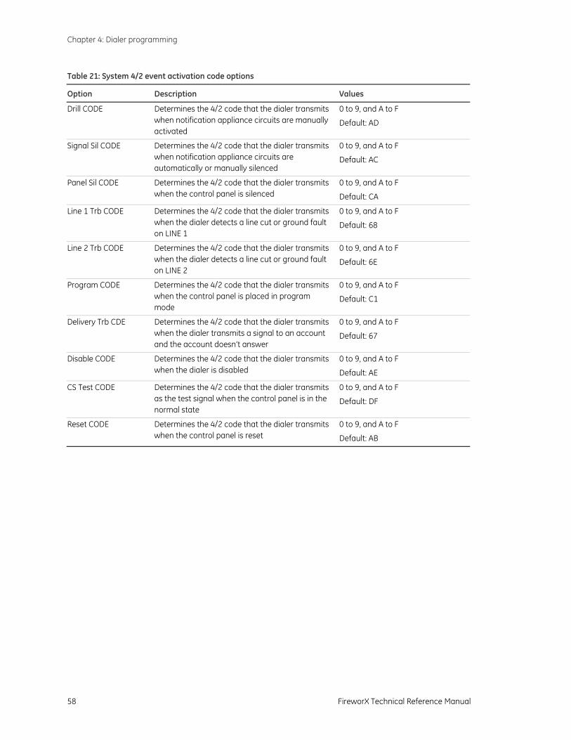
Chapter 4: Dialer programming
58 FireworX Technical Reference Manual
Table 21: System 4/2 event activation code options
Option Description Values
Drill CODE Determines the 4/2 code that the dialer transmits when notification appliance circuits are manually activated
0 to 9, and A to F
Default: AD
Signal Sil CODE Determines the 4/2 code that the dialer transmits when notification appliance circuits are automatically or manually silenced
0 to 9, and A to F
Default: AC
Panel Sil CODE Determines the 4/2 code that the dialer transmits when the control panel is silenced
0 to 9, and A to F
Default: CA
Line 1 Trb CODE Determines the 4/2 code that the dialer transmits when the dialer detects a line cut or ground fault on LINE 1
0 to 9, and A to F
Default: 68
Line 2 Trb CODE Determines the 4/2 code that the dialer transmits when the dialer detects a line cut or ground fault on LINE 2
0 to 9, and A to F
Default: 6E
Program CODE Determines the 4/2 code that the dialer transmits when the control panel is placed in program mode
0 to 9, and A to F
Default: C1
Delivery Trb CDE Determines the 4/2 code that the dialer transmits when the dialer transmits a signal to an account and the account doesn’t answer
0 to 9, and A to F
Default: 67
Disable CODE Determines the 4/2 code that the dialer transmits when the dialer is disabled
0 to 9, and A to F
Default: AE
CS Test CODE Determines the 4/2 code that the dialer transmits as the test signal when the control panel is in the normal state
0 to 9, and A to F
Default: DF
Reset CODE Determines the 4/2 code that the dialer transmits when the control panel is reset
0 to 9, and A to F
Default: AB
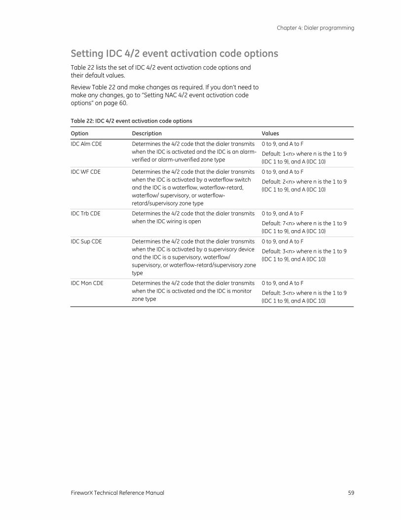
Chapter 4: Dialer programming
FireworX Technical Reference Manual 59
Setting IDC 4/2 event activation code options Table 22 lists the set of IDC 4/2 event activation code options and their default values.
Review Table 22 and make changes as required. If you don’t need to make any changes, go to “Setting NAC 4/2 event activation code options“ on page 60. Table 22: IDC 4/2 event activation code options
Option Description Values
IDC Alm CDE Determines the 4/2 code that the dialer transmits when the IDC is activated and the IDC is an alarm-verified or alarm-unverified zone type
0 to 9, and A to F
Default: 1<n> where n is the 1 to 9 (IDC 1 to 9), and A (IDC 10)
IDC WF CDE Determines the 4/2 code that the dialer transmits when the IDC is activated by a waterflow switch and the IDC is a waterflow, waterflow-retard, waterflow/ supervisory, or waterflow-retard/supervisory zone type
0 to 9, and A to F
Default: 2<n> where n is the 1 to 9 (IDC 1 to 9), and A (IDC 10)
IDC Trb CDE Determines the 4/2 code that the dialer transmits when the IDC wiring is open
0 to 9, and A to F
Default: 7<n> where n is the 1 to 9 (IDC 1 to 9), and A (IDC 10)
IDC Sup CDE Determines the 4/2 code that the dialer transmits when the IDC is activated by a supervisory device and the IDC is a supervisory, waterflow/ supervisory, or waterflow-retard/supervisory zone type
0 to 9, and A to F
Default: 3<n> where n is the 1 to 9 (IDC 1 to 9), and A (IDC 10)
IDC Mon CDE Determines the 4/2 code that the dialer transmits when the IDC is activated and the IDC is monitor zone type
0 to 9, and A to F
Default: 3<n> where n is the 1 to 9 (IDC 1 to 9), and A (IDC 10)
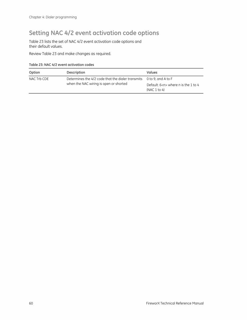
Chapter 4: Dialer programming
60 FireworX Technical Reference Manual
Setting NAC 4/2 event activation code options Table 23 lists the set of NAC 4/2 event activation code options and their default values.
Review Table 23 and make changes as required. Table 23: NAC 4/2 event activation codes
Option Description Values
NAC Trb CDE Determines the 4/2 code that the dialer transmits when the NAC wiring is open or shorted
0 to 9, and A to F
Default: 6<n> where n is the 1 to 4 (NAC 1 to 4)
Chapter 4: Dialer programming
FireworX Technical Reference Manual 61
Restoring dialer default settings Dialers are shipped from the factory with default settings for a typical system. You can restore the default settings at any time.
To restore dialer default settings:
1. Press Reset and select Yes.
2. Press Panel Silence to save and advance to the next program option.
The trouble buzzer sounds a long beep as confirmation.

Chapter 4: Dialer programming
62 FireworX Technical Reference Manual
FireworX Technical Reference Manual 63
Chapter 5 Maintenance
Summary
This chapter provides instructions for maintaining the control panel, performing walk tests, and clearing trouble messages. It is intended for those trained and authorized to maintain the fire alarm system.
Content
Preventive maintenance • 64 Preventive maintenance schedule • 64 Canadian tests for grounds, opens, and shorts • 64
Performing a walk test • 66 Performing lamp tests • 68
Panel lamp test • 68 FSRSI, FSRZI-A, and FSRZI-SA lamp test • 68
Trouble messages • 69 Replacing the control panel fuse • 70 Replacement parts • 71
Chapter 5: Maintenance
64 FireworX Technical Reference Manual
Preventive maintenance Before commencing testing, notify all areas where the alarm sounds and off-premises locations that receive alarm and trouble transmissions that testing is in progress.
Records of all testing and maintenance must be kept as required by the authority having jurisdiction.
Required tools:
• Slotted screwdriver, insulated • Digital multimeter • 1.1 kΩ, 1 W resistor • 12 in (30.5 cm) jumper lead with alligator clips • Panel door key • Sound-level meter
A complete check of installed field wiring and devices should be made at regular intervals in accordance with NFPA 72, Canadian Electrical Code Part I, ULC S524, and ULC S536 requirements. This includes testing all alarm and supervisory initiating devices and circuits and any off-premises connections.
Panel operation should be verified in the alarm, supervisory, and trouble modes.
To ensure that the panel can operate correctly when primary power is lost, the batteries should be inspected and tested periodically. Batteries should be replaced (at a minimum) every four years.
Preventive maintenance schedule
Refer to NFPA 72, Canadian Electrical Code Part I, ULC S524, or ULC S536 for more information on required inspection and testing methods and frequency of fire alarm systems and devices. For detector sensitivity and functionality testing, refer to the detector manufacturer’s installation instructions.
Canadian tests for grounds, opens, and shorts ULC requires that you test ground fault, open circuit, and short circuit indications.
For ground fault tests, short one leg of the circuit to chassis ground and verify that the system Ground Fault LED and Trouble LEDs turn on.
For NAC and IDC open circuit tests, remove the end-of-line resistor from the last device on the circuit and verify that the system Trouble LED and the circuit’s trouble (TBL) LED turn on.
For NAC short circuit testing, place a short across the NAC output terminals and verify that the system Trouble LED and the circuit’s trouble (TBL) LED turn on.

Chapter 5: Maintenance
FireworX Technical Reference Manual 65
For AUX power short circuit testing, place a short across the AUX power output’s plus (+) and minus (−) terminals and verify that the system Trouble LED turns on.
For communications testing, place a short across C+ and C− and verify that the system Trouble LED and Annun Trouble LED turn on.
Caution: Do not place the short across the 24VAC IN terminals.
Chapter 5: Maintenance
66 FireworX Technical Reference Manual
Performing a walk test A walk test lets you test initiating device circuits (IDCs) without having to create an actual alarm condition. IDCs should be placed in walk test one at a time. This allows the rest of the system to remain in service. Walk test will not operate with an active alarm or supervisory event at the panel.
You can conduct a walk test in silent or audible mode. In silent mode, the audible devices (NACs) do not sound. In audible mode, the NACs sound for a number of times equal to the zone number. Example: three times for IDC 3.
In a walk test, the panel responds to the first signal it receives and ignores all others on that IDC until it clears that signal or the panel is reset. The input must be restored to the normal state before the next input is tested. When the input is restored, the panel automatically resets the circuit being tested. The automatic reset takes eight seconds. After the circuit is reset, the next device can be tested.
The panel terminates the walk test if:
• A zone other than the zone being tested is activated
• There are 30 minutes of inactivity on the zone being tested
• The panel is reset
• The Walk Test button is pressed a third time
When you press Walk Test:
• The Walk Test LED turns on or flashes depending if you selected a silent or audible walk test, respectively
• The panel enters the trouble state
• There is no fire protection for the IDC in walk test
If an unselected IDC goes into alarm or trouble, all outputs operate as programmed.
The IDC you are testing behaves as follows:
• The appropriate panel, FSRSI, and FSRZI-A LEDs and buzzers are turned on.
• In the audible test mode, the notification appliances sound for a number of times equal to the zone number.
• After activation, the panel resets the IDC. During the reset period (approximately eight seconds), the IDC trouble LED flashes rapidly. If the device being tested is not restored, the IDC does not reset and the LED continues to flash. If the device is restored (no alarm is present), the panel is ready to test another device or detector.
• Resettable auxiliary power is deactivated while the zone is reset.
WARNING: If you cancel a walk test with a device in the active state, the control panel will activate the programmed responses for that device. Do not cancel a walk test when the Trouble LED for the IDC under test is flashing rapidly.
Chapter 5: Maintenance
FireworX Technical Reference Manual 67
• Input zones programmed as waterflow with retard require 10 to 15 seconds of activation to initiate the test signals.
• For trouble events, the appropriate LEDs and the buzzers are turned on. In the audible (NAC) test mode a one-second pulse sounds on the audible devices. After sounding, the zone resets in preparation for continued testing.
• For ground fault events, the appropriate LEDs and the buzzers are turned on. In the audible (NAC) test mode a one-second pulse sounds on the audible devices. After sounding, the zone resets in preparation for continued testing.
To perform a walk test:
1. Press the Walk Test button once to perform an audible walk test.
— or —
Press the Walk Test button twice to perform a silent walk test.
2. Press the Disable button for the IDC you want to test.
3. Conduct your walk test for the IDC.
4. When you are finished testing an IDC, press the Disable button to turn off the walk test for that IDC.
5. Select another IDC to walk test (steps 2 through 4) or exit from the walk test by pressing the Walk Test button.
Chapter 5: Maintenance
68 FireworX Technical Reference Manual
Performing lamp tests
Panel lamp test
A panel lamp test turns on all the LEDs on the panel and on FSRSI, FSRZI-A, and FSRZI-SA modules so you can verify their proper operation.
To test panel LEDs:
1. Press and hold the Remote Disconnect and Walk Test buttons simultaneously.
2. Verify that all LEDs on the panel turn on.
If a dialer is installed, the LCD displays:
DB# xx P:x.yy.zz
D:x.yy.zz
Where:
DB# is the database revision number
P:x.yy.zz is the main panel version
D:x.yy.zz is the F-DACT(F) version
FSRSI, FSRZI-A, and FSRZI-SA lamp test FSRSI, FSRZI-A, and FSRZI-SA modules can be installed individually or in groups to create a complete remote annunciator. You can perform a local lamp test on the FSRSI, FSRZI-A, and FSRZI-SA. An FSRSI is required to initiate this function.
To test FSRSI and FSRZI-A LEDs:
1. Press and hold the FSRSI Silence button for five seconds.
2. Verify that all LEDs on the FSRSI and FSRZI-A modules turn on.

Chapter 5: Maintenance
FireworX Technical Reference Manual 69
Trouble messages Table 24: Possible causes of trouble messages
Message Possible cause
Peripheral trouble The panel lost communications with the peripherals.
Battery Bad The battery is bad and needs to be replaced.
Battery Missing The battery is no longer connected.
AC Failure The panel lost AC power.
Charger Trouble The panel detected a battery charger trouble condition. The charger may not be able to charge the batteries.
Ground Fault The panel detected a ground fault.
Transformer 2 TR The panel detected a trouble condition in the Power Expander Transformer.
AUX Power Troub The panel detected a trouble condition in the AUX power circuit.
Internal Comm TR There panel lost communications with an F-DACT(F).
RRM(s) disabled One or more FSRRM24s are disabled.
Dialing... The F-DACT(F) is dialing a DACR.
DACT Configuration TRBL The F-DACT(F) is not programmed or has unverified changes.
DACT Delivery TR The F-DACT(F) failed to deliver a message to the receiver or CMS.
DACT Line 1 Trbl A ground fault or line fault has been detected on Line 1 of the F-DACT(F).
DACT Line 2 Trbl A ground fault or line fault has been detected on Line 2 of the F-DACT(F).
Note: If the Disabled and Annunc Trouble LEDs are on, and all IDC and NAC Disabled LEDs are off, then the FSRRM24 is disabled.
Chapter 5: Maintenance
70 FireworX Technical Reference Manual
Replacing the control panel fuse The control panel is protected with a 5 A fuse. The fuse is part of the AC terminal block located inside the control panel.
To replace the fuse:
1. Disconnect the standby batteries, then switch off the circuit breaker that supplies mains AC power to the control panel.
2. Open the cabinet door, then remove the terminal block cover from its slot to expose the AC terminal block.
3. Unplug the fuse holder and replace the existing fuse with a new fuse of the same type and size.
4. Plug the fuse holder into the AC terminal block and insert the terminal block cover into its slot.
5. Switch on the circuit breaker that supplies mains AC power to the control panel then connect the standby batteries.
WARNING: High voltage capable of causing personal injury or death may be present. Make sure all sources of power are removed from the panel before replacing the fuse.
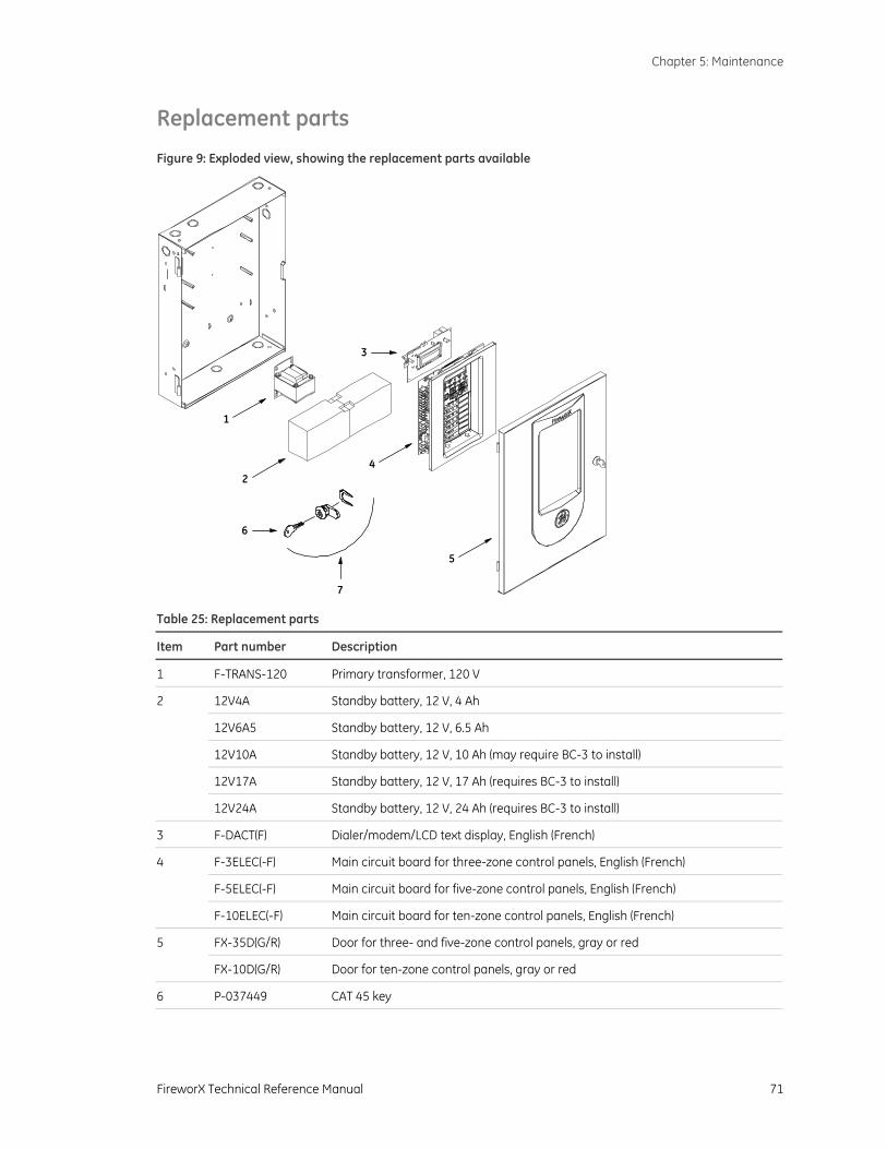
Chapter 5: Maintenance
FireworX Technical Reference Manual 71
Replacement parts
Figure 9: Exploded view, showing the replacement parts available
1
3
7
24
6
5
Table 25: Replacement parts
Item Part number Description
1 F-TRANS-120 Primary transformer, 120 V
2 12V4A Standby battery, 12 V, 4 Ah
12V6A5 Standby battery, 12 V, 6.5 Ah
12V10A Standby battery, 12 V, 10 Ah (may require BC-3 to install)
12V17A Standby battery, 12 V, 17 Ah (requires BC-3 to install)
12V24A Standby battery, 12 V, 24 Ah (requires BC-3 to install)
3 F-DACT(F) Dialer/modem/LCD text display, English (French)
4 F-3ELEC(-F) Main circuit board for three-zone control panels, English (French)
F-5ELEC(-F) Main circuit board for five-zone control panels, English (French)
F-10ELEC(-F) Main circuit board for ten-zone control panels, English (French)
5 FX-35D(G/R) Door for three- and five-zone control panels, gray or red
FX-10D(G/R) Door for ten-zone control panels, gray or red
6 P-037449 CAT 45 key
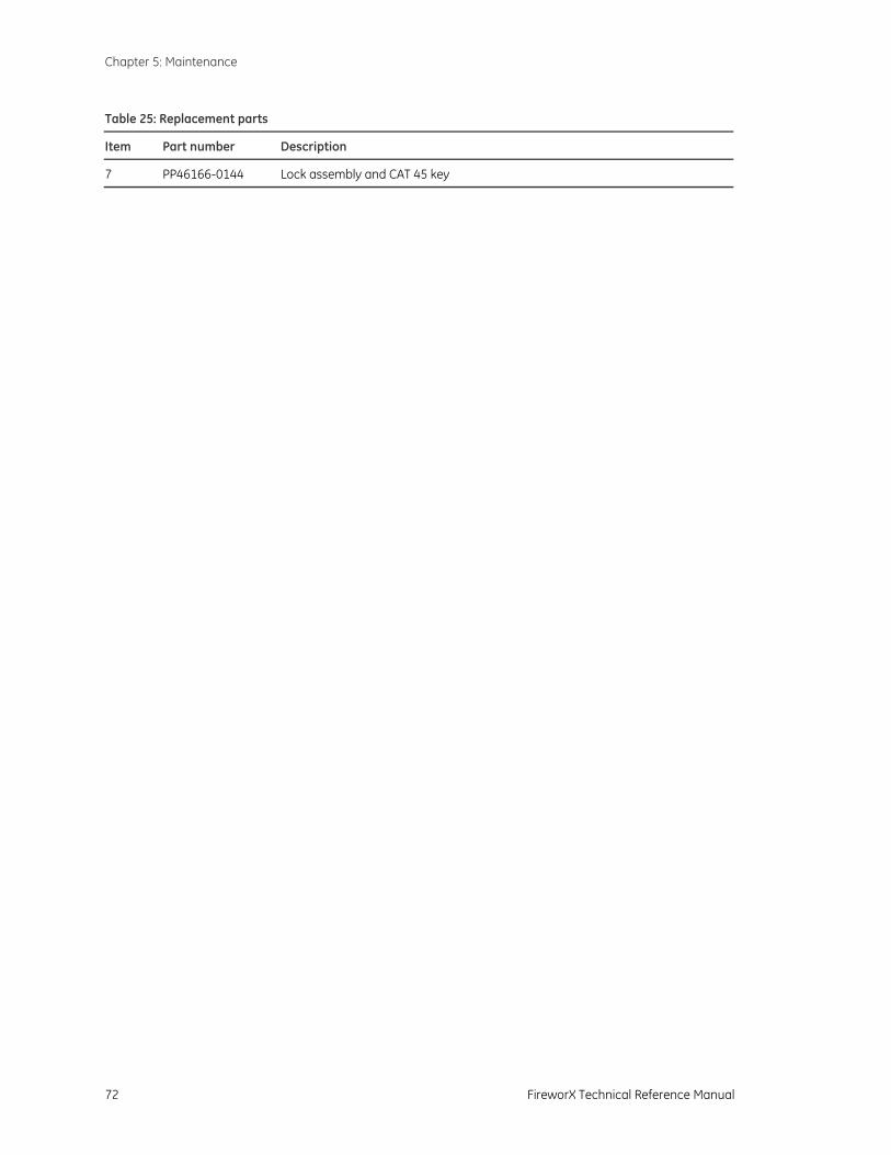
Chapter 5: Maintenance
72 FireworX Technical Reference Manual
Table 25: Replacement parts
Item Part number Description
7 PP46166-0144 Lock assembly and CAT 45 key
FireworX Technical Reference Manual 73
Appendix A System calculations
Summary
This appendix provides worksheets for sizing standby batteries and for calculating the maximum wire lengths of notification appliance circuits (NACs).
Content
Battery calculation worksheet • 74 Notification appliance voltage drop calculation • 77 Notification appliance circuit calculations • 79
Introduction • 79 What you’ll need • 79 Worksheet method • 80 Equation method • 82
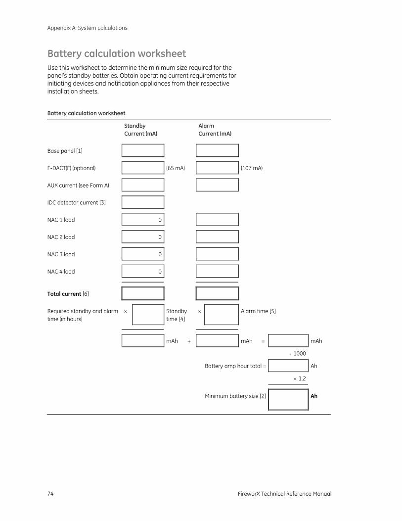
Appendix A: System calculations
74 FireworX Technical Reference Manual
Battery calculation worksheet Use this worksheet to determine the minimum size required for the panel’s standby batteries. Obtain operating current requirements for initiating devices and notification appliances from their respective installation sheets.
Battery calculation worksheet
Standby Current (mA)
Alarm Current (mA)
Base panel [1]
F-DACT(F) (optional) (65 mA) (107 mA)
AUX current (see Form A)
IDC detector current [3]
NAC 1 load 0
NAC 2 load 0
NAC 3 load 0
NAC 4 load 0
Total current [6]
Required standby and alarm time (in hours)
× Standby time [4]
× Alarm time [5]
mAh + mAh = mAh
÷ 1000
Battery amp hour total = Ah
× 1.2
Minimum battery size [2]
Ah
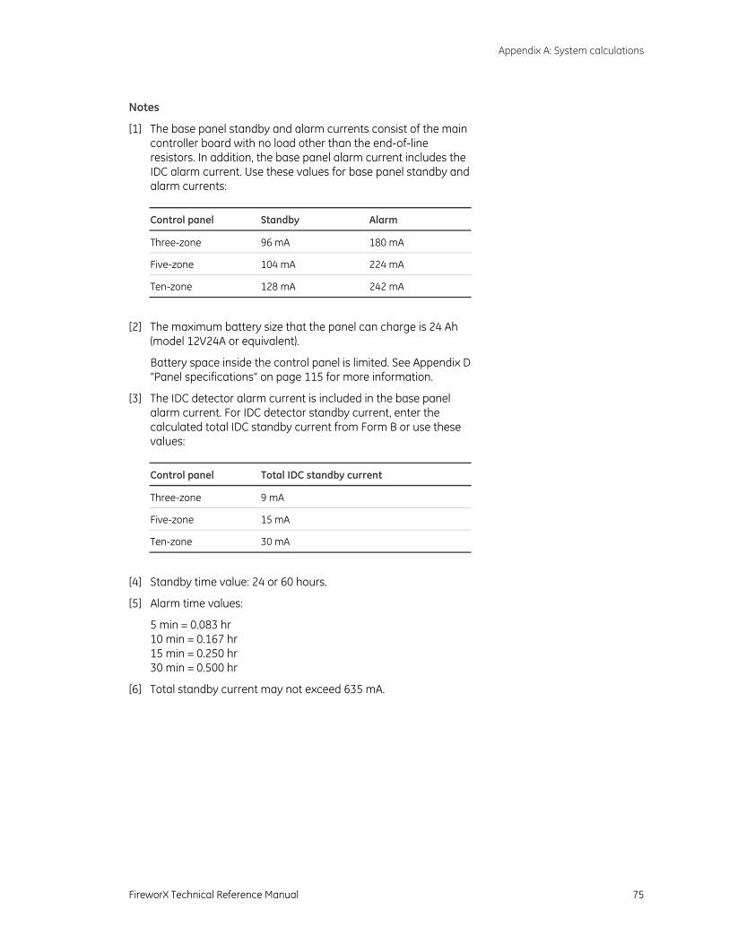
Appendix A: System calculations
FireworX Technical Reference Manual 75
Notes
[1] The base panel standby and alarm currents consist of the main controller board with no load other than the end-of-line resistors. In addition, the base panel alarm current includes the IDC alarm current. Use these values for base panel standby and alarm currents:
Control panel Standby Alarm
Three-zone 96 mA 180 mA
Five-zone 104 mA 224 mA
Ten-zone 128 mA 242 mA
[2] The maximum battery size that the panel can charge is 24 Ah (model 12V24A or equivalent).
Battery space inside the control panel is limited. See Appendix D “Panel specifications“ on page 115 for more information.
[3] The IDC detector alarm current is included in the base panel alarm current. For IDC detector standby current, enter the calculated total IDC standby current from Form B or use these values:
Control panel Total IDC standby current
Three-zone 9 mA
Five-zone 15 mA
Ten-zone 30 mA
[4] Standby time value: 24 or 60 hours.
[5] Alarm time values:
5 min = 0.083 hr 10 min = 0.167 hr 15 min = 0.250 hr 30 min = 0.500 hr
[6] Total standby current may not exceed 635 mA.
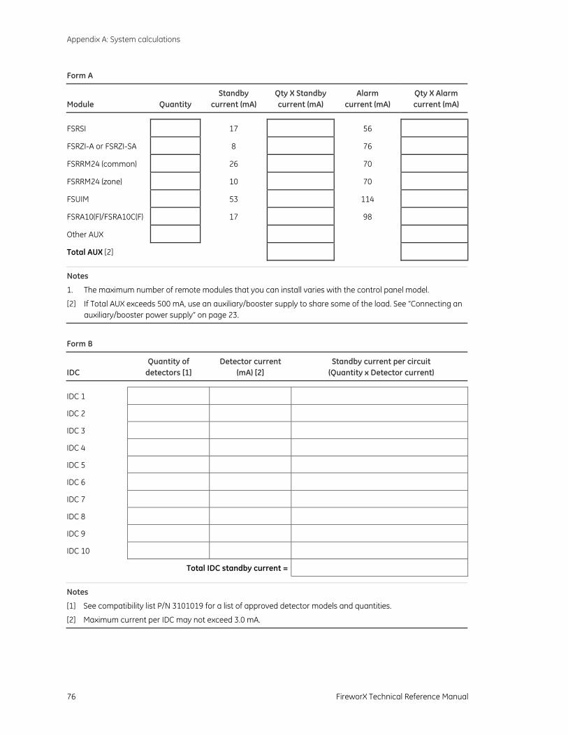
Appendix A: System calculations
76 FireworX Technical Reference Manual
Form A
Module
Quantity
Standby current (mA)
Qty X Standby current (mA)
Alarm current (mA)
Qty X Alarm current (mA)
FSRSI 17 56
FSRZI-A or FSRZI-SA 8 76
FSRRM24 (common) 26 70
FSRRM24 (zone) 10 70
FSUIM 53 114
FSRA10(F)/FSRA10C(F) 17 98
Other AUX
Total AUX [2]
Notes
1. The maximum number of remote modules that you can install varies with the control panel model.
[2] If Total AUX exceeds 500 mA, use an auxiliary/booster supply to share some of the load. See “Connecting an auxiliary/booster power supply“ on page 23.
Form B
IDC
Quantity of detectors [1]
Detector current (mA) [2]
Standby current per circuit (Quantity x Detector current)
IDC 1
IDC 2
IDC 3
IDC 4
IDC 5
IDC 6
IDC 7
IDC 8
IDC 9
IDC 10
Total IDC standby current =
Notes
[1] See compatibility list P/N 3101019 for a list of approved detector models and quantities.
[2] Maximum current per IDC may not exceed 3.0 mA.
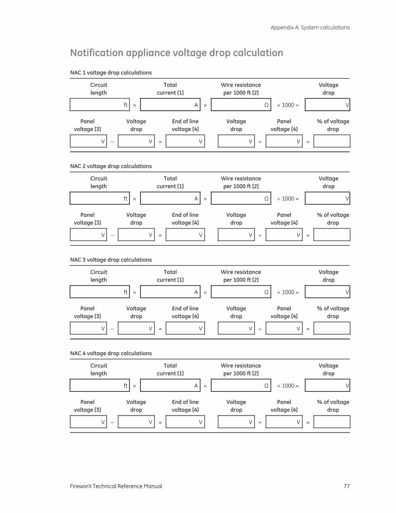
Appendix A: System calculations
FireworX Technical Reference Manual 77
Notification appliance voltage drop calculation NAC 1 voltage drop calculations
Circuit length
Total current [1]
Wire resistance per 1000 ft [2]
Voltage drop
ft × A × Ω ÷ 1000 = V
Panel voltage [3]
Voltage drop
End of line voltage [4]
Voltage drop
Panel voltage [4]
% of voltage drop
V − V = V V ÷ V =
NAC 2 voltage drop calculations
Circuit length
Total current [1]
Wire resistance per 1000 ft [2]
Voltage drop
ft × A × Ω ÷ 1000 = V
Panel voltage [3]
Voltage drop
End of line voltage [4]
Voltage drop
Panel voltage [4]
% of voltage drop
V − V = V V ÷ V =
NAC 3 voltage drop calculations
Circuit length
Total current [1]
Wire resistance per 1000 ft [2]
Voltage drop
ft × A × Ω ÷ 1000 = V
Panel voltage [3]
Voltage drop
End of line voltage [4]
Voltage drop
Panel voltage [4]
% of voltage drop
V − V = V V ÷ V =
NAC 4 voltage drop calculations
Circuit length
Total current [1]
Wire resistance per 1000 ft [2]
Voltage drop
ft × A × Ω ÷ 1000 = V
Panel voltage [3]
Voltage drop
End of line voltage [4]
Voltage drop
Panel voltage [4]
% of voltage drop
V − V = V V ÷ V =
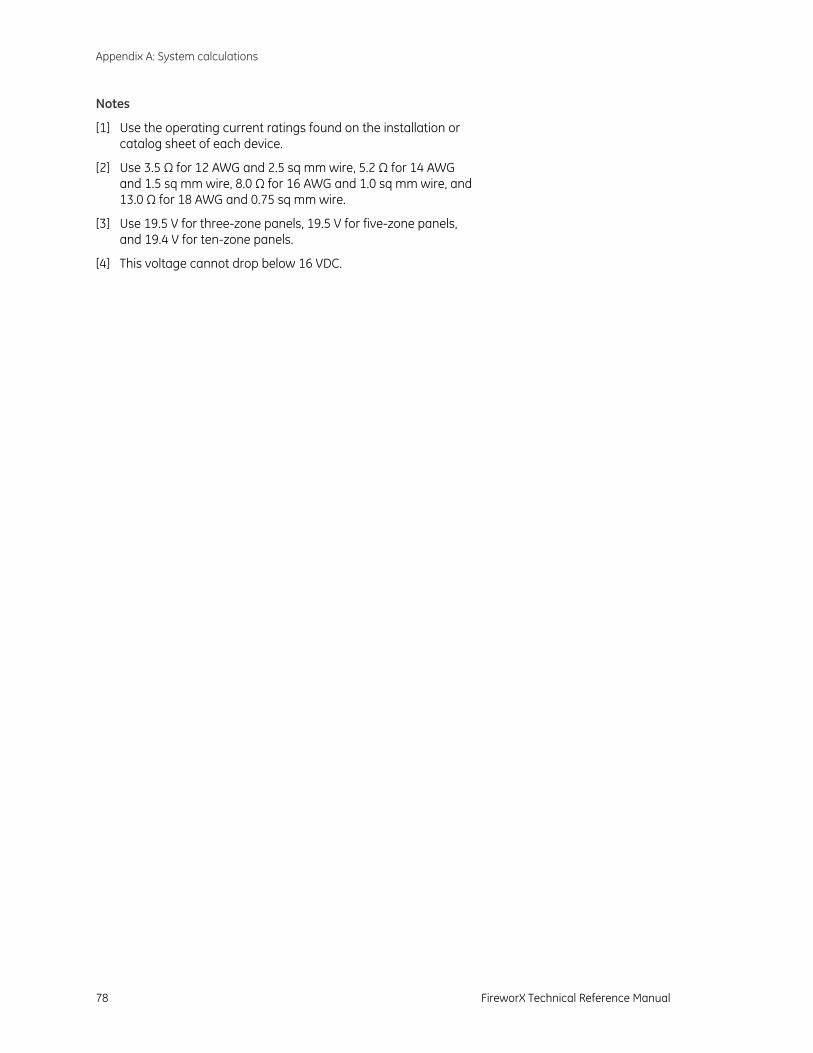
Appendix A: System calculations
78 FireworX Technical Reference Manual
Notes
[1] Use the operating current ratings found on the installation or catalog sheet of each device.
[2] Use 3.5 Ω for 12 AWG and 2.5 sq mm wire, 5.2 Ω for 14 AWG and 1.5 sq mm wire, 8.0 Ω for 16 AWG and 1.0 sq mm wire, and 13.0 Ω for 18 AWG and 0.75 sq mm wire.
[3] Use 19.5 V for three-zone panels, 19.5 V for five-zone panels, and 19.4 V for ten-zone panels.
[4] This voltage cannot drop below 16 VDC.
Appendix A: System calculations
FireworX Technical Reference Manual 79
Notification appliance circuit calculations
Introduction
This topic shows you how to determine the maximum cable length of a notification appliance circuit (NAC) for a given number of appliances.
Two methods are presented: worksheet and equation. The worksheet method is simpler, but your installation must meet the criteria listed on the worksheet. If your installation does not meet these criteria, you need to use the equation method.
The methods given here determine cable lengths that work under all operating conditions. The calculations ensure that the required operating voltage and current will be supplied to all notification appliances. To do this, we assume these two worst-case conditions:
• The voltage at the NAC terminals is the minimum provided by the power supply.
• The notification appliances are clustered at the end of the NAC cable.
Other, more detailed methods that distribute the appliance load along the NAC cable may indicate longer cable runs.
What you’ll need
Appliance and cable values
Whether you use the worksheet method or the equation method, you’ll need to know:
• The minimum operating voltage required for the appliances
• The maximum operating current drawn by each appliance
• The resistance per unit length of the wire used (Ω/ft)
This information can be found on the appliance installation sheets and on the cable specification sheet.
Power supply values
For either method, you’ll need some fixed or calculated operating values for your specific power supply. The fixed values are:
• Source voltage = 20.4 V
• Load factor = 0.25 A/V for three-zone panels, 0.40A/V for five-zone panels, and 0.20 A/V for ten-zone panels
• Power type = FWR
The source voltage is the theoretical operating minimum for the power supply, and is calculated as 85% of 24 volts.
Appendix A: System calculations
80 FireworX Technical Reference Manual
The load factor is a measure of how the power supply voltage reacts when a load is applied. The load factor measures the voltage drop per ampere of current drawn by the load.
The power type reflects the type of power supplied to the NAC terminals at minimum voltage. The current draw of notification appliances can vary substantially with the type of power supplied: full-wave rectified (VFWR) or direct current (VDC). It is important to know the power type at minimum terminal voltage.
You’ll need to calculate the following values relating to your power supply and to the NAC circuit current. These are:
• Minimum voltage
• Voltage drop
The minimum voltage is the lowest voltage measured at the NAC terminals when the power supply is under the maximum load for that circuit (i.e. for the appliances that constitute the NAC).
The voltage drop is the difference between the minimum voltage and 16 V. This value is for use with the worksheet only.
Worksheet method
Use this worksheet to determine the maximum cable length of a notification appliance circuit for a given number of appliances.
Use this worksheet only if all the appliances are regulated. That is, they must have a minimum operating voltage of 16 V. For other appliances, use the “Equation method.”
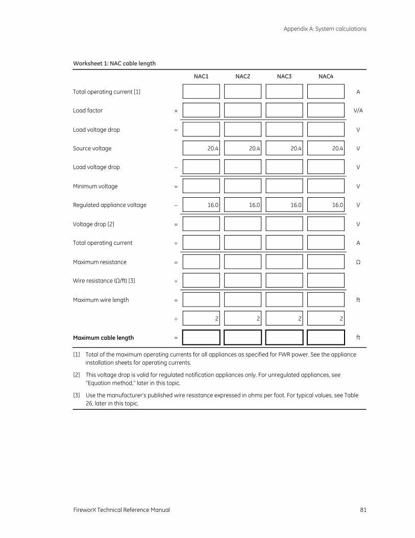
Appendix A: System calculations
FireworX Technical Reference Manual 81
Worksheet 1: NAC cable length
NAC1 NAC2 NAC3 NAC4
Total operating current [1] A
Load factor × V/A
Load voltage drop = V
Source voltage 20.4 20.4 20.4 20.4 V
Load voltage drop − V
Minimum voltage = V
Regulated appliance voltage − 16.0 16.0 16.0 16.0 V
Voltage drop [2] = V
Total operating current ÷ A
Maximum resistance = Ω
Wire resistance (Ω/ft) [3] ÷
Maximum wire length = ft
÷ 2 2 2 2
Maximum cable length = ft
[1] Total of the maximum operating currents for all appliances as specified for FWR power. See the appliance installation sheets for operating currents.
[2] This voltage drop is valid for regulated notification appliances only. For unregulated appliances, see “Equation method,” later in this topic.
[3] Use the manufacturer’s published wire resistance expressed in ohms per foot. For typical values, see Table 26, later in this topic.
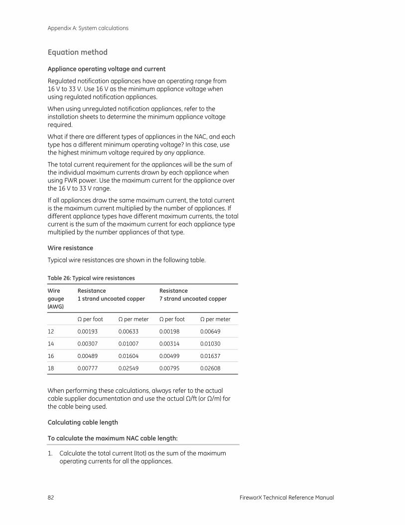
Appendix A: System calculations
82 FireworX Technical Reference Manual
Equation method
Appliance operating voltage and current
Regulated notification appliances have an operating range from 16 V to 33 V. Use 16 V as the minimum appliance voltage when using regulated notification appliances.
When using unregulated notification appliances, refer to the installation sheets to determine the minimum appliance voltage required.
What if there are different types of appliances in the NAC, and each type has a different minimum operating voltage? In this case, use the highest minimum voltage required by any appliance.
The total current requirement for the appliances will be the sum of the individual maximum currents drawn by each appliance when using FWR power. Use the maximum current for the appliance over the 16 V to 33 V range.
If all appliances draw the same maximum current, the total current is the maximum current multiplied by the number of appliances. If different appliance types have different maximum currents, the total current is the sum of the maximum current for each appliance type multiplied by the number appliances of that type.
Wire resistance
Typical wire resistances are shown in the following table. Table 26: Typical wire resistances
Wire gauge (AWG)
Resistance 1 strand uncoated copper
Resistance 7 strand uncoated copper
Ω per foot Ω per meter Ω per foot Ω per meter
12 0.00193 0.00633 0.00198 0.00649
14 0.00307 0.01007 0.00314 0.01030
16 0.00489 0.01604 0.00499 0.01637
18 0.00777 0.02549 0.00795 0.02608
When performing these calculations, always refer to the actual cable supplier documentation and use the actual Ω/ft (or Ω/m) for the cable being used.
Calculating cable length
To calculate the maximum NAC cable length:
1. Calculate the total current (Itot) as the sum of the maximum operating currents for all the appliances.
Appendix A: System calculations
FireworX Technical Reference Manual 83
Itot = ΣIa
Where: Ia = appliance maximum current
See the appliance installation sheets for Ia. Remember to use the maximum operating current specified for FWR power.
2. Calculate the minimum voltage (Vm).
Vm = Vr − (Itot × K)
Where: Vs = source voltage Itot = total current (from above) K = load factor
For the power supply, Vs is 20.4 V and K is 0.25 A/V for three-zone panels, 0.40A/V for five-zone panels, and 0.20 A/V for ten-zone panels
3. Calculate the allowable voltage drop (Vd) between the power supply and the appliances.
Vd = Vm − Va
Where: Vm = minimum voltage (from above) Va = appliance minimum voltage
For regulated notification appliances, Va is 16 V. For unregulated notification appliances, Va is the lowest operating voltage specified on the appliance installation sheet.
4. Calculate the maximum resistance (Rmax) the wire can have.
Rmax = Vd / Itot
Where: Vd = voltage drop Itot = total current
5. Calculate the maximum length of the cable (Lc), based on the maximum resistance allowed, the resistance of the wire, and the number of wires in the cable (two).
Lc = (Rmax / Rw) / 2
Where: Rmax = maximum resistance Rw = wire resistance factor
Example: You’re using regulated notification appliances with a ten-zone control panel. Assume that the maximum operating current for each appliance is 100 mA for FWR power, and that 20 appliances will be placed on the NAC. The cable is 12 AWG wire, and the manufacturer specifies a wire resistance factor of 0.002 Ω/ft.
Itot = ΣIa = 20 × 0.1 A = 2 A
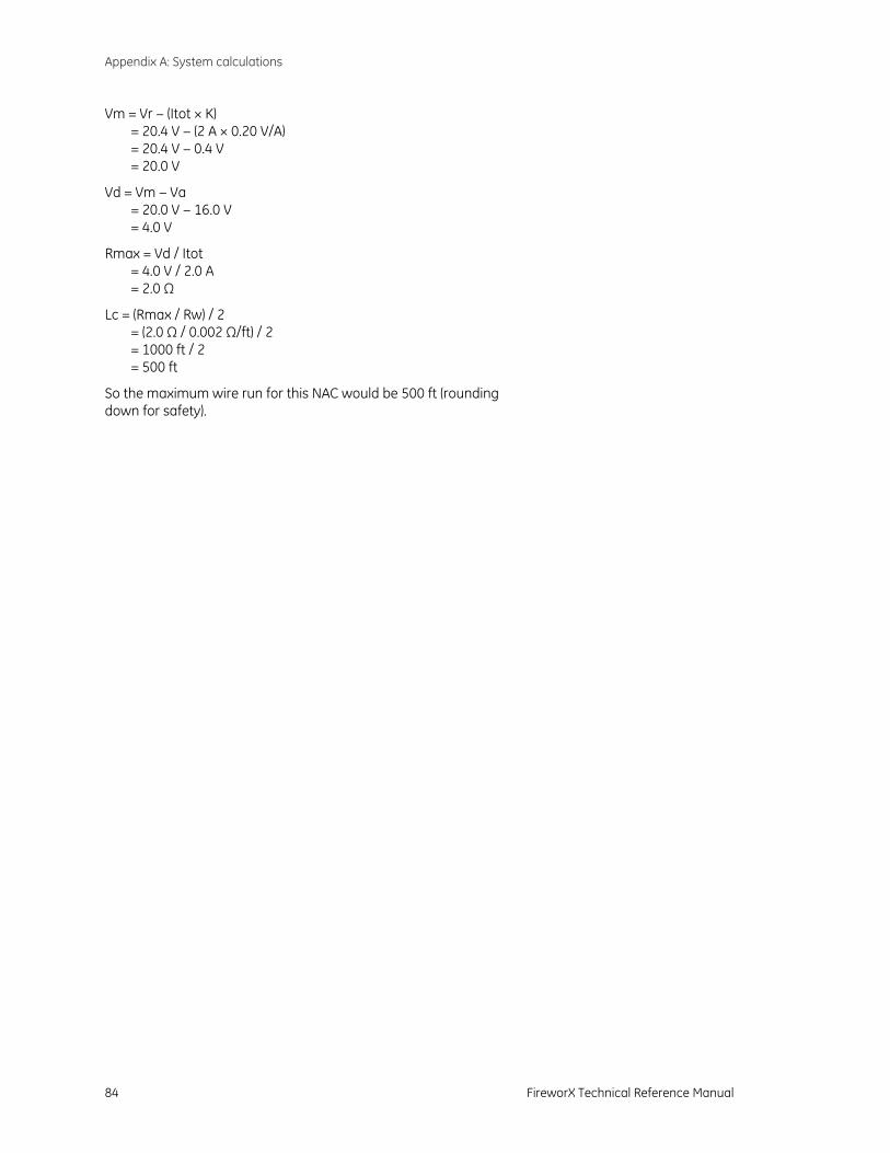
Appendix A: System calculations
84 FireworX Technical Reference Manual
Vm = Vr − (Itot × K) = 20.4 V − (2 A × 0.20 V/A) = 20.4 V − 0.4 V = 20.0 V
Vd = Vm − Va = 20.0 V − 16.0 V = 4.0 V
Rmax = Vd / Itot = 4.0 V / 2.0 A = 2.0 Ω
Lc = (Rmax / Rw) / 2 = (2.0 Ω / 0.002 Ω/ft) / 2 = 1000 ft / 2 = 500 ft
So the maximum wire run for this NAC would be 500 ft (rounding down for safety).

FireworX Technical Reference Manual 85
Appendix B Programming templates
Summary
This appendix provides worksheets to help you program the control panel using the panel’s keypad.
Content
Panel programming worksheet • 86 IDC programming worksheet • 87 NAC programming worksheet • 89 Dialer programming worksheet • 90
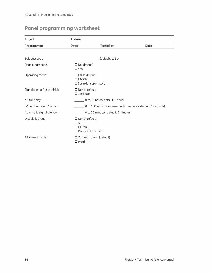
Appendix B: Programming templates
86 FireworX Technical Reference Manual
Panel programming worksheet
Project: Address:
Programmer: Date: Tested by: Date:
Edit passcode (default: 1111)
Enable passcode No (default) Yes
Operating mode: FACP (default) FACOM Sprinkler supervisory
Signal silence/reset inhibit: None (default) 1 minute
AC fail delay: (0 to 15 hours, default: 1 hour)
Waterflow-retard/delay: (0 to 150 seconds in 5-second increments, default: 5 seconds)
Automatic signal silence: (0 to 30 minutes, default: 0 minutes)
Disable lockout: None (default) All IDC/NAC Remote disconnect
RRM multi mode: Common alarm (default) Matrix
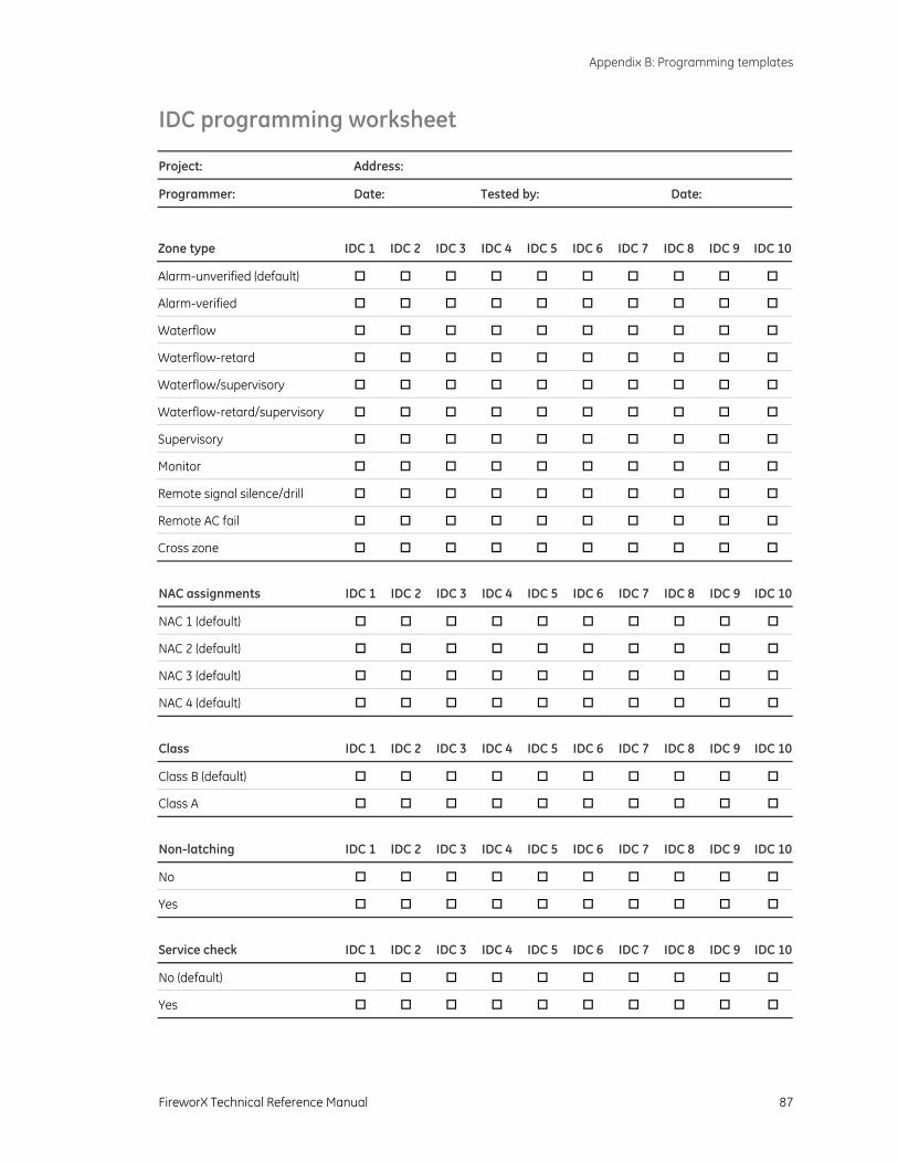
Appendix B: Programming templates
FireworX Technical Reference Manual 87
IDC programming worksheet
Project: Address:
Programmer: Date: Tested by: Date:
Zone type IDC 1 IDC 2 IDC 3 IDC 4 IDC 5 IDC 6 IDC 7 IDC 8 IDC 9 IDC 10
Alarm-unverified (default)
Alarm-verified
Waterflow
Waterflow-retard
Waterflow/supervisory
Waterflow-retard/supervisory
Supervisory
Monitor
Remote signal silence/drill
Remote AC fail
Cross zone
NAC assignments IDC 1 IDC 2 IDC 3 IDC 4 IDC 5 IDC 6 IDC 7 IDC 8 IDC 9 IDC 10
NAC 1 (default)
NAC 2 (default)
NAC 3 (default)
NAC 4 (default)
Class IDC 1 IDC 2 IDC 3 IDC 4 IDC 5 IDC 6 IDC 7 IDC 8 IDC 9 IDC 10
Class B (default)
Class A
Non-latching IDC 1 IDC 2 IDC 3 IDC 4 IDC 5 IDC 6 IDC 7 IDC 8 IDC 9 IDC 10
No
Yes
Service check IDC 1 IDC 2 IDC 3 IDC 4 IDC 5 IDC 6 IDC 7 IDC 8 IDC 9 IDC 10
No (default)
Yes

Appendix B: Programming templates
88 FireworX Technical Reference Manual
RRM relay assignment IDC 1 IDC 2 IDC 3 IDC 4 IDC 5 IDC 6 IDC 7 IDC 8 IDC 9 IDC 10
Relay 1
Relay 2
Relay 3
Relay 4
Relay 5
Zone code IDC 1 IDC 2 IDC 3 IDC 4 IDC 5 IDC 6 IDC 7 IDC 8 IDC 9 IDC 10
Digit 1
Digit 2
Digit 3
Digit 4
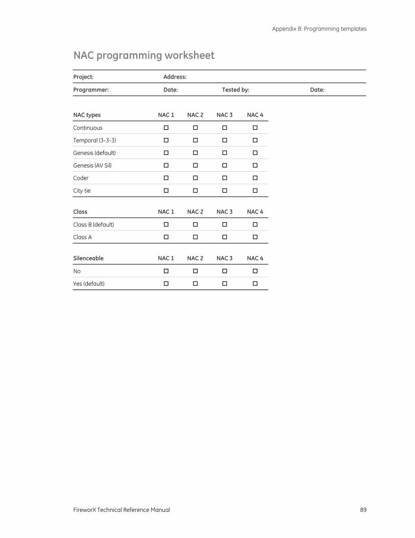
Appendix B: Programming templates
FireworX Technical Reference Manual 89
NAC programming worksheet
Project: Address:
Programmer: Date: Tested by: Date:
NAC types NAC 1 NAC 2 NAC 3 NAC 4
Continuous
Temporal (3-3-3)
Genesis (default)
Genesis (AV Sil)
Coder
City tie
Class NAC 1 NAC 2 NAC 3 NAC 4
Class B (default)
Class A
Silenceable NAC 1 NAC 2 NAC 3 NAC 4
No
Yes (default)
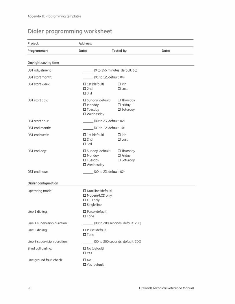
Appendix B: Programming templates
90 FireworX Technical Reference Manual
Dialer programming worksheet
Project: Address:
Programmer: Date: Tested by: Date:
Daylight saving time
DST adjustment: (0 to 255 minutes, default: 60)
DST start month: (01 to 12, default: 04)
DST start week: 1st (default) 4th 2nd Last 3rd
DST start day: Sunday (default) Thursday Monday Friday Tuesday Saturday Wednesday
DST start hour: (00 to 23, default: 02)
DST end month: (01 to 12, default: 10)
DST end week: 1st (default) 4th 2nd Last 3rd
DST end day: Sunday (default) Thursday Monday Friday Tuesday Saturday Wednesday
DST end hour: (00 to 23, default: 02)
Dialer configuration
Operating mode: Dual line (default) Modem/LCD only LCD only Single line
Line 1 dialing: Pulse (default) Tone
Line 1 supervision duration: (00 to 200 seconds, default: 200)
Line 2 dialing: Pulse (default) Tone
Line 2 supervision duration: (00 to 200 seconds, default: 200)
Blind call dialing: No (default) Yes
Line ground fault check: No Yes (default)
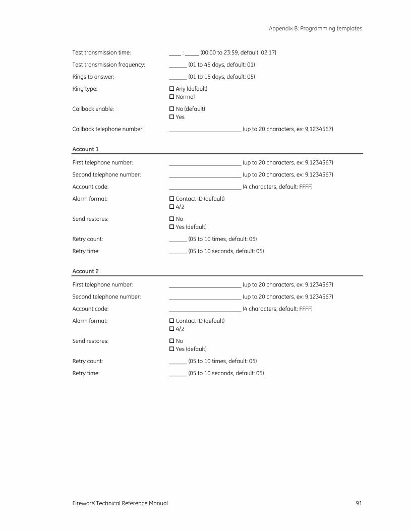
Appendix B: Programming templates
FireworX Technical Reference Manual 91
Test transmission time: : (00:00 to 23:59, default: 02:17)
Test transmission frequency: (01 to 45 days, default: 01)
Rings to answer: (01 to 15 days, default: 05)
Ring type: Any (default) Normal
Callback enable: No (default) Yes
Callback telephone number: (up to 20 characters, ex: 9,1234567)
Account 1
First telephone number: (up to 20 characters, ex: 9,1234567)
Second telephone number: (up to 20 characters, ex: 9,1234567)
Account code: (4 characters, default: FFFF)
Alarm format: Contact ID (default) 4/2
Send restores: No Yes (default)
Retry count: (05 to 10 times, default: 05)
Retry time: (05 to 10 seconds, default: 05)
Account 2
First telephone number: (up to 20 characters, ex: 9,1234567)
Second telephone number: (up to 20 characters, ex: 9,1234567)
Account code: (4 characters, default: FFFF)
Alarm format: Contact ID (default) 4/2
Send restores: No Yes (default)
Retry count: (05 to 10 times, default: 05)
Retry time: (05 to 10 seconds, default: 05)
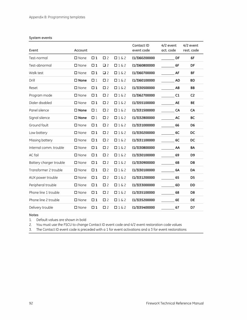
Appendix B: Programming templates
92 FireworX Technical Reference Manual
System events
Event
Account
Contact ID event code
4/2 event act. code
4/2 event rest. code
Test-normal None 1 2 1 & 2 (1/3)60200000 DF 6F
Test-abnormal None 1 2 1 & 2 (1/3)60800000 6F DF
Walk test None 1 2 1 & 2 (1/3)60700000 AF BF
Drill None 1 2 1 & 2 (1/3)60100000 AD BD
Reset None 1 2 1 & 2 (1/3)30500000 AB BB
Program mode None 1 2 1 & 2 (1/3)62700000 C1 C2
Dialer disabled None 1 2 1 & 2 (1/3)55100000 AE BE
Panel silence None 1 2 1 & 2 (1/3)31500000 CA CA
Signal silence None 1 2 1 & 2 (1/3)32800000 AC BC
Ground fault None 1 2 1 & 2 (1/3)31000000 66 D6
Low battery None 1 2 1 & 2 (1/3)30200000 6C DC
Missing battery None 1 2 1 & 2 (1/3)31100000 6C DC
Internal comm. trouble None 1 2 1 & 2 (1/3)30800000 AA BA
AC fail None 1 2 1 & 2 (1/3)30100000 69 D9
Battery charger trouble None 1 2 1 & 2 (1/3)30900000 6B DB
Transformer 2 trouble None 1 2 1 & 2 (1/3)30100000 6A DA
AUX power trouble None 1 2 1 & 2 (1/3)31200000 65 D5
Peripheral trouble None 1 2 1 & 2 (1/3)33000000 6D DD
Phone line 1 trouble None 1 2 1 & 2 (1/3)35100000 68 D8
Phone line 2 trouble None 1 2 1 & 2 (1/3)35200000 6E DE
Delivery trouble None 1 2 1 & 2 (1/3)35400000 67 D7
Notes 1. Default values are shown in bold 2. You must use the FSCU to change Contact ID event code and 4/2 event restoration code values 3. The Contact ID event code is preceded with a 1 for event activations and a 3 for event restorations
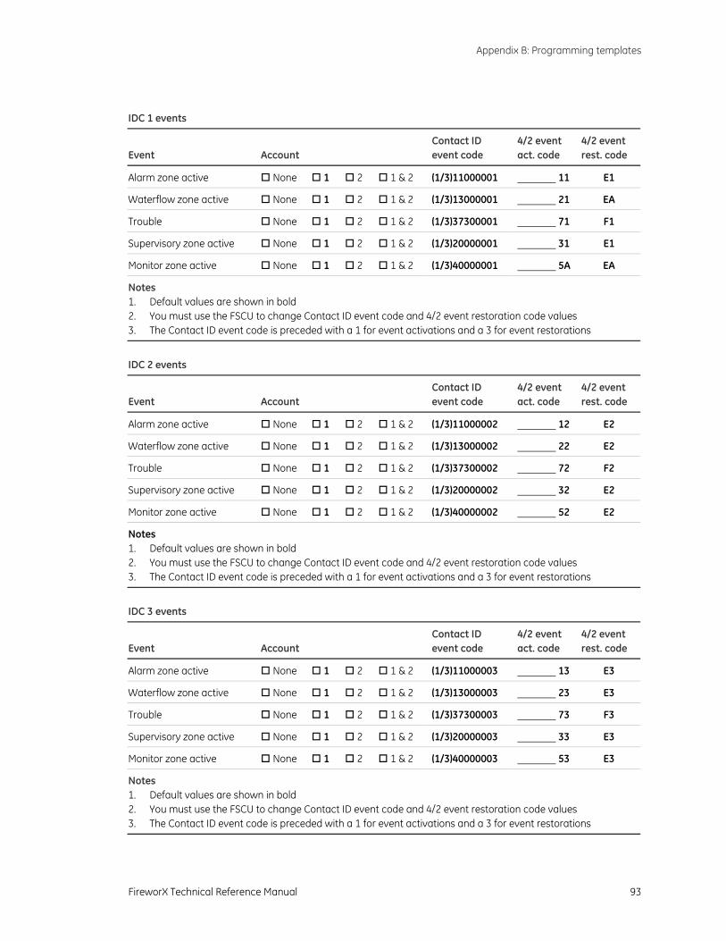
Appendix B: Programming templates
FireworX Technical Reference Manual 93
IDC 1 events
Event
Account
Contact ID event code
4/2 event act. code
4/2 event rest. code
Alarm zone active None 1 2 1 & 2 (1/3)11000001 11 E1
Waterflow zone active None 1 2 1 & 2 (1/3)13000001 21 EA
Trouble None 1 2 1 & 2 (1/3)37300001 71 F1
Supervisory zone active None 1 2 1 & 2 (1/3)20000001 31 E1
Monitor zone active None 1 2 1 & 2 (1/3)40000001 5A EA
Notes 1. Default values are shown in bold 2. You must use the FSCU to change Contact ID event code and 4/2 event restoration code values 3. The Contact ID event code is preceded with a 1 for event activations and a 3 for event restorations
IDC 2 events
Event
Account
Contact ID event code
4/2 event act. code
4/2 event rest. code
Alarm zone active None 1 2 1 & 2 (1/3)11000002 12 E2
Waterflow zone active None 1 2 1 & 2 (1/3)13000002 22 E2
Trouble None 1 2 1 & 2 (1/3)37300002 72 F2
Supervisory zone active None 1 2 1 & 2 (1/3)20000002 32 E2
Monitor zone active None 1 2 1 & 2 (1/3)40000002 52 E2
Notes 1. Default values are shown in bold 2. You must use the FSCU to change Contact ID event code and 4/2 event restoration code values 3. The Contact ID event code is preceded with a 1 for event activations and a 3 for event restorations
IDC 3 events
Event
Account
Contact ID event code
4/2 event act. code
4/2 event rest. code
Alarm zone active None 1 2 1 & 2 (1/3)11000003 13 E3
Waterflow zone active None 1 2 1 & 2 (1/3)13000003 23 E3
Trouble None 1 2 1 & 2 (1/3)37300003 73 F3
Supervisory zone active None 1 2 1 & 2 (1/3)20000003 33 E3
Monitor zone active None 1 2 1 & 2 (1/3)40000003 53 E3
Notes 1. Default values are shown in bold 2. You must use the FSCU to change Contact ID event code and 4/2 event restoration code values 3. The Contact ID event code is preceded with a 1 for event activations and a 3 for event restorations
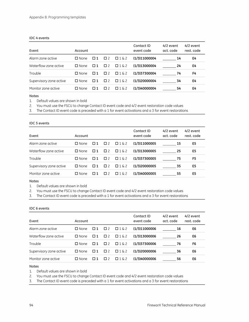
Appendix B: Programming templates
94 FireworX Technical Reference Manual
IDC 4 events
Event
Account
Contact ID event code
4/2 event act. code
4/2 event rest. code
Alarm zone active None 1 2 1 & 2 (1/3)11000004 14 E4
Waterflow zone active None 1 2 1 & 2 (1/3)13000004 24 E4
Trouble None 1 2 1 & 2 (1/3)37300004 74 F4
Supervisory zone active None 1 2 1 & 2 (1/3)20000004 34 E4
Monitor zone active None 1 2 1 & 2 (1/3)40000004 54 E4
Notes 1. Default values are shown in bold 2. You must use the FSCU to change Contact ID event code and 4/2 event restoration code values 3. The Contact ID event code is preceded with a 1 for event activations and a 3 for event restorations
IDC 5 events
Event
Account
Contact ID event code
4/2 event act. code
4/2 event rest. code
Alarm zone active None 1 2 1 & 2 (1/3)11000005 15 E5
Waterflow zone active None 1 2 1 & 2 (1/3)13000005 25 E5
Trouble None 1 2 1 & 2 (1/3)37300005 75 F5
Supervisory zone active None 1 2 1 & 2 (1/3)20000005 35 E5
Monitor zone active None 1 2 1 & 2 (1/3)40000005 55 E5
Notes 1. Default values are shown in bold 2. You must use the FSCU to change Contact ID event code and 4/2 event restoration code values 3. The Contact ID event code is preceded with a 1 for event activations and a 3 for event restorations
IDC 6 events
Event
Account
Contact ID event code
4/2 event act. code
4/2 event rest. code
Alarm zone active None 1 2 1 & 2 (1/3)11000006 16 E6
Waterflow zone active None 1 2 1 & 2 (1/3)13000006 26 E6
Trouble None 1 2 1 & 2 (1/3)37300006 76 F6
Supervisory zone active None 1 2 1 & 2 (1/3)20000006 36 E6
Monitor zone active None 1 2 1 & 2 (1/3)40000006 56 E6
Notes 1. Default values are shown in bold 2. You must use the FSCU to change Contact ID event code and 4/2 event restoration code values 3. The Contact ID event code is preceded with a 1 for event activations and a 3 for event restorations
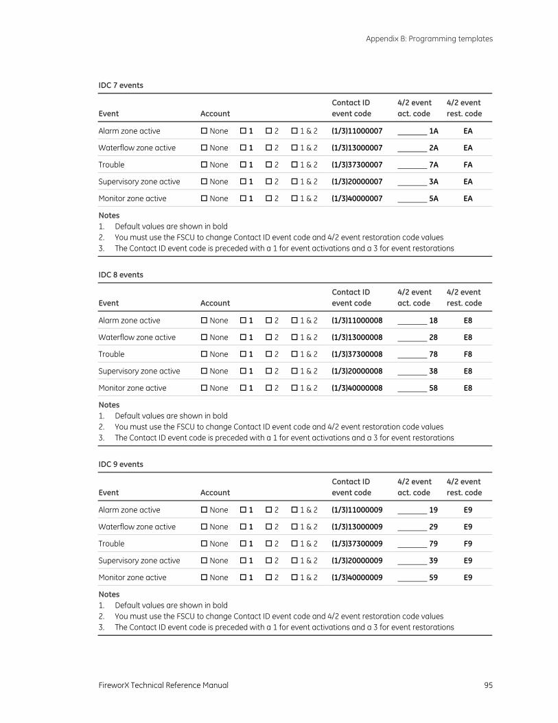
Appendix B: Programming templates
FireworX Technical Reference Manual 95
IDC 7 events
Event
Account
Contact ID event code
4/2 event act. code
4/2 event rest. code
Alarm zone active None 1 2 1 & 2 (1/3)11000007 1A EA
Waterflow zone active None 1 2 1 & 2 (1/3)13000007 2A EA
Trouble None 1 2 1 & 2 (1/3)37300007 7A FA
Supervisory zone active None 1 2 1 & 2 (1/3)20000007 3A EA
Monitor zone active None 1 2 1 & 2 (1/3)40000007 5A EA
Notes 1. Default values are shown in bold 2. You must use the FSCU to change Contact ID event code and 4/2 event restoration code values 3. The Contact ID event code is preceded with a 1 for event activations and a 3 for event restorations
IDC 8 events
Event
Account
Contact ID event code
4/2 event act. code
4/2 event rest. code
Alarm zone active None 1 2 1 & 2 (1/3)11000008 18 E8
Waterflow zone active None 1 2 1 & 2 (1/3)13000008 28 E8
Trouble None 1 2 1 & 2 (1/3)37300008 78 F8
Supervisory zone active None 1 2 1 & 2 (1/3)20000008 38 E8
Monitor zone active None 1 2 1 & 2 (1/3)40000008 58 E8
Notes 1. Default values are shown in bold 2. You must use the FSCU to change Contact ID event code and 4/2 event restoration code values 3. The Contact ID event code is preceded with a 1 for event activations and a 3 for event restorations
IDC 9 events
Event
Account
Contact ID event code
4/2 event act. code
4/2 event rest. code
Alarm zone active None 1 2 1 & 2 (1/3)11000009 19 E9
Waterflow zone active None 1 2 1 & 2 (1/3)13000009 29 E9
Trouble None 1 2 1 & 2 (1/3)37300009 79 F9
Supervisory zone active None 1 2 1 & 2 (1/3)20000009 39 E9
Monitor zone active None 1 2 1 & 2 (1/3)40000009 59 E9
Notes 1. Default values are shown in bold 2. You must use the FSCU to change Contact ID event code and 4/2 event restoration code values 3. The Contact ID event code is preceded with a 1 for event activations and a 3 for event restorations
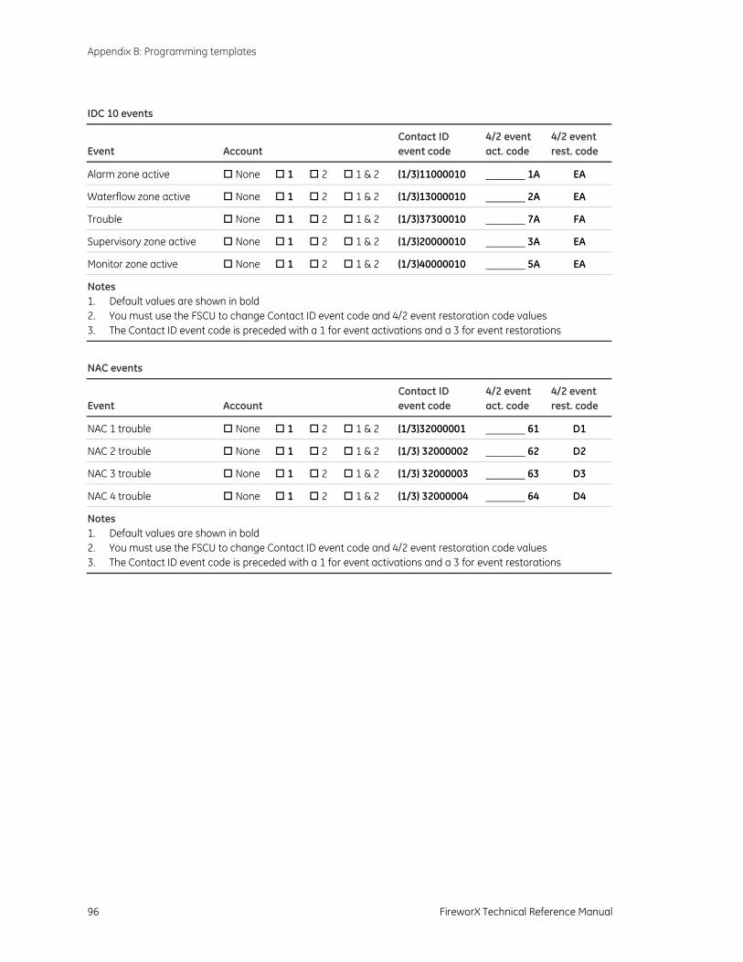
Appendix B: Programming templates
96 FireworX Technical Reference Manual
IDC 10 events
Event
Account
Contact ID event code
4/2 event act. code
4/2 event rest. code
Alarm zone active None 1 2 1 & 2 (1/3)11000010 1A EA
Waterflow zone active None 1 2 1 & 2 (1/3)13000010 2A EA
Trouble None 1 2 1 & 2 (1/3)37300010 7A FA
Supervisory zone active None 1 2 1 & 2 (1/3)20000010 3A EA
Monitor zone active None 1 2 1 & 2 (1/3)40000010 5A EA
Notes 1. Default values are shown in bold 2. You must use the FSCU to change Contact ID event code and 4/2 event restoration code values 3. The Contact ID event code is preceded with a 1 for event activations and a 3 for event restorations
NAC events
Event
Account
Contact ID event code
4/2 event act. code
4/2 event rest. code
NAC 1 trouble None 1 2 1 & 2 (1/3)32000001 61 D1
NAC 2 trouble None 1 2 1 & 2 (1/3) 32000002 62 D2
NAC 3 trouble None 1 2 1 & 2 (1/3) 32000003 63 D3
NAC 4 trouble None 1 2 1 & 2 (1/3) 32000004 64 D4
Notes 1. Default values are shown in bold 2. You must use the FSCU to change Contact ID event code and 4/2 event restoration code values 3. The Contact ID event code is preceded with a 1 for event activations and a 3 for event restorations

FireworX Technical Reference Manual 97
Appendix C Wiring diagrams
Summary
This appendix provides typical system wiring diagrams.
Content
Warnings, cautions, and notes • 98 Figure 10: Field wire connections, three-zone control panel • 100 Figure 11: Field wire connections, five-zone control panel • 101 Figure 12: Field wire connections, ten-zone control panels • 102 Figure 13: Wire routing diagram • 103 Figure 14: Mains AC and battery wiring, three- and five-zone control panels • 104 Figure 15: Mains AC and battery wiring, ten-zone control panels • 105 Figure 16: Typical alarm circuit • 106 Figure 17: Typical 4-wire smoke detector circuit • 106 Figure 18: Typical waterflow alarm circuit • 106 Figure 19: Typical supervisory circuit • 106 Figure 20: Typical waterflow/supervisory combination circuit • 107 Figure 21: Typical remote signal silence/drill circuit • 107 Figure 22: Typical notification appliance circuit • 107 Figure 23: Typical F-DACT(F) wiring • 108 Figure 24: Typical remote indicator wiring for three- and five-zone systems • 109 Figure 25: Typical remote indicator wiring for ten-zone systems • 110 Figure 26: Typical FSRRM24 wiring • 111 Figure 27: FSUIM wiring for a graphic annunciator panel, three- and five-zone systems • 112 Figure 29: Typical CTM wiring • 113 Figure 29: Typical cross zone wiring • 114
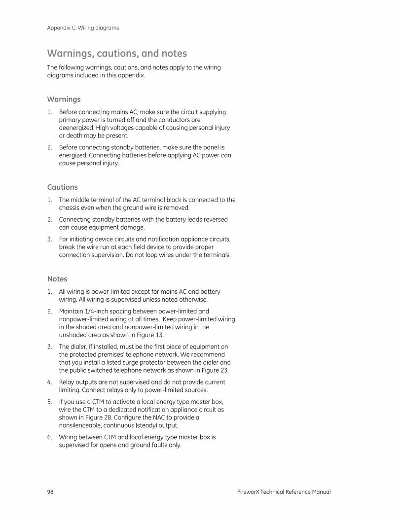
Appendix C: Wiring diagrams
98 FireworX Technical Reference Manual
Warnings, cautions, and notes The following warnings, cautions, and notes apply to the wiring diagrams included in this appendix.
Warnings
1. Before connecting mains AC, make sure the circuit supplying primary power is turned off and the conductors are deenergized. High voltages capable of causing personal injury or death may be present.
2. Before connecting standby batteries, make sure the panel is energized. Connecting batteries before applying AC power can cause personal injury.
Cautions 1. The middle terminal of the AC terminal block is connected to the
chassis even when the ground wire is removed.
2. Connecting standby batteries with the battery leads reversed can cause equipment damage.
3. For initiating device circuits and notification appliance circuits, break the wire run at each field device to provide proper connection supervision. Do not loop wires under the terminals.
Notes
1. All wiring is power-limited except for mains AC and battery wiring. All wiring is supervised unless noted otherwise.
2. Maintain 1/4-inch spacing between power-limited and nonpower-limited wiring at all times. Keep power-limited wiring in the shaded area and nonpower-limited wiring in the unshaded area as shown in Figure 13.
3. The dialer, if installed, must be the first piece of equipment on the protected premises’ telephone network. We recommend that you install a listed surge protector between the dialer and the public switched telephone network as shown in Figure 23.
4. Relay outputs are not supervised and do not provide current limiting. Connect relays only to power-limited sources.
5. If you use a CTM to activate a local energy type master box, wire the CTM to a dedicated notification appliance circuit as shown in Figure 28. Configure the NAC to provide a nonsilenceable, continuous (steady) output.
6. Wiring between CTM and local energy type master box is supervised for opens and ground faults only.
Appendix C: Wiring diagrams
FireworX Technical Reference Manual 99
7. NFPA 72 allows systems that require the operation of two automatic detectors (cross zones) to initiate an alarm response, provided:
• The systems are not prohibited by the authority having jurisdiction.
• At least two automatic detectors are in each protected space.
• The alarm verification feature is not used.
• You reduce the detector installation spacing to 0.7 times the linear spacing.
8. Panel must be connected to a 15 A branch circuit, max.
9. Installing detectors from different manufacturers on the same initiating device circuit is not allowed.
10. All FSUIM relays are common. FSRRM24 relays can be configured as common, zone, or programmable,
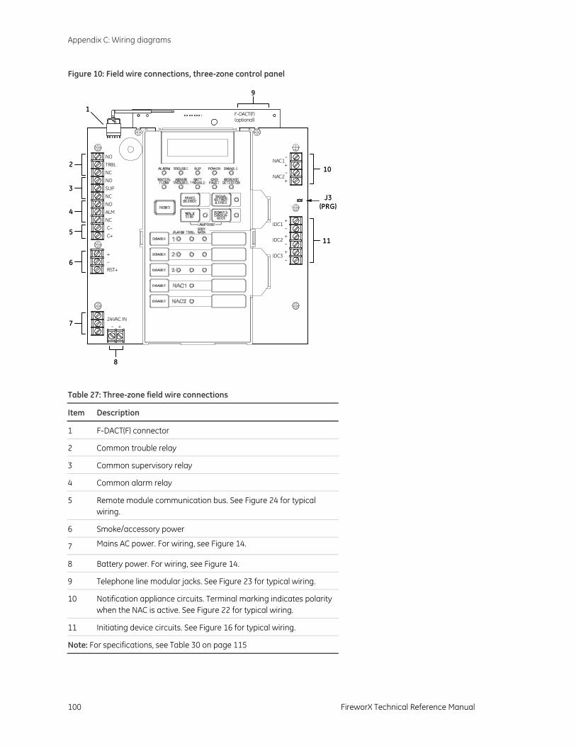
Appendix C: Wiring diagrams
100 FireworX Technical Reference Manual
Figure 10: Field wire connections, three-zone control panel
–NAC1
+
C–C+
–+
TRBL
+–
F-DACT(F)(optional)
RST+
24VAC IN
–NAC2
+
IDC1+–
IDC2+–
IDC3+
–
NO
NC
SUPNO
NC
ALMNO
NC
2
3
4
5
6
7
8
9
10
11
1
J3(PRG)
Table 27: Three-zone field wire connections
Item Description
1 F-DACT(F) connector
2 Common trouble relay
3 Common supervisory relay
4 Common alarm relay
5 Remote module communication bus. See Figure 24 for typical wiring.
6 Smoke/accessory power
7 Mains AC power. For wiring, see Figure 14.
8 Battery power. For wiring, see Figure 14.
9 Telephone line modular jacks. See Figure 23 for typical wiring.
10 Notification appliance circuits. Terminal marking indicates polarity when the NAC is active. See Figure 22 for typical wiring.
11 Initiating device circuits. See Figure 16 for typical wiring.
Note: For specifications, see Table 30 on page 115
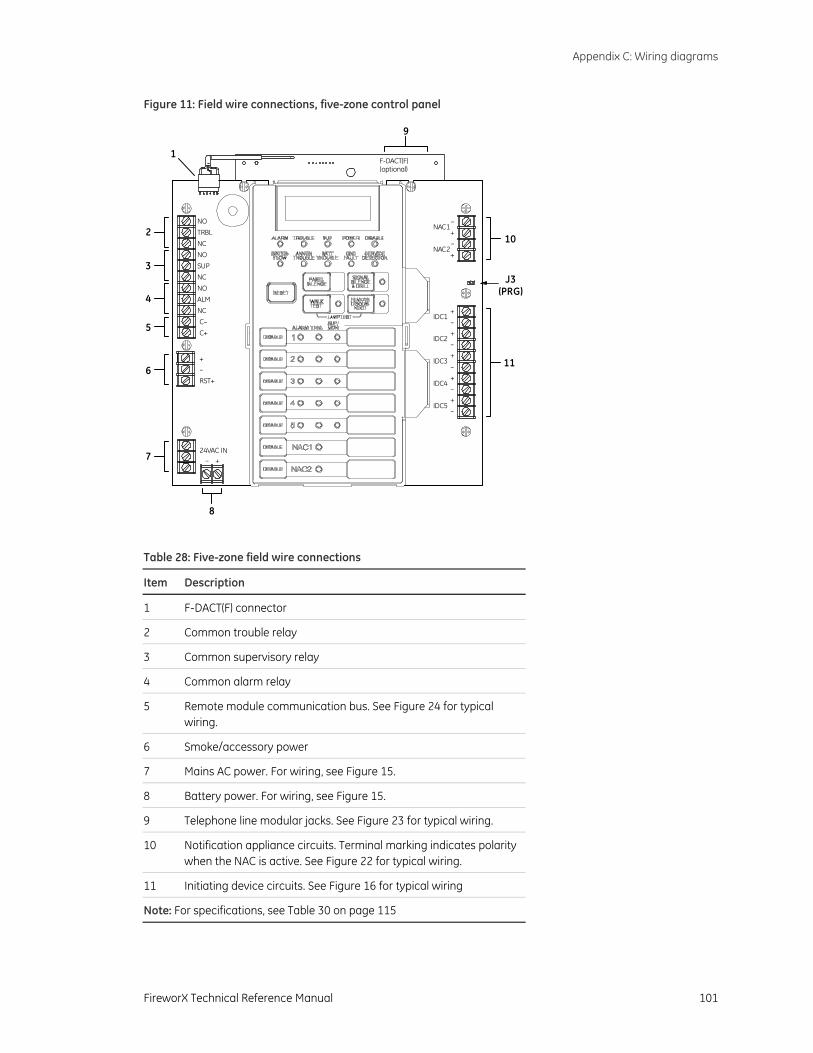
Appendix C: Wiring diagrams
FireworX Technical Reference Manual 101
Figure 11: Field wire connections, five-zone control panel
–NAC1
+
C–C+
–+
TRBL
+–
F-DACT(F)(optional)
RST+
24VAC IN
–NAC2
+
IDC1+–
IDC2+–
IDC3+
–
IDC4+–
IDC5+–
NO
NC
SUPNO
NC
ALMNO
NC
2
3
4
5
6
7
8
9
10
11
1
J3(PRG)
Table 28: Five-zone field wire connections
Item Description
1 F-DACT(F) connector
2 Common trouble relay
3 Common supervisory relay
4 Common alarm relay
5 Remote module communication bus. See Figure 24 for typical wiring.
6 Smoke/accessory power
7 Mains AC power. For wiring, see Figure 15.
8 Battery power. For wiring, see Figure 15.
9 Telephone line modular jacks. See Figure 23 for typical wiring.
10 Notification appliance circuits. Terminal marking indicates polarity when the NAC is active. See Figure 22 for typical wiring.
11 Initiating device circuits. See Figure 16 for typical wiring
Note: For specifications, see Table 30 on page 115

Appendix C: Wiring diagrams
102 FireworX Technical Reference Manual
Figure 12: Field wire connections, ten-zone control panels
C–C+
–+
RST+
ALM
SUP
TRBL
+−
F-DACT(F)(optional)
24VAC IN
EGND
–NAC1
+–
NAC2+–
NAC3+
–NAC4
+
IDC1+
–
IDC2+
–
IDC3+
–
IDC4+
–
IDC5+
–
IDC6+–
IDC7+–
IDC8+–
IDC9+
–
IDC10+–
NO
NO
NO
NC
NC
NC
2
3
4
5
6
7
8
9
10
11
12
1
J3 (PRG)
Table 29: Ten-zone field wire connections
Item Description Item Description
1 F-DACT(F) connector 7 Mains AC power. For wiring, see Figure 15.
2 Common trouble relay 8 Expander transformer. For wiring, see Figure 15.
3 Common supervisory relay 9 Battery power. For wiring, see Figure 15.
4 Common alarm relay 10 Telephone line modular jacks. See Figure 23 for typical wiring.
5 Remote module communication bus. See Figure 24 for typical wiring.
11 Notification appliance circuits. Terminal markingindicates polarity when the NAC is active. See Figure 22 for typical wiring.
6 Smoke/accessory power 12 Initiating device circuits. See Figure 16 for typical wiring.
Note: For specifications, see Table 30 on page 115
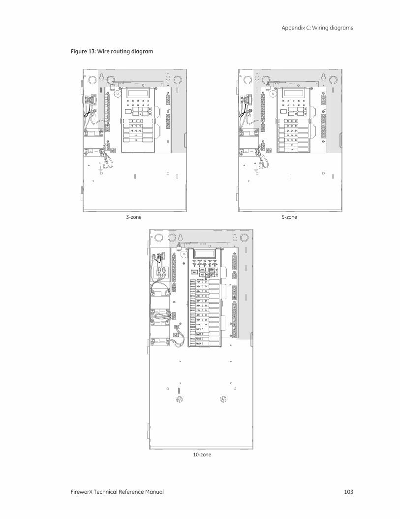
Appendix C: Wiring diagrams
FireworX Technical Reference Manual 103
Figure 13: Wire routing diagram
3-zone 5-zone
10-zone
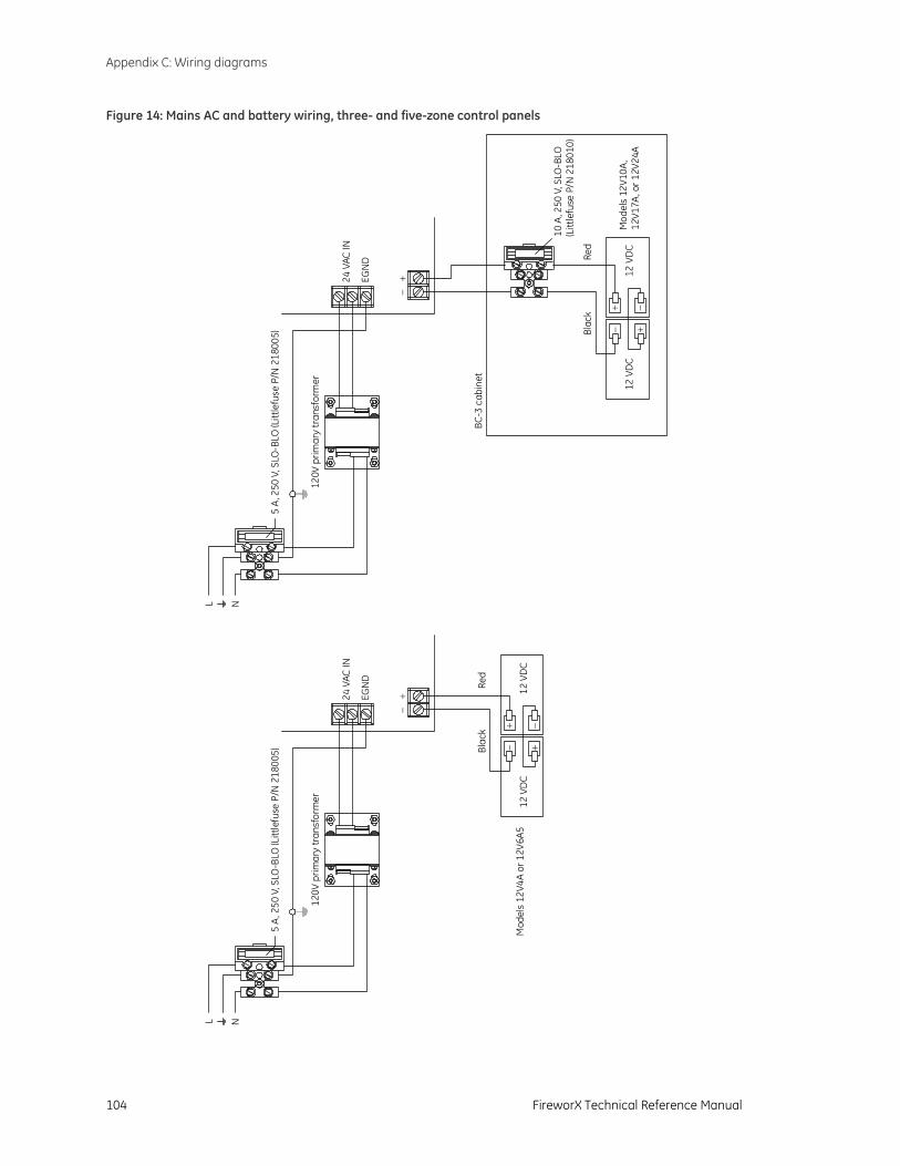
Appendix C: Wiring diagrams
104 FireworX Technical Reference Manual
Figure 14: Mains AC and battery wiring, three- and five-zone control panels
Red
Blac
k
L N
+−
− +12
VD
C+ −
12 V
DC
120V
prim
ary
tran
sfor
mer
5 A,
250
V, S
LO-B
LO (L
ittle
fuse
P/N
218
005)
24 V
AC IN
EGN
D
Red
Blac
k
L N
+−
− +12
VD
C+ −
12 V
DC
120V
prim
ary
tran
sfor
mer
5 A,
250
V, S
LO-B
LO (L
ittle
fuse
P/N
218
005)
24 V
AC IN
EGN
D
10 A
, 250
V, S
LO-B
LO(L
ittle
fuse
P/N
218
010)
BC-3
cab
inet
Mod
els
12V4
A or
12V
6A5
Mod
els
12V1
0A,
12V1
7A, o
r 12V
24A
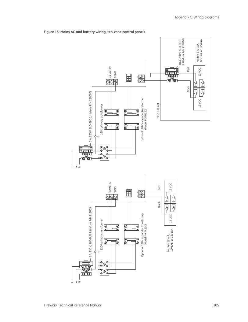
Appendix C: Wiring diagrams
FireworX Technical Reference Manual 105
Figure 15: Mains AC and battery wiring, ten-zone control panels
Red
Blac
k
L N
+−
− +12
VD
C+ −
12 V
DC
120V
prim
ary
tran
sfor
mer
Opt
iona
l 120
V ex
pand
er tr
ansf
orm
er(M
odel
F-X
TR12
0)
5 A,
250
V, S
LO-B
LO (L
ittle
fuse
P/N
218
005)
24 V
AC IN
EGN
D
Red
Blac
k
L N
+−
− +12
VD
C+ −
12 V
DC
120V
prim
ary
tran
sfor
mer
optio
nal 1
20V
expa
nder
tran
sfor
mer
(Mod
el F
-XTR
120)
5 A,
250
V, S
LO-B
LO (L
ittle
fuse
P/N
218
005)
24 V
AC IN
EGN
D
BC-3
cab
inet
Mod
els
12V1
0A,
12V1
7A, o
r 12V
24A
Mod
els
12V4
A,12
V6A5
, or 1
2V10
A
10 A
, 250
V, S
LO-B
LO(L
ittle
fuse
P/N
218
010)
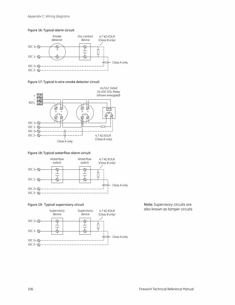
Appendix C: Wiring diagrams
106 FireworX Technical Reference Manual
Figure 16: Typical alarm circuit
4.7 k EOLR(Class B only)
Ω
+–
IDC 1+
IDC 2+IDC 2–
IDC 1–
Smokedetector
Dry contactdevice
Class A only
Figure 17: Typical 4-wire smoke detector circuit
IDC 1+IDC 1–IDC 2+IDC 2–
+–
RST+
4.7 k EOLR(Class B only)
Ω
UL/ULC listed24 VDC EOL Relay(shown energized)
−+ −+
Class A only
Figure 18: Typical waterflow alarm circuit
4.7 k EOLR(Class B only)
Ω
IDC 1+
IDC 2+IDC 2–
IDC 1–
Waterflowswitch
Class A only
Waterflowswitch
Figure 19: Typical supervisory circuit
4.7 k EOLR(Class B only)
Ω
IDC 1+
IDC 2+IDC 2–
IDC 1–
Supervisorydevice
Supervisorydevice
Class A only
Note: Supervisory circuits are also known as tamper circuits

Appendix C: Wiring diagrams
FireworX Technical Reference Manual 107
Figure 20: Typical waterflow/supervisory combination circuit
3.6 kEOLR
ΩIDC 1+
IDC 1–
Waterflowswitch
Supervisorydevice1.1 k
EOLRΩ
Figure 21: Typical remote signal silence/drill circuit
3.6 kEOLR
ΩIDC 1+
IDC 1–
Drillswitch
Signal Silenceswitch 1.1 k
EOLRΩ
Figure 22: Typical notification appliance circuit
4.7 k EOLR(Class B only)
Ω
NAC 1–
GenesisTemporal
Horn/Strobe
NAC 1+
NAC 2–NAC 2+
GenesisTemporal
Horn/Strobe
– –
+ +NormalActive+–
–+
+–
–+
Class A only
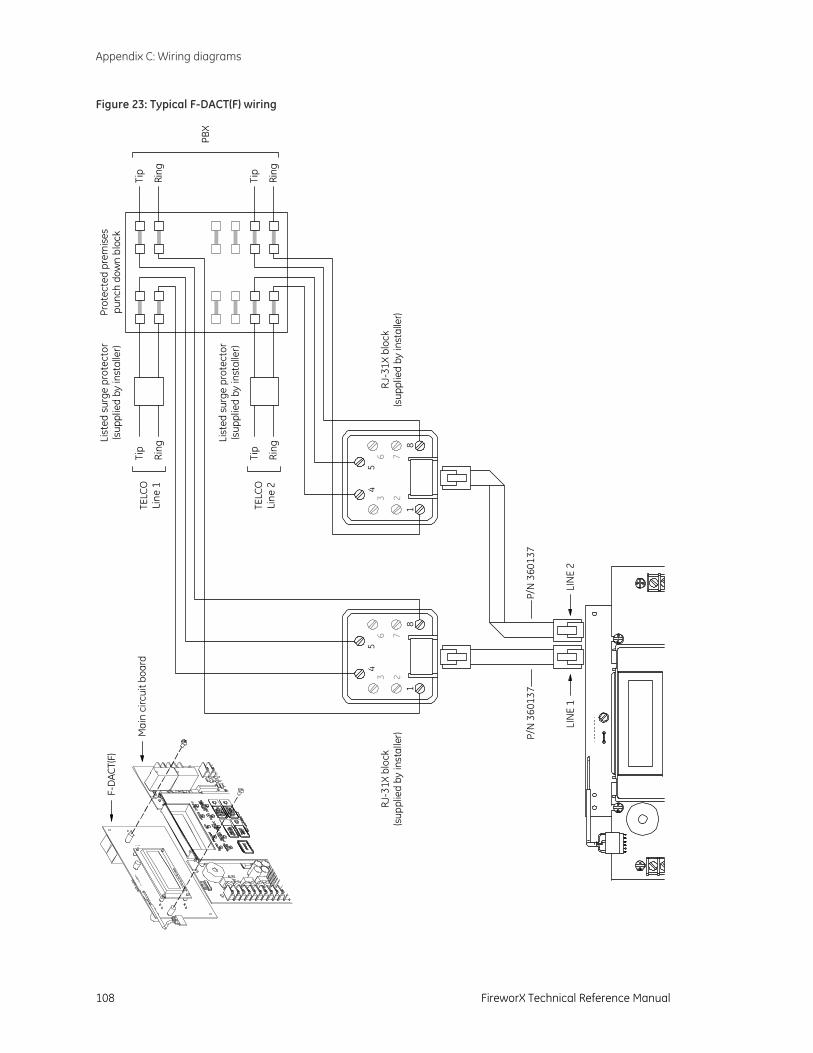
Appendix C: Wiring diagrams
108 FireworX Technical Reference Manual
Figure 23: Typical F-DACT(F) wiring F-
DAC
T(F)
Mai
n ci
rcui
t boa
rdTi
p
Ring
Tip
Ring
Tip
Ring
Tip
Ring
Prot
ecte
d pr
emis
espu
nch
dow
n bl
ock
TELC
OLi
ne 1
TELC
OLi
ne 2
PBX
P/N
360
137
LIN
E 1
234
5
76
81
LIN
E 2
234
5
76
81
RJ-3
1X b
lock
(sup
plie
d by
inst
alle
r)RJ
-31X
blo
ck(s
uppl
ied
by in
stal
ler)
P/N
360
137
List
ed s
urge
pro
tect
or(s
uppl
ied
by in
stal
ler)
List
ed s
urge
pro
tect
or(s
uppl
ied
by in
stal
ler)
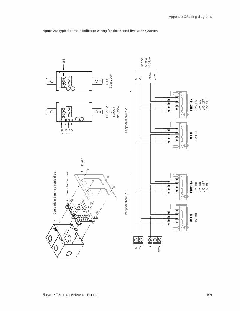
Appendix C: Wiring diagrams
FireworX Technical Reference Manual 109
Figure 24: Typical remote indicator wiring for three- and five-zone systems
JP2
FSRS
I(re
ar v
iew
)FS
RZI-
SAor
FSRZ
I-A(re
ar v
iew
)
JP5
JP4
JP3
JP2
Com
patib
le 2
-gan
g el
ectr
ical
box
Rem
ote
mod
ules
FSAT
2
–+
RST+
FSRS
IFS
RZI-
SAFS
RSI
FSRZ
I-SA
C+C–
JP2:
ON
JP2:
OFF
24 V
–24
V+
C+C–
To n
ext
rem
ote
mod
ule
Perip
hera
l gro
up 1
Perip
hera
l gro
up 2
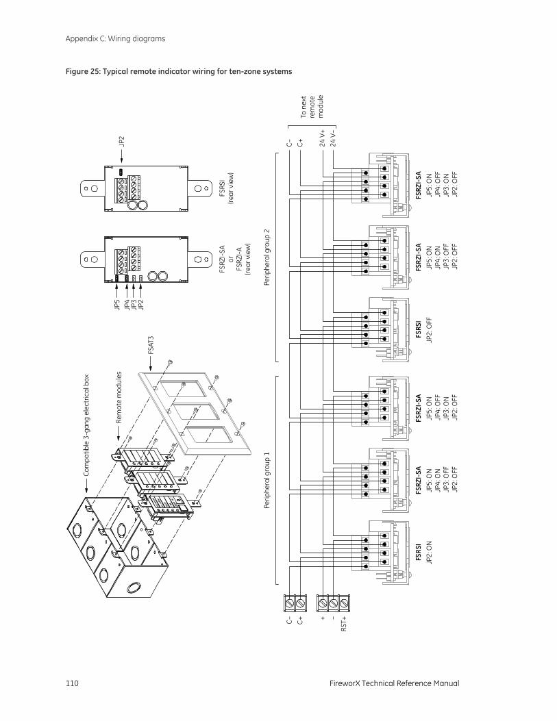
Appendix C: Wiring diagrams
110 FireworX Technical Reference Manual
Figure 25: Typical remote indicator wiring for ten-zone systems
–+
RST+
FSRS
IFS
RZI-
SAFS
RZI-
SAFS
RSI
FSRZ
I-SA
FSRZ
I-SA
C+C–
JP2:
ON
JP5:
ON
JP4:
OFF
JP3:
ON
JP2:
OFF
JP2:
OFF
24 V
–24
V+
C+C–
To n
ext
rem
ote
mod
ule
Perip
hera
l gro
up 1
Perip
hera
l gro
up 2
Com
patib
le 3
-gan
g el
ectr
ical
box
Rem
ote
mod
ules
FSAT
3
JP2
FSRS
I(re
ar v
iew
)
JP5
JP4
JP3
JP2
FSRZ
I-SA
orFS
RZI-A
(rear
vie
w)
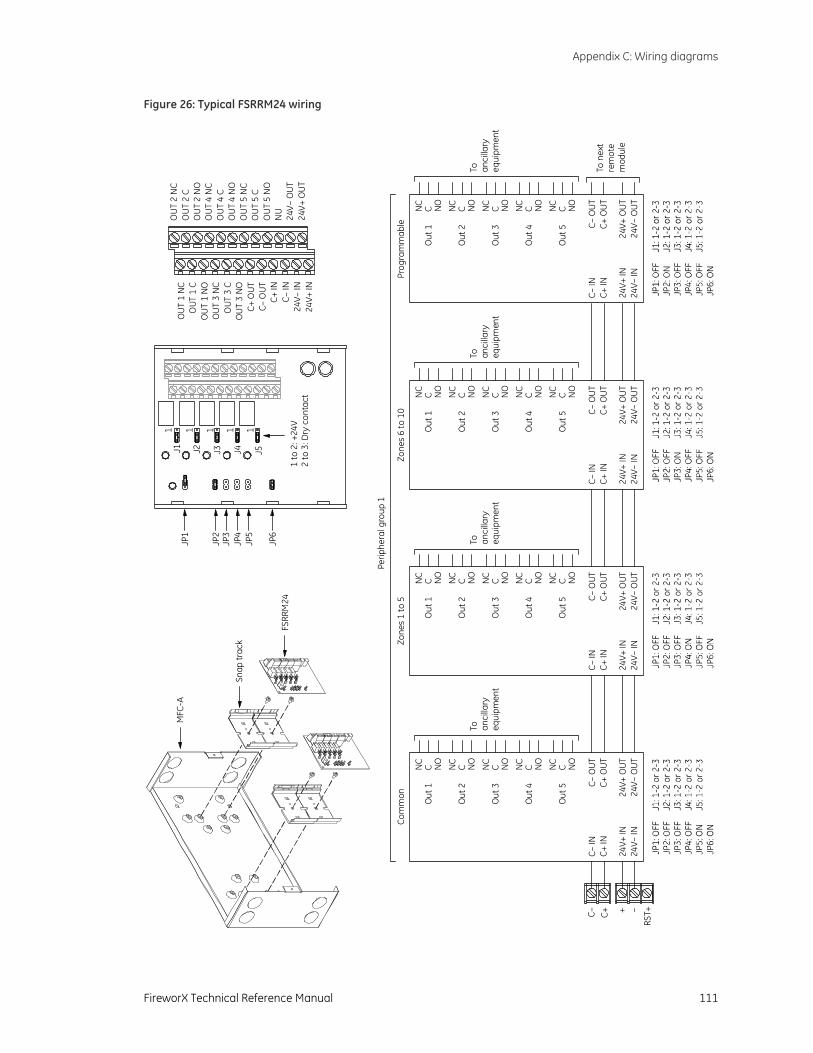
Appendix C: Wiring diagrams
FireworX Technical Reference Manual 111
Figure 26: Typical FSRRM24 wiring
MFC
-A
Snap
trac
k
FSRR
M24
–+
RST+C+C–
Out
1
Out
2
Out
3
Out
4
Out
5
NC
C NO
NC
C NO
NC
C NO
NC
C NO
NC
C NO
C– O
UT
C+ O
UT
24V+
OU
T24
V– O
UT
C– IN
C+ IN
24V+
IN24
V– IN
To anci
llary
equi
pmen
t
To n
ext
rem
ote
mod
ule
Com
mon
Zone
s 1
to 5
Zone
s 6
to 1
0Pr
ogra
mm
able
Perip
hera
l gro
up 1
Out
1O
ut 1
Out
1
Out
2O
ut 2
Out
2
Out
3O
ut 3
Out
3
Out
4O
ut 4
Out
4
Out
5O
ut 5
Out
5
NC
NC
NC
CC
CN
ON
ON
ON
CN
CN
CC
CC
NO
NO
NO
NC
NC
NC
CC
CN
ON
ON
ON
CN
CN
CC
CC
NO
NO
NO
NC
NC
NC
CC
CN
ON
ON
O
C– O
UTC–
OU
TC–
OU
TC+
OUT
C+ O
UT
C+ O
UT
24V+
OUT
24V+
OU
T24
V+ O
UT
24V–
OUT
24V–
OU
T24
V– O
UT
C– IN
C– IN
C– IN
C+ IN
C+ IN
C+ IN
24V+
IN24
V+ IN
24V+
IN24
V– IN
24V–
IN24
V– IN
To anci
llary
equi
pmen
t
To anci
llary
equi
pmen
t
To anci
llary
equi
pmen
t
JP1
JP2
JP3
JP4
JP5
JP6
J1 J2 J3 J4 J5
24V+
OU
T24
V– O
UT
NU
OU
T 5
NO
OU
T 5
C
OU
T 2
NC
OU
T 2
CO
UT
2 N
OO
UT
4 N
CO
UT
4 C
OU
T 4
NO
OU
T 5
NC
24V+
IN24
V– IN
C+ IN
C– O
UT
OU
T 1
NC
OUT
1 C
OU
T 1
NO
OU
T 3
NC
OUT
3 C
OU
T 3
NO
C+ O
UT
C– IN
1 to
2: +
24V
2 to
3: D
ry c
onta
ct
1 1 1 1 1
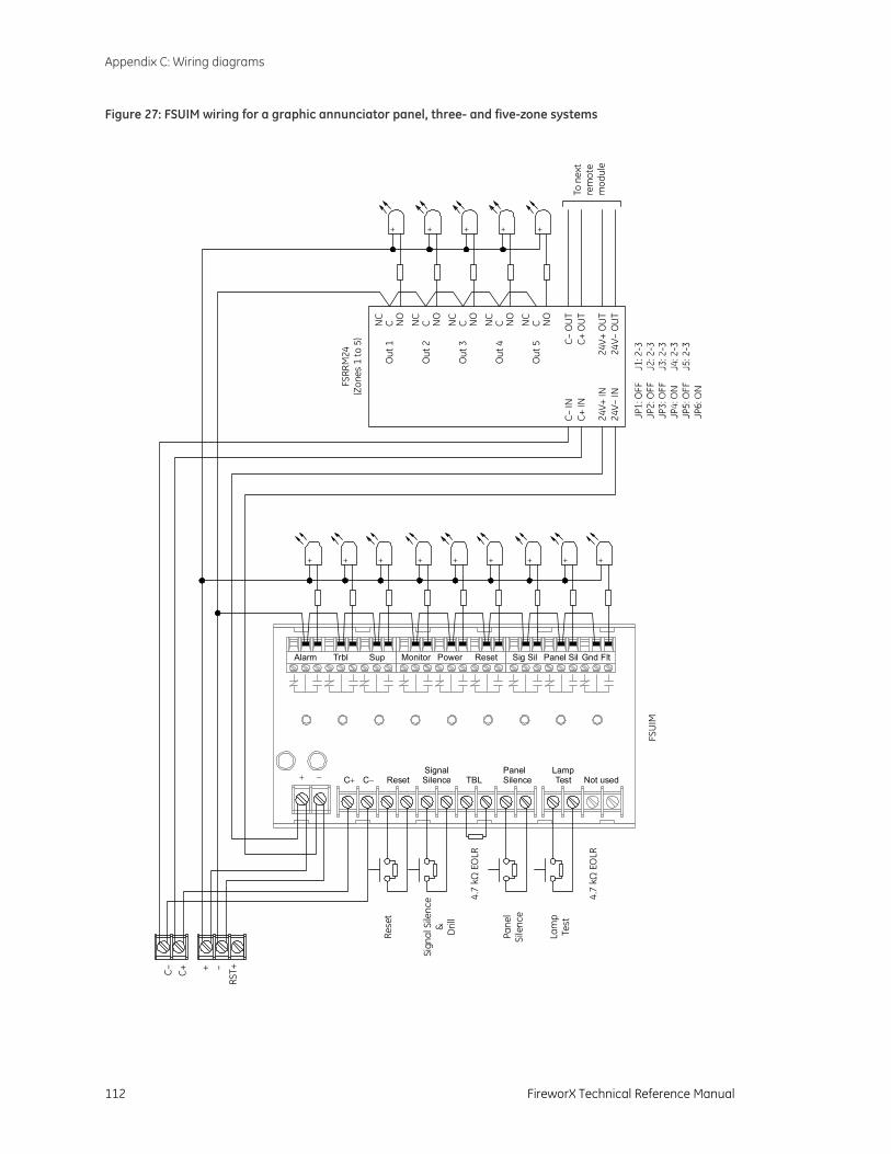
Appendix C: Wiring diagrams
112 FireworX Technical Reference Manual
Figure 27: FSUIM wiring for a graphic annunciator panel, three- and five-zone systems
+ − C+ C− ResetSignalSilence
PanelSilence
LampTestTBL
Alarm Trbl Sup Monitor Power Reset Sig Sil Panel Sil Gnd Flt
Not used
–+
RST+C+C–
To n
ext
rem
ote
mod
ule
FSRR
M24
(Zon
es 1
to 5
)
Out
1
Out
2
Out
3
Out
4
Out
5
NC
C NO
NC
C NO
NC
C NO
NC
C NO
NC
C NO
C– O
UT
C+ O
UT
24V+
OU
T24
V– O
UT
C– IN
C+ IN
24V+
IN24
V– IN
+
Rese
t
Sign
al S
ilenc
e& Dril
l
Pane
lSi
lenc
e
Lam
pTe
st+ + + + + + + +
FSU
IM
+ + + + +
4.7
kΩ E
OLR
4.7
kΩ E
OLR
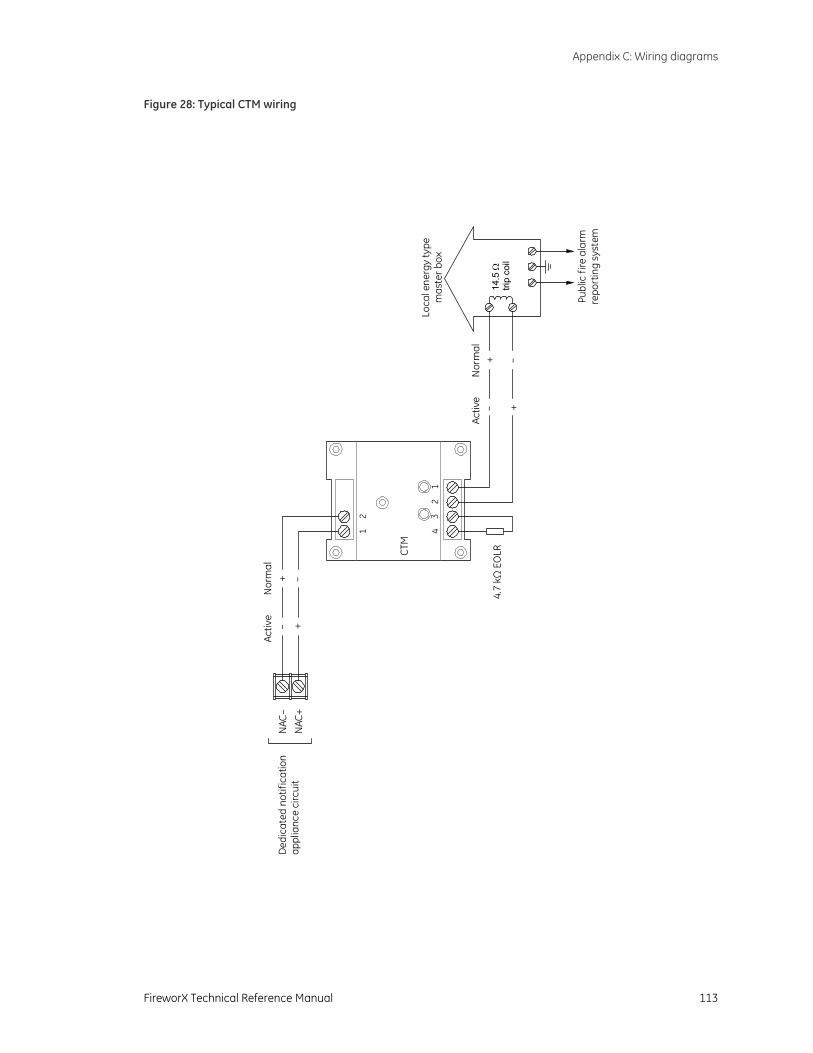
Appendix C: Wiring diagrams
FireworX Technical Reference Manual 113
Figure 28: Typical CTM wiring
CTM
21
12
34
+ –Ac
tive
Nor
mal
Publ
ic fi
re a
larm
repo
rtin
g sy
stem
Loca
l ene
rgy
type
mas
ter b
ox
14.5
tri
p co
ilΩ
+ –
+ –+ –
NAC
–N
AC+
4.7
k E
OLR
Ω
Activ
eN
orm
al
Ded
icat
ed n
otifi
catio
nap
plia
nce
circ
uit
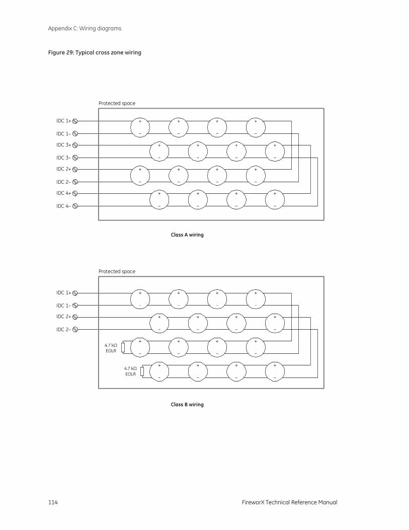
Appendix C: Wiring diagrams
114 FireworX Technical Reference Manual
Figure 29: Typical cross zone wiring
IDC 1+
IDC 1–
+
+
+
+
+
+
+
+
+
+
+
+
+
+
+
+
IDC 2+
IDC 2–
4.7 kΩEOLR
4.7 kΩEOLR
Protected space
IDC 1+
IDC 1–
+
+
+
+
+
+
+
+
+
+
+
+
+
+
+
+
IDC 3+
IDC 3–
IDC 2–
IDC 4–
IDC 2+
IDC 4+
Protected space
Class B wiring
Class A wiring
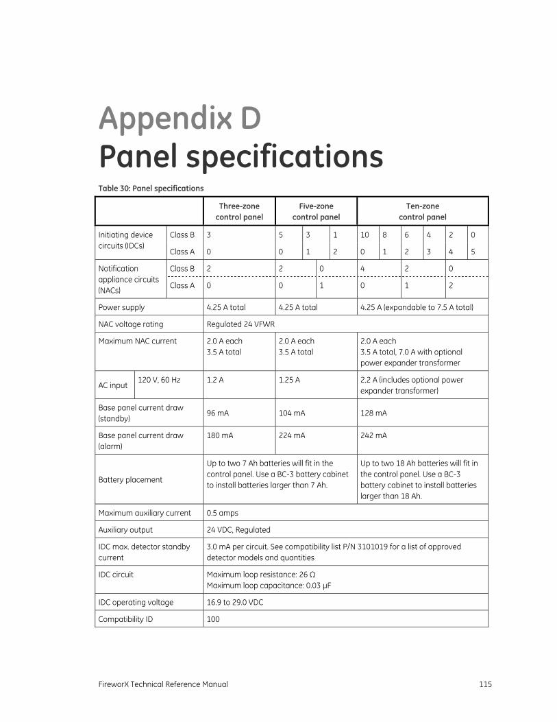
FireworX Technical Reference Manual 115
Appendix D Panel specifications Table 30: Panel specifications
Three-zone control panel
Five-zone control panel
Ten-zone control panel
Class B 3 5 3 1 10 8 6 4 2 0 Initiating device circuits (IDCs)
Class A 0 0 1 2 0 1 2 3 4 5
Class B 2 2 0 4 2 0 Notification appliance circuits (NACs) Class A 0 0 1 0 1 2
Power supply 4.25 A total 4.25 A total 4.25 A (expandable to 7.5 A total)
NAC voltage rating Regulated 24 VFWR
Maximum NAC current 2.0 A each 3.5 A total
2.0 A each 3.5 A total
2.0 A each 3.5 A total, 7.0 A with optional power expander transformer
AC input 120 V, 60 Hz 1.2 A 1.25 A 2.2 A (includes optional power
expander transformer)
Base panel current draw (standby)
96 mA 104 mA 128 mA
Base panel current draw (alarm)
180 mA 224 mA 242 mA
Battery placement
Up to two 7 Ah batteries will fit in the control panel. Use a BC-3 battery cabinet to install batteries larger than 7 Ah.
Up to two 18 Ah batteries will fit in the control panel. Use a BC-3 battery cabinet to install batteries larger than 18 Ah.
Maximum auxiliary current 0.5 amps
Auxiliary output 24 VDC, Regulated
IDC max. detector standby current
3.0 mA per circuit. See compatibility list P/N 3101019 for a list of approved detector models and quantities
IDC circuit Maximum loop resistance: 26 Ω Maximum loop capacitance: 0.03 µF
IDC operating voltage 16.9 to 29.0 VDC
Compatibility ID 100
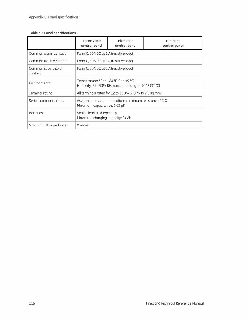
Appendix D: Panel specifications
116 FireworX Technical Reference Manual
Table 30: Panel specifications
Three-zone control panel
Five-zone control panel
Ten-zone control panel
Common alarm contact Form C, 30 VDC at 1 A (resistive load)
Common trouble contact Form C, 30 VDC at 1 A (resistive load)
Common supervisory contact
Form C, 30 VDC at 1 A (resistive load)
Environmental Temperature: 32 to 120 °F (0 to 49 °C) Humidity: 5 to 93% RH, noncondensing at 90 °F (32 °C)
Terminal rating All terminals rated for 12 to 18 AWG (0.75 to 2.5 sq mm)
Serial communications Asynchronous communications maximum resistance: 13 Ω Maximum capacitance: 0.03 µF
Batteries Sealed lead acid type only Maximum charging capacity: 24 Ah
Ground fault impedance 0 ohms
FireworX Technical Reference Manual 117
Appendix E Default event codes
Summary
This appendix provides a list of the default event codes that the dialer uses to transmit event activation and restoration codes.
Content
Default Contact ID event codes • 118 Default 4/2 event codes • 119
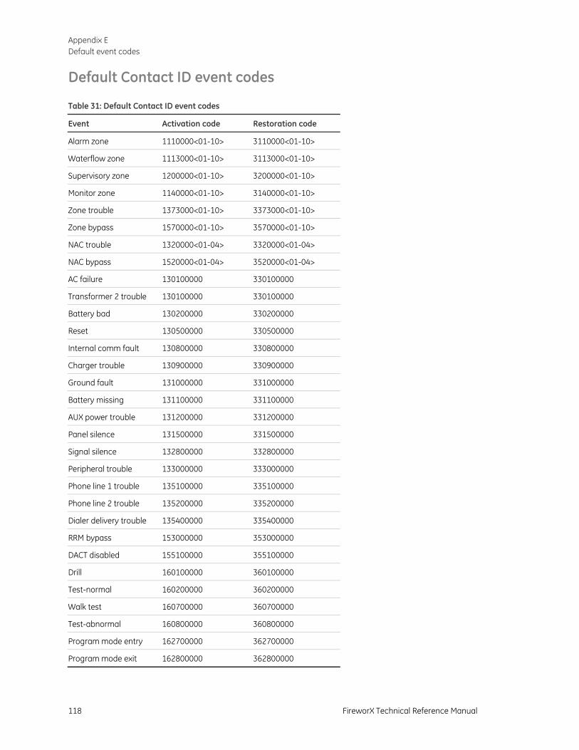
Appendix E Default event codes
118 FireworX Technical Reference Manual
Default Contact ID event codes Table 31: Default Contact ID event codes
Event Activation code Restoration code
Alarm zone 1110000<01-10> 3110000<01-10>
Waterflow zone 1113000<01-10> 3113000<01-10>
Supervisory zone 1200000<01-10> 3200000<01-10>
Monitor zone 1140000<01-10> 3140000<01-10>
Zone trouble 1373000<01-10> 3373000<01-10>
Zone bypass 1570000<01-10> 3570000<01-10>
NAC trouble 1320000<01-04> 3320000<01-04>
NAC bypass 1520000<01-04> 3520000<01-04>
AC failure 130100000 330100000
Transformer 2 trouble 130100000 330100000
Battery bad 130200000 330200000
Reset 130500000 330500000
Internal comm fault 130800000 330800000
Charger trouble 130900000 330900000
Ground fault 131000000 331000000
Battery missing 131100000 331100000
AUX power trouble 131200000 331200000
Panel silence 131500000 331500000
Signal silence 132800000 332800000
Peripheral trouble 133000000 333000000
Phone line 1 trouble 135100000 335100000
Phone line 2 trouble 135200000 335200000
Dialer delivery trouble 135400000 335400000
RRM bypass 153000000 353000000
DACT disabled 155100000 355100000
Drill 160100000 360100000
Test-normal 160200000 360200000
Walk test 160700000 360700000
Test-abnormal 160800000 360800000
Program mode entry 162700000 362700000
Program mode exit 162800000 362800000
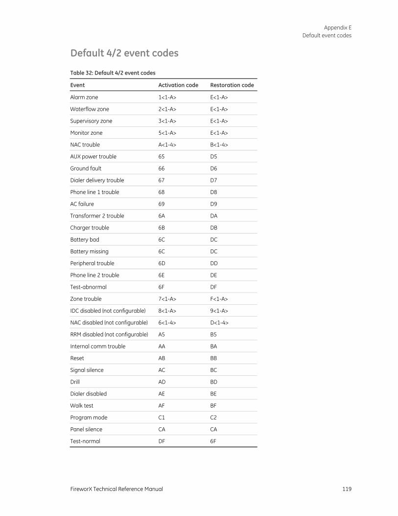
Appendix E Default event codes
FireworX Technical Reference Manual 119
Default 4/2 event codes Table 32: Default 4/2 event codes
Event Activation code Restoration code
Alarm zone 1<1-A> E<1-A>
Waterflow zone 2<1-A> E<1-A>
Supervisory zone 3<1-A> E<1-A>
Monitor zone 5<1-A> E<1-A>
NAC trouble A<1-4> B<1-4>
AUX power trouble 65 D5
Ground fault 66 D6
Dialer delivery trouble 67 D7
Phone line 1 trouble 68 D8
AC failure 69 D9
Transformer 2 trouble 6A DA
Charger trouble 6B DB
Battery bad 6C DC
Battery missing 6C DC
Peripheral trouble 6D DD
Phone line 2 trouble 6E DE
Test-abnormal 6F DF
Zone trouble 7<1-A> F<1-A>
IDC disabled (not configurable) 8<1-A> 9<1-A>
NAC disabled (not configurable) 6<1-4> D<1-4>
RRM disabled (not configurable) A5 B5
Internal comm trouble AA BA
Reset AB BB
Signal silence AC BC
Drill AD BD
Dialer disabled AE BE
Walk test AF BF
Program mode C1 C2
Panel silence CA CA
Test-normal DF 6F

Appendix E Default event codes
120 FireworX Technical Reference Manual
FireworX Technical Reference Manual 121
Index
4
4/2 event codes • 128
A
AC fail delay programming • 35
ack/silence button FSRA10-series remote annunciator • 13
alarm resounding an alarm condition • 17
alarm circuits cross zoned • 41
alarm LED control panel • 6 FSRA10-series remote annunciator • 12 FSRSI • 10
alarm-unverified zone type • 40 alarm-verified zone type • 40 annunciator trouble LED • 7 auto NAC silence timer
operation • 17 automatic signal silence • 46 auxiliary power supply
installing • 27
B
battery calculation • 82 battery trouble LED • 7 buzzer
silencing FSRSI buzzer • 16 silencing panel buzzer • 16
C
cabinet dimensions • 23 installing • 23 semi-flush mount • 23 surface mount • 23
calculations battery • 82 NAC voltage drop • 85
changing the passcode • 33 checklist
installation checklist • 22 city tie NAC type • 45 coder NAC type • 45 common controls • 7 component descriptions • 14 configuring
IDCs • 40 NACs • 45
configuring the dialer account 1 options • 57 account 2 options • 57 dialer mode • 56 dialer options • 59 IDC 4/2 activation codes • 67 IDC event transmit • 63 NAC 4/2 activation codes • 68 NAC event transmit • 64 system 4/2 activation codes • 65 system event transmit • 61
contact ID codes • 126 continuous NAC type • 45 controls and indicators
panel • 6 cross zoned zone type • 41
D
daylight saving time • 55 detecting remote modules • 34 disable
IDC • 18 NAC • 18
disable LED • 6 disable lockout
programming • 35 drill
using the drill command • 19
E
enabling passcode protection • 33 entering local program mode • 31 entering telephone numbers • 53 entering values for panel options • 32 exiting local program mode • 31
Index
122 FireworX Technical Reference Manual
F
F-DACT(F) 4/2 event codes • 128 contact ID • 126 description • 25 installing • 25
Fire Systems Configuration Utility • 31 FSCU • 31 FSRSI
buzzer • 16 lamp test • 76
FSRZI-A lamp test • 76
G
Genesis (AV Sil) NAC type • 45 Genesis NAC type • 45 ground and open tests • 72 ground fault LED • 7
FSRA10-series remote annunciator • 13 FSRSI • 10
I
IDC disable • 18 enabling • 18
IDC alarm LED • 8 IDC class • 41 IDC code digit 1 • 42 IDC code digit 2 • 42 IDC code digit 3 • 42 IDC code digit 4 • 42 IDC controls and LEDs • 8 IDC disable button • 8 IDC Label • 42 IDC non-latching • 41 IDC RRM relay • 41 IDC service check • 41 IDC supervisory/monitor LED • 8 IDC trouble LED • 8 IDC zone type • 40 installation
checklist • 22 installing
auxiliary power supply • 27 cabinet • 23 F-DACT(F) • 25 remote modules • 24
L
lamp test conducting a panel lamp test • 76 conducting an FSRSI and FSRZI-A lamp test • 76
lamp test button FSRA10-series remote annunciator • 13
lamp test LED • 10 LCD text display • 6 load defaults
description • 69
programming • 69
M
monitor zone type • 41
N
NAC disable • 18 enabling • 18 silencing • 17 voltage drop calculation • 85
NAC class • 46 NAC controls and LEDs • 8 NAC disable button • 8 NAC silenceable • 46 NAC trouble LED • 8 NAC type
city tie • 45 coder • 45 continuous • 45 Genesis • 45 Genesis (AV Sil • 45 temporal (3-3-3) • 45
NFPA 72 compliance statement • 25
O
open and ground tests • 72 operation
operating the panel • 16 overview • 5
overview operation • 5 system • 2
P
panel silencing buzzer • 16
panel controls and indicators • 6 panel operating mode
programming • 35 panel programming
overview • 31 panel silence button • 7 power LED
control panel • 6 FSRA10-series remote annunciator • 12 FSRSI • 10
preventive maintenance • 72 programming
FSCU • 31 load defaults • 69
programming methods • 31
R
receiver compatibility list • 26 remote AC fail zone type • 41 remote disconnect button • 8 remote modules
Index
FireworX Technical Reference Manual 123
installing • 24 remote signal silence/drill zone type • 41 replacement parts • 79 replacing the control fuse • 78 reset button
control panel • 7 FSRA10-series remote annunciator • 13
reset/silence inhibit programming • 35
resetting the panel • 16 restoring panel default settings • 33 RRM multi mode
programming • 36
S
selecting panel options • 32 semi-flush mount
cabinet • 23 service detector LED • 7 setting the system clock • 55 signal silence & drill button
control panel • 7 FSRA10-series remote annunciator • 13
silence/lamp test button • 10 silencing
FSRSI buzzer • 16 notification appliances • 17 panel buzzer • 16
supervisory LED control panel • 6 FSRA10-series remote annunciator • 12 FSRSI • 10
supervisory zone type • 41 surface mount
cabinet • 23 system status LEDs • 6
T
temporal (3-3-3) NAC type • 45 trouble LED
control panel • 6 FSRA10-series remote annunciator • 13
FSRSI • 10 trouble messages
clearing • 77
U
ULC tests • 72
W
walk test audible • 75 overview • 74 using the walk test command • 74
walk test button • 8 waterflow LED • 7 waterflow zone type • 40 waterflow/retard delay
programming • 35 waterflow/supervisory zone type • 41 waterflow-retard zone type • 40 waterflow-retard/supervisory zone type • 40
Z
zone active LEDs FSRA10-series remote annunciator • 12 FSRZI-A • 10 FSRZI-SA • 11
zone trouble LED FSRA10-series remote annunciator • 12
zone types alarm-unverified • 40 alarm-verified • 40 cross zoned • 41 monitor • 41 remote AC fail • 41 remote signal silence/drill • 41 supervisory • 41 waterflow • 40 waterflow/supervisory • 41 waterflow-retard • 40 waterflow-retard/supervisory • 40

Index
124 FireworX Technical Reference Manual


