FSM2 Series - Spindelhubgetriebe.com - Antriebstechnik.eu - Betriebsanleitung - CKD-Senso… ·...
56
SM-385853-A INSTRUCTION MANUAL SMALL SIZE FLOW SENSOR RAPIFLOWⓇ FSM2 Series ● Please read this instruction manual carefully before using this product, particularly the section describing safety. ● Retain this instruction manual with the product for further consultation whenever necessary. 1 st EDITION
-
Upload
duongxuyen -
Category
Documents
-
view
216 -
download
0
Transcript of FSM2 Series - Spindelhubgetriebe.com - Antriebstechnik.eu - Betriebsanleitung - CKD-Senso… ·...

SM-385853-A
INSTRUCTION MANUAL SMALL SIZE FLOW SENSOR RAPIFLOW FSM2 Series Please read this instruction manual carefully
before using this product, particularly the section describing safety.
Retain this instruction manual with the product for further consultation whenever necessary.
1st EDITION

[SM-385853-A] ―1―
Safety precautions
Always read before starting use.
When designing and manufacturing a device using CKD products, the manufacturer is obligated to check that device safety mechanical mechanism, pneumatic control circuit, or water control circuit and the system operated by electrical control that controls the devices is secured. It is important to select, use, handle, and maintain the product appropriately to ensure that the CKD product is used safely. Observe warnings and precautions to ensure device safety. Check that device safety is ensured, and manufacture a safe device.
①This product is designed and manufactured as a general industrial machine part. It must be handled by an operator having sufficient knowledge and experience in handling.
②Use this product in accordance of specifications. Contact CKD when using the product outside the unique specifications range, when using it outdoors, and when using it under the conditions and environment below. Do not attempt to modify or additionally machine the product. (1) Use for special applications requiring safety including nuclear energy, railroad, aviation, ship, vehicle, medical
equipment, or applications coming into contact with beverage or food, amusement equipment, emergency shutoff circuits, press machine, brake circuits, or for safeguard.
(2) Use for applications where life or assets could be adversely affected, and special safety measures are required. ③Observe corporate standards and regulations, etc., related to the safety of device
design and control, etc. ISO 4414, JIS B 8370 (pneumatic system rules) JPAS 005 (policy for pneumatic cylinder use and selection) High Pressure Gas Maintenance Laws Occupational Safety and Sanitation Laws, and other safety rules, association standards and regulations.
④Do not handle, pipe, or remove devices before confirming safety. (1) Inspect and service the machine and devices after confirming safety of the entire system related to this
product. (2) Note that there may be hot or charged sections even after operation is stopped. (3) When inspecting or servicing the device, turn off the energy source (air supply or water supply),
and turn off power to the facility. Discharge any compressed air from the system, and pay enough attention to possible water leakage and leakage of electricity.
(4) When starting or restarting a machine or device that incorporates pneumatic components, make sure that the system safety, such as pop-out prevention measures, is secured.
⑤Observe warnings and cautions on the pages below to prevent accidents.
The Safety cautions are ranked as "DANGER", "WARNING" and "CAUTION" in this section.
Note that some items described as "CAUTION" may lead to serious results depending on the situation. In any case, important information that must be observed is explained.
!
Warning !
When a dangerous situation may occur if handling is mistaken leading to fatal or serious injuries, or when there is a high degree of emergency to a warning. When a dangerous situation may occur if handling is mistaken leading to fatal or serious injuries. When a dangerous situation may occur if handling is mistaken leading to minor injuries or physical damage.
WARNING: !
DANGER:
CAUTION: !
!

[SM-385853-A] -2-
DESIGN AND SELECTION
WORKING FLUID
A flammable fluid must not be used.
WORKING ENVIRONMENT Flammable environment
Do not use the product in flammable gas environment. Since explosion-protection is not taken, explosion or fire may be caused.
WORKING FLUID
This product cannot be used as a business meter. Not conformed to the Measurement Law, do not use the product for the commercial purpose. Use the product as an industrial sensor.
Do not use the product with other than applicable working fluids, or the accuracy can not be guaranteed.
Install a filter, an air dryer and an oil mist filter (micro-alescer) onto the primary side (upstream) of the sensor since the compressed air from the compressor contains drain (water, oil oxide and foreign material, etc.) Mesh (wire net) in a sensor is used to rectify the flow in the pipe. Always install a filter since this mesh is not a filter to remove foreign materials, etc.
<Recommended Circuit>
When using a valve on the primary side of this product, only use an oil-prohibit specification valve. This controller could malfunction or fail if subject to splattering grease or oil, etc.
Please let it evaporate when you use the liquefied gas such as carbon dioxide. When the liquefying gas flows into this product, it causes the breakdown.
WORKING ENVIRONMENT
Corrosive environment Do not use the product in an environment containing corrosive gas such as salphur dioxide, etc.
Ambient temperature, fluid temperature Use the product within the ambient and fluid temperature ranges 0 to 50 。C. Even in the specified temperature range, do not use the product where ambient and fluid temperatures will change suddenly, and form dew condensations.
Maximum working pressure/usage flow range Use the product in accordance with specifications. If used out of the maximum working pressure and working flow range, the product may result in failures.
Drip-proof environment The protective structure of this product is equivalent to IP40. Do not install the product where moisture, salt, dust or swarf is contained, or where pressurized, or depressurized, neither. The product can not be used where the temperature changes suddenly or has high humidity since a failure by dew condensation may be produced in the body.
! DANGER:
! WARNING:
filter
Oil mist filter (micrialescer)
Regulator Air dryer FSM2 series Pneumatics Pressure source

[SM-385853-A] -3-
FLOW UNIT
This controller's flow rate is measured with mass flow not affected by pressure. The unit is l /min, that is the mass flow converted to volumetric flow at 20 ・C 1 barometric pressure (101 kPa).
WITHSTANDING PRESSURE
Withstanding pressure may vary per series. Care must be taken to select
the product.
OVREFLOW
Even if twice as much overflow as each series measuring range is applied to the sensor, it is no problem, however, if dynamic pressure is applied near to the maximum working pressure, (when the pressure applied to the primary side with the secondary side released.), the sensor may fail. When feeding workpieces during leak-age inspection, if dynamic pressure is applied, always provide a by-pass circuit or a needle valve to avoid dynamic pressure applying to the sensor.
ADSORPTION VERIFICATION, etc. When using this product with adsorption verification, etc., select the
flow rate range according to vacuum range and adsorption nozzle diameter. Refer to Page 54 on the attached sheet for [flow rate theory calculation method]
When using this product with adsorption verification, etc., always install an air filter onto the upstream of suction side to prevent suction of foreign materials.
When using this product with adsorption verification, etc., considering atmospheric dew point and ambient tempera-ture of this product, use the product under the conditions that dew condensations will not be formed in the inside of pipe.
When using this product with adsorption verification, etc., response time may delay per pipe volume between this product from adsorption nozzle. In that case, take countermeasures such as, reducing piping volume, etc.
When using the product with vacuum applications such as air absorption, etc., do not bend the tube near the push-in joint section. If stress is applied to the tube near the push in joint, insert the tube into the push-in joint after inserting the insert ring.
When the sensor for adsorption verification is replaced from the pressure sensor (switch) to the flow sensor(switch), in the image (refer to right Fig.), the theory of sensor output (switch output) is reversed.
Pressure sensor (switch) Flow sensor (switch) Setpoint and over ON Setpoint or less ON
Ads
orpt
ion
verif
icat
ion ON
OFFAtmosphericpressure side
High vacuumside
ON
OFFFlow rate 0 side
Flow ratelarge side
Care must be taken since change and modification of sequence program of PLC are required. If source pressure/vacuumis not supplied especially when equipment power turned on, problems must not be created in sequence program, etc., of PLC since flow sensor (switch) maintains [flow rate 0]=[sensor output (switch output) ON].
! CAUTION:

[SM-385853-A] -4-
INSTALLATION & ADJUSTMENT
PIPING
Pipe based on the fluid direction and the direction indicated on the device.
When piping a sensor, refer to the torques below not to apply excessive screw-in and load torques to the port.
[Reference value] Set screw Tightening torque N・m
M5 0.5~1.0 Rc1/8 3~5 Rc1/4 6~8 Rc1/2 16~18
Flash the pipe to remove foreign substances and swarf, etc., in inside of pipe before piping. If many foreign materials and swarf, etc. entrain into the inside, the rectifier and the sensor tip could be damaged.
When piping, apply a spanner on the metal section not to apply forces onto the resin section.
When piping, care must be taken that sealing tape and adhesive must not enter into the inside.
・When winding fluorine resin sealing tape around threads, wind the sealing tape one to two times, leaving two to three threads open at the end of the screw. Press down on the tape to stick it onto threads. When using liquid sealing agent, leave one to two threads open from the end, and avoid applying too much.
Solid・
liquid-sealant Solid・
liquid-sealant
Sealing tape Solid・liquid-sealant
(Good) (Good) (Not Good) (Not Good)
When using the metal body with OUT side released, always connect
a joint, or the port filter may be removed. If a push-in joint is used, the tube must be inserted certainly. Pulls the
tube to check that the tube not be come out. Cut the tube at the right angle with the dedicating knife.
! CAUTION:

[SM-385853-A] -5-
INSTALLATION
The display part uses the LCD. The display becomes difficult to see for the view angle.
This product can be installed with any attitude; vertical, horizontal, right or left.
WIRING
Power supply voltage and outputs must be used with the specified voltage. Applying the voltage more than specified voltage may cause malfunction, damage of sensor, electric shock or fire. Do not apply load more than the rated output. Damage or fire of the output may be caused.
WIRING
Line color must be checked when wiring. Check the wiring color with handling precaution, since improper wire connection may result in damage, failure or malfunction of the sensor.
Insulation of wiring must be checked. Eliminate contact, ground fault and terminal insulation defective with other circuits, or over-current will be admitted into the sensor to damage.
For the power supply to be used, use DC safety power supply insulated form alternating current power supply and in rated range. If power supply is not insulated, electric shock may be created. If power supply is not stabilized, the peak magnitude in summer may exceed the rated value, causing damage of this product, or reducing the accuracy.
! DANGER:
Bracket (separate sales) Model no. : FSM2-LB1 Port size: Push-in joint φ4、6、8、10 Rc1/8、Rc1/4、M5
Bracket (separate sales) Model no. : FSM2-LB2 Port size: Rc1/2
! CAUTION:
! WARNING:
Vertical mount (with bottom thread)
Horizontal mount (with through hole)
Bracket mount (with bracket)

[SM-385853-A] -6-
WIRING
After the connectors are inserted, lay the connector covers over the connectors.
Make sure that stress by forcible bend of pulling is not applies directly to the sensor cable joint.
For wiring, stop control unit/machinery and equipment, and turn off the power supply. Sudden operation may create not anticipated motions, causing a danger. First, attempt energizing test, then set the desired switch data while control unit, machinery and equipment are stopped. Discharge static electricity built in body, tool and equipment before and during work. Use a wire with elasticity as wire for robot connection in the movable part.
Do not use the product out of power supply voltage range. If voltage more than usage range is applied, or if alternating current power (AC100V) applied, causing damage or burn.
This product and wiring must be installed as far away as possible from noise source such as strong electric line, etc. Take other countermeasures for a surge on the power supply line.
Do not short-circuit a load, or causing damage or burn. Use DC safety power supply thoroughly insulated from the AC
primary side for a power supply for the metal body (stainless steel and aluminum bodies) type, while connecting either + or - side on the power supply to F.G. Variable resistor (clamping voltage approximate 40V) is connected between the inside power circuit of metal body type and the metal body to prevent breakdown of the sensor. High potential and insulation resistance tests between the inside power circuit of metal body type and the metal body must not be done. If required, attempt these tests after wiring is disconnected. The excessive electric potential difference between power supply and metals body makes inside parts burn. When electric welding equipment or frame and when creating a short-circuit accident after metal body type installed, connected or wired, transient high and surge voltages may run in ground line or fluid path connected to the components above when welding current runs or when welding, causing a damage. Remove all F.G. connections of the product and electric wiring before work such as electric welding, etc.
AJUSTMENT
If a switch is activated in unstable flow rate state such as a fluid pulsation, etc., unstable operation may be pro-vided. In this case, maintain a sufficient difference between two set-points, or avoid switch setting in the unstable area, then use the product after checking that switching operation be stabilized.
Output accuracy is affected by self exoergics caused by energizing other than temperature characteristics. When using, stand-by time (5 minutes and over after energizing) must be provided.
For self-diagnosis, this product does not conduct flow rate detecting switch operation for proximate 2 seconds immediately after energized. Make a control circuit and programs to ignore signals for approximate 2 seconds after energized.
! WARNING: connector cover

[SM-385853-A] -7-
DURING USE & MAINTENANCE
When an error occurs during operation, turn off power supply immediately, and terminate the operation, and contact to the sales office.
Use the product within range of rated flow. Use the product within range of working pressure. When changing set-points of the output, stop the equip-ment, then
change the set-points, or an accident may occur. A periodic inspection should be done at least once a year, then make
sure that the product be operated properly. Disassembly and modification must not be done or causing a failure.The material of case is resin. Solvent/alcohol/cleaner, etc., must not
be used to remove contamination, etc., or causing a resin to be corroded. Wipe weakened neutral detergent with tightly squeezed waste cloth, etc.
Be careful of reverse current by disconnection/wiring resistance. If other components including another flow sensor are connected to the same power source of the sensor, when switch output line and - side of power line are short-circuited to check operation of input device in the control panel, or if side of power line is disconnected, reverse flow in switch circuit may cause damage.
Main circuit
Test SW or short circuit
Flow sensor
Diode for reverseprevention
Anot
her
com
pone
nt
PL
Cin
put
Control panel
Current fromanother component Disconnection
Preventing damage by reverse current, take the following countermeasures. (1) Avoid concentration to - side power line, and use the wire as fat as
possible. (2) Narrow the number of components to connect to the same power
source of the sensor. (3) Provide a diode on the flow sensor output line in serial to prevent
reverse current. (4) Provide a diode on - side of flow sensor power line to prevent reverse
current.
Be careful of leading of surge current. If the flow sensor shares the power source with inductive load forming surge of a solenoid valve or a relay, etc., when a circuit is disconnected with the inductive load activated, depended with surge absorbing element, surge current may lead to the switch output circuit, causing a damage.
! CAUTION:
[SM-385853-A] -8-
Mai
n ci
rcui
t
ON
PLC
PLC output
Flow sensor
Surge absorbing element(Later installation)
Circuit shutdown by disconnection or emergency stop
Surge absorbing element (Integrated)
Rel
ay
Surge current
SolenoidValve
Take the following countermeasures to prevent damage by surge current leading. (1) Separate output system; inductive load such as solenoid
valve and relay, and input system; flow sensor. (2) If the power source can not be separated, provide surge
suppressor elements to all inductive loads directly. Surge absorbing element connected PLC, etc., merely protect a single component connected.
(3) Furthermore, connect surge suppressor element per power line to protect the product from disconnection.
In
put
com
pone
nt
Inpu
t co
mpo
nent
Inpu
t co
mpo
nent
If components are connected with connectors, when the connector is removed while energized, the output circuit may be damaged. So, always mount or dismount the connector after the power is turned off.
When out of flow rate range, analog output will be provided. [Hi] or [Lo] will be displayed, and The bar display blinks for separated indicator type. However, accuracy is not guaranteed.
Do not push the display part., or causing damage.
CAUTION: !

[SM-385853-A] -9-
INDEX
SMALL SIZE FLOW SENSOR RAPIFLOW FSM2 Series
Manual No. SM-385853-A
1. INSTALLATION
1.1 Piping ·························································································· 11
1.2 Installation··················································································· 12
1.3 Wiring·························································································· 13
1.3.1 Integrated indicator type (FSM2-N series(NPN output))······ 13
1.3.2 Integrated indicator type (FSM2-P series(PNP output)) ······ 14
1.3.3 Separated indicator type (FSM2-A series(analog output))··· 15
2. OPERATION
2.1 Names and functions of display and operation section ·············· 16
2.1.1 Integrated indicator type (FSM2-N/P series) ······················· 16
2.1.2 Separated indicator type (FSM2-A series) ··························· 16
2.2 Function (Integrated indicator type)············································ 17
2.3 Normal mode(Integrated indicator type) ····································· 18
2.3.1 Displaying the integrated flow·············································· 18
2.3.2 Peak hold function ······························································· 18
2.3.3 Set-point verification method ··············································· 19
2.3.4 Key lock / Key unlock function ············································· 19
2.4 Standard setting mode································································ 20
2.4.1 How to enter to standard setting mode································ 20
2.4.2 Setting of switch output function ·········································· 21
2.4.3 Switch output forcible ON mode ·········································· 23
2.4.4 Zero point adjustment ·························································· 23
2.5 Detailed setting mode (Integrated indicator type)······················· 24
2.5.1 How to enter to detailed setting mode ································· 24
2.5.2 Setting of flow direction (Integrated indicator type, Bi-directional type only)·············· 25
2.5.3 Setting of auto reference······················································ 26
2.5.4 Setting of response time ······················································ 29
2.5.5 Setting of display speed······················································· 29
2.5.6 Setting of sub-display··························································· 30
2.5.7 Setting of display color························································· 30
2.5.8 Hysteresis fixed value selection··········································· 31
2.5.9 Setting of flow rate unit ························································ 31
2.5.10 Setting of Eco mode····························································· 32
2.5.11 Reset to the initial setting····················································· 32

[SM-385853-A] -10-
2.5.12 Model number display·························································· 33
3. MAINTENANCE
3.1 Error displays and corrective action ··········································· 34
3.2 TROUBLE SHOOTING······························································· 35
4. PRODUCTS
4.1 Specifications·············································································· 36
4.1.1 Integrated indicator type (FSM2-N/P series) ······················· 36
4.1.2 Separated indicator type (FSM2-A series) ··························· 38
4.2 How to order ··············································································· 40
4.3 Dimensions ················································································· 41
4.3.1 Integrated indicator type (FSM2-N/P series) ······················· 41
4.3.2 Separated indicator type (FSM2-A series) ··························· 44
4.3.3 Integrated indicator type (with bracket)································ 47
4.3.4 Separated indicator type (with bracket) ······························· 48
4.3.5 Bracket ················································································· 50
4.3.6 Cable option········································································· 51
4.4 Internal structure
4.4.1 Resin body (Integrated indicator type)································· 52
4.4.2 Stainless body (Separated indicator type) ··························· 52
4.4.3 Aluminum body (Separated indicator type)·························· 53
5. Technical data
5.1 How to select flow sensor ··························································· 54
Jun.11.2007
[SM-385853-A] -11-
INSTALLATION
1
1. INSTALLATION
1.1 Piping <Caution> Arrange piping so that the flow direction agrees with the direction of the arrow indicated on the sensor body.
Flash the pipe to remove foreign substances and swarf, etc., in inside of pipe before piping. When piping a sensor, do not apply excessive screw-in and load torques to the port.
When piping, apply a spanner on the metal section not to apply forces onto the resin section.
[Reference value] Set
screw Tightening torque
N・m M5 0.5~1.0
Rc1/8 3~5
Rc1/4 6~8
Rc1/2 16~18
When piping, care must be taken that sealing tape and adhesive must not enter into the inside. If a push-in joint is used, the tube must be inserted certainly. Pulls the tube to check that the tube
not be come out
Flow direction

[SM-385853-A] -12-
INSTALLATION1
1.2 Installation ・The display part uses the LCD. The display becomes difficult to see for the view angle. ・This product can be installed with any attitude; vertical, horizontal, right or left. The tightening torque
for screws should be 0.5N・m.
Bracket (separate sales) Model no. : FSM2-LB1 Port size: Push-in joint φ4、6、8、10 Rc1/8、Rc1/4、M5
Bracket (separate sales) Model no. : FSM2-LB2 Port size: Rc1/2
Vertical mount(with bottom thread)Horizontal mount
(with through hole)
Bracket mount (with bracket)

[SM-385853-A] -13-
INSTALLATION
1
1.3 Wiring 1.3.1 FSM2-N series(Integrated indicator type, NPN output type)
connector
Mai
n ci
rcui
t
Load
Load
Load
(Brown)Power supply+
(Gray)Analog output
(Black)CH1SW output1
(White)CH2SW output 2
(Blue) Power supply -
+
-
2
3
4
5
1
Mai
n ci
rcui
t
Load
Load
(White)CH2 Input
+
-
2
3
4
5
1(Brown)Power supply+
(Black)CH1 SW output1
(Gray)Analog output
(Blue) Power supply -
Pin No. Line color Content
[1] Brown Power supply (DC 12 to 24V, DC 24V) [2] Black CH1(Switch output 1: max50mA) [3] White CH2(Switch output 2: max50mA or External input)
[4] Gray
Analog voltage output : DC 1 to 5V Connected load impedance 50kΩ and over)
Analog current output : DC 4 to 20mA Connected load impedance 300Ω or less)
[5] Blue 0V (GND)
[1] [2] [3] [4] [5]
(FSM2 side)
CH2 function selected switch output
CH2 function selected external input

[SM-385853-A] -14-
INSTALLATION1
1.3.2 FSM2-P series(Integrated indicator type, PNP output type)
connector
Mai
n ci
rcui
t Load
Load
Load
(Brown)Power supply+
(Gray) Analog output
(Blue) Power supply -
+
-
(Black)CH1 SW output1
(White)CH2SW output 2
2
3
4
5
1
Mai
n ci
rcui
t
Load
Load
(Brown)Power supply+
(Gray)Analog output
(Blue)Power supply -
+
-
(Black)CH1SW output1
(White)CH2Input
2
3
4
5
1
CH2 function selected switch output
CH2 function selected external input
Pin No. Line color Content
[1] Brown Power supply (DC 12 to 24V, DC 24V) [2] Black CH1(Switch output 1: max50mA) [3] White CH2(Switch output 2: max50mA or External input)
[4] Gray
Analog voltage output : DC 1 to 5V Connected load impedance 50kΩ and over)
Analog current output : DC 4 to 20mA Connected load impedance 300Ω or less)
[5] Blue 0V (GND)
[1] [2] [3] [4] [5]
(FSM2 side)

[SM-385853-A] -15-
INSTALLATION
1
1.3.3 FSM2-A series(Separated indicator type)
connector
Pin No. Line color Content
[1] Brown Power supply (DC 12 to 24V, DC 24V)
[2] Black
Analog voltage output : DC 1 to 5V Connected load impedance 50kΩ and over)
Analog current output : DC 4 to 20mA Connected load impedance 300Ω or less)
[3] White Non connection [4] Blue 0V (GND)
Mai
n ci
rcui
t Load
(Brown)Power supply+
(Black)analog output
(white)NC
(Blue)Power supply -
+
-
[1] [2] [3] [4]
(FSM2 side)

[SM-385853-A] -16-
OPERATION2
2. OPERATION
2.1 Names and functions of display and operation section 2.1.1 Integrated indicator type (FSM2-N/P series)
2.1.2 Separated indicator type (FSM2-A series)
Flow rate One-direction type Bi-directional type 0%F.S.
+60%F.S. (Forward)
+120%F.S. (Forward)
Blinks
-60%F.S. (Reverse)
-120%F.S. (Reverse)
Blinks
Mode key Press to enter each setting mode Press to advance setting mode Press to return to flow rate display Press to cancel peak hold operation
Up key When flow rate is displayed = Displays the CH1 data During peak hold operation =
Displays the maximum value When selecting a mode =
Sets the mode When setting each data =
Down key When flow rate is displayed = Displays the CH2 data During peak hold operation =
Displays the maximum value When setting each data =
Increases the value, etc.
Main display (Green/Red) Displays flow rate, various switch settings. Indication color is selectable.
Sub-display (Green/Red) Displays flow direction, machine status. Indication color is selectable.
Unit display (Green) Displays flow rate unit
1:Switch output indicator (CH1) 2:Switch output indicator (CH2) Lights when switch output (CH1) turns on. Blinks when over current protection is operating
The flowing quantity bar display It lights according to flow rate. Blinks when over current protection is operating
0 20 40 60 80 100 L/min
GAS:
Air, N2
0 20 40 60 80 100L/min
GAS: Air,
-100 -60 -20 0 20 60 100 L/min
GAS:Air,
0 20 40 60 80 100L/min
GAS: Air,
-100 -60 -20 0 20 60 100 L/min
GAS:Air,
0 20 40 60 80 100L/min
GAS: Air,
-100 -60 -20 0 20 60 100 L/min
GAS:Air,
0 20 40 60 80 100L/min
GAS: Air,
-100 -60 -20 0 20 60 100 L/min
GAS:Air,
-100 -60 -20 0 20 60 100 L/min
GAS:Air,
0 20 40 60 80 100L/min
GAS: Air,

[SM-385853-A] -17-
OPERATION
2
2.2 Function (FSM2-N/P series) Normal mode (Refer to Page 18 for the operation.)
Item Description Setting at shipping out of factory
Flow rate display Instantaneous flow rate is displayed. -
Integrating function Integrated flow rate is displayed. Instantaneous flow rate
Peak hold function Maximum and minimum flow rate values during the specified periodcan be read.
Peak hold : OFF
Key lock Setting changes are disabled to prevent incorrect operations. Key unlock Error display
function The error state is displayed. -
Standard setting mode (Refer to Page 20 for the operation.)
Item Description Setting at shipping out of factory
Switch output Having 2 pieces of switch output, 7 operation patterns and stop of operation can be set.
OFF
Forcible output Switch output is turned on forcibly to check wiring connection and initial operation of input unit.
-
0 point adjustment Deviation of the display from 0 is corrected Zero
Detailed setting mode (Refer to Page 24 for the operation.)
Item Description Setting at shipping out of factory
Flow direction selection
Only bi-directional type, flow direction can be switched. Bi-direction
CH2 function selection
Sets the CH2 function. Selects “Switch output”, ”External input of auto reference”, or ”External input of integrated reset”.
Switch output
Auto reference function
When CH2 function selected external input of auto reference, setting value of switch output can be taken by external input or key operation.
Auto reference function : OFF
Response time setting
Sets the response time. The response time can be selected from 20ms to 1280ms.
Response time :50msec
Display speed selection
Change the speed of the displayed. Display speed :250msec
Sub-display selection
Change the indication of the sub-display. Selects “Flow direction”, ”Flow rate unit”, or “Working fluid”.
Sub-display
Displayed color selection
Displayed color can be changed. Red when ON Green when OFF
Hysteresis fixed value selection
Sets hysteresis of the window operation mode and the auto ref-erence mode. (8 steps)
Hysteresis:1%FS
Unit selection Flow rate unit can be changed. Standard condition (ANR): Converted to volumetric flow at 20°C
and 1 atmospheric pressure (101kPa). Reference condition (NOR): Converted to volumetric flow at 0°C
and 1 atmospheric pressure (101kPa).(calculation value)
Flow rate unit : ANR
Eco mode setting Current consumption can be lowered. When the product is left for 1 min. without any operation, it’s shift to eco mode.
Eco mode : OFF
Reset setting Return to default settings (factory settings) -

[SM-385853-A] -18-
OPERATION2
2.3 Normal mode (Integrated indicator type) 2.3.1 Displaying the integrated flow
Note: Integration is reset with the external input. See auto reference function.
Note: Integration is also reset when power is turned OFF.
2.3.2 Peak hold function
Note: The screen color at switch ON doesn't change while holding the peak.
mL / min
mL / min mL
Display unit selection
Instantaneous flow rate display. (unit : mL/min、L/min)
Integrated display (unit : mL、L)
<Instantaneous flow rate display.>
Press once
Press once(setting)
mL
<Integrated display>
Integration resetIntegration is reset when the and keys are held down for 2 sec.
Press simultane-ously for 2 sec.
<Instantaneous flow rate display.>
mL / min
Peak hold display
and press simultaneously
mL / min
mL / min mL / min
Being held down Being held down
<Peak value displayed> <Bottom value displayed>
Press once
Reset peak hold function. To instantaneous flow rate display

[SM-385853-A] -19-
OPERATION
2
2.3.3 Set-point verification method
Note: When an external input uses the auto reference function, it doesn't operate.
2.3.4 Key lock / Key unlock function Key lock
Key unlock
Note: Keys are unlocked when the controller is shipped. Lock keys if necessary.
The key lock/unlock state is held even if power is turned OFF.
mL / min
CH1 data display
<Instantaneous flow rate display.>
Being held down
To Instantaneous flow rate display
Separate
CH2 data display
<Lower limit>
<Upper limit> Operation waveform Displays in turn
mL / min 1
mL / min 1
When CH1 selected window operation[1] When CH2 selected external input of integrated reset.
Separate
Being held down
mL / min
<Instantaneous flow rate display.(key unlock)>
and press simultaneously for 1 sec
mL / min
Instantaneous flow rate display (key lock)
mL / min
<Instantaneous flow rate display. (key lock)>
mL / min
<Instantaneous flow rate display (key unlock)>
and press simultaneously for 3 sec.

[SM-385853-A] -20-
OPERATION2
2.4 Standard setting mode 2.4.1 How to enter to standard setting mode
mL / min
<Instantaneous flow rate display.>
Press for 3 sec.
<Switch output>
Press once
<Forcible output function>
Press once
<0 point adjustment>
Press once
To Instantaneous flow rate display
To switch output setting display
Press once(determination)
To forcible output setting display
Press once(determination)
To 0 point adjustment setting display.
Press once(determination)
mL / min
To page 21
To page 23
To page 23
At instantaneous flow rate display, press key for 3 sec. to enter to standard
setting mode.

[SM-385853-A] -21-
OPERATION
2
2.4.2 Setting of switch output function
Switch output setting display
<Switch output OFF> <Window operation①> <Window operation②>
<Hysteresis operation①>
<Hysteresis operation②> <Integrated flow output①><Integrated flow output②>
<Integrated flow pulse output>
CH1 operation mode change
Press once(determination)
CH1 ON/OFF data setting
mL / min mL / min
<ON set-point> <OFF set-point>
Count up
Count down
Press onse
Press once. (determination)
CH2 operation mode change (Set same as CH1)
CH2 ON/OFF data setting (Set same as CH1)
Press once (determination)
Press once. (determination)
To Instantaneous flow rate display
Press key once to increase by one figure and press it continuously to keep set figure increased.
Press or key to select operation mode. Press key to set.
Press key once to decrease by one figure and press it continuously to keep set figure decreased.

[SM-385853-A] -22-
OPERATION2
Switch output Having 2 pieces of switch output, 7 operation patterns and stop of operation can be set.
No. Operation pattern Description Operation waveform LCD display
1
Switch output OFF Switch output OFF
2 Window operation[1] (Range inside ON)
Note1
The switch turns ON when the level is within the des-ignated flow rate range.
3 Window operation[2] (Range out ON)
Note1
The switch turns ON when the level is not within the designated flow rate range.
4 Hysteresis operation[1] (Flow rate small side ON)
ON when lower than set point. Hysteresis can be arbitrarily set.
5 Hysteresis operation[2] (Flow rate large side ON)
ON when higher than set point. Hysteresis can be arbitrarily set.
6 Integrated output[1] (On when higher than
set integration)
The switch turns ON at the set integrated flow.
7 Integrated output[2] (Off when higher than
set integration)
The switch turns OFF at the set integrated flow.
8 Integrated pulse The integrated pulse is output during integration. See specifications for de-tails on the pulse output rate.
Note1: Hysteresis is provided on upper and lower limit of window operation automatically. The hysteresis can be fixed in 8 steps. Refer to <2.5.8.Hysteresis fixed value selection> in <De-
tailed setting mode>. Note2:Refer to <Pulse output rate> in <4.1. Specifications>.
Flow rate
ON
OFF
Lower limit Upper limit
Flow rate
ON
OFF
Upper limitLower limit
Flow rate
ON
OFF
Lower limit Upper limit
Flow rate
ON
OFF
Upper limitLower limit
Integrated flow rate
ON
OFF
Set point
Integrated flow rate
ON
OFF
Set point
Integrated flow rate
ON
OFF
Pulse rateNote2
40msec
Flow rate
ON
OFF

[SM-385853-A] -23-
OPERATION
2
2.4.3 Switch output forcible ON mode
2.4.4 Zero point adjustment
Note: Always adjust 0 point without flow. Note: If fluid flows during zero adjustment setting, “E 02” is indicated. Note: The offset value is different to display it by the operation processing value from an actual
flowing quantity value.
Forcible output setting display
To Instantaneous flow rate display Press once
2
1
1 2
0 point adjustment setting display.
To Instantaneous flow rate display
Press once(determination) Press once
Press simultaneously
(Adjusted value reading) Adjustment value display
(CH1 output ON)
Being held down
Being held down
Being held down
(CH2 output ON)
(CH1 and CH2 output ON)

[SM-385853-A] -24-
OPERATION2
2.5 Detailed setting mode 2.5.1 How to enter to detailed setting mode
mL / min
<Instantaneous flow rate display>
Press for 8 sec
<Flow direction selection> (only bi-directional type)
Press once
<Auto reference function>
To flow direction setting display
Press once (determination)
To auto reference setting display
Press once (determination)
mL / m
Press once
<Response time setting>
To response time setting display
Press once (determination)
Press once
<Display speed selection>
To display speed setting display
Press once (determination)
Press once
<Sub-display selection>
To sub-display setting display
Press once (determination)
Press once
<Displayed color selection>
To displayed color setting display
Press once (determination)
Press once
<Hysteresis fixed value selection>
To hysteresis fixed value
Press once (determination)
Press once
<Unit selection>
To flow rate unit setting display
Press once (determination)
Press once
Setting value
Setting value
Setting value す
Setting value す
Setting value
Setting value す
Setting value す
Setting value す
To flow rate display
<Eco mode setting>
To eco mode setting display
Press once (determination)
Press once
<Reset setting>
To reset setting display
Press once
<Model number display>
To model number display
Press once
Setting value
To page 25
To page 26
To page 29
To page 29
To page 30
To page 30
To page 31
To page 31
To page 32
To page 32
To page 33
Press once (determination)
Press once (determination)
At instantaneous flow rate display, press key for 8 sec. to enter to detailed setting mode.

[SM-385853-A] -25-
OPERATION
2
2.5.2 Setting of flow direction(Integrated indicator type, Bi-directional type only)
Flow direction can be switched. Press or key to select flow direction. Press key to set.
Flow direction
Flow direction LCD display Analog output characteristics <Bi-directional>
<One-direction (Forward)>
<One-direction (Reverse)>
The arrow changes according to flow direction
When reverse flow, “-“is indicated
(L/min)
Ana
log
outp
ut
-F.S.flow rate 0 F.S.flow rate
5 20
3 12
1 4
(V) (mA)
(L/min)
Ana
log
outp
ut
0 F.S.flow rate
5 20
3 12
1 4
(V) (mA)
(L/min)
Ana
log
outp
ut
0 F.S.flow rate
5 20
3 12
1 4
(V) (mA)
Flow direction setting display
Setting of flow direction
<One-direction (Forward)> <One-direction (Reverse)> <Bi-directional>
Press once (determination)
To Instantaneous flow rate display
Note: When flow direction is changed, other setting value is cleared.

[SM-385853-A] -26-
OPERATION2
2.5.3 Setting of auto reference When CH2 function selected external input of auto reference, setting value of switch output can be
taken by external input or key operation. The set point takes the flow rate when external input is turned on (or key operation). When auto reference is executed, the switch setting of CH2 becomes invalid.
Press or key to select CH2 function. Press key to set.
Auto reference setting display
<Switch output> <External input of integrated reset> <Auto reference>
To instantaneous flow rate display
Press once (determination)
To setting of CH2 switch output
Press once(determination)
Press once (determination) )
Setting of CH2 function
Reference method selection (Key operation / External input)
<Button operation> <External input>
Press once (determination)
Select input setpoints
<1-point input> <2-point input>
Press once (determination)
Press once(determination)
Input point selection(1-point input) Input point selection(2-point input)
<Flow rate large side ON> <Flow rate small side ON> <Flow rate large side ON> <Flow rate small side ON>
<Range outside ON> <Range inside ON> Press once (determination)
To flow rate display
mL / min

[SM-385853-A] -27-
OPERATION
2
How to take set point by key operation
・1-point input : The set point takes the flow rate when press key for 2 sec. ・2-point input : The upper limit takes the flow rate when press key for 2 sec.
The lower limit takes the flow rate when press key for 2 sec. ・After taking, the set point is displayed.
How to take set point by external input ・1 point input : The set point takes the flow rate when external input is turned on (keep approx. 40msec.). ・2 points input : The set point takes the flow rate when external input is turned on (keep approx. 40msec.).
The big and small relations between latest two points are compared, upper limit and lower limit are distin-guished automatically.
(Example)
・After taking, the set point is displayed. Also the pulse is output from CH1 for the taking confirmation. ・The set point value is cleared if power is turned OFF.
Input point(mL/min) Upper limit(mL/min) Lower limit(mL/min)
Initial value 0 0 1st 123 0 123 2nd 234 123 234 3rd 45 45 234 4th 345 45 345 5th 456 345 456

[SM-385853-A] -28-
OPERATION2
Auto reference
Points of input
Operation pat-tern name Description Operation waveform LCD display
1-point input[1] (Flow rate
large side ON)
ON when higher than input point.Set-point=input point
1 point (1-P) 1-point input[2]
(Flow rate small side ON)
OFF when higher than input point. Set-point=input point
2-point input[1] (Flow rate
large side ON)
ON when higher than centre value of two input points (Set-point: )
2-point input[2] (Flow rate
small side ON)
OFF when higher than centre value of two input points (Set-point: )
2-point inside (Range inside
ON)
ON when flow rate level is within two input points. (Set-point1:input point1) (Set-point2:input point2)
2 points (2-P)
2-point outsid (Range outside
ON)
OFF when flow rate level is (Set-point1:input point1) (Set-point2:input point2)
Flow rate
ON
OFF
Set-point
Flow rate
ON
OFF
Set-point
Flow rate
ON
OFF
Set-point Set-point
Flow rate
ON
OFF
Set-point Set-point
Flow rate
ON
OFF
Set-point Set-point
Flow rate
ON
OFF
Set-point Set-point
(Input1+Input2) 2
(Input1+Input2) 2

[SM-385853-A] -29-
OPERATION
2
2.5.4 Setting of response time
2.5.5 Setting of display speed
Display speed setting display
Setting of display speed
<250msec> <500msec> <1000msec>
To Instantaneous flow rate display
Press once(determination)
Response time setting display
Setting of response time
…
Symbol Response time
SP 1 20msec SP 2 40msec SP 3 80msec SP 4 160msecSP 5 320msecSP 6 640msecSP 7 1280msec
To Instantaneous flow rate display
Press once(determination)
Press or key to select response time. Press key to set.
Press or key to select display speed. Press key to set.

[SM-385853-A] -30-
OPERATION2
2.5.6 Setting of sub-display
2.5.7 Setting of display color
Sub-display setting display
<Flow direction> <Flow rate unit> <Working fluid>
Setting of sub-display
To Instantaneous flow rate display
Press once(determination)
Display color setting display
Setting of display color
To Instantaneous flow rate display
Press once(determination)
<Always red> <Always green> Red when ON Green when OFF
Red when OFF Green when ON
mL / min
Main display shows the state of CH1. Sub display shows the state of CH2
Press or key to select sub-display. Press key to set.
Press or key to select display color. Press key to set.

[SM-385853-A] -31-
OPERATION
2
2.5.8 Hysteresis fixed value selection
2.8.9 Setting of flow rate unit
Flow rate unit setting display
Setting of flow rate unit
To Instantaneous flow rate display
Press once(determination)
<ANR: Standard condition> <NOR: Reference condition>
Note: NOR display is calculation value.
Hysteresis fixed value setting
Hysteresis fixed value selection
To Instantaneous flow rate display
Press once(determination)
…
<Approx.1%FS> <Approx.2%FS> <Approx.8%FS>
When window operation or auto reference is selected.
Press or key to select eco mode. Press key to set.
Press or key to select eco mode. Press key to set.

[SM-385853-A] -32-
OPERATION2
2.5.10 Setting of Eco mode
2.5.11 Reset to the initial setting
Eco mode setting display
Setting of Eco mode
Press once(determination)
mL / min L About 1 min. later
Eco mode ON : If any key is not carried out for approx. 1 min., the display is turned off. Press any key to show the indication.
<Eco mode OFF> <Eco mode ON>
Reset setting
To Instantaneous flow rate display
Press once(determination)
Reset setting display
<Reset is not executed> <Reset is executed>
Setting at shipping out of factory
Item Setting at shipping out of factory Switch out put OFF Zero adjustment value Zero Integrating flow rate value Zero Flow direction (bi-directional type only) Bi-direction Auto reference (CH2 setting) Switch output Response time 20msec Display speed 250msec Sub-display Flow direction display Displayed color ON: Red (OFF: Green) Hysteresis 1%FS Flow rate unit ANR Eco mode OFF
Press or key to select eco mode. Press key to set.
Press or key to select reset setting. Press key to set.

[SM-385853-A] -33-
OPERATION
2
2.5.12 Model number display
Model number display
To instantaneous flow rate display
Press once.
mL / min
<Flow rate unit & flow direction>
<0 point adjustment value>
<Model number> <Full scale flow rate>
<Working fluid> Ai: Air, N2 Ar: Argon C2: Carbon dioxide
<Switch output> N: NPN Output P: PNP Output
Model number display
Press or key to select reset setting. Press key to set.

[SM-385853-A] -34-
MAINTENANC3
3. MAINTENANCE
3.1 Error displays and corrective action
Integrated indicator type
Separated indicator type
Error indication Cause Corrective action If fluid flows during zero ad-
justment setting, “E 02” is indicated.
Please check that fluid doesn’t flow at the time of zero adjustment setting.
An error occurred during EEPROM reading or writing.
Contact your nearest CKD Sales Office or dealer.
An error occurred during memory reading or writing.
Contact your nearest CKD Sales Office or dealer.
Reading exceeds the upper limit of detection range.
Reduce the flow.
Sensor chip is broken. Replace FSM2.
Reading exceeds the lower limit of detection range.
Reduce the flow.
Sensor chip is broken. Replace FSM2.
Switch output indi-cator is blinking
Switch output over current protection circuit is activated.
Check whether load current exceeds the rating, correctly connect the controller, and turn power ON again.
Error indication Cause Corrective action The third from the left blinks. An error occurred during
EEPROM reading or writing. Contact your nearest CKD Sales Office or dealer.
The fourth from the left blinks. An error occurred during memory reading or writing.
Contact your nearest CKD Sales Office or dealer.
Reading exceeds the upper limit of detection range.
Reduce the flow. <One-direction> Blinking of all
<Bi-directional> Half the left blinking
Sensor chip is broken. Replace FSM2.
Reading exceeds the lower limit of detection range.
Reduce the flow. <One-direction> The leftmost blinking
<Bi-directional> Half the left blinking
Sensor chip is broken. Replace FSM2.

[SM-385853-A] -35-
MAINTENANC3
3.2 Troubleshooting
Trouble Cause Corrective action
Breakage of wire. Replace FSM2. Recheck/repair external wiring.
Wrong connection of power source.
Connect the rated power source correctly.
Malfunction caused by noise. Keep FSM2 main body and cable away from noise source.
Output circuit is broken. Replace FSM2.
No flow display (No analog output)
FSM2 is broken. Replace FSM2. Flow display remains 0. (Analog output remains 1V or 3V)
Flow path clogged by foreign matter.
Remove foreign matter and install filter at primary side of FSM2.
Leakage Check and correct piping. Foreign matter sticking to sensor chip. Replace FSM2.
Flow display does not reach 0. (Analog output does not make 1V or 3V) Malfunction caused by noise. Keep FSM2 main body and cable
away from the noise source. Sensor chip is broken. Replace FSM2. Foreign matter sticking to sensor chip. Replace FSM2. Poor precision
Malfunction caused by noise. Keep FSM2 main body and cable away from the noise source. Reduce pulsation by installing tank, etc. Change the response time. Change the display speed.
Pulsation of air. Fault in power source (not enough voltage/capacity) Pulsation of air.
Change the hysteresis.
Fault in power source (not enough voltage/capacity)
Supply rated voltage. Provide power source with enough capacity.
Flow display is not sta-ble. (Analog output is not stable. Output is chattering.)
Malfunction caused by noise. Keep FSM2 main body and cable away from noise source.

-36-
PRODUCTS4
[SM-385853-A]
4. PRODUCTS
4.1 Specifications
4.1.1 Integrated indicator type(FSM2-N/P series) Integrated indicator type(Resin / Aluminum body)
Model no.
Descriptions Integrated indicator type ( Resin / Alum inum body)
FSM2-[*1][*2][*3][*4]-[*5] Full scale flow rate 005 010 020 050 100 200 500 101 201 501 102
005 500m L/m in 010 1L/m in 020 2L/m in 050 5L/m in 100 10L/m in 200 20 L/m in 500 50 L/m in 101 100 L/m in 201 200 L/m in 501 500 L/m in
Full scale flow rate
Note 1 *4
102 1000 L/m in H04 φ 4 push-in / resin H06 φ 6 push-in / resin H08 φ 8 push-in / resin H10 φ 10 push-in/ resin
Poet size/ Body
m aterial *5
A15 Rc1/2 / alum inum Type of d isplay Dual (2×4-digit 7-segm ent) Two-color LCD
F 0 to500
mL/min
0 to1000mL/min
0 to2.00
L/m in
0 to5.00
L/m in
0 to10.00L/m in
0 to20.0
L/m in
0 to50.0L/m in
0 to 100.0 L/m in
0 to 200
L/m in
0 to 500
L/m in
0 to1000L/m inFlow
rate range
*3
R
-500to
500mL/min
-1000to
1000mL/min
-2.00to
2.00L/m in
-5.00to
5.00L/m in
-10.00to
10.00L/m in
-20.0to
20.0L/m in
-50.0to
50.0L/m in
-100.0 to
100.0 L/m in
-200 to
200 L/m in
-500 to
500 L/m in
-1000to
1000L/m in
Flow rate display
D isplay resolution 1m L/m in 0.01L/m in 0.1L/m in 1L/m in Flow rate range 9999999m L 99999.99L 999999.9L 9999999L
Display resolution 1m L 0.01L 0.1L 1L Integrating function Pulse output rate 5m L 10m L 0.02L 0.05L 0.1L 0.2L 0.5L 1L 2L 5L 10L
W orking fluid Note 2 C lean air (J IS B 8392-1.1.1 to 5.6.2), Com pressed air (J IS B 8392-1.1.1~ 1.6.2), and N itrogen gasMaxim um working pressure 0.7MPa Minim um working pressure -0.09MPa
W ithstanding pressure 1MPa Am bient tem perature / hum idity 0 to 50°C and 90% RH or less W
orki
ng
cond
ition
s
W orking fluid tem perature 0 to 50°C (to be no dew condensation.) Flow rate range 3 to 100% F.S.
Linearity (d isplay / analog output) ±3% F.S. or less (25°C, 1 atm ospheric pressure) Pressure characteristics ±5% F.S. or less (-0.09 to 0.7MPa, 25°C, 1 atm ospheric criteria)
Tem perature characteristics ±0.2% F.S./°C or less (15 to 35°C, 25°C criteria) Accu
racy
Repeatability ±1% F.S. or less Response tim e Note3 50m s or less
N 2 points (NPN open collector output, 50m A or less, voltage drop 2.4V or less) Switch output *1 P 2 points (PNP open collector output, 50m A or less, voltage drop 2.4V or less) V 1 point (1 to 5V voltage output and connected load im pedance 50kΩ and over) O
utpu
t
Analog output *2 A 1 point (4 to 20m A current output and connected load im pedance 300Ω or less)V DC12/ 24V (10.8 to 26.4V) Power supply voltage note4 *2 A DC24V (21.6 to 26.4V)
Current consum ption Note5 50m A or less Lead wire φ 3.7 AW G26×5 Functions Flow rate display, flow rate display-peak hold, switch output and analog output
Installation attitude Both vertical and horizontal Strait piping section Not required Protective structure IEC standards IP40
Protective circuit Note6 Power supply and switch output reverse connection protections, and switch output load short-circuit protection
H04 Approx. 50g H06 Approx. 50g H08 Approx. 70g H10 Approx. 75g
Mass *4
A15 Approx. 155g Note1: Converted to volumetric flow at 20°C and 1 atmospheric pressure (101kPa)
Note2: When using compressed air, use clean air complying with JIS B 8392-1:2003 class over 1.1.1 to 1.6.2. Compressed air from the compressor contains drainage (water, oxidized oil, foreign matter, etc.). Install a filter(filtration rating:5µm), air dryer(minimum pressure dew point 10 or less) and oil mist filter(maximum oil concentration 0.1mg/m3) on the primary side of the product to maintain product function.
When using for purposes other than compressed air, use dry gas that does not contain corrosive elements such as chlorine, sulfur or acids, and clean gas that does not contain dust or oil mist.
Note3: The response time can be selected from 50ms to 1.5s. Note4: Current consumption is different according to the state of the load. Note5: This product’s protective circuit is effective only for specific incorrect connections and load short-circuits. It does not necessarily provide protection for all
incorrect connections. No.te6: Integrated flow value is reset by turning power off.

-37-
PRODUCTS
4
[SM-385853-A]
Integrated indicator type (Stainless body)
Note1: Converted to volumetric flow at 20°C and 1 atmospheric pressure (101kPa) Note2: When using compressed air, use clean air complying with JIS B 8392-1:2003 class over 1.1.1 to 1.6.2. Compressed air from the compressor contains
drainage (water, oxidized oil, foreign matter, etc.). Install a filter(filtration rating:5µm), air dryer(minimum pressure dew point 10 or less) and oil mist filter(maximum oil concentration 0.1mg/m3) on the primary side of the product to maintain product function.
When using for purposes other than compressed air, use dry gas that does not contain corrosive elements such as chlorine, sulfur or acids, and clean gas that does not contain dust or oil mist.
Note3: The response time can be selected from 50ms to 1.5s. Note4: Current consumption is different according to the state of the load. Note5: This product’s protective circuit is effective only for specific incorrect connections and load short-circuits. It does not necessarily provide protection for all
incorrect connections. No.te6: Integrated flow value is reset by turning power off.
Model no.
Descriptions Integrated indicator type (Stainless body)
FSM2-[*1][*2][*3][*4]-[*5][*6] Full scale flow rate 005 010 020 050 100 200 500 101 201
005 500m L/min 010 1L/min 020 2L/min 050 5L/min 100 10L/min 200 20 L/m in 500 50 L/m in 101 100 L/min
Full scale flow rate
Note 1 *4
201 200 L/min
S06 Rc1/8 / Stainless
(only Air, Ar)
S08 Rc1/4 / Stainless
(only Air, Ar)
Poet size/ Body
material *5
SM5 M5 / Stainless (order made)
(only Air,
Ar)
Type of display Dual (2×4-digit 7-segm ent) Two-color LCD
F 0 to 500
mL/min
0 to 1000mL/min
0 to 2.00
L/m in
0 to 5.00
L/min
0 to 10.00L/min
0 to 20.0
L/min
0 to 50.0
L/min
0 to 100.0L/m in
0 to 200
L/m inFlow rate
range *3
R
-500 to
500 mL/min
-1000to
1000mL/min
-2.00to
2.00 L/m in
-5.00to
5.00 L/min
-10.00to
10.00L/min
-20.0 to
20.0 L/min
-50.0 to
50.0 L/min
-100.0 to
100.0L/m in
-200 to
200 L/m in
Flow rate display
Display resolution 1m L/min 0.01L/min 0.1L/min 1m L/min
Flow rate range 9999999mL 99999.99L 999999.9L 9999999m L
Display resolution 1m L 0.01L 0.1L 1m L Integrating function
Note 6 Pulse output rate 5m L 10m L 0.02L 5m L 10m L 0.02L 5m L 10m L 2L
Blank Clean air (JIS B 8392-1.1.1 to 5.6.2), Compressed air (JIS B 8392-1.1.1~1.6.2), and Nitrogen gasAR Argon Working fluid
Note 2 *6 C2 Carbon dioxide
Maxim um working pressure 1.0MPa Minimum working pressure -0.09MPa
W ithstanding pressure 1.5MPa Am bient tem perature / humidity 0 to 50°C and 90%RH or less
Wor
king
co
nditi
ons
Working fluid tem perature 0 to 50°C (to be no dew condensation.) Flow rate range 3 to 100%F.S.
Linearity (display / analog output) ±3%F.S. or less (25°C, 1 atmospheric pressure) Pressure characteristics ±5%F.S. or less (-0.09 to 0.7MPa, 25°C, 1 atmospheric criteria)
Tem perature characteristics ±0.2%F.S./°C or less (15 to 35°C, 25°C criteria) Accu
racy
Repeatability ±1%F.S. or less Response tim e Note3 50m s or less
N 2 points (NPN open collector output, 50mA or less, voltage drop 2.4V or less)Switch output *1 P 2 points (PNP open collector output, 50mA or less, voltage drop 2.4V or less) V 1 point (1 to 5V voltage output and connected load impedance 50kΩ and over)O
utpu
t
Analog output *2 A 1 point (4 to 20mA current output and connected load im pedance 300Ω or less)V DC12/24V (10.8 to 26.4V) Power supply voltage
note4 *2 A DC24V (21.6 to 26.4V)
Current consum ption Note5 50m A or less Lead wire φ3.7 AW G26×5 Functions Flow rate display, flow rate display-peak hold, switch output and analog output
Installation attitude Both vertical and horizontal Strait piping section Not required Protective structure IEC standards IP40
Protective circuit Note6 Power supply and switch output reverse connection protections, and switch output load short-circuit protection
S06 Approx. 95g S08 Approx. 115g Mass *5 SM5 Approx. 140g

-38-
PRODUCTS4
[SM-385853-A]
4.1.2 Separated indicator type(FSM2-A series) Separated indicator type (Resin / Aluminum body)
Model no.
Descriptions Separated indicator type ( Resin / Aluminum body)
FSM2-A[*1][*2][*3]-*4] Full scale flow rate 005 010 020 050 100 200 500 101 201 501 102
005 500mL/min
010 1L/min
020 2L/min
050 5L/min
100 10L/min
200 20 L/min
500 50 L/min
101 100 L/min
201 200 L/min
501 500 L/min
Full scale flow rate
Note 1 *3
102 1000 L/min
H04 φ4 push-in / resin
H06 φ6 push-in / resin
H08 φ8 push-in / resin
H10 φ10 push-in/ resin
Poet size/ Body
material *4
A15 Rc1/2 / aluminum
F One-direction Flow direction *2 R Bi-directional
Working fluid Note 2 Clean air (JIS B 8392-1.1.1 to 5.6.2), Compressed air (JIS B 8392-1.1.1~1.6.2), and Nitrogen gasMaximum working pressure 0.7MPa Minimum working pressure -0.09MPa
Withstanding pressure 1MPa Ambient temperature / humidity 0 to 50°C and 90%RH or less W
orki
ng
cond
ition
s
Working fluid temperature 0 to 50°C (to be no dew condensation.) Linearity (display / analog output) ±3%F.S. or less (25°C, 1 atmospheric pressure)
Pressure characteristics ±5%F.S. or less (-0.09 to 0.7MPa, 25°C, 1 atmospheric criteria) Temperature characteristics ±0.2%F.S./°C or less (15 to 35°C, 25°C criteria) Ac
cura
cy
Repeatability ±1%F.S. or less Response time 50mA or less Type of display The flowing quantity bar display
V 1 point (1 to 5V voltage output and connected load impedance 50kΩ and over)Output Analog output *1 A 1 point (4 to 20mA current output and connected load impedance 300Ω or less)V DC12/24V (10.8 to 26.4V) Power supply voltage note4 *1 A DC24V (21.6 to 26.4V)
Current consumption Note3 50mA or less Lead wire φ3.7 AWG26×5 Functions Analog-output、The flowing quantity bar display
Installation attitude Both vertical and horizontal Strait piping section Not required Protective structure IEC standards IP40
Protective circuit Note4 Power supply and switch output reverse connection protections, and switch output load short-circuit protection
H04 Approx. 40g H06 Approx. 40g H08 Approx. 60g H10 Approx. 65g
Mass *4
A15 Approx. 145g Note1: Converted to volumetric flow at 20°C and 1 atmospheric pressure (101kPa)
Note2: When using compressed air, use clean air complying with JIS B 8392-1:2003 class over 1.1.1 to 1.6.2. Compressed air from the compressor contains drainage (water, oxidized oil, foreign matter, etc.). Install a filter(filtration rating:5µm), air dryer(minimum pressure dew point 10 or less) and oil mist filter(maximum oil concentration 0.1mg/m3) on the primary side of the product to maintain product function.
When using for purposes other than compressed air, use dry gas that does not contain corrosive elements such as chlorine, sulfur or acids, and clean gas that does not contain dust or oil mist.
Note3: Current consumption is different according to the state of the load. Note4: This product’s protective circuit is effective only for specific incorrect connections and load short-circuits. It does not necessarily provide protection for all
incorrect connections.

-39-
PRODUCTS
4
[SM-385853-A]
Separated indicator type (Stainless body)
Note1: Converted to volumetric flow at 20°C and 1 atmospheric pressure (101kPa) Note2: When using compressed air, use clean air complying with JIS B 8392-1:2003 class over 1.1.1 to 1.6.2. Compressed air from the compressor contains
drainage (water, oxidized oil, foreign matter, etc.). Install a filter(filtration rating:5µm), air dryer(minimum pressure dew point 10 or less) and oil mist filter(maximum oil concentration 0.1mg/m3) on the primary side of the product to maintain product function.
When using for purposes other than compressed air, use dry gas that does not contain corrosive elements such as chlorine, sulfur or acids, and clean gas that does not contain dust or oil mist.
Note3: Current consumption is different according to the state of the load. Note4: This product’s protective circuit is effective only for specific incorrect connections and load short-circuits. It does not necessarily provide protection for all
incorrect connections.
Model no.
Descriptions Separated indicator type (Stainless body)
FSM2-A[*1][*2][*3]-[*4][*5] Full scale flow rate 005 010 020 050 100 200 500 101 201
005 500mL/min
010 1L/min
020 2L/min
050 5L/min
100 10L/min
200 20 L/min
500 50 L/min
101 100 L/min
Full scale flow rate
Note 1 *3
201 200 L/min
S06 Rc1/8 / Stainless
(only Air, Ar)
S08 Rc1/4 / Stainless
(only Air, Ar)
Poet size/ Body
material *4
SM5 M5 / Stainless (order made)
only Air,
Ar)
F One-direction Flow direction *2 R Bi-direction
Blank Clean air (JIS B 8392-1.1.1 to 5.6.2), Compressed air (JIS B 8392-1.1.1~1.6.2), and Nitrogen gasAR Argon Working fluid
Note 2 *5 C2 Carbon dioxide
Maximum working pressure 1.0MPa Minimum working pressure -0.09MPa
Withstanding pressure 1.5MPa Ambient temperature / humidity 0 to 50°C and 90%RH or less
Wor
king
co
nditi
ons
Working fluid temperature 0 to 50°C (to be no dew condensation.) Linearity (display / analog output) ±3%F.S. or less (25°C, 1 atmospheric pressure)
Pressure characteristics ±5%F.S. or less (-0.09 to 0.7MPa, 25°C, 1 atmospheric criteria) Temperature characteristics ±0.2%F.S./°C or less (15 to 35°C, 25°C criteria) Ac
cura
cy
Repeatability ±1%F.S. or less Response time 50ms or less Type of display The flowing quantity bar display
V 1 point (1 to 5V voltage output and connected load impedance 50kΩ and over)Output Analog output *1 A 1 point (4 to 20mA current output and connected load impedance 300Ω or less)V DC12/24V (10.8~26.4V) Power supply voltage note4 *1 A DC24V (21.6~26.4V)
Current consumption Note3 50mA or less Lead wire φ3.7 AWG26×5 Functions Analog output, The flowing quantity bar display
Installation attitude Both vertical and horizontal Strait piping section Not required Protective structure IEC standards IP40
Protective circuit Note4 Power supply and switch output reverse connection protections, and switch output load short-circuit protection
S06 Approx. 85g S08 Approx.105g Mass *4 SM5 Approx.130g

-40-
PRODUCTS4
[SM-385853-A]
4.2 How to order
FSM2 -A V R 005 - S06 AR 1 B K
[1]Output type [2]Analog output type [3]Flow direction [4]Flow rate range (full scale flow rate)
V 1 to 5V F Bi-directional 005 500 mL/min A Separated indicator type Analog output: 1point A 4 to 20mA R One-directional 010 1 L/min
020 2 L/min 050 5 L/min
N Integrated indicator type Switch output(NPN): 2points Analog output: 1point 100 10 L/min
200 20 L/min 500 50 L/min
P Integrated indicator type Switch output(PNP): 2points Analog outpot: 1point 101 100 L/min
201 200 L/min 501 500 L/min 102 1000 L/min
[5]Port size(body material) [6]Working fluid [7]Cable [8]Bracket [9] Traceability H04 φ4 push-in (resin) Blank Air, Nitrogen gas Blank None Blank None Blank None H06 φ4 push-in (resin) AR Argon 1 1m H08 φ4 push-in (resin) C2 Carbon dioxide 3 3m
B With bracket
H10 φ4 push-in (resin) S06 Rc1/8 (stainless)
T
Traceability certificate,system diagram, inspection results included
S08 Rc1/4 (stainless) A15 Rc1/2 (aluminum)
K Inspection results included
SM5 M5 (stainless)
Combination of flow rate range, port size, and working fluid [5]Port size(body material)
H04 H06 H08 H10 S06 S08 A15 SM5 005 010 020 050 100 200 500 101 201 501
[4]F
low
rate
rang
e
102
Discrete option model
FSM2 - LB1
Symbol Content
LB1 Bracket (for port sizeΦ4,6,8,10, Rc1/8, Rc1/4, M5) LB2 Bracket (for port size Rc1/2) C51 1m (for Integrated indicator type) C53 3m (for Integrated indicator type) C41 1m (for Separated indicator type) C43 3m (for Separated indicator type)
[1]Output type
[2]Analog output type
[5]Port [3]Flow directio
[4]Flow rate [6]Working fluid
[7]Cable
[8]Bracket
[9] Traceability
[6]Working fluid : Air, Nitrogen gas : Argon : Carbon dioxide

-41-
PRODUCTS
4
[SM-385853-A]
4.3 Dimensions
4.3.1 Integrated indicator type (FSM2-N/P series) FSM2-N/P-H04/H06(Flow range:005/010/020/050/100/200/500)
FSM2-N/P-H08/H10(Flow range:500/101/201)
Model No. Port size Dimension (A) FSM2-[ ]-H04[ ] Φ4 push-in 64 FSM2-[ ]-H06[ ] Φ6 push-in 65
Model No. Port size Dimension (A) FSM2-[ ]-H08[ ] Φ8 push-in 70.6 FSM2-[ ]-H10[ ] Φ10 push-in 82.1
2-φ3.4 penetrating
φ4 or φ6 push-in joint
2-M3 depth5
2-φ3.4 penetrating
Φ8 or φ10 push-in joint
2-M3 depth5

-42-
PRODUCTS4
[SM-385853-A]
FSM2-N/P-S06/SM5(Flow range:005/010/020/050/100/200)
FSM2-N/P-S08(Flow range:101/201)
2-φ3.4 penetrating
Rc1/8 or M5
2-M3 depth5
2-φ3.4 penetrating
2-M3 depth5

-43-
PRODUCTS
4
[SM-385853-A]
FSM2-N/P-A15(Flow range:501/102)
2-M3 depth5

-44-
PRODUCTS4
[SM-385853-A]
4.3.2 Separated indicator type (FSM2-A series)
FSM2-A-H04/H06(Flow range:005/010/020/050/100/200)
FSM2-A-H08/H10(Flow range:101/201)
Model No. Port size Dimension (A) FSM2-[ ]-H04[ ] Φ4 push-in 64 FSM2-[ ]-H06[ ] Φ6 push-in 65
2-φ3.4 penetrating
φ4 or φ6 push-in joint
2-M3 depth5
Model No. Port size Dimension (A)FSM2-[ ]-H08[ ] Φ8 push-in 70.6 FSM2-[ ]-H10[ ] Φ10 push-in 82.1
2-φ3.4 penetrating
φ8 or φ10 push-in joint
2-M3 depth5

-45-
PRODUCTS
4
[SM-385853-A]
FSM2-A-S06/SM5(Flow range:005/010/020/050/100/200)
FSM2-A-S08(Flow range:101/201)
2-φ3.4 penetrating
Rc1/8 or M5
2-M3 depth5
2-φ3.4 penetrating
2-M3 depth5

-46-
PRODUCTS4
[SM-385853-A]
FSM2-A-A15(Flow range:501/102)
2-M3 depth5
-47-
PRODUCTS
4
[SM-385853-A]
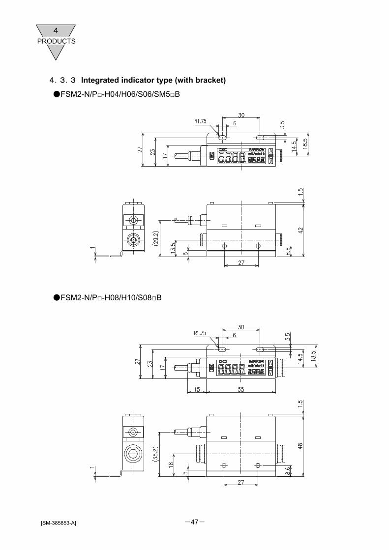
4.3.3 Integrated indicator type (with bracket)
FSM2-N/P-H04/H06/S06/SM5B
FSM2-N/P-H08/H10/S08B

-48-
PRODUCTS4
[SM-385853-A]
FSM2-N/P-A15B
4.3.4 Separated indicator type (with bracket)
FSM2-A-H04/H06/S06/SM5B

-49-
PRODUCTS
4
[SM-385853-A]
FSM2-A-H08/H10/S08B
FSM2-A-A15B

-50-
PRODUCTS4
[SM-385853-A]
4.3.5 Bracket
FSM2-LB1(FSM2-005/010/020/050/100/200/500/101/201)
FSM2-LB2(FSM2-501/102)

-51-
PRODUCTS
4
[SM-385853-A]
4.3.6 Cable option
FSM2-C51/C53 (Integrated indicator type)
FSM2-C41/C43 (Separated indicator type)
Model No. Dimension (L) FSM2-C51 1040±20 FSM2-C53 3040±20
Model No. Dimension (L) FSM2-C41 1040±20 FSM2-C43 3040±20

-52-
PRODUCTS4
[SM-385853-A]
4.4 Internal structure
4.4.1 Resin body (Integrated indicator type)
4.4.2 Stainless body(Separated indicator type)
No. Parts name Material No. Parts name Material [1] Front sheet Polyester film [8] Spacer Stainless steel(SUS304) [2] Case ABS resin [9] Port filter Stainless steel(SUS304) [3] Electron circuit board [10] Port filter Stainless steel(SUS304) [4] Module holder Polyamide resin [11] Sensor tip Semiconductor tip [5] C-ring Stainless steel(SUS304) [12] Stainless body Stainless steel(SUS316) [6] O-ring holder Stainless steel(SUS304) [13] Sensor gasket Fluoro rubber [7] O-ring Fluoro rubber [14] Sensor circuit board Alumina
[1] [2] [3]
[4]
[5]
[6]
[11] [9] [10] [7]
[12]
[13]
[8]
[14]
No. Parts name Material No. Parts name Material [1] LCD cover Acrylic resin [8] Resin body Polyamide resin [2] LCD [9] Sensor tip Semiconductor tip [3] Switch EPDM [10] Rectifier Stainless steel(SUS304)
[4] Substrate spacer Polycarbonate resin [11] Port filter Stainless steel(SUS304)
[5] Module holder Polyamide resin [12] Sensor circuit board Alumina
[6] Push in cartridge joint [13] Electron circuit board
[7] Sensor gasket Fluoro rubber [14] Case ABS resin
[1] [2]
[3]
[4]
[5] [13]
[14]
[6]
[11] [9] [10] [7] [8]
[12]

-53-
PRODUCTS
4
[SM-385853-A]
4.4.3 Aluminum body(Separated indicator type)
No. Parts name Material No. Parts name Material [1] Front sheet Polyester film [8] Spacer Aluminum
[2] Case ABS resin [9] Port filter Stainless steel(SUS304) [3] Electron circuit board [10] Port filter Stainless steel(SUS304) [4] Module holder Polyamide resin [11] Sensor tip Semiconductor tip [5] C-ring Stainless steel(SUS304) [12] Aluminum body Aluminum
[6] O-ring holder Stainless steel(SUS304) [13] Sensor gasket Fluoro rubber [7] O-ring Fluoro rubber [14] Sensor circuit board Alumina
[1] [2]
[3]
[4]
[5] [13]
[14]
[6]
[11] [9] [10] [7] [8]
[12]

-54- [SM-385853-A]
TECHNICAL
5
5. Technical data
5.1 How to select flow sensor • For P1≧1.89P2 (acoustic velocity)
Q=113.2×S×P1
• For P1<1.89P2 (subsonic) Q=226.4×S× P2 (P1-P2)
Q : Flow rate L/min P1 : Primary side absolute pressure MPa P2 : Secondary side absolute pressure MPa S : Ef.sec. area mm2 of Nozzle(pinhole)
Example of calculation When diameter of a nozzle is between 0.1 to 2 and P2 is variable, the calculated flow rate values are shown as followings.
Calculated flow rete value (L/min) P1(MPa) Absolute pressure
P1(MPa) Gauge
pressure
P2(MPa) Absolute pressure
P2(MPa) Gauge
pressure
Acoustic/subsonicvelocity φ0.1 φ0.2 φ0.3 φ0.4 φ0.5 φ0.7 φ1 φ1.5 φ2
0.1013 0 0.0313 -0.07 Acoustic 0.090 0.360 0.810 1.440 2.250 4.411 9.002 20.254 36.007
0.1013 0 0.0413 -0.06 Acoustic 0.090 0.360 0.810 1.440 2.250 4.411 9.002 20.254 36.007
0.1013 0 0.0513 -0.05 Acoustic 0.090 0.360 0.810 1.440 2.250 4.411 9.002 20.254 36.007
0.1013 0 0.0613 -0.04 Velocity 0.088 0.352 0.792 1.408 2.200 4.312 8.800 17.249 35.202
0.1013 0 0.0713 -0.03 Velocity 0.082 0.329 0.740 1.315 2.055 4.028 8.220 16.110 32.878
0.1013 0 0.0813 -0.02 Velocity 0.072 0.287 0.645 1.147 1.792 3.512 7.166 14.046 28.666
Suction
0.1013 0 0.0913 -0.01 Velocity 0.054 0.215 0.483 0.859 1.343 2.631 5.370 10.525 21.480
0.1113 0.01 0.1013 0 Velocity 0.057 0.226 0.509 0.905 1.414 2.772 5.657 11.087 22.626
0.1213 0.02 0.1013 0 Velocity 0.080 0.320 0.720 1.280 2.000 3.920 8.000 15.679 31.998
0.1413 0.04 0.1013 0 Velocity 0.113 0.453 1.018 1.810 2.828 5.543 11.313 22.174 45.252
0.1613 0.06 0.1013 0 Velocity 0.139 0.554 1.247 2.217 3.464 6.789 13.856 27.157 55.423
0.1813 0.08 0.1013 0 Velocity 0.160 0.640 1.440 2.560 4.000 7.840 15.999 31.358 63.996
0.2013 0.1 0.1013 0 Acoustic 0.179 0.716 1.610 2.862 4.472 8.765 17.888 40.248 71.552
0.3013 0.2 0.1013 0 Acoustic 0.268 1.071 2.410 4.284 6.694 13.119 26.774 60.242 107.096
0.4013 0.3 0.1013 0 Acoustic 0.357 1.426 3.209 5.706 8.915 17.474 35.660 80.236 142.641
0.5013 0.4 0.1013 0 Acoustic 0.445 1.782 4.009 7.127 11.137 21.828 44.547 100.230 178.186
Blo
w(L
eaka
ge insp
ection)
0.6013 0.5 0.1013 0 Acoustic 0.534 2.137 4.809 8.549 13.358 26.182 53.433 120.224 213.731
(Caution)
・If piping has a leakage, the actual flow will be larger than the calculated value. Please consider the leakage then selecting flow rate. ・If there is a narrower section then adsorption nozzle diameter in the midway of piping, flow rate will be restricted, so the value will be smaller than the calculated value. Also, adsorption, etc., could not be done. ・The effective sectional area is just reference. If the nozzle is elongated, the effective sectional area will be smaller than opening area of the nozzle. ・Response time is decided by capacity of pipe from adsorption nozzle(pinhole) to flow sensor. When detecting with high speed, reduce capacity in pipe as placing a flow sensor near the adsorption nozzle.
This is a guide of flow range when using a flow sensor as the adsorption/separation verification with adsorption cossle and leakage inspection, etc. The flow rate can be calculated according to effective sectional area of a nozzle(pinhole) and differential pressure between inside and outside of nozzle.
P2 : vacuum
P1 : atmosphericAdsorption
nozzle
P1 : pressurization
P2 : atmospheric
P2 : atmospheric
P1 : pressurization
pinhole