
FSGP 2013 Regulations (Rev A) - American Solar Challenge
36
2013 Regulations Rev A February 8, 2013
Transcript of FSGP 2013 Regulations (Rev A) - American Solar Challenge
2013 Regulations
Rev A February 8, 2013
FSGP 2013 2 of 36
Contents
1. Purpose ...................................................................................................... 4 1.1 Fundamental Vision .....................................................................................................................................4 1.2 Missions .......................................................................................................................................................4
2. Administration ........................................................................................... 4 2.1 Formula Sun Grand Prix (FSGP) Organizers ..............................................................................................4 2.2 Headquarters................................................................................................................................................4 2.3 Officials .........................................................................................................................................................4 2.4 Jury ...............................................................................................................................................................4 2.5 Application of Regulations ............................................................................................................................4 2.6 Supplemental Documents ............................................................................................................................4 2.7 Acceptance of Regulation ............................................................................................................................5 2.8 Interpretation of Regulations ........................................................................................................................5 2.9 Advertising, Promotion, and Publicity ..........................................................................................................5
3. Entries ........................................................................................................ 5 3.1 Entry Registration .........................................................................................................................................5 3.2 Registration Deadlines .................................................................................................................................6 3.3 Vehicle Design Report .................................................................................................................................6 3.4 Grading of Team Reports .............................................................................................................................8 3.5 Team Data ....................................................................................................................................................8 3.6 Participant Registration ................................................................................................................................8 3.7 Faculty Advisor .............................................................................................................................................8 3.8 Communication between FSGP Headquarters and Teams .........................................................................8 3.9 Driver Requirements ....................................................................................................................................8 3.10 Insurance ..................................................................................................................................................9 3.11 Solar Car Markings ...................................................................................................................................9
4. Event Components .................................................................................... 9 4.1 Scrutineering ................................................................................................................................................9 4.2 The Rayce ................................................................................................................................................. 10 4.3 Safety ........................................................................................................................................................ 10 4.4 Withdrawals ............................................................................................................................................... 11
5. Electrical................................................................................................... 11 5.1 Power ........................................................................................................................................................ 11 5.2 Solar Array ................................................................................................................................................ 11 5.3 Energy Storage ......................................................................................................................................... 12 5.4 Protection Circuitry .................................................................................................................................... 12 5.5 Battery Enclosures .................................................................................................................................... 13 5.6 Main Fuse .................................................................................................................................................. 14 5.7 Power Switch............................................................................................................................................. 14 5.8 Cables ....................................................................................................................................................... 15 5.9 Lighting ...................................................................................................................................................... 15 5.10 Horn ....................................................................................................................................................... 15 5.11 Accelerator ............................................................................................................................................ 15 5.12 Control ................................................................................................................................................... 15 5.13 Electrical Shock Hazards ....................................................................................................................... 15 5.14 Water Spray ........................................................................................................................................... 15
6. Mechanical ............................................................................................... 15 6.1 Solar Car Dimensions ............................................................................................................................... 15 6.2 Body Panels .............................................................................................................................................. 16 6.3 Tire and Wheel Requirements .................................................................................................................. 16 6.4 Driver Cockpit ............................................................................................................................................ 16 6.5 Visibility ..................................................................................................................................................... 17 6.6 Ballast ........................................................................................................................................................ 18 6.7 Fasteners ................................................................................................................................................. 18 6.8 Brakes ...................................................................................................................................................... 19 6.9 Parking Brake ............................................................................................................................................ 19
FSGP 2013 3 of 36
6.10 Steering ................................................................................................................................................. 19 6.11 Towing Hardpoint .................................................................................................................................. 20 6.12 Dynamic Stability ................................................................................................................................... 20 6.13 Data Logger ........................................................................................................................................... 20
7. Raycing .................................................................................................... 21 7.1 Briefings .................................................................................................................................................... 21 7.2 Solar Car Configuration ............................................................................................................................. 21 7.3 Team Uniforms .......................................................................................................................................... 21 7.4 Support Vehicles ....................................................................................................................................... 21 7.5 Radios / Communication ........................................................................................................................... 21 7.6 Drivers ....................................................................................................................................................... 21 7.7 Timing ........................................................................................................................................................ 22 7.8 Starts ......................................................................................................................................................... 22 7.9 Charging/Impound ..................................................................................................................................... 22 7.10 Driving Procedures ................................................................................................................................ 22 7.11 Drafting .................................................................................................................................................. 23 7.12 Pushing .................................................................................................................................................. 23 7.13 Breakdowns ........................................................................................................................................... 23
8. Penalties ................................................................................................... 23 8.1 Penalty Times............................................................................................................................................ 23 8.2 Posting of Penalties .................................................................................................................................. 23 8.3 Protests ..................................................................................................................................................... 24 8.4 Time Limit .................................................................................................................................................. 24 8.5 Protest Judgments .................................................................................................................................... 24 8.6 Conduct ..................................................................................................................................................... 24 8.7 Time Penalties........................................................................................................................................... 24
Appendix A ISF Steering Wheel Specifications .......................................... 26
Appendix B ISF Standard Measurement of Seating Angle ......................... 27
Appendix C Reference Standard for Lighting ............................................. 28
Appendix D Mechanical Report Instructions ............................................... 29
Appendix E Electrical System Report Instructions ..................................... 32
Appendix F Battery Approval Form ............................................................. 33
Appendix G Solar Cell Report....................................................................... 34
Appendix H Recommendations .................................................................... 35
Appendix I Revision Table ............................................................................ 36
FSGP 2013 4 of 36
1. Purpose
1.1 Fundamental Vision The Formula Sun Grand Prix (FSGP), hosted by the Innovators Educational Foundation, seeks to promote and celebrate educational excellence and engineering creativity. Fueled by the spirit of friendly competition and teamwork, the FSGP champions the creative integration of technical and scientific expertise across a range of exciting disciplines.
1.2 Missions
1.2.A The support and encouragement of bright young minds to succeed in the fields of engineering, the sciences, mathematics, business, in multi-disciplined experiential learning, and in subsequent careers.
1.2.B To establish an annual event that will promote solar car racing leading to higher engagement in American Solar Challenge events.
2. Administration
2.1 Formula Sun Grand Prix (FSGP) Organizers The Innovators Educational Foundation shall be the official organizers of the FSGP (the “Event”), and shall be responsible for all management oversight and application of the regulations for the Event.
2.2 Headquarters During the Event, a Headquarters will be established at a site appropriate to each function and will assume the management functions for the Event.
2.3 Officials A team of Officials to conduct the Event including all event components will be selected by the organizers. Officials having specific duties shall be announced to the teams through the Briefings.
2.3.A Several Officials will be assigned the role of “Inspector” who have the responsibility to scrutineer the solar cars and enforce the Regulations. The Inspectors will be led by an Official who is the “Chief Inspector / Regulations Manager”.
2.3.B During the event, a team of “Staff” will support the event and will be Officials during the event
2.4 Jury A Jury will be formed to evaluate protests on conformity with these Regulations, to resolve team disputes, and rule on penalty appeals. In addition, the Jury is empowered to decide cases not specifically covered by these Regulations. The Jury will be available to teams during the Rayce. Jury meetings will be held in private. A representative of the team(s) involved may attend deliberations concerning disputes regarding their team, but not the vote. The Jury will consist of:
2.4.A The Event Organizer, who will chair the jury and only vote in the case of a tie
2.4.B The Chief Inspector or designate. All Inspectors may attend the meeting, but only the Chief Inspector may vote
2.4.C Distinguished individuals selected by the Organizers.
2.5 Application of Regulations These Regulations will apply to the Formula Sun Grand Prix (the “Event”), which includes the selection of teams, registration of teams, the inspection of solar cars (“Scrutineering”), and the track competition (the “Rayce”).
2.6 Supplemental Documents Additional documents may be distributed to all teams entered in the Event to supplement these Regulations. These documents will clearly state that they are a supplement to the Regulations and they will have the same force and effect as these Regulations. If there is a conflict between a supplemental document and these
FSGP 2013 5 of 36
Regulations, the document having the later date shall take precedence. The Organizers reserve the right to revise these Regulations at any time.
2.7 Acceptance of Regulation All persons or groups selected to participate in the Event are assumed to know these Regulations. Their participation in the Event will constitute acceptance of them.
2.8 Interpretation of Regulations
2.8.A The only group authorized to interpret the regulations are the Inspectors.
2.8.B Teams shall identify if their question constitutes an Official or Unofficial Interpretation.
2.8.B.1 Official Interpretations will be responded to such that all teams will have visibility to the question and response.
2.8.B.2 Official Interpretations will have the same force and effect as the Regulations.
2.8.B.3 Unofficial Interpretations of the regulations will be kept private between the team and the Inspectors.
2.8.B.4 Unofficial Interpretations will have no force and effect on the Regulations and may be superseded.
2.8.C Prior to Scrutineering:
2.8.C.1 Teams requesting interpretation of the Regulations shall submit their question(s) to the Inspectors through email at: [email protected]
2.8.C.2 All Official Interpretations will be posted to the Internet under “Official Interpretations” on the ASC website.
2.8.D During and after Scrutineering:
2.8.D.1 All Official Interpretations will be announced at Briefings, posted at Headquarters, as well as on the Internet.
2.9 Advertising, Promotion, and Publicity All advertising, sales promotion, and publicity material produced by the teams or their sponsors concerning or referring to the Event will refer prominently to the Event as “Formula Sun Grand Prix”. If in fact a naming sponsor is secured, teams will be required to append the Sponsor Name and to display the entire Event name, i.e. “The Acme – Formula Sun Grand Prix”. All teams, by entering the Event, specifically agree to abide by this regulation. By entering the Event, all teams and team members agree to the use of their names and their likenesses in any publicity materials (brochures, magazines, videos, photographs, etc.) that may be issued by the Event’s sponsors or organizers.
3. Entries
3.1 Entry Registration The Event is open to registered participants that are affiliated with an educational institution. The Event is open to all to participate. Registration and payment of the Entry Fee will occur as described below.
3.1.A Registration - Initial Registration Package: Each team wishing to participate in the Event must submit a registration package consisting of a (1) Team Entry Form, (2) Team Participation Form, (3) Proof of Insurance, and (4) the initial entry fee, US$1000. This portion of the entry fee is non-refundable. No team will be considered registered until the full registration package is received by FSGP Headquarters.
3.1.B Registration - Track Registration Package: Each team participating in the Event must submit a track registration package consisting of a (1) Vehicle Design Report (as described in Section 3.3) and (2) the track fee, US$3000. This registration package is required for all teams planning to compete in the Event. This portion of the entry fee is also non-refundable.
3.1.C Grants: Teams with demonstrated financial need, and technical potential, may apply for a grant from the event organizers to cover all or part of the entry fees. Teams will be required to submit a proposal outlining their request and reasoning for requesting a Grant. The form of proposal will be
FSGP 2013 6 of 36
provided to the team upon request. Award of a Grant is at the discretion of the Organizers.
3.1.D Donations: Teams that withdrawal after making payment will have funds considered as donations to the Innovators Educational Foundation in consideration that no services or goods are provided for said funds.
3.2 Registration Deadlines
3.2.A Registration Dates: The registration process for the FSGP is not complete until Headquarters has received all documentation and the entire Entry Fee of US$4000.
3.2.A.1 Initial registration package is due: March 1, 2013
3.2.A.2 Technical Documents are due: March 15, 2013
3.2.A.3 Track registration package is due: April 1, 2013
3.2.B Late Penalties: A 2.5% late fee shall apply for each month a registration package is received after the published due date. For example a road registration package received at Headquarters after March 15, 2013 but before April 15, 2013 an additional US$75 fee will be charged. If a registration package is received after April 15, 2013 but before June 15, 2013 the late fee shall be doubled. Registration packages received in subsequent periods shall follow the same pattern.
3.2.C Bank Fees
3.2.C.1 A US$25 wire transfer fee shall apply for all wire transfers made to the Innovators Educational Foundation for the purpose of covering registration fees. This should be included with any payment made utilizing this method of payment.
3.2.C.2 Any additional fees resulting in payments made to the Innovators Educational Foundation for entry into the Event shall be the responsibility of the team making payment utilizing such methods incurring the added fees.
3.2.D Foreign Currency: It is the responsibility of the team for making payment in US currency. The Innovators Educational Foundation is not obliged to accept payments made in any currency other than US dollars.
3.3 Vehicle Design Report A vehicle design report including technical documents describing the solar car’s mechanical systems, electrical systems, batteries, and solar cells must be submitted to FSGP Headquarters for approval by the date indicated in Reg. 3.2.A.3. Early submissions will receive prompt review and feedback by FSGP Headquarters. Early submissions may be sent as individual technical documents for review without the complete vehicle design report. The technical information provided in these documents will not be made public prior to the end of the Event. The information contained in each team’s final submission must match the solar car presented at Scrutineering. Safety should be the primary concern with regard to the structural development and fabrication of the solar cars. Teams that are returning with a solar car previously raced in the American Solar Challenge 2012 need only submit a copy of their previous report with a covering report indicating changes made to the vehicle. If changes to the solar car between ASC 2012 and FSGP 2013 are significant inspectors may require a new report to be completed to properly evaluate the car design for entry into the Event.
3.3.A Document Format: Vehicle design reports shall be formatted as PDF reports with each technical document appearing as a single PDF. PDF Package file names shall contain sponsoring organizations name_FSGP 2013VDR – report topic. Example: a mechanical report from the University of ACME may appear as “UnivOfACME_FSGP2013VDR - mechanical.pdf” with the first letter of each new word capitalized and common abbreviations accepted.
3.3.B Mechanical Technical Report: A detailed mechanical technical report must be submitted to FSGP headquarters as part of the Vehicle Design Report by the date indicated in Reg. 3.2.A.3. The mechanical tech report must present the as-built design; addressing:
3.3.B.1 design issues involved in impact, roll over and suspension scenarios.
3.3.B.2 address vehicle stability, including center of gravity and relative weights on each wheel.
Documentation with calculations and/or testing should be provided. Photos, drawings and anecdotal
FSGP 2013 7 of 36
references are acceptable. The entire technical document including appendices shall not exceed fifty (50) pages (not sheets) in length. Detailed instructions are provided in Appendix D.
3.3.C Electrical Systems Technical Report: An electrical system technical report must be submitted to FSGP Headquarters as part of the Vehicle Design Report by the date indicated in Reg. 3.2.A.3. The tech report must document the electrical design approach. The tech report must include:
3.3.C.1 a functional system diagram; and, rough schematic; showing all essential power circuits and electrical equipment of the solar car in schematic form. The drawing should include power generation devices (array, regen, etc.), power storage (batteries, etc.), switching and isolation mechanisms, battery protection systems, motor, motor controller, and any auxiliary circuits
3.3.C.2 Battery Approval Forms for each battery type
Detailed instructions are provided in Appendix E.
3.3.D Battery Tech Report: All storage batteries used in the solar car must be approved by FSGP Headquarters. Battery tech report must be submitted to FSGP Headquarters as part of the Vehicle Design Report by the date indicated in Reg. 3.2.A.3. Mass and cost will be based on manufacturer’s data. If an intermediate supplier is used, submit only the cell manufacturer’s data as required on the Battery Approval Form. Battery Approval Forms shall be provided on the Event website, and in Appendix F. Please note the definitions included in Reg. 5.4.A. Each team must provide a copy of the manufacturer’s battery specification sheet, the Material Safety Data Sheet (MSDS) obtained from the battery manufacturer, and a battery approval form with the following battery information in the tech report:
3.3.D.1 Manufacturer’s name, and contact information
3.3.D.2 Stock number, type, or description
3.3.D.3 Cell & Module voltage (e.g., 1.2, 4, 6, 12, or 24 V)
3.3.D.4 Bus voltage
3.3.D.5 Number of modules to be used in the solar car
3.3.D.6 Manufacturer’s specifications, including capacity (kWh), weight (kg), and cost (US$)
3.3.D.7 Spill/damage protocols and procedures (if these are not provided in the MSDS then the team must obtain this information from the manufacturer and submit it to Headquarters with the MSDS)
3.3.D.8 A description of the battery box and their mounting. Include the chemical compatibility of the box material and the electrolyte in case of leakage
3.3.D.9 Description of battery protection system per Reg. 5.4.
3.3.D.10 Battery Approval Form for each battery type
3.3.E Battery Protection Tech Report: All batteries must be protected with technology appropriate to the chemistry used. Battery protection test report must be submitted to FSGP Headquarters as part of the Vehicle Design Report by the date indicated in Reg. 3.2.A.3. The tech report must document the design approach used with respect to Reg. 5.4 including the following information:
3.3.E.1 Battery Approval Forms for each battery type
3.3.E.2 Over temperature set points (charge and discharge if different) for each battery type
3.3.E.3 Under voltage set point for each battery type
3.3.E.4 Over voltage set point for each battery type
3.3.E.5 Over current set point for each battery type
3.3.E.6 Block diagram for BPS for each battery type
3.3.E.7 Description of how the BPS will operate for each battery type.
3.3.E.8 How firmware or settings will be rendered static and un-modifiable after inspection (i.e. sealed in battery enclosure)
3.3.F Solar Cell Tech Report: All solar cells must be approved by FSGP Headquarters. Solar cell tech reports must be submitted to FSGP Headquarters by as part of the Vehicle Design Report by Reg. 3.2.A.3. Solar Cell Approval Forms shall be provided on the Event website and in Appendix G and should be submitted as early as possible for approval. Each team must provide a copy of the manufacturer’s
FSGP 2013 8 of 36
solar cell specification sheet, copy of invoice for all solar cells included, and a solar cell approval form with the following solar cell information in the tech report:
3.3.F.1 Manufacturer’s name and contact information
3.3.F.2 Stock number, type, or description
3.3.F.3 Manufacturer’s quote for cell area (cm2)
3.3.F.4 Manufacturer’s quote for performance
3.3.F.5 Cost (US$) per cell
3.3.F.6 Cell area (cm2)
3.3.F.7 A detailed layout map of the vehicle, showing all cell types/sizes and locations, as well as calculations of total area
3.4 Grading of Team Reports Team documents will be reviewed by the Inspectors and a grading will be given to each document with the following general meanings:
(1) Green – accepted by the Inspectors. (2) Yellow – partially accepted by the Inspectors. Some revision to design or additional reporting is
required. An updated report is required prior to attendance at Scrutineering (3) Red – a rejected report. Significant revision to the design or significant additional reporting is
required. An updated report that fully addresses Inspector comments is critical for further participation in the Event.
The grading of a team report will NOT assure passing Scrutineering. All solar cars are subject to detailed scrutineering at the event and not all aspects of a design can be reviewed in detail during evaluation of written reports.
3.5 Team Data Each team must submit a team photo and data sheet to FSGP Headquarters by May 1, 2013. The photo and data will be publicly released and used in Event brochures. Late submissions will be omitted. Early submissions will not be made public prior to June 1, 2013 without permission of the team representative.
3.5.A Team Photo: The team photo must clearly show the solar car and team members. Team members in the photo must be identified by name and by their company or institution when there is more than one company or institutional sponsor. The photos will be used in FSGP programs and other publications. Additional instructions will be provided.
3.5.B Data Sheets: The data sheet must include solar car weight (Rayce-ready, without driver), solar car dimensions, motor type and rating, solar cell type and manufacturer, estimated peak solar array power in Raycing configuration (overhead sun, clear sky), battery weight and estimated capacity, chassis description, braking system, and wheel type and size. All specifications must be provided in metric units (SI). The team leader, crew members, designated drivers, and faculty advisor(s) must also be listed.
3.6 Participant Registration All participants in the Event must be registered with FSGP Headquarters. This includes team members, sponsors, officials, guests, and the media. All participants must present themselves at Registration to complete all required forms. Badges will be issued and used to obtain access to restricted areas. These badges must be visible at all times.
3.7 Faculty Advisor All teams must have at least one faculty advisor who will provide guidance as needed throughout the solar car design, building, and testing process. The faculty advisor will be the official contact between the Event and institution.
3.8 Communication between FSGP Headquarters and Teams Teams may elect a Project Manager and/or Department Managers (i.e. Mechanical Manager). Correspondence between the team and the Organizers shall be through the named individuals and the Faculty Advisor.
3.9 Driver Requirements Only registered solar car drivers will be allowed to drive in solar cars during the Event. Each team shall have a
FSGP 2013 9 of 36
minimum of two drivers available at all times and may register at most four drivers. Solar car drivers must be 18 years old or older and must present a valid driver’s license. All drivers will submit an informational form and a copy of their driver’s license before Scrutineering.
3.9.A Weight: The official weight of each driver, including driving clothes (including shoes, excluding helmet, with empty pockets), will be 80 kg. If a driver weighs less than 80 kg, ballast will be added to make up the difference. If a driver weighs more than 80 kg, no credit will be given.
3.10 Insurance All teams need to maintain vehicular liability and general public liability insurance with limits of liability for (1) bodily injury of not less than US$1,000,000.00 for each person and US$1,000,000.00 for each occurrence, and for (2) property damage of not less than US$1,000,000.00 for each accident and US$1,000,000.00 in the aggregate. Teams will be required to provide a certificate of such insurance or proof of self-insurance.
3.11 Solar Car Markings
3.11.A Solar Car Numbers: Each team registered for the Event will have a unique number approved by FSGP Headquarters (positive integer, 3 digits maximum). This number must be clearly displayed on both sides of the solar car and clearly visible from a roadside vantage point. Each number must have a minimum of 5 cm of unobstructed background color on all sides. These colors can be black on white, white on black, or another high-contrast color approved by FSGP Headquarters. The numerals themselves must be a minimum of 250 mm high, 120 mm wide (except the numeral one), and have a minimum brush stroke of 40 mm. Numbers containing more than one digit must have a minimum of 25 mm spacing between the digits.
3.11.A.1 Number Assignment: Teams which participated in ASC 2012 may have priority for
retaining their 2012 car number. Car numbers will be confirmed as teams complete registration paperwork and submit entry fees. Teams must have their initial registration fee paid by the date indicated in Reg. 3.2.A.1, to guarantee priority of their 2012 car number and stay current with the schedule of fees else car numbers will be assigned per Reg. 3.11.A.
3.11.A.2 Number Conflict: If a conflict in car numbering arises, FSGP Headquarters will determine the numbers assigned. Resolution will be based on order of requests and payment of entry fees with respect to when the car number request is made. If a team fails to maintain schedule of their entry fees their requested number can become available to another team who is current on their fees.
3.11.B Institution Name(s) & Sponsors: The name of the Institution(s) or organization hosting the team must be displayed on the solar car. ASC Headquarters must approve the use of abbreviations or initials. The Institution’s name shall be larger and more prominent than any team sponsor logo or name. Additional graphics related to a team’s institution(s) or sponsors are permitted, provided they are neither offensive nor disruptive.
3.11.C Event Logo: The Event logo must be applied on both sides of the solar car. The logo will be provided by FSGP Headquarters and will measure no more than 200 mm in height by 300 mm in width.
4. Event Components
4.1 Scrutineering
4.1.A Participation at Scrutineering: Each team registered for the Event must submit their entry for inspection prior to the Rayce to verify compliance with these Regulations. In addition, spot checks for regulation compliance may take place during and immediately after the Rayce. The top five overall finishing cars may be impounded immediately following the Rayce for a final inspection at the discretion of the Inspectors.
4.1.B Scrutineering Time and Location: The date and location of Scrutineering for the Event shall be posted on the Event website. Order of inspection will be determined by drawing. Teams that fail to present their solar car at their designated time will drop to the back of the queue and risk not having enough time to complete the Scrutineering process. Additionally, teams failing to participate in mandatory team meetings may be given last priority for Scrutineering and risk not having enough time to complete
FSGP 2013 10 of 36
the process.
4.1.C Scrutineering Format: Scrutineering will involve inspection stations for body & sizing, driver, electrical, battery protection, array, mechanical, dynamic tests to verify handling and braking performance, and support vehicles. Instructions for Scrutineering and a detailed description of the Scrutineering tests will be distributed in advance to all registered teams.
4.1.D Acceptance at Scrutineering: Only teams who have obtained Green status on their Technical Submissions and who have paid the required Event fees will be accepted for Scrutineering.
4.1.E Configuration and Drivers for Scrutineering: All Drivers must be present for designated scrutineering inspection stations. The driver selection and car configuration are at the discretion of the inspectors for each station. Teams may be required to repeat tests with different drivers and/or configurations as directed by the inspectors.
4.2 The Rayce The Rayce is an on-track event that is open to teams who have met all Scrutineering requirements and who have paid the full Event fee. Section Error! Reference source not found. of these Regulations outlines the format for the Rayce. Solar cars must rayce in the same configuration as approved during Scrutineering. The team with the most official laps during official raycing hours will be declared the winner of the Rayce, ref. Reg. 7.7.
4.2.A Authority: Headquarters reserves the right to cancel the track activity at any time for the event as a whole or for any particular team.
4.2.B Flag Signals:
4.2.B.1 Master Flag Position: The Master Flag Position will be near the starting line and display flag(s) to represent the overall condition of the track. Corner workers will be located at various Flag Positions around the course to display “local” flag conditions.
4.2.B.2 Green Flag: Track clear; proceed at your chosen speed. This flag will be displayed at the starting line only.
4.2.B.3 Static Yellow Flag: Caution ahead, proceed at your chosen speed, passing is allowed. This flag will be displayed at corners to alert drivers to unusual conditions ahead that do not immediately interfere with the track (such as a car stopped off of the track). The corner worker will be holding the flag in a stationary position.
4.2.B.4 Active Yellow Flag: Caution, obstruction on or near track. An active yellow flag means that cars are to slow down and no passing is allowed unless waved around by a track official. The corner worker will be actively waving the flag. The no passing rule will continue to apply until the solar car reaches a Flag Position where no flag is displayed. Whenever an active yellow flag is somewhere on the track, the Master Flag Position will display both the green and yellow flags.
4.2.B.5 Black Flag: Return to the pit area immediately. A black flag is given to an individual car at which point the driver must return to the pit area. The black flag will appear at the last corner before pit entry. The black flag will be deployed to all teams at 4:58:45 PM.
4.2.B.6 Red Flag: Total stoppage due to major accident or some other reason. All cars must pull to the side and stop where they are on the track without passing. Proceed only when instructed to do so by track officials.
4.2.B.7 White Flag: Last lap. This flag will be displayed at the starting line only at 4:57:00 PM and signifies that there is less than 3 minutes remaining in the race day.
4.2.B.8 Black and White Checkered Flag – On the last day, the black and white checkered flag will be given to each car as it completes its final lap of the track rayce.
4.3 Safety Each team is responsible for the road-worthiness of its solar car. Passing Event components of Scrutineering implementing changes suggested in comments on the team’s technical documents or during Scrutineering does
FSGP 2013 11 of 36
not relieve the team of any liability. All solar cars and support vehicles must be maintained in a safe, road-worthy condition and be operated safely at all times. A team may be disqualified and withdrawn from the Event at any time if it is judged to be operating in an unsafe manner.
4.3.A Team Safety: Each team is required to have at least one member who is designated as the Team Safety Officer.
4.3.A.1 The Team Safety Officer shall be trained in basic First Aid, including CPR.
4.3.A.2 Proof of training needs to be submitted to ASC Headquarters with their Team Data Sheet (available on the Event website).
4.3.A.3 It is encouraged to have more than one team member who is trained in basic First Aid including CPR.
4.3.B Safety Equipment: Teams are required to have the following safety equipment readily available: stocked first aid kit, ABC fire extinguisher (10 kg or larger), safety vest (1 per person in the pit area), battery MSDS, battery spill kit and method of containment of battery fires.
Their battery spill kit must be available in the pit area at all times. Teams shall have first aid supplies in their pit area at all times. Any team member in the hot pit or going on the track to assist with a broken down vehicle must be wearing a safety vest.
4.4 Withdrawals Any team wishing to withdraw must notify FSGP Headquarters in writing. All written withdrawals signed by the team representative (Faculty Advisor / Project Manager etc.) are final. FSGP Headquarters may withdraw teams that do not meet the technical document deadlines or fail to present a solar car at Scrutineering.
Exclusion will occur if the Officials deem a team to have departed from the spirit of the Event by deliberately acting to gain unfair advantage over other teams.
5. Electrical Solar Cars must meet the minimal qualifications listed here or be able to pass the ASC 2012 or ASC 2014 technical regulations concerning ELECTRICAL.
5.1 Power Natural solar radiation received directly by the solar array is the only source of energy that can be used for propulsion, except for energy stored in the solar car’s battery system at the beginning of the first day of racing. Energy recovered from the motion of the car may also be used.
5.2 Solar Array Solar Arrays cannot exceed a maximum of 6.00 m
2, or the dimensions referenced in Reg. 6.1. Only silicon based
solar cells may be used. Any solar cells used must be listed on the ASC 2012 Approved List posted on the Event website. NOTE – the solar array is one key difference between ASC 2012 and ASC 2014. Solar cars that meet the ASC 2014 regulations will also be allowed provided they comply with a balancing method chosen by the Inspectors. Solar Arrays will be measured by summing the total area of each solar cell (including all exposed bus bars, junctions and internal structure) from manufacturer’s data sheets, validated through measurements. All portions of the solar array and all electrical connections between the solar array and the solar car must be carried by the solar car.
5.2.A Cell Type Limits: Teams may use no more than six (6) types or sizes of solar cells.
5.2.B Validation Documentation: At Scrutineering, teams must provide sample cells of each size installed on the vehicle as well as a detailed map of the vehicle array for validation per Reg. 3.3.F.7. Teams may also choose to submit sample cells to FSGP Headquarters prior to the Event with their Vehicle Design Reports to assist in the validation of their Solar Cell Tech Report. Additional instructions will be provided to registered teams.
5.2.C Approved List: Cells on the ASC 2012 Approved List have been determined to be available
FSGP 2013 12 of 36
to all teams at a price not exceeding US$10/Watt for bare cells. Teams may spend additional money on cutting, tabbing, or lamination of cells, however substantial modification of crystal structure, junction, or metallization will constitute manufacture of a new cell and disqualify it from the List. Teams or suppliers wishing to make an addition to the Approved List must submit all appropriate data to FSGP Headquarters by the date indicated in Reg. 3.2.A.2.
5.3 Energy Storage All solar cars are allowed to store solar-generated energy in an energy storage system composed of individual cells having a weight determined by the technology used. Adherence to weight limitations does not imply automatic battery approval. Battery approval forms must be submitted to FSGP Headquarters before official approval may be issued. FSGP Officials reserve the right to refuse approval of modules. Unaltered samples of individual cells (minimum of 3) will be furnished for verification at the time of inspection.
5.3.A Battery Weight Limits: Cars are limited to the following amounts of commercially available battery technologies:
Sealed Pb-Acid 110 kg
NiMH 45 kg
LiFePo4 30 kg
Li-Ion 20 kg
Li-Polymer 20 kg
NOTE – the battery pack capacity is one key difference between ASC 2012 and ASC 2014. Solar cars that meet the ASC 2014 regulations will also be allowed provided they comply with a balancing method chosen by the Inspectors.
5.3.A Other Energy Storage Methods: Other energy storage technologies not mentioned (such as other battery technologies or fuel cells) will need to be evaluated by FSGP Headquarters. Samples and details of proposed systems must be submitted before the date indicated in Reg. 3.2.A.3.
5.3.B Supplemental Batteries: Supplemental, replaceable batteries carried in the solar car may be used to power: main disconnect relay, radios, commercially available electronic panel meters with internal batteries, cell phones, driver ventilation fans (if solely used for driver ventilation), and the horn. Supplemental battery power may be used to momentarily power the battery protection system as defined by Reg. 5.4 to verify safe battery parameters before energizing the main power switch.
5.3.C Other Storage Devices: If any other energy storage devices are used, they must be shown to be storing no energy and fully discharged before the start of each Rayce day.
5.4 Protection Circuitry All batteries must have protection circuitry appropriate for the battery technology used. Proof is required at scrutineering that the protection system is functional and meets manufacturer’s specifications. Testing procedures will be provided, and the protection system design should allow for such testing. All measurement leads should be fused or current limited to less than 1 mA for non-isolatable sinks in the measurement circuitry. All protection circuitry should be contained in the battery enclosures per Reg. 5.5.
5.4.A Definitions:
5.4.A.1 Cell - The smallest available source of energy in the battery pack as purchased from a manufacturer. A single electrochemical cell.
5.4.A.2 Module - The smallest easily removable group in a battery pack.
5.4.A.3 String - The smallest group of cells needed in a battery pack to provide the required voltage.
5.4.A.4 Protection Limit - The measured level determined to be adequate to protect from an event
5.4.A.5 Active Protection – System in which measurements are constantly monitored and where actions are taken immediately without operator intervention. Any protection faults will latch such that a manual clearing process is required by the diver with the
FSGP 2013 13 of 36
vehicle not in motion and only after faults have been verified clear by the protection system.
5.4.A.6 Passive Protection – System in which measurements are monitored by the driver and where action is driver controlled.
5.4.B Types:
5.4.B.1 Li-Based - All lithium based battery packs must have active protection such that over-voltage, over-temperature (for charge and discharge rating), over-current and under-voltage cause the pack to electrically isolate the source or sink from the battery pack. The level of protection measurement is required down to the module level at a minimum and may be required at a cell level depending on the cell manufacturer. Fuses are not acceptable for over-current protection, but are required as per Reg. 5.6. MOSFETs or other solid state switches that could fail in a closed circuit state are not acceptable for isolating Li-Ion Packs.
5.4.B.2 Ni-Based - All nickel based battery packs must be protected from over-temperature and over-voltage. Active Protection is not required but recommended if Passive Protection is unavailable.
5.4.B.3 Pb-Acid - All lead based battery packs must be protected from over-voltage. A minimum of passive protection is recommended.
5.4.B.4 Supplemental - All supplemental batteries must have at a minimum Passive Protection for under voltage where charging occurs remote to the solar vehicle unless they are primary cells. Active Protection is required if charging is within the solar vehicle.
5.5 Battery Enclosures All registered and sealed battery modules, battery protection circuitry per Reg. 5.4, and main fuses per Reg. 5.6 must be fully contained in enclosures that are electrically isolated from the solar car. The enclosures must be constructed from non-conductive, electrolyte-resistant material. No more than two separate such enclosures may be used. Enclosures must be designed such that they can be removed from the vehicle and placed in impound per Reg. Error! Reference source not found..
5.5.A Isolation: The resistance measured between the battery terminals and any portion of the
solar car chassis shall be greater than 1 M for applied potentials up to 500 V. Any covers allowing access into the enclosures must be firmly secured.
5.5.B Mounting: The battery enclosures must be secured to the solar car chassis so as to prevent them or the modules within from coming loose in the event of an accident or rollover. Nylon luggage type buckles are not acceptable means of securing the battery enclosure.
5.5.C Marking: The top of each battery enclosure must be marked using 10 mm high letters with “Caution: Chemical Hazard” and “High Voltage” and any other standard hazard markings specific to the type of battery enclosed. The type (i.e. Li-ion, Pb-Acid) of the battery must be marked on the top of the battery enclosures(s) in 10 mm high letters.
5.5.D Ventilation: Battery enclosures must be equipped with a forced ventilation system rated at a minimum of 280 L/min exhaust flow. Such ventilation systems must pull exhaust to the exterior of the solar car and must be powered by the battery system. It must operate whenever the battery system is electrically connected to the solar car or to the solar array.
5.5.E External Cooling: External supplementary cooling of the battery pack is not permitted beyond the ventilation requirements listed in Reg. Error! Reference source not found. unless the external cooling is powered by the main battery pack, or in an emergency situation.
5.5.F Security: Battery enclosures will not be opened during the Rayce without Inspector support. To preclude unauthorized access to the battery enclosure, a seal will be placed to indicate contravention of this regulation. Provisions shall be made to seal the battery enclosure by the team. Should access to a “sealed” battery enclosure be needed, the team needs to inform their Observer of their intent to access the battery enclosure, and request the Observer to log the activity and retain the seal.
FSGP 2013 14 of 36
5.6 Main Fuse
5.6.A Main: A DC-rated fuse (not a circuit breaker) must be placed first in series with the battery starting at the positive connection for each battery enclosure. The fuse rating must not exceed 200% of the maximum expected current draw or 75% of the rated wire current capacity.
5.6.B Branch: All other wiring size off the main bus circuit must have properly sized fuses.
5.6.C Voltage Taps: All battery protection circuitry (BPS) measurement leads or voltage taps off the battery must be fused or current limited to less than 1 mA for non-isolatable sinks in the Battery Protection or measurement circuitry.
5.7 Power Switch
5.7.A Main Power Switch: The solar car must be equipped with a single throw manually operated, high current and DC-rated, multiple pole switch to quickly isolate the battery, motor, and array from each other and the electrical system of the vehicle. This switch must be capable of interrupting the maximum DC-rated voltage and the full load current. Relays or contactors used for this purpose must also be DC-Rated, normally open, and non-latching. Power for the relay may be supplied by auxiliary batteries per Reg. 5.3.B. MOSFETs or other solid state switches that could fail in a closed circuit state are not acceptable for power switches.
5.7.A.1 Location: The switch must be located within easy reach of the driver in normal driving configuration.
5.7.A.2 Marking: The switch must be plainly marked in letters at least 10 mm high as the “Power Switch” with “ON” and “OFF” designations. These markings must be clearly visible to the driver inside the solar car and to rescue personnel outside the solar car. Use two sets of markings if necessary.
5.7.B External Power Cut Off Switch: The solar car must be equipped with an electrical cutoff switch that can be externally activated in emergency situations. This switch must meet the electrical requirements of Reg. 5.7.A and may be the same switch as in Reg. 5.7.A, provided it can meet all the requirements for both sections.
5.7.B.1 Location: The switch may be actuated remotely using a mechanical linkage or electrical relay. The switch actuator must be located on the exterior of the car, on an upper surface of the car, near the cockpit on the driver’s left hand side of the car. The switch actuator must be designed such that it can be operated instantly by someone unfamiliar with the car.
5.7.B.2 Marking: This external switch actuator must be clearly marked by the international marking of a red spark within a white-edged blue equilateral triangle, with a minimum side length of 150 mm. In addition, clear directions how to open the switch must be displayed using letters (10 mm minimum height). Non-limiting examples of such directions would include PUSH, PULL, or OFF with another arrow pointing in the correct direction of actuation.
5.7.B.3 Covering: The switch may be covered with a colorless, transparent cover. It must be demonstrated that such a cover must be quickly removable without tools or excessive force, or that the switch may be activated normally, without tools or excessive force, through the cover. The cover must be labeled in such a manner (10 mm minimum letter height) as to simply direct the user as to how either remove the cover or how the switch can be activated through the cover. The blue triangle marking may be located on the cover, but must not obstruct the view of the switch or actuator.
FSGP 2013 15 of 36
5.8 Cables
5.8.A Cable Sizing: All electrical cables must be properly sized to expected system currents.
5.8.B Umbillical Cords: The umbilical cable which connects the solar array to the solar car (of any length for static charging) shall be carried in the solar car at all times while the solar car is in motion.
5.9 Lighting
5.9.A Position: Solar cars must have amber front indicators, red or amber rear turn indicators and red brake lights.
5.9.A.1 Turn signals must be located at the front and rear of the vehicle. Brake lights must be located at the rear of the vehicle.
5.9.A.2 A third high mounted brake light must be located at the rear of the vehicle canopy.
5.9.A.3 The turn signals and brake lights must be located at least 25% of the overall vehicle width away from the vehicle centerline.
5.9.B Visibility: All indicators must be clearly visible from 30 m and will be brighter than a reference standard as defined in Appendix C.
5.9.C Viewing Angle: The geometric visibility of each light shall be 30° from center in both directions and 15° up and down.
5.10 Horn Solar cars must be equipped with a horn that can be heard at a sound power level between 75 and 102 dBA at a distance of 15 m in front of the solar car. The horn must be permanently mounted, operated from the steering wheel. Horn must be able to operate for up to 5 minutes continuously at the required volume.
5.11 Accelerator Accelerator mechanisms on solar cars must be free moving, and when released, must return to the zero position. If the solar car is equipped with cruise control, it must be designed with an automatic shut-off when the brake is activated.
5.12 Control Vehicle operation must be under the sole control of the driver.
5.13 Electrical Shock Hazards All exposed or easily exposed conductors, junction boxes, solar cells, etc., operating at greater than 32 V must be protected from inadvertent human contact and must be marked “High Voltage” in letters at least 10 mm high.
5.14 Water Spray Ambient-temperature water from an external source may be applied to the solar array using hand-pumped sprayers (of maximum volume of 5 gallons) if the water is applied while the solar car is stationary and the application does not present a shock hazard.
6. Mechanical Solar Cars must meet the minimal qualifications listed here or be able to pass the ASC 2012 or ASC 2014 technical regulations concerning MECHANICAL.
6.1 Solar Car Dimensions The solar car (including solar array) may not exceed the following maximum dimensions when moving under its own power:
Length = 5.0 m
Height = 1.6 m
Width = 1.8 m When turning corners, wheels and wheel fairings may exceed these dimensions.
FSGP 2013 16 of 36
NOTE – the total size of the car is one key difference between ASC 2012 and ASC 2014. Solar cars that meet the ASC 2014 regulations will also be allowed provided they comply with a balancing method chosen by the Inspectors.
6.1.A Charging Configuration: When stationary, the solar car body may be split into a maximum of two major components to maximize solar exposure for charging. Each component must not exceed the assembled dimensions of the solar car.
6.1.B Raycing Configuration: While the vehicle is moving under its own power, reorientation and reconfiguration of wheel fairings and other aerodynamic devices are allowed, however, reorientation or tilting of the solar car body is prohibited.
6.2 Body Panels All moving or removable body panels and the array must be securely fastened to prevent unintended movement.
6.2.A Covers and Shields: All moving parts must be suitably covered to prevent accidental human contact when the solar car is fully assembled. The driver must be shielded from contact with all steering linkage and other moving parts.
6.2.B Clearance: Interference or rubbing of the wheels with the solar car’s body, wheel well, or structure at full steering lock or suspension travel is not permitted. Movement of rod-end bearings may not be obstructed in any axis throughout the full travel of suspension and steering. Other moving parts, such as the motor shaft, must not contact stationary parts except through properly designed bearings. All wheels and their suspensions, steering linkages and geometries will be inspected for safe operation in normal and adverse conditions.
6.3 Tire and Wheel Requirements The solar car shall have a minimum of three tires in contact with the ground at all times. The wheels and tires must be designed for the intended application and able to withstand the loads and forces imparted by the vehicle’s mass, speed capability, and braking potential. Each wheel and tire on a single axle must be rated for the full weight applied to that axle.
6.3.A Tires: Tires shall be loaded and inflated within the manufacturer’s rating at all times during vehicle operation. If the tire deemed to be a tube-type tire as per the manufacturer’s specification, the appropriate tire tubes shall be used.
6.4 Driver Cockpit The driver’s cockpit may not subject the driver to excessive strain during normal operation, and must be designed to protect the driver from injury in the event of an accident. The driver must be provided adequate space for safe operation of the vehicle.
6.4.A Seating Position: The driver must be seated at less than or at a 27° angle, as measured in Appendix B. The driver’s head must be above and behind the driver’s feet. The seat must be appropriately constructed with a solid base and back rest.
6.4.B Belly Pan: The cockpit must be equipped with a full belly pan to isolate the driver from the road. The belly pan must be strong enough to support the full weight of an 80 kg driver. The driver’s torso and limbs must be above the lower element of the roll cage/structural frame or monocoque composite chassis (as the case may be).
6.4.C Distance from Driver to Car Extents: The driver, when seated, must have a minimum of 150 mm of horizontal distance between the vertical plane located by his/her point of the body furthest from the car’s centerline and the vertical plane at the car’s outer body surface.
6.4.D Safety Belts: All solar cars must be equipped with a minimum of a 5-point lap and shoulder belt harness system for the driver. The use of safety belts is mandatory. The safety belts must be installed and attached securely to main chassis structure, as recommended by the manufacturer. The attachment points for the shoulder belt harnesses shall be behind and below the drivers shoulders such that the driver is restrained from upward motion in the event of a roll-over. Only commercially manufactured safety belt systems are allowed. Any modifications must be approved by the manufacturer.
6.4.E Roll Cage: All solar cars must be equipped with a roll cage that encompasses the entire driver in all directions including the full free range of motion of the driver’s head with the safety belts in
FSGP 2013 17 of 36
use. (The roll cage must encompass the driver well enough that a cloth stretched around the roll cage is clear of the driver.) The roll cage shall be a fixed, integral part of the solar car structure. The protection provided for the driver in a collision must be documented in the team’s Mechanical Tech Report. Vehicles with tubular frames shall consider the frame as an extension of the roll cage in that the driver must be encompassed within the tubes of the frame. In addition to providing collision and rollover protection, the roll cage must be designed so as to deflect body/array panels of the car away from the driver in the event of an accident. A preliminary sketch and description of the roll cage must be submitted to FSGP Headquarters the date indicated in Reg. 3.2.A.1,per Reg. Error! Reference source not found..
6.4.E.1 The roll cage must be padded with energy-absorbing material which is bonded and secured to the roll cage, meeting SFI-45.1 or better, wherever it may come into contact with the driver’s helmet covering 50% of the roll cage member. In addition, a headrest of at least 20 mm thick resilient material must be securely mounted behind the driver’s head.
6.4.E.2 There must be 50 mm of clearance in all directions between the roll cage and the helmet of the driver seated in the normal driving position. There must be at least 30 mm of clearance between the driver’s helmet and the padding to allow for free movement of the driver’s head.
6.4.F Outside Air Circulation: Outside air, from intake vents or wheel openings and directed towards the drivers face, must be provided.
6.4.G Egress: The driver’s cockpit must be designed to allow the driver to exit the vehicle unassisted. Such openings must be able to be secured and released from both the inside and outside of the vehicle and may not be sealed or secured with adhesive tape at any time. Teams will be required to demonstrate that the driver can exit the vehicle unassisted, standing clear of the plane of the car, in no more than 10 seconds.
6.4.H Number of Occupants: The solar car shall be configured for only a single driver without passenger(s).
6.5 Visibility
6.5.A Eye Height: In the normal driving position with ballast on board, the driver’s eyes must be at least 700 mm above the ground.
6.5.B Forward Vision: From the normal driving position, the driver must be able to see at all times, without artificial assistance, points at the following locations. Some elements of the roll cage may obstruct a portion of the forward vision. However, this view must be essentially unobstructed as much as is reasonably possible by the solar car structure.
A point on the ground 8 m in front of the solar car
A minimum of 17° above the horizon on level ground
A full 100° to either side of center
The driver will be required to identify 40 mm high letters at a distance of 3 m through any of the required viewing angles.
6.5.C Windshield: All solar cars must have a windshield made of shatter-resistant material. The windshield must be free of excessive distortion. The windshield should not be tinted to the extent that the driver cannot be observed from outside the solar car.
6.5.D Rain Clearing: Solar cars must have a method to clear the windshield from any falling rain such that the vision requirements of Reg. 6.5.A can be met. The clearing method must be operable at all times and must be in use when it becomes typically necessary to use the windshield wipers in a regular vehicle, or when necessary for vision from the solar car.
6.5.E Rear Vision: All solar cars must be equipped with a rear view system that at all times will allow the driver to see a vehicle 15 m directly behind the solar car and up to 30° off center. The system must provide the driver with a single reflex type image and must operate without driver input. The driver will be required to identify the direction of an arrow with a 200 mm thick brush stoke on a 1 m
2 board held
about 1 m off the ground.
FSGP 2013 18 of 36
6.6 Ballast Any solar car drivers weighing less than 80 kg will require ballast to bring his or her weight to 80 kg. Ballast weight will be measured into containers provided by FSGP Headquarters.
6.6.A Ballast Carrier: Each solar car must have a single box with lid which is secured closed for carrying ballast. Plastic luggage type buckles are not considered acceptable means of securing the lid. The carrier must be securely fastened to a structural member of the solar car and/or be demonstrated to hold the ballast fixed in the event of an impact.
6.6.B Ballast Access: The ballast container and its identification and security markings must be visually accessible by the observer during driver changes.
6.6.C Ballast Container: Each registered solar car driver will be allowed one container to contain his/her required ballast. Containers will be a single colored canvas bank (coin) bag with dimensions of 305 mm x 482.5 mm. Ballast must be able to be contained within the canvas bag allowing security seals to be applied. Consideration should be made to ensure that a full ballast container will fit securely in the car’s ballast carrier.
6.6.D Ballast Type: Ballast types allowed shall be either steel or lead shot or coin only. All other types of ballast will not be allowed. Consideration should be made with respect to the density of material selected and a driver’s weight to ensure that the required ballast needed will fit into the container provided.
6.7 Fasteners 1 All fasteners must be of suitable type, strength, and durability for their application. Friction or press fit assemblies will not be accepted in critical areas as the sole means of retention. Set screws intended to transmit torque or force will not be accepted. Fasteners much meet the following minimum requirements:
6.7.A Bolts: Bolts used in critical areas must at minimum meet SAE grade 5, metric grade M8.8 and/or AN/MS specifications. Bolts must be of the correct length, and extend at least two threads beyond the nut. Bolts in tension must not have shaved or cut heads. All fasteners should be properly torqued.
6.7.B Securing of Fasteners: All structural and other critical fasteners (bolts, nuts) must have an acceptable form of securing such that the fastener cannot loosen or be removed unintentionally. Acceptable methods of securing are:
Bolts with flex-loc type nuts or other nuts that use flexure as the means of locking and are re-useable.
Bolts with pre-drilled shafts and castle nuts with cotter pins installed to prevent loosening
Bolts with pre-drilled nuts properly safety wired
In blind hole applications, bolts with pre-drilled heads properly safety wired Securing methods that are not acceptable are Nylon lock nuts, "lock" washers, Loctite, or lock nuts that use thread distortion as a means to securing the nut. Lock nuts with thread distortion are not considered to be re-usable. Other methods of securing fasteners where the above methods are not appropriate may be considered at the discretion of the Inspector. Non-critical fasteners need not be secured with lock nuts.
6.7.C Securing Rod Ends: All rod ends shall be secured with jam nuts tightened with sufficient torque to prevent the rotation. The jam nuts on rod ends do not need to be safety wired.
1 Fasteners are a complex subject and much care should be taken to choose appropriate fasteners for each
application. Excellent references on proper use and securing of bolts can be found:
Smith, Carrol. Prepare to Win.
Reithmaier, Larry. Standard Aircraft Handbook.
Federal Aviation Administration. FAA Advisory Circular AC43-13-1B. Chapter 7.
FSGP 2013 19 of 36
6.7.D Buckles and Straps: Plastic luggage type buckles or single push release straps are not considered acceptable means of securing any Critical Area. If nylon type straps are used in securing any Critical Area ratchet type straps (without hook terminators) shall be used.
6.7.E Critical Areas: For application of the above critical areas are defined to include: steering, braking, suspension, seat mounts, safety harness, drive train, battery box, and ballast carrier.
6.8 Brakes 2 Solar cars must have a balanced, co-reactive, dual braking system so that if one system should fail, the solar car can still be stopped. The two systems must be operationally independent and may be either front/rear or redundant front or rear (one-sided systems, left or right, are not permitted). Hydraulic systems must have separate master cylinders. Regenerative brakes may not be considered as one of the braking systems.
6.8.A Brake Pads: Each brake pad used in the braking systems must have a contact area with the brake disk that is greater than 6.0 cm
2. Pads must initially be at least 6 mm thick including the
backing plate when installed on the car.
6.8.B Braking Performance: Solar cars must be able to repeatedly stop from speeds of 50 km/h or greater, with an average deceleration, on level wetted pavement, exceeding 4.72 m/s
2. Performance
shall be demonstrated with mechanical braking only.
6.8.C Brake Lines/Cables: The brake lines (hydraulic or cable) shall be appropriately sized and constructed such that they have significant capacity beyond the pressure and/or loads that will occur under the worst-case driving conditions.
6.8.D Placement of Brake Pedal: The brake pedal shall be placed such that it can be activated by a single pedal under the driver’s right foot.
6.8.E Clearance between Pedals: If the team elects to have foot operated brake and accelerator pedals the team must demonstrate adequate clearance is afforded for transition of the foot from one pedal to the other.
6.8.F Hand Activated Brakes: Hand activated brakes are permissible if the driver turn the steering wheel lock-to-lock without removing or repositioning either hand from the steering wheel.
6.9 Parking Brake Solar cars must be equipped with a parking brake which can hold the car in place without wheel chocks on dry pavement under either a forward or rearward force equal to 10% of the cars weight in Rayce configuration with properly ballasted driver. This brake must operate completely independently from the main braking system and may not be used in the performance tests specified in Reg. 6.8.A. It must be able to be locked into the “ON” position, such that the driver does not have to continue to hold it to maintain position.
6.10 Steering
6.10.A Steering Wheel: All steering in the vehicle must be controlled by the driver with a steering wheel designed to have a continuous perimeter as outlined in Appendix A.
6.10.B Steering Stops: The steering system must include steering stops to prevent dangerous or damaging steering travel. Steering stops cannot be held in place by friction. They must be welded, pinned or bolted in place, and placed in the steering system in way that will not create loads that will deform or scar the contacting pieces.
2 Braking systems for solar cars should be designed in accordance with standard automotive engineering
practice. In general, bicycle type brakes are deemed to be too fragile for this kind of application and will not pass scrutineering. This includes mountain bike type disc brakes. While such brakes may have enough stopping power to slow down a solar car, over long periods of application such as on a track environment as in the FSGP competition, they do not have appropriate levels of brake energy dissipation. Larger pads with more contact area can help ensure that vehicle braking systems are designed to dissipate heat to prevent failures involving boiling brake fluid, disc warpage, and loss of braking force. Vehicles that do not heed these recommendations may not pass scrutineering or be allowed to compete.
FSGP 2013 20 of 36
6.10.C Turning Radius: Solar cars must be able to make a U-turn in either direction, without backing up, such that all wheels remain within a 16 m wide lane.
6.11 Towing Hardpoint Solar cars must be equipped with a hardpoint where an appropriate rope or strap may be attached in order to tow the car for emergency recovery purposes. The hardpoint must be either securely attached to or part of a non-moving structural component. The hardpoint may be covered while not in use. The hardpoint must allow the car to be pulled with the body installed on the car; however the canopy may be removed.
6.12 Dynamic Stability Solar cars will be tested for dynamic stability and handling performance. A combination of the following tests may be conducted:
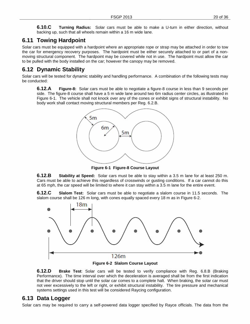
6.12.A Figure-8: Solar cars must be able to negotiate a figure-8 course in less than 9 seconds per side. The figure-8 course shall have a 5 m wide lane around two 6m radius center circles, as illustrated in Figure 6-1. The vehicle shall not knock over any of the cones or exhibit signs of structural instability. No body work shall contact moving structural members per Reg. 6.2.B.
Figure 6-1 Figure-8 Course Layout
6.12.B Stability at Speed: Solar cars must be able to stay within a 3.5 m lane for at least 250 m. Cars must be able to achieve this regardless of crosswinds or gusting conditions. If a car cannot do this at 65 mph, the car speed will be limited to where it can stay within a 3.5 m lane for the entire event.
6.12.C Slalom Test: Solar cars must be able to negotiate a slalom course in 11.5 seconds. The slalom course shall be 126 m long, with cones equally spaced every 18 m as in Figure 6-2.
Figure 6-2 Slalom Course Layout
6.12.D Brake Test: Solar cars will be tested to verify compliance with Reg. 6.8.B (Braking Performance). The time interval over which the deceleration is averaged shall be from the first indication that the driver should stop until the solar car comes to a complete halt. When braking, the solar car must not veer excessively to the left or right, or exhibit structural instability. The tire pressure and mechanical systems settings used in this test will be considered Raycing configuration.
6.13 Data Logger Solar cars may be required to carry a self-powered data logger specified by Rayce officials. The data from the
FSGP 2013 21 of 36
logger will be used to determine vehicle location and speed. The unit weighs approximately 1 kg and has an antenna of approximately 50 mm
2 that requires exposure to the sky (can be through a transparent medium).
Additional details will be provided by FSGP Headquarters.
7. Raycing
7.1 Briefings A Briefing will be held each day. Special meeting may be called in cases of emergency. Attendance at this meeting by a team representative is required. Attendance by Solar Car Driver(s) may be also required; this will be communicated to the team in advance of the briefing. Briefing notes and other daily updates will be available at headquarters. All official statements, rule interpretations, and special instructions will be contained in these postings.
7.2 Solar Car Configuration Solar cars must rayce in the same configuration as approved during Scrutineering.
7.3 Team Uniforms On all event days from 7:00 am to 8:00 pm, team members shall wear uniforms representing their Institution(s). The uniforms are required to have the Institution name, car number, and FSGP logo. If team sponsors are displayed, the event sponsor(s) must also appear in a similar manner on the team uniform. Artwork for the FSGP logo and for the event sponsor(s) may be obtained from FSGP Headquarters.
7.3.A Solar Car Drivers Attire: Solar Car Drivers, while driving, are exempted from the above requirement. Clothing worn by Solar Car Drivers must provide suitable cover and be non-offensive.
7.4 Support Vehicles All vehicles and trailers associated with a team other than the solar car itself are support vehicles. All vehicles must meet US/Canada Federal Motor Vehicle Safety Standards. All support vehicles will not be allowed on the track without prior consent by track officials.
7.4.A Safety Vehicles: Designated safety vehicles will be driven by a Rayce Official. If a track safety vehicle is needed, it will attempt to stay in the slow lane of the track. The same rules that apply to passing solar cars also apply to passing the safety vehicle. Teams may pass a static safety vehicle during an active yellow as well as any solar car not moving given the conditions are safe to pass.
7.5 Radios / Communication The team must be in two-way radio communication with the solar car driver at all times. Communications should be maintained between the solar car, the pit area, and the timing area at all times.
7.5.A Driver Communications: All communications by the solar car driver must be verbal and hands-free at all times. Hands-free operation for the solar car driver is defined as operation where the driver can activate the radio without removing his/her hands from the steering wheel.
7.5.B Cell Phone Use: Cell phones are permitted within the solar car. Any use of a cell phone in the car will need to be on a hands-free basis. Any cell phone must be fixed in position (i.e. not loose within the driver compartment).
7.6 Drivers
7.6.A Drivers: Only one person, the authorized driver, may ride in the solar car at any time. Drivers must be registered and have appropriate ballast per Reg. Error! Reference source not found..
7.6.B Driver Helmets: Drivers must wear a helmet while operating the solar car. The helmet must meet or exceed the Snell95, DOT, or ISO motorcycle standards and will be inspected during scrutineering.
7.6.C Driver Shoes: Drivers must wear closed-toe shoes in the solar car (inspector’s discretion).
7.6.D Driver Ballast: Drivers and their corresponding ballast will be identified with unique identification tags. The tags on the ballast carried by the solar car must match the tags on the solar car
FSGP 2013 22 of 36
driver at all times.
7.6.E Driving Time: Each individual driver may not drive more than a total of six hours in a given Rayce Day.
7.6.F Water/Fluids: Each driver must have sufficient quantities of water/fluids in the cockpit area to stay properly hydrated. A minimum of one liter for each driver must be provided.
7.7 Timing Timing and distance determinations for the Event will be the responsibility of Timing Officials. Headquarters will recognize no other timing or distance information. An Official Lap Count will be calculated for each entry based on actual Rayce Laps that are completed during normal raycing hours. The summation of these Laps will yield an Official Total Lap Count for the entry. Overall placing will be determined based on the highest Official Total Lap Count.
7.7.A Timers: Each team must provide a team member to serve as a timer. This team member must be in radio contact with both the solar car driver and the pit crew. The timer will be paired with a timer from another team, and the two will work together to ensure that every lap is properly recorded. Timing Officials will review all timing data for consistency and accuracy.
7.7.B Official Time: A master clock providing the "Official Time" will be located near the starting line and timing area. A solar car must cross over the start line to begin and end an official lap. All timers must record lap start/finish times based on the official time displayed.
7.7.C Track Hours: The track will be open for raycing from 9:00 am – 5:00 pm local time each of the three days. Solar cars must complete their final lap of the day prior to 5:00 pm for it to count as an official lap.
7.8 Starts Teams are released from the Start Line in a group start. The movement of all vehicles in the Start Line area will be under the control of the Start Line Officials.
7.8.A Starting Order: For the first day of the Rayce, the starting order will be determined based on performance scrutineering. On subsequent days the start order will be determined based on the total number of official laps completed thus far in the rayce.
7.8.B Start Line: Solar cars will be released simultaneously from the starting line at the beginning of each Rayce day. Teams must report to their starting position 15 minutes prior to the beginning of the start time. Control of solar cars in the start-line area is under the direction of the Start-Line Officials. Teams not ready or who are returning to the track from the cold pit area must wait for a track official to clear them for the starting line and be sequenced into traffic.
7.8.C Delayed Start: The start of the Rayce, may be delayed if inclement weather or other hazardous conditions appear likely to pose a threat to the solar cars or their drivers. If the start of the Rayce is delayed, then the assigned start time for that day will be adjusted accordingly.
7.9 Charging/Impound
7.9.A Charging: All solar cars may begin the Rayce with a fully charged battery pack. Once the Rayce begins, charging may only occur using the solar car’s array in designated charging areas.
7.9.B Impound: All registered and sealed batteries must be removed from the solar car and kept overnight in battery boxes/containers that will be secured by Headquarters. Batteries must be impounded by 8:00 PM each evening and will be released from impound at 7:00 am the following morning. Failure to impound batteries will result in a loss of all official laps completed to that point.
7.10 Driving Procedures All solar cars will proceed around the course in the prescribed direction at all times. Passing and lane information will be presented at the pre-rayce team meeting.
7.10.A Speed Limit: No solar car shall exceed the maximum speed of 104.6 km/h (65 mph), unless restricted by the Officials per Reg. Error! Reference source not found. anywhere on the track. All teams entering the pit area must slow down. A walking pace must be observed at all times in the cold pit
FSGP 2013 23 of 36
area. While in the cold pit area a team member shall walk directly in front of the solar car to ensure that the path is clear and to warn others in the area that a car is moving.
7.11 Drafting Drafting by a solar car is prohibited. A solar car will be considered to be drafting if it continuously follows behind another vehicle at less than a 3 second interval. The only exception to this is in congested traffic at speeds of 40 km/h (25 mph) or less.
7.12 Pushing Except for the following situations, solar cars may not be pushed or pulled from the time they are moved into their starting position for the Daily Start until they reach the finish line except in the cold pit areas. In no case shall regenerative braking be engaged while pushing or pulling the solar car.
7.12.A Emergency: In an emergency or breakdown situation, the solar car must be removed from the track as quickly as is prudent. In this circumstance, the car may be pushed or lifted off the track. Upon resuming Raycing, the solar car may then be pushed or lifted back onto the track to the same location where it left the track.
7.13 Breakdowns Any solar car that stops on the track because of mechanical problems, lack of power, or an accident must be moved off the track as soon as possible and prior to any repairs being performed. All teams must carry a tow strap in their solar car at all times. This tow strap will be used to facilitate a tow to the pit area by the safety vehicle, if required. No team support vehicles will be permitted on the track at any time. Team members may not run across the track to their solar car unless permission is granted by a track official. All team members attending to a broken down car on the track must be wearing a safety vest. At the discretion of the inspectors, any car having a breakdown may be required to be re-inspected for safety and rules compliance
7.13.A Accident and Re-Inspections: All accidents involving solar cars must be reported immediately to Headquarters. In the case of an accident involving personal injury, notification of the appropriate emergency medical services and public safety officials shall take priority. If a solar car is involved in an accident it must:
7.13.A.1 Stop and be visually inspected by team members.
7.13.A.2 Be re-inspected by an Inspector. The Inspector may require repairs prior to resuming the Rayce
8. Penalties Any team failing to comply with these Regulations during Scrutineering or the Rayce will be penalized. Penalties range from official warnings to disqualification from the Event. It is the responsibility of the Chief Inspector, with input from the other Inspectors and the track personal, to determine whether an infraction occurred, the severity of the incident, and the appropriate penalty. All time penalties will be submitted by the Chief Inspector to Rayce Headquarters for subsequent posting. Disqualification of a team from the Event requires concurrence of the Director. Penalties will generally be applied to total number of official laps.
8.1 Penalty Times All penalty times listed are suggested minimums. If inspectors believe the teams are deliberately violating traffic or driving regulations for strategic advantage, they may impose more severe penalties.
8.1.A Scrutineering Issues: Scrutineering issues may result in a pre-loss of laps as determined by the inspectors prior to the beginning of the FSGP. Examples of scrutineering issues include but are not limited to: car size exceeds limits and more than one ballast box. Typically these issues are the result of receiving a blue status in any inspection area. Issues within the dynamics area may also result in a reduced speed limit for the solar car on the track.
8.2 Posting of Penalties Penalties will be publicly posted by 8:30 pm each evening. On the last day of Raycing, time penalties will be posted no later than 30 minutes after the finish of the Rayce.
FSGP 2013 24 of 36
8.3 Protests Any team desiring to file a protest must do so by submitting an official protest (signed by the team leader) to Rayce Headquarters. Protests may be filed for any reason, including disputing a penalty levied against any team, correcting timing errors, or protesting the actions of another team. A “filing fee” of 5 laps will be assessed against the team’s Official Lap Count for the day on which the protest is filed. The Jury will hear all protests.
8.3.A Opportunity to Be Heard: Protests will normally be heard by the jury at the earliest possible jury sitting. It may be necessary in some instances for the jury to postpone the hearing on a protest.
8.4 Time Limit Except for the last day, all protests must be filed by 8:00am the following day the penalty is posted. On the last day of Raycing, protests for any purpose must be filed within 60 minutes after the finish of the Rayce.
8.5 Protest Judgments The decision of the Jury is final and no further appeals are allowed. The Jury will notify Rayce Headquarters of their decision, and Rayce Headquarters will then inform the affected teams. The Jury may refund some or the entire filing fee, which will be credited to the day the filing fee was assessed.
8.6 Conduct Penalties, including disqualification from the Event, may be imposed for improper conduct or the use of alcohol or illegal substances. Improper conduct may include, but is not limited to, improper language, unsportsmanlike conduct, unsafe behavior, or cheating. Teams are responsible for the conduct of all persons associated with the team, whether or not they are officially registered.
8.7 Time Penalties
8.7.A Speeding: Any solar car found to be speeding shall be penalized. Speeding penalties may be assessed based on the following factors: (1) velocity over speed limit, (2) length of time of speeding infraction. Penalties will be assed with a loss of a lap multiplied by the infraction count for that specific instance. Speeding infractions including a rate of speed of 112.6 km/h (70 mph) or greater will result in a 1 hour penalty associated with the team’s fastest lap speeds.
8.7.B Traffic Violations: Any solar car committing a traffic violation may be penalized, up to disqualification. Any solar car driver who commits three traffic violations (including speeding) over the course of the Rayce may be individually disqualified from the Event.
8.7.C Failure to Allow Other Solar Cars to Pass: Any team failing to properly facilitate passing of other solar cars may be penalized 2 laps.
8.7.D Drafting: A 2 lap penalty may be assessed for any time a solar car drafts behind another vehicle.
8.7.E Pushing: a loss of the current lap will result each time a team pushes or pulls their solar car in order to advance along the track. (Except in an emergency as in Reg. 7.12)
8.7.F Improper Ballast: A 30 min penalty associated with the team’s fastest lap speeds may be assessed each time a team operates their solar car with ballast that does not match the solar car driver.
8.7.G Unauthorized Drivers: Any solar car that is rayced with an unauthorized driver will forfeit all laps driven with said driver
8.7.H Non-Solar Charging of Batteries: After the start of the Rayce until the official finish, teams will be disqualified from the Event for charging their solar car’s storage batteries from any source other than those allowed by Reg. 5.1, without specific written instruction from Rayce Officials. Such charging of a solar car storage battery will constitute replacement and is subject to Reg. 8.7.J.
8.7.I Disturbing Official Battery Seals: Solar car batteries will be marked with an official seal. Disturbing these seals in a manner that prevents proper identification by Inspectors may be penalized as though all of the battery modules affected had been replaced as in Reg. 8.7.J.
8.7.J Replacement of Batteries: Decisions to exchange (or externally recharge – see Reg. 8.7.H) all or part of a battery must be communicated formally to an Inspector. The penalty will be computed as
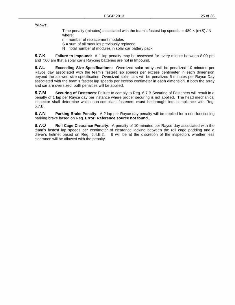
FSGP 2013 25 of 36
follows:
Time penalty (minutes) associated with the team’s fastest lap speeds = 480 × (n+S) / N where: n = number of replacement modules S = sum of all modules previously replaced N = total number of modules in solar car battery pack
8.7.K Failure to Impound: A 1 lap penalty may be assessed for every minute between 8:00 pm and 7:00 am that a solar car’s Raycing batteries are not in Impound.
8.7.L Exceeding Size Specifications: Oversized solar arrays will be penalized 10 minutes per Rayce day associated with the team’s fastest lap speeds per excess centimeter in each dimension beyond the allowed size specification. Oversized solar cars will be penalized 5 minutes per Rayce Day associated with the team’s fastest lap speeds per excess centimeter in each dimension. If both the array and car are oversized, both penalties will be applied.
8.7.M Securing of Fasteners: Failure to comply to Reg. 6.7.B Securing of Fasteners will result in a penalty of 1 lap per Rayce day per instance where proper securing is not applied. The head mechanical inspector shall determine which non-compliant fasteners must be brought into compliance with Reg. 6.7.B.
8.7.N Parking Brake Penalty: A 2 lap per Rayce day penalty will be applied for a non-functioning parking brake based on Reg. Error! Reference source not found..
8.7.O Roll Cage Clearance Penalty: A penalty of 10 minutes per Rayce day associated with the team’s fastest lap speeds per centimeter of clearance lacking between the roll cage padding and a driver’s helmet based on Reg. 6.4.E.2. It will be at the discretion of the inspectors whether less clearance will be allowed with the penalty.
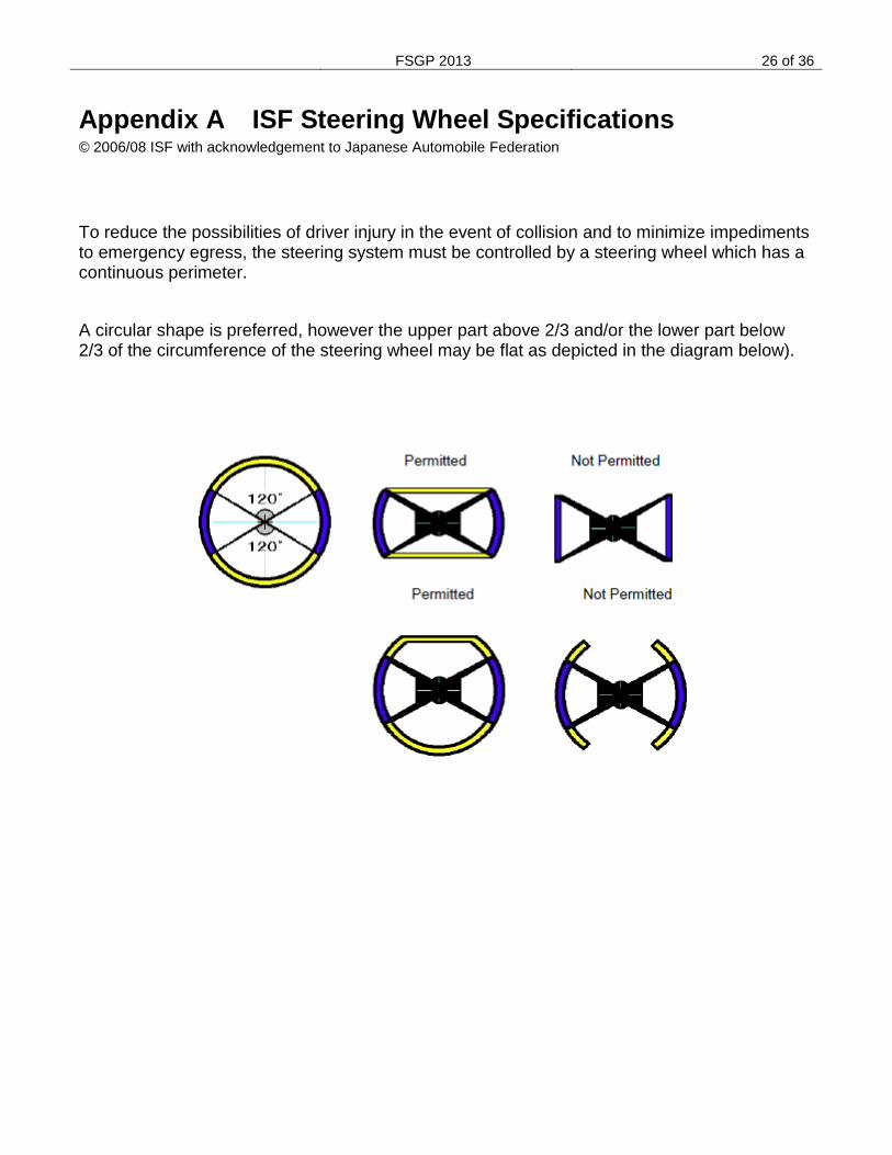
FSGP 2013 26 of 36
Appendix A ISF Steering Wheel Specifications © 2006/08 ISF with acknowledgement to Japanese Automobile Federation
To reduce the possibilities of driver injury in the event of collision and to minimize impediments to emergency egress, the steering system must be controlled by a steering wheel which has a continuous perimeter.
A circular shape is preferred, however the upper part above 2/3 and/or the lower part below 2/3 of the circumference of the steering wheel may be flat as depicted in the diagram below).
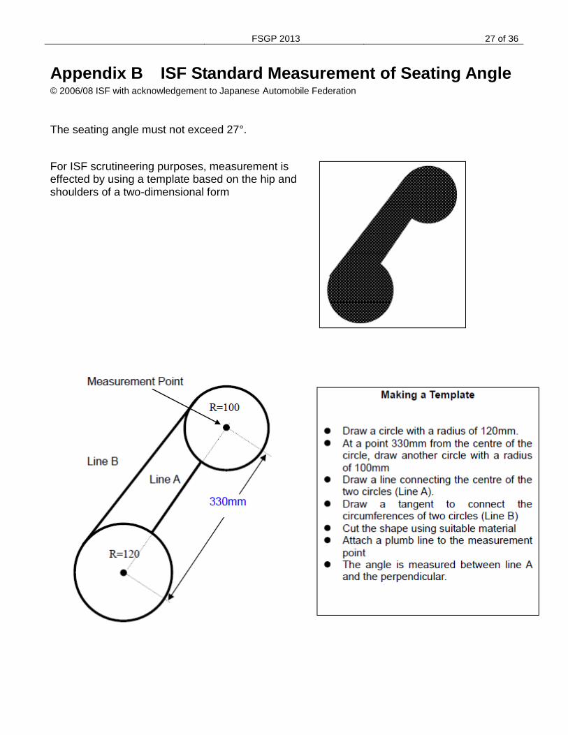
FSGP 2013 27 of 36
Appendix B ISF Standard Measurement of Seating Angle © 2006/08 ISF with acknowledgement to Japanese Automobile Federation
The seating angle must not exceed 27°.
For ISF scrutineering purposes, measurement is effected by using a template based on the hip and shoulders of a two-dimensional form
FSGP 2013 28 of 36
Appendix C Reference Standard for Lighting Reference Regulation 5.9
The reference standard lights are:
TruFLEX
20 LED (Length 3.35 in)
Item TF20 from Custom Dynamics
Red lights are Red LED with Red lens
Amber lights are Amber LED with Amber lens
(www.CustomDynamics.com 1-800-382-1388)
The reference standard lights will be used in the following manner:
Lights shall be powered by a 12 volt power source
Light shall be centered on a flat surface with a matte white finish of 11” x 8.5”.
Separate light boards shall be used for each color type as the standard reference.
Reference standard light boards shall be set aside of car to compare during inspections.
FSGP 2013 29 of 36
Appendix D Mechanical Report Instructions
It is the intent of the FSGP Event to maintain the safest entries possible while encouraging a wide variety of designs and materials for solar-powered vehicles. The purpose of the structural report is to require each team to document, by calculation or testing, the structural integrity of their vehicle and the protection provided to their drivers. Note that each team is responsible for the safety of its members, and any minimum criteria specified by FSGP should not be construed as design specifications for the construction of a “safe” solar vehicle. The structural report shall be presented in the format described in this document. Reports that do not meet this format will not be read and could jeopardize a team‟s chances for competing in the event. The report should be written to be as concise as possible and should only present information relevant to the requirements of the report. The report is limited to a total of 50 pages, including appendices. Section 1: Introduction A brief summary of your project and the overall design of your vehicle. This should include overall dimensions, component location and layout, and driver position. Teams should describe the vehicle both in its normal racing configuration, and in its stationary charging configuration. Section 2: Mechanical Systems Analysis The mechanical systems analysis section must include the following six sub-sections:
Front suspension
Rear suspension
Brakes
Steering
Wheels & Tires
Battery Enclosure Each sub-section must contain all of the following information:
Material Specifications: Describe the materials utilized, their important dimensions (e.g., tubing diameter and thickness), and material properties (in the “as welded” or “as fabricated” condition).
Loading Conditions: Describe the specific loading conditions used in the analysis of the component. Teams should consider road and traffic conditions when determining loading criteria and potential failure modes. For suspension and steering systems, analysis needs to include at least a 1G turn, a 2G bump, and 1G braking case. Loads should be provided in dimensional units. Include any relevant assumptions used in the analysis.
Drawings: Include component drawings or photographs and mechanical system assembly drawings or photographs. All drawings must be identified by number and must include a description. In the case of purchased or procured components, include the manufacturer and part numbers.
System Analysis: Mechanical components and systems must be analyzed to show that they will not fail due to fatigue and possess a reasonable factor of safety for strength and stress. Provide a summary of both the analytical methods used and the analytical results for each mechanical component or system. Analyzes may be in the form of either calculations, computer modeling (such as finite-element analysis), or empirical testing of the actual vehicle or its components. If testing is not completed at the time the report is submitted, detailed plans of the
FSGP 2013 30 of 36
scheduled testing must be included in the report. The results from the described tests must be submitted once they have been completed. All teams must include the expected static weight on each tire.
Teams must show how they intend to build and secure battery enclosures to meet the requirements of Reg. 5.5. Include a description of how the enclosure will be ventilated and how the cells will be secured within the battery enclosure. Provide a discussion of your findings and how the results impacted your design.
Section 3: Vehicle Impact Analysis The vehicle impact analysis section must include the following topics:
Specifications: The report must describe the vehicle frame and construction techniques (aluminum space frame, composite monocoque, etc.), including the materials utilized, their important dimensions (e.g., tubing diameters and thicknesses, number and types of plies in composite constructions), and their properties (in the "as welded" or "as fabricated" condition). The report must also list the specific impact criteria that are assumed for each case, as well as sample calculations and computer output as applicable. Other relevant assumptions used in the analysis should be listed.
Drawings: The report must include structural drawings of the vehicle from five viewpoints: top, front, side, rear, and isometric. These drawings must illustrate the following:
o Driver location and orientation
o All members considered "structural"
o Locations of ballast and batteries
o Locations of chassis hard points (points of attachment).
o Calculated center of mass The report must contain structural drawings of the driver's compartment from three viewpoints: top, front, and side. These drawings must illustrate the following:
o Driver location
o "Crush" space between the driver and the outer perimeter of the vehicle
o Roll cage design and location
o Location of structural members
o Driver's harness attachment points The report must contain an isometric drawing of the body and solar array. All drawings must be identified by number and must include a description.
Analysis: Analyzes may be in the form of computer modeling (such as a finite-element analysis) or empirical testing of the actual vehicle or its components. The report must document the performance of the vehicle regarding front, rear, side, and rollover impact, using appropriate forms of analysis. Front, rear, and side impact with another vehicle assumes a bumper height of 100 mm and elevation off the ground of 350 mm as shown in Figure 1. Rollover analysis must address loads at a minimum vertical and two increments between horizontal and vertical.
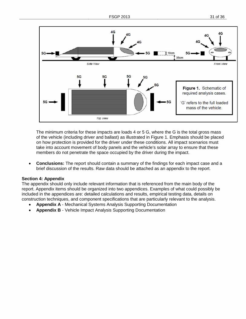
FSGP 2013 31 of 36
The minimum criteria for these impacts are loads 4 or 5 G, where the G is the total gross mass of the vehicle (including driver and ballast) as illustrated in Figure 1. Emphasis should be placed on how protection is provided for the driver under these conditions. All impact scenarios must take into account movement of body panels and the vehicle's solar array to ensure that these members do not penetrate the space occupied by the driver during the impact.
Conclusions: The report should contain a summary of the findings for each impact case and a
brief discussion of the results. Raw data should be attached as an appendix to the report. Section 4: Appendix The appendix should only include relevant information that is referenced from the main body of the report. Appendix items should be organized into two appendices. Examples of what could possibly be included in the appendices are: detailed calculations and results, empirical testing data, details on construction techniques, and component specifications that are particularly relevant to the analysis.
Appendix A - Mechanical Systems Analysis Supporting Documentation
Appendix B - Vehicle Impact Analysis Supporting Documentation
FSGP 2013 32 of 36
Appendix E Electrical System Report Instructions
It is the intent of the FSGP Event to maintain the safest entries possible while encouraging a wide variety of designs and materials for solar-powered vehicles. The purpose of the electrical system report is to require each team to document, the design of the electrical system of the solar car. The report shall be presented in the format described in this document. Reports that do not meet this format will not be read and could jeopardize a team‟s chances for competing in the event. The report should be written to be as concise as possible and should only present information relevant to the requirements of the report.
The following sections shall be provided: 1. Introductory paragraph telling FSGP Staff about your vehicle: new design, carryover
from prior event, etc… 2. If your vehicle design is not to the state of describing these functions, submit your
“PLANS” and describe that aspect in the Introductory Statement. 3. High Voltage Schematic – Minimum of ALL propulsion wiring 4. Descriptive understanding of the ALL high voltage functions during a Battery Event –
Paragraph and possibly schematics 5. Descriptive understanding of Battery Fan function – schematic may be used here as
well 6. Who to contact if an issue is found in this document: 7. Team Electrical Contact 8. And Team Battery Contact
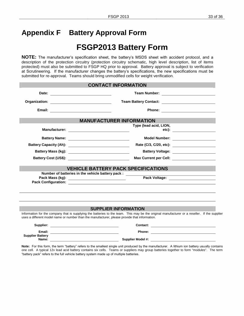
FSGP 2013 33 of 36
Appendix F Battery Approval Form
FSGP2013 Battery Form
NOTE: The manufacturer’s specification sheet, the battery’s MSDS sheet with accident protocol, and a
description of the protection circuitry (protection circuitry schematic, high level description, list of items protected) must also be submitted to FSGP HQ prior to approval. Battery approval is subject to verification at Scrutineering. If the manufacturer changes the battery’s specifications, the new specifications must be submitted for re-approval. Teams should bring unmodified cells for weight verification.
CONTACT INFORMATION
Date: Team Number:
Organization: Team Battery Contact:
Email: Phone:
MANUFACTURER INFORMATION
Manufacturer: Type (lead acid, LION,
etc):
Battery Name: Model Number: Battery Capacity (Ah): Rate (C/3, C/20, etc):
Battery Mass (kg): Battery Voltage:
Battery Cost (US$): Max Current per Cell:
VEHICLE BATTERY PACK SPECIFICATIONS Number of batteries in the vehicle battery pack :
Pack Mass (kg): Pack Voltage:
Pack Configuration:
SUPPLIER INFORMATION
Information for the company that is supplying the batteries to the team. This may be the original manufacturer or a reseller. If the supplier uses a different model name or number than the manufacturer, please provide that information.
Supplier: Contact:
Email: Phone: Supplier Battery
Name: Supplier Model #:
Note: For this form, the term “battery” refers to the smallest single unit produced by the manufacturer. A lithium ion battery usually contains one cell. A typical 12v lead acid battery contains six cells. Teams or suppliers may group batteries together to form "modules". The term
“battery pack” refers to the full vehicle battery system made up of multiple batteries.
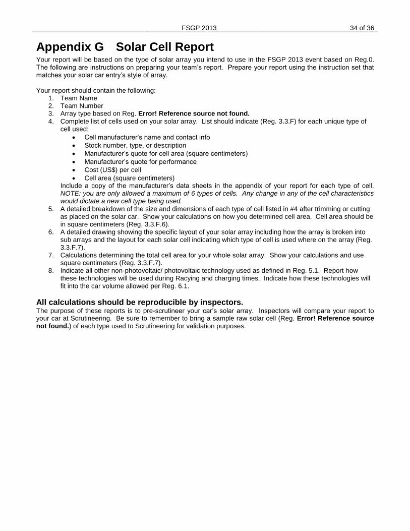
FSGP 2013 34 of 36
Appendix G Solar Cell Report Your report will be based on the type of solar array you intend to use in the FSGP 2013 event based on Reg.0. The following are instructions on preparing your team’s report. Prepare your report using the instruction set that matches your solar car entry’s style of array. Your report should contain the following:
1. Team Name 2. Team Number 3. Array type based on Reg. Error! Reference source not found. 4. Complete list of cells used on your solar array. List should indicate (Reg. 3.3.F) for each unique type of
cell used:
Cell manufacturer’s name and contact info
Stock number, type, or description
Manufacturer’s quote for cell area (square centimeters)
Manufacturer’s quote for performance
Cost (US$) per cell
Cell area (square centimeters) Include a copy of the manufacturer’s data sheets in the appendix of your report for each type of cell. NOTE: you are only allowed a maximum of 6 types of cells. Any change in any of the cell characteristics would dictate a new cell type being used.
5. A detailed breakdown of the size and dimensions of each type of cell listed in #4 after trimming or cutting as placed on the solar car. Show your calculations on how you determined cell area. Cell area should be in square centimeters (Reg. 3.3.F.6).
6. A detailed drawing showing the specific layout of your solar array including how the array is broken into sub arrays and the layout for each solar cell indicating which type of cell is used where on the array (Reg. 3.3.F.7).
7. Calculations determining the total cell area for your whole solar array. Show your calculations and use square centimeters (Reg. 3.3.F.7).
8. Indicate all other non-photovoltaic/ photovoltaic technology used as defined in Reg. 5.1. Report how these technologies will be used during Racying and charging times. Indicate how these technologies will fit into the car volume allowed per Reg. 6.1.
All calculations should be reproducible by inspectors. The purpose of these reports is to pre-scrutineer your car’s solar array. Inspectors will compare your report to your car at Scrutineering. Be sure to remember to bring a sample raw solar cell (Reg. Error! Reference source not found.) of each type used to Scrutineering for validation purposes.
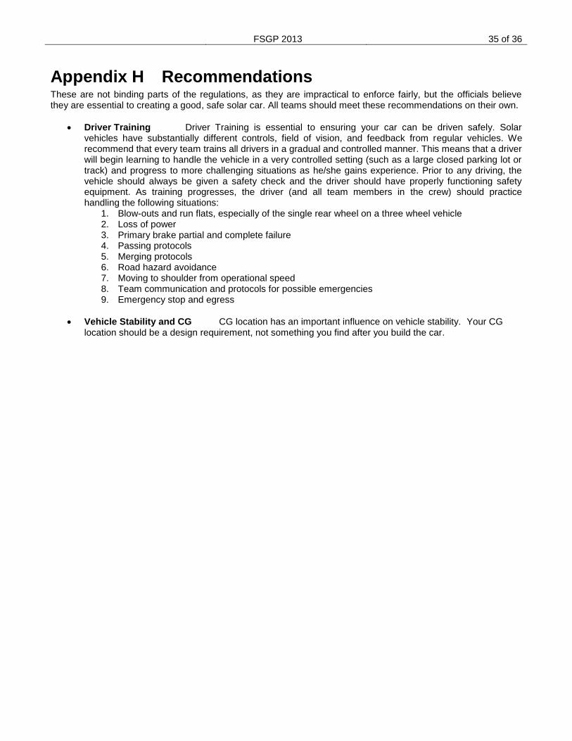
FSGP 2013 35 of 36
Appendix H Recommendations These are not binding parts of the regulations, as they are impractical to enforce fairly, but the officials believe they are essential to creating a good, safe solar car. All teams should meet these recommendations on their own.
Driver Training Driver Training is essential to ensuring your car can be driven safely. Solar vehicles have substantially different controls, field of vision, and feedback from regular vehicles. We recommend that every team trains all drivers in a gradual and controlled manner. This means that a driver will begin learning to handle the vehicle in a very controlled setting (such as a large closed parking lot or track) and progress to more challenging situations as he/she gains experience. Prior to any driving, the vehicle should always be given a safety check and the driver should have properly functioning safety equipment. As training progresses, the driver (and all team members in the crew) should practice handling the following situations:
1. Blow-outs and run flats, especially of the single rear wheel on a three wheel vehicle 2. Loss of power 3. Primary brake partial and complete failure 4. Passing protocols 5. Merging protocols 6. Road hazard avoidance 7. Moving to shoulder from operational speed 8. Team communication and protocols for possible emergencies 9. Emergency stop and egress
Vehicle Stability and CG CG location has an important influence on vehicle stability. Your CG location should be a design requirement, not something you find after you build the car.
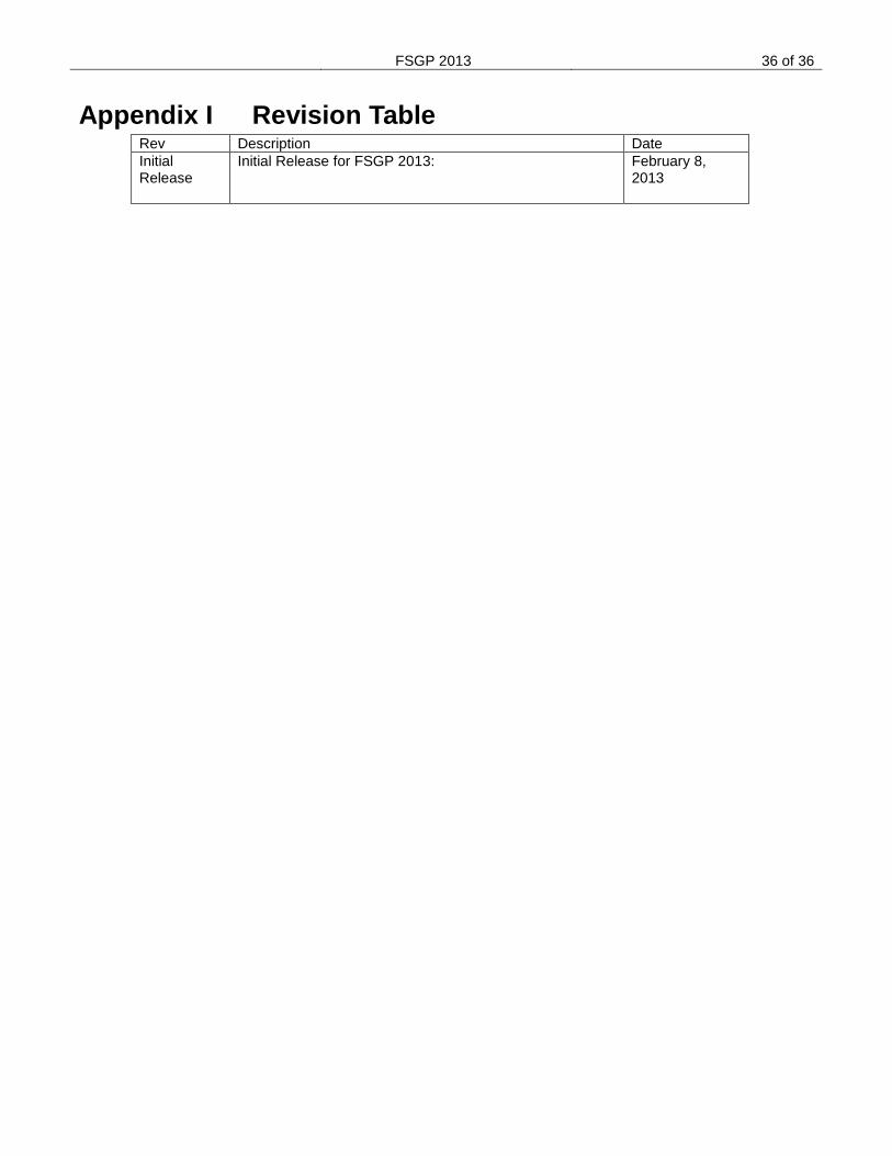
FSGP 2013 36 of 36
Appendix I Revision Table Rev Description Date
Initial Release
Initial Release for FSGP 2013:
February 8, 2013


