FS13560 Aluminium Attic Ladder - Bailey...
22
FS13560 Aluminium Attic Ladder Installation Instructions Table of Contents Page Parts and Tools 2 Before you begin 3 Step 1 Preparing Existing Attic Ladder Opening for Installation 4-5 Step 2 Placing Ladder into Prepared Opening 6-7 Step 3 Permanent Mounting of Ladder 8 Step 4 Setting Ladder Height 9 Step 5 Attaching the Feet 10-11 Appendix 12-20 Replacement Parts 21 FAILURE TO COMPLY WITH ALL INSTRUCTIONS MAY RESULT IN SERIOUS INJURY
Transcript of FS13560 Aluminium Attic Ladder - Bailey...

FS13560 Aluminium Attic Ladder
Installation Instructions
Table of Contents PageParts and Tools 2Before you begin 3
Step 1 Preparing Existing Attic Ladder Openingfor Installation 4-5
Step 2 Placing Ladder into Prepared Opening 6-7Step 3 Permanent Mounting of Ladder 8Step 4 Setting Ladder Height 9Step 5 Attaching the Feet 10-11
Appendix 12-20Replacement Parts 21
FAILURE TO COMPLY WITH ALL INSTRUCTIONS MAY RESULT IN SERIOUS INJURY

INCLUDED FASTENERS
Parts and Tools For FS13560 Aluminium Attic Ladder
2
(10) 1/4" x 20 Hex HeadLag Screws 5.08 cm Long
(2) 1/4"- 20 Hex Head Cap Screws1.91 cm Long
(2) 1/4" - 20 Lock Nut
(11) 1/4" Washers
TOOLS NEEDEDCarpenter’s SquareDrillHammerHacksawDrill Bit, 1/8"Drill Bit, 9/32"PencilStepladderTape MeasureWrench, 7/16" (2)Phillips Driver
ADDITIONAL MATERIALS NEEDED(10) #8 Deck Screws, 5.08 cm
2.5 cm x 10.1 cm Temporary Support Boards(2 pieces approximately 0.81 m long)
Shims
INCLUDED COMPONENTS(1) Left FootAssembly
(1) Right FootAssembly
(1) Pull RopeAssembly
(1) Ladder Assembly
DO NOT REMOVE NYLON TIE HOLDING THE LADDER SECTIONS TOGETHER UNTIL INSTRUCTED

3
a. To save time and prevent accidents, inspect the attic ladder for shipping damage before beginning theinstallation.
• Check wooden door panel for splits and warpage• Check all metal parts for damage such as bends and cracks• Check that all rivets are tight
If any items are missing or damaged, contact the point of purchase.
b. You must have• 2 people who are capable of lifting the 22.7 kg attic ladder into the overhead space
c. You must have:• A rough opening in the ceiling measuring 0.57 m x 1.37 m. If not, proceed to the Appendix, Section 1.1, page 12.
d. Verify clearance requirements:• See Appendix, Section 1.3, Figure 3, page 14
BEFORE YOU BEGIN:
Read instructions completely before beginning. This is necessary to ensure that you have a suitablelocation for the attic ladder and the ability to safely and properly install it.
Are you capable of installing this attic ladder?To install this attic ladder you should have sawing, squaring, and aligning skills similar to those required to install awindow or a door frame. If you do not have these skills you should hire a professional carpenter to install this unit(see the Yellow Pages under “Building Contractors, Carpenters, Home Builders, Home Improvements, orContractors-General”).
Does this attic ladder meet your needs?This attic ladder is for residential use only. Installing this attic ladder in commercial buildings and apartments mayviolate building codes that require fire-rated ceilings and prohibit storing materials in the overhead space! Check withyour local fire marshal or building department before installing the attic ladder.The capacity of the attic ladder (person plus materials being carried) is 170 kg.This attic ladder is made for the range of ceiling heights 2.34 m to 3.12 m. Do not install the attic ladder in a ceilingthat has a height outside of this range. Altering the attic ladder to accommodate other heights is unsafe.

For best results make sure the ceilingaround the opening is flat and in goodrepair and that all sides of the openingare flat, plumb and in good repair.
1. PREPARING EXISTING OPENING: (See Figure B)a. Remove any trim and hardware surrounding
the opening.
b. Inspect existing attic ladder opening to make sure it meets minimum construction requirements and is 0.57 m x 1.37 m (Figure C1)
c. If it is necessary to modify or create a new opening, please refer to Appendix,Section 1.1, page 12.
4
Step 1 PREPARING EXISTING ATTIC LADDER OPENING FOR INSTALLATION
TOOLS NEEDEDADDITIONAL MATERIALS NEEDED
StepladderHammerTape MeasurePencilCarpenter’s SquareDrillPhillips Driver
(6) #8 Deck Screws, 5.08 cm
2.54 cm x 10.16 cm Temporary Support Boards(2 pieces approximately 0.81 m long)
Figure B
Header
Figure C1Header
Header
16d Nails(6) per Header
Joists
Figure A
Header AHeader B
FinishedCeiling
FinishedCeiling1st Temporary
Support2nd Temporary
Support
At completion of Steps 1 & 2 the frame of your ladder will be installed flush with the underside ofthe finished ceiling. (See Figure A)
1.37 m
0.57 m

WARNING Support boards must be fastened securely totemporarily support the weight of the ladderwhen it is placed in the rough opening.
2. ATTACHING TEMPORARY SUPPORT BOARDS:
It is necessary to temporarily support theladder in the prepared rough opening by using2.54 cm x 10.16 cm x 0.81 m boards thatextend from edge to edge across each end ofthe rough opening. The boards form a ledgeto support the ladder before it is permanentlysecured. Care is important in positioning theboards.
a. Secure first temporary support 0.95 cm from the inside edge of Header “A”. Header “A” is the end where the hinge of the ladder will go. Make sure all (3) screws penetrate header. (See Figure D & E).
b. Measuring from the inside edge of first temporary support, secure second temporary support so that the inside edge is 1.33 m from inside edge of the first temporary support. (See Figure D)
c. Be certain both first and second temporary supports are secured firmly into respective headers. (See Figure E).
YOUR ATTIC LADDER OPENING IS NOW PREPARED FOR INSTALLATION. PROCEED TO STEP 2 - PLACING LADDER INTO PREPARED OPENING
Figure D (View from above)
Insideedge
Header A
Header B
2ndTemporarySupport Inside Edges
1.33 m
HingedEnd ofLadder
1stTemporarySupport
0.95 cm
Figure E (View from below)
Deck Screws (3) per TemporarySupport Board
Step 1 (continued)
PREPARING EXISTING ATTIC LADDER OPENING FOR INSTALLATION
WARNING Make sure that the temporary support boardsare 1.33 m apart on both sides of opening. The attic ladder is likely to fall from the ceiling if the temporary support boards are not properlyspaced.
5
Ceiling Joist 0.95 cm

WARNING DO NOT remove the nylon tie holding the laddersections together until after the ladder has beenproperly installed and secured.
2nd Temporary Support Board
WARNING Do not place any weight on the ladder untilpermanently installed in Step 3, page 8.
The person in the overhead space must remainthere until installation is completed.
1. ATTACHING PULL CORD: (See Figure F)
a. Thread small end of supplied pull rope through pre-drilled hole in door and tie to the washer. You can adjust length of pull rope after ladder is completely installed.
2. RAISING LADDER INTO ROUGH OPENING:
a. One person should be in the attic before raising the ladder.
b. Raise ladder through rough opening at an angle so the ladder clears the temporary support boards. (See Figure G)
c. Position the ladder in the rough opening so it rests securely on the temporary support boards. Slide the ladder so that the hinged end of the wood frame is resting tightly against Header “A” (See Figure H). Make certain the plywood door is not prevented from opening by the support boards. (See Figure I) If it is obstructed check the position of the support boards from Step 1.
StepladderTape MeasureHammerDrillPhillips Driver
ADDITIONALMATERIALSNEEDED
TOOLSNEEDED
INCLUDEDFASTENERS
6
Step 2 PLACING LADDER INTO PREPARED OPENING
Figure F
Tie toWasher
INCLUDEDCOMPONENTS
(1) Ladder Assembly
(1) Pull Rope
Shims
Figure G
Door
1st TemporarySupport
2nd TemporarySupport
Figure I
Header ANo GapsHinged End
Figure H
Approximately 0.32 cm Gap
(4) #8 Deck Screws, 5.08 cm
V iew from above
V iew from below
(1) 1/4"-20Washer
WARNING Be careful when using a stepladder to climb into andout of the overhead space.

3. SQUARING THE LADDER IN OPENING:
a. Centre the hinged end of the ladder on Header “A” so that there is equal space on both sides (See Figure J). Drive (2) screws, (See Figure J), to hold the frame to Header “A”. Screws to go through wood frame only. Holes in steel hinge plate are for use in Step 3.
b. Open ladder door by pulling straight down on the pull rope. Ladder sections should remain folded with nylon ties attached.
c. Shim the frame at corner locations if needed (See Figure K) so that the two diagonal dimensions are equal. The frame is square when the dimensions are equal. If dimensions cannot be made equal within 0.32 cm by shimming, the hinged end of the ladder may need to be repositioned. (See Figure K)
Failure to properly square the frame may result in ladderclosing at an angle. If this occurs, there may be contactbetween the frame and ladder, causing door not to closeproperly. Check frame for squareness by measuringacross diagonals (See Figure K). The two dimensionsshould be equal within 0.32 cm to be considered square.
d. Drive (2) screws as shown at the end opposite of the hinge to hold the shims in place. Do not drive screws through blocks. (See Figure K)
Figure J
Figure K
YOUR ATTIC LADDER HAS BEEN PROPERLY PLACED INTO THE PREPARED OPENING.PROCEED TO STEP 3 -PERMANENT MOUNTING OF LADDER.
Step 2 (continued)
PLACING LADDER INTO PREPARED OPENING
7
Header“A”
Gap sameas Right
Gap sameas Left
DeckScrew
DeckScrew
Deck Screws(through wood
only)
Deck Screws

1. SECURING LADDER IN ROUGH OPENING:
a. Pre-drill (4) 1/8" pilot holes and install (4) 1/4" x 5.08 cm hex head lag screws into Header “A” using hinge plate as template. (See Figure L) (4) 1/4" washers to be used under heads of lag screws.
b. If necessary, carefully place shims behind Mounting Plates (See inset - Figure M) Do not bow sides of ladder frame with shims. Pre-drill (2) 1/8" pilot holes and install (2) 1/4" x 5.08 cm hex head lag screws into Mounting Plates. (2) 1/4" washers to be used under heads of lag screws. (See Figure M)
c. Pre-drill (4) 1/8" pilot holes approximately as shown. Install (4) 1/4" x 5.08 cm hex head lag screws. (4) 1/4" washers to be used under heads of lag screws.
d. Make sure door closes without interference. Readjust shims if necessary
Trim portion of shims that stick out above and below frame.Shims sticking out above the frame are a tripping hazardand must be trimmed.
2. REMOVE TEMPORARY SUPPORT BOARDS
8
Step 3 PERMANENT MOUNTING OF LADDER
Figure L
ADDITIONALMATERIALSNEEDED
TOOLS NEEDEDINCLUDED FASTENERS
StepladderDrill1/8" Drill BitWrench, 7/16" (1)Hammer
(10) 1/4" x 20 HexHead Lag Screws,5.08 cm Long
(10) 1/4" Washers
YOUR ATTIC LADDER HAS BEEN PERMANENTLY MOUNTED INTO OPENING.PROCEED TO STEP 4 -SETTING LADDER HEIGHT.
LagScrewand
Washer
Lag Screwsand Washers
Header A
Figure M
Shims
LagScrews
Mounting Plate
Shim (ifnecessary)

Cut under step (only for 2.36 m to2.34 m dimensions from chart)
9
Step 4 SETTING LADDER HEIGHT
The lower section of the ladder may requiretrimming and adjusting feet to proper height.
1. TAKING YOUR MEASUREMENT: (See Figure N)a. With the unextended ladder in the fully
open position, measure height “Y” from bottom of the wood frame of the attic ladder to the floor. Refer to Table 1 before proceeding to the next step.
2. TRIMMING LOWER SECTION:
a. Remove the nylon tie holding the ladder sections together.
b. Fold the lower section of the unit under the middle section (See Figure O).
c. Measure the required cut off distance “X”, defined in Table 1, from the bottom of the
lower section and mark a straight line perpendicular to rail, using a pencil and carpenter’s square. (See Figure O)
d. With ladder properly supported, use a hacksaw to cut off excess lower section at
line marked in step c.e. Unfold lower section of the unit to the
open position.
Figure O
TOOLS NEEDED
Figure N
Table 1
Cut according tomeasurements
X
YOUR ATTIC LADDER HEIGHT HAS BEEN PROPERLY SET.PROCEED TO STEP 5 - ATTACHING THE FEET
Y
Support arms
WARNING The attic ladder must be adjusted to match theproper height where it is installed. Failure to doso may result in damage to the ladder or injuryto the user.
HacksawTape Measure
PencilCarpenter’s Square
Figure P
Distance “Y” “X”If your But more Thenheight than or cut off
is less than: equal to: is:
312.4 cm 0 cm
312.4 cm 309.9 cm 2.5 cm
309.9 cm 307.3 cm 5.1 cm
307.3 cm 304.8 cm 7.6 cm
304.8 cm 302.3 cm 10.8 cm
302.3 cm 299.7 cm 13.3 cm
299.7 cm 297.2 cm 15.9 cm
297.2 cm 294.6 cm 19.1 cm
294.6 cm 292.1 cm 21.6 cm
292.1 cm 289.6 cm 29.2 cm
289.6 cm 287.0 cm 29.2 cm
287.0 cm 284.5 cm 30.5 cm
284.5 cm 281.9 cm 33.0 cm
281.9 cm 279.4 cm 35.6 cm
279.4 cm 276.9 cm 38.7 cm
276.9 cm 274.3 cm 41.3 cm
Distance “Y” “X”If your But more Thenheight than or cut off
is less than: equal to: is:
274.3 cm 271.8 cm 43.8 cm
271.8 cm 269.2 cm 47.0 cm
269.2 cm 266.7 cm 49.5 cm
266.7 cm 264.2 cm 52.1 cm
264.2 cm 261.6 cm 59.7 cm
261.6 cm 259.1 cm 59.7 cm
259.1 cm 256.5 cm 61.0 cm
256.5 cm 254.0 cm 64.1 cm
254.0 cm 251.5 cm 66.7 cm
251.5 cm 248.9 cm 69.2 cm
248.9 cm 246.4 cm 72.4 cm
246.4 cm 243.8 cm 74.9 cm
243.8 cm 241.3 cm 77.5 cm
241.3 cm 238.8 cm 81.3 cm
238.8 cm 236.2 cm 83.2 cm
236.2 cm 233.7 cm See Figure P
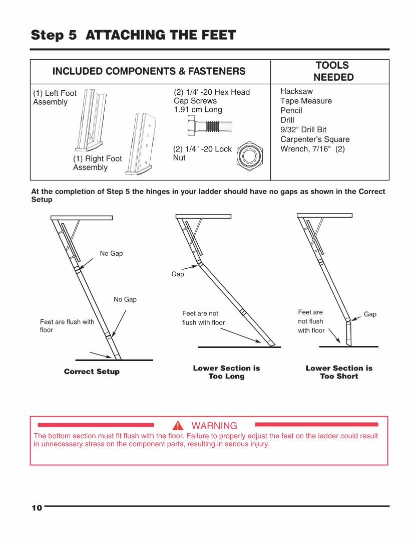
(2) 1/4' -20 Hex HeadCap Screws1.91 cm Long
No Gap
No Gap
Feet are flush withfloor
Correct Setup
Gap
Feet are notflush with floor
GapFeet arenot flushwith floor
Lower Section isToo Long
10
Step 5 ATTACHING THE FEET
TOOLSNEEDED
INCLUDED COMPONENTS & FASTENERS
HacksawTape MeasurePencilDrill9/32" Drill BitCarpenter’s SquareWrench, 7/16" (2)
(1) Right FootAssembly
(1) Left FootAssembly
WARNING The bottom section must fit flush with the floor. Failure to properly adjust the feet on the ladder could resultin unnecessary stress on the component parts, resulting in serious injury.
Lower Section isToo Short
At the completion of Step 5 the hinges in your ladder should have no gaps as shown in the CorrectSetup
(2) 1/4" -20 LockNut

Step 5 (continued)
ATTACHING THE FEET
11
1. PROPER FOOT LOCATION:
a. Be sure ladder sections are fully extended and support arms are fully open. Apply pressure as shown to make sure ladder is fully extended. (See Figure Q)
b. Place foot over side rail and slide foot downward until the rubber foot pad rests firmly on the floor. Apply light pressure as shown. (See Figure R)
c. Mark location to drill hole through side rail of lower section using one of the pre-drilled holes in the adjustable foot as a template. Remove foot and check position of hole before drilling. Drill 9/32" hole through the rail. (See Figure S)
d. Install adjustable foot and tighten using 1/4" hex head cap screw and lock nut provided. (See Figure T)
e. Repeat steps a through d for other side of ladder.
Figure R
Figure T
Figure S
Pencil
Foot reston floor
Pre-drilledhole
Hex HeadCap Screw
Lock Nut
Figure Q
Apply downwardpressure here
No Gap
Support Arms
Side rail
Side rail
Side rail
Side rail
No Gap
Floor
Direction toapply lightpressure
CONGRATULATIONS - YOUR LADDER IS NOWCOMPLETELY INSTALLED AND READY FOR USE.
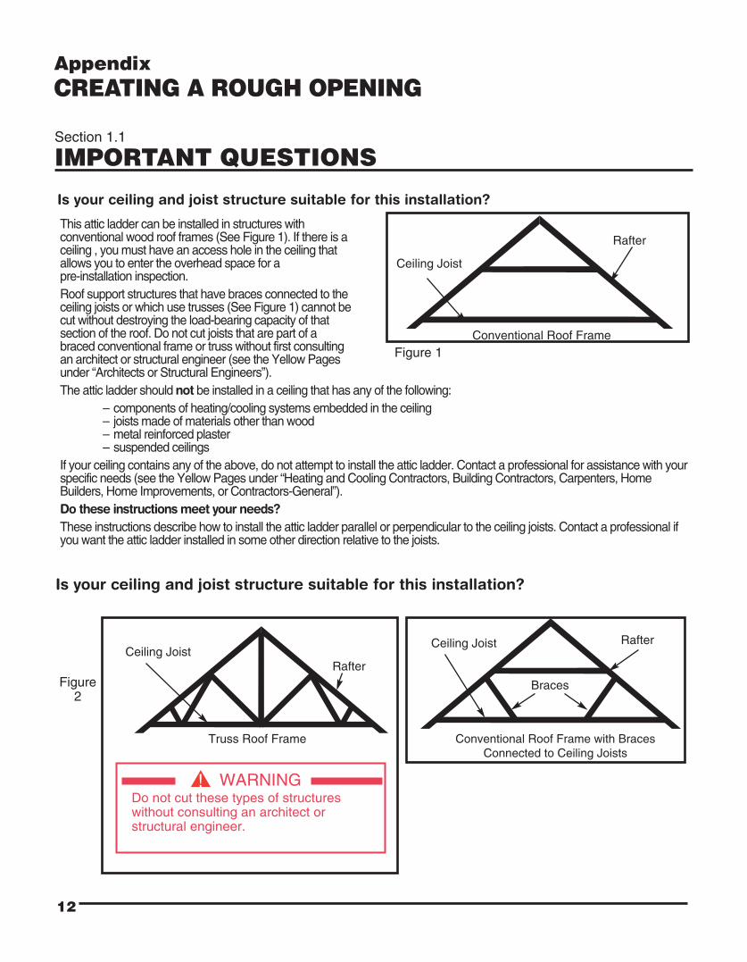
This attic ladder can be installed in structures with conventional wood roof frames (See Figure 1). If there is a ceiling , you must have an access hole in the ceiling that allows you to enter the overhead space for a pre-installation inspection.Roof support structures that have braces connected to the ceiling joists or which use trusses (See Figure 1) cannot be cut without destroying the load-bearing capacity of that section of the roof. Do not cut joists that are part of a braced conventional frame or truss without first consulting an architect or structural engineer (see the Yellow Pages under “Architects or Structural Engineers”).The attic ladder should not be installed in a ceiling that has any of the following:
– components of heating/cooling systems embedded in the ceiling– joists made of materials other than wood– metal reinforced plaster– suspended ceilings
If your ceiling contains any of the above, do not attempt to install the attic ladder. Contact a professional for assistance with yourspecific needs (see the Yellow Pages under “Heating and Cooling Contractors, Building Contractors, Carpenters, HomeBuilders, Home Improvements, or Contractors-General”).Do these instructions meet your needs?These instructions describe how to install the attic ladder parallel or perpendicular to the ceiling joists. Contact a professional ifyou want the attic ladder installed in some other direction relative to the joists.
Figure 2
12
Ceiling Joist
Rafter
Conventional Roof Frame
Is your ceiling and joist structure suitable for this installation?
AppendixCREATING A ROUGH OPENING
Figure 1
Is your ceiling and joist structure suitable for this installation?
Ceiling JoistRafter
Truss Roof Frame
Ceiling Joist Rafter
Conventional Roof Frame with BracesConnected to Ceiling Joists
Braces
Section 1.1
IMPORTANT QUESTIONS
WARNING Do not cut these types of structureswithout consulting an architect orstructural engineer.

13
Materials:• Several pieces of joist-sized lumber (the amount depends on the specific installation).• 16d sinker nails or screws of equivalent strength (24 - 60 depending on the specific installation).• 20d sinker nails or screws of equivalent strength are needed for installation where joists are cut.
Stepladder:• You need a stepladder that is tall enough so that you can get into the overhead space without stepping above the working height of the stepladder. The working height of the stepladder is two steps down from the top.• Your stepladder must also have a Load Capacity that is greater than the sum of your weight plus the weight of the attic ladder.
Tools For Creating a Rough Opening:• Torch or extension light• Claw hammer• Pencil• Hand saw / power saw• Tape measure• Framing square• Tools to cut a hole in the existing ceiling
Safety Equipment:• Gloves• Safety goggles• Dust mask
Section 1.2
TOOLS AND MATERIALS NEEDED
WARNING
Be careful when using a stepladder to climb into and out of the overhead space

Before Proceeding: You must have: a suitable ceiling and joist structure, tools and materials needed, and a level flat location in the ceiling.
Goal: To find a location free of hazards andobstructions that will provide room for the installation and use of the attic ladder.Avoid installing attic ladder over other stairs.
Step 1. Pick a potential location for installation.Check that the size of rough opening is0.57 m x 1.37 m .
Step 2. If there is no ceiling and the attic ladder willfit between the joists so that no joists needto be cut, go to Section 1.6 , page 17,“FRAMING THE ROUGH OPENING”.If there is no ceiling, but one or more joistsneed to be cut, go to Section 1.5, page 16,“CUTTING THE CEILING JOISTS”.If there is a ceiling at this location, you willneed to inspect the area above this locationas described in steps 3 and 4.
Step 3. Go into the overhead space and find thearea above your chosen location. This area may be located by:A) Listening for tapping from belowB) Measuring distances from walls or other objects common to the overhead space and the room below.
Step 4. At this location in the overhead space:
A) Check that there is enough space for you to safely move around during installation.
B) Check the overhead space for storage space adjacent to the chosen location. If walking or crawling in the overhead space is desired, make sure that there is enough room to do so.
C) Check above your chosen location for hazards andobstructions such as:- Electric wire- Pipes- Heating and cooling ducts- Furnaces- Hot water heaters or other obstructions
NOTE: To check for hazards, you will need to move insulation away fromyour chosen location. Wear a dust mask, safety goggles and gloves tokeep your body covered to prevent fine cuts from fibreglass. Gently push aside insulation to avoid stirring up dust thatmay be harmful to your eyes and lungs.
Step 5. If any hazards or obstructions are present at your chosen location, look for another location or havethe hazards or obstructions moved by professionals (see the Yellow Pages under “Electricalcontractors, Heating and Cooling contractors, and Plumbing contractors”).
Section 1.3
FINDING A SUITABLE LOCATION
Figure 3
Description
FC Floor to Ceiling Height
SC Swing Clearance
LS Landing Space
WARNINGFor your safety, watch out foroverhead hazards.
Do not stand or sit on the ceiling orinsulation covering the ceiling - theceiling is not made to support yourweight. You can fall through theceiling even though it looks solid.Only the joists can support weight.
Watch out for sharp nails stickingthrough the roof.
14
FC
*0.61 mLS
SC
WARNINGDo not drive metal nails or other conductive objects into theceiling unless you are sure they will not contact electric wires.Contact with an electric wire can be deadly.
* Recommended spacingto climb ladder
SC LS FC
1.78 m 1.22 m to1.60 m
2.34 m Min. to
3.12 m Max.

Before Proceeding: You must have a location that:
A) Is free of hazards and obstructions in the overhead space.
B) Is free of hazards in the ceiling.
C) Provides enough room for installation.
D) Provides enough room to use the attic ladder.
Goal: To cut a correct sized hole in the ceiling at the desired location.
Figure 4 Figure 5
Section 1.4
CUTTING A HOLE IN THE CEILING
15
WARNING Do not saw, cut, or hammer into the ceilinguntil you are sure that the location is free of hazards and obstructions in the ceiling and attic. Contact with an electric wire can be deadly.
Figure 6
Step 1. Prepare the room by moving furniture, covering flooring with a drop cloth and removing children and pets to a safe distance away.
Step 2. Put on safety goggles and a dust mask. These will keep pieces of ceiling particles and dust from falling into your eyes, mouth or nose as you make a starter hole and cut into the ceiling.
Step 3. With a hammer and chisel, make a starter hole near the center of the chosen location (See Figure 4).
Step 4. Enlarge the opening with a saw until you can see a joist (See Figure 5).
Step 5. Draw a rectangle the size of the rough opening on the ceiling, the size of the rough opening must be 0.57 m x 1.37 m, with one edge parallel to a joist (See Figure 6). You may do this by sawing until you reach a joist and use it as a frame of reference.
Note: Locating at least one edge of the opening along a ceiling joist will allow the joist to be used as a side of the frame you will build. This will simplify framing the rough opening.
Step 6. Cut out the rest of the ceiling within the marked outline following these instructions:
A) Do not cut any joists at this time. Cut through the ceiling only.
B) Remove the ceiling in small pieces because ceiling material can be very heavy.
Step 7. If no joists span the hole in the ceiling, go to Section 1.6, page 17 “FRAMING THE ROUGH OPENING”.
If any joists span the hole, go to Section 1.5, page 16 “CUTTING THE CEILING JOISTS”.

Section 1.5
CUTTING THE CEILING JOISTS
16
Step 1. If the room has a ceiling and you have cut the required hole, go to Step 2.
If the room has no ceiling, you will need to mark the joists according to paragraph (A) or (B) below.
(A) If the chosen location is parallel to the joists, mark the rough opening length on top of the joists (See Figure 7).Do not cut the joist at this mark.
(B) If the chosen location is perpendicular to the joists, mark the rough opening width on top of the joists (See Figure 8). Do not cut the joist at this mark.
Step 2. Cut (2) joist-sized boards long enough to span (2) joists on each side of your chosen location (See Figure 9). These boards will support the joists that will be cut and help keep the ceiling from sagging or completely collapsing while you are working in the overhead space.
Step 3. Place these boards approximately 0.61 m from the edge of your chosen location and nail (See Figure 9).
Note: The 0.61m distance is needed to give you room to hammer nails into the frame that you will build in the next section.
Before Proceeding: You must have either: Exposed joists or a correctly sized hole at the desired ceiling location.Goal: To cut out any joists that are in the way of your chosen location. Before cutting the joists, you must attach them toother joists in the overhead attic to keep the ceiling from sagging or completely collapsing.
Figure 7
Dotted Line Indicates Your ChosenLocation (Location Parallel to Joist).
Figure 8
Dotted Line Indicates Your Chosen Location(Location Perpendicular to Joist).
Figure 9
Joist SupportBoards
Nail or ScrewBoards to Each Joist

Section 1.5 (continued)
CUTTING CEILING JOISTS
17
STEP 4. Determine where the joist(s) should be cut. Figure 10 shows where to mark the joist(s) that span your chosen location. Note that the joist(s) should be marked back from the edge of your location a distance of 2 times the joist thickness (usually 7.62 cm). This leaves room for two joist-sized headers to be placed against each end of the cut joist(s) (See Figure 16 on page 19).
Note: In some homes, especially older ones, the joists may be slightly thicker than the lumber you can currently buy. If your joists have a different thickness than the lumber you will be using for the headers, you will need to mark the joists back from the edge of your location a distance of two times the header thickness instead of the joist thickness.
STEP 5. Saw through the joist(s) being careful not tocut through the ceiling and making sure the cut ends of the joist(s) are flat and vertical.
Figure 10
Dotted Line Indicates Your ChosenLocation
2 x JoistThickness
Cut Here
Cut Here
Section of Joistto be Removed
2 x Joist
Thicknes
s
Before Proceeding: You should have a space between the joists at least as large as the rough opening shownon the box. Any cut joists must be attached to uncut joists.
Goal: To create a four-sided frame the size of the rough opening using joist-sized lumber. This frame will bemade of single or double thickness headers and stringers depending upon the particular installation. The frameis necessary to support the attic ladder and to reinforce the roof and ceiling structure.
Section 1.6
FRAMING THE ROUGH OPENING
WARNING
For your safety, watch out for overhead hazards.Do not stand or sit on the ceiling or insulation covering the ceiling — the ceiling is not made to support your weight. You can fall through the ceiling even though it looks solid! Only the joists can support weight. To avoid falling through the ceiling, you may want to make a working platform by laying boards across the joist. Watch out for sharp nails sticking through the roof.

Section 1.6 (continued)
FRAMING THE ROUGH OPENING
18
Installing HeadersIf no joists have been cut, go to “Single Headers” below.
If any joists have been cut, go to “Double Headers” onpage 19.
Single HeadersSTEP 1. Measure the header length “H” between
the joists (See Figure 11).
STEP 2. Cut 2 headers this length. Use joist-sized lumber.
STEP 3. Place one of these headers at one end of your chosen location (See Figure 12). The header must fit snugly between the joists. Hammer it into position if necessary; if it is more than 1.59 mm too long, trim it. If it is more than 1.59 mm too short, cut another piece.
STEP 4. Square the header to one joist and drive (3) 16d nails through the joist and into the header. Check for squareness and drive (3) 16d nails through the other joist and into the header (See Figure 12). It is very important that header board is vertically plumb as well as horizontally square to side joists.
STEP 5. Position the second header 1.37 m from the first one and repeat Step 4 ( See Figure 13).
STEP 6. The frame for the rough opening requires four sides. The headers make up two of those sides. If your ceiling joists are spaced so that they make up the other two sides of the rough opening, check the opening for squareness by measuring across the diagonals. The measurements should be within 3.2 mm to be considered squareness (See Figure 13).
If your ceiling joists do not make up the other two sides of the rough opening, you need to install one or two additional pieces of lumber to frame the other side(s) of the rough opening, go to “Installing Stringers” on page 20.
Figure 11
H
Figure 12
Drive (3) 16d Nails into each end of the Header
Nails
Header
Joists
Figure 13 How to check for square
DiagonalMeasurements
Header
HeaderNails
1.37 m

Section 1.6 (continued)
FRAMING THE ROUGH OPENING
19
Double HeadersSTEP 1. Measure the header length “H” between
the uncut joists (See Figure14).
STEP 2. Cut 4 headers this length. Use joist-sized lumber.
STEP 3. Place one of these headers against the end of the cut joist(s) (See Figure 15). It must fit snugly between the uncut joists. Hammer it into position if necessary; if it is more than 1.59 mm too long, trim it. If it is more than 1.59 mm too short, cut another piece.
STEP 4. Square the header to the uncut joist and nail the header to the end of the cut joist(s) with (3) 16d nails (See Figure 15).
STEP 5. Check header for squareness then drive (3) 16d nails through each joist into each end of the header (See Figure 15).
STEP 6. Place a second header against the first header and nail it to the first header with (3) 16d nails between each joist (See Figure 16).
STEP 7. Drive (3) 16d nails through the joists into each end of the second header (See Figure 16).
STEP 8. Repeat steps 3-7 to install headers at the opposite end of the opening.
STEP 9. To frame the other side(s) of the rough opening, go to “Installing Stringers” on the next page.
STEP 10. Remove temporary support boards.
Cut Joist
First Header
Figure 15
Second Header
Nails
Figure 16
Nails
Figure 14
H
Uncut Joists
TemporarySupport Boards
20
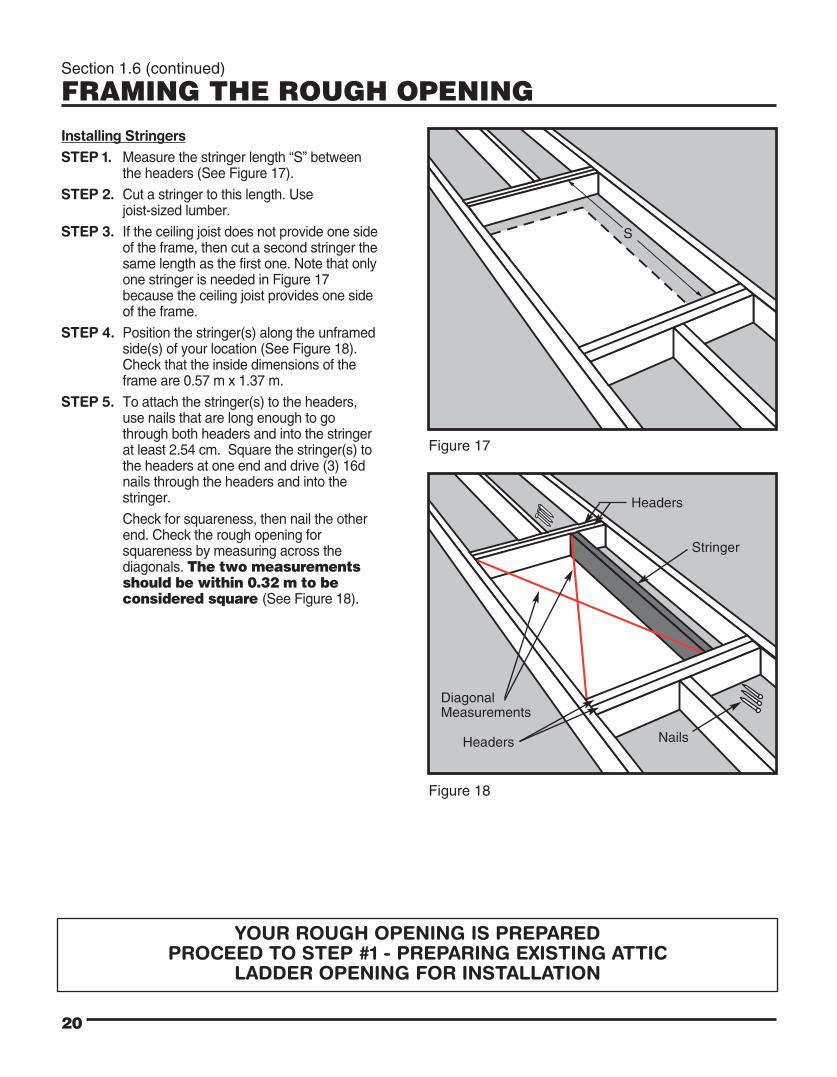
Section 1.6 (continued)
FRAMING THE ROUGH OPENING Installing StringersSTEP 1. Measure the stringer length “S” between
the headers (See Figure 17).
STEP 2. Cut a stringer to this length. Use joist-sized lumber.
STEP 3. If the ceiling joist does not provide one side of the frame, then cut a second stringer the same length as the first one. Note that only one stringer is needed in Figure 17 because the ceiling joist provides one side of the frame.
STEP 4. Position the stringer(s) along the unframed side(s) of your location (See Figure 18). Check that the inside dimensions of the frame are 0.57 m x 1.37 m.
STEP 5. To attach the stringer(s) to the headers, use nails that are long enough to go through both headers and into the stringer at least 2.54 cm. Square the stringer(s) to the headers at one end and drive (3) 16d nails through the headers and into the stringer.
Check for squareness, then nail the other end. Check the rough opening for squareness by measuring across the diagonals. The two measurements should be within 0.32 m to be considered square (See Figure 18).
Figure 18
Figure 17
S
Headers
Stringer
DiagonalMeasurements
Headers Nails
YOUR ROUGH OPENING IS PREPAREDPROCEED TO STEP #1 - PREPARING EXISTING ATTIC
LADDER OPENING FOR INSTALLATION

Replacement Parts For FS13560 Aluminium Attic Ladder
21
HARDWARE KIT
STRUTREPLACEMENT KIT
FOOT REPLACEMENTKIT
(10) 1/4" -20 Lag Bolt5.08 mm Long
(2) 1/4"-20 Hex Head Cap Screws1.91 cm Long
(2) 1/4"-20 Lock Nut
(11) 1/4" Washers
ASSIST POLE KIT
(1) Ladder AssemblyInstruction Manual
(1) Rope Assembly
(1) Instruction Sheet (1) Instruction Sheet
(1) Instruction Sheet
(2) Gas Strut Assembly
(4) Metal Straps
(2) 1/4"-20 Hex Head Cap Screws1.91 cm Long
(2) 1/4"-20 Lock Nut
(1) Left FootAssembly
(1) Machine Screw
(1) Acorn Nut
(1) Assist Pole Lower Section
(1) Assist Pole Upper Section
(1) Assist Pole Bracket
(2) 1/4"-20 Hex Head Cap Screws1.91 cm Long
(2) 1/4"-20 LockNut
(1) Right FootAssembly

© 2014 Werner Co. PN 104206-05 Rev. F 2/14