Fr/S S/10 0-000000000707 - DTIC
38
AD-AIOR 76f# NAVAL. OCEAN RESEARCH AND DEVELOPMENT ACTIVITY NAYL S-ETC Fr/S S/10 WINE MEASUJREMENT SYSTEM ISWINS).* SECTION It. IMPLANT PLAN. (U) JUN &I A L SUTHERLAND UNCLASSIPIED NA-TA T N 9 A L 7EEEhhhE 0-000000000707
Transcript of Fr/S S/10 0-000000000707 - DTIC

AD-AIOR 76f# NAVAL. OCEAN RESEARCH AND DEVELOPMENT ACTIVITY NAYL S-ETC Fr/S S/10WINE MEASUJREMENT SYSTEM ISWINS).* SECTION It. IMPLANT PLAN. (U)JUN &I A L SUTHERLAND
UNCLASSIPIED NA-TA T N 9 A L
7EEEhhhE0-000000000707

aid Development ActivityLE L>Nte9I NSTL Station, M~ilippi 39529
ANDOA
Brine Measurement System (BRIMS)A b Section II: Implant Plan
C>-
1 Alexander L. Sutherland, Jr.
I Ocean Technology Division130 Ocean Science and Technology Laboratory
JUNE 1
181 8 12 020

FOREWORD
This report presents an operations plan detailing theinstallation of the offshore portion of the Brine MeasurementSystem (BRIMS). This installation occurred during the periodSeptember through October 1979.
The report is Section II of a three-section series. Sec-tion I describes the BRIMS design, and Section III details BRIMSoperation and maintenance.
Some of the original implantment concepts, in particular,cable-laying procedures and underwater sensor mounting configura-tions, changed significantly throughout the nearly two-yearperiod in which NORDA maintained and developed the BRIMS afterinitial implantment. The reader is referred to Section III ofthis set for final cable-laying procedures and sensor mountingconfigurations.
Richard C. SwensonHead, Ocean Technology DivisionOcean Science and Technology Laboratory
%h
------------------------------------------------------------

II
ABSTRACT
The Brine Measurement System (BRIMS) was designed anddeveloped by the Naval Ocean Research and Development Activity(NORDA), Code 350, in support of the Department of Energy,Strategic Petroleum Reserve's requirement to expel brine from asalt dome for subsequent oil storage. BRIMS consists of a buoyedplatform which telemeters, to shore, data gathered by an array ofoceanographic and meteorological sensors that measure andquantify the dispersion of the brine solution emanating from apipeline ending 12.5 nautical miles at sea in the Gulf of Mexico.
The BRIMS buoy and mooring spread consists of a 10.5 toncylindrical buoy and three chain/anchor mooring legs, eachconsisting of 13.5 tons of hardware. Emanating from the buoy area series of cables which transmit data from underwater sensors.
This report details the operational planning necessary toeffectively and efficiently implant a system of this magnitudeand complexity.
S Approved tot pubuc relea.
Distrib uti u Unlirdtd
fo ulc eeU
* nlmiej , *. _ _

ACKNOWLEDGEMENT
The U.S. Coast Guard Cutter BLACKTHORN was the implantmentvessel for the BRIMS buoy and mooring system. The hard work,dedication, and good seamanship exhibited by the officers and thecrew of BLACKTHORN contributed significantly to the success ofthis operation.
Three months after the BRIMS implantment, BLACKTHORNsuffered a collision at sea and sank, with a loss of twenty-threelives.
The author wishes to express his sympathy to the families,friends, and shipmates who were affected by this tragic loss.
S..
., ...:C
ii

IICONTENTS
Page
1.0 INTRODUCTION
1.1 Background 11.2 Scope 1
1.3 Location 1
1.3.1 General 11.3.2 Specific I
1.4 Participating Organizations 5
1.5 Philosophy 51.6 Control 6
2.0 MOOR DESCRIPTION 6
2.1 Design Criteria 62.2 Component Description--Assembly Diagram 6
(includes crown lines)
2.2.1 Buoy 62.2.2 Anchor Legs 82.2.3 Anchors 8
3.0 IMPLANT SCHEDULE
4.0 BUOY AND ANCHOR LOCATION 8
4.1 Boat and Navigation Set-up 84.2 Marker Buoy Installation 13
4.2.1 Mooring Buoy Marker 134.2.2 Anchor Markers 13
5.0 SHIPMENT PREPARATIONS, NORDA 13
6.0 STAGING--GALVESTON 14
6.1 Equipment Arrival 146.2 Preparation 146.3 Deck Layout 14
7.0 BUOY MOORING OPERATIONS
7.1 Tow to Site 167.2 Temporary Mooring 16
7.3 Anchor Leg Installation 16
8.0 DIVER OPERATIONS 17
8.1 Inspection/Preparation 178.2 Marker Buoy Placement 178.3 Cable Laying/Sensor Placement 17
iii

Page
8.3.1 Flow Meter Installation 178.3.2 Current Meter Installation 188.3.3 Conductivity-Temperature Sensor 21
Installation
9.0 FINAL INSPECTION 21
APPENDICES
I. Moor Components 25II. Moor Installation Equipment 26
III. Sensor/Cable Components 27IV. Sensor Installation Equipment 28
ILLUSTRATIONS
Figure 1. Brine Measurement System 2
Figure 2. BRIMS General Location 3
Figure 3. BRIMS Sensor Layout 4
Figure 4. BRIMS Buoy General Arrangement 7
Figure 5. Typical Anchor Leg 9
Figure 6. Anchor Positions 10
Figure 7. Anchor Crown Line 11
Figure 8. Marker Buoy Line 12
Figure 9. Deck Layout 15
Figure 10. Flow Meter Installation 19
Figure 11. Flow Meter Installation 20
Figure 12. Current Meter Stand 22
Figure 13. Conductivity Temperature Sensor Mount 23
iv

r I1.0 INTRODUCTION.
1.1 BACKGROUND
Salt mounds, located along the Gulf of Mexico in the states of Texas andLoL~isiana, could, if evacuated of their salt content, form extensive, natural cavi-ties for use as fuel storage containers. The stored fuel could then be used duringperiods of reduced imported fuel from foreign sources. A brine solution, originallycontained in the mounds, would be pumped out of these mounds and deposited, viapipeline and diffuser, into the Gulf of Mexico.
The Department of Energy (DOE) has been tasked with the implementation of thisconcept. DOE, in turn, has funded the National Oceanic and Atmospheric Administra-tion (NOAA) to assess the total ecosystem impact on receiving waters and biotaresulting from the discharge of these saturated brine solutions.
NOAA has requested the services of the Naval Ocean Research and DevelopmentActivity (NORDA) to develop a system which can provide real-time display, onshore,of salinity, temperature, current, and brine flow at or near the diffuser. Thisreal-time monitoring system, dubbed BRIMS (short for Brine Measurement System), is asignificant component of the overall environmental assessment program.
The BRIMS configuration, shown in the artist's concept of Figure 1, consists ofa three-point moored buoy which is anchored over the pipeline diffuser. Bottom-mounted sensors (salinity, temperature, current, and flow) transmit their datathrough cables to the buoy. These data are then telemetered back to shore.
1.2 SCOPE
This report details the BRIMS buoy, cable, and sensor implantment plan.
1.3 LOCATION
1.3.1 General
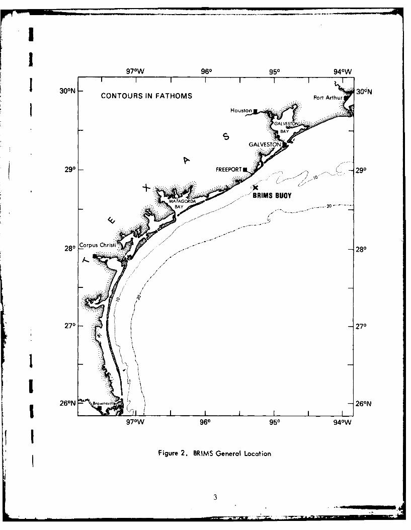
The buoy will be Im~planted at a point approximately 15 miles south of theentrance to Freeport Harbor, Freeport, Texas.
The general area location is shown in Figure 2. NOS Chart 11321 (notU included) encompasses the site location.
1.3.2 Specific
The buoy will be located 100 ft to the west of the 15th diffuser port(contngout from shore) on the brine line, see Figure 3 . The 15th port islctdat 28041 418.60611N, 95014'39.742"W. The port is marked by both a surface
and a subsurface buoy.
Depth at the site is approximately 69 ft. Water visibility at the bottom hasbeen reported to be as high as 30 ft during periods of good weather.
An exploded scale (1 inch = 200 ft) special LORAN-C (not included) has beenspecially constructed to cover the area of the BRIMS buoy and sensors.

7 UL~
V.
E41
I-C41E41L
041
41a-
01U.
A p
2 -.
L. ___
970W 960 950 940W
30I - I II II300NCONTOURS IN FATHOMS Port Arthur 3 0
Housto)n
SAY
290 FREEPORT -*.... 290
BRIMS BUOY-BA 20-
2Corpus Christi.280
2270
260N Brwsll26N
970W 960 950 94 0W
Figure 2. BRIMS General Location
3

TO SHORE
0
36" BURIED BRINE LINE
BRIMS SENSOR LAYOUT .Z
-I
15TH DIFFUSER (POSITION OF BRIMSBOUY AND FLOW METER)
1750'
// 6 CURRENT Q0 METER
?
N 8BUOY POSITION
, 280 44' 18" N*-400' 0 4- 951 14' 45" W1200'
000
LEGEND.
CONDUCTIVIFY-TEMPERATURE SENSORS
1 CAPPED DIFFUSERS (21)
WORKING DIFFUSERS (32)S0 50'
- - - SENSOR CABLE BURIED BY WATER JET
pII I I
Figure 3. BRIMS Sensor Layout
4
, , •4 :

1.4 PARTICIPATING ORGANIZATIONS
The participating organizations and points of contacts are listed below.
ORGANIZATION FUNCTION CONTACT
A. SutherlandNaval Ocean Research Projection Direction, R. Rumpf
and Development Activity Design, Equipment, (Comm.) 601-688-4742(NORDA) Coordination (FTS--Direct) 494-4742
LCDR Jim Sepel (C.O.)U. S. Coast Guard Cutter (Comm.) 713-763-2230
BLACKTHORN Buoy Installation Vessel (FTS--Direct) 527-6146
Louis Schaeffer(Comm.) 713-233-6356
Schaeffer Diving Company Diving/Cable Laying (FTS--Area) 729-4011
Capt. Reed (C.O.)U. S. Coast Guard Group BLACKTHORN Home Base (Comm.) 713-763-1635
Galveston Logistics/Staging (FTS--Direct) 527-6671
BM-1 FielU. S. Coast Guard Station Transportation to/from (Comm.) 713-233-3801
Freeport Buoy (FTS--Area) 729-4011
Richard Shaver(Comm.) 601-688-4335
NAVOCEANO (Shipping) Shipping from NSTL (FTS--Direct) 494-4385
L. B. Prino(Comm.) 713-765-9324
Port of Galveston Receiving Buoy (FTS--Area) 527-6211
' I Neil PackardDept. of Energy (Comm.) 713-223-5406
Bryan Mound (DOE/BM) User, Logistics (FTS--Direct) 527-5406
Skip MillsDept. of Energy Coordination, Diving (Comm.) 504-838-0297
New Orleans (DOE/NO) Contract Administration (FTS--Direct) 680-0297
Ed RidleyNational Oceanic and C. BurroughsAtmospheric Administration Funding and Scientific (Comm.) 202-634-7381(NOAA) Direction to Norda (FTS-Direct) 634-7381
3 1.5 PHILOSOPHY
Implant techniques are geared to the typical method of Coast Guard buoyimplantment, i.e., free running of all chain and anchors. Each leg of the mooringcan be installed as a separate operation; thus, the operation may be interrupted atfrequent points to allow for weather interruptions or re-rigging for more efficientdeployment.
5

Diving operations will be conducted to commercial (OSHA) standards. No experi-mental or untried equipment will be utilized.
Safety will be of paramount importance. The Senior NORDA Representative or anyparticipating organization supervisor may stop the job at any time if a safetyhazard exists. The job will not continue until all hazardous conditions have beencorrected.
1.6 CONTROL
Coordination and technical direction of all phases of the implant operationwill be the responsibility of the Senior NORDA Representative.
Operational supervision and direction of the buoy and mooring implantment willbe the responsibility of the Commanding Officer USCGC BLACKTHORN.
Operational supervision and direction of all diving and cable-laying operationswill be the responsibility of the assigned contractor field supervisor.
2.0 MOJOR DESCRIPTION
2.1 DESIGN CRITERIA
The mooring configuration selected is that of a Navy class-D telephone moor.This configuration consists of a three-point moor capable of safely withstanding alateral load of 75,000 lbs in any direction. The buoy itself is designed to acceptcables coming up from the sea floor through a central hawse pipe. Typically, forNavy fleet mooring purposes, the moor is used to moor ships at remote anchorages andprovide them, via the hawse pipe, a cable to a shore-based telephone line.Consequently, the moor is ideal for accepting the BRIMS sensor cables.
The moor will have a watch circle of less than 35 ft in diameter.
The buoy has a capability of rising 50 ft above the still water level. Maximumpredicted wave heights in the area are not expected to exceed 37 ft above the stillwater level.
The Navy has considerable precedence in the longevity of this type moor in opensea environments.
The entire moor weighs 106,000 lbs in air.
2.2 COMPONENT DESCRIPTION--ASSEMBLY DIAGRAM
2.2.1 Buo
The buoy is shown in Figure 4. The base of the buoy measures 7 ft in heightby 14 ft in diameter. Shipping diameter is 17 ft. The top house of the buoy is11'5S" high. Weight of the buoy is 21,000 lbs. The house weighs approximately1500 lbs.
6

BRIMS BUOYI (CUT AWAY VIEW)
ANTENNA
FOGHORN & LIGHT
HANDRAIL8" x 10' PIPE
2' WIDE PLATFORM ~
24"1PIPE
LADDER momLON HATCH
BATTERY -=HAWSE PIPE
RACK
LAD BER
Figure 4. BRIMS Buoy General Arrangement
7
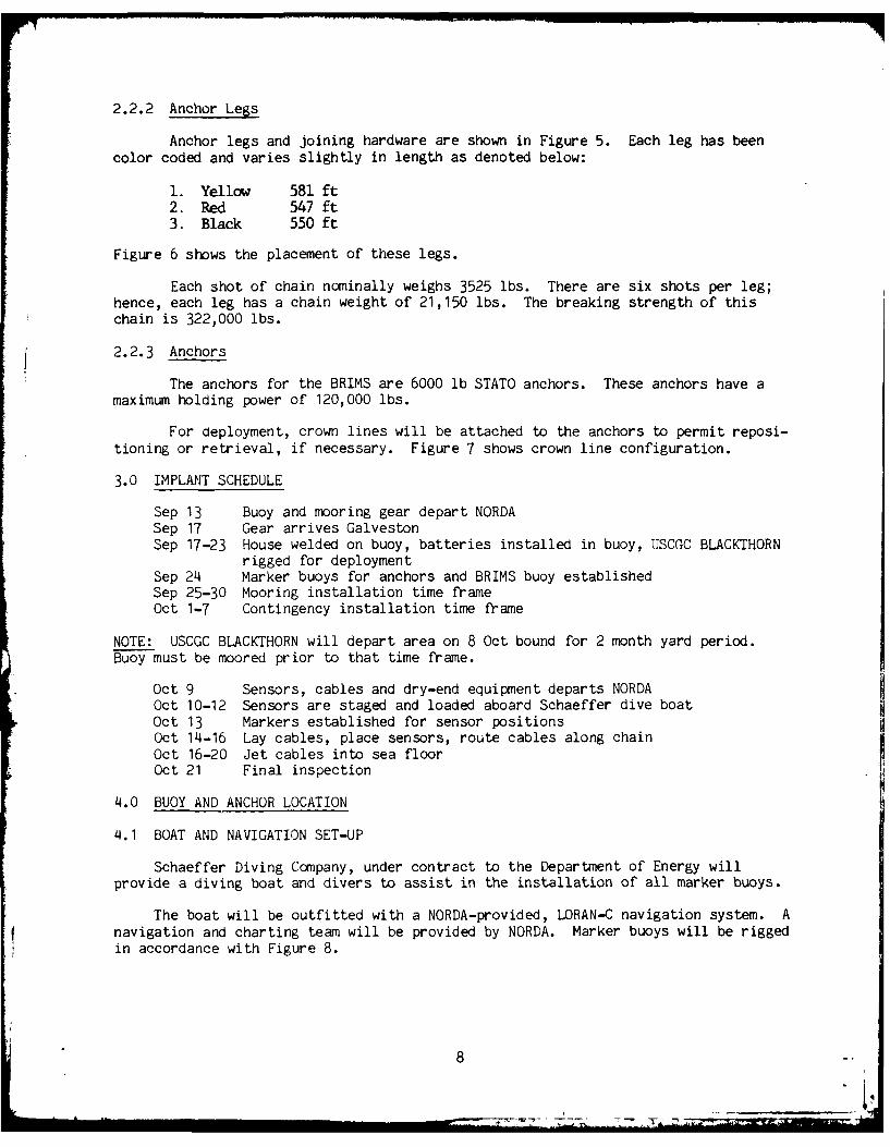
2.2.2 Anchor Legs
Anchor legs and joining hardware are shown in Figure 5. Each leg has beencolor coded and varies slightly in length as denoted below:
1. Yellow 581 ft2. Red 547 ft3. Black 550 ft
Figure 6 shows the placement of these legs.
Each shot of chain nominally weighs 3525 lbs. There are six shots per leg;hence, each leg has a chain weight of 21,150 lbs. The breaking strength of thischain is 322,000 lbs.
2.2.3 Anchors
The anchors for the BRIMS are 6000 lb STATO anchors. These anchors have amaximum holding power of 120,000 lbs.
For deployment, crown lines will be attached to the anchors to permit reposi-tioning or retrieval, if necessary. Figure 7 shows crown line configuration.
3.0 IMPLANT SCHEDULE
Sep 13 Buoy and mooring gear depart NORDASep 17 Gear arrives GalvestonSep 17-23 House welded on buoy, batteries installed in buoy, USCGC BLACKTHORN
rigged for deploymentSep 24 Marker buoys for anchors and BRIMS buoy establishedSep 25-30 Mooring installation time frameOct 1-7 Contingency installation time frame
NOTE: USCGC BLACKTHORN will depart area on 8 Oct bound for 2 month yard period.Buoy must be moored prior to that time frame.
Oct 9 Sensors, cables and dry-end equipment departs NORDAOct 10-12 Sensors are staged and loaded aboard Schaeffer dive boatOct 13 Markers established for sensor positionsOct 14-16 Lay cables, place sensors, route cables along chainOct 16-20 Jet cables into sea floorOct 21 Final inspection
4.0 BUOY AND ANCHOR LOCATION
4.1 BOAT AND NAVIGATION SET-UP
Schaeffer Diving Company, under contract to the Department of Energy willprovide a diving boat and divers to assist in the installation of all marker buoys.
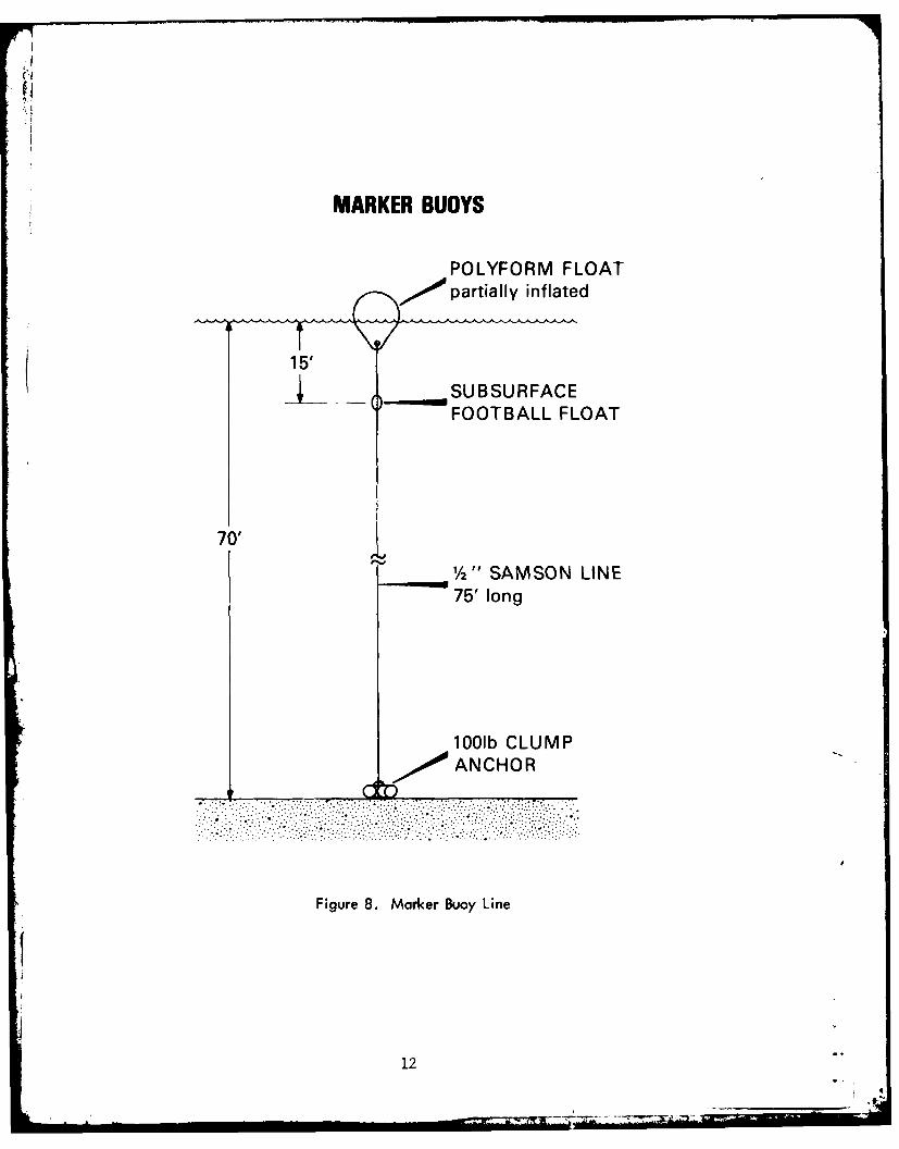
The boat will be outfitted with a NORDA-provided, LORAN-C navigation system. Anavigation and charting team will be provided by NORDA. Marker buoys will be riggedin accordance with Figure 8.
8

ANCHOR LEGS
JOINING LINK -3 "2-ANCHOR J-L
F-SHACKLE
2" CHAIN -J-L
C-J
-J-L5 SHOTS (nominally 90')
2'' CHAIN
I-J -L
1 -~J-LAll connecting HDWRSWIVELis nominally 2"
6000#STATO JL
Figure 5. Typical Anchor Leg

ANCHOR POSITIONS
PIPELINE TO SHORE
ANCHOR 315th DIFFUSER BEARING 0450FLOW METER
N28044' 18.60"
BEARING 2900
N28044' 17.75"W7501 4'40.50"
ANCHOR IBEARING 1850
Figure 6. Anchor Positions

ANCHOR CROWN LINE
,,.,POLYFORM FLOAT
11/4"0 3 STRAND~ NYLON - 150'
70'Water Depth
0.4
ANCHOR CROWN PADEYE
I Figure 7. Anchor Crown Line
II
MARKER BUOYS
POLYFORM FLOAT~'partially inflated
I 15'_ ___ SU BSU RFAC E
FOOTBALL FLOAT
70'
1/2 " SAMSON LINE75' long
1001b CLUMPANCHOR
.... ....
Figure 8. Marker Buoy Line
1
12
,. 4
4.2 MARKER BUOY INSTALLATION
4.2.1 Mooring Buoy Marker
One day prior to the planned mooring buoy installation, the diving boat withLORAN-C, marker buoys, and divers aboard, will proceed to the site of the 15thdiffuser port located at 280144118.606"N, 950114'39.742'IW. The diffuser ispresently marked with a surface float. In the event that the surface float carriesaway or is otherwise missing, the port can be distinguished by divers by thefollowing means: (1) A subsurface buoy is placed on the diffuser, (2) the checkvalve has been removed from the diffuser, and (3) the top of the cage surroundingthe diffuser has two holes burned in it aligned with the axis of the pipeline (onehole on the shoreward side, the other on the seaward side).
Divers will descend n'n the diffuser port carrying with them a compass, a 100ft distance line, and a small, temporary surface marker buoy and weight.
The divers will establish that they are on the 15th diffuser port and willmark a point 100 ft away from the diffuser, perpendicular to the axis of thepipeline on the western side of the pipe. There, they will place a temporary anchorweight and will pull up any slack in the temporary marker buoy line. The diverswill surface and a marker buoy of the configuration of Figure 8 will be lowered nextto the temporary marker. The divers will again descend on the site and will assurethat the more permanent marker is in the correct position. They will then removethe temporary marker and will return to the surface.
The installed marker establishes the position of the mooring buoy.
4.2.2 Anchor Markers
When the mooring buoy marker position has been established, its position willbe marked on a specially constructed LORAN-C chart (not included in this report).An overlay to this chart (also not included) has been prepared to denote anchorpositions relative to the mooring buoy. From this overlay, the LORAN-C coordinatesfor the anchors may be obtained. Figure 6 shows the relative anchor/mooring buoypositions. Each leg extends a horizontal distance of 525 ft from the mooring buoy.
With the anchor positions established, the boat will proceed slowly to eachanchor position, guided by the NORDA navigation team. Marker buoys will be fakedout on deck for free runninc-. Upon the word of the navigator, a marker buoy will be
free-falled, anchor first, on the desired site. Each position will be recheckedj after the marker buoy has stabilized. Divers will descend on each marker to assureno debris is in the area which would affect mooring anchor setting.
wl In the event that the LORAN-C malfunctions or is otherwise unsuitable, diverswlutilize a compass and a 525 ft distance line to establish each marker point.
5.0 SHIPMENT PREPARATIONS, NORDA
Prior to shipment of equipment from NORDA, the buoy will be prerigged in thefollowing manner: One half-shot (145 ft) of chain will be affixed to each of thethree mooring padeyes. The other end of these shots will then be brought up to thetop of the buoy. The chain will be cinched securely with synthetic line to thepadeyes on the buoy top. Care will be taken to assure that the synthetic line willnot chafe. The chain will be cinched at a point approximately 35 ft down from thebitter end, thereby providing 35 ft lazy pennants atop the buoy.
13
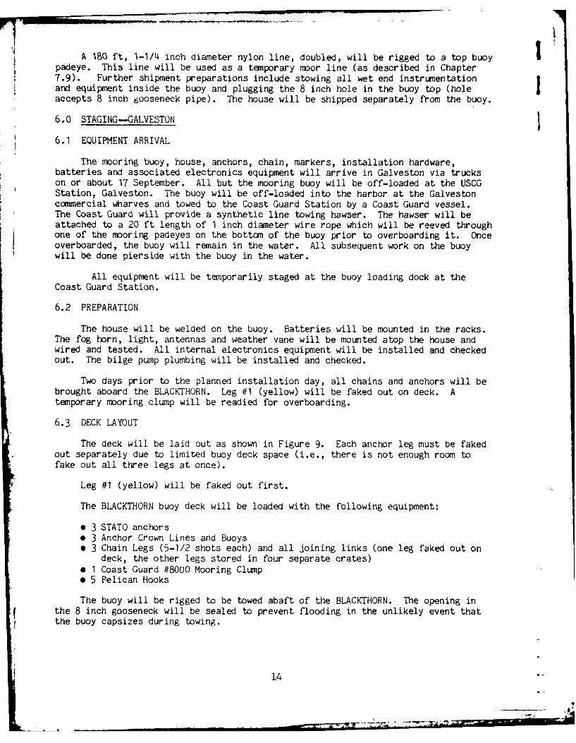
A83f,1-.1/14 icdimtrnlniedoubled, will be rigged to a top buoypadeye. This line will be used as a temporary moor line (as described in Chapter7.9). Frhrshipment preparations include stowing all wet end instrumentationand equipment inside the buoy and plugging the 8 inch hole in the buoy top (holeaccepts 8 inch 6ooseneck pipe). The house will be shipped separately from the buoy.
6.0 STAGING-GALVESTON
6.1 EQUIPMENT ARRIVAL
The mooring buoy, house, anchors, chain, markers, installation hardware,batteries and associated electronics equipment will arrive in Galveston via truckson or about 17 September. All but the mooring buoy will be off-loaded at the USCGStation, Galveston. The buoy will be off-loaded into the harbor at the Galvestoncomm~ercial wharves and towed to the Coast Guard Station by a Coast Guard vessel.The Coast Guard will provide a synthetic line towing hawser. The hawser will beattached to a 20 ft length of 1 inch diameter wire rope which will be reeved throughone of the mooring padeyes on the bottomn of the buoy prior to overboarding it. Onceoverboarded, the buoy will remain in the water. All subsequent work on the buoywill be done pierside with the buoy in the water.
All equipment will be temporarily staged at the buoy loading dock at the
Coast Guard Station.
6.2 PREPARATION
The house will be welded on the buoy. Batteries will be mounted in the racks.The fog horn, light, antennas and weather vane will be mounted atop the house andwired and tested. All internal electronics equipment will be installed and checkedout. The bilge pump plumbing will be installed and checked.
Two days prior to the planned installation day, all chains and anchors will bebrought aboard the BLACKTHORN. Leg #1 (yellow) will be faked out on deck. Atemporary mooring clump will be readied for overboarding.
6.3 DECK LAYOUT
The deck will be laid out as shown in Figure 9. Each anchor leg must be fakedout separately due to limited buoy deck space (i.e., there is not enough room tofake out all three legs at once).
Leg #1 (yellow) will be faked out first.
The BLACKTHORN buoy deck will be loaded with the following equipment:
* 3 STATO anchors0 3 Anchor Crown Lines and Buoys* 3 Chain Legs (5-1/2 shots each) and all joining links (one leg faked out on
deck, the other legs stored in four separate crates)e 1 Coast Guard #8000 Mooring Clumpe 5 Pelican Hooks
The buoy will be rigged to be towed abaft of the BLACKTHORN. The opening inthe 8 inch gooseneck will be sealed to prevent flooding in the unlikely event thatthe buoy capsizes during towing.
14

II1
I0.0000
I I 'FE0
__15

FOOTThe hawser used to tow the buoy will be rigged in the same manner as it was to
bring it around from Galveston (Section 6.1).
7.0 BUOY MOORING OPERATIONS
7.1 TOW TO SITE
The implant site is nearly 50 miles from the Coast Guard base in Galveston;hence, at an expected tow speed of ~4 knots, it would take 12-1/2 hours to get tosite. (NOTE: Virtually no data exist on the tow characteristics of this buoy;hence, tow speed is essentially an engineering estimate. If time permits, duringthe tow of the buoy around from the Galveston wharves to the Coast Guard Station,different tow speeds will be tried to assess buoy performance. If the buoy seems tohave a tendency to kite back and forth in the wake, the two 1/2 shots of chain onthe buoy that face aft may be lowered further to provide a drag stabilization.)
To allow for a 12-1/2 hour tow, the BLACKTHORN must depart Galveston on orabout 1800 hours to permit arrival on site at first light.
A tow watch will be Posted throughout the tow.
The BLACKTHORN will depart only when good weather, i.e., sea state three orless, is predicted for period in excess of 36 hours.
7.2 TEMPORARY MOORING
Once at the site,the BRIMS buoy will be maneuvered alongside the port buoy deckand secured to a position aft of the temporary mooring clump (see Fig. 9 for clunpposition). The temporary mooring line (described in 5.0) will be attached to themooring clump. The BLACKTHORN will maneuver to the buoy marker. The BRIMS buoywill be set free of the BLACKTHORN and the clump will be over-boarded. This willplace the buoy in a stable, temporary moor.
7.3 ANCHOR LEG INSTALLATION
With the BRIMS buoy in a temporary moor, the BLACKTHORN buoy deck will bereadied for deploying anchor leg #1. The STATO anchor will be hung over the side,attached to the ship's chain stopper. The anchor crown line will be tied off to therailing in bights. Any chain which had shifted during transit will be repositioned.All chain fittings will be rechecked.
The BLACKTHORN will then reposition next to the BRIMS buoy. The BLACKTHORNboom will pick up the bitter end of the nearest half shot of chain attached to thebuoy. A rigger will be on-board the BRIMS buoy and will cut the synthetic chaincinch line when the boom has the full chain load. The chain will be brought aboardthe BLACKTHORN buoy deck and will be affixed to the bitter end of the remainingchain of leg #1 faked out on deck.
The BLACKTHORN will then proceed toward the marker buoy for leg #1. Pelicanhooks shown on Figure 9 will be released sequentially. No rrore than one shot ofchain will be dropped at any one time. The chain will be stretched out prior to therelease of each pelican hook.
In a like manner, legs #2 and #3 will be faked out on deck and installed. TheBLACKTHORN will return to the BRIMS buoy. A swimmer will cut the temporary mooringline, and the mooring clump will be abandoned.
16

1 TThe anchors may be repositioned, if necessary, by heaving on the crown lines.I When the anchors are in position, the crown buoys will be removed, a small weight
will be attached to the crown line end. The line and weight will be pulled in adirection away frcm the buoy and overboarded.
This concludes the BRIMS buoy installation. The BLACKTHORN will then return
to base.
8.0 DIVER OPERATIONS
Diver operations will be conducted by Schaeffer Diving Company, Freeport,Texas, under contract to the Department of Energy. The diving support vessel is a105 ft work boat, the M/V ROCKET III. The M/V ROCKET, in addition to being a diving
support boat, has a U-frame with a 50-ton lift capacity.
8. 1 INSPECTION/PREPARATION
I Divers will proceed to the BRIMS site and, under the technical guidance of theNORDA representative, will inspect the mooring configuration. Each leg will be swumand inspected to determine that it is straight, that the chain follows a smoothcatenary with no piles of loose chain, and that the anchor flukes are deployed orready to deploy wKen loaded. If the legs need straightening or anchors needrepositioning, the crown lines will be brought back to the surface by the divers andthe M/V ROCKET will reposition as necessary. When the legs are in the properposition, the crown lines will be cut loose and brought aboard the ROCKET. Otherclean up will include removal of the temporary mooring line. The temporary mooringclump will not be removed unless it in some way would affect the permanent mooring,the brine pipeline, or sensor/cable performances.
8.2 MARKER BUOY PLACEMENT
I Marker buoys for sensor positions will be deployed using the NORDA-provided,LORAN-C for navigation. Procedures and equipment are identical to that described inChapter 4.2.2.
It is expected that diver inspection/preparation and marker buoy placement willbe done in one day.
1 8.3 CABLE LAYING/SENSOR PLACEMENT
All cables, sensors, grips, and lowering lines will be loaded aboard the
ROCKET.
The ROCKET will proceed to site and tie up to the BRIMS buoy.
Two NORDA representatives will board the BRIMS buoy. A weighted line will bethreaded down through the house and hawse pipe. A diver will bring the end of the
I weighted line out from under the buoy and back to the surface. There it will betied back into its other end, thus providing a loop through the buoy hawse andaround the outside of the buoy. This "feeder loop" will be used to pull up theIbitter ends of the signal cables through the hawse and house.8.3.1 Flow Meter Installation
The first meter to be installed will be the flow meter. The M/V ROCKET willbe tied alongside the BRIMS buoy. The flow meter cable will be faked out on the
17

deck of the ROCKET in a figure eight. A diver will enter the water and will securethe bitter end of the sensor cable to the feeder loop. The cable will be pulledaboard the buoy and fed down through the gooseneck. Approximately 150 ft of cablewill be brought aboard the buoy.
The remaining cable (approx. 170 ft) aboard the ROCKET will be lowered in abight to the bottomn. Divers will descend with the sensor mounted in the modifieddischarge hose, Figure 10. They will then mount the sensor in the 15th diffuserport, assuring that the sensor probe is properly aligned with the direction of flowin the pipe. To assist in this alignment, a prominent white stripe will be paintedon the discharge hose. This stripe must face toward the shore along the axis of thebrine line.
A 25 lb syntactic foan float will have been installed on the cableapproximately 40 ft from the flow sensor.
Divers will attach Kevlar Seamans stoppers from the chain of leg #3 to thesensor cable strength member at two points shown in Figure 11.
Final adjustments in the amount of cable slack required at the buoy will bemade. Personnel aboard the buoy will then attach a Seamnans stopper to the cable andsecure it to a tie-off point just below the gooseneck on the buoy house.
During installation, personnel aboard the BRIMS buoy will monitor the sens;orto assure that it is working. They will be in contact with the ROCKET via Motorolahandi-talkies.
8.3.2 Current Meter Installation
The ROCKET will tie up to the BRIMS buoy on the eastern side (if not alreadythere).
The current meter sensor cable (492 ft long) will be faked out in a figureeight on the ROCKET deck. The meter and stand will be on the bottom of the cablepile with a lowering line attached. The lowering line will have a small float onits bitter end.
C As done in the flow meter installation, a diver will attach the bitter end ofthe sensor cable to the feeder line under the buoy. The cable will be brought upthrough the hawse and the house and fed into the gooseneck. It will then be securedwith a Seamans stopper at the top of the buoy house.
The diver will then begin to attach the cable to chain leg #3 with Seamansstoppers spaced approximately every 100 ft. He must assure tiiat trie cable catenaryis greater than that of the chain as shown in Figure 1. tie must be particularlysure that the cable is quite slack between the buoy hawse and the first stopper.
The diver will be surface tethered and will have communications with thesurface. Cable will be payed out by hand from the surface upon the diver's command.The last stopper will be placed on the cable at a point where the chain isapproximately five feet above the sea floor.
The diver will then return to the surface, and the ROCKET will proceed alonga generally parallel path to leg #3 and slightly to the south. Sensor cable will bepayed out by hand. At the end of the cable run, the sensor and stand will belowered by the lowering line. The lowering line and buoy will then be cast off.
18

SSENSOR CABLERSTUFFIN TUBEV
HOSE(MDIFED
POYETHAN STFIGTB
POTTIN & OTM
L EXTTILLDISHAOG
DIFAUSE POTLPE
POLYUETHAN
POTIN
Figure 10. Flow Meter Installation
19
aw ------

4-j
Cu J
% 0LC) 0
L4-
-I LU -.
* U--a U-
1i 0*.0
LU,
UU)
0l LLIIE-
hZ
LU
20
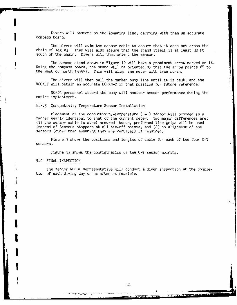
Divers will descend on the lowering line, carrying with them an accuratecompass board.
The divers will swim the sensor cable to assure that it does not cross thechain of leg #3. They will also assure that the stand itself is at least 30 ftsouth of the chain. Divers will then orient the sensor.
The sensor stand shown in Figure 12 will have a prominent arrow marked on it.Using the compass board, the stand will be oriented so that the arrow points 60 tothe west of north (3540). This will align the meter with true north.
The divers will then pull the marker buoy line until it is taut, and theROCKET will obtain an accurate LORAN-C of that position for future reference.
NORDA personnel aboard the buoy will monitor sensor performance during theentire implantment.
8.3.3 Conductivity-Temperature Sensor Installation
Placement of the conductivity-temperature (C-T) sensor will proceed in amanner nearly identical to that of the current meter. Two major differences are:(1) the sensor cable is steel armored; hence, preformed line grips will be usedinstead of Seamans stoppers at all tie-off points, and (2) no alignment of thesensors (other than assuring they are vertical) is required.
Figure 3 shows the positions and lengths of cable for each of the four C-Tsensors.
Figure 13 shows the configuration of the C-T sensor mooring.
9.0 FINAL INSPECTION
The senior NORDA Representative will conduct a diver inspection at the conple-tion of each diving day or as often as feasible.
II'
I

CURRENT METER STAND
-CUR CURENT METER
-~ 2" 0 STL PIPE - 3' long
18"x 18"x Y2"
STL PL
2"1 0 STL PIPE2' long
Figure 12. Current Meter Stand
22

KiI>1
| C-T METER STAND
1
0 - C-T METER
251b SYNTACTIC KEVLAR NETTINGFOAM FOOTBALL
FLOAT POTTED 8 PINENVIROCONCONNECTOR
I PREFORMEDGRIPS
I , ",' °x ,P
118"x 18"x 12 " STL PLw/4 - 1" 0 x 16" ALNICOMAG. LEGS
I
IFigure 13. Conductivity Temperature Sensor Mount
I2
23 A

APPENDICES
I. Moor Components
II. Moor Installation Equipment
III. Sensor/Cable Components
IV. Sensor Installation Equipment
24

I
I1APPENDIX I
Moor Componentsi1. Buoy and House 1 Ea2. Chain (2 inch) 15 Shots3. Chain (2 inch) 6 Half Shots4. Anchor Joining Links (2-1/4 inch) 6 Ea5. F-Shackles (2-1/4 inch) 3 Ea6. Swivels (2-1/4 inch) 3 Ea7. Joining Links (3-1/2 inch) 3 Ea8. Joining L~nks (2 to 2-1/4 inch) 21 Ea9. STATO Anchors (6000 lb) 3 Ea
10. Lead LS11. Batteries and Electronics LB12. Fog Horn, Light 1 Ea13. Antennas LB14. Anemometer/Stand 1 Ea
2I1
II'
| 25
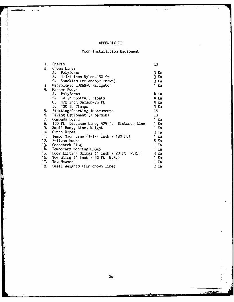
APPENDIX II
Moor Installation Equipment
1. Charts LS2. Crown Lines
A. Polyforms 3 EaB. 1-1/4 inch Nylon-150 ft 3 EaC. Shackles (to anchor crown) 3 Ea
3. Micrologic LORAN-C Navigator 1 Ea4. Marker Buoys
A. Polyforms 4 EaB. 10 lb Football Floats 4 EaC. 1/2 inch Samson-75 ft 4 EaD. 100 lb Clumps 4 Ea
5. Plotting/Charting Instruments LS6. Diving Equipment (1 person) LS7. Compass Board 1 Ea8. 100 ft Distance Line, 525 ft Distance Line 1 Ea9. Small Buoy, Line, Weight 1 Ea10. Cinch Ropes 3 Ea11. Temp. Moor Line (1-1/4 inch x 180 ft) I Ea12. Pelican Hooks 5 Ea13. Gooseneck Plug 1 Ea14. Temporary Mooring Clump 1 Ea15. Buoy Lifting Slings (1 inch x 20 ft W.R.) 3 Ea16. Tow Sling (1 inch x 20 ft W.R.) 1 Ea17. Tow Hawser 1 Ea18. Small Weights (for crown line) 3 Ea
26

III
APPENDIX III
Sensor/Cable Components
1. Flow MeterA. Sensor in Housing 1 EaB. Cable (328 ft) Married to 200 ft
Miniline 1 EaC. Kevlar Stoppers 4 EaD. 25 lb Football Floats 1 Ea
2. Current MeterA. Meter 1 EaB. Cable 492 ftC. Stoppers 6 EaD. Stand 1 Ea
3. C-T MeterA. Meters 4 EaB. 25 lb Floats bored out 4 EaC. Key Netting 4 EaD. Preformed Grips 20 EaE. Anchor Plates 4 EaF. Magnets 16 Ea
4. C-T Sensor CablesA. 1850 ft (w/potted connector) 1 EaB. 1800 ft (w/potted connector) 1 EaC. 1800 ft (w/potted connector) 1 EaD. 1350 ft (w/potted connector) 1 Ea
1II
27

APPENDIX IV
Sensor Installation Equipment
1. Charts LS2. Micrologic LORAN-C 1 Ea3. Marker Buoys
A. Polyforms 4 EaB. 10 lb Football Floats 4 EaC. 1/2 inch Samson-75 ft 4 EaD. 100 lb Clumps 4 Ea
4. Plotting Chart Instruments LS5. Diving Equipment LS6. Compass Board 1 Ea7. 1/2 inch x 60 ft Feeder Line 1 Ea8. Motorola. Handi Talkies 3 Ea9. Lowering Lines 1/2 inch x 80 ft 5 Ea10. Buoys (small) 5 Ea11. Water Jet Equipment LS
28

3 UNCLASSIFIEDSECURITY CLASSIFICATION OF THIS PAGE (When Date Entered)
READ INSTRUCTIONSREPORT DOCUMENTATION PAGE BEFORE COMPLETING FORMI. REPORT NUMBER 2. GOVT ACCESSION No. 3. RECIPIENTS CATALOG NUMBER
NORDA Technical Note 94 A V4 TITLE n S. TYPE OF REPORT & PERIOO COVERED
Brine Measurement System (BRIMS),Section IIj Implant Plan_
S. PERFORMING ORG. REPORT NUMBER
7. AUTHOR(*) -., CONTRACT OR GRANT NUMBER(&)
I . i Alexander L. Sutherland, Jr.-
9 PERFORMING ORGANIZATION NAME AND ADDRESS 10. PROGRAM ELEMENT. PROJECT, TASK
Naval Ocean Research and Development Activity AREA & WORK UIT NUVE RS
Ocean Science and Technology LaboratoryOcean Technology Division, NSTL Station, MS
11. CONTROLLING OFFICE NAME AND ADDRESS"-- 12I. P OATE
Department of Energy ) June--981Strategic Petroleum Reserve 13. NUMBEROFPAGES
New Orleans, LA 3214 MONITORING AGENCY NAME & AODRESS(II different from Controlling Office) IS. SECURITY CLASS. (of this report)
National Oceanic and Atmospheric AdministrationEnvironmental Data and Information Service UNCLASSIFIEDWashington, DC DECLASSIFICATION DOWNGRADING
W SCHEDULE
16. DISTRIBUTION STATEMENT (of this Report)
Approved for public release; distribution unlimited
17. DISTRIBUTION STATEMENT (of the abstract entered in Block 20, ift different from Report)
18 SUPPLEMENTARY NOTES
3 This report is Section II of a three volume series on the Brine MeasurementSystem (BRIMS)
19. KEY WORDS (Continue on revere side if neceesry and Identify by block number)
Buoys, moorings, implantment, oceanographic sensing, environmental sensing
I20 ABSTRACT (Continue on reveree side If necesesry mid identify by block number)
-The Brine Measurement System (BRIMS) was designed and developed by theNaval Ocean Research and Development Activity (NORDA), Code 350, in supportof the Department of Energy, Strategic Petroleum Reserve's requirement to
I expel brine from a salt dome for subsequent oil storage. BRIMS consists ofa buoyed platform which telemeters, to shore, data gathered by an array ofoceanographic and meteorological sensors which measure and quantify the
I dispersion of the brine solution emanating from a pipeline ending 12.5 milesI at sea in thp Gulf nf Myirn (MINTINIIFflI
DD I jAN 7] 1473 EDITION OF I NOV 65 IS OBSOLETE UNCLASSIFIED/ SECURITY CLASSIFICATION OF THIS PAGE (When Does Rntered)
- . " - "- - .... ' - ... -"

UNCLASSIFIED4.--,ITY CLASStFICATION OF THIS PAGE(Whon Data Entered)
'The BRIMS buoy and mooring spread consists of a large 10.5 toncylindrical buoy and three chain/anchor mooring legs, each consistingof 13.5 tons of hardware. Emanating from the buoy are a series of cableswhich transmit data from underwater sensors.
This report details the operational planning necessary to effectivelyand efficiently implant a system of this magnitude and complexity..,
L
UNCLASSIFIED
SECUPITY CLASSIFICATION OF THIS PAGE(n n Data Entered)