FRPERDPSOLÀHU IRUDFRXVWLFLQVWUXPHQWV .pdf1. FRONT PANEL - MIC IN (1, 2) CLASS-A high voltage...
12
ROY combo amplifier for acoustic instruments
Transcript of FRPERDPSOLÀHU IRUDFRXVWLFLQVWUXPHQWV .pdf1. FRONT PANEL - MIC IN (1, 2) CLASS-A high voltage...

ROYcombo amplifier
for acoustic instruments

IMPORTANT SAFETY INSTRUCTIONS
THE LIGHTNING FLASH WITH ARROWHEAD SYMBOL, WITHIN AN EQUILATERAL TRIANGLE, IS INTENDED TO ALERT THE USER TO THE PRESENCE OF UNINSULATED “DANGEROUS VOLTAGE” WITHIN THE PRODUCT ENCLOSURE THAT MAY BE OF A SUFFICIENT MAGNITUDE TO CONSITUTE A RISK OF ELECTRIC SHOCK TO PERSONS.
THE EXCLAMATION POINT WITHIN AN EQUILATERAL TRIANGLE, IS INTENDED TO ALERT THE USER TO THE PRESENCE OF IMPORTANT OPERATING AND MAINTENANCE INSTRUCTIONS IN THE LITERATURE ACCOMPANYING THE PRODUCT.
WARNING TO REDUCE THE RISK OF FIRE OR ELECTRICAL SHOCK DO NOT EXPOSE THE APPLIANCE TO RAIN OR HUMIDITY
1) Read these instructions.
2) Keep these instructions.
3) Heed all warnings.
4) Follow all instructions.
5) Do not use this apparatus near water.
6) Clean only with dry cloth.
7) Do not block any ventilation openings. Install in accordance with the manufacturer’s instructions.
8) Do not install near any heat sources such as radiators, heat registers, stoves, or other apparatus (inclu-ding amplifiers) that produce heat.
9) Do not defeat the safety purpose of the polarized or grounding-type plug. A polarized plug has two bla-des with one wider than the other. A grounding type plug has two blades and a third grounding prong. The wide blade or the third prong are provided for your safety. If the provided plug does not fit into your outlet, consult an electrician for replacement of the obsolete outlet.
10) Protect the power cord from being walked on or pinched particularly at plugs, convenience recepta-cles, and the point where they exit from the apparatus.
11) Only use attachments/accessories specified by the manufacturer.
12) Use only with the cart, stand, tripod, bracket, or table specified by the manufacturer, or sold with the apparatus. When a cart is used, use caution when moving the cart/apparatus combination to avoid injury from tip-over.
13) Unplug this apparatus during lightning storms or when unused for long periods of time.
14) Refer all servicing to qualified service personnel. Servicing is required when the apparatus has been damaged in any way, such as power-supply cord or plug is damaged, liquid has been spilled or objects have fallen into the apparatus, the apparatus has been exposed to rain or moisture, does not operate nor-mally, or has been dropped.

WARNINGS
PRECAUTIONS
WARNINGS Please read this manual carefully before using your ROY amplifier and observe all safety precautions
Keep this manual for future reference
Do not pour any liquids onto this device, or operate it in excessively humid conditions.
Do not use or install this device near sources of excessive heat. Do not expose it to direct sunlight, or position it in a dusty environment without any form of protection.
Ensure that the mains voltage does not exceed the value indicated on the back panel.
Do not use this device if either the mains cable or its plug is not in perfect condition. (Replace if necessary.)
If the mains cable needs replacing, it must be done by an appropriately qualified person. The replacement cable must be exactly the same as the original.
To avoid interference, do not use this device near power transformers, TVs, RF transmitters, electric motors or any other source of electrical energy.
Do not point a microphone towards any speakers as this could result in feedback (Larsen effect) and ultimate damage to your device.
Only use the original connection cables – if supplied with the device. Otherwise this could prove both costly and inconvenient.
To completely disconnect this device from the AC mains, remove the power cable plug from the mains socket.
When cleaning, do not use solvents (e.g acetone or alcohol). These could damage the external finish and the serigraphy.
Do not attempt to service this device. If any malfunction is detected, call the nearest technical assistance centre, or a specialist technical centre.
To maintain good ventilation, never cover or obstruct the heat sink with blankets, sofas or any other furnishings.
Always leave sufficient clearance between the heat sink and any other surface.
No flammable sources, i.e. candles, should be placed on or near the device.
This device should never be exposed to water, even in small amounts. No object containing liquids should be placed on or near the device.
This device should only be connected to a mains socket outlet that has a protective ground.
When using or installing this device, always make sure that the mains socket and the mains cable plug are easily accessible.

INTRODUCTIONCongratulations on purchasing ROY - Schertler Group’s new top-of-the-range combo amplifier for acoustic instruments. This 400W, 7-channel amp provides a powerful yet comparatively lightweight system that is perfect for both stage and studio. Equipped with a 1” horn, two 8” subwoofers and featuring the same hi-end Class A preamp found in other Schertler amplifiers, ROY delivers the rich, high-quality sound that has become synonymous with this product family, while providing the user with even greater flexibility.
ROY has 4 input channels with various mic / instrument combinations, inserts (as on a professional mixer), 3-band EQ and phantom power; an additional unbalanced instrument input channel; a stereo input channel for playback devices and an FX return / additional input channel. ROY’s Master section includes both a digital reverb with decay and a new digital Multi-Effect (on a separate buss). This intuitive control surface provides a comprehensive mixing facility for easy set-up and on-stage adjustments during performances.
Highly effective as a stand-alone portable amplification system for soloists or small groups, ROY also offers a range of output options for connecting to external systems: Add a separate subwoofer to enhance the low frequency ranges of certain instruments, or to create a compact 3-way active PA system. Connect to a mixing console for larger-scale applications. The addition of a headphone preamp provides a handy monitoring facility for both live performance and recording applications, making ROY a powerful and practical “all rounder”.
On the following pages you will find a more detailed overview of ROY’s control surface.
PRACTICAL ADVICEWhen you are using an amplified speaker, one of the most important recommendations is to avoid at all costs a distorted input signal.
In other words, when you are controlling the sound in your amplifier’s mixer section (or any other preamplifier), you must avoid reaching saturation level.
While playing your instrment or singing in the microphone, start turning up the Gain knob until the Overload LED begins to blink. At this point, turn the Gain knob back down slightly. This correctly sets the preamp level depending on your actual input signal. Now set the Master volume between 30% and 60%. With the Gain and Master levels appropriately set, you can now set the channel volume as you please.
In the case of amplified speakers, the arrival of a distorted signal (square wave) may damage the internal amplifier beyond repair, which may in turn damage the loudspeakers.
Correct use of speakers guarantees their long life.

1. FRONT PANEL - MIC IN (1, 2)
CLASS-A high voltage preamp, no integrated circuits, no NFB
ROYOLIN ¿ GAIN WARM
6
STEREOIN
MASTER
LINE OUT INSERT
DI OUT
7
VOLUME
IN
10V
LOW MID HIGH REV (AUX) VOLUME
5
MULTIEFFECT L
R
Delay + Rev
Delay 100ms
Delay 200ms
Delay 300ms
Delay 400ms
Delay 500ms
Delay 800ms
Voice doubler
Chorus slow
Chorus medium
Chorus fast
Chorus + Rev
Chorus + Delay�(150ms)
Flanger slow
Flanger medium
Flanger fast
MIXENCODERMULTIEFFECT
AUX OUT
REVER�master
DECAY
OL
OL
OL
OL
IN
IN
IN
IN
IN
GAIN RESON LOW MID HIGHINSERT REV (AUX) VOLUME
4
MULTIEFFECT48V
10V
150H�
240H�
GAIN RESON LOW MID HIGHINSERT REV (AUX) VOLUME
3
MULTIEFFECT48V
10V
150H�
240H�
FLAT
FLAT
48VINSERT GAIN LOW HIGHGAIN
300H� 3�3�H�
700H��ARAMETRIC MIDS REV (AUX) VOLUME
2
MULTIEFFECT
48VINSERT GAIN LOW HIGHGAIN
300H� 3�3�H�
700H��ARAMETRIC MIDS REV (AUX) VOLUME
1
MULTIEFFECT
1.1. MIC INPUTThis input is electronically balanced for XLR type connections. The new MIC/DYN channel is now conceived for any kind of signal sources. You can plug in vocal microphones. The electronics will adapt to any situation. No special action is required
1.2. INSERTThis stereo jack plug enables the connection of an external device (compressor, equalizer, etc.) in series to all the outputs
1.3. 48VThe amplifier’s XLR input provides 48V phantom power for use with a condenser microphone. Most condenser (and dynamic) microphones, along with some preamps, can be safely phantom powered. In certain cases however, phantom power can cause damage to a device. This tends to occur with unbalanced microphones, preamps or stompboxes that have been modified for balanced XLR use.For any doubt, please contact us to check the compatibility of your audio device before using the amplifier
1.4. GAINThis variable gain preamplifier adjusts the sensitivity level to ensure the best possible processing of the MIC signal through the channel.It is important that this input level should be set and optimised in the best way to achieve the cleanest sound possible
1.5. OVERLOADThis LED (when lit) indicates that the level of the inputsignal is too high and it might introduce distortions
1.6. HIGH, MID, LOWThese controls are devoted to high, medium and low frequency regulation. Offering cut and boost of ±15dB, they allow a wide range of tonal variations to be explored. Parametrics MID regulation, offers the possibility to cut or boost a frequency range between 300Hz and 3,3kHz. When the controls are positioned centrally there is no cut or boost of the selected frequency band
1.7. MULTIEFFECTThis rotary control sets the level of the selected effect on the channels
1.8. REVERB (AUX)This rotary control simultaneously sets the level of the digital reverb on the channels and the level of the signal sent to AUX OUT.
1.9. VOLUMEThis rotatory control regulates the channel volume
3.5
1.1 1.31.2 1.41.5
1.6 1.7 1.8 1.9

2. FRONT PANEL - MIC or INSTRUMENT IN (3, 4)
CLASS-A high voltage preamp, no integrated circuits, no NFB
ROYOLIN ¿ GAIN WARM
6
STEREOIN
MASTER
LINE OUT INSERT
DI OUT
7
VOLUME
IN
10V
LOW MID HIGH REV (AUX) VOLUME
5
MULTIEFFECT L
R
Delay + Rev
Delay 100ms
Delay 200ms
Delay 300ms
Delay 400ms
Delay 500ms
Delay 800ms
Voice doubler
Chorus slow
Chorus medium
Chorus fast
Chorus + Rev
Chorus + Delay�(150ms)
Flanger slow
Flanger medium
Flanger fast
MIXENCODERMULTIEFFECT
AUX OUT
REVER�master
DECAY
OL
OL
OL
OL
IN
IN
IN
IN
IN
GAIN RESON LOW MID HIGHINSERT REV (AUX) VOLUME
4
MULTIEFFECT48V
10V
150H�
240H�
GAIN RESON LOW MID HIGHINSERT REV (AUX) VOLUME
3
MULTIEFFECT48V
10V
150H�
240H�
FLAT
FLAT
48VINSERT GAIN LOW HIGHGAIN
300H� 3�3�H�
700H��ARAMETRIC MIDS REV (AUX) VOLUME
2
MULTIEFFECT
48VINSERT GAIN LOW HIGHGAIN
300H� 3�3�H�
700H��ARAMETRIC MIDS REV (AUX) VOLUME
1
MULTIEFFECT
3.5
2.1 2.32.22.4
2.5
2.62.7
2.8 2.9 2.10 2.11 2.12 2.13
2.1. MIC INPUTThis input is electronically balanced for XLR type connections. The new MIC/DYN channel is now conceived for any kind of signal sources. You can plug in vocal microphones. The electronics will adapt to any situation. No special action is required
2.2. INSTRUMENT INUnbalanced input for the connection of jacks (6.3mm or 1/4”), with optimal sensitivity for high level signals, the electronics will adapt to any situation. No special action is required
2.3. INSERTThis stereo jack plug enables the connection of an external device (compressor, equalizer, etc.) in series to all the outputs
2.4 48VThe amplifier’s XLR input provides 48V phantom power for use with a condenser microphone. Most condenser (and dynamic) microphones, along with some preamps, can be safely phantom powered. In certain cases however, phantom power can cause damage to a device. This tends to occur with unbalanced microphones, preamps or stompboxes that have been modified for balanced XLR use.For any doubt, please contact us to check the compatibility of your audio device before using the amplifier
2.5. 10V Phantom power supplies the Jack connector with 10V for powering electret microphones
2.6. GAINThis variable gain preamplifier adjusts the sensitivity level to ensure the best possible processing of the MIC and the INSTRUMENT IN signal through the channel.It is important that this input level should be set and optimised in the best way to achieve the cleanest sound possible
2.7. OVERLOADThis LED (when lit) indicates that the level of the inputsignal is too high AND it might introduce distortions
2.8. RESONThe Resonance (notch) filter cuts the frequncy of 150Hz/240Hz, to reduce low-frequncy feedback. Left: no attenuation (flat), Right: maximum attenuation. Use the reson switch to select the resonant frequency of the instrument (240Hz/150Hz)
2.9. RESON switch
2.10. HIGH, MID, LOWThese controls are devoted to high, medium and low frequency regulation. Offering cut and boost of ±15dB, they allow a wide range of tonal variations to be explored. When the controls are positioned centrally there is no cut or boost of the selected frequency band.
2.11. MULTIEFFECTThis rotary control sets the level of the selected effect on the channels
2.12. REVERB (AUX)This rotary control simultaneously sets the level of the digital reverb on the channels and the level of the signal sent to AUX OUT.
2.13. VOLUMEThis rotatory control regulates the channel volume

3. FRONT PANEL - INSTRUMENT IN (5)
CLASS-A high voltage preamp, no integrated circuits, no NFB
ROYOLIN ¿ GAIN WARM
6
STEREOIN
MASTER
LINE OUT INSERT
DI OUT
7
VOLUME
IN
10V
LOW MID HIGH REV (AUX) VOLUME
5
MULTIEFFECT L
R
Delay + Rev
Delay 100ms
Delay 200ms
Delay 300ms
Delay 400ms
Delay 500ms
Delay 800ms
Voice doubler
Chorus slow
Chorus medium
Chorus fast
Chorus + Rev
Chorus + Delay�(150ms)
Flanger slow
Flanger medium
Flanger fast
MIXENCODERMULTIEFFECT
AUX OUT
REVER�master
DECAY
OL
OL
OL
OL
IN
IN
IN
IN
IN
GAIN RESON LOW MID HIGHINSERT REV (AUX) VOLUME
4
MULTIEFFECT48V
10V
150H�
240H�
GAIN RESON LOW MID HIGHINSERT REV (AUX) VOLUME
3
MULTIEFFECT48V
10V
150H�
240H�
FLAT
FLAT
48VINSERT GAIN LOW HIGHGAIN
300H� 3�3�H�
700H��ARAMETRIC MIDS REV (AUX) VOLUME
2
MULTIEFFECT
48VINSERT GAIN LOW HIGHGAIN
300H� 3�3�H�
700H��ARAMETRIC MIDS REV (AUX) VOLUME
1
MULTIEFFECT
3.1. INSTRUMENT INUnbalanced input for the connection of jacks (6.3mm or 1/4”), with optimal sensitivity for high level signals. The electronics will adapt to any situation. No special action is required
3.2.PHASEIn case of feedback, or unwanted effects between different channels use the phase reverse switch
3.3. 10V Phantom power supplies the Jack connector with 10V for powering electret microphones
3.4. GAINThis variable gain preamplifier adjusts the sensitivity level to ensure the best possible processing of the INSTRUMENT IN signal through the channel.It is important that this input level should be set and optimised in the best way to achieve the cleanest sound possible
3.5. OVERLOADThis LED (when lit) indicates that the level of the input signal is too high and it might introduce distortions
3.6. WARMWhen engaged, this low-pass filter damps higher frequencies to produce a warmer sound when using bridge-mounted pickups such as the SCHERTLER STAT-Series for violin, viola, cello and double bass
3.7. HIGH, MID, LOWThese controls are devoted to high, medium and low frequency regulation. Offering cut and boost of ±15dB, they allow a wide range of tonal variations to be explored. Parametrics MIDS regulation offers the possibility to cut or boost a frequency range between 300Hz and 3,3kHz. When the controls are positioned centrally there is no cut or boost of the selected frequency band
3.8. MULTIEFFECTThis rotary control sets the level of the selected effect on the channel
3.9. REVERB (AUX)This rotary control simultaneously sets the level of the digital reverb on the channels and the level of the signal sent to AUX OUT.
3.10. VOLUMEThis rotatory control regulates the channel volume
3.13.2
3.3
3.43.5
3.63.7 3.8 3.9 3.10

4. FRONT PANEL - STEREO IN (6, 7) / MASTER
CLASS-A high voltage preamp, no integrated circuits, no NFB
ROYOLIN ¿ GAIN WARM
6
STEREOIN
MASTER
LINE OUT INSERT
DI OUT
7
VOLUME
IN
10V
LOW MID HIGH REV (AUX) VOLUME
5
MULTIEFFECT L
R
Delay + Rev
Delay 100ms
Delay 200ms
Delay 300ms
Delay 400ms
Delay 500ms
Delay 800ms
Voice doubler
Chorus slow
Chorus medium
Chorus fast
Chorus + Rev
Chorus + Delay�(150ms)
Flanger slow
Flanger medium
Flanger fast
MIXENCODERMULTIEFFECT
AUX OUT
REVER�master
DECAY
OL
OL
OL
OL
IN
IN
IN
IN
IN
GAIN RESON LOW MID HIGHINSERT REV (AUX) VOLUME
4
MULTIEFFECT48V
10V
150H�
240H�
GAIN RESON LOW MID HIGHINSERT REV (AUX) VOLUME
3
MULTIEFFECT48V
10V
150H�
240H�
FLAT
FLAT
48VINSERT GAIN LOW HIGHGAIN
300H� 3�3�H�
700H��ARAMETRIC MIDS REV (AUX) VOLUME
2
MULTIEFFECT
48VINSERT GAIN LOW HIGHGAIN
300H� 3�3�H�
700H��ARAMETRIC MIDS REV (AUX) VOLUME
1
MULTIEFFECT
4.1. STEREO INMini Jack stereo 3.5mm input for PC, MP3 and several electronic devices. The volume depends on the MASTER-VOL regulation
4.2. FX ReturnLeft and Right unbalanced jack plug for FX Return
4.3. FX Return volumeThis rotary control sets the output level on the FX Return
5.1. MASTERControl overall system volume
5.2. MUTEMute switch, cuts the audio on the master
5.3. LOW CUTWhen engaged, this filter cuts all the frequencies below 120Hz. This function is ideal if you play an instrument that generates aggressively low frequencies, it enables you to connect a subwoofer and prevent unpleasant vibration and possible damage to your ROY
5.4. Power LEDThis LED indicates when the amplifier is switched ON
5.5. DI-OUTGeneral output. XLR balanced type connector for connections of external systems. The output volume does not depend on the regulation of the MASTER-VOL but is effected by changes in individual channel volume.
5.6. DI-OUT vol.This rotary control sets the output level on the DI-OUT
5.7. AUX OUTAdditional output. This mono jack plug enables connection to other systems. In order to create a secondary mix for a stage monitor or external effect, turn the REVERB master knob (5.13) to zero and use the REVERB (AUX) knob on each channel to set the levels. You can still have an internal Reverb effect from the MULTIEFFECT (use the MULTIEFFECT knobs on each channel to set the desired amount of internal effect).
4.1 4.2 4.3
5.15.25.3
5.4
5.5
5.6 5.8
5.7 5.9
5.10
5.115.125.135.14
5.15
5.165.17

4. FRONT PANEL - STEREO IN (6, 7) / MASTER5.8. AUX OUT vol.This rotary control sets the output level on the AUX OUT
5.9 PHONESPhones output. This mono jack plug enables the connection to headphones
5.10. PHONES vol.This rotary control sets the output level on the PHONES output
5.11. INSERTThis stereo jack plug enables the connection of an external device (compressor, equalizer, etc.) in series to all the outputs
5.12. LINE OUTThis unbalanced jack plug enables the connection of external systems. The output volume depends on the regulation of the MASTER Volume knob
5.13. REVERB masterThis control regulates the general level of the digital reverb, common to all channels. The amount of the effect can be regulated individually for the single channel through the dedicated controls
5.14. DECAYThis control regulates the length of the reverb (time of the reverb from attack to silence)
5.15 MULTIEFFECT This panel shows wich one of the internal digital effects is selected. The light indicates which one of the 16 effects is engaged
5.16 MULTIEFFECT MIXThis control regulates the general level of the digital effect, common to all channels. The amount of the effect can be regulated individually for the single channel through the dedicated controls
5.17 MULTIEFFECT ENCODERThis rotary knob select the internal effect.
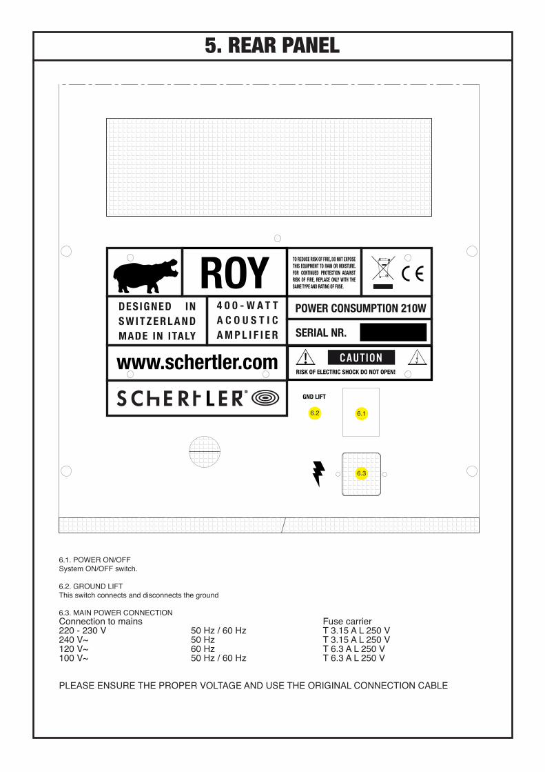
5. REAR PANEL
6.1. POWER ON/OFFSystem ON/OFF switch.
6.2. GROUND LIFTThis switch connects and disconnects the ground
6.3. MAIN POWER CONNECTIONConnection to mains Fuse carrier220 - 230 V 50 Hz / 60 Hz T 3.15 A L 250 V240 V~ 50 Hz T 3.15 A L 250 V 120 V ~ 60 Hz T 6.3 A L 250 V100 V~ 50 Hz / 60 Hz T 6.3 A L 250 V
PLEASE ENSURE THE PROPER VOLTAGE AND USE THE ORIGINAL CONNECTION CABLE
6.2 6.1
6.3
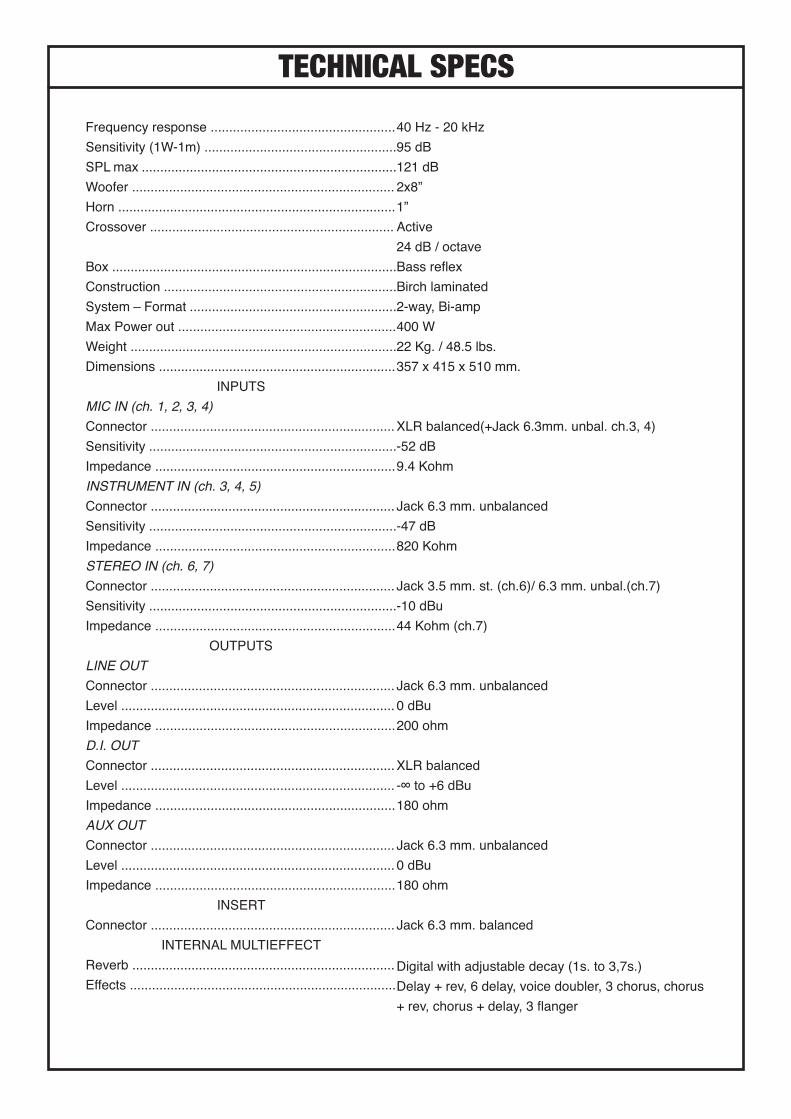
TECHNICAL SPECS40 Hz - 20 kHz95 dB121 dB2x8”1”Active 24 dB / octaveBass reflexBirch laminated2-way, Bi-amp400 W22 Kg. / 48.5 lbs.357 x 415 x 510 mm.
XLR balanced(+Jack 6.3mm. unbal. ch.3, 4) -52 dB9.4 Kohm
Jack 6.3 mm. unbalanced-47 dB820 Kohm
Jack 3.5 mm. st. (ch.6)/ 6.3 mm. unbal.(ch.7)-10 dBu44 Kohm (ch.7)
Jack 6.3 mm. unbalanced0 dBu200 ohm
XLR balanced-∞ to +6 dBu180 ohm
Jack 6.3 mm. unbalanced0 dBu180 ohm
Jack 6.3 mm. balanced
Digital with adjustable decay (1s. to 3,7s.)Delay + rev, 6 delay, voice doubler, 3 chorus, chorus + rev, chorus + delay, 3 flanger
Frequency response ..................................................Sensitivity (1W-1m) ....................................................SPL max .....................................................................Woofer .......................................................................Horn ...........................................................................Crossover ..................................................................
Box .............................................................................Construction ...............................................................System – Format ........................................................Max Power out ...........................................................Weight ........................................................................Dimensions ................................................................
INPUTSMIC IN (ch. 1, 2, 3, 4)Connector ..................................................................Sensitivity ...................................................................Impedance .................................................................INSTRUMENT IN (ch. 3, 4, 5)Connector ..................................................................Sensitivity ...................................................................Impedance .................................................................STEREO IN (ch. 6, 7)Connector ..................................................................Sensitivity ...................................................................Impedance .................................................................
OUTPUTSLINE OUTConnector ..................................................................Level ..........................................................................Impedance .................................................................D.I. OUTConnector ..................................................................Level ..........................................................................Impedance .................................................................AUX OUTConnector ..................................................................Level ..........................................................................Impedance .................................................................
INSERTConnector ..................................................................
INTERNAL MULTIEFFECTReverb .......................................................................Effects ........................................................................

ALL SCHERTLER® PRODUCTS ARE COVERED BY A LIMITED THREE-YEAR WARRANTY (FROM THE DATE OF PURCHASE) AGAINST MANUFACTURES DEFECTS. DETAILS CAN BE OBTAINED FROM YOUR LOCAL DEALER/REPRESENTATIVE. SCHERTLER SA STRONGLY BELIEVES IN “COMMON SENSE” AND THUS, MISUSE OF OUR PRODUCTS ARE NOT COVERED UNDER RIGHTS OBTAINED THROUGH OUR WARRANTY POLICY OR THAT OF INTERNATIONALLY RECOGNIZED TERMS AND CONDITIONS.
SCHERTLER SA IS CONSTANTLY AIMING TO IMPROVE ITS RANGE OF PRODUCTS THEREFORE, SCHERTLER SA RESERVES THE RIGHT TO AMEND PRODUCT SPECIFICATIONS WITHOUT NOTICE.
THE SCHERTLER® NAME/LOGO ARE REGISTERED TRADE-NAMES/ TRADEMARKS OF SCHERTLER SA, SWITZERLAND.All SCHERTLER® PRODUCTS ARE OF PROPRIETARY TECHNOLOGY AND COVERED BY ONE OF MORE WORLDWIDE PATENTS.
SIGNAL FLOW
XLR
CH.1CH.2
PHANTOM48 V
GAIN OL
3band EQparametric MID
INSERT
to MULTIEFFECT
to REVERB
CH.3CH.4
XLR
JACK
GAIN OL INSERT
VOLUME
VOLUME
JACK
PHANTOM10 V
reson
150 Hz240 Hz
PHASEGAIN
OL
3band EQVOLUME
WARMCH.5
CH.6JACK STEREO 1/8”
JACK
CH.7 JACK VOLUME
INSERT MASTER
VOLUME
VOLUME XLR
JACK
TO DI. OUT
TO PHONES
MUTE JACK
LOW CUT
TO LINE OUT
TO POWER AMP
FROM PRE-AMP
HIGH PASSFILTER
TWEETER
WOOFERS
CROSSOVER
MULTIEFFECT
ENCODER VOLUME
FROM CHANELS
REVERB
DECAY VOLUME
FROM CHANELS
TO AUX OUT
JACK
VOLUME
to MULTIEFFECT
to REVERB
PHANTOM48 V
PHANTOM10 V
3band EQ
to MULTIEFFECT
to REVERB
LIMITER POWER AMP
LOW PASSFILTER LIMITER POWER
AMP