
Front Wheel Drive Service Tool Set · Front Wheel Drive Service Tool Set No. 6537 ... Honda ......
56
Section 1: Parts List and Safety Precautions HubTamer Operating Instructions – Floating or Trapped Rotors Section 2: Vehicle Specific Operating Instructions - Domestic Section 3: Vehicle Specific Operating Instructions - Import Front Wheel Drive Service Tool Set No. 6537 Patent No. 6,357,097
Transcript of Front Wheel Drive Service Tool Set · Front Wheel Drive Service Tool Set No. 6537 ... Honda ......

Section 1: Parts List and Safety PrecautionsHubTamer Operating Instructions – Floating or Trapped Rotors
Section 2: Vehicle Specific Operating Instructions - Domestic
Section 3: Vehicle Specific Operating Instructions - Import
Front Wheel Drive Service Tool Set
No. 6537
Patent No. 6,357,097
Table of ContentsSection 1
Parts List . . . . . . . . . . . . . . . . . . . . . . . . . . . . . . . . . . . . . . . 1
Safety Precautions . . . . . . . . . . . . . . . . . . . . . . . . . . . . . . . 2
HubTamer Instructions—Floating (Removable) Rotors . . . 3
HubTamer Instructions—Trapped Rotors . . . . . . . . . . . . . . 7
Section 2 – Domestic Vehicles
Chrysler / Plymouth / Dodge . . . . . . . . . . . . . . . . . . . . . . . 11
Ford / Mercury . . . . . . . . . . . . . . . . . . . . . . . . . . . . . . . . . 13
General Motors . . . . . . . . . . . . . . . . . . . . . . . . . . . . . . . . . 17
Saturn . . . . . . . . . . . . . . . . . . . . . . . . . . . . . . . . . . . . . . . . 19
Section 3 – Import Vehicles
Acura . . . . . . . . . . . . . . . . . . . . . . . . . . . . . . . . . . . . . . . . 21
Audi . . . . . . . . . . . . . . . . . . . . . . . . . . . . . . . . . . . . . . . . . . 23
Eagle . . . . . . . . . . . . . . . . . . . . . . . . . . . . . . . . . . . . . . . . . 25
Geo . . . . . . . . . . . . . . . . . . . . . . . . . . . . . . . . . . . . . . . . . . 27
Honda . . . . . . . . . . . . . . . . . . . . . . . . . . . . . . . . . . . . . . . . 29
Hyundai . . . . . . . . . . . . . . . . . . . . . . . . . . . . . . . . . . . . . . . 31
Infiniti . . . . . . . . . . . . . . . . . . . . . . . . . . . . . . . . . . . . . . . . 33
Lexus . . . . . . . . . . . . . . . . . . . . . . . . . . . . . . . . . . . . . . . . 35
Mazda . . . . . . . . . . . . . . . . . . . . . . . . . . . . . . . . . . . . . . . . 37
Mitsubishi . . . . . . . . . . . . . . . . . . . . . . . . . . . . . . . . . . . . . 39
Nissan . . . . . . . . . . . . . . . . . . . . . . . . . . . . . . . . . . . . . . . . 41
Subaru . . . . . . . . . . . . . . . . . . . . . . . . . . . . . . . . . . . . . . . 43
Toyota . . . . . . . . . . . . . . . . . . . . . . . . . . . . . . . . . . . . . . . . 45
Volkswagen . . . . . . . . . . . . . . . . . . . . . . . . . . . . . . . . . . . . 47
Warranty Information . . . . . . . . . . . . . . . . Inside Back Cover
1
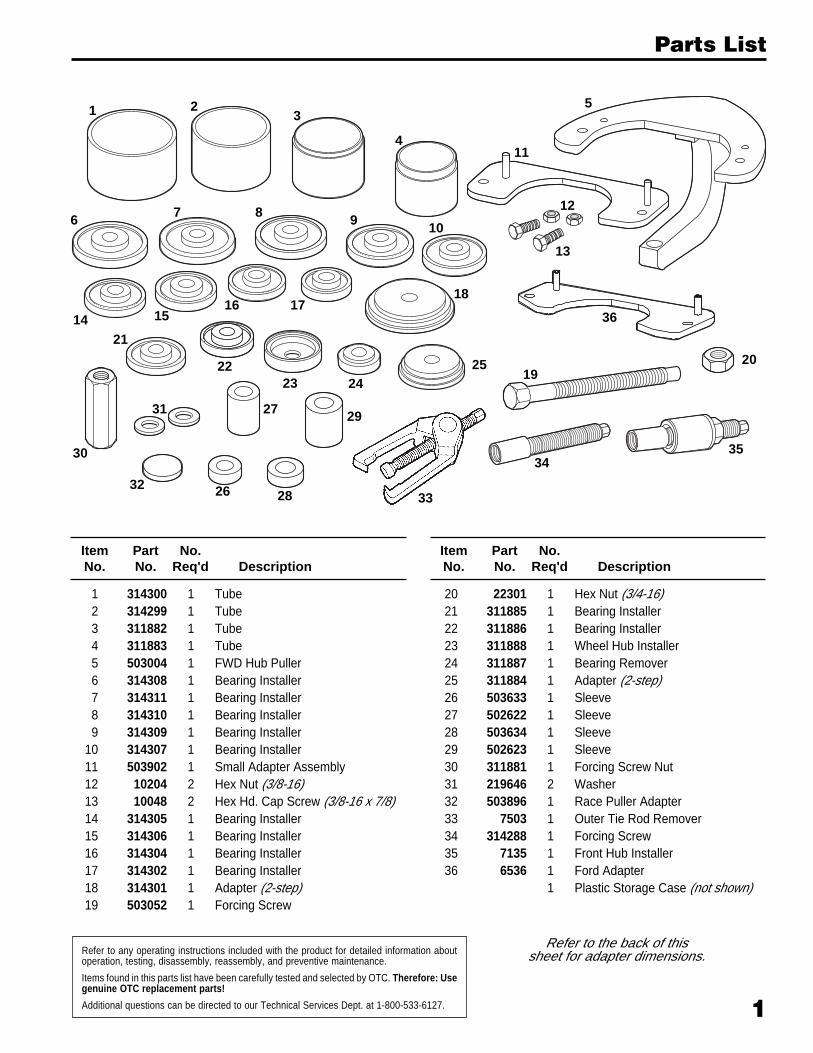
Refer to any operating instructions included with the product for detailed information aboutoperation, testing, disassembly, reassembly, and preventive maintenance.
Items found in this parts list have been carefully tested and selected by OTC. Therefore: Usegenuine OTC replacement parts!
Additional questions can be directed to our Technical Services Dept. at 1-800-533-6127.
Item Part No.No. No. Req'd Description
1 314300 1 Tube2 314299 1 Tube3 311882 1 Tube4 311883 1 Tube5 503004 1 FWD Hub Puller6 314308 1 Bearing Installer7 314311 1 Bearing Installer8 314310 1 Bearing Installer9 314309 1 Bearing Installer
10 314307 1 Bearing Installer11 503902 1 Small Adapter Assembly12 10204 2 Hex Nut (3/8-16)13 10048 2 Hex Hd. Cap Screw (3/8-16 x 7/8)14 314305 1 Bearing Installer15 314306 1 Bearing Installer16 314304 1 Bearing Installer17 314302 1 Bearing Installer18 314301 1 Adapter (2-step)19 503052 1 Forcing Screw
20 22301 1 Hex Nut (3/4-16)21 311885 1 Bearing Installer22 311886 1 Bearing Installer23 311888 1 Wheel Hub Installer24 311887 1 Bearing Remover25 311884 1 Adapter (2-step)26 503633 1 Sleeve27 502622 1 Sleeve28 503634 1 Sleeve29 502623 1 Sleeve30 311881 1 Forcing Screw Nut31 219646 2 Washer32 503896 1 Race Puller Adapter33 7503 1 Outer Tie Rod Remover34 314288 1 Forcing Screw35 7135 1 Front Hub Installer36 6536 1 Ford Adapter
1 Plastic Storage Case (not shown)
Item Part No.No. No. Req'd Description
Parts List
1
24
23
4
5
6 7 8 9 10
11
12
13
14 1516 17
18
1920
21
2322 25
26
27
28
29
30
31
3233
3435
Refer to the back of thissheet for adapter dimensions.
36

2
Part No. Dim. "A" Dim. "B" Dim. "C" Dim. "D"
311885 .750 .781 1.540 2.960
311886 .750 .781 1.500 2.625
311887 .680 .781 1.500 2.188
314302 .750 .781 1.310 2.500
314304 .750 .781 1.360 2.780
314305 .750 .781 1.480 2.820
314306 .750 .781 1.640 2.820
314307 .750 .781 1.480 2.900
314308 .750 .781 1.870 3.480
314309 .750 .781 1.620 3.055
314310 .750 .781 1.620 3.210
314311 .750 .781 1.670 3.290
311882 2.500 3.060 3.190 3.250
311883 2.500 2.750 2.955 3.000
314299 2.500 3.250 N/A 3.625
314300 2.500 3.750 N/A 4.000
"A"
"B""C"
"D"
"A"
"C""B""D"
Adapter Dimensions and Safety Precautions
Safety Precautions Warning: To prevent personal injury,
• Read, understand, and follow all safety precautions and instructions includedwith this tool. If the operator cannot read English, operating instructions andsafety precautions must be read and discussed in the operator's nativelanguage.
- Si el operador no puede leer inglés, las instrucciones de operación y lasprecauciones de seguridad deberán leerse y comentarse en el idioma nativodel operador.
- Si l’utilisateur ne peut lire l’anglais, les instructions et les consignes desécurité doivent lui être expliquées dans sa langue maternelle.
• Wear eye protection that meets ANSI Z87.1 and OSHA standards.
• Cover the work with a protective blanket (see OTC catalog) or canvas, becauseapplying force to a part can cause breakage.
3
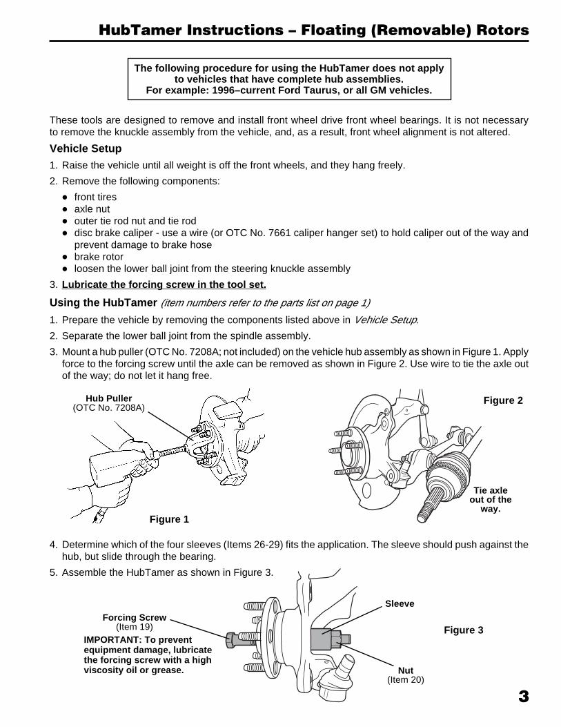
These tools are designed to remove and install front wheel drive front wheel bearings. It is not necessaryto remove the knuckle assembly from the vehicle, and, as a result, front wheel alignment is not altered.
Vehicle Setup1. Raise the vehicle until all weight is off the front wheels, and they hang freely.
2. Remove the following components:
• front tires• axle nut• outer tie rod nut and tie rod• disc brake caliper - use a wire (or OTC No. 7661 caliper hanger set) to hold caliper out of the way and
prevent damage to brake hose• brake rotor• loosen the lower ball joint from the steering knuckle assembly
3. Lubricate the forcing screw in the tool set.
Using the HubTamer (item numbers refer to the parts list on page 1)
1. Prepare the vehicle by removing the components listed above in Vehicle Setup.
2. Separate the lower ball joint from the spindle assembly.
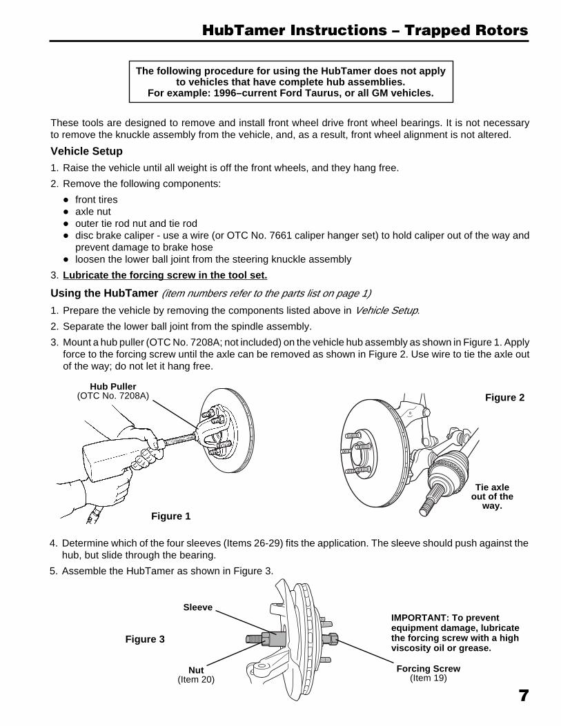
3. Mount a hub puller (OTC No. 7208A; not included) on the vehicle hub assembly as shown in Figure 1. Applyforce to the forcing screw until the axle can be removed as shown in Figure 2. Use wire to tie the axle outof the way; do not let it hang free.
HubTamer Instructions – Floating (Removable) Rotors
The following procedure for using the HubTamer does not applyto vehicles that have complete hub assemblies.
For example: 1996–current Ford Taurus, or all GM vehicles.
4. Determine which of the four sleeves (Items 26-29) fits the application. The sleeve should push against thehub, but slide through the bearing.
5. Assemble the HubTamer as shown in Figure 3.
Hub Puller(OTC No. 7208A)
Figure 1
Tie axleout of the
way.
Figure 2
Forcing Screw(Item 19)
Sleeve
Nut(Item 20)
Figure 3IMPORTANT: To preventequipment damage, lubricatethe forcing screw with a highviscosity oil or grease.
4
HubTamer Instructions – Floating (Removable) Rotors
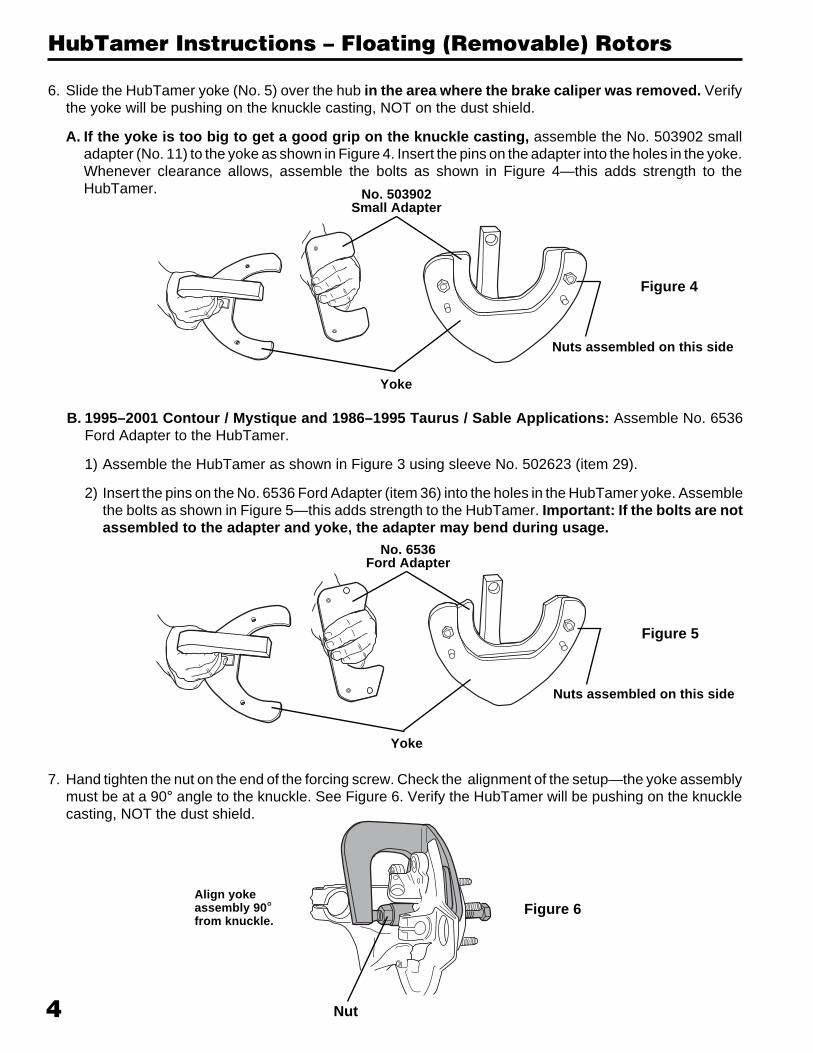
6. Slide the HubTamer yoke (No. 5) over the hub in the area where the brake caliper was removed. Verifythe yoke will be pushing on the knuckle casting, NOT on the dust shield.
A. If the yoke is too big to get a good grip on the knuckle casting, assemble the No. 503902 smalladapter (No. 11) to the yoke as shown in Figure 4. Insert the pins on the adapter into the holes in the yoke.Whenever clearance allows, assemble the bolts as shown in Figure 4—this adds strength to theHubTamer. No. 503902
Small Adapter
Yoke
Nuts assembled on this side
Figure 4
B. 1995–2001 Contour / Mystique and 1986–1995 Taurus / Sable Applications: Assemble No. 6536Ford Adapter to the HubTamer.
1) Assemble the HubTamer as shown in Figure 3 using sleeve No. 502623 (item 29).
2) Insert the pins on the No. 6536 Ford Adapter (item 36) into the holes in the HubTamer yoke. Assemblethe bolts as shown in Figure 5—this adds strength to the HubTamer. Important: If the bolts are notassembled to the adapter and yoke, the adapter may bend during usage.
No. 6536Ford Adapter
Yoke
Nuts assembled on this side
Figure 5
Nut
7. Hand tighten the nut on the end of the forcing screw. Check the alignment of the setup—the yoke assemblymust be at a 90° angle to the knuckle. See Figure 6. Verify the HubTamer will be pushing on the knucklecasting, NOT the dust shield.
Figure 6Align yokeassembly 90°from knuckle.
5
HubTamer Instructions – Floating (Removable) Rotors
Impact wrench& socket usedon forcing screw
Wrenchused on nut
Figure 7
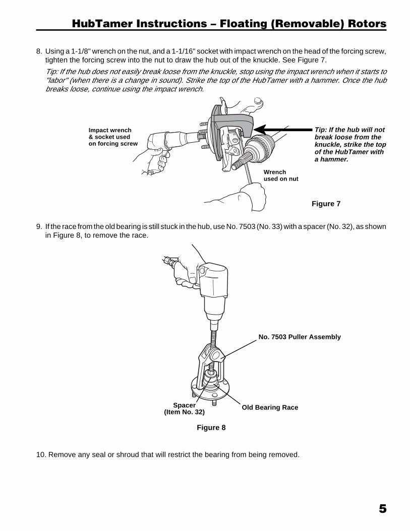
8. Using a 1-1/8" wrench on the nut, and a 1-1/16" socket with impact wrench on the head of the forcing screw,tighten the forcing screw into the nut to draw the hub out of the knuckle. See Figure 7.
Tip: If the hub does not easily break loose from the knuckle, stop using the impact wrench when it starts to"labor" (when there is a change in sound). Strike the top of the HubTamer with a hammer. Once the hubbreaks loose, continue using the impact wrench.
Tip: If the hub will notbreak loose from theknuckle, strike the topof the HubTamer witha hammer.
lllll
10. Remove any seal or shroud that will restrict the bearing from being removed.
9. If the race from the old bearing is still stuck in the hub, use No. 7503 (No. 33) with a spacer (No. 32), as shownin Figure 8, to remove the race.
Figure 8
No. 7503 Puller Assembly
Old Bearing RaceSpacer(Item No. 32)
6
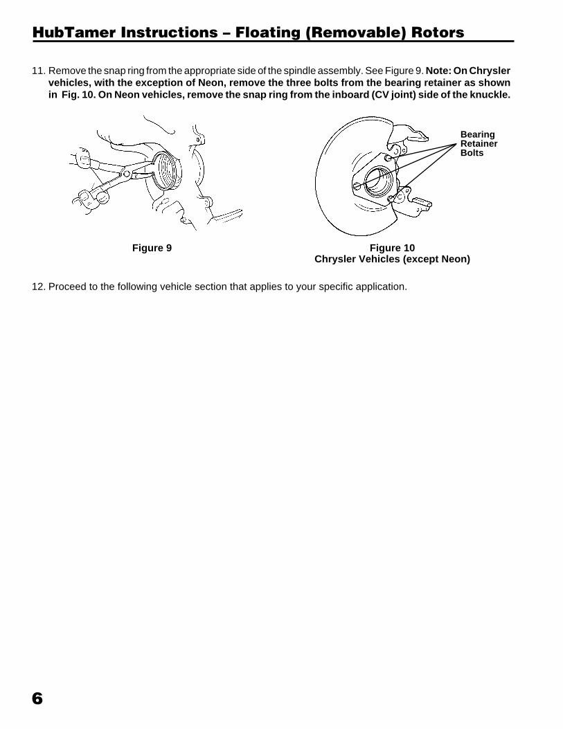
11. Remove the snap ring from the appropriate side of the spindle assembly. See Figure 9. Note: On Chryslervehicles, with the exception of Neon, remove the three bolts from the bearing retainer as shownin Fig. 10. On Neon vehicles, remove the snap ring from the inboard (CV joint) side of the knuckle.
Figure 9 Figure 10Chrysler Vehicles (except Neon)
BearingRetainerBolts
HubTamer Instructions – Floating (Removable) Rotors
12. Proceed to the following vehicle section that applies to your specific application.
7
These tools are designed to remove and install front wheel drive front wheel bearings. It is not necessaryto remove the knuckle assembly from the vehicle, and, as a result, front wheel alignment is not altered.
Vehicle Setup1. Raise the vehicle until all weight is off the front wheels, and they hang free.
2. Remove the following components:
• front tires• axle nut• outer tie rod nut and tie rod• disc brake caliper - use a wire (or OTC No. 7661 caliper hanger set) to hold caliper out of the way and
prevent damage to brake hose• loosen the lower ball joint from the steering knuckle assembly
3. Lubricate the forcing screw in the tool set.
Using the HubTamer (item numbers refer to the parts list on page 1)
1. Prepare the vehicle by removing the components listed above in Vehicle Setup.
2. Separate the lower ball joint from the spindle assembly.
3. Mount a hub puller (OTC No. 7208A; not included) on the vehicle hub assembly as shown in Figure 1. Applyforce to the forcing screw until the axle can be removed as shown in Figure 2. Use wire to tie the axle outof the way; do not let it hang free.
HubTamer Instructions – Trapped Rotors
The following procedure for using the HubTamer does not applyto vehicles that have complete hub assemblies.
For example: 1996–current Ford Taurus, or all GM vehicles.
Hub Puller(OTC No. 7208A)
Figure 1
Tie axleout of the
way.
Figure 2
4. Determine which of the four sleeves (Items 26-29) fits the application. The sleeve should push against thehub, but slide through the bearing.
5. Assemble the HubTamer as shown in Figure 3.
Forcing Screw(Item 19)
Sleeve
Nut(Item 20)
Figure 3
IMPORTANT: To preventequipment damage, lubricatethe forcing screw with a highviscosity oil or grease.
8
HubTamer Instructions – Trapped Rotors
6. Slide the HubTamer yoke (No. 5) over the hub in the area where the brake caliper was removed.
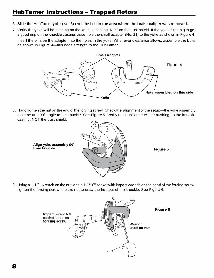
7. Verify the yoke will be pushing on the knuckle casting, NOT on the dust shield. If the yoke is too big to geta good grip on the knuckle casting, assemble the small adapter (No. 11) to the yoke as shown in Figure 4.
Insert the pins on the adapter into the holes in the yoke. Whenever clearance allows, assemble the boltsas shown in Figure 4—this adds strength to the HubTamer.
Small Adapter
Nuts assembled on this side
Figure 4
Yoke
8. Hand tighten the nut on the end of the forcing screw. Check the alignment of the setup—the yoke assemblymust be at a 90° angle to the knuckle. See Figure 5. Verify the HubTamer will be pushing on the knucklecasting, NOT the dust shield.
Figure 5
Figure 6
9. Using a 1-1/8" wrench on the nut, and a 1-1/16" socket with impact wrench on the head of the forcing screw,tighten the forcing screw into the nut to draw the hub out of the knuckle. See Figure 6.
Align yoke assembly 90°from knuckle.
Wrenchused on nut
Impact wrench &socket used onforcing screw
9
HubTamer Instructions – Trapped Rotors
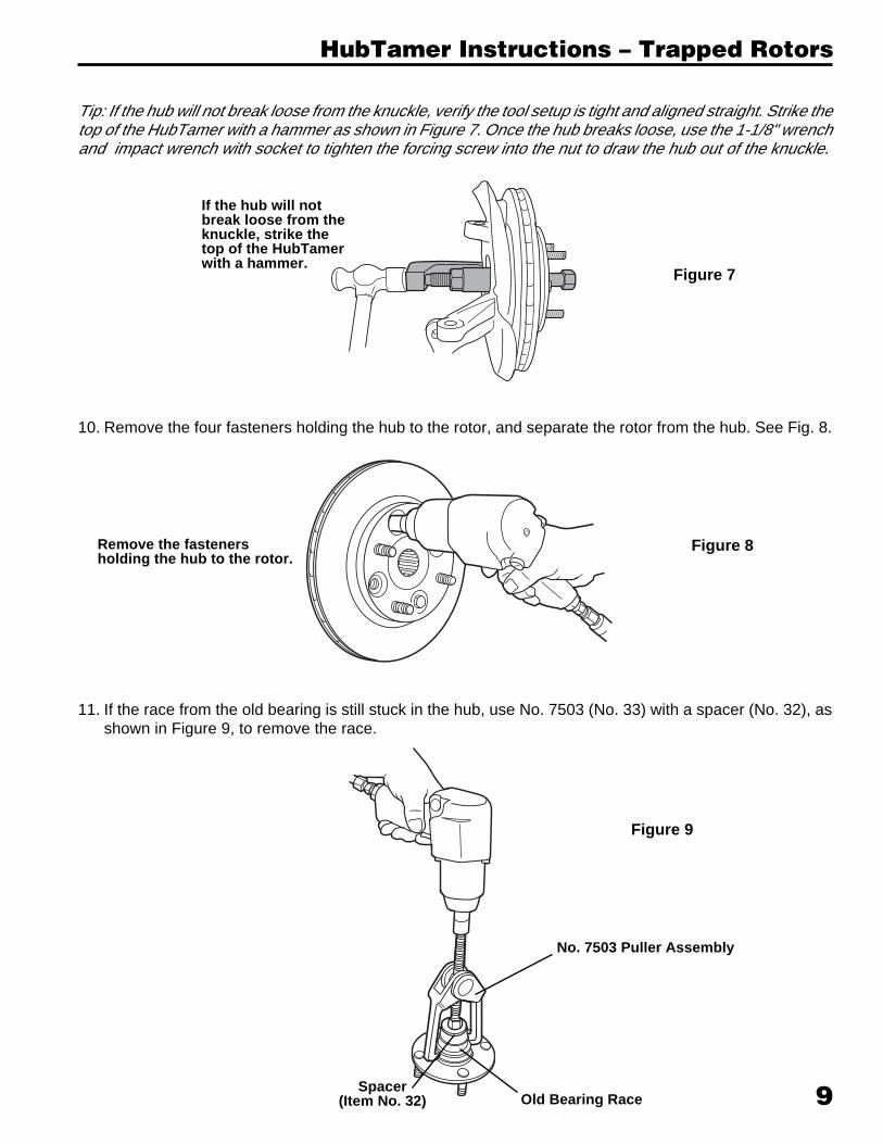
Tip: If the hub will not break loose from the knuckle, verify the tool setup is tight and aligned straight. Strike thetop of the HubTamer with a hammer as shown in Figure 7. Once the hub breaks loose, use the 1-1/8" wrenchand impact wrench with socket to tighten the forcing screw into the nut to draw the hub out of the knuckle.
Figure 7
10. Remove the four fasteners holding the hub to the rotor, and separate the rotor from the hub. See Fig. 8.
Figure 8
If the hub will notbreak loose from theknuckle, strike thetop of the HubTamerwith a hammer.
Remove the fastenersholding the hub to the rotor.
11. If the race from the old bearing is still stuck in the hub, use No. 7503 (No. 33) with a spacer (No. 32), asshown in Figure 9, to remove the race.
Figure 9
No. 7503 Puller Assembly
Old Bearing RaceSpacer
(Item No. 32)
10
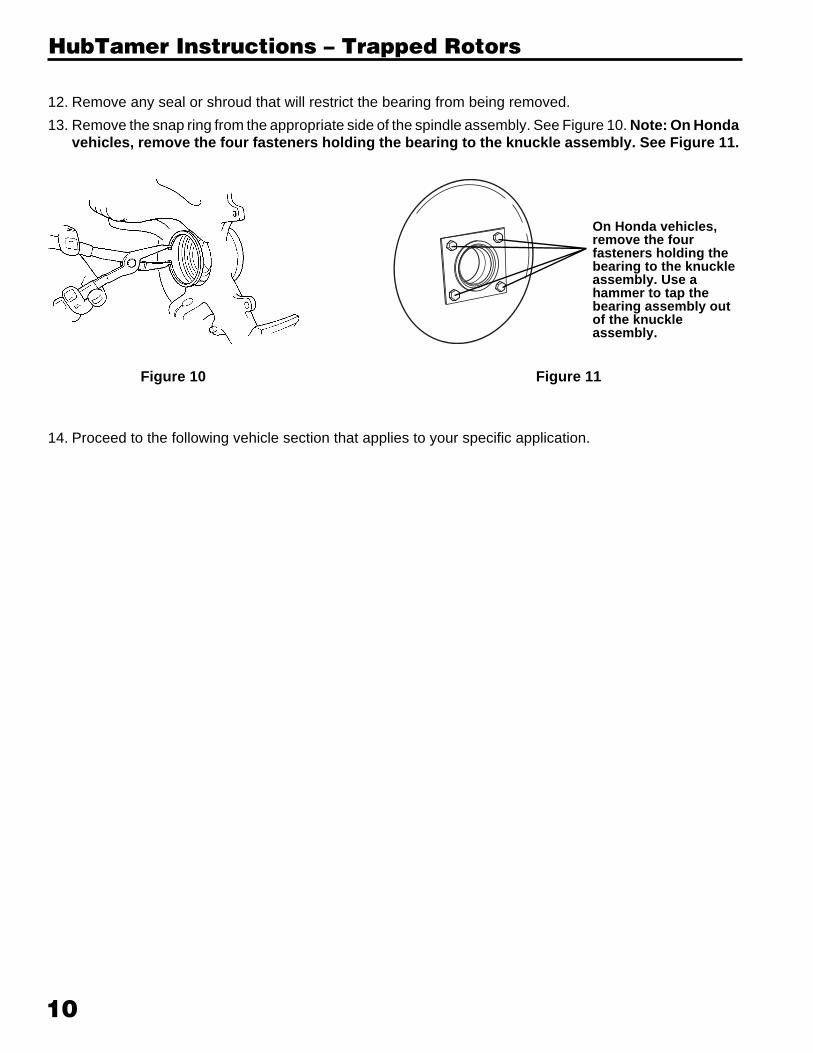
12. Remove any seal or shroud that will restrict the bearing from being removed.
13. Remove the snap ring from the appropriate side of the spindle assembly. See Figure 10. Note: On Hondavehicles, remove the four fasteners holding the bearing to the knuckle assembly. See Figure 11.
HubTamer Instructions – Trapped Rotors
14. Proceed to the following vehicle section that applies to your specific application.
Figure 10 Figure 11
On Honda vehicles,remove the fourfasteners holding thebearing to the knuckleassembly. Use ahammer to tap thebearing assembly outof the knuckleassembly.

Section 2: Vehicle Specific Operating Instructions - Domestic
Front Wheel Drive Service Tool Set
No. 6537
Patent No. 6,357,097

Table of ContentsSection 1
Parts List . . . . . . . . . . . . . . . . . . . . . . . . . . . . . . . . . . . . . . . 1
Safety Precautions . . . . . . . . . . . . . . . . . . . . . . . . . . . . . . . 2
HubTamer Instructions—Floating (Removable) Rotors . . . 3
HubTamer Instructions—Trapped Rotors . . . . . . . . . . . . . . 7
Section 2 – Domestic Vehicles
Chrysler / Plymouth / Dodge . . . . . . . . . . . . . . . . . . . . . . . 11
Ford / Mercury . . . . . . . . . . . . . . . . . . . . . . . . . . . . . . . . . 13
General Motors . . . . . . . . . . . . . . . . . . . . . . . . . . . . . . . . . 17
Saturn . . . . . . . . . . . . . . . . . . . . . . . . . . . . . . . . . . . . . . . . 19
Section 3 – Import Vehicles
Acura . . . . . . . . . . . . . . . . . . . . . . . . . . . . . . . . . . . . . . . . 21
Audi . . . . . . . . . . . . . . . . . . . . . . . . . . . . . . . . . . . . . . . . . . 23
Eagle . . . . . . . . . . . . . . . . . . . . . . . . . . . . . . . . . . . . . . . . . 25
Geo . . . . . . . . . . . . . . . . . . . . . . . . . . . . . . . . . . . . . . . . . . 27
Honda . . . . . . . . . . . . . . . . . . . . . . . . . . . . . . . . . . . . . . . . 29
Hyundai . . . . . . . . . . . . . . . . . . . . . . . . . . . . . . . . . . . . . . . 31
Infiniti . . . . . . . . . . . . . . . . . . . . . . . . . . . . . . . . . . . . . . . . 33
Lexus . . . . . . . . . . . . . . . . . . . . . . . . . . . . . . . . . . . . . . . . 35
Mazda . . . . . . . . . . . . . . . . . . . . . . . . . . . . . . . . . . . . . . . . 37
Mitsubishi . . . . . . . . . . . . . . . . . . . . . . . . . . . . . . . . . . . . . 39
Nissan . . . . . . . . . . . . . . . . . . . . . . . . . . . . . . . . . . . . . . . . 41
Subaru . . . . . . . . . . . . . . . . . . . . . . . . . . . . . . . . . . . . . . . 43
Toyota . . . . . . . . . . . . . . . . . . . . . . . . . . . . . . . . . . . . . . . . 45
Volkswagen . . . . . . . . . . . . . . . . . . . . . . . . . . . . . . . . . . . . 47
Warranty Information . . . . . . . . . . . . . . . . Inside Back Cover
11
Chrysler / Plymouth / Dodge
3142
99
3143
00
3143
01
3143
02
3143
04
3143
05
3143
06
3143
07
3143
08
3143
09
3143
10
3143
11
3118
82
3118
83
3118
84
3118
85
3118
86
3118
87
3118
88R = RemoveI = Install
R I RI I RI I
R I RI I RI I
R I RI I RI I
R RI I RI I
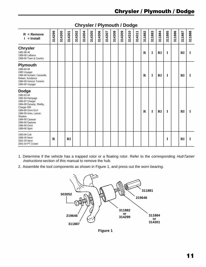
Chrysler1982-88 All1989-90 LeBaron1989-90 Town & Country
Plymouth1980-83 All1983 Voyager1984-90 Acclaim, Caravelle,Reliant, Sundance1984-90 Horizon Turismo1984-90 Voyager
Dodge1980-83 All1982-84 Rampage1984-87 Charger1984-89 Dynasty, Shelby,Charger 6001984-89 Omni GLH1984-90 Aries, Lancer,Shadow1984-90 Caravan1984-90 Daytona1984-90 Omni1989-90 Spirit
1993-94 Colt1995-00 Neon2001-04 Neon2001-04 PT Cruiser
Chrysler / Plymouth / Dodge
1. Determine if the vehicle has a trapped rotor or a floating rotor. Refer to the corresponding HubTamerInstructions section of this manual to remove the hub.
2. Assemble the tool components as shown in Figure 1, and press out the worn bearing.
503052
Figure 1
311881
219646
311884or
314301
311882or
314299219646
311887

12
Chrysler / Plymouth / Dodge
3. Lightly lubricate the new bearing, and position itfor installation with the tool componentsassembled as shown in Figure 2. Press thebearing into the spindle assembly until it bottoms.
4. Fasten the bearing retainer in place using thebearing retainer bolts. (On Neon vehicles, installthe snap ring in the knuckle.)
5. Assemble tool components as shown in Figure3. Lightly oil the hub assembly, and install thehub.
Important: The bearing installer must beassembled with the flat side toward the bearingand the small diameter pilot on the side awayfrom the bearing.
6. Assemble the remaining vehicle componentsthat were removed for bearing replacement:
• lower ball joint to steering knuckle assembly• brake rotor• disc brake caliper• outer tie rod nut and tie rod• axle nut• front tires
503052
311884or
314301
219646
New Bearing
311885
219646311881
311883(not used forColt or Neon)
Figure 2
503052
219646
311887(flat side toward bearing)
219646
311881
311888
Figure 3
13
3142
99
3143
00
3143
01
3143
02
3143
04
3143
05
3143
06
3143
07
3143
08
3143
09
3143
10
3143
11
3118
82
3118
83
3118
84
3118
85
3118
86
3118
87
3118
88
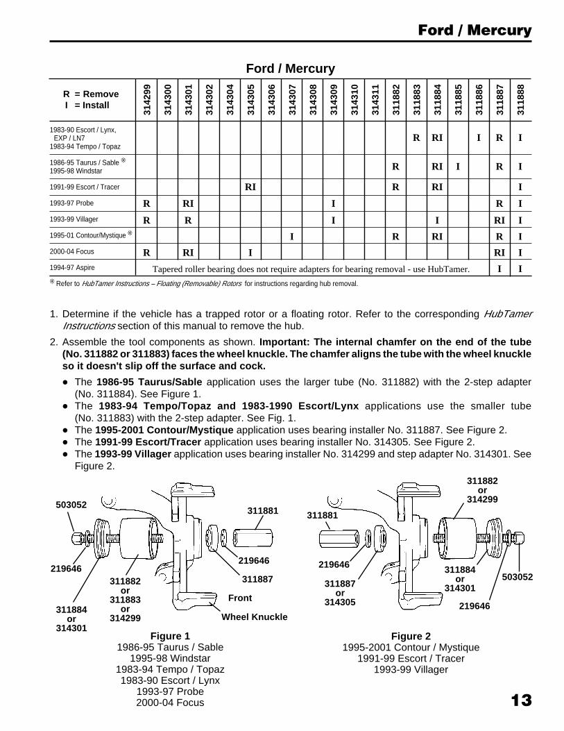
1983-90 Escort / Lynx,EXP / LN7
1983-94 Tempo / Topaz
1986-95 Taurus / Sable j
1995-98 Windstar
1991-99 Escort / Tracer
1993-97 Probe
1993-99 Villager
1995-01 Contour/Mystique j
2000-04 Focus
1994-97 Aspire
j Refer to HubTamer Instructions – Floating (Removable) Rotors for instructions regarding hub removal.
R RI I R I
R RI I R I
RI R RI I
R RI I R I
R R I I RI I
I R RI R I
R RI I RI I
Tapered roller bearing does not require adapters for bearing removal - use HubTamer. I I
R = RemoveI = Install
Ford / Mercury
Ford / Mercury
1. Determine if the vehicle has a trapped rotor or a floating rotor. Refer to the corresponding HubTamerInstructions section of this manual to remove the hub.
2. Assemble the tool components as shown. Important: The internal chamfer on the end of the tube(No. 311882 or 311883) faces the wheel knuckle. The chamfer aligns the tube with the wheel knuckleso it doesn't slip off the surface and cock.
• The 1986-95 Taurus/Sable application uses the larger tube (No. 311882) with the 2-step adapter(No. 311884). See Figure 1.
• The 1983-94 Tempo/Topaz and 1983-1990 Escort/Lynx applications use the smaller tube(No. 311883) with the 2-step adapter. See Fig. 1.
• The 1995-2001 Contour/Mystique application uses bearing installer No. 311887. See Figure 2.• The 1991-99 Escort/Tracer application uses bearing installer No. 314305. See Figure 2.• The 1993-99 Villager application uses bearing installer No. 314299 and step adapter No. 314301. See
Figure 2.
503052
219646
311884or
314301
311882or
311883or
314299
311881
219646
311887
Figure 11986-95 Taurus / Sable
1995-98 Windstar1983-94 Tempo / Topaz1983-90 Escort / Lynx
1993-97 Probe2000-04 Focus
Front
Wheel Knuckle
Figure 21995-2001 Contour / Mystique
1991-99 Escort / Tracer1993-99 Villager
311887or
314305
219646
311882or
314299
311884or
314301
311881
219646
503052
14
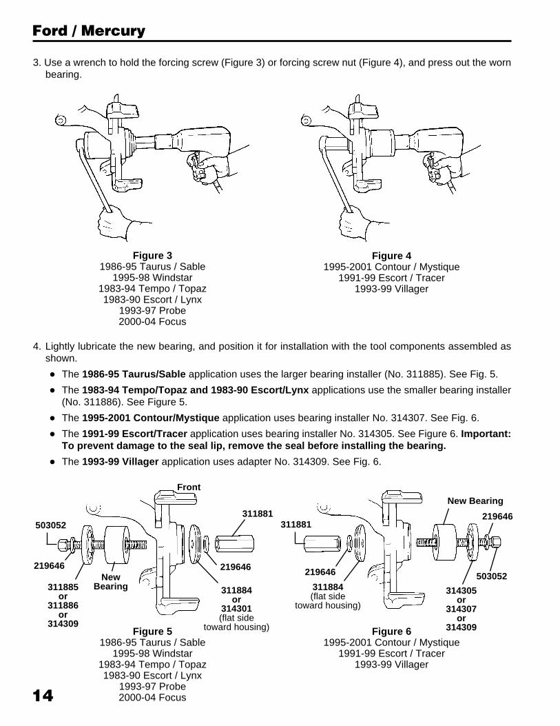
3. Use a wrench to hold the forcing screw (Figure 3) or forcing screw nut (Figure 4), and press out the wornbearing.
Ford / Mercury
Figure 31986-95 Taurus / Sable
1995-98 Windstar1983-94 Tempo / Topaz1983-90 Escort / Lynx
1993-97 Probe2000-04 Focus
Figure 41995-2001 Contour / Mystique
1991-99 Escort / Tracer1993-99 Villager
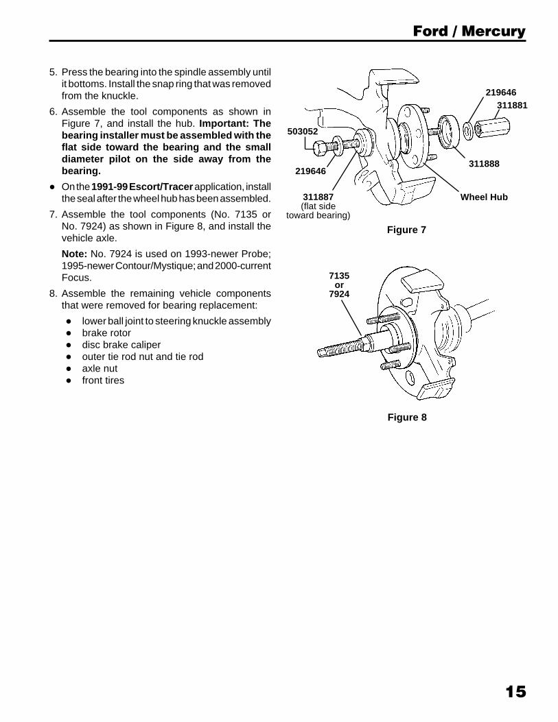
4. Lightly lubricate the new bearing, and position it for installation with the tool components assembled asshown.
• The 1986-95 Taurus/Sable application uses the larger bearing installer (No. 311885). See Fig. 5.
• The 1983-94 Tempo/Topaz and 1983-90 Escort/Lynx applications use the smaller bearing installer(No. 311886). See Figure 5.
• The 1995-2001 Contour/Mystique application uses bearing installer No. 314307. See Fig. 6.
• The 1991-99 Escort/Tracer application uses bearing installer No. 314305. See Figure 6. Important:To prevent damage to the seal lip, remove the seal before installing the bearing.
• The 1993-99 Villager application uses adapter No. 314309. See Fig. 6.
219646
311885or
311886or
314309
NewBearing
311881
219646
Figure 51986-95 Taurus / Sable
1995-98 Windstar1983-94 Tempo / Topaz1983-90 Escort / Lynx
1993-97 Probe2000-04 Focus
503052
Front
311884or
314301(flat side
toward housing)
219646
219646
New Bearing
314305or
314307or
314309
503052
Figure 61995-2001 Contour / Mystique
1991-99 Escort / Tracer1993-99 Villager
311881
311884(flat side
toward housing)
15
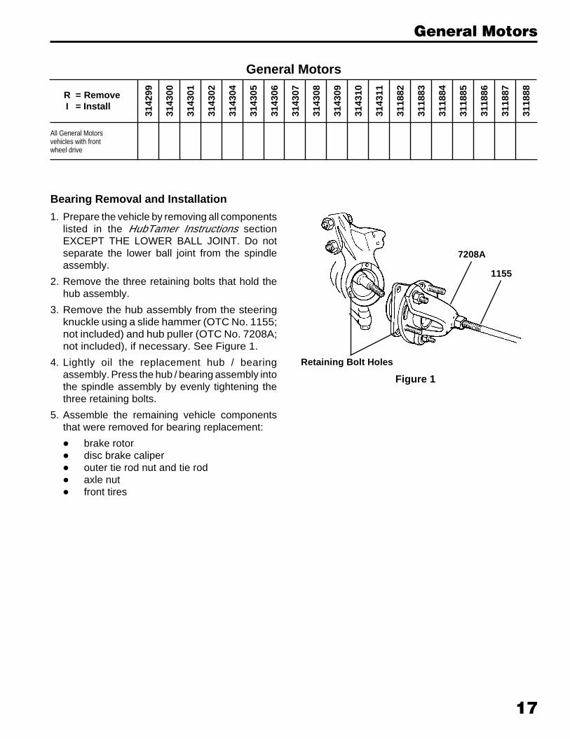
5. Press the bearing into the spindle assembly untilit bottoms. Install the snap ring that was removedfrom the knuckle.
6. Assemble the tool components as shown inFigure 7, and install the hub. Important: Thebearing installer must be assembled with theflat side toward the bearing and the smalldiameter pilot on the side away from thebearing.
• On the 1991-99 Escort/Tracer application, installthe seal after the wheel hub has been assembled.
7. Assemble the tool components (No. 7135 orNo. 7924) as shown in Figure 8, and install thevehicle axle.
Note: No. 7924 is used on 1993-newer Probe;1995-newer Contour/Mystique; and 2000-currentFocus.
8. Assemble the remaining vehicle componentsthat were removed for bearing replacement:
• lower ball joint to steering knuckle assembly• brake rotor• disc brake caliper• outer tie rod nut and tie rod• axle nut• front tires
Ford / Mercury
503052
219646
311887(flat side
toward bearing)
219646311881
Wheel Hub
311888
Figure 7
Figure 8
7135or
7924

16
This page has been left blank.
17
3142
99
3143
00
3143
01
3143
02
3143
04
3143
05
3143
06
3143
07
3143
08
3143
09
3143
10
3143
11
3118
82
3118
83
3118
84
3118
85
3118
86
3118
87
3118
88R = RemoveI = Install
All General Motorsvehicles with frontwheel drive
Bearing Removal and Installation
1. Prepare the vehicle by removing all componentslisted in the HubTamer Instructions sectionEXCEPT THE LOWER BALL JOINT. Do notseparate the lower ball joint from the spindleassembly.
2. Remove the three retaining bolts that hold thehub assembly.
3. Remove the hub assembly from the steeringknuckle using a slide hammer (OTC No. 1155;not included) and hub puller (OTC No. 7208A;not included), if necessary. See Figure 1.
4. Lightly oil the replacement hub / bearingassembly. Press the hub / bearing assembly intothe spindle assembly by evenly tightening thethree retaining bolts.
5. Assemble the remaining vehicle componentsthat were removed for bearing replacement:
• brake rotor• disc brake caliper• outer tie rod nut and tie rod• axle nut• front tires
Retaining Bolt Holes
1155
7208A
Figure 1
General Motors
General Motors

18
This page has been left blank.

19
Saturn
3142
99
3143
00
3143
01
3143
02
3143
04
3143
05
3143
06
3143
07
3143
08
3143
09
3143
10
3143
11
3118
82
3118
83
3118
84
3118
85
3118
86
3118
87
3118
88R = RemoveI = Install
R RI I RI I1991-99 SC, SC1, SC2, SL,SL1, SL2, SW1, SW2
Saturn
1. Determine if the vehicle has a trapped rotor or a floating rotor. Refer to the corresponding HubTamerInstructions section of this manual to remove the hub.
2. Assemble the tool components as shown in Figure 1. Hold the forcing screw with a wrench, and press theworn bearing out as shown in Figure 2.
503052
219646
311884
311882
311881
219646
311887
Figure 1
Figure 2
20
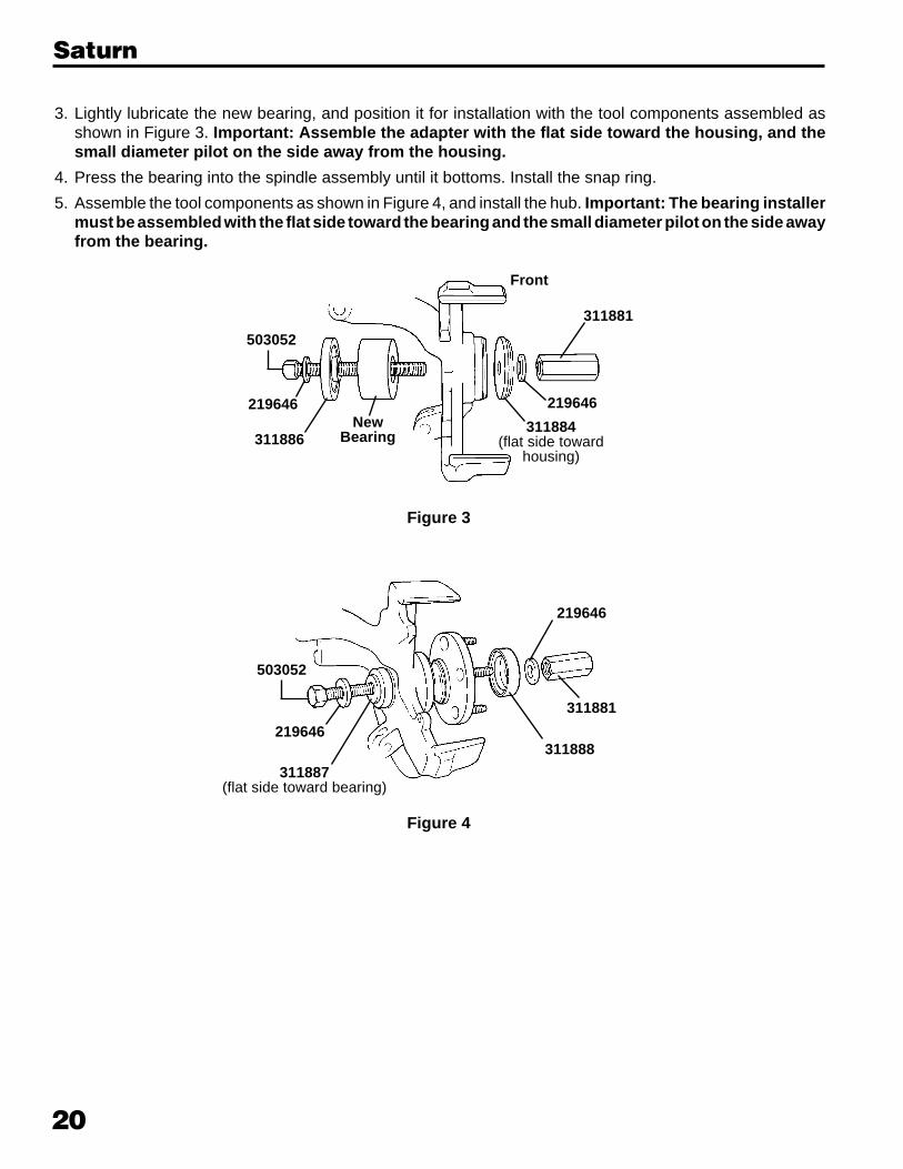
3. Lightly lubricate the new bearing, and position it for installation with the tool components assembled asshown in Figure 3. Important: Assemble the adapter with the flat side toward the housing, and thesmall diameter pilot on the side away from the housing.
4. Press the bearing into the spindle assembly until it bottoms. Install the snap ring.
5. Assemble the tool components as shown in Figure 4, and install the hub. Important: The bearing installermust be assembled with the flat side toward the bearing and the small diameter pilot on the side awayfrom the bearing.
311886New
Bearing
219646
503052
219646
503052
219646311888
219646
311881
311887(flat side toward bearing)
311881
311884(flat side toward
housing)
Front
Figure 3
Figure 4
Saturn

Section 3: Vehicle Specific Operating Instructions - Import
Front Wheel Drive Service Tool Set
No. 6537
Patent No. 6,357,097
Table of ContentsSection 1
Parts List . . . . . . . . . . . . . . . . . . . . . . . . . . . . . . . . . . . . . . . 1
Safety Precautions . . . . . . . . . . . . . . . . . . . . . . . . . . . . . . . 2
HubTamer Instructions—Floating (Removable) Rotors . . . 3
HubTamer Instructions—Trapped Rotors . . . . . . . . . . . . . . 7
Section 2 – Domestic Vehicles
Chrysler / Plymouth / Dodge . . . . . . . . . . . . . . . . . . . . . . . 11
Ford / Mercury . . . . . . . . . . . . . . . . . . . . . . . . . . . . . . . . . 13
General Motors . . . . . . . . . . . . . . . . . . . . . . . . . . . . . . . . . 17
Saturn . . . . . . . . . . . . . . . . . . . . . . . . . . . . . . . . . . . . . . . . 19
Section 3 – Import Vehicles
Acura . . . . . . . . . . . . . . . . . . . . . . . . . . . . . . . . . . . . . . . . 21
Audi . . . . . . . . . . . . . . . . . . . . . . . . . . . . . . . . . . . . . . . . . . 23
Eagle . . . . . . . . . . . . . . . . . . . . . . . . . . . . . . . . . . . . . . . . . 25
Geo . . . . . . . . . . . . . . . . . . . . . . . . . . . . . . . . . . . . . . . . . . 27
Honda . . . . . . . . . . . . . . . . . . . . . . . . . . . . . . . . . . . . . . . . 29
Hyundai . . . . . . . . . . . . . . . . . . . . . . . . . . . . . . . . . . . . . . . 31
Infiniti . . . . . . . . . . . . . . . . . . . . . . . . . . . . . . . . . . . . . . . . 33
Lexus . . . . . . . . . . . . . . . . . . . . . . . . . . . . . . . . . . . . . . . . 35
Mazda . . . . . . . . . . . . . . . . . . . . . . . . . . . . . . . . . . . . . . . . 37
Mitsubishi . . . . . . . . . . . . . . . . . . . . . . . . . . . . . . . . . . . . . 39
Nissan . . . . . . . . . . . . . . . . . . . . . . . . . . . . . . . . . . . . . . . . 41
Subaru . . . . . . . . . . . . . . . . . . . . . . . . . . . . . . . . . . . . . . . 43
Toyota . . . . . . . . . . . . . . . . . . . . . . . . . . . . . . . . . . . . . . . . 45
Volkswagen . . . . . . . . . . . . . . . . . . . . . . . . . . . . . . . . . . . . 47
Warranty Information . . . . . . . . . . . . . . . . Inside Back Cover
21
Acura
3142
99
3143
00
3143
01
3143
02
3143
04
3143
05
3143
06
3143
07
3143
08
3143
09
3143
10
3143
11
3118
82
3118
83
3118
84
3118
85
3118
86
3118
87
3118
88R = RemoveI = Install
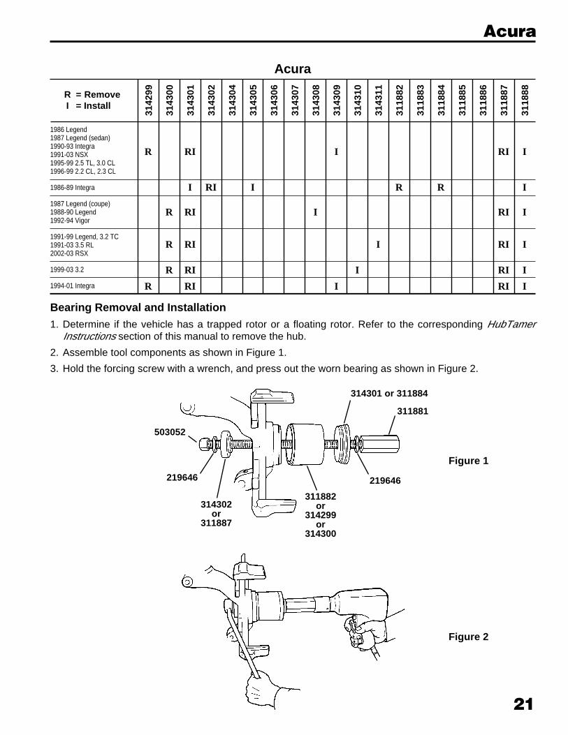
1986 Legend1987 Legend (sedan)1990-93 Integra1991-03 NSX1995-99 2.5 TL, 3.0 CL1996-99 2.2 CL, 2.3 CL
1986-89 Integra
1987 Legend (coupe)1988-90 Legend1992-94 Vigor
1991-99 Legend, 3.2 TC1991-03 3.5 RL2002-03 RSX
1999-03 3.2
1994-01 Integra
R RI I RI I
I RI I R R I
R RI I RI I
R RI I RI I
R RI I RI I
R RI I RI I
Acura
Bearing Removal and Installation1. Determine if the vehicle has a trapped rotor or a floating rotor. Refer to the corresponding HubTamer
Instructions section of this manual to remove the hub.
2. Assemble tool components as shown in Figure 1.
3. Hold the forcing screw with a wrench, and press out the worn bearing as shown in Figure 2.
Figure 2
314301 or 311884
311881
311882or
314299or
314300
503052
219646
314302or
311887
219646
Figure 1
22
Acura
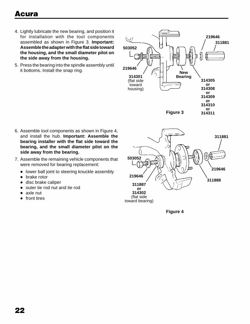
6. Assemble tool components as shown in Figure 4,and install the hub. Important: Assemble thebearing installer with the flat side toward thebearing, and the small diameter pilot on theside away from the bearing.
7. Assemble the remaining vehicle components thatwere removed for bearing replacement:
• lower ball joint to steering knuckle assembly• brake rotor• disc brake caliper• outer tie rod nut and tie rod• axle nut• front tires
311881
503052
219646311888
219646
311887or
314302(flat side
toward bearing)
Figure 4
4. Lightly lubricate the new bearing, and position itfor installation with the tool componentsassembled as shown in Figure 3. Important:Assemble the adapter with the flat side towardthe housing, and the small diameter pilot onthe side away from the housing.
5. Press the bearing into the spindle assembly untilit bottoms. Install the snap ring.
Figure 3
503052
219646
314301(flat sidetoward
housing)
NewBearing
314305or
314308or
314309or
314310or
314311
311881219646
23
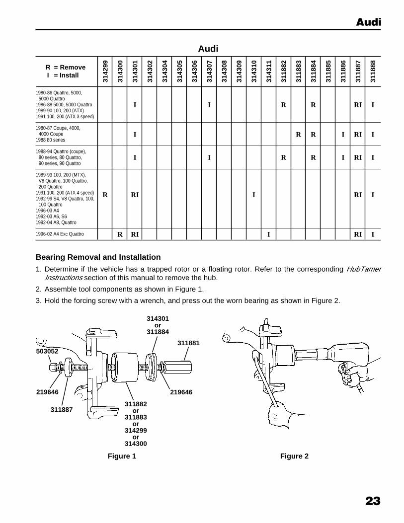
1980-86 Quattro, 5000,5000 Quattro
1986-88 5000, 5000 Quattro1989-90 100, 200 (ATX)1991 100, 200 (ATX 3 speed)
1980-87 Coupe, 4000,4000 Coupe
1988 80 series
1988-94 Quattro (coupe),80 series, 80 Quattro,90 series, 90 Quattro
1989-93 100, 200 (MTX),V8 Quattro, 100 Quattro,200 Quattro
1991 100, 200 (ATX 4 speed)1992-99 S4, V8 Quattro, 100,
100 Quattro1996-03 A41992-03 A6, S61992-04 A8, Quattro
1996-02 A4 Exc Quattro
I I R R RI I
I R R I RI I
I I R R I RI I
R RI I RI I
R RI I RI I
3142
99
3143
00
3143
01
3143
02
3143
04
3143
05
3143
06
3143
07
3143
08
3143
09
3143
10
3143
11
3118
82
3118
83
3118
84
3118
85
3118
86
3118
87
3118
88R = RemoveI = Install
Audi
314301or
311884
311881
311882or
311883or
314299or
314300
503052
219646
311887
Figure 1
Bearing Removal and Installation1. Determine if the vehicle has a trapped rotor or a floating rotor. Refer to the corresponding HubTamer
Instructions section of this manual to remove the hub.
2. Assemble tool components as shown in Figure 1.
3. Hold the forcing screw with a wrench, and press out the worn bearing as shown in Figure 2.
219646
Figure 2
Audi
24
Audi
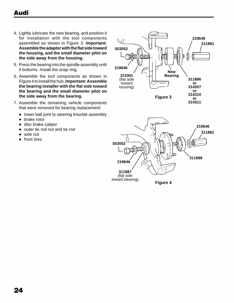
4. Lightly lubricate the new bearing, and position itfor installation with the tool componentsassembled as shown in Figure 3. Important:Assemble the adapter with the flat side towardthe housing, and the small diameter pilot onthe side away from the housing.
5. Press the bearing into the spindle assembly untilit bottoms. Install the snap ring.
6. Assemble the tool components as shown inFigure 4 to install the hub. Important: Assemblethe bearing installer with the flat side towardthe bearing and the small diameter pilot onthe side away from the bearing.
7. Assemble the remaining vehicle componentsthat were removed for bearing replacement:
• lower ball joint to steering knuckle assembly• brake rotor• disc brake caliper• outer tie rod nut and tie rod• axle nut• front tires
503052
219646
314301(flat sidetoward
housing)
NewBearing
311886or
314307or
314310or
314311
311881219646
Figure 3
219646
219646
311881
503052
311887(flat side
toward bearing)
311888
Figure 4
25
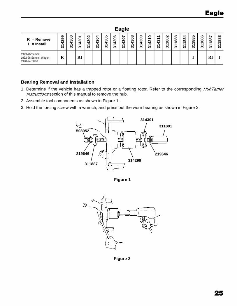
1993-96 Summit1992-96 Summit Wagon1990-94 Talon
3142
99
3143
00
3143
01
3143
02
3143
04
3143
05
3143
06
3143
07
3143
08
3143
09
3143
10
3143
11
3118
82
3118
83
3118
84
3118
85
3118
86
3118
87
3118
88R = RemoveI = Install
Eagle
R RI I RI I
Eagle
Bearing Removal and Installation1. Determine if the vehicle has a trapped rotor or a floating rotor. Refer to the corresponding HubTamer
Instructions section of this manual to remove the hub.
2. Assemble tool components as shown in Figure 1.
3. Hold the forcing screw with a wrench, and press out the worn bearing as shown in Figure 2.
311881
314299
503052
219646
311887
219646
314301
Figure 1
Figure 2

26
Eagle
4. Lightly lubricate the new bearing, and position it for installation with the tool components assembled as shownin Figure 3. Important: Assemble the adapter with the flat side toward the housing, and the smalldiameter pilot on the side away from the housing.
5. Press the bearing into the spindle assembly until it bottoms. Install the snap ring.
6. Assemble tool components as shown in Figure 4, and install the hub. Important: Assemble the bearinginstaller with the flat side toward the bearing, and the small diameter pilot on the side away from thebearing.
503052
219646
314301(flat sidetoward
housing)
NewBearing
311881
219646
311885
311881
503052
219646311888
219646
311887(flat side
toward bearing)
Figure 3
Figure 4
27
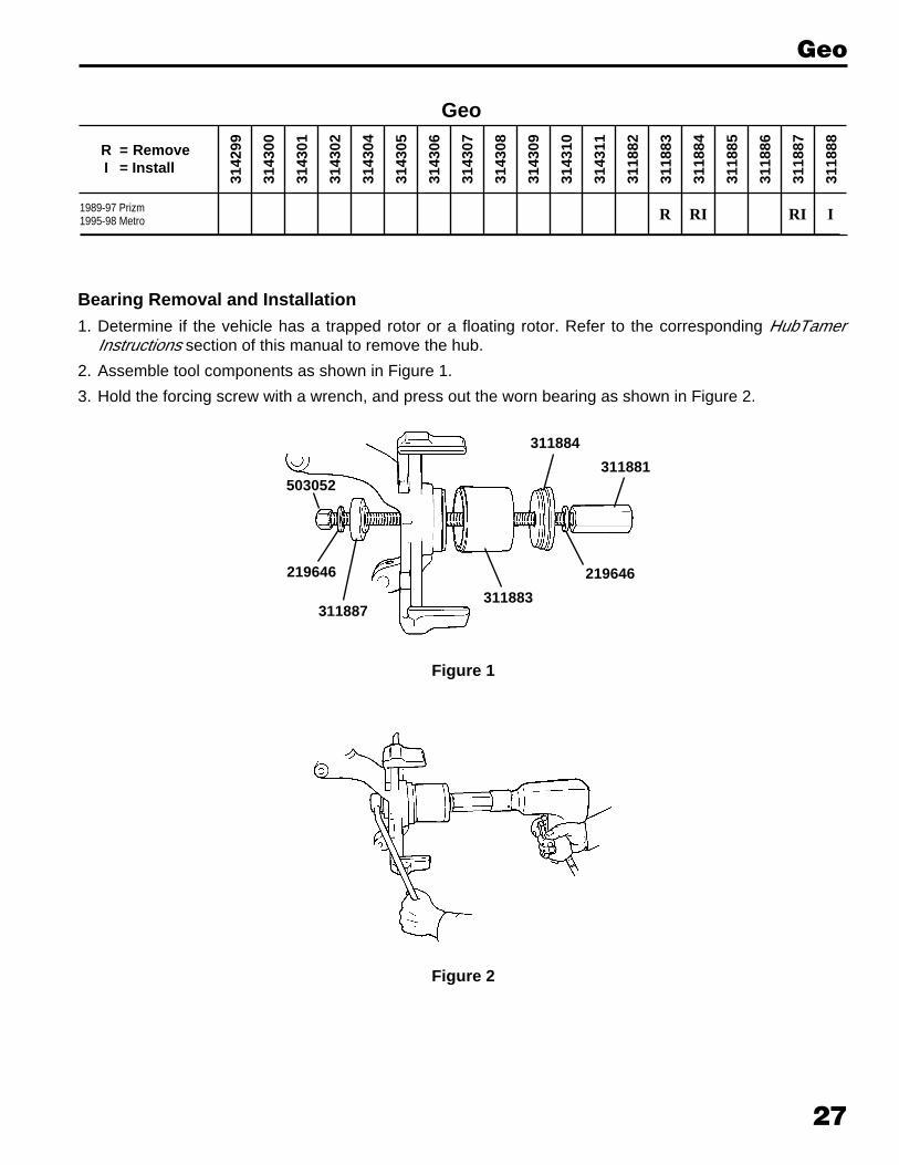
1989-97 Prizm1995-98 Metro
3142
99
3143
00
3143
01
3143
02
3143
04
3143
05
3143
06
3143
07
3143
08
3143
09
3143
10
3143
11
3118
82
3118
83
3118
84
3118
85
3118
86
3118
87
3118
88R = RemoveI = Install
Geo
R RI RI I
Geo
Bearing Removal and Installation1. Determine if the vehicle has a trapped rotor or a floating rotor. Refer to the corresponding HubTamer
Instructions section of this manual to remove the hub.
2. Assemble tool components as shown in Figure 1.
3. Hold the forcing screw with a wrench, and press out the worn bearing as shown in Figure 2.
311881
311883
503052
219646
311887
219646
311884
Figure 1
Figure 2

28
Geo
4. Lightly lubricate the new bearing, and position it for installation with the tool components assembled as shownin Figure 3. Important: Assemble the adapter with the flat side toward the housing, and the smalldiameter pilot on the side away from the housing.
5. Press the bearing into the spindle assembly until it bottoms. Install the snap ring.
6. Assemble tool components as shown in Figure 4, and install the hub. Important: Assemble the bearinginstaller with the flat side toward the bearing, and the small diameter pilot on the side away from thebearing.
503052
219646
311884(flat sidetoward
housing)
NewBearing
311881
219646
311887
311881
503052
219646311888
219646
311887(flat side
toward bearing)
Figure 3
Figure 4
29
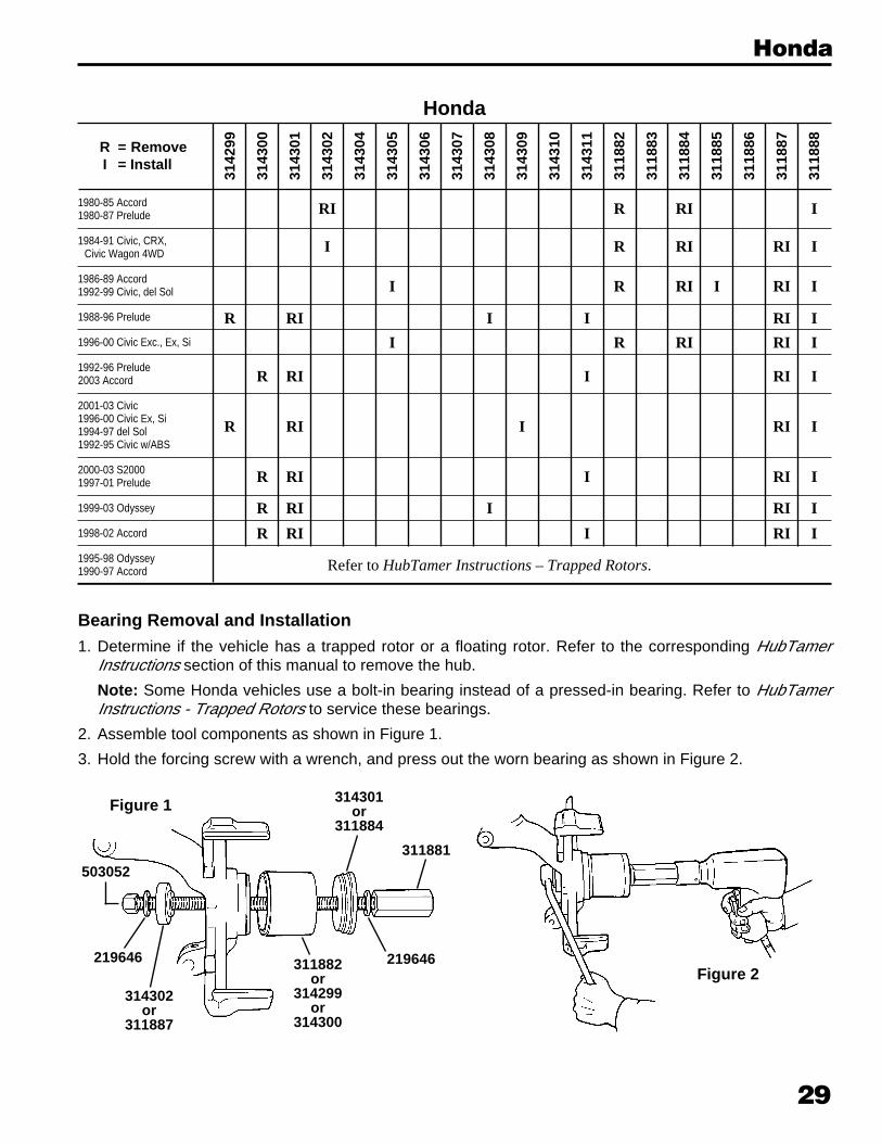
1980-85 Accord1980-87 Prelude
1984-91 Civic, CRX,Civic Wagon 4WD
1986-89 Accord1992-99 Civic, del Sol
1988-96 Prelude
1996-00 Civic Exc., Ex, Si
1992-96 Prelude2003 Accord
2001-03 Civic1996-00 Civic Ex, Si1994-97 del Sol1992-95 Civic w/ABS
2000-03 S20001997-01 Prelude
1999-03 Odyssey
1998-02 Accord
1995-98 Odyssey1990-97 Accord
3142
99
3143
00
3143
01
3143
02
3143
04
3143
05
3143
06
3143
07
3143
08
3143
09
3143
10
3143
11
3118
82
3118
83
3118
84
3118
85
3118
86
3118
87
3118
88R = RemoveI = Install
Honda
RI R RI I
I R RI RI I
I R RI I RI I
R RI I I RI I
I R RI RI I
R RI I RI I
R RI I RI I
R RI I RI I
R RI I RI I
R RI I RI I
Refer to HubTamer Instructions – Trapped Rotors.
Bearing Removal and Installation1. Determine if the vehicle has a trapped rotor or a floating rotor. Refer to the corresponding HubTamer
Instructions section of this manual to remove the hub.
Note: Some Honda vehicles use a bolt-in bearing instead of a pressed-in bearing. Refer to HubTamerInstructions - Trapped Rotors to service these bearings.
2. Assemble tool components as shown in Figure 1.
3. Hold the forcing screw with a wrench, and press out the worn bearing as shown in Figure 2.
Figure 2
Figure 1
Honda
314301or
311884
311881
219646
314302or
311887
219646
503052
311882or
314299or
314300
30
Honda
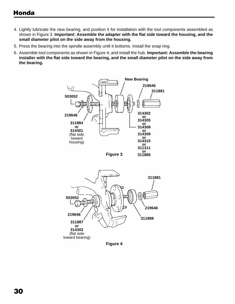
4. Lightly lubricate the new bearing, and position it for installation with the tool components assembled asshown in Figure 3. Important: Assemble the adapter with the flat side toward the housing, and thesmall diameter pilot on the side away from the housing.
5. Press the bearing into the spindle assembly until it bottoms. Install the snap ring.
6. Assemble tool components as shown in Figure 4, and install the hub. Important: Assemble the bearinginstaller with the flat side toward the bearing, and the small diameter pilot on the side away fromthe bearing.
219646
311884or
314301(flat sidetoward
housing)
311881219646
New Bearing
503052
314302or
314305or
314308or
314309or
314310or
311311or
311885Figure 3
311881
503052
219646
311887or
314302(flat side
toward bearing)
311888
219646
Figure 4

31
3142
99
3143
00
3143
01
3143
02
3143
04
3143
05
3143
06
3143
07
3143
08
3143
09
3143
10
3143
11
3118
82
3118
83
3118
84
3118
85
3118
86
3118
87
3118
88R = RemoveI = Install
Hyundai
1986-95 Elantra, Scoupe1995-1999 Accent
1989-94 Sonata
2001-02 Santa Fe
1999-02 Sonata
2000-02 Accent1996-02 Elantra1997-01 Triburon
I R RI RI I
R RI I RI I
R RI I RI I
R RI I RI I
R RI I RI I
Hyundai
Bearing Removal and Installation1. Determine if the vehicle has a trapped rotor or a floating rotor. Refer to the corresponding HubTamer
Instructions section of this manual to remove the hub.
2. Assemble tool components as shown in Figure 1.
3. Hold the forcing screw with a wrench, and press out the worn bearing as shown in Figure 2.
311881
311882or
314299or
314300
503052
219646
311887
219646
311884or
314301
Figure 1
Figure 2
32
Hyundai
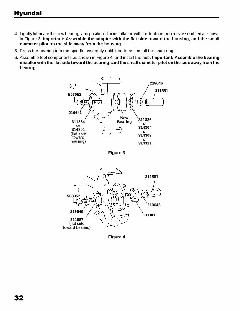
4. Lightly lubricate the new bearing, and position it for installation with the tool components assembled as shownin Figure 3. Important: Assemble the adapter with the flat side toward the housing, and the smalldiameter pilot on the side away from the housing.
5. Press the bearing into the spindle assembly until it bottoms. Install the snap ring.
6. Assemble tool components as shown in Figure 4, and install the hub. Important: Assemble the bearinginstaller with the flat side toward the bearing, and the small diameter pilot on the side away from thebearing.
503052
219646
311884or
314301(flat sidetoward
housing)
NewBearing
311881
219646
311886or
314304or
314309or
314311
311881
503052
219646311888
219646
311887(flat side
toward bearing)
Figure 3
Figure 4

33
1991-02 G2O1996-01 I30
3142
99
3143
00
3143
01
3143
02
3143
04
3143
05
3143
06
3143
07
3143
08
3143
09
3143
10
3143
11
3118
82
3118
83
3118
84
3118
85
3118
86
3118
87
3118
88R = RemoveI = Install
Infiniti
I R RI RI I
Infiniti
Bearing Removal and Installation1. Determine if the vehicle has a trapped rotor or a floating rotor. Refer to the corresponding HubTamer
Instructions section of this manual to remove the hub.
2. Assemble tool components as shown in Figure 1.
3. Hold the forcing screw with a wrench, and press out the worn bearing as shown in Figure 2.
311881
311882
503052
219646
311887
219646
311884
Figure 1
Figure 2
34
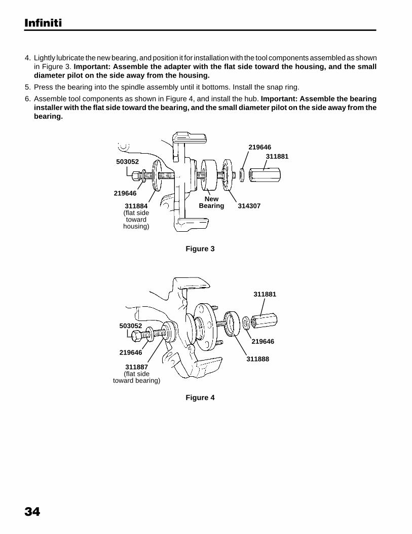
4. Lightly lubricate the new bearing, and position it for installation with the tool components assembled as shownin Figure 3. Important: Assemble the adapter with the flat side toward the housing, and the smalldiameter pilot on the side away from the housing.
5. Press the bearing into the spindle assembly until it bottoms. Install the snap ring.
6. Assemble tool components as shown in Figure 4, and install the hub. Important: Assemble the bearinginstaller with the flat side toward the bearing, and the small diameter pilot on the side away from thebearing.
503052
219646
311884(flat sidetoward
housing)
NewBearing
311881219646
314307
311881
503052
219646311888
219646
311887(flat side
toward bearing)
Figure 3
Figure 4
Infiniti
35
3142
99
3143
00
3143
01
3143
02
3143
04
3143
05
3143
06
3143
07
3143
08
3143
09
3143
10
3143
11
3118
82
3118
83
3118
84
3118
85
3118
86
3118
87
3118
88R = RemoveI = Install
Lexus
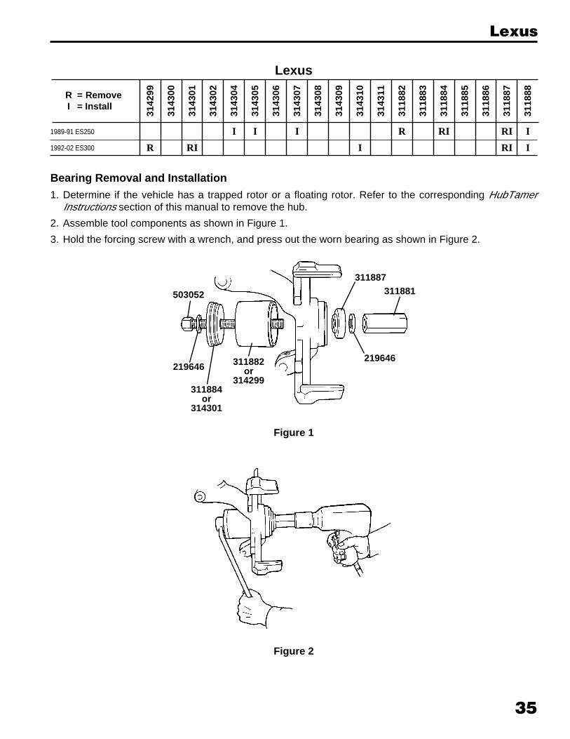
1989-91 ES250
1992-02 ES300
I I I R RI RI I
R RI I RI I
Bearing Removal and Installation1. Determine if the vehicle has a trapped rotor or a floating rotor. Refer to the corresponding HubTamer
Instructions section of this manual to remove the hub.
2. Assemble tool components as shown in Figure 1.
3. Hold the forcing screw with a wrench, and press out the worn bearing as shown in Figure 2.
503052
219646
311884or
314301
311882or
314299
311887
219646
311881
Lexus
Figure 1
Figure 2
36
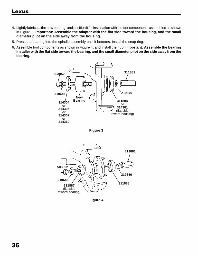
4. Lightly lubricate the new bearing, and position it for installation with the tool components assembled as shownin Figure 3. Important: Assemble the adapter with the flat side toward the housing, and the smalldiameter pilot on the side away from the housing.
5. Press the bearing into the spindle assembly until it bottoms. Install the snap ring.
6. Assemble tool components as shown in Figure 4, and install the hub. Important: Assemble the bearinginstaller with the flat side toward the bearing, and the small diameter pilot on the side away from thebearing.
311881
503052
219646311888
219646
503052
NewBearing 311884
or314301(flat side
toward housing)
219646
311881
219646
314304or
314305or
314307or
314310
311887(flat side
toward bearing)
Figure 3
Figure 4
Lexus
37
3142
99
3143
00
3143
01
3143
02
3143
04
3143
05
3143
06
3143
07
3143
08
3143
09
3143
10
3143
11
3118
82
3118
83
3118
84
3118
85
3118
86
3118
87
3118
88R = RemoveI = Install
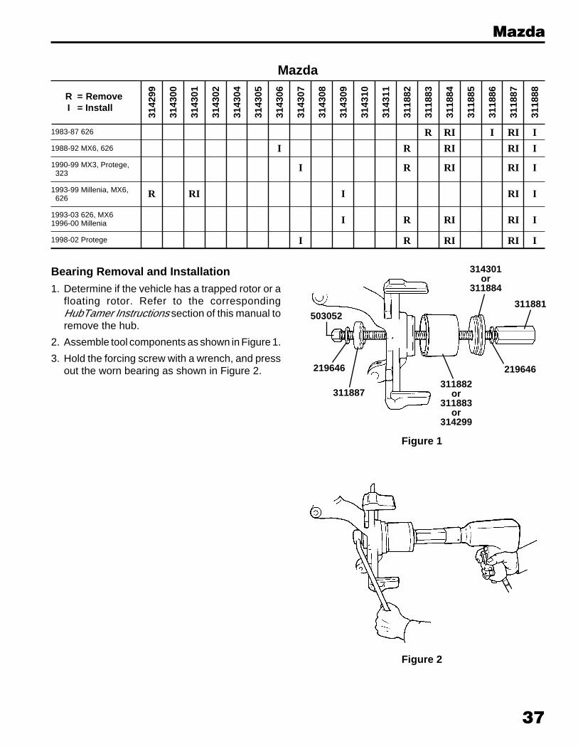
Mazda
1983-87 626
1988-92 MX6, 626
1990-99 MX3, Protege,323
1993-99 Millenia, MX6,626
1993-03 626, MX61996-00 Millenia
1998-02 Protege
R RI I RI I
I R RI RI I
I R RI RI I
R RI I RI I
I R RI RI I
I R RI RI I
Bearing Removal and Installation1. Determine if the vehicle has a trapped rotor or a
floating rotor. Refer to the correspondingHubTamer Instructions section of this manual toremove the hub.
2. Assemble tool components as shown in Figure 1.
3. Hold the forcing screw with a wrench, and pressout the worn bearing as shown in Figure 2.
Figure 2
Figure 1
314301or
311884
311881
311882or
311883or
314299
219646
311887
219646
503052
Mazda
38
Mazda
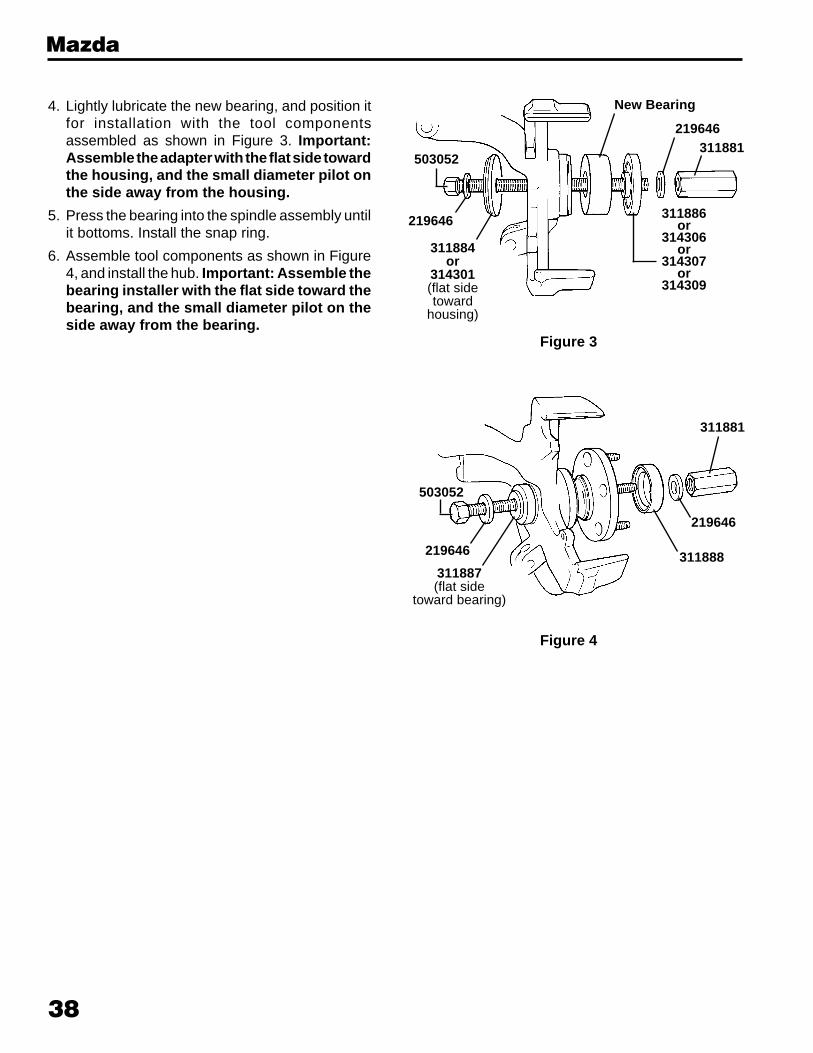
4. Lightly lubricate the new bearing, and position itfor installation with the tool componentsassembled as shown in Figure 3. Important:Assemble the adapter with the flat side towardthe housing, and the small diameter pilot onthe side away from the housing.
5. Press the bearing into the spindle assembly untilit bottoms. Install the snap ring.
6. Assemble tool components as shown in Figure4, and install the hub. Important: Assemble thebearing installer with the flat side toward thebearing, and the small diameter pilot on theside away from the bearing.
219646
311884or
314301(flat sidetoward
housing)
311881219646
New Bearing
503052
311886or
314306or
314307or
314309
Figure 3
311881
503052
219646
311887(flat side
toward bearing)
311888
219646
Figure 4

39
1990-03 Diamante1992-02 Mirage1989-94 Eclipse1985-93 Galant, Sigma1999 3000GT
3142
99
3143
00
3143
01
3143
02
3143
04
3143
05
3143
06
3143
07
3143
08
3143
09
3143
10
3143
11
3118
82
3118
83
3118
84
3118
85
3118
86
3118
87
3118
88R = RemoveI = Install
Mitsubishi
R RI I RI I
Mitsubishi
Bearing Removal and Installation1. Determine if the vehicle has a trapped rotor or a floating rotor. Refer to the corresponding HubTamer
Instructions section of this manual to remove the hub.
2. Assemble tool components as shown in Figure 1.
3. Hold the forcing screw with a wrench, and press out the worn bearing as shown in Figure 2.
Figure 1
Figure 2
503052
219646
314301
314300
311887
219646
311881
40
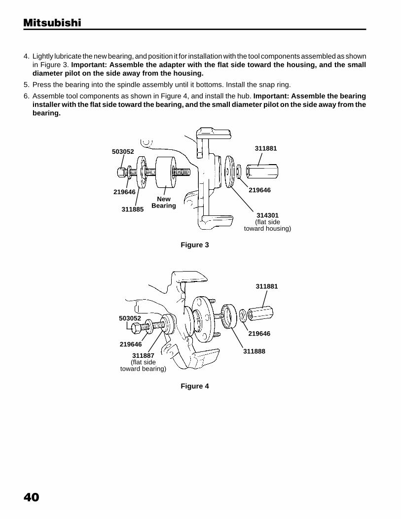
4. Lightly lubricate the new bearing, and position it for installation with the tool components assembled as shownin Figure 3. Important: Assemble the adapter with the flat side toward the housing, and the smalldiameter pilot on the side away from the housing.
5. Press the bearing into the spindle assembly until it bottoms. Install the snap ring.
6. Assemble tool components as shown in Figure 4, and install the hub. Important: Assemble the bearinginstaller with the flat side toward the bearing, and the small diameter pilot on the side away from thebearing.
Figure 3
Figure 4
Mitsubishi
311881
503052
219646311888
219646
503052
NewBearing
314301(flat side
toward housing)
219646
311881
219646
311885
311887(flat side
toward bearing)

41
1987-90 Pulsar, Sentra1991-99 NX, Sentra, 200 SX
1989 Maxima1990-99 Altima, Maxima,
Stanza2000-01 Altima2000-03 Sentra
1985-88 Maxima, MaximaWagon
1985-88 Stanza, StanzaWagon
1989 Stanza
3142
99
3143
00
3143
01
3143
02
3143
04
3143
05
3143
06
3143
07
3143
08
3143
09
3143
10
3143
11
3118
82
3118
83
3118
84
3118
85
3118
86
3118
87
3118
88R = RemoveI = Install
Nissan
RI I R RI I
I R RI RI I
I R RI RI I
Bearing Removal and Installation1. Determine if the vehicle has a trapped rotor or a
floating rotor. Refer to the corresponding HubTamerInstructions section of this manual to remove thehub.
2. Assemble tool components as shown in Figure 1.
3. Hold the forcing screw with a wrench, and press outthe worn bearing as shown in Figure 2.
311881
311882
503052
219646
311887or
314304
219646
311884
Figure 1
Figure 2
Nissan

42
Nissan
219646
311884(flat sidetoward
housing)
NewBearing
311881219646
314306or
314307
4. Lightly lubricate the new bearing, and position itfor installation with the tool componentsassembled as shown in Figure 3. Important:Assemble the adapter with the flat side towardthe housing, and the small diameter pilot onthe side away from the housing.
5. Press the bearing into the spindle assembly untilit bottoms. Install the snap ring.
6. Assemble tool components as shown in Figure4, and install the hub. Important: Assemble thebearing installer with the flat side toward thebearing, and the small diameter pilot on theside away from the bearing. Figure 3
311881
503052
219646311888
219646
311887or
314304(flat side
toward bearing)Figure 4
503052
43
1994-03 Legacy1993-03 Impreza1992-98 SVX
3142
99
3143
00
3143
01
3143
02
3143
04
3143
05
3143
06
3143
07
3143
08
3143
09
3143
10
3143
11
3118
82
3118
83
3118
84
3118
85
3118
86
3118
87
3118
88R = RemoveI = Install
Subaru
I R RI RI I
Subaru
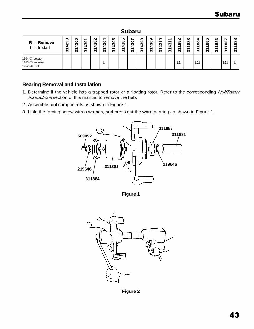
Bearing Removal and Installation1. Determine if the vehicle has a trapped rotor or a floating rotor. Refer to the corresponding HubTamer
Instructions section of this manual to remove the hub.
2. Assemble tool components as shown in Figure 1.
3. Hold the forcing screw with a wrench, and press out the worn bearing as shown in Figure 2.
Figure 1
Figure 2
503052
219646
311884
311882
311887
219646
311881
44
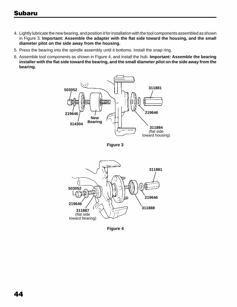
4. Lightly lubricate the new bearing, and position it for installation with the tool components assembled as shownin Figure 3. Important: Assemble the adapter with the flat side toward the housing, and the smalldiameter pilot on the side away from the housing.
5. Press the bearing into the spindle assembly until it bottoms. Install the snap ring.
6. Assemble tool components as shown in Figure 4, and install the hub. Important: Assemble the bearinginstaller with the flat side toward the bearing, and the small diameter pilot on the side away from thebearing.
Figure 3
Figure 4
Subaru
311881
503052
219646311888
219646
503052
NewBearing
311884(flat side
toward housing)
219646
311881
219646
314304
311887(flat side
toward bearing)
45
3142
99
3143
00
3143
01
3143
02
3143
04
3143
05
3143
06
3143
07
3143
08
3143
09
3143
10
3143
11
3118
82
3118
83
3118
84
3118
85
3118
86
3118
87
3118
88R = RemoveI = Install
Toyota
1983-89 Corolla FX1983-91 Camry1983-99 Celica1983-99 Tercel1987-99 Paseo1988-02 Corolla
1992-03 Avalon, Camry
2003 Corolla2001-03 Prius
2000-03 Echo2000 Celica
I I I R RI RI I
R RI I RI I
I R RI RI I
I R RI RI I
Toyota
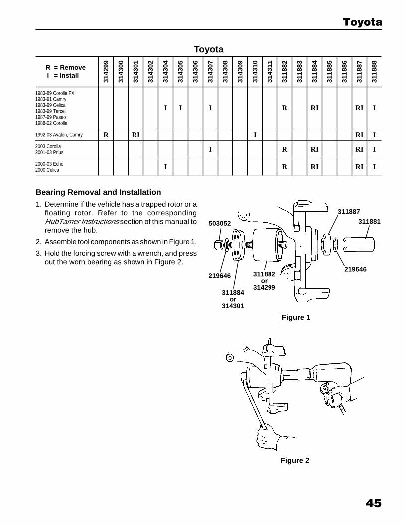
Bearing Removal and Installation1. Determine if the vehicle has a trapped rotor or a
floating rotor. Refer to the correspondingHubTamer Instructions section of this manual toremove the hub.
2. Assemble tool components as shown in Figure 1.
3. Hold the forcing screw with a wrench, and pressout the worn bearing as shown in Figure 2.
219646
311884or
314301
311882or
314299
311887
219646
311881503052
Figure 1
Figure 2
46
Toyota
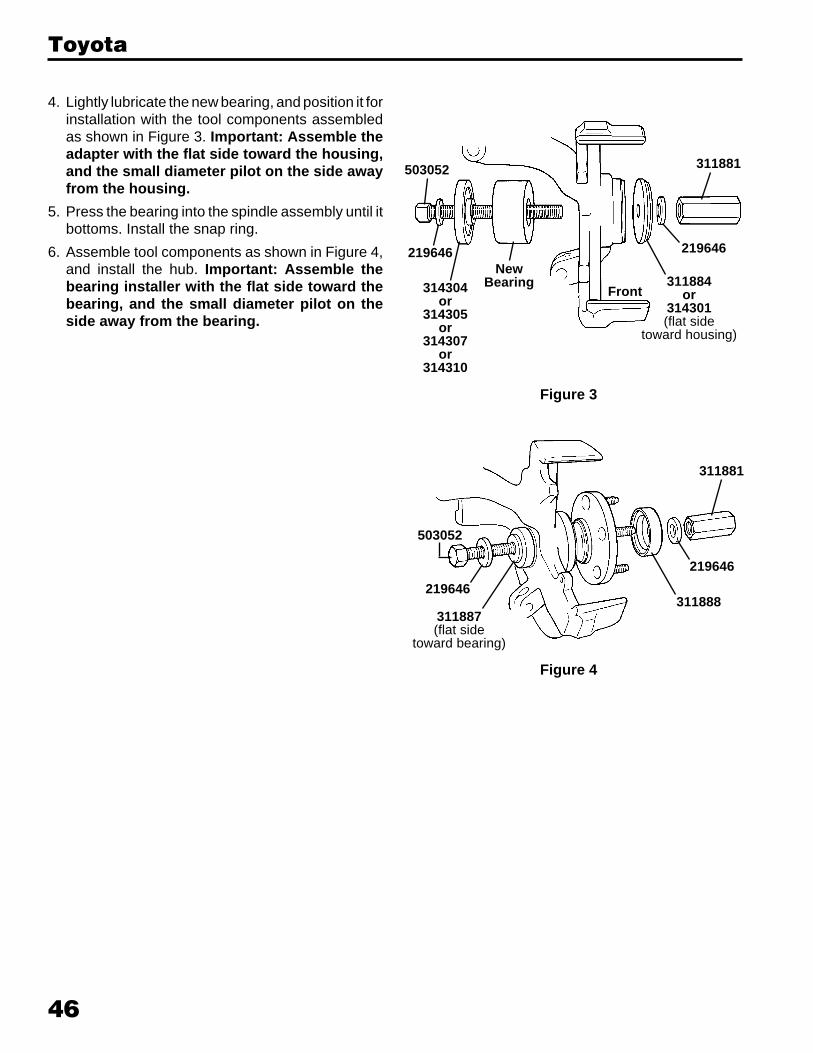
4. Lightly lubricate the new bearing, and position it forinstallation with the tool components assembledas shown in Figure 3. Important: Assemble theadapter with the flat side toward the housing,and the small diameter pilot on the side awayfrom the housing.
5. Press the bearing into the spindle assembly until itbottoms. Install the snap ring.
6. Assemble tool components as shown in Figure 4,and install the hub. Important: Assemble thebearing installer with the flat side toward thebearing, and the small diameter pilot on theside away from the bearing.
NewBearing 311884
or314301(flat side
toward housing)
219646
311881
219646
314304or
314305or
314307or
314310
Front
503052
Figure 3
311881
503052
219646
311887(flat side
toward bearing)
311888
219646
Figure 4

47
1980-84 Jetta, Rabbit1980-96 Scirocco1985-87 Golf, GTI, Jetta1985-96 Cabriolet
1980-96 Dasher, Fox,Quantum, Quantum Sychro
1988-02 Golf, GTI, Jetta1990-99 Corrado, Passat
1998-03 Passat1992-96 Eurovan
Volkswagen
3142
99
3143
00
3143
01
3143
02
3143
04
3143
05
3143
06
3143
07
3143
08
3143
09
3143
10
3143
11
3118
82
3118
83
3118
84
3118
85
3118
86
3118
87
3118
88R = RemoveI = Install
RI R RI I I
I R RI RI I
I R RI RI I
R RI RI I
311882or
311883314302
or311887
219646
311884
311881
219646
503052
Bearing Removal and Installation1. Determine if the vehicle has a trapped rotor or a
floating rotor. Refer to the correspondingHubTamer Instructions section of this manual toremove the hub.
2. Assemble tool components as shown in Figure 1.
3. Hold the forcing screw with a wrench, and pressout the worn bearing as shown in Figure 2.
Figure 1
Figure 2
Volkswagen
48
Volkswagen
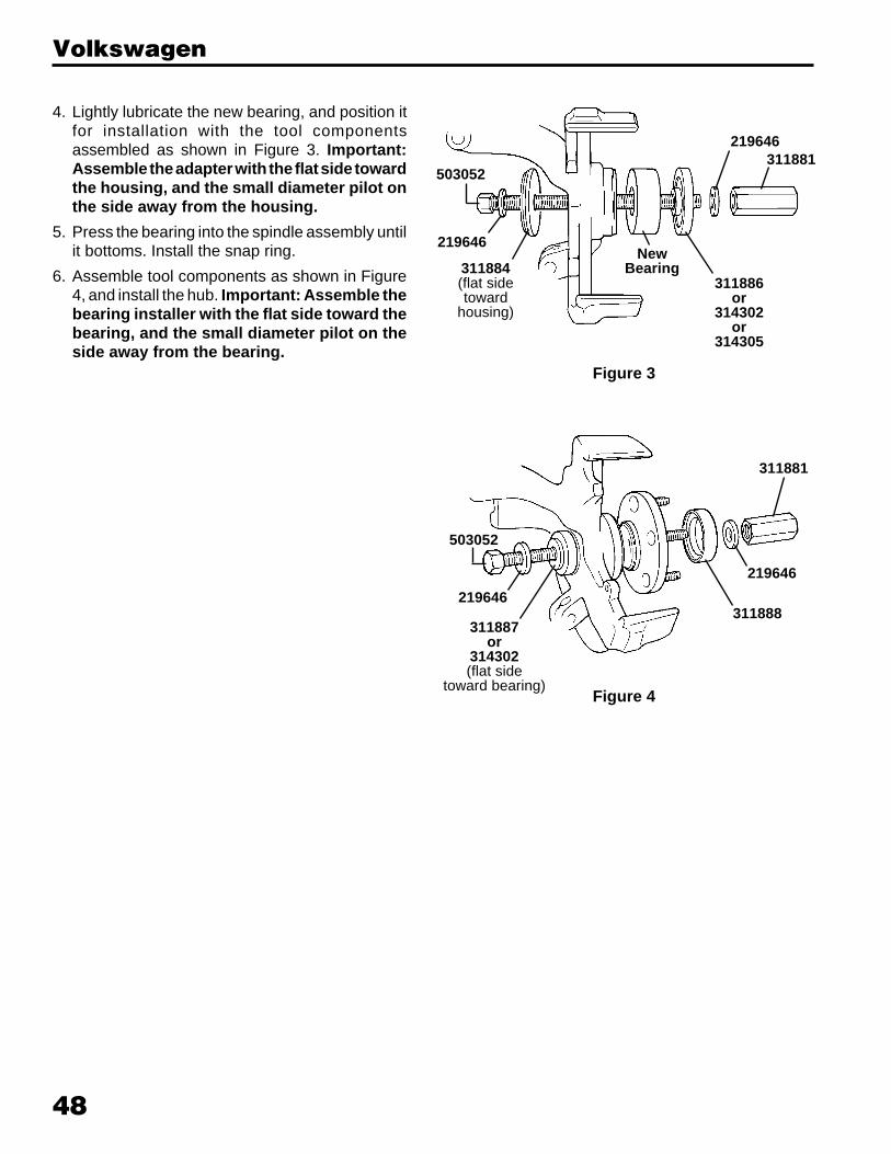
4. Lightly lubricate the new bearing, and position itfor installation with the tool componentsassembled as shown in Figure 3. Important:Assemble the adapter with the flat side towardthe housing, and the small diameter pilot onthe side away from the housing.
5. Press the bearing into the spindle assembly untilit bottoms. Install the snap ring.
6. Assemble tool components as shown in Figure4, and install the hub. Important: Assemble thebearing installer with the flat side toward thebearing, and the small diameter pilot on theside away from the bearing.
219646
311884(flat sidetoward
housing)
NewBearing
311886or
314302or
314305
311881219646
Figure 3
311881
503052
219646311888
219646
Figure 4
503052
311887or
314302(flat side
toward bearing)

Lifetime Marathon Warranty®
Effective 4-1-84; Rev. 5-15-00
THIS WARRANTY IS EXPRESSLY LIMITED TO ORIGINALRETAIL BUYERS OF SPX’s OTC BRAND PRODUCTS OR PARTS(“OTC PRODUCTS”). THIS WARRANTY IS NOT ASSIGNABLEOR TRANSFERABLE. SPX MAKES NO WARRANTY TOANYONE ELSE, INCLUDING OTHER PURCHASERS AND/ORUSERS, AND NONE SHALL BE IMPLIED.
Except as otherwise provided in this warranty, OTC Products are warranted against defects in materials andworkmanship for the life of the OTC Product, meaning that point in time when the OTC Product no longerfunctions due to normal wear. This warranty does not apply to electronic products, which are covered byseparate warranties. Nor does this warranty apply to the following items, which may be incorporated intoor sold with OTC Products and which are sold “as-is” with all faults: chains, batteries, electric motors, knives,and cutter blades. (Electric motors are warranted by their manufacturers under conditions stated in theirwarranties.)
The sole and exclusive remedy for any OTC Product found to be defective is repair or replacement, at theoption of SPX. If this exclusive remedy is deemed to have failed of its essential purpose, SPX’s liability shallnot exceed the purchase price of the OTC Product. In no event will SPX be liable for any direct, indirect,special, incidental, or consequential damages (including lost profit) whether based on warranty, contract,tort, or any other legal theory.
This warranty does not cover any OTC Product that has been abused, altered, worn out, contaminated,rusted, heated, ground, damaged due to side loading, used for a purpose other than that for which it wasintended, or used in a manner inconsistent with SPX/OTC’s instructions regarding use. The existence ofa defect shall be determined by SPX in accordance with procedures established by SPX. No one isauthorized to make any statement or representation altering the terms of this warranty.
THIS WARRANTY IS IN LIEU OF ANY OTHER WARRANTY, EXPRESS OR IMPLIED, INCLUDING ANYWARRANTY OF MERCHANTABILITY OR FITNESS FOR A PARTICULAR PURPOSE.
SOFTWAREThe above warranty applies to OTC Product software except that, instead of warranting against defects inmaterials and workmanship, SPX warrants that OTC Product software, when correctly installed, willexecute its programmed instructions. SPX does not warrant that software will operate uninterrupted or error-free. OTC Product software is proprietary, confidential information protected under copyright law. Usershave no right in or title to OTC Product software other than a limited right of use revocable by SPX. OTCProduct software may not be transferred or disclosed without the written consent of SPX and may not becopied except in ordinary backup procedures.
REPAIRShould your OTC Product require repair service, return it freight prepaid to an OTC authorized servicecenter, and provide proof of purchase. If the OTC Product is covered by warranty, SPX will return therepaired OTC Product, or a replacement, ground freight prepaid. If the OTC Product is determined to beout of warranty, it will be repaired for a reasonable charge plus return freight.
LIFETIMEMARATHON WARRANTYMARATHON WARRANTYLIFETIME
SPX CorporationSPX Corporation

Form No. 106430© SPX CorporationAugust 27, 2004, Rev. B
SPX Corporation655 Eisenhower DriveOwatonna, MN 55060-0995 USAPhone: (507) 455-7000Tech. Serv.: (800) 533-6127 Fax: (800) 955-8329Order Entry: (800) 533-6127 Fax: (800) 283-8665International Sales: (507) 455-7223 Fax: (507) 455-7063