
FRONT LOADER - Steel Valley Trail
44
OPERATOR'S MANUAL KUBOTA FRONT LOADER MODEL LA434 1AIABCPAP0350 READ AND SAVE THIS MANUAL Kubol-o
Transcript of FRONT LOADER - Steel Valley Trail

OPERATOR'S MANUAL
KUBOTAFRONT LOADER
MODEL LA434
1AIABCPAP0350
READ AND SAVE THIS MANUALKubol-o

ABBREVIATION LIST
Abbreviations Definitions
2WD 2-Wheel Drive
4WD 4-Wheel Drive
API Annerican Petroleum Institute
ASABE American Society of Agricultural and Biological Engineers, USA
ASTM American Society of Testing and Materials, USA
DIN Deutsches Institut fiir Normung, GERMANY
DT Dual Traction [4WD]
fpm Feet Per Minute
GST Glide Shift Transmission
Hi-Lo High Speed-Low Speed
HST Hydrostatic Transmission
m/s Meters Per Second
PTO Power Take Off
RH/LH Right-hand and left-hand sides are determined by facing in thedirection of forward travel
ROPS Roll-Over Protective Structures
rpm Revolutions Per Minute
r/s Revolutions Per Second
SAE Society of Automotive Engineers, USA
SMV Slow Moving Vehicle

FOREWORDYou are now the proud owner of a KUBOTA Loader. This loader is a product ofKUBOTA quality engineering and manufacturing. It is made of fine materials andunder a rigid quality control system. It will give you long, satisfactory service. Toobtain the best use of your loader, please read this manual carefully. Ifyour tractoris provided with CAB, also read the CAB operator's manual, which is a separatemanual. It will help you become familiar with the operation of the loader andcontains many helpful hints about loader maintenance. It is KUBOTA's policy toutilize as quickly as possible every advance in our research. The immediate use ofnew techniques in the manufacture of products may cause some small parts of thismanual to be outdated. KUBOTA distributors and dealers will have the most up-to-date information. Please do not hesitate to consult with them.
A SAFETY FIRSTThis symbol, the industry's "Safety Alert Symbol", is used throughout this manualand on labels on the mower itself to warn of the possibility of personal injury. Readthese instmctions carefully. It is essential that you read the instructions and safetyregulations before you attempt to assemble or use this unit.
DANGER: Indicates an imminently hazardous situation which, if notavoided, will result in death or serious injury.
WARNING : Indicates a potentially hazardous situation which, if notavoided, could result in death or serious injury.
CAUTION : Indicates a potentially hazardous situation which, if notavoided, could result in minor or moderate injury.
IMPORTANT: Indicates that equipment or property damage could result ifinstructions are not followed.
NOTE: Gives helpful information.

ASAFE OPERATION A-1
SERVICING OF LOADER 1
SPECIFICATIONS 2SUITABLE TRACTOR 2LOADER SPECIFICATIONS 2BUCKET SPECIFICATIONS 3DIMENSIONAL SPECIFICATIONS 3OPERATIONAL SPECIFICATIONS 4LOADER TERMINOLOGY 6
PRE-OPERATION CHECK 7
LUBRICATION 7
TRANSMISSION FLUID 7
REAR BALLAST 8
Liquid ballast in rear tires 8TIRE INFLATION 9
Inflation pressure 9TEST OPERATION 9
4 Position bucket control valve type 9REMOVING AIR FROM THE HYDRAULIC SYSTEM 9
DUAL REMOTE HYDRAULIC CONTROL SYSTEM 10
Control Lever and Hydraulic Hose Connections 10Loader / Remote Control Valve Lever 10
OPERATING THE LOADER 11
FILLING THE BUCKET 11
LIFTING THE LOAD 11CARRYING THE LOAD 12DUMPING THE BUCKET 12LOWERING THE BUCKET 12OPERATING WITH FLOAT CONTROL 12LOADING FROM A BANK 13PEELING AND SCRAPING 13LOADING LOW TRUCKS OR SPREADERS FROM A PILE 14BACKFILLING 14HANDLING LARGE HEAVY OBJECTS 15VALVE LOCK 15FRONT REMOTE HYDRAULIC CONTROL SYSTEM (if equipped) 16
Install the Coupler 16Control Switch 16Remote Control Coupler Connecting and Disconnecting 17
ATTACHING ATTACHMENTS 18DETACHING ATTACHMENTS 20DISMOUNTING THE LOADER 20ATTACHMENTS 20
Bucket 20

CONTENTS
Pallet fork 21
Snow blade 21
ASSEMBLE PALLET FORK 21
MAINTENANCE 23
LUBRICATION 23RE-TIGHTENING OF HARDWARE 23DAILY CHECKS 24EVERY 50 HOURS 25
Checking main frame bolt and nut torque 25General torque specification 26
REMOVING THE LOADER 27
STORING THE LOADER 29
REINSTALLING THE LOADER 30

SAFE OPERATION
Most loader equipment accidents can be avoided by following simple safety precautions.These safety precautions, iffollowed at all times, will help you operate your loader safely.
1. BEFORE OPERATING THE LOADER
1. Read and understand all instructions and precautionsfound in both the tractor and the loader operator'smanuals before using the loader.Lack of knowledge can lead to accidents.
2. It is the owner's responsibility to ensure that anyonewho will operate the loader reads this manual first andbecomes familiar with the safe operation of the loader.
3. For your safety, a ROPS with a seat belt is stronglyrecommended by KUBOTA in almost all applications.If your tractor has a foldable ROPS, fold it down onlywhen absolutely necessary and raise it up and lock itagain as soon as possible. Do not wear the seat beltwhen a foldable ROPS is down or a fixed ROPS is
removed. Ifyou have any questions, consult your localKUBOTA dealer.
Always use the seat belt when the tractor is equippedwith a ROPS. Never use the seat belt when the tractor
is not equipped with a ROPS.4. Visually check for hydraulic leaks and broken, missing,
or malfunctioning parts.Make necessary repairs before operating.
5. Replace damaged or illegible safety labels. Seefollowing pages for required labels.
6. When the front loader is mounted on the tractor, enterand exit the operator's seat only from left side of thetractor.
7. Engage the loader control valve lock to preventaccidental actuation when the implement is not in useor during transport. Do not utilize the valve lock formachine maintenance or repair.
8. Assemble, remove and reinstall the loader only asdirected in this manual. Failure to do this could result
in serious personal injury or death.9. Follow the precautions below when attaching
attachments.
• Make sure both handles (LH, RH) contact the earplates at the points (A) and are all the way down.
• Make sure both lock pins (LH, RH) protrude throughthe pin slots.
• Kubota recommends the use of Kubota attachments
on Kubota loaders. Non-Kubota attachments, if used,must comply with ISO 24410, first edition 2005-04-15.
• Use of a non-Kubota attachment that does not complywith ISO 24410 or the improper positioning ofhandle(s) or non-protrusion of pin(s) may result indetachment of the attachment or deformation, causingloss of performance, personal injury or death.
1AIABDDAP015A
(1) Handle(2) Ear plate(3) Pin slot(4) Lock pin
SAFE OPERATION A-1
(A) The handle contacts the earplate at the points.

A-2 SAFE OPERATION
2. OPERATING THE LOADER
1.
6.
7.
8.
Operate the loader only when properly seated at thecontrols. Do not operate from the ground.Move and turn the tractor at low speeds.Never allow anyone to get under the loader bucket orreach through the boom when the bucket is raised.Keep children, others and livestock away whenoperating loader and tractor.Do not walk or work under a raised loader bucket or
attachment unless it is securely blocked and held inposition.For tractor stability and operator safety, rear ballastmust be added to the 3-point hitch and to the rearwheels when using loader.To increase stability adjust the rear wheels to thewidest setting that is suitable for your application.Exercise extra caution when operating the loader witha raised bucket or attachment.
9. Do not lift or carry any person on the loader, in thebucket, or other attachment.
10.Avoid loose fill, rocks and holes. They can bedangerous for loader operation or movement.
11 .Avoid overhead wires and obstacles when the loader
is raised. Contacting electric lines can causeelectrocution.
12. Gradually stop the loader boom when lowering orlifting.
13. Use caution when handling loose or shiftable loads.14. Using loaders for handling large, heavy, or shiftable
objects is not recommended without proper handlingattachments.
15. Handling large heavy objects can be extremelydangerous due to:• Danger of rolling the tractor over.• Danger of upending the tractor.• Danger of the object rolling or sliding down the
loader boom onto the operator.16. Ifyou must perform this sort of work (item 15), protect
yourself by:• Never lift the load higher than necessary to clear
the ground.• Add rear ballast to the tractor to compensate for the
load or use rear implement.• Never lift large objects with equipment that may
permit them to roll back onto the operator.• Move slowly and carefully, avoiding rough terrain.
17. Never lift or pull a load from any point on the loaderwith a chain, rope, or cable. Doing so could cause arollover or serious damage to the loader.
18. Be extra careful when operating the tractor on a slope,always operate up and down, never across the slope.Do not operate on steep slopes or unstable surfaces.
19. When operating another implement on a hillside, besure to remove the loader to reduce the risk of rollover.
20. Carry loader boom at a low position during transport.(You should be able to see over the bucket.)
21 .Allow for the loader length when making turns.
3. AFTER OPERATING THE LOADER
1. When loader work is complete and parking or storing,choose flat and hard ground. Lower the loader boomto the ground, stop the engine, set the brakes andremove the key before leaving the tractor seat.
2. Make sure the detached loader is on stands and on a
hard, level surface.3. Before disconnecting hydraulic lines, relieve all
hydraulic pressure by moving the controls.4. Do not remove the loader from the tractor without an
approved bucket attached.
4. SERVICING THE LOADER
1. Always wear safety goggles when servicing orrepairing the machine.
2. Do not modify the loader. Unauthorized modificationmay affect the function of the loader, which may resultin personal injury.
3. Do not use the loader as a work platform or a jack tosupport the tractor for servicing or maintenance.Securely support the tractor or any machine elementswith stands or suitable blocking before workingunderneath.
For your safety, do not work under any hydraulicallysupported devices. They can settle or suddenly leakdown or be accidentally lowered.
4. Escaping hydraulic oil under pressure can havesufficient force to penetrate the skin, causing seriouspersonal injury. Do not use hands to search forsuspected leaks. If injured by escaping fluid, obtainmedical treatment immediately.
5. Do not tamper with the relief valve setting. The reliefvalve is pre-set at the factory. Changing the settingcan cause overloading of the loader and tractor whichmay result in serious personal injury.
6. When servicing or replacing pins in cylinder ends,bucket, etc., always use a brass drift and hammer.Failure to do so could result in injury from flying metalfragments.

DANGER,WARNING AND CAUTION LABELS
1AIABCPAP012B
1AIABCPAP013A
(3) Part No. 7J061-5649-1 (4) Part No. 7J246-5642-1
AWARNING
TO AVOID INJURY
FROM CRUSHING :
i.Do not utilize the valve lock formachine maintenance or repair.
z.The valve lock is to preventaccidental actuation whenimplement is not in useor duringtransport.
1AIABACAP084A
A DANGER
TO AVOID SERIOUS INJURYOR DEATH CAUSED BYCONTACT WITH ELECTRICUNES:• Check overhead clearance.
1AIABAHAP018A
SAFE OPERATION A-3
(1) Part No. 7J246-5643-1 (2) Part No. 7J246-5641-1
A DANGER
TO AVOID SERIOUS INJURYOR DEATH CAUSED BYFALLING LOADS:1. Load on raised bucket or fork
can fall or roll back ontooperator causing seriousinjury or death.
2. Use approved clamping and/ or guard attachments forhandling large, loose orshiftable loads such as bales,posts, sheets of plywood etc.
3. Carry loads as low as possible.
1AIABAHAP016A
(5) Part No. 7J061-5645-1
AWARNINGTO AVOID PERSONAL
INJURY:
1. Observe safety precautionsin loader and tractor
Operator's Manual.2. Operate the loader from
tractor seat only.3. Keep children, others and
livestock away when operating loader and tractor.
4. Avoid holes, loose ground,and rocks which may causetractor / loader to tip.
5. Make sure approved bucketis attached before removingloader from tractor.
6. When parking or storing,choose flat and hard ground.Lower the bucket to theground, set brakes andremove key before leavingtractor.
7. Before disconnecting hydraulic lines, relieve all hydraulicpressure.
1AIABAHAP043A
A DANGER
TO AVOID SERIOUS INJURY
OR DEATH CAUSED BYROLLOVERS:1. ROPS and a fastened seat belt
are strongly recommended inalmost all applications. FoldableROPS should be in upright andlocked position if equipped.
2. Adjust rear wheels to the widestsetting that is suitable forthe work.
3. Add recommended wheelballast and rear weight forstability.
4. DO NOT drive on steep slopesor unstable surfaces.
5. Carry loader arms at lowposition during transport.IVlove and turn tractor at slowspeeds.
1AIABAHAP017A
(6) Part No. 7J246-5644-2(Both sides)
AWARN NG
aTO AVOID INJURY
FROM FALLS OR
BEING CRUSHED :
1. DO NOT stand or work underraised loader or bucket.
2. DO NOT use loader as jackfor servicing.
3. DO NOT use loader as awork platform.
4. NEVER connect chain, cableor rope to loader bucket whileoperatinq loader.
1AIABAHAP020A

A-4 SAFE OPERATION
(1) Part No. 7J802-3648-5
ADANGERVOID PERSONAL INJURY OR DEATH
Make sure both handles
ILH, RH)® contacttheearplates(B) at theSic points and are allthe way down.
2.Make sure both lock
pins (LH, RH)©protrude through the
Kubota recommends the use of Kubota Use ofa non-Kubota attachment that does i
attachments on Kubota loaders with ISO 24410 or the improper positNon-Kubotaattachments, ifused, handle(s)or non-protrusion of pin(s)mamust complywith ISO 24410, first detachment oftheattachment ordeformatioedition 2005-04-15. lossof performance, personalinjury ordeat
1AIABAAAP119A
(2) Part No. 7J246-5643-1 (3) Part No. 7J048-3923-5 [B2366 Quick Coupler]
A DANGER
TO AVOID SERIOUS INJURYOR DEATH CAUSED BYFALLING LOADS:1. Load on raised bucket or fork
operator causing seriousinjury or death.
2. Use approved clamping and/ or guard attachments forhandling large, loose orshiftable loads such as bales,posts, sheets of plywood etc.
1AIABACAP075A
ADANGERPALLET FORK
RATED CAPACITYRated capacity
U«3,LA504,Ui534 :600 LBS.:390 LBS.LA434
TO AVOID PERSONALINJURY OR DEATH
CAUSED BY ROLLOVER
•Do not exceed ratedload listed above.
•Use rear implement and tireballast recommended in loaderoperator's manual.
•Operate tractor slowlytaking special carewhen turning.
1AIABDDAP008G
1AIABDDAP018B
[B2376 Pallet Fork]
1AIABDDAP035A
1AIABCPAP030A

SAFE OPERATION A-5
CARE OF DANGER,WARNING AND CAUTION LABELS
1. Keep danger, warning and caution labels clean and free from obstructing material.2. Clean danger, warning and caution labels with soap and water, dry with a soft cloth.3. Replace damaged or missing danger, warning and caution labels with new labels from your local KUBOTA dealer.4. If a component with danger, warning and caution label (s) affixed is replaced with new part, make sure new label (s) is
(are) attached In the same location (s) as the replaced component.5. Mount new danger, warning and caution labels by applying on a clean dry surface and pressing any bubbles to outside
edge.

SERVICING OF LOADER
Your dealer is interested in your new loader and has thedesire to help you get the most value from it. After readingthis manual thoroughly, you will find that you can do someof the regular maintenance yourself.However, when in need of parts or major service, be sureto see your KUBOTAdealer.For service, contact the KUBOTA dealership from which
you purchased your loader or your local KUBOTAdealer.When in need of parts, be prepared to give your dealer theloader serial number.
Locate the serial numbers now and record them in the
space provided.
KUBOTA LOADER
Model
Serial Number
Date of Purchase
Name of Dealer
(To be filled in by purchaser)
1AIABDDAP009A
(1) Serial number
SERVICING OF LOADER 1

SPECIFICATIONS
SPECIFICATIONS
SUITABLE TRACTORLA434: B2301, B2601
LOADER SPECIFICATIONS
LOADER MODEL LA434
TRACTOR MODEL B2301, B2601
WHEEL BASE (WB) mm (in.) 1563 (61.5)
FRONT TIRES 7-12
REAR TIRES 11.2-16
BOOM CYLINDERBORE mm (in.) 45(1.77)
STROKE mm (in.) 349(13.7)
BUCKET CYLINDERBORE mm (in.) 45 (1.77)
STROKE mm (in.) 336(13.2)
CONTROL VALVEOne Detent Float Position, Two Stage Bucket Dump,
Power Beyond Circuit
RATED FLOW L/min (GPM) 17.9 (4.7)
MAXIMUM PRESSURE MPa (kg/cm', psi) 13.8 (141,2000)
NET WEIGHT (APPROXIMATE) kg (lbs.) 208 (459)

SPECIFICATIONS
BUCKET SPECIFICATIONS
LOADER MODEL LA434
MODEL SQUARE 50" SQUARE 54" SQUARE 60" LM
TYPE RIGID QUICK ATTACH RIGID QUICK ATTACH
WIDTH mm (in.) 1270 (50) 1370 (54) 1525(60.0)
DEPTH (L) mm (in.) 478 (18.8) 456(18) 529 (20.8)
HEIGHT (M) mm (in.) 483 (19.0) 562 (22.1) 562 (22.1)
LENGTH (N) mm (in.) 523 (20.6) 495(19.5) 566 (22.3)
CAPACITYSTRUCK m' (CU.FT.) 0.154(5.4) 0.19(6.7) 0.23 (8.1)
HEAPED m^ (CU.FT.) 0.184(6.5) 0.25 (8.8) 0.29 (10.2)
WEIGHT kg (lbs.) 68 (150) 90 (198) 98 (216) 103 (227)
DIMENSIONAL SPECIFICATIONS
LOADER MODEL LA434
TRACTOR MODEL B2301,B2601
A MAX. LIFT HEIGHT (TO BUCKET PIVOT PIN) mm (in.) 1995(78.5)
B MAX. LIFT HEIGHT UNDER LEVEL BUCKET mm (in.) 1853 (72.9)
C CLEARANCE WITH BUCKET DUMPED mm (in.) 1568(61.7)
DREACH AT MAX. LIFT HEIGHT
(DUMPING REACH)mm (in.) 393(15.4)
E MAX. DUMP ANGLE deg. 40
F REACH WITH BUCKET ON GROUND mm (in.) 1293 (50.9)
G BUCKET ROLL-BACK ANGLE deg. 25
H DIGGING DEPTH mm (in.) 96 (3.8)
J OVERALL HEIGHT IN CARRYING POSITION mm (in.) 1108(43.6)

SPECIFICATIONS
OPERATIONAL SPECIFICATIONS
LOADER MODEL LA434
TRACTOR MODEL B2301, B2601
u LIFT CAPACITY (BUCKET PIVOT PIN, MAX. HEIGHT) kg (lbs.) 430 (948)
V LIFT CAPACITY (500 mm FORWARD, MAX. HEIGHT) kg (lbs.) 299 (659)
w LIFT CAPACITY (BUCKET PIVOT PIN, 1500 mm HEIGHT) kg (lbs.) 533 (1175)
X LIFT CAPACITY (500 mm FORWARD, 1500 mm HEIGHT) kg (lbs.) 394 (868)
Y BREAKOUT FORCE (BUCKET PIVOT PIN) N (Ibf.) 9546 (2146)
z BREAKOUT FORCE (500 mm FORWARD) N (Ibf.) 6763(1520)
w BUCKET ROLL-BACK FORCE AT MAX. HEIGHT N (Ibf.) 8111 (1823)
XX BUCKET ROLL-BACK FORCE AT 1500 mm HEIGHT N (Ibf.) 9645 (2168)
zz BUCKET ROLL-BACK FORCE AT GROUND LEVEL N (Ibf.) 7726 (1737)
RAISING TIME sec. 3.7
LOWERING TIME sec. 2.7
BUCKET DUMPING TIME sec. 1.9
BUCKET ROLLBACK TIME sec. 2.6
1
N
1AIABACAP003A
--c"
WB F
500mm
^500mm^^Y Z

2000
1500
EB
2 1000?(D
X
500
\\*
pivot pin
\^^500\of pi\
Tim fon/vard
/ot pin
* \\ \
1500
1AIABCPAP016A
500 1000
Lift Capacity (kg)
2000
1500
EE
r 1000
0
I
500
SPECIFICATIONS
5 10
Rollback Force (kN)
15

6 SPECIFICATIONS
LOADER TERMINOLOGY
Q
1AIABCPAP031A
(1) Side frame (6)(2) Loader control lever (7)(3) Mounting pin (8)(4) Main frame (9)(5) Boom cylinder
1AIABCPAP029A

PRE-OPERATION CHECK
PRE-OPERATION CHECK
LUBRICATIONLubricate all grease fittings with SAE multipurposegrease.
1AIABCPAP017A
[Quick coupler type (Option)]
4FAAABXAP144A
TRANSMISSION FLUIDCheck the tractor transmission fluid level. Add fluid if
necessary. Refer to the tractor operator's manual forinstructions and proper fluid. Repeat this check afterpurging air from the system. At that time, it will benecessary to add transmission fluid.
1AIABDDAP021A
(1)Dipstick(Rear) (A) Oillevel is acceptable within this range.(2) Oil inlet
IMPORTANT:• To check the tractor transmission fluid level, lower the
bucket to the ground and lower the 3 point hitch.

8 PRE-OPERATION CHECK
REAR BALLAST
A WARNINGTo avoid serious injury:• For tractor stability and operator's safety, rear
ballast should be added to the rear of the
tractor in the form of 3-point counter weightand rear wheel ballast. The amount of rear
ballast will depend on the application.
Implement as Counter Weight
LA434
Box Blade Approx. 170 kg (375 lbs.)
Rear Blade Approx. 160 kg (350 lbs.)
Rotary Tiller Approx. 195 kg (430 lbs.)
Back Hoe Approx. 320 kg (700 lbs.)
*When filling 15-19.5 tires with water, the counter weightshould be approx.136 kg (300 lbs.) in weight.
•Liquid ballast in rear tiresWater and calcium chloride solution provides a safe andeconomical ballast. Used properly, itwill not damage tires,tubes or rims. The addition of calcium chloride is
recommended to prevent the water from freezing. Use ofthis method of weighting the wheels has full approval ofthe tire manufacturers. See your tire dealer for thisservice.
Liquid weight per tire (75 Percent filled)
Tire sizes 9.5-16 11.2-16 12.4-16 15-19.5
Slush free at
-10r(14T)Solid at-30X:{-22T)[Approx. 1 kg (2 lbs.)CaClz per4L(1 gal.) ofwater]
54 kg(119 lbs.)
70 kg(155 lbs.)
85kg(187 lbs.)
140kg(309 lbs.)
Slush free at -241:
(-11 T)Solid at -47t:(-53T)[Approx. 1.5 kg (3.3lbs.) CaClz per4 L(1 gal.) of water]
57 kg(126 lbs.)
74 kg(163 lbs.)
89 kg(196 lbs.)
150 kg(331 lbs.)
Slush free at -47 X:
(-53 T)Solid at-52(-62 T)[Approx. 2.25 kg(5 lbs.) CaClz per4L(1 gal.) of water]
60 kg(132 lbs.)
78 kg(172 lbs.)
94kg(207 lbs.)
160kg(353 lbs.)
IMPORTAIMT:• Do not fill tires with water or solution more than 75% of
full capacity (to the valve stem level at 12 o'clockposition).
1AIABACAP010A
(1)Air(2) Water
(A) Correct: 75% FullAir compresses like a cushion
(B) Incorrect: 100% FullWater can not be compressed
NOTE:• When mounting a heavy rear implement, liquid in the
tires may not be required.
IMPORTAIMT:• Do not add liquid ballast or any other weights to the
front tires.
• While the backhoe is installed on the tractor, the liquidballast in the rear tires should be removed.
• When filling 15-19.5 tires with water, the counterweight should be between 91 kg and 182 (200 lbs and400 lbs.) in weight.

TIRE INFLATIONEnsure that the tractor tires are properly inflated.Refer to the tractor operator's manual for optional tires.
•Inflation pressure
Tire sizes Inflation Pressure
9.5-16, 4PR 140kPa(1.4kgf/cm^ 20psi)
11.2-16,4PR 130kPa(1.3kgf/cm^ 18psi)
Rear 12- 16.5,4PR 270kPa(2.7kgf/cm^ 40psi)
31x15.5-15, 4PR 140kPa(1.4kgf/cm^ 20psi)
33x12.5-15, 4PR 140kPa{1.4kgf/cm', 20psi)
6-12, 4PR 200kPa(2.0kgf/cm^ 28psi)
7-12, 4PR 170kPa(1.7kgf/cm^ 24psi)
Front 21x8.00-10, 4PR 160kPa(1.6kgf/cm', 23psi)
23x8.50-12Turf, 4PR 150kPa(1.5kgf/cm^ 22psi)
23x8.50-12lnd..4PR 250kPa(2.5kgf/cm^ 35psi)
TEST OPERATION
A WARNINGTo avoid serious personal injury:
Keep engine speed at low idle during the testoperation.Escaping hydraulic fluid under pressure canhave sufficient force to penetrate skin, causingserious personal Injury.Before disconnecting lines, be sure to relieveall pressure by moving the controls.Before applying pressure to the system, besure ail connections are tight and that lines,tubes and hoses are not damaged.Fluid escaping from a very small hole can bealmost Invisible. Use a piece of cardboard orwood, rather than your hands to search forsuspected leaks.If injured by escaping fluid, see a doctor atonce. Serious infection or allergic reaction willdevelop If proper medical treatment is notadministered immediately.
PRE-OPERATION CHECK
1AIABACAP011B
NOTE:• When the lever is at each comer position marked by
asterisk (*) or lower left, boom and bucket cylinderswork at the same time. However, the lower left position(Raise & Roll back) is not recommended for scoopingbecause of insufficient lift force.
To begin a test operation, slightly move the control leverfrom the "N" position. Slowly raise the loader boom justenough for the bucket to clear the ground when fullydumped. Slowly work through the dump and roll backcycles.
IMPORTANT:• If the boom or bucket does not work in the directions
indicated on the label, lower the bucket to the ground,stop the engine, and relieve all hydraulic pressure.Recheck and correct all hydraulic connections and oillevel.
•4 Position bucket control valve typeThis control valve has two stage dump positions. The firstdump position by moving the lever to the right featuresgreater speed for dumping.The second dump position (to further right) is the"Regular" dump position. It has good power and controlfor dumping precisely. This position should be used whenoperating another implement with this control valve.These two positions are separated by a "Feel" position foryour convenience.
REMOVING AIR FROM THE HYDRAULICSYSTEMRepeat raising and lowering the boom and bucketoperations until all the air is removed from the system andthe system responds properly.
IMPORTANT:• Do not move the control lever into the float position
when the bucket is off the ground.

10 PRE-OPERATION CHECK
DUAL REMOTE HYDRAULIC CONTROLSYSTEMThe tractor is equipped with the double-acting 2-segmenthydraulic control valve for front loader.To apply the hydraulic power take-off for generalattachments, keep the following point in mind.
•Control Lever and Hydraulic HoseConnections
Connect the control lever in its specified direction and thehydraulic hoses to their specified ports.
White
© [C] Blue
[B] Yellow
1AGAECDAP004B
(1) Loader/Remote control valve lever (R) "RIGHT"(L) "LEFT"(U) "UP"(D) "DOWN"
Pressure
Hydraulic outlet ports of first segment Returning
Lever UP DOWN
Port[A] In 4— Out —1>
[B] Out —> In i—
Hydraulic outlet ports of second segment
Lever RIGHT LEFT
Port[C] In i— Out —0
[D] Out —0 In i—
IMPORTANT:To avoid damage of the attachments:
• Do not connect attachments through the hydraulicmotor to the [C] and [D] ports. If the control lever ismoved to the Regeneration position (R1), the seals onthe hydraulic motor will be damaged.
• This control valve is provided with the Regenerationposition. When the [C] and [D] ports are used to takeoff hydraulic power for the hydraulic cylinder, be sureto connect the [C] port to the "Head-End" side port ofthe hydraulic cylinder.
• Make the following connections when using this valveto take off hydraulic power for the hydraulic cylinder.
Colored Coupler Hydraulic Cylinder port
[B: Yellow], [C: Blue] Head-End side
[A: White], [D: Red] Rod-End side
•Loader I Remote Control Valve Lever
1. Before moving the lever, make sure that the hydraulichoses for attachments are connected.
2. Move the lever diagonally (a, b, c shown in the figure),and the first and second segments can be controlledat once.
1AGAECDAP009F
NOTE:• Move the lever to the "FLOAT' position, and it will be
held there by the detent mechanism. To use the valveas a floating valve with detents, connect the hydraulichoses to ports [A] and [B].
• When taking off hydraulic power from port [D], the flowrate can be adjusted in 2 stages with the lever.The flow rate is high at position (R1) and low atposition (R2). Move the lever to position (R1) or (R2)depending on the attachment in use.

OPERATING THE LOADER 11
OPERATING THE LOADER
The loader should be operated with the tractor enginespeed depending on the application and the operator'slevel of experience. Excessive speeds are dangerous,and may cause bucket spillage and unnecessary strain onthe tractor and loader.
When operating in temperatures below -1 "C(30T), runthe tractor engine below 1200 rpm until the oiltemperature exceeds -1 "C(30 °F).The following text and illustrations offer suggested loaderand tractor operating techniques.
A WARNINGTo reduce the possibility of roll over:• It is not recommended that the loader be
attached when operating another implement ona hillside.
IIVIPORTANT:• Before operating the loader in rough terrain, remove
the mower to avoid damage to the mower.
FILLING THE BUCKETApproach and enter the pile with a level bucket.
1AIABACAP012A
Ease control lever toward you and then left to rollback andlift the bucket.
I
1AGAECDAP009H
The rollback and lifting of the bucket will increaseefficiency because a level bucket throughout the liftingcycle resists bucket lift and increases breakaway effort.
INCORRECT CORRECT
1AIABACAP014A
NOTE:• Do not be concerned if the bucket is not completely
filled during each pass. Maximum productivity isdetermined by the amount of material loaded in agiven period of time. Time is lost if two or moreattempts are made to fill the bucket on each pass.
LIFTING THE LOADWhen lifting the load, keep the bucket positioned to avoidspillage.
1AIABACAP015A
WARNINGTo avoid serious personal injury:• Do not attempt to lift bucket loads in excess of
the loader capacity.• Before raising the bucket to full height, make
sure the tractor is on level ground. If not, it maytip over, even if the tractor is not moving.
12 OPERATING THE LOADER
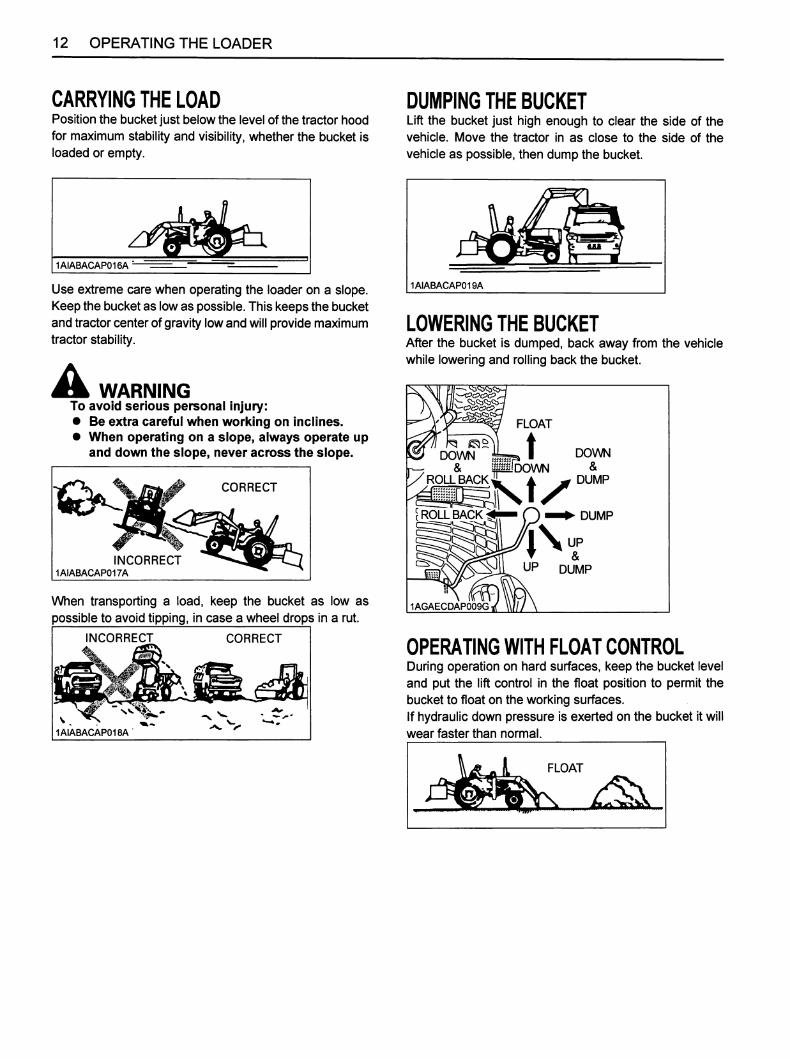
CARRYING THE LOADPosition the bucket just below the level of the tractor hoodfor maximum stability and visibility, whether the bucket isloaded or empty.
1AIABACAP016A
Use extreme care when operating the loader on a slope.Keep the bucket as lowas possible. This keeps the bucketand tractor center of gravity low and willprovide maximumtractor stability.
A WARNINGTo avoid serious personal injury:• Be extra careful when working on inclines.• When operating on a slope, always operate up
and down the slope, never across the slope.
INCORRECT1AIABACAP017A
CORRECT
When transporting a load, keep the bucket as low as
possible to avoid tipping, in case a wheel drops in a rut.
INCORRECT CORRECT
1AIABACAP018A
DUMPING THE BUCKETLift the bucket just high enough to clear the side of thevehicle. Move the tractor in as close to the side of the
vehicle as possible, then dump the bucket.
1AIABACAP019A
LOWERING THE BUCKETAfter the bucket is dumped, back away from the vehiclewhile lowering and rolling back the bucket.
DOWN
/ROLLBACK
{ROLLBACK
1AGAECDAP009G
FLOAT
DOWN
DOWN
&
DUMP
DUMP
^\upUP DUMP
OPERATING WITH FLOAT CONTROLDuring operation on hard surfaces, keep the bucket leveland put the lift control in the float position to permit thebucket to float on the working surfaces.If hydraulic down pressure is exerted on the bucket it willwear faster than normal.

The float position will also avoid mixingof surface materialwith stockpile material. The float position will reduce thechance of surface gouging while removing snow or othermaterial, or when working with a blade.
FLOAT
MSURFACE MATERIAL
LOADING FROM A BANKChoose a forward gear that provides a safe ground speedand power for loading.
1AIABACAP023A ^
To avoid serious personal injury:• Be extra carefui wlien working on inciines.• When operating on a slope, always operate up
and down the slope, never across the slope.
NOTE:• Loader lift and break-away capacity diminish as
loading height is increased.
Side cutting is a good technique for cutting down a bigpile. Wheel width should not exceed the bucket width forthis procedure.
1AIABACAP024A
If the pile sides are too high and liable to cause cave-in,use the loader to break down the sides until a slot can be
cut over the top.
1AIABACAP025A
OPERATING THE LOADER 13
Another method for large dirt piles is to build a ramp toapproach the pile.
1AIABACAP026A
It is important to keep the bucket level when approachinga bank or pile. This will help avoid gouging the work area.
1AIABACAP027A
PEELING AND SCRAPINGUse a slight bucket down angle, travel fonward, and holdthe lift control forward to start the cut. Make a short cut
and break-out cleanly.
1AIABACAP028A
With the bucket level, start a cut at the notch
approximately 2 in. deep. Hold the depth by feathering thebucket control to adjust the cutting edge up or down.When the front tires enter the notch, adjust the boomcylinder to maintain proper depth.
1AIABACAP029A
Make additional passes until the desired depth is reached.During each pass, use only the bucket control while atworking depth. This will allow you to concentrate oncontrolling the bucket angle to maintain a precise cut.
1AIABACAP030A

14 OPERATING THE LOADER
LOADING LOW TRUCKS ORSPREADERSFROM A PILEFor faster loading, minimize the angle of turn and lengthof run between pile and spreader.
1AIABACAP031A
Backgrade occasionally with a loaded bucket to keep thework surface free of ruts and holes. Also, hold the lift
control forward so the full weight of the bucket is scrapingthe ground. Use the heel of the bucket
1AIABACAP032A
BACKFILLINGApproach the pile with the bucket flat.
CORRECT
1AIABACAP033A
Poor operating methods will move less dirt and make itmore difficult to hold a level grade.
INCORRECT
1AIABACAP034A
IMPORTANT:• Do not use the bucket in the dumped position for
bulldozing. As shown above, this method will imposesevere shock loads on the dump-linkage, the bucketcylinders, and the tractor.
Leave dirt in the bucket because dumping on each passwastes time.
•iOperate at right angles to the ditch. Taking as big a biteas the tractor can handle.
SOIL PILE

Leave dirt which drifts over the side of the bucket for final
cleanup.
,DITCH^p< \ N 'S V
H ;9 :8 ,i9 ,
Pile dirt on the high side for easier backfilling on a slope.
••V • • 1AIABACAP038A
HANDLING URGE HEAVY OBJECTS
A DANGERTo avoid serious personal injury or death:
Handling large, heavy objects can bedangerous due to:(A)Danger of rolling the tractor over.(B)Danger of upending the tractor.(C)Danger of the object rolling or sliding downthe loader boom onto the operator.If you must perform the above worit, protectyourself by:(A)Not lifting the load higher than necessary toclear the ground when moving.(B)Adding rear baiiast to the tractor tocompensate for the load.(C)Not lifting iarge objects with equipment thatdoes not have an anti-roiibacic device.
(D)IV!oving slowly and carefully.(E)Avoiding rough terrain.(F)Keeping transport distance as short aspossible and carry the load as low as possibleduring transport.
OPERATING THE LOADER 15
VALVE LOCK
A WARNINGTo avoid injury from crushing:• Do not utilize the valve loci< for machine
maintenance or repair.• The valve locl< is to prevent accidental
actuation when implement is not in use orduring transport.
The control valve is equipped with a valve lock feature.The control valve is locked in the neutral position.
The lock is not intended and will not prevent a leak downof the implement during the period of storage.
(1) Lock lever (A) ©"Lock"(B) ^ "Unlock"
1AIABCPAP037A

16 OPERATING THE LOADER
FRONT REMOTE HYDRAULIC CONTROLSYSTEM (if equipped)This system can be used for a front mounted hydraulicimplement, as it provides hydraulic oil to the front outletdirectly.
•Install the Coupler1. Remove the cap from the front hydraulic outlet.2. Install the hydraulic quick coupler as required.
Port B
1AIABCPAP036A
(1) Front hydraulic outlet(2) Hydraulic quick coupler (Not included in this kit)
•Control Switch
1. Front hydraulic valve main switchPush the front hydraulic valve main switch (1) toengage the front hydraulic valve.A light on the switch will illuminate to indicate that thefront hydraulic valve is on, and to enable the activationswitch (2).
2. Activation switch
(1) When pressing the "A" button, hydraulic oil willcome out of Port A and return through Port B aslong as the switch is pressed.
(2) When pressing the "B" button hydraulic oil willcome out of Port B and return through Port A aslong as the switch is pressed.
3. Push the front hydraulic valve main switch again todisengage the front hydraulic valve, and the light of thefront hydraulic valve main switch will turn off.
1AIABCPAP032A
(1) Front hydraulic valve main switch(2) Activation switch
V_
1AIABCJAP019A
DEPRESS
o-CEbJ)
(C) Front hydraulic valve main switch "OFF"(D) Front hydraulic valve main switch "ON"

IMPORTANT:• While a front mounted hydraulic attachment is used,
make sure the hydraulic hose is routed out of contactwith the left and right bucket links. (Keep the hose fromrunning over within the circled zone in the figurebelow.)
1AIABDDAP026A
A WARNINGTo avoid serious injury:• Valve lock does not lock out switch operated
third-function hydraulics, which are activewhen the key switch and the front hydraulicvalve main switch are ON.
OPERATING THE LOADER 17
•Remote Control Coupler Connecting andDisconnecting
A WARNINGTo avoid serious Injury:• Stop the engine and relieve pressure before
connecting or disconnecting lines.• Do not use your hand to check for leaks.
• Relieve Hydraulic Pressure1. Move the key switch to the "RUN" position.
NOTE:• Don't start the engine.
2. Push the front hydraulic valve main switch "ON".3. Press the activation switch A and B several times.
4. Push the front hydraulic valve main switch "OFF".5. Turn the key switch to the "OFF" position.
^ Connecting1. Clean both couplers.2. Remove dust plugs.3. Insert the implement coupler to the tractor hydraulic
coupler.4. Pull the implement coupler slightly to make sure
couplers are firmly connected.
^ Disconnecting1. Lower the implement first to the ground to release
hydraulic pressure in the hoses.2. Clean the couplers.3. Press the "Activation switch" a couple of times to
relieve hydraulic pressure.Pull the hose straight from the hydraulic coupler torelease it.
4. Clean oil and dust from the coupler, and then replacethe dust plugs.
NOTE:• Your local KUBOTA dealer can supply parts to adapt
couplers to hydraulic hoses.

18 OPERATING THE LOADER
ATTACHING ATTACHMENTSThis quick attach coupler is designed to be used withKubota attachments. Non-Kubota attachments, if used,must comply with ISO 24410, first edition 2005-04-15.This quick attach coupler allows the operator to changeeasily without the use of tools.
A DANGERTo avoid serious personal injury or death:• Use of a non-Kubota attachment that does not
comply with iS024410 or the improperpositioning of handle(s) or non-protrusion ofpin(s) may result in detachment of theattachment or deformation, causing loss ofperformance, personal injury or death.
NOTE:• Attachments should be located on a flat, firm surface
when attaching and detaching them from the quickattach coupler.
1.
2.
To mount an attachment, pull the handles of the quickattach coupler latching pins to the unlatched position.The quick attach coupler handles must be all the wayup to ensure that the latching pins are fully retracted.Position the tractor squarely in front of the attachmentand tilt the quick attach coupler forward with the bucketcylinders.
1AIABDDAP027A
(1) Quick attach coupler
3.
4.
Ease the quick attach coupler mounting plate into thesaddle of the attachment.
Roll the quick attach coupler back using the bucketcylinders and raise the boom slightly. The back of theattachment should rest against the front of the quickattach coupler mounting plate and the weight of theattachment should be supported by the loader.
1AIABDDAP028A
(1) Quick attach coupler
A WARNINGTo avoid serious injury or machine damage:• Raise the boom only enough to latch the
attachment.
The attachment could swing off the quickattach coupler.
5. When the attachment is properly seated in the saddleand against the front of the quick attach couplermounting plate, turn off the engine and set the parkingbrake. Push the quick attach coupler handles to thefully latched position. Verify both latching pins arecompletely engaged in the base of the attachment.
1AIABDDAP026B
(1) Quick attach coupler handle

A DANGERTo avoid serious personal injury or death:
The following engagement points are critical.1) The lock pins of the quicl( attach coupler
have to protrude into and through the pinslots of the attachment on both sides.
It is critical that the pins are in goodcondition and without visible signs of wearor damage and that the operator align theloader quick attach coupler with theattachment to allow the pins to go throughthe pin slots.
2) Both handles have to be pushed down untilthe handles contact the ear plates near thepoints where the pin bolt goes through thehandle (A).
3) Do not operate the tractor or attachmentunless all of the above conditions are met.
(p
I—
r/V1AIABDDAP015A
(1) Handle(2) Ear plate(3) Pin slot(4) Lock pin
(A) The handle contacts the earplate at the points.
OPERATING THE LOADER 19
6. Visually verify when pushing the quick attach couplerhandles into locked position that the latch pins rotatecompletely and are located underneath the stop of thequick attach coupler.
1AIABDDAP029A
(1) Latch pins(2) Quici<attach coupler stopper
7. When attaching different attachments visually inspectfor broken or damaged pins. If broken or damagedpins are found, replace before using. Use of brokenpins may result in attachment detachment ordeformation, causing loss of performance, personalinjury or death.
8. You are now ready to use the attached attachment. Allcompatible attachments attach and detach using thesame method.
A WARNINGTo avoid serious injury or machine damage:Never operate or transport attachments which arenot attached completely.Always replace damaged hardware immediately.

20 OPERATING THE LOADER
DETACHING AHACHMENTS1. Detaching attachments is done in the reverse of
attaching attachments. The procedure is below.2. Lower the attachment to ground level with the
attachment slightly in the rolled back position.Stop theengine and set the parking brake.
3. Pull the quick attach coupler handles to the unlatchedposition to release the latching pins.
4. While sitting in the tractor operator's seat, start theengine and slowly move the loader control lever to the"DUMP" position until the attachment is pushed awayslightlyfrom the quick attach coupler.
5. Lowerthe loader boom so that the quickattach couplermounting plate clears the attachment saddle.
6. Back away from the attachment slowly.7. If an attachment is not going to be attached to the
quick attach coupler immediately, push the handles ofthe quick attach coupler to the locked position toprevent damage to the handle assembly.
DISMOUNTING THE LOADER
A WARNINGTo avoid machine damage or serious injury:• Remove ioader from tractor oniy when an
approved ioader buclcet is attached.
Follow instructions provided in "REMOVINGLOADER" section in this operator's manual.
THE
AnACHMENTS•Bucket
4FAAAAMAP002B
-SQUARE 50" (RIGID)WIDTH
1 270 mm
STRUCK CAPACITY
0.154 cu.m.
-SQUARE 54" (QUICK)WIDTH
1 370 mm
STRUCK CAPACITY
0.19 cu.m.
-SQUARE 60" LM (RIGID)WIDTH
1 525 mm
STRUCK CAPACITY
0.23 cu.m.
-SQUARE 60" LM (QUICK)WIDTH
1 525 mm
STRUCK CAPACITY
0.23 cu.m.

•Pallet fork
1AIABDDAP040A
LOADER MODEL
LA434
ISnow blade
1AIABDDAP043A
RATED CAPACITY
177 kg (390 lbs.)
OPERATING THE LOADER 21
ASSEMBLE PALLET FORK1. Install the fork to the middle of the frame.
(fit the lower hook of the fork to the center notch of theframe)
1AIABDDAP041A
(1) Fork
2. Slide the fork to the desired position.
1AIABDDAP042A
(1) Fork
3. Push the lock lever and slide the fork slightly until thelock pin engages with one of the notches to lock thefolk.
unlock
1AIABACAP067C
(1) Lock lever

22 OPERATING THE LOADER
4. The other fork can be installed using the sameprocedures.
1AABDDAP040A

MAINTENANCE
A WARNINGTo avoid serious injury:• Be sure to checl( and service tlie tractor on a
flat surface with the bucl<et on the ground,engine shut off, the Itey removed and theparicing braice on.
LUBRICATION1. Lubricate all grease fittings every 10 hours of
operation. Also, lubricate joints of control lever linkageevery 10 hours. High quality grease designating"extreme pressure" and containing Molybdenumdisulfide is recommended. This grease may specify"l\/loly EP" on its label.
1AIABDDAP020A
2. Daily before operation, check the tractor hydraulic fluidlevel. If low, add as described in the tractor's operator'smanual. Also change the filter element and thehydraulic fluid as recommended in the tractor'soperator's manual.
MAINTENANCE 23
RE-TIGHTENING OF HARDWAREAfter 20 to 30 hours of initial loader operation, re-tightenall mounting bolts and nuts to the required torque value asfollows.
Sequence Location Bolt/Nut
RequiredTorque
N-m
(kgf-m)[ft-lbs]
1Main frames
M14 bolts
150
(15.3)[111]
(Front axle frame)M12 bolts
(pitch 1.75)
80.0
(8.2)[59.0]
2Main frame
(Clutch housing)M12 bolts
(pitch 1.75)
80.0
(8.2)[59.0]
3Main frames
(Center frame)M14 bolts
150
(15.3)[111]

24 MAINTENANCE
DAILY CHECKS1. Check all hardware dally before operation.
Tighten hardware to torque values as specified in the"Installation Instructions" and "Tightening TorqueChart".
2. With the engine off and the bucket on the ground,inspect all hoses for cuts or wear. Check for signs ofleaks and make sure all fittings are tight.
A WARNINGTo avoid serious personal injury:• Escaping hydraulic fluid under pressure can
have sufficient force to penetrate skin, causingserious personal injury. Before disconnectinglines, be sure to relieve all pressure.Before applying pressure to the system, besure all connections are tight and that lines,tubes, and hoses are not damaged. Fluidescaping from a very small hole can be almostinvisible. Use a piece of cardboard or wood,rather than your hands, to search forsuspected leaks.
1AIABACAP041A
(1) Hydraulic line(2) Cardboard(3) Magnifying glass
If injured by escaping fluid, see a doctor atonce. Serious infection or allergic reaction willdevelop if proper medical treatment is notadministered immediately.When removing the engine side covers, becareful not to touch hot loader cylinders.Allow all surfaces to cool before performingmaintenance.
Before servicing the loader or the tractor, besure to place the loader boom in contact withthe ground. If the loader boom must be raisedduring service or maintenance, support theboom as shown in the figure.
1AIABDIAP007A

EVERY 50 HOURS
•Checking main frame bolt and nut torque
A WARNINGTo avoid serious injury:• Never operate front loader with a loose main
frame.
• Any time bolts and nuts are loosened, retightento specified torque.
• Checl< all bolts and nuts frequently and keepthem tight.
Check main frame bolts and nuts regularly especiallywhen new. Ifthey are loose, tighten them as follows.
1AIABCPAP033A
1AIABCPAP034A
(1) Main frame(2) M14 boltsTightening torque : 150 N-m (15.1 kgf-m, 110 ft-lbs)(3) M12 bolts (pitch 1.75)Tightening torque : 90 N-m (9.2 kgf-m, 66.5 ft-lbs)(4) M12 boltsTightening torque : 80 N-m (8.1 kgf-m, 59 ft-lbs)(5) M12 nutsTightening torque : 90 N-m (9.2 kgf-m, 66.5 ft-lbs)(6) M14 boltsTightening torque : 150 N-m (15.1 kgf-m, 110 ft-lbs)
\
MAINTENANCE 25

26 MAINTENANCE
•General torque specification
American standard screws, bolts and nuts with UNC orUNF threads
Metric cap screws [3^
SAE grade No. SAE GR.5 ^ SAE GR.8 1^ property class 8.8 Approx. SAE GR 5
(N-m)1/4 (kgf-m)
(ft-lbs)
11.7 to 15.8
1.19to1.61
8.6 to 11.6
16.3 to 19.8
1.66 to 2.02
12.0 to 14.6
M6
(N-m)(kgf-m)(ft-lbs)
9.8 to 11.2
I.Otol.1
7.2 to 8.3
(N-m)5/16 (kgf-m)
(ft-lbs)
23.1 to 27.8
2.35 to 2.83
17.0 to 20.5
32.5 to 39.3
3.31 to 4.01
24.0 to 29.0
M8
(N-m)(kgf-m)(ft-lbs)
23.6 to 27.4
2.4 to 2.8
17.4 to 20.2
(N-m)3/8 (kgf-m)
(ft-lbs)
47.5 to 57.0
4.84 to 5.81
35.0 to 42.0
61.0 to 73.2
6.22 to 7.46
45.0 to 54.0
M10
(N-m)(kgf-m)(ft-lbs)
48.1 to 55.8
4.9 to 5.7
35.5 to 41.2
(N-m)1/2 (kgf-m)
(ft-lbs)
108.5 to 130.2
11.06 to 13.28
80.0 to 96.0
149.2 to 179.0
15.21 to 18.25
110.0 to 132.0
M12
(N-m)(kgf-m)(ft-lbs)
77.5 to 90.1
7.9 to 9.2
57.2 to 66.5
(N-m)9/16 (kgf-m)
(ft-lbs)
149.2 to 179.0
15.21 to 18.25
110.0 to 132.0
217.0 to 260.4
22.13 to 26.55
160.0 to 192.0
M14
(N-m)(kgf-m)(ft-lbs)
124 to 147
12.6 to 15.0
91.5 to 108.4
(N-m)5/8 (kgf-m)
(ft-lbs)
203.4 to 244.1
20.74 to 24.89
150.0 to 180.0
298.3 to 358.0
30.42 to 36.51
220.0 to 264.0
M16
(N-m)(kgf-m)(ft-lbs)
196 to 225
20.0 to 23.0
145 to 166
M18
(N-m)(kgf-m)(ft-lbs)
275 to 318
28.0 to 32.5
203 to 235
M20
(N-m)(kgf-m)(ft-lbs)
368 to 431
37.6 to 44.0
272 to 318
Top of bolt
M6 M8 M10 M12 M14 M16
Length
0 10 20 30 40 50 60 70 (mm)
Ml8 M20
1AIABACAP042P

REMOVING THE LOADER 27
REMOVING THE LOADER
A
1.
2.
3.
4.
WARNINGTo avoid serious injury:• iVIake sure an approved bucl<et is attaciied
before removing the loader from tiie tractor.• For removing the loader, choose flat and hard
ground, preferably concrete.• If the ground surface is soft, place suitable
planks on the ground for the bucket andstands.
• Before starting the engine or using thehydraulic control valve, always sit in theoperator's seat.
• Make sure the bucket and stands are at groundlevel.
Raise the boom until the stands can be rotated.
Stop the engine.Remove the spring pins holding the stands to theboom.
Slide the stands leftward and rotate them until the hole
in the stand and pin on the boom are aligned. Thenslide the stands rightward and insert the spring pin asshown.
1AIABCPAP005A
(1) Stand(2) Spring pin
5. Start the engine and run at idle.6. Dump the bucket approximately 20 degrees.7. Lower the boom and raise the front wheels slightly.
1AABDDAP004A
(1) Stand
IMPORTANT:• Lift the weight off the front wheels with the bucket. Do
not attempt to liftthem with the stands.
8. Stop the engine.9. Remove the mounting pins from the loader main frame
and store them on boom.
10.Start the engine and run at idle. Slowly move thehydraulic control lever to rollback position to raise theloader side frames up and out of the receivers of themain frames as shown.
1AIABCPAP007A

28 REMOVING THE LOADER
1AGAECDAP009K\
(1) Hydraulic control lever
11. Stop the engine.12. Slowly release all hydraulic pressure by moving the
hydraulic control lever in all directions.
13. Disconnect the 4 hoses with quick couplers at thecontrol valve.
NOTE:Make sure:
• The hoses are out of contact with the front wheel.
• Dirt does not come in contact with the couplers,and there is no oil leakage.
14. Place the protective caps and plugs on the quickcoupler ends.
LJ
1AGAECDAP020B
(1) Protective caps
15. Start the engine and slowly back the tractor away fromthe loader.

STORING THE LOADER
1. store the loader in a clean dry place.2. Make sure the loader is properly supported.3. Attach the protective plugs and caps to the couplers to
protect them from dust.4. Check all hydraulic hoses and connections. Repair or
replace them if necessary.5. Repair or replace any worn, damaged or missing
parts.6. Lubricate loader as described in "LUBRICATION" in
Maintenance section.
7. Apply a coat of grease to all exposed cylinder rods andmounting pins to prevent rust.
8. Repaint worn or scratched parts.
STORING THE LOADER 29

30 REINSTALLING THE LOADER
REINSTALLING THE LOADER
A WARNINGTo avoid serious injury:• Before starting the engine and operating the
control valve, always sit In the operator's seat.
1. Slowly drive the tractor between the loader sideframes until the rear portion of both side framestouches the main frames as shown.
1AIABCPAP009A
(1) Side frame(2) Main frame
2. Stop the engine.3. Connect four hoses with couplers to the nipples on the
control valve as indicated with color marks. Then
connect the protective caps and plugs to each other.
1AIABCPAP010A
(1) Hoses
4. Start the engine and run at idle.5. Slowly move the hydraulic control lever to dump
position to lower the side frames into the main framesand engage the bosses of the main frames to theguide bosses of the side frames. Then lift the frontwheels slightly with the loader.
1AIABCPAP007B
1AGAECDAP009L
(1) Hydraulic control lever
IMPORTANT:• Do not attempt to lift the front wheels with the stand.

6. Stop the engine. Reinstall the mounting pins andsecure them with the locking rods.
7. Start the engine.8. Raise the boom until the stand can be rotated.
9. Stop the engine.10. Store the stand to their original positions and secure it
with the spring pin as shown.
// /1AIABCPAP011A
(1) Stand(2) Spring pin
/ g)
11. Start the engine.12. Lower the boom and level the bucket.
REINSTALLING THE LOADER 31


KUBOTA Corporation is...Since its inception in 1890, KUBOTA Corporation has grown to rankas one of the major firms in Japan.
To achieve this status, the company has through the yearsdiversified the range of its products and services to a remarkableextent. Nineteen plants and 16,000 employees produce over 1,000different items, large and small.
All these products and all the services which accompany them,however, are unified by one central commitment. KUBOTAmakes products which, taken on a national scale, are basicnecessities. Products which are indispensable. Products whichare intended to help individuals and nations fulfill the potentialinherent in their environment. KUBOTA is the Basic Necessities
Giant.
This potential includes water supply, food from the soil and from thesea, industrial development, architecture and construction, andtransportation.
Thousands of people depend on KUBOTA's know-how, technology,experience and customer service. You too can depend onKUBOTA.

KubofoU.S.A. : KUBOTA TRACTOR CORPORATION
3401 Del Amo Blvd.. Torrance, OA 90503, U.S.A.Telephone : (310)370-3370
Western Division
TelephoneCentral Division
TelephoneNorthern Division
TelephoneSoutheast Division
Telephone
AS. J. 1-1.-. K
PRINTED IN U.S.A.
1175 S. Guild Avc., Lodi. CA 95240: (209)334-9910
14855 FAA Blvd.. Fort Worth. TX 76155(817)571-09006300 at One Kubota Way, Groveport. OH 43125(614)835-11001025 Northbrook Parkway. Suwanee. GA 30024(770)995-8855
Canada : KUBOTA CANADA LTD.5900 14th Avenue. Markham. Ontario, L3S 4K4. CanadaTelephone : (905)294-7477
France : KUBOTA EUROPE S.A.S19-25, Rue Jules Vercruysse, Z.I. BP88. 95101 Argenteuil Cedex, FranceTelephone : (33)1-3426-3434
Italy : KUBOTA EUROPE S.A.S Italy BranchVia Grandi, 29 20068 Peschiera Borrome (Ml) ItalyTelephone : (39)02-51650377
Germany : KUBOTA (DEUTSCHLAND) GmbHSenefelder Str. 3-5 63110 Rodgau /Nieder-Roden, GermanyTelephone : (49)6106-873-0
U.K. : KUBOTA (U.K.) LTD.Dormer Road, Thame, Oxfordshire, 0X9 3UN, U.K.Telephone : (44)1844-214500
Spain : KUBOTA ESPANA S.A.Avenida Recomba No.5, Poligno Industrial la Laguna, Leganes, 28914 (Madrid) SpainTelephone : (34)91-508-6442
Australia : KUBOTA TRACTOR AUSTRALIA PTY LTD.25-29 Permas Way. Truganina, VIC 3029, AustraliaTelephone : (61)-3-9394-4400
Malaysia : SIME KUBOTA SDN. BHD.No.3 Jalan Sepadu 25/123 Taman Perindustrian Axis.Seksyen 25. 40400 Shah Alam. Selangor Darul Ehsan MalaysiaTelephone : (60)3-736-1388
Philippines: KUBOTA PHILIPPINES, INC.232 Quirino Highway, Baesa, Quezon City 1106. PhilippinesTelephone ; (63)2-422-3500
Taiwan : SHIN TAIWAN AGRICULTURAL MACHINERY CO.. LTD.16. Fengping 2nd Rd. Taliao Shiang Kaohsiung 83107, Taiwan R.O.C.Telephone : (886)7-702-2333
Indonesia : PT KUBOTA MACHINERY INDONESIATower A at EightyEight@Kasablanka Lantai 16Jalan Raya Casablanka Kav. 88, Jakarta 12870 IndonesiaTelephone : (62)-21-29568-720
Thailand : SIAM KUBOTA CORPORATION CO., LTD.101/19-24 Moo 20, Navanakorn Industrial Estate, Tambon Khiongnueng, Amphur Khiongluang,Pathumthani 12120, THAILANDTelephone : (66)2-909-0300
Korea : KUBOTA KOREA CO., LTD.106-24 Mongsan-Ri, Mankyung-Up, Kimje-City, Chonrapuk-Do, KOREATelephone : (82)-63-544-5822
India : KUBOTA AGRICULTURAL MACHINERY INDIA PVT. LTD.
Regus, Level 2 Altius, Olympia Tech Park, No.1 SIDCO Industrial Estate, Guindy, Chennai 600032, TN, IndiaTelephone : (91)-44-4299-4237
Vietnam : KUBOTA VIETNAM CO.. LTD.Lot B-3A2-CN. My Phuoc 3 Industrial Park. Ben Cat District. Binh Duong Province, VietnamTelephone : (84)-650-3577-507
KUBOTA Corporation
AA.k.1,2.5.L
English (U.S.A)Code No. 7J061-6912-1
© KUBOTA Corporation 2014


