Front Load Washing Machine For Models EFLS617SIW...
58
Publication #5995673125 May 2016 Technical Service Manual Front Load Washing Machine For Models EFLS617SIW / EFLS517SIW / EFLS417SIW
Transcript of Front Load Washing Machine For Models EFLS617SIW...

Publication #5995673125 May 2016
Technical Service ManualFront Load Washing Machine
For Models EFLS617SIW / EFLS517SIW / EFLS417SIW

2
3
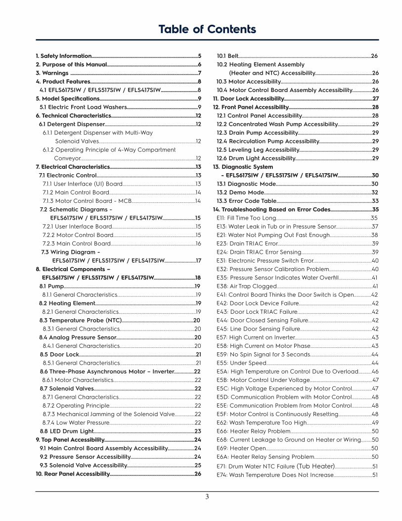
Table of Contents
1. Safety Information....................................................................................52. Purpose of this Manual........................................................................63. Warnings .....................................................................................................74. Product Features.....................................................................................8 4.1 EFLS617SIW / EFLS517SIW / EFLS417SIW.............................85. Model Specifications..............................................................................9 5.1 Electric Front Load Washers........................................................96. Technical Characteristics...................................................................12 6.1 Detergent Dispenser.....................................................................12 6.1.1 Detergent Dispenser with Multi-Way Solenoid Valves.........................................................................12 6.1.2 Operating Principle of 4-Way Compartment Conveyor.......................................................................................127. Electrical Characteristics....................................................................13 7.1 Electronic Control...........................................................................13 7.1.1 User Interface (UI) Board.......................................................13 7.1.2 Main Control Board.................................................................14 7.1.3 Motor Control Board - MCB................................................14 7.2 Schematic Diagrams - EFLS617SIW / EFLS517SIW / EFLS417SIW.........................15 7.2.1 User Interface Board...............................................................15 7.2.2 Motor Control Board..............................................................15 7.2.3 Main Control Board................................................................16 7.3 Wiring Diagram - EFLS617SIW / EFLS517SIW / EFLS417SIW........................178. Electrical Components – EFLS617SIW / EFLS517SIW / EFLS417SIW.................................18 8.1 Pump...................................................................................................19 8.1.1 General Characteristics...........................................................19 8.2 Heating Element............................................................................19 8.2.1 General Characteristics..........................................................19 8.3 Temperature Probe (NTC)......................................................20 8.3.1 General Characteristics........................................................20 8.4 Analog Pressure Sensor...........................................................20 8.4.1 General Characteristics........................................................20 8.5 Door Lock........................................................................................21 8.5.1 General Characteristics.........................................................21 8.6 Three-Phase Asynchronous Motor – Inverter...............22 8.6.1 Motor Characteristics.............................................................22 8.7 Solenoid Valves............................................................................22 8.7.1 General Characteristics.........................................................22 8.7.2 Operating Principle................................................................22 8.7.3 Mechanical Jamming of the Solenoid Valve...............22 8.7.4 Low Water Pressure................................................................22 8.8 LED Drum Light............................................................................239. Top Panel Accessibility.......................................................................24 9.1 Main Control Board Assembly Accessibility....................24 9.2 Pressure Sensor Accessibility................................................24 9.3 Solenoid Valve Accessibility...................................................2510. Rear Panel Accessibility...................................................................26
10.1 Belt....................................................................................................26 10.2 Heating Element Assembly (Heater and NTC) Accessibility...........................................26 10.3 Motor Accessibility.....................................................................26 10.4 Motor Control Board Assembly Accessibility...............2611. Door Lock Accessibility......................................................................2712. Front Panel Accessibility..................................................................28 12.1 Control Panel Accessibility.....................................................28 12.2 Concentrated Wash Pump Accessibility..........................29 12.3 Drain Pump Accessibility........................................................29 12.4 Recirculation Pump Accessibility........................................29 12.5 Leveling Leg Accessibility.......................................................29 12.6 Drum Light Accessibility..........................................................2913. Diagnostic System - EFLS617SIW / EFLS517SIW / EFLS417SIW...........................30 13.1 Diagnostic Mode........................................................................30 13.2 Demo Mode.................................................................................32 13.3 Error Code Table........................................................................3314. Troubleshooting Based on Error Codes.................................35 E11: Fill Time Too Long.......................................................................35 E13: Water Leak in Tub or in Pressure Sensor...........................37 E21: Water Not Pumping Out Fast Enough...............................38 E23: Drain TRIAC Error.......................................................................39 E24: Drain TRIAC Error Sensing.....................................................39 E31: Electronic Pressure Switch Error............................................40 E32: Pressure Sensor Calibration Problem................................40 E35: Pressure Sensor Indicates Water Overfill.........................41 E38: Air Trap Clogged........................................................................41 E41: Control Board Thinks the Door Switch is Open.............42 E42: Door Lock Device Failure.......................................................42 E43: Door Lock TRIAC Failure........................................................42 E44: Door Closed Sensing Failure................................................42 E45: Line Door Sensing Failure......................................................42 E57: High Current on Inverter..........................................................43 E58: High Current on Motor Phase..............................................43 E59: No Spin Signal for 3 Seconds..............................................44 E55: Under Speed...............................................................................44 E5A: High Temperature on Control Due to Overload..........46 E5B: Motor Control Under Voltage...............................................47 E5C: High Voltage Experienced by Motor Control...............47 E5D: Communication Problem with Motor Control...............48 E5E: Communication Problem from Motor Control...............48 E5F: Motor Control is Continuously Resetting.........................48 E62: Wash Temperature Too High.................................................49 E66: Heater Relay Problem.............................................................50 E68: Current Leakage to Ground on Heater or Wiring........50 E69: Heater Open...............................................................................50 E6A: Heater Relay Sensing Problem...........................................50
E71: Drum Water NTC Failure (Tub Heater)............................51 E74: Wash Temperature Does Not Increase.............................51

4
E84: Recirculation Pump TRIAC Series.......................................52 E85: Recirculation Pump TRIAC.....................................................52 E83: Wrong Selector Reading........................................................53 E86: Incorrect User Interface Selection Table.........................53 E87: User Interface Micro-Controller Fault................................53 E91: Communication Error User Interface to Control Board...............................................................................53 E92: User Interface_Main Board Communications Error..............................................................53 E93: Console or Main Board Control Problem.......................54 E94: Main Board Control Problem...............................................54 E97: Console or Main Board Control Problem........................54 E98: Console Control Problem.......................................................54 E9C: User Interface Configuration Problem.............................55 E9E: Key Stuck or Contaminated...................................................55 EH1: Frequency of Power Out of Limits.......................................56 EH2: Supply Voltage Too High......................................................56 EH3: Supply Voltage Too Low........................................................56 EHE: Control Relay Fault...................................................................56 EHF: Control Relay Sense Fault.....................................................56 EF2: Too Much Soap or Wrong Type...........................................57 EF5: Load Unbalanced......................................................................57 EF6: Control Reset................................................................................58 EF9: Hot Valve Warning....................................................................58

5
Read the entire Manual before attempting to service this product. Pay attention to all Warnings, Cautions, Notes and Important information. Failure to do so could result in serious personal injury and / or equipment damage.
DEFINITIONS
WARNING
Indicates a hazardous situation which, if not avoided, could result in death or serious injury.
CAUTION
Used with the safety alert symbol, indicates a hazardous situation which, if not avoided, could result in minor or moderate injury.
NOTE
Used to address practices not related to personal injury.
IMPORTANT
Information that requires special attention from the user.
1. Safety Information

6
2. Purpose of this Manual
The purpose of this Manual is to provide information regarding repair procedures of Washer fitted with the Electronic Control System. This Manual is intended for the use of Service Engineers of Electrolux.
The Manual includes the following topics:
• Product Features, Model Specifications
• Electrical Characteristics and Specifications
• Accessibility of the Electrical and Mechanical Components
• Diagnostics Systems
• Error Codes and Troubleshooting
7
3. Warnings
• Any work on Electrical Appliances must be carried out by a qualified professional.
• Confirm that the Power System is operational before working on the Appliance.
• Check that the Appliance is restored to its original safety condition after the operation is complete.
• Take the plug out of the socket to disconnect the power supply before you access internal components. This platform is not fitted with an ON / OFF switch.
• The Sensors located on the display board could be at a potential of 220 Volts (If applicable).
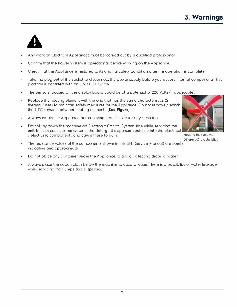
• Replace the heating element with the one that has the same characteristics (2 thermal fuses) to maintain safety measures for the Appliance. Do not remove / switch the NTC sensors between heating elements (See Figure).
• Always empty the Appliance before laying it on its side for any servicing.
• Do not lay down the machine on Electronic Control System side while servicing the unit. In such cases, some water in the detergent dispenser could sip into the electrical / electronic components and cause these to burn.
• The resistance values of the components shown in this SM (Service Manual) are purely indicative and approximate.
• Do not place any container under the Appliance to avoid collecting drops of water.
• Always place the cotton cloth below the machine to absorb water. There is a possibility of water leakage while servicing the Pumps and Dispenser.
Heating Element with Different Characteristics

8
4. Product Features
4.1 EFLS617SIW / EFLS517SIW / EFLS417SIW

9
5. Model Specifications
Description EFLS617SIW EFLS517SIW EFLS417SIW
Total Capacity D.O.E. 4.4 Cu. Ft. 4.3 Cu. Ft. 4.3 Cu. Ft.
Washer Drum Interior Stainless Steel Stainless Steel Stainless Steel
Lifetime Warranty Tub Yes Yes Yes
Interior Light Yes Yes No
Door Trim Chrome Chrome White
Vibration Control System Yes Yes Yes
Advanced Rinse Technology Yes Yes Yes
TimeWise® Technology Yes Yes Yes
Ready Clean™ No No No
Ready Steam™ Perfect Steam Perfect Steam No
Extra Rinse Option Yes Yes Yes
Extended Refresh option Yes Yes No
Perfect Steam option Yes Yes No
StainSoak option Yes No No
StainTreat II No Yes No
StainTreat No No Yes
Sanitize option Yes Yes No
Stay-Fresh™ Door Seal Yes Yes Yes
Temperature Control Automatic Automatic Automatic
Water Level Adjustments Automatic Automatic Automatic
Auto Prewash Detergent Dispenser Yes Yes Yes
Auto Bleach Dispenser Yes Yes Yes
Auto Detergent Dispenser Yes Yes Yes
Auto Fabric Softener Dispenser Yes Yes Yes
Time Remaining Display Yes Yes Yes
Cycle Status Display Yes Yes Yes
Cycle Signal Chime + LED Chime Chime
Cycle Signal "ON / OFF": Yes Yes Yes
Cycle Signal Volume Control No No No
Mute / Unmute Yes Yes Yes
Door Lock Indicator Display Yes Yes Yes
Control Lock Yes Yes Yes
Stay Put Door Yes Yes Yes
Start / Pause / Cancel Buttons Yes Yes Yes
Energy Saver Option (Leaf Icon) Yes Yes Yes
Delay Start Yes (Up to 16 Hr) Yes (Up to 16 Hr) Yes (Up to 16 Hr)
Integral Water Heater Yes, 1000 Watts Yes, 1000 Watts No
Tumble Speed (RPM) Variable Variable Variable
5.1 Electric Front Load Washers
10
Description EFLS617SIW EFLS517SIW EFLS417SIW
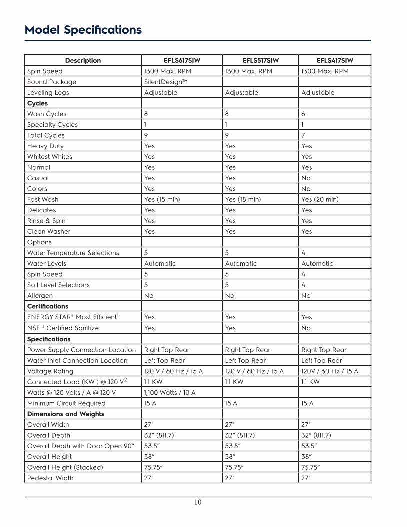
Spin Speed 1300 Max. RPM 1300 Max. RPM 1300 Max. RPM
Sound Package SilentDesign™
Leveling Legs Adjustable Adjustable Adjustable
Cycles
Wash Cycles 8 8 6
Specialty Cycles 1 1 1
Total Cycles 9 9 7
Heavy Duty Yes Yes Yes
Whitest Whites Yes Yes Yes
Normal Yes Yes Yes
Casual Yes Yes No
Colors Yes Yes No
Fast Wash Yes (15 min) Yes (18 min) Yes (20 min)
Delicates Yes Yes Yes
Rinse & Spin Yes Yes Yes
Clean Washer Yes Yes Yes
Options
Water Temperature Selections 5 5 4
Water Levels Automatic Automatic Automatic
Spin Speed 5 5 4
Soil Level Selections 5 5 4
Allergen No No No
Certifications
ENERGY STAR® Most Efficient1 Yes Yes Yes
NSF ® Certified Sanitize Yes Yes No
Specifications
Power Supply Connection Location Right Top Rear Right Top Rear Right Top Rear
Water Inlet Connection Location Left Top Rear Left Top Rear Left Top Rear
Voltage Rating 120 V / 60 Hz / 15 A 120 V / 60 Hz / 15 A 120V / 60 Hz / 15 A
Connected Load (KW ) @ 120 V2 1.1 KW 1.1 KW 1.1 KW
Watts @ 120 Volts / A @ 120 V 1,100 Watts / 10 A
Minimum Circuit Required 15 A 15 A 15 A
Dimensions and Weights
Overall Width 27" 27" 27"
Overall Depth 32” (811.7) 32” (811.7) 32” (811.7)
Overall Depth with Door Open 90° 53.5” 53.5” 53.5”
Overall Height 38” 38” 38”
Overall Height (Stacked) 75.75” 75.75” 75.75”
Pedestal Width 27" 27" 27"
Model Specifications

11
Description EFLS617SIW EFLS517SIW EFLS417SIW
Pedestal Depth 26 - 1/2" 26 - 1/2” 26 - 1/2”
Pedestal Depth with Drawer Extended
42 - 1/2" 42 - 1/2” 42 - 1/2”
Pedestal Height 15.25” 15.25” 15.25”
Shipping Weight (Approx.) 222.0 Lbs 222.0 Lbs 222.0 Lbs
NOTE
1. Recognized as the Most Efficient of ENERGY STAR® in 2016.
2. For use on adequately wired 120 V dedicated circuit having 2-wire service with a separate ground wire. Appliance must be grounded for safe operation.
Model Specifications
12
6.1 Detergent Dispenser
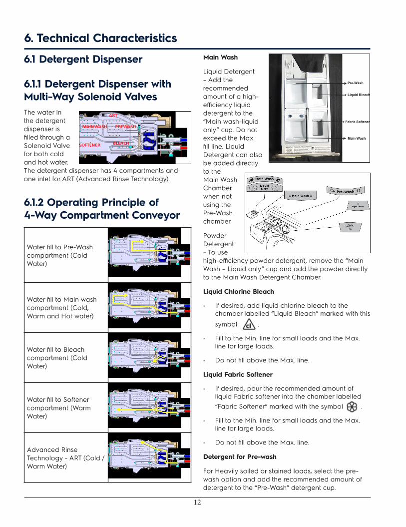
6.1.1 Detergent Dispenser with Multi-Way Solenoid Valves The water in the detergent dispenser is filled through a Solenoid Valve for both cold and hot water. The detergent dispenser has 4 compartments and one inlet for ART (Advanced Rinse Technology).
6.1.2 Operating Principle of 4-Way Compartment Conveyor
Water fill to Pre-Wash compartment (Cold Water)
Water fill to Main wash compartment (Cold, Warm and Hot water)
Water fill to Bleach compartment (Cold Water)
Water fill to Softener compartment (Warm Water)
Advanced Rinse Technology - ART (Cold / Warm Water)
6. Technical CharacteristicsMain Wash
Liquid Detergent – Add the recommended amount of a high-efficiency liquid detergent to the “Main wash-liquid only” cup. Do not exceed the Max. fill line. Liquid Detergent can also be added directly to the Main Wash Chamber when not using the Pre-Wash chamber.
Powder Detergent – To use high-efficiency powder detergent, remove the “Main Wash – Liquid only” cup and add the powder directly to the Main Wash Detergent Chamber.
Liquid Chlorine Bleach
• If desired, add liquid chlorine bleach to the chamber labelled “Liquid Bleach” marked with this
symbol .
• Fill to the Min. line for small loads and the Max. line for large loads.
• Do not fill above the Max. line.
Liquid Fabric Softener
• If desired, pour the recommended amount of liquid Fabric softener into the chamber labelled “Fabric Softener” marked with the symbol .
• Fill to the Min. line for small loads and the Max. line for large loads.
• Do not fill above the Max. line.
Detergent for Pre-wash
For Heavily soiled or stained loads, select the pre-wash option and add the recommended amount of detergent to the “Pre-Wash” detergent cup.
Pre-Wash
Liquid Bleach
Main Wash
Fabric Softener

13
7. Electrical Characteristics
7.1 Electronic ControlThe Electronic Control is made up of the following:
1. User Interface (UI) Board
2. Main Control Board (Positioned inside the machine on the right side near to the Rear Panel)
3. Motor Control Board (Positioned at the bottom left of the Appliance seen from the rear)
7.1.1 User Interface (UI) BoardThe User Interface (UI) Board contains: the selector dial to select the washing programme, the LCD display to display the programme, status, time and so on information. Buttons are available to adjust the following: the washing temperature, the spin speed, to select an option, the degree of drying and lastly the start / pause button to pause or start a programme, while cancel button acts as OFF.
It is possible to select the programmes by turning the selector. The options can be selected by pressing / touching the buttons. The start / pause button is used to start the machine or pause it. The buzzer - where featured, is powered by the User Interface (UI) Board.
User Interface (UI) Board – EFLS617SIW
14
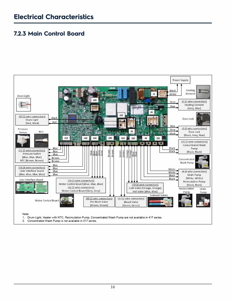
7.1.2 Main Control Board The Main Control Board supplies the power supply voltage to the Motor control and User Interface (UI) Board and all other electrical components.
The commands acquired by the User Interface Board (by turning the selector, selecting an option and so on) are sent to the Main Control Board, which powers all the electrical components (Solenoid Valve, Drain Pump, Heating Element Assembly, Door Lock, Motor Control Board and the Display Board).
1. It controls the level of water via the analog Pressure Sensor.
2. It controls and monitors the status of the door.
3. It controls the temperature of the wash water via NTC probe inserted in the heating element.
4. It controls the voltage and frequency of the power supply and ensures they are close to the rated ones.
5. It controls the flow of water through the Solenoid Valve.
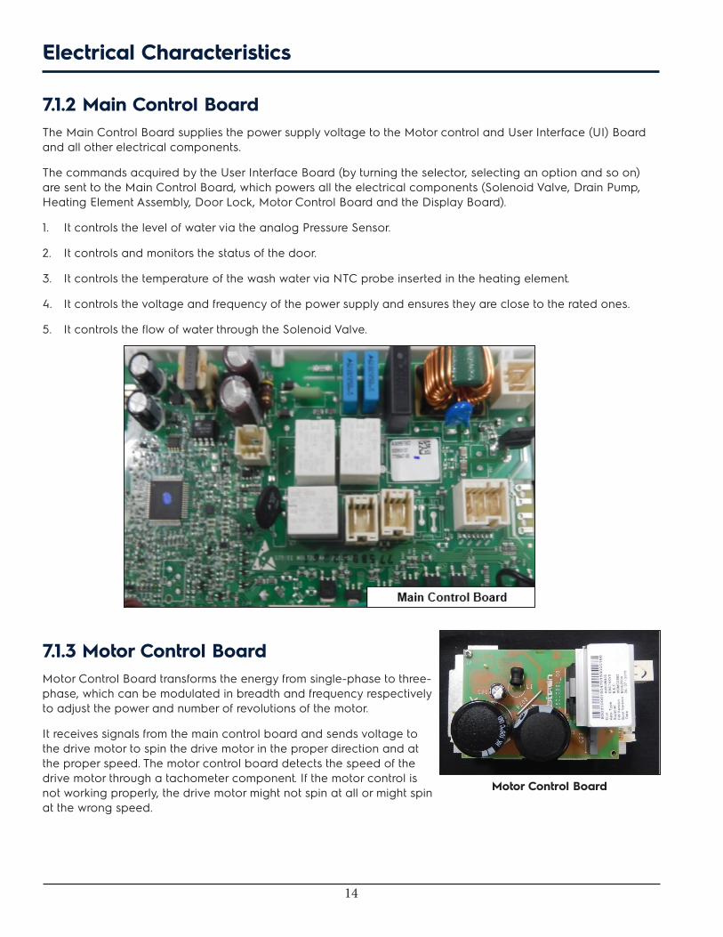
7.1.3 Motor Control BoardMotor Control Board transforms the energy from single-phase to three-phase, which can be modulated in breadth and frequency respectively to adjust the power and number of revolutions of the motor.
It receives signals from the main control board and sends voltage to the drive motor to spin the drive motor in the proper direction and at the proper speed. The motor control board detects the speed of the drive motor through a tachometer component. If the motor control is not working properly, the drive motor might not spin at all or might spin at the wrong speed.
Electrical Characteristics
Motor Control Board

15
7.2 Schematic Diagrams - EFLS617SIW / EFLS517SIW / EFLS417SIW
7.2.1 User Interface Board
7.2.2 Motor Control Board
Electrical Characteristics
16
7.2.3 Main Control Board
Electrical Characteristics

17
7.3 Wiring Diagram - EFLS617SIW / EFLS517SIW / EFLS417SIW
Electrical Characteristics
18
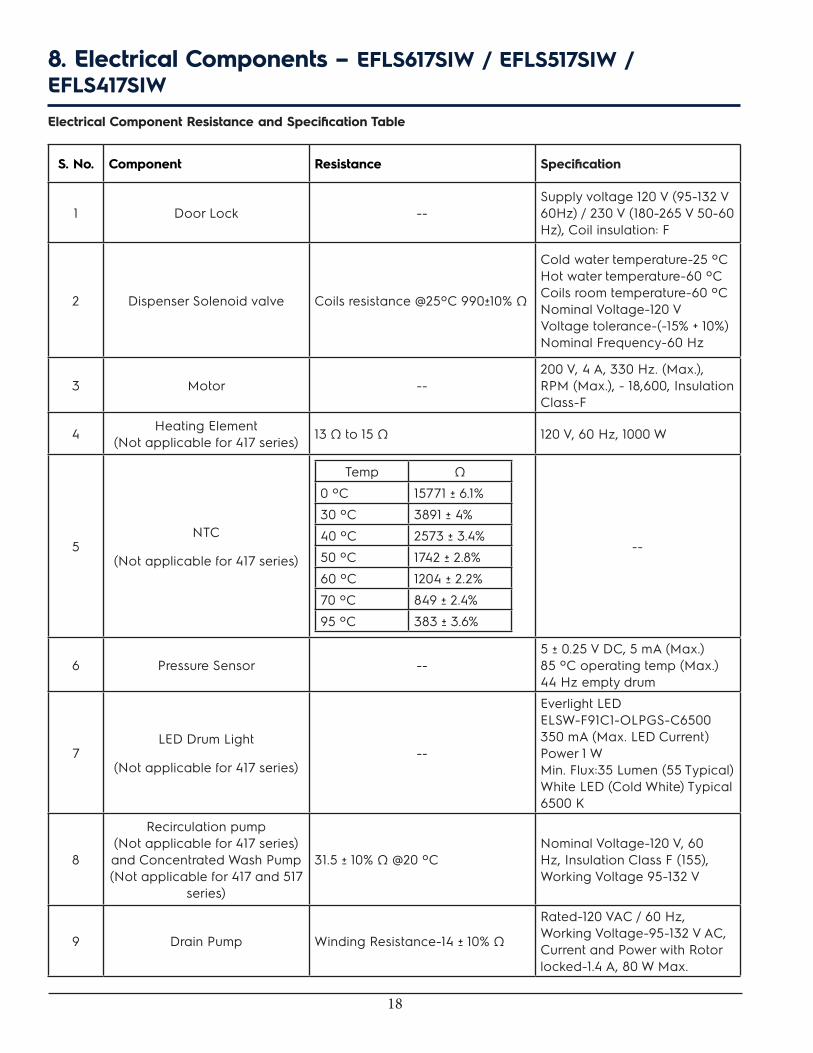
8. Electrical Components – EFLS617SIW / EFLS517SIW / EFLS417SIWElectrical Component Resistance and Specification Table
S. No. Component Resistance Specification
1 Door Lock --Supply voltage 120 V (95-132 V 60Hz) / 230 V (180-265 V 50-60 Hz), Coil insulation: F
2 Dispenser Solenoid valve Coils resistance @25ºC 990±10% Ω
Cold water temperature-25 ºC Hot water temperature-60 ºC Coils room temperature-60 ºC Nominal Voltage-120 V Voltage tolerance-(-15% + 10%) Nominal Frequency-60 Hz
3 Motor --200 V, 4 A, 330 Hz. (Max.), RPM (Max.), - 18,600, Insulation Class-F
4 Heating Element (Not applicable for 417 series) 13 Ω to 15 Ω 120 V, 60 Hz, 1000 W
5NTC
(Not applicable for 417 series)
Temp Ω
0 ºC 15771 ± 6.1%
30 ºC 3891 ± 4%
40 ºC 2573 ± 3.4%
50 ºC 1742 ± 2.8%
60 ºC 1204 ± 2.2%
70 ºC 849 ± 2.4%
95 ºC 383 ± 3.6%
--
6 Pressure Sensor --5 ± 0.25 V DC, 5 mA (Max.) 85 ºC operating temp (Max.) 44 Hz empty drum
7LED Drum Light
(Not applicable for 417 series)--
Everlight LED ELSW-F91C1-OLPGS-C6500 350 mA (Max. LED Current) Power 1 W Min. Flux:35 Lumen (55 Typical) White LED (Cold White) Typical 6500 K
8
Recirculation pump (Not applicable for 417 series) and Concentrated Wash Pump (Not applicable for 417 and 517
series)
31.5 ± 10% Ω @20 ºCNominal Voltage-120 V, 60 Hz, Insulation Class F (155), Working Voltage 95-132 V
9 Drain Pump Winding Resistance-14 ± 10% Ω
Rated-120 VAC / 60 Hz, Working Voltage-95-132 V AC, Current and Power with Rotor locked-1.4 A, 80 W Max.
19
WARNING
When replacing the Pump, please refer to the code shown in the list of spare parts relating to the Appliance.
8.1 PumpThere are more than one pumps used for this model:
• Drain Pump
• Recirculation Pump
• Concentrated Wash Pump
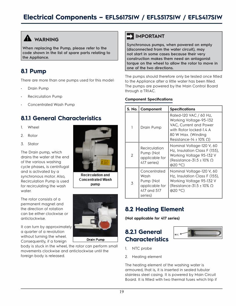
8.1.1 General Characteristics1. Wheel
2. Rotor
3. Stator
The Drain pump, which drains the water at the end of the various washing cycle phases, is centrifugal and is activated by a synchronous motor. Also, Recirculation Pump is used for recirculating the wash water.
The rotor consists of a permanent magnet and the direction of rotation can be either clockwise or anticlockwise.
It can turn by approximately a quarter of a revolution without turning the wheel. Consequently, if a foreign body is stuck in the wheel, the rotor can perform small movements clockwise and anticlockwise until the foreign body is released.
IMPORTANT
Synchronous pumps, when powered on empty (disconnected from the water circuit), may not start in some cases because their very construction makes them need an antagonist torque on the wheel to allow the rotor to move in one of the two directions.
The pumps should therefore only be tested once fitted to the Appliance after a little water has been filled. The pumps are powered by the Main Control Board through a TRIAC.
Component Specifications
S. No. Component Specifications
1 Drain Pump
Rated-120 VAC / 60 Hz, Working Voltage-95-132 VAC, Current and Power with Rotor locked-1.4 A 80 W Max. (Winding Resistance-14 ± 10% Ω)
2
Recirculation Pump (Not applicable for 417 series)
Nominal Voltage-120 V, 60 Hz, Insulation Class F (155), Working Voltage 95-132 V (Resistance-31.5 ± 10% Ω @20 ºC)
3
Concentrated Wash Pump (Not applicable for 417 and 517 series)
Nominal Voltage-120 V, 60 Hz, Insulation Class F (155), Working Voltage 95-132 V (Resistance-31.5 ± 10% Ω @20 ºC)
8.2 Heating Element(Not applicable for 417 series)
8.2.1 General Characteristics1. NTC probe
2. Heating element
The heating element of the washing water is armoured, that is, it is inserted in sealed tubular stainless steel casing. It is powered by Main Circuit Board. It is fitted with two thermal fuses which trip if
Electrical Components – EFLS617SIW / EFLS517SIW / EFLS417SIW
20
the temperature of the heating element exceeds the values for which they were calibrated.
WARNING
• When replacing the heating element, please refer to the code shown in the list of spare parts related to the Appliance.
• It is strictly forbidden to tamper with the heating element in any way (For example, replace the NTC probe, and so on).
Component Specifications
S. No. Component Specifications
1 Heating Element
120 V, 60 Hz, 1000 W (Resistance-13 Ω to 15 Ω)
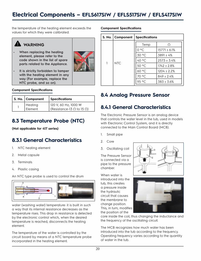
8.3 Temperature Probe (NTC)(Not applicable for 417 series)
8.3.1 General Characteristics1. NTC heating element
2. Metal capsule
3. Terminals
4. Plastic casing
An NTC type probe is used to control the drum
water (washing water) temperature: it is built in such a way that its internal resistance decreases as the temperature rises. This drop in resistance is detected by the electronic control which, when the desired temperature is reached, disconnects the heating element.
The temperature of the water is controlled by the circuit board by means of a NTC temperature probe incorporated in the heating element.
Component Specifications
S. No. Component Specifications
1 NTC
Temp Ω
0 ºC 15771 ± 6.1%
30 ºC 3891 ± 4%
40 ºC 2573 ± 3.4%
50 ºC 1742 ± 2.8%
60 ºC 1204 ± 2.2%
70 ºC 849 ± 2.4%
95 ºC 383 ± 3.6%
8.4 Analog Pressure Sensor
8.4.1 General Characteristics The Electronic Pressure Sensor is an analog device that controls the water level in the tub, used in models with Electronic Control System, and it is directly connected to the Main Control Board (MCB).
1. Small pipe
2. Core
3. Oscillating coil
The Pressure Sensor is connected via a pipe to the pressure chamber.
When water is introduced into the tub, this creates a pressure inside the hydraulic circuit that causes the membrane to change position. This, in turn, modifies the position of the core inside the coil, thus changing the inductance and the frequency of the oscillating circuit.
The MCB recognizes how much water has been introduced into the tub according to the frequency. Operating frequency varies according to the quantity of water in the tub.
Electrical Components – EFLS617SIW / EFLS517SIW / EFLS417SIW
21
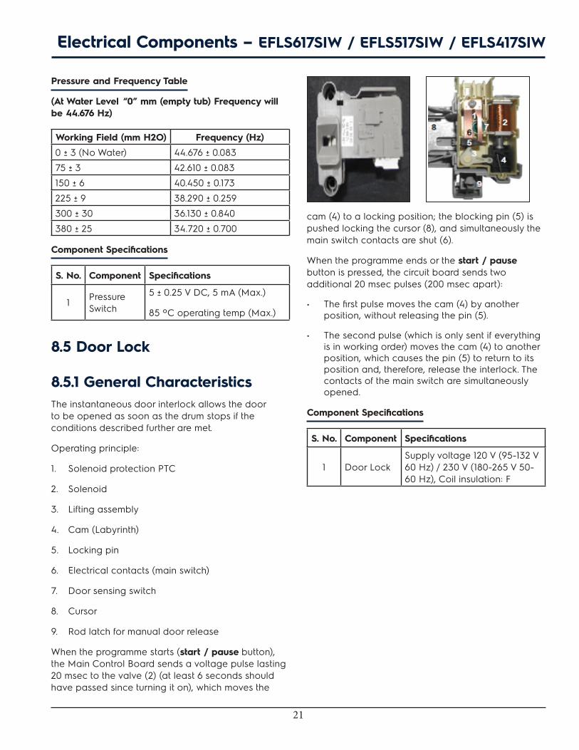
Pressure and Frequency Table
(At Water Level “0” mm (empty tub) Frequency will be 44.676 Hz)
Working Field (mm H2O) Frequency (Hz)
0 ± 3 (No Water) 44.676 ± 0.083
75 ± 3 42.610 ± 0.083
150 ± 6 40.450 ± 0.173
225 ± 9 38.290 ± 0.259
300 ± 30 36.130 ± 0.840
380 ± 25 34.720 ± 0.700
Component Specifications
S. No. Component Specifications
1 Pressure Switch
5 ± 0.25 V DC, 5 mA (Max.)
85 ºC operating temp (Max.)
8.5 Door Lock
8.5.1 General CharacteristicsThe instantaneous door interlock allows the door to be opened as soon as the drum stops if the conditions described further are met.
Operating principle:
1. Solenoid protection PTC
2. Solenoid
3. Lifting assembly
4. Cam (Labyrinth)
5. Locking pin
6. Electrical contacts (main switch)
7. Door sensing switch
8. Cursor
9. Rod latch for manual door release
When the programme starts (start / pause button), the Main Control Board sends a voltage pulse lasting 20 msec to the valve (2) (at least 6 seconds should have passed since turning it on), which moves the
cam (4) to a locking position; the blocking pin (5) is pushed locking the cursor (8), and simultaneously the main switch contacts are shut (6).
When the programme ends or the start / pause button is pressed, the circuit board sends two additional 20 msec pulses (200 msec apart):
• The first pulse moves the cam (4) by another position, without releasing the pin (5).
• The second pulse (which is only sent if everything is in working order) moves the cam (4) to another position, which causes the pin (5) to return to its position and, therefore, release the interlock. The contacts of the main switch are simultaneously opened.
Component Specifications
S. No. Component Specifications
1 Door LockSupply voltage 120 V (95-132 V 60 Hz) / 230 V (180-265 V 50-60 Hz), Coil insulation: F
Electrical Components – EFLS617SIW / EFLS517SIW / EFLS417SIW
22
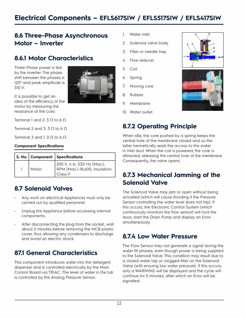
8.6 Three-Phase Asynchronous Motor – Inverter
8.6.1 Motor CharacteristicsThree-Phase power is fed by the inverter. The phase shift between the phases is 120° and peak amplitude is 310 V.
It is possible to get an idea of the efficiency of the motor by measuring the resistance of the coils:
Terminal 1 and 2: 3 Ω to 6 Ω
Terminal 2 and 3: 3 Ω to 6 Ω
Terminal 3 and 1: 3 Ω to 6 Ω
Component Specifications
S. No. Component Specifications
1 Motor200 V, 4 A, 330 Hz (Max.), RPM (Max.)-18,600, Insulation Class-F
8.7 Solenoid Valves• Any work on electrical Appliances must only be
carried out by qualified personnel.
• Unplug the Appliance before accessing internal components.
• After disconnecting the plug from the socket, wait about 2 minutes before removing the MCB plastic cover, thus allowing any condensers to discharge and avoid an electric shock.
87.1 General CharacteristicsThis component introduces water into the detergent dispenser and is controlled electrically by the Main Control Board via TRIAC. The level of water in the tub is controlled by the Analog Pressure Sensor.
1. Water inlet
2. Solenoid valve body
3. Filter or needle trap
4. Flow reducer
5. Coil
6. Spring
7. Moving core
8. Rubber
9. Membrane
10. Water outlet
8.7.2 Operating PrincipleWhen idle, the core pushed by a spring keeps the central hole of the membrane closed and so the latter hermetically seals the access to the water in inlet duct. When the coil is powered, the core is attracted, releasing the central hole of the membrane. Consequently, the valve opens.
8.7.3 Mechanical Jamming of the Solenoid Valve The Solenoid Valve may jam or open without being actuated (which will cause flooding if the Pressure Sensor controlling the water level does not trip). If this occurs, the Electronic Control System (which continuously monitors the flow sensor) will lock the door, start the Drain Pump and display an Error simultaneously.
8.7.4 Low Water Pressure The Flow Sensor may not generate a signal during the water fill phases, even though power is being supplied to the Solenoid Valve. This condition may result due to a closed water tap or clogged filter on the Solenoid Valve (with ensuing low water pressure). If this occurs, only a WARNING will be displayed and the cycle will continue for 5 minutes, after which an Error will be signalled.
Electrical Components – EFLS617SIW / EFLS517SIW / EFLS417SIW

23
Component Specifications
S. No. Component Specifications
1 Dispenser Solenoid valve
Cold water temperature-25 ºC
Hot water temperature-60 ºC
Coils room temperature-60 ºC
Nominal voltage-120 V
Voltage tolerance- (-15% + 10%)
Nominal frequency-60 Hz
(Coils resistance @25 ºC 990 ± 10% Ω)
8.8 LED Drum Light(Not applicable for 417 series)
The high power LED wall Washers are high power LED lights that are used for decorative lighting and highlight, or wash walls.
Component Specifications
S. No. Component Specifications
1 LED Drum Light
Everlight LED
ELSW-F91C1-OLPGS-C6500
350 mA (Max. LED Current)
Power 1 W
Min. Flux: 35 Lumen (55 Typical)
White LED (Cold White) Typical 6500 K
Electrical Components – EFLS617SIW / EFLS517SIW / EFLS417SIW

24
9. Top Panel Accessibility
Step: 1
Loosen the screws (See Fig. 1), and slide the Top Panel backwards until it gets unlocked (See Fig. 2). Now lift the Top Panel (See Fig. 3).
From the Work Top we can access:
1. Main Control Board
2. Pressure Sensor
3. Solenoid Valve
9.1 Main Control Board Assembly AccessibilityStep: 1
Loosen up the screw (See Fig.1), slide the board as shown (See Fig. 2), and detach the connectors (See Fig. 3).
Step: 2
Release the snaps (See Fig. 4), detach the remaining connectors (See Fig. 5), and take out the Main Control Board Assembly (See Fig. 6).
9.2 Pressure Sensor AccessibilityStep: 1
Rotate the Pressure Sensor in anticlockwise direction from the side panel (See Fig. 1), detach the connector (See Fig. 2), remove the tube (See Fig. 3), and take out the Pressure Sensor (See Fig. 4).
25
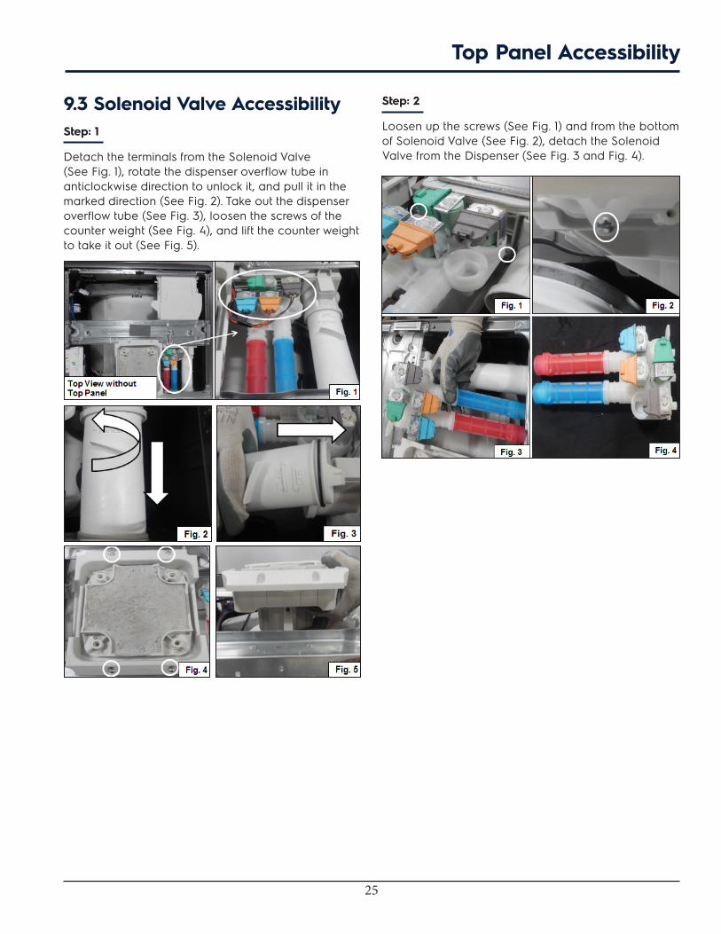
9.3 Solenoid Valve AccessibilityStep: 1
Detach the terminals from the Solenoid Valve (See Fig. 1), rotate the dispenser overflow tube in anticlockwise direction to unlock it, and pull it in the marked direction (See Fig. 2). Take out the dispenser overflow tube (See Fig. 3), loosen the screws of the counter weight (See Fig. 4), and lift the counter weight to take it out (See Fig. 5).
Step: 2
Loosen up the screws (See Fig. 1) and from the bottom of Solenoid Valve (See Fig. 2), detach the Solenoid Valve from the Dispenser (See Fig. 3 and Fig. 4).
Top Panel Accessibility

26
10. Rear Panel Accessibility
Step: 1
Loosen the screws to remove the Rear Access Panel (See Fig. 1).
From the Rear Panel we can access:
1. Belt
2. Heating Element Assembly (Heater and NTC)
3. Motor Control Board Assembly
4. Motor
10.1 BeltPull out Belt by rotating pulley in clockwise direction (See Fig. 1). Belt is shown in figure.
10.2 Heating Element Assembly (Heater and NTC) Accessibility(Not applicable for 417 series)
Step: 1
Detach the connectors of Heater Assembly (See Fig. 1), loosen the nut (See Fig. 2), pull the heater assembly from the tub (See Fig. 3), and pull out the NTC from the heater assembly (See Fig. 4). Heater Assembly is shown in Fig. 5.
10.3 Motor AccessibilityStep: 1
Detach the connector (See Fig. 1), remove the wire clip (See Fig. 2), loosen the bolts (See Fig. 3), and take out the Motor from the machine as shown (See Fig. 4).
10.4 Motor Control Board Assembly AccessibilityStep: 1
Loosen the screw from inside the Rear Panel (See Fig.1), and the one from outside of the rear panel (See Fig. 2). Release the snaps from the upper side (See Fig. 3) and lower side (See Fig.4) of the Motor Control Assembly for opening the Motor Control Board box. Detach the connectors (See Fig. 5). Motor Control Board Assembly is shown in figure.

27
11. Door Lock Accessibility
Loosen the screws of Door Lock which is fixed to the Front Panel (See Fig.1). Detach the connectors (Fig. 2), and loosen the screws as shown (See Fig. 3). Door Lock is removed from the Front Panel as shown (See Fig.4).

28
12. Front Panel Accessibility
Step: 1
Release the bellow clamp and loosen the Bellow as shown (See Fig. 1, 2, and 3). Pull out the Dispenser as shown (See Fig. 4) and loosen the screws as shown (See Fig. 5).
Step: 2
Loosen the 3 screws at the top (See Fig. 1) and 4 screws at the bottom (See Fig. 2) of Front Panel. Lift the Front panel until it is unlocked from the Side Panel (See Fig. 3) and detach the connector (See Fig. 4 and 5). Front Panel with User Interface Board Assembly is shown in figure.
From the Front Panel we can access:
1. Control Panel
12.1 Control Panel AccessibilityLoosen the screws, release the snaps (See Fig. 1), and loosen the remaining screws (See Fig. 2) to remove the User Interface (UI) Board Assembly (See Fig. 3).
After Front Panel removal, the following components can be accessed from the Washer:
1. Concentrated Wash Pump
2. Drain Pump
3. Recirculation Pump

29
12.2 Concentrated Wash Pump Accessibility(Not applicable for 417 and 517 series)
Step: 1
Remove the circlip (See Fig. 1), loosen the screw (See Fig. 2), then detach the connector (See Fig. 3) to separate the Concentrated Wash Pump
12.4 Recirculation Pump Accessibility(Not applicable for 417 series)
Remove the circlip (See Fig. 1), loosen the screw (See Fig. 2), and detach the connector (See Fig. 3) to separate the Recirculation Pump.
12.3 Drain Pump AccessibilityRemove the circlip (See Fig. 1), loosen the screw (See Fig. 2), then detach the connector (See Fig. 3) and release the snaps (See Fig. 4) to separate the Drain Pump.
12.5 Leveling Leg AccessibilityIncline the Dryer as shown (Fig. 1). Loosen the Leveling Leg with the help of a wrench (Fig. 2). Similarly, remove the rear side Leveling Leg by inclining the Washer in other direction.
12.6 Drum Light Accessibility(Not applicable for 417 series) Remove the Drum Light from the Bellow as shown in (Fig. 1). Remove the splice (Fig. 2) to take out Drum Light from the Washer.
Front Panel Accessibility
30
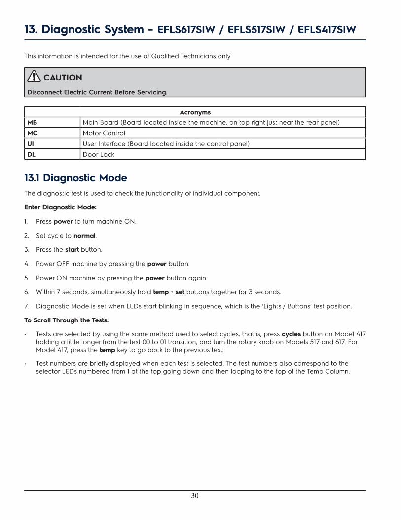
13. Diagnostic System - EFLS617SIW / EFLS517SIW / EFLS417SIW
This information is intended for the use of Qualified Technicians only.
CAUTION
Disconnect Electric Current Before Servicing.
Acronyms
MB Main Board (Board located inside the machine, on top right just near the rear panel)
MC Motor Control
UI User Interface (Board located inside the control panel)
DL Door Lock
13.1 Diagnostic ModeThe diagnostic test is used to check the functionality of individual component.
Enter Diagnostic Mode:
1. Press power to turn machine ON.
2. Set cycle to normal.
3. Press the start button.
4. Power OFF machine by pressing the power button.
5. Power ON machine by pressing the power button again.
6. Within 7 seconds, simultaneously hold temp + set buttons together for 3 seconds.
7. Diagnostic Mode is set when LEDs start blinking in sequence, which is the ‘Lights / Buttons’ test position.
To Scroll Through the Tests:
• Tests are selected by using the same method used to select cycles, that is, press cycles button on Model 417 holding a little longer from the test 00 to 01 transition, and turn the rotary knob on Models 517 and 617. For Model 417, press the temp key to go back to the previous test.
• Test numbers are briefly displayed when each test is selected. The test numbers also correspond to the selector LEDs numbered from 1 at the top going down and then looping to the top of the Temp Column.

31
Test # (Model) Test Name Components under
test Test conditions Displayed feedback
‘00 Lights / Buttons Test LEDs, LCD, touch buttons
The display elements and few LEDs cycle ON and OFF in a sequence.
Press LEDs of touch key or press Power button.
‘01 Wash Compartment Door Lock, Hot Valve
Valve stays ON till water level reaches 140 mm and the door remains locked for 5 minutes.*
Water Level
‘02 Bleach Compartment
Door Lock, Bleach Valve
Valve stays ON till water level reaches 140 mm and the door remains locked for 5 minutes.*
Water Level
‘03 Softener Compartment
Door Lock, Cold Valve, Bleach Valve
Valve stays ON till water level reaches 140 mm and the door remains locked for 5 minutes.*
Water Level
‘04 Stain Compartment Door Lock, Pre-wash Valve
Valve stays ON till water level reaches 140 mm and the door remains locked for 5 minutes.*
Water Level
‘05 Door Unlock Drum Light Drum Light turns ON when the door is open. -- --
‘06 Heater and MotorPressure Sensor, Cold Valve, Motor, NTC, Door Lock
Motor moves after machine fills 60 mm of water. Max. duration of the test is 8 minutes.
NTC reading
‘07 (41) Empty None None Display shows n0 for empty test
‘07 (51,61) Recirculation Pump
Recirculation Pump, Pressure Sensor, Cold Valve, Motor, Door Lock, Drum Light
Motor moves after machine fills 140 mm of water and Recirculation Pump turns ON. Max. duration of the test is 8 minutes.
rP
‘08 (41,51) Empty None None Display shows n0 for empty test
‘08 (61) Concentrate Wash Pump
Concentrate Wash Pump, Door Lock, Drum Light
CW Pump turns ON for max. 5 minutes. Need power meter to check for CW Pump working.
Cp
‘09 Drain Pump and Spin
Drain Pump, Motor, Door Lock
Drain Pump turns ON until empty, then motor starts spinning until max. RPM for 30 seconds and the door remains locked for 6 minutes.*
-- --
‘10 All valves ON Door Lock, All Valves
Valves stay ON till water level reaches 140 mm, then the door remains locked for 5 minutes.*
Water Level
‘11 Error History Errors in memory
Errors are displayed in order of history, displaying the most recent first. Pressing Temp + Set keys together clears the history.
E precedes the 2 character error code, alternating through the last 3 errors.
Diagnostic System - EFLS617SIW / EFLS517SIW / EFLS417SIW
32
NOTE
The door is locked in the test step, however, it can change without delay in another test step or on exit from diagnostic mode.
Exit Diagnostic Mode
To return the Washer to normal operation
• Hold the power button for 3 secs when not in ’00’ test (Lights / Buttons), or unplug the unit.
Factory Default Reset
1. Press power button for power ON and wait for 10 seconds.
2. Simultaneously hold soil + option buttons for 3 seconds.
13.2 Demo Mode
WARNING
This information is intended for Qualified Technicians Only.
CAUTION
Disconnect Electric Current Before Servicing.
Demo Mode
The Demo works in two ways: interactive mode and automatic loop.
1. The interactive mode enables the customer to use interface without activating the water and heat. The machine behaviour appears similar to operation. The start option locks the door, the drum light turns ON and the ETR is decreased each second. No water load / drain is executed.
2. If no one interacts with the interface for 3 minutes, or start button has not been pushed, the machine goes into an automatic loop instead, simulating the cycle execution is only on display. This automatic loop cycle continues until it is interrupted by the user interface and it goes back to the interactive mode.
Diagnostic System - EFLS617SIW / EFLS517SIW / EFLS417SIW
Enter Demo Mode:
1. Press power button to switch ON the machine via Power button;
2. Turn the selector to the 6th position from the top clockwise;
3. Simultaneously hold temp and set buttons for 3 seconds;
4. The message “dn” blinks 3 times on cycle time digits;
5. When no acknowledgement is received, switch the machine OFF and repeat sequence from the beginning.
Every time the machine is switched ON, Demo mode is automatically recalled; this occurrence is signalled at the start-up by the text “dM” blinks 3 times on cycle time digits. Unplugging the unit will not clear the DEMO mode.
Exit Demo Mode:
1. Redo the enter demo mode sequence of actions described above or go to the next step.
2. Press the reset combination (soil + options buttons) anytime.
3. If the action is acknowledged, the machine reboots in normal mode.
SAFETY WARNING
If power is removed during this test, the door can be opened. To prevent injury, do not put your hands inside when the tub is rotating.

33
13.3 Error Code Table
Error Code Table
S. No. Error Code Fault Condition UI Notification Page No
1 E11 Fill Time Too Long YES 35
2 E13 Water Leak in Tub or in Pressure Sensor NO 37
3 E21 Water Not Pumping Out Fast Enough YES 38
4 E23 Drain TRIAC Error NO 39
5 E24 Drain TRIAC Error Sensing NO 39
6 E31 Electronic Pressure Switch Error NO 40
7 E32 Pressure Sensor Calibration Problem NO 40
8 E35 Pressure Sensor Indicates Water Overfill NO 41
9 E38 Air Trap Clogged NO 41
10 E41 Control Board Thinks the Door Switch is Open YES 42
11 E42 Door Lock Device Failure NO 42
12 E43 Door Lock TRIAC Failure NO 42
13 E44 Door Closed Sensing Failure NO 42
14 E45 Line Door Sensing Failure NO 42
15 E55 Under Speed NO 44
16 E57 High Current on Inverter NO 43
17 E58 High Current on Motor Phase NO 48
18 E59 No Spin Signal for 3 Seconds NO 44
19 E5A High Temperature on Control Due to Overload NO 46
20 E5B Motor Control Under Voltage NO 47
21 E5C High Voltage Experienced by Motor Control NO 47
22 E5D Communication Problem with Motor Control NO 48
23 E5E Communication Problem from Motor Control NO 48
24 E5F Motor Control is Continuously Resetting NO 48
25 E62 Wash Temperature Too High NO 49
26 E66 Heater Relay Problem NO 50
27 E68 Current Leakage to Ground on Heater or Wiring NO 50
28 E69 Heater Open NO 50
29 E6A Heater Relay Sensing Problem NO 50
30 E71 Drum Water NTC Failure (Tub Heater) NO 51
31 E74 Wash Temperature Does Not Increase NO 51
32 E84 Recirculation Pump TRIAC Series NO 52
33 E85 Recirculation Pump TRIAC NO 52
34 E83 Wrong Selector Reading NO 53
35 E86 Incorrect User Interface Selection Table NO 53
36 E87 User Interface Micro-Controller Fault NO 53
Diagnostic System - EFLS617SIW / EFLS517SIW / EFLS417SIW
34
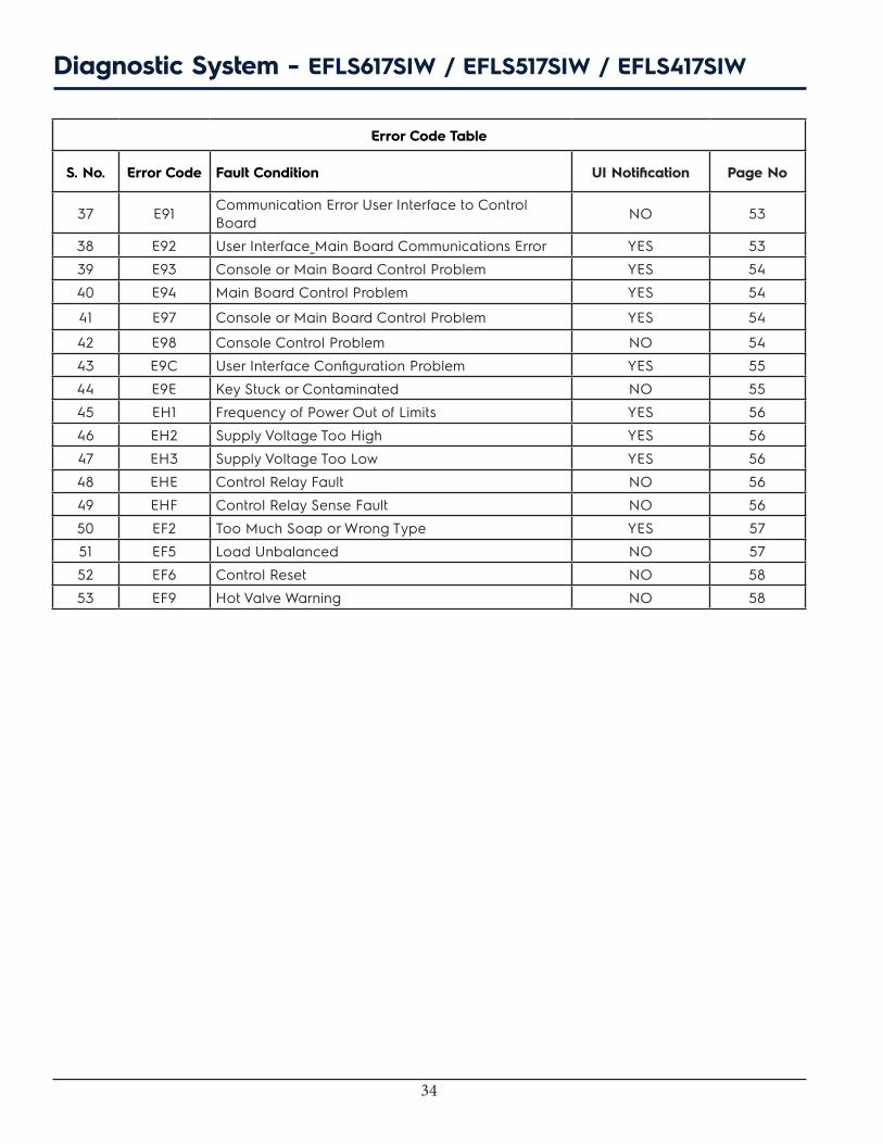
Error Code Table
S. No. Error Code Fault Condition UI Notification Page No
37 E91 Communication Error User Interface to Control Board NO 53
38 E92 User Interface_Main Board Communications Error YES 53
39 E93 Console or Main Board Control Problem YES 54
40 E94 Main Board Control Problem YES 54
41 E97 Console or Main Board Control Problem YES 54
42 E98 Console Control Problem NO 54
43 E9C User Interface Configuration Problem YES 55
44 E9E Key Stuck or Contaminated NO 55
45 EH1 Frequency of Power Out of Limits YES 56
46 EH2 Supply Voltage Too High YES 56
47 EH3 Supply Voltage Too Low YES 56
48 EHE Control Relay Fault NO 56
49 EHF Control Relay Sense Fault NO 56
50 EF2 Too Much Soap or Wrong Type YES 57
51 EF5 Load Unbalanced NO 57
52 EF6 Control Reset NO 58
53 EF9 Hot Valve Warning NO 58
Diagnostic System - EFLS617SIW / EFLS517SIW / EFLS417SIW
35
14. Troubleshooting Based on Error Codes
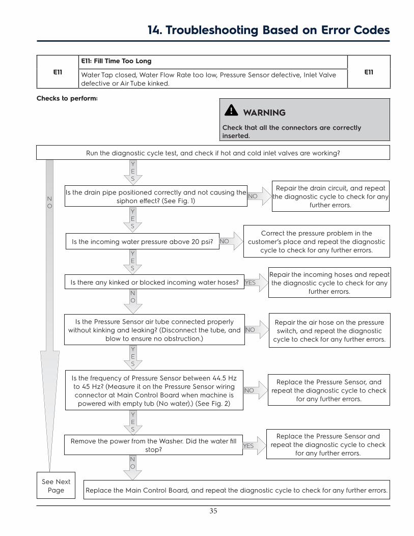
E11
E11: Fill Time Too Long
E11Water Tap closed, Water Flow Rate too low, Pressure Sensor defective, Inlet Valve defective or Air Tube kinked.
Checks to perform:
WARNING
Check that all the connectors are correctly inserted.
Is the incoming water pressure above 20 psi? Correct the pressure problem in the
customer’s place and repeat the diagnostic cycle to check for any further errors.
Is the Pressure Sensor air tube connected properly without kinking and leaking? (Disconnect the tube, and
blow to ensure no obstruction.)
Repair the air hose on the pressure switch, and repeat the diagnostic
cycle to check for any further errors.
NO
Is the drain pipe positioned correctly and not causing the siphon effect? (See Fig. 1)
Repair the drain circuit, and repeat the diagnostic cycle to check for any
further errors.
Replace the Main Control Board, and repeat the diagnostic cycle to check for any further errors.
NO
Run the diagnostic cycle test, and check if hot and cold inlet valves are working?
See Next Page
YES
YES
NO
YES
YES
Is there any kinked or blocked incoming water hoses?Repair the incoming hoses and repeat the diagnostic cycle to check for any
further errors.
Is the frequency of Pressure Sensor between 44.5 Hz to 45 Hz? (Measure it on the Pressure Sensor wiring connector at Main Control Board when machine is powered with empty tub (No water).) (See Fig. 2)
Replace the Pressure Sensor, and repeat the diagnostic cycle to check
for any further errors.NO
YES
Remove the power from the Washer. Did the water fill stop?
Replace the Pressure Sensor and repeat the diagnostic cycle to check
for any further errors.
YES
NO
YES
NO
NO
36
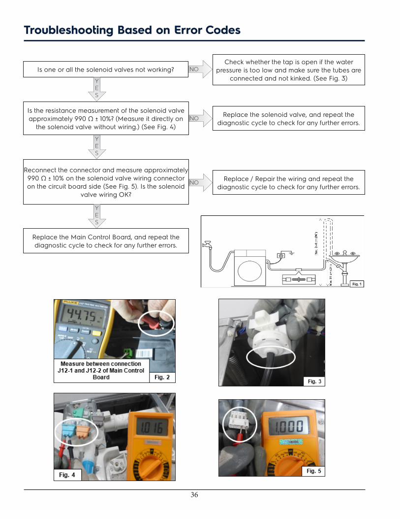
NOIs one or all the solenoid valves not working?
YES
Is the resistance measurement of the solenoid valve approximately 990 Ω ± 10%? (Measure it directly on
the solenoid valve without wiring.) (See Fig. 4)
YES
Reconnect the connector and measure approximately 990 Ω ± 10% on the solenoid valve wiring connector on the circuit board side (See Fig. 5). Is the solenoid
valve wiring OK?
Check whether the tap is open if the water pressure is too low and make sure the tubes are
connected and not kinked. (See Fig. 3)
Replace the solenoid valve, and repeat the diagnostic cycle to check for any further errors.
NO
YES
Replace the Main Control Board, and repeat the diagnostic cycle to check for any further errors.
Replace / Repair the wiring and repeat the diagnostic cycle to check for any further errors.
NO
Troubleshooting Based on Error Codes
37
E13
E13: Water Leak in Tub or in Pressure Sensor
E13Maximum overall water fill time exceeded (sum of all water fills between one drain phase and the next to avoid exceeding the maximum volume).
Checks to perform:
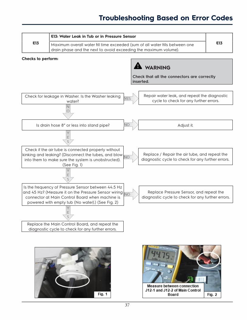
Check if the air tube is connected properly without kinking and leaking? (Disconnect the tubes, and blow into them to make sure the system is unobstructed).
(See Fig. 1)
Replace / Repair the air tube, and repeat the diagnostic cycle to check for any further errors.
Is the frequency of Pressure Sensor between 44.5 Hz and 45 Hz? (Measure it on the Pressure Sensor wiring
connector at Main Control Board when machine is powered with empty tub (No water).) (See Fig. 2)
Replace Pressure Sensor, and repeat the diagnostic cycle to check for any further errors.
Replace the Main Control Board, and repeat the diagnostic cycle to check for any further errors.
YES
YESCheck for leakage in Washer. Is the Washer leaking water?
Repair water leak, and repeat the diagnostic cycle to check for any further errors.
NO
WARNING
Check that all the connectors are correctly inserted.
NO
Troubleshooting Based on Error Codes
YES
NO
Is drain hose 8” or less into stand pipe?
YES
NO Adjust it.
38
E21
E21: Water Not Pumping Out Fast Enough
E21Drain Pipe blocked, Drain Pump defective, Pressure Sensor defective, or Main Board defective.
Checks to perform:
WARNING
Check that all the connectors are correctly inserted.
Is the drain filter clean (If filter available)?
YES
Is the drain system OK? (Drain pipe and water system of the home). (See Fig. 1)
YES
Clean the filter and repeat the diagnostic cycle to check for any further errors.
Disconnect and check the drain system, and repeat the diagnostic cycle to check for any
further errors.
NO
NO
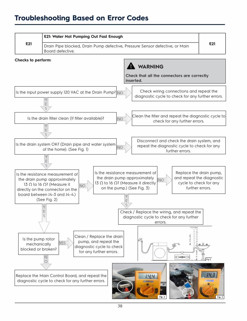
Is the resistance measurement of the drain pump approximately
13 Ω to 16 Ω? (Measure it directly on the connector on the board between J4-3 and J4-4.)
(See Fig. 2)
Is the resistance measurement of the drain pump approximately
13 Ω to 16 Ω? (Measure it directly on the pump.) (See Fig. 3)NO
NO
Replace the drain pump, and repeat the diagnostic
cycle to check for any further errors.
YES
Check / Replace the wiring, and repeat the diagnostic cycle to check for any further
errors.
Clean / Replace the drain pump, and repeat the
diagnostic cycle to check for any further errors.
Replace the Main Control Board, and repeat the diagnostic cycle to check for any further errors.
Is the pump rotor mechanically
blocked or broken?
NO
YES
YES
Is the input power supply 120 VAC at the Drain Pump?
YES
Check wiring connections and repeat the diagnostic cycle to check for any further errors.
NO
Troubleshooting Based on Error Codes

39
E23E23: Drain TRIAC Error
E23Drain Pump defective or Main Circuit Board defective.
E24E24: Drain TRIAC Error Sensing
E24Drain Pump defective, and Main Circuit Board defective.
Checks to perform:
WARNING
Check that all the connectors are correctly inserted.
Is the resistance measurement of the Drain Pump approximately 13 Ω to 17 Ω? (Measure it on the board
side between terminal J4-3 and J4-4.) (See Fig. 1)
Check / Replace the wiring, and repeat the diagnostic cycle to check for any further errors.
Is the resistance measurement of the Drain Pump approximately
13 Ω to 17 Ω? (Measure it directly on the pump.) (See Fig. 2)
Replace the Main Circuit Board and repeat the diagnostic cycle to check for any further errors.
NO
NOCheck / Replace the wiring, and repeat the diagnostic cycle to check for any further errors.
YES
NO
Replace the pump, and repeat the diagnostic cycle to check for any
further errors.YES
Measure it between pump connectors from main board and the Appliance body. Is resistance
value not “0”?
YES
Is the drain system OK? (Drain pipe and water system of the home.)
YES
Disconnect and check the drain system and repeat the diagnostic cycle to check for any
further errors.NO
Is the input power supply 120 VAC at the Drain Pump?
YES
Check wiring connections and repeat the diagnostic cycle to check for any further errors.
NO
Troubleshooting Based on Error Codes

40
E31E31: Electronic Pressure Switch Error
E31Pressure Sensor defective or Main Circuit Board defective.
E32
E32: Pressure Sensor Calibration Problem
E32Pressure Sensor defective or Main Control Board defective.
Checks to perform:
WARNING
Check that all the connectors are correctly inserted.
Check if air tube is connected properly without kinking and leaking? (Disconnect the tubes, and blow into them to make sure the system is unobstructed.)
(See Fig. 1)YES
Is the frequency of Pressure Sensor between 44.5 Hz and 45 Hz? (Measure it on the Pressure Sensor wiring
connector at Main Control Board when machine is powered with empty tub (No water).) (See Fig. 2)
YES
Replace / Repair the air tube, and repeat the diagnostic cycle to check for any further errors.
Replace Pressure Sensor and repeat the diagnostic cycle to check for any further error.
NO
NO
Replace the Main Control Board and repeat the diagnostic cycle to check for any further errors.
Troubleshooting Based on Error Codes
41
E35E35: Pressure Sensor Indicates Water Overfill
E35Water Inlet Valve defective, Air Tube kinked, Main Control Board defective.
E38E38: Air Trap Clogged
E38Water Inlet Valve defective, Air Tube kinked, Main Control Board defective.
Checks to perform:
WARNING
Check that all the connectors are correctly inserted.
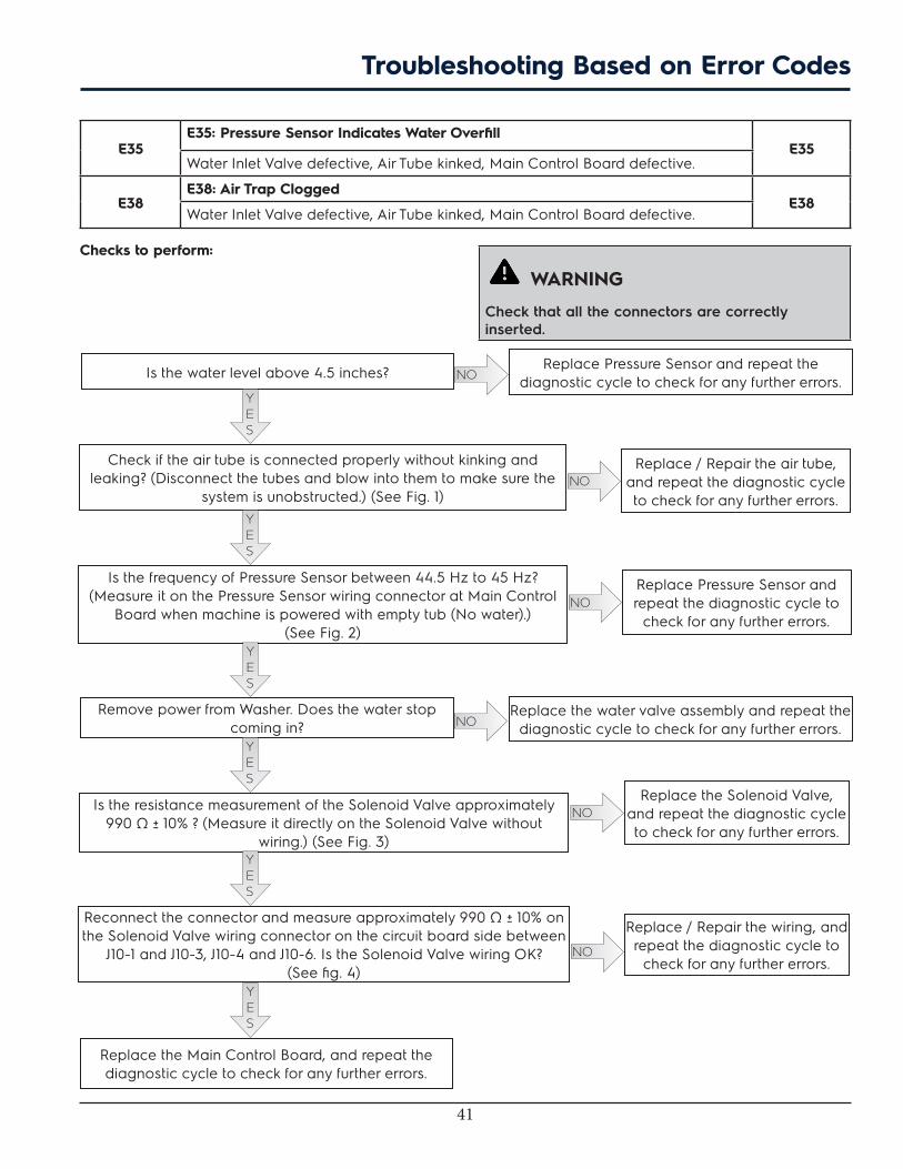
Check if the air tube is connected properly without kinking and leaking? (Disconnect the tubes and blow into them to make sure the
system is unobstructed.) (See Fig. 1)YES
Is the frequency of Pressure Sensor between 44.5 Hz to 45 Hz? (Measure it on the Pressure Sensor wiring connector at Main Control
Board when machine is powered with empty tub (No water).) (See Fig. 2)
Replace / Repair the air tube, and repeat the diagnostic cycle to check for any further errors.
Replace Pressure Sensor and repeat the diagnostic cycle to
check for any further errors.
NO
NO
Is the resistance measurement of the Solenoid Valve approximately 990 Ω ± 10% ? (Measure it directly on the Solenoid Valve without
wiring.) (See Fig. 3)YES
Reconnect the connector and measure approximately 990 Ω ± 10% on the Solenoid Valve wiring connector on the circuit board side between
J10-1 and J10-3, J10-4 and J10-6. Is the Solenoid Valve wiring OK? (See fig. 4)
Replace the Solenoid Valve, and repeat the diagnostic cycle to check for any further errors.
Replace / Repair the wiring, and repeat the diagnostic cycle to
check for any further errors.
NO
NO
YES
YES
Replace the Main Control Board, and repeat the diagnostic cycle to check for any further errors.
Is the water level above 4.5 inches?
YES
Replace Pressure Sensor and repeat the diagnostic cycle to check for any further errors.NO
Remove power from Washer. Does the water stop coming in?
YES
Replace the water valve assembly and repeat the diagnostic cycle to check for any further errors.NO
Troubleshooting Based on Error Codes

42
E41E41: Control Board Thinks Door Switch Is Open
E41Lid Lock Device defective, Main Control Board defective.
E42E42: Door Lock Device Failure
E42Lid Lock Device defective, Main Control Board defective.
E43E43: Door Lock TRIAC Failure
E43Lid Lock Device defective, Main Control Board defective.
E44E44: Door Closed Sensing Failure
E44Lid Lock Device defective, Main Control Board defective.
E45E45: Line Door Sensing Failure
E45Lid Lock Device defective, Main Control Board defective.
Checks to perform:
WARNING
Check that all the connectors are correctly inserted.
Replace the Lid Switch, and repeat the diagnostic cycle to check for any further errors.NO
Replace the Main Control Board, and repeat the diagnostic cycle to check for any further errors.
YES
Replace the Lid Lock device (with wire), and repeat the diagnostic cycle to check for any further errors.
Still getting same error?
Clear the obstacle, and repeat the diagnostic cycle to check for any further errors.
Check the continuity for the Lid Switch. Is the Lid Switch OK?YES
Check if any obstacles stick to the Lid Lock which prevents from locking the door?
NO
YES
Troubleshooting Based on Error Codes
43
E57
E57: High Current on Inverter
E57Motor Protector Open, Washer Load too heavy, Wiring problem, Motor defective, or Motor Control Board defective.
E58
E58: High Current on Motor Phase
E58Motor Protector Open, Laundry Load too heavy, Wiring problem, Motor defective, Motor Control Board defective.
Checks to perform:
WARNING
Check that all the connectors are correctly inserted.
Check if the power supply is as per product specifications?
Make the laundry as per product specifications, and repeat the diagnostic cycle to check for any further errors.
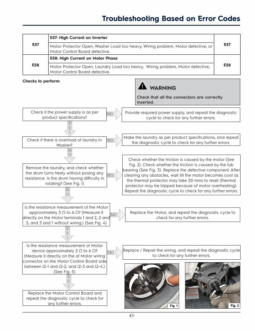
Check whether the friction is caused by the motor (See Fig. 2). Check whether the friction is caused by the tub
bearing (See Fig. 3). Replace the defective component. After clearing any obstacles, wait till the motor becomes cool as
the thermal protector may take 30 mins to reset (thermal protector may be tripped because of motor overheating). Repeat the diagnostic cycle to check for any further errors.
Remove the laundry, and check whether the drum turns freely without posing any resistance. Is the drum having difficulty in
rotating? (See Fig. 1)
YES
NO Provide required power supply, and repeat the diagnostic cycle to check for any further errors.
Check if there is overload of laundry in Washer?
YES
NO
YES
Is the resistance measurement of the Motor approximately 3 Ω to 6 Ω? (Measure it
directly on the Motor terminals 1 and 2, 2 and 3, and 3 and 1 without wiring.) (See Fig. 4)
YES
NO Replace the Motor, and repeat the diagnostic cycle to check for any further errors.
Is the resistance measurement of Motor device approximately 3 Ω to 6 Ω?
(Measure it directly on the of Motor wiring connector on the Motor Control Board side between J2-1 and J2-2, and J2-3 and J2-4.)
(See Fig. 5)YES
Replace the Motor Control Board and repeat the diagnostic cycle to check for
any further errors.
NO Replace / Repair the wiring, and repeat the diagnostic cycle to check for any further errors.
NO
Troubleshooting Based on Error Codes

44
E59E59: No Spin Signal for 3 Seconds
E59Wiring problem, Motor defective, Motor Control Board defective.
E55E55: Under Speed
E55Wiring problem, Motor defective, Motor Control Board defective.
Checks to perform:
WARNING
Check that all the connectors are correctly inserted.
Check if the power supply is as per product specifications?
YES
Remove the laundry, and check whether the drum turns freely
without posing any resistance. Is the drum having difficulty in
rotating? (See Fig. 1)
Provide required power supply, and repeat the diagnostic cycle to check for any further errors.
Check whether the friction is caused by the motor (See Fig. 2). Check whether the friction is caused by the tub bearing (See Fig. 3). Replace the defective component. After clearing any obstacles, wait
till the motor becomes cool as the thermal protector may take 30 mins to reset (thermal protector may be tripped because of motor overheating). Repeat the diagnostic cycle to check for any further
errors.
NO
NO
YES
NO
Is the resistance measurement of Motor device approximately 3 Ω to 6 Ω? (Measure it directly on the of Motor wiring connector on the
Motor Control Board side between J2-1 and J2-2, and J2-3 and J2-4.)
(See Fig. 4)
Is the resistance measurement of the Motor approximately 3 Ω to 6
Ω? (Measure it directly on the Motor terminals 1 and 2, 2 and 3, and 3 and 1 without wiring). (See Fig. 5)
Replace the Motor, and repeat the diagnostic cycle to check for any
further errors.
NO
YES
YES
Check / Replace the wiring, and repeat the diagnostic cycle to check for any further errors.
Replace the Motor Control Board, and repeat the diagnostic cycle to check for any further errors.
Troubleshooting Based on Error Codes

45
Troubleshooting Based on Error Codes
46
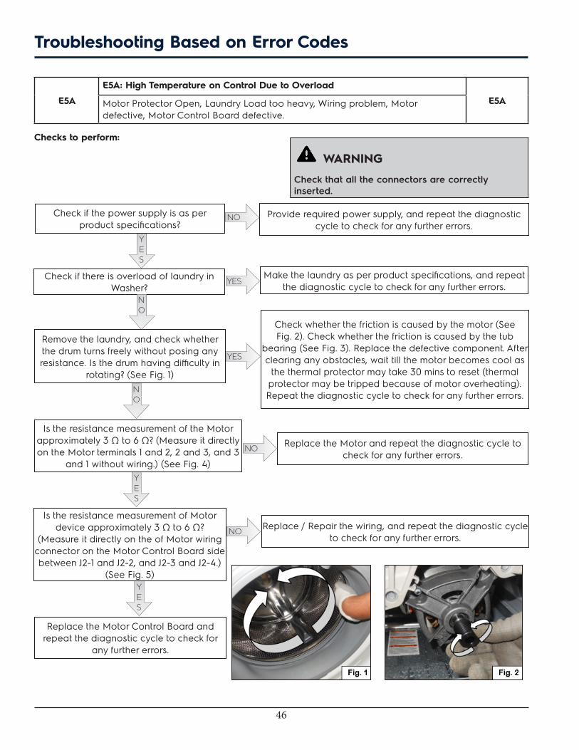
E5A
E5A: High Temperature on Control Due to Overload
E5AMotor Protector Open, Laundry Load too heavy, Wiring problem, Motor defective, Motor Control Board defective.
Checks to perform:
WARNING
Check that all the connectors are correctly inserted.
Check if the power supply is as per product specifications?
Make the laundry as per product specifications, and repeat the diagnostic cycle to check for any further errors.
Check whether the friction is caused by the motor (See Fig. 2). Check whether the friction is caused by the tub
bearing (See Fig. 3). Replace the defective component. After clearing any obstacles, wait till the motor becomes cool as
the thermal protector may take 30 mins to reset (thermal protector may be tripped because of motor overheating). Repeat the diagnostic cycle to check for any further errors.
Remove the laundry, and check whether the drum turns freely without posing any resistance. Is the drum having difficulty in
rotating? (See Fig. 1)
YES
NO Provide required power supply, and repeat the diagnostic cycle to check for any further errors.
Check if there is overload of laundry in Washer?
YES
NO
YES
Is the resistance measurement of the Motor approximately 3 Ω to 6 Ω? (Measure it directly on the Motor terminals 1 and 2, 2 and 3, and 3
and 1 without wiring.) (See Fig. 4)YES
NO Replace the Motor and repeat the diagnostic cycle to check for any further errors.
Is the resistance measurement of Motor device approximately 3 Ω to 6 Ω?
(Measure it directly on the of Motor wiring connector on the Motor Control Board side between J2-1 and J2-2, and J2-3 and J2-4.)
(See Fig. 5)YES
Replace the Motor Control Board and repeat the diagnostic cycle to check for
any further errors.
NO Replace / Repair the wiring, and repeat the diagnostic cycle to check for any further errors.
NO
Troubleshooting Based on Error Codes
47
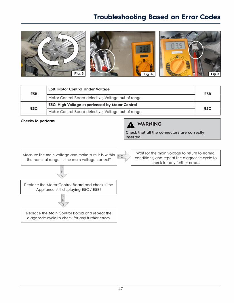
E5BE5B: Motor Control Under Voltage
E5BMotor Control Board defective, Voltage out of range.
E5CE5C: High Voltage experienced by Motor Control
E5CMotor Control Board defective, Voltage out of range.
Checks to perform: WARNING
Check that all the connectors are correctly inserted.
Measure the main voltage and make sure it is within the nominal range. Is the main voltage correct?
YES
NOWait for the main voltage to return to normal
conditions, and repeat the diagnostic cycle to check for any further errors.
Replace the Motor Control Board and check if the Appliance still displaying E5C / E5B?
YES
Replace the Main Control Board and repeat the diagnostic cycle to check for any further errors.
Troubleshooting Based on Error Codes

48
E5DE5D: Communication Problem with Motor Control
E5DMain Circuit Board defective, Motor Control Board defective, Wiring problem.
E5EE5E: Communication Problem from Motor Control
E5EMain Circuit Board defective, Motor Control Board defective, Wiring problem.
E5FE5F: Motor Control is Continuously Resetting
E5FMain Circuit Board defective, Motor Control Board defective, Wiring problem.
Checks to perform: WARNING
Check that all the connectors are correctly inserted.
YES
Are connectors of Main Control Board and Motor Control Board properly inserted?
Repair the connectors, and repeat the diagnostic cycle to check for any further errors.
NO
Measure the continuity between J14 connectors (Main Circuit Board) and J1 connectors (Motor Control
Board). Is the wiring OK?
YES
Replace the Motor Control Board, and repeat the diagnostic cycle to check for any further errors. Is the
Appliance working?
Replace the wiring, and repeat the diagnostic cycle to check for any further errors.
Replace the Main Control Board, and repeat the diagnostic cycle to check for any further errors.
NO
NO
Troubleshooting Based on Error Codes
49
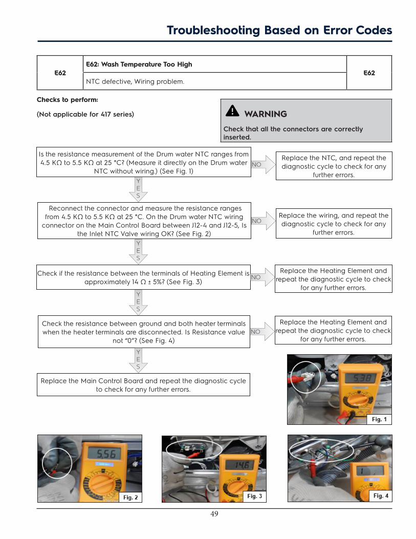
E62E62: Wash Temperature Too High
E62NTC defective, Wiring problem.
Checks to perform:
(Not applicable for 417 series) WARNING
Check that all the connectors are correctly inserted.
YES
Is the resistance measurement of the Drum water NTC ranges from 4.5 KΩ to 5.5 KΩ at 25 °C? (Measure it directly on the Drum water
NTC without wiring.) (See Fig. 1)
Replace the NTC, and repeat the diagnostic cycle to check for any
further errors.NO
Reconnect the connector and measure the resistance ranges from 4.5 KΩ to 5.5 KΩ at 25 °C. On the Drum water NTC wiring
connector on the Main Control Board between J12-4 and J12-5, Is the Inlet NTC Valve wiring OK? (See Fig. 2)
YES
Replace the Main Control Board and repeat the diagnostic cycle to check for any further errors.
Replace the wiring, and repeat the diagnostic cycle to check for any
further errors.
NO
YES
Check if the resistance between the terminals of Heating Element is approximately 14 Ω ± 5%? (See Fig. 3)
Replace the Heating Element and repeat the diagnostic cycle to check
for any further errors.NO
Check the resistance between ground and both heater terminals when the heater terminals are disconnected. Is Resistance value
not “0”? (See Fig. 4)
Replace the Heating Element and repeat the diagnostic cycle to check
for any further errors.NO
YES
Troubleshooting Based on Error Codes
50
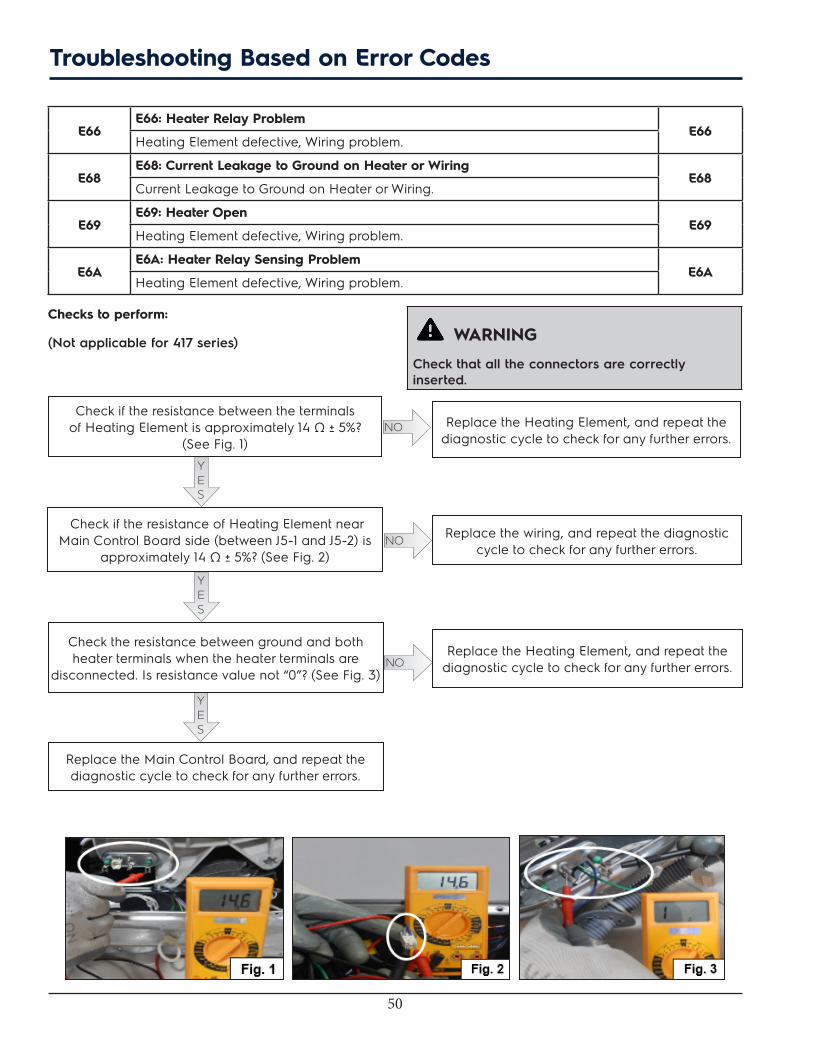
E66E66: Heater Relay Problem
E66Heating Element defective, Wiring problem.
E68E68: Current Leakage to Ground on Heater or Wiring
E68Current Leakage to Ground on Heater or Wiring.
E69E69: Heater Open
E69Heating Element defective, Wiring problem.
E6AE6A: Heater Relay Sensing Problem
E6AHeating Element defective, Wiring problem.
Checks to perform:
(Not applicable for 417 series) WARNING
Check that all the connectors are correctly inserted.
Check if the resistance between the terminals of Heating Element is approximately 14 Ω ± 5%?
(See Fig. 1)
YES
Check if the resistance of Heating Element near Main Control Board side (between J5-1 and J5-2) is
approximately 14 Ω ± 5%? (See Fig. 2)
YES
Check the resistance between ground and both heater terminals when the heater terminals are
disconnected. Is resistance value not “0”? (See Fig. 3)
Replace the Heating Element, and repeat the diagnostic cycle to check for any further errors.
Replace the wiring, and repeat the diagnostic cycle to check for any further errors.
NO
NO
Replace the Heating Element, and repeat the diagnostic cycle to check for any further errors.NO
YES
Replace the Main Control Board, and repeat the diagnostic cycle to check for any further errors.
Troubleshooting Based on Error Codes
51
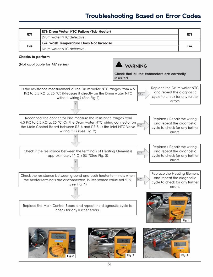
E71E71: Drum Water NTC Failure (Tub Heater)
E71Drum water NTC defective.
E74E74: Wash Temperature Does Not Increase
E74Drum water NTC defective.
Checks to perform:
(Not applicable for 417 series) WARNING
Check that all the connectors are correctly inserted.
YES
Is the resistance measurement of the Drum water NTC ranges from 4.5 KΩ to 5.5 KΩ at 25 °C? (Measure it directly on the Drum water NTC
without wiring.) (See Fig. 1)
Replace the Drum water NTC, and repeat the diagnostic
cycle to check for any further errors.
NO
Reconnect the connector and measure the resistance ranges from 4.5 KΩ to 5.5 KΩ at 25 °C. On the Drum water NTC wiring connector on the Main Control Board between J12-4 and J12-5, Is the Inlet NTC Valve
wiring OK? (See Fig. 2)YES
Check if the resistance between the terminals of Heating Element is approximately 14 Ω ± 5% ?(See Fig. 3)
Replace / Repair the wiring, and repeat the diagnostic
cycle to check for any further errors.
NO
Replace / Repair the wiring, and repeat the diagnostic
cycle to check for any further errors.
NO
Check the resistance between ground and both heater terminals when the heater terminals are disconnected. Is Resistance value not “0”?
(See Fig. 4)YES
Replace the Main Control Board and repeat the diagnostic cycle to check for any further errors.
Replace the Heating Element and repeat the diagnostic
cycle to check for any further errors.
NO
YES
Troubleshooting Based on Error Codes
52
Troubleshooting Based on Error Codes
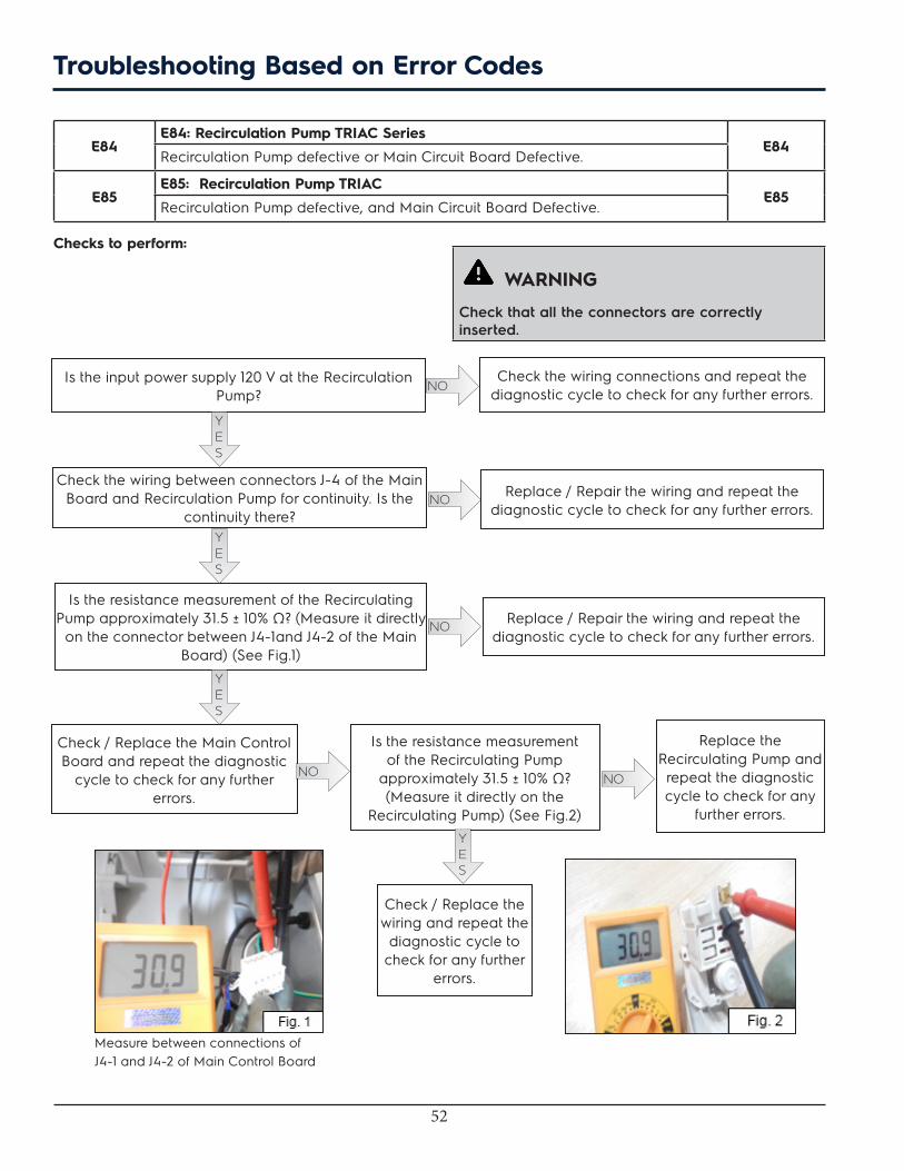
E84E84: Recirculation Pump TRIAC Series
E84Recirculation Pump defective or Main Circuit Board Defective.
E85E85: Recirculation Pump TRIAC
E85Recirculation Pump defective, and Main Circuit Board Defective.
Checks to perform:
WARNING
Check that all the connectors are correctly inserted.
Is the input power supply 120 V at the Recirculation Pump?
YES
Check the wiring between connectors J-4 of the Main Board and Recirculation Pump for continuity. Is the
continuity there?
Check the wiring connections and repeat the diagnostic cycle to check for any further errors.
Replace / Repair the wiring and repeat the diagnostic cycle to check for any further errors.
NO
NO
Check / Replace the Main Control Board and repeat the diagnostic
cycle to check for any further errors.
Is the resistance measurement of the Recirculating Pump
approximately 31.5 ± 10% Ω? (Measure it directly on the
Recirculating Pump) (See Fig.2)
Replace the Recirculating Pump and repeat the diagnostic cycle to check for any
further errors.
NO
YES
Check / Replace the wiring and repeat the diagnostic cycle to
check for any further errors.
YES
Is the resistance measurement of the Recirculating Pump approximately 31.5 ± 10% Ω? (Measure it directly
on the connector between J4-1and J4-2 of the Main Board) (See Fig.1)
NO
NO Replace / Repair the wiring and repeat the diagnostic cycle to check for any further errors.
YES
Measure between connections of J4-1 and J4-2 of Main Control Board

53
E83E83: Wrong Selector Reading
E83Wrong configuration data loaded or Electronic Control Board defective.
E86E86: Incorrect User Interface Selection Table
E86Wrong configuration data loaded or Electronic Control Board defective.
E87E87: User Interface Micro-Controller Fault
E87Wrong configuration data loaded or Electronic Control Board defective.
Checks to perform:
E91E91: Communication Error User Interface to Control Board
E91User Interface Board defective, Main Control Board defective, Wiring defective.
E92E92: User Interface_Main Board Communications Error
E92User Interface Board defective, Main Control Board defective, Wiring defective.
Checks to perform:
WARNING
Check that all the connectors are correctly inserted.
WARNING
Check that all the connectors are correctly inserted.
Disconnect the connector J16 which connects Electronic control Board and User Interface Board. Does the E91 / E92 error appear
again?YES
Check the wiring between the Main control Board and the User Interface Board. Is the wiring OK?
YES
Replace the User Interface Board and repeat the diagnostic cycle to check for any further errors. Is the Appliance still
displaying E91 / E92?
Replace the Main Control Board, and repeat the diagnostic cycle to check
for any further errors.
Replace / Repair the wiring, and repeat the diagnostic cycle to check
for any further errors.
NO
NO
Appliance is OK.NO
YES
Replace the Main Control Board and repeat the diagnostic cycle to check for any further errors.
Check if correct Cycle Selector Board, User Interface Board, Motor Control Board and Electronic control Board are installed and also wiring between them. If not then replace the respective board or wiring and repeat the
diagnostic cycle to check for any further errors. Incorrect configuration possible.
Troubleshooting Based on Error Codes

54
E93E93: Console or Main Board Control Problem
E93Software problem between Main Board and Control Board.
E94E94: Main Board Control Problem
E94Software problem between Main Board and Control Board.
E97E97: Console or Main Board Control Problem
E97Software problem between Main Board and Control Board.
Checks to perform:
E98E98: Console Control Problem
E98Main Circuit Board defective, Motor Control Board defective, Wiring problem.
Checks to perform:
WARNING
Check that all the connectors are correctly inserted.
WARNING
Check that all the connectors are correctly inserted.
Check if correct User Interface Board, Motor Control Board and Electronic Control Board are installed, and check the wiring between them. If not then replace the respective board or wiring and repeat the diagnostic
cycle to check for any further errors.
Are connectors of Main Control Board and Motor Control Board properly inserted?
YES
Measure the continuity between J14 connectors (Main Control Board) and J1 connectors (Motor Control
Board). Is the wiring OK?
YES
Replace the Motor Control Board, and repeat the diagnostic cycle to check for any further errors. Is the
Appliance working?
Repair the connectors, and repeat the diagnostic cycle to check for any further errors.
Replace the wiring, and repeat the diagnostic cycle to check for any further errors.
NO
NO
Replace the Main Control Board, and repeat the diagnostic cycle to check for any further errors.NO
Troubleshooting Based on Error Codes
55
E9CE9C: User Interface Configuration Problem
E9CMain Circuit Board defective, Motor Control Board defective, Wiring problem.
Checks to perform:
E9EE9E: Key Stuck or Contaminated
E9EUser Interface Board defective , Control Panel defective.
Checks to perform:
WARNING
Check that all the connectors are correctly inserted.
WARNING
Check that all the connectors are correctly inserted.
Disconnect the connector J16 which connects Electronic control Board and J5 of User Interface Board. Does the E9C error appear
again?
YES
Check the wiring between the Main Control Board and the User Interface Board.
• Detach and reconnect the connectors on both boards several times.
• Measure the continuity between connector J16 (Main Control Board) and J5 (User Interface Board).
Is the wiring OK?YES
Replace the User Interface Board, and repeat the diagnostic cycle to check for any further errors. Is the Appliance still displaying E9C?
Replace the Main Control Board, and repeat the diagnostic cycle to
check for any further errors.
Replace / Repair the wiring, and repeat the diagnostic cycle to
check for any further errors.
NO
NO
Appliance is OK.NO
YES
Replace the Main Control Board, and repeat the diagnostic cycle to check for any further errors.
Clean buttons and spring alignment in User Interface assembly. Is the Appliance still displaying E9E? If yes, then replace User Interface Board and repeat the diagnostic cycle to check for any further errors.
Troubleshooting Based on Error Codes
56
EH1EH1: Frequency of Power Out of Limits
EH1Main Circuit Board defective, Fluctuation in input.
EH2EH2: Supply Voltage Too High
EH2Main Circuit Board defective, Fluctuation in input.
EH3EH3: Supply Voltage Too Low
EH3Main Circuit Board defective, Fluctuation in input.
EHEEHE: Control Relay Fault
EHEMain Circuit Board defective, Fluctuation in input.
EHFEHF: Control Relay Sense Fault
EHFMain Circuit Board defective, Fluctuation in input.
Checks to perform:
WARNING
Check that all the connectors are correctly inserted.
Measure the main voltage / frequency and make sure it is within the nominal range. Is the mains voltage
correct?
YES
Check power wiring to motor board. Are wiring connections OK?
YES
Replace the Motor Control Board and check if the Appliance still displaying EB1 / EB2 / EB3 / EBE / EBF?
Provide voltage / frequency as per product specification and repeat the diagnostic cycle to
check for any further errors.NO
YES
Check power wiring to main board. Are wiring connections OK?
YES
Replace the Main Control Board, and repeat the diagnostic cycle to check for any further errors.
Repair the wiring and repeat the diagnostic cycle to check for any further errors.
NO
Repair the wiring and repeat the diagnostic cycle to check for any further errors.
NO
Troubleshooting Based on Error Codes
Appliance is OK.NO
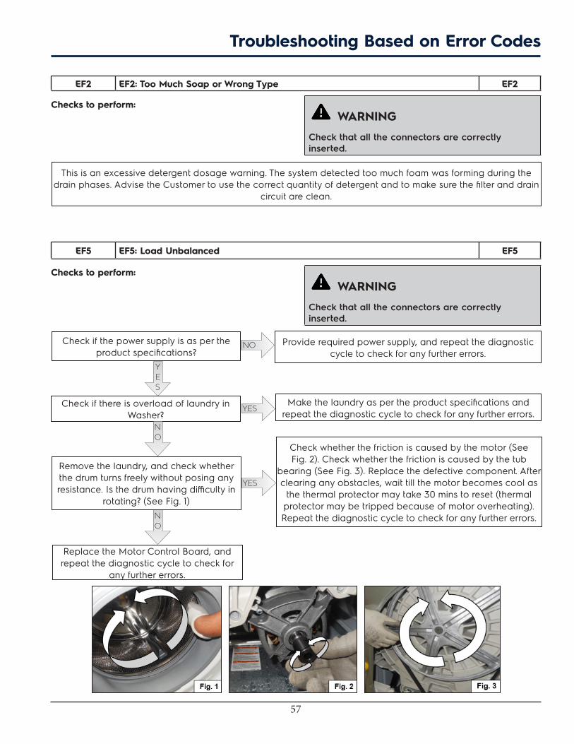
57
This is an excessive detergent dosage warning. The system detected too much foam was forming during the drain phases. Advise the Customer to use the correct quantity of detergent and to make sure the filter and drain
circuit are clean.
EF2 EF2: Too Much Soap or Wrong Type EF2
Checks to perform:
EF5 EF5: Load Unbalanced EF5
Checks to perform:
WARNING
Check that all the connectors are correctly inserted.
WARNING
Check that all the connectors are correctly inserted.
Check if the power supply is as per the product specifications?
Make the laundry as per the product specifications and repeat the diagnostic cycle to check for any further errors.
Check whether the friction is caused by the motor (See Fig. 2). Check whether the friction is caused by the tub
bearing (See Fig. 3). Replace the defective component. After clearing any obstacles, wait till the motor becomes cool as
the thermal protector may take 30 mins to reset (thermal protector may be tripped because of motor overheating). Repeat the diagnostic cycle to check for any further errors.
Remove the laundry, and check whether the drum turns freely without posing any resistance. Is the drum having difficulty in
rotating? (See Fig. 1)
YES
NO Provide required power supply, and repeat the diagnostic cycle to check for any further errors.
Check if there is overload of laundry in Washer?
YES
NO
YES
Replace the Motor Control Board, and repeat the diagnostic cycle to check for
any further errors.
NO
Troubleshooting Based on Error Codes
58
EF6 EF6: Control Reset EF6
Checks to perform:
EF9EF9: Hot Valve Warning
EF9Hot and Cold Hose reversed.
Checks to perform:
WARNING
Check that all the connectors are correctly inserted.
WARNING
Check that all the connectors are correctly inserted.
Check wiring to main board. Unplug the unit for 1 minute and retry. If problem is not corrected replace Main Control Board.
Troubleshooting Based on Error Codes
Check for the water supply line. Is the continuity flow of water is there?
YES
Check if the Hot and Cold water hoses are connecting to their respective Hot and Cold Valve?
YES
Is the temperature of Hot water same as the Cold water?
Check for the water supply line, power connection and repeat the diagnostic cycle to
check for any further errors.NO
YES
Fix the Hot water in the house supply.
Switch back the Cold and Hot water hoses to their correct position and repeat the diagnostic
cycle to check for any further errors.NO
Check for Main Control Board and repeat the diagnostic cycle to check for any further errors.
NO