Front-End Processing for Monopulse Doppler Radar · Front-End Processing for Monopulse Doppler...
38
Disclaimer: This document was part of the DSP Solution Challenge 1995 European Team Papers. It may have been written by someone whose native language is not English. TI assumes no liability for the quality of writing and/or the accuracy of the information contained herein. Front-End Processing for Monopulse Doppler Radar Authors: P.H. Dezaux, X. Gilles, S. Marques EFRIE, France December 1995 SPRA299
Transcript of Front-End Processing for Monopulse Doppler Radar · Front-End Processing for Monopulse Doppler...

Disclaimer: This document was part of the DSPSolution Challenge 1995 European Team Papers. Itmay have been written by someone whose nativelanguage is not English. TI assumes no liability for thequality of writing and/or the accuracy of theinformation contained herein.
Front-End Processing for MonopulseDoppler Radar
Authors: P.H. Dezaux, X. Gilles, S. Marques
EFRIE, FranceDecember 1995SPRA299
IMPORTANT NOTICE
Texas Instruments (TI) reserves the right to make changes to its products or to discontinue anysemiconductor product or service without notice, and advises its customers to obtain the latest version ofrelevant information to verify, before placing orders, that the information being relied on is current.
TI warrants performance of its semiconductor products and related software to the specifications applicableat the time of sale in accordance with TI’s standard warranty. Testing and other quality control techniquesare utilized to the extent TI deems necessary to support this warranty. Specific testing of all parameters ofeach device is not necessarily performed, except those mandated by government requirements.
Certain application using semiconductor products may involve potential risks of death, personal injury, orsevere property or environmental damage (“Critical Applications”).
TI SEMICONDUCTOR PRODUCTS ARE NOT DESIGNED, INTENDED, AUTHORIZED, OR WARRANTEDTO BE SUITABLE FOR USE IN LIFE-SUPPORT APPLICATIONS, DEVICES OR SYSTEMS OR OTHERCRITICAL APPLICATIONS.
Inclusion of TI products in such applications is understood to be fully at the risk of the customer. Use of TIproducts in such applications requires the written approval of an appropriate TI officer. Questions concerningpotential risk applications should be directed to TI through a local SC sales office.
In order to minimize risks associated with the customer’s applications, adequate design and operatingsafeguards should be provided by the customer to minimize inherent or procedural hazards.
TI assumes no liability for applications assistance, customer product design, software performance, orinfringement of patents or services described herein. Nor does TI warrant or represent that any license,either express or implied, is granted under any patent right, copyright, mask work right, or other intellectualproperty right of TI covering or relating to any combination, machine, or process in which suchsemiconductor products or services might be or are used.
Copyright © 1997, Texas Instruments Incorporated

TRADEMARKS
TI is a trademark of Texas Instruments Incorporated.
Other brands and names are the property of their respective owners.

CONTACT INFORMATION
US TMS320 HOTLINE (281) 274-2320
US TMS320 FAX (281) 274-2324
US TMS320 BBS (281) 274-2323
US TMS320 email [email protected]

ContentsAbstract ....................................................................................................................... .......7Product Support on the World Wide Web ......................................................................8Introduction ........................................................................................................................9Overall Hardware/Software Description ...................................................................... 11
Video Amplification ..................................................................................................... 11Analog to Digital Conversion...................................................................................... 11Input Interface Between DSP and ADC..................................................................... 12Digital Pulse Compression ......................................................................................... 13
General Description ........................................................................................... 13Overview of the Calculation ............................................................................... 15Digital Correlation Formula ................................................................................ 15Hardware Description and Algorithm................................................................. 15
Doppler Processing .................................................................................................... 16Calculations........................................................................................................ 16C Program .......................................................................................................... 19Approximate Modulus ........................................................................................ 19
Output Interface with the Digital Tracker.................................................................... 20Communication with the Radar Manager................................................................... 20
Architecture ........................................................................................................ 20Configuration ...................................................................................................... 21Global Variables Needed for Digital Calculations.............................................. 22Transmission Protocol........................................................................................ 22
Performances and Conclusion ..................................................................................... 24Appendices ..................................................................................................................... 26Glossary....................................................................................................................... .... 38
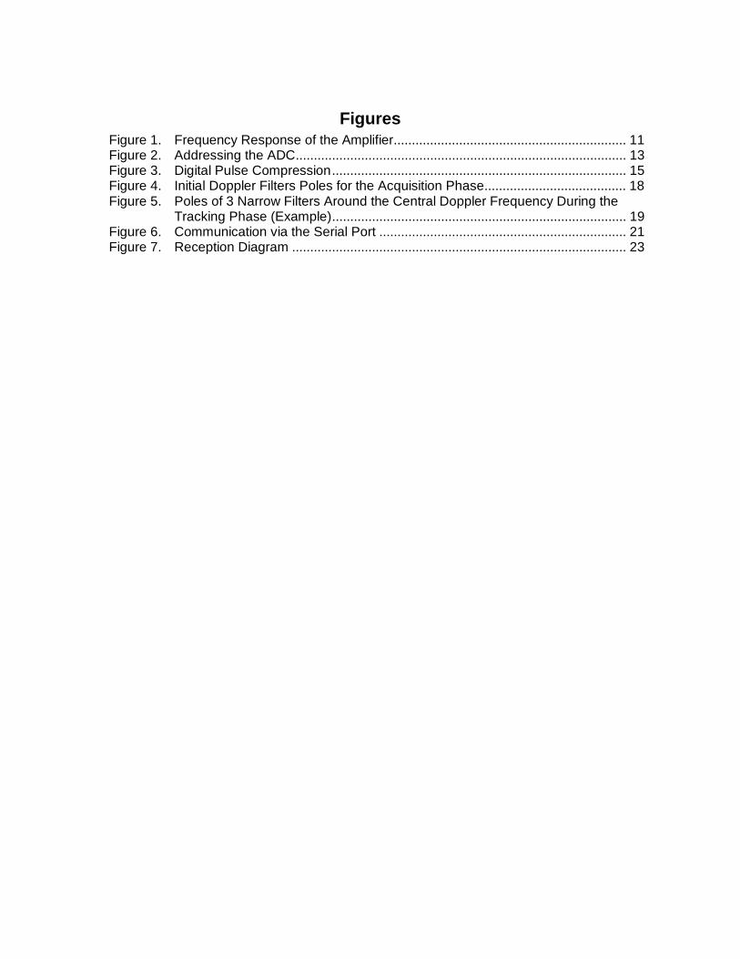
FiguresFigure 1. Frequency Response of the Amplifier................................................................ 11Figure 2. Addressing the ADC........................................................................................... 13Figure 3. Digital Pulse Compression................................................................................. 15Figure 4. Initial Doppler Filters Poles for the Acquisition Phase....................................... 18Figure 5. Poles of 3 Narrow Filters Around the Central Doppler Frequency During the
Tracking Phase (Example)................................................................................. 19Figure 6. Communication via the Serial Port .................................................................... 21Figure 7. Reception Diagram ............................................................................................ 23
Front-End Processing for Monopulse Doppler Radar 7
Front-End Processing for MonopulseDoppler Radar
Abstract
FEPMR is standing for Front-End and Doppler Processing forMonopulse Doppler Radar. It is a PCB at the frontier between theRF and the Digital Circuits for the radar AXIR. There are fourchannels, corresponding to the four squinted beams of theantenna ( Right, Left, Up and Down ). Each beam channel isprocessed in phase (I) and quadrature ( Q) real baseband signals.
The eight video analog signals are amplified and then convertedby 8 ADC ( Analog to Digital Converters ). Four Texas Instruments(TI) TMS320C50 dgital signal processors (DSPs) ( one for eachbeam channel ) are operating two major algorithms in cascade.
� A flexible FIR ( Finite Impulse Response ) Digital Filter withcomplex coefficients is first applied as a Digital PulseCompressor to provide 16 range bins. AXIR transmitter isusing a quadriphase sequence (1 up to 31 sub-pulses).Coefficients for the reference code are optimised by the RadarManager ( project C ) to reduce the range side lobes.
� The second part implements three IIR ( Infinite ImpulseResponse ) Digital Filters, using also complex coefficients as aDoppler filter. These coefficients are dynamically computed bythe Radar Manager ( project C ) as a function of the trackedtarget range and Doppler. An output time decimation isprovided in accordance with the coherent and non-coherentintegration process.

SPRA299
8 Front-End Processing for Monopulse Doppler Radar
For each beam, each range cell and each Doppler, the I and Qsignals are combined to form magnitudes to be delivered to theTRACKER ( project B ) via 4 dual-port RAM. At the end of thedigital calculations, there are 4 * 16 * 3 bins, correspondingrespectively to the 4 beams, the 16 ranges and the 3 Dopplerfilters. The output rate is fixed to 2 ms, independently of theflexible Pulse Repetition Interval ( PRI ) controlled dynamicallyby the Radar Manager.
This project is implemented on a Printed Circuit Board ( PCB ),using four TMS320C50. In a close future, a single TMS320C82could probably do the same job within the same real timespecifications because of its improvements.
This document was an entry in the 1995 DSP SolutionsChallenge, an annual contest organized by TI to encouragestudents from around the world to find innovative ways to useDSPs. For more information on the TI DSP Solutions Challenge,see TI’s World Wide Web site at www.ti.com.
Product Support on the World Wide Web
Our World Wide Web site at www.ti.com contains the most up todate product information, revisions, and additions. Usersregistering with TI&ME can build custom information pages andreceive new product updates automatically via email.
SPRA299
Front-End Processing for Monopulse Doppler Radar 9
Introduction
This project deals with the study of a Front-End Processing for aMonopulse Doppler Radar ( FEPMR ), in charge of PulseCompression and Doppler Digital Filtering. AXIR ( AutomaticXband Instrumentation Radar ) is a concept of a low cost radar,specially designed for the TEXAS INSTRUMENTS DSPSOLUTIONS CHALLENGE. The idea was to use theperformances of the TMS320C4x and TMS320C5x families todesign a performant and intelligent radar processing, made ofmultiprocessors DSP chips.
The objective product cost is under 80.000 $ for the completeradar, including the pedestal, the antenna, the transmitter, theR.F. Front-End processors and the display. AXIR is basically aMonopulse Doppler Ground Based Radar with many civilianapplications:� Tracking of Meteo sounders.� Cloud Doppler analysis for Meteo purposes.� Short range air control for parallel runways or difficult access
airports.� Wind shear and burst detection.� Trajectory control for sportive aerobatics events or air clubs.� General low cost instrumentation radar ( radar cross section
evaluation, tutorial radar for universities, private air-tracking…).
The radar processor has been divided into four separate projectssubmitted to the TI challenge, respectively in charge of thefollowing tasks:
A. FRONT END & DOPPLER PROCESSING (this project)
B. DIGITAL TRACKER.
C. RADAR MANAGER.
D. TARGET SIMULATOR.
AXIR features modern technology for the other sub-systems. Theantenna is a planar Monopulse array of printed patches. Thetransmitter, the stalo and the R.F. homodyne Front-End are 100 %solid-state. All the circuits and the processors are located at theback of the thin antenna.
SPRA299
10 Front-End Processing for Monopulse Doppler Radar
The pedestal uses robotics low cost and modern technology. Theantenna box is free to rotate 360°, both in azimuth and elevation. Astandard PC, under MICROSOFT WINDOWS / MSDOS is used asan operator remote control, graphics display, monitoring andrecording. A radio link could be managed between the sensor andthe operator desk. This project corresponds to the Printed CircuitBoard number 1 ( PCB #1 ).
Three undergraduates students from the Ecole FRancaised’Electronique et d’Informatique have elaborated the hardwareand the software of this project, under the supervision of anadvising Professor.
SPRA299
Front-End Processing for Monopulse Doppler Radar 11
Overall Hardware/Software Description
Video Amplification
There are four channels, corresponding to the four squintedbeams of the antenna ( Right, Left, Up and Down ). Each beamchannel is processed in phase ( I ) and quadrature ( Q ) realbaseband signals.
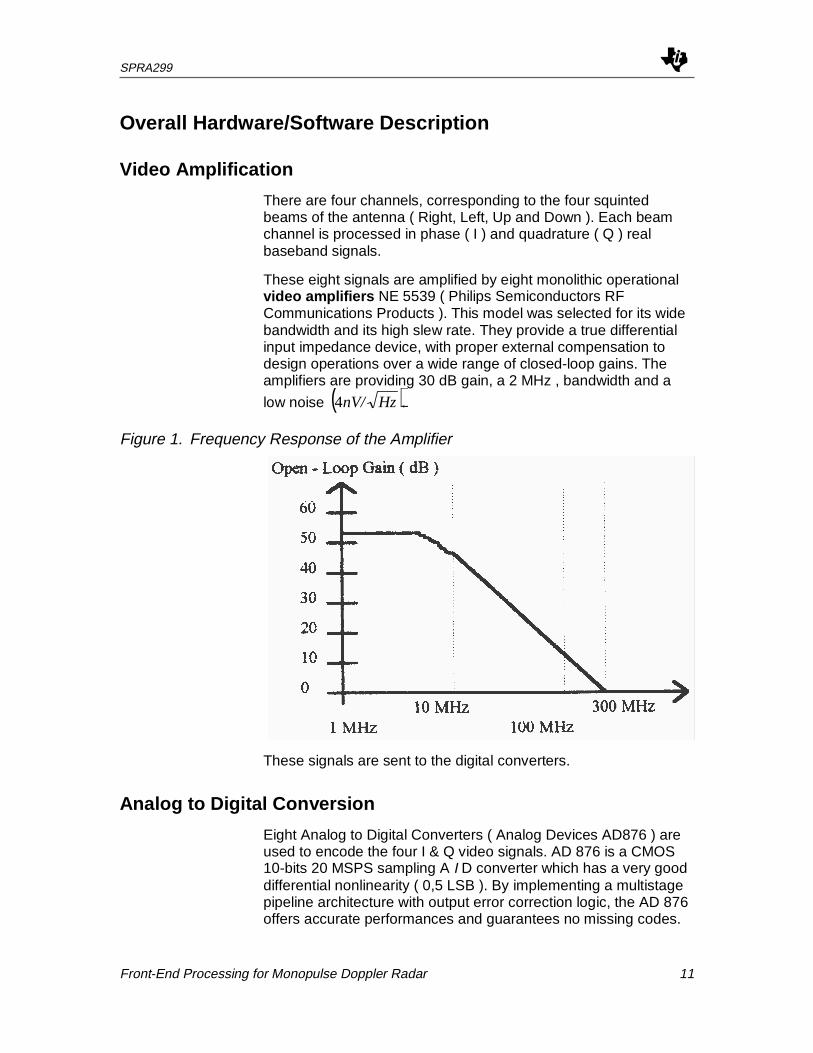
These eight signals are amplified by eight monolithic operationalvideo amplifiers NE 5539 ( Philips Semiconductors RFCommunications Products ). This model was selected for its widebandwidth and its high slew rate. They provide a true differentialinput impedance device, with proper external compensation todesign operations over a wide range of closed-loop gains. Theamplifiers are providing 30 dB gain, a 2 MHz , bandwidth and a
low noise ( ).4 HznV/
Figure 1. Frequency Response of the Amplifier
These signals are sent to the digital converters.
Analog to Digital Conversion
Eight Analog to Digital Converters ( Analog Devices AD876 ) areused to encode the four I & Q video signals. AD 876 is a CMOS10-bits 20 MSPS sampling A I D converter which has a very gooddifferential nonlinearity ( 0,5 LSB ). By implementing a multistagepipeline architecture with output error correction logic, the AD 876offers accurate performances and guarantees no missing codes.
SPRA299
12 Front-End Processing for Monopulse Doppler Radar
The sampling frequency is set to 2 MHz ( 500 ns). The RadarManager ( project C ) delivers the clock ( 2 Mhz) and theconversion window ( signal named PRI ).
This signal has to respect some time rules:
� The number of samples could be 17 to 47 ( according to 16range bins, plus 1 to 31 taps for the Digital Filter.
� PRI must be low between 8,5 µs ( 17 samples ) and 23,5 µs( 47 samples ).
� PRI is periodic ( 50 µs to 100 µs ) according to the repetitionused by the radar. This value is computed by the RadarManager.
An octal buffer and line driver with 3-states outputs ( SN 74F244from Texas Instrument ) is used to latch the ADC outputs. Thiscomponent is interesting because of its fast logic ( switchingcharacteristics of typically 4 ns ). That means that the outputs canbe stopped quickly, whereas the switching of the ADC isapproximately 25 ns.
The data are converted 10 bits to 16 bits to fit the digital externaldata bus by copying out the MSB bit ( d9 ) to the bits d9 up to d15.
Input Interface Between DSP and ADC
There are four DSP ( TMS 320 C50 ), one per antenna beam,each interfaced with two ADC ( refer to diagram Appendices Band C ). Numerical Data are available by addressing the ADC asexternal memory. The addresses are 2C60h ( channel Q ) and2C62h ( channel I ), chosen from the Data Memory Map.
When the PRI is low, the DSP takes in the samples, with thefollowing instructions forming an interruption subroutinedeclenched by interruption IT1 ( low active state during at least 3consecutive machine cycles ):
BLDD # 2C60h, AR1 ;AR1 initialised in the main with 0100hBLDD # 2C62h, AR2 ;AR2 initialised in the main with 0200h#AR1 ++# AR2 ++
ADC Data reading is illustrated by Figure 2.
SPRA299
Front-End Processing for Monopulse Doppler Radar 13
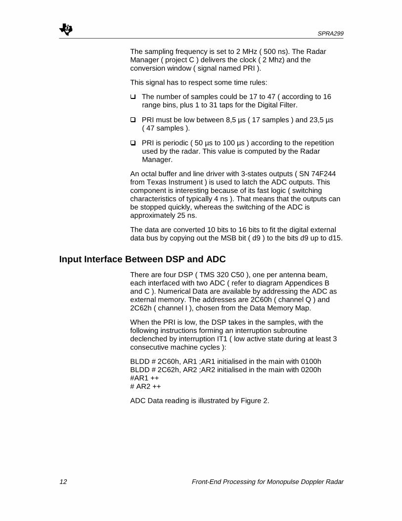
Figure 2. Addressing the ADC
As the DSP is running with interruption IT1, the signal which willactivate the interruption during at least 3 consecutive machinecycles have to be chosen. The input of this interruption is a lowactive state and as the frequency of new samples is 2 Mhz, acombination between the signal PRI and the 2 Mhz clock, whichare synchroned because issued from the same Master Clock (project C ), can be used as IT1.
Digital Pulse Compression
General Description
The aims of the Digital Pulse Compression system ( DPC ) are toreduce the peak transmitted power and the voltage / current ratio,keeping a good range resolution.
The DPC consists of a digital correlation between:
� the received signal from the target, corresponding to a delayedimage of the transmitted waveform, modified by the Dopplereffect.
� the reference code matched to the transmitter sequence.
This lead to the single pulse ambiguity which is the outputamplitude as a 3d surface function of the range delay and theDoppler shift.
The samples used by the DPC are coming from the two ADCwhich operate on the received signal at a 500 ns period ( rangeresolution of 75 meters ). The Digital Correlation is performed on apart of this received video signal, according to the length of thereference code chosen ( called Lx code ). There are nine differentcodes used in the DPC system which length may vary from 1 upto 31 coefficients. The number of Digital Correlation outputs isequal to 16 ( 16 range bins ). The number of samples taken fromthe ADC will be included between 17 ( 1 + 16 ) up to 47( 31 + 16 ).
SPRA299
14 Front-End Processing for Monopulse Doppler Radar
The only information needed to calculate the DPC is the length ofthe reference code. This information is given by the RadarManager ( project C ), using the serial port communicationinterface.
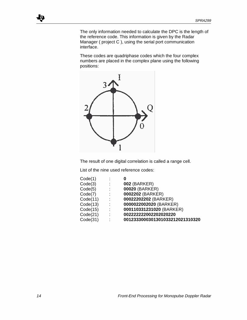
These codes are quadriphase codes which the four complexnumbers are placed in the complex plane using the followingpositions:
The result of one digital correlation is called a range cell.
List of the nine used reference codes:
Code(1) : 0Code(3) : 002 (BARKER)Code(5) : 00020 (BARKER)Code(7) : 0002202 (BARKER)Code(11) : 00022202202 (BARKER)Code(13) : 0000022002020 (BARKER)Code(15) : 000110331231020 (BARKER)Code(21) : 002222222002202020220Code(31) : 0012333000301301033212021310320
SPRA299
Front-End Processing for Monopulse Doppler Radar 15
Overview of the Calculation
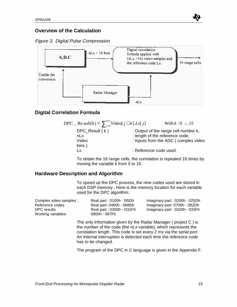
Figure 3. Digital Pulse Compression
Digital Correlation Formula
150 :k With jLxkjVideoksultDPCnLx
j→+= ∑ =0
][].[)(Re_
DPC_Result ( k ) : Output of the range cell number k.nLx : length of the reference code.Video : Inputs from the ADC ( complex videobins ).Lx : Reference code used.
To obtain the 16 range cells, the correlation is repeated 16 times bymoving the variable k from 0 to 15.
Hardware Description and Algorithm
To speed up the DPC process, the nine codes used are stored ineach DSP memory . Here is the memory location for each variableused for the DPC algorithm:
Complex video samples : Real part : 0100h - 0l5Dh Imaginary part : 0200h - 025DhReference codes Real part: 0460h - 068Dh Imaginary part: 0700h - 092DhDPC results Real part : 0300h - O31Fh Imaginary part : 0320h - 033FhWorking variables: 0800h - 087Fh
The only information given by the Radar Manager ( project C ) isthe number of the code (the nLx variable), which represents thecorrelation length. This code is set every 2 ms via the serial port.An internal interruption is detected each time the reference codehas to be changed.
The program of the DPC in C language is given in the Appendix F.
SPRA299
16 Front-End Processing for Monopulse Doppler Radar
The 16 range cells given by the DPC algorithm are the elementaryinformations taken from the received signal on a PRI period. Theywill be associated with the Doppler filtering which will give theinformation necessary to track the detected target.
After having simulated the algorithm in C language and incomparison with the arrays of calculation, the reason for orderingthe data in memory and the importance of the shift implementedby the LTD instruction can be seen. To optimise real time andspeed calculation, the for loop can be replaced by a shift of thedata in memory (LTD). This instruction loads the T register withthe contents of the address, adds the result of the previousmultiply to the accumulator and shifts the data to the next higheraddress in data memory. Associated with MPY ( multiplication ofthe contents of the T register with the contents of the address ),the calculations are optimised for real time specifications.
ZAC ;Zero the accumulatorLTD VideoQ ;CoefR . DopplerMPY LxQLTS Videol ;CoefQ . DopplerQ - CoefI . DopplerIMPY LxlDMOV Videol
These instructions can be repeated nLx times with the RPTBinstruction, improving the time for calculations.
Doppler Processing
The Doppler Processing is used to reduce the bandwidth (coherent integration ) and to reject fixed echoes. It is applied onthe 16 complex range bins calculated by the Pulse Compressor. Itcorresponds to a complex coefficients BandPass Filter ( BPF ),centered around a specific Doppler frequency.
This filter is used 3 times, with 3 different center frequencies, onthe 16 * 2 inputs ( real and imaginary parts ). So, the outputscontained 16 * 2 * 3 values. These 3 filters are Digital order onefilters, based on a relationship between the input sequenceDPC_Result ( n ) and the output sequence Doppler ( n ).
Calculations
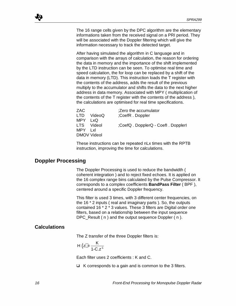
The Z transfer of the three Doppler filters is:
Each filter uses 2 coefficients : K and C.
� K corresponds to a gain and is common to the 3 filters.
( )H zK
1-C.z-1=
SPRA299
Front-End Processing for Monopulse Doppler Radar 17
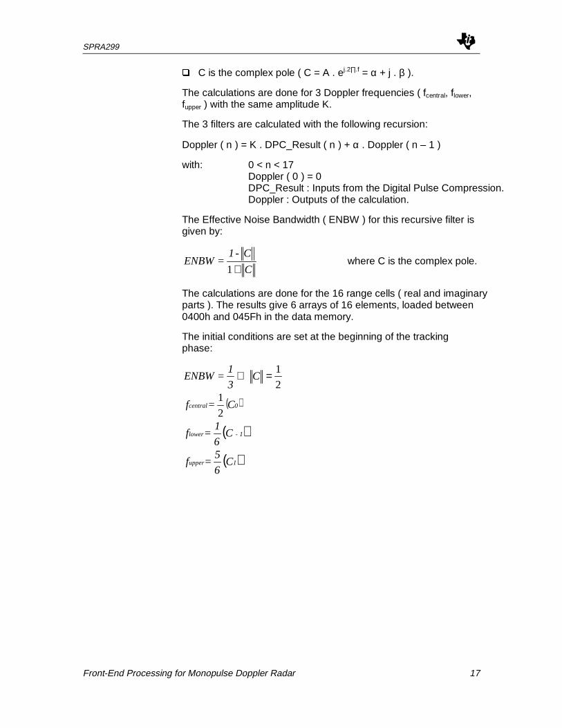
� C is the complex pole ( C = A . ej.2∏.f = α + j . β ).
The calculations are done for 3 Doppler frequencies ( fcentral, flower,fupper ) with the same amplitude K.
The 3 filters are calculated with the following recursion:
Doppler ( n ) = K . DPC_Result ( n ) + α . Doppler ( n – 1 )
with: 0 < n < 17Doppler ( 0 ) = 0DPC_Result : Inputs from the Digital Pulse Compression.Doppler : Outputs of the calculation.
The Effective Noise Bandwidth ( ENBW ) for this recursive filter isgiven by:
C
C-1=ENBW
+1 where C is the complex pole.
The calculations are done for the 16 range cells ( real and imaginaryparts ). The results give 6 arrays of 16 elements, loaded between0400h and 045Fh in the data memory.
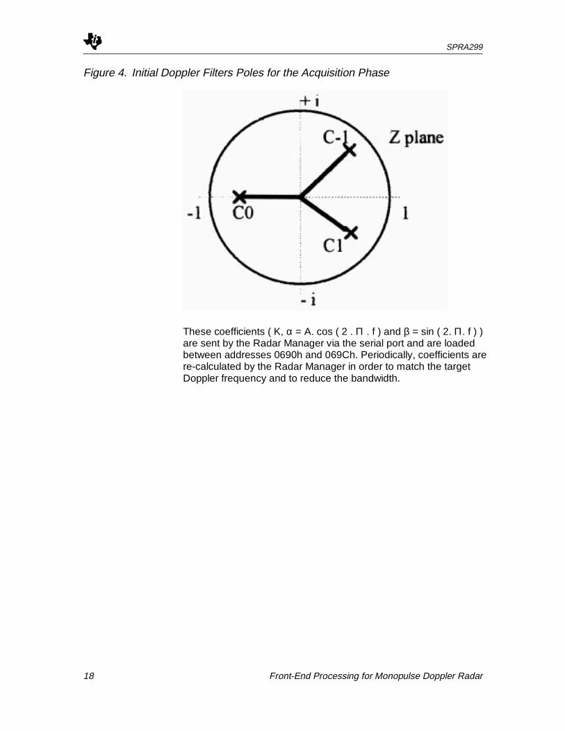
The initial conditions are set at the beginning of the trackingphase:
2
1=⇒ C3
1=ENBW
( )0 central C =f2
1
( )1-lower C6
1 =f
( )1upper C6
5 =f
SPRA299
18 Front-End Processing for Monopulse Doppler Radar
Figure 4. Initial Doppler Filters Poles for the Acquisition Phase
These coefficients ( K, α = A. cos ( 2 . Π . f ) and β = sin ( 2. Π. f ) )are sent by the Radar Manager via the serial port and are loadedbetween addresses 0690h and 069Ch. Periodically, coefficients arere-calculated by the Radar Manager in order to match the targetDoppler frequency and to reduce the bandwidth.

SPRA299
Front-End Processing for Monopulse Doppler Radar 19
Figure 5. Poles of 3 Narrow Filters Around the Central Doppler Frequency Duringthe Tracking Phase (Example)
The central frequency is deduced from the trajectory. The radarmanager ( project C ) computes the estimated and smoothedDoppler coefficients.
C Program
The program in C language is specified before writing the ASMprogram and is given in the Appendix F. It can help to optimise theASM program by taking advantages ( for execution time and datamemory ) of the TMS C50 features. To maximise the real timecalculations, the same instructions than in the DPC program areused : LTD, MPY, DMOV and RPTB.
Approximate Modulus
Magnitudes of previous results are calculated and transmitted tothe Digital Tracker.
The following approximate formula is used:
M=I Q +12
I Q+ −

SPRA299
20 Front-End Processing for Monopulse Doppler Radar
ABS is available in the TMS320C50 instruction set. This formula iscomputed on the 16 range cells * 2 ( Q and I parts ) * 3 Dopplerfor each beam. Results are corresponding to 16 range cells * 3Dopplers * 4 beams.
Output Interface with the Digital Tracker
To share the 16 * 3 * 4 values with the Tracker, four Dual PortRAM are used. According to the documentation from IntegratedDevice Technology ( IDT ), the Dual Port RAM allows 2independent devices to have simultaneous read and write accessto the same memory. This allows the 2 devices to communicatewith each other by passing data through the common memory.So, a dual-port memory has 2 sets of address, data and read /write control signals, each of them access the same set ofmemory cells. The product 7133 from IDT allows a memory of2Kword on 16 bits. With a good access time, the only problemabout using this chip is about writing into the same cell at thesame time. But as this project only writes the data and as theTracker has only to read the data at a different time, the problemnever occurs.
This memory has been declared between addresses 2C00h and2C5Fh, according to the memory map ( external device ).
Communication with the Radar Manager
By the use of a serial link between this project and the RadarManager ( project C ), a refresh of global variables is proceeded.These global variables are used for the 2 digital filters which havebeen presented precedently. The maximum operating frequency ofthe serial port while using internal clocks is the frequency ofCLKOUT divided by four ( 5 Mbit/s at 50 ns ; 7,14 Mbit/s at 35 ns ).
Architecture
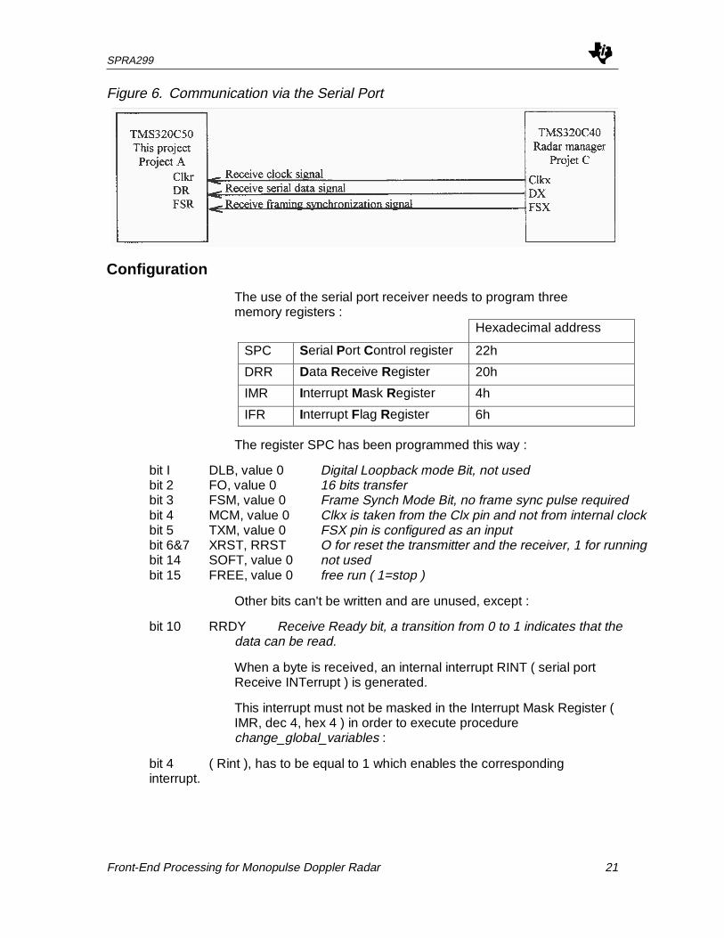
The signals CLKR ( Receive Clock Signal ), DR ( Receive serialData signal ), FSR ( Receive Framing synchronisation Signal ) ofour DSP's are connected to the Radar Manager' DSP ( project C ).
SPRA299
Front-End Processing for Monopulse Doppler Radar 21
Figure 6. Communication via the Serial Port
Configuration
The use of the serial port receiver needs to program threememory registers :
Hexadecimal address
SPC Serial Port Control register 22h
DRR Data Receive Register 20h
IMR Interrupt Mask Register 4h
IFR Interrupt Flag Register 6h
The register SPC has been programmed this way :
bit I DLB, value 0 Digital Loopback mode Bit, not usedbit 2 FO, value 0 16 bits transferbit 3 FSM, value 0 Frame Synch Mode Bit, no frame sync pulse requiredbit 4 MCM, value 0 Clkx is taken from the Clx pin and not from internal clockbit 5 TXM, value 0 FSX pin is configured as an inputbit 6&7 XRST, RRST O for reset the transmitter and the receiver, 1 for runningbit 14 SOFT, value 0 not usedbit 15 FREE, value 0 free run ( 1=stop )
Other bits can't be written and are unused, except :
bit 10 RRDY Receive Ready bit, a transition from 0 to 1 indicates that thedata can be read.
When a byte is received, an internal interrupt RINT ( serial portReceive INTerrupt ) is generated.
This interrupt must not be masked in the Interrupt Mask Register (IMR, dec 4, hex 4 ) in order to execute procedurechange_global_variables :
bit 4 ( Rint ), has to be equal to 1 which enables the correspondinginterrupt.
SPRA299
22 Front-End Processing for Monopulse Doppler Radar
Global Variables Needed for Digital Calculations
The first filter ( Digital Pulse Compression ) only needs onevariable : a number between 1 and 9 which corresponds to thechoice of the Lx code ( 9 different codes ).
� ‘L’ : integer 16 bits numero of LX code.
The second filter ( Doppler Processing ) computes differentvariables :
� ‘K’ : integer ( 16 bits ) Amplitude coefficient of thefilter.
� ‘i’, ‘c’, ‘s’ :integers ( 16 bits ) Real part ( α ) for the inferior,central and superiorfrequencies.
� ‘I’ ‘C’ ‘S’ :integers ( 16 bits ) Imaginary part ( β ) for theinferior ,central and superiorfrequencies.
These are the only variables that this project needs for thecalculations.
Transmission Protocol
Two different methods have been studied:
� The Radar Manager (project C) transmits only the variablesthat need to be changed (for example : K, 1200, i, 1300, C,2400). The main advantage of this method consists in the factthat the Radar Manager doesn't need to transmit the eightvariables. But it needs a lot of cycles at the reception for thetests to recognise the variables.
� An other method consists to transmit the 8 words (16 bits).When the receive buffer is full, the integer is placed into thecorresponding variable. This method has been retainedbecause of its speed : all the variables are sent every 2 ms.
The starting reception is detected by an interrupt signal. Thissignal is generated when the first integer is received. Then theprocedure global_variables is executed.

SPRA299
Front-End Processing for Monopulse Doppler Radar 23
Figure 7. Reception Diagram
SPRA299
24 Front-End Processing for Monopulse Doppler Radar
Performances and Conclusion
This section concerns the effects of the 2 filters on filterperformances. Indeed, some features of filters include phasecharacteristics, stability and coefficient quantization effects. Animportant consideration is the stability of the filter. The DigitalPulse Compression is inherently stable (i.e., a bounded inputalways produces a bounded output ). On the other hand, theDoppler Processing may or may not be stable, depending on thelocation of the pole of the filter.
Digital filters are designed with the assumption that the filter willbe implemented on an infinite precision device. However, as allprocessors are of finite precision, it is necessary to approximatethe ‘ ideal ‘ filter coefficients. This approximation introducescoefficients quantization error. The net result due to imprecisecoefficient representations is a deviation of the resultant filterfrequency response from the ideal one.
Another problem in implementing a digital filter is the quantizationerror due to the finite wordlength effect in the hardware. Source oferror arising from the use of finite wordlength include the following :
� I I 0 signal quantization ( ADC conversion ).
� Filter coefficient quantization.
� Correlated roundoff noise.
� Dynamic range constraints.
The advantages of using digital filters over their Analogcounterparts are:
� high reliability.
� high accuracy.
� no effect of component drift on system.
� component tolerance not critical.
� Ease for changing filter parameters.
The 16-bit coefficients and the 32-bit accumulator of the TMS 320processors help minimise the quantization effects. Specialinstructions also help to overcome problems in the accumulator.These features, in addition to a powerful instruction set and a fastclock timing, make the TMS320C50 ideal programmableprocessors for our application.
SPRA299
Front-End Processing for Monopulse Doppler Radar 25
In the worst case of the PRI, there is only 50 µs ( shortest periodof the PRI ) - 23,5 µs ( 47 samples of 500 ns each ) = 26,5 µs forthe digital calculations, before the next samples. Indeed, the radarmust work in real time, so it can't memorise and calculate later.This is the main reason for using 4 DSP C50 in parallel : the 47 * 4samples ( worst case ) can't be loaded and 1 * 4 + 3 * 4 + 1 * 4 =20 algorithms can't be processed in real time. With 4 DSP, wehave only 47 samples and 1 + 3 + 1 = 5 algorithms to processthem one after the others and in the same time than the first case.Indeed, the first case needs to compute with 45 MIPS whereas thesecond one needs only 15 MIPS per DSP. And DSP TMS 320C50 allows a 35 I 50 ns single-cycle fixed-point instructionexecution time ( 28.6 / 20 MIPS).
This project demonstrates that a typical processing of MonopulseDoppler Radar implemented on only 4 chips, realising 16 rangecells ( 500 ns ) * 3 complex Doppler filters * 4 beams is equivalentto 4 * 15 MIPS. It represents 75 % of the time possibilities offeredby the 4 DSP TMS320C50.

SPRA299
26 Front-End Processing for Monopulse Doppler Radar
Appendices
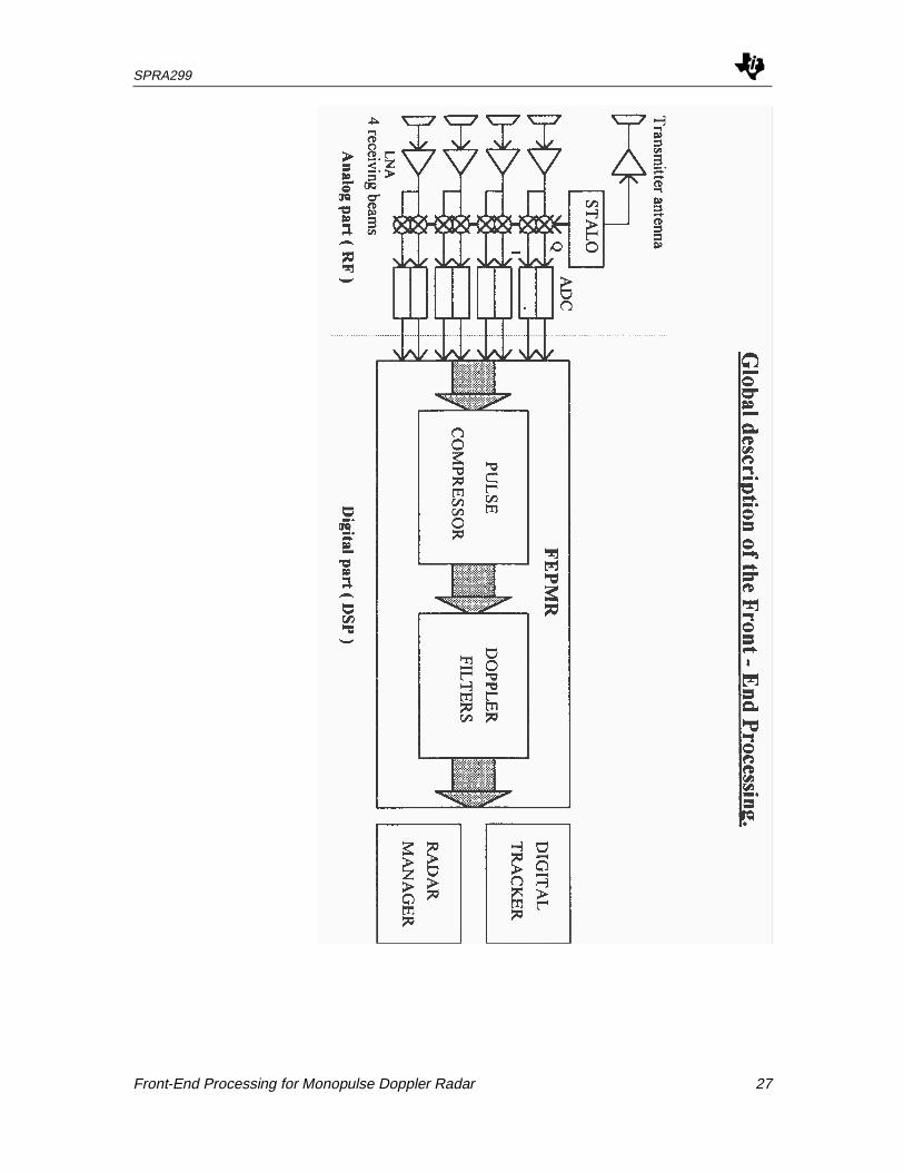
General description of the Front-End Processing. A
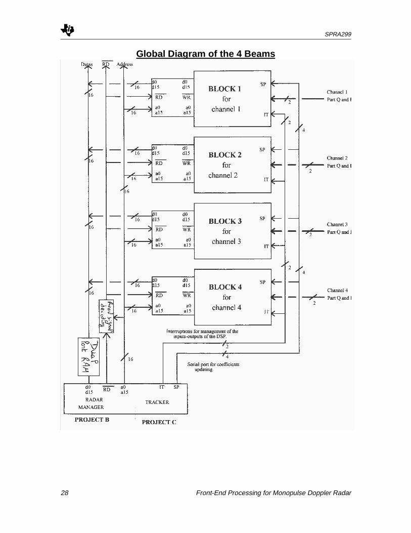
Global diagram of the 4 beams. B
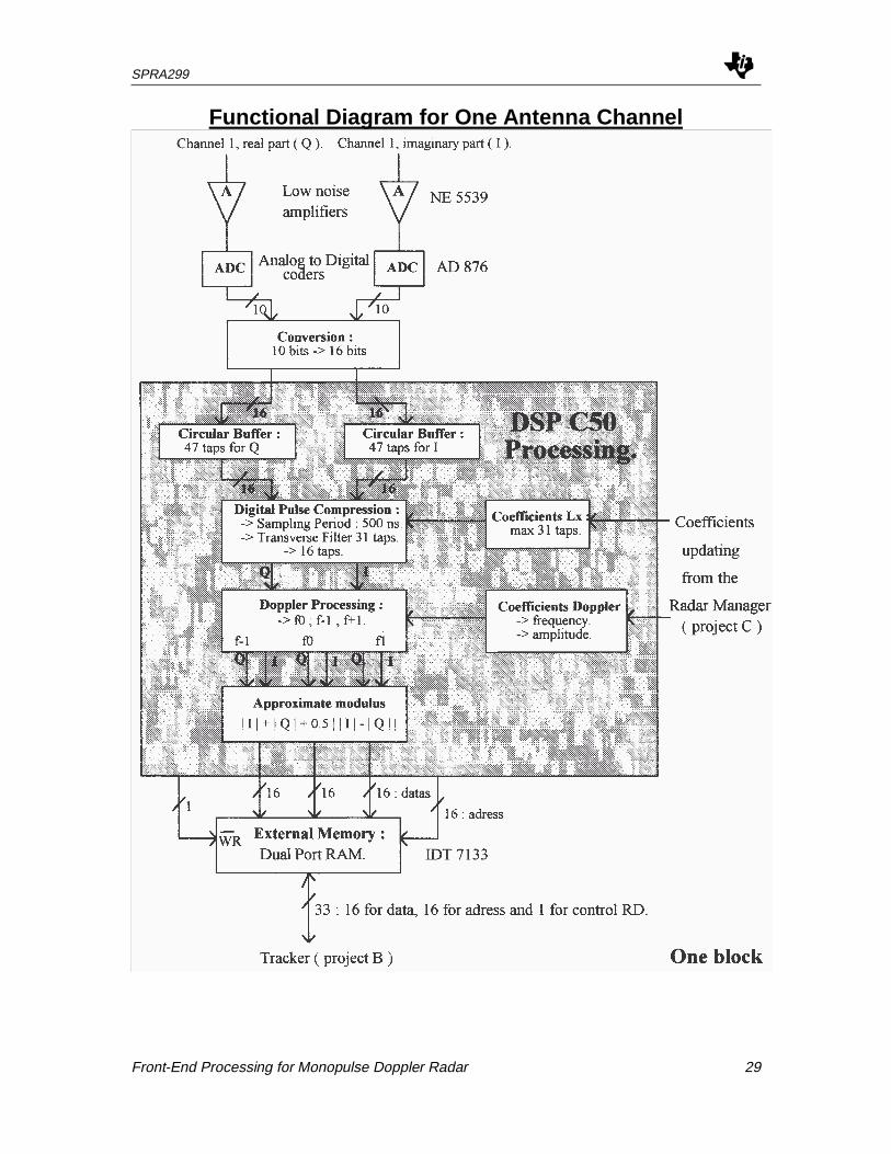
Functional diagram for one antenna channel. C
Electrical diagram for one channel. D
Memory allocation. E
C program for simulation. F
C and ASM programs for the serial communication. J
SPRA299
Front-End Processing for Monopulse Doppler Radar 27
SPRA299
28 Front-End Processing for Monopulse Doppler Radar
Global Diagram of the 4 Beams
SPRA299
Front-End Processing for Monopulse Doppler Radar 29
Functional Diagram for One Antenna Channel

SPRA299
30 Front-End Processing for Monopulse Doppler Radar
SPRA299
Front-End Processing for Monopulse Doppler Radar 31
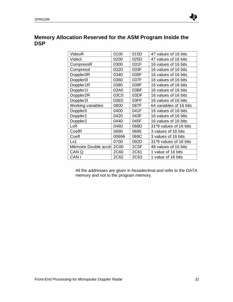
Memory Allocation Reserved for the ASM Program Inside theDSP
VideoR 0100 015D 47 values of 16 bitsVideol 0200 025D 47 values of 16 bitsCompressR 0300 031F 16 values of 16 bitsCompressl 0320 033F 16 values of 16 bitsDoppler0R 0340 035F 16 values of 16 bitsDoppler0l 0360 037F 16 values of 16 bitsDoppler1R 0380 039F 16 values of 16 bitsDoppler1I 03A0 03BF 16 values of 16 bitsDoppler2R 03C0 03DF 16 values of 16 bitsDoppler2l 03E0 03FF 16 values of 16 bitsWorking variables 0800 087F 64 variables of 16 bitsDoppler0 0400 041F 16 values of 16 bitsDoppler1 0420 043F 16 values of 16 bitsDoppler2 0440 045F 16 values of 16 bitsLxR 0460 068D 31*9 values of 16 bitsCoefR 0690 0695 3 values of 16 bitsCoefI 00696 069C 3 values of 16 bitsLx1 0700 092D 31*9 values of 16 bitsMémoire Double accès2C00 2C5F 48 values of 16 bitsCAN Q 2C60 2C61 1 value of 16 bitsCAN I 2C62 2C63 1 value of 16 bits
All the addresses are given in hexadecimal and refer to the DATAmemory and not to the program memory.
SPRA299
32 Front-End Processing for Monopulse Doppler Radar
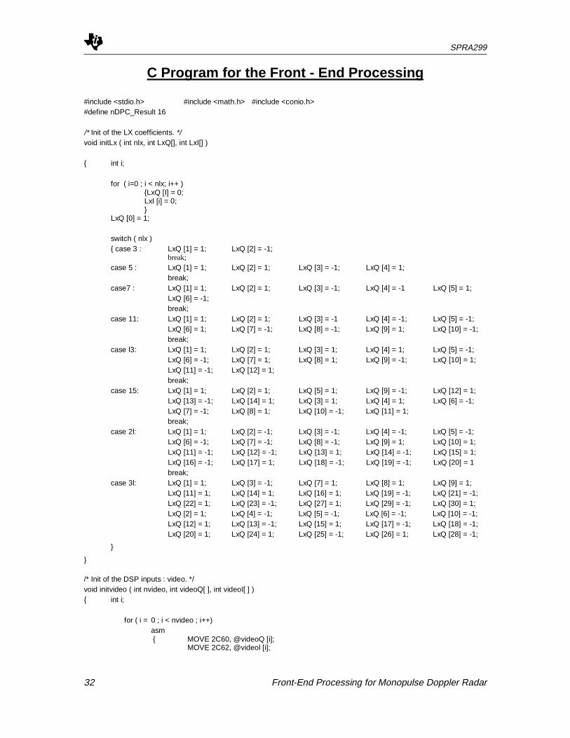
C Program for the Front - End Processing
#include <stdio.h> #include <math.h> #include <conio.h>#define nDPC_Result 16
/* Init of the LX coefficients. */void initLx ( int nlx, int LxQ[], int LxI[] )
{ int i;
for ( i=0 ; i < nlx; i++ ){LxQ [I] = 0;LxI [i] = 0;}
LxQ [0] = 1;
switch ( nlx ){ case 3 : LxQ [1] = 1; LxQ [2] = -1;
break;case 5 : LxQ [1] = 1; LxQ [2] = 1; LxQ [3] = -1; LxQ [4] = 1;
break;case7 : LxQ [1] = 1; LxQ [2] = 1; LxQ [3] = -1; LxQ [4] = -1 LxQ [5] = 1;
LxQ [6] = -1;break;
case 11: LxQ [1] = 1; LxQ [2] = 1; LxQ [3] = -1 LxQ [4] = -1; LxQ [5] = -1;LxQ [6] = 1; LxQ [7] = -1; LxQ [8] = -1; LxQ [9] = 1; LxQ [10] = -1;break;
case l3: LxQ [1] = 1; LxQ [2] = 1; LxQ [3] = 1; LxQ [4] = 1; LxQ [5] = -1;LxQ [6] = -1; LxQ [7] = 1; LxQ [8] = 1; LxQ [9] = -1; LxQ [10] = 1;LxQ [11] = -1; LxQ [12] = 1;break;
case 15: LxQ [1] = 1; LxQ [2] = 1; LxQ [5] = 1; LxQ [9] = -1; LxQ [12] = 1;LxQ [13] = -1; LxQ [14] = 1; LxQ [3] = 1; LxQ [4] = 1; LxQ [6] = -1;LxQ [7] = -1; LxQ [8] = 1; LxQ [10] = -1; LxQ [11] = 1;break;
case 2l: LxQ [1] = 1; LxQ [2] = -1; LxQ [3] = -1; LxQ [4] = -1; LxQ [5] = -1;LxQ [6] = -1; LxQ [7] = -1; LxQ [8] = -1; LxQ [9] = 1; LxQ [10] = 1;LxQ [11] = -1; LxQ [12] = -1; LxQ [13] = 1; LxQ [14] = -1; LxQ [15] = 1;LxQ [16] = -1; LxQ [17] = 1; LxQ [18] = -1; LxQ [19] = -1; LxQ [20] = 1break;
case 3l: LxQ [1] = 1; LxQ [3] = -1; LxQ [7] = 1; LxQ [8] = 1; LxQ [9] = 1;LxQ [11] = 1; LxQ [14] = 1; LxQ [16] = 1; LxQ [19] = -1; LxQ [21] = -1;LxQ [22] = 1; LxQ [23] = -1; LxQ [27] = 1; LxQ [29] = -1; LxQ [30] = 1;LxQ [2] = 1; LxQ [4] = -1; LxQ [5] = -1; LxQ [6] = -1; LxQ [10] = -1;LxQ [12] = 1; LxQ [13] = -1; LxQ [15] = 1; LxQ [17] = -1; LxQ [18] = -1;LxQ [20] = 1; LxQ [24] = 1; LxQ [25] = -1; LxQ [26] = 1; LxQ [28] = -1;
}
}
/* Init of the DSP inputs : video. */void initvideo ( int nvideo, int videoQ[ ], int videoI[ ] ){ int i;
for ( i = 0 ; i < nvideo ; i++)asm{ MOVE 2C60, @videoQ [i];
MOVE 2C62, @videol [i];
SPRA299
Front-End Processing for Monopulse Doppler Radar 33
}}
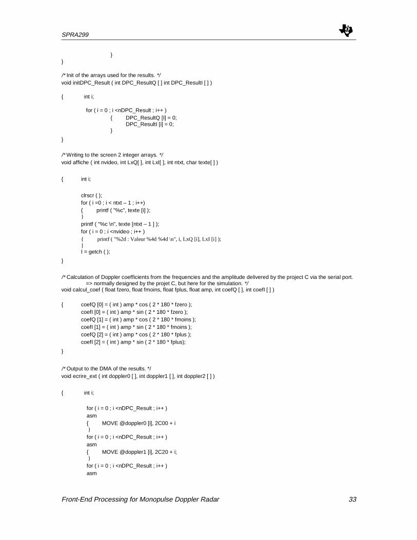
/* Init of the arrays used for the results. */void initDPC_Result ( int DPC_ResultQ [ ] int DPC_ResultI [ ] )
{ int i;
for ( i = 0 ; i <nDPC_Result ; i++ ){ DPC_ResultQ [I] = 0;
DPC_ResultI [i] = 0;}
}
/* Writing to the screen 2 integer arrays. */void affiche ( int nvideo, int LxQ[ ], int LxI[ ], int ntxt, char texte[ ] )
{ int i;
clrscr ( );for ( i =0 ; i < ntxt – 1 ; i++){ printf ( "%c", texte [i] );}printf ( "%c \n", texte [ntxt – 1 ] );for ( i = 0 ; i <nvideo ; i++ ){ printf ( "%2d : Valeur %4d %4d \n", i, LxQ [i], LxI [i] );}I = getch ( );
}
/* Calculation of Doppler coefficients from the frequencies and the amplitude delivered by the project C via the serial port.=> normally designed by the projet C, but here for the simulation. */
void calcul_coef ( float fzero, float fmoins, float fplus, float amp, int coefQ [ ], int coefI [ ] )
{ coefQ [0] = ( int ) amp * cos ( 2 * 180 * fzero );coefI [0] = ( int ) amp * sin ( 2 * 180 * fzero );coefQ [1] = ( int ) amp * cos ( 2 * 180 * fmoins );coefI [1] = ( int ) amp * sin ( 2 * 180 * fmoins );coefQ [2] = ( int ) amp * cos ( 2 * 180 * fplus );coefI [2] = ( int ) amp * sin ( 2 * 180 * fplus);
}
/* Output to the DMA of the results. */void ecrire_ext ( int doppler0 [ ], int doppler1 [ ], int doppler2 [ ] )
{ int i;
for ( i = 0 ; i <nDPC_Result ; i++ )asm{ MOVE @doppler0 [i], 2C00 + i}for ( i = 0 ; i <nDPC_Result ; i++ )asm{ MOVE @doppler1 [i], 2C20 + i;}for ( i = 0 ; i <nDPC_Result ; i++ )asm
SPRA299
34 Front-End Processing for Monopulse Doppler Radar
{ MOVE @doppler2 [i], 2C40 + i;}
}
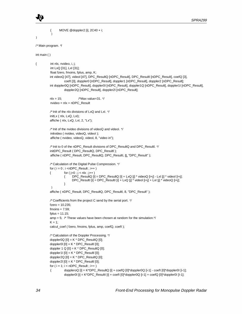
/* Main program. */
int main ( )
{ int nlx, nvideo, i, j;int LxQ [31], LxI [31];float fzero, fmoins, fplus, amp, K;int videoQ [47], videol [47], DPC_ResultQ [nDPC_Result], DPC_ResultI [nDPC_Result], coefQ [3],
coefI [3], doppler0 [nDPC_Result], doppler1 [nDPC_Result], doppler2 [nDPC_Result];int doppler0Q [nDPC_Result], doppler0I [nDPC_Result], doppler1Q [nDPC_Result], doppler1I [nDPC_Result],
doppler2Q [nDPC_Result], doppler2l [nDPC_Result];
nlx = 15; /*Max value=31. */nvideo = nlx + nDPC_Result
/* Init of the nlx divisions of LxQ and LxI. */initLx ( nlx, LxQ, LxI);affiche ( nlx, LxQ, LxI, 2, "Lx");
/* Init of the nvideo divisions of videoQ and videoI. */initvideo ( nvideo, videoQ, videoI );affiche ( nvideo, videoQ, videol, 8, "video in");
/* Init to 0 of the nDPC_Result divisions of DPC_ResultQ and DPC_Resultl. */initDPC_Result ( DPC_ResultQ, DPC_Resultl );affiche ( nDPC_Result, DPC_ResultQ, DPC_ResultI, 8, "DPC_Result" );
/* Calculation of the Digital Pulse Compression. */for ( i = 0 ; i <nDPC_Result ; i++ ){ for ( j=0 ; j < nlx ; j++ )
{ DPC_ResultQ [i] = DPC_ResultQ [i] + LxQ [j] * videoQ [i+j] - LxI [j] * videol [i+j]; DPC_ResultI [i] = DPC_ResultI [i] + LxQ [j] * videol [i+j] + LxI [j] * videoQ [i+j];}
}affiche ( nDPC_Result, DPC_ResultQ, DPC_Resultl, 8, "DPC_Result" );
/* Coefficients from the project C send by the serial port. */fzero = 10.235;fmoins = 7.59;fplus = 11.15;amp = 5; /* These values have been chosen at random for the simulation.*/K = 1;calcul_coef ( fzero, fmoins, fplus, amp, coefQ, coefI );
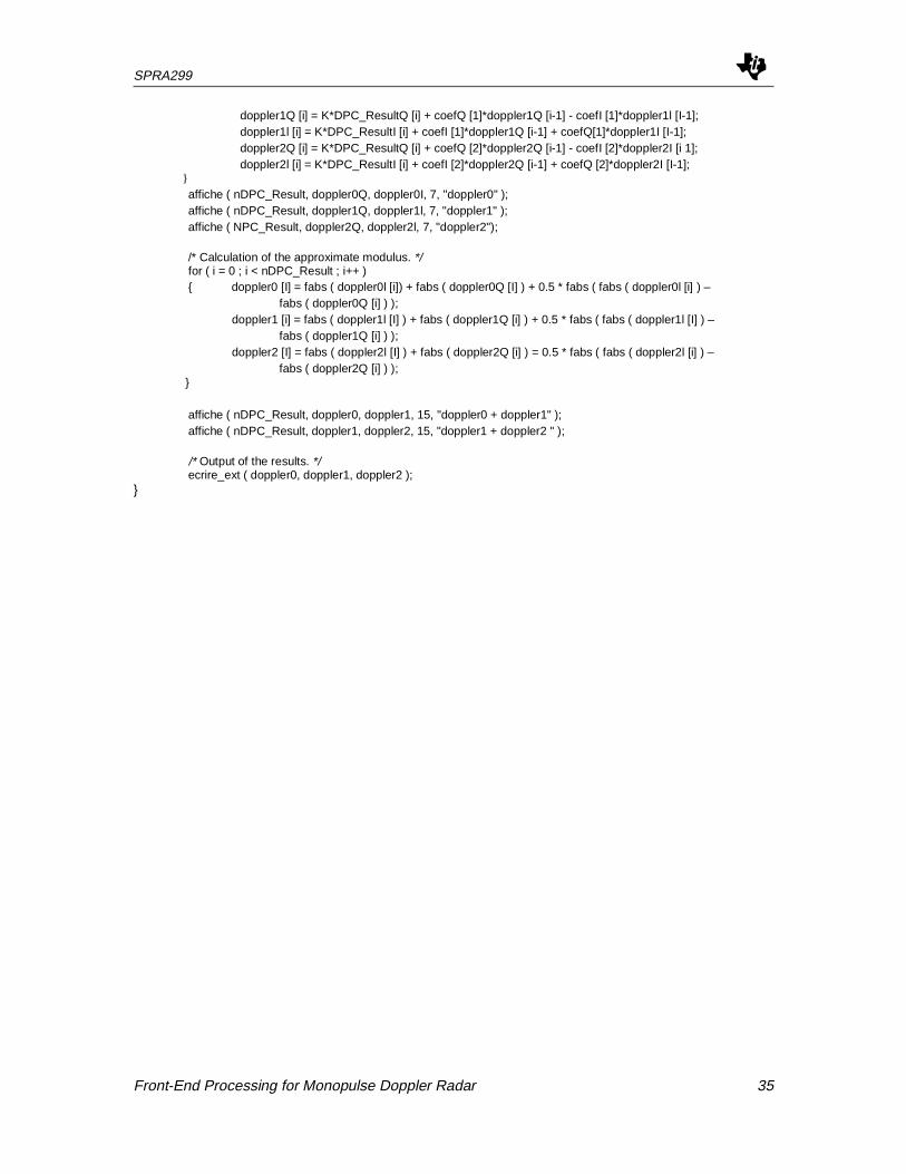
/* Calculation of the Doppler Processing. */doppler0Q [0] = K * DPC_ResultQ [0];doppler0l [0] = K * DPC_Resultl [0];doppler 1 Q [0] = K * DPC_ResultQ [0];doppler1I [0] = K * DPC_Resultl [0];doppler2Q [0] = K * DPC_ResultQ [0];doppler2l [0] = K * DPC_Resultl [0];for ( i = 1; i < nDPC_Result ; i++ ){ doppleroQ [i] = K*DPC_ResultQ [i] + coefQ [0]*doppler0Q [i-1] - coefI [0]*doppler0I [i-1];
doppler0l [i] = K*DPC_ResultI [i] + coefI [0]*doppler0Q [i-1] + coefQ [0]*doppler0I [I-1];
SPRA299
Front-End Processing for Monopulse Doppler Radar 35
doppler1Q [i] = K*DPC_ResultQ [i] + coefQ [1]*doppler1Q [i-1] - coefI [1]*doppler1l [I-1];doppler1l [i] = K*DPC_ResultI [i] + coefI [1]*doppler1Q [i-1] + coefQ[1]*doppler1I [I-1];doppler2Q [i] = K*DPC_ResultQ [i] + coefQ [2]*doppler2Q [i-1] - coefI [2]*doppler2I [i 1];doppler2l [i] = K*DPC_ResultI [i] + coefI [2]*doppler2Q [i-1] + coefQ [2]*doppler2I [I-1];
}affiche ( nDPC_Result, doppler0Q, doppler0I, 7, "doppler0" );affiche ( nDPC_Result, doppler1Q, doppler1l, 7, "doppler1" );affiche ( NPC_Result, doppler2Q, doppler2l, 7, "doppler2");
/* Calculation of the approximate modulus. */for ( i = 0 ; i < nDPC_Result ; i++ ){ doppler0 [I] = fabs ( doppler0l [i]) + fabs ( doppler0Q [I] ) + 0.5 * fabs ( fabs ( doppler0l [i] ) –
fabs ( doppler0Q [i] ) ); doppler1 [i] = fabs ( doppler1l [I] ) + fabs ( doppler1Q [i] ) + 0.5 * fabs ( fabs ( doppler1l [I] ) –
fabs ( doppler1Q [i] ) ); doppler2 [I] = fabs ( doppler2l [I] ) + fabs ( doppler2Q [i] ) = 0.5 * fabs ( fabs ( doppler2l [i] ) –
fabs ( doppler2Q [i] ) );}
affiche ( nDPC_Result, doppler0, doppler1, 15, "doppler0 + doppler1" );affiche ( nDPC_Result, doppler1, doppler2, 15, "doppler1 + doppler2 " );
/* Output of the results. */ecrire_ext ( doppler0, doppler1, doppler2 );
}

SPRA299
36 Front-End Processing for Monopulse Doppler Radar
C and Asm Programs for the Serial Communication
// Constant //#define nb_word_transfered 8#define begin_adr Ox9OOOh //9000h->9016h//#define adr_serial_buffer 32
// Global variables //L, K, I, c, s, I, C, S :integer;
// Reception of interruption Rint signales that the first byte is being transmitted //// Execution of procedure void change_global_variables (void) //
void change_global_variables (void)
// Local variables //integer *buffer_DRR;integer *register;
{register=04h; // adress of the register IMR //*register=0h; // inhibit interruptions //register=022h; // adress of the register SPC IIbuffer_DRR = adr_serial_buffer;K= *buffer_DRR;repeat until (*register & 04 00h == 1) // wait until bit RRDY==1; an integer is received //L= *buffer_DRR;repeat until (*register & 04 00h == 1) // wait until bit RRDY==1; an integer is received //i = *buffer_DRR;repeat until (*register & 04 00h == 1) // wait until bit RRDY==1; an integer is received //c= *buffer_DRR;repeat until (*register & 04 00h == 1) // wait until bit RRDY==1; an integer is received //s= *buffer_DRR;repeat until (*register & 04 00h == 1) // wait until bit RRDY==1; an integer is received //I= *buffer_DRR;repeat until (*register & 04 00h == 1) // wait until bit RRDY==1; an integer is received //C= *buffer_DRR;repeat until (*register & 04 00h == 1) // wait until bit RRDY==1; an integer is received //S= *buffer_DRR;register=04h; // adress of the register IMR //*register = 0l0h; // allow RINT interruption II
}
First, the vector has to be stored in the RAM:
LAMM change_global_variables ;ACC=ISR adressBACC ;Branch to ISR
In the main program there is an initialization part:
SPLK #0008h, SPC ; Set SP as CLK; frame sync receive; Set TXM=MCM=DLB=FO=0, FSM=1; and put SP into reset (XRST=RRST=0)
SPLK #00C8h, SPC ; Take SP out of reset, setup interrupts
SPRA299
Front-End Processing for Monopulse Doppler Radar 37
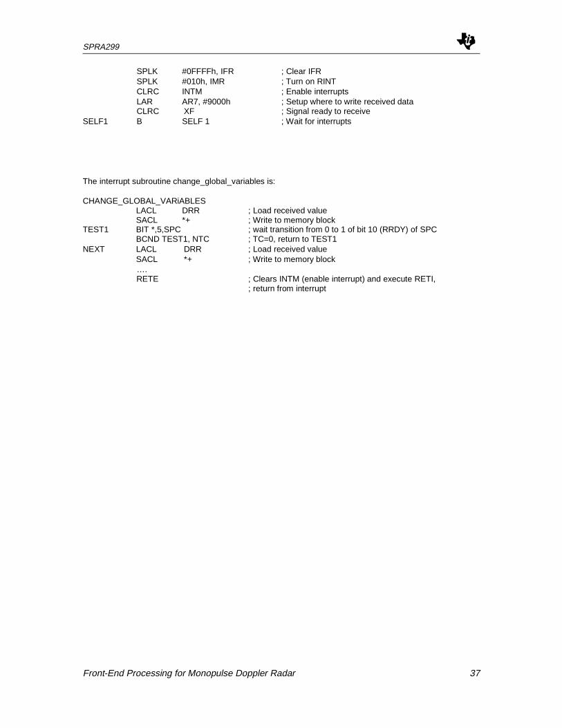
SPLK #0FFFFh, IFR ; Clear IFRSPLK #010h, IMR ; Turn on RINTCLRC INTM ; Enable interruptsLAR AR7, #9000h ; Setup where to write received dataCLRC XF ; Signal ready to receive
SELF1 B SELF 1 ; Wait for interrupts
The interrupt subroutine change_global_variables is:
CHANGE_GLOBAL_VARiABLESLACL DRR ; Load received valueSACL *+ ; Write to memory block
TEST1 BIT *,5,SPC ; wait transition from 0 to 1 of bit 10 (RRDY) of SPCBCND TEST1, NTC ; TC=0, return to TEST1
NEXT LACL DRR ; Load received valueSACL *+ ; Write to memory block….RETE ; Clears INTM (enable interrupt) and execute RETI,
; return from interrupt
SPRA299
38 Front-End Processing for Monopulse Doppler Radar
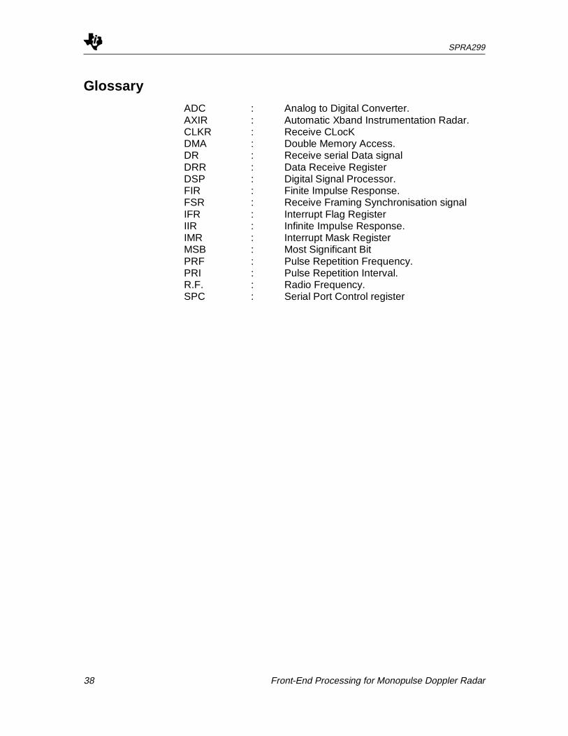
Glossary
ADC : Analog to Digital Converter.AXIR : Automatic Xband Instrumentation Radar.CLKR : Receive CLocKDMA : Double Memory Access.DR : Receive serial Data signalDRR : Data Receive RegisterDSP : Digital Signal Processor.FIR : Finite Impulse Response.FSR : Receive Framing Synchronisation signalIFR : Interrupt Flag RegisterIIR : Infinite Impulse Response.IMR : Interrupt Mask RegisterMSB : Most Significant BitPRF : Pulse Repetition Frequency.PRI : Pulse Repetition Interval.R.F. : Radio Frequency.SPC : Serial Port Control register