From the numerical simulations to on-site tests
26
From the numerical simulations to on-site tests: what have to be done? Focus on straight lines Estelle BONGINI 1 Lab tests, selection and production of new components, tests sites selection Training Workshop WP1 / WP3, 22 d May 2013
Transcript of From the numerical simulations to on-site tests

From the numerical simulations to on-site tests: what have to be done?
Focus on straight lines
Estelle BONGINI 1
Lab tests, selection and production of new components, tests sites selection
Training Workshop WP1 / WP3, 22d May 2013
Which systems to be tested?
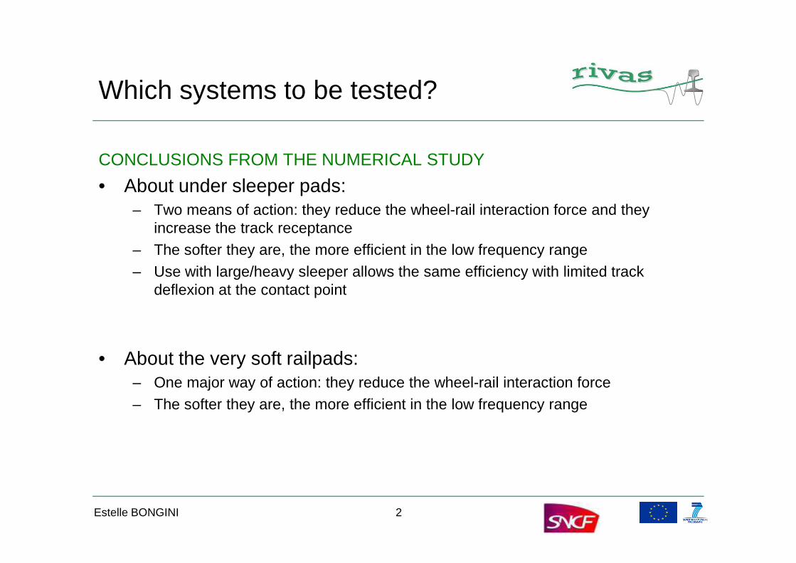
CONCLUSIONS FROM THE NUMERICAL STUDY
• About under sleeper pads:– Two means of action: they reduce the wheel-rail interaction force and they
increase the track receptance– The softer they are, the more efficient in the low frequency range– Use with large/heavy sleeper allows the same efficiency with limited track
deflexion at the contact pointdeflexion at the contact point
• About the very soft railpads:– One major way of action: they reduce the wheel-rail interaction force– The softer they are, the more efficient in the low frequency range
Estelle BONGINI 2
Which systems to be tested?
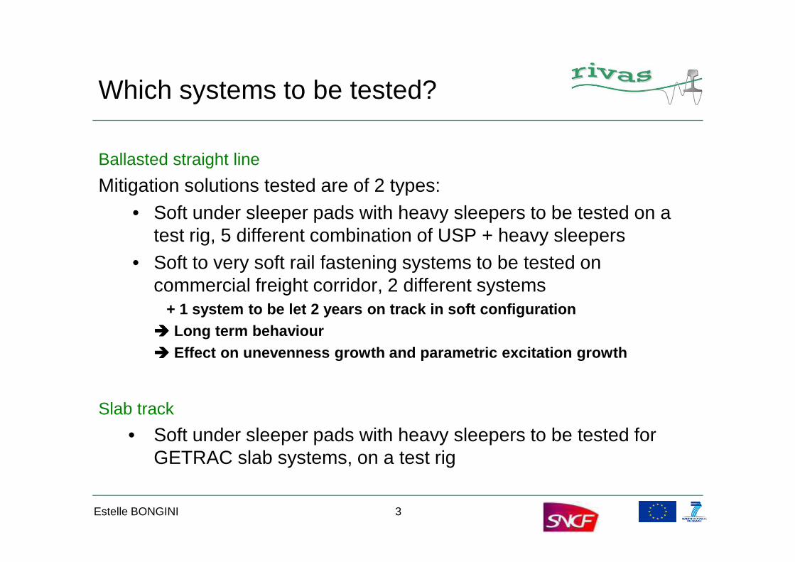
Ballasted straight line
Mitigation solutions tested are of 2 types:• Soft under sleeper pads with heavy sleepers to be tested on a
test rig, 5 different combination of USP + heavy sleepers• Soft to very soft rail fastening systems to be tested on
commercial freight corridor, 2 different systems commercial freight corridor, 2 different systems + 1 system to be let 2 years on track in soft configuration
���� Long term behaviour���� Effect on unevenness growth and parametric excitation growth
Slab track
• Soft under sleeper pads with heavy sleepers to be tested for GETRAC slab systems, on a test rig
Estelle BONGINI 3

Components designs / USP
• Different under sleeper pads presenting various static / dynamic stiffness• Combined with heavy sleepers specifically designed by RailOne for RIVAS
� Design and production phase of these specific components presented by Wojciech Nawrat
Estelle BONGINI 4

Components design / URP
• 2 different systems to be tested, proposed by Pandrol:– DFC: rail pads + under baseplate pads– VANGUARD system
• These 2 systems have to be tested on the same trial zone: they require to be installed on the same sleepers
� Dedicated sleepers specifically designed by SATEBA, to support both system� Dedicated DFC system, adapted to these sleepers
Estelle BONGINI 5
Lab testsrelated to track mitigation solutions implementation
Estelle BONGINI 6

Component characterization / USP
CHARACTERIZATION of COMPONENTSBAM has tested in lab various sets of {sleepers+USP} and the heavy sleepers
specimen, concrete block with USP
Tests performed on the USP:Static and dynamic Bedding modulus
The static bedding modulus is used for the calculation of the static compression of the rail under the service load
Estelle BONGINI 7
Test rig for small components (KPM), static and low frequency bedding modulus
compression of the rail under the service load
The low frequency bedding modulus Cdyn1 (f) is used for the calculation of the bending deformation of the rail under a rolling wheel. It determines the superstructure dynamics
The high frequency bedding modulus Cdyn2 (f) is determined for under-sleeper pads which shall reduce structure-borne noise. It characterises the mitigation potential of the under-sleeper pad
Tests protocols and results detailed in RIVAS Del 3.7

Component characterization / USP
Fatigue testThe mechanical fatigue strength test shall characterize the long term functionality of the USP and the bonding layer
Bond strength by pull outBond strength by pull outThe bond strength by pull-off shall be determined to ensure the required degree of the bonding between under sleeper pad and concrete
Shear test
Frost-thaw test
Estelle BONGINI 8
Tests protocols and results detailed in RIVAS Del 3.7

Component characterization / USP
Test performed on the heavy sleepers:Static test rail seat
Static test centre
Dynamic test rail seat
force
max. 120 kN/min 5 kN
Fcon
FcrnFcBn
Dynamic test rail seat
Fatigue test 2 Mio LC
Estelle BONGINI 9
time
10s < t < 5min
Static test, centre
Tests protocols and results detailed in RIVAS Del 3.7

Components characterization / URP
COMPLEMENTARY LAB TESTS
Characterization of the dynamic stiffness of the different fastening systems on a test bench with realistic loading (static pre-load + dynamic load) – 1 sleeper equipped with DFC and VANGUARD on a ballast bed.
Numerical simulations to assess the mitigation effect on the test site of these systems: an IL up to 20dB can be reached with VANGUARD installation
Estelle BONGINI 10
systems: an IL up to 20dB can be reached with VANGUARD installation
Test benchDynamic stiffness estimationUnder realistic load
Insertion loss of the free field velocity at 32m for the DFC system (dashed line) and the VANGUARD system (dotted line) when compared to the standard SNCF pads
Tests protocols and results detailed in RIVAS Del 3.4

Components certification / URP
Rail fastening systems to be used on commercial track and to be let for 2 years require a certificate of use, according to EN 13146 and EN 13481.
� Static and dynamic loading testsStatic and dynamic stiffness of the fastening systemPerformed before and after fatigue tests
� Inclined load testsResistance against canting of the rail, with an inclined load at 33°
Estelle BONGINI 11
Tests protocols and results to be detailed in RIVAS Del 3.5

Components certification / URP
� Electric insulation tests
� Longitudinal resistance before and after cyclic loading tests
� Extreme weather conditions tests
� Cyclic loading / Fatigue tests
DFC are certified for combination of pads corresponding to a global stiffness of 24kN/mm, for a commercial use period of 2 years.
Estelle BONGINI 12
Tests protocols and results to be detailed in RIVAS Del 3.5

Tests at scale 1related to track mitigation solutions implementation
Estelle BONGINI 13

USP implementationInsertion loss under cyclic loading
CEDEX TRACK BOX TESTS
CEDEX track box measurements have been carried out to assess the performances over time of a set of USP + heavy sleeper
tests performed:• After tamping and stabilization of the track, several quasi static passenger and freight train pass-by have been simulated
Estelle BONGINI 14
and freight train pass-by have been simulated• 12195 quasi static pass-by of freight train simulated, corresponding to 2Mo axle loads• Track receptances are measured• Track quasi static behaviour is checked regularly during the tests: during the load cycles, static tests have been performed to check the track behaviour
Tests protocols and results detailed in RIVAS Del 3.7

USP implementationInsertion loss under cyclic loading
CEDEX TRACK BOX TESTS
Estelle BONGINI 15
USP implementationInsertion loss under cyclic loading
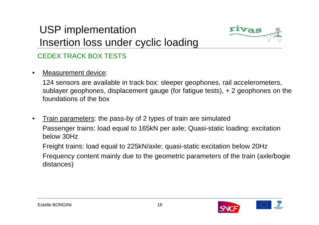
• Measurement device:124 sensors are available in track box: sleeper geophones, rail accelerometers, sublayer geophones, displacement gauge (for fatigue tests), + 2 geophones on the foundations of the box
CEDEX TRACK BOX TESTS
• Train parameters: the pass-by of 2 types of train are simulatedPassenger trains: load equal to 165kN per axle; Quasi-static loading: excitation below 30HzFreight trains: load equal to 225kN/axle; quasi-static excitation below 20HzFrequency content mainly due to the geometric parameters of the train (axle/bogie distances)
Estelle BONGINI 16

USP implementationInsertion loss under cyclic loading
CEDEX TRACK BOX TESTS
Simulation of train passage over a medium class track (i.e. with longitudinal track defects)
Simulation of vertical irregularities according to the transfer function established between the geometric irregularities and the corresponding dynamic load (with a given track stiffness and damping), in the frequency domain.
Dynamic load time history
Estelle BONGINI 17
1,E-13
1,E-12
1,E-11
1,E-10
1,E-09
1,E-08
1,E-07
1,E-06
1,E-05
1,E-04
0,1 1 10 100
Sing
le-s
ided
PSD
tra
ck ir
regu
lari
ty (m
2 /(ra
d/m
))
Wavenunber (rad/m)
ORE B176 low ORE B176 high psd_0_150
Adopted PSD versus ORE PSD’s functions
1 s dynamic load time history sample derived from the adopted PSD

USP implementationInsertion loss under cyclic loading
Insertion loss at the middle of the embankment for TS3 system when compared to TS2 system
CEDEX TRACK BOX TESTS RESULTS
4
6
8IL PTQ Geo137 GPvsGS
0
2
4
6IL FTQ GeoE137 GPvsGs
10
15
20IL DFT GeoE137 GPvsGS
Estelle BONGINI 18
100 101 102-4
-2
0
2
f(Hz)
IL(d
B)
100 101 102-10
-8
-6
-4
-2
0
f(Hz)
IL(d
B)
100
101
102-15
-10
-5
0
5
f(Hz)
IL(d
B)
Passenger train quasi-static velocity insertion loss
Freight vehicle quasi-static velocity insertion loss
Freight vehicle dynamic velocity insertion loss

USP implementationInsertion loss under cyclic loading
Track receptances obtained with a 112.5 kN static load applied to the railCEDEX TRACK BOX TESTS RESULTS
10-7
10-6
10-5Com GSGP 225kN_C_SHH AC0E
10-10
10-9
10-8
10-7Com GSGP st225kN_B_10kN_Act32Hz AC0E
Estelle BONGINI 19
With a 10 kN dynamic peak load pulse (15.6 ms rising time) generated with one servo-hydraulic cylinder.
101 102 10310
-12
10-11
10-10
10-9
10-8
f(Hz)
Rec
epta
nce
(m/N
)
TS3 SystemTS2 System
101 102 10310-15
10-14
10-13
10-12
10-11
10-10
f(Hz)
Rec
epta
nce
(m/N
)
TS3 SystemTS2 System
With a 8 kN dynamic peak load pulse (0.5 ms rising time) generated with light hammer (0.45 Kg).

USP implementation / test rig installation
The heavy sleepers equipped with different type of USP have been tested few days ago, on a test rig with dedicated measurement device (a specific loading system) presented in the next presentations
� presented by Rüdiger Garburg and Michael Mistler
Estelle BONGINI 20
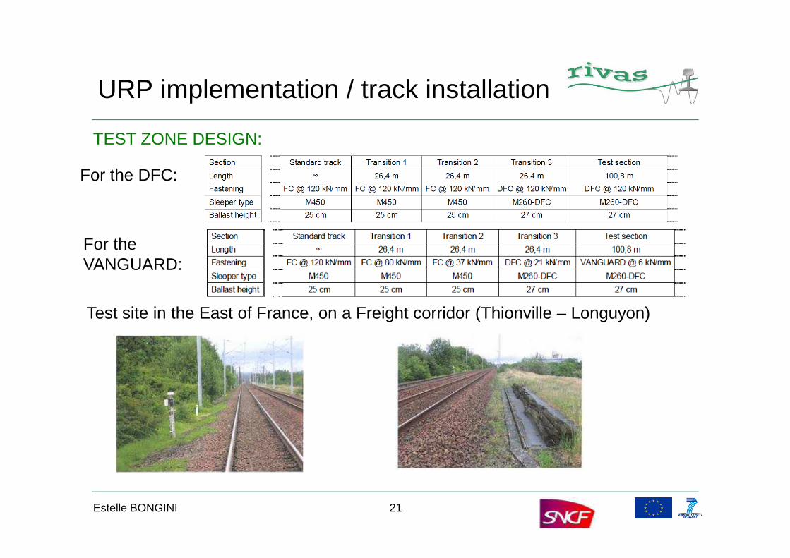
URP implementation / track installation
TEST ZONE DESIGN:
For the DFC:
For the VANGUARD:
Estelle BONGINI 21
Test site in the East of France, on a Freight corridor (Thionville – Longuyon)

URP implementation / track installation
TEST ZONE DESIGN: TRANSITION ZONES
• Estimation of the track stiffness evolution
0 20 40 60 80 100 12020
40
60
80
100
120
140
Track
stiffnes
s (kN/m
m)
Estelle BONGINI 22
• Estimation of the rail-wheel interaction force at these transitions, to be compared with the interaction force experienced along a track with non-critical vertical defects
0 20 40 60 80 100 12020
Abscissa on the track (m)
0 500 1000 1500-18
-12
-6
0
6
12
18
24
Interaction force (k
N)
Interaction force for a leading wheel - Passenger coach
Abscissa on the track (m)0 500 1000 1500
20
60
100
140
180
220
260
300
Track stiffnes
s (kN/m
m)
Wheel-Rail interaction force on:- perfect track with transition zones for the track stiffness (left)- same track with usual geometrical defects (right)� No emergence on the interaction force due to the transition zones350 400 450 500 550 600 650 700 750
-3.6
-2.4
-1.2
0
1.2
2.4
3.6
4.8
Intera
ction force (kN)
Interaction force for a leading wheel - FRET wagon
abscissa on the track (m)350 400 450 500 550 600 650 700 750
20
60
100
140
180
220
260
300
Track
stiffnes
s (kN/m
m)

URP implementation / track installation
• Dedicated sleepers will be installed during a track removal with DFC fastening system equipped with « reference » pads (equivalent global stiffness of the fastening system eq. to 90kN/mm)
• Pads (under rail or under baseplate) will be changed to gradually
TEST ZONE CONSTRUCTION
• Pads (under rail or under baseplate) will be changed to gradually decrease the stiffness of the global system down to 24kN/mm
• This version at 24kN/mm will be let in the track over 2 years
• VANGUARD system could be use on the same sleepers for few days installation, allowing a 6kN/mm stiffness of the fastening system to be tested
Estelle BONGINI 23
URP implementation / track installation
TESTS TO BE PERFORMED: for each DFC / VANGUARD configuration
• Commercial Freight and regional trains traffic
• Measurements on a reference site and the test site: – ground dynamic properties via SASW characterization– ground dynamic properties via SASW characterization– Track receptances– rail accelerations during pass-by – ground vibrations during pass-by @ 8m, 16m and perhaps 32m– Track deflexion to check track stability
Estelle BONGINI 24

This afternoon…
• Presentations of: – The measurement protocol for assessing the mitigation measure
efficiency– the specific loading system for the test rig – the design process for the heavy sleeper equipped with USP– The optimization of track maintenance– The optimization of track maintenance– The definition of a reference track for GV issue
Estelle BONGINI 25

Thank you for your attention.
Visit our website wwww.rivas-project.eu
Estelle BONGINI 26


