From Solar Sails to Laser Sails - ntrs.nasa.gov · • NASA currently has no firm interplanetary or...
36
From Solar Sails to Laser Sails Les Johnson, NASA Marshall Space Flight Center Edward E. Montgomery, Nexolve/Jacobs ESSSA Group December 15, 2017 New York City College of Technology, Brooklyn, NY https://ntrs.nasa.gov/search.jsp?R=20170012350 2018-08-18T01:50:07+00:00Z
Transcript of From Solar Sails to Laser Sails - ntrs.nasa.gov · • NASA currently has no firm interplanetary or...
From Solar Sails to Laser Sails
Les Johnson, NASA Marshall Space Flight Center Edward E. Montgomery, Nexolve/Jacobs ESSSA Group
December 15, 2017New York City College of Technology, Brooklyn, NY
https://ntrs.nasa.gov/search.jsp?R=20170012350 2018-08-18T01:50:07+00:00Z
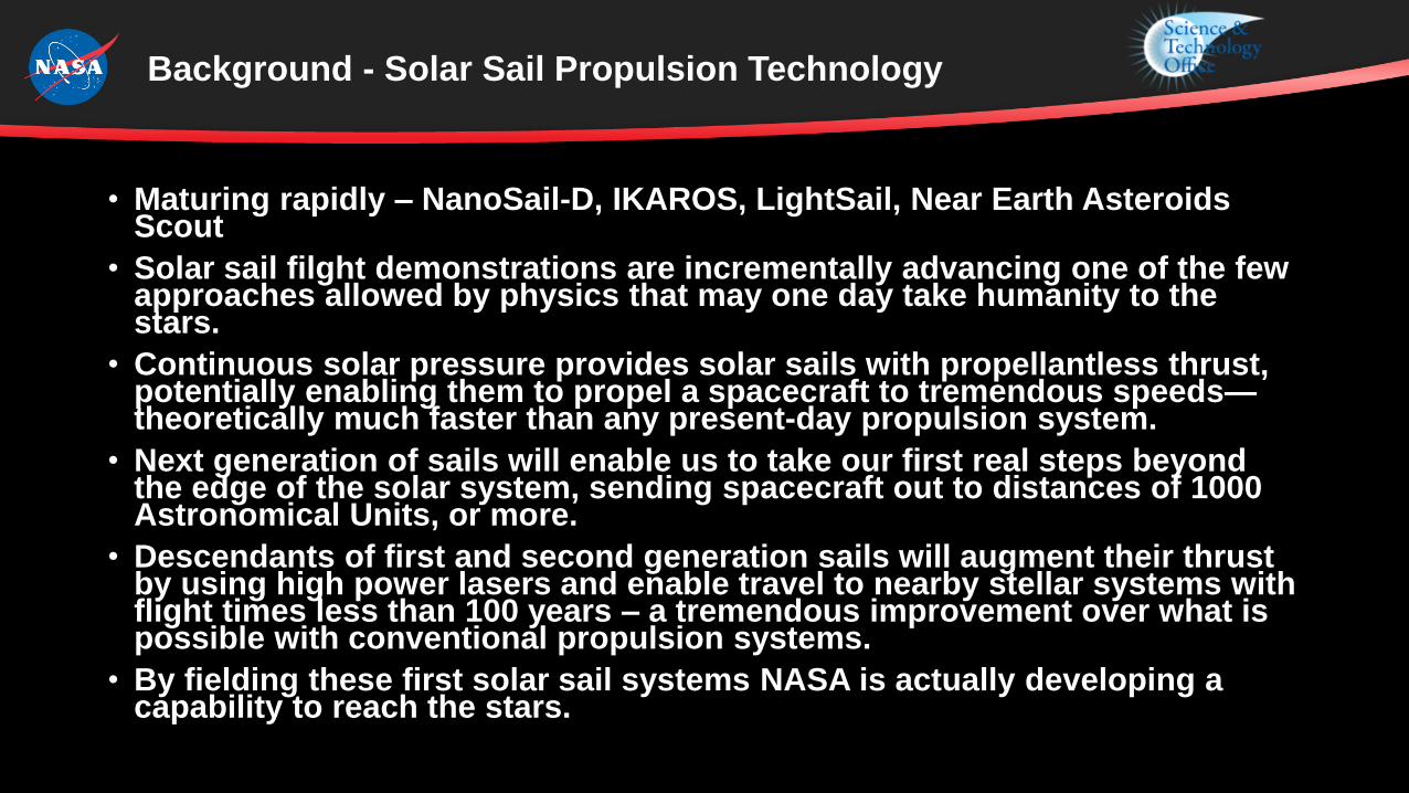
• Maturing rapidly – NanoSail-D, IKAROS, LightSail, Near Earth Asteroids Scout
• Solar sail filght demonstrations are incrementally advancing one of the few approaches allowed by physics that may one day take humanity to the stars.
• Continuous solar pressure provides solar sails with propellantless thrust, potentially enabling them to propel a spacecraft to tremendous speeds—theoretically much faster than any present-day propulsion system.
• Next generation of sails will enable us to take our first real steps beyond the edge of the solar system, sending spacecraft out to distances of 1000 Astronomical Units, or more.
• Descendants of first and second generation sails will augment their thrust by using high power lasers and enable travel to nearby stellar systems with flight times less than 100 years – a tremendous improvement over what is possible with conventional propulsion systems.
• By fielding these first solar sail systems NASA is actually developing a capability to reach the stars.
Background - Solar Sail Propulsion Technology
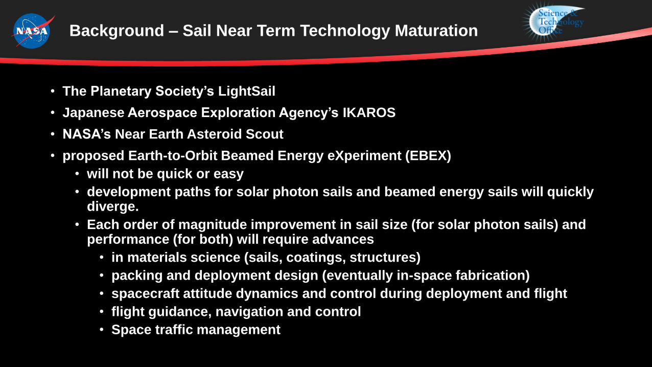
• The Planetary Society’s LightSail
• Japanese Aerospace Exploration Agency’s IKAROS
• NASA’s Near Earth Asteroid Scout
• proposed Earth-to-Orbit Beamed Energy eXperiment (EBEX)
• will not be quick or easy
• development paths for solar photon sails and beamed energy sails will quickly diverge.
• Each order of magnitude improvement in sail size (for solar photon sails) and performance (for both) will require advances
• in materials science (sails, coatings, structures)
• packing and deployment design (eventually in-space fabrication)
• spacecraft attitude dynamics and control during deployment and flight
• flight guidance, navigation and control
• Space traffic management
Background – Sail Near Term Technology Maturation

• A notional solar and beamed energy sail technology maturation plan (with performance metrics) will be outlined.
• A discussion of the real-world engineering challenges facing today’s first generation missions and the design and development challenges for those in the next generation will be described.
• Finally, a step-by-step approach for developing sails of increasing capability and performance will be proposed – leading to the sailcraft required for true interstellar travel.
• Focus of this effort: 3 Paths
• Solar Sail
• Laser Sail
• Break Through Starshot
Contents

Solar Sails
Roadmap Development Guidelines
• Dates for Missions to Destinations depend on • Science and Exploration Priorities• Current state of the art• Required technology advancement• required technology and infrastructure advancement
• NASA currently has no firm interplanetary or interstellar mission objectives beyond Mars exploration – Missions presented here are authors choice
• Destinations will progress in time by distance• Earth-to Orbit• Earth Orbit to Solar System• Earth Orbit to Interstellar• Solar system to Interstellar• Interstellar to Solar System

Roadmap Development Guidelines
Build/Launch Infrastructure
• Operations will remain Earth-based until launch cost is significantly reduced (to the point they no longer outweigh• Fabrication limitations of 1 g• Attenuation by atmosphere• Rotation of the Earth effect on Duty Cycle
• Lasers are only useful within local planetary space (diffraction limit and realistic apertures)• Availability of High Power Photon Stream
• Sun: 1014 TW• Earth-Based
• 18 TW Earth total usage, 105 TW incident solar, • Hydro - Largest plants (hydro): Three Gorges @ 22.5 GW, US Grand Coulee at 6.8 GW• Nuclear - Largest Plant Kashiwaleaki-Kariwa* @8.2 GW (7 reactors), US Palo Verde @ 4.4 GW
• Space Based • ISS PV @ 120 kW• Nuclear (NASA Technology Roadmap)
• Fission – 10-100 kW, <10 MW Mars Surface Operations, 2033• Fission >10 MW Nuclear Electric Propulsion, 2033• Fusion ~10 GW >2033
• Key Infrastructure Masses• Sail Manufacturing• Laser+Power+Thermal+Beam Control• Spacecraft+Payload
Currently inoperable due to Earthquake damage.

The Sails We Need*
• Size: >>1 km2
• Areal density: <1 gram/m2
• Must be affordable and launchable (or able to fabricated in space)
* preliminary

The sails we haveare not close to what we need
• Size: ~100 m2 to ~200 m2
• Areal density: 25 - 300 g/m2
NanoSail-D as seen from the groundIKAROS in deep space
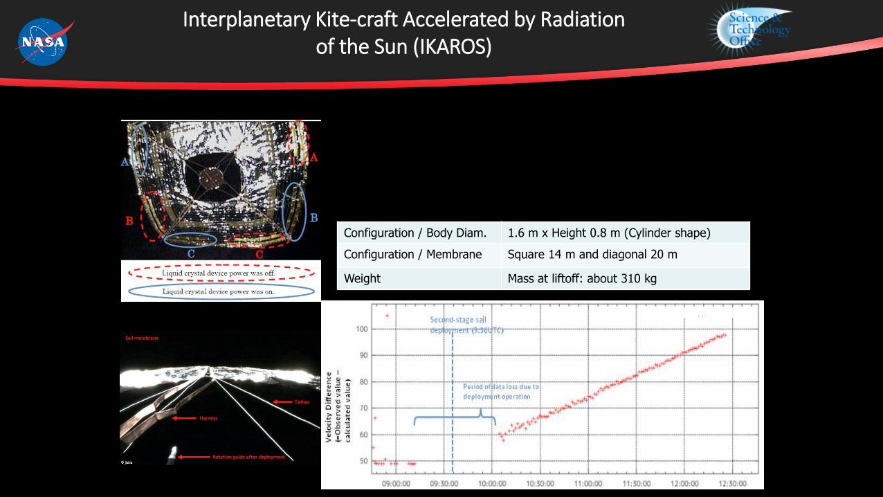
Interplanetary Kite-craft Accelerated by Radiation of the Sun (IKAROS)
• IKAROS was launched on May 21, 2010• IKAROS has demonstrated deployment of a solar sailcraft,
acceleration by photon pressure, and attitude control.•Deployment was by centrifugal force
.
Configuration / Body Diam. 1.6 m x Height 0.8 m (Cylinder shape)
Configuration / Membrane Square 14 m and diagonal 20 m
Weight Mass at liftoff: about 310 kg

• 3U Cubesat design
• Sail Material: aluminized 4.5 micron Mylar film
• 32 square meters solar sail area fully deployed
• LightSail-A (flew 2015) and LightSail-B (2016)
LightSail-A and -B

Near Earth Asteroid Scout
The Near Earth Asteroid Scout Will• Image/characterize a NEA during a slow
flyby • Demonstrate a low cost asteroid
reconnaissance capability
Key Spacecraft & Mission Parameters
• 6U cubesat (20 cm X 10 cm X 30 cm)
• ~86 m2 solar sail propulsion system
• Manifested for launch on the Space Launch
System (EM-1/2019)
• Up to 2.5 year mission duration
• 1 AU maximum distance from Earth
Solar Sail Propulsion System Characteristics
• ~ 7.3 m Trac booms
• 2.5m aluminized CP-1 substrate
• > 90% reflectivity
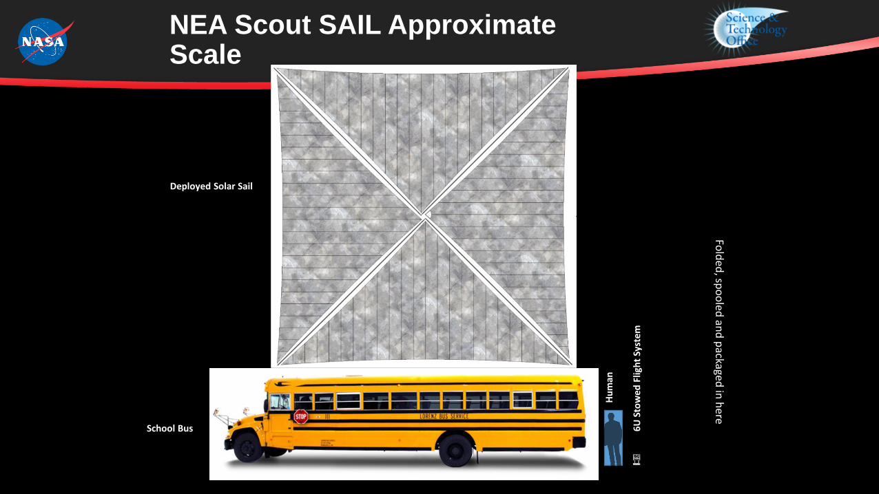
NEA Scout SAIL Approximate Scale
6U
Sto
wed
Flig
ht
Syst
em
Deployed Solar Sail
13
Hu
man
School Bus
Deployed Solar Sail
Fold
ed, sp
oo
led an
d p
ackaged in
he
re

No Sail Missions Yet Approved Beyond 2018
2015 2020 2025 2030
THE NEED Size: >>106 m2
Areal density: ~< 1 gram/m2
32 m2
NEA ScoutATP 20142018 – 2021
LightSail A/B2015 / 2017
85 m2
30 g/m2 (sail system)

Solar and Beam Energy Maturation Plan
NASA Solar Sail Roadmap (circa 2005)
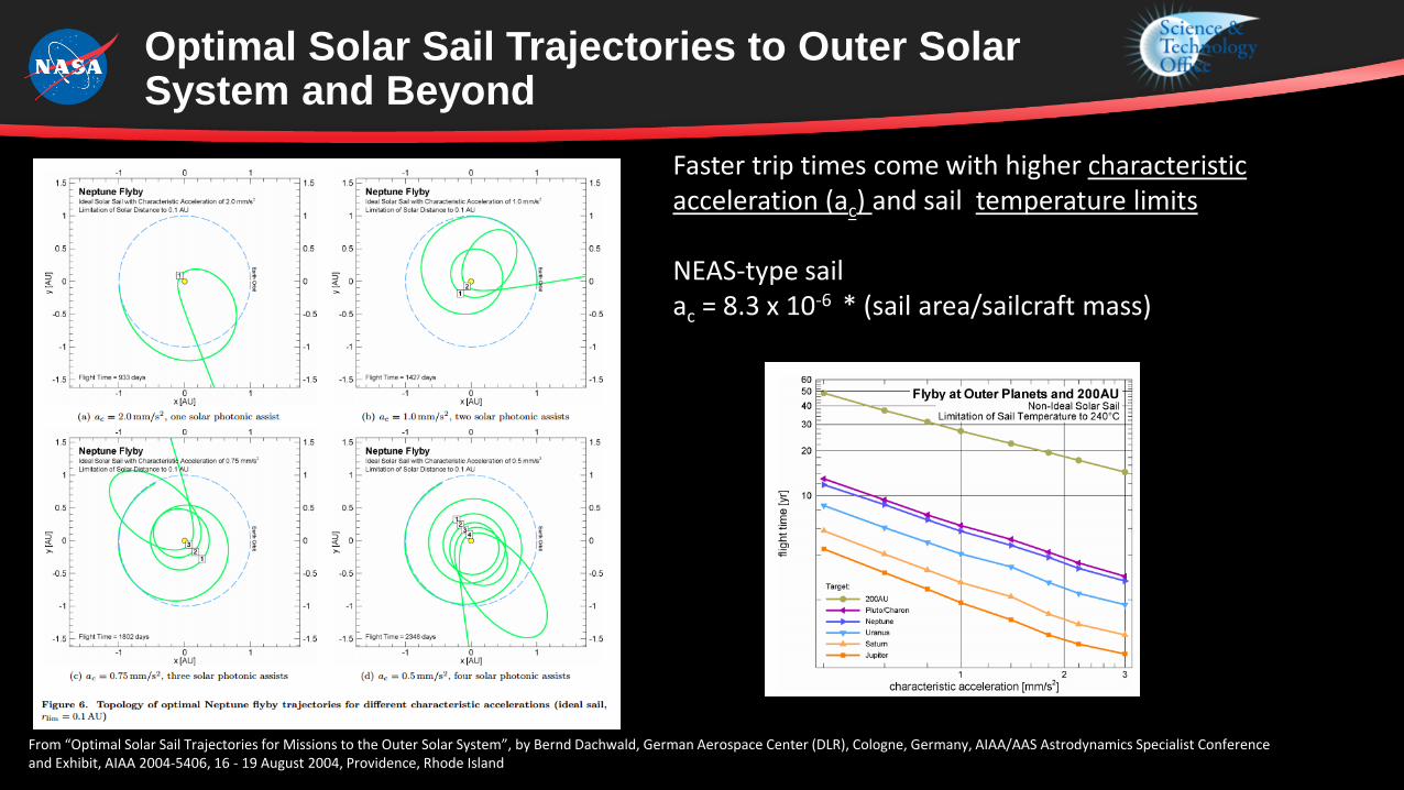
Optimal Solar Sail Trajectories to Outer Solar System and Beyond
From “Optimal Solar Sail Trajectories for Missions to the Outer Solar System”, by Bernd Dachwald, German Aerospace Center (DLR), Cologne, Germany, AIAA/AAS Astrodynamics Specialist Conference and Exhibit, AIAA 2004-5406, 16 - 19 August 2004, Providence, Rhode Island
Faster trip times come with higher characteristic acceleration (ac) and sail temperature limits
NEAS-type sail ac = 8.3 x 10⁻⁶ * (sail area/sailcraft mass)

Laser Sails

Optimal Laser Sail Trajectories to Outer Solar System and Beyond
• To Be Determined – Much study needed
• Laser photons in addition to solar photons will increase characteristic acceleration for the same sail area and sailcraft mass – as long as sail can withstand additional thrust loads and heating
• Laser in low Solar orbit (beaming tangential to sun)• Optimal place to add energy to an orbit is at its closest approach to central body (sun). • At perihelion, the sail attitude should be edge on to the sun to reduce thermal load (while still
benefiting from gravity assist)• Before and After perihelion, the sail should orient to more normal with the sun to capture high flux
for thrust .• Located near sun, laser would enjoy ample power harnessed from solar energy
• Laser in Solar Orbit • Action distance of laser is small on interplanetary scale, even for very large sails and beam directors• Cycler orbits may be possible to allow multiple conjunctions between laser and sail craft• Nuclear Fusion Power likely necessary for lasers based or orbiting in outer solar system to be
effective

Background – Laser Near Term Technology Maturation
• FEL – scalable due to vacuum media, large footprint, highest power achieved ~11 watts, minimal current research
• Chemical
• CO2, COIL – USAF Airborne Laser , Boeing 747, MW class, scrapped 2014
• Deuterium Fluoride – MIRACL, MW class, last operational 1997
• Solid State
• Diode pumped
• Solid State – JHPPSL – US Army – 100kW in lab, GBAD
• Fiber – US Army RELI in HELMTT, 10 kW, 60 kw in 2018
• Tiled Arrays – LaWS in USS Ponce – 30 kW, 150 kW in 2018
• Phased Arrays – DARPA lab – Excalibur – 21 kW, currently ?
• Spectrally Combined
• Coherently Combined
• Rare Gas and alkali lasers, TRL 1-3 lab experiments
• Direct Diode – commercially available up 8 kW, beam quality a challenge
• Atom (BEC) Laser – TRL 2

On-Orbit Beam DirectorsAperture and Mass
0.5 m 2.4 8.0 201500 kg 2920 6500 36,000
High Energy Laser Mobile
Demonstrator
Hubble Space Telescope
James Webb Space Telescope
Advanced Large Aperture Space
Telescope Concept

Update to 2010 BEP Symposium Presentation: Exponential Growth of Continuous Working Solid State Lasers
2010 Prediction Source: “Solid-State Laser Weapon Systems, Bridging the Gap — or Bridge Too Far?”, by Andrew Krepinevich, Tom Ehrhard, and Barry Watts, Center for Strategic & Budgetary Assessments (CSBA), May 20, 2009.
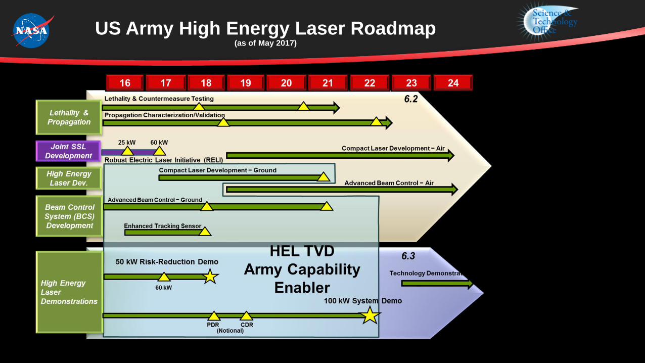
US Army High Energy Laser Roadmap (as of May 2017)

The diameter of the sailcraft d, is set equal to the diameter of the first Airy ring at a range R from a circular beam director aperture D. Assuming a 1 micron wavelength LEO-based laser, perfect beam and optics, no atmosphere, and no jitter, that relationship follows from the Fraunhoffer Diffraction equation1 to be
d = 2.44 R l /D Independent of laser power level
The total power (P) within the first Airy ring projected onto a surface from a laser with power Po is:
P = 0.838 Po Independent of propagation distance
Beaming Interplanetary distances
2.4 8 20 meter Beam Director
1 M. Born and E. Wolf, Principles of Optics (Pergamon Press, New York, 1965)
See next chart

Even Largest Beam Director Considered Does Not Fill Sails Beyond the Earth’s Gravitational Sphere of Influence (Hill Radius)
Sail Area10 m2
1200 m240000 m2
1 micron wavelength, diffraction-limitedlaser in LEO @ 200 km

Earth to Mars Trip Time Shortened by Increasing Characteristic Acceleration of the Sailcraft
[ after Robert H. Frisbee and John R. Brophy, Jet Propulsion Laboratory, “Inflatable Solar Sails for Low-Cost Robotic Mars Missions”, AlAA 97-2762, 33rd AIAA/ASME/SAE/ASEE Joint Propulsion Conference & Exhibit, July 6-9, 1997, Seattle, WA]
[after, Wright, Jerome L. (1992), Space Sailing, Gordon and Breach Science Publishers]

EBEX, Earth-to-Orbit Beamed Energy ExperimentMission Concept Study
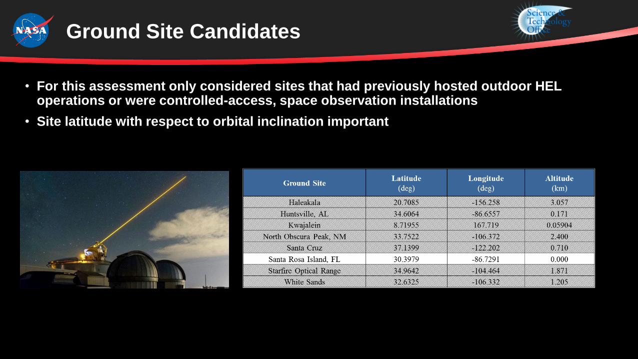
• For this assessment only considered sites that had previously hosted outdoor HEL operations or were controlled-access, space observation installations
• Site latitude with respect to orbital inclination important
Ground Site Candidates

EBEX Performance Analysis Method
• Method based on:
• “Beam Control for Laser Systems”, by Dr. Paul Merritt, published by the Directed Energy Professional Society, Albuquerque, N.M., 2012, Library of Congress Control Number: 2010929641]
• “Linear Photonic Thrust Model and its Application to the L’Garde Solar Sail Surface”, by Gyula Greschik, 54th AIAA/ASME/ASCE/AHS/ASC Structures, Structural Dynamics, and Materials Conference, April 8-11, 2013, Boston, Massachusetts

Power Delivered to Orbit
Ligh
tSai
l 2 r
adiu
s
Diffraction and jitter combine to “spill” ~50% of energy past LightSail 2 at 700 km orbit altitude
Power in spot, P = Iave * Area
where Area = p rA2
sj = jitter
sD = diffraction
Ipj = Ipeak *sj
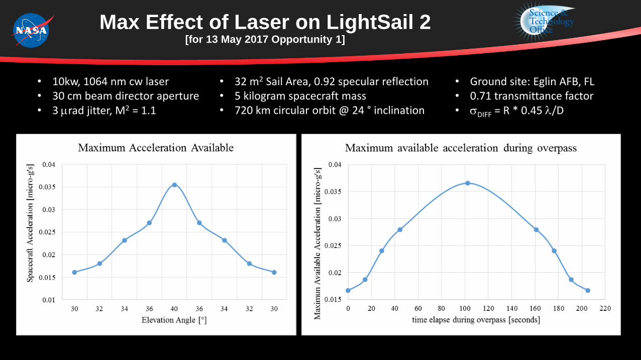
Max Effect of Laser on LightSail 2[for 13 May 2017 Opportunity 1]
• 10kw, 1064 nm cw laser• 30 cm beam director aperture• 3 mrad jitter, M2 = 1.1
• 32 m2 Sail Area, 0.92 specular reflection• 5 kilogram spacecraft mass• 720 km circular orbit @ 24 ° inclination
• Ground site: Eglin AFB, FL• 0.71 transmittance factor• sDIFF = R * 0.45 l/D

Max DV of Laser on LightSail 2[for 13 May 2017 Opportunity 1]
• 10kw, 1064 nm cw laser• 30 cm beam director aperture• 3 mrad jitter, M2 = 1.1
• 32 m2 Sail Area, 0.92 specular reflection• 5 kilogram spacecraft mass• 720 km circular orbit @ 24 ° inclination
• Ground site: Eglin AFB, FL• 0.71 transmittance factor• sDIFF = R * 0.45 l/D
Single overpass max cumulativeDV = 0.056 m/sec
0.1 m/sec DV goal may be exceeded with two or more accesses
An optimum spacecraft attitude program required to achieve max results

Break Through Starshot
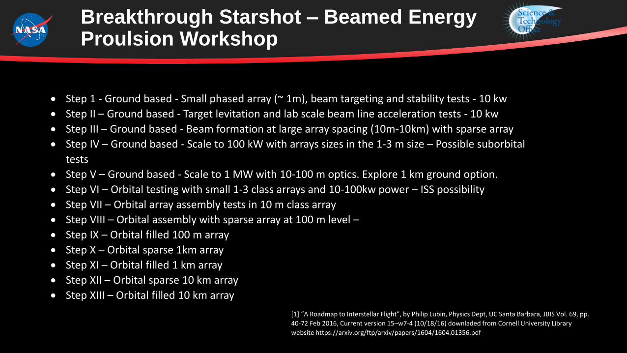
Breakthrough Starshot – Beamed Energy Proulsion Workshop
Step 1 - Ground based - Small phased array (~ 1m), beam targeting and stability tests - 10 kw
Step II – Ground based - Target levitation and lab scale beam line acceleration tests - 10 kw
Step III – Ground based - Beam formation at large array spacing (10m-10km) with sparse array
Step IV – Ground based - Scale to 100 kW with arrays sizes in the 1-3 m size – Possible suborbital
tests
Step V – Ground based - Scale to 1 MW with 10-100 m optics. Explore 1 km ground option.
Step VI – Orbital testing with small 1-3 class arrays and 10-100kw power – ISS possibility
Step VII – Orbital array assembly tests in 10 m class array
Step VIII – Orbital assembly with sparse array at 100 m level –
Step IX – Orbital filled 100 m array
Step X – Orbital sparse 1km array
Step XI – Orbital filled 1 km array
Step XII – Orbital sparse 10 km array
Step XIII – Orbital filled 10 km array
[1] “A Roadmap to Interstellar Flight”, by Philip Lubin, Physics Dept, UC Santa Barbara, JBIS Vol. 69, pp.
40-72 Feb 2016, Current version 15–w7-4 (10/18/16) downladed from Cornell University Library
website https://arxiv.org/ftp/arxiv/papers/1604/1604.01356.pdf

Comparison of Key Perfromance Parametrics
Roadmap Development Guidelines
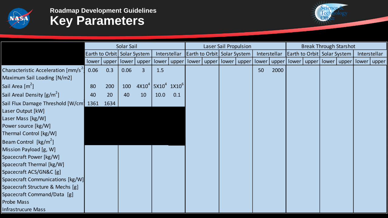
Key Parameters
Solar Sail Laser Sail Propulsion Break Through Starshot
lower upper lower upper lower upper lower upper lower upper lower upper lower upper lower upper lower upper
Characteristic Acceleration [mm/s2] 0.06 0.3 0.06 3 1.5 50 2000
Maximum Sail Loading [N/m2]
Sail Area [m2] 80 200 100 4X10⁴ 5X10⁴ 1X10⁶
Sail Areal Density [g/m2] 40 20 40 10 10.0 0.1
Sail Flux Damage Threshold [W/cm2]1361 1634
Laser Output [kW]
Laser Mass [kg/W]
Power source [kg/W]
Thermal Control [kg/W]
Beam Control [kg/m2]
Mission Payload [g, W]
Spacecraft Power [kg/W]
Spacecraft Thermal [kg/W]
Spacecraft ACS/GN&C [g]
Spacecraft Communications [kg/W]
Spacecraft Structure & Mechs [g]
Spacecraft Command/Data [g]
Probe Mass
Infrastrucure Mass
Earth to Orbit Solar System InterstellarEarth to Orbit Solar System Interstellar Earth to Orbit Solar System Interstellar

Conclusions
• An evolutionary multi-path roadmap has been derived for the development of photon sail propulsion for near-term Earth Orbit, Interplanetary, and then Interstellar science and exploration missions
• Some Commonality in Technology Advancement Needs exist• High Energy, Efficient, Lightweight Lasers• Lightweight, High Flux Tolerant Sails• Trajectory Optimization• Precision Guidance, Navigation, and Control• Reduced Launch Cost• Space Power/Energy Storage• Long Range, Low Power Communication Systems• Miniaturized, Robust, Low power Spacecraft Bus
• Significant levels of Technology Development must start now to enable even the most modest missions in the next half century